EP3508758B1 - Generator driven gear for integrated drive generator - Google Patents
Generator driven gear for integrated drive generator Download PDFInfo
- Publication number
- EP3508758B1 EP3508758B1 EP19150187.3A EP19150187A EP3508758B1 EP 3508758 B1 EP3508758 B1 EP 3508758B1 EP 19150187 A EP19150187 A EP 19150187A EP 3508758 B1 EP3508758 B1 EP 3508758B1
- Authority
- EP
- European Patent Office
- Prior art keywords
- roll angle
- gear teeth
- degrees
- outer gear
- gear
- Prior art date
- Legal status (The legal status is an assumption and is not a legal conclusion. Google has not performed a legal analysis and makes no representation as to the accuracy of the status listed.)
- Active
Links
Images

Classifications
-
- F—MECHANICAL ENGINEERING; LIGHTING; HEATING; WEAPONS; BLASTING
- F16—ENGINEERING ELEMENTS AND UNITS; GENERAL MEASURES FOR PRODUCING AND MAINTAINING EFFECTIVE FUNCTIONING OF MACHINES OR INSTALLATIONS; THERMAL INSULATION IN GENERAL
- F16H—GEARING
- F16H55/00—Elements with teeth or friction surfaces for conveying motion; Worms, pulleys or sheaves for gearing mechanisms
- F16H55/02—Toothed members; Worms
- F16H55/08—Profiling
-
- F—MECHANICAL ENGINEERING; LIGHTING; HEATING; WEAPONS; BLASTING
- F02—COMBUSTION ENGINES; HOT-GAS OR COMBUSTION-PRODUCT ENGINE PLANTS
- F02C—GAS-TURBINE PLANTS; AIR INTAKES FOR JET-PROPULSION PLANTS; CONTROLLING FUEL SUPPLY IN AIR-BREATHING JET-PROPULSION PLANTS
- F02C7/00—Features, components parts, details or accessories, not provided for in, or of interest apart form groups F02C1/00 - F02C6/00; Air intakes for jet-propulsion plants
- F02C7/36—Power transmission arrangements between the different shafts of the gas turbine plant, or between the gas-turbine plant and the power user
-
- F—MECHANICAL ENGINEERING; LIGHTING; HEATING; WEAPONS; BLASTING
- F16—ENGINEERING ELEMENTS AND UNITS; GENERAL MEASURES FOR PRODUCING AND MAINTAINING EFFECTIVE FUNCTIONING OF MACHINES OR INSTALLATIONS; THERMAL INSULATION IN GENERAL
- F16H—GEARING
- F16H55/00—Elements with teeth or friction surfaces for conveying motion; Worms, pulleys or sheaves for gearing mechanisms
- F16H55/02—Toothed members; Worms
- F16H55/17—Toothed wheels
-
- F—MECHANICAL ENGINEERING; LIGHTING; HEATING; WEAPONS; BLASTING
- F02—COMBUSTION ENGINES; HOT-GAS OR COMBUSTION-PRODUCT ENGINE PLANTS
- F02C—GAS-TURBINE PLANTS; AIR INTAKES FOR JET-PROPULSION PLANTS; CONTROLLING FUEL SUPPLY IN AIR-BREATHING JET-PROPULSION PLANTS
- F02C7/00—Features, components parts, details or accessories, not provided for in, or of interest apart form groups F02C1/00 - F02C6/00; Air intakes for jet-propulsion plants
- F02C7/32—Arrangement, mounting, or driving, of auxiliaries
-
- F—MECHANICAL ENGINEERING; LIGHTING; HEATING; WEAPONS; BLASTING
- F05—INDEXING SCHEMES RELATING TO ENGINES OR PUMPS IN VARIOUS SUBCLASSES OF CLASSES F01-F04
- F05D—INDEXING SCHEME FOR ASPECTS RELATING TO NON-POSITIVE-DISPLACEMENT MACHINES OR ENGINES, GAS-TURBINES OR JET-PROPULSION PLANTS
- F05D2260/00—Function
- F05D2260/40—Transmission of power
- F05D2260/403—Transmission of power through the shape of the drive components
- F05D2260/4031—Transmission of power through the shape of the drive components as in toothed gearing
Definitions
- This application relates to an integrated drive generator and a method of replacing a generator driven gear for an integrated drive generator.
- Integrated drive generators are known and often utilized in aircraft.
- a gas turbine engine on the aircraft provides a drive input into a generator input shaft.
- the generator typically includes a disconnect shaft that can transmit the input into a gear differential.
- the gear differential selectively drives a main generator and its generator driven gear to provide electric power for various uses on the aircraft.
- the generated power be of a desired constant frequency.
- the speed from the input shaft will vary during operation of the gas turbine engine. This would result in variable frequency.
- Integrated drive generators are provided with speed trimming hydraulic units. Gears associated with the differential and, in particular, a ring gear portion, provide rotation from the differential back into the trimming unit. A carrier also rotates another portion of the trimming unit. The trimming unit is operable to result in the output speed of the differential being effectively constant, such that electric power of a desirable frequency is generated.
- the generator is mounted between two housing portions and a seal plate is mounted between the two housing portions.
- various accessory systems such as various pumps
- various accessory systems are driven by the output ring gear of the differential through an accessory drive gear.
- Two such pumps are scavenge and charge pumps.
- a drive gear drives these pumps.
- FIG. 1 shows an integrated drive generator 20. As shown, housing portions 18 and 19 surround the integrated drive generator and a seal plate 17 sits between the housing portions 18 and 19.
- a gas turbine engine 22 may drive an input shaft 23 which selectively drives a disconnect assembly 26.
- the disconnect assembly 26 in turn, drives a carrier shaft 28, which drives a carrier in a gear differential 30.
- Gears 38 have a gear interface 42 with a first ring gear portion 40.
- Gears 36 have a gear interface 48 with a second ring gear portion 46.
- Ring gear portion 40 has a gear interface 50 with a main generator 51 and its driven gear 152.
- driven gear 152 When driven gear 152 is driven to rotate, it rotates a rotor 56 associated with a stator 58 of the main generator as well as an exciter rotor 60. Electric power is generated for a use 62, as known.
- the frequency of the generated electric power be at a desired frequency.
- a gear 15 that is part of the carrier has a gear interface 16 with a gear 13 driving a shaft 14 also within the speed trimmer.
- the speed trimmer 66 includes a variable unit 72 and a fixed unit 76.
- the units 72 and 76 may each be provided with a plurality of pistons and a swash plate arrangement. If the input speed of the gear 13 is too high, the speed of the gear 152 will also be too high, and hence, the speed trimmer 66 acts to lower the speed of the trim gear 46 which will drop the speed of gear 152. On the other hand, if the input speed is too low, the speed trimmer will increase the trim gear speed and he speed seen by gear 152 will increase.
- variable unit 72 receives an input through gear 13 that is proportional to the speed of the input shaft 23.
- the variable unit 72 also receives a control input from a control monitoring the speed of the generator rotor 56.
- the position of the swash plate in the variable unit 72 is changed to in turn change the speed and direction of the fixed unit 76.
- the fixed unit 76 can change the speed, and direction of rotation of the shaft 70, and this then provides control back through the trim ring gear 46 to change the speed reaching the generator.
- the speed trimmer 66 results in the frequency generated by the generator being closer to constant, and at the desired frequency.
- a permanent magnet generator 32 rotates with the ring gear 40.
- An accessory drive shaft 29 rotates with the ring gear 40 and drives a plurality of accessory gears 31.
- the operation of the integrated drive generator 20 is generally as known in the art.
- the generator driven gear 152 is unique as set forth below. A worker of ordinary skill would recognize that the desired frequency and speed at use 62 would dictate a number of design functions.
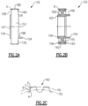
- Figures 2A and 2B show the generator driven gear 152 having a body 153 extending from a first end 154 to a second end 156.
- An enlarged disc 155 extends outwardly of a boss 167 extending between the disc 155 and the second end 156.
- Disc 155 has outer gear teeth 162 at an outer diameter O of disc 155.
- a pair of tabs extend from the enlarged disc 155 to the first end 154. Teeth 162 are driven by the ring gear, as mentioned above.
- Figure 2C shows a profile of gear teeth 162.
- the gear teeth have a pitch diameter PD.
- the pitch diameter is 3.50 inches (8.89 centimeters). This and all dimensions have a tolerance of +/- the 0.01 inch (.025 centimeter).
- a maximum form diameter FD is 3.40 inches (8.64 centimeters).
- the profile of the gear teeth is defined by roll angles at points A, B, C, and D. It should be understood specific roll angles of this disclosed gear are novel. All that is known in the art is the specific location of the points A-D.
- the roll angle at A was 14.95 degrees and in embodiments between 14.2 and 15.7 degrees.
- the roll angle at B was 16.96 degrees and in embodiments between 16.2 and 17.7 degrees.
- the roll angle at C was 23.01 degrees and in embodiments between 22.3 and 23.8 degrees.
- the roll angle at D was 25.03 degrees and in embodiments between 24.3 and 25.8 degrees.
- the roll angle at A may be applied at the form diameter FD.
- the roll angle at B is 20 percent away from roll angle at A and between roll angle at A and roll angle at D.
- the roll angle at C is 80 percent away from roll angle at A and between roll angle at A and roll angle at D.
- the roll angle at D is at the outer diameter of the gear tooth.
- gear teeth 162 there are 70 gear teeth 162.
- a method of replacing a generator driven gear includes removing an existing generator driven gear from an integrated drive generator.
- the integrated drive generator has an input shaft and a gear differential including a carrier shaft.
- the gear differential includes a ring gear connected to the existing generator driven gear.
- the method also includes the step of replacing the existing generator driven gear with a replacement generator driven gear.
- the replacement generator driven gear includes a gear body extending between a first end and a second end and having a disc extending radially outwardly of a boss that extends between the first and second ends. Outer gear teeth are formed outwardly of an outer diameter of the disc.
Landscapes
- Engineering & Computer Science (AREA)
- General Engineering & Computer Science (AREA)
- Mechanical Engineering (AREA)
- Chemical & Material Sciences (AREA)
- Combustion & Propulsion (AREA)
- Retarders (AREA)
Description
- This application relates to an integrated drive generator and a method of replacing a generator driven gear for an integrated drive generator.
- Integrated drive generators are known and often utilized in aircraft. As known, a gas turbine engine on the aircraft provides a drive input into a generator input shaft. The generator typically includes a disconnect shaft that can transmit the input into a gear differential. The gear differential selectively drives a main generator and its generator driven gear to provide electric power for various uses on the aircraft.
- It is desirable that the generated power be of a desired constant frequency. However, the speed from the input shaft will vary during operation of the gas turbine engine. This would result in variable frequency.
- Integrated drive generators are provided with speed trimming hydraulic units. Gears associated with the differential and, in particular, a ring gear portion, provide rotation from the differential back into the trimming unit. A carrier also rotates another portion of the trimming unit. The trimming unit is operable to result in the output speed of the differential being effectively constant, such that electric power of a desirable frequency is generated.
- The generator is mounted between two housing portions and a seal plate is mounted between the two housing portions.
- In addition, various accessory systems, such as various pumps, are driven by the output ring gear of the differential through an accessory drive gear. Two such pumps are scavenge and charge pumps. A drive gear drives these pumps.
- The generator driven gear must successfully provide rotational input to a generator rotor. There are challenges with regard to this driven gear.
US 2013/0068057 A1 describes an idler gear assembly for a generator. - An integrated drive generator and a method are defined in the appended claims.
- These and other features may be best understood from the following drawings and specification.
-
-
Figure 1 schematically shows an integrated drive generator. -
Figure 2A shows a generator driven gear. -
Figure 2B shows a cross-sectional view. -
Figure 2C shows a gear tooth profile. -
Figure 1 shows anintegrated drive generator 20. As shown,housing portions seal plate 17 sits between thehousing portions - A
gas turbine engine 22 may drive aninput shaft 23 which selectively drives adisconnect assembly 26. Thedisconnect assembly 26, in turn, drives acarrier shaft 28, which drives a carrier in agear differential 30. - As the
carrier shaft 28 rotates,planet gears gear interface 42 with a firstring gear portion 40. Gears 36 have a gear interface 48 with a second ring gear portion 46. -
Ring gear portion 40 has agear interface 50 with a main generator 51 and its drivengear 152. When drivengear 152 is driven to rotate, it rotates arotor 56 associated with astator 58 of the main generator as well as anexciter rotor 60. Electric power is generated for ause 62, as known. - It is desirable that the frequency of the generated electric power be at a desired frequency. This requires the input speed to
gear 152 to be relatively constant and at the desired speed. As such, the speed of theinput shaft 23 is added to the speed of thespeed trimmer 66 to result in a constant input speed togear 152. - A
gear 15 that is part of the carrier has agear interface 16 with agear 13 driving ashaft 14 also within the speed trimmer. - As known, the
speed trimmer 66 includes avariable unit 72 and afixed unit 76. Theunits gear 13 is too high, the speed of thegear 152 will also be too high, and hence, the speed trimmer 66 acts to lower the speed of the trim gear 46 which will drop the speed ofgear 152. On the other hand, if the input speed is too low, the speed trimmer will increase the trim gear speed and he speed seen bygear 152 will increase. - In essence, the
variable unit 72 receives an input throughgear 13 that is proportional to the speed of theinput shaft 23. Thevariable unit 72 also receives a control input from a control monitoring the speed of thegenerator rotor 56. The position of the swash plate in thevariable unit 72 is changed to in turn change the speed and direction of thefixed unit 76. Thefixed unit 76 can change the speed, and direction of rotation of theshaft 70, and this then provides control back through the trim ring gear 46 to change the speed reaching the generator. In this manner, the speed trimmer 66 results in the frequency generated by the generator being closer to constant, and at the desired frequency. - A
permanent magnet generator 32 rotates with thering gear 40. - An
accessory drive shaft 29 rotates with thering gear 40 and drives a plurality ofaccessory gears 31. - The operation of the integrated
drive generator 20 is generally as known in the art. The generator drivengear 152 is unique as set forth below. A worker of ordinary skill would recognize that the desired frequency and speed atuse 62 would dictate a number of design functions. -
Figures 2A and 2B show the generator drivengear 152 having abody 153 extending from afirst end 154 to asecond end 156. An enlargeddisc 155 extends outwardly of aboss 167 extending between thedisc 155 and thesecond end 156.Disc 155 hasouter gear teeth 162 at an outer diameter O ofdisc 155. A pair of tabs extend from the enlargeddisc 155 to thefirst end 154.Teeth 162 are driven by the ring gear, as mentioned above. -
Figure 2C shows a profile ofgear teeth 162. The gear teeth have a pitch diameter PD. In one embodiment, the pitch diameter is 3.50 inches (8.89 centimeters). This and all dimensions have a tolerance of +/- the 0.01 inch (.025 centimeter). - A maximum form diameter FD is 3.40 inches (8.64 centimeters).
- As known in the gear tooth art, the profile of the gear teeth is defined by roll angles at points A, B, C, and D. It should be understood specific roll angles of this disclosed gear are novel. All that is known in the art is the specific location of the points A-D. In a disclosed embodiment, the roll angle at A was 14.95 degrees and in embodiments between 14.2 and 15.7 degrees. The roll angle at B was 16.96 degrees and in embodiments between 16.2 and 17.7 degrees. The roll angle at C was 23.01 degrees and in embodiments between 22.3 and 23.8 degrees. The roll angle at D was 25.03 degrees and in embodiments between 24.3 and 25.8 degrees.
- The roll angle at A may be applied at the form diameter FD. The roll angle at B is 20 percent away from roll angle at A and between roll angle at A and roll angle at D. The roll angle at C is 80 percent away from roll angle at A and between roll angle at A and roll angle at D. The roll angle at D is at the outer diameter of the gear tooth.
- In embodiments, there are 70
gear teeth 162. - A method of replacing a generator driven gear includes removing an existing generator driven gear from an integrated drive generator. The integrated drive generator has an input shaft and a gear differential including a carrier shaft. The gear differential includes a ring gear connected to the existing generator driven gear. The method also includes the step of replacing the existing generator driven gear with a replacement generator driven gear. The replacement generator driven gear includes a gear body extending between a first end and a second end and having a disc extending radially outwardly of a boss that extends between the first and second ends. Outer gear teeth are formed outwardly of an outer diameter of the disc. The outer gear teeth have a gear tooth profile with roll angles at A, B, C, and D, and the roll angle at A being between 14.2 and 15.7 degrees, the roll angle at B being between 16.2 and 17.7 degrees, the roll angle at C being between 22.3 and 23.8 degrees, and the roll angle at D being between 24.3 and 25.8 degrees.
- Although an embodiment of this invention has been disclosed, a worker of ordinary skill in this art would recognize that certain modifications would come within the scope of the following claims.
Claims (2)
- An integrated drive generator comprising:an input shaft;a generator driven gear (152);a gear differential (30) including a carrier shaft connected to said input shaft and including a ring gear (40, 50) connected to the generator driven gear; the generator driven gear comprising:a gear body (153) extending between a first end (154) and a second end (156) and having a disc (155) extending radially outwardly of a boss (167) that extends to said second end, with a pair of tabs (166) extending from the disc to said fist end, there being outer gear teeth outwardly of an outer diameter of said disc, said outer gear teeth having a gear tooth profile with roll angles at points A, B, C, and D, and the roll angle at A for said outer gear teeth being between 14.2 and 15.7 degrees, the roll angle at B for said outer gear teeth being between 16.2 and 17.7 degrees, the roll angle at C for said outer gear teeth being between 22.3 and 23.8 degrees, and the roll angle at D for said outer gear teeth being between 24.3 and 25.8 degrees, whereinsaid outer gear teeth have a pitch diameter of 8.89 centimeters (3.50 inches) with a tolerance of +/- 0.025 centimeter (0.01 inch), wherein there are 70 of said outer gear teeth, wherein said outer gear teeth have a maximum form diameter of 8.64 centimeters (3.40 inches) with a tolerance of +/- 0.025 centimeter (0.01 inch), and wherein there are 70 of said outer gear teeth (162), wherein the roll angle at A is applied at the form diameter, the roll angle at B is 20 percent away from roll angle at A and between roll angle at A and roll angle at D, and wherein the roll angle at C is 80 percent away from roll angle at A and between roll angle A and roll angle D; whereinthe roll angle at D is at the outer diameter of the gear tooth; wherein said outer gear teeth have a pitch diameter of 8.89 centimeters (3.50 inches) with a tolerance of +/.025 centimeter (.01 inch);wherein there are 70 of said outer gear teeth;wherein said outer gear teeth have a maximum form diameter of 8.64 centimeters (3.40 inches) with a tolerance of +/- 0.025 centimeter (0.01 inch);wherein there are 70 of said outer gear teeth (162);
wherein the roll angle at A is 14.95 degrees, the roll angle at B is 16.96 degrees, the roll angle at C is 23.01 degrees and the roll angle at D is 25.03 degrees. - A method of replacing a generator driven gear in the integrated drive generator of claim 1, comprising the steps of:a) removing an existing generator driven gear from an integrated drive generator having an input shaft, a gear differential including a carrier shaft and the gear differential including a ring gear connected to the existing generator driven gear; andb) replacing the existing generator driven gear with a replacement generator driven gear (152)
including a gear body extending between a first end and a second end and having a disc extending radially outwardly of a boss that extends to said second end, with a pair of tabs extending from the disc to said first end, there being outer gear teeth outwardly of an outer diameter of said disc, said outer gear teeth having a gear tooth profile with roll angles at points A, B, C, and D, and the roll angle at A for said outer gear teeth being between 14.2 and 15.7 degrees, the roll angle at B for said outer gear teeth being between 16.2 and 17.7 degrees, the roll angle at C for said outer gear teeth being between 22.3 and 23.8 degrees, and the roll angle at D for said outer gear teeth being between 24.3 and 25.8 degrees and wherein said outer gear teeth have a pitch diameter of 8.89 centimeters (3.50 inches) with a tolerance of +/- 0.025 centimeter (0.01 inch), and wherein there are 70 of said outer gear teeth, and . wherein said outer gear teeth have a maximum form diameter of 8.64 centimeters (3.40 inches) with a tolerance of +/- 0.025 centimeter (0.01 inch), wherein there are 70 of said outer gear teeth (162), wherein the roll angle at A is applied at the form diameter, the roll angle at B is 20 percent away from roll angle at A and between roll angle at A and roll angle at D, and wherein the roll angle at C is 80 percent away from roll angle at A and between roll angle at A and roll angle at D and wherein the roll angle at D is at the outer diameter of the gear tooth; wherein the roll angle at A is 14.95 degrees, the roll angle at B is 16.96 degrees, the roll angle at C is 23.01 degrees and the roll angle at D is 25.03 degrees.
Applications Claiming Priority (1)
| Application Number | Priority Date | Filing Date | Title |
|---|---|---|---|
| US15/862,115 US11054012B2 (en) | 2018-01-04 | 2018-01-04 | Generator driven gear for integrated drive generator |
Publications (2)
| Publication Number | Publication Date |
|---|---|
| EP3508758A1 EP3508758A1 (en) | 2019-07-10 |
| EP3508758B1 true EP3508758B1 (en) | 2024-07-24 |
Family
ID=64949186
Family Applications (1)
| Application Number | Title | Priority Date | Filing Date |
|---|---|---|---|
| EP19150187.3A Active EP3508758B1 (en) | 2018-01-04 | 2019-01-03 | Generator driven gear for integrated drive generator |
Country Status (2)
| Country | Link |
|---|---|
| US (1) | US11054012B2 (en) |
| EP (1) | EP3508758B1 (en) |
Family Cites Families (10)
| Publication number | Priority date | Publication date | Assignee | Title |
|---|---|---|---|---|
| FR2741415B1 (en) * | 1995-11-17 | 1998-01-16 | Faure Bertrand Equipements Sa | COMPACT REDUCER WITH TWO REDUCTION STAGES |
| US8051738B2 (en) * | 2009-05-06 | 2011-11-08 | Hamilton Sundstrand Corporation | Rotor gear for a generator |
| US9057372B2 (en) * | 2010-12-06 | 2015-06-16 | Hamilton Sundstrand Corporation | Gear root geometry for increased carryover volume |
| US20130068057A1 (en) * | 2011-09-16 | 2013-03-21 | Hamilon Sundstrand Corporation | Idler gear assembly for a generator |
| US8890350B2 (en) * | 2012-01-13 | 2014-11-18 | Hamilton Sundstrand Corporation | Turbomachine drive arrangement |
| US20140008170A1 (en) | 2012-07-06 | 2014-01-09 | Henry R. Vanderzyden | Integrated drive generator disconnect assembly |
| US9494225B2 (en) * | 2014-02-17 | 2016-11-15 | Hamilton Sundstrand Corporation | Electric generator oil pump driven gear |
| US9502942B2 (en) * | 2014-02-17 | 2016-11-22 | Hamilton Sundstrand Corporation | Electric generator oil pump drive gear |
| US9470302B1 (en) * | 2015-04-03 | 2016-10-18 | Hamilton Sundstrand Corporation | Accessory drive gear for a differential |
| US9341996B1 (en) | 2015-04-09 | 2016-05-17 | Lexmark International, Inc. | Hub-based drive coupling mechanism for a fuser backup member and methods of using same |
-
2018
- 2018-01-04 US US15/862,115 patent/US11054012B2/en active Active
-
2019
- 2019-01-03 EP EP19150187.3A patent/EP3508758B1/en active Active
Also Published As
| Publication number | Publication date |
|---|---|
| US20190203821A1 (en) | 2019-07-04 |
| US11054012B2 (en) | 2021-07-06 |
| EP3508758A1 (en) | 2019-07-10 |
Similar Documents
| Publication | Publication Date | Title |
|---|---|---|
| EP3486528B1 (en) | Governor and inversion pump drive gear | |
| EP3508746B1 (en) | Input shaft for use in integrated drive gear | |
| EP3509199B1 (en) | Main generator stator sleeve for integrated drive generator | |
| EP3467331B1 (en) | Disconnect shaft for integrated drive generator | |
| EP3467350A1 (en) | Trim ring gear for integrated drive generator | |
| EP3508758B1 (en) | Generator driven gear for integrated drive generator | |
| EP3514398B1 (en) | Fixed block shaft inner bearing race for integrated drive generator | |
| EP3483443B1 (en) | Pump sleeve for integrated drive generator | |
| EP3467349B1 (en) | Accessory drive gear for integrated drive generator | |
| EP3486529B1 (en) | Scavenge/charge pump drive gear for integrated drive generator | |
| EP3508757B1 (en) | Integrated drive generator and related method for replacing a governor drive gear therein | |
| EP3511594B1 (en) | Fixed block shaft for integrated drive generator | |
| EP3514324B1 (en) | Cam liner for integrated drive generator | |
| EP3502514B1 (en) | Output ring gear for integrated drive generator | |
| EP3490111B1 (en) | Permanent magnet generator rotor for integrated drive generator | |
| EP3511595B1 (en) | Variable block shaft for integrated drive generator | |
| EP3489532B1 (en) | Wear ring for integrated drive generator |
Legal Events
| Date | Code | Title | Description |
|---|---|---|---|
| PUAI | Public reference made under article 153(3) epc to a published international application that has entered the european phase |
Free format text: ORIGINAL CODE: 0009012 |
|
| STAA | Information on the status of an ep patent application or granted ep patent |
Free format text: STATUS: THE APPLICATION HAS BEEN PUBLISHED |
|
| AK | Designated contracting states |
Kind code of ref document: A1 Designated state(s): AL AT BE BG CH CY CZ DE DK EE ES FI FR GB GR HR HU IE IS IT LI LT LU LV MC MK MT NL NO PL PT RO RS SE SI SK SM TR |
|
| AX | Request for extension of the european patent |
Extension state: BA ME |
|
| STAA | Information on the status of an ep patent application or granted ep patent |
Free format text: STATUS: REQUEST FOR EXAMINATION WAS MADE |
|
| 17P | Request for examination filed |
Effective date: 20191126 |
|
| RBV | Designated contracting states (corrected) |
Designated state(s): AL AT BE BG CH CY CZ DE DK EE ES FI FR GB GR HR HU IE IS IT LI LT LU LV MC MK MT NL NO PL PT RO RS SE SI SK SM TR |
|
| STAA | Information on the status of an ep patent application or granted ep patent |
Free format text: STATUS: EXAMINATION IS IN PROGRESS |
|
| 17Q | First examination report despatched |
Effective date: 20201013 |
|
| GRAP | Despatch of communication of intention to grant a patent |
Free format text: ORIGINAL CODE: EPIDOSNIGR1 |
|
| STAA | Information on the status of an ep patent application or granted ep patent |
Free format text: STATUS: GRANT OF PATENT IS INTENDED |
|
| RIC1 | Information provided on ipc code assigned before grant |
Ipc: F02C 7/36 20060101ALI20240215BHEP Ipc: F16H 55/17 20060101AFI20240215BHEP |
|
| INTG | Intention to grant announced |
Effective date: 20240301 |
|
| GRAS | Grant fee paid |
Free format text: ORIGINAL CODE: EPIDOSNIGR3 |
|
| GRAA | (expected) grant |
Free format text: ORIGINAL CODE: 0009210 |
|
| STAA | Information on the status of an ep patent application or granted ep patent |
Free format text: STATUS: THE PATENT HAS BEEN GRANTED |
|
| AK | Designated contracting states |
Kind code of ref document: B1 Designated state(s): AL AT BE BG CH CY CZ DE DK EE ES FI FR GB GR HR HU IE IS IT LI LT LU LV MC MK MT NL NO PL PT RO RS SE SI SK SM TR |
|
| REG | Reference to a national code |
Ref country code: GB Ref legal event code: FG4D |
|
| REG | Reference to a national code |
Ref country code: CH Ref legal event code: EP |
|
| REG | Reference to a national code |
Ref country code: IE Ref legal event code: FG4D Ref country code: DE Ref legal event code: R096 Ref document number: 602019055588 Country of ref document: DE |
|
| REG | Reference to a national code |
Ref country code: LT Ref legal event code: MG9D |
|
| REG | Reference to a national code |
Ref country code: NL Ref legal event code: MP Effective date: 20240724 |
|
| PG25 | Lapsed in a contracting state [announced via postgrant information from national office to epo] |
Ref country code: PT Free format text: LAPSE BECAUSE OF FAILURE TO SUBMIT A TRANSLATION OF THE DESCRIPTION OR TO PAY THE FEE WITHIN THE PRESCRIBED TIME-LIMIT Effective date: 20241125 |
|
| REG | Reference to a national code |
Ref country code: AT Ref legal event code: MK05 Ref document number: 1706554 Country of ref document: AT Kind code of ref document: T Effective date: 20240724 |
|
| PG25 | Lapsed in a contracting state [announced via postgrant information from national office to epo] |
Ref country code: NL Free format text: LAPSE BECAUSE OF FAILURE TO SUBMIT A TRANSLATION OF THE DESCRIPTION OR TO PAY THE FEE WITHIN THE PRESCRIBED TIME-LIMIT Effective date: 20240724 |
|
| PG25 | Lapsed in a contracting state [announced via postgrant information from national office to epo] |
Ref country code: PT Free format text: LAPSE BECAUSE OF FAILURE TO SUBMIT A TRANSLATION OF THE DESCRIPTION OR TO PAY THE FEE WITHIN THE PRESCRIBED TIME-LIMIT Effective date: 20241125 Ref country code: NL Free format text: LAPSE BECAUSE OF FAILURE TO SUBMIT A TRANSLATION OF THE DESCRIPTION OR TO PAY THE FEE WITHIN THE PRESCRIBED TIME-LIMIT Effective date: 20240724 |
|
| PG25 | Lapsed in a contracting state [announced via postgrant information from national office to epo] |
Ref country code: NO Free format text: LAPSE BECAUSE OF FAILURE TO SUBMIT A TRANSLATION OF THE DESCRIPTION OR TO PAY THE FEE WITHIN THE PRESCRIBED TIME-LIMIT Effective date: 20241024 |
|
| PG25 | Lapsed in a contracting state [announced via postgrant information from national office to epo] |
Ref country code: PL Free format text: LAPSE BECAUSE OF FAILURE TO SUBMIT A TRANSLATION OF THE DESCRIPTION OR TO PAY THE FEE WITHIN THE PRESCRIBED TIME-LIMIT Effective date: 20240724 Ref country code: FI Free format text: LAPSE BECAUSE OF FAILURE TO SUBMIT A TRANSLATION OF THE DESCRIPTION OR TO PAY THE FEE WITHIN THE PRESCRIBED TIME-LIMIT Effective date: 20240724 Ref country code: GR Free format text: LAPSE BECAUSE OF FAILURE TO SUBMIT A TRANSLATION OF THE DESCRIPTION OR TO PAY THE FEE WITHIN THE PRESCRIBED TIME-LIMIT Effective date: 20241025 |
|
| PG25 | Lapsed in a contracting state [announced via postgrant information from national office to epo] |
Ref country code: BG Free format text: LAPSE BECAUSE OF FAILURE TO SUBMIT A TRANSLATION OF THE DESCRIPTION OR TO PAY THE FEE WITHIN THE PRESCRIBED TIME-LIMIT Effective date: 20240724 |
|
| PG25 | Lapsed in a contracting state [announced via postgrant information from national office to epo] |
Ref country code: LV Free format text: LAPSE BECAUSE OF FAILURE TO SUBMIT A TRANSLATION OF THE DESCRIPTION OR TO PAY THE FEE WITHIN THE PRESCRIBED TIME-LIMIT Effective date: 20240724 |
|
| PG25 | Lapsed in a contracting state [announced via postgrant information from national office to epo] |
Ref country code: AT Free format text: LAPSE BECAUSE OF FAILURE TO SUBMIT A TRANSLATION OF THE DESCRIPTION OR TO PAY THE FEE WITHIN THE PRESCRIBED TIME-LIMIT Effective date: 20240724 Ref country code: IS Free format text: LAPSE BECAUSE OF FAILURE TO SUBMIT A TRANSLATION OF THE DESCRIPTION OR TO PAY THE FEE WITHIN THE PRESCRIBED TIME-LIMIT Effective date: 20241124 |
|
| PG25 | Lapsed in a contracting state [announced via postgrant information from national office to epo] |
Ref country code: HR Free format text: LAPSE BECAUSE OF FAILURE TO SUBMIT A TRANSLATION OF THE DESCRIPTION OR TO PAY THE FEE WITHIN THE PRESCRIBED TIME-LIMIT Effective date: 20240724 |
|
| PG25 | Lapsed in a contracting state [announced via postgrant information from national office to epo] |
Ref country code: RS Free format text: LAPSE BECAUSE OF FAILURE TO SUBMIT A TRANSLATION OF THE DESCRIPTION OR TO PAY THE FEE WITHIN THE PRESCRIBED TIME-LIMIT Effective date: 20241024 Ref country code: ES Free format text: LAPSE BECAUSE OF FAILURE TO SUBMIT A TRANSLATION OF THE DESCRIPTION OR TO PAY THE FEE WITHIN THE PRESCRIBED TIME-LIMIT Effective date: 20240724 |
|
| PG25 | Lapsed in a contracting state [announced via postgrant information from national office to epo] |
Ref country code: RS Free format text: LAPSE BECAUSE OF FAILURE TO SUBMIT A TRANSLATION OF THE DESCRIPTION OR TO PAY THE FEE WITHIN THE PRESCRIBED TIME-LIMIT Effective date: 20241024 Ref country code: PL Free format text: LAPSE BECAUSE OF FAILURE TO SUBMIT A TRANSLATION OF THE DESCRIPTION OR TO PAY THE FEE WITHIN THE PRESCRIBED TIME-LIMIT Effective date: 20240724 Ref country code: NO Free format text: LAPSE BECAUSE OF FAILURE TO SUBMIT A TRANSLATION OF THE DESCRIPTION OR TO PAY THE FEE WITHIN THE PRESCRIBED TIME-LIMIT Effective date: 20241024 Ref country code: LV Free format text: LAPSE BECAUSE OF FAILURE TO SUBMIT A TRANSLATION OF THE DESCRIPTION OR TO PAY THE FEE WITHIN THE PRESCRIBED TIME-LIMIT Effective date: 20240724 Ref country code: IS Free format text: LAPSE BECAUSE OF FAILURE TO SUBMIT A TRANSLATION OF THE DESCRIPTION OR TO PAY THE FEE WITHIN THE PRESCRIBED TIME-LIMIT Effective date: 20241124 Ref country code: HR Free format text: LAPSE BECAUSE OF FAILURE TO SUBMIT A TRANSLATION OF THE DESCRIPTION OR TO PAY THE FEE WITHIN THE PRESCRIBED TIME-LIMIT Effective date: 20240724 Ref country code: GR Free format text: LAPSE BECAUSE OF FAILURE TO SUBMIT A TRANSLATION OF THE DESCRIPTION OR TO PAY THE FEE WITHIN THE PRESCRIBED TIME-LIMIT Effective date: 20241025 Ref country code: FI Free format text: LAPSE BECAUSE OF FAILURE TO SUBMIT A TRANSLATION OF THE DESCRIPTION OR TO PAY THE FEE WITHIN THE PRESCRIBED TIME-LIMIT Effective date: 20240724 Ref country code: ES Free format text: LAPSE BECAUSE OF FAILURE TO SUBMIT A TRANSLATION OF THE DESCRIPTION OR TO PAY THE FEE WITHIN THE PRESCRIBED TIME-LIMIT Effective date: 20240724 Ref country code: BG Free format text: LAPSE BECAUSE OF FAILURE TO SUBMIT A TRANSLATION OF THE DESCRIPTION OR TO PAY THE FEE WITHIN THE PRESCRIBED TIME-LIMIT Effective date: 20240724 Ref country code: AT Free format text: LAPSE BECAUSE OF FAILURE TO SUBMIT A TRANSLATION OF THE DESCRIPTION OR TO PAY THE FEE WITHIN THE PRESCRIBED TIME-LIMIT Effective date: 20240724 |
|
| PG25 | Lapsed in a contracting state [announced via postgrant information from national office to epo] |
Ref country code: SM Free format text: LAPSE BECAUSE OF FAILURE TO SUBMIT A TRANSLATION OF THE DESCRIPTION OR TO PAY THE FEE WITHIN THE PRESCRIBED TIME-LIMIT Effective date: 20240724 Ref country code: DK Free format text: LAPSE BECAUSE OF FAILURE TO SUBMIT A TRANSLATION OF THE DESCRIPTION OR TO PAY THE FEE WITHIN THE PRESCRIBED TIME-LIMIT Effective date: 20240724 Ref country code: RO Free format text: LAPSE BECAUSE OF FAILURE TO SUBMIT A TRANSLATION OF THE DESCRIPTION OR TO PAY THE FEE WITHIN THE PRESCRIBED TIME-LIMIT Effective date: 20240724 |
|
| PG25 | Lapsed in a contracting state [announced via postgrant information from national office to epo] |
Ref country code: EE Free format text: LAPSE BECAUSE OF FAILURE TO SUBMIT A TRANSLATION OF THE DESCRIPTION OR TO PAY THE FEE WITHIN THE PRESCRIBED TIME-LIMIT Effective date: 20240724 |
|
| PG25 | Lapsed in a contracting state [announced via postgrant information from national office to epo] |
Ref country code: CZ Free format text: LAPSE BECAUSE OF FAILURE TO SUBMIT A TRANSLATION OF THE DESCRIPTION OR TO PAY THE FEE WITHIN THE PRESCRIBED TIME-LIMIT Effective date: 20240724 |
|
| REG | Reference to a national code |
Ref country code: DE Ref legal event code: R097 Ref document number: 602019055588 Country of ref document: DE |
|
| PG25 | Lapsed in a contracting state [announced via postgrant information from national office to epo] |
Ref country code: SK Free format text: LAPSE BECAUSE OF FAILURE TO SUBMIT A TRANSLATION OF THE DESCRIPTION OR TO PAY THE FEE WITHIN THE PRESCRIBED TIME-LIMIT Effective date: 20240724 Ref country code: IT Free format text: LAPSE BECAUSE OF FAILURE TO SUBMIT A TRANSLATION OF THE DESCRIPTION OR TO PAY THE FEE WITHIN THE PRESCRIBED TIME-LIMIT Effective date: 20240724 |
|
| PLBE | No opposition filed within time limit |
Free format text: ORIGINAL CODE: 0009261 |
|
| STAA | Information on the status of an ep patent application or granted ep patent |
Free format text: STATUS: NO OPPOSITION FILED WITHIN TIME LIMIT |
|
| 26N | No opposition filed |
Effective date: 20250425 |
|
| REG | Reference to a national code |
Ref country code: CH Ref legal event code: PL |
|
| PG25 | Lapsed in a contracting state [announced via postgrant information from national office to epo] |
Ref country code: SE Free format text: LAPSE BECAUSE OF FAILURE TO SUBMIT A TRANSLATION OF THE DESCRIPTION OR TO PAY THE FEE WITHIN THE PRESCRIBED TIME-LIMIT Effective date: 20240724 |
|
| PG25 | Lapsed in a contracting state [announced via postgrant information from national office to epo] |
Ref country code: MC Free format text: LAPSE BECAUSE OF FAILURE TO SUBMIT A TRANSLATION OF THE DESCRIPTION OR TO PAY THE FEE WITHIN THE PRESCRIBED TIME-LIMIT Effective date: 20240724 Ref country code: LU Free format text: LAPSE BECAUSE OF NON-PAYMENT OF DUE FEES Effective date: 20250103 |
|
| PG25 | Lapsed in a contracting state [announced via postgrant information from national office to epo] |
Ref country code: BE Free format text: LAPSE BECAUSE OF NON-PAYMENT OF DUE FEES Effective date: 20250131 |
|
| PG25 | Lapsed in a contracting state [announced via postgrant information from national office to epo] |
Ref country code: CH Free format text: LAPSE BECAUSE OF NON-PAYMENT OF DUE FEES Effective date: 20250131 |
|
| REG | Reference to a national code |
Ref country code: BE Ref legal event code: MM Effective date: 20250131 |
|
| PGFP | Annual fee paid to national office [announced via postgrant information from national office to epo] |
Ref country code: GB Payment date: 20251219 Year of fee payment: 8 |
|
| PGFP | Annual fee paid to national office [announced via postgrant information from national office to epo] |
Ref country code: FR Payment date: 20251217 Year of fee payment: 8 |
|
| PG25 | Lapsed in a contracting state [announced via postgrant information from national office to epo] |
Ref country code: IE Free format text: LAPSE BECAUSE OF NON-PAYMENT OF DUE FEES Effective date: 20250103 |
|
| PGFP | Annual fee paid to national office [announced via postgrant information from national office to epo] |
Ref country code: DE Payment date: 20251217 Year of fee payment: 8 |