EP3508756B1 - Linear actuator - Google Patents
Linear actuator Download PDFInfo
- Publication number
- EP3508756B1 EP3508756B1 EP18214210.9A EP18214210A EP3508756B1 EP 3508756 B1 EP3508756 B1 EP 3508756B1 EP 18214210 A EP18214210 A EP 18214210A EP 3508756 B1 EP3508756 B1 EP 3508756B1
- Authority
- EP
- European Patent Office
- Prior art keywords
- linear actuator
- motors
- sun wheel
- motor housing
- screw
- Prior art date
- Legal status (The legal status is an assumption and is not a legal conclusion. Google has not performed a legal analysis and makes no representation as to the accuracy of the status listed.)
- Active
Links
Images


Classifications
-
- F—MECHANICAL ENGINEERING; LIGHTING; HEATING; WEAPONS; BLASTING
- F16—ENGINEERING ELEMENTS AND UNITS; GENERAL MEASURES FOR PRODUCING AND MAINTAINING EFFECTIVE FUNCTIONING OF MACHINES OR INSTALLATIONS; THERMAL INSULATION IN GENERAL
- F16H—GEARING
- F16H25/00—Gearings comprising primarily only cams, cam-followers and screw-and-nut mechanisms
- F16H25/18—Gearings comprising primarily only cams, cam-followers and screw-and-nut mechanisms for conveying or interconverting oscillating or reciprocating motions
- F16H25/20—Screw mechanisms
- F16H25/22—Screw mechanisms with balls, rollers, or similar members between the co-operating parts; Elements essential to the use of such members
- F16H25/2247—Screw mechanisms with balls, rollers, or similar members between the co-operating parts; Elements essential to the use of such members with rollers
- F16H25/2252—Planetary rollers between nut and screw
-
- F—MECHANICAL ENGINEERING; LIGHTING; HEATING; WEAPONS; BLASTING
- F16—ENGINEERING ELEMENTS AND UNITS; GENERAL MEASURES FOR PRODUCING AND MAINTAINING EFFECTIVE FUNCTIONING OF MACHINES OR INSTALLATIONS; THERMAL INSULATION IN GENERAL
- F16H—GEARING
- F16H25/00—Gearings comprising primarily only cams, cam-followers and screw-and-nut mechanisms
- F16H25/18—Gearings comprising primarily only cams, cam-followers and screw-and-nut mechanisms for conveying or interconverting oscillating or reciprocating motions
- F16H25/20—Screw mechanisms
-
- F—MECHANICAL ENGINEERING; LIGHTING; HEATING; WEAPONS; BLASTING
- F02—COMBUSTION ENGINES; HOT-GAS OR COMBUSTION-PRODUCT ENGINE PLANTS
- F02K—JET-PROPULSION PLANTS
- F02K1/00—Plants characterised by the form or arrangement of the jet pipe or nozzle; Jet pipes or nozzles peculiar thereto
- F02K1/54—Nozzles having means for reversing jet thrust
- F02K1/76—Control or regulation of thrust reversers
- F02K1/763—Control or regulation of thrust reversers with actuating systems or actuating devices; Arrangement of actuators for thrust reversers
-
- F—MECHANICAL ENGINEERING; LIGHTING; HEATING; WEAPONS; BLASTING
- F16—ENGINEERING ELEMENTS AND UNITS; GENERAL MEASURES FOR PRODUCING AND MAINTAINING EFFECTIVE FUNCTIONING OF MACHINES OR INSTALLATIONS; THERMAL INSULATION IN GENERAL
- F16H—GEARING
- F16H37/00—Combinations of mechanical gearings, not provided for in groups F16H1/00 - F16H35/00
- F16H37/02—Combinations of mechanical gearings, not provided for in groups F16H1/00 - F16H35/00 comprising essentially only toothed or friction gearings
- F16H37/06—Combinations of mechanical gearings, not provided for in groups F16H1/00 - F16H35/00 comprising essentially only toothed or friction gearings with a plurality of driving or driven shafts; with arrangements for dividing torque between two or more intermediate shafts
- F16H37/065—Combinations of mechanical gearings, not provided for in groups F16H1/00 - F16H35/00 comprising essentially only toothed or friction gearings with a plurality of driving or driven shafts; with arrangements for dividing torque between two or more intermediate shafts with a plurality of driving or driven shafts
-
- F—MECHANICAL ENGINEERING; LIGHTING; HEATING; WEAPONS; BLASTING
- F16—ENGINEERING ELEMENTS AND UNITS; GENERAL MEASURES FOR PRODUCING AND MAINTAINING EFFECTIVE FUNCTIONING OF MACHINES OR INSTALLATIONS; THERMAL INSULATION IN GENERAL
- F16H—GEARING
- F16H37/00—Combinations of mechanical gearings, not provided for in groups F16H1/00 - F16H35/00
- F16H37/02—Combinations of mechanical gearings, not provided for in groups F16H1/00 - F16H35/00 comprising essentially only toothed or friction gearings
- F16H37/06—Combinations of mechanical gearings, not provided for in groups F16H1/00 - F16H35/00 comprising essentially only toothed or friction gearings with a plurality of driving or driven shafts; with arrangements for dividing torque between two or more intermediate shafts
- F16H37/08—Combinations of mechanical gearings, not provided for in groups F16H1/00 - F16H35/00 comprising essentially only toothed or friction gearings with a plurality of driving or driven shafts; with arrangements for dividing torque between two or more intermediate shafts with differential gearing
- F16H37/0806—Combinations of mechanical gearings, not provided for in groups F16H1/00 - F16H35/00 comprising essentially only toothed or friction gearings with a plurality of driving or driven shafts; with arrangements for dividing torque between two or more intermediate shafts with differential gearing with a plurality of driving or driven shafts
- F16H37/0826—Combinations of mechanical gearings, not provided for in groups F16H1/00 - F16H35/00 comprising essentially only toothed or friction gearings with a plurality of driving or driven shafts; with arrangements for dividing torque between two or more intermediate shafts with differential gearing with a plurality of driving or driven shafts with only one output shaft
-
- H—ELECTRICITY
- H02—GENERATION; CONVERSION OR DISTRIBUTION OF ELECTRIC POWER
- H02K—DYNAMO-ELECTRIC MACHINES
- H02K7/00—Arrangements for handling mechanical energy structurally associated with dynamo-electric machines, e.g. structural association with mechanical driving motors or auxiliary dynamo-electric machines
- H02K7/06—Means for converting reciprocating motion into rotary motion or vice versa
-
- F—MECHANICAL ENGINEERING; LIGHTING; HEATING; WEAPONS; BLASTING
- F16—ENGINEERING ELEMENTS AND UNITS; GENERAL MEASURES FOR PRODUCING AND MAINTAINING EFFECTIVE FUNCTIONING OF MACHINES OR INSTALLATIONS; THERMAL INSULATION IN GENERAL
- F16H—GEARING
- F16H25/00—Gearings comprising primarily only cams, cam-followers and screw-and-nut mechanisms
- F16H25/18—Gearings comprising primarily only cams, cam-followers and screw-and-nut mechanisms for conveying or interconverting oscillating or reciprocating motions
- F16H25/20—Screw mechanisms
- F16H2025/2062—Arrangements for driving the actuator
-
- F—MECHANICAL ENGINEERING; LIGHTING; HEATING; WEAPONS; BLASTING
- F16—ENGINEERING ELEMENTS AND UNITS; GENERAL MEASURES FOR PRODUCING AND MAINTAINING EFFECTIVE FUNCTIONING OF MACHINES OR INSTALLATIONS; THERMAL INSULATION IN GENERAL
- F16H—GEARING
- F16H25/00—Gearings comprising primarily only cams, cam-followers and screw-and-nut mechanisms
- F16H25/18—Gearings comprising primarily only cams, cam-followers and screw-and-nut mechanisms for conveying or interconverting oscillating or reciprocating motions
- F16H25/20—Screw mechanisms
- F16H2025/2062—Arrangements for driving the actuator
- F16H2025/2081—Parallel arrangement of drive motor to screw axis
-
- F—MECHANICAL ENGINEERING; LIGHTING; HEATING; WEAPONS; BLASTING
- F16—ENGINEERING ELEMENTS AND UNITS; GENERAL MEASURES FOR PRODUCING AND MAINTAINING EFFECTIVE FUNCTIONING OF MACHINES OR INSTALLATIONS; THERMAL INSULATION IN GENERAL
- F16H—GEARING
- F16H25/00—Gearings comprising primarily only cams, cam-followers and screw-and-nut mechanisms
- F16H25/18—Gearings comprising primarily only cams, cam-followers and screw-and-nut mechanisms for conveying or interconverting oscillating or reciprocating motions
- F16H25/20—Screw mechanisms
- F16H2025/2062—Arrangements for driving the actuator
- F16H2025/2087—Arrangements for driving the actuator using planetary gears
-
- F—MECHANICAL ENGINEERING; LIGHTING; HEATING; WEAPONS; BLASTING
- F16—ENGINEERING ELEMENTS AND UNITS; GENERAL MEASURES FOR PRODUCING AND MAINTAINING EFFECTIVE FUNCTIONING OF MACHINES OR INSTALLATIONS; THERMAL INSULATION IN GENERAL
- F16H—GEARING
- F16H25/00—Gearings comprising primarily only cams, cam-followers and screw-and-nut mechanisms
- F16H25/18—Gearings comprising primarily only cams, cam-followers and screw-and-nut mechanisms for conveying or interconverting oscillating or reciprocating motions
- F16H25/20—Screw mechanisms
- F16H25/2015—Means specially adapted for stopping actuators in the end position; Position sensing means
Definitions
- the present invention relates to a linear actuator.
- Such a linear actuator is shown in the applicant's WO 0125654 .
- US 2007/051847 A1 relates to a linear actuator assembly for use in e.g. aircraft flight surface control system.
- the assembly has a set of motors receiving electrical drive power to supply a drive force, and could, if needed or desired, be implemented with more than two motors.
- the object of the present invention is to provide an improved linear actuator.
- gearboxes Normally a respective reduction gearbox will be connected between each motor its respective planet wheel. Conveniently these gearboxes will be single to double stage epicyclic gearboxes.
- the sun and planet wheels could be toothed wheels drivingly connected by belts, they will normally be gearwheels. This enables them to transmit the output torque of the motors, enhanced by the gearboxes as normally provided. There being a plurality of motors and gearboxes, the torque transmitted to the sun wheel is multiplied by the number of these. There can be as few as three to six and possibly more, for instance twelve or even twenty four, increasing diameter of the housing.
- the sun wheel / planet wheel ratio is greater than 1: 1.5 possibly between 1.5:1 and 4:1, and preferably between 1.75:1 and 3:1. This enhances further the torque applied to the screw for advancing or retracting the inner tube.
- a rolling element bearing is provided for journalling the screw and with it the sun wheel.
- an outer race of the bearing is captivated between the outer tube and a closure member of the housing; whilst an inner race is captivated between the screw and the sun wheel.
- buffers are provided for limiting travel of the nut along the extension screw.
- the buffers are provided between the nut and the inner race and the nut and an end stop on the screw remote from the sun wheel.
- the motors will be electric motors.
- an electrically driven linear actuator 1 has a motor housing 2 having an end fitting 3 with a thrust eye 4.
- the housing comprises an end plate 5 carrying the end fitting, a tubular body 6, a mounting plate 7 and a closure member 8.
- the housing is clamped together by six bolts 9 extending through the end plate to the mounting plate.
- the components of the housing have complementarily machined steps 10 and lips 11, for assuring their concentricity.
- the mounting plate has six recesses 12 from the end plate side, with four respective bores 14 around each recess counter-bored from the other side, for receiving the output ends 15 of six gearboxes 16 and four respective fixture screws (not shown).
- Each gearbox has a respective axially-attached electric motor 17, fixed in place via its gearbox.
- Output shafts 18 from the gearboxes extend through the mounting plate into a recess 19 in the closure member 8. The arrangement places the motors 17, with their gearboxes, around a central axis C of the motor housing.
- the closure member 8 has a central threaded and stepped bore 20,21. Threaded in the bore is an outer tube 22 of an arm 23 of the actuator. At its remote end, the outer tube has a polymeric sealing bush 24 threaded into it. Within the bush extends an inner tube 25 having an end plug 26 with an eye 27. In use, pins in the eyes 4,27 prevent the tubes from rotating with respect to each other.
- the inner end 28 of the inner tube 25 has threaded into it an internally threaded collar 29, otherwise referred to as "a nut".
- a threaded shaft 30 extends centrally of the tubes throughout the extent of the outer tube 22.
- the shaft is otherwise referred to as "a screw”.
- the threaded collar 29 is threadedly engaged with the threaded shaft.
- the innermost end 31 of the shaft is splined and receives a splined bore 32 of a sun gearwheel 33. This is held on the shaft by a bolt 34 and washer 341.
- the sun wheel has an extension 35 with a stepped shoulder 36.
- the shaft has a step 37 with a collar 38 abutting the step 37.
- An inner race 38 of a ball bearing 39 is captive between the shoulder 36 and collar 38.
- the outer race 40 of the bearing is captive between the end of the outer tube, threaded in the bore 20 and the step of the bore 21.
- the output shafts 18 of the gearboxes each carry planet gearwheels 41, which are thereby arranged around the central axis C.
- the planet wheels have bosses 42 engaged in a stabiliser ring 43 and they drivingly engage with the sun wheel.
- Driving of the motors in respective directions drives the threaded shaft / screw 30 and extends or retracts the inner tube by movement of the threaded collar / nut 29 along the thread of the screw 30.
- Buffers 44, 45 are provided at opposite ends of the shaft 30, to allow the stalling current to be detected and the motors stopped in positions corresponding to opposite end of travel of the nut and the inner tube.
- the inner buffer 44 is an elastomeric ring between the collar 38 and a further collar 46.
- the outer buffer is a similar elastomeric ring between two thick washers 47, the outer of which is held fast on the end of the shaft by a bolt 48.
- the actuator is waterproof, including at an electric lead gland 48 in the end plate 5.
Landscapes
- Engineering & Computer Science (AREA)
- General Engineering & Computer Science (AREA)
- Mechanical Engineering (AREA)
- Chemical & Material Sciences (AREA)
- Combustion & Propulsion (AREA)
- Power Engineering (AREA)
- Connection Of Motors, Electrical Generators, Mechanical Devices, And The Like (AREA)
Description
- The present invention relates to a linear actuator.
- It is known to provide a linear actuator, comprising:
- a motor housing having
- one end fitting,
- a motor housed in the motor housing, and
- a reduction gearbox housed in the housing, the motor being connected to a input of the gearbox,
- a telescopic arm, having
- an outer tube attached to the motor housing,
- an inner tube having another end fitting,
- an extension screw contained within the telescopic arm and having
- a driven end journalled at the motor housing end of the outer tube, in driving engagement with the motor and engaging
- a nut fast at the proximal end of the inner tube, rotation of the screw causing the inner tube to extend or retract with respect to the outer tube.
- Such a linear actuator is shown in the applicant's
WO 0125654 US 2007/051847 A1 relates to a linear actuator assembly for use in e.g. aircraft flight surface control system. The assembly has a set of motors receiving electrical drive power to supply a drive force, and could, if needed or desired, be implemented with more than two motors. - The object of the present invention is to provide an improved linear actuator.
- According to the invention there is provided a linear actuator according to claim 1.
- Normally a respective reduction gearbox will be connected between each motor its respective planet wheel. Conveniently these gearboxes will be single to double stage epicyclic gearboxes.
- Whilst it is conceivable that the sun and planet wheels could be toothed wheels drivingly connected by belts, they will normally be gearwheels. This enables them to transmit the output torque of the motors, enhanced by the gearboxes as normally provided. There being a plurality of motors and gearboxes, the torque transmitted to the sun wheel is multiplied by the number of these. There can be as few as three to six and possibly more, for instance twelve or even twenty four, increasing diameter of the housing.
- Conveniently the sun wheel / planet wheel ratio is greater than 1: 1.5 possibly between 1.5:1 and 4:1, and preferably between 1.75:1 and 3:1. This enhances further the torque applied to the screw for advancing or retracting the inner tube.
- It is imaginable that there could be a gear-reduction between the sun wheel and the extension screw. It could a single or double stage epicyclic gearbox in place of such gearboxes between the motors and the planet wheels. It could also be in addition to such gearboxes.
- In the preferred embodiment, where there is a gearbox between each motor and its planet wheel, a rolling element bearing is provided for journalling the screw and with it the sun wheel. Conveniently, an outer race of the bearing is captivated between the outer tube and a closure member of the housing; whilst an inner race is captivated between the screw and the sun wheel.
- Whilst the motors could be carried by in a carrier opposite from the planet wheels, this is unnecessary where gearboxes are provided and made fast in a mounting plate. This arrangement maintains the sun and planet wheels in engagement.
- In case of over-run of the motors, buffers are provided for limiting travel of the nut along the extension screw. Preferably the buffers are provided between the nut and the inner race and the nut and an end stop on the screw remote from the sun wheel.
- Normally the motors will be electric motors.
- To help understanding of the invention, a specific embodiment thereof will now be described by way of example and with reference to the accompanying drawings, in which:
-
Figure 1 is a perspective view of a linear actuator in accordance with the invention; -
Figure 2 is an exploded view of the linear actuator ofFigure 1 ; -
Figure 3 is a central cross-sectional view of the linear actuator ofFigure 1 ; and -
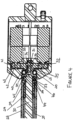
Figure 4 is a more detailed view of the motor housing as shown inFigure 3 . - Referring to the drawings, an electrically driven linear actuator 1 has a
motor housing 2 having an end fitting 3 with athrust eye 4. The housing comprises an end plate 5 carrying the end fitting, a tubular body 6, a mounting plate 7 and a closure member 8. The housing is clamped together by six bolts 9 extending through the end plate to the mounting plate. The components of the housing have complementarilymachined steps 10 and lips 11, for assuring their concentricity. - The mounting plate has six
recesses 12 from the end plate side, with fourrespective bores 14 around each recess counter-bored from the other side, for receiving theoutput ends 15 of sixgearboxes 16 and four respective fixture screws (not shown). Each gearbox has a respective axially-attachedelectric motor 17, fixed in place via its gearbox.Output shafts 18 from the gearboxes extend through the mounting plate into arecess 19 in the closure member 8. The arrangement places themotors 17, with their gearboxes, around a central axis C of the motor housing. - The closure member 8 has a central threaded and stepped bore 20,21. Threaded in the bore is an
outer tube 22 of anarm 23 of the actuator. At its remote end, the outer tube has apolymeric sealing bush 24 threaded into it. Within the bush extends aninner tube 25 having anend plug 26 with aneye 27. In use, pins in theeyes - The
inner end 28 of theinner tube 25 has threaded into it an internally threadedcollar 29, otherwise referred to as "a nut". A threadedshaft 30 extends centrally of the tubes throughout the extent of theouter tube 22. The shaft is otherwise referred to as "a screw". The threadedcollar 29 is threadedly engaged with the threaded shaft. Theinnermost end 31 of the shaft is splined and receives asplined bore 32 of asun gearwheel 33. This is held on the shaft by abolt 34 and washer 341. The sun wheel has anextension 35 with astepped shoulder 36. The shaft has astep 37 with acollar 38 abutting thestep 37. Aninner race 38 of a ball bearing 39 is captive between theshoulder 36 andcollar 38. Theouter race 40 of the bearing is captive between the end of the outer tube, threaded in thebore 20 and the step of thebore 21. Thus the threadedshaft 30 and the sun wheel are located axially. - The
output shafts 18 of the gearboxes each carryplanet gearwheels 41, which are thereby arranged around the central axis C. The planet wheels havebosses 42 engaged in astabiliser ring 43 and they drivingly engage with the sun wheel. Driving of the motors in respective directions drives the threaded shaft /screw 30 and extends or retracts the inner tube by movement of the threaded collar /nut 29 along the thread of thescrew 30. -
Buffers shaft 30, to allow the stalling current to be detected and the motors stopped in positions corresponding to opposite end of travel of the nut and the inner tube. Theinner buffer 44 is an elastomeric ring between thecollar 38 and afurther collar 46. The outer buffer is a similar elastomeric ring between twothick washers 47, the outer of which is held fast on the end of the shaft by abolt 48. When the arm is fully extended, the threaded collar /nut 29 abuts the inner of thewashers 47 to compress the outer buffer. When the inner tube is fully withdrawn, the threaded collar /nut 29 abuts thefurther collar 46 to compress the inner buffer. - All the parts within reason of the actuator and particularly exposed parts are of stainless steel, with the notable exception of the sealing
bush 24. With the joints between the parts sealed, the actuator is waterproof, including at anelectric lead gland 48 in the end plate 5.
Claims (15)
- A linear actuator (1), comprising:• a motor housing (2) having• one end fitting (3),• a telescopic arm, having• an outer tube (22) attached to the motor housing,• an inner tube (25) having another end fitting (26)• an extension screw (30) contained within the telescopic arm and having• a driven end journalled at the motor housing end of the outer tube and engaging• a nut (29) fast at a proximal end of the inner tube, rotation of the extension screw causing the inner tube to extend or retract with respect to the outer tube,wherein• three or more motors are arranged around a central axis;• three or more planet wheels (41) are arranged around the central axis and are drivingly connected to respective ones of the three or more motors:• a sun wheel (33) is provided in driving engagement with the extension screw, the planet wheels (41) being drivingly connected to the sun wheel, the arrangement being such that the motors jointly, rotatingly drive the extension screw for extension or retraction of the inner tube with respect to the outer tube and the motor housing (2), characterised in that the three or more motors are arranged in the same motor housing (2).
- A linear actuator as claimed in claim 1, wherein a respective reduction gearbox (16) is connected between each motor and its respective planet wheel
- A linear actuator as claimed in claim 2, wherein the respective gearboxes are single to double stage epicyclic gearboxes.
- A linear actuator as claimed in claim 2 or claim 3, wherein the motors are carried via the respective reduction gearboxes by a mounting plate (7) in the motor housing
- A linear actuator as claimed in any one of claims 1 to 4, wherein the sun and planet wheels are gearwheels.
- A linear actuator as claimed in claim 1, wherein the planet wheels have bosses (42) engaged in apertures in a stabiliser ring (43) at the sun wheel to hold the planet wheels in mesh with the sun wheel.
- A linear actuator as claimed in any preceding claim, wherein the sun wheel / planet wheel ratio is greater than 1.5:1.
- A linear actuator as claimed in claim 7, wherein the sun wheel / planet wheel ratio is between 1.5:1 and 4:1.
- A linear actuator as claimed in any preceding claim, wherein the sun wheel is fast with the extension screw, a rolling element bearing preferably being provided for journalling the screw and with it the sun wheel.
- A linear actuator as claimed in claim 9, wherein• an outer race (40) of the bearing is captivated between the outer tube and a closure member (8) of the housing and• an inner race (38) is captivated between the screw and the sun wheel.
- A linear actuator as claimed in any one of claims 1 to 8, wherein there is a gear-reduction between the sun wheel and the extension screw.
- A linear actuator as claimed in any preceding claim, including buffers (44, 45) are provided for limiting travel of the nut along the extension screw.
- A linear actuator as claimed in any preceding claim, wherein the motors are electric motors.
- A linear actuator as claimed in any preceding claim, wherein the motor housing is secured by clamp bolt arranged in the motor housing around the central axis between motors.
- A linear actuator as claimed in any preceding claim, including eyes (4, 27) in the end fittings to restrain rotation of the inner tube and nut on driving of the sun wheel and extension screw by the motors.
Applications Claiming Priority (1)
| Application Number | Priority Date | Filing Date | Title |
|---|---|---|---|
| GB1800260.0A GB2569992B (en) | 2018-01-08 | 2018-01-08 | Linear actuator |
Publications (3)
| Publication Number | Publication Date |
|---|---|
| EP3508756A1 EP3508756A1 (en) | 2019-07-10 |
| EP3508756C0 EP3508756C0 (en) | 2024-01-10 |
| EP3508756B1 true EP3508756B1 (en) | 2024-01-10 |
Family
ID=61190313
Family Applications (1)
| Application Number | Title | Priority Date | Filing Date |
|---|---|---|---|
| EP18214210.9A Active EP3508756B1 (en) | 2018-01-08 | 2018-12-19 | Linear actuator |
Country Status (3)
| Country | Link |
|---|---|
| US (1) | US10907711B2 (en) |
| EP (1) | EP3508756B1 (en) |
| GB (1) | GB2569992B (en) |
Families Citing this family (2)
| Publication number | Priority date | Publication date | Assignee | Title |
|---|---|---|---|---|
| CN113507185A (en) * | 2021-07-22 | 2021-10-15 | 北京自动化控制设备研究所 | Dual-redundancy high-power series thrust vector servo mechanism |
| US20240413701A1 (en) * | 2023-06-09 | 2024-12-12 | Schaeffler Technologies AG & Co. KG | Seal for linear actuator |
Family Cites Families (6)
| Publication number | Priority date | Publication date | Assignee | Title |
|---|---|---|---|---|
| US2570327A (en) * | 1946-04-06 | 1951-10-09 | Adiel Y Dodge | Transmission |
| ATE226289T1 (en) * | 1997-11-03 | 2002-11-15 | Honeywell Ag | DEVICE FOR GENERATING A LONGITUDINAL MOVEMENT AND OR A ROTARY MOVEMENT |
| US7140998B2 (en) * | 2004-10-15 | 2006-11-28 | Gear Driving System Co., Ltd. | Device of an improvement on the structure of linear actuator |
| US7560888B2 (en) * | 2005-09-08 | 2009-07-14 | Honeywell International Inc. | Electromechanical actuator including redundant, dissimilar position feedback |
| DE102008047521A1 (en) * | 2008-09-16 | 2010-04-15 | Mbb Palfinger Gmbh | tail lift |
| US9605736B1 (en) * | 2013-05-31 | 2017-03-28 | Rct Systems, Inc. | High temperature electromagnetic actuator |
-
2018
- 2018-01-08 GB GB1800260.0A patent/GB2569992B/en active Active
- 2018-12-19 EP EP18214210.9A patent/EP3508756B1/en active Active
-
2019
- 2019-01-08 US US16/242,319 patent/US10907711B2/en active Active
Also Published As
| Publication number | Publication date |
|---|---|
| GB2569992B (en) | 2022-11-30 |
| GB201800260D0 (en) | 2018-02-21 |
| GB2569992A (en) | 2019-07-10 |
| US20190211907A1 (en) | 2019-07-11 |
| EP3508756A1 (en) | 2019-07-10 |
| EP3508756C0 (en) | 2024-01-10 |
| US10907711B2 (en) | 2021-02-02 |
Similar Documents
| Publication | Publication Date | Title |
|---|---|---|
| US4579012A (en) | Compact electromechanical actuator | |
| US9021903B2 (en) | Linear actuator | |
| EP2169204B1 (en) | Actuator | |
| WO2015117612A2 (en) | Actuator comprising a planetary roller screw | |
| EP3467347B1 (en) | Linear actuator | |
| CN104802183A (en) | Self-locking type robot joint | |
| US10295029B2 (en) | Magnetic damping systems | |
| US20100025610A1 (en) | Low profile valve actuator having high torque output | |
| EP2626593B1 (en) | Electro mechanical actuator | |
| EP3508756A1 (en) | Linear actuator | |
| JP2016203758A (en) | Rear wheel steering device of vehicle | |
| EP4042039A1 (en) | Rotary mechanical screw transmission | |
| US8986159B2 (en) | Nose-wheel steering actuator | |
| US8516916B2 (en) | Linear actuator | |
| KR102469041B1 (en) | electric power tools | |
| EP3611374A1 (en) | Rotary actuator | |
| CN109572798A (en) | The axial-adjustment unit of electronic four-way adjustable steering pipe column | |
| KR20160082415A (en) | Reducer integrated cableless actuator module | |
| WO2020148100A1 (en) | Drive device for a manipulator | |
| US20240117864A1 (en) | Rotary mechanical transmission | |
| KR102020737B1 (en) | Rotary actuator with rollerscrew | |
| CN120062312A (en) | Linear steering engine suitable for torpedo | |
| ITNA20130045A1 (en) | CLUTCH WITH TEMPERED PLUGS FOR SPROCKET REDUCERS AND PARALLEL AXIS WITH SLOW CABLE. | |
| UA52774C2 (en) | Electro-mechanical axial drive of variator |
Legal Events
| Date | Code | Title | Description |
|---|---|---|---|
| PUAI | Public reference made under article 153(3) epc to a published international application that has entered the european phase |
Free format text: ORIGINAL CODE: 0009012 |
|
| STAA | Information on the status of an ep patent application or granted ep patent |
Free format text: STATUS: THE APPLICATION HAS BEEN PUBLISHED |
|
| AK | Designated contracting states |
Kind code of ref document: A1 Designated state(s): AL AT BE BG CH CY CZ DE DK EE ES FI FR GB GR HR HU IE IS IT LI LT LU LV MC MK MT NL NO PL PT RO RS SE SI SK SM TR |
|
| AX | Request for extension of the european patent |
Extension state: BA ME |
|
| STAA | Information on the status of an ep patent application or granted ep patent |
Free format text: STATUS: REQUEST FOR EXAMINATION WAS MADE |
|
| 17P | Request for examination filed |
Effective date: 20200110 |
|
| RBV | Designated contracting states (corrected) |
Designated state(s): AL AT BE BG CH CY CZ DE DK EE ES FI FR GB GR HR HU IE IS IT LI LT LU LV MC MK MT NL NO PL PT RO RS SE SI SK SM TR |
|
| STAA | Information on the status of an ep patent application or granted ep patent |
Free format text: STATUS: EXAMINATION IS IN PROGRESS |
|
| 17Q | First examination report despatched |
Effective date: 20210924 |
|
| GRAP | Despatch of communication of intention to grant a patent |
Free format text: ORIGINAL CODE: EPIDOSNIGR1 |
|
| STAA | Information on the status of an ep patent application or granted ep patent |
Free format text: STATUS: GRANT OF PATENT IS INTENDED |
|
| INTG | Intention to grant announced |
Effective date: 20230623 |
|
| GRAS | Grant fee paid |
Free format text: ORIGINAL CODE: EPIDOSNIGR3 |
|
| RAP3 | Party data changed (applicant data changed or rights of an application transferred) |
Owner name: FRANKSSON, GRETAR |
|
| RIN1 | Information on inventor provided before grant (corrected) |
Inventor name: FRANKSSON, GRETAR |
|
| GRAA | (expected) grant |
Free format text: ORIGINAL CODE: 0009210 |
|
| STAA | Information on the status of an ep patent application or granted ep patent |
Free format text: STATUS: THE PATENT HAS BEEN GRANTED |
|
| AK | Designated contracting states |
Kind code of ref document: B1 Designated state(s): AL AT BE BG CH CY CZ DE DK EE ES FI FR GB GR HR HU IE IS IT LI LT LU LV MC MK MT NL NO PL PT RO RS SE SI SK SM TR |
|
| REG | Reference to a national code |
Ref country code: GB Ref legal event code: FG4D |
|
| REG | Reference to a national code |
Ref country code: CH Ref legal event code: EP |
|
| REG | Reference to a national code |
Ref country code: DE Ref legal event code: R096 Ref document number: 602018063920 Country of ref document: DE |
|
| REG | Reference to a national code |
Ref country code: IE Ref legal event code: FG4D |
|
| U01 | Request for unitary effect filed |
Effective date: 20240201 |
|
| U07 | Unitary effect registered |
Designated state(s): AT BE BG DE DK EE FI FR IT LT LU LV MT NL PT SE SI Effective date: 20240209 |
|
| PG25 | Lapsed in a contracting state [announced via postgrant information from national office to epo] |
Ref country code: IS Free format text: LAPSE BECAUSE OF FAILURE TO SUBMIT A TRANSLATION OF THE DESCRIPTION OR TO PAY THE FEE WITHIN THE PRESCRIBED TIME-LIMIT Effective date: 20240510 |
|
| PG25 | Lapsed in a contracting state [announced via postgrant information from national office to epo] |
Ref country code: GR Free format text: LAPSE BECAUSE OF FAILURE TO SUBMIT A TRANSLATION OF THE DESCRIPTION OR TO PAY THE FEE WITHIN THE PRESCRIBED TIME-LIMIT Effective date: 20240411 |
|
| PG25 | Lapsed in a contracting state [announced via postgrant information from national office to epo] |
Ref country code: HR Free format text: LAPSE BECAUSE OF FAILURE TO SUBMIT A TRANSLATION OF THE DESCRIPTION OR TO PAY THE FEE WITHIN THE PRESCRIBED TIME-LIMIT Effective date: 20240110 Ref country code: RS Free format text: LAPSE BECAUSE OF FAILURE TO SUBMIT A TRANSLATION OF THE DESCRIPTION OR TO PAY THE FEE WITHIN THE PRESCRIBED TIME-LIMIT Effective date: 20240410 |
|
| PG25 | Lapsed in a contracting state [announced via postgrant information from national office to epo] |
Ref country code: ES Free format text: LAPSE BECAUSE OF FAILURE TO SUBMIT A TRANSLATION OF THE DESCRIPTION OR TO PAY THE FEE WITHIN THE PRESCRIBED TIME-LIMIT Effective date: 20240110 |
|
| PG25 | Lapsed in a contracting state [announced via postgrant information from national office to epo] |
Ref country code: RS Free format text: LAPSE BECAUSE OF FAILURE TO SUBMIT A TRANSLATION OF THE DESCRIPTION OR TO PAY THE FEE WITHIN THE PRESCRIBED TIME-LIMIT Effective date: 20240410 Ref country code: NO Free format text: LAPSE BECAUSE OF FAILURE TO SUBMIT A TRANSLATION OF THE DESCRIPTION OR TO PAY THE FEE WITHIN THE PRESCRIBED TIME-LIMIT Effective date: 20240410 Ref country code: IS Free format text: LAPSE BECAUSE OF FAILURE TO SUBMIT A TRANSLATION OF THE DESCRIPTION OR TO PAY THE FEE WITHIN THE PRESCRIBED TIME-LIMIT Effective date: 20240510 Ref country code: HR Free format text: LAPSE BECAUSE OF FAILURE TO SUBMIT A TRANSLATION OF THE DESCRIPTION OR TO PAY THE FEE WITHIN THE PRESCRIBED TIME-LIMIT Effective date: 20240110 Ref country code: GR Free format text: LAPSE BECAUSE OF FAILURE TO SUBMIT A TRANSLATION OF THE DESCRIPTION OR TO PAY THE FEE WITHIN THE PRESCRIBED TIME-LIMIT Effective date: 20240411 Ref country code: ES Free format text: LAPSE BECAUSE OF FAILURE TO SUBMIT A TRANSLATION OF THE DESCRIPTION OR TO PAY THE FEE WITHIN THE PRESCRIBED TIME-LIMIT Effective date: 20240110 |
|
| PG25 | Lapsed in a contracting state [announced via postgrant information from national office to epo] |
Ref country code: PL Free format text: LAPSE BECAUSE OF FAILURE TO SUBMIT A TRANSLATION OF THE DESCRIPTION OR TO PAY THE FEE WITHIN THE PRESCRIBED TIME-LIMIT Effective date: 20240110 |
|
| PG25 | Lapsed in a contracting state [announced via postgrant information from national office to epo] |
Ref country code: PL Free format text: LAPSE BECAUSE OF FAILURE TO SUBMIT A TRANSLATION OF THE DESCRIPTION OR TO PAY THE FEE WITHIN THE PRESCRIBED TIME-LIMIT Effective date: 20240110 |
|
| REG | Reference to a national code |
Ref country code: DE Ref legal event code: R097 Ref document number: 602018063920 Country of ref document: DE |
|
| PG25 | Lapsed in a contracting state [announced via postgrant information from national office to epo] |
Ref country code: SM Free format text: LAPSE BECAUSE OF FAILURE TO SUBMIT A TRANSLATION OF THE DESCRIPTION OR TO PAY THE FEE WITHIN THE PRESCRIBED TIME-LIMIT Effective date: 20240110 |
|
| PG25 | Lapsed in a contracting state [announced via postgrant information from national office to epo] |
Ref country code: CZ Free format text: LAPSE BECAUSE OF FAILURE TO SUBMIT A TRANSLATION OF THE DESCRIPTION OR TO PAY THE FEE WITHIN THE PRESCRIBED TIME-LIMIT Effective date: 20240110 |
|
| PG25 | Lapsed in a contracting state [announced via postgrant information from national office to epo] |
Ref country code: SK Free format text: LAPSE BECAUSE OF FAILURE TO SUBMIT A TRANSLATION OF THE DESCRIPTION OR TO PAY THE FEE WITHIN THE PRESCRIBED TIME-LIMIT Effective date: 20240110 |
|
| PG25 | Lapsed in a contracting state [announced via postgrant information from national office to epo] |
Ref country code: SM Free format text: LAPSE BECAUSE OF FAILURE TO SUBMIT A TRANSLATION OF THE DESCRIPTION OR TO PAY THE FEE WITHIN THE PRESCRIBED TIME-LIMIT Effective date: 20240110 Ref country code: SK Free format text: LAPSE BECAUSE OF FAILURE TO SUBMIT A TRANSLATION OF THE DESCRIPTION OR TO PAY THE FEE WITHIN THE PRESCRIBED TIME-LIMIT Effective date: 20240110 Ref country code: RO Free format text: LAPSE BECAUSE OF FAILURE TO SUBMIT A TRANSLATION OF THE DESCRIPTION OR TO PAY THE FEE WITHIN THE PRESCRIBED TIME-LIMIT Effective date: 20240110 Ref country code: CZ Free format text: LAPSE BECAUSE OF FAILURE TO SUBMIT A TRANSLATION OF THE DESCRIPTION OR TO PAY THE FEE WITHIN THE PRESCRIBED TIME-LIMIT Effective date: 20240110 |
|
| U1N | Appointed representative for the unitary patent procedure changed after the registration of the unitary effect |
Representative=s name: SCHLICH; GB |
|
| PLBE | No opposition filed within time limit |
Free format text: ORIGINAL CODE: 0009261 |
|
| STAA | Information on the status of an ep patent application or granted ep patent |
Free format text: STATUS: NO OPPOSITION FILED WITHIN TIME LIMIT |
|
| 26N | No opposition filed |
Effective date: 20241011 |
|
| PG25 | Lapsed in a contracting state [announced via postgrant information from national office to epo] |
Ref country code: MC Free format text: LAPSE BECAUSE OF FAILURE TO SUBMIT A TRANSLATION OF THE DESCRIPTION OR TO PAY THE FEE WITHIN THE PRESCRIBED TIME-LIMIT Effective date: 20240110 |
|
| U21 | Renewal fee for the european patent with unitary effect paid with additional fee |
Year of fee payment: 7 Effective date: 20250620 |
|
| REG | Reference to a national code |
Ref country code: CH Ref legal event code: PL |
|
| GBPC | Gb: european patent ceased through non-payment of renewal fee |
Effective date: 20241219 |
|
| PG25 | Lapsed in a contracting state [announced via postgrant information from national office to epo] |
Ref country code: GB Free format text: LAPSE BECAUSE OF NON-PAYMENT OF DUE FEES Effective date: 20241219 |
|
| PG25 | Lapsed in a contracting state [announced via postgrant information from national office to epo] |
Ref country code: CH Free format text: LAPSE BECAUSE OF NON-PAYMENT OF DUE FEES Effective date: 20241231 |
|
| PG25 | Lapsed in a contracting state [announced via postgrant information from national office to epo] |
Ref country code: IE Free format text: LAPSE BECAUSE OF NON-PAYMENT OF DUE FEES Effective date: 20241219 |
|
| PG25 | Lapsed in a contracting state [announced via postgrant information from national office to epo] |
Ref country code: CY Free format text: LAPSE BECAUSE OF FAILURE TO SUBMIT A TRANSLATION OF THE DESCRIPTION OR TO PAY THE FEE WITHIN THE PRESCRIBED TIME-LIMIT Effective date: 20240110 |