EP3508746B1 - Input shaft for use in integrated drive gear - Google Patents
Input shaft for use in integrated drive gear Download PDFInfo
- Publication number
- EP3508746B1 EP3508746B1 EP18248193.7A EP18248193A EP3508746B1 EP 3508746 B1 EP3508746 B1 EP 3508746B1 EP 18248193 A EP18248193 A EP 18248193A EP 3508746 B1 EP3508746 B1 EP 3508746B1
- Authority
- EP
- European Patent Office
- Prior art keywords
- drive shaft
- generator
- diameter
- gear
- shaft
- Prior art date
- Legal status (The legal status is an assumption and is not a legal conclusion. Google has not performed a legal analysis and makes no representation as to the accuracy of the status listed.)
- Active
Links
Images
Classifications
-
- F—MECHANICAL ENGINEERING; LIGHTING; HEATING; WEAPONS; BLASTING
- F02—COMBUSTION ENGINES; HOT-GAS OR COMBUSTION-PRODUCT ENGINE PLANTS
- F02C—GAS-TURBINE PLANTS; AIR INTAKES FOR JET-PROPULSION PLANTS; CONTROLLING FUEL SUPPLY IN AIR-BREATHING JET-PROPULSION PLANTS
- F02C7/00—Features, components parts, details or accessories, not provided for in, or of interest apart form groups F02C1/00 - F02C6/00; Air intakes for jet-propulsion plants
- F02C7/32—Arrangement, mounting, or driving, of auxiliaries
-
- F—MECHANICAL ENGINEERING; LIGHTING; HEATING; WEAPONS; BLASTING
- F16—ENGINEERING ELEMENTS AND UNITS; GENERAL MEASURES FOR PRODUCING AND MAINTAINING EFFECTIVE FUNCTIONING OF MACHINES OR INSTALLATIONS; THERMAL INSULATION IN GENERAL
- F16C—SHAFTS; FLEXIBLE SHAFTS; ELEMENTS OR CRANKSHAFT MECHANISMS; ROTARY BODIES OTHER THAN GEARING ELEMENTS; BEARINGS
- F16C3/00—Shafts; Axles; Cranks; Eccentrics
- F16C3/02—Shafts; Axles
-
- F—MECHANICAL ENGINEERING; LIGHTING; HEATING; WEAPONS; BLASTING
- F16—ENGINEERING ELEMENTS AND UNITS; GENERAL MEASURES FOR PRODUCING AND MAINTAINING EFFECTIVE FUNCTIONING OF MACHINES OR INSTALLATIONS; THERMAL INSULATION IN GENERAL
- F16D—COUPLINGS FOR TRANSMITTING ROTATION; CLUTCHES; BRAKES
- F16D11/00—Clutches in which the members have interengaging parts
- F16D11/14—Clutches in which the members have interengaging parts with clutching members movable only axially
-
- F—MECHANICAL ENGINEERING; LIGHTING; HEATING; WEAPONS; BLASTING
- F05—INDEXING SCHEMES RELATING TO ENGINES OR PUMPS IN VARIOUS SUBCLASSES OF CLASSES F01-F04
- F05D—INDEXING SCHEME FOR ASPECTS RELATING TO NON-POSITIVE-DISPLACEMENT MACHINES OR ENGINES, GAS-TURBINES OR JET-PROPULSION PLANTS
- F05D2240/00—Components
- F05D2240/60—Shafts
-
- F—MECHANICAL ENGINEERING; LIGHTING; HEATING; WEAPONS; BLASTING
- F05—INDEXING SCHEMES RELATING TO ENGINES OR PUMPS IN VARIOUS SUBCLASSES OF CLASSES F01-F04
- F05D—INDEXING SCHEME FOR ASPECTS RELATING TO NON-POSITIVE-DISPLACEMENT MACHINES OR ENGINES, GAS-TURBINES OR JET-PROPULSION PLANTS
- F05D2260/00—Function
- F05D2260/40—Transmission of power
- F05D2260/403—Transmission of power through the shape of the drive components
- F05D2260/4031—Transmission of power through the shape of the drive components as in toothed gearing
-
- F—MECHANICAL ENGINEERING; LIGHTING; HEATING; WEAPONS; BLASTING
- F16—ENGINEERING ELEMENTS AND UNITS; GENERAL MEASURES FOR PRODUCING AND MAINTAINING EFFECTIVE FUNCTIONING OF MACHINES OR INSTALLATIONS; THERMAL INSULATION IN GENERAL
- F16C—SHAFTS; FLEXIBLE SHAFTS; ELEMENTS OR CRANKSHAFT MECHANISMS; ROTARY BODIES OTHER THAN GEARING ELEMENTS; BEARINGS
- F16C2380/00—Electrical apparatus
- F16C2380/26—Dynamo-electric machines or combinations therewith, e.g. electro-motors and generators
-
- F—MECHANICAL ENGINEERING; LIGHTING; HEATING; WEAPONS; BLASTING
- F16—ENGINEERING ELEMENTS AND UNITS; GENERAL MEASURES FOR PRODUCING AND MAINTAINING EFFECTIVE FUNCTIONING OF MACHINES OR INSTALLATIONS; THERMAL INSULATION IN GENERAL
- F16D—COUPLINGS FOR TRANSMITTING ROTATION; CLUTCHES; BRAKES
- F16D11/00—Clutches in which the members have interengaging parts
-
- F—MECHANICAL ENGINEERING; LIGHTING; HEATING; WEAPONS; BLASTING
- F16—ENGINEERING ELEMENTS AND UNITS; GENERAL MEASURES FOR PRODUCING AND MAINTAINING EFFECTIVE FUNCTIONING OF MACHINES OR INSTALLATIONS; THERMAL INSULATION IN GENERAL
- F16D—COUPLINGS FOR TRANSMITTING ROTATION; CLUTCHES; BRAKES
- F16D11/00—Clutches in which the members have interengaging parts
- F16D2011/008—Clutches in which the members have interengaging parts characterised by the form of the teeth forming the inter-engaging parts; Details of shape or structure of these teeth
-
- F—MECHANICAL ENGINEERING; LIGHTING; HEATING; WEAPONS; BLASTING
- F16—ENGINEERING ELEMENTS AND UNITS; GENERAL MEASURES FOR PRODUCING AND MAINTAINING EFFECTIVE FUNCTIONING OF MACHINES OR INSTALLATIONS; THERMAL INSULATION IN GENERAL
- F16H—GEARING
- F16H55/00—Elements with teeth or friction surfaces for conveying motion; Worms, pulleys or sheaves for gearing mechanisms
- F16H55/02—Toothed members; Worms
- F16H55/17—Toothed wheels
- F16H2055/173—Crown gears, i.e. gears have axially arranged teeth
-
- F—MECHANICAL ENGINEERING; LIGHTING; HEATING; WEAPONS; BLASTING
- F16—ENGINEERING ELEMENTS AND UNITS; GENERAL MEASURES FOR PRODUCING AND MAINTAINING EFFECTIVE FUNCTIONING OF MACHINES OR INSTALLATIONS; THERMAL INSULATION IN GENERAL
- F16H—GEARING
- F16H47/00—Combinations of mechanical gearing with fluid clutches or fluid gearing
- F16H47/02—Combinations of mechanical gearing with fluid clutches or fluid gearing the fluid gearing being of the volumetric type
- F16H47/04—Combinations of mechanical gearing with fluid clutches or fluid gearing the fluid gearing being of the volumetric type the mechanical gearing being of the type with members having orbital motion
-
- H—ELECTRICITY
- H02—GENERATION; CONVERSION OR DISTRIBUTION OF ELECTRIC POWER
- H02K—DYNAMO-ELECTRIC MACHINES
- H02K7/00—Arrangements for handling mechanical energy structurally associated with dynamo-electric machines, e.g. structural association with mechanical driving motors or auxiliary dynamo-electric machines
- H02K7/10—Structural association with clutches, brakes, gears, pulleys or mechanical starters
Definitions
- This application relates to an integrated drive generator.
- Integrated drive generators are known and often utilized in aircraft.
- a gas turbine engine on the aircraft provides a drive input into a generator input shaft.
- the generator typically includes a disconnect shaft that can transmit the input into a gear differential.
- the gear differential selectively drives a main generator to provide electric power for various uses on the aircraft.
- the generated power be of a desired constant frequency.
- the speed from the input shaft will vary during operation of the gas turbine engine. This would result in variable frequency.
- Integrated drive generators are provided with speed trimming hydraulic units. Gears associated with the differential and, in particular, a ring gear portion, provide rotation from the differential back into the trimming unit. A carrier also rotates another portion of the trimming unit. The trimming unit is operable to result in the output speed of the differential being effectively constant, such that electric power of a desirable frequency is generated.
- the generator is mounted between two housing portions and a seal plate is mounted between the two housing portions.
- various accessory systems such as various pumps, are driven by the carrier of the differential through an accessory drive gear.
- the generator input drive shaft raises design challenges.
- An integrated drive generator is provided as defined by claim 1.
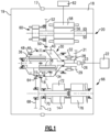
- FIG. 1 shows an integrated drive generator 20. As shown, housing portions 18 and 19 surround the integrated drive generator and a seal plate 17 sits between the housing portions 18 and 19.
- a gas turbine engine 22 may drive an input shaft 23 which selectively drives a disconnect assembly 26.
- the disconnect assembly 26 in turn, drives a carrier shaft 28, which drives a carrier in a gear differential 30.
- Gears 38 have a gear interface 42 with a first ring gear portion 40.
- Gears 36 have a gear interface 48 with a second ring gear portion 46.
- Ring gear portion 40 has a gear interface 50 with a main generator 51 having a drive gear 52.
- drive gear 52 When drive gear 52 is driven to rotate, it rotates a rotor 56 associated with a stator 58 of the main generator as well as an exciter rotor 60. Electric power is generated for a use 62, as known.
- the frequency of the generated electric power be at a desired frequency.
- a gear 15 that is part of the carrier has a gear interface 16 with a gear 13 driving a shaft 14 also within the speed trimmer.
- the speed trimmer 66 includes a variable unit 72 and a fixed unit 76.
- the units 72 and 76 may each be provided with a plurality of pistons and a swash plate arrangement. If the input speed of the gear 13 is too high, the speed of the gear 52 will also be too high, and hence, the speed trimmer 66 acts to lower the speed of the trim gear 46 which will drop the speed of gear 52. On the other hand, if the input speed is too low, the speed trimmer will increase the trim gear speed and he speed seen by gear 52 will increase.
- variable unit 72 receives an input through gear 13 that is proportional to the speed of the input shaft 23.
- the variable unit 72 also receives a control input from a control monitoring the speed of the generator rotor 56.
- the position of the swash plate in the variable unit 72 is changed to in turn change the speed and direction of the fixed unit 76.
- the fixed unit 76 can change the speed, and direction of rotation of the shaft 70, and this then provides control back through the trim ring gear 46 to change the speed reaching the generator.
- the speed trimmer 66 results in the frequency generated by the generator being closer to constant, and at the desired frequency.
- a permanent magnet generator 32 rotates with the ring gear 40.
- An accessory drive shaft 29 rotates with the carrier shaft 28 and drives a plurality of accessory gears 31.
- the operation of the integrated drive generator 20 is generally as known in the art.
- the input drive shaft 23, as described below, is unique. A worker of ordinary skill would recognize that the desired frequency and speed at use 62 would dictate a number of design functions.
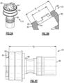
- Figure 2A shows an input drive shaft 23 having a body 80, with clutch teeth 82 circumferentially spaced about an inner bore 84. As shown, there are four clutch teeth 82 extending from a nominal face 83 of body 80.
- Figure 2B shows details of a clutch face on the body 80.
- the inner bore 84 defines a first diameter d 1 .
- the gear teeth 82 extend forwardly of a nominal face 83 and have a radially outer peripheral surface 86.
- a diameter d 2 to the outer surface 86 is also illustrated.
- Figure 2C discloses a distance d 3 between nominal face 83 and an opposed end 90 of the body 80.
- d 3 was 8.46 centimeters (3.330 inches).
- a ratio of d 1 to d 2 was between 1.50 and 1.65.
- a ratio of d 1 to d 3 was between 0.30 and 0.40.
- a ratio of d 2 to d 3 was between 0.50 and 0.60.
- a method of replacing an input drive shaft for an integrated drive generator comprises the steps of a) removing an existing input drive shaft from an integrated drive generator having the existing input shaft, a gear differential including a carrier shaft to be connected to the input drive shaft, and a ring gear connected to a generator; b) replacing the existing input drive shaft with a replacement input drive shaft; and c) the replacement input drive shaft has a body extending from an end to a clutch face, and the clutch face including four gear teeth extending away from a nominal face of the body, the clutch face defining an inner bore of a first diameter, and the clutch face having an outer peripheral surface defining a second diameter and a ratio of the first diameter to the second diameter in accordance with claim 2.
Landscapes
- Engineering & Computer Science (AREA)
- General Engineering & Computer Science (AREA)
- Mechanical Engineering (AREA)
- Chemical & Material Sciences (AREA)
- Combustion & Propulsion (AREA)
- Ocean & Marine Engineering (AREA)
- Retarders (AREA)
- Connection Of Motors, Electrical Generators, Mechanical Devices, And The Like (AREA)
- Structure Of Transmissions (AREA)
Description
- This application relates to an integrated drive generator.
- Integrated drive generators are known and often utilized in aircraft. As known, a gas turbine engine on the aircraft provides a drive input into a generator input shaft. The generator typically includes a disconnect shaft that can transmit the input into a gear differential. The gear differential selectively drives a main generator to provide electric power for various uses on the aircraft.
- It is desirable that the generated power be of a desired constant frequency. However, the speed from the input shaft will vary during operation of the gas turbine engine. This would result in variable frequency.
- Integrated drive generators are provided with speed trimming hydraulic units. Gears associated with the differential and, in particular, a ring gear portion, provide rotation from the differential back into the trimming unit. A carrier also rotates another portion of the trimming unit. The trimming unit is operable to result in the output speed of the differential being effectively constant, such that electric power of a desirable frequency is generated.
- The generator is mounted between two housing portions and a seal plate is mounted between the two housing portions.
- In addition, various accessory systems, such as various pumps, are driven by the carrier of the differential through an accessory drive gear.
- The generator input drive shaft raises design challenges.
- Drive shafts are taught in
US 2016/305491 (which forms the basis for the preamble of the claims),US 2010/156113 andEP 2098741 . - An integrated drive generator is provided as defined by claim 1.
- In addition, a method of replacing an input drive shaft in an integrated drive generator is provided as defined in claim 2.
- These and other features may be best understood from the following drawings and specification.
-
-
Figure 1 schematically shows an integrated drive generator. -
Figure 2A shows an input drive shaft. -
Figure 2B shows details of the clutch face. -
Figure 2C shows details of the input drive shaft. -
Figure 1 shows anintegrated drive generator 20. As shown,housing portions seal plate 17 sits between thehousing portions - A
gas turbine engine 22 may drive aninput shaft 23 which selectively drives adisconnect assembly 26. Thedisconnect assembly 26, in turn, drives acarrier shaft 28, which drives a carrier in agear differential 30. - As the
carrier shaft 28 rotates, planet gears 36 and 38 are caused to rotate.Gears 38 have agear interface 42 with a firstring gear portion 40.Gears 36 have agear interface 48 with a secondring gear portion 46. -
Ring gear portion 40 has agear interface 50 with a main generator 51 having adrive gear 52. Whendrive gear 52 is driven to rotate, it rotates arotor 56 associated with astator 58 of the main generator as well as anexciter rotor 60. Electric power is generated for ause 62, as known. - It is desirable that the frequency of the generated electric power be at a desired frequency. This requires the input speed to gear 52 to be relatively constant and at the desired speed. As such, the speed of the
input shaft 23 is added to the speed of thespeed trimmer 66 to result in a constant input speed to gear 52. - A
gear 15 that is part of the carrier has agear interface 16 with agear 13 driving ashaft 14 also within the speed trimmer. - As known, the
speed trimmer 66 includes avariable unit 72 and a fixedunit 76. Theunits gear 13 is too high, the speed of thegear 52 will also be too high, and hence, thespeed trimmer 66 acts to lower the speed of thetrim gear 46 which will drop the speed ofgear 52. On the other hand, if the input speed is too low, the speed trimmer will increase the trim gear speed and he speed seen bygear 52 will increase. - In essence, the
variable unit 72 receives an input throughgear 13 that is proportional to the speed of theinput shaft 23. Thevariable unit 72 also receives a control input from a control monitoring the speed of thegenerator rotor 56. The position of the swash plate in thevariable unit 72 is changed to in turn change the speed and direction of the fixedunit 76. The fixedunit 76 can change the speed, and direction of rotation of theshaft 70, and this then provides control back through thetrim ring gear 46 to change the speed reaching the generator. In this manner, thespeed trimmer 66 results in the frequency generated by the generator being closer to constant, and at the desired frequency. - A
permanent magnet generator 32 rotates with thering gear 40. - An
accessory drive shaft 29 rotates with thecarrier shaft 28 and drives a plurality of accessory gears 31. - The operation of the
integrated drive generator 20 is generally as known in the art. Theinput drive shaft 23, as described below, is unique. A worker of ordinary skill would recognize that the desired frequency and speed atuse 62 would dictate a number of design functions. -
Figure 2A shows aninput drive shaft 23 having abody 80, withclutch teeth 82 circumferentially spaced about aninner bore 84. As shown, there are fourclutch teeth 82 extending from anominal face 83 ofbody 80. -
Figure 2B shows details of a clutch face on thebody 80. As shown, theinner bore 84 defines a first diameter d1. Thegear teeth 82 extend forwardly of anominal face 83 and have a radially outerperipheral surface 86. A diameter d2 to theouter surface 86 is also illustrated. - di was 2.97 centimeters (1.170 inches) and d2 was 4.699 centimeters (1.845 inches). These and all dimensions in this application carry a manufacturing tolerance of =/- .025 centimeters (.010 inch).
-
Figure 2C discloses a distance d3 betweennominal face 83 and anopposed end 90 of thebody 80. In one embodiment, d3 was 8.46 centimeters (3.330 inches). - In embodiments, a ratio of d1 to d2 was between 1.50 and 1.65. A ratio of d1 to d3 was between 0.30 and 0.40. A ratio of d2 to d3 was between 0.50 and 0.60.
- A method of replacing an input drive shaft for an integrated drive generator comprises the steps of a) removing an existing input drive shaft from an integrated drive generator having the existing input shaft, a gear differential including a carrier shaft to be connected to the input drive shaft, and a ring gear connected to a generator; b) replacing the existing input drive shaft with a replacement input drive shaft; and c) the replacement input drive shaft has a body extending from an end to a clutch face, and the clutch face including four gear teeth extending away from a nominal face of the body, the clutch face defining an inner bore of a first diameter, and the clutch face having an outer peripheral surface defining a second diameter and a ratio of the first diameter to the second diameter in accordance with claim 2.
- Although an embodiment of this invention has been disclosed, a worker of ordinary skill in this art would recognize that certain modifications would come within the scope of the claims.
Claims (2)
- An integrated drive generator comprising:
an input drive shaft (23), a gear differential (30) including a carrier shaft to be driven by said input drive shaft, and including a ring gear (40,46) driving a generator; the input drive shaft comprising:a body (80) extending from an end (90) to a clutch face, and said clutch face including four clutch teeth (82) extending away from a nominal surface (83) of said body, said clutch face defining an inner bore (84) of a first diameter (d1), and said clutch face having an outer peripheral surface (86) defining a second diameter (d2); andcharacterized in that said first diameter is 2.97 cm (1.170 inches) +/-0.025 cm and said second diameter is 4.699 cm (1.845 inches) +/- 0.025 cm, andwherein said nominal surface is spaced from said end by a distance of 8.46 cm (3.330 inches) +/-0.025 cm. - A method of replacing an input drive shaft of an integrated drive generator comprising the steps of:a) removing an existing input drive shaft from an integrated drive generator having said existing input shaft, a gear differential including a carrier shaft to be connected to said input drive shaft, and a ring gear connected to a generator;b) replacing said existing input drive shaft with a replacement input drive shaft; andc) the replacement input drive shaft comprising:a body (80) extending from an end (90) to a clutch face, and said clutch face including four clutch teeth (82) extending away from a nominal surface (83) of said body, said clutch face defining an inner bore (84) of a first diameter (d1), and said clutch face having an outer peripheral surface (86) defining a second diameter (d2);and characterized in that said first diameter is 2.97 cm (1.170 inches) +/-0.025 cm and said second diameter is 4.699 cm (1.845 inches) +/- 0.025 cm;wherein said nominal surface is spaced from said end by a distance of 8.46 cm (3.330 inches) +/-0.025 cm.
Applications Claiming Priority (1)
| Application Number | Priority Date | Filing Date | Title |
|---|---|---|---|
| US15/862,294 US10634063B2 (en) | 2018-01-04 | 2018-01-04 | Input shaft for use in integrated drive generator |
Publications (2)
| Publication Number | Publication Date |
|---|---|
| EP3508746A1 EP3508746A1 (en) | 2019-07-10 |
| EP3508746B1 true EP3508746B1 (en) | 2024-07-31 |
Family
ID=65011813
Family Applications (1)
| Application Number | Title | Priority Date | Filing Date |
|---|---|---|---|
| EP18248193.7A Active EP3508746B1 (en) | 2018-01-04 | 2018-12-28 | Input shaft for use in integrated drive gear |
Country Status (2)
| Country | Link |
|---|---|
| US (1) | US10634063B2 (en) |
| EP (1) | EP3508746B1 (en) |
Families Citing this family (2)
| Publication number | Priority date | Publication date | Assignee | Title |
|---|---|---|---|---|
| US10823230B2 (en) * | 2017-10-03 | 2020-11-03 | Hamilton Sundstrand Corporation | Disconnect shaft for integrated drive generator |
| US11152837B2 (en) | 2019-09-06 | 2021-10-19 | Hamilton Sundstrand Corporation | Generator arrangements and methods of generating electric power with generator arrangements |
Family Cites Families (11)
| Publication number | Priority date | Publication date | Assignee | Title |
|---|---|---|---|---|
| US2769437A (en) * | 1954-09-01 | 1956-11-06 | Studebaker Packard Corp | Starter gear mechanism |
| USRE30525E (en) * | 1975-05-19 | 1981-02-24 | Sundstrand Corporation | Extended range hydraulic transmission |
| DE19624774C2 (en) * | 1996-06-21 | 2000-06-08 | Blw Praezisionsschmiede Gmbh | Clutch teeth in a manual transmission |
| JP2000320438A (en) * | 1999-05-12 | 2000-11-21 | Mitsubishi Electric Corp | Starting motor |
| JP3499177B2 (en) * | 1999-11-10 | 2004-02-23 | 三菱電機株式会社 | Starter |
| FR2881380B1 (en) * | 2005-02-01 | 2007-04-20 | Peugeot Citroen Automobiles Sa | DEVICE FOR COUPLING BETWEEN THE ROTOR OF A REVERSIBLE ROTATING ELECTRIC MACHINE AND THE PRIMARY SHAFT OF THE GEARBOX OF A MOTOR VEHICLE THERMAL MOTOR |
| US7946403B2 (en) | 2008-03-04 | 2011-05-24 | Honeywell International Inc. | Mechanical disconnect dual-sided interlocking teeth |
| US8237298B2 (en) | 2008-12-22 | 2012-08-07 | Hamilton Sundstrand Corporation | Generator coupling for use with gas turbine engine |
| US8987956B2 (en) * | 2009-05-06 | 2015-03-24 | Hamilton Sundstrand Corporation | High speed clutch design with jaw tooth profile to reduce separating load |
| US8049386B2 (en) * | 2009-05-08 | 2011-11-01 | Hamilton Sundstrand Corporation | Seal cartridge |
| US9732804B2 (en) | 2015-04-14 | 2017-08-15 | Hamilton Sundstrand Corporation | Disconnect shaft for an integrated drive generator (IDG) |
-
2018
- 2018-01-04 US US15/862,294 patent/US10634063B2/en active Active
- 2018-12-28 EP EP18248193.7A patent/EP3508746B1/en active Active
Also Published As
| Publication number | Publication date |
|---|---|
| US10634063B2 (en) | 2020-04-28 |
| EP3508746A1 (en) | 2019-07-10 |
| US20190203647A1 (en) | 2019-07-04 |
Similar Documents
| Publication | Publication Date | Title |
|---|---|---|
| EP3508746B1 (en) | Input shaft for use in integrated drive gear | |
| EP3486528B1 (en) | Governor and inversion pump drive gear | |
| EP3509199B1 (en) | Main generator stator sleeve for integrated drive generator | |
| EP3514398B1 (en) | Fixed block shaft inner bearing race for integrated drive generator | |
| EP3467331B1 (en) | Disconnect shaft for integrated drive generator | |
| EP3483443B1 (en) | Pump sleeve for integrated drive generator | |
| EP3467350A1 (en) | Trim ring gear for integrated drive generator | |
| EP3511594B1 (en) | Fixed block shaft for integrated drive generator | |
| EP3467349B1 (en) | Accessory drive gear for integrated drive generator | |
| EP3514324B1 (en) | Cam liner for integrated drive generator | |
| EP3486529B1 (en) | Scavenge/charge pump drive gear for integrated drive generator | |
| EP3502514B1 (en) | Output ring gear for integrated drive generator | |
| EP3508758B1 (en) | Generator driven gear for integrated drive generator | |
| EP3508757B1 (en) | Integrated drive generator and related method for replacing a governor drive gear therein | |
| EP3511595B1 (en) | Variable block shaft for integrated drive generator | |
| EP3489532B1 (en) | Wear ring for integrated drive generator | |
| US10826342B2 (en) | Permanent magnet generator rotor for integrated drive generator | |
| EP3514377A1 (en) | Variable wobbler plate for integrated drive generator |
Legal Events
| Date | Code | Title | Description |
|---|---|---|---|
| PUAI | Public reference made under article 153(3) epc to a published international application that has entered the european phase |
Free format text: ORIGINAL CODE: 0009012 |
|
| STAA | Information on the status of an ep patent application or granted ep patent |
Free format text: STATUS: THE APPLICATION HAS BEEN PUBLISHED |
|
| AK | Designated contracting states |
Kind code of ref document: A1 Designated state(s): AL AT BE BG CH CY CZ DE DK EE ES FI FR GB GR HR HU IE IS IT LI LT LU LV MC MK MT NL NO PL PT RO RS SE SI SK SM TR |
|
| AX | Request for extension of the european patent |
Extension state: BA ME |
|
| STAA | Information on the status of an ep patent application or granted ep patent |
Free format text: STATUS: REQUEST FOR EXAMINATION WAS MADE |
|
| 17P | Request for examination filed |
Effective date: 20191213 |
|
| RBV | Designated contracting states (corrected) |
Designated state(s): AL AT BE BG CH CY CZ DE DK EE ES FI FR GB GR HR HU IE IS IT LI LT LU LV MC MK MT NL NO PL PT RO RS SE SI SK SM TR |
|
| STAA | Information on the status of an ep patent application or granted ep patent |
Free format text: STATUS: EXAMINATION IS IN PROGRESS |
|
| 17Q | First examination report despatched |
Effective date: 20201013 |
|
| GRAP | Despatch of communication of intention to grant a patent |
Free format text: ORIGINAL CODE: EPIDOSNIGR1 |
|
| STAA | Information on the status of an ep patent application or granted ep patent |
Free format text: STATUS: GRANT OF PATENT IS INTENDED |
|
| RIC1 | Information provided on ipc code assigned before grant |
Ipc: F16D 11/14 20060101AFI20240214BHEP |
|
| INTG | Intention to grant announced |
Effective date: 20240301 |
|
| GRAS | Grant fee paid |
Free format text: ORIGINAL CODE: EPIDOSNIGR3 |
|
| GRAA | (expected) grant |
Free format text: ORIGINAL CODE: 0009210 |
|
| STAA | Information on the status of an ep patent application or granted ep patent |
Free format text: STATUS: THE PATENT HAS BEEN GRANTED |
|
| AK | Designated contracting states |
Kind code of ref document: B1 Designated state(s): AL AT BE BG CH CY CZ DE DK EE ES FI FR GB GR HR HU IE IS IT LI LT LU LV MC MK MT NL NO PL PT RO RS SE SI SK SM TR |
|
| REG | Reference to a national code |
Ref country code: CH Ref legal event code: EP Ref country code: GB Ref legal event code: FG4D |
|
| REG | Reference to a national code |
Ref country code: DE Ref legal event code: R096 Ref document number: 602018072398 Country of ref document: DE |
|
| REG | Reference to a national code |
Ref country code: IE Ref legal event code: FG4D |
|
| REG | Reference to a national code |
Ref country code: LT Ref legal event code: MG9D |
|
| REG | Reference to a national code |
Ref country code: NL Ref legal event code: MP Effective date: 20240731 |
|
| PG25 | Lapsed in a contracting state [announced via postgrant information from national office to epo] |
Ref country code: PT Free format text: LAPSE BECAUSE OF FAILURE TO SUBMIT A TRANSLATION OF THE DESCRIPTION OR TO PAY THE FEE WITHIN THE PRESCRIBED TIME-LIMIT Effective date: 20241202 |
|
| REG | Reference to a national code |
Ref country code: AT Ref legal event code: MK05 Ref document number: 1708708 Country of ref document: AT Kind code of ref document: T Effective date: 20240731 |
|
| PG25 | Lapsed in a contracting state [announced via postgrant information from national office to epo] |
Ref country code: PT Free format text: LAPSE BECAUSE OF FAILURE TO SUBMIT A TRANSLATION OF THE DESCRIPTION OR TO PAY THE FEE WITHIN THE PRESCRIBED TIME-LIMIT Effective date: 20241202 |
|
| PG25 | Lapsed in a contracting state [announced via postgrant information from national office to epo] |
Ref country code: NO Free format text: LAPSE BECAUSE OF FAILURE TO SUBMIT A TRANSLATION OF THE DESCRIPTION OR TO PAY THE FEE WITHIN THE PRESCRIBED TIME-LIMIT Effective date: 20241031 |
|
| PG25 | Lapsed in a contracting state [announced via postgrant information from national office to epo] |
Ref country code: FI Free format text: LAPSE BECAUSE OF FAILURE TO SUBMIT A TRANSLATION OF THE DESCRIPTION OR TO PAY THE FEE WITHIN THE PRESCRIBED TIME-LIMIT Effective date: 20240731 Ref country code: NL Free format text: LAPSE BECAUSE OF FAILURE TO SUBMIT A TRANSLATION OF THE DESCRIPTION OR TO PAY THE FEE WITHIN THE PRESCRIBED TIME-LIMIT Effective date: 20240731 Ref country code: PL Free format text: LAPSE BECAUSE OF FAILURE TO SUBMIT A TRANSLATION OF THE DESCRIPTION OR TO PAY THE FEE WITHIN THE PRESCRIBED TIME-LIMIT Effective date: 20240731 Ref country code: GR Free format text: LAPSE BECAUSE OF FAILURE TO SUBMIT A TRANSLATION OF THE DESCRIPTION OR TO PAY THE FEE WITHIN THE PRESCRIBED TIME-LIMIT Effective date: 20241101 |
|
| PG25 | Lapsed in a contracting state [announced via postgrant information from national office to epo] |
Ref country code: BG Free format text: LAPSE BECAUSE OF FAILURE TO SUBMIT A TRANSLATION OF THE DESCRIPTION OR TO PAY THE FEE WITHIN THE PRESCRIBED TIME-LIMIT Effective date: 20240731 |
|
| PG25 | Lapsed in a contracting state [announced via postgrant information from national office to epo] |
Ref country code: LV Free format text: LAPSE BECAUSE OF FAILURE TO SUBMIT A TRANSLATION OF THE DESCRIPTION OR TO PAY THE FEE WITHIN THE PRESCRIBED TIME-LIMIT Effective date: 20240731 |
|
| PG25 | Lapsed in a contracting state [announced via postgrant information from national office to epo] |
Ref country code: AT Free format text: LAPSE BECAUSE OF FAILURE TO SUBMIT A TRANSLATION OF THE DESCRIPTION OR TO PAY THE FEE WITHIN THE PRESCRIBED TIME-LIMIT Effective date: 20240731 Ref country code: IS Free format text: LAPSE BECAUSE OF FAILURE TO SUBMIT A TRANSLATION OF THE DESCRIPTION OR TO PAY THE FEE WITHIN THE PRESCRIBED TIME-LIMIT Effective date: 20241130 |
|
| PG25 | Lapsed in a contracting state [announced via postgrant information from national office to epo] |
Ref country code: HR Free format text: LAPSE BECAUSE OF FAILURE TO SUBMIT A TRANSLATION OF THE DESCRIPTION OR TO PAY THE FEE WITHIN THE PRESCRIBED TIME-LIMIT Effective date: 20240731 |
|
| PG25 | Lapsed in a contracting state [announced via postgrant information from national office to epo] |
Ref country code: RS Free format text: LAPSE BECAUSE OF FAILURE TO SUBMIT A TRANSLATION OF THE DESCRIPTION OR TO PAY THE FEE WITHIN THE PRESCRIBED TIME-LIMIT Effective date: 20241031 Ref country code: ES Free format text: LAPSE BECAUSE OF FAILURE TO SUBMIT A TRANSLATION OF THE DESCRIPTION OR TO PAY THE FEE WITHIN THE PRESCRIBED TIME-LIMIT Effective date: 20240731 |
|
| PG25 | Lapsed in a contracting state [announced via postgrant information from national office to epo] |
Ref country code: RS Free format text: LAPSE BECAUSE OF FAILURE TO SUBMIT A TRANSLATION OF THE DESCRIPTION OR TO PAY THE FEE WITHIN THE PRESCRIBED TIME-LIMIT Effective date: 20241031 Ref country code: PL Free format text: LAPSE BECAUSE OF FAILURE TO SUBMIT A TRANSLATION OF THE DESCRIPTION OR TO PAY THE FEE WITHIN THE PRESCRIBED TIME-LIMIT Effective date: 20240731 Ref country code: NO Free format text: LAPSE BECAUSE OF FAILURE TO SUBMIT A TRANSLATION OF THE DESCRIPTION OR TO PAY THE FEE WITHIN THE PRESCRIBED TIME-LIMIT Effective date: 20241031 Ref country code: NL Free format text: LAPSE BECAUSE OF FAILURE TO SUBMIT A TRANSLATION OF THE DESCRIPTION OR TO PAY THE FEE WITHIN THE PRESCRIBED TIME-LIMIT Effective date: 20240731 Ref country code: LV Free format text: LAPSE BECAUSE OF FAILURE TO SUBMIT A TRANSLATION OF THE DESCRIPTION OR TO PAY THE FEE WITHIN THE PRESCRIBED TIME-LIMIT Effective date: 20240731 Ref country code: IS Free format text: LAPSE BECAUSE OF FAILURE TO SUBMIT A TRANSLATION OF THE DESCRIPTION OR TO PAY THE FEE WITHIN THE PRESCRIBED TIME-LIMIT Effective date: 20241130 Ref country code: HR Free format text: LAPSE BECAUSE OF FAILURE TO SUBMIT A TRANSLATION OF THE DESCRIPTION OR TO PAY THE FEE WITHIN THE PRESCRIBED TIME-LIMIT Effective date: 20240731 Ref country code: GR Free format text: LAPSE BECAUSE OF FAILURE TO SUBMIT A TRANSLATION OF THE DESCRIPTION OR TO PAY THE FEE WITHIN THE PRESCRIBED TIME-LIMIT Effective date: 20241101 Ref country code: FI Free format text: LAPSE BECAUSE OF FAILURE TO SUBMIT A TRANSLATION OF THE DESCRIPTION OR TO PAY THE FEE WITHIN THE PRESCRIBED TIME-LIMIT Effective date: 20240731 Ref country code: ES Free format text: LAPSE BECAUSE OF FAILURE TO SUBMIT A TRANSLATION OF THE DESCRIPTION OR TO PAY THE FEE WITHIN THE PRESCRIBED TIME-LIMIT Effective date: 20240731 Ref country code: BG Free format text: LAPSE BECAUSE OF FAILURE TO SUBMIT A TRANSLATION OF THE DESCRIPTION OR TO PAY THE FEE WITHIN THE PRESCRIBED TIME-LIMIT Effective date: 20240731 Ref country code: AT Free format text: LAPSE BECAUSE OF FAILURE TO SUBMIT A TRANSLATION OF THE DESCRIPTION OR TO PAY THE FEE WITHIN THE PRESCRIBED TIME-LIMIT Effective date: 20240731 |
|
| PG25 | Lapsed in a contracting state [announced via postgrant information from national office to epo] |
Ref country code: SM Free format text: LAPSE BECAUSE OF FAILURE TO SUBMIT A TRANSLATION OF THE DESCRIPTION OR TO PAY THE FEE WITHIN THE PRESCRIBED TIME-LIMIT Effective date: 20240731 Ref country code: DK Free format text: LAPSE BECAUSE OF FAILURE TO SUBMIT A TRANSLATION OF THE DESCRIPTION OR TO PAY THE FEE WITHIN THE PRESCRIBED TIME-LIMIT Effective date: 20240731 Ref country code: RO Free format text: LAPSE BECAUSE OF FAILURE TO SUBMIT A TRANSLATION OF THE DESCRIPTION OR TO PAY THE FEE WITHIN THE PRESCRIBED TIME-LIMIT Effective date: 20240731 |
|
| PG25 | Lapsed in a contracting state [announced via postgrant information from national office to epo] |
Ref country code: EE Free format text: LAPSE BECAUSE OF FAILURE TO SUBMIT A TRANSLATION OF THE DESCRIPTION OR TO PAY THE FEE WITHIN THE PRESCRIBED TIME-LIMIT Effective date: 20240731 |
|
| PG25 | Lapsed in a contracting state [announced via postgrant information from national office to epo] |
Ref country code: CZ Free format text: LAPSE BECAUSE OF FAILURE TO SUBMIT A TRANSLATION OF THE DESCRIPTION OR TO PAY THE FEE WITHIN THE PRESCRIBED TIME-LIMIT Effective date: 20240731 |
|
| PG25 | Lapsed in a contracting state [announced via postgrant information from national office to epo] |
Ref country code: SK Free format text: LAPSE BECAUSE OF FAILURE TO SUBMIT A TRANSLATION OF THE DESCRIPTION OR TO PAY THE FEE WITHIN THE PRESCRIBED TIME-LIMIT Effective date: 20240731 Ref country code: IT Free format text: LAPSE BECAUSE OF FAILURE TO SUBMIT A TRANSLATION OF THE DESCRIPTION OR TO PAY THE FEE WITHIN THE PRESCRIBED TIME-LIMIT Effective date: 20240731 |
|
| REG | Reference to a national code |
Ref country code: DE Ref legal event code: R097 Ref document number: 602018072398 Country of ref document: DE |
|
| PLBE | No opposition filed within time limit |
Free format text: ORIGINAL CODE: 0009261 |
|
| STAA | Information on the status of an ep patent application or granted ep patent |
Free format text: STATUS: NO OPPOSITION FILED WITHIN TIME LIMIT |
|
| PG25 | Lapsed in a contracting state [announced via postgrant information from national office to epo] |
Ref country code: MC Free format text: LAPSE BECAUSE OF FAILURE TO SUBMIT A TRANSLATION OF THE DESCRIPTION OR TO PAY THE FEE WITHIN THE PRESCRIBED TIME-LIMIT Effective date: 20240731 |
|
| 26N | No opposition filed |
Effective date: 20250501 |
|
| REG | Reference to a national code |
Ref country code: CH Ref legal event code: PL |
|
| PG25 | Lapsed in a contracting state [announced via postgrant information from national office to epo] |
Ref country code: LU Free format text: LAPSE BECAUSE OF NON-PAYMENT OF DUE FEES Effective date: 20241228 |
|
| PG25 | Lapsed in a contracting state [announced via postgrant information from national office to epo] |
Ref country code: SE Free format text: LAPSE BECAUSE OF FAILURE TO SUBMIT A TRANSLATION OF THE DESCRIPTION OR TO PAY THE FEE WITHIN THE PRESCRIBED TIME-LIMIT Effective date: 20240731 |
|
| REG | Reference to a national code |
Ref country code: BE Ref legal event code: MM Effective date: 20241231 |
|
| PG25 | Lapsed in a contracting state [announced via postgrant information from national office to epo] |
Ref country code: BE Free format text: LAPSE BECAUSE OF NON-PAYMENT OF DUE FEES Effective date: 20241231 |
|
| PG25 | Lapsed in a contracting state [announced via postgrant information from national office to epo] |
Ref country code: CH Free format text: LAPSE BECAUSE OF NON-PAYMENT OF DUE FEES Effective date: 20241231 |
|
| PG25 | Lapsed in a contracting state [announced via postgrant information from national office to epo] |
Ref country code: IE Free format text: LAPSE BECAUSE OF NON-PAYMENT OF DUE FEES Effective date: 20241228 |
|
| PGFP | Annual fee paid to national office [announced via postgrant information from national office to epo] |
Ref country code: DE Payment date: 20251126 Year of fee payment: 8 |
|
| PGFP | Annual fee paid to national office [announced via postgrant information from national office to epo] |
Ref country code: GB Payment date: 20251120 Year of fee payment: 8 |
|
| PGFP | Annual fee paid to national office [announced via postgrant information from national office to epo] |
Ref country code: FR Payment date: 20251119 Year of fee payment: 8 |