EP3508744A1 - Securing element for a bearing device, bearing device and windscreen wiper motor - Google Patents
Securing element for a bearing device, bearing device and windscreen wiper motor Download PDFInfo
- Publication number
- EP3508744A1 EP3508744A1 EP18214927.8A EP18214927A EP3508744A1 EP 3508744 A1 EP3508744 A1 EP 3508744A1 EP 18214927 A EP18214927 A EP 18214927A EP 3508744 A1 EP3508744 A1 EP 3508744A1
- Authority
- EP
- European Patent Office
- Prior art keywords
- securing element
- bearing
- receptacle
- bulge
- side legs
- Prior art date
- Legal status (The legal status is an assumption and is not a legal conclusion. Google has not performed a legal analysis and makes no representation as to the accuracy of the status listed.)
- Granted
Links
Images
Classifications
-
- F—MECHANICAL ENGINEERING; LIGHTING; HEATING; WEAPONS; BLASTING
- F16—ENGINEERING ELEMENTS AND UNITS; GENERAL MEASURES FOR PRODUCING AND MAINTAINING EFFECTIVE FUNCTIONING OF MACHINES OR INSTALLATIONS; THERMAL INSULATION IN GENERAL
- F16B—DEVICES FOR FASTENING OR SECURING CONSTRUCTIONAL ELEMENTS OR MACHINE PARTS TOGETHER, e.g. NAILS, BOLTS, CIRCLIPS, CLAMPS, CLIPS OR WEDGES; JOINTS OR JOINTING
- F16B43/00—Washers or equivalent devices; Other devices for supporting bolt-heads or nuts
- F16B43/005—Washers or equivalent devices; Other devices for supporting bolt-heads or nuts engaging the bolt laterally to allow a quick mounting or dismounting of the washer, i.e. without the need to engage over the end of the bolt
-
- F—MECHANICAL ENGINEERING; LIGHTING; HEATING; WEAPONS; BLASTING
- F16—ENGINEERING ELEMENTS AND UNITS; GENERAL MEASURES FOR PRODUCING AND MAINTAINING EFFECTIVE FUNCTIONING OF MACHINES OR INSTALLATIONS; THERMAL INSULATION IN GENERAL
- F16C—SHAFTS; FLEXIBLE SHAFTS; ELEMENTS OR CRANKSHAFT MECHANISMS; ROTARY BODIES OTHER THAN GEARING ELEMENTS; BEARINGS
- F16C35/00—Rigid support of bearing units; Housings, e.g. caps, covers
- F16C35/04—Rigid support of bearing units; Housings, e.g. caps, covers in the case of ball or roller bearings
- F16C35/06—Mounting or dismounting of ball or roller bearings; Fixing them onto shaft or in housing
-
- F—MECHANICAL ENGINEERING; LIGHTING; HEATING; WEAPONS; BLASTING
- F16—ENGINEERING ELEMENTS AND UNITS; GENERAL MEASURES FOR PRODUCING AND MAINTAINING EFFECTIVE FUNCTIONING OF MACHINES OR INSTALLATIONS; THERMAL INSULATION IN GENERAL
- F16C—SHAFTS; FLEXIBLE SHAFTS; ELEMENTS OR CRANKSHAFT MECHANISMS; ROTARY BODIES OTHER THAN GEARING ELEMENTS; BEARINGS
- F16C19/00—Bearings with rolling contact, for exclusively rotary movement
- F16C19/02—Bearings with rolling contact, for exclusively rotary movement with bearing balls essentially of the same size in one or more circular rows
- F16C19/04—Bearings with rolling contact, for exclusively rotary movement with bearing balls essentially of the same size in one or more circular rows for radial load mainly
- F16C19/06—Bearings with rolling contact, for exclusively rotary movement with bearing balls essentially of the same size in one or more circular rows for radial load mainly with a single row or balls
-
- F—MECHANICAL ENGINEERING; LIGHTING; HEATING; WEAPONS; BLASTING
- F16—ENGINEERING ELEMENTS AND UNITS; GENERAL MEASURES FOR PRODUCING AND MAINTAINING EFFECTIVE FUNCTIONING OF MACHINES OR INSTALLATIONS; THERMAL INSULATION IN GENERAL
- F16C—SHAFTS; FLEXIBLE SHAFTS; ELEMENTS OR CRANKSHAFT MECHANISMS; ROTARY BODIES OTHER THAN GEARING ELEMENTS; BEARINGS
- F16C23/00—Bearings for exclusively rotary movement adjustable for aligning or positioning
- F16C23/06—Ball or roller bearings
-
- F—MECHANICAL ENGINEERING; LIGHTING; HEATING; WEAPONS; BLASTING
- F16—ENGINEERING ELEMENTS AND UNITS; GENERAL MEASURES FOR PRODUCING AND MAINTAINING EFFECTIVE FUNCTIONING OF MACHINES OR INSTALLATIONS; THERMAL INSULATION IN GENERAL
- F16C—SHAFTS; FLEXIBLE SHAFTS; ELEMENTS OR CRANKSHAFT MECHANISMS; ROTARY BODIES OTHER THAN GEARING ELEMENTS; BEARINGS
- F16C25/00—Bearings for exclusively rotary movement adjustable for wear or play
- F16C25/06—Ball or roller bearings
-
- F—MECHANICAL ENGINEERING; LIGHTING; HEATING; WEAPONS; BLASTING
- F16—ENGINEERING ELEMENTS AND UNITS; GENERAL MEASURES FOR PRODUCING AND MAINTAINING EFFECTIVE FUNCTIONING OF MACHINES OR INSTALLATIONS; THERMAL INSULATION IN GENERAL
- F16C—SHAFTS; FLEXIBLE SHAFTS; ELEMENTS OR CRANKSHAFT MECHANISMS; ROTARY BODIES OTHER THAN GEARING ELEMENTS; BEARINGS
- F16C27/00—Elastic or yielding bearings or bearing supports, for exclusively rotary movement
- F16C27/04—Ball or roller bearings, e.g. with resilient rolling bodies
-
- F—MECHANICAL ENGINEERING; LIGHTING; HEATING; WEAPONS; BLASTING
- F16—ENGINEERING ELEMENTS AND UNITS; GENERAL MEASURES FOR PRODUCING AND MAINTAINING EFFECTIVE FUNCTIONING OF MACHINES OR INSTALLATIONS; THERMAL INSULATION IN GENERAL
- F16C—SHAFTS; FLEXIBLE SHAFTS; ELEMENTS OR CRANKSHAFT MECHANISMS; ROTARY BODIES OTHER THAN GEARING ELEMENTS; BEARINGS
- F16C35/00—Rigid support of bearing units; Housings, e.g. caps, covers
- F16C35/04—Rigid support of bearing units; Housings, e.g. caps, covers in the case of ball or roller bearings
-
- F—MECHANICAL ENGINEERING; LIGHTING; HEATING; WEAPONS; BLASTING
- F16—ENGINEERING ELEMENTS AND UNITS; GENERAL MEASURES FOR PRODUCING AND MAINTAINING EFFECTIVE FUNCTIONING OF MACHINES OR INSTALLATIONS; THERMAL INSULATION IN GENERAL
- F16C—SHAFTS; FLEXIBLE SHAFTS; ELEMENTS OR CRANKSHAFT MECHANISMS; ROTARY BODIES OTHER THAN GEARING ELEMENTS; BEARINGS
- F16C35/00—Rigid support of bearing units; Housings, e.g. caps, covers
- F16C35/04—Rigid support of bearing units; Housings, e.g. caps, covers in the case of ball or roller bearings
- F16C35/06—Mounting or dismounting of ball or roller bearings; Fixing them onto shaft or in housing
- F16C35/063—Fixing them on the shaft
-
- F—MECHANICAL ENGINEERING; LIGHTING; HEATING; WEAPONS; BLASTING
- F16—ENGINEERING ELEMENTS AND UNITS; GENERAL MEASURES FOR PRODUCING AND MAINTAINING EFFECTIVE FUNCTIONING OF MACHINES OR INSTALLATIONS; THERMAL INSULATION IN GENERAL
- F16C—SHAFTS; FLEXIBLE SHAFTS; ELEMENTS OR CRANKSHAFT MECHANISMS; ROTARY BODIES OTHER THAN GEARING ELEMENTS; BEARINGS
- F16C35/00—Rigid support of bearing units; Housings, e.g. caps, covers
- F16C35/04—Rigid support of bearing units; Housings, e.g. caps, covers in the case of ball or roller bearings
- F16C35/06—Mounting or dismounting of ball or roller bearings; Fixing them onto shaft or in housing
- F16C35/067—Fixing them in a housing
-
- F—MECHANICAL ENGINEERING; LIGHTING; HEATING; WEAPONS; BLASTING
- F16—ENGINEERING ELEMENTS AND UNITS; GENERAL MEASURES FOR PRODUCING AND MAINTAINING EFFECTIVE FUNCTIONING OF MACHINES OR INSTALLATIONS; THERMAL INSULATION IN GENERAL
- F16B—DEVICES FOR FASTENING OR SECURING CONSTRUCTIONAL ELEMENTS OR MACHINE PARTS TOGETHER, e.g. NAILS, BOLTS, CIRCLIPS, CLAMPS, CLIPS OR WEDGES; JOINTS OR JOINTING
- F16B21/00—Means for preventing relative axial movement of a pin, spigot, shaft or the like and a member surrounding it; Stud-and-socket releasable fastenings
- F16B21/10—Means for preventing relative axial movement of a pin, spigot, shaft or the like and a member surrounding it; Stud-and-socket releasable fastenings by separate parts
- F16B21/16—Means for preventing relative axial movement of a pin, spigot, shaft or the like and a member surrounding it; Stud-and-socket releasable fastenings by separate parts with grooves or notches in the pin or shaft
- F16B21/18—Means for preventing relative axial movement of a pin, spigot, shaft or the like and a member surrounding it; Stud-and-socket releasable fastenings by separate parts with grooves or notches in the pin or shaft with circlips or like resilient retaining devices, i.e. resilient in the plane of the ring or the like; Details
- F16B21/183—Means for preventing relative axial movement of a pin, spigot, shaft or the like and a member surrounding it; Stud-and-socket releasable fastenings by separate parts with grooves or notches in the pin or shaft with circlips or like resilient retaining devices, i.e. resilient in the plane of the ring or the like; Details internal, i.e. with spreading action
-
- F—MECHANICAL ENGINEERING; LIGHTING; HEATING; WEAPONS; BLASTING
- F16—ENGINEERING ELEMENTS AND UNITS; GENERAL MEASURES FOR PRODUCING AND MAINTAINING EFFECTIVE FUNCTIONING OF MACHINES OR INSTALLATIONS; THERMAL INSULATION IN GENERAL
- F16C—SHAFTS; FLEXIBLE SHAFTS; ELEMENTS OR CRANKSHAFT MECHANISMS; ROTARY BODIES OTHER THAN GEARING ELEMENTS; BEARINGS
- F16C2229/00—Setting preload
-
- F—MECHANICAL ENGINEERING; LIGHTING; HEATING; WEAPONS; BLASTING
- F16—ENGINEERING ELEMENTS AND UNITS; GENERAL MEASURES FOR PRODUCING AND MAINTAINING EFFECTIVE FUNCTIONING OF MACHINES OR INSTALLATIONS; THERMAL INSULATION IN GENERAL
- F16C—SHAFTS; FLEXIBLE SHAFTS; ELEMENTS OR CRANKSHAFT MECHANISMS; ROTARY BODIES OTHER THAN GEARING ELEMENTS; BEARINGS
- F16C2326/00—Articles relating to transporting
- F16C2326/01—Parts of vehicles in general
- F16C2326/09—Windscreen wipers, e.g. pivots therefore
-
- F—MECHANICAL ENGINEERING; LIGHTING; HEATING; WEAPONS; BLASTING
- F16—ENGINEERING ELEMENTS AND UNITS; GENERAL MEASURES FOR PRODUCING AND MAINTAINING EFFECTIVE FUNCTIONING OF MACHINES OR INSTALLATIONS; THERMAL INSULATION IN GENERAL
- F16C—SHAFTS; FLEXIBLE SHAFTS; ELEMENTS OR CRANKSHAFT MECHANISMS; ROTARY BODIES OTHER THAN GEARING ELEMENTS; BEARINGS
- F16C2380/00—Electrical apparatus
- F16C2380/26—Dynamo-electric machines or combinations therewith, e.g. electro-motors and generators
-
- F—MECHANICAL ENGINEERING; LIGHTING; HEATING; WEAPONS; BLASTING
- F16—ENGINEERING ELEMENTS AND UNITS; GENERAL MEASURES FOR PRODUCING AND MAINTAINING EFFECTIVE FUNCTIONING OF MACHINES OR INSTALLATIONS; THERMAL INSULATION IN GENERAL
- F16F—SPRINGS; SHOCK-ABSORBERS; MEANS FOR DAMPING VIBRATION
- F16F1/00—Springs
- F16F1/02—Springs made of steel or other material having low internal friction; Wound, torsion, leaf, cup, ring or the like springs, the material of the spring not being relevant
- F16F1/025—Springs made of steel or other material having low internal friction; Wound, torsion, leaf, cup, ring or the like springs, the material of the spring not being relevant characterised by having a particular shape
Definitions
- the invention relates to a securing element for a bearing device in a housing of a drive device, to a bearing device, and to a windscreen wiper motor having a bearing device.
- a securing element for a bearing device in a housing of a drive device having the features of the preamble of claim 1 is already known from practice.
- the substantially flat securing element which is U-shaped in plan view, is in this case arranged in a receptacle of a housing of the drive device such that one face side of said securing element is arranged so as to be regionally in abutting contact with a bearing which serves for the rotatable mounting of a shaft, whereas the other face side of the securing element is regionally supported against an abutment surface of the receptacle.
- the known securing element serves for fixing the bearing in the receptacle and for compensating component tolerances or preventing axial play between the components.
- the known securing element has elevations which are formed by means of a stamping process and which are arranged in the region of the two side legs and on a face side.
- the elevations, which are of dome-shaped form, make it possible, as the securing element is slid into the receptacle, for the securing element to be received in the receptacle with the abovementioned clamping connection being formed.
- a disadvantage here is that the securing element can be received with clamping action in the receptacle only if the axial gap in the receptacle between the abutment surface and that face surface of the bearing which faces toward the securing element has relatively narrow tolerances. Furthermore, depending on component tolerances, relatively high installation forces are required for the insertion of the securing element in the axial direction.
- the securing element according to the invention for a bearing device in a housing of a drive device having the features of claim 1 has the advantage that it permits a greater range of tolerances with regard to the dimensioning of the receptacle in the housing of the drive device, and, at the same time, the forces required for installing the securing element in the receptacle of the drive device are reduced.
- said securing element can be elastically deformed as it is inserted into the receptacle between the stop surface of the receptacle and that face surface of the bearing which faces toward the securing element, wherein the deformation forces required for this purpose or the installation forces are relatively low.
- the elastic deformation a relatively large tolerance for the size of the receptacle for the securing element in the housing is made possible, because, in the case of an axial gap of decreasing size in the receptacle, the bulge of the securing element is reduced to an ever greater degree during the installation until, in the extreme case, said securing element no longer has a bulge in the installed state.
- the dimension for the size of the receptacle for the securing element is thus determined by the dimension by which the securing element is bulged in the non-installed state.
- the form of such a bulge on the securing element can be produced very easily in terms of production by means of a bending process, such that, by contrast to the prior art, it is for example the case that no stamping steps or no plastic deformation of the material of the securing element (elevations) is necessary.
- the bulge of the securing element in the region of the side legs is particularly preferred in which the at least one axis, perpendicularly to which the securing element is bent, is the direction of the longitudinal extent of the side legs. This is realized against the background that the side legs normally have a greater length in terms of their longitudinal extent than the base leg. Furthermore, in this way, points of abutting contact between the securing element and the bearing and the stop surfaces in the housing are made possible on opposite sides of the shaft.
- the at least one axis about which the securing element is of bulged form to run perpendicular to the direction of the longitudinal extent of the base leg.
- a uniform deformation of the securing element during the insertion into the receptacle of the housing is achieved if the bulge is formed by a radius. Furthermore, by means of such a radius, linearly increasing installation forces during the insertion of the securing element into the receptacle of the bearing device are also achieved, which can thus be monitored and evaluated in a particularly effective manner in terms of process technology.
- the securing element In order that the securing element can be in abutting contact over the greatest possible area in the region of the receptacle, in order to thus reduce the contact pressure and thus the material loading of the housing, which is composed in particular of aluminium, it is advantageous if the securing element has planar portions at peripheral elements outside the bulge.
- the securing element at a first face side and in the region of the two side legs, has in each case one elevation, formed preferably by means of a stamping process, for abutment against the bearing.
- the element is composed of spring steel and to have a thickness of between 0.8 mm and 1.2 mm, preferably of 1.0 mm.
- the invention also encompasses a bearing device in a housing of a drive device, having a receptacle for a bearing for the rotatable mounting of a shaft and having a securing element designed according to the invention in the manner described above, wherein the receptacle forms a stop surface on a side of the securing element situated opposite the bearing, and wherein the receptacle has, between the bearing and the stop surface, an axial gap with a width which corresponds at most to the structural height of the securing element in the region of the bulge and at least to the thickness of the material of the securing element.
- the invention also encompasses a windscreen wiper motor having a bearing device of said type.
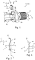
- FIGs 1 and 3 illustrate individual constituent parts of a windscreen wiper motor 100.
- the windscreen wiper motor 100 has a drive device 10, which comprises inter alia an armature 14 with an armature lamination assembly 11 and armature windings (not illustrated).
- the armature lamination assembly 11 is fastened rotationally conjointly to a shaft 12 of the armature 14, wherein the shaft 12 is mounted rotatably about an axis of rotation 13.
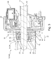
- the mounting of the shaft 12 is performed by means of multiple bearing bodies or bearings 15, which are a constituent part of a bearing device 50, wherein one of the bearings 15 is illustrated in the form of a rolling bearing or ball bearing in Figure 3 .
- the bearing 15 comprises an inner ring 16, which is fastened rotationally conjointly to the outer circumference of the shaft 12, for example by shrink-fitting. Furthermore, the bearing 15 comprises an outer ring 17, which is received, with the formation of an interference fit, in a receptacle 19 of the bearing device 50 of a housing 20, composed preferably of aluminium, of the windscreen wiper motor 100. Bearing bodies 22 are arranged, at uniform angular intervals about the axis of rotation 13, between the inner ring 16 and the outer ring 17.
- one face surface 24 of the bearing 15 bears axially against a step 26 of the receptacle 19. Also visible in Figure 3 is a commutator device 28 of the drive device 10, which commutator device is received in a pot-shaped or cup-shaped housing portion 29.
- a securing element 1 according to the invention of the bearing device 50, which securing element is, in the receptacle 19, correspondingly to the illustration of Figure 3 , supported by means of its two face surfaces 21, 23 axially between the inner ring 16 of the bearing 15 and a stop surface 33, running perpendicular to the direction of the arrow 31 or to the plane of the drawing of Figure 3 , of the receptacle 19.
- the plate-like securing element 1 which can be seen particularly clearly in Figures 1 and 2 is composed of spring steel and preferably has a thickness d of between 0.8 mm and 1.2 mm, preferably of 1.0 mm.
- Said securing element is of U-shaped form in plan view with two side legs 34, 35 and a base leg 36 which connects the two side legs 34, 35 to one another. Formed between the side legs 34, 35 is a cutout 38 which is designed to receive the shaft 12 with play.
- the securing element 1 is introduced into the receptacle 19 of the housing 20 in the direction of the arrow 39 (perpendicular to the axis of rotation 13), wherein said securing element elastically deforms. It is essential here that, correspondingly to the illustration of Figure 2 , the securing element 1 is designed to be regionally bent in a direction running perpendicular to the two axes X, Y running in the plane of the securing element 1 (see Figure 1 ). In the illustration of Figure 2 , the Y axis runs perpendicular to the plane of the drawing of Figure 2 .
- the securing element 1 is designed to be regionally bent in the extent direction or along the two side legs 34, 35, and has, in an approximately central region in relation to the axial extent of the two side legs 34, 35, a bulge 40 which is formed by a radius R.
- the bulge 40 is formed uniformly on both face sides of the securing element 1, that is to say the material thickness of the securing element 1 is at least substantially equal in the region of the two side legs 34, 35.
- the securing element 1 On both sides of the bulge 40, the securing element 1 has portions 41, 42 of planar form, which in the installed state of the securing element 1 in the receptacle 19 preferably bear flat against the abutment surface 33 of the receptacle 19 ( Figure 3 ). Furthermore, the securing element 1, in the region of the base leg 36, has an installation and stiffening portion 45 which is bent through 90 degrees and which serves for example for the handling of the securing element 1 during the insertion into the receptacle 19.
- the securing element 1 is elastically deformed in the region, in particular, of the bulge 40, such that the latter acts with an axial force on the shaft 12 in the direction of the step 26 or of the axis of rotation 13.
- the securing element 1 has a structural height h perpendicular to the plane of the securing element 1 which is at least somewhat greater than the width w of the receptacle 19 between the bearing 15 and the stop surface 33.
- the width w of the receptacle 19 must be at least as large as the thickness d of the securing element 1.
- the securing element 1a illustrated in Figure 4 differs from the securing element 1 in that, on the side facing toward the installation and stiffening portion 45 and in the region of the bulge 40, an elevation 48 is additionally formed on each side leg 34, 35, which elevation is preferably formed by means of a stamping process.
- the elevation 48 serves for punctiform abutment against the inner ring 16 of the bearing 15.
- the securing element 1, 1a thus described may be altered or modified in a variety of ways without departing from the concept of the invention.
Landscapes
- Engineering & Computer Science (AREA)
- General Engineering & Computer Science (AREA)
- Mechanical Engineering (AREA)
- Motor Or Generator Frames (AREA)
- Mounting Of Bearings Or Others (AREA)
- Support Of The Bearing (AREA)
- Rolling Contact Bearings (AREA)
Abstract
Description
- The invention relates to a securing element for a bearing device in a housing of a drive device, to a bearing device, and to a windscreen wiper motor having a bearing device.
- A securing element for a bearing device in a housing of a drive device having the features of the preamble of claim 1 is already known from practice. The substantially flat securing element, which is U-shaped in plan view, is in this case arranged in a receptacle of a housing of the drive device such that one face side of said securing element is arranged so as to be regionally in abutting contact with a bearing which serves for the rotatable mounting of a shaft, whereas the other face side of the securing element is regionally supported against an abutment surface of the receptacle. The known securing element serves for fixing the bearing in the receptacle and for compensating component tolerances or preventing axial play between the components. For this purpose, it is necessary for the securing element to be braced, or arranged with a clamping fit, between the abutment surface of the receptacle and the face side of the bearing. To ensure this, the known securing element has elevations which are formed by means of a stamping process and which are arranged in the region of the two side legs and on a face side. The elevations, which are of dome-shaped form, make it possible, as the securing element is slid into the receptacle, for the securing element to be received in the receptacle with the abovementioned clamping connection being formed. A disadvantage here is that the securing element can be received with clamping action in the receptacle only if the axial gap in the receptacle between the abutment surface and that face surface of the bearing which faces toward the securing element has relatively narrow tolerances. Furthermore, depending on component tolerances, relatively high installation forces are required for the insertion of the securing element in the axial direction.
- The securing element according to the invention for a bearing device in a housing of a drive device having the features of claim 1 has the advantage that it permits a greater range of tolerances with regard to the dimensioning of the receptacle in the housing of the drive device, and, at the same time, the forces required for installing the securing element in the receptacle of the drive device are reduced. These advantages are achieved according to the invention in that the securing element is at least regionally bent in an axis running perpendicular to the two directions of the plane of the securing element, and has a bulge. As a result of the bending of the securing element in an axis or direction running perpendicular to the plane of the securing element, said securing element can be elastically deformed as it is inserted into the receptacle between the stop surface of the receptacle and that face surface of the bearing which faces toward the securing element, wherein the deformation forces required for this purpose or the installation forces are relatively low. Furthermore, as a result of the elastic deformation, a relatively large tolerance for the size of the receptacle for the securing element in the housing is made possible, because, in the case of an axial gap of decreasing size in the receptacle, the bulge of the securing element is reduced to an ever greater degree during the installation until, in the extreme case, said securing element no longer has a bulge in the installed state. The dimension for the size of the receptacle for the securing element is thus determined by the dimension by which the securing element is bulged in the non-installed state.
- Furthermore, the form of such a bulge on the securing element can be produced very easily in terms of production by means of a bending process, such that, by contrast to the prior art, it is for example the case that no stamping steps or no plastic deformation of the material of the securing element (elevations) is necessary.
- Advantageous refinements of the securing element according to the invention for a bearing device in a housing of a drive device are specified in the subclaims. The invention encompasses all combinations of at least two of the features disclosed in the claims, in the description and/or in the figures.
- Arrangement or embodiment of the bulge of the securing element in the region of the side legs is particularly preferred in which the at least one axis, perpendicularly to which the securing element is bent, is the direction of the longitudinal extent of the side legs. This is realized against the background that the side legs normally have a greater length in terms of their longitudinal extent than the base leg. Furthermore, in this way, points of abutting contact between the securing element and the bearing and the stop surfaces in the housing are made possible on opposite sides of the shaft.
- It is however alternatively also conceivable for the at least one axis about which the securing element is of bulged form to run perpendicular to the direction of the longitudinal extent of the base leg.
- A uniform deformation of the securing element during the insertion into the receptacle of the housing is achieved if the bulge is formed by a radius. Furthermore, by means of such a radius, linearly increasing installation forces during the insertion of the securing element into the receptacle of the bearing device are also achieved, which can thus be monitored and evaluated in a particularly effective manner in terms of process technology.
- In order that the securing element can be in abutting contact over the greatest possible area in the region of the receptacle, in order to thus reduce the contact pressure and thus the material loading of the housing, which is composed in particular of aluminium, it is advantageous if the securing element has planar portions at peripheral elements outside the bulge.
- Provision may furthermore be made whereby the securing element, in the direction of the axis in which said securing element does not have a bulge, has an installation and stiffening portion which projects at 90 degrees from the plane of the securing element. Said portion has the effect firstly that a deformation of the securing element takes place only in the bulged region, and that, secondly, the portion can be used particularly effectively for enabling the securing element to be gripped by means of a tool, for example an installation robot, and inserted into the receptacle of the housing.
- Provision may additionally be made whereby, correspondingly to the prior art, the securing element, at a first face side and in the region of the two side legs, has in each case one elevation, formed preferably by means of a stamping process, for abutment against the bearing.
- In order to limit the required installation forces, for reasons relating to functionality, provision is furthermore made for the element to be composed of spring steel and to have a thickness of between 0.8 mm and 1.2 mm, preferably of 1.0 mm.
- The invention also encompasses a bearing device in a housing of a drive device, having a receptacle for a bearing for the rotatable mounting of a shaft and having a securing element designed according to the invention in the manner described above, wherein the receptacle forms a stop surface on a side of the securing element situated opposite the bearing, and wherein the receptacle has, between the bearing and the stop surface, an axial gap with a width which corresponds at most to the structural height of the securing element in the region of the bulge and at least to the thickness of the material of the securing element. Finally, the invention also encompasses a windscreen wiper motor having a bearing device of said type.
- Further advantages, features and details of the invention will emerge from the following description of preferred exemplary embodiments and on the basis of the drawing.
- In the drawing:
- Figure 1
- shows parts of an armature and of a housing of a windscreen wiper motor and a securing element in a perspective illustration,
- Figure 2
- shows the securing element as per
Figure 1 in a side view, - Figure 3
- shows the components as per
Figure 1 in the installed state in a longitudinal section, and - Figure 4
- shows a securing element modified in relation to
Figure 2 , likewise in a side view. - Identical elements or elements of identical function are denoted in the figures by the same reference designations.
-
Figures 1 and3 illustrate individual constituent parts of a windscreen wiper motor 100. The windscreen wiper motor 100 has a drive device 10, which comprises inter alia anarmature 14 with anarmature lamination assembly 11 and armature windings (not illustrated). Thearmature lamination assembly 11 is fastened rotationally conjointly to ashaft 12 of thearmature 14, wherein theshaft 12 is mounted rotatably about an axis ofrotation 13. The mounting of theshaft 12 is performed by means of multiple bearing bodies orbearings 15, which are a constituent part of abearing device 50, wherein one of thebearings 15 is illustrated in the form of a rolling bearing or ball bearing inFigure 3 . - The
bearing 15 comprises aninner ring 16, which is fastened rotationally conjointly to the outer circumference of theshaft 12, for example by shrink-fitting. Furthermore, thebearing 15 comprises anouter ring 17, which is received, with the formation of an interference fit, in areceptacle 19 of thebearing device 50 of ahousing 20, composed preferably of aluminium, of the windscreen wiper motor 100.Bearing bodies 22 are arranged, at uniform angular intervals about the axis ofrotation 13, between theinner ring 16 and theouter ring 17. - Correspondingly to the illustration of
Figure 3 , one face surface 24 of the bearing 15 bears axially against a step 26 of thereceptacle 19. Also visible inFigure 3 is acommutator device 28 of the drive device 10, which commutator device is received in a pot-shaped or cup-shaped housing portion 29. - To force the
shaft 12 together with thearmature lamination assembly 11 in the direction of the step 26, that is to say in the direction of thearrow 31 inFigure 3 or of the axis ofrotation 13, in order to compensate component tolerances and axial play, and to simultaneously fix thebearing 15 in thereceptacle 19, use is made of a securing element 1 according to the invention of thebearing device 50, which securing element is, in thereceptacle 19, correspondingly to the illustration ofFigure 3 , supported by means of its twoface surfaces inner ring 16 of thebearing 15 and astop surface 33, running perpendicular to the direction of thearrow 31 or to the plane of the drawing ofFigure 3 , of thereceptacle 19. - The plate-like securing element 1 which can be seen particularly clearly in
Figures 1 and 2 is composed of spring steel and preferably has a thickness d of between 0.8 mm and 1.2 mm, preferably of 1.0 mm. Said securing element is of U-shaped form in plan view with twoside legs base leg 36 which connects the twoside legs side legs cutout 38 which is designed to receive theshaft 12 with play. - Correspondingly to the illustration of
Figure 1 , the securing element 1 is introduced into thereceptacle 19 of thehousing 20 in the direction of the arrow 39 (perpendicular to the axis of rotation 13), wherein said securing element elastically deforms. It is essential here that, correspondingly to the illustration ofFigure 2 , the securing element 1 is designed to be regionally bent in a direction running perpendicular to the two axes X, Y running in the plane of the securing element 1 (seeFigure 1 ). In the illustration ofFigure 2 , the Y axis runs perpendicular to the plane of the drawing ofFigure 2 . In the exemplary embodiment illustrated inFigures 1 to 3 , the securing element 1 is designed to be regionally bent in the extent direction or along the twoside legs side legs bulge 40 which is formed by a radius R. Thebulge 40 is formed uniformly on both face sides of the securing element 1, that is to say the material thickness of the securing element 1 is at least substantially equal in the region of the twoside legs bulge 40, the securing element 1 hasportions receptacle 19 preferably bear flat against theabutment surface 33 of the receptacle 19 (Figure 3 ). Furthermore, the securing element 1, in the region of thebase leg 36, has an installation andstiffening portion 45 which is bent through 90 degrees and which serves for example for the handling of the securing element 1 during the insertion into thereceptacle 19. - During the insertion or sliding of the securing element 1 into the
receptacle 19 between the face surface 26, facing toward it, of thebearing 15 and thestop surface 33, the securing element 1 is elastically deformed in the region, in particular, of thebulge 40, such that the latter acts with an axial force on theshaft 12 in the direction of the step 26 or of the axis ofrotation 13. For this purpose, it is essential that the securing element 1 has a structural height h perpendicular to the plane of the securing element 1 which is at least somewhat greater than the width w of thereceptacle 19 between thebearing 15 and thestop surface 33. Furthermore, the width w of thereceptacle 19 must be at least as large as the thickness d of the securing element 1. - The securing
element 1a illustrated inFigure 4 differs from the securing element 1 in that, on the side facing toward the installation and stiffeningportion 45 and in the region of thebulge 40, anelevation 48 is additionally formed on eachside leg elevation 48 serves for punctiform abutment against theinner ring 16 of thebearing 15. - The securing
element 1, 1a thus described may be altered or modified in a variety of ways without departing from the concept of the invention. -
- 1, 1a
- Securing element
- 10
- Drive device
- 11
- Armature lamination assembly
- 12
- Shaft
- 13
- Axis of rotation
- 14
- Armature
- 15
- Bearing
- 16
- Inner ring
- 17
- Outer ring
- 19
- Receptacle
- 20
- Housing
- 21
- Face side
- 22
- Bearing body
- 23
- Face side
- 24
- Face surface
- 26
- Step
- 28
- Commutator device
- 29
- Housing portion
- 31
- Arrow
- 33
- Stop surface
- 34
- Side leg
- 35
- Side leg
- 36
- Base leg
- 38
- Cutout
- 39
- Arrow
- 40
- Bulge
- 41
- Portion
- 42
- Portion
- 45
- Stiffening portion
- 48
- Elevation
- 50
- Bearing device
- 100
- Windscreen wiper motor
- d
- Thickness
- R
- Radius
- h
- Structural height
- w
- Width
- X, Y
- Axis
Claims (10)
- Securing element (1; 1a) for a bearing device (50) in a housing (20) of a drive device (10), wherein the plate-like securing element (1; 1a) has two side legs (34, 35) and a base leg (36) which connects the side legs (34, 35), wherein, between the base leg (36) and the side legs (34, 35), there is formed a cutout (38) for receiving a shaft (12) which is mounted rotatably in a bearing (15), wherein the two side legs (34, 35) are designed to interact, by means of a first face side (21), with the bearing (15) and, by means of a second face side (23), with a stop surface (33) in the housing (20),
characterized
in that the securing element (1; 1a) is at least regionally bent in a direction arranged perpendicular to the two axes (X, Y) running in the plane of the securing element (1; 1a), and has a bulge (40) in the bent region. - Securing element according to Claim 1,
characterized
in that the at least one axis (X) runs in the direction of the longitudinal extent of the side legs (34, 35). - Securing element according to Claim 1, characterized
in that the at least one axis (Y) runs in the direction of the longitudinal extent of the base leg (36). - Securing element according to any of Claims 1 to 3,
characterized
in that the bulge (40) is formed by a radius (R). - Securing element according to any of Claims 1 to 4,
characterized
in that the securing element (1; 1a) has planar portions (41, 42) at peripheral regions outside the bulge (40). - Securing element according to any of Claims 1 to 5,
characterized
in that the securing element (1; 1a), in the direction of the axis (X, Y) in which said securing element does not have a bulge (40), has a stiffening portion (45) which projects at 90 degrees from the plane of the securing element (1; 1a). - Securing element according to any of Claims 1 to 6,
characterized
in that the securing element (1a), at the first face side (21) and in the region of the two side legs (34, 35), has in each case one elevation (48), formed preferably by means of a stamping process, for abutment against the bearing (15). - Securing element according to any of Claims 1 to 7,
characterized
in that the securing element (1; 1a) is composed of spring steel and has a thickness (d) of between 0.8 mm and 1.2 mm, preferably of 1.0 mm. - Bearing device (50) in a housing (20) of a drive device (10), having a receptacle (19) for a bearing (15) for the rotatable mounting of a shaft (12) and having a securing element (1; 1a) designed according to any of Claims 1 to 8, wherein the receptacle (19) forms a stop surface (33) on a side of the securing element (1; 1a) situated opposite the bearing (15), and wherein the receptacle (19) has, between the bearing (15) and the stop surface (33), a width (w) which corresponds at most to the structural height (h) of the securing element (1; 1a) in the region of the bulge (40) and at least to the thickness (d) of the material of the securing element (1; 1a).
- Windscreen wiper motor (100) having a bearing device (50) according to Claim 9.
Applications Claiming Priority (1)
| Application Number | Priority Date | Filing Date | Title |
|---|---|---|---|
| DE102018100164.9A DE102018100164A1 (en) | 2018-01-05 | 2018-01-05 | Securing element for a bearing device, bearing device and windscreen wiper motor |
Publications (2)
| Publication Number | Publication Date |
|---|---|
| EP3508744A1 true EP3508744A1 (en) | 2019-07-10 |
| EP3508744B1 EP3508744B1 (en) | 2022-03-16 |
Family
ID=64755309
Family Applications (1)
| Application Number | Title | Priority Date | Filing Date |
|---|---|---|---|
| EP18214927.8A Active EP3508744B1 (en) | 2018-01-05 | 2018-12-20 | Securing element for a bearing device, bearing device and windscreen wiper motor |
Country Status (5)
| Country | Link |
|---|---|
| US (1) | US10641339B2 (en) |
| EP (1) | EP3508744B1 (en) |
| JP (1) | JP2019143797A (en) |
| CN (1) | CN110005712B (en) |
| DE (1) | DE102018100164A1 (en) |
Families Citing this family (2)
| Publication number | Priority date | Publication date | Assignee | Title |
|---|---|---|---|---|
| US10527085B2 (en) * | 2018-01-30 | 2020-01-07 | Cnh Industrial America Llc | Shim for a work vehicle axle assembly |
| EP3587819A1 (en) * | 2018-06-29 | 2020-01-01 | Grundfos Holding A/S | Pump |
Citations (6)
| Publication number | Priority date | Publication date | Assignee | Title |
|---|---|---|---|---|
| US2405476A (en) * | 1944-10-20 | 1946-08-06 | Weatherhead Co | Stem attaching means for globe valves |
| US3298409A (en) * | 1964-05-22 | 1967-01-17 | Black & Decker Mfg Co | Retaining member |
| JPS57124622U (en) * | 1981-01-28 | 1982-08-03 | ||
| JPH03107522U (en) * | 1990-02-21 | 1991-11-06 | ||
| US20060090298A1 (en) * | 2002-09-17 | 2006-05-04 | Yoshiharu Kitamura | Hinge device |
| DE102010029309A1 (en) * | 2010-05-26 | 2011-12-01 | Robert Bosch Gmbh | Locking ring for bearing arrangement, has ring body which has slot, where ring body has wave form with three wave crests and three wave troughs relative to central axis |
Family Cites Families (6)
| Publication number | Priority date | Publication date | Assignee | Title |
|---|---|---|---|---|
| US5127764A (en) * | 1991-04-24 | 1992-07-07 | Shop Vac Corporation | Clip ring spread preventer |
| DE4125491A1 (en) * | 1991-08-01 | 1993-02-04 | Swf Auto Electric Gmbh | SNAIL WITH SHAPED BEARING, IN PARTICULAR. FOR A WINDOW WIPER |
| US5971621A (en) * | 1998-05-04 | 1999-10-26 | Ford Motor Company | Axial shaft retention design |
| DE102008040711A1 (en) * | 2008-07-24 | 2010-01-28 | Robert Bosch Gmbh | Clamping bracket for axially securing an armature shaft and electric motor |
| DE102008042759A1 (en) * | 2008-10-10 | 2010-04-15 | Robert Bosch Gmbh | Holder bracket for fixing an armature shaft bearing of an electric motor |
| CN104033493B (en) * | 2013-03-07 | 2017-02-08 | 深圳兴奇宏科技有限公司 | bearing fixing structure |
-
2018
- 2018-01-05 DE DE102018100164.9A patent/DE102018100164A1/en active Pending
- 2018-12-20 EP EP18214927.8A patent/EP3508744B1/en active Active
- 2018-12-21 US US16/230,062 patent/US10641339B2/en active Active
-
2019
- 2019-01-04 JP JP2019000291A patent/JP2019143797A/en active Pending
- 2019-01-04 CN CN201910007088.2A patent/CN110005712B/en active Active
Patent Citations (6)
| Publication number | Priority date | Publication date | Assignee | Title |
|---|---|---|---|---|
| US2405476A (en) * | 1944-10-20 | 1946-08-06 | Weatherhead Co | Stem attaching means for globe valves |
| US3298409A (en) * | 1964-05-22 | 1967-01-17 | Black & Decker Mfg Co | Retaining member |
| JPS57124622U (en) * | 1981-01-28 | 1982-08-03 | ||
| JPH03107522U (en) * | 1990-02-21 | 1991-11-06 | ||
| US20060090298A1 (en) * | 2002-09-17 | 2006-05-04 | Yoshiharu Kitamura | Hinge device |
| DE102010029309A1 (en) * | 2010-05-26 | 2011-12-01 | Robert Bosch Gmbh | Locking ring for bearing arrangement, has ring body which has slot, where ring body has wave form with three wave crests and three wave troughs relative to central axis |
Also Published As
| Publication number | Publication date |
|---|---|
| CN110005712A (en) | 2019-07-12 |
| DE102018100164A1 (en) | 2019-07-11 |
| CN110005712B (en) | 2022-07-26 |
| US20190211878A1 (en) | 2019-07-11 |
| JP2019143797A (en) | 2019-08-29 |
| EP3508744B1 (en) | 2022-03-16 |
| US10641339B2 (en) | 2020-05-05 |
Similar Documents
| Publication | Publication Date | Title |
|---|---|---|
| US8823239B2 (en) | Electrical machine | |
| US9644704B2 (en) | Vibration safe motor fixation in an actuator | |
| KR102072364B1 (en) | Securing device and method for fixing an electric machine to a component | |
| CN104578540B (en) | Electric rotating machine | |
| EP3508744B1 (en) | Securing element for a bearing device, bearing device and windscreen wiper motor | |
| JPS58112436A (en) | Drive device | |
| US20140346921A1 (en) | Device for retaining a machine component in an electric machine and electric machine | |
| CN103155359A (en) | Conical spring washer for mounting a stator in the housing of an electrical machine | |
| US20190337554A1 (en) | Electric power steering system | |
| CN103620248B (en) | Bearing arrangement | |
| US11742714B2 (en) | Motor and driving member | |
| US7598641B2 (en) | Electrical machine with preloaded ball race and method for manufacturing the same | |
| US11799352B2 (en) | Motor device with ground bus bar | |
| KR20070054211A (en) | Electric machine | |
| US9614413B2 (en) | Actuating drive with electric motor and gearing thereof | |
| US6927526B2 (en) | Motor | |
| CN112154272A (en) | Fastening system, method for fastening, method for mounting and motor vehicle | |
| US12117081B2 (en) | Gasket mounting structure | |
| JP4058095B1 (en) | DC motor | |
| CN114172306B (en) | Motor with a motor housing having a motor housing with a motor housing | |
| US20060197390A1 (en) | Electric motor seal | |
| US20230283142A1 (en) | Rotary electric machine and electronic device | |
| JP2000175412A (en) | Motor brush device | |
| JPH06261528A (en) | Stepping motor | |
| JP2024117097A (en) | Motors, ventilation equipment |
Legal Events
| Date | Code | Title | Description |
|---|---|---|---|
| PUAI | Public reference made under article 153(3) epc to a published international application that has entered the european phase |
Free format text: ORIGINAL CODE: 0009012 |
|
| STAA | Information on the status of an ep patent application or granted ep patent |
Free format text: STATUS: REQUEST FOR EXAMINATION WAS MADE |
|
| 17P | Request for examination filed |
Effective date: 20181220 |
|
| AK | Designated contracting states |
Kind code of ref document: A1 Designated state(s): AL AT BE BG CH CY CZ DE DK EE ES FI FR GB GR HR HU IE IS IT LI LT LU LV MC MK MT NL NO PL PT RO RS SE SI SK SM TR |
|
| AX | Request for extension of the european patent |
Extension state: BA ME |
|
| STAA | Information on the status of an ep patent application or granted ep patent |
Free format text: STATUS: EXAMINATION IS IN PROGRESS |
|
| 17Q | First examination report despatched |
Effective date: 20210309 |
|
| GRAP | Despatch of communication of intention to grant a patent |
Free format text: ORIGINAL CODE: EPIDOSNIGR1 |
|
| STAA | Information on the status of an ep patent application or granted ep patent |
Free format text: STATUS: GRANT OF PATENT IS INTENDED |
|
| INTG | Intention to grant announced |
Effective date: 20211005 |
|
| GRAS | Grant fee paid |
Free format text: ORIGINAL CODE: EPIDOSNIGR3 |
|
| GRAA | (expected) grant |
Free format text: ORIGINAL CODE: 0009210 |
|
| STAA | Information on the status of an ep patent application or granted ep patent |
Free format text: STATUS: THE PATENT HAS BEEN GRANTED |
|
| AK | Designated contracting states |
Kind code of ref document: B1 Designated state(s): AL AT BE BG CH CY CZ DE DK EE ES FI FR GB GR HR HU IE IS IT LI LT LU LV MC MK MT NL NO PL PT RO RS SE SI SK SM TR |
|
| REG | Reference to a national code |
Ref country code: GB Ref legal event code: FG4D |
|
| REG | Reference to a national code |
Ref country code: CH Ref legal event code: EP |
|
| REG | Reference to a national code |
Ref country code: DE Ref legal event code: R096 Ref document number: 602018032266 Country of ref document: DE |
|
| REG | Reference to a national code |
Ref country code: IE Ref legal event code: FG4D |
|
| REG | Reference to a national code |
Ref country code: AT Ref legal event code: REF Ref document number: 1476079 Country of ref document: AT Kind code of ref document: T Effective date: 20220415 |
|
| REG | Reference to a national code |
Ref country code: LT Ref legal event code: MG9D |
|
| REG | Reference to a national code |
Ref country code: NL Ref legal event code: MP Effective date: 20220316 |
|
| PG25 | Lapsed in a contracting state [announced via postgrant information from national office to epo] |
Ref country code: SE Free format text: LAPSE BECAUSE OF FAILURE TO SUBMIT A TRANSLATION OF THE DESCRIPTION OR TO PAY THE FEE WITHIN THE PRESCRIBED TIME-LIMIT Effective date: 20220316 Ref country code: RS Free format text: LAPSE BECAUSE OF FAILURE TO SUBMIT A TRANSLATION OF THE DESCRIPTION OR TO PAY THE FEE WITHIN THE PRESCRIBED TIME-LIMIT Effective date: 20220316 Ref country code: NO Free format text: LAPSE BECAUSE OF FAILURE TO SUBMIT A TRANSLATION OF THE DESCRIPTION OR TO PAY THE FEE WITHIN THE PRESCRIBED TIME-LIMIT Effective date: 20220616 Ref country code: LT Free format text: LAPSE BECAUSE OF FAILURE TO SUBMIT A TRANSLATION OF THE DESCRIPTION OR TO PAY THE FEE WITHIN THE PRESCRIBED TIME-LIMIT Effective date: 20220316 Ref country code: HR Free format text: LAPSE BECAUSE OF FAILURE TO SUBMIT A TRANSLATION OF THE DESCRIPTION OR TO PAY THE FEE WITHIN THE PRESCRIBED TIME-LIMIT Effective date: 20220316 Ref country code: BG Free format text: LAPSE BECAUSE OF FAILURE TO SUBMIT A TRANSLATION OF THE DESCRIPTION OR TO PAY THE FEE WITHIN THE PRESCRIBED TIME-LIMIT Effective date: 20220616 |
|
| REG | Reference to a national code |
Ref country code: AT Ref legal event code: MK05 Ref document number: 1476079 Country of ref document: AT Kind code of ref document: T Effective date: 20220316 |
|
| PG25 | Lapsed in a contracting state [announced via postgrant information from national office to epo] |
Ref country code: LV Free format text: LAPSE BECAUSE OF FAILURE TO SUBMIT A TRANSLATION OF THE DESCRIPTION OR TO PAY THE FEE WITHIN THE PRESCRIBED TIME-LIMIT Effective date: 20220316 Ref country code: GR Free format text: LAPSE BECAUSE OF FAILURE TO SUBMIT A TRANSLATION OF THE DESCRIPTION OR TO PAY THE FEE WITHIN THE PRESCRIBED TIME-LIMIT Effective date: 20220617 Ref country code: FI Free format text: LAPSE BECAUSE OF FAILURE TO SUBMIT A TRANSLATION OF THE DESCRIPTION OR TO PAY THE FEE WITHIN THE PRESCRIBED TIME-LIMIT Effective date: 20220316 |
|
| PG25 | Lapsed in a contracting state [announced via postgrant information from national office to epo] |
Ref country code: NL Free format text: LAPSE BECAUSE OF FAILURE TO SUBMIT A TRANSLATION OF THE DESCRIPTION OR TO PAY THE FEE WITHIN THE PRESCRIBED TIME-LIMIT Effective date: 20220316 |
|
| PG25 | Lapsed in a contracting state [announced via postgrant information from national office to epo] |
Ref country code: SM Free format text: LAPSE BECAUSE OF FAILURE TO SUBMIT A TRANSLATION OF THE DESCRIPTION OR TO PAY THE FEE WITHIN THE PRESCRIBED TIME-LIMIT Effective date: 20220316 Ref country code: SK Free format text: LAPSE BECAUSE OF FAILURE TO SUBMIT A TRANSLATION OF THE DESCRIPTION OR TO PAY THE FEE WITHIN THE PRESCRIBED TIME-LIMIT Effective date: 20220316 Ref country code: RO Free format text: LAPSE BECAUSE OF FAILURE TO SUBMIT A TRANSLATION OF THE DESCRIPTION OR TO PAY THE FEE WITHIN THE PRESCRIBED TIME-LIMIT Effective date: 20220316 Ref country code: PT Free format text: LAPSE BECAUSE OF FAILURE TO SUBMIT A TRANSLATION OF THE DESCRIPTION OR TO PAY THE FEE WITHIN THE PRESCRIBED TIME-LIMIT Effective date: 20220718 Ref country code: ES Free format text: LAPSE BECAUSE OF FAILURE TO SUBMIT A TRANSLATION OF THE DESCRIPTION OR TO PAY THE FEE WITHIN THE PRESCRIBED TIME-LIMIT Effective date: 20220316 Ref country code: EE Free format text: LAPSE BECAUSE OF FAILURE TO SUBMIT A TRANSLATION OF THE DESCRIPTION OR TO PAY THE FEE WITHIN THE PRESCRIBED TIME-LIMIT Effective date: 20220316 Ref country code: CZ Free format text: LAPSE BECAUSE OF FAILURE TO SUBMIT A TRANSLATION OF THE DESCRIPTION OR TO PAY THE FEE WITHIN THE PRESCRIBED TIME-LIMIT Effective date: 20220316 Ref country code: AT Free format text: LAPSE BECAUSE OF FAILURE TO SUBMIT A TRANSLATION OF THE DESCRIPTION OR TO PAY THE FEE WITHIN THE PRESCRIBED TIME-LIMIT Effective date: 20220316 |
|
| PG25 | Lapsed in a contracting state [announced via postgrant information from national office to epo] |
Ref country code: PL Free format text: LAPSE BECAUSE OF FAILURE TO SUBMIT A TRANSLATION OF THE DESCRIPTION OR TO PAY THE FEE WITHIN THE PRESCRIBED TIME-LIMIT Effective date: 20220316 Ref country code: IS Free format text: LAPSE BECAUSE OF FAILURE TO SUBMIT A TRANSLATION OF THE DESCRIPTION OR TO PAY THE FEE WITHIN THE PRESCRIBED TIME-LIMIT Effective date: 20220716 Ref country code: AL Free format text: LAPSE BECAUSE OF FAILURE TO SUBMIT A TRANSLATION OF THE DESCRIPTION OR TO PAY THE FEE WITHIN THE PRESCRIBED TIME-LIMIT Effective date: 20220316 |
|
| REG | Reference to a national code |
Ref country code: DE Ref legal event code: R097 Ref document number: 602018032266 Country of ref document: DE |
|
| PLBE | No opposition filed within time limit |
Free format text: ORIGINAL CODE: 0009261 |
|
| STAA | Information on the status of an ep patent application or granted ep patent |
Free format text: STATUS: NO OPPOSITION FILED WITHIN TIME LIMIT |
|
| PG25 | Lapsed in a contracting state [announced via postgrant information from national office to epo] |
Ref country code: DK Free format text: LAPSE BECAUSE OF FAILURE TO SUBMIT A TRANSLATION OF THE DESCRIPTION OR TO PAY THE FEE WITHIN THE PRESCRIBED TIME-LIMIT Effective date: 20220316 |
|
| 26N | No opposition filed |
Effective date: 20221219 |
|
| PG25 | Lapsed in a contracting state [announced via postgrant information from national office to epo] |
Ref country code: SI Free format text: LAPSE BECAUSE OF FAILURE TO SUBMIT A TRANSLATION OF THE DESCRIPTION OR TO PAY THE FEE WITHIN THE PRESCRIBED TIME-LIMIT Effective date: 20220316 |
|
| P01 | Opt-out of the competence of the unified patent court (upc) registered |
Effective date: 20230528 |
|
| PG25 | Lapsed in a contracting state [announced via postgrant information from national office to epo] |
Ref country code: IT Free format text: LAPSE BECAUSE OF FAILURE TO SUBMIT A TRANSLATION OF THE DESCRIPTION OR TO PAY THE FEE WITHIN THE PRESCRIBED TIME-LIMIT Effective date: 20220316 |
|
| REG | Reference to a national code |
Ref country code: CH Ref legal event code: PL |
|
| GBPC | Gb: european patent ceased through non-payment of renewal fee |
Effective date: 20221220 |
|
| REG | Reference to a national code |
Ref country code: BE Ref legal event code: MM Effective date: 20221231 |
|
| PG25 | Lapsed in a contracting state [announced via postgrant information from national office to epo] |
Ref country code: LU Free format text: LAPSE BECAUSE OF NON-PAYMENT OF DUE FEES Effective date: 20221220 |
|
| PG25 | Lapsed in a contracting state [announced via postgrant information from national office to epo] |
Ref country code: LI Free format text: LAPSE BECAUSE OF NON-PAYMENT OF DUE FEES Effective date: 20221231 Ref country code: IE Free format text: LAPSE BECAUSE OF NON-PAYMENT OF DUE FEES Effective date: 20221220 Ref country code: GB Free format text: LAPSE BECAUSE OF NON-PAYMENT OF DUE FEES Effective date: 20221220 Ref country code: CH Free format text: LAPSE BECAUSE OF NON-PAYMENT OF DUE FEES Effective date: 20221231 |
|
| PG25 | Lapsed in a contracting state [announced via postgrant information from national office to epo] |
Ref country code: BE Free format text: LAPSE BECAUSE OF NON-PAYMENT OF DUE FEES Effective date: 20221231 |
|
| PG25 | Lapsed in a contracting state [announced via postgrant information from national office to epo] |
Ref country code: HU Free format text: LAPSE BECAUSE OF FAILURE TO SUBMIT A TRANSLATION OF THE DESCRIPTION OR TO PAY THE FEE WITHIN THE PRESCRIBED TIME-LIMIT; INVALID AB INITIO Effective date: 20181220 |
|
| PG25 | Lapsed in a contracting state [announced via postgrant information from national office to epo] |
Ref country code: CY Free format text: LAPSE BECAUSE OF FAILURE TO SUBMIT A TRANSLATION OF THE DESCRIPTION OR TO PAY THE FEE WITHIN THE PRESCRIBED TIME-LIMIT Effective date: 20220316 |
|
| PG25 | Lapsed in a contracting state [announced via postgrant information from national office to epo] |
Ref country code: MK Free format text: LAPSE BECAUSE OF FAILURE TO SUBMIT A TRANSLATION OF THE DESCRIPTION OR TO PAY THE FEE WITHIN THE PRESCRIBED TIME-LIMIT Effective date: 20220316 |
|
| PG25 | Lapsed in a contracting state [announced via postgrant information from national office to epo] |
Ref country code: MC Free format text: LAPSE BECAUSE OF FAILURE TO SUBMIT A TRANSLATION OF THE DESCRIPTION OR TO PAY THE FEE WITHIN THE PRESCRIBED TIME-LIMIT Effective date: 20220316 |
|
| PG25 | Lapsed in a contracting state [announced via postgrant information from national office to epo] |
Ref country code: MC Free format text: LAPSE BECAUSE OF FAILURE TO SUBMIT A TRANSLATION OF THE DESCRIPTION OR TO PAY THE FEE WITHIN THE PRESCRIBED TIME-LIMIT Effective date: 20220316 |
|
| PG25 | Lapsed in a contracting state [announced via postgrant information from national office to epo] |
Ref country code: MT Free format text: LAPSE BECAUSE OF FAILURE TO SUBMIT A TRANSLATION OF THE DESCRIPTION OR TO PAY THE FEE WITHIN THE PRESCRIBED TIME-LIMIT Effective date: 20220316 |
|
| PG25 | Lapsed in a contracting state [announced via postgrant information from national office to epo] |
Ref country code: TR Free format text: LAPSE BECAUSE OF FAILURE TO SUBMIT A TRANSLATION OF THE DESCRIPTION OR TO PAY THE FEE WITHIN THE PRESCRIBED TIME-LIMIT Effective date: 20220316 |
|
| PGFP | Annual fee paid to national office [announced via postgrant information from national office to epo] |
Ref country code: FR Payment date: 20251230 Year of fee payment: 8 |
|
| PGFP | Annual fee paid to national office [announced via postgrant information from national office to epo] |
Ref country code: DE Payment date: 20251231 Year of fee payment: 8 |