EP3508722B1 - Three-stage variable color paste pump and operation method therefor - Google Patents
Three-stage variable color paste pump and operation method therefor Download PDFInfo
- Publication number
- EP3508722B1 EP3508722B1 EP17845353.6A EP17845353A EP3508722B1 EP 3508722 B1 EP3508722 B1 EP 3508722B1 EP 17845353 A EP17845353 A EP 17845353A EP 3508722 B1 EP3508722 B1 EP 3508722B1
- Authority
- EP
- European Patent Office
- Prior art keywords
- channel
- communicates
- opening
- color paste
- rod containing
- Prior art date
- Legal status (The legal status is an assumption and is not a legal conclusion. Google has not performed a legal analysis and makes no representation as to the accuracy of the status listed.)
- Active
Links
Images






Classifications
-
- F—MECHANICAL ENGINEERING; LIGHTING; HEATING; WEAPONS; BLASTING
- F04—POSITIVE - DISPLACEMENT MACHINES FOR LIQUIDS; PUMPS FOR LIQUIDS OR ELASTIC FLUIDS
- F04B—POSITIVE-DISPLACEMENT MACHINES FOR LIQUIDS; PUMPS
- F04B13/00—Pumps specially modified to deliver fixed or variable measured quantities
- F04B13/02—Pumps specially modified to deliver fixed or variable measured quantities of two or more fluids at the same time
-
- F—MECHANICAL ENGINEERING; LIGHTING; HEATING; WEAPONS; BLASTING
- F04—POSITIVE - DISPLACEMENT MACHINES FOR LIQUIDS; PUMPS FOR LIQUIDS OR ELASTIC FLUIDS
- F04B—POSITIVE-DISPLACEMENT MACHINES FOR LIQUIDS; PUMPS
- F04B15/00—Pumps adapted to handle specific fluids, e.g. by selection of specific materials for pumps or pump parts
-
- F—MECHANICAL ENGINEERING; LIGHTING; HEATING; WEAPONS; BLASTING
- F04—POSITIVE - DISPLACEMENT MACHINES FOR LIQUIDS; PUMPS FOR LIQUIDS OR ELASTIC FLUIDS
- F04B—POSITIVE-DISPLACEMENT MACHINES FOR LIQUIDS; PUMPS
- F04B13/00—Pumps specially modified to deliver fixed or variable measured quantities
-
- F—MECHANICAL ENGINEERING; LIGHTING; HEATING; WEAPONS; BLASTING
- F04—POSITIVE - DISPLACEMENT MACHINES FOR LIQUIDS; PUMPS FOR LIQUIDS OR ELASTIC FLUIDS
- F04B—POSITIVE-DISPLACEMENT MACHINES FOR LIQUIDS; PUMPS
- F04B23/00—Pumping installations or systems
- F04B23/04—Combinations of two or more pumps
- F04B23/06—Combinations of two or more pumps the pumps being all of reciprocating positive-displacement type
-
- F—MECHANICAL ENGINEERING; LIGHTING; HEATING; WEAPONS; BLASTING
- F04—POSITIVE - DISPLACEMENT MACHINES FOR LIQUIDS; PUMPS FOR LIQUIDS OR ELASTIC FLUIDS
- F04B—POSITIVE-DISPLACEMENT MACHINES FOR LIQUIDS; PUMPS
- F04B37/00—Pumps having pertinent characteristics not provided for in, or of interest apart from, groups F04B25/00 - F04B35/00
- F04B37/10—Pumps having pertinent characteristics not provided for in, or of interest apart from, groups F04B25/00 - F04B35/00 for special use
-
- F—MECHANICAL ENGINEERING; LIGHTING; HEATING; WEAPONS; BLASTING
- F04—POSITIVE - DISPLACEMENT MACHINES FOR LIQUIDS; PUMPS FOR LIQUIDS OR ELASTIC FLUIDS
- F04B—POSITIVE-DISPLACEMENT MACHINES FOR LIQUIDS; PUMPS
- F04B49/00—Control, e.g. of pump delivery, or pump pressure of, or safety measures for, machines, pumps, or pumping installations, not otherwise provided for, or of interest apart from, groups F04B1/00 - F04B47/00
- F04B49/06—Control using electricity
-
- F—MECHANICAL ENGINEERING; LIGHTING; HEATING; WEAPONS; BLASTING
- F04—POSITIVE - DISPLACEMENT MACHINES FOR LIQUIDS; PUMPS FOR LIQUIDS OR ELASTIC FLUIDS
- F04B—POSITIVE-DISPLACEMENT MACHINES FOR LIQUIDS; PUMPS
- F04B49/00—Control, e.g. of pump delivery, or pump pressure of, or safety measures for, machines, pumps, or pumping installations, not otherwise provided for, or of interest apart from, groups F04B1/00 - F04B47/00
- F04B49/22—Control, e.g. of pump delivery, or pump pressure of, or safety measures for, machines, pumps, or pumping installations, not otherwise provided for, or of interest apart from, groups F04B1/00 - F04B47/00 by means of valves
-
- F—MECHANICAL ENGINEERING; LIGHTING; HEATING; WEAPONS; BLASTING
- F04—POSITIVE - DISPLACEMENT MACHINES FOR LIQUIDS; PUMPS FOR LIQUIDS OR ELASTIC FLUIDS
- F04B—POSITIVE-DISPLACEMENT MACHINES FOR LIQUIDS; PUMPS
- F04B49/00—Control, e.g. of pump delivery, or pump pressure of, or safety measures for, machines, pumps, or pumping installations, not otherwise provided for, or of interest apart from, groups F04B1/00 - F04B47/00
- F04B49/22—Control, e.g. of pump delivery, or pump pressure of, or safety measures for, machines, pumps, or pumping installations, not otherwise provided for, or of interest apart from, groups F04B1/00 - F04B47/00 by means of valves
- F04B49/225—Control, e.g. of pump delivery, or pump pressure of, or safety measures for, machines, pumps, or pumping installations, not otherwise provided for, or of interest apart from, groups F04B1/00 - F04B47/00 by means of valves with throttling valves or valves varying the pump inlet opening or the outlet opening
-
- F—MECHANICAL ENGINEERING; LIGHTING; HEATING; WEAPONS; BLASTING
- F04—POSITIVE - DISPLACEMENT MACHINES FOR LIQUIDS; PUMPS FOR LIQUIDS OR ELASTIC FLUIDS
- F04B—POSITIVE-DISPLACEMENT MACHINES FOR LIQUIDS; PUMPS
- F04B5/00—Machines or pumps with differential-surface pistons
- F04B5/02—Machines or pumps with differential-surface pistons with double-acting pistons
-
- F—MECHANICAL ENGINEERING; LIGHTING; HEATING; WEAPONS; BLASTING
- F04—POSITIVE - DISPLACEMENT MACHINES FOR LIQUIDS; PUMPS FOR LIQUIDS OR ELASTIC FLUIDS
- F04B—POSITIVE-DISPLACEMENT MACHINES FOR LIQUIDS; PUMPS
- F04B53/00—Component parts, details or accessories not provided for in, or of interest apart from, groups F04B1/00 - F04B23/00 or F04B39/00 - F04B47/00
- F04B53/10—Valves; Arrangement of valves
-
- F—MECHANICAL ENGINEERING; LIGHTING; HEATING; WEAPONS; BLASTING
- F04—POSITIVE - DISPLACEMENT MACHINES FOR LIQUIDS; PUMPS FOR LIQUIDS OR ELASTIC FLUIDS
- F04B—POSITIVE-DISPLACEMENT MACHINES FOR LIQUIDS; PUMPS
- F04B7/00—Piston machines or pumps characterised by having positively-driven valving
- F04B7/0019—Piston machines or pumps characterised by having positively-driven valving a common distribution member forming a single discharge distributor for a plurality of pumping chambers
- F04B7/0023—Piston machines or pumps characterised by having positively-driven valving a common distribution member forming a single discharge distributor for a plurality of pumping chambers and having a rotating movement
-
- B—PERFORMING OPERATIONS; TRANSPORTING
- B01—PHYSICAL OR CHEMICAL PROCESSES OR APPARATUS IN GENERAL
- B01F—MIXING, e.g. DISSOLVING, EMULSIFYING OR DISPERSING
- B01F35/00—Accessories for mixers; Auxiliary operations or auxiliary devices; Parts or details of general application
- B01F35/71—Feed mechanisms
- B01F35/717—Feed mechanisms characterised by the means for feeding the components to the mixer
- B01F35/7176—Feed mechanisms characterised by the means for feeding the components to the mixer using pumps
- B01F35/717613—Piston pumps
-
- B—PERFORMING OPERATIONS; TRANSPORTING
- B01—PHYSICAL OR CHEMICAL PROCESSES OR APPARATUS IN GENERAL
- B01F—MIXING, e.g. DISSOLVING, EMULSIFYING OR DISPERSING
- B01F35/00—Accessories for mixers; Auxiliary operations or auxiliary devices; Parts or details of general application
- B01F35/80—Forming a predetermined ratio of the substances to be mixed
- B01F35/83—Forming a predetermined ratio of the substances to be mixed by controlling the ratio of two or more flows, e.g. using flow sensing or flow controlling devices
- B01F35/831—Forming a predetermined ratio of the substances to be mixed by controlling the ratio of two or more flows, e.g. using flow sensing or flow controlling devices using one or more pump or other dispensing mechanisms for feeding the flows in predetermined proportion, e.g. one of the pumps being driven by one of the flows
-
- F—MECHANICAL ENGINEERING; LIGHTING; HEATING; WEAPONS; BLASTING
- F04—POSITIVE - DISPLACEMENT MACHINES FOR LIQUIDS; PUMPS FOR LIQUIDS OR ELASTIC FLUIDS
- F04B—POSITIVE-DISPLACEMENT MACHINES FOR LIQUIDS; PUMPS
- F04B15/00—Pumps adapted to handle specific fluids, e.g. by selection of specific materials for pumps or pump parts
- F04B15/02—Pumps adapted to handle specific fluids, e.g. by selection of specific materials for pumps or pump parts the fluids being viscous or non-homogeneous
-
- F—MECHANICAL ENGINEERING; LIGHTING; HEATING; WEAPONS; BLASTING
- F04—POSITIVE - DISPLACEMENT MACHINES FOR LIQUIDS; PUMPS FOR LIQUIDS OR ELASTIC FLUIDS
- F04B—POSITIVE-DISPLACEMENT MACHINES FOR LIQUIDS; PUMPS
- F04B49/00—Control, e.g. of pump delivery, or pump pressure of, or safety measures for, machines, pumps, or pumping installations, not otherwise provided for, or of interest apart from, groups F04B1/00 - F04B47/00
- F04B49/02—Stopping, starting, unloading or idling control
- F04B49/03—Stopping, starting, unloading or idling control by means of valves
Definitions
- the present invention belongs to the field of toning equipment, and in particular to a three-stage variable color paste pump and an operation method thereof.
- Toning has strict requirements on the amount of color paste. It is required that the error of the ejection amount of color paste should not exceed a certain percentage when a pump ejects a large amount of color paste, and the error of the ejection amount of color paste should not exceed a certain percentage when a small amount of color paste is ejected as well.
- an existing reciprocating pump for ejecting a large amount of color paste may cause a relatively large ejection deviation when ejecting a small amount of color paste due to the large ejection amount in a unit travel, even if a small deviation occurs on the pump travel, thus causing color abnormality and failing to meet the product demands.
- the current solution is mainly to provide two color mixers at the same time, wherein one color mixer composed of a large pump is mainly responsible for ejecting a large amount of color paste, and the other color mixer composed of a small pump is responsible for ejecting a small amount of color paste.
- Document CN 105 756 979 A discloses a pump capable of outpouring color paste in a large amount or in a trace amount.
- the present invention provides a three-stage variable color paste pump, which occupies a small space and has a small ejection amount deviation of color paste, and an operation method thereof.
- a three-stage variable color paste pump which includes a differential pump, the differential pump includes a rodless cavity, a rod containing cavity and a piston rod, a control valve is provided, the control valve includes a valve body and a valve core, the valve body is provided with a rod containing cavity opening for communicating with the rod containing cavity, is provided with a rodless cavity opening for communicating with the rodless cavity, is provided with a color paste bucket opening for communicating with a color paste bucket, and is provided with an ejection outlet, a channel is arranged on the valve core, and the valve core is moved to different positions to form the following communication structures: at a position 1, the rodless cavity communicates with the ejection outlet, and the rodless cavity communicates with the rod containing cavity; at a position 2, the rod containing cavity opening communicates with the ejection outlet, and the rodless cavity communicates with the color paste bucket; and at a position 3, the rodless cavity communicates with the ejection outlet, and the rod
- a position 4 of the communication structure may additionally be arranged, in which both of the rodless cavity opening and the rod containing cavity opening communicate with the color paste bucket, and the ejection outlet is closed.
- An operation method of the above pump includes: (1) differentially ejecting a small amount of color paste, wherein at the position 1, during the ejection of the rodless cavity, the rodless cavity communicates with the ejection outlet, and the rodless cavity communicates with the rod containing cavity; (2) ejecting a medium amount of color paste, wherein at the position 2, during the ejection of the rod containing cavity, the rod containing cavity opening communicates with the ejection outlet, and the rodless cavity communicates with the color paste bucket; and (3) ejecting a large amount of color paste, wherein and at the position 3, during the ejection of the rodless cavity, the rodless cavity communicates with the ejection outlet, and the rod containing cavity communicates with the color paste bucket.
- An operation method of the above pump may include: (1) differentially ejecting a small amount of color paste, wherein at the position 4, when the second rodless cavity sucks in the color paste, both of the rodless cavity opening and the rod containing cavity opening communicate with the color paste bucket, at the position 1, during the ejection of the rodless cavity, the rodless cavity communicates with the ejection outlet, and the rodless cavity communicates with the rod containing cavity; (2) ejecting a medium amount of color paste, wherein at the position 4, when the rod containing cavity sucks in the color paste, both of the rod containing cavity opening and the rodless cavity opening communicate with the color paste bucket, and at the position 2, during the ejection of the rod containing cavity, the rod containing cavity opening communicates with the ejection outlet, and the rodless cavity communicates with the color paste bucket; and (3) ejecting a large amount of color paste, wherein at the position 4, when the second rodless cavity sucks in the color paste, both of the rodless cavity opening and the rod
- the control valve may include a first valve body and a first valve core, a first baffle may be arranged in the first valve body to divide the first valve body into a first left cavity and a first right cavity, the first valve core may mainly be composed of a first left valve piece and a first right valve piece, which are installed on both ends of a first rotating shaft, a first rod containing cavity opening may be formed in the first left cavity, a first rodless cavity opening may be formed in the first right cavity, a first left valve cover and a first right valve cover may respectively be installed on the outer sides of the first left valve piece and the first right valve piece, the first left valve cover may be provided with a first ejection outlet and a first color paste bucket opening, the first right valve cover may be provided with a first channel E and a first channel F, the first valve core may be rotated to different angular positions to form the following communication structures: at an angular position 1, the first rodless cavity opening may communicate with a first channel C in the first right valve piece, the first channel C may
- An angular position 4 of the communication structure may additionally be arranged, in which the first rodless cavity opening may communicate with the first channel C in the first right valve piece, the first channel C may communicate with the first channel F, and the first channel F may communicate with the first color paste bucket opening through the first channel II; and the first rod containing cavity opening may communicate with the first channel B in the first left valve piece and the first color paste bucket opening, and the first ejection outlet is closed.
- An operation method of the above pump may include: (1) differentially ejecting a small amount of color paste, wherein at the angular position 1, during the ejection of the first rodless cavity, the first rodless cavity opening communicates with the first channel C in the first right valve piece, the first channel C communicates with the first channel E, the first channel E communicates with the first ejection outlet through the first channel I, the first ejection outlet communicates with the first channel B, and the first channel B communicates with the first rod containing cavity opening; (2) ejecting a medium amount of color paste, wherein at the angular position 2, during the ejection of the first rod containing cavity, the first rod containing cavity opening communicates with the first ejection outlet through the first channel A, the first rodless cavity opening communicates with the first channel F through the first channel D, and the first channel F communicates with the first color paste bucket opening through the first channel II; and (3) ejecting a large amount of color paste, wherein at the angular position 3, during the ejection of the first
- An operation method of the above pump may include: (1) differentially ejecting a small amount of color paste, wherein at the angular position 4, when the first rodless cavity sucks in the color paste, the first rodless cavity opening communicates with the first channel C in the first right valve piece, the first channel C communicates with the first channel F, the first channel F communicates with the first color paste bucket opening through the first channel II, the first rod containing cavity opening communicates with the first channel B in the first left valve piece and the first color paste bucket opening, and the first ejection outlet is closed, at the angular position 1, during the ejection of the first rodless cavity, the first rodless cavity opening communicates with the first channel C in the first right valve piece, the first channel C communicates with the first channel E, the first channel E communicates with the first ejection outlet through the first channel I, the first ejection outlet communicates with the first channel B, and the first channel B communicates with the first rod containing cavity opening; (2) ejecting a medium amount of color paste, wherein at
- the control valve may include a second valve body and a second valve core, a second baffle may be arranged in the second valve body to divide the second valve body into a second left cavity and a second right cavity, the second valve core may mainly be composed of a second left valve piece and a second right valve piece, which are installed on both ends of a second rotating shaft, a second rod containing cavity opening may be formed in the second left cavity, a second rodless cavity opening may be formed in the second right cavity, a second left valve cover and a second right valve cover may respectively be installed on the outer sides of the second left valve piece and the second right valve piece, the second left valve cover may be provided with a second ejection outlet and a second color paste bucket opening, the second right valve cover may be provided with a second channel E and a second channel F, the second valve core may be rotated to different angular positions to form the following communication structures: at an angular position 1, the second rodless cavity opening may communicate with a second channel C in the second right valve piece, the second channel C may
- An angular position 4 of the communication structure may additionally be arranged, in which the second rodless cavity opening communicates with the second channel C in the second right valve piece, the second channel C communicates with the second channel F, and the second channel F communicates with the second color paste bucket opening through the second channel II; and the second rod containing cavity opening communicates with the second channel B in the second left valve piece and the second color paste bucket opening, and the second ejection outlet is closed.
- An operation method of the above pump may include: (1) differentially ejecting a small amount of color paste, wherein at the angular position 1, during the ejection of the second rodless cavity, the second rodless cavity opening communicates with the second channel C in the second right valve piece, the second channel C communicates with the second channel E, the second channel E communicates with the second ejection outlet through the second channel I, the second ejection outlet communicates with the second channel B, and the second channel B communicates with the second rod containing cavity opening; (2) ejecting a medium amount of color paste, wherein at the angular position 2, during the ejection of the second rod containing cavity, the second rod containing cavity opening communicates with the second ejection outlet through the second channel A, the second rodless cavity opening communicates with the second channel F through the second channel D, and the second channel F communicates with the second color paste bucket opening through the second channel II; and (3) ejecting a large amount of color paste, wherein at the angular position 3, during the ejection of the second
- An operation method of the above pump may include: (1) differentially ejecting a small amount of color paste, wherein at the angular position 4, when the second rodless cavity sucks in the color paste, the second rodless cavity opening communicates with the second channel C in the second right valve piece, the second channel C communicates with the second channel F, the second channel F communicates with the second color paste bucket opening through the second channel II, the second rod containing cavity opening communicates with the second channel B in the second left valve piece and the second color paste bucket opening, and the second ejection outlet is closed, at the angular position 1, during the ejection of the second rodless cavity, the second rodless cavity opening communicates with the second channel C in the second right valve piece, the second channel C communicates with the second channel E, the second channel E communicates with the second ejection outlet through the second channel I, the second ejection outlet communicates with the second channel B, and the second channel B communicates with the second rod containing cavity opening; (2) ejecting a medium amount of color paste, wherein at
- the control valve may include a third valve body and a third valve core, the third valve body may be provided with a third rodless cavity opening A, a third rod containing cavity opening A, a third rod containing cavity opening B, a third rodless cavity opening B and a third ejection outlet, a third left cavity and a third right cavity may be arranged in the third valve core, the third left cavity may communicate with a third color paste bucket opening, and the third valve core may be rotated to different angular positions to form the following communication structures: at an angular position 1, the third rodless cavity opening B may communicate with a third channel F in the third valve core, the third channel F may communicate with the third rod containing cavity opening B through a third channel H in the third valve core, and the third channel F may communicate with the third ejection outlet through a third channel I in the third valve core; at an angular position 2, the third rodless cavity opening A may communicate with the third color paste bucket opening through a third channel D in the third valve core, and the third rod containing cavity opening B
- An angular position 4 of the communication structure may additionally be arranged, in which the third rod containing cavity opening A communicates with the third color paste bucket opening through a third channel A in the third valve core, the third rodless cavity opening A communicates with the third color paste bucket opening through a third channel C in the third valve core, and the third ejection outlet is closed.
- An operation method of the above pump may include: (1) differentially ejecting a small amount of color paste, wherein at the angular position 1, during the ejection of the third rodless cavity, the third rodless cavity opening B communicates with the third channel F in the third valve core, the third channel F communicates with the third rod containing cavity opening B through the third channel H in the third valve core, and the third channel F communicates with the third ejection outlet through the third channel I in the third valve core; (2) ejecting a medium amount of color paste, wherein at the angular position 2, during the ejection of the third rod containing cavity, the third rodless cavity opening A communicates with the third color paste bucket opening through the third channel D in the third valve core, and the third rod containing cavity opening B communicates with the third ejection outlet through the third channel G and the third channel K in the third valve core; and (3) ejecting a large amount of color paste, wherein at the angular position 3, during the ejection of the third rodless cavity, the third rod containing cavity
- An operation method of the above pump may include: (1) differentially ejecting a small amount of color paste, wherein at the angular position 4, when the third rodless cavity sucks in the color paste, the third rod containing cavity opening A communicates with the third color paste bucket opening through the third channel A in the third valve core, the third rodless cavity opening A communicates with the third color paste bucket opening through the third channel C in the third valve core, and the third ejection outlet is closed, at the angular position 1, during the ejection of the third rodless cavity, the third rodless cavity opening B communicates with the third channel F in the third valve core, the third channel F communicates with the third rod containing cavity opening B through the third channel H in the third valve core, and the third channel F communicates with the third ejection outlet through the third channel I in the third valve core; (2) ejecting a medium amount of color paste, wherein at the angular position 4, when the third rod containing cavity sucks in the color paste, the third rod containing cavity opening A communicates with the
- the control valve may include a fourth valve body and a fourth valve core, the fourth valve body may be provided with a fourth rod containing cavity opening, a fourth rodless cavity opening A, a fourth rodless cavity opening B, a fourth rodless cavity opening C and a fourth ejection outlet, the fourth rod containing cavity opening may communicate with a fourth channel II through a fourth channel I, a fourth left cavity and a fourth right cavity may be arranged in the fourth valve core, the fourth left cavity may communicate with a fourth color paste bucket opening, and the fourth valve core may be rotated to different angular positions to form the following communication structures: at an angular position 1, the fourth rodless cavity opening B may communicate with the fourth channel II through a fourth channel D in the fourth valve core, and the fourth rodless cavity opening C may communicate with the fourth ejection outlet through a fourth channel G and a fourth channel E in the fourth valve core; at an angular position 2, the fourth rodless cavity opening B may communicate with the fourth color paste bucket opening through a fourth channel K in the fourth valve core, the fourth
- An angular position 4 of the communication structure may additionally be arranged, in which the fourth rodless cavity opening A communicates with the fourth color paste bucket opening through a fourth channel A in the fourth valve core, the fourth rod containing cavity opening communicates with the fourth channel I, the fourth channel I communicates with the fourth channel II, the fourth channel II communicates with the fourth color paste bucket opening through a fourth channel B in the fourth valve core, and the fourth ejection outlet is closed.
- An operation method of the above pump may include: (1) differentially ejecting a small amount of color paste, wherein at the angular position 1, during the ejection of the fourth rodless cavity, the fourth rodless cavity opening B communicates with the fourth channel II through the fourth channel D in the fourth valve core, and the fourth rodless cavity opening C communicates with the fourth ejection outlet through the fourth channel G and the fourth channel E in the fourth valve core; (2) ejecting a medium amount of color paste, wherein at the angular position 2, during the ejection of the fourth rod containing cavity, the fourth rodless cavity opening B communicates with the fourth color paste bucket opening through the fourth channel K in the fourth valve core, the fourth rod containing cavity opening communicates with the fourth channel I, the fourth channel I communicates with the fourth channel II, and the fourth channel II communicates with the fourth ejection outlet through the fourth channel H; and (3) ejecting a large amount of color paste, wherein at the angular position 3, during the ejection of the fourth rodless cavity, the fourth rod containing cavity
- An operation method of the above pump may include: (1) differentially ejecting a small amount of color paste, wherein at the angular position 4, when the fourth rodless cavity sucks in the color paste, the fourth rodless cavity opening A communicates with the fourth color paste bucket opening through the fourth channel A in the fourth valve core, the fourth rod containing cavity opening communicates with the fourth channel I, the fourth channel I communicates with the fourth channel II, the fourth channel II communicates with the fourth color paste bucket opening through the fourth channel B in the fourth valve core, and the fourth ejection outlet is closed, at the angular position 1, during the ejection of the fourth rodless cavity, the fourth rodless cavity opening B communicates with the fourth channel II through the fourth channel D in the fourth valve core, and the fourth rodless cavity opening C communicates with the fourth ejection outlet through the fourth channel G and the fourth channel E in the fourth valve core; (2) ejecting a medium amount of color paste, wherein at the angular position 4, when the fourth rod containing cavity sucks in the color paste, the fourth
- the control valve may include a fifth valve body, a fifth bonnet and a fifth valve core, the fifth bonnet may be fixed on the fifth valve body, the fifth valve core may be connected through a rotating shaft, a fifth cavity may be formed between the fifth valve core and the fifth bonnet, the fifth valve body may be provided with a fifth color paste bucket branch opening a, a fifth color paste bucket branch opening b, a fifth rod containing cavity branch opening b, a fifth rod containing cavity branch opening a and a fifth rodless cavity opening, the fifth color paste bucket branch opening a and the fifth color paste bucket branch opening b may communicate with the fifth color paste bucket opening, the fifth rod containing cavity branch opening b may communicate with the fifth rod containing cavity through a fifth channel I, the fifth rod containing cavity branch opening a may communicate with the fifth rod containing cavity through a fifth channel II, a fifth ejection outlet may be formed in the fifth bonnet, the fifth cavity may communicate with the fifth ejection outlet, a channel may be arranged on the fifth valve core, and the
- a static valve piece may be arranged between the fifth valve body and the fifth valve core, a fifth channel a, a fifth channel b, a fifth channel c and a fifth channel d may be arranged in the static valve piece, the fifth channel a may communicate with the fifth rodless cavity opening, the fifth channel b may communicate with the fifth color paste bucket branch opening a and the fifth color paste bucket branch opening b, the fifth channel c may communicate with the fifth rod containing cavity branch opening a, and the fifth channel d may communicate with the fifth rod containing cavity branch opening b.
- An operation method of the above pump may include: (1) differentially ejecting a small amount of color paste, wherein at the angular position 1, during the ejection of the fifth rodless cavity, the fifth rodless cavity opening communicates with the fifth cavity through the fifth channel E in the fifth valve core, the fifth rod containing cavity branch opening b communicates with the fifth cavity through the fifth channel F in the fifth valve core, and the fifth cavity communicates with the fifth ejection outlet; (2) ejecting a medium amount of color paste, wherein at the angular position 2, during the ejection of the fifth rod containing cavity, the fifth rodless cavity opening communicates with the fifth color paste bucket branch opening b through the groove in the fifth valve core, and the fifth rod containing cavity branch opening b communicates with the fifth ejection outlet through the fifth channel E in the fifth valve core; and (3) ejecting a large amount of color paste, wherein at the angular position 3, during the ejection of the fifth rodless cavity, the fifth rod containing cavity branch opening a communicates with the fifth color
- the control valve may include a sixth valve body and a sixth valve core, the sixth valve body may be provided with a sixth color paste bucket opening, a sixth ejection outlet, a sixth rod containing cavity opening and a sixth rodless cavity opening, and the sixth valve core may be rotated to different angular positions to form the following communication structures: at an angular position 1, the sixth rod containing cavity opening may communicate with a sixth channel A, the sixth channel A may communicate with a sixth channel B, the sixth channel B may communicate with the sixth ejection outlet, the sixth rodless cavity opening may communicate with the sixth rod containing cavity opening through the sixth channel A, and the sixth rod containing cavity opening may communicate with the sixth channel B; at an angular position 2, the sixth rod containing cavity opening may communicate with the sixth ejection outlet through a sixth channel C, and the sixth rodless cavity opening may communicate with the sixth color paste bucket opening through a sixth channel D; and at an angular position 3, the sixth rodless cavity opening may communicate with the sixth ejection outlet through a sixth channel E, and the sixth
- An angular position 4 of the communication structure may additionally be arranged, in which the sixth rodless cavity opening communicates with a sixth channel H, the sixth channel H communicates with the sixth color paste bucket opening through a sixth channel I, and the sixth rod containing cavity opening communicates with the sixth color paste bucket opening through the sixth channel I.
- An operation method of the above pump may include: (1) differentially ejecting a small amount of color paste, wherein at the angular position 1, during the ejection of the sixth rodless cavity, the sixth rod containing cavity opening communicates with the sixth channel A, the sixth channel A communicates with the sixth channel B, the sixth channel B communicates with the sixth ejection outlet, the sixth rodless cavity opening communicates with the sixth rod containing cavity opening through the sixth channel A, and the sixth rod containing cavity opening communicates with the sixth channel B; (2) ejecting a medium amount of color paste, wherein at the angular position 2, during the ejection of the sixth rod containing cavity, the sixth rod containing cavity opening communicates with the sixth ejection outlet through the sixth channel C, and the sixth rodless cavity opening communicates with the sixth color paste bucket opening through the sixth channel D; and (3) ejecting a large amount of color paste, wherein at the angular position 3, during the ejection of the sixth rodless cavity, the sixth rodless cavity opening communicates with the sixth ejection outlet
- An operation method of the above pump may include: (1) differentially ejecting a small amount of color paste, wherein at the angular position 4, when the sixth rodless cavity sucks in the color paste, the sixth rodless cavity opening communicates with the sixth channel H, the sixth channel H communicates with the sixth color paste bucket opening through the sixth channel I, and the sixth rod containing cavity opening communicates with the sixth color paste bucket opening through the sixth channel I, at the angular position 1, during the ejection of the sixth rodless cavity, the sixth rod containing cavity opening communicates with the sixth channel A, the sixth channel A communicates with the sixth channel B, the sixth channel B communicates with the sixth ejection outlet, the sixth rodless cavity opening communicates with the sixth rod containing cavity opening through the sixth channel A, and the sixth rod containing cavity opening communicates with the sixth channel B; (2) ejecting a medium amount of color paste, wherein at the angular position 4, when the sixth rod containing cavity sucks in the color paste, and when the sixth rodless cavity sucks in the
- the control valve may include a seventh valve body and a seventh valve core, the seventh valve body may be provided with a seventh rod containing cavity opening, a seventh rodless cavity opening, a seventh color paste bucket opening and a seventh ejection outlet, and the seventh valve core may be rotated to different positions to form the following communication structures: at the position 1, the seventh rod containing cavity opening may communicate with a seventh channel B through a seventh channel A, and the seventh rodless cavity opening may communicate with the seventh ejection outlet through the seventh channel B; at the position 2, the seventh rodless cavity opening may communicate with the seventh color paste bucket opening through a seventh channel E, and the seventh rod containing cavity opening may communicate with the seventh ejection outlet through a seventh channel F; and at the position 3, the seventh rod containing cavity opening may communicate with the seventh color paste bucket opening through a seventh channel G, and the seventh rodless cavity opening may communicate with the seventh ejection outlet through a seventh channel H.
- a position 4 of the communication structure may additionally be arranged, in which the seventh rod containing cavity opening communicates with the seventh color paste bucket opening through a seventh channel C, and the seventh rodless cavity opening communicates with the seventh color paste bucket opening through a seventh channel D.
- An operation method of the above pump may include: (1) differentially ejecting a small amount of color paste, wherein at the position 1, during the ejection of the seventh rodless cavity, the seventh rod containing cavity opening communicates with the seventh channel B through the seventh channel A, and the seventh rodless cavity opening communicates with the seventh ejection outlet through the seventh channel B; (2) ejecting a medium amount of color paste, wherein at the position 2, during the ejection of the seventh rod containing cavity, the seventh rodless cavity opening communicates with the seventh color paste bucket opening through the seventh channel E, and the seventh rod containing cavity opening communicates with the seventh ejection outlet through the seventh channel F; and (3) ejecting a large amount of color paste, wherein at the position 3, during the ejection of the seventh rodless cavity, the seventh rod containing cavity opening communicates with the seventh color paste bucket opening through the seventh channel G, and the seventh rodless cavity opening communicates with the seventh ejection outlet through the seventh channel H.
- An operation method of the above pump may include: (1) differentially ejecting a small amount of color paste, wherein at the position 4, when the seventh rodless cavity sucks in the color paste, the seventh rod containing cavity opening communicates with the seventh color paste bucket opening through the seventh channel C, and the seventh rodless cavity opening communicates with the seventh color paste bucket opening through the seventh channel D, at the position 1, during the ejection of the seventh rodless cavity, the seventh rod containing cavity opening communicates with the seventh channel B through the seventh channel A, and the seventh rodless cavity opening communicates with the seventh ejection outlet through the seventh channel B; (2) ejecting a medium amount of color paste, wherein at the position 4, when the seventh rod containing cavity sucks in the color paste, the seventh rod containing cavity opening communicates with the seventh color paste bucket opening through the seventh channel C, and the seventh rodless cavity opening communicates with the seventh color paste bucket opening through the seventh channel D, at the position 2, during the ejection of the seventh rod containing cavity, the seventh rodless cavity opening communicates with the
- the control valve may include an eighth valve body and an eighth valve core, the eighth valve body may be provided with an eighth rod containing cavity opening, an eighth rodless cavity opening, an eighth color paste bucket opening and an eighth ejection outlet, and the eighth valve core may be rotated to different angular positions to form the following communication structures: at an angular position 1, the eighth rod containing cavity opening may communicate with an eighth channel B through an eighth channel A, and the eighth rodless cavity opening may communicate with the eighth ejection outlet through the eighth channel B; at an angular position 2, the eighth rodless cavity opening may communicate with the eighth color paste bucket opening through an eighth channel E, and the eighth rod containing cavity opening may communicate with the eighth ejection outlet through an eighth channel F; and at an angular position 3, the eighth rod containing cavity opening may communicate with the eighth color paste bucket opening through an eighth channel G, and the eighth rodless cavity opening may communicate with the eighth ejection outlet through an eighth channel H.
- An angular position 4 of the communication structure may additionally be arranged, in which the eighth rod containing cavity opening communicates with the eighth color paste bucket opening through an eighth channel C, and the eighth rodless cavity opening communicates with the eighth color paste bucket opening through an eighth channel D.
- An operation method of the above pump may include: (1) differentially ejecting a small amount of color paste, wherein at the angular position 1, the eighth rod containing cavity opening communicates with the eighth channel B through the eighth channel A, and the eighth rodless cavity opening communicates with the eighth ejection outlet through the eighth channel B; (2) ejecting a medium amount of color paste, wherein at the angular position 2, during the ejection of the eighth rod containing cavity, the eighth rodless cavity opening communicates with the eighth color paste bucket opening through the eighth channel E, and the eighth rod containing cavity opening communicates with the eighth ejection outlet through the eighth channel F; and (3) ejecting a large amount of color paste, wherein at the angular position 3, during the ejection of the eighth rodless cavity, the eighth rod containing cavity opening communicates with the eighth color paste bucket opening through the eighth channel G, and the eighth rodless cavity opening communicates with the eighth ejection outlet through the eighth channel H.
- An operation method of the above pump may include: (1) differentially ejecting a small amount of color paste, wherein at the angular position 4, when the eighth rodless cavity sucks in the color paste, the eighth rod containing cavity opening communicates with the eighth color paste bucket opening through the eighth channel C, and the eighth rodless cavity opening communicates with the eighth color paste bucket opening through the eighth channel D, at the angular position 1, the eighth rod containing cavity opening communicates with the eighth channel B through the eighth channel A, and the eighth rodless cavity opening communicates with the eighth ejection outlet through the eighth channel B; (2) ejecting a medium amount of color paste, wherein at the angular position 4, when the eighth rod containing cavity sucks in the color paste, the eighth rod containing cavity opening communicates with the eighth color paste bucket opening through the eighth channel C, and the eighth rodless cavity opening communicates with the eighth color paste bucket opening through the eighth channel D, at the angular position 2, during the ejection of the eighth rod containing cavity, the eighth rodless cavity opening communicates with the
- the present invention has the beneficial effects that three-stage ejection, that is, a large amount of ejection, a medium amount of ejection and a small amount of ejection, can be achieved by one differential pump, thereby ensuring the precision of the ejection amount of the color paste and particularly ensuring the ejection precision of a small amount of color paste, the precision is high, the structure is simple, the floor space is small, and the use is convenient; and a color mixer made by the pump is convenient to use and is small in floor space.
- a three-stage variable color paste pump includes a differential pump, the differential pump includes a rodless cavity, a rod containing cavity and a piston rod, a control valve is provided, the control valve includes a valve body and a valve core, the valve body is provided with a rod containing cavity opening for communicating with the rod containing cavity, is provided with a rodless cavity opening for communicating with the rodless cavity, is provided with a color paste bucket opening for communicating with a color paste bucket, and is provided with an ejection outlet, a channel is arranged on the valve core, and the valve core is moved to different positions to form the following communication structures: at a position 1, the rodless cavity communicates with the ejection outlet, and the rodless cavity communicates with the rod containing cavity; at a position 2, the rod containing cavity opening communicates with the ejection outlet, and the rodless cavity communicates with the color paste bucket; and at a position 3, the rodless cavity communicates with the ejection outlet, and the rod containing cavity communicates with the color paste bucket.
- An operation method of the three-stage variable color paste pump includes: (1) differentially ejecting a small amount of color paste, wherein at the position 1, during the ejection of the rodless cavity, the rodless cavity communicates with the ejection outlet, and the rodless cavity communicates with the rod containing cavity; (2) ejecting a medium amount of color paste, wherein at the position 2, during the ejection of the rod containing cavity, the rod containing cavity opening communicates with the ejection outlet, and the rodless cavity communicates with the color paste bucket; and (3) ejecting a large amount of color paste, wherein and at the position 3, during the ejection of the rodless cavity, the rodless cavity communicates with the ejection outlet, and the rod containing cavity communicates with the color paste bucket.
- a position 4 of the communication structure is additionally arranged, in which both of the rodless cavity opening and the rod containing cavity opening communicate with the color paste bucket, and the ejection outlet is closed.
- An operation method of the three-stage variable color paste pump includes: (1) differentially ejecting a small amount of color paste, wherein at the position 4, when the second rodless cavity 203 sucks in the color paste, both of the rodless cavity opening and the rod containing cavity opening communicate with the color paste bucket, at the position 1, during the ejection of the rodless cavity, the rodless cavity communicates with the ejection outlet, and the rodless cavity communicates with the rod containing cavity; (2) ejecting a medium amount of color paste, wherein at the position 4, when the rod containing cavity sucks in the color paste, both of the rod containing cavity opening and the rodless cavity opening communicate with the color paste bucket, and at the position 2, during the ejection of the rod containing cavity, the rod containing cavity opening communicates with the ejection outlet, and the rodless cavity communicates with the color paste bucket; and (3) ejecting a large amount of color paste, wherein at the position 4, when the second rodless cavity sucks in the color paste, both of the rod
- the control valve achieves the above functions in a variety of forms.
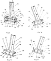
- the control valve includes a first valve body 120 and a first valve core, a first baffle 115 is arranged in the first valve body 120 to divide the first valve body 120 into a first left cavity 107 and a first right cavity 109, the first valve core is mainly composed of a first left valve piece 117 and a first right valve piece 119, which are installed on both ends of a first rotating shaft 12, a first rod containing cavity opening 101 is formed in the first left cavity 107, a first rodless cavity opening 104 is formed in the first right cavity 109, a first left valve cover 116 and a first right valve cover 118 are respectively installed on the outer sides of the first left valve piece 117 and the first right valve piece 119, the first left valve cover 116 is provided with a first ejection outlet 105 and a first color paste bucket opening 106, the first right valve cover 118 is provided with a first channel E 123 and a first channel F 122, the first valve core is rotated to different angular positions to
- An operation method of the three-stage variable color paste pump includes: (1) differentially ejecting a small amount of color paste, wherein at the angular position 1, during the ejection of the first rodless cavity 103, the first rodless cavity opening 104 communicates with the first channel C 114 in the first right valve piece 119, the first channel C 114 communicates with the first channel E 123, the first channel E 123 communicates with the first ejection outlet 105 through the first channel I 111, the first ejection outlet 105 communicates with the first channel B 112, and the first channel B 112 communicates with the first rod containing cavity opening 101; (2) ejecting a medium amount of color paste, wherein at the angular position 2, during the ejection of the first rod containing cavity 102, the first rod containing cavity opening 101 communicates with the first ejection outlet 105 through the first channel A 110, the first rodless cavity opening 104 communicates with the first channel F 122 through the first channel D 113, and the first channel F 122 communicates with the
- an angular position 4 of the communication structure is additionally arranged, in which the first rodless cavity opening 104 communicates with the first channel C 114 in the first right valve piece 119, the first channel C 114 communicates with the first channel F 122, and the first channel F 122 communicates with the first color paste bucket opening 106 through the first channel II 108; and the first rod containing cavity opening 101 communicates with the first channel B 112 in the first left valve piece 117 and the first color paste bucket opening 106, and the first ejection outlet 105 is closed.
- An operation method of the three-stage variable color paste pump includes: (1) differentially ejecting a small amount of color paste, wherein at the angular position 4, when the first rodless cavity 103 sucks in the color paste, the first rodless cavity opening 14 communicates with the first channel C 114 in the first right valve piece 119, the first channel C 114 communicates with the first channel F 122, the first channel F 122 communicates with the first color paste bucket opening 106 through the first channel II 108, the first rod containing cavity opening 101 communicates with the first channel B 112 in the first left valve piece 117 and the first color paste bucket opening 106, and the first ejection outlet 105 is closed, at the angular position 1, during the ejection of the first rodless cavity 103, the first rodless cavity opening 104 communicates with the first channel C 114 in the first right valve piece 119, the first channel C 114 communicates with the first channel E 123, the first channel E 123 communicates with the first ejection outlet 105 through the first channel I
- the control valve includes a second valve body 220 and a second valve core, a second baffle 215 is arranged in the second valve body 220 to divide the second valve body 220 into a second left cavity 207 and a second right cavity 209, the second valve core is mainly composed of a second left valve piece 217 and a second right valve piece 219, which are installed on both ends of a second rotating shaft 221, a second rod containing cavity opening 201 is formed in the second left cavity 207, a second rodless cavity opening 204 is formed in the second right cavity 209, a second left valve cover 216 and a second right valve cover 218 are respectively installed on the outer sides of the second left valve piece 217 and the second right valve piece 219, the second left valve cover 216 is provided with a second ejection outlet 205 and a second color paste bucket opening 206, the second right valve cover 218 is provided with a second channel E 223 and a second channel F 222, the second valve core
- An operation method of the three-stage variable color paste pump includes: (1) differentially ejecting a small amount of color paste, wherein at the angular position 1, during the ejection of the second rodless cavity 203, the second rodless cavity opening 24 communicates with the second channel C 214 in the second right valve piece 219, the second channel C 214 communicates with the second channel E 223, the second channel E 223 communicates with the second ejection outlet 205 through the second channel I 211, the second ejection outlet 205 communicates with the second channel B 212, and the second channel B 212 communicates with the second rod containing cavity opening 201; (2) ejecting a medium amount of color paste, wherein at the angular position 2, during the ejection of the second rod containing cavity 202, the second rod containing cavity opening 201 communicates with the second ejection outlet 205 through the second channel A 210, the second rodless cavity opening 204 communicates with the second channel F 222 through the second channel D 213, and the second channel F 222 communicates with
- an angular position 4 of the communication structure is additionally arranged, in which the second rodless cavity opening 204 communicates with the second channel C 214 in the second right valve piece 219, the second channel C 214 communicates with the second channel F 222, and the second channel F 222 communicates with the second color paste bucket opening 206 through the second channel II 208; and the second rod containing cavity opening 201 communicates with the second channel B 212 in the second left valve piece 217 and the second color paste bucket opening 206, and the second ejection outlet 205 is closed.
- An operation method of the three-stage variable color paste pump includes: (1) differentially ejecting a small amount of color paste, wherein at the angular position 4, when the second rodless cavity 203 sucks in the color paste, the second rodless cavity opening 204 communicates with the second channel C 214 in the second right valve piece 219, the second channel C 214 communicates with the second channel F 222, the second channel F 222 communicates with the second color paste bucket opening 206 through the second channel II 208, the second rod containing cavity opening 201 communicates with the second channel B 212 in the second left valve piece 217 and the second color paste bucket opening 206, and the second ejection outlet 205 is closed, at the angular position 1, during the ejection of the second rodless cavity 203, the second rodless cavity opening 204 communicates with the second channel C 214 in the second right valve piece 219, the second channel C 214 communicates with the second channel E 223, the second channel E 223 communicates with the second ejection outlet 205 through the second channel I
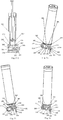
- the control valve includes a third valve body 306 and a third valve core 308, the third valve core 308 is a drum valve core, the third valve body 306 is provided with a third rodless cavity opening A 303, a third rod containing cavity opening A 305, a third rod containing cavity opening B 307, a third rodless cavity opening B 304 and a third ejection outlet 312, a third left cavity 309 and a third right cavity 310 are arranged in the third valve core 308, the third left cavity 309 communicates with a third color paste bucket opening 311, a third channel A 313, a third channel B 314, a third channel C 315 and a third channel D 316 communicating with the third left cavity 309 and a third channel E 317, a third channel F 318, a third channel G 320, a third channel H 319, a third channel I 321, a third channel J 322 and a third channel K 323 communicating with the third right cavity 310 are
- An operation method of the above pump includes: (1) differentially ejecting a small amount of color paste, wherein at the angular position 1, during the ejection of the third rodless cavity 302, the third rodless cavity opening B 304 communicates with the third channel F 318 in the third valve core 308, the third channel F 318 communicates with the third rod containing cavity opening B 307 through the third channel H 319 in the third valve core 308, and the third channel F 318 communicates with the third ejection outlet 312 through the third channel I 321 in the third valve core 308; (2) ejecting a medium amount of color paste, wherein at the angular position 2, during the ejection of the third rod containing cavity 301, the third rodless cavity opening A 303 communicates with the third color paste bucket opening 311 through the third channel D 316 in the third valve core 308, and the third rod containing cavity opening B 307 communicates with the third ejection outlet 312 through the third channel G 320 and the third channel K 323 in the third valve core 308; and (3)
- an angular position 4 of the communication structure is additionally arranged, in which the third rod containing cavity opening A 305 communicates with the third color paste bucket opening 312 through a third channel A 313 in the third valve core 308, the third rodless cavity opening A 303 communicates with the third color paste bucket opening 311 through a third channel C 315 in the third valve core 308, and the third ejection outlet 312 is closed.
- An operation method of the three-stage variable color paste pump includes: (1) differentially ejecting a small amount of color paste, wherein at the angular position 4, when the third rodless cavity 302 sucks in the color paste, the third rod containing cavity opening A 305 communicates with the third color paste bucket opening 311 through the third channel A 313 in the third valve core 308, the third rodless cavity opening A 303 communicates with the third color paste bucket opening 311 through the third channel C 315 in the third valve core 308, and the third ejection outlet 312 is closed, at the angular position 1, during the ejection of the third rodless cavity 302, the third rodless cavity opening B 304 communicates with the third channel F 318 in the third valve core 308, the third channel F 318 communicates with the third rod containing cavity opening B 307 through the third channel H 319 in the third valve core 308, and the third channel F 318 communicates with the third ejection outlet 312 through the third channel I 321 in the third valve core 308; (2) ejecting a
- the control valve includes a fourth valve body 403 and a fourth valve core 404
- the fourth valve body 403 is provided with a fourth rod containing cavity opening 405, a fourth rodless cavity opening A 412, a fourth rodless cavity opening B 406, a fourth rodless cavity opening C 411 and a fourth ejection outlet
- the fourth rod containing cavity opening 405 communicates with a fourth channel II 408 through a fourth channel I 407
- a fourth left cavity 414 and a fourth right cavity 415 are arranged in the fourth valve core 404
- the fourth left cavity 414 communicates with a fourth color paste bucket opening 413, a fourth channel A 416, a fourth channel B 409, a fourth channel C 418, a fourth channel H 423 and a fourth channel K 417 communicating with the fourth left cavity 414
- a fourth channel G 422 a fourth channel F 421, a fourth channel E 420, a fourth channel I 424 and a fourth channel J 410 communicating with the fourth right cavity 415
- An operation method of the three-stage variable color paste pump includes: (1) differentially ejecting a small amount of color paste, wherein at the angular position 1, during the ejection of the fourth rodless cavity 402, the fourth rodless cavity opening B 406 communicates with the fourth channel II 408 through the fourth channel D 419 in the fourth valve core 404, and the fourth rodless cavity opening C 411 communicates with the fourth ejection outlet through the fourth channel G 422 and the fourth channel E 420 in the fourth valve core 404; (2) ejecting a medium amount of color paste, wherein at the angular position 2, during the ejection of the fourth rod containing cavity 401, the fourth rodless cavity opening B 406 communicates with the fourth color paste bucket opening 413 through the fourth channel K 417 in the fourth valve core 404, the fourth rod containing cavity opening 405 communicates with the fourth channel I 407, the fourth channel I 407 communicates with the fourth channel II 408, and the fourth channel II 408 communicates with the fourth ejection outlet through the fourth channel H 423
- an angular position 4 of the communication structure is additionally arranged, in which the fourth rodless cavity opening A 412 communicates with the fourth color paste bucket opening 413 through a fourth channel A 416 in the fourth valve core 404, the fourth rod containing cavity opening 405 communicates with the fourth channel I 407, the fourth channel I 407 communicates with the fourth channel II 408, the fourth channel II 408 communicates with the fourth color paste bucket opening 413 through a fourth channel B 409 in the fourth valve core 404, and the fourth ejection outlet is closed.
- An operation method of the three-stage variable color paste pump includes: (1) differentially ejecting a small amount of color paste, wherein at the angular position 4, when the fourth rodless cavity 402 sucks in the color paste, the fourth rodless cavity opening A 412 communicates with the fourth color paste bucket opening 413 through the fourth channel A 416 in the fourth valve core 404, the fourth rod containing cavity opening 405 communicates with the fourth channel I 407, the fourth channel I 407 communicates with the fourth channel II 408, the fourth channel II 408 communicates with the fourth color paste bucket opening 413 through the fourth channel B 409 in the fourth valve core 404, and the fourth ejection outlet is closed, at the angular position 1, during the ejection of the fourth rodless cavity 402, the fourth rodless cavity opening B 406 communicates with the fourth channel II 408 through the fourth channel D 419 in the fourth valve core 404, and the fourth rodless cavity opening C 411 communicates with the fourth ejection outlet through the fourth channel G 422 and the fourth channel E 420 in the
- the control valve includes a fifth valve body 503, a fifth bonnet 505 and a fifth valve core 516, the fifth bonnet 505 is fixed on the fifth valve body 503, the fifth valve core 516 is connected through a rotating shaft, a fifth cavity 525 is formed between the fifth valve core 516 and the fifth bonnet 505, the fifth valve body 503 is provided with a fifth color paste bucket branch opening a 510, a fifth color paste bucket branch opening b 511, a fifth rod containing cavity branch opening b 515, a fifth rod containing cavity branch opening a 514 and a fifth rodless cavity opening 513, the fifth color paste bucket branch opening a 510 and the fifth color paste bucket branch opening b 511 communicate with the fifth color paste bucket opening 504, the fifth rod containing cavity branch opening b 515 communicates with the fifth rod containing cavity 501 through a fifth channel I 507, the fifth rod containing cavity branch opening b 515 communicates with the fifth rod containing cavity 501 through a fifth channel I 507, the fifth rod containing cavity
- the fifth valve core 516 is rotated to different angular positions to form the following communication structures: as shown in Fig.5a , at an angular position 1, the fifth rodless cavity opening 513 communicates with the fifth cavity 525 through a fifth channel E 522 in the fifth valve core 516, the fifth rod containing cavity branch opening b 515 communicates with the fifth cavity 525 through a fifth channel F 523 in the fifth valve core 516, and the fifth cavity 525 communicates with the fifth ejection outlet 509; as shown in Fig.5b , at an angular position 2, the fifth rodless cavity opening 513 communicates with the fifth color paste bucket branch opening b 511 through a groove 524 in the fifth valve core 516, and the fifth rod containing cavity branch opening b 515 communicates with the fifth ejection outlet 509 through a fifth channel E 522 in the fifth valve core 516; and as shown in Fig.5c , at an angular position 3, the fifth rod containing cavity branch opening a 514 communicates with the fifth color
- An operation method of the three-stage variable color paste pump includes: (1) differentially ejecting a small amount of color paste, wherein at the angular position 1, during the ejection of the fifth rodless cavity 502, the fifth rodless cavity opening 513 communicates with the fifth cavity 525 through the fifth channel E 522 in the fifth valve core 516, the fifth rod containing cavity branch opening b 515 communicates with the fifth cavity 525 through the fifth channel F 523 in the fifth valve core 516, and the fifth cavity 525 communicates with the fifth ejection outlet 509; (2) ejecting a medium amount of color paste, wherein at the angular position 2, during the ejection of the fifth rod containing cavity 501, the fifth rodless cavity opening 513 communicates with the fifth color paste bucket branch opening b 511 through the groove 524 in the fifth valve core 516, and the fifth rod containing cavity branch opening b 515 communicates with the fifth ejection outlet 509 through the fifth channel E 522 in the fifth valve core 516; and (3) ejecting a
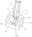
- the control valve includes a sixth valve body 603 and a sixth valve core 604, the sixth valve body 603 is provided with a sixth color paste bucket opening 605, a sixth ejection outlet 606, a sixth rod containing cavity opening 607 and a sixth rodless cavity opening 608, and the sixth valve core 604 is rotated to different angular positions to form the following communication structures: as shown in Fig.6a , at an angular position 1, the sixth rod containing cavity opening 607 communicates with a sixth channel A 611, the sixth channel A 611 communicates with a sixth channel B 612, the sixth channel B 612 communicates with the sixth ejection outlet 606, the sixth rodless cavity opening 608 communicates with the sixth rod containing cavity opening 607 through the sixth channel A 611, and the sixth rod containing cavity opening 607 communicates with the sixth channel B 612; as shown in Fig.6b , at an angular position 2, the sixth rod containing cavity opening 607 communicates with the sixth ejection outlet 606 through
- the sixth channel A 611, the sixth channel B 612, a sixth channel C 616, a sixth channel D 615, a sixth channel E 614, a sixth channel F 613, a sixth channel H 610 ad a sixth channel I 609 can be arranged in the sixth valve core 604 and can also be arranged on the surface of the sixth valve core 604.
- An operation method of the three-stage variable color paste pump includes: (1) differentially ejecting a small amount of color paste, wherein at the angular position 1, during the ejection of the sixth rodless cavity 602, the sixth rod containing cavity opening 607 communicates with the sixth channel A 611, the sixth channel A 611 communicates with the sixth channel B 612, the sixth channel B 612 communicates with the sixth ejection outlet 606, the sixth rodless cavity opening 608 communicates with the sixth rod containing cavity opening 607 through the sixth channel A 611, and the sixth rod containing cavity opening 607 communicates with the sixth channel B 612; (2) ejecting a medium amount of color paste, wherein at the angular position 2, during the ejection of the sixth rod containing cavity 601, the sixth rod containing cavity opening 607 communicates with the sixth ejection outlet 606 through the sixth channel C 616, and the sixth rodless cavity opening 608 communicates with the sixth color paste bucket opening 605 through the sixth channel D 615; and (3) ejecting a large amount of
- an angular position 4 of the communication structure is additionally arranged, in which the sixth rodless cavity opening 608 communicates with the sixth channel H 610, the sixth channel H 610 communicates with the sixth color paste bucket opening 605 through the sixth channel I 609, and the sixth rod containing cavity opening 607 communicates with the sixth color paste bucket opening 605 through the sixth channel I 609.
- An operation method of the three-stage variable color paste pump includes: (1) differentially ejecting a small amount of color paste, wherein at the angular position 4, when the sixth rodless cavity 602 sucks in the color paste, the sixth rodless cavity opening 608 communicates with the sixth channel H 610, the sixth channel H 610 communicates with the sixth color paste bucket opening 605 through the sixth channel I 609, and the sixth rod containing cavity opening 607 communicates with the sixth color paste bucket opening 605 through the sixth channel I 609, at the angular position 1, during the ejection of the sixth rodless cavity 602, the sixth rod containing cavity opening 607 communicates with the sixth channel A 611, the sixth channel A 611 communicates with the sixth channel B 612, the sixth channel B 612 communicates with the sixth ejection outlet 606, the sixth rodless cavity opening 608 communicates with the sixth rod containing cavity opening 607 through the sixth channel A 611, and the sixth rod containing cavity opening 607 communicates with the sixth channel B 612; (2) ejecting a
- the control valve includes a seventh valve body 701 and a seventh valve core 715, the seventh valve core 715 slides in the seventh valve body 701, the seventh valve body 701 is provided with a seventh rod containing cavity opening 702, a seventh rodless cavity opening 703, a seventh color paste bucket opening 707 and a seventh ejection outlet 708, and the seventh valve core 715 is rotated to different positions to form the following communication structures: at the position 1, the seventh rod containing cavity opening 702 communicates with a seventh channel B 716 through a seventh channel A 706, and the seventh rodless cavity opening 703 communicates with the seventh ejection outlet 708 through the seventh channel B 716; at the position 2, the seventh rodless cavity opening 703 communicates with the seventh color paste bucket opening 707 through a seventh channel E 710, and the seventh rod containing cavity opening 702 communicates with the seventh ejection outlet 708 through a seventh channel F 713; and at the position 3, the seventh rod containing cavity opening 702 communicates with the seventh color paste bucket opening 7
- An operation method of the three-stage variable color paste pump includes: (1) differentially ejecting a small amount of color paste, wherein at the position 1, during the ejection of the seventh rodless cavity 705, the seventh rod containing cavity opening 702 communicates with the seventh channel B 716 through the seventh channel A 706, and the seventh rodless cavity opening 703 communicates with the seventh ejection outlet 708 through the seventh channel B 716; (2) ejecting a medium amount of color paste, wherein at the position 2, during the ejection of the seventh rod containing cavity 704, the seventh rodless cavity opening 703 communicates with the seventh color paste bucket opening 707 through the seventh channel E 710, and the seventh rod containing cavity opening 702 communicates with the seventh ejection outlet 708 through the seventh channel F 713; and (3) ejecting a large amount of color paste, wherein at the position 3, during the ejection of the seventh rodless cavity 705, the seventh rod containing cavity opening 702 communicates with the seventh color paste bucket opening 707 through the seventh channel G 714, and the seventh
- a position 4 of the communication structure is additionally arranged, in which the seventh rod containing cavity opening 702 communicates with the seventh color paste bucket opening 707 through a seventh channel C 712, and the seventh rodless cavity opening 703 communicates with the seventh color paste bucket opening 707 through a seventh channel D 709.
- An operation method of the three-stage variable color paste pump includes: (1) differentially ejecting a small amount of color paste, wherein at the position 4, when the seventh rodless cavity 705 sucks in the color paste, the seventh rod containing cavity opening 702 communicates with the seventh color paste bucket opening 707 through the seventh channel C 712, and the seventh rodless cavity opening 703 communicates with the seventh color paste bucket opening 707 through the seventh channel D 709, at the position 1, during the ejection of the seventh rodless cavity 705, the seventh rod containing cavity opening 702 communicates with the seventh channel B 716 through the seventh channel A 706, and the seventh rodless cavity opening 703 communicates with the seventh ejection outlet 708 through the seventh channel B 716; (2) ejecting a medium amount of color paste, wherein at the position 4, when the seventh rod containing cavity 704 sucks in the color paste, the seventh rod containing cavity opening 702 communicates with the seventh color paste bucket opening 707 through the seventh channel C 712, and the seventh rodless cavity opening 703 communicates
- the control valve includes an eighth valve body 801 and an eighth valve core 815
- the eighth valve body 801 includes an upper valve body and a lower valve body
- the eighth valve core 815 is installed between the upper valve body and the lower valve body
- the eighth valve body 801 is provided with an eighth rod containing cavity opening 802, an eighth rodless cavity opening 803, an eighth color paste bucket opening 807 and an eighth ejection outlet 808, and the eighth valve core 815 is rotated to different angular positions to form the following communication structures: as shown in Fig.8a , at an angular position 1, the eighth rod containing cavity opening 802 communicates with an eighth channel B 816 through an eighth channel A 806, and the eighth rodless cavity opening 803 communicates with the eighth ejection outlet 808 through the eighth channel B 816; as shown in Fig.8b , at an angular position 2, the eighth rodless cavity opening 803 communicates with the eighth color paste bucket opening 807 through an eighth channel E 814, and the eighth rod containing cavity opening 803 communicate
- An operation method of the three-stage variable color paste pump includes: (1) differentially ejecting a small amount of color paste, wherein at the angular position 1, the eighth rod containing cavity opening 802 communicates with the eighth channel B 816 through the eighth channel A 806, and the eighth rodless cavity opening 803 communicates with the eighth ejection outlet 808 through the eighth channel B 816; (2) ejecting a medium amount of color paste, wherein at the angular position 2, during the ejection of the eighth rod containing cavity, the eighth rodless cavity opening 803 communicates with the eighth color paste bucket opening 807 through the eighth channel E 810, and the eighth rod containing cavity opening 802 communicates with the eighth ejection outlet 808 through the eighth channel F 813; and (3) ejecting a large amount of color paste, wherein at the angular position 3, during the ejection of the eighth rodless cavity 805, the eighth rod containing cavity opening 802 communicates with the eighth color paste bucket opening 807 through the eighth channel G 814, and the eighth rodless cavity opening 80
- an angular position 4 of the communication structure is additionally arranged, in which the eighth rod containing cavity opening 802 communicates with the eighth color paste bucket opening 807 through an eighth channel C 812, and the eighth rodless cavity opening 803 communicates with the eighth color paste bucket opening 807 through an eighth channel D 809.
- An operation method of the three-stage variable color paste pump includes: (1) differentially ejecting a small amount of color paste, wherein at the angular position 4, when the eighth rodless cavity sucks in the color paste, the eighth rod containing cavity opening 802 communicates with the eighth color paste bucket opening 807 through the eighth channel C 812, and the eighth rodless cavity opening 803 communicates with the eighth color paste bucket opening 807 through the eighth channel D 809, at the angular position 1, the eighth rod containing cavity opening 802 communicates with the eighth channel B 816 through the eighth channel A 806, and the eighth rodless cavity opening 803 communicates with the eighth ejection outlet 808 through the eighth channel B 816; (2) ejecting a medium amount of color paste, wherein at the angular position 4, when the eighth rod containing cavity sucks in the color paste, the eighth rod containing cavity opening 802 communicates with the eighth color paste bucket opening 807 through the eighth channel C 812, and the eighth rodless cavity opening 803 communicates with the eighth color paste bucket opening 8
Landscapes
- Engineering & Computer Science (AREA)
- Mechanical Engineering (AREA)
- General Engineering & Computer Science (AREA)
- Coating Apparatus (AREA)
- Multiple-Way Valves (AREA)
- Details Of Reciprocating Pumps (AREA)
- Reciprocating Pumps (AREA)
- Beverage Vending Machines With Cups, And Gas Or Electricity Vending Machines (AREA)
- Apparatus For Making Beverages (AREA)
- Vending Machines For Individual Products (AREA)
Description
- The present invention belongs to the field of toning equipment, and in particular to a three-stage variable color paste pump and an operation method thereof.
- Toning has strict requirements on the amount of color paste. It is required that the error of the ejection amount of color paste should not exceed a certain percentage when a pump ejects a large amount of color paste, and the error of the ejection amount of color paste should not exceed a certain percentage when a small amount of color paste is ejected as well. However, an existing reciprocating pump for ejecting a large amount of color paste may cause a relatively large ejection deviation when ejecting a small amount of color paste due to the large ejection amount in a unit travel, even if a small deviation occurs on the pump travel, thus causing color abnormality and failing to meet the product demands. Therefore, as to the color paste ejection precision control standard of the toning equipment, the precision requirements of ejecting a small amount of color paste are lower than those of ejecting a large amount of color paste. The current solution is mainly to provide two color mixers at the same time, wherein one color mixer composed of a large pump is mainly responsible for ejecting a large amount of color paste, and the other color mixer composed of a small pump is responsible for ejecting a small amount of color paste. Although this can well solve the problem of controlling the amount of the pumped color paste, as the two color mixers are provided, a lot of money is spent, and a large space is also required, thereby being inconvenient to use, not meeting the needs of modern economic intensive production, and particularly unsuitable for use in storefronts; and another solution is to co-use a large pump with a large section cylinder and a small pump with a small section cylinder in parallel in the same pump and to arrange two pumping systems including one for ejection a large amount of color paste and the other for injecting a small amount of color paste, which also has the problems that the occupied space is relatively large, the structure is complex and the cost is high.
-
Document CN 105 756 979 A discloses a pump capable of outpouring color paste in a large amount or in a trace amount. - In order to overcome the shortcomings of the prior art, the present invention provides a three-stage variable color paste pump, which occupies a small space and has a small ejection amount deviation of color paste, and an operation method thereof.
- The present invention adopts the following technical solution: a three-stage variable color paste pump according to claim 1, which includes a differential pump, the differential pump includes a rodless cavity, a rod containing cavity and a piston rod, a control valve is provided, the control valve includes a valve body and a valve core, the valve body is provided with a rod containing cavity opening for communicating with the rod containing cavity, is provided with a rodless cavity opening for communicating with the rodless cavity, is provided with a color paste bucket opening for communicating with a color paste bucket, and is provided with an ejection outlet, a channel is arranged on the valve core, and the valve core is moved to different positions to form the following communication structures: at a position 1, the rodless cavity communicates with the ejection outlet, and the rodless cavity communicates with the rod containing cavity; at a position 2, the rod containing cavity opening communicates with the ejection outlet, and the rodless cavity communicates with the color paste bucket; and at a position 3, the rodless cavity communicates with the ejection outlet, and the rod containing cavity communicates with the color paste bucket.
- A position 4 of the communication structure may additionally be arranged, in which both of the rodless cavity opening and the rod containing cavity opening communicate with the color paste bucket, and the ejection outlet is closed.
- An operation method of the above pump is defined in
claim 11 and includes: (1) differentially ejecting a small amount of color paste, wherein at the position 1, during the ejection of the rodless cavity, the rodless cavity communicates with the ejection outlet, and the rodless cavity communicates with the rod containing cavity; (2) ejecting a medium amount of color paste, wherein at the position 2, during the ejection of the rod containing cavity, the rod containing cavity opening communicates with the ejection outlet, and the rodless cavity communicates with the color paste bucket; and (3) ejecting a large amount of color paste, wherein and at the position 3, during the ejection of the rodless cavity, the rodless cavity communicates with the ejection outlet, and the rod containing cavity communicates with the color paste bucket. - An operation method of the above pump may include: (1) differentially ejecting a small amount of color paste, wherein at the position 4, when the second rodless cavity sucks in the color paste, both of the rodless cavity opening and the rod containing cavity opening communicate with the color paste bucket, at the position 1, during the ejection of the rodless cavity, the rodless cavity communicates with the ejection outlet, and the rodless cavity communicates with the rod containing cavity; (2) ejecting a medium amount of color paste, wherein at the position 4, when the rod containing cavity sucks in the color paste, both of the rod containing cavity opening and the rodless cavity opening communicate with the color paste bucket, and at the position 2, during the ejection of the rod containing cavity, the rod containing cavity opening communicates with the ejection outlet, and the rodless cavity communicates with the color paste bucket; and (3) ejecting a large amount of color paste, wherein at the position 4, when the second rodless cavity sucks in the color paste, both of the rodless cavity opening and the rod containing cavity opening communicate with the color paste bucket, and at the position 3, during the ejection of the rodless cavity, the rodless cavity communicates with the ejection outlet, and the rod containing cavity communicates with the color paste bucket.
- The control valve may include a first valve body and a first valve core, a first baffle may be arranged in the first valve body to divide the first valve body into a first left cavity and a first right cavity, the first valve core may mainly be composed of a first left valve piece and a first right valve piece, which are installed on both ends of a first rotating shaft, a first rod containing cavity opening may be formed in the first left cavity, a first rodless cavity opening may be formed in the first right cavity, a first left valve cover and a first right valve cover may respectively be installed on the outer sides of the first left valve piece and the first right valve piece, the first left valve cover may be provided with a first ejection outlet and a first color paste bucket opening, the first right valve cover may be provided with a first channel E and a first channel F, the first valve core may be rotated to different angular positions to form the following communication structures: at an angular position 1, the first rodless cavity opening may communicate with a first channel C in the first right valve piece, the first channel C may communicate with the first channel E, the first channel E may communicate with the first ejection outlet through a first channel I, the first ejection outlet may communicate with a first channel B, and the first channel B may communicate with the first rod containing cavity opening; at an angular position 2, the first rod containing cavity opening may communicate with the first ejection outlet through a first channel A, the first rodless cavity opening may communicate with the first channel F through a first channel D, and the first channel F may communicate with the first color paste bucket opening through a first channel II; at an angular position 3, the first rodless cavity opening may communicate with the first channel D, the first channel D may communicate with the first channel E, the first channel E may communicate with the first ejection outlet through the first channel I, and the first rod containing cavity opening may communicate with the first color paste bucket opening through the first channel A; and the first channel I and the first channel II may be arranged in parallel.
- An angular position 4 of the communication structure may additionally be arranged, in which the first rodless cavity opening may communicate with the first channel C in the first right valve piece, the first channel C may communicate with the first channel F, and the first channel F may communicate with the first color paste bucket opening through the first channel II; and the first rod containing cavity opening may communicate with the first channel B in the first left valve piece and the first color paste bucket opening, and the first ejection outlet is closed.
- An operation method of the above pump may include: (1) differentially ejecting a small amount of color paste, wherein at the angular position 1, during the ejection of the first rodless cavity, the first rodless cavity opening communicates with the first channel C in the first right valve piece, the first channel C communicates with the first channel E, the first channel E communicates with the first ejection outlet through the first channel I, the first ejection outlet communicates with the first channel B, and the first channel B communicates with the first rod containing cavity opening; (2) ejecting a medium amount of color paste, wherein at the angular position 2, during the ejection of the first rod containing cavity, the first rod containing cavity opening communicates with the first ejection outlet through the first channel A, the first rodless cavity opening communicates with the first channel F through the first channel D, and the first channel F communicates with the first color paste bucket opening through the first channel II; and (3) ejecting a large amount of color paste, wherein at the angular position 3, during the ejection of the first rodless cavity, the first rodless cavity opening communicates with the first channel D, the first channel D communicates with the first channel E, the first channel E communicates with the first ejection outlet through the first channel I, and the first rod containing cavity opening communicates with the first color paste bucket opening through the first channel A.
- An operation method of the above pump may include: (1) differentially ejecting a small amount of color paste, wherein at the angular position 4, when the first rodless cavity sucks in the color paste, the first rodless cavity opening communicates with the first channel C in the first right valve piece, the first channel C communicates with the first channel F, the first channel F communicates with the first color paste bucket opening through the first channel II, the first rod containing cavity opening communicates with the first channel B in the first left valve piece and the first color paste bucket opening, and the first ejection outlet is closed, at the angular position 1, during the ejection of the first rodless cavity, the first rodless cavity opening communicates with the first channel C in the first right valve piece, the first channel C communicates with the first channel E, the first channel E communicates with the first ejection outlet through the first channel I, the first ejection outlet communicates with the first channel B, and the first channel B communicates with the first rod containing cavity opening; (2) ejecting a medium amount of color paste, wherein at the angular position 4, when the first rod containing cavity sucks in the color paste, the first rodless cavity opening communicates with the first channel C in the first right valve piece, the first channel C communicates with the first channel F, the first channel F communicates with the first color paste bucket opening through the first channel II, the first rod containing cavity opening communicates with the first channel B in the first left valve piece and the first color paste bucket opening, and the first ejection outlet is closed, at the angular position 2, during the ejection of the first rod containing cavity, the first rod containing cavity opening communicates with the first ejection outlet through the first channel A, the first rodless cavity opening communicates with the first channel F through the first channel D, and the first channel F communicates with the first color paste bucket opening through the first channel II; and (3) ejecting a large amount of color paste, wherein at the angular position 4, when the first rodless cavity sucks in the color paste, the first rodless cavity opening communicates with the first channel C in the first right valve piece, the first channel C communicates with the first channel F, the first channel F communicates with the first color paste bucket opening through the first channel II, the first rod containing cavity opening communicates with the first channel B in the first left valve piece and the first color paste bucket opening, and the first ejection outlet is closed, at the angular position 3, during the ejection of the first rodless cavity, the first rodless cavity opening communicates with the first channel D, the first channel D communicates with the first channel E, the first channel E communicates with the first ejection outlet through the first channel I, and the first rod containing cavity opening communicates with the first color paste bucket opening through the first channel A.
- The control valve may include a second valve body and a second valve core, a second baffle may be arranged in the second valve body to divide the second valve body into a second left cavity and a second right cavity, the second valve core may mainly be composed of a second left valve piece and a second right valve piece, which are installed on both ends of a second rotating shaft, a second rod containing cavity opening may be formed in the second left cavity, a second rodless cavity opening may be formed in the second right cavity, a second left valve cover and a second right valve cover may respectively be installed on the outer sides of the second left valve piece and the second right valve piece, the second left valve cover may be provided with a second ejection outlet and a second color paste bucket opening, the second right valve cover may be provided with a second channel E and a second channel F, the second valve core may be rotated to different angular positions to form the following communication structures: at an angular position 1, the second rodless cavity opening may communicate with a second channel C in the second right valve piece, the second channel C may communicate with the second channel E, the second channel E may communicate with the second ejection outlet through a second channel I, the second ejection outlet may communicate with a second channel B, and the second channel B may communicate with the second rod containing cavity opening; at an angular position 2, the second rod containing cavity opening may communicate with the second ejection outlet through a second channel A, the second rodless cavity opening may communicate with the second channel F through a second channel D, and the second channel F may communicate with the second color paste bucket opening through a second channel II; at an angular position 3, the second rodless cavity opening may communicate with the second channel D, the second channel D may communicate with the second channel E, the second channel E may communicate with the second ejection outlet through the second channel I, and the second rod containing cavity opening may communicate with the second color paste bucket opening through the second channel A; and the second channel I and the second channel II may be arranged in a crossing manner.
- An angular position 4 of the communication structure may additionally be arranged, in which the second rodless cavity opening communicates with the second channel C in the second right valve piece, the second channel C communicates with the second channel F, and the second channel F communicates with the second color paste bucket opening through the second channel II; and the second rod containing cavity opening communicates with the second channel B in the second left valve piece and the second color paste bucket opening, and the second ejection outlet is closed.
- An operation method of the above pump may include: (1) differentially ejecting a small amount of color paste, wherein at the angular position 1, during the ejection of the second rodless cavity, the second rodless cavity opening communicates with the second channel C in the second right valve piece, the second channel C communicates with the second channel E, the second channel E communicates with the second ejection outlet through the second channel I, the second ejection outlet communicates with the second channel B, and the second channel B communicates with the second rod containing cavity opening; (2) ejecting a medium amount of color paste, wherein at the angular position 2, during the ejection of the second rod containing cavity, the second rod containing cavity opening communicates with the second ejection outlet through the second channel A, the second rodless cavity opening communicates with the second channel F through the second channel D, and the second channel F communicates with the second color paste bucket opening through the second channel II; and (3) ejecting a large amount of color paste, wherein at the angular position 3, during the ejection of the second rodless cavity, the second rodless cavity opening communicates with the second channel D, the second channel D communicates with the second channel E, the second channel E communicates with the second ejection outlet through the second channel I, and the second rod containing cavity opening communicates with the second color paste bucket opening through the second channel A.
- An operation method of the above pump may include: (1) differentially ejecting a small amount of color paste, wherein at the angular position 4, when the second rodless cavity sucks in the color paste, the second rodless cavity opening communicates with the second channel C in the second right valve piece, the second channel C communicates with the second channel F, the second channel F communicates with the second color paste bucket opening through the second channel II, the second rod containing cavity opening communicates with the second channel B in the second left valve piece and the second color paste bucket opening, and the second ejection outlet is closed, at the angular position 1, during the ejection of the second rodless cavity, the second rodless cavity opening communicates with the second channel C in the second right valve piece, the second channel C communicates with the second channel E, the second channel E communicates with the second ejection outlet through the second channel I, the second ejection outlet communicates with the second channel B, and the second channel B communicates with the second rod containing cavity opening; (2) ejecting a medium amount of color paste, wherein at the angular position 4, when the second rod containing cavity sucks in the color paste, the second rodless cavity opening communicates with the second channel C in the second right valve piece, the second channel C communicates with the second channel F, the second channel F communicates with the second color paste bucket opening through the second channel II, the second rod containing cavity opening communicates with the second channel B in the second left valve piece and the second color paste bucket opening, and the second ejection outlet is closed, at the angular position 2, during the ejection of the second rod containing cavity, the second rod containing cavity opening communicates with the second ejection outlet through the second channel A, the second rodless cavity opening communicates with the second channel F through the second channel D, and the second channel F communicates with the second color paste bucket opening through the second channel II; and (3) ejecting a large amount of color paste, wherein at the angular position 4, when the second rodless cavity sucks in the color paste, the second rodless cavity opening communicates with the second channel C in the second right valve piece, the second channel C communicates with the second channel F, the second channel F communicates with the second color paste bucket opening through the second channel II, the second rod containing cavity opening communicates with the second channel B in the second left valve piece and the second color paste bucket opening, and the second ejection outlet is closed, at the angular position 3, during the ejection of the second rodless cavity, the second rodless cavity opening communicates with the second channel D, the second channel D communicates with the second channel E, the second channel E communicates with the second ejection outlet through the second channel I, and the second rod containing cavity opening communicates with the second color paste bucket opening through the second channel A.
- The control valve may include a third valve body and a third valve core, the third valve body may be provided with a third rodless cavity opening A, a third rod containing cavity opening A, a third rod containing cavity opening B, a third rodless cavity opening B and a third ejection outlet, a third left cavity and a third right cavity may be arranged in the third valve core, the third left cavity may communicate with a third color paste bucket opening, and the third valve core may be rotated to different angular positions to form the following communication structures: at an angular position 1, the third rodless cavity opening B may communicate with a third channel F in the third valve core, the third channel F may communicate with the third rod containing cavity opening B through a third channel H in the third valve core, and the third channel F may communicate with the third ejection outlet through a third channel I in the third valve core; at an angular position 2, the third rodless cavity opening A may communicate with the third color paste bucket opening through a third channel D in the third valve core, and the third rod containing cavity opening B may communicate with the third ejection outlet through a third channel G and a third channel K in the third valve core; and at an angular position 3, the third rod containing cavity opening A may communicate with the third color paste bucket opening through a third channel B in the third valve core, and the third rodless cavity opening B may communicate with the third ejection outlet through a third channel E and a third channel J in the third valve core.
- An angular position 4 of the communication structure may additionally be arranged, in which the third rod containing cavity opening A communicates with the third color paste bucket opening through a third channel A in the third valve core, the third rodless cavity opening A communicates with the third color paste bucket opening through a third channel C in the third valve core, and the third ejection outlet is closed.
- An operation method of the above pump may include: (1) differentially ejecting a small amount of color paste, wherein at the angular position 1, during the ejection of the third rodless cavity, the third rodless cavity opening B communicates with the third channel F in the third valve core, the third channel F communicates with the third rod containing cavity opening B through the third channel H in the third valve core, and the third channel F communicates with the third ejection outlet through the third channel I in the third valve core; (2) ejecting a medium amount of color paste, wherein at the angular position 2, during the ejection of the third rod containing cavity, the third rodless cavity opening A communicates with the third color paste bucket opening through the third channel D in the third valve core, and the third rod containing cavity opening B communicates with the third ejection outlet through the third channel G and the third channel K in the third valve core; and (3) ejecting a large amount of color paste, wherein at the angular position 3, during the ejection of the third rodless cavity, the third rod containing cavity opening A communicates with the third color paste bucket opening through the third channel B in the third valve core, and the third rodless cavity opening B communicates with the third ejection outlet through the third channel E and the third channel J in the third valve core.
- An operation method of the above pump may include: (1) differentially ejecting a small amount of color paste, wherein at the angular position 4, when the third rodless cavity sucks in the color paste, the third rod containing cavity opening A communicates with the third color paste bucket opening through the third channel A in the third valve core, the third rodless cavity opening A communicates with the third color paste bucket opening through the third channel C in the third valve core, and the third ejection outlet is closed, at the angular position 1, during the ejection of the third rodless cavity, the third rodless cavity opening B communicates with the third channel F in the third valve core, the third channel F communicates with the third rod containing cavity opening B through the third channel H in the third valve core, and the third channel F communicates with the third ejection outlet through the third channel I in the third valve core; (2) ejecting a medium amount of color paste, wherein at the angular position 4, when the third rod containing cavity sucks in the color paste, the third rod containing cavity opening A communicates with the third color paste bucket opening through the third channel A in the third valve core, the third rodless cavity opening A communicates with the third color paste bucket opening through the third channel C in the third valve core, and the third ejection outlet is closed, at the angular position 2, during the ejection of the third rod containing cavity, the third rodless cavity opening A communicates with the third color paste bucket opening through the third channel D in the third valve core, and the third rod containing cavity opening B communicates with the third ejection outlet through the third channel G and the third channel K in the third valve core; and (3) ejecting a large amount of color paste, wherein at the angular position 4, when the third rodless cavity sucks in the color paste, the third rod containing cavity opening A communicates with the third color paste bucket opening through the third channel A in the third valve core, the third rodless cavity opening A communicates with the third color paste bucket opening through the third channel C in the third valve core, and the third ejection outlet is closed, at the angular position 3, during the ejection of the third rodless cavity, the third rod containing cavity opening A communicates with the third color paste bucket opening through the third channel B in the third valve core, and the third rodless cavity opening B communicates with the third ejection outlet through the third channel E and the third channel J in the third valve core.
- The control valve may include a fourth valve body and a fourth valve core, the fourth valve body may be provided with a fourth rod containing cavity opening, a fourth rodless cavity opening A, a fourth rodless cavity opening B, a fourth rodless cavity opening C and a fourth ejection outlet, the fourth rod containing cavity opening may communicate with a fourth channel II through a fourth channel I, a fourth left cavity and a fourth right cavity may be arranged in the fourth valve core, the fourth left cavity may communicate with a fourth color paste bucket opening, and the fourth valve core may be rotated to different angular positions to form the following communication structures: at an angular position 1, the fourth rodless cavity opening B may communicate with the fourth channel II through a fourth channel D in the fourth valve core, and the fourth rodless cavity opening C may communicate with the fourth ejection outlet through a fourth channel G and a fourth channel E in the fourth valve core; at an angular position 2, the fourth rodless cavity opening B may communicate with the fourth color paste bucket opening through a fourth channel K in the fourth valve core, the fourth rod containing cavity opening may communicate with the fourth channel I, the fourth channel I may communicate with the fourth channel II, and the fourth channel II may communicate with the fourth ejection outlet through a fourth channel H; and at an angular position 3, the fourth rod containing cavity opening may communicate with the fourth channel I, the fourth channel I may communicate with the fourth channel II, the fourth channel II may communicate with the fourth color paste bucket opening through a fourth channel C, and the fourth rodless cavity opening C may communicate with the fourth ejection outlet through a fourth channel F and the fourth channel I in the fourth valve core.
- An angular position 4 of the communication structure may additionally be arranged, in which the fourth rodless cavity opening A communicates with the fourth color paste bucket opening through a fourth channel A in the fourth valve core, the fourth rod containing cavity opening communicates with the fourth channel I, the fourth channel I communicates with the fourth channel II, the fourth channel II communicates with the fourth color paste bucket opening through a fourth channel B in the fourth valve core, and the fourth ejection outlet is closed.
- An operation method of the above pump may include: (1) differentially ejecting a small amount of color paste, wherein at the angular position 1, during the ejection of the fourth rodless cavity, the fourth rodless cavity opening B communicates with the fourth channel II through the fourth channel D in the fourth valve core, and the fourth rodless cavity opening C communicates with the fourth ejection outlet through the fourth channel G and the fourth channel E in the fourth valve core; (2) ejecting a medium amount of color paste, wherein at the angular position 2, during the ejection of the fourth rod containing cavity, the fourth rodless cavity opening B communicates with the fourth color paste bucket opening through the fourth channel K in the fourth valve core, the fourth rod containing cavity opening communicates with the fourth channel I, the fourth channel I communicates with the fourth channel II, and the fourth channel II communicates with the fourth ejection outlet through the fourth channel H; and (3) ejecting a large amount of color paste, wherein at the angular position 3, during the ejection of the fourth rodless cavity, the fourth rod containing cavity opening communicates with the fourth channel I, the fourth channel I communicates with the fourth channel II, the fourth channel II communicates with the fourth color paste bucket opening through the fourth channel C, and the fourth rodless cavity opening C communicates with the fourth ejection outlet through the fourth channel F and the fourth channel I in the fourth valve core.
- An operation method of the above pump may include: (1) differentially ejecting a small amount of color paste, wherein at the angular position 4, when the fourth rodless cavity sucks in the color paste, the fourth rodless cavity opening A communicates with the fourth color paste bucket opening through the fourth channel A in the fourth valve core, the fourth rod containing cavity opening communicates with the fourth channel I, the fourth channel I communicates with the fourth channel II, the fourth channel II communicates with the fourth color paste bucket opening through the fourth channel B in the fourth valve core, and the fourth ejection outlet is closed, at the angular position 1, during the ejection of the fourth rodless cavity, the fourth rodless cavity opening B communicates with the fourth channel II through the fourth channel D in the fourth valve core, and the fourth rodless cavity opening C communicates with the fourth ejection outlet through the fourth channel G and the fourth channel E in the fourth valve core; (2) ejecting a medium amount of color paste, wherein at the angular position 4, when the fourth rod containing cavity sucks in the color paste, the fourth rodless cavity opening A communicates with the fourth color paste bucket opening through the fourth channel A in the fourth valve core, the fourth rod containing cavity opening communicates with the fourth channel I, the fourth channel I communicates with the fourth channel II, the fourth channel II communicates with the fourth color paste bucket opening through the fourth channel B in the fourth valve core, and the fourth ejection outlet is closed, at the angular position 2, during the ejection of the fourth rod containing cavity, the fourth rodless cavity opening B communicates with the fourth color paste bucket opening through the fourth channel K in the fourth valve core, the fourth rod containing cavity opening communicates with the fourth channel I, the fourth channel I communicates with the fourth channel II, and the fourth channel II communicates with the fourth ejection outlet through the fourth channel H; and (3) ejecting a large amount of color paste, wherein at the angular position 4, when the fourth rodless cavity sucks in the color paste, the fourth rodless cavity opening A communicates with the fourth color paste bucket opening through the fourth channel A in the fourth valve core, the fourth rod containing cavity opening communicates with the fourth channel I, the fourth channel I communicates with the fourth channel II, the fourth channel II communicates with the fourth color paste bucket opening through the fourth channel B in the fourth valve core, and the fourth ejection outlet is closed, at the angular position 3, during the ejection of the fourth rodless cavity, the fourth rod containing cavity opening communicates with the fourth channel I, the fourth channel I communicates with the fourth channel II, the fourth channel II communicates with the fourth color paste bucket opening through the fourth channel C, and the fourth rodless cavity opening C communicates with the fourth ejection outlet through the fourth channel F and the fourth channel I in the fourth valve core.
- The control valve may include a fifth valve body, a fifth bonnet and a fifth valve core, the fifth bonnet may be fixed on the fifth valve body, the fifth valve core may be connected through a rotating shaft, a fifth cavity may be formed between the fifth valve core and the fifth bonnet, the fifth valve body may be provided with a fifth color paste bucket branch opening a, a fifth color paste bucket branch opening b, a fifth rod containing cavity branch opening b, a fifth rod containing cavity branch opening a and a fifth rodless cavity opening, the fifth color paste bucket branch opening a and the fifth color paste bucket branch opening b may communicate with the fifth color paste bucket opening, the fifth rod containing cavity branch opening b may communicate with the fifth rod containing cavity through a fifth channel I, the fifth rod containing cavity branch opening a may communicate with the fifth rod containing cavity through a fifth channel II, a fifth ejection outlet may be formed in the fifth bonnet, the fifth cavity may communicate with the fifth ejection outlet, a channel may be arranged on the fifth valve core, and the fifth valve core may be rotated to different angular positions to form the following communication structures: at an angular position 1, the fifth rodless cavity opening may communicate with the fifth cavity through a fifth channel E in the fifth valve core, the fifth rod containing cavity branch opening b may communicate with the fifth cavity through a fifth channel F in the fifth valve core, and the fifth cavity may communicate with the fifth ejection outlet; at an angular position 2, the fifth rodless cavity opening may communicate with the fifth color paste bucket branch opening b through a groove in the fifth valve core, and the fifth rod containing cavity branch opening b may communicate with the fifth ejection outlet through a fifth channel E in the fifth valve core; and at an angular position 3, the fifth rod containing cavity branch opening a may communicate with the fifth color paste bucket branch opening a through the groove in the fifth valve core, and the fifth rodless cavity opening may communicate with the fifth ejection outlet through the fifth channel F.
- A static valve piece may be arranged between the fifth valve body and the fifth valve core, a fifth channel a, a fifth channel b, a fifth channel c and a fifth channel d may be arranged in the static valve piece, the fifth channel a may communicate with the fifth rodless cavity opening, the fifth channel b may communicate with the fifth color paste bucket branch opening a and the fifth color paste bucket branch opening b, the fifth channel c may communicate with the fifth rod containing cavity branch opening a, and the fifth channel d may communicate with the fifth rod containing cavity branch opening b.
- An operation method of the above pump may include: (1) differentially ejecting a small amount of color paste, wherein at the angular position 1, during the ejection of the fifth rodless cavity, the fifth rodless cavity opening communicates with the fifth cavity through the fifth channel E in the fifth valve core, the fifth rod containing cavity branch opening b communicates with the fifth cavity through the fifth channel F in the fifth valve core, and the fifth cavity communicates with the fifth ejection outlet; (2) ejecting a medium amount of color paste, wherein at the angular position 2, during the ejection of the fifth rod containing cavity, the fifth rodless cavity opening communicates with the fifth color paste bucket branch opening b through the groove in the fifth valve core, and the fifth rod containing cavity branch opening b communicates with the fifth ejection outlet through the fifth channel E in the fifth valve core; and (3) ejecting a large amount of color paste, wherein at the angular position 3, during the ejection of the fifth rodless cavity, the fifth rod containing cavity branch opening a communicates with the fifth color paste bucket branch opening a through the groove in the fifth valve core, and the fifth rodless cavity opening communicates with the fifth ejection outlet through the fifth channel F.
- The control valve may include a sixth valve body and a sixth valve core, the sixth valve body may be provided with a sixth color paste bucket opening, a sixth ejection outlet, a sixth rod containing cavity opening and a sixth rodless cavity opening, and the sixth valve core may be rotated to different angular positions to form the following communication structures: at an angular position 1, the sixth rod containing cavity opening may communicate with a sixth channel A, the sixth channel A may communicate with a sixth channel B, the sixth channel B may communicate with the sixth ejection outlet, the sixth rodless cavity opening may communicate with the sixth rod containing cavity opening through the sixth channel A, and the sixth rod containing cavity opening may communicate with the sixth channel B; at an angular position 2, the sixth rod containing cavity opening may communicate with the sixth ejection outlet through a sixth channel C, and the sixth rodless cavity opening may communicate with the sixth color paste bucket opening through a sixth channel D; and at an angular position 3, the sixth rodless cavity opening may communicate with the sixth ejection outlet through a sixth channel E, and the sixth rod containing cavity opening may communicate with the sixth color paste bucket opening through a sixth channel F.
- An angular position 4 of the communication structure may additionally be arranged, in which the sixth rodless cavity opening communicates with a sixth channel H, the sixth channel H communicates with the sixth color paste bucket opening through a sixth channel I, and the sixth rod containing cavity opening communicates with the sixth color paste bucket opening through the sixth channel I.
- An operation method of the above pump may include: (1) differentially ejecting a small amount of color paste, wherein at the angular position 1, during the ejection of the sixth rodless cavity, the sixth rod containing cavity opening communicates with the sixth channel A, the sixth channel A communicates with the sixth channel B, the sixth channel B communicates with the sixth ejection outlet, the sixth rodless cavity opening communicates with the sixth rod containing cavity opening through the sixth channel A, and the sixth rod containing cavity opening communicates with the sixth channel B; (2) ejecting a medium amount of color paste, wherein at the angular position 2, during the ejection of the sixth rod containing cavity, the sixth rod containing cavity opening communicates with the sixth ejection outlet through the sixth channel C, and the sixth rodless cavity opening communicates with the sixth color paste bucket opening through the sixth channel D; and (3) ejecting a large amount of color paste, wherein at the angular position 3, during the ejection of the sixth rodless cavity, the sixth rodless cavity opening communicates with the sixth ejection outlet through the sixth channel E, and the sixth rod containing cavity opening communicates with the sixth color paste bucket opening through the sixth channel F.
- An operation method of the above pump may include: (1) differentially ejecting a small amount of color paste, wherein at the angular position 4, when the sixth rodless cavity sucks in the color paste, the sixth rodless cavity opening communicates with the sixth channel H, the sixth channel H communicates with the sixth color paste bucket opening through the sixth channel I, and the sixth rod containing cavity opening communicates with the sixth color paste bucket opening through the sixth channel I, at the angular position 1, during the ejection of the sixth rodless cavity, the sixth rod containing cavity opening communicates with the sixth channel A, the sixth channel A communicates with the sixth channel B, the sixth channel B communicates with the sixth ejection outlet, the sixth rodless cavity opening communicates with the sixth rod containing cavity opening through the sixth channel A, and the sixth rod containing cavity opening communicates with the sixth channel B; (2) ejecting a medium amount of color paste, wherein at the angular position 4, when the sixth rod containing cavity sucks in the color paste, and when the sixth rodless cavity sucks in the color paste, the sixth rodless cavity opening communicates with the sixth channel H, the sixth channel H communicates with the sixth color paste bucket opening through the sixth channel I, and the sixth rod containing cavity opening communicates with the sixth color paste bucket opening through the sixth channel I, at the angular position 2, during the ejection of the sixth rod containing cavity, the sixth rod containing cavity opening communicates with the sixth ejection outlet through the sixth channel C, and the sixth rodless cavity opening communicates with the sixth color paste bucket opening through the sixth channel D; and (3) ejecting a large amount of color paste, wherein at the angular position 4, when the sixth rodless cavity sucks in the color paste, the sixth rodless cavity opening communicates with the sixth channel H, the sixth channel H communicates with the sixth color paste bucket opening through the sixth channel I, and the sixth rod containing cavity opening communicates with the sixth color paste bucket opening through the sixth channel I, at the angular position 3, during the ejection of the sixth rodless cavity, the sixth rodless cavity opening communicates with the sixth ejection outlet through the sixth channel E, and the sixth rod containing cavity opening communicates with the sixth color paste bucket opening through the sixth channel F.
- The control valve may include a seventh valve body and a seventh valve core, the seventh valve body may be provided with a seventh rod containing cavity opening, a seventh rodless cavity opening, a seventh color paste bucket opening and a seventh ejection outlet, and the seventh valve core may be rotated to different positions to form the following communication structures: at the position 1, the seventh rod containing cavity opening may communicate with a seventh channel B through a seventh channel A, and the seventh rodless cavity opening may communicate with the seventh ejection outlet through the seventh channel B; at the position 2, the seventh rodless cavity opening may communicate with the seventh color paste bucket opening through a seventh channel E, and the seventh rod containing cavity opening may communicate with the seventh ejection outlet through a seventh channel F; and at the position 3, the seventh rod containing cavity opening may communicate with the seventh color paste bucket opening through a seventh channel G, and the seventh rodless cavity opening may communicate with the seventh ejection outlet through a seventh channel H.
- A position 4 of the communication structure may additionally be arranged, in which the seventh rod containing cavity opening communicates with the seventh color paste bucket opening through a seventh channel C, and the seventh rodless cavity opening communicates with the seventh color paste bucket opening through a seventh channel D.
- An operation method of the above pump may include: (1) differentially ejecting a small amount of color paste, wherein at the position 1, during the ejection of the seventh rodless cavity, the seventh rod containing cavity opening communicates with the seventh channel B through the seventh channel A, and the seventh rodless cavity opening communicates with the seventh ejection outlet through the seventh channel B; (2) ejecting a medium amount of color paste, wherein at the position 2, during the ejection of the seventh rod containing cavity, the seventh rodless cavity opening communicates with the seventh color paste bucket opening through the seventh channel E, and the seventh rod containing cavity opening communicates with the seventh ejection outlet through the seventh channel F; and (3) ejecting a large amount of color paste, wherein at the position 3, during the ejection of the seventh rodless cavity, the seventh rod containing cavity opening communicates with the seventh color paste bucket opening through the seventh channel G, and the seventh rodless cavity opening communicates with the seventh ejection outlet through the seventh channel H.
- An operation method of the above pump may include: (1) differentially ejecting a small amount of color paste, wherein at the position 4, when the seventh rodless cavity sucks in the color paste, the seventh rod containing cavity opening communicates with the seventh color paste bucket opening through the seventh channel C, and the seventh rodless cavity opening communicates with the seventh color paste bucket opening through the seventh channel D, at the position 1, during the ejection of the seventh rodless cavity, the seventh rod containing cavity opening communicates with the seventh channel B through the seventh channel A, and the seventh rodless cavity opening communicates with the seventh ejection outlet through the seventh channel B; (2) ejecting a medium amount of color paste, wherein at the position 4, when the seventh rod containing cavity sucks in the color paste, the seventh rod containing cavity opening communicates with the seventh color paste bucket opening through the seventh channel C, and the seventh rodless cavity opening communicates with the seventh color paste bucket opening through the seventh channel D, at the position 2, during the ejection of the seventh rod containing cavity, the seventh rodless cavity opening communicates with the seventh color paste bucket opening through the seventh channel E, and the seventh rod containing cavity opening communicates with the seventh ejection outlet through the seventh channel F; and (3) ejecting a large amount of color paste, wherein at the position 4, when the seventh rodless cavity sucks in the color paste, the seventh rod containing cavity opening communicates with the seventh color paste bucket opening through the seventh channel C, and the seventh rodless cavity opening communicates with the seventh color paste bucket opening through the seventh channel D, at the position 3, during the ejection of the seventh rodless cavity, the seventh rod containing cavity opening communicates with the seventh color paste bucket opening through the seventh channel G, and the seventh rodless cavity opening communicates with the seventh ejection outlet through the seventh channel H.
- The control valve may include an eighth valve body and an eighth valve core, the eighth valve body may be provided with an eighth rod containing cavity opening, an eighth rodless cavity opening, an eighth color paste bucket opening and an eighth ejection outlet, and the eighth valve core may be rotated to different angular positions to form the following communication structures: at an angular position 1, the eighth rod containing cavity opening may communicate with an eighth channel B through an eighth channel A, and the eighth rodless cavity opening may communicate with the eighth ejection outlet through the eighth channel B; at an angular position 2, the eighth rodless cavity opening may communicate with the eighth color paste bucket opening through an eighth channel E, and the eighth rod containing cavity opening may communicate with the eighth ejection outlet through an eighth channel F; and at an angular position 3, the eighth rod containing cavity opening may communicate with the eighth color paste bucket opening through an eighth channel G, and the eighth rodless cavity opening may communicate with the eighth ejection outlet through an eighth channel H.
- An angular position 4 of the communication structure may additionally be arranged, in which the eighth rod containing cavity opening communicates with the eighth color paste bucket opening through an eighth channel C, and the eighth rodless cavity opening communicates with the eighth color paste bucket opening through an eighth channel D.
- An operation method of the above pump may include: (1) differentially ejecting a small amount of color paste, wherein at the angular position 1, the eighth rod containing cavity opening communicates with the eighth channel B through the eighth channel A, and the eighth rodless cavity opening communicates with the eighth ejection outlet through the eighth channel B; (2) ejecting a medium amount of color paste, wherein at the angular position 2, during the ejection of the eighth rod containing cavity, the eighth rodless cavity opening communicates with the eighth color paste bucket opening through the eighth channel E, and the eighth rod containing cavity opening communicates with the eighth ejection outlet through the eighth channel F; and (3) ejecting a large amount of color paste, wherein at the angular position 3, during the ejection of the eighth rodless cavity, the eighth rod containing cavity opening communicates with the eighth color paste bucket opening through the eighth channel G, and the eighth rodless cavity opening communicates with the eighth ejection outlet through the eighth channel H.
- An operation method of the above pump may include: (1) differentially ejecting a small amount of color paste, wherein at the angular position 4, when the eighth rodless cavity sucks in the color paste, the eighth rod containing cavity opening communicates with the eighth color paste bucket opening through the eighth channel C, and the eighth rodless cavity opening communicates with the eighth color paste bucket opening through the eighth channel D, at the angular position 1, the eighth rod containing cavity opening communicates with the eighth channel B through the eighth channel A, and the eighth rodless cavity opening communicates with the eighth ejection outlet through the eighth channel B; (2) ejecting a medium amount of color paste, wherein at the angular position 4, when the eighth rod containing cavity sucks in the color paste, the eighth rod containing cavity opening communicates with the eighth color paste bucket opening through the eighth channel C, and the eighth rodless cavity opening communicates with the eighth color paste bucket opening through the eighth channel D, at the angular position 2, during the ejection of the eighth rod containing cavity, the eighth rodless cavity opening communicates with the eighth color paste bucket opening through the eighth channel E, and the eighth rod containing cavity opening communicates with the eighth ejection outlet through the eighth channel F; and (3) ejecting a large amount of color paste, wherein at the angular position 4, when the eighth rodless cavity sucks in the color paste, the eighth rod containing cavity opening communicates with the eighth color paste bucket opening through the eighth channel C, and the eighth rodless cavity opening communicates with the eighth color paste bucket opening through the eighth channel D, at the angular position 3, during the ejection of the eighth rodless cavity, the eighth rod containing cavity opening communicates with the eighth color paste bucket opening through the eighth channel G, and the eighth rodless cavity opening communicates with the eighth ejection outlet through the eighth channel H.
- The present invention has the beneficial effects that three-stage ejection, that is, a large amount of ejection, a medium amount of ejection and a small amount of ejection, can be achieved by one differential pump, thereby ensuring the precision of the ejection amount of the color paste and particularly ensuring the ejection precision of a small amount of color paste, the precision is high, the structure is simple, the floor space is small, and the use is convenient; and a color mixer made by the pump is convenient to use and is small in floor space.
-
-
Fig.1 is a structural schematic diagram of a first control valve. -
Fig.1a is a working schematic diagram when a first valve core is located at an angular position 1. -
Fig.1b is a working schematic diagram when the first valve core is located at an angular position 2. -
Fig.1c is a working schematic diagram when the first valve core is located at an angular position 3. -
Fig.1d is a working schematic diagram when the first valve core is located at an angular position 4. -
Fig.2 is a structural schematic diagram of a second control valve. -
Fig.2-1 is a schematic diagram of a sectional structure of the second control valve. -
Fig.2a is a working schematic diagram when a second valve core is located at an angular position 1. -
Fig.2b is a working schematic diagram when the second valve core is located at an angular position 2. -
Fig.2c is a working schematic diagram when the second valve core is located at an angular position 3. -
Fig.2d is a working schematic diagram when the second valve core is located at an angular position 4. -
Fig.3 is a structural schematic diagram of a third control valve. -
Fig.3-1 is a schematic diagram of a sectional structure of the third control valve. -
Fig.3a is a working schematic diagram when a third valve core is located at an angular position 1. -
Fig.3b is a working schematic diagram when the third valve core is located at an angular position 2. -
Fig.3c is a working schematic diagram when the third valve core is located at an angular position 3. -
Fig.3d is a working schematic diagram when the third valve core is located at an angular position 4. -
Fig.4 is a structural schematic diagram of a fourth control valve. -
Fig.4a is a working schematic diagram when a fourth valve core is located at an angular position 1. -
Fig.4b is a working schematic diagram when the fourth valve core is located at an angular position 2. -
Fig.4c is a working schematic diagram when the fourth valve core is located at an angular position 3. -
Fig.4d is a working schematic diagram when the fourth valve core is located at an angular position 4. -
Fig.5 is a structural schematic diagram of a fifth control valve. -
Fig.5-1 is a structural schematic diagram of the fifth control valve with a fifth bonnet removed. -
Fig.5-2 is a structural schematic diagram of a fifth valve body. -
Fig.5-3 is a structural schematic diagram of the fifth bonnet. -
Fig.5-4 is a structural schematic diagram of a static valve piece. -
Fig.5-5 is a structural schematic diagram of a fifth valve core. -
Fig.5a is a working schematic diagram when the fifth valve core is located at an angular position 1. -
Fig.5b is a working schematic diagram when the fifth valve core is located at an angular position 2. -
Fig.5c is a working schematic diagram when the fifth valve core is located at an angular position 3. -
Fig.5d is a working schematic diagram when the fifth valve core is located at an angular position 4. -
Fig.6 is a structural schematic diagram of a sixth control valve. -
Fig.6a is a working schematic diagram when a sixth valve core is located at an angular position 1. -
Fig.6b is a working schematic diagram when the sixth valve core is located at an angular position 2. -
Fig.6c is a working schematic diagram when the sixth valve core is located at an angular position 3. -
Fig.6d is a working schematic diagram when the sixth valve core is located at an angular position 4. -
Fig.7 is a structural schematic diagram of a seventh control valve. -
Fig.8 is a structural schematic diagram of an eighth control valve. -
Fig.8a is a working schematic diagram when an eighth valve core is located at an angular position 1. -
Fig.8b is a working schematic diagram when the eighth valve core is located at an angular position 2. -
Fig.8c is a working schematic diagram when the eighth valve core is located at an angular position 3. -
Fig.8d is a working schematic diagram when the eighth valve core is located at an angular position 4. - A three-stage variable color paste pump includes a differential pump, the differential pump includes a rodless cavity, a rod containing cavity and a piston rod, a control valve is provided, the control valve includes a valve body and a valve core, the valve body is provided with a rod containing cavity opening for communicating with the rod containing cavity, is provided with a rodless cavity opening for communicating with the rodless cavity, is provided with a color paste bucket opening for communicating with a color paste bucket, and is provided with an ejection outlet, a channel is arranged on the valve core, and the valve core is moved to different positions to form the following communication structures: at a position 1, the rodless cavity communicates with the ejection outlet, and the rodless cavity communicates with the rod containing cavity; at a position 2, the rod containing cavity opening communicates with the ejection outlet, and the rodless cavity communicates with the color paste bucket; and at a position 3, the rodless cavity communicates with the ejection outlet, and the rod containing cavity communicates with the color paste bucket.
- An operation method of the three-stage variable color paste pump includes: (1) differentially ejecting a small amount of color paste, wherein at the position 1, during the ejection of the rodless cavity, the rodless cavity communicates with the ejection outlet, and the rodless cavity communicates with the rod containing cavity; (2) ejecting a medium amount of color paste, wherein at the position 2, during the ejection of the rod containing cavity, the rod containing cavity opening communicates with the ejection outlet, and the rodless cavity communicates with the color paste bucket; and (3) ejecting a large amount of color paste, wherein and at the position 3, during the ejection of the rodless cavity, the rodless cavity communicates with the ejection outlet, and the rod containing cavity communicates with the color paste bucket.
- A position 4 of the communication structure is additionally arranged, in which both of the rodless cavity opening and the rod containing cavity opening communicate with the color paste bucket, and the ejection outlet is closed.
- An operation method of the three-stage variable color paste pump includes: (1) differentially ejecting a small amount of color paste, wherein at the position 4, when the second rodless cavity 203 sucks in the color paste, both of the rodless cavity opening and the rod containing cavity opening communicate with the color paste bucket, at the position 1, during the ejection of the rodless cavity, the rodless cavity communicates with the ejection outlet, and the rodless cavity communicates with the rod containing cavity; (2) ejecting a medium amount of color paste, wherein at the position 4, when the rod containing cavity sucks in the color paste, both of the rod containing cavity opening and the rodless cavity opening communicate with the color paste bucket, and at the position 2, during the ejection of the rod containing cavity, the rod containing cavity opening communicates with the ejection outlet, and the rodless cavity communicates with the color paste bucket; and (3) ejecting a large amount of color paste, wherein at the position 4, when the second rodless cavity sucks in the color paste, both of the rodless cavity opening and the rod containing cavity opening communicate with the color paste bucket, and at the position 3, during the ejection of the rodless cavity, the rodless cavity communicates with the ejection outlet, and the rod containing cavity communicates with the color paste bucket.
- The control valve achieves the above functions in a variety of forms.
- As shown in
Fig.1 , the control valve includes a first valve body 120 and a first valve core, a first baffle 115 is arranged in the first valve body 120 to divide the first valve body 120 into a first left cavity 107 and a first right cavity 109, the first valve core is mainly composed of a first left valve piece 117 and a first right valve piece 119, which are installed on both ends of a first rotating shaft 12, a first rod containing cavity opening 101 is formed in the first left cavity 107, a first rodless cavity opening 104 is formed in the first right cavity 109, a first left valve cover 116 and a first right valve cover 118 are respectively installed on the outer sides of the first left valve piece 117 and the first right valve piece 119, the first left valve cover 116 is provided with a first ejection outlet 105 and a first color paste bucket opening 106, the first right valve cover 118 is provided with a first channel E 123 and a first channel F 122, the first valve core is rotated to different angular positions to form the following communication structures: a first channel I 111 and a first channel II are arranged in the first valve body 120, the first channel I 111 and the first channel II are arranged in parallel, the first channel I 111 always communicates with the first ejection outlet 105, the first channel II always communicates with the first color paste bucket opening 106, the first rodless cavity opening 104 always communicates with the first right cavity 109, and the first rod containing cavity opening 101 always communicates with the first left cavity 107; as shown inFig.1a , at the angular position 1, the first rodless cavity opening 104 communicates with a first channel C 114 in the first right valve piece 119, the first channel C 114 communicates with the first channel E 123, the first channel E 123 communicates with the first ejection outlet 105 through the first channel I 111, the first ejection outlet 105 communicates with a first channel B 112, and the first channel B 112 communicates with the first rod containing cavity opening 101; as shown inFig.1b , at the angular position 2, the first rod containing cavity opening 101 communicates with the first ejection outlet 105 through a first channel A 110, the first rodless cavity opening 104 communicates with the first channel F 122 through a first channel D 113, and the first channel F 122 communicates with the first color paste bucket opening 106 through the first channel II 108; and as shown inFig.1c , at the angular position 3, the first rodless cavity opening 104 communicates with the first channel D 113, the first channel D 113 communicates with the first channel E 123, the first channel E 123 communicates with the first ejection outlet 105 through the first channel I 111, and the first rod containing cavity opening 101 communicates with the first color paste bucket opening 106 through the first channel A 110. - An operation method of the three-stage variable color paste pump includes: (1) differentially ejecting a small amount of color paste, wherein at the angular position 1, during the ejection of the first rodless cavity 103, the first rodless cavity opening 104 communicates with the first channel C 114 in the first right valve piece 119, the first channel C 114 communicates with the first channel E 123, the first channel E 123 communicates with the first ejection outlet 105 through the first channel I 111, the first ejection outlet 105 communicates with the first channel B 112, and the first channel B 112 communicates with the first rod containing cavity opening 101; (2) ejecting a medium amount of color paste, wherein at the angular position 2, during the ejection of the first rod containing cavity 102, the first rod containing cavity opening 101 communicates with the first ejection outlet 105 through the first channel A 110, the first rodless cavity opening 104 communicates with the first channel F 122 through the first channel D 113, and the first channel F 122 communicates with the first color paste bucket opening 106 through the first channel II 108; and (3) ejecting a large amount of color paste, wherein at the angular position 3, during the ejection of the first rodless cavity 103, the first rodless cavity opening 104 communicates with the first channel D 113, the first channel D 113 communicates with the first channel E 123, the first channel E 123 communicates with the first ejection outlet 105 through the first channel I 111, and the first rod containing cavity opening 101 communicates with the first color paste bucket opening 106 through the first channel A 110.
- As shown in
Fig.1d , an angular position 4 of the communication structure is additionally arranged, in which the firstrodless cavity opening 104 communicates with thefirst channel C 114 in the firstright valve piece 119, thefirst channel C 114 communicates with thefirst channel F 122, and thefirst channel F 122 communicates with the first colorpaste bucket opening 106 through the first channel II 108; and the first rod containingcavity opening 101 communicates with thefirst channel B 112 in the firstleft valve piece 117 and the first colorpaste bucket opening 106, and thefirst ejection outlet 105 is closed. - An operation method of the three-stage variable color paste pump includes: (1) differentially ejecting a small amount of color paste, wherein at the angular position 4, when the first rodless cavity 103 sucks in the color paste, the first rodless cavity opening 14 communicates with the first channel C 114 in the first right valve piece 119, the first channel C 114 communicates with the first channel F 122, the first channel F 122 communicates with the first color paste bucket opening 106 through the first channel II 108, the first rod containing cavity opening 101 communicates with the first channel B 112 in the first left valve piece 117 and the first color paste bucket opening 106, and the first ejection outlet 105 is closed, at the angular position 1, during the ejection of the first rodless cavity 103, the first rodless cavity opening 104 communicates with the first channel C 114 in the first right valve piece 119, the first channel C 114 communicates with the first channel E 123, the first channel E 123 communicates with the first ejection outlet 105 through the first channel I 111, the first ejection outlet 105 communicates with the first channel B 112, and the first channel B 112 communicates with the first rod containing cavity opening 101; (2) ejecting a medium amount of color paste, wherein at the angular position 4, when the first rod containing cavity 102 sucks in the color paste, the first rodless cavity opening 104 communicates with the first channel C 114 in the first right valve piece 119, the first channel C 114 communicates with the first channel F 122, the first channel F 122 communicates with the first color paste bucket opening 106 through the first channel II 108, the first rod containing cavity opening 101 communicates with the first channel B 112 in the first left valve piece 117 and the first color paste bucket opening 106, and the first ejection outlet 105 is closed, at the angular position 2, during the ejection of the first rod containing cavity 102, the first rod containing cavity opening 101 communicates with the first ejection outlet 105 through the first channel A 110, the first rodless cavity opening 104 communicates with the first channel F 122 through the first channel D 113, and the first channel F 122 communicates with the first color paste bucket opening 106 through the first channel II 108; and (3) ejecting a large amount of color paste, wherein at the angular position 4, when the first rodless cavity 103 sucks in the color paste, the first rodless cavity opening 104 communicates with the first channel C 114 in the first right valve piece 119, the first channel C 114 communicates with the first channel F 122, the first channel F 122 communicates with the first color paste bucket opening 106 through the first channel II 108, the first rod containing cavity opening 101 communicates with the first channel B 112 in the first left valve piece 117 and the first color paste bucket opening 106, and the first ejection outlet 105 is closed, at the angular position 3, during the ejection of the first rodless cavity 103, the first rodless cavity opening 104 communicates with the first channel D 113, the first channel D 113 communicates with the first channel E 123, the first channel E 123 communicates with the first ejection outlet 105 through the first channel I 111, and the first rod containing cavity opening 101 communicates with the first color paste bucket opening 106 through the first channel A 110.
- As shown in
Fig.2 and Fig.2-1 , the control valve includes a second valve body 220 and a second valve core, a second baffle 215 is arranged in the second valve body 220 to divide the second valve body 220 into a second left cavity 207 and a second right cavity 209, the second valve core is mainly composed of a second left valve piece 217 and a second right valve piece 219, which are installed on both ends of a second rotating shaft 221, a second rod containing cavity opening 201 is formed in the second left cavity 207, a second rodless cavity opening 204 is formed in the second right cavity 209, a second left valve cover 216 and a second right valve cover 218 are respectively installed on the outer sides of the second left valve piece 217 and the second right valve piece 219, the second left valve cover 216 is provided with a second ejection outlet 205 and a second color paste bucket opening 206, the second right valve cover 218 is provided with a second channel E 223 and a second channel F 222, the second valve core is rotated to different angular positions to form the following communication structures: a second channel I 211 and a second channel II 208 are arranged in a crossing manner, the second channel I 211 always communicates with the second ejection outlet 205 and the second channel E 223, the second channel II 208 always communicates with the second color paste bucket opening 206 and the second channel F 222, and the second channel I 211 and the second channel II 208 are located at the outside of the second valve body 220; as shown inFig.2a , at the angular position 1, the second rodless cavity opening 204 communicates with a second channel C 214 in the second right valve piece 219, the second channel C 214 communicates with the second channel E 223, the second channel E 223 communicates with the second ejection outlet 205 through the second channel I 211, the second ejection outlet 205 communicates with a second channel B 212, and the second channel B 212 communicates with the second rod containing cavity opening 201; as shown inFig.2b , at the angular position 2, the second rod containing cavity opening 201 communicates with the second ejection outlet 205 through a second channel A 210, the second rodless cavity opening 204 communicates with the second channel F 222 through a second channel D 213, and the second channel F 222 communicates with the second color paste bucket opening 206 through the second channel II 208; and as shown inFig.2c , at the angular position 3, the second rodless cavity opening 204 communicates with the second channel D 213, the second channel D 213 communicates with the second channel E 223, the second channel E 223 communicates with the second ejection outlet 205 through the second channel I 211, and the second rod containing cavity opening 201 communicates with the second color paste bucket opening 206 through the second channel A 210. - An operation method of the three-stage variable color paste pump includes: (1) differentially ejecting a small amount of color paste, wherein at the angular position 1, during the ejection of the second rodless cavity 203, the second rodless cavity opening 24 communicates with the second channel C 214 in the second right valve piece 219, the second channel C 214 communicates with the second channel E 223, the second channel E 223 communicates with the second ejection outlet 205 through the second channel I 211, the second ejection outlet 205 communicates with the second channel B 212, and the second channel B 212 communicates with the second rod containing cavity opening 201; (2) ejecting a medium amount of color paste, wherein at the angular position 2, during the ejection of the second rod containing cavity 202, the second rod containing cavity opening 201 communicates with the second ejection outlet 205 through the second channel A 210, the second rodless cavity opening 204 communicates with the second channel F 222 through the second channel D 213, and the second channel F 222 communicates with the second color paste bucket opening 206 through the second channel II 208; and (3) ejecting a large amount of color paste, wherein at the angular position 3, during the ejection of the second rodless cavity 203, the second rodless cavity opening 204 communicates with the second channel D 213, the second channel D 213 communicates with the second channel E 223, the second channel E 223 communicates with the second ejection outlet 205 through the second channel I 211, and the second rod containing cavity opening 201 communicates with the second color paste bucket opening 206 through the second channel A 210.
- As shown in
Fig.2d , an angular position 4 of the communication structure is additionally arranged, in which the secondrodless cavity opening 204 communicates with thesecond channel C 214 in the secondright valve piece 219, thesecond channel C 214 communicates with thesecond channel F 222, and thesecond channel F 222 communicates with the second colorpaste bucket opening 206 through the second channel II 208; and the second rod containingcavity opening 201 communicates with thesecond channel B 212 in the secondleft valve piece 217 and the second colorpaste bucket opening 206, and thesecond ejection outlet 205 is closed. - An operation method of the three-stage variable color paste pump includes: (1) differentially ejecting a small amount of color paste, wherein at the angular position 4, when the second rodless cavity 203 sucks in the color paste, the second rodless cavity opening 204 communicates with the second channel C 214 in the second right valve piece 219, the second channel C 214 communicates with the second channel F 222, the second channel F 222 communicates with the second color paste bucket opening 206 through the second channel II 208, the second rod containing cavity opening 201 communicates with the second channel B 212 in the second left valve piece 217 and the second color paste bucket opening 206, and the second ejection outlet 205 is closed, at the angular position 1, during the ejection of the second rodless cavity 203, the second rodless cavity opening 204 communicates with the second channel C 214 in the second right valve piece 219, the second channel C 214 communicates with the second channel E 223, the second channel E 223 communicates with the second ejection outlet 205 through the second channel I 211, the second ejection outlet 205 communicates with the second channel B 212, and the second channel B 212 communicates with the second rod containing cavity opening 201; (2) ejecting a medium amount of color paste, wherein at the angular position 4, when the second rod containing cavity 202 sucks in the color paste, the second rodless cavity opening 204 communicates with the second channel C 214 in the second right valve piece 219, the second channel C 214 communicates with the second channel F 222, the second channel F 222 communicates with the second color paste bucket opening 206 through the second channel II 208, the second rod containing cavity opening 201 communicates with the second channel B 212 in the second left valve piece 217 and the second color paste bucket opening 206, and the second ejection outlet 205 is closed, at the angular position 2, during the ejection of the second rod containing cavity 202, the second rod containing cavity opening 201 communicates with the second ejection outlet 205 through the second channel A 210, the second rodless cavity opening 204 communicates with the second channel F 222 through the second channel D 213, and the second channel F 222 communicates with the second color paste bucket opening 206 through the second channel II 208; and (3) ejecting a large amount of color paste, wherein at the angular position 4, when the second rodless cavity 203 sucks in the color paste, the second rodless cavity opening 204 communicates with the second channel C 214 in the second right valve piece 219, the second channel C 214 communicates with the second channel F 222, the second channel F 222 communicates with the second color paste bucket opening 206 through the second channel II 208, the second rod containing cavity opening 201 communicates with the second channel B 212 in the second left valve piece 217 and the second color paste bucket opening 206, and the second ejection outlet 205 is closed, at the angular position 3, during the ejection of the second rodless cavity 203, the second rodless cavity opening 204 communicates with the second channel D 213, the second channel D 213 communicates with the second channel E 223, the second channel E 223 communicates with the second ejection outlet 205 through the second channel I 211, and the second rod containing cavity opening 201 communicates with the second color paste bucket opening 206 through the second channel A 210.
- As shown in
Fig.3 and Fig.3-1 , the control valve includes a third valve body 306 and a third valve core 308, the third valve core 308 is a drum valve core, the third valve body 306 is provided with a third rodless cavity opening A 303, a third rod containing cavity opening A 305, a third rod containing cavity opening B 307, a third rodless cavity opening B 304 and a third ejection outlet 312, a third left cavity 309 and a third right cavity 310 are arranged in the third valve core 308, the third left cavity 309 communicates with a third color paste bucket opening 311, a third channel A 313, a third channel B 314, a third channel C 315 and a third channel D 316 communicating with the third left cavity 309 and a third channel E 317, a third channel F 318, a third channel G 320, a third channel H 319, a third channel I 321, a third channel J 322 and a third channel K 323 communicating with the third right cavity 310 are arranged in the third valve core 308, and the third valve core 308 is rotated to different angular positions to form the following communication structures: as shown inFig.3a , at the angular position 1, the third rodless cavity opening B 304 communicates with the third channel F 318 in the third valve core 308, the third channel F 318 communicates with the third rod containing cavity opening B 307 through the third channel H 319 in the third valve core 308, and the third channel F 318 communicates with the third ejection outlet 312 through the third channel I 321 in the third valve core 308; as shown inFig.3b , at the angular position 2, the third rodless cavity opening A 303 communicates with the third color paste bucket opening 311 through the third channel D 316 in the third valve core 308, and the third rod containing cavity opening B 307 communicates with the third ejection outlet 312 through the third channel G 320 and the third channel K 323 in the third valve core 308; and as shown inFig.3c , at the angular position 3, the third rod containing cavity opening A 305 communicates with the third color paste bucket opening 311 through the third channel B 314 in the third valve core 308, and the third rodless cavity opening B 304 communicates with the third ejection outlet 312 through the third channel E 317 and the third channel J 322 in the third valve core 308. - An operation method of the above pump includes: (1) differentially ejecting a small amount of color paste, wherein at the angular position 1, during the ejection of the third rodless cavity 302, the third rodless cavity opening B 304 communicates with the third channel F 318 in the third valve core 308, the third channel F 318 communicates with the third rod containing cavity opening B 307 through the third channel H 319 in the third valve core 308, and the third channel F 318 communicates with the third ejection outlet 312 through the third channel I 321 in the third valve core 308; (2) ejecting a medium amount of color paste, wherein at the angular position 2, during the ejection of the third rod containing cavity 301, the third rodless cavity opening A 303 communicates with the third color paste bucket opening 311 through the third channel D 316 in the third valve core 308, and the third rod containing cavity opening B 307 communicates with the third ejection outlet 312 through the third channel G 320 and the third channel K 323 in the third valve core 308; and (3) ejecting a large amount of color paste, wherein at the angular position 3, during the ejection of the third rodless cavity 302, the third rod containing cavity opening A 305 communicates with the third color paste bucket opening 311 through the third channel B 314 in the third valve core 308, and the third rodless cavity opening B 304 communicates with the third ejection outlet 312 through the third channel E 317 and the third channel J 322 in the third valve core 308.
- As shown in
Fig.3d , an angular position 4 of the communication structure is additionally arranged, in which the third rod containingcavity opening A 305 communicates with the third colorpaste bucket opening 312 through athird channel A 313 in thethird valve core 308, the third rodlesscavity opening A 303 communicates with the third colorpaste bucket opening 311 through athird channel C 315 in thethird valve core 308, and thethird ejection outlet 312 is closed. - An operation method of the three-stage variable color paste pump includes: (1) differentially ejecting a small amount of color paste, wherein at the angular position 4, when the third rodless cavity 302 sucks in the color paste, the third rod containing cavity opening A 305 communicates with the third color paste bucket opening 311 through the third channel A 313 in the third valve core 308, the third rodless cavity opening A 303 communicates with the third color paste bucket opening 311 through the third channel C 315 in the third valve core 308, and the third ejection outlet 312 is closed, at the angular position 1, during the ejection of the third rodless cavity 302, the third rodless cavity opening B 304 communicates with the third channel F 318 in the third valve core 308, the third channel F 318 communicates with the third rod containing cavity opening B 307 through the third channel H 319 in the third valve core 308, and the third channel F 318 communicates with the third ejection outlet 312 through the third channel I 321 in the third valve core 308; (2) ejecting a medium amount of color paste, wherein at the angular position 4, when the third rod containing cavity 301 sucks in the color paste, the third rod containing cavity opening A 305 communicates with the third color paste bucket opening 311 through the third channel A 313 in the third valve core 308, the third rodless cavity opening A 303 communicates with the third color paste bucket opening 311 through the third channel C 315 in the third valve core 308, and the third ejection outlet 312 is closed, at the angular position 2, during the ejection of the third rod containing cavity 301, the third rodless cavity opening A 303 communicates with the third color paste bucket opening 311 through the third channel D 316 in the third valve core 308, and the third rod containing cavity opening B 307 communicates with the third ejection outlet 312 through the third channel G 320 and the third channel K 323 in the third valve core 308; and (3) ejecting a large amount of color paste, wherein at the angular position 4, when the third rodless cavity 302 sucks in the color paste, the third rod containing cavity opening A 305 communicates with the third color paste bucket opening 311 through the third channel A 313 in the third valve core 308, the third rodless cavity opening A 303 communicates with the third color paste bucket opening 311 through the third channel C 315 in the third valve core 308, and the third ejection outlet 312 is closed, at the angular position 3, during the ejection of the third rodless cavity 302, the third rod containing cavity opening A 305 communicates with the third color paste bucket opening 311 through the third channel B 314 in the third valve core 308, and the third rodless cavity opening B 304 communicates with the third ejection outlet 312 through the third channel E 317 and the third channel J 322 in the third valve core 308.
- As shown in
Fig.4 , the control valve includes a fourth valve body 403 and a fourth valve core 404, the fourth valve body 403 is provided with a fourth rod containing cavity opening 405, a fourth rodless cavity opening A 412, a fourth rodless cavity opening B 406, a fourth rodless cavity opening C 411 and a fourth ejection outlet, the fourth rod containing cavity opening 405 communicates with a fourth channel II 408 through a fourth channel I 407, a fourth left cavity 414 and a fourth right cavity 415 are arranged in the fourth valve core 404, the fourth left cavity 414 communicates with a fourth color paste bucket opening 413, a fourth channel A 416, a fourth channel B 409, a fourth channel C 418, a fourth channel H 423 and a fourth channel K 417 communicating with the fourth left cavity 414, and a fourth channel G 422, a fourth channel F 421, a fourth channel E 420, a fourth channel I 424 and a fourth channel J 410 communicating with the fourth right cavity 415 are arranged in the fourth valve core 404, and the fourth valve core 404 is rotated to different angular positions to form the following communication structures: as shown inFig.4a , at an angular position 1, the fourth rodless cavity opening B 406 communicates with the fourth channel II 408 through the fourth channel D 419 in the fourth valve core 404, and the fourth rodless cavity opening C 411 communicates with the fourth ejection outlet through the fourth channel G 422 and the fourth channel E 420 in the fourth valve core 404; as shown inFig.4b , at an angular position 2, the fourth rodless cavity opening B 406 communicates with the fourth color paste bucket opening 413 through the fourth channel K 417 in the fourth valve core 404, the fourth rod containing cavity opening 405 communicates with the fourth channel I 407, the fourth channel I 407 communicates with the fourth channel II 408, and the fourth channel II 408 communicates with the fourth ejection outlet through the fourth channel H 423; and as shown inFig.4c , at an angular position 3, the fourth rod containing cavity opening 405 communicates with the fourth channel I 407, the fourth channel I 407 communicates with the fourth channel II 408, the fourth channel II 408 communicates with the fourth color paste bucket opening 413 through the fourth channel C 418, and the fourth rodless cavity opening C 411 communicates with the fourth ejection outlet through the fourth channel F 421 and the fourth channel 1424 in the fourth valve core 404. - An operation method of the three-stage variable color paste pump includes: (1) differentially ejecting a small amount of color paste, wherein at the angular position 1, during the ejection of the fourth rodless cavity 402, the fourth rodless cavity opening B 406 communicates with the fourth channel II 408 through the fourth channel D 419 in the fourth valve core 404, and the fourth rodless cavity opening C 411 communicates with the fourth ejection outlet through the fourth channel G 422 and the fourth channel E 420 in the fourth valve core 404; (2) ejecting a medium amount of color paste, wherein at the angular position 2, during the ejection of the fourth rod containing cavity 401, the fourth rodless cavity opening B 406 communicates with the fourth color paste bucket opening 413 through the fourth channel K 417 in the fourth valve core 404, the fourth rod containing cavity opening 405 communicates with the fourth channel I 407, the fourth channel I 407 communicates with the fourth channel II 408, and the fourth channel II 408 communicates with the fourth ejection outlet through the fourth channel H 423; and (3) ejecting a large amount of color paste, wherein at the angular position 3, during the ejection of the fourth rodless cavity 402, the fourth rod containing cavity opening 405 communicates with the fourth channel I 407, the fourth channel I 407 communicates with the fourth channel II 408, the fourth channel II 408 communicates with the fourth color paste bucket opening 413 through the fourth channel C 418, and the fourth rodless cavity opening C 411 communicates with the fourth ejection outlet through the fourth channel F 421 and the fourth channel 1424 in the fourth valve core 404.
- As shown in
Fig.4d , an angular position 4 of the communication structure is additionally arranged, in which the fourth rodlesscavity opening A 412 communicates with the fourth colorpaste bucket opening 413 through afourth channel A 416 in thefourth valve core 404, the fourth rod containing cavity opening 405 communicates with the fourth channel I 407, the fourth channel I 407 communicates with the fourth channel II 408, the fourth channel II 408 communicates with the fourth colorpaste bucket opening 413 through afourth channel B 409 in thefourth valve core 404, and the fourth ejection outlet is closed. - An operation method of the three-stage variable color paste pump includes: (1) differentially ejecting a small amount of color paste, wherein at the angular position 4, when the fourth rodless cavity 402 sucks in the color paste, the fourth rodless cavity opening A 412 communicates with the fourth color paste bucket opening 413 through the fourth channel A 416 in the fourth valve core 404, the fourth rod containing cavity opening 405 communicates with the fourth channel I 407, the fourth channel I 407 communicates with the fourth channel II 408, the fourth channel II 408 communicates with the fourth color paste bucket opening 413 through the fourth channel B 409 in the fourth valve core 404, and the fourth ejection outlet is closed, at the angular position 1, during the ejection of the fourth rodless cavity 402, the fourth rodless cavity opening B 406 communicates with the fourth channel II 408 through the fourth channel D 419 in the fourth valve core 404, and the fourth rodless cavity opening C 411 communicates with the fourth ejection outlet through the fourth channel G 422 and the fourth channel E 420 in the fourth valve core 404; (2) ejecting a medium amount of color paste, wherein at the angular position 4, when the fourth rod containing cavity 401 sucks in the color paste, the fourth rodless cavity opening A 412 communicates with the fourth color paste bucket opening 413 through the fourth channel A 416 in the fourth valve core 404, the fourth rod containing cavity opening 405 communicates with the fourth channel I 407, the fourth channel I 407 communicates with the fourth channel II 408, the fourth channel II 408 communicates with the fourth color paste bucket opening 413 through the fourth channel B 409 in the fourth valve core 404, and the fourth ejection outlet is closed, at the angular position 2, during the ejection of the fourth rod containing cavity 401, the fourth rodless cavity opening B 406 communicates with the fourth color paste bucket opening 413 through the fourth channel K 417 in the fourth valve core 404, the fourth rod containing cavity opening 405 communicates with the fourth channel I 407, the fourth channel I 407 communicates with the fourth channel II 408, and the fourth channel II 408 communicates with the fourth ejection outlet through the fourth channel H 423; and (3) ejecting a large amount of color paste, wherein at the angular position 4, when the fourth rodless cavity 402 sucks in the color paste, the fourth rodless cavity opening A 412 communicates with the fourth color paste bucket opening 413 through the fourth channel A 416 in the fourth valve core 404, the fourth rod containing cavity opening 405 communicates with the fourth channel I 407, the fourth channel I 407 communicates with the fourth channel II 408, the fourth channel II 408 communicates with the fourth color paste bucket opening 413 through the fourth channel B 409 in the fourth valve core 404, and the fourth ejection outlet is closed, at the angular position 3, during the ejection of the fourth rodless cavity 402, the fourth rod containing cavity opening 405 communicates with the fourth channel I 407, the fourth channel I 407 communicates with the fourth channel II 408, the fourth channel II 408 communicates with the fourth color paste bucket opening 413 through the fourth channel C 418, and the fourth rodless cavity opening C 411 communicates with the fourth ejection outlet through the fourth channel F 421 and the fourth channel 1424 in the fourth valve core 404.
- As shown in
Fig.5, Fig.5-1 ,Fig.5-2, Fig.5-3, Fig.5-4 and Fig.5-5 , the control valve includes a fifth valve body 503, a fifth bonnet 505 and a fifth valve core 516, the fifth bonnet 505 is fixed on the fifth valve body 503, the fifth valve core 516 is connected through a rotating shaft, a fifth cavity 525 is formed between the fifth valve core 516 and the fifth bonnet 505, the fifth valve body 503 is provided with a fifth color paste bucket branch opening a 510, a fifth color paste bucket branch opening b 511, a fifth rod containing cavity branch opening b 515, a fifth rod containing cavity branch opening a 514 and a fifth rodless cavity opening 513, the fifth color paste bucket branch opening a 510 and the fifth color paste bucket branch opening b 511 communicate with the fifth color paste bucket opening 504, the fifth rod containing cavity branch opening b 515 communicates with the fifth rod containing cavity 501 through a fifth channel I 507, the fifth rod containing cavity branch opening a 514 communicates with the fifth rod containing cavity 501 through a fifth channel II 508, a fifth ejection outlet 509 is formed in the fifth bonnet 505, the fifth cavity 525 communicates with the fifth ejection outlet 509, a channel is arranged on the fifth valve core 516, a static valve piece 517 is arranged between the fifth valve body 503 and the fifth valve core 516, a fifth channel a 518, a fifth channel b 519, a fifth channel c 520 and a fifth channel d 521 are arranged in the static valve piece 517, the fifth channel a 518 communicates with the fifth rodless cavity opening 513, the fifth channel b 519 communicates with the fifth color paste bucket branch opening a 510 and the fifth color paste bucket branch opening b 511, the fifth channel c 520 communicates with the fifth rod containing cavity branch opening a 514, and the fifth channel d 521 communicates with the fifth rod containing cavity branch opening b 515. Thefifth valve core 516 is rotated to different angular positions to form the following communication structures: as shown inFig.5a , at an angular position 1, the fifthrodless cavity opening 513 communicates with thefifth cavity 525 through afifth channel E 522 in thefifth valve core 516, the fifth rod containing cavitybranch opening b 515 communicates with thefifth cavity 525 through afifth channel F 523 in thefifth valve core 516, and thefifth cavity 525 communicates with thefifth ejection outlet 509; as shown inFig.5b , at an angular position 2, the fifthrodless cavity opening 513 communicates with the fifth color paste bucketbranch opening b 511 through agroove 524 in thefifth valve core 516, and the fifth rod containing cavitybranch opening b 515 communicates with thefifth ejection outlet 509 through afifth channel E 522 in thefifth valve core 516; and as shown inFig.5c , at an angular position 3, the fifth rod containing cavity branch opening a 514 communicates with the fifth color paste bucket branch opening a 510 through thegroove 524 in thefifth valve core 516, and the fifthrodless cavity opening 513 communicates with thefifth ejection outlet 509 through thefifth channel F 523. - An operation method of the three-stage variable color paste pump includes: (1) differentially ejecting a small amount of color paste, wherein at the angular position 1, during the ejection of the fifth rodless cavity 502, the fifth rodless cavity opening 513 communicates with the fifth cavity 525 through the fifth channel E 522 in the fifth valve core 516, the fifth rod containing cavity branch opening b 515 communicates with the fifth cavity 525 through the fifth channel F 523 in the fifth valve core 516, and the fifth cavity 525 communicates with the fifth ejection outlet 509; (2) ejecting a medium amount of color paste, wherein at the angular position 2, during the ejection of the fifth rod containing cavity 501, the fifth rodless cavity opening 513 communicates with the fifth color paste bucket branch opening b 511 through the groove 524 in the fifth valve core 516, and the fifth rod containing cavity branch opening b 515 communicates with the fifth ejection outlet 509 through the fifth channel E 522 in the fifth valve core 516; and (3) ejecting a large amount of color paste, wherein at the angular position 3, during the ejection of the fifth rodless cavity 502, the fifth rod containing cavity branch opening a 514 communicates with the fifth color paste bucket branch opening a 510 through the groove 524 in the fifth valve core 516, and the fifth rodless cavity opening 513 communicates with the fifth ejection outlet 509 through the fifth channel F 523.
- As shown in
Fig.6 , the control valve includes a sixth valve body 603 and a sixth valve core 604, the sixth valve body 603 is provided with a sixth color paste bucket opening 605, a sixth ejection outlet 606, a sixth rod containing cavity opening 607 and a sixth rodless cavity opening 608, and the sixth valve core 604 is rotated to different angular positions to form the following communication structures: as shown inFig.6a , at an angular position 1, the sixth rod containing cavity opening 607 communicates with a sixth channel A 611, the sixth channel A 611 communicates with a sixth channel B 612, the sixth channel B 612 communicates with the sixth ejection outlet 606, the sixth rodless cavity opening 608 communicates with the sixth rod containing cavity opening 607 through the sixth channel A 611, and the sixth rod containing cavity opening 607 communicates with the sixth channel B 612; as shown inFig.6b , at an angular position 2, the sixth rod containing cavity opening 607 communicates with the sixth ejection outlet 606 through a sixth channel C 616, and the sixth rodless cavity opening 608 communicates with the sixth color paste bucket opening 605 through a sixth channel D 615; and as shown inFig.6c , at an angular position 3, the sixth rodless cavity opening 608 communicates with the sixth ejection outlet 606 through a sixth channel E 614, and the sixth rod containing cavity opening 607 communicates with the sixth color paste bucket opening 605 through a sixth channel F 613. - The
sixth channel A 611, thesixth channel B 612, a sixth channel C 616, a sixth channel D 615, a sixth channel E 614, a sixth channel F 613, a sixth channel H 610 ad a sixth channel I 609 can be arranged in thesixth valve core 604 and can also be arranged on the surface of thesixth valve core 604. - An operation method of the three-stage variable color paste pump includes: (1) differentially ejecting a small amount of color paste, wherein at the angular position 1, during the ejection of the sixth rodless cavity 602, the sixth rod containing cavity opening 607 communicates with the sixth channel A 611, the sixth channel A 611 communicates with the sixth channel B 612, the sixth channel B 612 communicates with the sixth ejection outlet 606, the sixth rodless cavity opening 608 communicates with the sixth rod containing cavity opening 607 through the sixth channel A 611, and the sixth rod containing cavity opening 607 communicates with the sixth channel B 612; (2) ejecting a medium amount of color paste, wherein at the angular position 2, during the ejection of the sixth rod containing cavity 601, the sixth rod containing cavity opening 607 communicates with the sixth ejection outlet 606 through the sixth channel C 616, and the sixth rodless cavity opening 608 communicates with the sixth color paste bucket opening 605 through the sixth channel D 615; and (3) ejecting a large amount of color paste, wherein at the angular position 3, during the ejection of the sixth rodless cavity 602, the sixth rodless cavity opening 608 communicates with the sixth ejection outlet 606 through the sixth channel E 614, and the sixth rod containing cavity opening 607 communicates with the sixth color paste bucket opening 605 through the sixth channel F 613.
- As shown in
Fig.6d , an angular position 4 of the communication structure is additionally arranged, in which the sixthrodless cavity opening 608 communicates with the sixth channel H 610, the sixth channel H 610 communicates with the sixth colorpaste bucket opening 605 through the sixth channel I 609, and the sixth rod containingcavity opening 607 communicates with the sixth colorpaste bucket opening 605 through thesixth channel I 609. - An operation method of the three-stage variable color paste pump includes: (1) differentially ejecting a small amount of color paste, wherein at the angular position 4, when the sixth rodless cavity 602 sucks in the color paste, the sixth rodless cavity opening 608 communicates with the sixth channel H 610, the sixth channel H 610 communicates with the sixth color paste bucket opening 605 through the sixth channel I 609, and the sixth rod containing cavity opening 607 communicates with the sixth color paste bucket opening 605 through the sixth channel I 609, at the angular position 1, during the ejection of the sixth rodless cavity 602, the sixth rod containing cavity opening 607 communicates with the sixth channel A 611, the sixth channel A 611 communicates with the sixth channel B 612, the sixth channel B 612 communicates with the sixth ejection outlet 606, the sixth rodless cavity opening 608 communicates with the sixth rod containing cavity opening 607 through the sixth channel A 611, and the sixth rod containing cavity opening 607 communicates with the sixth channel B 612; (2) ejecting a medium amount of color paste, wherein at the angular position 4, when the sixth rod containing cavity 601 sucks in the color paste, and when the sixth rodless cavity 602 sucks in the color paste, the sixth rodless cavity opening 608 communicates with the sixth channel H 610, the sixth channel H 610 communicates with the sixth color paste bucket opening 605 through the sixth channel I 609, and the sixth rod containing cavity opening 607 communicates with the sixth color paste bucket opening 605 through the sixth channel I 609, at the angular position 2, during the ejection of the sixth rod containing cavity 601, the sixth rod containing cavity opening 607 communicates with the sixth ejection outlet 606 through the sixth channel C 616, and the sixth rodless cavity opening 608 communicates with the sixth color paste bucket opening 605 through the sixth channel D 615; and (3) ejecting a large amount of color paste, wherein at the angular position 4, when the sixth rodless cavity 602 sucks in the color paste, the sixth rodless cavity opening 608 communicates with the sixth channel H 610, the sixth channel H 610 communicates with the sixth color paste bucket opening 605 through the sixth channel I 609, and the sixth rod containing cavity opening 607 communicates with the sixth color paste bucket opening 605 through the sixth channel I 609, at the angular position 3, during the ejection of the sixth rodless cavity 602, the sixth rodless cavity opening 608 communicates with the sixth ejection outlet 606 through the sixth channel E 614, and the sixth rod containing cavity opening 607 communicates with the sixth color paste bucket opening 605 through the sixth channel F 613.
- As shown in
Fig.7 , the control valve includes a seventh valve body 701 and a seventh valve core 715, the seventh valve core 715 slides in the seventh valve body 701, the seventh valve body 701 is provided with a seventh rod containing cavity opening 702, a seventh rodless cavity opening 703, a seventh color paste bucket opening 707 and a seventh ejection outlet 708, and the seventh valve core 715 is rotated to different positions to form the following communication structures: at the position 1, the seventh rod containing cavity opening 702 communicates with a seventh channel B 716 through a seventh channel A 706, and the seventh rodless cavity opening 703 communicates with the seventh ejection outlet 708 through the seventh channel B 716; at the position 2, the seventh rodless cavity opening 703 communicates with the seventh color paste bucket opening 707 through a seventh channel E 710, and the seventh rod containing cavity opening 702 communicates with the seventh ejection outlet 708 through a seventh channel F 713; and at the position 3, the seventh rod containing cavity opening 702 communicates with the seventh color paste bucket opening 707 through a seventh channel G 714, and the seventh rodless cavity opening 703 communicates with the seventh ejection outlet 708 through a seventh channel H 711, and the seventh channel F 713 and the seventh channel E 710 intersect with each other but do not communicate with each other. - An operation method of the three-stage variable color paste pump includes: (1) differentially ejecting a small amount of color paste, wherein at the position 1, during the ejection of the
seventh rodless cavity 705, the seventh rod containingcavity opening 702 communicates with the seventh channel B 716 through theseventh channel A 706, and the seventhrodless cavity opening 703 communicates with theseventh ejection outlet 708 through the seventh channel B 716; (2) ejecting a medium amount of color paste, wherein at the position 2, during the ejection of the seventhrod containing cavity 704, the seventhrodless cavity opening 703 communicates with the seventh colorpaste bucket opening 707 through theseventh channel E 710, and the seventh rod containingcavity opening 702 communicates with theseventh ejection outlet 708 through theseventh channel F 713; and (3) ejecting a large amount of color paste, wherein at the position 3, during the ejection of theseventh rodless cavity 705, the seventh rod containingcavity opening 702 communicates with the seventh colorpaste bucket opening 707 through theseventh channel G 714, and the seventhrodless cavity opening 703 communicates with theseventh ejection outlet 708 through theseventh channel H 711. - A position 4 of the communication structure is additionally arranged, in which the seventh rod containing
cavity opening 702 communicates with the seventh colorpaste bucket opening 707 through aseventh channel C 712, and the seventhrodless cavity opening 703 communicates with the seventh colorpaste bucket opening 707 through aseventh channel D 709. - An operation method of the three-stage variable color paste pump includes: (1) differentially ejecting a small amount of color paste, wherein at the position 4, when the seventh rodless cavity 705 sucks in the color paste, the seventh rod containing cavity opening 702 communicates with the seventh color paste bucket opening 707 through the seventh channel C 712, and the seventh rodless cavity opening 703 communicates with the seventh color paste bucket opening 707 through the seventh channel D 709, at the position 1, during the ejection of the seventh rodless cavity 705, the seventh rod containing cavity opening 702 communicates with the seventh channel B 716 through the seventh channel A 706, and the seventh rodless cavity opening 703 communicates with the seventh ejection outlet 708 through the seventh channel B 716; (2) ejecting a medium amount of color paste, wherein at the position 4, when the seventh rod containing cavity 704 sucks in the color paste, the seventh rod containing cavity opening 702 communicates with the seventh color paste bucket opening 707 through the seventh channel C 712, and the seventh rodless cavity opening 703 communicates with the seventh color paste bucket opening 707 through the seventh channel D 709, at the position 2, during the ejection of the seventh rod containing cavity 704, the seventh rodless cavity opening 703 communicates with the seventh color paste bucket opening 707 through the seventh channel E 710, and the seventh rod containing cavity opening 702 communicates with the seventh ejection outlet 708 through the seventh channel F 713; and (3) ejecting a large amount of color paste, wherein at the position 4, when the seventh rodless cavity 705 sucks in the color paste, the seventh rod containing cavity opening 702 communicates with the seventh color paste bucket opening 707 through the seventh channel C 712, and the seventh rodless cavity opening 703 communicates with the seventh color paste bucket opening 707 through the seventh channel D 709, at the position 3, during the ejection of the seventh rodless cavity 705, the seventh rod containing cavity opening 702 communicates with the seventh color paste bucket opening 707 through the seventh channel G 714, and the seventh rodless cavity opening 703 communicates with the seventh ejection outlet 708 through the seventh channel H 711.
- As shown in
Fig.8 , the control valve includes an eighth valve body 801 and an eighth valve core 815, the eighth valve body 801 includes an upper valve body and a lower valve body, the eighth valve core 815 is installed between the upper valve body and the lower valve body, the eighth valve body 801 is provided with an eighth rod containing cavity opening 802, an eighth rodless cavity opening 803, an eighth color paste bucket opening 807 and an eighth ejection outlet 808, and the eighth valve core 815 is rotated to different angular positions to form the following communication structures: as shown inFig.8a , at an angular position 1, the eighth rod containing cavity opening 802 communicates with an eighth channel B 816 through an eighth channel A 806, and the eighth rodless cavity opening 803 communicates with the eighth ejection outlet 808 through the eighth channel B 816; as shown inFig.8b , at an angular position 2, the eighth rodless cavity opening 803 communicates with the eighth color paste bucket opening 807 through an eighth channel E 814, and the eighth rod containing cavity opening 803 communicates with the eighth ejection outlet through an eighth channel F; and at an angular position 3, the eighth rod containing cavity opening 802 communicates with the eighth color paste bucket opening 807 through an eighth channel G 814, and the eighth rodless cavity opening 803 communicates with the eighth ejection outlet 808 through an eighth channel H 811. - An operation method of the three-stage variable color paste pump includes: (1) differentially ejecting a small amount of color paste, wherein at the angular position 1, the eighth rod containing
cavity opening 802 communicates with theeighth channel B 816 through theeighth channel A 806, and the eighthrodless cavity opening 803 communicates with theeighth ejection outlet 808 through theeighth channel B 816; (2) ejecting a medium amount of color paste, wherein at the angular position 2, during the ejection of the eighth rod containing cavity, the eighthrodless cavity opening 803 communicates with the eighth colorpaste bucket opening 807 through theeighth channel E 810, and the eighth rod containingcavity opening 802 communicates with theeighth ejection outlet 808 through theeighth channel F 813; and (3) ejecting a large amount of color paste, wherein at the angular position 3, during the ejection of the eighth rodless cavity 805, the eighth rod containingcavity opening 802 communicates with the eighth colorpaste bucket opening 807 through theeighth channel G 814, and the eighthrodless cavity opening 803 communicates with theeighth ejection outlet 808 through theeighth channel H 811. - As shown in
Fig.8d , an angular position 4 of the communication structure is additionally arranged, in which the eighth rod containingcavity opening 802 communicates with the eighth colorpaste bucket opening 807 through aneighth channel C 812, and the eighthrodless cavity opening 803 communicates with the eighth colorpaste bucket opening 807 through aneighth channel D 809. - An operation method of the three-stage variable color paste pump includes: (1) differentially ejecting a small amount of color paste, wherein at the angular position 4, when the eighth rodless cavity sucks in the color paste, the eighth rod containing cavity opening 802 communicates with the eighth color paste bucket opening 807 through the eighth channel C 812, and the eighth rodless cavity opening 803 communicates with the eighth color paste bucket opening 807 through the eighth channel D 809, at the angular position 1, the eighth rod containing cavity opening 802 communicates with the eighth channel B 816 through the eighth channel A 806, and the eighth rodless cavity opening 803 communicates with the eighth ejection outlet 808 through the eighth channel B 816; (2) ejecting a medium amount of color paste, wherein at the angular position 4, when the eighth rod containing cavity sucks in the color paste, the eighth rod containing cavity opening 802 communicates with the eighth color paste bucket opening 807 through the eighth channel C 812, and the eighth rodless cavity opening 803 communicates with the eighth color paste bucket opening 807 through the eighth channel D 809, at the angular position 2, during the ejection of the eighth rod containing cavity, the eighth rodless cavity opening 803 communicates with the eighth color paste bucket opening 807 through the eighth channel E 810, and the eighth rod containing cavity opening 802 communicates with the eighth ejection outlet 808 through the eighth channel F 813; and (3) ejecting a large amount of color paste, wherein at the angular position 4, when the eighth rodless cavity sucks in the color paste, the eighth rod containing cavity opening 802 communicates with the eighth color paste bucket opening 807 through the eighth channel C 812, and the eighth rodless cavity opening 803 communicates with the eighth color paste bucket opening 807 through the eighth channel D 809, at the angular position 3, during the ejection of the eighth rodless cavity, the eighth rod containing cavity opening 802 communicates with the eighth color paste bucket opening 807 through the eighth channel G 814, and the eighth rodless cavity opening 803 communicates with the eighth ejection outlet 808 through the eighth channel H 811.
Claims (15)
- A three-stage variable color paste pump, comprising a differential pump, the differential pump comprising a rodless cavity (103, 203, 302, 402, 502, 602, 705, 805), a rod containing cavity (102, 202, 301, 401, 501, 601, 704, 804) and a piston rod, wherein a control valve is provided, the control valve comprises a valve body (120, 220, 306, 403, 503, 603, 701, 801) and a valve core (308, 404, 516, 604, 715, 815), the valve body is provided with a rod containing cavity opening (101, 201, 405, 607, 702, 802) for communicating with the rod containing cavity, is provided with a rodless cavity opening (104, 204, 513, 608, 703, 803) for communicating with the rodless cavity, is provided with a color paste bucket opening for communicating with a color paste bucket, and is provided with an ejection outlet (105, 205, 312, 509, 606, 708, 808), a channel is arranged on the valve core, and the valve core is moved to different positions to form the following communication structures: at a position 1, the rodless cavity communicates with the ejection outlet, and the rodless cavity communicates with the rod containing cavity; at a position 2, the rod containing cavity opening communicates with the ejection outlet, and the rodless cavity communicates with the color paste bucket; and at a position 3, the rodless cavity communicates with the ejection outlet, and the rod containing cavity communicates with the color paste bucket.
- The three-stage variable color paste pump according to claim 1, wherein a position 4 of the communication structure is additionally arranged, in which both of the rodless cavity opening (104, 204, 513, 608, 703, 803) and the rod containing cavity opening (102, 202, 301, 401, 501, 601, 704, 804) communicate with the color paste bucket, and the ejection outlet is closed.
- The three-stage variable color paste pump according to claim 1, wherein the control valve comprises a first valve body (120) and a first valve core, a first baffle (115) is arranged in the first valve body (120) to divide the first valve body (120) into a first left cavity (107) and a first right cavity (109), the first valve core is mainly composed of a first left valve piece (117) and a first right valve piece (119), which are installed on both ends of a first rotating shaft (121), a first rod containing cavity opening (101) is formed in the first left cavity (107), a first rodless cavity opening (104) is formed in the first right cavity (109), a first left valve cover (116) and a first right valve cover (118) are respectively installed on the outer sides of the first left valve piece (117) and the first right valve piece (119), the first left valve cover (116) is provided with a first ejection outlet (105) and a first color paste bucket opening (106), the first right valve cover (118) is provided with a first channel E (123) and a first channel F (122), the first valve core is rotated to different angular positions to form the following communication structures: at an angular position 1, the first rodless cavity opening (104) communicates with a first channel C (114) in the first right valve piece (119), the first channel C (114) communicates with the first channel E (123), the first channel E (123) communicates with the first ejection outlet (105) through a first channel I (111), the first ejection outlet (105) communicates with a first channel B (112), and the first channel B (112) communicates with the first rod containing cavity opening (101); at an angular position 2, the first rod containing cavity opening (101) communicates with the first ejection outlet (105) through a first channel A (110), the first rodless cavity opening (104) communicates with the first channel F (122) through a first channel D (113), and the first channel F (122) communicates with the first color paste bucket opening (106) through a first channel II (108); at an angular position 3, the first rodless cavity opening (104) communicates with the first channel D (113), the first channel D (113) communicates with the first channel E (123), the first channel E (123) communicates with the first ejection outlet (105) through the first channel I (111), and the first rod containing cavity opening (101) communicates with the first color paste bucket opening (106) through the first channel A (110); and the first channel I and the first channel II are arranged in parallel; and wherein an angular position 4 of the communication structure is additionally arranged, in which the first rodless cavity opening (104) communicates with the first channel C (114) in the first right valve piece (119), the first channel C (114) communicates with the first channel F (122), and the first channel F (122) communicates with the first color paste bucket opening (106) through the first channel II (108); and the first rod containing cavity opening (101) communicates with the first channel B (112) in the first left valve piece (117) and the first color paste bucket opening (106), and the first ejection outlet (105) is closed.
- The three-stage variable color paste pump according to claim 1, wherein the control valve comprises a second valve body (220) and a second valve core, a second baffle (215) is arranged in the second valve body (220) to divide the second valve body (220) into a second left cavity (207) and a second right cavity (209), the second valve core is mainly composed of a second left valve piece (217) and a second right valve piece (219), which are installed on both ends of a second rotating shaft (221), a second rod containing cavity opening (201) is formed in the second left cavity (207), a second rodless cavity opening (204) is formed in the second right cavity (209), a second left valve cover (216) and a second right valve cover (218) are respectively installed on the outer sides of the second left valve piece (217) and the second right valve piece (219), the second left valve cover (216) is provided with a second ejection outlet (205) and a second color paste bucket opening (206), the second right valve cover (218) is provided with a second channel E (223) and a second channel F (222), the second valve core is rotated to different angular positions to form the following communication structures: at an angular position 1, the second rodless cavity opening (204) communicates with a second channel C (214) in the second right valve piece (219), the second channel C (214) communicates with the second channel E (223), the second channel E (223) communicates with the second ejection outlet (205) through a second channel I (211), the second ejection outlet (205) communicates with a second channel B (212), and the second channel B (212) communicates with the second rod containing cavity opening (201); at an angular position 2, the second rod containing cavity opening (201) communicates with the second ejection outlet (205) through a second channel A (210), the second rodless cavity opening (204) communicates with the second channel F (222) through a second channel D (213), and the second channel F (222) communicates with the second color paste bucket opening (206) through a second channel II (208); at an angular position 3, the second rodless cavity opening (204) communicates with the second channel D (213), the second channel D (213) communicates with the second channel E (223), the second channel E (223) communicates with the second ejection outlet (205) through the second channel I (211), and the second rod containing cavity opening (201) communicates with the second color paste bucket opening (206) through the second channel A (210); and the second channel I and the second channel II are arranged in a crossing manner; and wherein an angular position 4 of the communication structure is additionally arranged, in which the second rodless cavity opening (204) communicates with the second channel C (214) in the second right valve piece (219), the second channel C (214) communicates with the second channel F (222), and the second channel F (222) communicates with the second color paste bucket opening (206) through the second channel II (208); and the second rod containing cavity opening (201) communicates with the second channel B (212) in the second left valve piece (217) and the second color paste bucket opening (206), and the second ejection outlet (205) is closed.
- The three-stage variable color paste pump according to claim 1, wherein the control valve comprises a third valve body (306) and a third valve core (308), the third valve body (306) is provided with a third rodless cavity opening A (303), a third rod containing cavity opening A (305), a third rod containing cavity opening B (307), a third rodless cavity opening B (304) and a third ejection outlet (312), a third left cavity (309) and a third right cavity (310) are arranged in the third valve core (308), the third left cavity (309) communicates with a third color paste bucket opening (311), and the third valve core (308) is rotated to different angular positions to form the following communication structures: at an angular position 1, the third rodless cavity opening B (304) communicates with a third channel F (318) in the third valve core (308), the third channel F (318) communicates with the third rod containing cavity opening B (307) through a third channel H (319) in the third valve core (308), and the third channel F (318) communicates with the third ejection outlet (312) through a third channel I (321) in the third valve core (308); at an angular position 2, the third rodless cavity opening A (303) communicates with the third color paste bucket opening (311) through a third channel D (316) in the third valve core (308), and the third rod containing cavity opening B (307) communicates with the third ejection outlet (312) through a third channel G (320) and a third channel K (323) in the third valve core (308); and at an angular position 3, the third rod containing cavity opening A (305) communicates with the third color paste bucket opening (311) through a third channel B(314) in the third valve core (308), and the third rodless cavity opening B (304) communicates with the third ejection outlet (312) through a third channel E (317) and a third channel J (322) in the third valve core (308).
- The three-stage variable color paste pump according to claim 5, wherein an angular position 4 of the communication structure is additionally arranged, in which the third rod containing cavity opening A (305) communicates with the third color paste bucket opening (311) through a third channel A (313) in the third valve core (308), the third rodless cavity opening A (303) communicates with the third color paste bucket opening (311) through a third channel C (315) in the third valve core (308), and the third ejection outlet (312) is closed.
- The three-stage variable color paste pump according to claim 1, wherein the control valve comprises a fourth valve body (403) and a fourth valve core (404), the fourth valve body (403) is provided with a fourth rod containing cavity opening (405), a fourth rodless cavity opening A (412), a fourth rodless cavity opening B (406), a fourth rodless cavity opening C (411) and a fourth ejection outlet, the fourth rod containing cavity opening (405) communicates with a fourth channel II (408) through a fourth channel I (407), a fourth left cavity (414) and a fourth right cavity (415) are arranged in the fourth valve core (404), the fourth left cavity (414) communicates with a fourth color paste bucket opening (413), and the fourth valve core (404) is rotated to different angular positions to form the following communication structures: at an angular position 1, the fourth rodless cavity opening B (406) communicates with the fourth channel II (408) through a fourth channel D (419) in the fourth valve core (404), and the fourth rodless cavity opening C (411) communicates with the fourth ejection outlet through a fourth channel G (422) and a fourth channel E (420) in the fourth valve core (404); at an angular position 2, the fourth rodless cavity opening B (406) communicates with the fourth color paste bucket opening (413) through a fourth channel K (417) in the fourth valve core (404), the fourth rod containing cavity opening (405) communicates with the fourth channel I (407), the fourth channel I (407) communicates with the fourth channel II (408), and the fourth channel II (408) communicates with the fourth ejection outlet through a fourth channel H (423); and at an angular position 3, the fourth rod containing cavity opening (405) communicates with the fourth channel I (407), the fourth channel I (407) communicates with the fourth channel II (408), the fourth channel II (408) communicates with the fourth color paste bucket opening (413) through a fourth channel C (418), and the fourth rodless cavity opening C (411) communicates with the fourth ejection outlet through a fourth channel F (421) and a fourth channel I (424) in the fourth valve core (404).
- The three-stage variable color paste pump according to claim 7, wherein an angular position 4 of the communication structure is additionally arranged, in which the fourth rodless cavity opening A (412) communicates with the fourth color paste bucket opening (413) through a fourth channel A (416) in the fourth valve core (404), the fourth rod containing cavity opening (405) communicates with the fourth channel I (407), the fourth channel I (407) communicates with the fourth channel II (408), the fourth channel II (408) communicates with the fourth color paste bucket opening (413) through a fourth channel B (409) in the fourth valve core (404), and the fourth ejection outlet is closed.
- The three-stage variable color paste pump according to claim 1, wherein the control valve comprises a fifth valve body (503), a fifth bonnet (505) and a fifth valve core (516), the fifth bonnet (505) is fixed on the fifth valve body (503), the fifth valve core (516) is connected through a rotating shaft, a fifth cavity (525) is formed between the fifth valve core (516) and the fifth bonnet (505), the fifth valve body (503) is provided with a fifth color paste bucket branch opening a (510), a fifth color paste bucket branch opening b (511), a fifth rod containing cavity branch opening b (515), a fifth rod containing cavity branch opening a (514) and a fifth rodless cavity opening (513), the fifth color paste bucket branch opening a (510) and the fifth color paste bucket branch opening b (511) communicate with the fifth color paste bucket opening (504), the fifth rod containing cavity branch opening b (515) communicates with the fifth rod containing cavity(501) through a fifth channel I (507), the fifth rod containing cavity branch opening a (514) communicates with the fifth rod containing cavity (501) through a fifth channel II (508), a fifth ejection outlet (509) is formed in the fifth bonnet (505), the fifth cavity (525) communicates with the fifth ejection outlet (509), a channel is arranged on the fifth valve core (516), and the fifth valve core (516) is rotated to different angular positions to form the following communication structures: at an angular position 1, the fifth rodless cavity opening (513) communicates with the fifth cavity (525) through a fifth channel E (522) in the fifth valve core (516), the fifth rod containing cavity branch opening b (515) communicates with the fifth cavity (525) through a fifth channel F (523) in the fifth valve core (516), and the fifth cavity (525) communicates with the fifth ejection outlet (509); at an angular position 2, the fifth rodless cavity opening (513) communicates with the fifth color paste bucket branch opening b (511) through a groove (524) in the fifth valve core (516), and the fifth rod containing cavity branch opening b (515) communicates with the fifth ejection outlet (509) through a fifth channel E (522) in the fifth valve core (516); and at an angular position 3, the fifth rod containing cavity branch opening a (514) communicates with the fifth color paste bucket branch opening a (510) through the groove (524) in the fifth valve core (516), and the fifth rodless cavity opening (513) communicates with the fifth ejection outlet (509) through the fifth channel F (523).
- The three-stage variable color paste pump according to claim 9, wherein a static valve piece (517) is arranged between the fifth valve body (503) and the fifth valve core (516), a fifth channel a (518), a fifth channel b (519), a fifth channel c (520) and a fifth channel d (521) are arranged in the static valve piece (517), the fifth channel a (518) communicates with the fifth rodless cavity opening (513), the fifth channel b (519) communicates with the fifth color paste bucket branch opening a (510) and the fifth color paste bucket branch opening b (511), the fifth channel c (520) communicates with the fifth rod containing cavity branch opening a (514), and the fifth channel d (521) communicates with the fifth rod containing cavity branch opening b (515).
- An operation method of the three-stage variable color paste pump according to claim 1, comprising: (1) differentially ejecting a small amount of color paste, wherein at the position 1, during the ejection of the rodless cavity, the rodless cavity communicates with the ejection outlet, and the rodless cavity communicates with the rod containing cavity; (2) ejecting a medium amount of color paste, wherein at the position 2, during the ejection of the rod containing cavity, the rod containing cavity opening communicates with the ejection outlet, and the rodless cavity communicates with the color paste bucket; and (3) ejecting a large amount of color paste, wherein at the position 3, during the ejection of the rodless cavity, the rodless cavity communicates with the ejection outlet, and the rod containing cavity communicates with the color paste bucket.
- The operation method of claim 11, wherein:the three-stage variable color paste pump is a three-stage variable color paste pump according to claim 2,the step of (1) differentially ejecting a small amount of color paste is a step wherein, at the position 4, when the second rodless cavity sucks in the color paste, both of the rodless cavity opening and the rod containing cavity opening communicate with the color paste bucket,the step of (2) ejecting a medium amount of color paste is a step wherein, at the position 4, when the rod containing cavity sucks in the color paste, both of the rod containing cavity opening and the rodless cavity opening communicate with the color paste bucket,the step of (3) ejecting a large amount of color paste is a step wherein, at the position 4, when the second rodless cavity sucks in the color paste, both of the rodless cavity opening and the rod containing cavity opening communicate with the color paste bucket.
- The operation method of claim 11, wherein:the three-stage variable color paste pump is a three-stage variable color paste pump according to claim 7,the step of (1) differentially ejecting a small amount of color paste is a step wherein, at the angular position 1, during the ejection of the fourth rodless cavity (402), the fourth rodless cavity opening B (406) communicates with the fourth channel II (408) through the fourth channel D (419) in the fourth valve core (404), and the fourth rodless cavity opening C (411) communicates with the fourth ejection outlet through the fourth channel G (422) and the fourth channel E (420) in the fourth valve core (404);the step of (2) ejecting a medium amount of color paste is a step wherein, at the angular position 2, during the ejection of the fourth rod containing cavity (401), the fourth rodless cavity opening B (406) communicates with the fourth color paste bucket opening (413) through the fourth channel K (417) in the fourth valve core (404), the fourth rod containing cavity opening (405) communicates with the fourth channel I (407), the fourth channel I (407) communicates with the fourth channel II (408), and the fourth channel II (408) communicates with the fourth ejection outlet through the fourth channel H (423);the step of (3) ejecting a large amount of color paste is a step wherein, at the angular position 3, during the ejection of the fourth rodless cavity (402), the fourth rod containing cavity opening (405) communicates with the fourth channel I (407), the fourth channel I (407) communicates with the fourth channel II (408), the fourth channel II (408) communicates with the fourth color paste bucket opening (413) through the fourth channel C (418), and the fourth rodless cavity opening C (411) communicates with the fourth ejection outlet through the fourth channel F (421) and the fourth channel I (424) in the fourth valve core (404).
- The operation method of claim 13, wherein:the three-stage variable color paste pump is a three-stage variable color paste pump according to claim 8,the step of (1) differentially ejecting a small amount of color paste is a step wherein, at the angular position 4, when the fourth rodless cavity (402) sucks in the color paste, the fourth rodless cavity opening A (412) communicates with the fourth color paste bucket opening (413) through the fourth channel A (416) in the fourth valve core (404), the fourth rod containing cavity opening (405) communicates with the fourth channel I (407), the fourth channel I (407) communicates with the fourth channel II (408), the fourth channel II (408) communicates with the fourth color paste bucket opening (413) through the fourth channel B (409) in the fourth valve core (404), and the fourth ejection outlet is closed;the step of (2) ejecting a medium amount of color paste is a step wherein, at the angular position 4, when the fourth rod containing cavity (401) sucks in the color paste, the fourth rodless cavity opening A (412) communicates with the fourth color paste bucket opening (413) through the fourth channel A (416) in the fourth valve core (404), the fourth rod containing cavity opening (405) communicates with the fourth channel I (407), the fourth channel I (407) communicates with the fourth channel II (408), the fourth channel II (408) communicates with the fourth color paste bucket opening (413) through the fourth channel B (409) in the fourth valve core (404), and the fourth ejection outlet is closed; andthe step of (3) ejecting a large amount of color paste is a step wherein, at the angular position 4, when the fourth rodless cavity (402) sucks in the color paste, the fourth rodless cavity opening A (412) communicates with the fourth color paste bucket opening (413) through the fourth channel A (416) in the fourth valve core (404), the fourth rod containing cavity opening (405) communicates with the fourth channel I (407), the fourth channel I (407) communicates with the fourth channel II (408), the fourth channel II (408) communicates with the fourth color paste bucket opening (413) through the fourth channel B (409) in the fourth valve core (404), and the fourth ejection outlet is closed.
- The operation method of claim 11, wherein:the three-stage variable color paste pump is a three-stage variable color paste pump according to claim 9 or 10,the step of (1) differentially ejecting a small amount of color paste is a step wherein, at the angular position 1, during the ejection of the fifth rodless cavity (502), the fifth rodless cavity opening (513) communicates with the fifth cavity (525) through the fifth channel E (522) in the fifth valve core (516), the fifth rod containing cavity branch opening b (515) communicates with the fifth cavity (525) through the fifth channel F (523) in the fifth valve core (516), and the fifth cavity (525) communicates with the fifth ejection outlet (509);the step of (2) ejecting a medium amount of color paste is a step wherein, at the angular position 2, during the ejection of the fifth rod containing cavity (501), the fifth rodless cavity opening (513) communicates with the fifth color paste bucket branch opening b (511) through the groove (524) in the fifth valve core (516), and the fifth rod containing cavity branch opening b (515) communicates with the fifth ejection outlet (509) through the fifth channel E (522) in the fifth valve core (516); andthe step of (3) ejecting a large amount of color paste is a step wherein, at the angular position 3, during the ejection of the fifth rodless cavity (502), the fifth rod containing cavity branch opening a (514) communicates with the fifth color paste bucket branch opening a (510) through the groove (524) in the fifth valve core (516), and the fifth rodless cavity opening (513) communicates with the fifth ejection outlet (509) through the fifth channel F (523).
Applications Claiming Priority (2)
| Application Number | Priority Date | Filing Date | Title |
|---|---|---|---|
| CN201610786104.9A CN107781129B (en) | 2016-08-30 | 2016-08-30 | Three-stage variable color slurry pump and its operation method |
| PCT/CN2017/099190 WO2018041051A1 (en) | 2016-08-30 | 2017-08-26 | Three-stage variable color paste pump and operation method therefor |
Publications (3)
| Publication Number | Publication Date |
|---|---|
| EP3508722A1 EP3508722A1 (en) | 2019-07-10 |
| EP3508722A4 EP3508722A4 (en) | 2020-04-15 |
| EP3508722B1 true EP3508722B1 (en) | 2021-09-08 |
Family
ID=61300228
Family Applications (1)
| Application Number | Title | Priority Date | Filing Date |
|---|---|---|---|
| EP17845353.6A Active EP3508722B1 (en) | 2016-08-30 | 2017-08-26 | Three-stage variable color paste pump and operation method therefor |
Country Status (4)
| Country | Link |
|---|---|
| US (1) | US10480496B2 (en) |
| EP (1) | EP3508722B1 (en) |
| CN (1) | CN107781129B (en) |
| WO (1) | WO2018041051A1 (en) |
Families Citing this family (4)
| Publication number | Priority date | Publication date | Assignee | Title |
|---|---|---|---|---|
| CN108194297B (en) * | 2017-12-22 | 2020-06-02 | 郑州三华科技实业有限公司 | Low-resistance extraction and strong return plane valve compound pump |
| MX2021015263A (en) * | 2019-06-11 | 2022-04-06 | Corob Spa | ASSEMBLY, APPARATUS AND METHOD FOR DISPENSING LIQUID PRODUCTS. |
| CN110360078B (en) * | 2019-07-05 | 2021-05-11 | 广西科技大学鹿山学院 | Metering pump for ensuring stable liquid-material mixing proportion |
| CN113187928B (en) * | 2021-04-30 | 2023-06-02 | 郑州三华科技实业有限公司 | Liquid diverter valves and toning machines for toning machines |
Family Cites Families (10)
| Publication number | Priority date | Publication date | Assignee | Title |
|---|---|---|---|---|
| FI111022B (en) | 2001-06-21 | 2003-05-15 | Admets Oy | Liquid dosing device |
| EP2116394B1 (en) | 2008-05-06 | 2012-05-02 | Cps Color Equipment Oy | Arrangement for dispensing colour paste, apparatus and method |
| CN202560534U (en) * | 2011-07-21 | 2012-11-28 | 广州天沅橡胶制品有限公司 | Color paste pump for liquid silica gel injection |
| CN104564630B (en) | 2013-10-14 | 2016-08-10 | 广州天沅橡胶制品有限公司 | Digital intelligent color paste pump |
| CN104841298B (en) * | 2014-02-14 | 2018-08-10 | 沈如华 | A kind of method and device of full-automatic colour mixer not only a large amount of slip castings but also micro slip casting |
| CN105756919B (en) * | 2014-12-19 | 2018-03-13 | 沈如华 | It is a kind of not only largely to have outpoured but also micro outpoured color paste pump |
| CN105757023B (en) * | 2014-12-19 | 2017-12-08 | 沈如华 | It is a kind of not only largely to have outpoured but also the micro control valve for outpouring mill base |
| EP3249222B1 (en) * | 2014-12-19 | 2021-04-14 | Zhengzhou Sanhua Technology & Industry Co., Ltd. | Color paste pump capable of both massive injection and micro injection |
| CN205386893U (en) * | 2015-12-30 | 2016-07-20 | 广州天沅硅胶机械科技有限公司 | Be used for fashioned mill base pump of liquid silicone rubber |
| CN207448882U (en) * | 2017-11-16 | 2018-06-05 | 肖海斌 | A new color paste pump |
-
2016
- 2016-08-30 CN CN201610786104.9A patent/CN107781129B/en active Active
-
2017
- 2017-08-26 EP EP17845353.6A patent/EP3508722B1/en active Active
- 2017-08-26 WO PCT/CN2017/099190 patent/WO2018041051A1/en not_active Ceased
- 2017-08-26 US US16/329,640 patent/US10480496B2/en active Active
Also Published As
| Publication number | Publication date |
|---|---|
| US20190195209A1 (en) | 2019-06-27 |
| EP3508722A4 (en) | 2020-04-15 |
| EP3508722A1 (en) | 2019-07-10 |
| CN107781129A (en) | 2018-03-09 |
| WO2018041051A1 (en) | 2018-03-08 |
| CN107781129B (en) | 2019-07-05 |
| US10480496B2 (en) | 2019-11-19 |
Similar Documents
| Publication | Publication Date | Title |
|---|---|---|
| EP3508722A1 (en) | Three-stage variable color paste pump and operation method therefor | |
| JP6557340B2 (en) | Control valve that can achieve both large and small color paste discharge | |
| CN105443480B (en) | Work connection valve body structure and proportional multi-way valve | |
| CN104632746B (en) | switching valve, switching hydraulic system and crane | |
| CN202132293U (en) | M-type function directional valve and engineering machinery | |
| CN105402180B (en) | Proportional multi-way valve, arm support hydraulic control system and concrete mixer | |
| CN103225633B (en) | Hydraulic directional valve, hydraulic directional valve group and construction machinery | |
| DE102015112671A1 (en) | DISPLACEMENT PUMP AND HYDRAULIC SYSTEM | |
| CN105757023A (en) | Control valve capable of outpouring color paste in large amount or in trace amount | |
| CN202451485U (en) | Hydraulic synchronization independent control device, synchronous hydraulic system and crane | |
| CN207913672U (en) | A kind of making tank of Teflon finishing coat | |
| CN105065357A (en) | Electro-hydraulic directional valve | |
| DE102018129206A1 (en) | FLUID PUMP | |
| CN108194297B (en) | Low-resistance extraction and strong return plane valve compound pump | |
| CN105757022A (en) | Control valve capable of achieving large-amount and trace-amount color paste outpouring | |
| CN105782497A (en) | Semiautomatic hand-operated reversing valve | |
| CN104564890B (en) | Overall connection in series-parallel switchable type multi-way reversing rotary valve | |
| CN207261338U (en) | Tandem piggybacking formula multipath hydraulic control device | |
| CN104163061A (en) | Novel multifunctional pen | |
| CN206449039U (en) | A kind of control reversal valve manually | |
| CN210440304U (en) | Combined discharge valve block | |
| CN103133449B (en) | A multi-core hydraulic valve | |
| CN205328551U (en) | Hydraulic circuit fast goes up and down | |
| CN210765973U (en) | Edge covering device for antibacterial flocking sofa cloth | |
| CN104879337B (en) | Oil cylinder switching valve and hydraulic system comprising same and engineering machinery |
Legal Events
| Date | Code | Title | Description |
|---|---|---|---|
| STAA | Information on the status of an ep patent application or granted ep patent |
Free format text: STATUS: THE INTERNATIONAL PUBLICATION HAS BEEN MADE |
|
| PUAI | Public reference made under article 153(3) epc to a published international application that has entered the european phase |
Free format text: ORIGINAL CODE: 0009012 |
|
| STAA | Information on the status of an ep patent application or granted ep patent |
Free format text: STATUS: REQUEST FOR EXAMINATION WAS MADE |
|
| 17P | Request for examination filed |
Effective date: 20190329 |
|
| AK | Designated contracting states |
Kind code of ref document: A1 Designated state(s): AL AT BE BG CH CY CZ DE DK EE ES FI FR GB GR HR HU IE IS IT LI LT LU LV MC MK MT NL NO PL PT RO RS SE SI SK SM TR |
|
| AX | Request for extension of the european patent |
Extension state: BA ME |
|
| DAV | Request for validation of the european patent (deleted) | ||
| DAX | Request for extension of the european patent (deleted) | ||
| A4 | Supplementary search report drawn up and despatched |
Effective date: 20200317 |
|
| RIC1 | Information provided on ipc code assigned before grant |
Ipc: F04B 5/02 20060101ALI20200311BHEP Ipc: F04B 7/00 20060101ALI20200311BHEP Ipc: F04B 49/03 20060101ALN20200311BHEP Ipc: F04B 15/02 20060101ALN20200311BHEP Ipc: F04B 13/00 20060101AFI20200311BHEP |
|
| REG | Reference to a national code |
Ref country code: DE Ref legal event code: R079 Ref document number: 602017045824 Country of ref document: DE Free format text: PREVIOUS MAIN CLASS: F04B0049060000 Ipc: F04B0013000000 |
|
| GRAP | Despatch of communication of intention to grant a patent |
Free format text: ORIGINAL CODE: EPIDOSNIGR1 |
|
| STAA | Information on the status of an ep patent application or granted ep patent |
Free format text: STATUS: GRANT OF PATENT IS INTENDED |
|
| RIC1 | Information provided on ipc code assigned before grant |
Ipc: F04B 49/03 20060101ALN20210316BHEP Ipc: F04B 15/02 20060101ALN20210316BHEP Ipc: F04B 7/00 20060101ALI20210316BHEP Ipc: F04B 5/02 20060101ALI20210316BHEP Ipc: F04B 13/00 20060101AFI20210316BHEP |
|
| INTG | Intention to grant announced |
Effective date: 20210414 |
|
| GRAS | Grant fee paid |
Free format text: ORIGINAL CODE: EPIDOSNIGR3 |
|
| GRAA | (expected) grant |
Free format text: ORIGINAL CODE: 0009210 |
|
| STAA | Information on the status of an ep patent application or granted ep patent |
Free format text: STATUS: THE PATENT HAS BEEN GRANTED |
|
| AK | Designated contracting states |
Kind code of ref document: B1 Designated state(s): AL AT BE BG CH CY CZ DE DK EE ES FI FR GB GR HR HU IE IS IT LI LT LU LV MC MK MT NL NO PL PT RO RS SE SI SK SM TR |
|
| REG | Reference to a national code |
Ref country code: GB Ref legal event code: FG4D |
|
| REG | Reference to a national code |
Ref country code: AT Ref legal event code: REF Ref document number: 1428820 Country of ref document: AT Kind code of ref document: T Effective date: 20210915 Ref country code: CH Ref legal event code: EP |
|
| REG | Reference to a national code |
Ref country code: IE Ref legal event code: FG4D |
|
| REG | Reference to a national code |
Ref country code: DE Ref legal event code: R096 Ref document number: 602017045824 Country of ref document: DE |
|
| REG | Reference to a national code |
Ref country code: LT Ref legal event code: MG9D |
|
| REG | Reference to a national code |
Ref country code: NL Ref legal event code: FP |
|
| PG25 | Lapsed in a contracting state [announced via postgrant information from national office to epo] |
Ref country code: ES Free format text: LAPSE BECAUSE OF FAILURE TO SUBMIT A TRANSLATION OF THE DESCRIPTION OR TO PAY THE FEE WITHIN THE PRESCRIBED TIME-LIMIT Effective date: 20210908 Ref country code: FI Free format text: LAPSE BECAUSE OF FAILURE TO SUBMIT A TRANSLATION OF THE DESCRIPTION OR TO PAY THE FEE WITHIN THE PRESCRIBED TIME-LIMIT Effective date: 20210908 Ref country code: HR Free format text: LAPSE BECAUSE OF FAILURE TO SUBMIT A TRANSLATION OF THE DESCRIPTION OR TO PAY THE FEE WITHIN THE PRESCRIBED TIME-LIMIT Effective date: 20210908 Ref country code: RS Free format text: LAPSE BECAUSE OF FAILURE TO SUBMIT A TRANSLATION OF THE DESCRIPTION OR TO PAY THE FEE WITHIN THE PRESCRIBED TIME-LIMIT Effective date: 20210908 Ref country code: SE Free format text: LAPSE BECAUSE OF FAILURE TO SUBMIT A TRANSLATION OF THE DESCRIPTION OR TO PAY THE FEE WITHIN THE PRESCRIBED TIME-LIMIT Effective date: 20210908 Ref country code: NO Free format text: LAPSE BECAUSE OF FAILURE TO SUBMIT A TRANSLATION OF THE DESCRIPTION OR TO PAY THE FEE WITHIN THE PRESCRIBED TIME-LIMIT Effective date: 20211208 Ref country code: BG Free format text: LAPSE BECAUSE OF FAILURE TO SUBMIT A TRANSLATION OF THE DESCRIPTION OR TO PAY THE FEE WITHIN THE PRESCRIBED TIME-LIMIT Effective date: 20211208 Ref country code: LT Free format text: LAPSE BECAUSE OF FAILURE TO SUBMIT A TRANSLATION OF THE DESCRIPTION OR TO PAY THE FEE WITHIN THE PRESCRIBED TIME-LIMIT Effective date: 20210908 |
|
| REG | Reference to a national code |
Ref country code: AT Ref legal event code: MK05 Ref document number: 1428820 Country of ref document: AT Kind code of ref document: T Effective date: 20210908 |
|
| PG25 | Lapsed in a contracting state [announced via postgrant information from national office to epo] |
Ref country code: LV Free format text: LAPSE BECAUSE OF FAILURE TO SUBMIT A TRANSLATION OF THE DESCRIPTION OR TO PAY THE FEE WITHIN THE PRESCRIBED TIME-LIMIT Effective date: 20210908 Ref country code: GR Free format text: LAPSE BECAUSE OF FAILURE TO SUBMIT A TRANSLATION OF THE DESCRIPTION OR TO PAY THE FEE WITHIN THE PRESCRIBED TIME-LIMIT Effective date: 20211209 |
|
| PG25 | Lapsed in a contracting state [announced via postgrant information from national office to epo] |
Ref country code: AT Free format text: LAPSE BECAUSE OF FAILURE TO SUBMIT A TRANSLATION OF THE DESCRIPTION OR TO PAY THE FEE WITHIN THE PRESCRIBED TIME-LIMIT Effective date: 20210908 |
|
| PG25 | Lapsed in a contracting state [announced via postgrant information from national office to epo] |
Ref country code: IS Free format text: LAPSE BECAUSE OF FAILURE TO SUBMIT A TRANSLATION OF THE DESCRIPTION OR TO PAY THE FEE WITHIN THE PRESCRIBED TIME-LIMIT Effective date: 20220108 Ref country code: SM Free format text: LAPSE BECAUSE OF FAILURE TO SUBMIT A TRANSLATION OF THE DESCRIPTION OR TO PAY THE FEE WITHIN THE PRESCRIBED TIME-LIMIT Effective date: 20210908 Ref country code: SK Free format text: LAPSE BECAUSE OF FAILURE TO SUBMIT A TRANSLATION OF THE DESCRIPTION OR TO PAY THE FEE WITHIN THE PRESCRIBED TIME-LIMIT Effective date: 20210908 Ref country code: RO Free format text: LAPSE BECAUSE OF FAILURE TO SUBMIT A TRANSLATION OF THE DESCRIPTION OR TO PAY THE FEE WITHIN THE PRESCRIBED TIME-LIMIT Effective date: 20210908 Ref country code: PT Free format text: LAPSE BECAUSE OF FAILURE TO SUBMIT A TRANSLATION OF THE DESCRIPTION OR TO PAY THE FEE WITHIN THE PRESCRIBED TIME-LIMIT Effective date: 20220110 Ref country code: PL Free format text: LAPSE BECAUSE OF FAILURE TO SUBMIT A TRANSLATION OF THE DESCRIPTION OR TO PAY THE FEE WITHIN THE PRESCRIBED TIME-LIMIT Effective date: 20210908 Ref country code: EE Free format text: LAPSE BECAUSE OF FAILURE TO SUBMIT A TRANSLATION OF THE DESCRIPTION OR TO PAY THE FEE WITHIN THE PRESCRIBED TIME-LIMIT Effective date: 20210908 Ref country code: CZ Free format text: LAPSE BECAUSE OF FAILURE TO SUBMIT A TRANSLATION OF THE DESCRIPTION OR TO PAY THE FEE WITHIN THE PRESCRIBED TIME-LIMIT Effective date: 20210908 Ref country code: AL Free format text: LAPSE BECAUSE OF FAILURE TO SUBMIT A TRANSLATION OF THE DESCRIPTION OR TO PAY THE FEE WITHIN THE PRESCRIBED TIME-LIMIT Effective date: 20210908 |
|
| REG | Reference to a national code |
Ref country code: DE Ref legal event code: R097 Ref document number: 602017045824 Country of ref document: DE |
|
| PLBE | No opposition filed within time limit |
Free format text: ORIGINAL CODE: 0009261 |
|
| STAA | Information on the status of an ep patent application or granted ep patent |
Free format text: STATUS: NO OPPOSITION FILED WITHIN TIME LIMIT |
|
| PG25 | Lapsed in a contracting state [announced via postgrant information from national office to epo] |
Ref country code: DK Free format text: LAPSE BECAUSE OF FAILURE TO SUBMIT A TRANSLATION OF THE DESCRIPTION OR TO PAY THE FEE WITHIN THE PRESCRIBED TIME-LIMIT Effective date: 20210908 |
|
| 26N | No opposition filed |
Effective date: 20220609 |
|
| PG25 | Lapsed in a contracting state [announced via postgrant information from national office to epo] |
Ref country code: SI Free format text: LAPSE BECAUSE OF FAILURE TO SUBMIT A TRANSLATION OF THE DESCRIPTION OR TO PAY THE FEE WITHIN THE PRESCRIBED TIME-LIMIT Effective date: 20210908 |
|
| REG | Reference to a national code |
Ref country code: DE Ref legal event code: R082 Ref document number: 602017045824 Country of ref document: DE Representative=s name: CBDL PATENTANWAELTE GBR, DE Ref country code: DE Ref legal event code: R082 Ref document number: 602017045824 Country of ref document: DE Representative=s name: CBDL PATENTANWAELTE EGBR, DE |
|
| PG25 | Lapsed in a contracting state [announced via postgrant information from national office to epo] |
Ref country code: MC Free format text: LAPSE BECAUSE OF FAILURE TO SUBMIT A TRANSLATION OF THE DESCRIPTION OR TO PAY THE FEE WITHIN THE PRESCRIBED TIME-LIMIT Effective date: 20210908 |
|
| REG | Reference to a national code |
Ref country code: CH Ref legal event code: PL |
|
| GBPC | Gb: european patent ceased through non-payment of renewal fee |
Effective date: 20220826 |
|
| PG25 | Lapsed in a contracting state [announced via postgrant information from national office to epo] |
Ref country code: LU Free format text: LAPSE BECAUSE OF NON-PAYMENT OF DUE FEES Effective date: 20220826 Ref country code: LI Free format text: LAPSE BECAUSE OF NON-PAYMENT OF DUE FEES Effective date: 20220831 Ref country code: CH Free format text: LAPSE BECAUSE OF NON-PAYMENT OF DUE FEES Effective date: 20220831 |
|
| REG | Reference to a national code |
Ref country code: BE Ref legal event code: MM Effective date: 20220831 |
|
| PG25 | Lapsed in a contracting state [announced via postgrant information from national office to epo] |
Ref country code: IE Free format text: LAPSE BECAUSE OF NON-PAYMENT OF DUE FEES Effective date: 20220826 Ref country code: FR Free format text: LAPSE BECAUSE OF NON-PAYMENT OF DUE FEES Effective date: 20220831 |
|
| PG25 | Lapsed in a contracting state [announced via postgrant information from national office to epo] |
Ref country code: BE Free format text: LAPSE BECAUSE OF NON-PAYMENT OF DUE FEES Effective date: 20220831 |
|
| PG25 | Lapsed in a contracting state [announced via postgrant information from national office to epo] |
Ref country code: GB Free format text: LAPSE BECAUSE OF NON-PAYMENT OF DUE FEES Effective date: 20220826 |
|
| PG25 | Lapsed in a contracting state [announced via postgrant information from national office to epo] |
Ref country code: HU Free format text: LAPSE BECAUSE OF FAILURE TO SUBMIT A TRANSLATION OF THE DESCRIPTION OR TO PAY THE FEE WITHIN THE PRESCRIBED TIME-LIMIT; INVALID AB INITIO Effective date: 20170826 |
|
| PG25 | Lapsed in a contracting state [announced via postgrant information from national office to epo] |
Ref country code: CY Free format text: LAPSE BECAUSE OF FAILURE TO SUBMIT A TRANSLATION OF THE DESCRIPTION OR TO PAY THE FEE WITHIN THE PRESCRIBED TIME-LIMIT Effective date: 20210908 |
|
| PG25 | Lapsed in a contracting state [announced via postgrant information from national office to epo] |
Ref country code: MK Free format text: LAPSE BECAUSE OF FAILURE TO SUBMIT A TRANSLATION OF THE DESCRIPTION OR TO PAY THE FEE WITHIN THE PRESCRIBED TIME-LIMIT Effective date: 20210908 |
|
| PG25 | Lapsed in a contracting state [announced via postgrant information from national office to epo] |
Ref country code: TR Free format text: LAPSE BECAUSE OF FAILURE TO SUBMIT A TRANSLATION OF THE DESCRIPTION OR TO PAY THE FEE WITHIN THE PRESCRIBED TIME-LIMIT Effective date: 20210908 |
|
| PG25 | Lapsed in a contracting state [announced via postgrant information from national office to epo] |
Ref country code: MT Free format text: LAPSE BECAUSE OF FAILURE TO SUBMIT A TRANSLATION OF THE DESCRIPTION OR TO PAY THE FEE WITHIN THE PRESCRIBED TIME-LIMIT Effective date: 20210908 |
|
| PGFP | Annual fee paid to national office [announced via postgrant information from national office to epo] |
Ref country code: NL Payment date: 20250626 Year of fee payment: 9 |
|
| PGFP | Annual fee paid to national office [announced via postgrant information from national office to epo] |
Ref country code: DE Payment date: 20250819 Year of fee payment: 9 |
|
| PGFP | Annual fee paid to national office [announced via postgrant information from national office to epo] |
Ref country code: IT Payment date: 20250829 Year of fee payment: 9 |