EP3508712A1 - Control method for internal combustion engine and control device for internal combustion engine - Google Patents
Control method for internal combustion engine and control device for internal combustion engine Download PDFInfo
- Publication number
- EP3508712A1 EP3508712A1 EP16915173.5A EP16915173A EP3508712A1 EP 3508712 A1 EP3508712 A1 EP 3508712A1 EP 16915173 A EP16915173 A EP 16915173A EP 3508712 A1 EP3508712 A1 EP 3508712A1
- Authority
- EP
- European Patent Office
- Prior art keywords
- fuel
- egr
- cut
- shift
- internal combustion
- Prior art date
- Legal status (The legal status is an assumption and is not a legal conclusion. Google has not performed a legal analysis and makes no representation as to the accuracy of the status listed.)
- Granted
Links
Images

Classifications
-
- F—MECHANICAL ENGINEERING; LIGHTING; HEATING; WEAPONS; BLASTING
- F02—COMBUSTION ENGINES; HOT-GAS OR COMBUSTION-PRODUCT ENGINE PLANTS
- F02D—CONTROLLING COMBUSTION ENGINES
- F02D41/00—Electrical control of supply of combustible mixture or its constituents
- F02D41/02—Circuit arrangements for generating control signals
- F02D41/04—Introducing corrections for particular operating conditions
- F02D41/12—Introducing corrections for particular operating conditions for deceleration
- F02D41/123—Introducing corrections for particular operating conditions for deceleration the fuel injection being cut-off
-
- F—MECHANICAL ENGINEERING; LIGHTING; HEATING; WEAPONS; BLASTING
- F02—COMBUSTION ENGINES; HOT-GAS OR COMBUSTION-PRODUCT ENGINE PLANTS
- F02D—CONTROLLING COMBUSTION ENGINES
- F02D41/00—Electrical control of supply of combustible mixture or its constituents
- F02D41/02—Circuit arrangements for generating control signals
- F02D41/021—Introducing corrections for particular conditions exterior to the engine
- F02D41/0215—Introducing corrections for particular conditions exterior to the engine in relation with elements of the transmission
- F02D41/023—Introducing corrections for particular conditions exterior to the engine in relation with elements of the transmission in relation with the gear ratio shifting
-
- F—MECHANICAL ENGINEERING; LIGHTING; HEATING; WEAPONS; BLASTING
- F02—COMBUSTION ENGINES; HOT-GAS OR COMBUSTION-PRODUCT ENGINE PLANTS
- F02M—SUPPLYING COMBUSTION ENGINES IN GENERAL WITH COMBUSTIBLE MIXTURES OR CONSTITUENTS THEREOF
- F02M26/00—Engine-pertinent apparatus for adding exhaust gases to combustion-air, main fuel or fuel-air mixture, e.g. by exhaust gas recirculation [EGR] systems
- F02M26/02—EGR systems specially adapted for supercharged engines
- F02M26/04—EGR systems specially adapted for supercharged engines with a single turbocharger
- F02M26/06—Low pressure loops, i.e. wherein recirculated exhaust gas is taken out from the exhaust downstream of the turbocharger turbine and reintroduced into the intake system upstream of the compressor
-
- F—MECHANICAL ENGINEERING; LIGHTING; HEATING; WEAPONS; BLASTING
- F02—COMBUSTION ENGINES; HOT-GAS OR COMBUSTION-PRODUCT ENGINE PLANTS
- F02D—CONTROLLING COMBUSTION ENGINES
- F02D41/00—Electrical control of supply of combustible mixture or its constituents
- F02D41/02—Circuit arrangements for generating control signals
- F02D41/14—Introducing closed-loop corrections
- F02D41/1401—Introducing closed-loop corrections characterised by the control or regulation method
- F02D2041/1412—Introducing closed-loop corrections characterised by the control or regulation method using a predictive controller
-
- F—MECHANICAL ENGINEERING; LIGHTING; HEATING; WEAPONS; BLASTING
- F02—COMBUSTION ENGINES; HOT-GAS OR COMBUSTION-PRODUCT ENGINE PLANTS
- F02D—CONTROLLING COMBUSTION ENGINES
- F02D2200/00—Input parameters for engine control
- F02D2200/02—Input parameters for engine control the parameters being related to the engine
- F02D2200/08—Exhaust gas treatment apparatus parameters
Definitions
- the present invention relates to a control method for an internal combustion engine mounted in a vehicle having a manual transmission and a control device for the internal combustion engine.
- Patent Document 1 discloses a recirculation exhaust gas amount control device for an internal combustion engine which recirculates, as EGR gas, a part of exhaust gas exhausted from a combustion chamber of the internal combustion engine, to an intake passage according to an engine operating state.
- a transmission is a manual transmission, and when performing fuel-cut that stops fuel supply to the internal combustion engine with an accelerator pedal released upon shifting (upon changing gear), an inside of an exhaust pipe is filled with fresh air.
- Patent Document 1 Japanese Patent No. 3887986
- the present invention determines, on the basis of a vehicle operating condition at a time of the shift, whether the fuel-cut that stops the fuel supply to the internal combustion engine is performed or not upon shifting during execution of the EGR that recirculates the EGR gas to the intake passage.
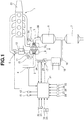
- FIG. 1 is an explanatory drawing schematically showing system of a control device for an internal combustion engine according to the present invention.
- An internal combustion engine 1 is mounted as a driving source in a vehicle such as an automobile.
- An intake passage 2 and an exhaust passage 3 are connected to the internal combustion engine 1.
- the internal combustion engine 1 is supplied with fuel by a fuel injection valve (not shown).
- the fuel injection valve is, for instance, a valve that directly injects the fuel into a cylinder (a cylinder (not shown) of the internal combustion engine 1), or might be a valve that injects the fuel into an intake port (not shown) of the internal combustion engine 1.
- the intake passage 2 is provided with an air flow meter 4 for detecting a quantity of intake air and an electrically operated throttle valve 5 for regulating the quantity of the intake air.
- the air flow meter 4 is located at an upstream side of the throttle valve 5.
- the exhaust passage 3 is provided with an upstream-side exhaust catalyst 6 such as a three-way catalyst and a downstream-side exhaust catalyst 7 such as the three-way catalyst.
- the downstream-side exhaust catalyst 7 is located at a downstream side of the upstream-side exhaust catalyst 6.
- the internal combustion engine 1 is provided with a turbo supercharger 8 as a supercharger having a compressor 9 disposed in the intake passage 2 and a turbine 10 disposed in the exhaust passage 3 with these compressor 9 and turbine 10 coaxially arranged with each other.
- the compressor 9 is positioned at an upstream side with respect to the throttle valve 5, and is positioned at a downstream side with respect to the air flow meter 4.
- the turbine 10 is positioned at an upstream side with respect to the upstream-side exhaust catalyst 6.
- an electrically operated recirculation valve 12 that controls a flow amount of intake air flowing in the recirculation passage 11 is installed.
- an intercooler 13 that cools intake air compressed (pressurized) by the compressor 9 is provided at an upstream side of the throttle valve 5 in the intake passage 2.
- An exhaust bypass passage 14 bypassing the turbine 10 and connecting an upstream side and a downstream side of the turbine 10 is connected to the exhaust passage 3.
- a downstream side end of the exhaust bypass passage 14 is connected to the exhaust passage 3 in an upstream position with respect to the upstream-side exhaust catalyst 6.
- an electrically operated waste gate valve 15 that controls a flow amount of exhaust air flowing in the exhaust bypass passage 14 is installed.
- the internal combustion engine 1 is an exhaust gas recirculation (EGR) -capable engine, and an EGR passage 16 branching off from the exhaust passage 3 and connecting to the intake passage 2 is provided.
- EGR exhaust gas recirculation
- One end of the EGR passage 16 is connected to the exhaust passage 3 between the upstream-side exhaust catalyst 6 and the downstream-side exhaust catalyst 7, and the other end of the EGR passage 16 is connected to the intake passage 2 in a downstream position of the air flow meter 4 and in an upstream position of the compressor 9.
- an electrically operated EGR valve 17 that regulates or controls a flow amount of EGR gas in the EGR passage 16 and an EGR cooler 18 that can cool the EGR gas are provided. Opening and closing operation of the EGR valve 17 is controlled by a control unit 21.
- the control unit 21 inputs a detection signal of the above-mentioned air flow meter 4, and also inputs detection signals from various sensors of a crank angle sensor 22 that detects an engine rotation speed and a crank angle position of the internal combustion engine 1, an accelerator opening degree sensor 23 that detects a depression amount (an accelerator opening degree) of an accelerator pedal operated by a driver, an EGR gas temperature sensor 24 that detects temperature of the EGR gas introduced into the intake passage 2, an EGR passage pressure sensor 25 that detects a relative pressure of front-and-back (upstream and downstream sides) of the EGR valve 17 in the EGR passage 16, an exhaust temperature sensor 26 that detects temperature of exhaust flowing into the upstream-side exhaust catalyst 6, a vehicle speed sensor 27 that detects a speed of the vehicle, an acceleration sensor 28 that detects an acceleration of the vehicle, and so on.
- a required torque of the internal combustion engine 1 is calculated using a detection value of the accelerator opening degree sensor 23.
- the control unit 21 performs controls of an ignition timing, an air-fuel ratio etc. of the internal combustion engine 1 on the basis of these detection signals .
- the control unit 21 also performs an exhaust gas recirculation control (an EGR control) that recirculates a part of the exhaust gas from the exhaust passage 3 to the intake passage 2 on the basis of the detection signals by controlling the opening degree of the EGR valve 17.
- an EGR control an exhaust gas recirculation control
- the EGR valve 17 opens when a vehicle operating condition (or a vehicle operating state) is in a predetermined operating region (an EGR region), whereas the EGR valve 17 closes when the vehicle operating condition is in a region (a non-EGR region) outside the predetermined operating region (the EGR region).
- each opening degree of the throttle valve 5, the recirculation valve 12 and the waste gate valve 15 is also controlled by the control unit 21.
- the recirculation valve 12 it is possible to use a so-called check valve that opens only when a pressure at a downstream side of the compressor 9 is a predetermined pressure or more, which is not a valve that is open-and-closure-controlled by the control unit 21.
- a driving force of the internal combustion engine 1 is transmitted to a driving wheel (not shown) of the vehicle while undergoing shift (speed change or gear change) by a manual transmission 31.
- the driver depresses a clutch pedal (not shown), then a clutch (not shown) disposed between the internal combustion engine 1 and the manual transmission 31 is disengaged. Further, the driver operates a shift lever (not shown) in a state in which the clutch is disengaged, then the driver shifts a gear to a desired shift position (or gear position).
- a series of shift operation is completed by stopping (finishing) the depression of the clutch pedal and engaging the clutch by the driver.
- the clutch pedal operation is detected by a clutch pedal switch 32.
- the clutch pedal switch 32 is a switch that outputs an ON/OFF signal according to a position of the clutch pedal. When the clutch is disengaged (when the clutch pedal is depressed), the signal is ON, whereas in a state except this ON, the signal is OFF.
- a position of the shift lever is detected by a shift position sensor 33. From this shift lever position, the shift position (a transmission ratio) of the manual transmission 31 is judged or distinguished.
- Each signal from these clutch pedal switch 32 and shift position sensor 33 is also inputted to the control unit 21.
- control unit 21 inputs signals from a vehicle-mounted car navigation system 34 and a vehicle-mounted following distance detection system 35 that detects a vehicle distance (following distance) from a vehicle ahead.
- the car navigation system 34 has a GPS receiver, and outputs information about road on which the vehicle is travelling such as a limiting speed (a regulation speed) and a gradient of the road from a current position of the vehicle and map information.
- a limiting speed a regulation speed
- a gradient of the road from a current position of the vehicle and map information.
- the following distance detection system 35 has, for instance, a millimeter wave radar or a camera etc. , and outputs a detected vehicle distance from a vehicle ahead to the control unit 21.
- a millimeter wave radar by measuring a reflected wave of a radiating radio wave, the following distance is calculated.
- the camera by analyzing information of image from the camera, the following distance is calculated.
- the control unit 21 When a predetermined fuel-cut condition is satisfied, the control unit 21 performs fuel-cut that stops fuel supply to the internal combustion engine 1.
- the fuel-cut condition is satisfied, for instance, when the engine rotation speed is equal to or higher than a predetermined fuel-cut rotation speed and the accelerator opening degree (APO) is equal to or less than a predetermined opening degree after completion of warming-up.
- the control unit 21 executes a fuel-cut control.
- the fuel-cut control of the present embodiment when the fuel-cut condition is satisfied, the fuel supply to the internal combustion engine 1 is stopped after a lapse of a predetermined fuel-cut delay time from this time point of the satisfaction of the fuel-cut condition.
- the control unit 21 resumes the fuel supply to the internal combustion engine 1.
- the fuel-cut recovery condition is satisfied, for instance, when the accelerator opening degree (APO) is larger than the predetermined opening degree, or when the engine rotation speed is equal to or less than a predetermined fuel-cut recovery rotation speed without depression of the accelerator pedal.
- APO accelerator opening degree
- the accelerator opening degree (APO) becomes the predetermined opening degree or less (fully closed) upon shifting. Because of this, the fuel-cut condition is satisfied at the time of carrying out the shift.
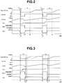
- the vehicle operating condition is in the EGR region also after time t1. That is, the vehicle operating condition at time t3 at which the fuel-cut is finished is in the EGR region.
- the EGR is forbidden until a timing of time t4 at which the inside of the exhaust passage 3 is filled with the exhaust gas.
- the EGR is forbidden until the timing of time t4 at which a predetermined time Tf elapses from time t3.
- the predetermined time Tf corresponds to a time (a time period) from resumption of the fuel supply to the internal combustion engine 1 in a state in which the inside of the exhaust passage 3 is filled with the fresh air until the exhaust passage 3 is filled with the exhaust gas.
- the fuel-cut condition is satisfied at time t1, and the fuel-cut is started at time t2 at which a first delay time T1 elapses from time t1.
- the first delay time T1 is a predetermined fuel-cut delay time.
- the gear is shifted up (upshift is carried out) during a time period from time t1 to time t3 for which the clutch is disengaged.
- the fuel-cut condition is satisfied also at time t5, and the fuel-cut is started at time t6 at which the first delay time T1 elapses from time t5. Further, in Fig.
- the gear is shifted up (upshift is carried out) during a time period from time t5 to time t7 for which the clutch is disengaged. Furthermore, although the fuel-cut is finished at time t7, the EGR is forbidden until a timing of time t8 at which the inside of the exhaust passage 3 is filled with the exhaust gas. Time t8 is a timing at which the predetermined time Tf elapses from time t7.
- the fuel efficiency improving effect by performing the EGR becomes large, and thus the fuel efficiency of the vehicle can be relatively improved by immediately performing the EGR after completion of the shift without performing the fuel-cut.
- the vehicle operating condition after the shift is predicted on the basis of the vehicle operating condition at the time of the shift. And, on the basis of the predicted vehicle operating condition after the shift, determination whether or not the fuel-cut is performed is made.
- the vehicle operating condition after the shift is predicted at a timing at which the fuel-cut condition is satisfied. Then, when it is predicted that the fuel efficiency of the case where the fuel-cut is not performed is relatively improved, the fuel-cut is not going to be performed. On the other hand, when it is predicted that the fuel efficiency of the case where the fuel-cut is performed is relatively improved, the fuel-cut is going to be performed.
- the fuel-cut upon shifting during execution of the EGR, when it is predicted that the vehicle operating condition after the shift is in the EGR region and the fuel efficiency improving effect by the EGR is relatively large, the fuel-cut is not going to be performed.
- the fuel-cut upon shifting during execution of the EGR, when it is predicted that the fuel efficiency improving effect by the EGR after the shift is relatively small, the fuel-cut is going to be performed.
- a case where it is predicted that the fuel efficiency improving effect by the EGR after the shift is relatively small is, for instance, a case where the EGR ratio is low, or a case where the vehicle operating condition is in the non-EGR region.
- Fig. 3 is a timing chart in a case where the fuel-cut is not performed upon shifting.
- a start time of the fuel-cut is delayed until time t4 at which a second delay timeT2 elapses from time t1. That is, upon shifting during execution of the EGR, when it is predicted that the vehicle operating condition after the shift is in the EGR region and the fuel efficiency of the case where the fuel-cut is not performed is relatively improved, a fuel-cut delay time from a time (time t1) of the satisfaction of the fuel-cut condition until the fuel-cut is started is delayed.
- the second delay time T2 is a fuel-cut delay time that is set to be longer than the first delay time T1 and is set to be sufficiently longer than a time required to complete the shift.
- Time t2 in Fig. 3 is a timing at which the clutch disengaged at time t1 is engaged. Then, in Fig. 3 , the gear is shifted up (upshift is carried out) during a time period from time t1 to time t2 for which the clutch is disengaged. Time t3 in Fig.
- time t3 is a timing at which the EGR is resumed by the fact that the accelerator opening degree (APO) after completion of the shift is increased and the engine load is increased then the vehicle operating condition shifts to or enters the EGR region.
- time t3 is substantially same as a timing at which the accelerator opening degree (APO) becomes stable.
- the timing at which the EGR is resumed and the timing at which the accelerator opening degree (APO) becomes stable are not always the same timing.
- the fuel-cut condition is satisfied, and it is predicted that the vehicle operating condition after the shift is in the EGR region and the fuel efficiency of the case where the fuel-cut is not performed is relatively improved.
- Fig. 3 at a timing of time t5
- a start time of the fuel-cut is delayed until time t8 at which the second delay time T2 elapses from time t5.
- the shift is completed before time t8 at which the second delay time T2 elapses from time t5, and the EGR is started at a timing of time t7 that is before time t8.
- Time t7 in Fig. 3 which is similar to time t3, is a timing at which the EGR is resumed by the fact that the accelerator opening degree (APO) after completion of the shift is increased and the engine load is increased then the vehicle operating condition shifts to or enters the EGR region.
- time t7 is substantially same as a timing at which the accelerator opening degree (APO) becomes stable.
- Time t6 in Fig. 3 is a timing at which the clutch disengaged at time t5 is engaged. Then, in Fig. 3 , the gear is shifted up (upshift is carried out) during a time period from time t5 to time t6 for which the clutch is disengaged.
- the vehicle operating condition after the shift can be predicted according to whether the vehicle accelerates by the shift, whether the vehicle decelerates by the shift and whether the vehicle speed does not change by the shift etc..
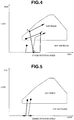
- Fig. 4 is an explanatory drawing schematically showing a change of the operating condition in a case where the vehicle accelerates by the shift (gear change) .
- An arrow represented by a solid line in Fig. 4 indicates a change of an operating point of the internal combustion engine 1 in a case where the gear is shifted up (upshift is carried out).
- An arrow represented by a broken line in Fig. 4 indicates a change of the operating point of the internal combustion engine 1 in a case where the gear is shifted down (downshift is carried out).
- the fuel-cut is not performed upon shifting so as to be able to immediately perform the EGR after completion of the shift.
- the clutch is disengaged at a point A, and the clutch is engaged in a line (or a region) from a point C to a point B.
- the engine rotation speed of the internal combustion engine 1 at the point B is lower than that at the point A.
- the load of the internal combustion engine 1 at the point B is higher than that at the point A.
- Fig. 5 is an explanatory drawing schematically showing a change of the operating state in a case where the vehicle decelerates by the shift.
- An arrow represented by a solid line in Fig. 5 indicates a change of the operating point of the internal combustion engine 1 in a case where the gear is shifted up (upshift is carried out).
- An arrow represented by a broken line in Fig. 5 indicates a change of the operating point of the internal combustion engine 1 in a case where the gear is shifted down (downshift is carried out).
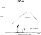
- Fig. 6 is an explanatory drawing schematically showing a change of the operating state in a case where the vehicle speed does not change by the shift.
- An arrow represented by a solid line in Fig. 6 indicates a change of the operating point of the internal combustion engine 1 in a case where the gear is shifted up (upshift is carried out).
- An arrow represented by a broken line in Fig. 6 indicates a change of the operating point of the internal combustion engine 1 in a case where the gear is shifted down (downshift is carried out).
- the upshift is carried out and the EGR ratio is such an amount as the fuel efficiency improving effect by the EGR is relatively small, it is predicted that the fuel efficiency of the case where the fuel-cut is performed upon shifting is relatively improved. Further, if the downshift is carried out, it is predicted that the fuel efficiency of the case where the fuel-cut is performed upon shifting is relatively improved.
- the fuel-cut delay time could be delayed.
- the upshift is carried out during the delay of the fuel-cut, the fuel-cut remains undone, whereas if the downshift is carried out during the delay of the fuel-cut, the fuel-cut is performed from this time point.
- the prediction of the vehicle operating condition after the shift such as acceleration and deceleration, made based on the vehicle operating condition at the time of the shift can be made from, for instance, the vehicle distance (following distance) from a vehicle ahead, information about the limiting speed (regulation speed), the gradient of the road, the vehicle speed and the engine rotation speed and the gear position (the shift position), the vehicle speed and the acceleration, a returning speed of the accelerator pedal, and so on.
- the prediction of the vehicle operating condition after the shift it could be possible to judge the vehicle operating condition by combining the following prediction methods explained below as necessary.
- the fuel-cut delay time is delayed, and if the upshift is carried out, the fuel-cut remains undone, whereas if the downshift is carried out, the fuel-cut is performed from this time point.
- the fuel-cut delay time is delayed, and if the upshift is carried out, the fuel-cut remains undone, whereas if the downshift is carried out, the fuel-cut is performed from this time point.
- the returning speed of the accelerator pedal (an acceleration returning speed) is equal to or greater than a predetermined acceleration returning speed threshold value, it is conceivable that the vehicle will accelerate by carrying out the upshift. In this case, it is predicted that the vehicle operating condition after the shift is in the EGR region. Therefore, when the returning speed of the accelerator pedal is equal to or greater than the predetermined acceleration returning speed threshold value upon shifting, since the fuel efficiency of the vehicle is relatively improved by immediately performing the EGR after the shift, the fuel-cut is not performed by delaying the fuel-cut delay time.
- the acceleration returning speed is calculated from, for instance, a displacement per unit time of a depression amount of the accelerator pedal which is detected by the accelerator opening degree sensor 23.
- Fig. 7 is a flow chart showing a flow of the control in the embodiment described above.
- the vehicle operating condition is monitored.
- a judgment is made as to whether or not a shift operation is predicted.
- the routine proceeds to step S3.
- a current routine is ended.
- step S3 a judgment is made as to whether or not the fuel efficiency improving effect by the EGR after the shift is large.
- the routine proceeds to step S4.
- step S3 if it is judged that the fuel efficiency improving effect by the EGR after the shift is relatively small, the routine proceeds to step S6.
- step S4 a judgment of the shift operation is made. That is, if the accelerator opening degree is the predetermined opening degree or less (fully closed) and the clutch is in a disengagement state, it is judged that the shift operation occurs. At step S4, if it is judged that the shift operation occurs, the routine proceeds to step S5.
- step S5 the fuel-cut delay time is delayed. That is, a fuel-cut control using the delayed fuel-cut delay time is executed.
- a normal fuel-cut control is executed. That is, if the shift operation occurs, the normal fuel-cut control is executed without delaying the fuel-cut delay time.
- the present invention can be applied to a normal aspiration (or natural aspiration) internal combustion engine having no supercharger.
- the present invention can be applied to, for instance, a so-called port injection type internal combustion engine (a port injection engine) in which fuel is injected into the intake port or a direct-injection type internal combustion engine (a direct injection engine) in which fuel is directly injected into the cylinder.
- a port injection engine a port injection engine
- a direct-injection type internal combustion engine a direct injection engine
- the embodiment described above is concerned with the control method for the internal combustion engine 1 and the control device for the internal combustion engine 1.
Landscapes
- Engineering & Computer Science (AREA)
- Chemical & Material Sciences (AREA)
- Combustion & Propulsion (AREA)
- Mechanical Engineering (AREA)
- General Engineering & Computer Science (AREA)
- Control Of Vehicle Engines Or Engines For Specific Uses (AREA)
- Electrical Control Of Air Or Fuel Supplied To Internal-Combustion Engine (AREA)
- Control Of Transmission Device (AREA)
- Combined Controls Of Internal Combustion Engines (AREA)
- Exhaust-Gas Circulating Devices (AREA)
Abstract
Description
- The present invention relates to a control method for an internal combustion engine mounted in a vehicle having a manual transmission and a control device for the internal combustion engine.
- For instance, Patent Document 1 discloses a recirculation exhaust gas amount control device for an internal combustion engine which recirculates, as EGR gas, a part of exhaust gas exhausted from a combustion chamber of the internal combustion engine, to an intake passage according to an engine operating state.
- In this Patent Document 1, a transmission is a manual transmission, and when performing fuel-cut that stops fuel supply to the internal combustion engine with an accelerator pedal released upon shifting (upon changing gear), an inside of an exhaust pipe is filled with fresh air.
- In the Patent Document 1, however, even if the fuel-cut is ended, it is impossible to recirculate the EGR gas to the intake passage until the inside of the exhaust pipe is filled with the exhaust gas. Especially in a case where the shift is frequently carried out, a state in which the EGR gas cannot be introduced into the intake passage continues for a long time. For this reason, there is a risk of not obtaining a fuel efficiency improving effect that can be obtained by introducing the EGR gas into the intake passage upon shifting during execution of EGR.
- Patent Document 1 : Japanese Patent No.
3887986 - The present invention determines, on the basis of a vehicle operating condition at a time of the shift, whether the fuel-cut that stops the fuel supply to the internal combustion engine is performed or not upon shifting during execution of the EGR that recirculates the EGR gas to the intake passage.
- If the fuel-cut is performed upon shifting, it is not possible to immediately perform the EGR at the time of ending the fuel-cut after completion of the shift. This is because an exhaust passage is filled with fresh air (air) during the fuel-cut.
- According to the present invention, it is possible to relatively improve fuel efficiency of the vehicle upon shifting during execution of the EGR.
-
-
Fig. 1 is an explanatory drawing schematically showing system of a control device for an internal combustion engine according to the present invention. -
Fig. 2 is a timing chart in a case where fuel-cut is performed upon shifting. -
Fig. 3 is a timing chart in a case where the fuel-cut is not performed upon shifting. -
Fig. 4 is an explanatory drawing schematically showing a change of an operating state (an operating condition) in a case where a vehicle accelerates by the shift (gear change). -
Fig. 5 is an explanatory drawing schematically showing a change of the operating state in a case where the vehicle decelerates by the shift. -
Fig. 6 is an explanatory drawing schematically showing a change of the operating state in a case where a vehicle speed does not change by the shift. -
Fig. 7 is a flow chart schematically showing a control method for the internal combustion engine according to the present invention. - In the following description, an embodiment of the present invention will be explained on the basis of the drawings.
Fig. 1 is an explanatory drawing schematically showing system of a control device for an internal combustion engine according to the present invention. - An internal combustion engine 1 is mounted as a driving source in a vehicle such as an automobile. An
intake passage 2 and anexhaust passage 3 are connected to the internal combustion engine 1. - The internal combustion engine 1 is supplied with fuel by a fuel injection valve (not shown). The fuel injection valve is, for instance, a valve that directly injects the fuel into a cylinder (a cylinder (not shown) of the internal combustion engine 1), or might be a valve that injects the fuel into an intake port (not shown) of the internal combustion engine 1.
- The
intake passage 2 is provided with anair flow meter 4 for detecting a quantity of intake air and an electrically operatedthrottle valve 5 for regulating the quantity of the intake air. Theair flow meter 4 is located at an upstream side of thethrottle valve 5. - The
exhaust passage 3 is provided with an upstream-side exhaust catalyst 6 such as a three-way catalyst and a downstream-side exhaust catalyst 7 such as the three-way catalyst. The downstream-side exhaust catalyst 7 is located at a downstream side of the upstream-side exhaust catalyst 6. - Further, the internal combustion engine 1 is provided with a
turbo supercharger 8 as a supercharger having acompressor 9 disposed in theintake passage 2 and aturbine 10 disposed in theexhaust passage 3 with thesecompressor 9 andturbine 10 coaxially arranged with each other. Thecompressor 9 is positioned at an upstream side with respect to thethrottle valve 5, and is positioned at a downstream side with respect to theair flow meter 4. Theturbine 10 is positioned at an upstream side with respect to the upstream-side exhaust catalyst 6. - A
recirculation passage 11 bypassing thecompressor 9 and connecting an upstream side and a downstream side of thecompressor 9 is connected to theintake passage 2. In therecirculation passage 11, an electrically operatedrecirculation valve 12 that controls a flow amount of intake air flowing in therecirculation passage 11 is installed. - In addition, an
intercooler 13 that cools intake air compressed (pressurized) by thecompressor 9 is provided at an upstream side of thethrottle valve 5 in theintake passage 2. - An
exhaust bypass passage 14 bypassing theturbine 10 and connecting an upstream side and a downstream side of theturbine 10 is connected to theexhaust passage 3. A downstream side end of theexhaust bypass passage 14 is connected to theexhaust passage 3 in an upstream position with respect to the upstream-side exhaust catalyst 6. In theexhaust bypass passage 14, an electrically operatedwaste gate valve 15 that controls a flow amount of exhaust air flowing in theexhaust bypass passage 14 is installed. - The internal combustion engine 1 is an exhaust gas recirculation (EGR) -capable engine, and an
EGR passage 16 branching off from theexhaust passage 3 and connecting to theintake passage 2 is provided. One end of the EGRpassage 16 is connected to theexhaust passage 3 between the upstream-side exhaust catalyst 6 and the downstream-side exhaust catalyst 7, and the other end of theEGR passage 16 is connected to theintake passage 2 in a downstream position of theair flow meter 4 and in an upstream position of thecompressor 9. In thisEGR passage 16, an electrically operatedEGR valve 17 that regulates or controls a flow amount of EGR gas in theEGR passage 16 and anEGR cooler 18 that can cool the EGR gas are provided. Opening and closing operation of theEGR valve 17 is controlled by acontrol unit 21. - The
control unit 21 inputs a detection signal of the above-mentionedair flow meter 4, and also inputs detection signals from various sensors of acrank angle sensor 22 that detects an engine rotation speed and a crank angle position of the internal combustion engine 1, an acceleratoropening degree sensor 23 that detects a depression amount (an accelerator opening degree) of an accelerator pedal operated by a driver, an EGRgas temperature sensor 24 that detects temperature of the EGR gas introduced into theintake passage 2, an EGRpassage pressure sensor 25 that detects a relative pressure of front-and-back (upstream and downstream sides) of theEGR valve 17 in theEGR passage 16, anexhaust temperature sensor 26 that detects temperature of exhaust flowing into the upstream-side exhaust catalyst 6, avehicle speed sensor 27 that detects a speed of the vehicle, anacceleration sensor 28 that detects an acceleration of the vehicle, and so on. A required torque of the internal combustion engine 1 is calculated using a detection value of the acceleratoropening degree sensor 23. - The
control unit 21 performs controls of an ignition timing, an air-fuel ratio etc. of the internal combustion engine 1 on the basis of these detection signals . Thecontrol unit 21 also performs an exhaust gas recirculation control (an EGR control) that recirculates a part of the exhaust gas from theexhaust passage 3 to theintake passage 2 on the basis of the detection signals by controlling the opening degree of theEGR valve 17. With this EGR control, theEGR valve 17 opens when a vehicle operating condition (or a vehicle operating state) is in a predetermined operating region (an EGR region), whereas theEGR valve 17 closes when the vehicle operating condition is in a region (a non-EGR region) outside the predetermined operating region (the EGR region). - Here, each opening degree of the
throttle valve 5, therecirculation valve 12 and thewaste gate valve 15 is also controlled by thecontrol unit 21. As therecirculation valve 12, it is possible to use a so-called check valve that opens only when a pressure at a downstream side of thecompressor 9 is a predetermined pressure or more, which is not a valve that is open-and-closure-controlled by thecontrol unit 21. - A driving force of the internal combustion engine 1 is transmitted to a driving wheel (not shown) of the vehicle while undergoing shift (speed change or gear change) by a
manual transmission 31. When carrying out the shift by themanual transmission 31, the driver depresses a clutch pedal (not shown), then a clutch (not shown) disposed between the internal combustion engine 1 and themanual transmission 31 is disengaged. Further, the driver operates a shift lever (not shown) in a state in which the clutch is disengaged, then the driver shifts a gear to a desired shift position (or gear position). A series of shift operation is completed by stopping (finishing) the depression of the clutch pedal and engaging the clutch by the driver. - The clutch pedal operation is detected by a clutch pedal switch 32. The clutch pedal switch 32 is a switch that outputs an ON/OFF signal according to a position of the clutch pedal. When the clutch is disengaged (when the clutch pedal is depressed), the signal is ON, whereas in a state except this ON, the signal is OFF.
- A position of the shift lever is detected by a shift position sensor 33. From this shift lever position, the shift position (a transmission ratio) of the
manual transmission 31 is judged or distinguished. - Each signal from these clutch pedal switch 32 and shift position sensor 33 is also inputted to the
control unit 21. - Further, the
control unit 21 inputs signals from a vehicle-mountedcar navigation system 34 and a vehicle-mounted followingdistance detection system 35 that detects a vehicle distance (following distance) from a vehicle ahead. - The
car navigation system 34 has a GPS receiver, and outputs information about road on which the vehicle is travelling such as a limiting speed (a regulation speed) and a gradient of the road from a current position of the vehicle and map information. - The following
distance detection system 35 has, for instance, a millimeter wave radar or a camera etc. , and outputs a detected vehicle distance from a vehicle ahead to thecontrol unit 21. In a case of the radar, by measuring a reflected wave of a radiating radio wave, the following distance is calculated. In a case of the camera, by analyzing information of image from the camera, the following distance is calculated. - When a predetermined fuel-cut condition is satisfied, the
control unit 21 performs fuel-cut that stops fuel supply to the internal combustion engine 1. The fuel-cut condition is satisfied, for instance, when the engine rotation speed is equal to or higher than a predetermined fuel-cut rotation speed and the accelerator opening degree (APO) is equal to or less than a predetermined opening degree after completion of warming-up. When the fuel-cut condition is satisfied, thecontrol unit 21 executes a fuel-cut control. In the fuel-cut control of the present embodiment, when the fuel-cut condition is satisfied, the fuel supply to the internal combustion engine 1 is stopped after a lapse of a predetermined fuel-cut delay time from this time point of the satisfaction of the fuel-cut condition. - Then, when a predetermined fuel-cut recovery condition is satisfied during the fuel-cut, the
control unit 21 resumes the fuel supply to the internal combustion engine 1. The fuel-cut recovery condition is satisfied, for instance, when the accelerator opening degree (APO) is larger than the predetermined opening degree, or when the engine rotation speed is equal to or less than a predetermined fuel-cut recovery rotation speed without depression of the accelerator pedal. - In the present embodiment described above, since the transmission is the
manual transmission 31, the accelerator opening degree (APO) becomes the predetermined opening degree or less (fully closed) upon shifting. Because of this, the fuel-cut condition is satisfied at the time of carrying out the shift. - Here, in a case where the shift is carried out during execution of the EGR, when the fuel-cut is performed upon shifting, an inside of the
exhaust passage 3 at the time of finishing the fuel-cut is filled with fresh air. Therefore, as shown inFig. 2 , even if the vehicle operating condition is in the EGR region, which can perform the EGR, at the time of finishing the fuel-cut immediately after completion of the shift, it is not possible to immediately resume the EGR. - In
Fig. 2 , the vehicle operating condition is in the EGR region also after time t1. That is, the vehicle operating condition at time t3 at which the fuel-cut is finished is in the EGR region. However, inFig. 2 , even though the fuel-cut is finished, the EGR is forbidden until a timing of time t4 at which the inside of theexhaust passage 3 is filled with the exhaust gas. In other words, inFig. 2 , even if the fuel-cut is finished, the EGR is forbidden until the timing of time t4 at which a predetermined time Tf elapses from time t3. The predetermined time Tf corresponds to a time (a time period) from resumption of the fuel supply to the internal combustion engine 1 in a state in which the inside of theexhaust passage 3 is filled with the fresh air until theexhaust passage 3 is filled with the exhaust gas. - Here, in
Fig. 2 , the fuel-cut condition is satisfied at time t1, and the fuel-cut is started at time t2 at which a first delay time T1 elapses from time t1. The first delay time T1 is a predetermined fuel-cut delay time. Further, inFig. 2 , the gear is shifted up (upshift is carried out) during a time period from time t1 to time t3 for which the clutch is disengaged. Furthermore, inFig. 2 , the fuel-cut condition is satisfied also at time t5, and the fuel-cut is started at time t6 at which the first delay time T1 elapses from time t5. Further, inFig. 2 , the gear is shifted up (upshift is carried out) during a time period from time t5 to time t7 for which the clutch is disengaged. Furthermore, although the fuel-cut is finished at time t7, the EGR is forbidden until a timing of time t8 at which the inside of theexhaust passage 3 is filled with the exhaust gas. Time t8 is a timing at which the predetermined time Tf elapses from time t7. - Here, in a case where the fuel-cut is performed upon shifting, a fuel efficiency improving effect by the fuel-cut during the shift can be obtained. However, due to the fact that the EGR cannot be performed until the
exhaust passage 3 is filled with the exhaust gas after finish of the fuel-cut, a fuel efficiency after completion of the shift might be relatively deteriorated or decreased as compared with a case where the EGR is immediately performed after completion of the shift without performing the fuel-cut upon shifting. Further, in a case where the fuel-cut is not performed upon shifting, although the fuel efficiency improving effect by the fuel-cut during the shift cannot be obtained, it is possible to immediately perform the EGR at a time when the shift is completed, and the fuel efficiency after completion of the shift might be relatively improved or increased as compared with a case where the fuel-cut is performed upon shifting. - For instance, when carrying out the shift during execution of the EGR, if the vehicle operating condition after the shift continues being in the EGR region and an EGR ratio is large, the fuel-cut is not performed upon shifting and the EGR is immediately performed after completion of the shift, which brings about relatively greater improvement in the fuel efficiency of the vehicle. That is, in the shift during execution of the EGR, there is a case where the fuel efficiency improving effect by the EGR after the shift is relatively larger than the fuel efficiency improving effect by the fuel-cut during the shift.
- Further, in a situation where the vehicle accelerates by the shift, the fuel efficiency improving effect by performing the EGR becomes large, and thus the fuel efficiency of the vehicle can be relatively improved by immediately performing the EGR after completion of the shift without performing the fuel-cut.
- Therefore, it is important, upon shifting, to ascertain the vehicle operating condition after the shift. That is, it is important, upon shifting, to predict whether the fuel efficiency improving effect by immediately performing the EGR after the shift is large or not.
- Thus, in the present embodiment, upon shifting during execution of the EGR, the vehicle operating condition after the shift is predicted on the basis of the vehicle operating condition at the time of the shift. And, on the basis of the predicted vehicle operating condition after the shift, determination whether or not the fuel-cut is performed is made.
- That is, in the present embodiment, upon shifting during execution of the EGR, the vehicle operating condition after the shift is predicted at a timing at which the fuel-cut condition is satisfied. Then, when it is predicted that the fuel efficiency of the case where the fuel-cut is not performed is relatively improved, the fuel-cut is not going to be performed. On the other hand, when it is predicted that the fuel efficiency of the case where the fuel-cut is performed is relatively improved, the fuel-cut is going to be performed.
- In other words, in the present embodiment, upon shifting during execution of the EGR, when it is predicted that the vehicle operating condition after the shift is in the EGR region and the fuel efficiency improving effect by the EGR is relatively large, the fuel-cut is not going to be performed. On the other hand, upon shifting during execution of the EGR, when it is predicted that the fuel efficiency improving effect by the EGR after the shift is relatively small, the fuel-cut is going to be performed. A case where it is predicted that the fuel efficiency improving effect by the EGR after the shift is relatively small is, for instance, a case where the EGR ratio is low, or a case where the vehicle operating condition is in the non-EGR region.
- With this control, it is possible to relatively improve the fuel efficiency of the vehicle upon shifting during execution of the EGR.
-
Fig. 3 is a timing chart in a case where the fuel-cut is not performed upon shifting. - At a timing of time t1 at which the fuel-cut condition is satisfied, it is predicted that the fuel efficiency of the case where the fuel-cut is not performed is relatively improved. Therefore, a start time of the fuel-cut is delayed until time t4 at which a second delay timeT2 elapses from time t1. That is, upon shifting during execution of the EGR, when it is predicted that the vehicle operating condition after the shift is in the EGR region and the fuel efficiency of the case where the fuel-cut is not performed is relatively improved, a fuel-cut delay time from a time (time t1) of the satisfaction of the fuel-cut condition until the fuel-cut is started is delayed. The second delay time T2 is a fuel-cut delay time that is set to be longer than the first delay time T1 and is set to be sufficiently longer than a time required to complete the shift.
- Then, in
Fig. 3 , the shift is completed before time t4 at which the second delay time T2 elapses from time t1, and the EGR is started at a timing of time t3 that is before time t4. InFig. 3 , since theexhaust passage 3 is filled with the exhaust gas at a time point of time t3, as shown by a broken line inFig. 3 , there is no need to delay the EGR after completion of the shift. - Here, in
Fig. 3 , since the accelerator opening degree APO is the predetermined opening degree or less (fully closed) by and according to disengagement of the clutch at time t1 and an engine load (a load of the internal combustion engine 1) is decreased, the vehicle operating condition shifts to or enters the non-EGR region. Time t2 inFig. 3 is a timing at which the clutch disengaged at time t1 is engaged. Then, inFig. 3 , the gear is shifted up (upshift is carried out) during a time period from time t1 to time t2 for which the clutch is disengaged. Time t3 inFig. 3 is a timing at which the EGR is resumed by the fact that the accelerator opening degree (APO) after completion of the shift is increased and the engine load is increased then the vehicle operating condition shifts to or enters the EGR region. And, time t3 is substantially same as a timing at which the accelerator opening degree (APO) becomes stable. Here, the timing at which the EGR is resumed and the timing at which the accelerator opening degree (APO) becomes stable are not always the same timing. Further, inFig. 3 , at a timing of time t5, the fuel-cut condition is satisfied, and it is predicted that the vehicle operating condition after the shift is in the EGR region and the fuel efficiency of the case where the fuel-cut is not performed is relatively improved. Furthermore, inFig. 3 , a start time of the fuel-cut is delayed until time t8 at which the second delay time T2 elapses from time t5. InFig. 3 , the shift is completed before time t8 at which the second delay time T2 elapses from time t5, and the EGR is started at a timing of time t7 that is before time t8. Time t7 inFig. 3 , which is similar to time t3, is a timing at which the EGR is resumed by the fact that the accelerator opening degree (APO) after completion of the shift is increased and the engine load is increased then the vehicle operating condition shifts to or enters the EGR region. And, time t7 is substantially same as a timing at which the accelerator opening degree (APO) becomes stable. Here, the timing at which the EGR is resumed and the timing at which the accelerator opening degree (APO) becomes stable are not always the same timing. Time t6 inFig. 3 is a timing at which the clutch disengaged at time t5 is engaged. Then, inFig. 3 , the gear is shifted up (upshift is carried out) during a time period from time t5 to time t6 for which the clutch is disengaged. - The vehicle operating condition after the shift can be predicted according to whether the vehicle accelerates by the shift, whether the vehicle decelerates by the shift and whether the vehicle speed does not change by the shift etc..
-
Fig. 4 is an explanatory drawing schematically showing a change of the operating condition in a case where the vehicle accelerates by the shift (gear change) . An arrow represented by a solid line inFig. 4 indicates a change of an operating point of the internal combustion engine 1 in a case where the gear is shifted up (upshift is carried out). An arrow represented by a broken line inFig. 4 indicates a change of the operating point of the internal combustion engine 1 in a case where the gear is shifted down (downshift is carried out). - As shown in
Fig. 4 , in a case where the load of the internal combustion engine 1 is increased by the fact that the vehicle accelerates by the shift etc., even if the upshift is carried out or the downshift is carried out, there is a strong possibility that the vehicle operating condition after the shift will be in the EGR region. Therefore, it is predicted that the fuel efficiency of the case where the fuel-cut is not performed upon shifting is relatively improved. - Thus, when it is predicted that the load of the internal combustion engine 1 is increased in the shift during execution of the EGR, the fuel-cut is not performed upon shifting so as to be able to immediately perform the EGR after completion of the shift.
- Here, regarding the arrow represented by the solid line in
Fig. 4 , the clutch is disengaged at a point A, and the clutch is engaged in a line (or a region) from a point C to a point B. The engine rotation speed of the internal combustion engine 1 at the point B is lower than that at the point A. The load of the internal combustion engine 1 at the point B is higher than that at the point A. -
Fig. 5 is an explanatory drawing schematically showing a change of the operating state in a case where the vehicle decelerates by the shift. An arrow represented by a solid line inFig. 5 indicates a change of the operating point of the internal combustion engine 1 in a case where the gear is shifted up (upshift is carried out). An arrow represented by a broken line inFig. 5 indicates a change of the operating point of the internal combustion engine 1 in a case where the gear is shifted down (downshift is carried out). - As shown in
Fig. 5 , in a case where the load of the internal combustion engine 1 is decreased by the fact that the vehicle decelerates by the shift etc., even if the upshift is carried out or the downshift is carried out, there is a strong possibility that the vehicle operating condition after the shift will be in the non-EGR region. Therefore, it is predicted that the fuel efficiency of the case where the fuel-cut is performed upon shifting is relatively improved. - Thus, when it is predicted that the load of the internal combustion engine 1 is decreased in the shift during execution of the EGR, since there is no need to immediately perform the EGR after completion of the shift, the fuel-cut is performed upon shifting.
-
Fig. 6 is an explanatory drawing schematically showing a change of the operating state in a case where the vehicle speed does not change by the shift. An arrow represented by a solid line inFig. 6 indicates a change of the operating point of the internal combustion engine 1 in a case where the gear is shifted up (upshift is carried out). An arrow represented by a broken line inFig. 6 indicates a change of the operating point of the internal combustion engine 1 in a case where the gear is shifted down (downshift is carried out). - As shown in
Fig. 6 , in a case where the vehicle speed does not change by the shift, if the upshift is carried out, the load of the internal combustion engine 1 is increased and the vehicle operating condition after the shift is in the EGR region, whereas if the downshift is carried out, the load of the internal combustion engine 1 is decreased and the vehicle operating condition after the shift is in the non-EGR region. That is, if the upshift is carried out and the EGR ratio is such an amount as the fuel efficiency improving effect by the EGR is relatively large, it is predicted that the fuel efficiency of the case where the fuel-cut is not performed upon shifting is relatively improved. On the other hand, if the upshift is carried out and the EGR ratio is such an amount as the fuel efficiency improving effect by the EGR is relatively small, it is predicted that the fuel efficiency of the case where the fuel-cut is performed upon shifting is relatively improved. Further, if the downshift is carried out, it is predicted that the fuel efficiency of the case where the fuel-cut is performed upon shifting is relatively improved. - Thus, when it is predicted that the vehicle speed does not change in the shift during execution of the EGR, if it is predicted that the upshift is carried out and if the EGR ratio is such an amount as the fuel efficiency improving effect by the EGR is relatively large, the fuel-cut is not performed upon shifting so as to be able to immediately perform the EGR after completion of the shift.
- When it is predicted that the vehicle speed does not change in the shift during execution of the EGR, if it is predicted that the upshift is carried out and if the EGR ratio is such an amount as the fuel efficiency improving effect by the EGR is relatively small, since there is no need to immediately perform the EGR after completion of the shift, the fuel-cut is performed upon shifting.
- Further, when it is predicted that the vehicle speed does not change in the shift during execution of the EGR, if it is predicted that the downshift is carried out, since there is no need to immediately perform the EGR after completion of the shift, the fuel-cut is performed upon shifting.
- Here, when, although it is predicted that the vehicle speed does not change by the shift, it is not possible to predict whether the shift is the upshift or the downshift at a timing at which the fuel-cut condition is satisfied, for instance, the fuel-cut delay time could be delayed. In this case, for instance, if the upshift is carried out during the delay of the fuel-cut, the fuel-cut remains undone, whereas if the downshift is carried out during the delay of the fuel-cut, the fuel-cut is performed from this time point.
- The prediction of the vehicle operating condition after the shift, such as acceleration and deceleration, made based on the vehicle operating condition at the time of the shift can be made from, for instance, the vehicle distance (following distance) from a vehicle ahead, information about the limiting speed (regulation speed), the gradient of the road, the vehicle speed and the engine rotation speed and the gear position (the shift position), the vehicle speed and the acceleration, a returning speed of the accelerator pedal, and so on. Here, regarding the prediction of the vehicle operating condition after the shift, it could be possible to judge the vehicle operating condition by combining the following prediction methods explained below as necessary.
- When carrying out the shift, if the following distance from a vehicle ahead is increased, it is conceivable that the vehicle will accelerate by carrying out the upshift in order to decrease (narrow) the following distance. In this case, it is predicted that the vehicle operating condition after the shift is in the EGR region. Therefore, when the following distance from a vehicle ahead is increased upon shifting, since the fuel efficiency of the vehicle is relatively improved by immediately performing the EGR after the shift, the fuel-cut is not performed by delaying the fuel-cut delay time.
- When carrying out the shift, if the following distance from a vehicle ahead is decreased (narrowed), it is conceivable that the vehicle will decelerate by carrying out the downshift in order to increase the following distance. In this case, it is predicted that the vehicle operating condition after the shift is in the non-EGR region. Therefore, when the following distance from a vehicle ahead is decreased upon shifting, since the fuel efficiency of the vehicle is relatively improved by performing the fuel-cut, the fuel-cut is performed without delaying the fuel-cut delay time.
- When carrying out the shift, if the following distance from a vehicle ahead is constant, it is conceivable that the vehicle speed will not change before and after the shift. In this case, for instance, the fuel-cut delay time is delayed, and if the upshift is carried out, the fuel-cut remains undone, whereas if the downshift is carried out, the fuel-cut is performed from this time point.
- When carrying out the shift, if the vehicle speed is less than the limiting speed, it is conceivable that the vehicle will accelerate by carrying out the upshift in order to increase the vehicle speed. In this case, it is predicted that the vehicle operating condition after the shift is in the EGR region. Therefore, when the vehicle speed is less than the limiting speed upon shifting, since the fuel efficiency of the vehicle is relatively improved by immediately performing the EGR after the shift, the fuel-cut is not performed by delaying the fuel-cut delay time.
- When carrying out the shift, if the vehicle speed exceeds the limiting speed, it is conceivable that the vehicle will decelerate by carrying out the downshift in order to decrease the vehicle speed. In this case, it is predicted that the vehicle operating condition after the shift is in the non-EGR region. Therefore, when the vehicle speed exceeds the limiting speed upon shifting, since the fuel efficiency of the vehicle is relatively improved by performing the fuel-cut, the fuel-cut is performed without delaying the fuel-cut delay time.
- When carrying out the shift, if the vehicle speed is the limiting speed, it is conceivable that the vehicle speed will not change before and after the shift. In this case, for instance, the fuel-cut delay time is delayed, and if the upshift is carried out, the fuel-cut remains undone, whereas if the downshift is carried out, the fuel-cut is performed from this time point.
- When carrying out the shift, if the road is an upward slope, it is conceivable that the vehicle will accelerate by carrying out the downshift. In this case, it is predicted that the vehicle operating condition after the shift is in the EGR region. In this case, although the fuel efficiency improving effect by the EGR, which is equal to that of the case where the vehicle accelerates by carrying out the upshift, cannot be obtained, the fuel efficiency improving effect is larger than that of the case where the fuel-cut is performed. Therefore, when the road is the upward slope upon shifting, since the fuel efficiency of the vehicle is relatively improved by immediately performing the EGR after the shift, the fuel-cut is not performed by delaying the fuel-cut delay time.
- When carrying out the shift, if the road is a downward slope, it is conceivable that the vehicle will decelerate by carrying out the downshift. In this case, it is predicted that the vehicle operating condition after the shift is in the non-EGR region. Therefore, when the road is the downward slope upon shifting, since the fuel efficiency of the vehicle is relatively improved by performing the fuel-cut, the fuel-cut is performed without delaying the fuel-cut delay time.
- When carrying out the shift, if the engine rotation speed is high relative to (or with respect to) the vehicle speed, it is conceivable that the vehicle will accelerate by carrying out the upshift. In this case, it is predicted that the vehicle operating condition after the shift is in the EGR region. Therefore, when the engine rotation speed is high relative to (or with respect to) the vehicle speed upon shifting, since the fuel efficiency of the vehicle is relatively improved by immediately performing the EGR after the shift, the fuel-cut is not performed by delaying the fuel-cut delay time.
- When carrying out the shift, if the engine rotation speed is low relative to (or with respect to) the vehicle speed, it is conceivable that the vehicle will decelerate by carrying out the downshift. In this case, it is predicted that the vehicle operating condition after the shift is in the non-EGR region. Therefore, when the engine rotation speed is low relative to (or with respect to) the vehicle speed upon shifting, since the fuel efficiency of the vehicle is relatively improved by performing the fuel-cut, the fuel-cut is performed without delaying the fuel-cut delay time.
- When carrying out the shift, if an acceleration of the vehicle is equal to or greater than a predetermined acceleration threshold value that is previously set on the basis of the vehicle speed, it is conceivable that the acceleration will continue by the shift. In this case, it is predicted that the vehicle operating condition after the shift is in the EGR region. Therefore, when the acceleration of the vehicle is equal to or greater than the predetermined acceleration threshold value upon shifting, since the fuel efficiency of the vehicle is relatively improved by immediately performing the EGR after the shift, the fuel-cut is not performed by delaying the fuel-cut delay time.
- When carrying out the shift, if the returning speed of the accelerator pedal (an acceleration returning speed) is equal to or greater than a predetermined acceleration returning speed threshold value, it is conceivable that the vehicle will accelerate by carrying out the upshift. In this case, it is predicted that the vehicle operating condition after the shift is in the EGR region. Therefore, when the returning speed of the accelerator pedal is equal to or greater than the predetermined acceleration returning speed threshold value upon shifting, since the fuel efficiency of the vehicle is relatively improved by immediately performing the EGR after the shift, the fuel-cut is not performed by delaying the fuel-cut delay time. The acceleration returning speed is calculated from, for instance, a displacement per unit time of a depression amount of the accelerator pedal which is detected by the accelerator
opening degree sensor 23. -
Fig. 7 is a flow chart showing a flow of the control in the embodiment described above. At step S1, the vehicle operating condition is monitored. At step S2, a judgment is made as to whether or not a shift operation is predicted. At step S2, for instance, if the accelerator opening degree is the predetermined opening degree or less (fully closed), the shift operation is predicted, then the routine proceeds to step S3. At step S2, if the shift operation is not predicted, a current routine is ended. - At step S3, a judgment is made as to whether or not the fuel efficiency improving effect by the EGR after the shift is large. At step S3, if it is judged that the fuel efficiency improving effect by the EGR after the shift is relatively large, the routine proceeds to step S4. At step S3, if it is judged that the fuel efficiency improving effect by the EGR after the shift is relatively small, the routine proceeds to step S6.
- At step S4, a judgment of the shift operation is made. That is, if the accelerator opening degree is the predetermined opening degree or less (fully closed) and the clutch is in a disengagement state, it is judged that the shift operation occurs. At step S4, if it is judged that the shift operation occurs, the routine proceeds to step S5.
- At step S5, the fuel-cut delay time is delayed. That is, a fuel-cut control using the delayed fuel-cut delay time is executed.
- At step S6, a normal fuel-cut control is executed. That is, if the shift operation occurs, the normal fuel-cut control is executed without delaying the fuel-cut delay time.
- Here, upon shifting during execution of the EGR, even if the vehicle operating condition after the shift is in the EGR region, when it is predicted that the fuel efficiency of the case where the fuel-cut is performed is relatively improved, the fuel-cut could be performed.
- Although the internal combustion engine 1 of the embodiment described above is provided with the supercharger, the present invention can be applied to a normal aspiration (or natural aspiration) internal combustion engine having no supercharger.
- The present invention can be applied to, for instance, a so-called port injection type internal combustion engine (a port injection engine) in which fuel is injected into the intake port or a direct-injection type internal combustion engine (a direct injection engine) in which fuel is directly injected into the cylinder.
- Further, the embodiment described above is concerned with the control method for the internal combustion engine 1 and the control device for the internal combustion engine 1.
Claims (10)
- A method for controlling an internal combustion engine provided with a manual transmission that transmits a driving force of the internal combustion engine to a driving wheel of a vehicle while performing shift, an EGR passage that recirculates, as EGR gas, apart of exhaust gas from an exhaust passage to an intake passage and an EGR valve that controls a flow amount of the EGR gas, the method comprising:
upon shifting during execution of EGR that recirculates the EGR gas to the intake passage, determining, on the basis of a vehicle operating condition at a time of the shift, whether fuel-cut that stops fuel supply to the internal combustion engine is performed or not. - The method for controlling the internal combustion engine as claimed in claim 1, wherein:
when it is predicted, on the basis of a vehicle operating condition after the shift which is predicted from the vehicle operating condition at the time of the shift, that fuel efficiency of a case where the fuel-cut is not performed upon shifting is relatively more improved than fuel efficiency of a case where the fuel-cut is performed upon shifting, the fuel-cut is not going to be performed. - The method for controlling the internal combustion engine as claimed in claim 1 or 2, wherein:
upon shifting during execution of the EGR, when it is predicted that the vehicle operating condition after the shift is in an EGR region in which the EGR is performed and the fuel efficiency of the case where the fuel-cut is not performed is relatively more improved than the fuel efficiency of the case where the fuel-cut is performed, the fuel-cut is not going to be performed. - The method for controlling the internal combustion engine as claimed in any one of the preceding claims 1 to 3, wherein:
upon shifting during execution of the EGR, when it is predicted that the vehicle operating condition after the shift is in a non-EGR region in which the EGR is not performed, the fuel-cut is going to be performed. - The method for controlling the internal combustion engine as claimed in any one of the preceding claims 1 to 4, wherein:
upon shifting during execution of the EGR, when it is predicted that the vehicle operating condition after the shift is in the EGR region in which the EGR is performed and the fuel efficiency of the case where the fuel-cut is performed is relatively improved, the fuel-cut is going to be performed. - The method for controlling the internal combustion engine as claimed in claim 1 or 2, wherein:
when it is predicted that the vehicle accelerates by the shift during execution of the EGR, the fuel-cut is not going to be performed. - The method for controlling the internal combustion engine as claimed in any one of the preceding claims 1, 2 and 6, wherein:
when it is predicted that the vehicle decelerates by the shift during execution of the EGR, the fuel-cut is going to be performed. - The method for controlling the internal combustion engine as claimed in any one of the preceding claims 1, 2, 6 and 7, wherein:
when it is predicted that upshift is carried out by the shift during execution of the EGR and a vehicle speed does not change, the fuel-cut is not going to be performed. - The method for controlling the internal combustion engine as claimed in any one of the preceding claims 1, 2, 6, 7 and 8, wherein:
when it is predicted that downshift is carried out by the shift during execution of the EGR and the vehicle speed does not change, the fuel-cut is going to be performed. - A control device for an internal combustion engine comprising:a manual transmission transmitting a driving force of the internal combustion engine to a driving wheel of a vehicle while performing shift;an EGR passage recirculating, as EGR gas, a part of exhaust gas from an exhaust passage to an intake passage;an EGR valve controlling a flow amount of the EGR gas; anda control unit configured to, upon shifting during execution of EGR that recirculates the EGR gas to the intake passage, determine, on the basis of a vehicle operating condition at a time of the shift, whether fuel-cut that stops fuel supply to the internal combustion engine is performed or not.
Applications Claiming Priority (1)
| Application Number | Priority Date | Filing Date | Title |
|---|---|---|---|
| PCT/JP2016/075770 WO2018042613A1 (en) | 2016-09-02 | 2016-09-02 | Control method for internal combustion engine and control device for internal combustion engine |
Publications (3)
| Publication Number | Publication Date |
|---|---|
| EP3508712A1 true EP3508712A1 (en) | 2019-07-10 |
| EP3508712A4 EP3508712A4 (en) | 2019-09-18 |
| EP3508712B1 EP3508712B1 (en) | 2020-08-19 |
Family
ID=61300506
Family Applications (1)
| Application Number | Title | Priority Date | Filing Date |
|---|---|---|---|
| EP16915173.5A Active EP3508712B1 (en) | 2016-09-02 | 2016-09-02 | Control method for internal combustion engine and control device for internal combustion engine |
Country Status (5)
| Country | Link |
|---|---|
| EP (1) | EP3508712B1 (en) |
| JP (1) | JP6565108B2 (en) |
| CN (1) | CN109690056B (en) |
| MX (1) | MX370258B (en) |
| WO (1) | WO2018042613A1 (en) |
Family Cites Families (10)
| Publication number | Priority date | Publication date | Assignee | Title |
|---|---|---|---|---|
| JPS6027757A (en) * | 1983-07-25 | 1985-02-12 | Toyota Motor Corp | Fuel cut controlling method for electronically controlled fuel injection type internal- combustion engine for vehicle |
| JP3201153B2 (en) * | 1994-06-27 | 2001-08-20 | トヨタ自動車株式会社 | Fuel supply control device for vehicles with automatic transmission |
| JP4274266B2 (en) * | 2007-05-08 | 2009-06-03 | トヨタ自動車株式会社 | Vehicle and control method thereof |
| US8214127B2 (en) * | 2008-10-01 | 2012-07-03 | GM Global Technology Operations LLC | Torque based clutch fuel cut off |
| JP4687793B2 (en) * | 2009-01-14 | 2011-05-25 | トヨタ自動車株式会社 | Exhaust gas recirculation device |
| JP5370426B2 (en) * | 2011-07-22 | 2013-12-18 | マツダ株式会社 | Diesel engine control device |
| JP5948770B2 (en) * | 2011-09-14 | 2016-07-06 | 日産自動車株式会社 | Vehicle drive device |
| JP5849635B2 (en) * | 2011-11-16 | 2016-01-27 | マツダ株式会社 | Diesel engine control device |
| US9404468B2 (en) * | 2013-08-16 | 2016-08-02 | Ford Global Technologies, Llc | Method and system for torque control |
| US9988994B2 (en) * | 2014-06-06 | 2018-06-05 | Ford Global Technologies, Llc | Systems and methods for EGR control |
-
2016
- 2016-09-02 EP EP16915173.5A patent/EP3508712B1/en active Active
- 2016-09-02 JP JP2018536633A patent/JP6565108B2/en not_active Expired - Fee Related
- 2016-09-02 WO PCT/JP2016/075770 patent/WO2018042613A1/en not_active Ceased
- 2016-09-02 CN CN201680088880.XA patent/CN109690056B/en active Active
- 2016-09-02 MX MX2019002089A patent/MX370258B/en active IP Right Grant
Also Published As
| Publication number | Publication date |
|---|---|
| WO2018042613A1 (en) | 2018-03-08 |
| MX370258B (en) | 2019-12-09 |
| CN109690056A (en) | 2019-04-26 |
| CN109690056B (en) | 2020-04-21 |
| EP3508712A4 (en) | 2019-09-18 |
| EP3508712B1 (en) | 2020-08-19 |
| MX2019002089A (en) | 2019-06-03 |
| JPWO2018042613A1 (en) | 2019-02-21 |
| JP6565108B2 (en) | 2019-08-28 |
Similar Documents
| Publication | Publication Date | Title |
|---|---|---|
| EP2881570B1 (en) | Control device for internal combustion engine | |
| RU2689256C2 (en) | System (embodiments) and method for regenerating petrol particulate filter | |
| US8051834B2 (en) | Method for controlling the EGR and the throttle valves in an internal combustion engine | |
| JP6413964B2 (en) | Cruise control equipment | |
| US9803612B2 (en) | Control device for internal combustion engine | |
| US10431021B2 (en) | Electronic control unit | |
| US9624824B2 (en) | Control device and control method for internal combustion engine | |
| EP1606503B1 (en) | On board diagnostics (obd) | |
| US10196065B2 (en) | Vehicle control system | |
| US10161516B2 (en) | Shift control apparatus and shift control method | |
| US10352258B2 (en) | Control device for internal combustion engine having supercharger | |
| EP2208878B1 (en) | Exhaust gas recirculation apparatus and method of controlling exhaust gas recirculation apparatus | |
| JP2011202533A (en) | Device for control of on-board internal combustion engine | |
| US8764606B2 (en) | Rolling neutral mode control systems and methods | |
| EP3508712B1 (en) | Control method for internal combustion engine and control device for internal combustion engine | |
| JP2018003765A (en) | Internal combustion engine control device | |
| US20140230783A1 (en) | Control apparatus for internal combustion engine | |
| JP5394775B2 (en) | Control device for internal combustion engine | |
| JP5741631B2 (en) | Control device for in-vehicle internal combustion engine | |
| JP5476786B2 (en) | Powertrain system control method and powertrain system | |
| JP2025033599A (en) | Vehicle abnormality detection device | |
| JP2013083207A (en) | Engine control device | |
| JP2007331399A (en) | Control device for securing booster negative pressure | |
| JP2007099225A (en) | Vehicle automatic travel control device | |
| WO2015162783A1 (en) | Vehicle, and vehicle control method |
Legal Events
| Date | Code | Title | Description |
|---|---|---|---|
| STAA | Information on the status of an ep patent application or granted ep patent |
Free format text: STATUS: THE INTERNATIONAL PUBLICATION HAS BEEN MADE |
|
| PUAI | Public reference made under article 153(3) epc to a published international application that has entered the european phase |
Free format text: ORIGINAL CODE: 0009012 |
|
| STAA | Information on the status of an ep patent application or granted ep patent |
Free format text: STATUS: REQUEST FOR EXAMINATION WAS MADE |
|
| 17P | Request for examination filed |
Effective date: 20190308 |
|
| AK | Designated contracting states |
Kind code of ref document: A1 Designated state(s): AL AT BE BG CH CY CZ DE DK EE ES FI FR GB GR HR HU IE IS IT LI LT LU LV MC MK MT NL NO PL PT RO RS SE SI SK SM TR |
|
| AX | Request for extension of the european patent |
Extension state: BA ME |
|
| A4 | Supplementary search report drawn up and despatched |
Effective date: 20190819 |
|
| RIC1 | Information provided on ipc code assigned before grant |
Ipc: F02D 41/04 20060101AFI20190812BHEP Ipc: F02M 26/06 20160101ALI20190812BHEP Ipc: F02D 41/02 20060101ALI20190812BHEP Ipc: F02D 41/12 20060101ALI20190812BHEP |
|
| DAV | Request for validation of the european patent (deleted) | ||
| DAX | Request for extension of the european patent (deleted) | ||
| GRAP | Despatch of communication of intention to grant a patent |
Free format text: ORIGINAL CODE: EPIDOSNIGR1 |
|
| STAA | Information on the status of an ep patent application or granted ep patent |
Free format text: STATUS: GRANT OF PATENT IS INTENDED |
|
| INTG | Intention to grant announced |
Effective date: 20200612 |
|
| GRAS | Grant fee paid |
Free format text: ORIGINAL CODE: EPIDOSNIGR3 |
|
| GRAA | (expected) grant |
Free format text: ORIGINAL CODE: 0009210 |
|
| STAA | Information on the status of an ep patent application or granted ep patent |
Free format text: STATUS: THE PATENT HAS BEEN GRANTED |
|
| AK | Designated contracting states |
Kind code of ref document: B1 Designated state(s): AL AT BE BG CH CY CZ DE DK EE ES FI FR GB GR HR HU IE IS IT LI LT LU LV MC MK MT NL NO PL PT RO RS SE SI SK SM TR |
|
| RAP1 | Party data changed (applicant data changed or rights of an application transferred) |
Owner name: NISSAN MOTOR CO., LTD. Owner name: RENAULT S.A.S. |
|
| REG | Reference to a national code |
Ref country code: CH Ref legal event code: EP |
|
| REG | Reference to a national code |
Ref country code: DE Ref legal event code: R096 Ref document number: 602016042568 Country of ref document: DE |
|
| REG | Reference to a national code |
Ref country code: AT Ref legal event code: REF Ref document number: 1304197 Country of ref document: AT Kind code of ref document: T Effective date: 20200915 |
|
| REG | Reference to a national code |
Ref country code: IE Ref legal event code: FG4D |
|
| REG | Reference to a national code |
Ref country code: LT Ref legal event code: MG4D |
|
| REG | Reference to a national code |
Ref country code: NL Ref legal event code: MP Effective date: 20200819 |
|
| PG25 | Lapsed in a contracting state [announced via postgrant information from national office to epo] |
Ref country code: FI Free format text: LAPSE BECAUSE OF FAILURE TO SUBMIT A TRANSLATION OF THE DESCRIPTION OR TO PAY THE FEE WITHIN THE PRESCRIBED TIME-LIMIT Effective date: 20200819 Ref country code: NO Free format text: LAPSE BECAUSE OF FAILURE TO SUBMIT A TRANSLATION OF THE DESCRIPTION OR TO PAY THE FEE WITHIN THE PRESCRIBED TIME-LIMIT Effective date: 20201119 Ref country code: PT Free format text: LAPSE BECAUSE OF FAILURE TO SUBMIT A TRANSLATION OF THE DESCRIPTION OR TO PAY THE FEE WITHIN THE PRESCRIBED TIME-LIMIT Effective date: 20201221 Ref country code: SE Free format text: LAPSE BECAUSE OF FAILURE TO SUBMIT A TRANSLATION OF THE DESCRIPTION OR TO PAY THE FEE WITHIN THE PRESCRIBED TIME-LIMIT Effective date: 20200819 Ref country code: LT Free format text: LAPSE BECAUSE OF FAILURE TO SUBMIT A TRANSLATION OF THE DESCRIPTION OR TO PAY THE FEE WITHIN THE PRESCRIBED TIME-LIMIT Effective date: 20200819 Ref country code: BG Free format text: LAPSE BECAUSE OF FAILURE TO SUBMIT A TRANSLATION OF THE DESCRIPTION OR TO PAY THE FEE WITHIN THE PRESCRIBED TIME-LIMIT Effective date: 20201119 Ref country code: GR Free format text: LAPSE BECAUSE OF FAILURE TO SUBMIT A TRANSLATION OF THE DESCRIPTION OR TO PAY THE FEE WITHIN THE PRESCRIBED TIME-LIMIT Effective date: 20201120 Ref country code: HR Free format text: LAPSE BECAUSE OF FAILURE TO SUBMIT A TRANSLATION OF THE DESCRIPTION OR TO PAY THE FEE WITHIN THE PRESCRIBED TIME-LIMIT Effective date: 20200819 |
|
| REG | Reference to a national code |
Ref country code: AT Ref legal event code: MK05 Ref document number: 1304197 Country of ref document: AT Kind code of ref document: T Effective date: 20200819 |
|
| PG25 | Lapsed in a contracting state [announced via postgrant information from national office to epo] |
Ref country code: PL Free format text: LAPSE BECAUSE OF FAILURE TO SUBMIT A TRANSLATION OF THE DESCRIPTION OR TO PAY THE FEE WITHIN THE PRESCRIBED TIME-LIMIT Effective date: 20200819 Ref country code: LV Free format text: LAPSE BECAUSE OF FAILURE TO SUBMIT A TRANSLATION OF THE DESCRIPTION OR TO PAY THE FEE WITHIN THE PRESCRIBED TIME-LIMIT Effective date: 20200819 Ref country code: NL Free format text: LAPSE BECAUSE OF FAILURE TO SUBMIT A TRANSLATION OF THE DESCRIPTION OR TO PAY THE FEE WITHIN THE PRESCRIBED TIME-LIMIT Effective date: 20200819 Ref country code: RS Free format text: LAPSE BECAUSE OF FAILURE TO SUBMIT A TRANSLATION OF THE DESCRIPTION OR TO PAY THE FEE WITHIN THE PRESCRIBED TIME-LIMIT Effective date: 20200819 Ref country code: IS Free format text: LAPSE BECAUSE OF FAILURE TO SUBMIT A TRANSLATION OF THE DESCRIPTION OR TO PAY THE FEE WITHIN THE PRESCRIBED TIME-LIMIT Effective date: 20201219 |
|
| PG25 | Lapsed in a contracting state [announced via postgrant information from national office to epo] |
Ref country code: DK Free format text: LAPSE BECAUSE OF FAILURE TO SUBMIT A TRANSLATION OF THE DESCRIPTION OR TO PAY THE FEE WITHIN THE PRESCRIBED TIME-LIMIT Effective date: 20200819 Ref country code: CZ Free format text: LAPSE BECAUSE OF FAILURE TO SUBMIT A TRANSLATION OF THE DESCRIPTION OR TO PAY THE FEE WITHIN THE PRESCRIBED TIME-LIMIT Effective date: 20200819 Ref country code: RO Free format text: LAPSE BECAUSE OF FAILURE TO SUBMIT A TRANSLATION OF THE DESCRIPTION OR TO PAY THE FEE WITHIN THE PRESCRIBED TIME-LIMIT Effective date: 20200819 Ref country code: EE Free format text: LAPSE BECAUSE OF FAILURE TO SUBMIT A TRANSLATION OF THE DESCRIPTION OR TO PAY THE FEE WITHIN THE PRESCRIBED TIME-LIMIT Effective date: 20200819 Ref country code: SM Free format text: LAPSE BECAUSE OF FAILURE TO SUBMIT A TRANSLATION OF THE DESCRIPTION OR TO PAY THE FEE WITHIN THE PRESCRIBED TIME-LIMIT Effective date: 20200819 |
|
| REG | Reference to a national code |
Ref country code: CH Ref legal event code: PL |
|
| REG | Reference to a national code |
Ref country code: DE Ref legal event code: R097 Ref document number: 602016042568 Country of ref document: DE |
|
| PG25 | Lapsed in a contracting state [announced via postgrant information from national office to epo] |
Ref country code: AL Free format text: LAPSE BECAUSE OF FAILURE TO SUBMIT A TRANSLATION OF THE DESCRIPTION OR TO PAY THE FEE WITHIN THE PRESCRIBED TIME-LIMIT Effective date: 20200819 Ref country code: AT Free format text: LAPSE BECAUSE OF FAILURE TO SUBMIT A TRANSLATION OF THE DESCRIPTION OR TO PAY THE FEE WITHIN THE PRESCRIBED TIME-LIMIT Effective date: 20200819 Ref country code: ES Free format text: LAPSE BECAUSE OF FAILURE TO SUBMIT A TRANSLATION OF THE DESCRIPTION OR TO PAY THE FEE WITHIN THE PRESCRIBED TIME-LIMIT Effective date: 20200819 Ref country code: MC Free format text: LAPSE BECAUSE OF FAILURE TO SUBMIT A TRANSLATION OF THE DESCRIPTION OR TO PAY THE FEE WITHIN THE PRESCRIBED TIME-LIMIT Effective date: 20200819 |
|
| REG | Reference to a national code |
Ref country code: BE Ref legal event code: MM Effective date: 20200930 |
|
| PLBE | No opposition filed within time limit |
Free format text: ORIGINAL CODE: 0009261 |
|
| STAA | Information on the status of an ep patent application or granted ep patent |
Free format text: STATUS: NO OPPOSITION FILED WITHIN TIME LIMIT |
|
| PG25 | Lapsed in a contracting state [announced via postgrant information from national office to epo] |
Ref country code: LU Free format text: LAPSE BECAUSE OF NON-PAYMENT OF DUE FEES Effective date: 20200902 Ref country code: SK Free format text: LAPSE BECAUSE OF FAILURE TO SUBMIT A TRANSLATION OF THE DESCRIPTION OR TO PAY THE FEE WITHIN THE PRESCRIBED TIME-LIMIT Effective date: 20200819 |
|
| 26N | No opposition filed |
Effective date: 20210520 |
|
| PG25 | Lapsed in a contracting state [announced via postgrant information from national office to epo] |
Ref country code: IT Free format text: LAPSE BECAUSE OF FAILURE TO SUBMIT A TRANSLATION OF THE DESCRIPTION OR TO PAY THE FEE WITHIN THE PRESCRIBED TIME-LIMIT Effective date: 20200819 |
|
| PG25 | Lapsed in a contracting state [announced via postgrant information from national office to epo] |
Ref country code: SI Free format text: LAPSE BECAUSE OF FAILURE TO SUBMIT A TRANSLATION OF THE DESCRIPTION OR TO PAY THE FEE WITHIN THE PRESCRIBED TIME-LIMIT Effective date: 20200819 Ref country code: LI Free format text: LAPSE BECAUSE OF NON-PAYMENT OF DUE FEES Effective date: 20200930 Ref country code: IE Free format text: LAPSE BECAUSE OF NON-PAYMENT OF DUE FEES Effective date: 20200902 Ref country code: BE Free format text: LAPSE BECAUSE OF NON-PAYMENT OF DUE FEES Effective date: 20200930 Ref country code: CH Free format text: LAPSE BECAUSE OF NON-PAYMENT OF DUE FEES Effective date: 20200930 |
|
| PGFP | Annual fee paid to national office [announced via postgrant information from national office to epo] |
Ref country code: GB Payment date: 20210728 Year of fee payment: 6 |
|
| PG25 | Lapsed in a contracting state [announced via postgrant information from national office to epo] |
Ref country code: TR Free format text: LAPSE BECAUSE OF FAILURE TO SUBMIT A TRANSLATION OF THE DESCRIPTION OR TO PAY THE FEE WITHIN THE PRESCRIBED TIME-LIMIT Effective date: 20200819 Ref country code: MT Free format text: LAPSE BECAUSE OF FAILURE TO SUBMIT A TRANSLATION OF THE DESCRIPTION OR TO PAY THE FEE WITHIN THE PRESCRIBED TIME-LIMIT Effective date: 20200819 Ref country code: CY Free format text: LAPSE BECAUSE OF FAILURE TO SUBMIT A TRANSLATION OF THE DESCRIPTION OR TO PAY THE FEE WITHIN THE PRESCRIBED TIME-LIMIT Effective date: 20200819 |
|
| PG25 | Lapsed in a contracting state [announced via postgrant information from national office to epo] |
Ref country code: MK Free format text: LAPSE BECAUSE OF FAILURE TO SUBMIT A TRANSLATION OF THE DESCRIPTION OR TO PAY THE FEE WITHIN THE PRESCRIBED TIME-LIMIT Effective date: 20200819 |
|
| GBPC | Gb: european patent ceased through non-payment of renewal fee |
Effective date: 20220902 |
|
| PG25 | Lapsed in a contracting state [announced via postgrant information from national office to epo] |
Ref country code: GB Free format text: LAPSE BECAUSE OF NON-PAYMENT OF DUE FEES Effective date: 20220902 |
|
| PGFP | Annual fee paid to national office [announced via postgrant information from national office to epo] |
Ref country code: DE Payment date: 20250919 Year of fee payment: 10 |
|
| PGFP | Annual fee paid to national office [announced via postgrant information from national office to epo] |
Ref country code: FR Payment date: 20250922 Year of fee payment: 10 |