EP3508609A1 - Method for producing enhanced fatigue and tensile properties in integrally bladed rotor forgings - Google Patents
Method for producing enhanced fatigue and tensile properties in integrally bladed rotor forgings Download PDFInfo
- Publication number
- EP3508609A1 EP3508609A1 EP19150589.0A EP19150589A EP3508609A1 EP 3508609 A1 EP3508609 A1 EP 3508609A1 EP 19150589 A EP19150589 A EP 19150589A EP 3508609 A1 EP3508609 A1 EP 3508609A1
- Authority
- EP
- European Patent Office
- Prior art keywords
- stub
- rotor hub
- stubs
- recited
- forging
- Prior art date
- Legal status (The legal status is an assumption and is not a legal conclusion. Google has not performed a legal analysis and makes no representation as to the accuracy of the status listed.)
- Pending
Links
Images


Classifications
-
- C—CHEMISTRY; METALLURGY
- C22—METALLURGY; FERROUS OR NON-FERROUS ALLOYS; TREATMENT OF ALLOYS OR NON-FERROUS METALS
- C22F—CHANGING THE PHYSICAL STRUCTURE OF NON-FERROUS METALS AND NON-FERROUS ALLOYS
- C22F1/00—Changing the physical structure of non-ferrous metals or alloys by heat treatment or by hot or cold working
- C22F1/16—Changing the physical structure of non-ferrous metals or alloys by heat treatment or by hot or cold working of other metals or alloys based thereon
- C22F1/18—High-melting or refractory metals or alloys based thereon
- C22F1/183—High-melting or refractory metals or alloys based thereon of titanium or alloys based thereon
-
- B—PERFORMING OPERATIONS; TRANSPORTING
- B23—MACHINE TOOLS; METAL-WORKING NOT OTHERWISE PROVIDED FOR
- B23K—SOLDERING OR UNSOLDERING; WELDING; CLADDING OR PLATING BY SOLDERING OR WELDING; CUTTING BY APPLYING HEAT LOCALLY, e.g. FLAME CUTTING; WORKING BY LASER BEAM
- B23K20/00—Non-electric welding by applying impact or other pressure, with or without the application of heat, e.g. cladding or plating
- B23K20/12—Non-electric welding by applying impact or other pressure, with or without the application of heat, e.g. cladding or plating the heat being generated by friction; Friction welding
- B23K20/1205—Non-electric welding by applying impact or other pressure, with or without the application of heat, e.g. cladding or plating the heat being generated by friction; Friction welding using translation movement
-
- B—PERFORMING OPERATIONS; TRANSPORTING
- B23—MACHINE TOOLS; METAL-WORKING NOT OTHERWISE PROVIDED FOR
- B23K—SOLDERING OR UNSOLDERING; WELDING; CLADDING OR PLATING BY SOLDERING OR WELDING; CUTTING BY APPLYING HEAT LOCALLY, e.g. FLAME CUTTING; WORKING BY LASER BEAM
- B23K20/00—Non-electric welding by applying impact or other pressure, with or without the application of heat, e.g. cladding or plating
- B23K20/12—Non-electric welding by applying impact or other pressure, with or without the application of heat, e.g. cladding or plating the heat being generated by friction; Friction welding
- B23K20/129—Non-electric welding by applying impact or other pressure, with or without the application of heat, e.g. cladding or plating the heat being generated by friction; Friction welding specially adapted for particular articles or work
-
- B—PERFORMING OPERATIONS; TRANSPORTING
- B23—MACHINE TOOLS; METAL-WORKING NOT OTHERWISE PROVIDED FOR
- B23K—SOLDERING OR UNSOLDERING; WELDING; CLADDING OR PLATING BY SOLDERING OR WELDING; CUTTING BY APPLYING HEAT LOCALLY, e.g. FLAME CUTTING; WORKING BY LASER BEAM
- B23K20/00—Non-electric welding by applying impact or other pressure, with or without the application of heat, e.g. cladding or plating
- B23K20/22—Non-electric welding by applying impact or other pressure, with or without the application of heat, e.g. cladding or plating taking account of the properties of the materials to be welded
- B23K20/233—Non-electric welding by applying impact or other pressure, with or without the application of heat, e.g. cladding or plating taking account of the properties of the materials to be welded without ferrous layer
-
- B—PERFORMING OPERATIONS; TRANSPORTING
- B23—MACHINE TOOLS; METAL-WORKING NOT OTHERWISE PROVIDED FOR
- B23K—SOLDERING OR UNSOLDERING; WELDING; CLADDING OR PLATING BY SOLDERING OR WELDING; CUTTING BY APPLYING HEAT LOCALLY, e.g. FLAME CUTTING; WORKING BY LASER BEAM
- B23K20/00—Non-electric welding by applying impact or other pressure, with or without the application of heat, e.g. cladding or plating
- B23K20/24—Preliminary treatment
-
- B—PERFORMING OPERATIONS; TRANSPORTING
- B23—MACHINE TOOLS; METAL-WORKING NOT OTHERWISE PROVIDED FOR
- B23K—SOLDERING OR UNSOLDERING; WELDING; CLADDING OR PLATING BY SOLDERING OR WELDING; CUTTING BY APPLYING HEAT LOCALLY, e.g. FLAME CUTTING; WORKING BY LASER BEAM
- B23K20/00—Non-electric welding by applying impact or other pressure, with or without the application of heat, e.g. cladding or plating
- B23K20/26—Auxiliary equipment
-
- B—PERFORMING OPERATIONS; TRANSPORTING
- B23—MACHINE TOOLS; METAL-WORKING NOT OTHERWISE PROVIDED FOR
- B23P—METAL-WORKING NOT OTHERWISE PROVIDED FOR; COMBINED OPERATIONS; UNIVERSAL MACHINE TOOLS
- B23P15/00—Making specific metal objects by operations not covered by a single other subclass or a group in this subclass
- B23P15/006—Making specific metal objects by operations not covered by a single other subclass or a group in this subclass turbine wheels
-
- C—CHEMISTRY; METALLURGY
- C22—METALLURGY; FERROUS OR NON-FERROUS ALLOYS; TREATMENT OF ALLOYS OR NON-FERROUS METALS
- C22F—CHANGING THE PHYSICAL STRUCTURE OF NON-FERROUS METALS AND NON-FERROUS ALLOYS
- C22F1/00—Changing the physical structure of non-ferrous metals or alloys by heat treatment or by hot or cold working
- C22F1/002—Changing the physical structure of non-ferrous metals or alloys by heat treatment or by hot or cold working by rapid cooling or quenching; cooling agents used therefor
-
- F—MECHANICAL ENGINEERING; LIGHTING; HEATING; WEAPONS; BLASTING
- F01—MACHINES OR ENGINES IN GENERAL; ENGINE PLANTS IN GENERAL; STEAM ENGINES
- F01D—NON-POSITIVE DISPLACEMENT MACHINES OR ENGINES, e.g. STEAM TURBINES
- F01D5/00—Blades; Blade-carrying members; Heating, heat-insulating, cooling or antivibration means on the blades or the members
- F01D5/30—Fixing blades to rotors; Blade roots ; Blade spacers
- F01D5/3061—Fixing blades to rotors; Blade roots ; Blade spacers by welding, brazing
-
- F—MECHANICAL ENGINEERING; LIGHTING; HEATING; WEAPONS; BLASTING
- F01—MACHINES OR ENGINES IN GENERAL; ENGINE PLANTS IN GENERAL; STEAM ENGINES
- F01D—NON-POSITIVE DISPLACEMENT MACHINES OR ENGINES, e.g. STEAM TURBINES
- F01D5/00—Blades; Blade-carrying members; Heating, heat-insulating, cooling or antivibration means on the blades or the members
- F01D5/34—Rotor-blade aggregates of unitary construction, e.g. formed of sheet laminae
-
- F—MECHANICAL ENGINEERING; LIGHTING; HEATING; WEAPONS; BLASTING
- F04—POSITIVE - DISPLACEMENT MACHINES FOR LIQUIDS; PUMPS FOR LIQUIDS OR ELASTIC FLUIDS
- F04D—NON-POSITIVE-DISPLACEMENT PUMPS
- F04D29/00—Details, component parts, or accessories
- F04D29/26—Rotors specially for elastic fluids
- F04D29/32—Rotors specially for elastic fluids for axial flow pumps
- F04D29/325—Rotors specially for elastic fluids for axial flow pumps for axial flow fans
- F04D29/329—Details of the hub
-
- F—MECHANICAL ENGINEERING; LIGHTING; HEATING; WEAPONS; BLASTING
- F04—POSITIVE - DISPLACEMENT MACHINES FOR LIQUIDS; PUMPS FOR LIQUIDS OR ELASTIC FLUIDS
- F04D—NON-POSITIVE-DISPLACEMENT PUMPS
- F04D29/00—Details, component parts, or accessories
- F04D29/26—Rotors specially for elastic fluids
- F04D29/32—Rotors specially for elastic fluids for axial flow pumps
- F04D29/34—Blade mountings
-
- F—MECHANICAL ENGINEERING; LIGHTING; HEATING; WEAPONS; BLASTING
- F04—POSITIVE - DISPLACEMENT MACHINES FOR LIQUIDS; PUMPS FOR LIQUIDS OR ELASTIC FLUIDS
- F04D—NON-POSITIVE-DISPLACEMENT PUMPS
- F04D29/00—Details, component parts, or accessories
- F04D29/26—Rotors specially for elastic fluids
- F04D29/32—Rotors specially for elastic fluids for axial flow pumps
- F04D29/38—Blades
- F04D29/388—Blades characterised by construction
-
- B—PERFORMING OPERATIONS; TRANSPORTING
- B23—MACHINE TOOLS; METAL-WORKING NOT OTHERWISE PROVIDED FOR
- B23K—SOLDERING OR UNSOLDERING; WELDING; CLADDING OR PLATING BY SOLDERING OR WELDING; CUTTING BY APPLYING HEAT LOCALLY, e.g. FLAME CUTTING; WORKING BY LASER BEAM
- B23K2101/00—Articles made by soldering, welding or cutting
- B23K2101/001—Turbines
-
- B—PERFORMING OPERATIONS; TRANSPORTING
- B23—MACHINE TOOLS; METAL-WORKING NOT OTHERWISE PROVIDED FOR
- B23K—SOLDERING OR UNSOLDERING; WELDING; CLADDING OR PLATING BY SOLDERING OR WELDING; CUTTING BY APPLYING HEAT LOCALLY, e.g. FLAME CUTTING; WORKING BY LASER BEAM
- B23K2103/00—Materials to be soldered, welded or cut
- B23K2103/08—Non-ferrous metals or alloys
- B23K2103/14—Titanium or alloys thereof
-
- B—PERFORMING OPERATIONS; TRANSPORTING
- B23—MACHINE TOOLS; METAL-WORKING NOT OTHERWISE PROVIDED FOR
- B23K—SOLDERING OR UNSOLDERING; WELDING; CLADDING OR PLATING BY SOLDERING OR WELDING; CUTTING BY APPLYING HEAT LOCALLY, e.g. FLAME CUTTING; WORKING BY LASER BEAM
- B23K2103/00—Materials to be soldered, welded or cut
- B23K2103/18—Dissimilar materials
-
- B—PERFORMING OPERATIONS; TRANSPORTING
- B23—MACHINE TOOLS; METAL-WORKING NOT OTHERWISE PROVIDED FOR
- B23K—SOLDERING OR UNSOLDERING; WELDING; CLADDING OR PLATING BY SOLDERING OR WELDING; CUTTING BY APPLYING HEAT LOCALLY, e.g. FLAME CUTTING; WORKING BY LASER BEAM
- B23K2103/00—Materials to be soldered, welded or cut
- B23K2103/18—Dissimilar materials
- B23K2103/26—Alloys of Nickel and Cobalt and Chromium
-
- F—MECHANICAL ENGINEERING; LIGHTING; HEATING; WEAPONS; BLASTING
- F02—COMBUSTION ENGINES; HOT-GAS OR COMBUSTION-PRODUCT ENGINE PLANTS
- F02K—JET-PROPULSION PLANTS
- F02K3/00—Plants including a gas turbine driving a compressor or a ducted fan
- F02K3/02—Plants including a gas turbine driving a compressor or a ducted fan in which part of the working fluid by-passes the turbine and combustion chamber
- F02K3/04—Plants including a gas turbine driving a compressor or a ducted fan in which part of the working fluid by-passes the turbine and combustion chamber the plant including ducted fans, i.e. fans with high volume, low pressure outputs, for augmenting the jet thrust, e.g. of double-flow type
- F02K3/06—Plants including a gas turbine driving a compressor or a ducted fan in which part of the working fluid by-passes the turbine and combustion chamber the plant including ducted fans, i.e. fans with high volume, low pressure outputs, for augmenting the jet thrust, e.g. of double-flow type with front fan
-
- F—MECHANICAL ENGINEERING; LIGHTING; HEATING; WEAPONS; BLASTING
- F04—POSITIVE - DISPLACEMENT MACHINES FOR LIQUIDS; PUMPS FOR LIQUIDS OR ELASTIC FLUIDS
- F04D—NON-POSITIVE-DISPLACEMENT PUMPS
- F04D29/00—Details, component parts, or accessories
- F04D29/02—Selection of particular materials
- F04D29/023—Selection of particular materials especially adapted for elastic fluid pumps
-
- F—MECHANICAL ENGINEERING; LIGHTING; HEATING; WEAPONS; BLASTING
- F05—INDEXING SCHEMES RELATING TO ENGINES OR PUMPS IN VARIOUS SUBCLASSES OF CLASSES F01-F04
- F05D—INDEXING SCHEME FOR ASPECTS RELATING TO NON-POSITIVE-DISPLACEMENT MACHINES OR ENGINES, GAS-TURBINES OR JET-PROPULSION PLANTS
- F05D2220/00—Application
- F05D2220/30—Application in turbines
- F05D2220/32—Application in turbines in gas turbines
-
- F—MECHANICAL ENGINEERING; LIGHTING; HEATING; WEAPONS; BLASTING
- F05—INDEXING SCHEMES RELATING TO ENGINES OR PUMPS IN VARIOUS SUBCLASSES OF CLASSES F01-F04
- F05D—INDEXING SCHEME FOR ASPECTS RELATING TO NON-POSITIVE-DISPLACEMENT MACHINES OR ENGINES, GAS-TURBINES OR JET-PROPULSION PLANTS
- F05D2230/00—Manufacture
- F05D2230/20—Manufacture essentially without removing material
- F05D2230/23—Manufacture essentially without removing material by permanently joining parts together
- F05D2230/232—Manufacture essentially without removing material by permanently joining parts together by welding
- F05D2230/239—Inertia or friction welding
-
- F—MECHANICAL ENGINEERING; LIGHTING; HEATING; WEAPONS; BLASTING
- F05—INDEXING SCHEMES RELATING TO ENGINES OR PUMPS IN VARIOUS SUBCLASSES OF CLASSES F01-F04
- F05D—INDEXING SCHEME FOR ASPECTS RELATING TO NON-POSITIVE-DISPLACEMENT MACHINES OR ENGINES, GAS-TURBINES OR JET-PROPULSION PLANTS
- F05D2230/00—Manufacture
- F05D2230/20—Manufacture essentially without removing material
- F05D2230/25—Manufacture essentially without removing material by forging
-
- F—MECHANICAL ENGINEERING; LIGHTING; HEATING; WEAPONS; BLASTING
- F05—INDEXING SCHEMES RELATING TO ENGINES OR PUMPS IN VARIOUS SUBCLASSES OF CLASSES F01-F04
- F05D—INDEXING SCHEME FOR ASPECTS RELATING TO NON-POSITIVE-DISPLACEMENT MACHINES OR ENGINES, GAS-TURBINES OR JET-PROPULSION PLANTS
- F05D2230/00—Manufacture
- F05D2230/40—Heat treatment
-
- F—MECHANICAL ENGINEERING; LIGHTING; HEATING; WEAPONS; BLASTING
- F05—INDEXING SCHEMES RELATING TO ENGINES OR PUMPS IN VARIOUS SUBCLASSES OF CLASSES F01-F04
- F05D—INDEXING SCHEME FOR ASPECTS RELATING TO NON-POSITIVE-DISPLACEMENT MACHINES OR ENGINES, GAS-TURBINES OR JET-PROPULSION PLANTS
- F05D2230/00—Manufacture
- F05D2230/40—Heat treatment
- F05D2230/41—Hardening; Annealing
-
- F—MECHANICAL ENGINEERING; LIGHTING; HEATING; WEAPONS; BLASTING
- F05—INDEXING SCHEMES RELATING TO ENGINES OR PUMPS IN VARIOUS SUBCLASSES OF CLASSES F01-F04
- F05D—INDEXING SCHEME FOR ASPECTS RELATING TO NON-POSITIVE-DISPLACEMENT MACHINES OR ENGINES, GAS-TURBINES OR JET-PROPULSION PLANTS
- F05D2300/00—Materials; Properties thereof
- F05D2300/10—Metals, alloys or intermetallic compounds
- F05D2300/13—Refractory metals, i.e. Ti, V, Cr, Zr, Nb, Mo, Hf, Ta, W
- F05D2300/133—Titanium
Definitions
- the present disclosure generally relates to titanium forgings, and more particularly, to a method and apparatus to increase the fatigue and tensile properties of fabricated integrally bladed rotors.
- Cost effective manufacturing of a fabricated integrally bladed rotor typically involves joining a plurality of airfoils to a titanium forged hub.
- a conventional manufacturing process for an IBR includes machining a forging (typically Ti-6-4 titanium alloy) to a pre-heat treat shape, solution heat treating, then liquid quenching to obtain a rapid cooling rate from the solution heat treat temperature, then subsequently annealing. Following annealing, the forging is machined to a rectilinear sonic inspection shape, then sonic inspected prior to additional machining.
- Another conventional process incorporates a machining step of the pre-heat treat shape to produce airfoil stubs such that increased cooling rates may be achieved further inboard toward a final inner diameter flow path.
- a method for producing a rotor hub includes solution heat treating a stub-containing rotor hub forging; water quenching the solution heat treated stub-containing rotor hub forging; aging the water quenched stub-containing rotor hub forging; linear friction welding airfoils onto each of a multiple of stubs of the stub-containing rotor hub forging; and concurrently stress relieving the linear friction welds of each of the multiple of stubs at least within a predefined area while ensuring that a hub outer diameter does not exceed a predetermined temperature.
- An embodiment according to the previous embodiment includes that the predetermined temperature is 1000 degrees F (537.8°C).
- Another embodiment according to any of the previous embodiments includes that concurrently stress relieving the linear friction welds of each of the multiple of stubs comprises maintaining the predefined area at 1100 degrees F for a predetermined time period.
- Another embodiment according to any of the previous embodiments includes that the predetermined time period is 6 hours.
- Another embodiment according to any of the previous embodiments includes warm-working the multiple of stubs prior to the solution heat treating.
- Another embodiment according to any of the previous embodiments includes warm-working the multiple of stubs subsequent to the solution heat treating and prior to aging the water quenched stub-containing rotor hub forging.
- Another embodiment according to any of the previous embodiments includes machining the stub-containing rotor hub forging to a sonic shape prior to the solution heat treating.
- Another embodiment according to any of the previous embodiments includes stress relieving the linear friction welds of each of the multiple of stubs.
- Another embodiment according to any of the previous embodiments includes stress relieving the linear friction welds of each of the multiple of stubs only within a predefined area.
- An integrally bladed rotor includes a stub-containing rotor hub forging; and an airfoil linear friction welded on each of a multiple of stubs of the stub-containing rotor hub forging, each of the airfoils and each of the multiple of stubs stress relieved within a predefined area.
- An embodiment of the previous embodiment includes that the predefined area is defined span wise along each of the airfoils and each of the multiple of stubs.
- Another embodiment according to any of the previous embodiments includes that the predefined area is greater than 1 inch (2.54 cm) from an outer diameter of a hub of the stub-containing rotor hub forging.
- Another embodiment according to any of the previous embodiments includes that the predefined area is greater than 0.375 inches (0.953 cm) and less than 3 inches (7.62 cm) from an outer diameter of a hub of the stub-containing rotor hub forging.
- Another embodiment according to any of the previous embodiments includes that the predefined area is greater than 0.5 inches (1.27 cm) and less than 2 inches (5.08 cm) from an outer diameter of a hub of the stub-containing rotor hub forging.
- Another embodiment according to any of the previous embodiments includes that the predefined area is displaced from an outer diameter of a hub of the stub-containing rotor hub forging.
- Another embodiment according to any of the previous embodiments includes that the stub-containing rotor hub forging is a titanium forging.
- Another embodiment according to any of the previous embodiments includes that each of the airfoils are hollow.
- Another embodiment according to any of the previous embodiments includes that each of the airfoils are solid.
- FIG. 1 schematically illustrates a gas turbine engine 20.
- the gas turbine engine 20 as disclosed herein is a two-spool turbofan that generally incorporates a fan section 22, a compressor section 24, a combustor section 26, and a turbine section 28.
- the fan section 22 drives air along a bypass flowpath while the compressor section 24 drives air along a core flowpath for compression and communication into the combustor section 26, then expansion through the turbine section 28.
- FIG. 1 schematically illustrates a gas turbine engine 20.
- the gas turbine engine 20 as disclosed herein is a two-spool turbofan that generally incorporates a fan section 22, a compressor section 24, a combustor section 26, and a turbine section 28.
- the fan section 22 drives air along a bypass flowpath while the compressor section 24 drives air along a core flowpath for compression and communication into the combustor section 26, then expansion through the turbine section 28.
- FIG. 1 schematically illustrates a gas turbine engine 20.
- the gas turbine engine 20 as disclosed herein is a two-
- the engine 20 generally includes a low spool 30 and a high spool 32 mounted for rotation around an engine central longitudinal axis A relative to an engine case structure 36 via several bearings 38.
- the low spool 30 generally includes an inner shaft 40 that interconnects a fan 42, a low pressure compressor (“LPC”) 44 and a low pressure turbine (“LPT”) 46.
- the inner shaft 40 drives the fan 42 directly or through a geared architecture 48 to drive the fan 42 at a lower speed than the low spool 30.
- An exemplary reduction transmission is an epicyclic transmission, namely a planetary or star gear system.
- the high spool 32 includes an outer shaft 50 that interconnects a high pressure compressor (“HPC”) 52 and high pressure turbine (“HPT”) 54.
- a combustor 56 is arranged between the HPC 52 and the HPT 54.
- the fan 42 includes a rotor hub 58 with a plurality of circumferentially spaced fan blades 60.
- a nose cone 64 may be fastened to an upstream end of the rotor hub 58.
- the rotor may be provided in the form of an integrally bladed rotor (IBR; also, known as a blisk) which may be manufactured of a high-strength, low weight material such as a titanium alloy (typically Ti-6-4 alloy), high strength nickel base alloy, or other material.
- IBR integrally bladed rotor
- the plurality of fan blades 60 are integrally formed with, and substantially radially extending from, the rotor hub 58.
- Each of the fan blades 60 defines an airfoil 70 which has a leading edge 72 and trailing edge 73 that extends from a blade root 76 to a blade tip 78.
- the fan blades 60 are integrated with the rotor hub 58 such that the fan blades 60 are integrally formed as a monolithic component with the rotor hub 58 to form an integrally bladed rotor 59.
- Each airfoil 70 is formed from an airfoil stub 80 that is machined into the rotor hub 58 and an airfoil section 82 that is linear friction welded (LFW) to the airfoil stub 80 at a linear friction weld 84 in a predetermined area 86.
- LFW linear friction welded
- a method 200 for producing the integrally bladed rotor 59 is disclosed.
- a cast ingot is forged (202).
- the forged ingot is then solution heat treated and annealed (204).
- the solution heat temperature varies from heat-to-heat of material due to chemistry variation.
- Each heat of Ti-6-4 material has a beta transus established by the mill.
- a solution heat treatment temperature is defined for each part based on the beta transus temperature, which is the lowest temperature at which a 100 percent beta phase can exist.
- the forged ingot may be heated in argon, a vacuum, or air, to a temperature within the range of 50 - 65 degrees F (10-18 degrees C) below beta transus; then held at the selected temperature ⁇ 15 degrees F ( ⁇ 9 degrees C) for 1 hour; then cooled at a rate equivalent to rapid air cool or faster; then annealed at 1300 degrees F (704 degrees C) in argon, a vacuum, or air; held at heat for 2 hours; then cooled at a rate equivalent to air cool; and descaled as necessary.
- a sonic shape is a rectilinear machined shape that is created from the forged ingot.
- the rectilinear shape facilitates sonic inspection.
- the sonic shape is then sonic inspected (208).
- the sonic shape is machined (210) to fabricate a stub-containing rotor hub forging.
- the stub-containing rotor hub forging is a nearer-net shape for linear friction welding (LFW) to the stubs 80.
- LFW linear friction welding
- a warm-working step (212) of the machined stubs 80 is provided for potential mechanical property/grain structure improvement.
- the stub-containing rotor hub forging is then re-solution heat treated (214) using the same beta transus temperature that the mill used for its solution heat treatment.
- the stub-containing rotor hub forging is re-solution heat treated to a temperature in an upper portion of an acceptable solution temperature range.
- the machining of the stub-containing rotor is performed prior to the forging's initial solution heat treatment, thus making a re-solution step unnecessary.
- the solution heat treated stub-containing rotor hub forging is then water quenched (216).
- a warm-working step (218) of the machined stubs is next provided for enhanced aging and enhanced mechanical properties within the stub-to-inner flow path region.
- the water quenched stub-containing rotor hub forging is then aged (220). In one example, the stub-containing rotor hub forging is aged within a furnace at 1000F for 6 hours.
- the aged hub is then further machined to prepare for linear friction welding of the airfoils to the stubs (222).
- An airfoil is then linear friction welded onto each of the stubs (224).
- One example shows the temperature at the linear friction weld 84 to be 2300 degrees F (1260 degrees C) and the temperature 0.125 inches (3.175 mm) on either side of the linear friction weld 84 is below 1000 degrees F (538 degrees C).
- the IBR 59 is machined to remove the airfoil collars, remove the LFW flash, and reduce the size of the stubs to which the airfoils were linear friction welded (225).
- each of the multiple of linear friction welds 84 is concurrently locally stress relieved within the predetermined area 86 ( FIG. 2 ) (226).
- the predetermined area 86 is stress relieved at 1100 degrees F (593 degrees C) for 6 hours. Localized stress relief within the predetermined area 86 stress relieves the linear friction weld 84, yet ensures that the stubs 80 near a hub outer diameter 88 ( FIG. 2 ) and the airfoil outwardly span wise to some design-determined outer diameter will not exceed 1000 degrees F (538 degrees C). This protects the improved fatigue and tensile properties previously achieved in (220).
- the predetermined area 86 is located at a distance greater than 0.375 inches (9.5 mm), but less than 3 inches (75 mm) from the hub outer diameter 88. In a more specific example, the predetermined area 86 is greater than 1.5 inches (38 mm) from the hub outer diameter 88.
- the total width of the predetermined area 86 in this example is approximately 0.250 inches (8mm), but varies depending upon the IBR size.
- the predetermined area 86 may be stress relieved with a heat treat fixture 300 that mounts around each airfoil 70 at the interface between the respective airfoil stub 80 and airfoil section 82 to span the predetermined area 86.
- the heat treat fixture 300 may be manufactured of a ceramic material to contain a multiple of heaters 302 ( FIG. 5 ) that produce the desired radiant heat.
- the heaters 302 may be, for example, calorimetric heating rods or Calrod® tubular heaters manufactured by Wattco Inc. of Lachine, QC Canada.
- a multiple of thermocouples 304 may also be located in the heat treat fixture 300 to closely control the temperature of the multiple of heaters 302 in the predetermined areas 86 for each airfoil 70 in response to a control system 310 ( FIG. 5 ).
- the airfoil section 82 that is linear friction welded (LFW) to the airfoil stub 80, may be of an equivalent or different material to hybrid nickel.
- a hybrid nickel alloy stub 80 may be a semi-heat treated (or fully heat treated) nickel alloy hub of one material, with airfoils of a different nickel alloy linear friction welded onto the airfoil stubs 80, then subsequently locally stabilization and/or precipitation heat treated within the predetermined area 86, while maintaining a specified maximum temperature near the hub outer diameter 88 and outwardly span wise to the airfoil tips 78.
- the control system 310 may include at least one processor (e.g., a controller, microprocessor, microcontroller, digital signal processor, etc.), a memory, and an input/output (I/O) subsystem.
- the control system 310 may be embodied as any type of computing device.
- the processor and the I/O subsystem are communicatively coupled to the memory.
- the memory may be embodied as any type of computer memory device (e.g., volatile memory such as various forms of random access memory).
- the I/O subsystem may be communicatively coupled to a number of hardware, firmware, and/or software components, including a data storage device, a display, a communication subsystem, a user interface (UI) subsystem, the multiple of heaters 302, the multiple of thermocouples 304, and a power source 306.
- the integrally bladed rotor 59 is then finish machined to a final configuration (228).
- the method 200 for producing the integrally bladed rotor 59 potentially increases high cycle fatigue (HCF) strength by as much as 30% at 250 degrees F (482 degrees C), plus increases 0.2% yield and tensile strengths by as much as 15% at 250 degrees F (482 degrees C) compared to conventional processes.
- HCF high cycle fatigue
- tensile strengths can be leveraged to increase life for an existing weight.
- life is held constant, the improved mechanical properties enables reduced part weight.
Landscapes
- Engineering & Computer Science (AREA)
- Mechanical Engineering (AREA)
- Chemical & Material Sciences (AREA)
- General Engineering & Computer Science (AREA)
- Physics & Mathematics (AREA)
- Thermal Sciences (AREA)
- Crystallography & Structural Chemistry (AREA)
- Materials Engineering (AREA)
- Metallurgy (AREA)
- Organic Chemistry (AREA)
- Ceramic Engineering (AREA)
- Pressure Welding/Diffusion-Bonding (AREA)
Abstract
Description
- The present disclosure generally relates to titanium forgings, and more particularly, to a method and apparatus to increase the fatigue and tensile properties of fabricated integrally bladed rotors.
- Cost effective manufacturing of a fabricated integrally bladed rotor (IBR) typically involves joining a plurality of airfoils to a titanium forged hub. A conventional manufacturing process for an IBR includes machining a forging (typically Ti-6-4 titanium alloy) to a pre-heat treat shape, solution heat treating, then liquid quenching to obtain a rapid cooling rate from the solution heat treat temperature, then subsequently annealing. Following annealing, the forging is machined to a rectilinear sonic inspection shape, then sonic inspected prior to additional machining. Another conventional process incorporates a machining step of the pre-heat treat shape to produce airfoil stubs such that increased cooling rates may be achieved further inboard toward a final inner diameter flow path.
- A method for producing a rotor hub according to one disclosed non-limiting embodiment includes solution heat treating a stub-containing rotor hub forging; water quenching the solution heat treated stub-containing rotor hub forging; aging the water quenched stub-containing rotor hub forging; linear friction welding airfoils onto each of a multiple of stubs of the stub-containing rotor hub forging; and concurrently stress relieving the linear friction welds of each of the multiple of stubs at least within a predefined area while ensuring that a hub outer diameter does not exceed a predetermined temperature.
- An embodiment according to the previous embodiment includes that the predetermined temperature is 1000 degrees F (537.8°C).
- Another embodiment according to any of the previous embodiments includes that concurrently stress relieving the linear friction welds of each of the multiple of stubs comprises maintaining the predefined area at 1100 degrees F for a predetermined time period.
- Another embodiment according to any of the previous embodiments includes that the predetermined time period is 6 hours.
- Another embodiment according to any of the previous embodiments includes warm-working the multiple of stubs prior to the solution heat treating.
- Another embodiment according to any of the previous embodiments includes warm-working the multiple of stubs subsequent to the solution heat treating and prior to aging the water quenched stub-containing rotor hub forging.
- Another embodiment according to any of the previous embodiments includes machining the stub-containing rotor hub forging to a sonic shape prior to the solution heat treating.
- Another embodiment according to any of the previous embodiments includes stress relieving the linear friction welds of each of the multiple of stubs.
- Another embodiment according to any of the previous embodiments includes stress relieving the linear friction welds of each of the multiple of stubs only within a predefined area.
- An integrally bladed rotor, according to another disclosed non-limiting embodiment includes a stub-containing rotor hub forging; and an airfoil linear friction welded on each of a multiple of stubs of the stub-containing rotor hub forging, each of the airfoils and each of the multiple of stubs stress relieved within a predefined area.
- An embodiment of the previous embodiment includes that the predefined area is defined span wise along each of the airfoils and each of the multiple of stubs.
- Another embodiment according to any of the previous embodiments includes that the predefined area is greater than 1 inch (2.54 cm) from an outer diameter of a hub of the stub-containing rotor hub forging.
- Another embodiment according to any of the previous embodiments includes that the predefined area is greater than 0.375 inches (0.953 cm) and less than 3 inches (7.62 cm) from an outer diameter of a hub of the stub-containing rotor hub forging.
- Another embodiment according to any of the previous embodiments includes that the predefined area is greater than 0.5 inches (1.27 cm) and less than 2 inches (5.08 cm) from an outer diameter of a hub of the stub-containing rotor hub forging.
- Another embodiment according to any of the previous embodiments includes that the predefined area is displaced from an outer diameter of a hub of the stub-containing rotor hub forging.
- Another embodiment according to any of the previous embodiments includes that the stub-containing rotor hub forging is a titanium forging.
- Another embodiment according to any of the previous embodiments includes that each of the airfoils are hollow.
- Another embodiment according to any of the previous embodiments includes that each of the airfoils are solid.
- The foregoing features and elements may be combined in various combinations without exclusivity, unless expressly indicated otherwise. These features and elements as well as the operation of the invention will become more apparent in light of the following description and the accompanying drawings. It should be appreciated, however, that the following description and drawings are intended to be exemplary in nature and non-limiting.
- Various features will become apparent to those skilled in the art from the following detailed description of the disclosed non-limiting embodiments. The drawings that accompany the detailed description can be briefly described as follows:
-
FIG. 1 is a partial cross-sectional illustration of a gas turbine engine. -
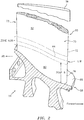
FIG. 2 is a partial cross-sectional illustration of a rotor hub of the gas turbine engine. -
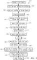
FIG. 3 illustrates a flow diagram of an example method to form a rotor hub. -
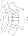
FIG. 4 illustrates a cross-sectional view of one-half of a circumferential tool for stress relieving the linear friction welds of each of the multiple of stubs within a predefined area on the stub-containing rotor hub forging and airfoil of an integrally bladed rotor. -
FIG. 5 illustrates a pictorial view of the 2-piece circumferential tool for stress relieving the linear friction welds of each of the multiple of stubs within a predefined area on the stub-containing rotor hub forging and airfoil of an integrally bladed rotor. -
FIG. 1 schematically illustrates agas turbine engine 20. Thegas turbine engine 20 as disclosed herein is a two-spool turbofan that generally incorporates afan section 22, acompressor section 24, acombustor section 26, and aturbine section 28. Thefan section 22 drives air along a bypass flowpath while thecompressor section 24 drives air along a core flowpath for compression and communication into thecombustor section 26, then expansion through theturbine section 28. Although depicted as a high bypass gas turbofan engine architecture in the disclosed non-limiting embodiment, it should be appreciated that the concepts described herein are not limited only thereto. - The
engine 20 generally includes alow spool 30 and ahigh spool 32 mounted for rotation around an engine central longitudinal axis A relative to anengine case structure 36 viaseveral bearings 38. Thelow spool 30 generally includes aninner shaft 40 that interconnects afan 42, a low pressure compressor ("LPC") 44 and a low pressure turbine ("LPT") 46. Theinner shaft 40 drives thefan 42 directly or through a gearedarchitecture 48 to drive thefan 42 at a lower speed than thelow spool 30. An exemplary reduction transmission is an epicyclic transmission, namely a planetary or star gear system. Thehigh spool 32 includes anouter shaft 50 that interconnects a high pressure compressor ("HPC") 52 and high pressure turbine ("HPT") 54. Acombustor 56 is arranged between the HPC 52 and the HPT 54. - The
fan 42 includes arotor hub 58 with a plurality of circumferentially spacedfan blades 60. Anose cone 64 may be fastened to an upstream end of therotor hub 58. The rotor may be provided in the form of an integrally bladed rotor (IBR; also, known as a blisk) which may be manufactured of a high-strength, low weight material such as a titanium alloy (typically Ti-6-4 alloy), high strength nickel base alloy, or other material. Although an example fan is illustrated and described in the disclosed embodiments, other components may also benefit herefrom. - With reference to
FIG. 2 , the plurality offan blades 60 are integrally formed with, and substantially radially extending from, therotor hub 58. Each of thefan blades 60 defines anairfoil 70 which has a leadingedge 72 andtrailing edge 73 that extends from ablade root 76 to ablade tip 78. Thefan blades 60 are integrated with therotor hub 58 such that thefan blades 60 are integrally formed as a monolithic component with therotor hub 58 to form an integrallybladed rotor 59. Eachairfoil 70 is formed from anairfoil stub 80 that is machined into therotor hub 58 and anairfoil section 82 that is linear friction welded (LFW) to theairfoil stub 80 at alinear friction weld 84 in apredetermined area 86. - With reference to
FIG. 3 , one non-limiting embodiment of amethod 200 for producing the integrally bladedrotor 59 is disclosed. Initially, a cast ingot is forged (202). The forged ingot is then solution heat treated and annealed (204). The solution heat temperature varies from heat-to-heat of material due to chemistry variation. Each heat of Ti-6-4 material has a beta transus established by the mill. A solution heat treatment temperature is defined for each part based on the beta transus temperature, which is the lowest temperature at which a 100 percent beta phase can exist. For example, the forged ingot may be heated in argon, a vacuum, or air, to a temperature within the range of 50 - 65 degrees F (10-18 degrees C) below beta transus; then held at the selected temperature ±15 degrees F (± 9 degrees C) for 1 hour; then cooled at a rate equivalent to rapid air cool or faster; then annealed at 1300 degrees F (704 degrees C) in argon, a vacuum, or air; held at heat for 2 hours; then cooled at a rate equivalent to air cool; and descaled as necessary. - The forged ingot is then machined to a sonic shape (206). A sonic shape is a rectilinear machined shape that is created from the forged ingot. The rectilinear shape facilitates sonic inspection. The sonic shape is then sonic inspected (208).
- Next, the sonic shape is machined (210) to fabricate a stub-containing rotor hub forging. The stub-containing rotor hub forging is a nearer-net shape for linear friction welding (LFW) to the
stubs 80. Optionally, a warm-working step (212) of the machinedstubs 80 is provided for potential mechanical property/grain structure improvement. - The stub-containing rotor hub forging is then re-solution heat treated (214) using the same beta transus temperature that the mill used for its solution heat treatment. In one example, the stub-containing rotor hub forging is re-solution heat treated to a temperature in an upper portion of an acceptable solution temperature range. Alternatively, the machining of the stub-containing rotor is performed prior to the forging's initial solution heat treatment, thus making a re-solution step unnecessary.
- Next, the solution heat treated stub-containing rotor hub forging is then water quenched (216). Alternatively, a warm-working step (218) of the machined stubs is next provided for enhanced aging and enhanced mechanical properties within the stub-to-inner flow path region. The water quenched stub-containing rotor hub forging is then aged (220). In one example, the stub-containing rotor hub forging is aged within a furnace at 1000F for 6 hours.
- The aged hub is then further machined to prepare for linear friction welding of the airfoils to the stubs (222).
- An airfoil is then linear friction welded onto each of the stubs (224). One example shows the temperature at the
linear friction weld 84 to be 2300 degrees F (1260 degrees C) and the temperature 0.125 inches (3.175 mm) on either side of thelinear friction weld 84 is below 1000 degrees F (538 degrees C). Upon completion of all linear friction welding, theIBR 59 is machined to remove the airfoil collars, remove the LFW flash, and reduce the size of the stubs to which the airfoils were linear friction welded (225). - Next, each of the multiple of linear friction welds 84 is concurrently locally stress relieved within the predetermined area 86 (
FIG. 2 ) (226). In one example, thepredetermined area 86 is stress relieved at 1100 degrees F (593 degrees C) for 6 hours. Localized stress relief within the predeterminedarea 86 stress relieves thelinear friction weld 84, yet ensures that thestubs 80 near a hub outer diameter 88 (FIG. 2 ) and the airfoil outwardly span wise to some design-determined outer diameter will not exceed 1000 degrees F (538 degrees C). This protects the improved fatigue and tensile properties previously achieved in (220). In one example, thepredetermined area 86 is located at a distance greater than 0.375 inches (9.5 mm), but less than 3 inches (75 mm) from the hubouter diameter 88. In a more specific example, thepredetermined area 86 is greater than 1.5 inches (38 mm) from the hubouter diameter 88. The total width of the predeterminedarea 86 in this example is approximately 0.250 inches (8mm), but varies depending upon the IBR size. - With reference to
FIG. 4 , thepredetermined area 86 may be stress relieved with aheat treat fixture 300 that mounts around eachairfoil 70 at the interface between therespective airfoil stub 80 andairfoil section 82 to span the predeterminedarea 86. Theheat treat fixture 300 may be manufactured of a ceramic material to contain a multiple of heaters 302 (FIG. 5 ) that produce the desired radiant heat. Theheaters 302 may be, for example, calorimetric heating rods or Calrod® tubular heaters manufactured by Wattco Inc. of Lachine, QC Canada. A multiple ofthermocouples 304 may also be located in theheat treat fixture 300 to closely control the temperature of the multiple ofheaters 302 in thepredetermined areas 86 for eachairfoil 70 in response to a control system 310 (FIG. 5 ). - In another embodiment, the
airfoil section 82, that is linear friction welded (LFW) to theairfoil stub 80, may be of an equivalent or different material to hybrid nickel. For example, a hybridnickel alloy stub 80 may be a semi-heat treated (or fully heat treated) nickel alloy hub of one material, with airfoils of a different nickel alloy linear friction welded onto the airfoil stubs 80, then subsequently locally stabilization and/or precipitation heat treated within the predeterminedarea 86, while maintaining a specified maximum temperature near the hubouter diameter 88 and outwardly span wise to theairfoil tips 78. - The
control system 310 may include at least one processor (e.g., a controller, microprocessor, microcontroller, digital signal processor, etc.), a memory, and an input/output (I/O) subsystem. Thecontrol system 310 may be embodied as any type of computing device. The processor and the I/O subsystem are communicatively coupled to the memory. The memory may be embodied as any type of computer memory device (e.g., volatile memory such as various forms of random access memory). The I/O subsystem may be communicatively coupled to a number of hardware, firmware, and/or software components, including a data storage device, a display, a communication subsystem, a user interface (UI) subsystem, the multiple ofheaters 302, the multiple ofthermocouples 304, and apower source 306. - The integrally bladed
rotor 59 is then finish machined to a final configuration (228). - The
method 200 for producing the integrally bladedrotor 59 potentially increases high cycle fatigue (HCF) strength by as much as 30% at 250 degrees F (482 degrees C), plus increases 0.2% yield and tensile strengths by as much as 15% at 250 degrees F (482 degrees C) compared to conventional processes. The increased HCF and tensile strengths can be leveraged to increase life for an existing weight. Alternatively, if life is held constant, the improved mechanical properties enables reduced part weight. - Although the different non-limiting embodiments have specific illustrated components, the embodiments of this invention are not limited to those particular combinations. It is possible to use some of the components or features from any of the non-limiting embodiments in combination with features or components from any of the other non-limiting embodiments.
- It should be appreciated that relative positional terms such as "forward", "aft", "upper", "lower", "above", "below", and the like are with reference to the normal operational attitude of the vehicle and should not be considered otherwise limiting.
- It should be appreciated that like reference numerals identify corresponding or similar elements throughout the several drawings. It should also be appreciated that although a particular component arrangement is disclosed in the illustrated embodiments, other arrangements will benefit herefrom.
- Although particular step sequences are shown, described, and claimed, it should be appreciated that steps may be performed in any order, separated or combined unless otherwise indicated and will still benefit from the present disclosure.
- The foregoing description is exemplary rather than defined by the limitations within. Various non-limiting embodiments are disclosed herein; however, one of ordinary skill in the art would recognize that various modifications and variations in light of the above teachings will fall within the scope of the appended claims. It is therefore to be appreciated that within the scope of the appended claims, the disclosure may be practiced other than as specifically described. For that reason, the appended claims should be studied to determine true scope and content.
Claims (15)
- A method (200) for producing a rotor hub, comprising:solution heat treating a stub-containing rotor hub forging;water quenching the solution heat treated stub-containing rotor hub forging;aging the water quenched stub-containing rotor hub forging;linear friction welding airfoils (82) onto each of a multiple of stubs (80) of the stub-containing rotor hub forging; andconcurrently stress relieving the linear friction welds (84) of each of the multiple of stubs (80) at least within a predefined area while ensuring that a hub outer diameter (88) does not exceed a predetermined temperature, optionally wherein the predetermined temperature is 537.8 degrees C (1000 degrees F).
- The method (200) as recited in claim 1, wherein concurrently stress relieving the linear friction welds (84) of each of the multiple of stubs (80) comprises maintaining the predefined area at 593.3 degrees C (1100 degrees F) for a predetermined time period, optionally wherein the predetermined time period is 6 hours.
- The method (200) as recited in any preceding claim, further comprising warm-working the multiple of stubs (80) prior to the solution heat treating.
- The method (200) as recited in claim 1 or 2, further comprising warm-working the multiple of stubs (80) subsequent to the solution heat treating and prior to the aging the water quenched stub-containing rotor hub forging.
- The method (200) as recited in any preceding claim, further comprising machining the stub-containing rotor hub forging to a sonic shape prior to the solution heat treating.
- The method (200) as recited in any preceding claim, wherein stress relieving the linear friction welds (84) of each of the multiple of stubs (80) is only within the predefined area.
- An integrally bladed rotor (59), comprising:a stub-containing rotor hub forging; andan airfoil (70) linear friction welded onto each of a multiple of stubs (80) of the stub-containing rotor hub forging, wherein each of the airfoils (70) and each of the multiple of stubs (80) are stress relieved within a predefined area.
- The integrally bladed rotor (59) as recited in claim 7, wherein the predefined area is defined span wise along each of the airfoils (70) and each of the multiple of stubs (80).
- The integrally bladed rotor (59) as recited in claim 7 or 8, wherein the predefined area is displaced from an outer diameter (88) of a hub of the stub-containing rotor hub forging.
- The integrally bladed rotor (59) as recited in claim 9, wherein the predefined area is greater than 2.54 centimeters (1 inch) from an outer diameter (88) of a hub of the stub-containing rotor hub forging.
- The integrally bladed rotor (59) as recited in claim 9, wherein the predefined area is greater than 0.953 centimeters (0.375 inches) and less than 7.62 centimeters (3 inches) from the outer diameter (88) of the hub of the stub-containing rotor hub forging.
- The integrally bladed rotor (59) as recited in claim 11, wherein the predefined area is greater than 1.27 centimeters (0.5 inches) and less than 5.08 centimeters (2 inches) from an outer diameter (88) of a hub of the stub-containing rotor hub forging.
- The integrally bladed rotor (59) as recited in any of claims 7 to 12, wherein the stub-containing rotor hub forging is a titanium forging.
- The integrally bladed rotor (59) as recited in any of claims 7 to 13, wherein each of the airfoils (70) are hollow.
- The integrally bladed rotor (59) as recited in any of claims 7 to 13, wherein each of the airfoils (70) are solid.
Applications Claiming Priority (1)
| Application Number | Priority Date | Filing Date | Title |
|---|---|---|---|
| US15/863,163 US10633731B2 (en) | 2018-01-05 | 2018-01-05 | Method for producing enhanced fatigue and tensile properties in integrally bladed rotor forgings |
Publications (1)
| Publication Number | Publication Date |
|---|---|
| EP3508609A1 true EP3508609A1 (en) | 2019-07-10 |
Family
ID=65003310
Family Applications (1)
| Application Number | Title | Priority Date | Filing Date |
|---|---|---|---|
| EP19150589.0A Pending EP3508609A1 (en) | 2018-01-05 | 2019-01-07 | Method for producing enhanced fatigue and tensile properties in integrally bladed rotor forgings |
Country Status (2)
| Country | Link |
|---|---|
| US (1) | US10633731B2 (en) |
| EP (1) | EP3508609A1 (en) |
Cited By (2)
| Publication number | Priority date | Publication date | Assignee | Title |
|---|---|---|---|---|
| CN113319419A (en) * | 2021-05-17 | 2021-08-31 | 东莞材料基因高等理工研究院 | Device and method for improving mechanical property of aluminum alloy linear friction welding joint |
| CN119413423A (en) * | 2024-10-17 | 2025-02-11 | 中国航发南方工业有限公司 | A tensile testing device and method for an aircraft engine compressor rotor |
Families Citing this family (2)
| Publication number | Priority date | Publication date | Assignee | Title |
|---|---|---|---|---|
| US10935037B2 (en) * | 2018-01-05 | 2021-03-02 | Raytheon Technologies Corporation | Tool for simultaneous local stress relief of each of a multiple of linear friction welds of a rotor forging |
| CN113458724B (en) * | 2021-06-26 | 2022-12-06 | 成都凯迪精工科技有限责任公司 | Processing method of ultrahigh-strength steel high-aspect-ratio wind tunnel test model part |
Citations (4)
| Publication number | Priority date | Publication date | Assignee | Title |
|---|---|---|---|---|
| US4873751A (en) * | 1988-12-27 | 1989-10-17 | United Technologies Corporation | Fabrication or repair technique for integrally bladed rotor assembly |
| US20030000602A1 (en) * | 2001-04-17 | 2003-01-02 | Smith Michael P. | Integrally bladed rotor airfoil fabrication and repair techniques |
| EP2620516A2 (en) * | 2012-01-30 | 2013-07-31 | United Technologies Corporation | Method and apparatus of heat treating an integrally bladed rotor |
| EP3143171A2 (en) * | 2014-05-15 | 2017-03-22 | General Electric Company | Titanium alloys and their methods of production |
Family Cites Families (20)
| Publication number | Priority date | Publication date | Assignee | Title |
|---|---|---|---|---|
| DE19831736C2 (en) | 1998-07-15 | 2000-05-31 | Mtu Muenchen Gmbh | Method for repairing and manufacturing an integrally bladed rotor for a turbomachine |
| US6551372B1 (en) * | 1999-09-17 | 2003-04-22 | Rolls-Royce Corporation | High performance wrought powder metal articles and method of manufacture |
| IT1319834B1 (en) * | 2000-02-14 | 2003-11-03 | Teksid Spa | PROCEDURE FOR THE PRODUCTION OF LIGHT ALLOY CASTINGS. |
| US7449075B2 (en) * | 2004-06-28 | 2008-11-11 | General Electric Company | Method for producing a beta-processed alpha-beta titanium-alloy article |
| US7560065B2 (en) * | 2004-10-08 | 2009-07-14 | Igor Troitski | Method and system for manufacturing of multi-component complex shape parts consisting of monolithic and powder materials working at different performance conditions |
| DE102005006047A1 (en) | 2005-02-10 | 2006-09-07 | Mtu Aero Engines Gmbh | Method for producing and / or repairing an integrally bladed rotor |
| US7358466B1 (en) | 2006-01-12 | 2008-04-15 | General Electric Company | Localized heat treating apparatus for blisk airfoils |
| US20090185908A1 (en) * | 2008-01-21 | 2009-07-23 | Honeywell International, Inc. | Linear friction welded blisk and method of fabrication |
| US8414267B2 (en) * | 2009-09-30 | 2013-04-09 | General Electric Company | Multiple alloy turbine rotor section, welded turbine rotor incorporating the same and methods of their manufacture |
| US20120279066A1 (en) * | 2011-05-06 | 2012-11-08 | United Technologies Corporation | WELDING Ti-6246 INTEGRALLY BLADED ROTOR AIRFOILS |
| US8437628B1 (en) * | 2011-07-18 | 2013-05-07 | United Technologies Corporation | Method and apparatus of heat treating an integrally bladed rotor |
| US20140093384A1 (en) * | 2012-09-28 | 2014-04-03 | United Technologies Corporation | Method of Manufacturing Complex Shaped Component |
| US20140140859A1 (en) * | 2012-09-28 | 2014-05-22 | United Technologies Corporation | Uber-cooled multi-alloy integrally bladed rotor |
| US20140117007A1 (en) | 2012-10-29 | 2014-05-01 | General Electric Company | Local Heat Treatment and Thermal Management System for Engine Components |
| EP3019723A4 (en) * | 2013-07-09 | 2017-05-10 | United Technologies Corporation | Plated polymer compressor |
| WO2015009454A1 (en) * | 2013-07-15 | 2015-01-22 | United Technologies Corporation | Turbine clearance control utilizing low alpha material |
| RU2551045C1 (en) | 2013-11-21 | 2015-05-20 | Федеральное государственное бюджетное образовательное учреждение высшего профессионального образования "Уфимский государственный авиационный технический университет" | Method of thermal treatment of weld joints produced by linear friction welding |
| US20170268091A1 (en) * | 2014-04-18 | 2017-09-21 | General Electric Company | Titanium alloys and their methods of production |
| US9951632B2 (en) * | 2015-07-23 | 2018-04-24 | Honeywell International Inc. | Hybrid bonded turbine rotors and methods for manufacturing the same |
| US10718041B2 (en) * | 2017-06-26 | 2020-07-21 | Raytheon Technologies Corporation | Solid-state welding of coarse grain powder metallurgy nickel-based superalloys |
-
2018
- 2018-01-05 US US15/863,163 patent/US10633731B2/en active Active
-
2019
- 2019-01-07 EP EP19150589.0A patent/EP3508609A1/en active Pending
Patent Citations (4)
| Publication number | Priority date | Publication date | Assignee | Title |
|---|---|---|---|---|
| US4873751A (en) * | 1988-12-27 | 1989-10-17 | United Technologies Corporation | Fabrication or repair technique for integrally bladed rotor assembly |
| US20030000602A1 (en) * | 2001-04-17 | 2003-01-02 | Smith Michael P. | Integrally bladed rotor airfoil fabrication and repair techniques |
| EP2620516A2 (en) * | 2012-01-30 | 2013-07-31 | United Technologies Corporation | Method and apparatus of heat treating an integrally bladed rotor |
| EP3143171A2 (en) * | 2014-05-15 | 2017-03-22 | General Electric Company | Titanium alloys and their methods of production |
Cited By (2)
| Publication number | Priority date | Publication date | Assignee | Title |
|---|---|---|---|---|
| CN113319419A (en) * | 2021-05-17 | 2021-08-31 | 东莞材料基因高等理工研究院 | Device and method for improving mechanical property of aluminum alloy linear friction welding joint |
| CN119413423A (en) * | 2024-10-17 | 2025-02-11 | 中国航发南方工业有限公司 | A tensile testing device and method for an aircraft engine compressor rotor |
Also Published As
| Publication number | Publication date |
|---|---|
| US10633731B2 (en) | 2020-04-28 |
| US20190211433A1 (en) | 2019-07-11 |
Similar Documents
| Publication | Publication Date | Title |
|---|---|---|
| US11448227B2 (en) | Tool for simultaneous local stress relief of each of a multiple of linear friction welds of a rotor forging | |
| EP3508609A1 (en) | Method for producing enhanced fatigue and tensile properties in integrally bladed rotor forgings | |
| KR100509544B1 (en) | Methods for fabrication and repair of integrally bladed rotor airfoil | |
| EP1526252B1 (en) | Method for preparing a tri-property rotor assembly of a turbine engine | |
| JP7171668B2 (en) | Titanium alloy and its manufacturing method | |
| US4479293A (en) | Process for fabricating integrally bladed bimetallic rotors | |
| EP3453484B1 (en) | Process of making integrally bladed rotor and integrally bladed rotor | |
| EP2520762B1 (en) | Welding Ti-6246 integrally bladed rotor airfoils | |
| JP2008163937A (en) | Rotating assembly parts and parts manufacturing method | |
| EP3995594B1 (en) | Solid-state welding of coarse grain powder metallurgy nickel-based superalloys | |
| JP2007513780A (en) | Manufacturing method of compressor rotor | |
| EP3453483A1 (en) | Method of making integrally bladed rotor | |
| EP0328476A2 (en) | Method for fabricating integrally bladed rotors | |
| EP3399059A1 (en) | Composition and method for enhanced precipitation hardened superalloys | |
| CN115870436A (en) | Two-stage disc and manufacturing method thereof | |
| EP3450583A1 (en) | High yield strength nickel alloy with augmented precipitation hardening |
Legal Events
| Date | Code | Title | Description |
|---|---|---|---|
| PUAI | Public reference made under article 153(3) epc to a published international application that has entered the european phase |
Free format text: ORIGINAL CODE: 0009012 |
|
| STAA | Information on the status of an ep patent application or granted ep patent |
Free format text: STATUS: THE APPLICATION HAS BEEN PUBLISHED |
|
| AK | Designated contracting states |
Kind code of ref document: A1 Designated state(s): AL AT BE BG CH CY CZ DE DK EE ES FI FR GB GR HR HU IE IS IT LI LT LU LV MC MK MT NL NO PL PT RO RS SE SI SK SM TR |
|
| AX | Request for extension of the european patent |
Extension state: BA ME |
|
| STAA | Information on the status of an ep patent application or granted ep patent |
Free format text: STATUS: REQUEST FOR EXAMINATION WAS MADE |
|
| 17P | Request for examination filed |
Effective date: 20200110 |
|
| RBV | Designated contracting states (corrected) |
Designated state(s): AL AT BE BG CH CY CZ DE DK EE ES FI FR GB GR HR HU IE IS IT LI LT LU LV MC MK MT NL NO PL PT RO RS SE SI SK SM TR |
|
| STAA | Information on the status of an ep patent application or granted ep patent |
Free format text: STATUS: EXAMINATION IS IN PROGRESS |
|
| 17Q | First examination report despatched |
Effective date: 20200512 |
|
| RAP1 | Party data changed (applicant data changed or rights of an application transferred) |
Owner name: RAYTHEON TECHNOLOGIES CORPORATION |
|
| RAP3 | Party data changed (applicant data changed or rights of an application transferred) |
Owner name: RTX CORPORATION |
|
| RIC1 | Information provided on ipc code assigned before grant |
Ipc: B23K 103/18 20060101ALN20250415BHEP Ipc: B23K 103/14 20060101ALN20250415BHEP Ipc: B23K 101/00 20060101ALN20250415BHEP Ipc: B23K 20/26 20060101ALI20250415BHEP Ipc: F01D 5/34 20060101ALI20250415BHEP Ipc: F01D 5/30 20060101ALI20250415BHEP Ipc: C22F 1/18 20060101ALI20250415BHEP Ipc: B23K 20/24 20060101ALI20250415BHEP Ipc: B23K 20/233 20060101ALI20250415BHEP Ipc: B23K 20/12 20060101ALI20250415BHEP Ipc: B23P 15/00 20060101ALI20250415BHEP Ipc: C22F 1/00 20060101AFI20250415BHEP |