EP3508298A1 - High reliability modular and reconfigurable welding power supply systems - Google Patents
High reliability modular and reconfigurable welding power supply systems Download PDFInfo
- Publication number
- EP3508298A1 EP3508298A1 EP18215366.8A EP18215366A EP3508298A1 EP 3508298 A1 EP3508298 A1 EP 3508298A1 EP 18215366 A EP18215366 A EP 18215366A EP 3508298 A1 EP3508298 A1 EP 3508298A1
- Authority
- EP
- European Patent Office
- Prior art keywords
- power supply
- module
- welding
- cutting
- electrical
- Prior art date
- Legal status (The legal status is an assumption and is not a legal conclusion. Google has not performed a legal analysis and makes no representation as to the accuracy of the status listed.)
- Withdrawn
Links
- 238000003466 welding Methods 0.000 title claims abstract description 143
- 238000005520 cutting process Methods 0.000 claims abstract description 135
- 238000002955 isolation Methods 0.000 claims description 6
- 230000015654 memory Effects 0.000 description 6
- 238000000034 method Methods 0.000 description 6
- 230000001360 synchronised effect Effects 0.000 description 6
- 238000013461 design Methods 0.000 description 5
- 238000012986 modification Methods 0.000 description 3
- 230000004048 modification Effects 0.000 description 3
- 230000006870 function Effects 0.000 description 2
- 230000007246 mechanism Effects 0.000 description 2
- 230000000116 mitigating effect Effects 0.000 description 2
- 230000002093 peripheral effect Effects 0.000 description 2
- 230000000007 visual effect Effects 0.000 description 2
- 230000004075 alteration Effects 0.000 description 1
- 238000004891 communication Methods 0.000 description 1
- 238000012937 correction Methods 0.000 description 1
- 230000003993 interaction Effects 0.000 description 1
- 230000002452 interceptive effect Effects 0.000 description 1
- 239000004973 liquid crystal related substance Substances 0.000 description 1
- 230000003287 optical effect Effects 0.000 description 1
- 230000002085 persistent effect Effects 0.000 description 1
- 238000012545 processing Methods 0.000 description 1
- 238000009966 trimming Methods 0.000 description 1
Images



Classifications
-
- B—PERFORMING OPERATIONS; TRANSPORTING
- B23—MACHINE TOOLS; METAL-WORKING NOT OTHERWISE PROVIDED FOR
- B23K—SOLDERING OR UNSOLDERING; WELDING; CLADDING OR PLATING BY SOLDERING OR WELDING; CUTTING BY APPLYING HEAT LOCALLY, e.g. FLAME CUTTING; WORKING BY LASER BEAM
- B23K9/00—Arc welding or cutting
- B23K9/10—Other electric circuits therefor; Protective circuits; Remote controls
- B23K9/1006—Power supply
- B23K9/1043—Power supply characterised by the electric circuit
-
- B—PERFORMING OPERATIONS; TRANSPORTING
- B23—MACHINE TOOLS; METAL-WORKING NOT OTHERWISE PROVIDED FOR
- B23K—SOLDERING OR UNSOLDERING; WELDING; CLADDING OR PLATING BY SOLDERING OR WELDING; CUTTING BY APPLYING HEAT LOCALLY, e.g. FLAME CUTTING; WORKING BY LASER BEAM
- B23K9/00—Arc welding or cutting
- B23K9/095—Monitoring or automatic control of welding parameters
-
- B—PERFORMING OPERATIONS; TRANSPORTING
- B23—MACHINE TOOLS; METAL-WORKING NOT OTHERWISE PROVIDED FOR
- B23K—SOLDERING OR UNSOLDERING; WELDING; CLADDING OR PLATING BY SOLDERING OR WELDING; CUTTING BY APPLYING HEAT LOCALLY, e.g. FLAME CUTTING; WORKING BY LASER BEAM
- B23K9/00—Arc welding or cutting
- B23K9/10—Other electric circuits therefor; Protective circuits; Remote controls
- B23K9/1006—Power supply
- B23K9/1043—Power supply characterised by the electric circuit
- B23K9/1056—Power supply characterised by the electric circuit by using digital means
- B23K9/1062—Power supply characterised by the electric circuit by using digital means with computing means
-
- B—PERFORMING OPERATIONS; TRANSPORTING
- B23—MACHINE TOOLS; METAL-WORKING NOT OTHERWISE PROVIDED FOR
- B23K—SOLDERING OR UNSOLDERING; WELDING; CLADDING OR PLATING BY SOLDERING OR WELDING; CUTTING BY APPLYING HEAT LOCALLY, e.g. FLAME CUTTING; WORKING BY LASER BEAM
- B23K9/00—Arc welding or cutting
- B23K9/10—Other electric circuits therefor; Protective circuits; Remote controls
- B23K9/1006—Power supply
- B23K9/1043—Power supply characterised by the electric circuit
- B23K9/1068—Electric circuits for the supply of power to two or more arcs from a single source
-
- B—PERFORMING OPERATIONS; TRANSPORTING
- B23—MACHINE TOOLS; METAL-WORKING NOT OTHERWISE PROVIDED FOR
- B23K—SOLDERING OR UNSOLDERING; WELDING; CLADDING OR PLATING BY SOLDERING OR WELDING; CUTTING BY APPLYING HEAT LOCALLY, e.g. FLAME CUTTING; WORKING BY LASER BEAM
- B23K9/00—Arc welding or cutting
- B23K9/10—Other electric circuits therefor; Protective circuits; Remote controls
- B23K9/1006—Power supply
- B23K9/1075—Parallel power supply, i.e. multiple power supplies or multiple inverters supplying a single arc or welding current
-
- B—PERFORMING OPERATIONS; TRANSPORTING
- B23—MACHINE TOOLS; METAL-WORKING NOT OTHERWISE PROVIDED FOR
- B23K—SOLDERING OR UNSOLDERING; WELDING; CLADDING OR PLATING BY SOLDERING OR WELDING; CUTTING BY APPLYING HEAT LOCALLY, e.g. FLAME CUTTING; WORKING BY LASER BEAM
- B23K9/00—Arc welding or cutting
- B23K9/32—Accessories
-
- H—ELECTRICITY
- H05—ELECTRIC TECHNIQUES NOT OTHERWISE PROVIDED FOR
- H05K—PRINTED CIRCUITS; CASINGS OR CONSTRUCTIONAL DETAILS OF ELECTRIC APPARATUS; MANUFACTURE OF ASSEMBLAGES OF ELECTRICAL COMPONENTS
- H05K5/00—Casings, cabinets or drawers for electric apparatus
- H05K5/02—Details
- H05K5/0256—Details of interchangeable modules or receptacles therefor, e.g. cartridge mechanisms
- H05K5/0286—Receptacles therefor, e.g. card slots, module sockets, card groundings
Definitions
- the invention is related to a reconfigurable multi-arc system according to claims 1 and 7 and to a reconfigurable system according to claim 14.
- Embodiments of the present invention relate to systems associated with a welding or cutting environment. More specifically, embodiments of the present invention relate to reconfigurable systems for generating one or more arcs for welding or cutting.
- many welding or cutting power supplies may be located at various locations within the welding or cutting environment to support various welding or cutting operations throughout the environment.
- a power supply has a problem and shuts down, the corresponding welding or cutting operation is also shut down until the problem can be resolved.
- Embodiments of the present invention include systems to support the generation of one or more (multiple) arcs for welding or plasma cutting in a welding or cutting environment (e.g., a factory).
- a reconfigurable modular power supply system provides redundancy, improved reliability, improved up-time, and improved serviceability across the welding or cutting environment. Such improvements are achieved by the implementation of hot-swappable power supply modules in a reconfigurable module rack.
- power supply modules that are hot-swappable are power supply modules that can be removed from and inserted into a module rack without stopping or shutting down the associated welding or cutting system (i.e., without interruption to the on-going welding or cutting operation). Hot-swapping can be achieved by rack and module design particulars as well as by employing a controller implementing hot-swapping control techniques, as discussed later herein.
- One embodiment includes a system to support the generation of multiple arcs for welding or cutting within a welding or cutting environment.
- the system includes a module rack having a plurality of module slots.
- the module rack is configured to accept electrical input power from a single power drop within the welding or cutting environment via a power disconnect box.
- the system also includes a plurality of power supply modules (e.g., hot-swappable power supply modules) configured to be respectively inserted into and withdrawn from the plurality of module slots.
- Each power supply module is configured to accept an electrical AC input derived from the electrical input power and provide an electrical DC output.
- the module rack is configured to support reconfigurable parallel electrical connections of subsets of the power supply modules inserted into the module rack.
- the system further includes a plurality of output power supply stages.
- each output power supply stage is configured to connect to an electrical output of a separate subset of the subsets of the power supply modules.
- Each output power supply stage is configured to provide a dynamic waveform-controlled welding or cutting electrical signal to support the generation of a single arc, of the multiple arcs, between an electrode and a workpiece for welding or cutting.
- the system also includes a controller operatively interfacing to the module rack, in one embodiment. The controller is configured to define and electrically connect in parallel a first subset of the power supply modules within the module rack.
- each power supply module includes a first power supply stage and a second power supply stage.
- each power supply module includes an AC to DC converter circuit.
- each power supply module includes an unregulated DC to DC converter circuit.
- each power supply module includes an inverter circuit with an isolation transformer and a rectifier circuit.
- each output power supply stage includes a chopper circuit.
- each output power supply stage is configured to be located remotely from the module rack and be electrically connected to the module rack via an electrical cable. In another embodiment, each output power supply stage is configured to be located within the module rack.
- One embodiment includes a system to support the generation of multiple arcs for welding or cutting within a welding or cutting environment.
- the system includes a module rack having a plurality of module slots.
- the module rack is configured to accept electrical input power from a single power drop within the welding or cutting environment via a power disconnect box.
- the system also includes a plurality of power supply modules (e.g., hot-swappable power supply modules) configured to be respectively inserted into and withdrawn from the plurality of module slots.
- Each power supply module is configured to accept an electrical AC input derived from the electrical input power and provide an electrical DC output.
- Each power supply module is also configured to provide a dynamic waveform-controlled output signal.
- the module rack is configured to support reconfigurable parallel electrical connections of subsets of the power supply modules inserted into the module rack.
- the system also includes a controller operatively interfacing to the module rack and configured to synchronize the dynamic waveform-controlled output signal of each power supply module, within each subset, with each other to provide a welding or cutting electrical signal from each subset. Synchronization of the dynamic waveform-controlled output signals of each subset is based on feedback information from each corresponding subset, in accordance with one embodiment.
- the welding or cutting electrical signal from each subset supports generation of a single arc, of the multiple arcs, between an electrode and a workpiece for welding or cutting.
- the controller is configured to define and electrically connect in parallel a first subset of the power supply modules within the module rack.
- the controller is also configured to electrically connect a newly inserted power supply module into the first subset while avoiding generating electrical surges within the module rack, and while avoiding generating disturbances in a first welding or cutting electrical signal associated with the first subset during a first welding or cutting operation.
- the controller is configured to report a failure of a power supply module to an external reporting system.
- each power supply module includes a first power supply stage, a second power supply stage, and a third power supply stage.
- each power supply module includes an AC to DC converter circuit.
- each power supply module includes an unregulated DC to DC converter circuit.
- each power supply module includes an inverter circuit with an isolation transformer and a rectifier circuit.
- each power supply module includes a chopper circuit.
- One embodiment includes a system to support the generation of at least one arc for welding or cutting within a welding or cutting environment.
- the system includes a module rack having a plurality of module slots.
- the module rack is configured to accept electrical input power from a single power drop within a welding or cutting environment via a power disconnect box.
- the system includes a plurality of power supply modules (e.g., hot-swappable power supply modules) configured to be respectively inserted into and withdrawn from the plurality of module slots.
- the module rack is configured to support reconfigurable parallel electrical connections of the plurality of power supply modules inserted into the module rack.
- the system further includes a controller configured to electrically connect a newly replaced power supply module within the module rack while avoiding generating electrical surges within the module rack, and while avoiding generating disturbances in a welding or cutting electrical signal supported by the module rack during a welding or cutting operation.
- the controller is configured to report a failure of a power supply module to an external reporting system.
- Embodiments of reconfigurable systems to support the generation of one or more arcs for welding or cutting in a welding or cutting environment are disclosed.
- a reconfigurable multi-arc system is disclosed.
- the reconfigurable multi-arc system includes a module rack and multiple power supply modules (e.g., hot-swappable power supply modules) organized within the module rack to support the generation of multiple arcs for welding or cutting within a welding or cutting environment.
- power supply modules e.g., hot-swappable power supply modules
- FIG. 1 illustrates a first embodiment of a reconfigurable multi-arc system 100 to support the generation of multiple arcs for welding or plasma cutting in a welding or cutting environment.
- the reconfigurable multi-arc system 100 includes a module rack 110 having multiple module slots 115.
- Each module slot 115 is configured to have a power supply module inserted into and withdrawn from a slot in a hot-swappable manner.
- the power supply modules can support one or more welding or cutting operations.
- the power supply modules are hot-swappable and can be removed from and inserted into the module rack 110 without stopping or shutting down the associated welding or cutting system (i.e., without interruption to an on-going welding or cutting operation). Hot-swapping can be achieved by rack and module design particulars as well as by employing a controller implementing hot-swapping control techniques. An embodiment of a power supply module is discussed later herein with respect to FIG. 2 . In another embodiment, the power supply modules are not hot-swappable.
- the module rack 110 includes wiring and/or traces and controllable switches that support reconfigurable electrical connections of the power supply modules.
- the module rack 110 may include a reconfigurable backplane that allows various combinations or subsets of power supply modules to be electrically connected to each other.
- the reconfigurable backplane may be under the control of a programmable controller, for example, in accordance with one embodiment.
- the module rack 110 is configured to accept electrical input power (e.g., 460 VAC) from a single power drop within a welding or cutting environment via, for example, a power disconnect box having, for example, switches and fuses. Electrical power distributed to the inputs of individual power supply modules within the module rack 110 is derived from the electrical input power (e.g., under the control of a controller).
- the system 100 includes a controller 120 operatively interfacing to the module rack 110.
- the controller 120 is configured to define subsets of the power supply modules within the module rack 110.
- the controller 120 is also configured to command electrical connection of a defined subset of the power supply modules in parallel via the module rack (e.g. by reconfiguring a backplane of the module rack 110).
- Such a subset of power supply modules can be used in a welding or cutting operation to support generation of a single arc between an electrode and a workpiece for welding or cutting in a welding or cutting environment.
- the controller 120 provides flexibility in defining a subset of power supply modules within the module rack 110 to be electrically connected together in parallel. In the extreme, a subset can include a single power supply module.
- Redundancy can be provided by having the total power supplied by the multiple power supply modules within the module rack 110 be more than the total output power requirement from the module rack 110.
- the controller 120 is configured to reduce the output power when some of the power supply modules are down.
- the controller 120 is also configured to electrically connect a newly inserted hot-swappable power supply module into a subset while avoiding generating electrical surges within the module rack 110, and while avoiding generating disturbances in a welding or cutting electrical signal associated with the subset during a welding or cutting operation.
- the controller 120 can avoid the occurrence of such surges and disturbances by bringing a newly inserted power supply module on-line slowly (e.g., by slowly powering up the newly inserted power supply module) and/or by electrically connecting various input and output pins of the newly inserted power supply module in a particular order.
- the controller is configured to balance the power draw from each module by ramping up the power of a newly inserted module and ramping down the power of existing on-line modules, in accordance with one embodiment.
- the subsets of power supply modules are defined largely by the module rack 110.
- the module rack 110 For example, referring to FIG. 1 , five (5) rows of slots 115 are shown within the module rack 110 which can be populated with hot-swappable power supply modules.
- the first row defines a first subset corresponding to up to ten (10) modules.
- the second through fifth rows each define subsets corresponding to, respectively, up to ten (10), nine (9), eight (8), and seven (7) modules.
- the controller 120 is still used to support hot-swapping of the power supply modules to avoid surges and disturbances.
- each subset (row) of slots 115 which may be populated with hot-swappable power supply modules, can be electrically connected to a chopper circuit 130 serving as an output power supply stage.
- a chopper circuit 130 serving as an output power supply stage.
- Other types of output power supply stages are possible as well, in accordance with other embodiments.
- An electrical input of each output power supply stage 130 is configured to be connected to an electrical output of a separate subset of the hot-swappable power supply modules that are connected in parallel.
- Each output power supply stage 130 provides a dynamic waveform-controlled welding or cutting signal to support generation of a single arc between an electrode and a workpiece for welding or cutting.
- a dynamic waveform-controlled welding or cutting signal from an output power supply stage 130 may be provided to a welding gun/torch and/or welding wire feeder within a welding or cutting environment.
- the system 100 of FIG. 1 provides the dynamic welding or cutting voltages and currents to support various welding or cutting operations and modes.
- each output power supply stage 130 e.g., chopper circuit
- U.S. Patent Application No. 2015/0014290 A1 which is incorporated by reference herein, describes various configurations of output power supply stages that are controlled by a controller and/or a waveform generator.
- FIG. 2 illustrates a first embodiment of a hot-swappable power supply module 200 that may be used in the systems 100, 300, 400, and 500 of FIG. 1 , FIG. 3 , FIG. 4 , and FIG. 5 , respectively.
- the hot-swappable power supply module 200 is configured to be inserted into and withdrawn from, for example, any of the slots 115 in the module rack 110 in a hot-swappable manner.
- the hot-swappable power supply module 200 includes an electrical input connector 210, a first power supply stage 220, a second power supply stage 230, and an electrical output connector 240.
- the electrical input connector 210 is configured to accept electrical input power (e.g., AC input power). In one embodiment, the electrical input connector 210 is also configured to accept one or more control signals from a controller (e.g., from the controller 120 via a backplane of the module rack 110). The one or more control signals control the operations of the first power supply stage 220 and the second power supply stage 230, in accordance with one embodiment.
- a controller e.g., from the controller 120 via a backplane of the module rack 110.
- the one or more control signals control the operations of the first power supply stage 220 and the second power supply stage 230, in accordance with one embodiment.
- U.S. Patent Application No. 2015/0014290 A1 which is incorporated by reference herein, describes various types of first (I) and second (II) power supply stages that are controlled by a controller.
- the electrical output connector 240 is configured to output an unregulated electrical DC signal.
- the electrical output connector 240 is also configured to output one or more feedback signals to a controller (e.g., to the controller 120 via a backplane of the module rack 110).
- the feedback signals may be derived from, for example, an output voltage and/or an output current of the module 200, in accordance with one embodiment, which are used by the controller 120 to modify the control signals.
- the feedback signals can also include module status signals.
- a feedback signal can indicate when a particular module has failed (or has gone off-line).
- the controller can use the feedback information to report the failure to, for example, an external reporting system. As a result, a service call can be initiated to replace the failed module.
- the controller can use the feedback information to take the failed module off-line and bring another module on-line in its place within the associated subset of modules. In this manner, the operation (e.g., power, waveform, timing) and the status (e.g., failed module) of each power supply module can be monitored and controlled, and power supply modules can be taken off-line and brought on-line in a real-time, dynamic manner.
- the first power supply stage 220 is an AC to DC converter circuit.
- the second power supply stage 230 is an unregulated DC to DC converter circuit.
- the second power supply stage 230 may include an inverter circuit with an isolation transformer and a rectifier circuit.
- the first power supply stage 220 accepts an electrical AC input signal, derived from the electrical input power to the module rack 110, at the electrical input connector 210.
- the second power supply stage 230 outputs an electrical DC output signal at the electrical output connector 240.
- Providing an electrical AC input to the module 200 is facilitated by a backplane of the module rack 110, in accordance with one embodiment.
- routing the electrical DC output signal away from the electrical output connector 240 is facilitated by the backplane of the module rack 110, in accordance with one embodiment.
- the AC to DC converter circuit of the first power supply stage 220 is configured to provide a power factor correction function.
- a hot-swappable power supply module may have a single stage.
- a hot-swappable power supply module may have three stages. The numbers and types of stages depend on the design considerations and constraints associated with any particular application.
- each hot-swappable power supply module 200 provides 50 amps of electrical current. Therefore, a subset of such hot-swappable power supply modules 200 electrically connected in parallel can provide an electrical current of N x 50 amps, where N is the number of power supply modules 200 connected in parallel. Therefore, depending on the current need for a particular welding or cutting operation, the controller 120 can select the number N of power supply modules 200 to be electrically connected and used for that operation. In accordance with other embodiments, each hot-swappable power supply module 200 provides some other amount of electrical current (e.g. 25 amps, or 75 amps, or 100 amps).
- each output power supply stage 130 (e.g., a chopper circuit) is external to the module rack 110.
- the module rack 110 is centrally located within a welding or cutting environment, accepting electrical input power from a single power drop via a power disconnect box.
- Each chopper circuit 130 is located remotely from the module rack 110 at a robotic welding or cutting station within the welding or cutting environment and is electrically connected to the module rack 110 via electrical cables. In this way, a single module rack 110 can support the generation of multiple welding or cutting arcs throughout the welding or cutting environment.
- the DC outputs out of the module rack 110 are not affected by the inductance of the electrical cables connecting the module rack 110 to the various chopper circuits 130 at the welding or cutting stations. Therefore, fairly long cable lengths can be accommodated across a welding or cutting environment.
- FIG. 3 illustrates a second embodiment of a reconfigurable multi-arc system 300 to support the generation of multiple arcs for welding or cutting in a welding or cutting environment.
- the system 300 of Fig. 3 is similar to the system 100 of Fig. 1 in that the system 300 includes a module rack 310 having module slots 315 (similar to the module slots 115 to accept the modules 200), a controller 320 (similar to the controller 120), and output power supply stages (e.g., chopper circuits) 330 (similar to the output power supply stages 130). However, in the system 300 of FIG. 3 , the output power supply stages (e.g., chopper circuits) 330 are located within the module rack 310, not externally to the module rack 310.
- the output power supply stages e.g., chopper circuits
- the controller 320 can determine which chopper circuit 330 to connect to which subset of hot-swappable power supply modules via, for example, a backplane of the module rack 310. Furthermore, in accordance with one embodiment, the controller 320 also controls the operation of each of the output power supply stages 330. In accordance with another embodiment, each output power supply stage 330 may be controlled by a dedicated controller within the module rack 310.
- the system 300 of FIG. 3 may be desirable when used in a welding or cutting environment that is relatively small, mitigating the use of long cable lengths to the welding or cutting stations.
- FIG. 4 illustrates a first embodiment of a reconfigurable single-arc system 400 to support the generation of a single arc for welding or cutting in a welding or cutting environment.
- the system 400 includes a module rack 410 having module slots 415 to accommodate hot-swappable power supply modules (e.g., 200).
- the system also includes a controller 420 and an output power supply stage (e.g., a chopper circuit) 430.
- the system 400 is similar to a portion of the system 100 of FIG. 1 .
- the module rack 410 may be equivalent to the first row of the module rack 110 in FIG. 1 .
- the chopper circuit 430 may be equivalent to the chopper #1 130 in FIG. 1 .
- the controller 420 may be somewhat similar to the controller 120 in FIG. 1 .
- only the generation of a single arc is supported (e.g., at a robotic welding or cutting work station or at a manual welding or cutting work station) within a welding or cutting environment.
- the controller 420 determines which power supply modules to use to provide an electrical input to the chopper circuit 430.
- the controller 420 also allows the power supply modules to be replaced in the slots 415 in a hot-swappable manner.
- the controller 420 controls the operation of the chopper circuit 430.
- the controller 420 includes a waveform generator to facilitate the generation of a dynamic waveform-controlled welding or cutting electrical signal by the chopper circuit 430. Examples of controlling a chopper circuit via a waveform generator are disclosed in U.S. Patent Application No. 2015/0014290 A1 , which is incorporated by reference herein.
- the DC output out of the module rack 410 is not affected by the inductance of the electrical cable connecting the module rack 410 to the chopper circuit 430 at the welding or cutting station. Therefore, a fairly long cable length can be accommodated.
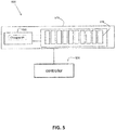
- FIG. 5 illustrates a second embodiment of a reconfigurable single-arc system 500 to support the generation of a single arc for welding or cutting in a welding or cutting environment.
- the system 500 is similar to the system 400 of FIG. 4 in that the system 500 includes a module rack 510 having module slots 515 (similar to the module slots 415 to accept the modules 200), a controller 520 (similar to the controller 420), and an output power supply stage (e.g., a chopper circuit) 530 (similar to the output power supply stage 430).
- the output power supply stage e.g., the chopper circuit
- the output power supply stage e.g., the chopper circuit
- the output power supply stage is located within the module rack 510, not externally to the module rack 510.
- the controller 520 determines which power supply modules to use to provide an electrical input to the chopper circuit 530.
- the controller 520 also allows the power supply modules to be replaced in the slots 515 in a hot-swappable manner.
- the controller 520 controls the operation of the chopper circuit 530.
- the system 500 of FIG. 5 may be desirable when used in a welding or cutting environment that is relatively small, mitigating the use of a long cable length to the welding or cutting station. In this manner, a smaller module rack can be provided to support a single arc operation.
- FIG. 6 illustrates a third embodiment of a reconfigurable multi-arc system 600 to support the generation of multiple arcs for welding or cutting in a welding or cutting environment.
- an output power supply stage is part of each hot-swappable power supply module.
- the dynamic waveform-controlled output signals generated by the output power supply stages of the hot-swappable power supply modules in a defined subset are synchronized and combined to generate a total welding or cutting electrical signal for welding or cutting.
- the reconfigurable multi-arc system 600 includes a module rack 610 having multiple module slots 615.
- Each module slot 615 is configured to have a power supply module (which includes an output power supply stage) inserted into and withdrawn from a slot in a hot-swappable manner.
- the power supply modules can support one or more welding or cutting operations.
- the power supply modules are hot-swappable and can be removed from and inserted into the module rack 610 without stopping or shutting down the associated welding or cutting system (i.e., without interruption to an on-going welding or cutting operation). Hot-swapping can be achieved by rack and module design particulars as well as by employing a controller implementing hot-swapping control techniques. An embodiment of a power supply module is discussed later herein with respect to FIG. 7 .
- the module rack 610 includes wiring and/or traces and controllable switches that support reconfigurable electrical connections of the power supply modules.
- the module rack 610 may include a reconfigurable backplane that allows various combinations or subsets of power supply modules to be electrically connected to each other.
- the reconfigurable backplane may be under the control of a programmable controller, for example.
- the module rack 610 is configured to accept electrical input power (e.g., 460 VAC) from a single power drop within a welding or cutting environment via, for example, a power disconnect box having, for example, switches and fuses. Electrical power distributed to the inputs of individual power supply modules within the module rack 610 is derived from the electrical input power (e.g., under the control of a controller).
- the system 600 includes a controller 620 operatively interfacing to the module rack 610.
- the controller 620 is configured to define subsets of the power supply modules within the module rack 610.
- the controller 620 is also configured to command electrical connection of a defined subset of the power supply modules in parallel via the module rack 610 (e.g. by reconfiguring a backplane of the module rack 610).
- Such a subset of power supply modules can be used in a welding or cutting operation to support generation of a single arc between an electrode and a workpiece for welding or cutting in a welding or cutting environment.
- the controller 620 provides flexibility in defining a subset of power supply modules within the module rack 610 to be electrically connected together in parallel.
- Each power supply module is configured to output a dynamic waveform-controlled output signal, in accordance with one embodiment.
- the controller 620 is configured to not only electrically connect the power supply modules in the subset together in parallel, but also to synchronize the dynamic waveform-controlled output signals of all the power supply modules in the subset to provide a total welding or cutting electrical signal that supports generation of an arc for welding or cutting. Details of the synchronization are discussed later herein with respect to FIG. 7 .
- the controller 620 is also configured to electrically connect a newly inserted hot-swappable power supply module into a subset while avoiding generating electrical surges within the module rack 610, and while avoiding generating disturbances in a welding or cutting electrical signal associated with the subset during a welding or cutting operation.
- the controller 620 can avoid the occurrence of such surges and disturbances by bringing a newly inserted power supply module on-line slowly (e.g., by slowly powering up the newly inserted power supply module) and/or by electrically connecting various input and output pins of the newly inserted power supply module in a particular order.
- the subsets of power supply modules are defined largely by the module rack 610.
- five (5) rows of slots 615 are shown within the module rack 610 which can be populated with hot-swappable power supply modules.
- the first row defines a first subset corresponding to up to ten (10) modules.
- the second through fifth rows each define subsets corresponding to, respectively, up to ten (10), nine (9), eight (8), and seven (7) modules.
- the controller 620 is still used to support hot-swapping of the power supply modules to avoid surges and disturbances.
- Each hot-swappable power supply module provides a dynamic waveform-controlled output signal.
- the outputs of the hot-swappable power supply modules within a defined subset are synchronized and electrically connected in parallel to form a total welding or cutting electrical signal to support generation of a single arc between an electrode and a workpiece for welding or cutting.
- a total welding or cutting electrical signal from a subset of synchronized modules may be provided to a welding gun/torch and/or welding wire feeder within a welding or cutting environment.
- the system 600 of FIG. 6 provides the dynamic welding or cutting voltages and currents to support various welding or cutting operations and modes.
- each defined subset of power supply modules is under the control of the controller 620 to perform waveform generation.
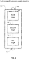
- FIG. 7 illustrates a second embodiment of a hot-swappable power supply module 700 that may be used in the system 600 of FIG. 6 .
- the hot-swappable power supply module 700 is configured to be inserted into and withdrawn from, for example, any of the slots 615 in the module rack 610 in a hot-swappable manner.
- the hot-swappable power supply module 700 includes an electrical input connector 710, a first power supply stage 720, a second power supply stage 730, a third power supply stage 740, and an electrical output connector 750.
- the third power supply stage 740 is an output power supply stage providing a dynamic waveform-controlled output signal.
- the dynamic waveform-controlled output signals generated by the third power supply stages 740 of the hot-swappable power supply modules 700 in a defined subset are synchronized and combined to generate a total welding or cutting electrical signal for welding or cutting.
- the electrical input connector 710 is configured to accept electrical input power (e.g., AC input power). In one embodiment, the electrical input connector 710 is also configured to accept one or more control signals from a controller (e.g., from the controller 620 via a backplane of the module rack 610). The one or more control signals control the operations of the first power supply stage 720, the second power supply stage 730, and the third power supply stage 740, in accordance with one embodiment.
- a controller e.g., from the controller 620 via a backplane of the module rack 610.
- the one or more control signals control the operations of the first power supply stage 720, the second power supply stage 730, and the third power supply stage 740, in accordance with one embodiment.
- U.S. Patent Application No. 2015/0014290 A1 which is incorporated by reference herein, describes various types of first (I), second (II), and third (III) power supply stages that are controlled by a controller.
- the electrical output connector 750 is configured to output a dynamic waveform-controlled output signal.
- the electrical output connector 750 is also configured to output one or more feedback signals to a controller (e.g., to the controller 620 via a backplane).
- the feedback signals may be derived from, for example, an output voltage and/or an output current of the module 700, in accordance with one embodiment, which are used by the controller 620 to modify the control signals.
- the feedback signals may also include module status signals. For example, a feedback signal may indicate when a particular module has failed (or has gone off-line).
- the controller can use the feedback information to report the failure to, for example, an external reporting system. As a result, a service call may be initiated to replace the failed module.
- the feedback signals are used to modify the control signals to synchronize the outputs (i.e., the dynamic waveform-controlled output signals) of all of the active power supply modules 700 within a subset. Synchronization may be achieved by adjusting the timing of the outputs of the modules 700 with respect to each other, for example.
- the synchronized outputs when combined, form a total welding or cutting electrical signal that supports generation of a single arc.
- the first power supply stage 720 is an AC to DC converter circuit.
- the second power supply stage 730 is an unregulated DC to DC converter circuit.
- the third power supply stage 740 includes a chopper circuit.
- the second power supply stage may include an inverter circuit with an isolation transformer and a rectifier circuit.
- the first power supply stage 720 accepts an electrical AC input signal, derived from the electrical input power to the module rack 610, at the electrical input connector 710.
- the second power supply stage 730 outputs an electrical DC signal to the third power supply stage 740.
- the third power supply stage 740 outputs a dynamic waveform-controlled output signal at the electrical output connector 750.
- Providing an electrical AC input to the module 700 is facilitated by a backplane of the module rack 610, in accordance with one embodiment. Also, synchronizing and combining the dynamic waveform-controlled output signals from the electrical output connectors 750 is facilitated by the backplane of the module rack 610, in accordance with one embodiment.
- a hot-swappable power supply module may have a single stage.
- a hot-swappable power supply module may have four stages. The numbers and types of stages depend on the design considerations and constraints associated with any particular application.
- each hot-swappable power supply module 700 provides 50 amps of electrical current. Therefore, a subset of such hot-swappable power supply modules 700 electrically connected in parallel can provide an electrical current of N x 50 amps, where N is the number of power supply modules 700 synchronized and connected in parallel. Therefore, depending on the current need for a particular welding or cutting operation, the controller 620 can select the number N of power supply modules 700 to be electrically connected and used for that operation. In accordance with other embodiments, each hot-swappable power supply module 700 provides some other amount of electrical current (e.g. 30 amps, or 60 amps, or 90 amps).
- some other amount of electrical current e.g. 30 amps, or 60 amps, or 90 amps.
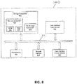
- FIG. 8 illustrates an embodiment of an example controller 800 that may be used as the controller 120, 320, 420, 520, or 620 respectively in the systems 100, 300, 400, 500, and 600 of FIG. 1 , FIG. 3 , FIG. 4 , FIG. 5 , and FIG. 6 .
- the controller 800 includes at least one processor 814 which communicates with a number of peripheral devices via bus subsystem 812. These peripheral devices may include a storage subsystem 824, including, for example, a memory subsystem 828 and a file storage subsystem 826, user interface input devices 822, user interface output devices 820, and a network interface subsystem 816.
- the input and output devices allow user interaction with the controller 800.
- Network interface subsystem 816 provides an interface to outside networks and is coupled to corresponding interface devices in other computer systems.
- the module rack 110 of the system 100 may share one or more characteristics with the controller 800 and may include, for example, elements of a conventional computer, a digital signal processor, and/or other computing device.
- User interface input devices 822 may include a keyboard, pointing devices such as a mouse, trackball, touchpad, or graphics tablet, a scanner, a touchscreen incorporated into the display, audio input devices such as voice recognition systems, microphones, and/or other types of input devices.
- pointing devices such as a mouse, trackball, touchpad, or graphics tablet
- audio input devices such as voice recognition systems, microphones, and/or other types of input devices.
- use of the term "input device” is intended to include all possible types of devices and ways to input information into the controller 800 or onto a communication network.
- User interface output devices 820 may include a display subsystem, a printer, a fax machine, or non-visual displays such as audio output devices.
- the display subsystem may include a cathode ray tube (CRT), a flat-panel device such as a liquid crystal display (LCD), a projection device, or some other mechanism for creating a visible image.
- the display subsystem may also provide non-visual display such as via audio output devices.
- output device is intended to include all possible types of devices and ways to output information from the controller 800 to the user or to another machine or computer system.
- Storage subsystem 824 stores programming and data constructs that provide some or all of the controller functionality described herein.
- the storage subsystem 824 may include one or more software modules including computer executable instructions for electrically connecting, in a hot-swappable manner, a power supply module that is newly inserted into a module rack without generating any electrical surges within the module rack and without generating any disturbances in a welding or cutting electrical signal during a welding or cutting operation.
- Memory subsystem 828 used in the storage subsystem can include a number of memories including a main random access memory (RAM) 830 for storage of instructions and data during program execution and a read only memory (ROM) 832 in which fixed instructions are stored.
- a file storage subsystem 826 can provide persistent storage for program and data files, and may include a hard disk drive, a floppy disk drive along with associated removable media, a CD-ROM drive, an optical drive, or removable media cartridges.
- the modules implementing the functionality of certain embodiments may be stored by file storage subsystem 826 in the storage subsystem 824, or in other machines accessible by the processor(s) 814.
- Bus subsystem 812 provides a mechanism for letting the various components and subsystems of the controller 800 communicate with each other as intended. Although bus subsystem 812 is shown schematically as a single bus, alternative embodiments of the bus subsystem may use multiple buses.
- the controller 800 can be of various implementations including a single computer, a single workstation, a computing cluster, a server computer, or any other data processing system or computing device configured to perform the controller functions described herein. Due to the ever-changing nature of computing devices and networks, the description of the controller 800 depicted in FIG. 8 is intended only as a specific example for purposes of illustrating some embodiments. Many other configurations of the controller 800 are possible having more or fewer components than the controller depicted in FIG. 8 .
- each individual power supply module that is connected in parallel is configured to produce an output that has voltage droop such that the current loads are balanced without requiring a master controller to balance the loads.
- the voltage droop is proportional to the load drawn such that when power supply modules are connected in parallel, the output current load is shared among the power supply modules.
- each individual power supply module is configured to ramp up an output gradually such that the other power supply modules individually compensate their loads without interfering with the total load. When one of the power supply modules attempts to provide more current, an output voltage of that power supply will droop and the other power supply modules that are in parallel will provide balance. In this manner, the controller is effectively distributed among the different power supply modules.
- power supply modules connected in parallel are configured to share the load current by trimming the no-load output voltage difference to be substantially less than the voltage droop at full load.
- power supply modules are configured to share the load current by increasing the output voltage droop of each power supply module such that the voltage droop at full load is substantially larger than the no-load voltage mismatch between modules.
- the output voltage droop is internally adjusted, for example, by adjusting an internal reference voltage based upon the load current.
- a reconfigurable modular power supply system provides redundancy, improved reliability, improved up-time, and improved serviceability across the welding or cutting environment. Such improvements are achieved by the implementation of multiple power supply modules (e.g., hot-swappable power supply modules) in a reconfigurable module rack.
- multiple power supply modules e.g., hot-swappable power supply modules
Landscapes
- Engineering & Computer Science (AREA)
- Physics & Mathematics (AREA)
- Plasma & Fusion (AREA)
- Mechanical Engineering (AREA)
- Theoretical Computer Science (AREA)
- Microelectronics & Electronic Packaging (AREA)
- Generation Of Surge Voltage And Current (AREA)
- Arc Welding Control (AREA)
Abstract
Embodiments of modular-based power supply systems (100) to support welding or cutting operations are disclosed. One embodiment, shown in Figure 1, includes a module rack (110) having multiple slots (115) configured to accept electrical input power from a single power drop within a welding or cutting environment. Multiple power supply modules are provided that are configured to be inserted into and withdrawn from the multiple slots (115). Each power supply module is configured to accept an electrical AC input derived from the electrical input power and provide an electrical DC output. The module rack (110) is configured to support reconfigurable parallel electrical connections of subsets of the power supply modules. Each subset is configured to electrically connect to an output power supply stage to provide a dynamic waveform-controlled welding or cutting electrical signal to support generation of a single arc between an electrode and a workpiece.
Description
-
U.S. Patent Application No. 2015/0014290 A1 entitled "Welding System and Method of Welding", filed on October 2, 2014, is incorporated herein by reference in its entirety. - The invention is related to a reconfigurable multi-arc system according to
claims 1 and 7 and to a reconfigurable system according to claim 14. Embodiments of the present invention relate to systems associated with a welding or cutting environment. More specifically, embodiments of the present invention relate to reconfigurable systems for generating one or more arcs for welding or cutting. - In a welding or cutting environment (e.g., in a factory environment where welding or cutting is performed), many welding or cutting power supplies may be located at various locations within the welding or cutting environment to support various welding or cutting operations throughout the environment. When a power supply has a problem and shuts down, the corresponding welding or cutting operation is also shut down until the problem can be resolved. The ability to have a power supply configuration that allows the corresponding welding or cutting operation to continue, even while the problem is being resolved, is desirable.
- In order to improve welding, especially at various locations, a reconfigurable multi-arc system according to
claims 1 and 7 is described and a reconfigurable system according to claim 14. Preferred embodiments are subject of the subclaims. Embodiments of the present invention include systems to support the generation of one or more (multiple) arcs for welding or plasma cutting in a welding or cutting environment (e.g., a factory). A reconfigurable modular power supply system provides redundancy, improved reliability, improved up-time, and improved serviceability across the welding or cutting environment. Such improvements are achieved by the implementation of hot-swappable power supply modules in a reconfigurable module rack. As used herein, power supply modules that are hot-swappable are power supply modules that can be removed from and inserted into a module rack without stopping or shutting down the associated welding or cutting system (i.e., without interruption to the on-going welding or cutting operation). Hot-swapping can be achieved by rack and module design particulars as well as by employing a controller implementing hot-swapping control techniques, as discussed later herein. - One embodiment includes a system to support the generation of multiple arcs for welding or cutting within a welding or cutting environment. The system includes a module rack having a plurality of module slots. The module rack is configured to accept electrical input power from a single power drop within the welding or cutting environment via a power disconnect box. The system also includes a plurality of power supply modules (e.g., hot-swappable power supply modules) configured to be respectively inserted into and withdrawn from the plurality of module slots. Each power supply module is configured to accept an electrical AC input derived from the electrical input power and provide an electrical DC output. The module rack is configured to support reconfigurable parallel electrical connections of subsets of the power supply modules inserted into the module rack. The system further includes a plurality of output power supply stages. An electrical input of each output power supply stage is configured to connect to an electrical output of a separate subset of the subsets of the power supply modules. Each output power supply stage is configured to provide a dynamic waveform-controlled welding or cutting electrical signal to support the generation of a single arc, of the multiple arcs, between an electrode and a workpiece for welding or cutting. The system also includes a controller operatively interfacing to the module rack, in one embodiment. The controller is configured to define and electrically connect in parallel a first subset of the power supply modules within the module rack. The controller is also configured to electrically connect a newly inserted power supply module into the first subset while avoiding generating electrical surges within the module rack, and while avoiding generating disturbances in a first welding or cutting electrical signal associated with the first subset during a first welding or cutting operation. In one embodiment, each power supply module includes a first power supply stage and a second power supply stage. In one embodiment, each power supply module includes an AC to DC converter circuit. In one embodiment, each power supply module includes an unregulated DC to DC converter circuit. In one embodiment, each power supply module includes an inverter circuit with an isolation transformer and a rectifier circuit. In one embodiment, each output power supply stage includes a chopper circuit. In one embodiment, each output power supply stage is configured to be located remotely from the module rack and be electrically connected to the module rack via an electrical cable. In another embodiment, each output power supply stage is configured to be located within the module rack.
- One embodiment includes a system to support the generation of multiple arcs for welding or cutting within a welding or cutting environment. The system includes a module rack having a plurality of module slots. The module rack is configured to accept electrical input power from a single power drop within the welding or cutting environment via a power disconnect box. The system also includes a plurality of power supply modules (e.g., hot-swappable power supply modules) configured to be respectively inserted into and withdrawn from the plurality of module slots. Each power supply module is configured to accept an electrical AC input derived from the electrical input power and provide an electrical DC output. Each power supply module is also configured to provide a dynamic waveform-controlled output signal. The module rack is configured to support reconfigurable parallel electrical connections of subsets of the power supply modules inserted into the module rack. The system also includes a controller operatively interfacing to the module rack and configured to synchronize the dynamic waveform-controlled output signal of each power supply module, within each subset, with each other to provide a welding or cutting electrical signal from each subset. Synchronization of the dynamic waveform-controlled output signals of each subset is based on feedback information from each corresponding subset, in accordance with one embodiment. The welding or cutting electrical signal from each subset supports generation of a single arc, of the multiple arcs, between an electrode and a workpiece for welding or cutting. In one embodiment, the controller is configured to define and electrically connect in parallel a first subset of the power supply modules within the module rack. The controller is also configured to electrically connect a newly inserted power supply module into the first subset while avoiding generating electrical surges within the module rack, and while avoiding generating disturbances in a first welding or cutting electrical signal associated with the first subset during a first welding or cutting operation. In one embodiment, the controller is configured to report a failure of a power supply module to an external reporting system. In one embodiment, each power supply module includes a first power supply stage, a second power supply stage, and a third power supply stage. In one embodiment, each power supply module includes an AC to DC converter circuit. In one embodiment, each power supply module includes an unregulated DC to DC converter circuit. In one embodiment, each power supply module includes an inverter circuit with an isolation transformer and a rectifier circuit. In one embodiment, each power supply module includes a chopper circuit.
- One embodiment includes a system to support the generation of at least one arc for welding or cutting within a welding or cutting environment. The system includes a module rack having a plurality of module slots. The module rack is configured to accept electrical input power from a single power drop within a welding or cutting environment via a power disconnect box. The system includes a plurality of power supply modules (e.g., hot-swappable power supply modules) configured to be respectively inserted into and withdrawn from the plurality of module slots. The module rack is configured to support reconfigurable parallel electrical connections of the plurality of power supply modules inserted into the module rack. The system further includes a controller configured to electrically connect a newly replaced power supply module within the module rack while avoiding generating electrical surges within the module rack, and while avoiding generating disturbances in a welding or cutting electrical signal supported by the module rack during a welding or cutting operation. In one embodiment, the controller is configured to report a failure of a power supply module to an external reporting system.
- Numerous aspects of the general inventive concepts will become readily apparent from the following detailed description of exemplary embodiments, from the claims, and from the accompanying drawings.
- The accompanying drawings, which are incorporated in and constitute a part of the specification, illustrate various embodiments of the disclosure. It will be appreciated that the illustrated element boundaries (e.g., boxes, groups of boxes, or other shapes) in the figures represent one embodiment of boundaries. In some embodiments, one element may be designed as multiple elements or that multiple elements may be designed as one element. In some embodiments, an element shown as an internal component of another element may be implemented as an external component and vice versa. Furthermore, elements may not be drawn to scale.
-
FIG. 1 illustrates a first embodiment of a reconfigurable multi-arc system to support the generation of multiple arcs for welding or cutting in a welding or cutting environment; -
FIG. 2 illustrates a first embodiment of a power supply module (e.g., a hot-swappable power supply module) that may be used in the systems ofFIG. 1 ,FIG. 3 ,FIG. 4 , orFIG. 5 ; -
FIG. 3 illustrates a second embodiment of a reconfigurable multi-arc system to support the generation of multiple arcs for welding or cutting in a welding or cutting environment; -
FIG. 4 illustrates a first embodiment of a reconfigurable single-arc system to support the generation of a single arc for welding or cutting in a welding or cutting environment; -
FIG. 5 illustrates a second embodiment of a reconfigurable single-arc system to support the generation of a single arc for welding or cutting in a welding or cutting environment; -
FIG. 6 illustrates a third embodiment of a reconfigurable multi-arc system to support the generation of multiple arcs for welding or cutting in a welding or cutting environment; -
FIG. 7 illustrates a second embodiment of a power supply module (e.g., a hot-swappable power supply module) that may be used in the system ofFIG. 6 ; and -
FIG. 8 illustrates one embodiment of an example controller that may be used as the controller in the systems ofFIG. 1 ,FIG. 3 ,FIG. 4 ,FIG. 5 , andFIG. 6 . - Embodiments of reconfigurable systems to support the generation of one or more arcs for welding or cutting in a welding or cutting environment are disclosed. In one embodiment, a reconfigurable multi-arc system is disclosed. The reconfigurable multi-arc system includes a module rack and multiple power supply modules (e.g., hot-swappable power supply modules) organized within the module rack to support the generation of multiple arcs for welding or cutting within a welding or cutting environment.
- The examples and figures herein are illustrative only and are not meant to limit the subject invention, which is measured by the scope and spirit of the claims. Referring now to the drawings, wherein the showings are for the purpose of illustrating exemplary embodiments of the subject invention only and not for the purpose of limiting same,
FIG. 1 illustrates a first embodiment of a reconfigurablemulti-arc system 100 to support the generation of multiple arcs for welding or plasma cutting in a welding or cutting environment. - Referring to
FIG. 1 , the reconfigurablemulti-arc system 100 includes amodule rack 110 havingmultiple module slots 115. Eachmodule slot 115 is configured to have a power supply module inserted into and withdrawn from a slot in a hot-swappable manner. The power supply modules can support one or more welding or cutting operations. The power supply modules are hot-swappable and can be removed from and inserted into themodule rack 110 without stopping or shutting down the associated welding or cutting system (i.e., without interruption to an on-going welding or cutting operation). Hot-swapping can be achieved by rack and module design particulars as well as by employing a controller implementing hot-swapping control techniques. An embodiment of a power supply module is discussed later herein with respect toFIG. 2 . In another embodiment, the power supply modules are not hot-swappable. - In accordance with one embodiment, the
module rack 110 includes wiring and/or traces and controllable switches that support reconfigurable electrical connections of the power supply modules. For example, themodule rack 110 may include a reconfigurable backplane that allows various combinations or subsets of power supply modules to be electrically connected to each other. The reconfigurable backplane may be under the control of a programmable controller, for example, in accordance with one embodiment. Furthermore, in one embodiment, themodule rack 110 is configured to accept electrical input power (e.g., 460 VAC) from a single power drop within a welding or cutting environment via, for example, a power disconnect box having, for example, switches and fuses. Electrical power distributed to the inputs of individual power supply modules within themodule rack 110 is derived from the electrical input power (e.g., under the control of a controller). - The
system 100 includes acontroller 120 operatively interfacing to themodule rack 110. In one embodiment, thecontroller 120 is configured to define subsets of the power supply modules within themodule rack 110. Thecontroller 120 is also configured to command electrical connection of a defined subset of the power supply modules in parallel via the module rack (e.g. by reconfiguring a backplane of the module rack 110). Such a subset of power supply modules can be used in a welding or cutting operation to support generation of a single arc between an electrode and a workpiece for welding or cutting in a welding or cutting environment. In such an embodiment, thecontroller 120 provides flexibility in defining a subset of power supply modules within themodule rack 110 to be electrically connected together in parallel. In the extreme, a subset can include a single power supply module. Redundancy can be provided by having the total power supplied by the multiple power supply modules within themodule rack 110 be more than the total output power requirement from themodule rack 110. Furthermore, in accordance with one embodiment, thecontroller 120 is configured to reduce the output power when some of the power supply modules are down. - The
controller 120 is also configured to electrically connect a newly inserted hot-swappable power supply module into a subset while avoiding generating electrical surges within themodule rack 110, and while avoiding generating disturbances in a welding or cutting electrical signal associated with the subset during a welding or cutting operation. In accordance with one embodiment, thecontroller 120 can avoid the occurrence of such surges and disturbances by bringing a newly inserted power supply module on-line slowly (e.g., by slowly powering up the newly inserted power supply module) and/or by electrically connecting various input and output pins of the newly inserted power supply module in a particular order. The controller is configured to balance the power draw from each module by ramping up the power of a newly inserted module and ramping down the power of existing on-line modules, in accordance with one embodiment. - In another embodiment, the subsets of power supply modules are defined largely by the
module rack 110. For example, referring toFIG. 1 , five (5) rows ofslots 115 are shown within themodule rack 110 which can be populated with hot-swappable power supply modules. The first row defines a first subset corresponding to up to ten (10) modules. Similarly, the second through fifth rows each define subsets corresponding to, respectively, up to ten (10), nine (9), eight (8), and seven (7) modules. In such an embodiment, thecontroller 120 is still used to support hot-swapping of the power supply modules to avoid surges and disturbances. - As shown in
FIG. 1 , each subset (row) ofslots 115, which may be populated with hot-swappable power supply modules, can be electrically connected to achopper circuit 130 serving as an output power supply stage. Other types of output power supply stages (other than a chopper circuit) are possible as well, in accordance with other embodiments. An electrical input of each outputpower supply stage 130 is configured to be connected to an electrical output of a separate subset of the hot-swappable power supply modules that are connected in parallel. - Each output
power supply stage 130 provides a dynamic waveform-controlled welding or cutting signal to support generation of a single arc between an electrode and a workpiece for welding or cutting. For example, a dynamic waveform-controlled welding or cutting signal from an outputpower supply stage 130 may be provided to a welding gun/torch and/or welding wire feeder within a welding or cutting environment. In this manner, thesystem 100 ofFIG. 1 provides the dynamic welding or cutting voltages and currents to support various welding or cutting operations and modes. In accordance with one embodiment, each output power supply stage 130 (e.g., chopper circuit) is under the control of a separate controller and/or a waveform generator.U.S. Patent Application No. 2015/0014290 A1 , which is incorporated by reference herein, describes various configurations of output power supply stages that are controlled by a controller and/or a waveform generator. -
FIG. 2 illustrates a first embodiment of a hot-swappablepower supply module 200 that may be used in thesystems FIG. 1 ,FIG. 3 ,FIG. 4 , andFIG. 5 , respectively. The hot-swappablepower supply module 200 is configured to be inserted into and withdrawn from, for example, any of theslots 115 in themodule rack 110 in a hot-swappable manner. The hot-swappablepower supply module 200 includes anelectrical input connector 210, a firstpower supply stage 220, a secondpower supply stage 230, and anelectrical output connector 240. - The
electrical input connector 210 is configured to accept electrical input power (e.g., AC input power). In one embodiment, theelectrical input connector 210 is also configured to accept one or more control signals from a controller (e.g., from thecontroller 120 via a backplane of the module rack 110). The one or more control signals control the operations of the firstpower supply stage 220 and the secondpower supply stage 230, in accordance with one embodiment.U.S. Patent Application No. 2015/0014290 A1 , which is incorporated by reference herein, describes various types of first (I) and second (II) power supply stages that are controlled by a controller. Theelectrical output connector 240 is configured to output an unregulated electrical DC signal. In one embodiment, theelectrical output connector 240 is also configured to output one or more feedback signals to a controller (e.g., to thecontroller 120 via a backplane of the module rack 110). The feedback signals may be derived from, for example, an output voltage and/or an output current of themodule 200, in accordance with one embodiment, which are used by thecontroller 120 to modify the control signals. - The feedback signals can also include module status signals. For example, a feedback signal can indicate when a particular module has failed (or has gone off-line). The controller can use the feedback information to report the failure to, for example, an external reporting system. As a result, a service call can be initiated to replace the failed module. Furthermore, the controller can use the feedback information to take the failed module off-line and bring another module on-line in its place within the associated subset of modules. In this manner, the operation (e.g., power, waveform, timing) and the status (e.g., failed module) of each power supply module can be monitored and controlled, and power supply modules can be taken off-line and brought on-line in a real-time, dynamic manner.
- In one embodiment, the first
power supply stage 220 is an AC to DC converter circuit. The secondpower supply stage 230 is an unregulated DC to DC converter circuit. For example, in one embodiment, the secondpower supply stage 230 may include an inverter circuit with an isolation transformer and a rectifier circuit. The firstpower supply stage 220 accepts an electrical AC input signal, derived from the electrical input power to themodule rack 110, at theelectrical input connector 210. The secondpower supply stage 230 outputs an electrical DC output signal at theelectrical output connector 240. Providing an electrical AC input to themodule 200 is facilitated by a backplane of themodule rack 110, in accordance with one embodiment. Also, routing the electrical DC output signal away from theelectrical output connector 240 is facilitated by the backplane of themodule rack 110, in accordance with one embodiment. In accordance with one embodiment, The AC to DC converter circuit of the firstpower supply stage 220 is configured to provide a power factor correction function. -
U.S. Patent Application No. 2015/0014290 A1 , which is incorporated by reference herein, describes various types of first (I) and second (II) power supply stages. Other types of hot-swappable power supply modules are possible as well, in accordance with other embodiments. For example, in one embodiment, a hot-swappable power supply module may have a single stage. In another embodiment, a hot-swappable power supply module may have three stages. The numbers and types of stages depend on the design considerations and constraints associated with any particular application. - In accordance with one embodiment, each hot-swappable
power supply module 200 provides 50 amps of electrical current. Therefore, a subset of such hot-swappablepower supply modules 200 electrically connected in parallel can provide an electrical current of N x 50 amps, where N is the number ofpower supply modules 200 connected in parallel. Therefore, depending on the current need for a particular welding or cutting operation, thecontroller 120 can select the number N ofpower supply modules 200 to be electrically connected and used for that operation. In accordance with other embodiments, each hot-swappablepower supply module 200 provides some other amount of electrical current (e.g. 25 amps, or 75 amps, or 100 amps). - In the embodiment of
FIG. 1 , each output power supply stage 130 (e.g., a chopper circuit) is external to themodule rack 110. For example, in accordance with one embodiment, themodule rack 110 is centrally located within a welding or cutting environment, accepting electrical input power from a single power drop via a power disconnect box. Eachchopper circuit 130 is located remotely from themodule rack 110 at a robotic welding or cutting station within the welding or cutting environment and is electrically connected to themodule rack 110 via electrical cables. In this way, asingle module rack 110 can support the generation of multiple welding or cutting arcs throughout the welding or cutting environment. The DC outputs out of themodule rack 110 are not affected by the inductance of the electrical cables connecting themodule rack 110 to thevarious chopper circuits 130 at the welding or cutting stations. Therefore, fairly long cable lengths can be accommodated across a welding or cutting environment. -
FIG. 3 illustrates a second embodiment of a reconfigurablemulti-arc system 300 to support the generation of multiple arcs for welding or cutting in a welding or cutting environment. Thesystem 300 ofFig. 3 is similar to thesystem 100 ofFig. 1 in that thesystem 300 includes amodule rack 310 having module slots 315 (similar to themodule slots 115 to accept the modules 200), a controller 320 (similar to the controller 120), and output power supply stages (e.g., chopper circuits) 330 (similar to the output power supply stages 130). However, in thesystem 300 ofFIG. 3 , the output power supply stages (e.g., chopper circuits) 330 are located within themodule rack 310, not externally to themodule rack 310. In one embodiment, thecontroller 320 can determine whichchopper circuit 330 to connect to which subset of hot-swappable power supply modules via, for example, a backplane of themodule rack 310. Furthermore, in accordance with one embodiment, thecontroller 320 also controls the operation of each of the output power supply stages 330. In accordance with another embodiment, each outputpower supply stage 330 may be controlled by a dedicated controller within themodule rack 310. Thesystem 300 ofFIG. 3 may be desirable when used in a welding or cutting environment that is relatively small, mitigating the use of long cable lengths to the welding or cutting stations. -
FIG. 4 illustrates a first embodiment of a reconfigurable single-arc system 400 to support the generation of a single arc for welding or cutting in a welding or cutting environment. Thesystem 400 includes amodule rack 410 havingmodule slots 415 to accommodate hot-swappable power supply modules (e.g., 200). The system also includes acontroller 420 and an output power supply stage (e.g., a chopper circuit) 430. Thesystem 400 is similar to a portion of thesystem 100 ofFIG. 1 . For example, themodule rack 410 may be equivalent to the first row of themodule rack 110 inFIG. 1 . Thechopper circuit 430 may be equivalent to thechopper # 1 130 inFIG. 1 . Thecontroller 420 may be somewhat similar to thecontroller 120 inFIG. 1 . However, in thesystem 400 ofFIG. 4 , only the generation of a single arc is supported (e.g., at a robotic welding or cutting work station or at a manual welding or cutting work station) within a welding or cutting environment. - In the embodiment of
Fig. 4 , thecontroller 420 determines which power supply modules to use to provide an electrical input to thechopper circuit 430. Thecontroller 420 also allows the power supply modules to be replaced in theslots 415 in a hot-swappable manner. Furthermore, in accordance with one embodiment, thecontroller 420 controls the operation of thechopper circuit 430. For example, in one embodiment, thecontroller 420 includes a waveform generator to facilitate the generation of a dynamic waveform-controlled welding or cutting electrical signal by thechopper circuit 430. Examples of controlling a chopper circuit via a waveform generator are disclosed inU.S. Patent Application No. 2015/0014290 A1 , which is incorporated by reference herein. In this manner, a smaller module rack can be provided to support a single arc operation. Also, the DC output out of themodule rack 410 is not affected by the inductance of the electrical cable connecting themodule rack 410 to thechopper circuit 430 at the welding or cutting station. Therefore, a fairly long cable length can be accommodated. -
FIG. 5 illustrates a second embodiment of a reconfigurable single-arc system 500 to support the generation of a single arc for welding or cutting in a welding or cutting environment. Thesystem 500 is similar to thesystem 400 ofFIG. 4 in that thesystem 500 includes amodule rack 510 having module slots 515 (similar to themodule slots 415 to accept the modules 200), a controller 520 (similar to the controller 420), and an output power supply stage (e.g., a chopper circuit) 530 (similar to the output power supply stage 430). However, in thesystem 500 ofFIG. 5 , the output power supply stage (e.g., the chopper circuit) 530 is located within themodule rack 510, not externally to themodule rack 510. In one embodiment, thecontroller 520 determines which power supply modules to use to provide an electrical input to thechopper circuit 530. Thecontroller 520 also allows the power supply modules to be replaced in theslots 515 in a hot-swappable manner. Furthermore, in accordance with one embodiment, thecontroller 520 controls the operation of thechopper circuit 530. Thesystem 500 ofFIG. 5 may be desirable when used in a welding or cutting environment that is relatively small, mitigating the use of a long cable length to the welding or cutting station. In this manner, a smaller module rack can be provided to support a single arc operation. -
FIG. 6 illustrates a third embodiment of a reconfigurablemulti-arc system 600 to support the generation of multiple arcs for welding or cutting in a welding or cutting environment. In the embodiment ofFIG. 6 , an output power supply stage is part of each hot-swappable power supply module. The dynamic waveform-controlled output signals generated by the output power supply stages of the hot-swappable power supply modules in a defined subset are synchronized and combined to generate a total welding or cutting electrical signal for welding or cutting. - The reconfigurable
multi-arc system 600 includes amodule rack 610 havingmultiple module slots 615. Eachmodule slot 615 is configured to have a power supply module (which includes an output power supply stage) inserted into and withdrawn from a slot in a hot-swappable manner. The power supply modules can support one or more welding or cutting operations. The power supply modules are hot-swappable and can be removed from and inserted into themodule rack 610 without stopping or shutting down the associated welding or cutting system (i.e., without interruption to an on-going welding or cutting operation). Hot-swapping can be achieved by rack and module design particulars as well as by employing a controller implementing hot-swapping control techniques. An embodiment of a power supply module is discussed later herein with respect toFIG. 7 . - In accordance with one embodiment, the
module rack 610 includes wiring and/or traces and controllable switches that support reconfigurable electrical connections of the power supply modules. For example, themodule rack 610 may include a reconfigurable backplane that allows various combinations or subsets of power supply modules to be electrically connected to each other. The reconfigurable backplane may be under the control of a programmable controller, for example. Furthermore, in one embodiment, themodule rack 610 is configured to accept electrical input power (e.g., 460 VAC) from a single power drop within a welding or cutting environment via, for example, a power disconnect box having, for example, switches and fuses. Electrical power distributed to the inputs of individual power supply modules within themodule rack 610 is derived from the electrical input power (e.g., under the control of a controller). - The
system 600 includes acontroller 620 operatively interfacing to themodule rack 610. In one embodiment, thecontroller 620 is configured to define subsets of the power supply modules within themodule rack 610. Thecontroller 620 is also configured to command electrical connection of a defined subset of the power supply modules in parallel via the module rack 610 (e.g. by reconfiguring a backplane of the module rack 610). Such a subset of power supply modules can be used in a welding or cutting operation to support generation of a single arc between an electrode and a workpiece for welding or cutting in a welding or cutting environment. In such an embodiment, thecontroller 620 provides flexibility in defining a subset of power supply modules within themodule rack 610 to be electrically connected together in parallel. - Each power supply module is configured to output a dynamic waveform-controlled output signal, in accordance with one embodiment. For a subset of the power supply modules, the
controller 620 is configured to not only electrically connect the power supply modules in the subset together in parallel, but also to synchronize the dynamic waveform-controlled output signals of all the power supply modules in the subset to provide a total welding or cutting electrical signal that supports generation of an arc for welding or cutting. Details of the synchronization are discussed later herein with respect toFIG. 7 . - The
controller 620 is also configured to electrically connect a newly inserted hot-swappable power supply module into a subset while avoiding generating electrical surges within themodule rack 610, and while avoiding generating disturbances in a welding or cutting electrical signal associated with the subset during a welding or cutting operation. In accordance with one embodiment, thecontroller 620 can avoid the occurrence of such surges and disturbances by bringing a newly inserted power supply module on-line slowly (e.g., by slowly powering up the newly inserted power supply module) and/or by electrically connecting various input and output pins of the newly inserted power supply module in a particular order. - In another embodiment, the subsets of power supply modules are defined largely by the
module rack 610. For example, referring toFIG. 6 , five (5) rows ofslots 615 are shown within themodule rack 610 which can be populated with hot-swappable power supply modules. The first row defines a first subset corresponding to up to ten (10) modules. Similarly, the second through fifth rows each define subsets corresponding to, respectively, up to ten (10), nine (9), eight (8), and seven (7) modules. In such an embodiment, thecontroller 620 is still used to support hot-swapping of the power supply modules to avoid surges and disturbances. - Each hot-swappable power supply module provides a dynamic waveform-controlled output signal. The outputs of the hot-swappable power supply modules within a defined subset are synchronized and electrically connected in parallel to form a total welding or cutting electrical signal to support generation of a single arc between an electrode and a workpiece for welding or cutting. For example, a total welding or cutting electrical signal from a subset of synchronized modules may be provided to a welding gun/torch and/or welding wire feeder within a welding or cutting environment. In this manner, the
system 600 ofFIG. 6 provides the dynamic welding or cutting voltages and currents to support various welding or cutting operations and modes. In accordance with one embodiment, each defined subset of power supply modules is under the control of thecontroller 620 to perform waveform generation. -
FIG. 7 illustrates a second embodiment of a hot-swappablepower supply module 700 that may be used in thesystem 600 ofFIG. 6 . The hot-swappablepower supply module 700 is configured to be inserted into and withdrawn from, for example, any of theslots 615 in themodule rack 610 in a hot-swappable manner. The hot-swappablepower supply module 700 includes anelectrical input connector 710, a firstpower supply stage 720, a secondpower supply stage 730, a thirdpower supply stage 740, and anelectrical output connector 750. In the embodiment ofFIG. 7 , the thirdpower supply stage 740 is an output power supply stage providing a dynamic waveform-controlled output signal. The dynamic waveform-controlled output signals generated by the third power supply stages 740 of the hot-swappablepower supply modules 700 in a defined subset are synchronized and combined to generate a total welding or cutting electrical signal for welding or cutting. - The
electrical input connector 710 is configured to accept electrical input power (e.g., AC input power). In one embodiment, theelectrical input connector 710 is also configured to accept one or more control signals from a controller (e.g., from thecontroller 620 via a backplane of the module rack 610). The one or more control signals control the operations of the firstpower supply stage 720, the secondpower supply stage 730, and the thirdpower supply stage 740, in accordance with one embodiment.U.S. Patent Application No. 2015/0014290 A1 , which is incorporated by reference herein, describes various types of first (I), second (II), and third (III) power supply stages that are controlled by a controller. - The
electrical output connector 750 is configured to output a dynamic waveform-controlled output signal. In one embodiment, theelectrical output connector 750 is also configured to output one or more feedback signals to a controller (e.g., to thecontroller 620 via a backplane). The feedback signals may be derived from, for example, an output voltage and/or an output current of themodule 700, in accordance with one embodiment, which are used by thecontroller 620 to modify the control signals. The feedback signals may also include module status signals. For example, a feedback signal may indicate when a particular module has failed (or has gone off-line). The controller can use the feedback information to report the failure to, for example, an external reporting system. As a result, a service call may be initiated to replace the failed module. In this manner, operation (e.g., power, waveform, timing) and status (e.g., failed module) of each power supply module can be monitored and controlled. Furthermore, in accordance with one embodiment, the feedback signals are used to modify the control signals to synchronize the outputs (i.e., the dynamic waveform-controlled output signals) of all of the activepower supply modules 700 within a subset. Synchronization may be achieved by adjusting the timing of the outputs of themodules 700 with respect to each other, for example. The synchronized outputs, when combined, form a total welding or cutting electrical signal that supports generation of a single arc. - In one embodiment, the first
power supply stage 720 is an AC to DC converter circuit. The secondpower supply stage 730 is an unregulated DC to DC converter circuit. The thirdpower supply stage 740 includes a chopper circuit. For example, in one embodiment, the second power supply stage may include an inverter circuit with an isolation transformer and a rectifier circuit. The firstpower supply stage 720 accepts an electrical AC input signal, derived from the electrical input power to themodule rack 610, at theelectrical input connector 710. The secondpower supply stage 730 outputs an electrical DC signal to the thirdpower supply stage 740. The thirdpower supply stage 740 outputs a dynamic waveform-controlled output signal at theelectrical output connector 750. Providing an electrical AC input to themodule 700 is facilitated by a backplane of themodule rack 610, in accordance with one embodiment. Also, synchronizing and combining the dynamic waveform-controlled output signals from theelectrical output connectors 750 is facilitated by the backplane of themodule rack 610, in accordance with one embodiment. -
U.S. Patent Application No. 2015/0014290 A1 , which is incorporated by reference herein, describes various types of first (I), second (II), and third (III) power supply stages. Other types of hot-swappable power supply modules are possible as well, in accordance with other embodiments. For example, in one embodiment, a hot-swappable power supply module may have a single stage. In another embodiment, a hot-swappable power supply module may have four stages. The numbers and types of stages depend on the design considerations and constraints associated with any particular application. - In accordance with one embodiment, each hot-swappable
power supply module 700 provides 50 amps of electrical current. Therefore, a subset of such hot-swappablepower supply modules 700 electrically connected in parallel can provide an electrical current of N x 50 amps, where N is the number ofpower supply modules 700 synchronized and connected in parallel. Therefore, depending on the current need for a particular welding or cutting operation, thecontroller 620 can select the number N ofpower supply modules 700 to be electrically connected and used for that operation. In accordance with other embodiments, each hot-swappablepower supply module 700 provides some other amount of electrical current (e.g. 30 amps, or 60 amps, or 90 amps). -
FIG. 8 illustrates an embodiment of anexample controller 800 that may be used as thecontroller systems FIG. 1 ,FIG. 3 ,FIG. 4 ,FIG. 5 , andFIG. 6 . Thecontroller 800 includes at least oneprocessor 814 which communicates with a number of peripheral devices viabus subsystem 812. These peripheral devices may include astorage subsystem 824, including, for example, amemory subsystem 828 and afile storage subsystem 826, user interface input devices 822, user interface output devices 820, and anetwork interface subsystem 816. The input and output devices allow user interaction with thecontroller 800.Network interface subsystem 816 provides an interface to outside networks and is coupled to corresponding interface devices in other computer systems. For example, themodule rack 110 of thesystem 100 may share one or more characteristics with thecontroller 800 and may include, for example, elements of a conventional computer, a digital signal processor, and/or other computing device. - User interface input devices 822 may include a keyboard, pointing devices such as a mouse, trackball, touchpad, or graphics tablet, a scanner, a touchscreen incorporated into the display, audio input devices such as voice recognition systems, microphones, and/or other types of input devices. In general, use of the term "input device" is intended to include all possible types of devices and ways to input information into the
controller 800 or onto a communication network. - User interface output devices 820 may include a display subsystem, a printer, a fax machine, or non-visual displays such as audio output devices. The display subsystem may include a cathode ray tube (CRT), a flat-panel device such as a liquid crystal display (LCD), a projection device, or some other mechanism for creating a visible image. The display subsystem may also provide non-visual display such as via audio output devices. In general, use of the term "output device" is intended to include all possible types of devices and ways to output information from the
controller 800 to the user or to another machine or computer system. -
Storage subsystem 824 stores programming and data constructs that provide some or all of the controller functionality described herein. For example, thestorage subsystem 824 may include one or more software modules including computer executable instructions for electrically connecting, in a hot-swappable manner, a power supply module that is newly inserted into a module rack without generating any electrical surges within the module rack and without generating any disturbances in a welding or cutting electrical signal during a welding or cutting operation. - These software modules are generally executed by
processor 814 alone or in combination with other processors.Memory subsystem 828 used in the storage subsystem can include a number of memories including a main random access memory (RAM) 830 for storage of instructions and data during program execution and a read only memory (ROM) 832 in which fixed instructions are stored. Afile storage subsystem 826 can provide persistent storage for program and data files, and may include a hard disk drive, a floppy disk drive along with associated removable media, a CD-ROM drive, an optical drive, or removable media cartridges. The modules implementing the functionality of certain embodiments may be stored byfile storage subsystem 826 in thestorage subsystem 824, or in other machines accessible by the processor(s) 814. -
Bus subsystem 812 provides a mechanism for letting the various components and subsystems of thecontroller 800 communicate with each other as intended. Althoughbus subsystem 812 is shown schematically as a single bus, alternative embodiments of the bus subsystem may use multiple buses. - The
controller 800 can be of various implementations including a single computer, a single workstation, a computing cluster, a server computer, or any other data processing system or computing device configured to perform the controller functions described herein. Due to the ever-changing nature of computing devices and networks, the description of thecontroller 800 depicted inFIG. 8 is intended only as a specific example for purposes of illustrating some embodiments. Many other configurations of thecontroller 800 are possible having more or fewer components than the controller depicted inFIG. 8 . - In accordance with one embodiment, each individual power supply module that is connected in parallel is configured to produce an output that has voltage droop such that the current loads are balanced without requiring a master controller to balance the loads. The voltage droop is proportional to the load drawn such that when power supply modules are connected in parallel, the output current load is shared among the power supply modules. Furthermore, each individual power supply module is configured to ramp up an output gradually such that the other power supply modules individually compensate their loads without interfering with the total load. When one of the power supply modules attempts to provide more current, an output voltage of that power supply will droop and the other power supply modules that are in parallel will provide balance. In this manner, the controller is effectively distributed among the different power supply modules.
- For example, in accordance with one embodiment, power supply modules connected in parallel are configured to share the load current by trimming the no-load output voltage difference to be substantially less than the voltage droop at full load. In another embodiment, power supply modules are configured to share the load current by increasing the output voltage droop of each power supply module such that the voltage droop at full load is substantially larger than the no-load voltage mismatch between modules. The output voltage droop is internally adjusted, for example, by adjusting an internal reference voltage based upon the load current.
- In summary, a reconfigurable modular power supply system provides redundancy, improved reliability, improved up-time, and improved serviceability across the welding or cutting environment. Such improvements are achieved by the implementation of multiple power supply modules (e.g., hot-swappable power supply modules) in a reconfigurable module rack.
- While the disclosed embodiments have been illustrated and described in considerable detail, it is not the intention to restrict or in any way limit the scope of the appended claims to such detail. It is, of course, not possible to describe every conceivable combination of components or methodologies for purposes of describing the various aspects of the subject matter. Therefore, the disclosure is not limited to the specific details or illustrative examples shown and described. Thus, this disclosure is intended to embrace alterations, modifications, and variations that fall within the scope of the appended claims, which satisfy the statutory subject matter requirements of 35 U.S.C. §101. The above description of specific embodiments has been given by way of example. From the disclosure given, those skilled in the art will not only understand the general inventive concepts and attendant advantages, but will also find apparent various changes and modifications to the structures and methods disclosed. It is sought, therefore, to cover all such changes and modifications as fall within the spirit and scope of the general inventive concepts, as defined by the appended claims, and equivalents thereof.
REFERENCE NUMBERS 515 module slot 520 controller 100 multi-arc system 530 power supply stage // chopper circuit 110 module rack 115 module slot 600 multi-arc system 120 controller 610 module rack 130 chopper circuit // power supply stage 615 module slot 620 controller 200 power supply module 700 power supply module 210 input connector 710 input connector 220 first power supply stage 720 first power supply stage 230 second power supply stage 730 second power supply stage 240 output connector 740 third power supply stage 300 multi-arc system 750 output connector 310 module rack 800 controller 315 module slot 812 bus subsystem 320 controller 814 processor 330 power supply stage 816 network interface subsyystem 400 single-arc system 820 user interface output device 410 module rack 822 user interface input device 415 module slot 824 storage subsystem 420 controller 826 file storage subsystem 430 power supply stage // chopper circuit 828 memory subsystem 500 single- arc system 830 random access memory 510 module rack 832 read-only memory
Claims (15)
- A reconfigurable multi-arc system (100, 300, 600) to support generation of multiple arcs for welding or cutting, the system comprising:a module rack (110, 310, 610) having a plurality of module slots (115, 315, 615) and being configured to accept electrical input power from a single power drop within a welding or cutting environment via a power disconnect box;a plurality of power supply modules (200, 700) configured to be respectively inserted into and withdrawn from the plurality of module slots (115, 315, 615), wherein each power supply module (200, 700) of the plurality of power supply modules (200, 700) is configured to accept an electrical AC input derived from the electrical input power and provide an electrical DC output, and wherein the module rack (110, 310, 610) is configured to support reconfigurable parallel electrical connections of subsets of the plurality of power supply modules (200, 700) inserted into the module rack (110, 310, 610); anda plurality of output power supply stages, wherein an electrical input of each output power supply stage of the plurality of output power supply stages is configured to connect to an electrical output of a separate subset of the subsets of the plurality of power supply modules (200, 700), and wherein each output power supply stage of the plurality of output power supply stages is configured to provide a dynamic waveform-controlled welding or cutting electrical signal to support generation of a single arc, of the multiple arcs, between an electrode and a workpiece for welding or cutting.
- The system (100, 300, 600) of claim 1, further comprising a controller (120, 320, 620) operatively interfacing to the module rack (110, 310, 610), wherein the controller (120, 320, 620) is configured to:define and electrically connect in parallel a first subset of the subsets of the plurality of power supply modules (200, 700) within the module rack (110, 310, 610); andelectrically connect a newly inserted power supply module (200, 700) of the plurality of power supply modules (200, 700) into the first subset while avoiding generating electrical surges within the module rack (110, 310, 610) and while avoiding generating disturbances in a first welding or cutting electrical signal associated with the first subset during a first welding or cutting operation.
- The system (100, 300, 600) of claim 1 or 2, wherein each power supply module (200, 700) of the plurality of power supply modules (200, 700) includes a first power supply stage and a second power supply stage, and/or
wherein each power supply module (200, 700) of the plurality of power supply modules (200, 700) includes an AC to DC converter circuit, and/or
wherein each power supply module (200, 700) of the plurality of power supply modules (200, 700) includes an unregulated DC to DC converter circuit, and/or
wherein each power supply module (200, 700) of the plurality of power supply modules (200, 700) includes an inverter circuit with an isolation transformer and a rectifier circuit. - The system (100, 300, 600) of any of the claims 1 to 3, wherein each output power supply stage of the plurality of output power supply stages includes a chopper circuit.
- The system (100, 300, 600) of any of the claims 1 to 4, wherein each output power supply stage of the plurality of output power supply stages is configured to be located remotely from the module rack and be electrically connected to the module rack via an electrical cable.
- The system (100, 300, 600) of any of the claims 1 to 5, wherein each output power supply stage of the plurality of output power supply stages is configured to be located within the module rack (110, 310, 610).
- A reconfigurable multi-arc system (100, 300, 600) to support generation of multiple arcs for welding or cutting, the system (100, 300, 600) comprising:a module rack (110, 310, 610) having a plurality of module slots (115, 315, 615) and being configured to accept electrical input power from a single power drop within a welding or cutting environment via a power disconnect box;a plurality of power supply modules (200, 700) configured to be respectively inserted into and withdrawn from the plurality of module slots (115, 315, 615), wherein each power supply module (200, 700) of the plurality of power supply modules (200, 700) is configured to accept an electrical AC input derived from the electrical input power and provide a dynamic waveform-controlled output signal, and wherein the module rack (110, 310, 610) is configured to support reconfigurable parallel electrical connections of subsets of the plurality of power supply modules (200, 700) inserted into the module rack (110, 310, 610); anda controller (120, 320, 620) operatively interfacing to the module rack (110, 310, 610) and configured to synchronize the dynamic waveform-controlled output signal of each power supply module (200, 700), of the plurality of power supply modules (200, 700) within each subset of the subsets, with each other to provide a welding or cutting electrical signal from each subset of the subsets that supports generation of a single arc, of the multiple arcs, between an electrode and a workpiece for welding or cutting.
- The system (100, 300, 600) of claim 7, wherein the controller (120, 320, 620) is configured to synchronize the dynamic waveform-controlled output signal of each power supply module (200, 700), of the plurality of power supply modules (200, 700) within each subset of the subsets, with each other based on feedback information from each corresponding subset of the subsets.
- The system (100, 300, 600) of claim 7 or 8, wherein the controller (120, 320, 620) is configured to:define and electrically connect in parallel a first subset of the subsets of the plurality of power supply modules (200, 700) within the module rack (110, 310, 610); andelectrically connect a newly inserted power supply module (200, 700) of the plurality of power supply modules (200, 700) into the first subset while avoiding generating electrical surges within the module rack (110, 310, 610) and while avoiding generating disturbances in a first welding or cutting electrical signal associated with the first subset during a first welding or cutting operation.
- The system (100, 300, 600) of any of the claims 7 to 9, wherein the controller (120, 320, 620) is configured to report a failure of a power supply module (200, 700) of the plurality of power supply modules (200, 700) to an external reporting system.
- The system (100, 300, 600) of any of the claims 7 to 10, wherein each power supply module (200, 700) of the plurality of power supply modules (200, 700) includes a first power supply stage, a second power supply stage, and a third power supply stage, and/or
wherein each power supply module (200, 700) of the plurality of power supply modules (200, 700) includes an AC to DC converter circuit, and/or
wherein each power supply module (200, 700) of the plurality of power supply modules (200, 700) includes an unregulated DC to DC converter circuit. - The system (100, 300, 600) of any of the claims 7 to 11, wherein each power supply module (200, 700) of the plurality of power supply modules (200, 700) includes an inverter circuit with an isolation transformer and a rectifier circuit.
- The system (100, 300, 600) of any of the claims 7 to 12, wherein each power supply module (200, 700) of the plurality of power supply modules (200, 700) includes a chopper circuit.
- A reconfigurable system (100, 300, 400, 500, 600) to support the generation of at least one arc for welding or cutting, the system (100, 300, 400, 500, 600) comprising:a module rack (110, 310, 410, 510, 610) having a plurality of module slots (115, 315, 415, 515, 615) and being configured to accept electrical input power from a single power drop within a welding or cutting environment via a power disconnect box;a plurality of power supply modules (200, 700) configured to be respectively inserted into and withdrawn from the plurality of module slots (115, 315, 415, 515, 615), wherein the module rack (110, 310, 410, 510, 610) is configured to support reconfigurable parallel electrical connections of the plurality of power supply modules (200, 700) inserted into the module rack (110, 310, 410, 510, 610); anda controller (120, 320, 420, 520, 620) configured to electrically connect a newly replaced power supply module (200, 700), of the plurality of power supply modules (200, 700), within the module rack (110, 310, 410, 510, 610) while avoiding generating electrical surges within the module rack (110, 310, 410, 510, 610) and while avoiding generating disturbances in a welding or cutting electrical signal supported by the module rack (110, 310, 410, 510, 610) during a welding or cutting operation.
- The system (100, 300, 400, 500, 600) of claim 14, wherein the controller (120, 320, 420, 520, 620) is configured to report a failure of a power supply module (200, 700) of the plurality of power supply modules (200, 700) to an external reporting system.
Applications Claiming Priority (1)
| Application Number | Priority Date | Filing Date | Title |
|---|---|---|---|
| US15/849,855 US10668551B2 (en) | 2017-12-21 | 2017-12-21 | High reliability modular welding power supply system |
Publications (1)
| Publication Number | Publication Date |
|---|---|
| EP3508298A1 true EP3508298A1 (en) | 2019-07-10 |
Family
ID=65003141
Family Applications (1)
| Application Number | Title | Priority Date | Filing Date |
|---|---|---|---|
| EP18215366.8A Withdrawn EP3508298A1 (en) | 2017-12-21 | 2018-12-21 | High reliability modular and reconfigurable welding power supply systems |
Country Status (3)
| Country | Link |
|---|---|
| US (1) | US10668551B2 (en) |
| EP (1) | EP3508298A1 (en) |
| CN (1) | CN109967830B (en) |
Families Citing this family (3)
| Publication number | Priority date | Publication date | Assignee | Title |
|---|---|---|---|---|
| DE102020204797A1 (en) | 2020-04-15 | 2021-10-21 | Fronius International Gmbh | Energy device |
| US20220258270A1 (en) * | 2021-02-17 | 2022-08-18 | Lincoln Global, Inc. | Reconfigurable networked energy storage module for utility power savings in a welding or cutting machine |
| CN115365625B (en) * | 2022-08-31 | 2023-09-22 | 深圳市佳士科技股份有限公司 | Circuit and device for cutting and welding |
Citations (5)
| Publication number | Priority date | Publication date | Assignee | Title |
|---|---|---|---|---|
| US5406050A (en) * | 1992-10-08 | 1995-04-11 | Advanced Fusion Technologies, Inc. | Multiple operator welding apparatus |
| US5837968A (en) * | 1996-07-15 | 1998-11-17 | Creative Pathways, Inc. | Computer-controlled modular power supply for precision welding |
| US20070047180A1 (en) * | 2005-08-04 | 2007-03-01 | Wirtzberger Paul A | Electronic system having a release control and method |
| US20070109736A1 (en) * | 2003-05-16 | 2007-05-17 | Giovanni Coglitore | Computer rack with power distribution system |
| US20150014290A1 (en) | 2005-02-07 | 2015-01-15 | Lincoln Global, Inc. | Welding System And Method Of Welding |
Family Cites Families (15)
| Publication number | Priority date | Publication date | Assignee | Title |
|---|---|---|---|---|
| US2680225A (en) * | 1953-07-08 | 1954-06-01 | Jr Charles H Stevens | Multiple unit resistor assembly |
| US3177338A (en) * | 1962-06-29 | 1965-04-06 | Smith Corp A O | Multi-operator resistor grid welding apparatus |
| US3278721A (en) * | 1965-05-03 | 1966-10-11 | Neoweld Electric Inc | Welding system |
| US6023037A (en) * | 1998-11-05 | 2000-02-08 | Lincoln Global, Inc. | Electric ARC welder and plasma cutter |
| US6713721B2 (en) | 2001-09-19 | 2004-03-30 | Illinois Tool Works Inc. | Method of designing and manufacturing welding-type power supplies |
| US6504131B1 (en) * | 2001-09-19 | 2003-01-07 | Illinois Tool Works Inc. | Welding-type power supply with boot loader |
| US9956639B2 (en) | 2005-02-07 | 2018-05-01 | Lincoln Global, Inc | Modular power source for electric ARC welding and output chopper |
| JP4623659B2 (en) * | 2006-02-23 | 2011-02-02 | パナソニック株式会社 | Semiconductor device |
| US8946596B2 (en) | 2006-10-05 | 2015-02-03 | Lincoln Global, Inc. | Multiple welding using a single power source |
| US8338752B2 (en) * | 2007-12-28 | 2012-12-25 | Lincoln Global, Inc. | Wire feeder having changeable housing |
| US8309878B2 (en) | 2009-12-30 | 2012-11-13 | Itt Manufacturing Enterprises, Inc. | Universal input power supply utilizing parallel power modules |
| CN101963801B (en) | 2010-08-17 | 2013-06-19 | 广东省科学院自动化工程研制中心 | Modularized intelligent welding power-supply system and on-line method for realizing same |
| US8773019B2 (en) * | 2012-02-23 | 2014-07-08 | Mks Instruments, Inc. | Feedback control and coherency of multiple power supplies in radio frequency power delivery systems for pulsed mode schemes in thin film processing |
| US9381592B2 (en) | 2012-07-23 | 2016-07-05 | Illinois Tool Works Inc. | Method and apparatus for providing welding type power |
| CN205827147U (en) * | 2016-07-19 | 2016-12-21 | 深圳市安众电气有限公司 | A kind of bonding machine power control |
-
2017
- 2017-12-21 US US15/849,855 patent/US10668551B2/en active Active
-
2018
- 2018-12-21 EP EP18215366.8A patent/EP3508298A1/en not_active Withdrawn
- 2018-12-21 CN CN201811572844.8A patent/CN109967830B/en active Active
Patent Citations (5)
| Publication number | Priority date | Publication date | Assignee | Title |
|---|---|---|---|---|
| US5406050A (en) * | 1992-10-08 | 1995-04-11 | Advanced Fusion Technologies, Inc. | Multiple operator welding apparatus |
| US5837968A (en) * | 1996-07-15 | 1998-11-17 | Creative Pathways, Inc. | Computer-controlled modular power supply for precision welding |
| US20070109736A1 (en) * | 2003-05-16 | 2007-05-17 | Giovanni Coglitore | Computer rack with power distribution system |
| US20150014290A1 (en) | 2005-02-07 | 2015-01-15 | Lincoln Global, Inc. | Welding System And Method Of Welding |
| US20070047180A1 (en) * | 2005-08-04 | 2007-03-01 | Wirtzberger Paul A | Electronic system having a release control and method |
Also Published As
| Publication number | Publication date |
|---|---|
| US20190193183A1 (en) | 2019-06-27 |
| CN109967830A (en) | 2019-07-05 |
| US10668551B2 (en) | 2020-06-02 |
| CN109967830B (en) | 2022-08-16 |
Similar Documents
| Publication | Publication Date | Title |
|---|---|---|
| US10164464B1 (en) | Modular uninterruptible power supply | |
| US10238000B2 (en) | Power shelf for computer servers | |
| US9857855B2 (en) | Redundant secondary power support system | |
| US6356470B1 (en) | Dual input, hot swappable dual redundant, enhanced N+1 AC to DC power system | |
| JP6086867B2 (en) | Fuel cell control apparatus and method | |
| US10668551B2 (en) | High reliability modular welding power supply system | |
| US11048311B1 (en) | Power system for multi-input devices with shared reserve power | |
| US9537291B1 (en) | Elevated automatic transfer switch cabinet | |
| JP2017508212A (en) | Power routing assembly for data centers | |
| CN110955317B (en) | A power module and a complete cabinet | |
| US11019747B2 (en) | DC bus architecture for datacenters | |
| WO2019217210A1 (en) | Dc bus architecture for datacenters | |
| CN108736467A (en) | Automatic current for electric system balances | |
| EP3176896A2 (en) | Power management and distribution system | |
| US20220410301A1 (en) | Systems and methods providing coordinated dual power outputs supporting a same welding or auxiliary power process | |
| JP7812883B2 (en) | Scalable power distribution system and method | |
| US20130057072A1 (en) | Uninterrupted power supply apparatus and power-supplying method for the same | |
| US10386903B1 (en) | Rack power shelf migration between single-phase and three-phase power | |
| US8816649B2 (en) | Systems and methods for charging using a permitted charging current | |
| JP6202591B2 (en) | Power distribution equipment | |
| US7479045B1 (en) | Power distribution adaptable to different power supplies | |
| US20250268371A1 (en) | Furniture system and method for power distribution in a furniture system | |
| JPH0675667A (en) | Power supply method | |
| CN120855642A (en) | Medium and low voltage power centers |
Legal Events
| Date | Code | Title | Description |
|---|---|---|---|
| PUAI | Public reference made under article 153(3) epc to a published international application that has entered the european phase |
Free format text: ORIGINAL CODE: 0009012 |
|
| STAA | Information on the status of an ep patent application or granted ep patent |
Free format text: STATUS: THE APPLICATION HAS BEEN PUBLISHED |
|
| AK | Designated contracting states |
Kind code of ref document: A1 Designated state(s): AL AT BE BG CH CY CZ DE DK EE ES FI FR GB GR HR HU IE IS IT LI LT LU LV MC MK MT NL NO PL PT RO RS SE SI SK SM TR |
|
| AX | Request for extension of the european patent |
Extension state: BA ME |
|
| STAA | Information on the status of an ep patent application or granted ep patent |
Free format text: STATUS: THE APPLICATION IS DEEMED TO BE WITHDRAWN |
|
| 18D | Application deemed to be withdrawn |
Effective date: 20200111 |