EP3508289A1 - Removal of unfused powder from an additive-manufactured part using piezoelectric transducers - Google Patents
Removal of unfused powder from an additive-manufactured part using piezoelectric transducers Download PDFInfo
- Publication number
- EP3508289A1 EP3508289A1 EP19150806.8A EP19150806A EP3508289A1 EP 3508289 A1 EP3508289 A1 EP 3508289A1 EP 19150806 A EP19150806 A EP 19150806A EP 3508289 A1 EP3508289 A1 EP 3508289A1
- Authority
- EP
- European Patent Office
- Prior art keywords
- internal passages
- piezoelectric transducers
- additive
- orientation
- unfused powder
- Prior art date
- Legal status (The legal status is an assumption and is not a legal conclusion. Google has not performed a legal analysis and makes no representation as to the accuracy of the status listed.)
- Granted
Links
Images



Classifications
-
- B—PERFORMING OPERATIONS; TRANSPORTING
- B08—CLEANING
- B08B—CLEANING IN GENERAL; PREVENTION OF FOULING IN GENERAL
- B08B7/00—Cleaning by methods not provided for in a single other subclass or a single group in this subclass
- B08B7/02—Cleaning by methods not provided for in a single other subclass or a single group in this subclass by distortion, beating, or vibration of the surface to be cleaned
- B08B7/026—Using sound waves
-
- B—PERFORMING OPERATIONS; TRANSPORTING
- B22—CASTING; POWDER METALLURGY
- B22F—WORKING METALLIC POWDER; MANUFACTURE OF ARTICLES FROM METALLIC POWDER; MAKING METALLIC POWDER; APPARATUS OR DEVICES SPECIALLY ADAPTED FOR METALLIC POWDER
- B22F10/00—Additive manufacturing of workpieces or articles from metallic powder
-
- B—PERFORMING OPERATIONS; TRANSPORTING
- B22—CASTING; POWDER METALLURGY
- B22F—WORKING METALLIC POWDER; MANUFACTURE OF ARTICLES FROM METALLIC POWDER; MAKING METALLIC POWDER; APPARATUS OR DEVICES SPECIALLY ADAPTED FOR METALLIC POWDER
- B22F10/00—Additive manufacturing of workpieces or articles from metallic powder
- B22F10/20—Direct sintering or melting
-
- B—PERFORMING OPERATIONS; TRANSPORTING
- B22—CASTING; POWDER METALLURGY
- B22F—WORKING METALLIC POWDER; MANUFACTURE OF ARTICLES FROM METALLIC POWDER; MAKING METALLIC POWDER; APPARATUS OR DEVICES SPECIALLY ADAPTED FOR METALLIC POWDER
- B22F10/00—Additive manufacturing of workpieces or articles from metallic powder
- B22F10/70—Recycling
-
- B—PERFORMING OPERATIONS; TRANSPORTING
- B22—CASTING; POWDER METALLURGY
- B22F—WORKING METALLIC POWDER; MANUFACTURE OF ARTICLES FROM METALLIC POWDER; MAKING METALLIC POWDER; APPARATUS OR DEVICES SPECIALLY ADAPTED FOR METALLIC POWDER
- B22F3/00—Manufacture of workpieces or articles from metallic powder characterised by the manner of compacting or sintering; Apparatus specially adapted therefor ; Presses and furnaces
- B22F3/24—After-treatment of workpieces or articles
-
- B—PERFORMING OPERATIONS; TRANSPORTING
- B22—CASTING; POWDER METALLURGY
- B22F—WORKING METALLIC POWDER; MANUFACTURE OF ARTICLES FROM METALLIC POWDER; MAKING METALLIC POWDER; APPARATUS OR DEVICES SPECIALLY ADAPTED FOR METALLIC POWDER
- B22F5/00—Manufacture of workpieces or articles from metallic powder characterised by the special shape of the product
- B22F5/04—Manufacture of workpieces or articles from metallic powder characterised by the special shape of the product of turbine blades
-
- B—PERFORMING OPERATIONS; TRANSPORTING
- B23—MACHINE TOOLS; METAL-WORKING NOT OTHERWISE PROVIDED FOR
- B23P—METAL-WORKING NOT OTHERWISE PROVIDED FOR; COMBINED OPERATIONS; UNIVERSAL MACHINE TOOLS
- B23P15/00—Making specific metal objects by operations not covered by a single other subclass or a group in this subclass
- B23P15/02—Making specific metal objects by operations not covered by a single other subclass or a group in this subclass turbine or like blades from one piece
-
- B—PERFORMING OPERATIONS; TRANSPORTING
- B29—WORKING OF PLASTICS; WORKING OF SUBSTANCES IN A PLASTIC STATE IN GENERAL
- B29C—SHAPING OR JOINING OF PLASTICS; SHAPING OF MATERIAL IN A PLASTIC STATE, NOT OTHERWISE PROVIDED FOR; AFTER-TREATMENT OF THE SHAPED PRODUCTS, e.g. REPAIRING
- B29C64/00—Additive manufacturing, i.e. manufacturing of three-dimensional [3D] objects by additive deposition, additive agglomeration or additive layering, e.g. by 3D printing, stereolithography or selective laser sintering
- B29C64/30—Auxiliary operations or equipment
- B29C64/35—Cleaning
-
- B—PERFORMING OPERATIONS; TRANSPORTING
- B29—WORKING OF PLASTICS; WORKING OF SUBSTANCES IN A PLASTIC STATE IN GENERAL
- B29C—SHAPING OR JOINING OF PLASTICS; SHAPING OF MATERIAL IN A PLASTIC STATE, NOT OTHERWISE PROVIDED FOR; AFTER-TREATMENT OF THE SHAPED PRODUCTS, e.g. REPAIRING
- B29C64/00—Additive manufacturing, i.e. manufacturing of three-dimensional [3D] objects by additive deposition, additive agglomeration or additive layering, e.g. by 3D printing, stereolithography or selective laser sintering
- B29C64/40—Structures for supporting 3D objects during manufacture and intended to be sacrificed after completion thereof
-
- B—PERFORMING OPERATIONS; TRANSPORTING
- B33—ADDITIVE MANUFACTURING TECHNOLOGY
- B33Y—ADDITIVE MANUFACTURING, i.e. MANUFACTURING OF THREE-DIMENSIONAL [3D] OBJECTS BY ADDITIVE DEPOSITION, ADDITIVE AGGLOMERATION OR ADDITIVE LAYERING, e.g. BY 3D PRINTING, STEREOLITHOGRAPHY OR SELECTIVE LASER SINTERING
- B33Y30/00—Apparatus for additive manufacturing; Details thereof or accessories therefor
-
- B—PERFORMING OPERATIONS; TRANSPORTING
- B33—ADDITIVE MANUFACTURING TECHNOLOGY
- B33Y—ADDITIVE MANUFACTURING, i.e. MANUFACTURING OF THREE-DIMENSIONAL [3D] OBJECTS BY ADDITIVE DEPOSITION, ADDITIVE AGGLOMERATION OR ADDITIVE LAYERING, e.g. BY 3D PRINTING, STEREOLITHOGRAPHY OR SELECTIVE LASER SINTERING
- B33Y40/00—Auxiliary operations or equipment, e.g. for material handling
- B33Y40/20—Post-treatment, e.g. curing, coating or polishing
-
- B—PERFORMING OPERATIONS; TRANSPORTING
- B22—CASTING; POWDER METALLURGY
- B22F—WORKING METALLIC POWDER; MANUFACTURE OF ARTICLES FROM METALLIC POWDER; MAKING METALLIC POWDER; APPARATUS OR DEVICES SPECIALLY ADAPTED FOR METALLIC POWDER
- B22F3/00—Manufacture of workpieces or articles from metallic powder characterised by the manner of compacting or sintering; Apparatus specially adapted therefor ; Presses and furnaces
- B22F3/24—After-treatment of workpieces or articles
- B22F2003/247—Removing material: carving, cleaning, grinding, hobbing, honing, lapping, polishing, milling, shaving, skiving, turning the surface
-
- Y—GENERAL TAGGING OF NEW TECHNOLOGICAL DEVELOPMENTS; GENERAL TAGGING OF CROSS-SECTIONAL TECHNOLOGIES SPANNING OVER SEVERAL SECTIONS OF THE IPC; TECHNICAL SUBJECTS COVERED BY FORMER USPC CROSS-REFERENCE ART COLLECTIONS [XRACs] AND DIGESTS
- Y02—TECHNOLOGIES OR APPLICATIONS FOR MITIGATION OR ADAPTATION AGAINST CLIMATE CHANGE
- Y02P—CLIMATE CHANGE MITIGATION TECHNOLOGIES IN THE PRODUCTION OR PROCESSING OF GOODS
- Y02P10/00—Technologies related to metal processing
- Y02P10/25—Process efficiency
Definitions
- the present disclosure relates generally to post processing of additive-manufactured parts, and more particularly to the use of piezoelectric transducers to remove unfused powder from an additive-manufactured part.
- Additive manufacturing techniques can be used to build parts in a layer-by-layer fashion to arrive at a monolithic structure, thereby reducing or eliminating the need for complex casting, machining, and fabrication operations.
- Such additive manufacturing techniques typically involve the deposition of a thin layer of powder material (e.g., metal powder) on a work stage.
- a portion of the layer is solidified using, e.g., selective laser sintering, direct metal laser sintering, or selective laser melting according to a three-dimensional (3D) computer model of the part.
- the solidified portions of the layer form a cross-section of the part at a corresponding elevation defined by the 3D computer model.
- the work stage is subsequently lowered and a new layer of powder material is introduced, portions of which are solidified to produce the cross-section of the part at the new elevation according to the 3D model.
- the work stage lowering and selective solidification are repeated until the final structure of the finished part is achieved.
- Additive manufacturing techniques can be used to form complex parts having numerous internal walls, passages, cavities, or other components. Such internal components typically require the post-processing removal of residual (i.e., unfused) powder prior to disposition and ultimate use of the part. It can be difficult, however, to remove residual powder from the interior of complex parts having numerous internal passages that may be narrow, winding, terminating at a dead end within the part, or otherwise prone to trapping residual powder. In some cases, the inability to remove residual powder from a finished part can render the use of additive manufacturing techniques unfeasible for production of the part.
- a method of removing unfused powder from internal passages of an additive-manufactured part includes attaching piezoelectric transducers to a plurality of locations on an exterior of the part. The method further includes vibrating the part by driving the piezoelectric transducers at varying amplitudes and frequencies, and monitoring an amount of the unfused powder that exits the part.
- a method in another example, includes attaching a plurality of piezoelectric transducers to a plurality of locations of an exterior of an additive-manufactured part having internal passages terminating at one or more open ends at the exterior of the part. The method further includes vibrating the part by driving the plurality of piezoelectric transducers at varying amplitudes and frequencies, and monitoring an amount of unfused powder that exits the one or more open ends at the exterior of the part.
- the method further includes, in response to determining that the amount of unfused powder that exits the one or more open ends exceeds a threshold deviation from an estimated amount of unfused powder contained within the internal passages of the part: changing at least one of an orientation of the part and locations of one or more of the plurality of piezoelectric transducers; and repeating the vibrating and monitoring steps by driving the plurality of piezoelectric transducers at the varying amplitudes and frequencies and monitoring the amount of unfused powder that exits the one or more open ends at the exterior of the part.
- the method further includes, in response to determining that the amount of unfused powder that exits the one or more open ends does not exceed the threshold deviation from the estimated amount of unfused powder contained within the internal passages of the part, creating a defined schedule of frequency changes, amplitude changes, orientation changes, and transducer locations associated with the part.
- a system in another example, includes an additive-manufacture part comprising a plurality of internal passages, a plurality of piezoelectric transducers, an electronic function generator, and a computer.
- the plurality of piezoelectric transducers are attached to a plurality of locations on an exterior of the additive-manufactured part.
- the electronic function generator is electrically coupled to each of the plurality of piezoelectric transducers.
- the computer is communicatively coupled with the electronic function generator and is encoded with computer-readable instructions that cause the computer to control the electronic function generator to drive the plurality of piezoelectric transducers at varying amplitudes and frequencies to vibrate the additive-manufactured part.
- piezoelectric transducers can be utilized for the removal of residual (i.e., unfused) powder from internal passages of an additive-manufactured part.
- the piezoelectric transducers are attached to an exterior of the part and driven at varying amplitudes and frequencies to induce vibration of the part to dislodge residual powder from the internal passages.
- An orientation of the part and/or locations of the transducers can be altered to facilitate movement of the residual powder within the interior passages to an opening that terminates at the exterior of the part.
- the sequence of orientation and/or transducer location changes can be determined based on orientations of the internal passages defined by a three-dimensional (3D) computer model of the part, such as a computer-aided design (CAD) file, an Additive Manufacturing File (AMF), or other computer model defining the 3D structure of the part.
- a three-dimensional (3D) computer model of the part such as a computer-aided design (CAD) file, an Additive Manufacturing File (AMF), or other computer model defining the 3D structure of the part.
- CAD computer-aided design
- AMF Additive Manufacturing File
- An amount of unfused powder that exits the part during the vibration operations is monitored, and can be compared to an estimated amount of residual powder contained within the internal passages, such as an amount of residual powder corresponding to a volume of the internal passages (e.g., estimated based on the 3D computer model).
- a defined schedule of frequency changes, amplitude changes, orientation changes, and transducer locations is created based on the operations that produced an amount of unfused powder exiting the part that is within a threshold deviation (e.g., a threshold volume, weight, percentage of material, or other threshold deviations) from the estimated amount of residual powder contained within the internal passages.
- a threshold deviation e.g., a threshold volume, weight, percentage of material, or other threshold deviations
- techniques of this disclosure can be utilized to remove residual (i.e., unfused) powder from internal passages of an additive-manufactured part.
- the techniques can effectively remove unfused powder from passages that may be narrow, winding, terminating at a closed end (i.e., a dead end) within the part, or otherwise prone to trapping residual powder.
- techniques described herein can help to remove residual powder from the additive-manufactured part that may otherwise render the use of additive manufacturing techniques unfeasible for production of the part.
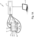
- FIGS. 1A-1D are schematic diagrams of system 10 including piezoelectric transducers 12A-12D that can be used to remove unfused powder from internal passages 14A-14F of additive-manufactured part 16.
- FIGS. 1A-1D illustrate system 10 having additive-manufactured part 16 disposed at varying orientations. That is, FIG. 1A illustrates additive-manufactured part 16 at a first orientation, and FIGS. 1B-1D illustrate additive-manufactured part 16 rotated by successive 90 degree increments. Though the examples of FIGS. 1A-1D illustrate additive-manufactured part 16 rotated by successive 90 degree increments, it should be understood that additive-manufactured part 16 can be rotated by other increments within any of combination of six degrees of rotational freedom.
- Additive-manufactured part 16 can be any additive-manufactured part having internal passages, cavities, or other components that may contain residual (i.e., unfused) powder, such as metal powder or other material used for the additive-manufacture of part 16.
- additive-manufactured part 16 is a component used by an aircraft, such as a heat exchanger (e.g., a plate-fin heat exchanger), an airfoil (e.g., rotor blade, fan blade, or other airfoil) used in a gas turbine engine of the aircraft, or other component having internal passages that may contain residual powder after the additive-manufacture of the part.
- a heat exchanger e.g., a plate-fin heat exchanger
- an airfoil e.g., rotor blade, fan blade, or other airfoil
- Internal passages 14A-14F are internal passageways (e.g., extending within an interior) of additive-manufactured part 16 that terminate in at least one open end at an exterior of additive-manufactured part 16.
- Internal passages 14A-14F can be, in some examples, narrow passages (e.g., less than one millimeter in width) having thin walls (e.g., less than one millimeter in width).
- internal passages 14A-14F can be linear (e.g., passages 14D, 14E, and 14F), curvilinear (e.g., passages 14A, 14B, and 14C), and may intersect at one or more locations.
- FIG. 1A internal passages 14A-14F can be linear (e.g., passages 14D, 14E, and 14F), curvilinear (e.g., passages 14A, 14B, and 14C), and may intersect at one or more locations.
- any one or more of internal passages 14A-14F can terminate at a closed end (e.g., a dead end) within the interior of additive-manufactured part 16 (e.g., passages 14A and 14C).
- a closed end e.g., a dead end
- FIGS. 1A-1D illustrate a schematic cutaway view of additive-manufactured part 16 to more clearly show internal passages 14A-14F, it should be understood that additive-manufactured part 16 is a three-dimensional part, and internal passages 14A-14F are also three-dimensional in nature.
- Piezoelectric transducers 12A-12D are electroacoustic transducers, such as quartz piezoelectric crystal transducers, piezoelectric ceramic transducers, piezo-polymer transducers, piezoelectric ultrasonic transducers, or other types of piezoelectric transducers.
- Function generator 18 is an electronic device capable of generating various types of waveforms (e.g., sine wave, square wave, triangular wave, sawtooth wave, or other types of waveforms) at various frequencies and amplitudes (e.g., according to a selectable power level).
- Computer 20 is a general purpose computer or other computerized controller having one or more processors, one or more input/output devices (e.g., communication devices, user interface devices, or other input/output devices), and computer-readable memory encoded with instructions that, when executed by the one or more processors, cause computer 20 to execute in accordance with techniques described herein.
- input/output devices e.g., communication devices, user interface devices, or other input/output devices
- computer-readable memory encoded with instructions that, when executed by the one or more processors, cause computer 20 to execute in accordance with techniques described herein.
- piezoelectric transducers 12A-12D are attached to locations on the exterior of additive-manufactured part 16. While the examples of FIGS. 1A-1D illustrate and describe the use of four individual piezoelectric transducers, it should be understood that techniques described herein are applicable to the use of any number of one or more piezoelectric transducers.
- Function generator 18 is electrically connected to each of piezoelectric transducers 12A-12D to supply electrical waveforms (e.g., sine, square, triangle, sawtooth, or other waveforms) to piezoelectric transducers 12A-12D at varying amplitudes and frequencies.
- Computer 20, in the examples of FIGS. 1A-1D is electrically and/or communicatively coupled to function generator 18. In some examples, computer 20 can control operation of function generator 18 to cause function generator 18 to supply the electrical waveforms at the varying amplitudes and frequencies. In other examples, computer 20 may not be coupled with function generator 18.
- function generator 18 can be manually adjusted by an operator via a user interface of function generator 18 (e.g., knobs, buttons, touch-screen user interface, or other user interface elements) to supply the electrical waveforms at the varying amplitudes and frequencies.
- a user interface of function generator 18 e.g., knobs, buttons, touch-screen user interface, or other user interface elements
- piezoelectric transducers 12A-12D are attached at various locations of the exterior of additive-manufactured part 16 and are driven to induce vibrations at varying amplitudes and frequencies by electrical waveforms supplied by function generator 18. Vibration of piezoelectric transducers 12A-12D induces vibration of additive-manufactured part 16, including internal components such as walls of internal passages 14A-14F. The induced vibrations can dislodge unfused powder contained within internal passages 14A-14F that can be vibrated to exit open ends of internal passages 14A-14F at the exterior of additive-manufactured part 16.
- Function generator 18 drives piezoelectric transducers 12A-12D at varying frequencies and amplitudes (e.g., according to a selected electrical power level of function generator 18). For instance, function generator 18 can drive piezoelectric transducers 12A-12D through a range of frequencies at a first power level (i.e., defining a first amplitude), adjust the electrical input to a second power level (i.e., defining a second amplitude), and drive piezoelectric transducers 12A-12D through the range of frequencies at the second power level. Function generator 18 can repeat the process of setting electrical power levels and scanning frequencies to drive piezoelectric transducers 12A-12D through a range of electrical power levels (corresponding to a range of amplitudes) and frequencies.
- the ranges of power levels and frequencies utilized by function generator 18 can vary according to the size, material, and type of additive-manufactured part 16. For instance, the range of power levels can vary from electrical power levels on the order of Watts (W) to milliwatts (mW), and the range of frequencies can vary from frequencies on the order of Hertz (Hz) to megahertz (MHz).
- W Watts
- mW milliwatts
- Hz Hertz
- MHz megahertz
- Vibration of additive-manufactured part 16 induced by piezoelectric transducers 12A-12D can excite resonant frequencies of walls of internal passages 14A-14F to cause unfused powder to travel through internal passages 14A-14F and exit additive-manufactured part 16.
- Locations of piezoelectric transducers 12A-12D and/or orientation changes of additive-manufactured part 16 can be based on known orientations and/or paths of internal passages 14A-14F.
- computer 20 can store a 3D computer model of additive-manufactured part 16 from which orientations and/or paths of internal passages 14A-14F can be identified.
- Locations of piezoelectric transducers 12A-12D can be selected and/or changed based on the known orientations and/or paths of internal passages 14A-14F to facilitate movement of residual powder and exit of the powder from additive-manufactured part 16.
- internal passage 14A has a first, open end that terminates at the exterior of additive-manufactured part 16, a second, closed end that terminates within the interior of additive-manufactured part 16, and an orientation change of the path of internal passage 14A between the open end and the closed end.
- any one or more of piezoelectric transducers 12A-12D can be first attached at a location of the exterior of additive-manufactured part 16 that causes vibration of the walls of internal passage 14A near to the open end (e.g., locations near to and/or on opposite sides of the open end), thereby causing unfused powder to exit additive-manufactured part 16 from the open end when driven to vibrate by function generator 18.
- the locations of one or more of piezoelectric transducers 12A-12D can be subsequently changed to cause vibration of the walls of internal passage 14A near to the closed end, thereby dislodging and causing movement of residual powder contained within internal passage 14A in a direction from the closed end to the open end to facilitate exit of the residual powder from additive-manufactured part 16.
- Such location changes of piezoelectric transducers 12A-12D can be performed in combination with orientation changes of additive-manufactured part 16 to help facilitate the movement of unfused powder through internal passages 14A-14F to exit additive-manufactured part 16.
- the orientation of additive-manufactured part 16 can be changed based on the known orientations and paths of internal passages 14A-14F to align open ends of internal passages 14A-14F with gravity (i.e., such that the open ends face the ground) to facilitate movement of the unfused powder through portions of internal passages 14A-14F and the eventual exit of the powder through the open ends.
- Orientation changes of additive-manufactured part 16 can be performed manually (e.g., hand held) or accomplished via a manually and/or programmatically controlled fixture that secures additive-manufactured part 16.
- additive-manufactured part 16 can be secured within a fixture (not shown) that has, e.g., six degrees of rotational freedom to enable accurate and repeatable orientation changes of additive-manufactured part 16.
- a fixture can be manually operated (e.g., by a user) and/or controlled programmatically for orientation changes, such as by computer 20 or other computerized controller.
- the amount of unfused powder that exits additive-manufactured part 16 is monitored. For instance, the amount of unfused powder that exits additive-manufactured part 16 can be collected and monitored for weight, volume, or other indication of the amount of the unfused powder that has exited additive-manufactured part 16 during the vibration operations.
- the amount of unfused powder that has exited can be compared to an estimated amount of unfused powder contained within internal passages 14A-14F.
- the estimated amount of unfused powder contained within internal passages 14A-14F can be determined based on the 3D computer model of additive-manufactured part 16, such as an amount corresponding to (e.g., equal to or within a defined percentage of) the volume of internal passages 14A-14F.
- a threshold deviation from the estimated amount of unfused powder contained within internal passages 14A-14F e.g., a threshold weight deviation, a threshold volume deviation, a percentage of weight and/or volume deviation, or other deviations
- a defined schedule of frequency changes of the input signal provided to piezoelectric transducers 12A-12D, amplitude changes of the input signal provided to piezoelectric transducers 12A-12D, orientation changes of additive-manufactured part 16, and location changes of piezoelectric transducers 12A-12D can be created.
- Subsequent additive-manufactured versions of additive-manufactured part 16 can be subjected to the defined schedule to effectively remove the unfused powder from internal passages of the subsequent part.
- system 10 implementing techniques of this disclosure can be utilized to remove unfused powder from internal passages 14A-14F from additive-manufactured part 16, including those internal passages that may be narrow, include changes of orientation and/or direction, terminate at a closed end within additive-manufactured part 16, or are otherwise prone to trapping unfused powder.
- the techniques can therefore help to increase the feasibility of manufacturing parts via additive manufacturing techniques by removing unfused powder that may otherwise render the use of additive manufacturing techniques unfeasible for production of the part.
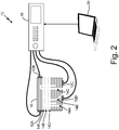
- FIG. 2 is a schematic diagram of system 10 of FIGS. 1A-1D showing piezoelectric transducers 12A-12D attached at different locations to the exterior of additive-manufactured part 16. As illustrated in FIG. 2 , each of piezoelectric transducers 12A-12D is attached at a different location (as compared with the locations illustrated in FIGS. 1A-1D ). As described above, such location changes of piezoelectric transducers 12A-12D can be based on known orientations and/or path directions of internal passages 14A-14F to facilitate movement of unfused powder through internal passages 14A-14F to exit additive-manufactured part 16.
- any one or more of piezoelectric transducers 12A-12D can be repeated multiple times to facilitate the vibration of internal components of additive-manufactured part 16 and movement of unfused powder through internal passages 14A-14F to exit additive-manufactured part 16.
- FIG. 3 is a flow diagram illustrating example operations to remove unfused powder from an additive-manufactured part. For purposes of clarity and ease of discussion, the example operations are described below within the context of system 10 of FIGS. 1A-1D and FIG. 2 .
- Piezoelectric transducers are attached to a plurality of locations on an exterior of an additive-manufactured part (Step 22).
- piezoelectric transducers 12A-12D can be attached to the exterior of additive-manufactured part 16.
- the additive-manufactured part is vibrated by driving the piezoelectric transducers at varying amplitudes and frequencies (Step 24).
- function generator 18 can drive piezoelectric transducers 12A-12D at varying amplitudes and frequencies.
- An amount of unfused powder that exits the additive-manufactured part is monitored (Step 26).
- the amount of unfused (i.e., residual) powder that exits additive-manufactured part 16 can be monitored, such as by collecting the unfused powder and monitoring a weight, volume, or other indication of the amount of unfused powder that has exited additive-manufactured part 16.
- Step 28 It is determined whether the amount of unfused powder that exits the additive-manufactured part is within a threshold deviation from an estimated amount of unfused powder contained within the internal passages of the additive-manufactured part (Step 28).
- computer 20 can store a 3D computer model of the structure of additive-manufactured part 16.
- the estimated amount of unfused powder can be determined based on the volume of internal passages 14A-14F, such as volume equal to or within a threshold percentage of (e.g., 80 percent, 90 percent, or other threshold percentage) of the volume of internal passages 14A-14F.
- the amount of unfused powder that exits additive-manufactured part 16 can be compared to the estimated amount to determine a deviation (i.e., difference) between the amount of unfused powder that exits additive-manufactured part 16 and the estimated amount.
- the deviation can be compared to a threshold deviation, such as a threshold volume deviation, a threshold weight deviation, a threshold percentage deviation of volume and/or weight, or other threshold deviations.
- a defined schedule of frequency changes, amplitude changes, orientation changes, and transducer locations is created (Step 32).
- the defined schedule corresponds to the frequencies, amplitudes, orientations, and transducer locations utilized during the vibration operations (i.e., Steps 22, 24, and 26) to cause the exit of the amount of unfused powder from additive-manufactured part 16 that is within the threshold deviation.
- Subsequent additive-manufactured versions of the part can then be subjected to the defined schedule to effectively remove the unfused powder from the additive-manufactured part.
- Step 30 In response to determining that the amount of unfused powder that exits the additive-manufactured part is not within the threshold deviation from the estimated amount of unfused powder ("NO" branch of Step 28), one or more of the orientation of the part and locations of the piezoelectric transducers are altered (Step 30) and the additive-manufactured part is vibrated by driving the piezoelectric transducers at varying amplitudes and frequencies (Step 24).
- the orientation of additive-manufactured part 16 and/or locations of piezoelectric transducers 12A-12D can be altered individually or in combination to facilitate movement of unfused powder through internal passages 14A-14F to exit additive-manufactured part 16 during vibration of additive-manufactured part 16 via piezoelectric transducers 12A-12D.
- the execution of Steps 24, 26, 28, and 30 are iterative in nature, and can be performed until the "YES" branch of Step 28 is satisfied or, in certain examples, a threshold number of times (e.g., 5, 10, 50, or more iterations).
- techniques of this disclosure can be utilized to remove unfused powder from internal passages of an additive-manufactured part, including those passages that may be prone to trapping unfused powder.
- the techniques described herein can therefore help to remove residual powder that may otherwise be impractical to remove, thereby increasing the likelihood that parts can feasibly be produced via additive manufacturing techniques.
- a method of removing unfused powder from internal passages of an additive-manufactured part includes attaching piezoelectric transducers to a plurality of locations on an exterior of the part. The method further includes vibrating the part by driving the piezoelectric transducers at varying amplitudes and frequencies, and monitoring an amount of the unfused powder that exits the part.
- the method of the preceding paragraph can optionally include, additionally and/or alternatively, any one or more of the following features, configurations, operations, and/or additional components:
- the method can further include altering an orientation of the part and repeating the vibrating step by driving the piezoelectric transducers at the varying amplitudes and frequencies.
- Altering the orientation of the part can include altering the orientation of the part based on known orientations of the internal passages within the part.
- Altering the orientation of the part based on the known orientations of the internal passages within the part can include identifying the known orientations of the internal passages using a computer model of the part.
- Altering the orientation of the part based on the known orientations of the internal passages within the part can include identifying that one or more of the internal passages changes direction within the part.
- the method can further include identifying that one or more of the internal passages terminates at a closed end within the part.
- Altering the orientation of the part can include altering the orientation of the part based on an orientation of the one or more of the internal passages that terminates at the closed end within the part.
- Altering the orientation of the part can include altering the orientation of the part based on the amount of the unfused powder that exits the part.
- Vibrating the part by driving the piezoelectric transducers at the varying amplitudes and frequencies can include driving the piezoelectric transducers at the varying amplitudes and frequencies using an electronic function generator coupled to the piezoelectric transducers.
- the method can further include changing locations of one or more of the piezoelectric transducers and repeating the vibrating step by driving the piezoelectric transducers at the varying amplitudes and frequencies.
- Changing the locations of the one or more of the piezoelectric transducers can include changing the locations of the one or more of the piezoelectric transducers based on known orientations of the internal passages within the part.
- the method can further include creating a defined schedule of frequency changes, amplitude changes, and piezoelectric transducer locations based upon the monitoring of the amount of the unfused powder that exits the part.
- the method can further include identifying an estimated amount of unfused powder contained within the internal passages of the part.
- Creating the defined schedule can include creating the defined schedule in response to determining that the amount of the unfused powder that exits the part is within a threshold deviation from the estimated amount of unfused powder contained within the internal passages of the part.
- Identifying the estimated amount of unfused powder contained within the internal passages of the part can include: determining, using a computer model of the part, a volume of the internal passages within the part; and identifying the estimated amount of unfused powder contained within the internal passages of the part based on the determined volume of the internal passages within the part.
- a method includes attaching a plurality of piezoelectric transducers to a plurality of locations of an exterior of an additive-manufactured part having internal passages terminating at one or more open ends at the exterior of the part.
- the method further includes vibrating the part by driving the plurality of piezoelectric transducers at varying amplitudes and frequencies, and monitoring an amount of unfused powder that exits the one or more open ends at the exterior of the part.
- the method further includes, in response to determining that the amount of unfused powder that exits the one or more open ends exceeds a threshold deviation from an estimated amount of unfused powder contained within the internal passages of the part: changing at least one of an orientation of the part and locations of one or more of the plurality of piezoelectric transducers; and repeating the vibrating and monitoring steps by driving the plurality of piezoelectric transducers at the varying amplitudes and frequencies and monitoring the amount of unfused powder that exits the one or more open ends at the exterior of the part.
- the method further includes, in response to determining that the amount of unfused powder that exits the one or more open ends does not exceed the threshold deviation from the estimated amount of unfused powder contained within the internal passages of the part, creating a defined schedule of frequency changes, amplitude changes, orientation changes, and transducer locations associated with the part.
- the method of the preceding paragraph can optionally include, additionally and/or alternatively, any one or more of the following features, configurations, operations, and/or additional components:
- Changing the at least one of the orientation of the part and the locations of one or more of the plurality of piezoelectric transducers can include changing the at least one of the orientation of the part and the locations of one or more of the plurality of piezoelectric transducers based on known orientations of the internal passages within the part.
- the method can further include determining the estimated amount of unfused powder contained within the internal passages of the part based on a known volume of the internal passages of the part.
- the method can further include identifying the known volume of the internal passages of the part using a computer model of the part.
- Changing the at least one of the orientation of the part and the locations of one or more of the plurality of piezoelectric transducers can include changing, in combination, both the orientation of the part and the locations of one or more of the plurality of piezoelectric transducers.
- a system includes an additive-manufacture part comprising a plurality of internal passages, a plurality of piezoelectric transducers, an electronic function generator, and a computer.
- the plurality of piezoelectric transducers are attached to a plurality of locations on an exterior of the additive-manufactured part.
- the electronic function generator is electrically coupled to each of the plurality of piezoelectric transducers.
- the computer is communicatively coupled with the electronic function generator and is encoded with computer-readable instructions that cause the computer to control the electronic function generator to drive the plurality of piezoelectric transducers at varying amplitudes and frequencies to vibrate the additive-manufactured part.
- the computer can store a three-dimensional model of the additive-manufactured part defining orientations of the plurality of internal passages.
- the computer-readable instructions can cause the computer to control the electronic function generator to drive the plurality of piezoelectric transducers at the varying amplitudes and frequencies based on the orientations of the plurality of internal passages defined by the three-dimensional model of the additive-manufactured part.
Landscapes
- Engineering & Computer Science (AREA)
- Manufacturing & Machinery (AREA)
- Chemical & Material Sciences (AREA)
- Materials Engineering (AREA)
- Mechanical Engineering (AREA)
- Physics & Mathematics (AREA)
- Optics & Photonics (AREA)
- Life Sciences & Earth Sciences (AREA)
- Sustainable Development (AREA)
Abstract
Description
- The present disclosure relates generally to post processing of additive-manufactured parts, and more particularly to the use of piezoelectric transducers to remove unfused powder from an additive-manufactured part.
- Additive manufacturing techniques can be used to build parts in a layer-by-layer fashion to arrive at a monolithic structure, thereby reducing or eliminating the need for complex casting, machining, and fabrication operations. Such additive manufacturing techniques typically involve the deposition of a thin layer of powder material (e.g., metal powder) on a work stage. A portion of the layer is solidified using, e.g., selective laser sintering, direct metal laser sintering, or selective laser melting according to a three-dimensional (3D) computer model of the part. The solidified portions of the layer form a cross-section of the part at a corresponding elevation defined by the 3D computer model. The work stage is subsequently lowered and a new layer of powder material is introduced, portions of which are solidified to produce the cross-section of the part at the new elevation according to the 3D model. The work stage lowering and selective solidification are repeated until the final structure of the finished part is achieved.
- Additive manufacturing techniques can be used to form complex parts having numerous internal walls, passages, cavities, or other components. Such internal components typically require the post-processing removal of residual (i.e., unfused) powder prior to disposition and ultimate use of the part. It can be difficult, however, to remove residual powder from the interior of complex parts having numerous internal passages that may be narrow, winding, terminating at a dead end within the part, or otherwise prone to trapping residual powder. In some cases, the inability to remove residual powder from a finished part can render the use of additive manufacturing techniques unfeasible for production of the part.
- In one example, a method of removing unfused powder from internal passages of an additive-manufactured part includes attaching piezoelectric transducers to a plurality of locations on an exterior of the part. The method further includes vibrating the part by driving the piezoelectric transducers at varying amplitudes and frequencies, and monitoring an amount of the unfused powder that exits the part.
- In another example, a method includes attaching a plurality of piezoelectric transducers to a plurality of locations of an exterior of an additive-manufactured part having internal passages terminating at one or more open ends at the exterior of the part. The method further includes vibrating the part by driving the plurality of piezoelectric transducers at varying amplitudes and frequencies, and monitoring an amount of unfused powder that exits the one or more open ends at the exterior of the part. The method further includes, in response to determining that the amount of unfused powder that exits the one or more open ends exceeds a threshold deviation from an estimated amount of unfused powder contained within the internal passages of the part: changing at least one of an orientation of the part and locations of one or more of the plurality of piezoelectric transducers; and repeating the vibrating and monitoring steps by driving the plurality of piezoelectric transducers at the varying amplitudes and frequencies and monitoring the amount of unfused powder that exits the one or more open ends at the exterior of the part. The method further includes, in response to determining that the amount of unfused powder that exits the one or more open ends does not exceed the threshold deviation from the estimated amount of unfused powder contained within the internal passages of the part, creating a defined schedule of frequency changes, amplitude changes, orientation changes, and transducer locations associated with the part.
- In another example, a system includes an additive-manufacture part comprising a plurality of internal passages, a plurality of piezoelectric transducers, an electronic function generator, and a computer. The plurality of piezoelectric transducers are attached to a plurality of locations on an exterior of the additive-manufactured part. The electronic function generator is electrically coupled to each of the plurality of piezoelectric transducers. The computer is communicatively coupled with the electronic function generator and is encoded with computer-readable instructions that cause the computer to control the electronic function generator to drive the plurality of piezoelectric transducers at varying amplitudes and frequencies to vibrate the additive-manufactured part.
-
-
FIGS. 1A-1D are schematic diagrams of an example system including piezoelectric transducers that can be used to remove unfused powder from internal passages of an additive-manufactured part illustrated at varying orientations. -
FIG. 2 is a schematic diagram of the example system ofFIGS. 1A-1D showing the piezoelectric transducers at different locations. -
FIG. 3 is a flow diagram illustrating example operations to remove unfused powder from an additive-manufactured part. - As described herein, piezoelectric transducers can be utilized for the removal of residual (i.e., unfused) powder from internal passages of an additive-manufactured part. The piezoelectric transducers are attached to an exterior of the part and driven at varying amplitudes and frequencies to induce vibration of the part to dislodge residual powder from the internal passages. An orientation of the part and/or locations of the transducers can be altered to facilitate movement of the residual powder within the interior passages to an opening that terminates at the exterior of the part. The sequence of orientation and/or transducer location changes can be determined based on orientations of the internal passages defined by a three-dimensional (3D) computer model of the part, such as a computer-aided design (CAD) file, an Additive Manufacturing File (AMF), or other computer model defining the 3D structure of the part.
- An amount of unfused powder that exits the part during the vibration operations is monitored, and can be compared to an estimated amount of residual powder contained within the internal passages, such as an amount of residual powder corresponding to a volume of the internal passages (e.g., estimated based on the 3D computer model). A defined schedule of frequency changes, amplitude changes, orientation changes, and transducer locations is created based on the operations that produced an amount of unfused powder exiting the part that is within a threshold deviation (e.g., a threshold volume, weight, percentage of material, or other threshold deviations) from the estimated amount of residual powder contained within the internal passages. Subsequent additive-manufactured versions of the part can then be subjected to the defined schedule to effectively remove the unfused powder from the additive-manufactured part.
- Accordingly, techniques of this disclosure can be utilized to remove residual (i.e., unfused) powder from internal passages of an additive-manufactured part. The techniques can effectively remove unfused powder from passages that may be narrow, winding, terminating at a closed end (i.e., a dead end) within the part, or otherwise prone to trapping residual powder. As such, techniques described herein can help to remove residual powder from the additive-manufactured part that may otherwise render the use of additive manufacturing techniques unfeasible for production of the part.
-
FIGS. 1A-1D are schematic diagrams ofsystem 10 includingpiezoelectric transducers 12A-12D that can be used to remove unfused powder frominternal passages 14A-14F of additive-manufacturedpart 16.FIGS. 1A- 1D illustrate system 10 having additive-manufacturedpart 16 disposed at varying orientations. That is,FIG. 1A illustrates additive-manufacturedpart 16 at a first orientation, andFIGS. 1B-1D illustrate additive-manufacturedpart 16 rotated by successive 90 degree increments. Though the examples ofFIGS. 1A-1D illustrate additive-manufacturedpart 16 rotated by successive 90 degree increments, it should be understood that additive-manufacturedpart 16 can be rotated by other increments within any of combination of six degrees of rotational freedom. - As illustrated in
FIG. 1A ,system 10 further includeselectronic function generator 18 andcomputer 20. Additive-manufacturedpart 16 can be any additive-manufactured part having internal passages, cavities, or other components that may contain residual (i.e., unfused) powder, such as metal powder or other material used for the additive-manufacture ofpart 16. In some examples, additive-manufacturedpart 16 is a component used by an aircraft, such as a heat exchanger (e.g., a plate-fin heat exchanger), an airfoil (e.g., rotor blade, fan blade, or other airfoil) used in a gas turbine engine of the aircraft, or other component having internal passages that may contain residual powder after the additive-manufacture of the part. -
Internal passages 14A-14F are internal passageways (e.g., extending within an interior) of additive-manufacturedpart 16 that terminate in at least one open end at an exterior of additive-manufacturedpart 16.Internal passages 14A-14F can be, in some examples, narrow passages (e.g., less than one millimeter in width) having thin walls (e.g., less than one millimeter in width). As illustrated inFIG. 1A ,internal passages 14A-14F can be linear (e.g.,passages passages FIG. 1A , any one or more ofinternal passages 14A-14F can terminate at a closed end (e.g., a dead end) within the interior of additive-manufactured part 16 (e.g.,passages FIGS. 1A-1D illustrate a schematic cutaway view of additive-manufacturedpart 16 to more clearly showinternal passages 14A-14F, it should be understood that additive-manufacturedpart 16 is a three-dimensional part, andinternal passages 14A-14F are also three-dimensional in nature. -
Piezoelectric transducers 12A-12D are electroacoustic transducers, such as quartz piezoelectric crystal transducers, piezoelectric ceramic transducers, piezo-polymer transducers, piezoelectric ultrasonic transducers, or other types of piezoelectric transducers.Function generator 18 is an electronic device capable of generating various types of waveforms (e.g., sine wave, square wave, triangular wave, sawtooth wave, or other types of waveforms) at various frequencies and amplitudes (e.g., according to a selectable power level).Computer 20 is a general purpose computer or other computerized controller having one or more processors, one or more input/output devices (e.g., communication devices, user interface devices, or other input/output devices), and computer-readable memory encoded with instructions that, when executed by the one or more processors, causecomputer 20 to execute in accordance with techniques described herein. - As illustrated in
FIG. 1A ,piezoelectric transducers 12A-12D are attached to locations on the exterior of additive-manufacturedpart 16. While the examples ofFIGS. 1A-1D illustrate and describe the use of four individual piezoelectric transducers, it should be understood that techniques described herein are applicable to the use of any number of one or more piezoelectric transducers. -
Function generator 18 is electrically connected to each ofpiezoelectric transducers 12A-12D to supply electrical waveforms (e.g., sine, square, triangle, sawtooth, or other waveforms) topiezoelectric transducers 12A-12D at varying amplitudes and frequencies.Computer 20, in the examples ofFIGS. 1A-1D , is electrically and/or communicatively coupled tofunction generator 18. In some examples,computer 20 can control operation offunction generator 18 to causefunction generator 18 to supply the electrical waveforms at the varying amplitudes and frequencies. In other examples,computer 20 may not be coupled withfunction generator 18. Rather, in such examples,function generator 18 can be manually adjusted by an operator via a user interface of function generator 18 (e.g., knobs, buttons, touch-screen user interface, or other user interface elements) to supply the electrical waveforms at the varying amplitudes and frequencies. - In operation,
piezoelectric transducers 12A-12D are attached at various locations of the exterior of additive-manufacturedpart 16 and are driven to induce vibrations at varying amplitudes and frequencies by electrical waveforms supplied byfunction generator 18. Vibration ofpiezoelectric transducers 12A-12D induces vibration of additive-manufacturedpart 16, including internal components such as walls ofinternal passages 14A-14F. The induced vibrations can dislodge unfused powder contained withininternal passages 14A-14F that can be vibrated to exit open ends ofinternal passages 14A-14F at the exterior of additive-manufacturedpart 16. -
Function generator 18 drivespiezoelectric transducers 12A-12D at varying frequencies and amplitudes (e.g., according to a selected electrical power level of function generator 18). For instance,function generator 18 can drivepiezoelectric transducers 12A-12D through a range of frequencies at a first power level (i.e., defining a first amplitude), adjust the electrical input to a second power level (i.e., defining a second amplitude), and drivepiezoelectric transducers 12A-12D through the range of frequencies at the second power level.Function generator 18 can repeat the process of setting electrical power levels and scanning frequencies to drivepiezoelectric transducers 12A-12D through a range of electrical power levels (corresponding to a range of amplitudes) and frequencies. The ranges of power levels and frequencies utilized byfunction generator 18 can vary according to the size, material, and type of additive-manufacturedpart 16. For instance, the range of power levels can vary from electrical power levels on the order of Watts (W) to milliwatts (mW), and the range of frequencies can vary from frequencies on the order of Hertz (Hz) to megahertz (MHz). - Vibration of additive-manufactured
part 16 induced bypiezoelectric transducers 12A-12D can excite resonant frequencies of walls ofinternal passages 14A-14F to cause unfused powder to travel throughinternal passages 14A-14F and exit additive-manufacturedpart 16. Locations ofpiezoelectric transducers 12A-12D and/or orientation changes of additive-manufacturedpart 16 can be based on known orientations and/or paths ofinternal passages 14A-14F. For instance,computer 20 can store a 3D computer model of additive-manufacturedpart 16 from which orientations and/or paths ofinternal passages 14A-14F can be identified. Locations ofpiezoelectric transducers 12A-12D can be selected and/or changed based on the known orientations and/or paths ofinternal passages 14A-14F to facilitate movement of residual powder and exit of the powder from additive-manufacturedpart 16. - As an example, it can be determined (e.g., manually and/or programmatically) that
internal passage 14A has a first, open end that terminates at the exterior of additive-manufacturedpart 16, a second, closed end that terminates within the interior of additive-manufacturedpart 16, and an orientation change of the path ofinternal passage 14A between the open end and the closed end. In response, any one or more ofpiezoelectric transducers 12A-12D can be first attached at a location of the exterior of additive-manufacturedpart 16 that causes vibration of the walls ofinternal passage 14A near to the open end (e.g., locations near to and/or on opposite sides of the open end), thereby causing unfused powder to exit additive-manufacturedpart 16 from the open end when driven to vibrate byfunction generator 18. The locations of one or more ofpiezoelectric transducers 12A-12D can be subsequently changed to cause vibration of the walls ofinternal passage 14A near to the closed end, thereby dislodging and causing movement of residual powder contained withininternal passage 14A in a direction from the closed end to the open end to facilitate exit of the residual powder from additive-manufacturedpart 16. - Such location changes of
piezoelectric transducers 12A-12D (an example of which is illustrated and described below with respect toFIG. 2 ), can be performed in combination with orientation changes of additive-manufacturedpart 16 to help facilitate the movement of unfused powder throughinternal passages 14A-14F to exit additive-manufacturedpart 16. For instance, the orientation of additive-manufacturedpart 16 can be changed based on the known orientations and paths ofinternal passages 14A-14F to align open ends ofinternal passages 14A-14F with gravity (i.e., such that the open ends face the ground) to facilitate movement of the unfused powder through portions ofinternal passages 14A-14F and the eventual exit of the powder through the open ends. - Orientation changes of additive-manufactured
part 16 can be performed manually (e.g., hand held) or accomplished via a manually and/or programmatically controlled fixture that secures additive-manufacturedpart 16. For example, additive-manufacturedpart 16 can be secured within a fixture (not shown) that has, e.g., six degrees of rotational freedom to enable accurate and repeatable orientation changes of additive-manufacturedpart 16. Such a fixture can be manually operated (e.g., by a user) and/or controlled programmatically for orientation changes, such as bycomputer 20 or other computerized controller. - The amount of unfused powder that exits additive-manufactured
part 16 is monitored. For instance, the amount of unfused powder that exits additive-manufacturedpart 16 can be collected and monitored for weight, volume, or other indication of the amount of the unfused powder that has exited additive-manufacturedpart 16 during the vibration operations. The amount of unfused powder that has exited can be compared to an estimated amount of unfused powder contained withininternal passages 14A-14F. The estimated amount of unfused powder contained withininternal passages 14A-14F can be determined based on the 3D computer model of additive-manufacturedpart 16, such as an amount corresponding to (e.g., equal to or within a defined percentage of) the volume ofinternal passages 14A-14F. - In response to determining that the amount of unfused powder that exits additive-manufactured
part 16 is within a threshold deviation from the estimated amount of unfused powder contained withininternal passages 14A-14F (e.g., a threshold weight deviation, a threshold volume deviation, a percentage of weight and/or volume deviation, or other deviations), a defined schedule of frequency changes of the input signal provided topiezoelectric transducers 12A-12D, amplitude changes of the input signal provided topiezoelectric transducers 12A-12D, orientation changes of additive-manufacturedpart 16, and location changes ofpiezoelectric transducers 12A-12D can be created. Subsequent additive-manufactured versions of additive-manufacturedpart 16 can be subjected to the defined schedule to effectively remove the unfused powder from internal passages of the subsequent part. - Accordingly,
system 10 implementing techniques of this disclosure can be utilized to remove unfused powder frominternal passages 14A-14F from additive-manufacturedpart 16, including those internal passages that may be narrow, include changes of orientation and/or direction, terminate at a closed end within additive-manufacturedpart 16, or are otherwise prone to trapping unfused powder. The techniques can therefore help to increase the feasibility of manufacturing parts via additive manufacturing techniques by removing unfused powder that may otherwise render the use of additive manufacturing techniques unfeasible for production of the part. -
FIG. 2 is a schematic diagram ofsystem 10 ofFIGS. 1A-1D showingpiezoelectric transducers 12A-12D attached at different locations to the exterior of additive-manufacturedpart 16. As illustrated inFIG. 2 , each ofpiezoelectric transducers 12A-12D is attached at a different location (as compared with the locations illustrated inFIGS. 1A-1D ). As described above, such location changes ofpiezoelectric transducers 12A-12D can be based on known orientations and/or path directions ofinternal passages 14A-14F to facilitate movement of unfused powder throughinternal passages 14A-14F to exit additive-manufacturedpart 16. The movement of any one or more ofpiezoelectric transducers 12A-12D can be repeated multiple times to facilitate the vibration of internal components of additive-manufacturedpart 16 and movement of unfused powder throughinternal passages 14A-14F to exit additive-manufacturedpart 16. -
FIG. 3 is a flow diagram illustrating example operations to remove unfused powder from an additive-manufactured part. For purposes of clarity and ease of discussion, the example operations are described below within the context ofsystem 10 ofFIGS. 1A-1D andFIG. 2 . - Piezoelectric transducers are attached to a plurality of locations on an exterior of an additive-manufactured part (Step 22). For example,
piezoelectric transducers 12A-12D can be attached to the exterior of additive-manufacturedpart 16. The additive-manufactured part is vibrated by driving the piezoelectric transducers at varying amplitudes and frequencies (Step 24). For instance,function generator 18 can drivepiezoelectric transducers 12A-12D at varying amplitudes and frequencies. - An amount of unfused powder that exits the additive-manufactured part is monitored (Step 26). For example, the amount of unfused (i.e., residual) powder that exits additive-manufactured
part 16 can be monitored, such as by collecting the unfused powder and monitoring a weight, volume, or other indication of the amount of unfused powder that has exited additive-manufacturedpart 16. - It is determined whether the amount of unfused powder that exits the additive-manufactured part is within a threshold deviation from an estimated amount of unfused powder contained within the internal passages of the additive-manufactured part (Step 28). For instance,
computer 20 can store a 3D computer model of the structure of additive-manufacturedpart 16. The estimated amount of unfused powder can be determined based on the volume ofinternal passages 14A-14F, such as volume equal to or within a threshold percentage of (e.g., 80 percent, 90 percent, or other threshold percentage) of the volume ofinternal passages 14A-14F. The amount of unfused powder that exits additive-manufacturedpart 16 can be compared to the estimated amount to determine a deviation (i.e., difference) between the amount of unfused powder that exits additive-manufacturedpart 16 and the estimated amount. The deviation can be compared to a threshold deviation, such as a threshold volume deviation, a threshold weight deviation, a threshold percentage deviation of volume and/or weight, or other threshold deviations. - In response to determining that the amount of unfused powder that exits the additive-manufactured part is within the threshold deviation from the estimated amount of unfused powder contained within the internal passages of the additive-manufactured part ("YES" branch of Step 28), a defined schedule of frequency changes, amplitude changes, orientation changes, and transducer locations is created (Step 32). The defined schedule corresponds to the frequencies, amplitudes, orientations, and transducer locations utilized during the vibration operations (i.e., Steps 22, 24, and 26) to cause the exit of the amount of unfused powder from additive-manufactured
part 16 that is within the threshold deviation. Subsequent additive-manufactured versions of the part can then be subjected to the defined schedule to effectively remove the unfused powder from the additive-manufactured part. - In response to determining that the amount of unfused powder that exits the additive-manufactured part is not within the threshold deviation from the estimated amount of unfused powder ("NO" branch of Step 28), one or more of the orientation of the part and locations of the piezoelectric transducers are altered (Step 30) and the additive-manufactured part is vibrated by driving the piezoelectric transducers at varying amplitudes and frequencies (Step 24). For example, the orientation of additive-manufactured
part 16 and/or locations ofpiezoelectric transducers 12A-12D can be altered individually or in combination to facilitate movement of unfused powder throughinternal passages 14A-14F to exit additive-manufacturedpart 16 during vibration of additive-manufacturedpart 16 viapiezoelectric transducers 12A-12D. The execution ofSteps Step 28 is satisfied or, in certain examples, a threshold number of times (e.g., 5, 10, 50, or more iterations). - Accordingly, techniques of this disclosure can be utilized to remove unfused powder from internal passages of an additive-manufactured part, including those passages that may be prone to trapping unfused powder. The techniques described herein can therefore help to remove residual powder that may otherwise be impractical to remove, thereby increasing the likelihood that parts can feasibly be produced via additive manufacturing techniques.
- The following are non-exclusive descriptions of possible embodiments of the present invention.
- A method of removing unfused powder from internal passages of an additive-manufactured part includes attaching piezoelectric transducers to a plurality of locations on an exterior of the part. The method further includes vibrating the part by driving the piezoelectric transducers at varying amplitudes and frequencies, and monitoring an amount of the unfused powder that exits the part.
- The method of the preceding paragraph can optionally include, additionally and/or alternatively, any one or more of the following features, configurations, operations, and/or additional components:
- The method can further include altering an orientation of the part and repeating the vibrating step by driving the piezoelectric transducers at the varying amplitudes and frequencies.
- Altering the orientation of the part can include altering the orientation of the part based on known orientations of the internal passages within the part.
- Altering the orientation of the part based on the known orientations of the internal passages within the part can include identifying the known orientations of the internal passages using a computer model of the part.
- Altering the orientation of the part based on the known orientations of the internal passages within the part can include identifying that one or more of the internal passages changes direction within the part.
- The method can further include identifying that one or more of the internal passages terminates at a closed end within the part. Altering the orientation of the part can include altering the orientation of the part based on an orientation of the one or more of the internal passages that terminates at the closed end within the part.
- Altering the orientation of the part can include altering the orientation of the part based on the amount of the unfused powder that exits the part.
- Vibrating the part by driving the piezoelectric transducers at the varying amplitudes and frequencies can include driving the piezoelectric transducers at the varying amplitudes and frequencies using an electronic function generator coupled to the piezoelectric transducers.
- The method can further include changing locations of one or more of the piezoelectric transducers and repeating the vibrating step by driving the piezoelectric transducers at the varying amplitudes and frequencies.
- Changing the locations of the one or more of the piezoelectric transducers can include changing the locations of the one or more of the piezoelectric transducers based on known orientations of the internal passages within the part.
- The method can further include creating a defined schedule of frequency changes, amplitude changes, and piezoelectric transducer locations based upon the monitoring of the amount of the unfused powder that exits the part.
- The method can further include identifying an estimated amount of unfused powder contained within the internal passages of the part. Creating the defined schedule can include creating the defined schedule in response to determining that the amount of the unfused powder that exits the part is within a threshold deviation from the estimated amount of unfused powder contained within the internal passages of the part.
- Identifying the estimated amount of unfused powder contained within the internal passages of the part can include: determining, using a computer model of the part, a volume of the internal passages within the part; and identifying the estimated amount of unfused powder contained within the internal passages of the part based on the determined volume of the internal passages within the part.
- A method includes attaching a plurality of piezoelectric transducers to a plurality of locations of an exterior of an additive-manufactured part having internal passages terminating at one or more open ends at the exterior of the part. The method further includes vibrating the part by driving the plurality of piezoelectric transducers at varying amplitudes and frequencies, and monitoring an amount of unfused powder that exits the one or more open ends at the exterior of the part. The method further includes, in response to determining that the amount of unfused powder that exits the one or more open ends exceeds a threshold deviation from an estimated amount of unfused powder contained within the internal passages of the part: changing at least one of an orientation of the part and locations of one or more of the plurality of piezoelectric transducers; and repeating the vibrating and monitoring steps by driving the plurality of piezoelectric transducers at the varying amplitudes and frequencies and monitoring the amount of unfused powder that exits the one or more open ends at the exterior of the part. The method further includes, in response to determining that the amount of unfused powder that exits the one or more open ends does not exceed the threshold deviation from the estimated amount of unfused powder contained within the internal passages of the part, creating a defined schedule of frequency changes, amplitude changes, orientation changes, and transducer locations associated with the part.
- The method of the preceding paragraph can optionally include, additionally and/or alternatively, any one or more of the following features, configurations, operations, and/or additional components:
- Changing the at least one of the orientation of the part and the locations of one or more of the plurality of piezoelectric transducers can include changing the at least one of the orientation of the part and the locations of one or more of the plurality of piezoelectric transducers based on known orientations of the internal passages within the part.
- The method can further include determining the estimated amount of unfused powder contained within the internal passages of the part based on a known volume of the internal passages of the part.
- The method can further include identifying the known volume of the internal passages of the part using a computer model of the part.
- Changing the at least one of the orientation of the part and the locations of one or more of the plurality of piezoelectric transducers can include changing, in combination, both the orientation of the part and the locations of one or more of the plurality of piezoelectric transducers.
- A system includes an additive-manufacture part comprising a plurality of internal passages, a plurality of piezoelectric transducers, an electronic function generator, and a computer. The plurality of piezoelectric transducers are attached to a plurality of locations on an exterior of the additive-manufactured part. The electronic function generator is electrically coupled to each of the plurality of piezoelectric transducers. The computer is communicatively coupled with the electronic function generator and is encoded with computer-readable instructions that cause the computer to control the electronic function generator to drive the plurality of piezoelectric transducers at varying amplitudes and frequencies to vibrate the additive-manufactured part.
- The computer can store a three-dimensional model of the additive-manufactured part defining orientations of the plurality of internal passages. The computer-readable instructions can cause the computer to control the electronic function generator to drive the plurality of piezoelectric transducers at the varying amplitudes and frequencies based on the orientations of the plurality of internal passages defined by the three-dimensional model of the additive-manufactured part.
- While the invention has been described with reference to an exemplary embodiment(s), it will be understood by those skilled in the art that various changes may be made and equivalents may be substituted for elements thereof without departing from the scope of the invention. In addition, many modifications may be made to adapt a particular situation or material to the teachings of the invention without departing from the essential scope thereof. Therefore, it is intended that the invention not be limited to the particular embodiment(s) disclosed, but that the invention will include all embodiments falling within the scope of the appended claims.
Claims (15)
- A method of removing unfused powder from internal passages (14A-14F) of an additive-manufactured part, the method comprising:attaching piezoelectric transducers (12A-12D) to a plurality of locations on an exterior of the part;vibrating the part by driving the piezoelectric transducers (12A-12D) at varying amplitudes and frequencies; andmonitoring an amount of the unfused powder that exits the part.
- The method of claim 1, further comprising:altering an orientation of the part and repeating the vibrating step by driving the piezoelectric transducers (12A-12D) at the varying amplitudes and frequencies.
- The method of claim 2,
wherein altering the orientation of the part comprises altering the orientation of the part based on known orientations of the internal passages (14A-14F) within the part. - The method of claim 3,
wherein altering the orientation of the part based on the known orientations of the internal passages (14A-14F) within the part comprises identifying the known orientations of the internal passages using a computer model of the part, or
wherein altering the orientation of the part based on the known orientations of the internal passages within the part comprises identifying that one or more of the internal passages changes direction within the part, or
wherein altering the orientation of the part comprises altering the orientation of the part based on the amount of the unfused powder that exits the part. - The method of claim 2, further comprising:identifying that one or more of the internal passages (14A-14F) terminates at a closed end within the part;wherein altering the orientation of the part comprises altering the orientation of the part based on an orientation of the one or more of the internal passages (14A-14F) that terminates at the closed end within the part.
- The method of any preceding claim,
wherein vibrating the part by driving the piezoelectric transducers at the varying amplitudes and frequencies comprises driving the piezoelectric transducers (12A-12D) at the varying amplitudes and frequencies using an electronic function generator coupled to the piezoelectric transducers (12A-12D). - The method of any preceding claim, further comprising:changing locations of one or more of the piezoelectric transducers (12A-12D) and repeating the vibrating step by driving the piezoelectric transducers (12A-12D) at the varying amplitudes and frequencies, and preferablywherein changing the locations of the one or more of the piezoelectric transducers (12A-12D) comprises changing the locations of the one or more of the piezoelectric transducers based on known orientations of the internal passages within the part.
- The method of any preceding claim, further comprising:creating a defined schedule of frequency changes, amplitude changes, and piezoelectric transducer (12A-12D) locations based upon the monitoring of the amount of the unfused powder that exits the part.
- The method of claim 8, further comprising:identifying an estimated amount of unfused powder contained within the internal passages (14A-14F) of the part;wherein creating the defined schedule comprises creating the defined schedule in response to determining that the amount of the unfused powder that exits the part is within a threshold deviation from the estimated amount of unfused powder contained within the internal passages (14A-14F) of the part, and preferablywherein identifying the estimated amount of unfused powder contained within the internal passages (14A-14F) of the part comprises:determining, using a computer model of the part, a volume of the internal passages (14A-14F) within the part; andidentifying the estimated amount of unfused powder contained within the internal passages (14A-14F) of the part based on the determined volume of the internal passages (14A-14F) within the part.
- A method comprising:attaching a plurality of piezoelectric transducers (12A-12D) to a plurality of locations of an exterior of an additive-manufactured part having internal passages (14A-14F) terminating at one or more open ends at the exterior of the part;vibrating the part by driving the plurality of piezoelectric transducers (12A-12D) at varying amplitudes and frequencies;monitoring an amount of unfused powder that exits the one or more open ends at the exterior of the part;in response to determining that the amount of unfused powder that exits the one or more open ends exceeds a threshold deviation from an estimated amount of unfused powder contained within the internal passages (14A-14F) of the part:changing at least one of an orientation of the part and locations of one or more of the plurality of piezoelectric transducers (12A-12D); andrepeating the vibrating and monitoring steps by driving the plurality of piezoelectric transducers (12A-12D) at the varying amplitudes and frequencies and monitoring the amount of unfused powder that exits the one or more open ends at the exterior of the part; andin response to determining that the amount of unfused powder that exits the one or more open ends does not exceed the threshold deviation from the estimated amount of unfused powder contained within the internal passages (14A-14F) of the part:creating a defined schedule of frequency changes, amplitude changes, orientation changes, and transducer locations associated with the part.
- The method of claim 10,
wherein changing the at least one of the orientation of the part and the locations of one or more of the plurality of piezoelectric transducers comprises changing the at least one of the orientation of the part and the locations of one or more of the plurality of piezoelectric transducers based on known orientations of the internal passages within the part. - The method of claim 10 or 11, further comprising:determining the estimated amount of unfused powder contained within the internal passages of the part based on a known volume of the internal passages of the part, and preferablyfurther comprising:identifying the known volume of the internal passages of the part using a computer model of the part.
- The method of claim 10, 11 or 12,
wherein changing the at least one of the orientation of the part and the locations of one or more of the plurality of piezoelectric transducers (12A-12D) comprises changing, in combination, both the orientation of the part and the locations of one or more of the plurality of piezoelectric transducers (12A-12D). - A system comprising:an additive-manufactured part comprising a plurality of internal passages;a plurality of piezoelectric transducers (12A-12D) attached to a plurality of locations on an exterior of the additive-manufactured part;an electronic function generator electrically coupled to each of the plurality of piezoelectric transducers (12A-12D); anda computer communicatively coupled with the electronic function generator and encoded with computer-readable instructions that cause the computer to control the electronic function generator to drive the plurality of piezoelectric transducers (12A-12D) at varying amplitudes and frequencies to vibrate the additive-manufactured part.
- The system of claim 14,
wherein the computer stores a three-dimensional model of the additive-manufactured part defining orientations of the plurality of internal passages (14A-14F); and
wherein the computer-readable instructions cause the computer to control the electronic function generator to drive the plurality of piezoelectric transducers (14A-14F) at the varying amplitudes and frequencies based on the orientations of the plurality of internal passages (14A-14F) defined by the three-dimensional model of the additive-manufactured part.
Applications Claiming Priority (1)
| Application Number | Priority Date | Filing Date | Title |
|---|---|---|---|
| US15/864,265 US10946443B2 (en) | 2018-01-08 | 2018-01-08 | Removal of unfused powder from an additive-manufactured part using piezoelectric transducers |
Publications (2)
| Publication Number | Publication Date |
|---|---|
| EP3508289A1 true EP3508289A1 (en) | 2019-07-10 |
| EP3508289B1 EP3508289B1 (en) | 2022-03-02 |
Family
ID=65010634
Family Applications (1)
| Application Number | Title | Priority Date | Filing Date |
|---|---|---|---|
| EP19150806.8A Active EP3508289B1 (en) | 2018-01-08 | 2019-01-08 | Removal of unfused powder from an additive-manufactured part using piezoelectric transducers |
Country Status (2)
| Country | Link |
|---|---|
| US (1) | US10946443B2 (en) |
| EP (1) | EP3508289B1 (en) |
Cited By (1)
| Publication number | Priority date | Publication date | Assignee | Title |
|---|---|---|---|---|
| GB2582269A (en) * | 2019-03-06 | 2020-09-23 | Hieta Tech Limited | Manufacturing apparatus and method |
Families Citing this family (7)
| Publication number | Priority date | Publication date | Assignee | Title |
|---|---|---|---|---|
| KR102860981B1 (en) | 2018-02-09 | 2025-09-18 | 데시벨 테라퓨틱스, 인크. | Hypertonic pharmaceutical composition containing an anti-platinum chemoprotectant |
| US10813947B1 (en) | 2019-05-31 | 2020-10-27 | Decibel Therapeutics, Inc. | Methods of otoprotection against platinum-based antineoplastic agents |
| US11460252B2 (en) | 2020-01-24 | 2022-10-04 | Hamilton Sundstrand Corporation | Header arrangement for additively manufactured heat exchanger |
| US11453160B2 (en) | 2020-01-24 | 2022-09-27 | Hamilton Sundstrand Corporation | Method of building a heat exchanger |
| US11441850B2 (en) | 2020-01-24 | 2022-09-13 | Hamilton Sundstrand Corporation | Integral mounting arm for heat exchanger |
| US11703283B2 (en) | 2020-01-24 | 2023-07-18 | Hamilton Sundstrand Corporation | Radial configuration for heat exchanger core |
| US12233458B2 (en) | 2021-10-05 | 2025-02-25 | General Electric Company | Powder removal assemblies and methods of removing unbound particles using powder removal assemblies |
Citations (4)
| Publication number | Priority date | Publication date | Assignee | Title |
|---|---|---|---|---|
| US20160074940A1 (en) * | 2014-09-11 | 2016-03-17 | Pratt & Whitney Canada Corp. | Method of cleaning a part |
| EP3053731A1 (en) * | 2015-02-09 | 2016-08-10 | Rolls-Royce plc | Methods of manufacturing and cleaning |
| EP3199269A1 (en) * | 2016-02-01 | 2017-08-02 | United Technologies Corporation | Additive manufactured conglomerated powder removal from internal passages with co-built ultrasonic horns |
| EP3257607A1 (en) * | 2016-06-13 | 2017-12-20 | Siemens Aktiengesellschaft | Apparatus for additive manufacturing and use of the apparatus |
Family Cites Families (4)
| Publication number | Priority date | Publication date | Assignee | Title |
|---|---|---|---|---|
| US6814823B1 (en) * | 1999-09-16 | 2004-11-09 | Solidica, Inc. | Object consolidation through sequential material deposition |
| US20040159340A1 (en) * | 2002-11-11 | 2004-08-19 | Hiatt William M. | Methods for removing and reclaiming unconsolidated material from substrates following fabrication of objects thereon by programmed material consolidation techniques |
| US10913206B2 (en) | 2015-08-03 | 2021-02-09 | Delavan, Inc | Systems and methods for post additive manufacturing processing |
| US10583606B2 (en) | 2016-02-11 | 2020-03-10 | General Electric Company | Method and supports with powder removal ports for additive manufacturing |
-
2018
- 2018-01-08 US US15/864,265 patent/US10946443B2/en active Active
-
2019
- 2019-01-08 EP EP19150806.8A patent/EP3508289B1/en active Active
Patent Citations (4)
| Publication number | Priority date | Publication date | Assignee | Title |
|---|---|---|---|---|
| US20160074940A1 (en) * | 2014-09-11 | 2016-03-17 | Pratt & Whitney Canada Corp. | Method of cleaning a part |
| EP3053731A1 (en) * | 2015-02-09 | 2016-08-10 | Rolls-Royce plc | Methods of manufacturing and cleaning |
| EP3199269A1 (en) * | 2016-02-01 | 2017-08-02 | United Technologies Corporation | Additive manufactured conglomerated powder removal from internal passages with co-built ultrasonic horns |
| EP3257607A1 (en) * | 2016-06-13 | 2017-12-20 | Siemens Aktiengesellschaft | Apparatus for additive manufacturing and use of the apparatus |
Cited By (1)
| Publication number | Priority date | Publication date | Assignee | Title |
|---|---|---|---|---|
| GB2582269A (en) * | 2019-03-06 | 2020-09-23 | Hieta Tech Limited | Manufacturing apparatus and method |
Also Published As
| Publication number | Publication date |
|---|---|
| US10946443B2 (en) | 2021-03-16 |
| US20190210107A1 (en) | 2019-07-11 |
| EP3508289B1 (en) | 2022-03-02 |
Similar Documents
| Publication | Publication Date | Title |
|---|---|---|
| EP3508289B1 (en) | Removal of unfused powder from an additive-manufactured part using piezoelectric transducers | |
| EP3053731B1 (en) | Methods of manufacturing and cleaning | |
| JP6707649B2 (en) | Method and apparatus for inspecting components to be additionally manufactured | |
| CN109475936B (en) | Equipment for additive manufacturing and uses of the equipment | |
| CN107584767B (en) | Material removal equipment for incrementally manufactured components | |
| CN114514481B (en) | Motor control device and motor control method | |
| US10315272B2 (en) | Method for the production on a three-dimensional product | |
| EP3508287B1 (en) | Systems and methods for removing build material from additively manufactured parts | |
| CN109311230B (en) | Method, component and apparatus for treating a surface for additive manufacturing | |
| JP6154435B2 (en) | Servo control device with function to display online automatic adjustment status of control system | |
| Gürleyük et al. | Robust three-impulse sequence input shaper design | |
| BRPI0800703B1 (en) | method for layer coating a substrate | |
| WO1999003630A1 (en) | Apparatus and method for manufacturing a three-dimensional object | |
| CN111684449A (en) | Method and apparatus for generating scan paths for additive manufacturing using thermal and strain modeling | |
| EP3199269A1 (en) | Additive manufactured conglomerated powder removal from internal passages with co-built ultrasonic horns | |
| JP7390643B2 (en) | Vibration suppression method and vibration suppression device | |
| Nanu et al. | Study on ultrasonic stepped horn geometry design and FEM simulation | |
| CN109186911A (en) | A kind of adaptive exciting of building and dynamic characteristics identifying system and method | |
| US20220219381A1 (en) | Building an object with a three-dimensional printer using vibrational energy | |
| US11253915B2 (en) | Vibrational densification of powder supply in additive manufacturing | |
| US20240181717A1 (en) | Method of Producing Three-Dimensional Object, Control System and Additive Manufacturing Device | |
| JP2000047723A (en) | Method and device for input shape filtering using digital convolution | |
| Al-Budairi et al. | An analytical model of a longitudinal-torsional ultrasonic transducer | |
| JP6544851B2 (en) | Patent application title: Parameter setting method for positioning device, parameter setting device, and positioning device provided with the parameter setting device | |
| CN112236252B (en) | Powder removal of floating structures |
Legal Events
| Date | Code | Title | Description |
|---|---|---|---|
| PUAI | Public reference made under article 153(3) epc to a published international application that has entered the european phase |
Free format text: ORIGINAL CODE: 0009012 |
|
| STAA | Information on the status of an ep patent application or granted ep patent |
Free format text: STATUS: THE APPLICATION HAS BEEN PUBLISHED |
|
| AK | Designated contracting states |
Kind code of ref document: A1 Designated state(s): AL AT BE BG CH CY CZ DE DK EE ES FI FR GB GR HR HU IE IS IT LI LT LU LV MC MK MT NL NO PL PT RO RS SE SI SK SM TR |
|
| AX | Request for extension of the european patent |
Extension state: BA ME |
|
| STAA | Information on the status of an ep patent application or granted ep patent |
Free format text: STATUS: REQUEST FOR EXAMINATION WAS MADE |
|
| 17P | Request for examination filed |
Effective date: 20191119 |
|
| RBV | Designated contracting states (corrected) |
Designated state(s): AL AT BE BG CH CY CZ DE DK EE ES FI FR GB GR HR HU IE IS IT LI LT LU LV MC MK MT NL NO PL PT RO RS SE SI SK SM TR |
|
| STAA | Information on the status of an ep patent application or granted ep patent |
Free format text: STATUS: EXAMINATION IS IN PROGRESS |
|
| 17Q | First examination report despatched |
Effective date: 20210208 |
|
| REG | Reference to a national code |
Ref country code: DE Ref legal event code: R079 Ref document number: 602019011977 Country of ref document: DE Free format text: PREVIOUS MAIN CLASS: B22F0003105000 Ipc: B08B0007020000 |
|
| GRAP | Despatch of communication of intention to grant a patent |
Free format text: ORIGINAL CODE: EPIDOSNIGR1 |
|
| STAA | Information on the status of an ep patent application or granted ep patent |
Free format text: STATUS: GRANT OF PATENT IS INTENDED |
|
| RIC1 | Information provided on ipc code assigned before grant |
Ipc: B29C 64/35 20170101ALI20210831BHEP Ipc: B22F 3/24 20060101ALI20210831BHEP Ipc: B33Y 40/00 20200101ALI20210831BHEP Ipc: B22F 10/70 20210101ALI20210831BHEP Ipc: B22F 10/20 20210101ALI20210831BHEP Ipc: B08B 7/02 20060101AFI20210831BHEP |
|
| INTG | Intention to grant announced |
Effective date: 20210921 |
|
| GRAS | Grant fee paid |
Free format text: ORIGINAL CODE: EPIDOSNIGR3 |
|
| GRAA | (expected) grant |
Free format text: ORIGINAL CODE: 0009210 |
|
| STAA | Information on the status of an ep patent application or granted ep patent |
Free format text: STATUS: THE PATENT HAS BEEN GRANTED |
|
| AK | Designated contracting states |
Kind code of ref document: B1 Designated state(s): AL AT BE BG CH CY CZ DE DK EE ES FI FR GB GR HR HU IE IS IT LI LT LU LV MC MK MT NL NO PL PT RO RS SE SI SK SM TR |
|
| REG | Reference to a national code |
Ref country code: GB Ref legal event code: FG4D |
|
| REG | Reference to a national code |
Ref country code: CH Ref legal event code: EP Ref country code: AT Ref legal event code: REF Ref document number: 1471832 Country of ref document: AT Kind code of ref document: T Effective date: 20220315 |
|
| REG | Reference to a national code |
Ref country code: DE Ref legal event code: R096 Ref document number: 602019011977 Country of ref document: DE |
|
| REG | Reference to a national code |
Ref country code: IE Ref legal event code: FG4D |
|
| REG | Reference to a national code |
Ref country code: LT Ref legal event code: MG9D |
|
| REG | Reference to a national code |
Ref country code: NL Ref legal event code: MP Effective date: 20220302 |
|
| PG25 | Lapsed in a contracting state [announced via postgrant information from national office to epo] |
Ref country code: SE Free format text: LAPSE BECAUSE OF FAILURE TO SUBMIT A TRANSLATION OF THE DESCRIPTION OR TO PAY THE FEE WITHIN THE PRESCRIBED TIME-LIMIT Effective date: 20220302 Ref country code: RS Free format text: LAPSE BECAUSE OF FAILURE TO SUBMIT A TRANSLATION OF THE DESCRIPTION OR TO PAY THE FEE WITHIN THE PRESCRIBED TIME-LIMIT Effective date: 20220302 Ref country code: NO Free format text: LAPSE BECAUSE OF FAILURE TO SUBMIT A TRANSLATION OF THE DESCRIPTION OR TO PAY THE FEE WITHIN THE PRESCRIBED TIME-LIMIT Effective date: 20220602 Ref country code: LT Free format text: LAPSE BECAUSE OF FAILURE TO SUBMIT A TRANSLATION OF THE DESCRIPTION OR TO PAY THE FEE WITHIN THE PRESCRIBED TIME-LIMIT Effective date: 20220302 Ref country code: HR Free format text: LAPSE BECAUSE OF FAILURE TO SUBMIT A TRANSLATION OF THE DESCRIPTION OR TO PAY THE FEE WITHIN THE PRESCRIBED TIME-LIMIT Effective date: 20220302 Ref country code: ES Free format text: LAPSE BECAUSE OF FAILURE TO SUBMIT A TRANSLATION OF THE DESCRIPTION OR TO PAY THE FEE WITHIN THE PRESCRIBED TIME-LIMIT Effective date: 20220302 Ref country code: BG Free format text: LAPSE BECAUSE OF FAILURE TO SUBMIT A TRANSLATION OF THE DESCRIPTION OR TO PAY THE FEE WITHIN THE PRESCRIBED TIME-LIMIT Effective date: 20220602 |
|
| REG | Reference to a national code |
Ref country code: AT Ref legal event code: MK05 Ref document number: 1471832 Country of ref document: AT Kind code of ref document: T Effective date: 20220302 |
|
| PG25 | Lapsed in a contracting state [announced via postgrant information from national office to epo] |
Ref country code: PL Free format text: LAPSE BECAUSE OF FAILURE TO SUBMIT A TRANSLATION OF THE DESCRIPTION OR TO PAY THE FEE WITHIN THE PRESCRIBED TIME-LIMIT Effective date: 20220302 Ref country code: LV Free format text: LAPSE BECAUSE OF FAILURE TO SUBMIT A TRANSLATION OF THE DESCRIPTION OR TO PAY THE FEE WITHIN THE PRESCRIBED TIME-LIMIT Effective date: 20220302 Ref country code: GR Free format text: LAPSE BECAUSE OF FAILURE TO SUBMIT A TRANSLATION OF THE DESCRIPTION OR TO PAY THE FEE WITHIN THE PRESCRIBED TIME-LIMIT Effective date: 20220603 Ref country code: FI Free format text: LAPSE BECAUSE OF FAILURE TO SUBMIT A TRANSLATION OF THE DESCRIPTION OR TO PAY THE FEE WITHIN THE PRESCRIBED TIME-LIMIT Effective date: 20220302 |
|
| PG25 | Lapsed in a contracting state [announced via postgrant information from national office to epo] |
Ref country code: NL Free format text: LAPSE BECAUSE OF FAILURE TO SUBMIT A TRANSLATION OF THE DESCRIPTION OR TO PAY THE FEE WITHIN THE PRESCRIBED TIME-LIMIT Effective date: 20220302 |
|
| PG25 | Lapsed in a contracting state [announced via postgrant information from national office to epo] |
Ref country code: SM Free format text: LAPSE BECAUSE OF FAILURE TO SUBMIT A TRANSLATION OF THE DESCRIPTION OR TO PAY THE FEE WITHIN THE PRESCRIBED TIME-LIMIT Effective date: 20220302 Ref country code: SK Free format text: LAPSE BECAUSE OF FAILURE TO SUBMIT A TRANSLATION OF THE DESCRIPTION OR TO PAY THE FEE WITHIN THE PRESCRIBED TIME-LIMIT Effective date: 20220302 Ref country code: RO Free format text: LAPSE BECAUSE OF FAILURE TO SUBMIT A TRANSLATION OF THE DESCRIPTION OR TO PAY THE FEE WITHIN THE PRESCRIBED TIME-LIMIT Effective date: 20220302 Ref country code: PT Free format text: LAPSE BECAUSE OF FAILURE TO SUBMIT A TRANSLATION OF THE DESCRIPTION OR TO PAY THE FEE WITHIN THE PRESCRIBED TIME-LIMIT Effective date: 20220704 Ref country code: EE Free format text: LAPSE BECAUSE OF FAILURE TO SUBMIT A TRANSLATION OF THE DESCRIPTION OR TO PAY THE FEE WITHIN THE PRESCRIBED TIME-LIMIT Effective date: 20220302 Ref country code: CZ Free format text: LAPSE BECAUSE OF FAILURE TO SUBMIT A TRANSLATION OF THE DESCRIPTION OR TO PAY THE FEE WITHIN THE PRESCRIBED TIME-LIMIT Effective date: 20220302 Ref country code: AT Free format text: LAPSE BECAUSE OF FAILURE TO SUBMIT A TRANSLATION OF THE DESCRIPTION OR TO PAY THE FEE WITHIN THE PRESCRIBED TIME-LIMIT Effective date: 20220302 |
|
| PG25 | Lapsed in a contracting state [announced via postgrant information from national office to epo] |
Ref country code: IS Free format text: LAPSE BECAUSE OF FAILURE TO SUBMIT A TRANSLATION OF THE DESCRIPTION OR TO PAY THE FEE WITHIN THE PRESCRIBED TIME-LIMIT Effective date: 20220702 Ref country code: AL Free format text: LAPSE BECAUSE OF FAILURE TO SUBMIT A TRANSLATION OF THE DESCRIPTION OR TO PAY THE FEE WITHIN THE PRESCRIBED TIME-LIMIT Effective date: 20220302 |
|
| REG | Reference to a national code |
Ref country code: DE Ref legal event code: R097 Ref document number: 602019011977 Country of ref document: DE |
|
| PLBE | No opposition filed within time limit |
Free format text: ORIGINAL CODE: 0009261 |
|
| STAA | Information on the status of an ep patent application or granted ep patent |
Free format text: STATUS: NO OPPOSITION FILED WITHIN TIME LIMIT |
|
| PG25 | Lapsed in a contracting state [announced via postgrant information from national office to epo] |
Ref country code: DK Free format text: LAPSE BECAUSE OF FAILURE TO SUBMIT A TRANSLATION OF THE DESCRIPTION OR TO PAY THE FEE WITHIN THE PRESCRIBED TIME-LIMIT Effective date: 20220302 |
|
| 26N | No opposition filed |
Effective date: 20221205 |
|
| PG25 | Lapsed in a contracting state [announced via postgrant information from national office to epo] |
Ref country code: SI Free format text: LAPSE BECAUSE OF FAILURE TO SUBMIT A TRANSLATION OF THE DESCRIPTION OR TO PAY THE FEE WITHIN THE PRESCRIBED TIME-LIMIT Effective date: 20220302 |
|
| P01 | Opt-out of the competence of the unified patent court (upc) registered |
Effective date: 20230522 |
|
| PG25 | Lapsed in a contracting state [announced via postgrant information from national office to epo] |
Ref country code: IT Free format text: LAPSE BECAUSE OF FAILURE TO SUBMIT A TRANSLATION OF THE DESCRIPTION OR TO PAY THE FEE WITHIN THE PRESCRIBED TIME-LIMIT Effective date: 20220302 |
|
| REG | Reference to a national code |
Ref country code: CH Ref legal event code: PL |
|
| PG25 | Lapsed in a contracting state [announced via postgrant information from national office to epo] |
Ref country code: LU Free format text: LAPSE BECAUSE OF NON-PAYMENT OF DUE FEES Effective date: 20230108 |
|
| REG | Reference to a national code |
Ref country code: BE Ref legal event code: MM Effective date: 20230131 |
|
| PG25 | Lapsed in a contracting state [announced via postgrant information from national office to epo] |
Ref country code: LI Free format text: LAPSE BECAUSE OF NON-PAYMENT OF DUE FEES Effective date: 20230131 Ref country code: CH Free format text: LAPSE BECAUSE OF NON-PAYMENT OF DUE FEES Effective date: 20230131 |
|
| PG25 | Lapsed in a contracting state [announced via postgrant information from national office to epo] |
Ref country code: BE Free format text: LAPSE BECAUSE OF NON-PAYMENT OF DUE FEES Effective date: 20230131 |
|
| PG25 | Lapsed in a contracting state [announced via postgrant information from national office to epo] |
Ref country code: IE Free format text: LAPSE BECAUSE OF NON-PAYMENT OF DUE FEES Effective date: 20230108 |
|
| PG25 | Lapsed in a contracting state [announced via postgrant information from national office to epo] |
Ref country code: MC Free format text: LAPSE BECAUSE OF FAILURE TO SUBMIT A TRANSLATION OF THE DESCRIPTION OR TO PAY THE FEE WITHIN THE PRESCRIBED TIME-LIMIT Effective date: 20220302 |
|
| PG25 | Lapsed in a contracting state [announced via postgrant information from national office to epo] |
Ref country code: MC Free format text: LAPSE BECAUSE OF FAILURE TO SUBMIT A TRANSLATION OF THE DESCRIPTION OR TO PAY THE FEE WITHIN THE PRESCRIBED TIME-LIMIT Effective date: 20220302 |
|
| PG25 | Lapsed in a contracting state [announced via postgrant information from national office to epo] |
Ref country code: CY Free format text: LAPSE BECAUSE OF FAILURE TO SUBMIT A TRANSLATION OF THE DESCRIPTION OR TO PAY THE FEE WITHIN THE PRESCRIBED TIME-LIMIT; INVALID AB INITIO Effective date: 20190108 |
|
| PG25 | Lapsed in a contracting state [announced via postgrant information from national office to epo] |
Ref country code: HU Free format text: LAPSE BECAUSE OF FAILURE TO SUBMIT A TRANSLATION OF THE DESCRIPTION OR TO PAY THE FEE WITHIN THE PRESCRIBED TIME-LIMIT; INVALID AB INITIO Effective date: 20190108 |
|
| PG25 | Lapsed in a contracting state [announced via postgrant information from national office to epo] |
Ref country code: TR Free format text: LAPSE BECAUSE OF FAILURE TO SUBMIT A TRANSLATION OF THE DESCRIPTION OR TO PAY THE FEE WITHIN THE PRESCRIBED TIME-LIMIT Effective date: 20220302 |
|
| PGFP | Annual fee paid to national office [announced via postgrant information from national office to epo] |
Ref country code: GB Payment date: 20251220 Year of fee payment: 8 |
|
| PGFP | Annual fee paid to national office [announced via postgrant information from national office to epo] |
Ref country code: FR Payment date: 20251217 Year of fee payment: 8 |
|
| PGFP | Annual fee paid to national office [announced via postgrant information from national office to epo] |
Ref country code: DE Payment date: 20251217 Year of fee payment: 8 |