EP3508256A1 - Fluid mist nozzle and methods with an asymmetric diffuser - Google Patents
Fluid mist nozzle and methods with an asymmetric diffuser Download PDFInfo
- Publication number
- EP3508256A1 EP3508256A1 EP18248153.1A EP18248153A EP3508256A1 EP 3508256 A1 EP3508256 A1 EP 3508256A1 EP 18248153 A EP18248153 A EP 18248153A EP 3508256 A1 EP3508256 A1 EP 3508256A1
- Authority
- EP
- European Patent Office
- Prior art keywords
- diffuser
- nozzle
- stage
- axis
- bisecting plane
- Prior art date
- Legal status (The legal status is an assumption and is not a legal conclusion. Google has not performed a legal analysis and makes no representation as to the accuracy of the status listed.)
- Pending
Links
Images


Classifications
-
- A—HUMAN NECESSITIES
- A62—LIFE-SAVING; FIRE-FIGHTING
- A62C—FIRE-FIGHTING
- A62C37/00—Control of fire-fighting equipment
- A62C37/08—Control of fire-fighting equipment comprising an outlet device containing a sensor, or itself being the sensor, i.e. self-contained sprinklers
-
- A—HUMAN NECESSITIES
- A62—LIFE-SAVING; FIRE-FIGHTING
- A62C—FIRE-FIGHTING
- A62C99/00—Subject matter not provided for in other groups of this subclass
- A62C99/0009—Methods of extinguishing or preventing the spread of fire by cooling down or suffocating the flames
- A62C99/0072—Methods of extinguishing or preventing the spread of fire by cooling down or suffocating the flames using sprayed or atomised water
-
- B—PERFORMING OPERATIONS; TRANSPORTING
- B05—SPRAYING OR ATOMISING IN GENERAL; APPLYING FLUENT MATERIALS TO SURFACES, IN GENERAL
- B05B—SPRAYING APPARATUS; ATOMISING APPARATUS; NOZZLES
- B05B1/00—Nozzles, spray heads or other outlets, with or without auxiliary devices such as valves, heating means
- B05B1/26—Nozzles, spray heads or other outlets, with or without auxiliary devices such as valves, heating means with means for mechanically breaking-up or deflecting the jet after discharge, e.g. with fixed deflectors; Breaking-up the discharged liquid or other fluent material by impinging jets
- B05B1/262—Nozzles, spray heads or other outlets, with or without auxiliary devices such as valves, heating means with means for mechanically breaking-up or deflecting the jet after discharge, e.g. with fixed deflectors; Breaking-up the discharged liquid or other fluent material by impinging jets with fixed deflectors
- B05B1/267—Nozzles, spray heads or other outlets, with or without auxiliary devices such as valves, heating means with means for mechanically breaking-up or deflecting the jet after discharge, e.g. with fixed deflectors; Breaking-up the discharged liquid or other fluent material by impinging jets with fixed deflectors the liquid or other fluent material being deflected in determined directions
Definitions
- This invention relates generally to fire protection devices and in particular fluid mist nozzles. More specifically, the present invention is directed to sidewall fluid mist nozzles and methods.
- a frame having a body defines an inlet, an outlet and a passageway extending between the inlet and the outlet along a nozzle axis.
- the frame preferably includes an apex axially spaced from the outlet with a pair of frame arms extending from the body to the apex.
- the pair of arms are preferably equidistantly spaced about a first bisecting plane that bisects the body with the pair of arms being aligned in a second bisecting plane that bisects the body and is perpendicular to the first bisecting plane.
- the intersection of the first and second bisecting planes is aligned along the nozzle axis.
- a diffuser is preferably disposed internally to the frame between the body and the apex. The diffuser has an impact end opposed to and spaced from the outlet and a discharge end axially spaced from the impact end along a diffuser axis aligned parallel with the nozzle axis.
- the impact end is preferably asymmetric with respect to at least one of the first bisecting plane or second bisecting plane.
- an annular orifice member is disposed along the passageway between the inlet and the outlet.
- the annular orifice member defines an internal diameter that is preferably less than the outlet diameter to define a nominal K-factor of less than 2.
- a preferred method of fire protection of an occupancy using a sidewall mist nozzle includes providing a fluid mist nozzle frame for mounting in a horizontal arrangement along a wall between a ceiling and a floor of the occupancy.
- the frame has a body defining an inlet for connection to a fluid supply, an outlet, and a passageway extending between the inlet and the outlet along a nozzle axis, the frame includes an apex axially spaced from the outlet with a pair of frame arms extending from the body to the apex.
- the preferred method includes disposing an asymmetric diffuser internally to the frame between the body and the apex to provide an asymmetric mist distribution of a fluid discharge from the frame body in the horizontal arrangement with the asymmetric distribution having more droplets below and laterally about the nozzle with fewer droplets above the nozzle so as to wet the floor and wall while restricting droplets from wetting the ceiling.
- a frame having a body defines an inlet, an outlet and a passageway extending between the inlet and the outlet along a nozzle axis.
- a preferably imperforate diffuser having no closed form through openings is spaced from the outlet.
- the diffuser has an impact end and a discharge end spaced apart from one another to define a depth of the diffuser extending along a diffuser axis coaxially aligned along the nozzle axis and within a bisecting plane of the diffuser.
- the diffuser defines a height in a direction perpendicular to the diffuser axis within the bisecting plane.
- the diffuser defines a preferred minimum depth-to-height ratio ranging from 1:1 to 0.5:1.
- the preferred imperforate diffuser includes a stage, a retainer and a wedge disposed between the retainer and the stage to define an external profile including a pair of open end flow channels formed about the wedge.
- Each open end flow channel has an internal surface extending from the impact end to the discharge end.
- the method providing a fluid mist nozzle frame for mounting in a horizontal arrangement along a wall between a ceiling and a floor of the occupancy.
- the frame has a body defining an inlet for connection to a fluid supply, an outlet, and a passageway extending between the inlet and the outlet along a nozzle axis.
- the method preferably includes spacing an imperforate diffuser from the outlet having a minimum depth-to-height ratio ranging from 1:1 to 0.5:1 and an external profile including a pair of open end flow channels formed about the diffuser to provide a mist distribution of a fluid discharge from the frame body in the horizontal arrangement with the mist distribution having more droplets below and laterally about the nozzle and fewer droplets above the nozzle so as to wet the floor and wall while restricting droplets from wetting the ceiling.
- FIGS. 1 and 1B Schematically shown in FIGS. 1 and 1B is a preferred fluid mist nozzle 10 installed in a horizontal arrangement to provide fire protection to an occupancy O defined by a floor FLR below the nozzle 10, a ceiling CLG above the nozzle 10 and one or more walls WL extending between the floor FLR and the ceiling CLG.
- the nozzle 10 is mounted through a hole in the wall WL and coupled or connected to a supply line of fire fighting fluid such as, for example, water WS.
- a supply line of fire fighting fluid such as, for example, water WS.
- the nozzle 10 is preferably located within a prescribed distance beneath the ceiling CLG to provide sufficient cooling at the ceiling while providing sufficient wetting of floor and wall surfaces to effectively address the fire.
- the preferred sidewall nozzle 10 includes a frame 12 having a first end for coupling to a pipe fitting of the fluid supply WS and a second end to which a diffuser 100 is mounted for generating a preferred mist distribution about the nozzle that can be used in a preferred method of fire protection. Water impacting the diffuser 100 results in the formation of droplets and various preferred directed distributions of those droplets to provide the desired cooling and wetting density. As described herein, the preferred diffuser 100 provides for a preferably asymmetric mist distribution in which fluid droplets are retained or restricted from overly wetting the ceiling CLG and directed forward and rearward of the nozzle 10 while sufficiently distributing droplets laterally to wet the surrounding floor FLR and wall(s) WL.
- the preferred mist distribution is imbalanced with more droplets below and laterally about the nozzle with fewer droplets above the nozzle.
- preferred embodiments of the diffuser are asymmetric to generate and distribute the desired mist for fire protection.
- a preferred frame 12 includes a body 14 defining an inlet 16, an outlet 18, and an internal passageway 20 extending between the inlet 16 and the outlet 18 along a nozzle axis A--A.
- the passageway 20 is dimensioned to house a strainer 22 and an orifice insert 24.
- the strainer 22 filters out debris and contaminants from the incoming fluid and the orifice insert 24 restricts the fluid path to define the discharge characteristics of the fluid.
- Shown in FIG. 1A is a cross-sectional view of a preferred insert 24, which defines an internal diameter DIA of the orifice insert 24 to define the discharge characteristics out of the nozzle body 14, including the pressure and/or flow characteristics to impact the diffuser 100 for generation and distribution of the firefighting mist.
- K represents the nominal K-factor constant in units of gallons per minute divided by the square root of pressure expressed in psig.
- Preferred embodiments of the nozzle 10 used herein have a nominal K-factor ranging from about 1 to about 10 GPM/(PSI) 1 ⁇ 2 , is more preferably less than 5 GPM/(PSI) 1 ⁇ 2 , and is more preferably less than 5 GPM/(PSI) 1 ⁇ 2 , and is more preferably less than 2 GPM/(PSI) 1 ⁇ 2 , for example, 1.8 GPM/(PSI) 1 ⁇ 2 or 1.96 GPM/(PSI) 1 ⁇ 2 .
- alternative embodiments of the nozzle 10 can include a frame 12 and/or orifice insert 24 to provide a K-factor of less than 1 or greater than 10 GPM/(PSI) 1 ⁇ 2 , for use in combination with preferred embodiments of diffuser described herein.
- the internal diameter DIA of the orifice insert 24 is preferably less than 1/3 of an inch to provide for the desired K-factor.
- the insert is shaped as an annular disc with a preferred internal diameter DIA of 0.297 inch and a preferred outer diameter ODIA of about 1/2 inch.
- the internal passageway 20 of the frame 12 is dimensioned and configured to support and house the preferred orifice insert 24 and strainer 22 with the internal diameter of the passageway reducing from a first internal diameter D1 at the inlet 16 to smaller second diameter D2 at the outlet 18.
- the exterior of the frame body 14 is configured for coupling to supply piping, which can include external pipe threading and a tool engagement portion for securing the nozzle to the supply piping WS.
- a preferred frame 12 for use in the nozzle 10 is shown and described in U.S. Patent No. 5,505,383 and commercially embodied in the Type AM10 AQUAMIST nozzle, shown in Tyco Fire Products LP brochure TFP2210, entitled "Type AM10 and AM10B AQUAMIST Nozzles Non-Automatic (Open)” (Nov. 2015 ). Each of the cited documents is attached as Exhibit A and incorporated by reference in their entirety.
- a preferred frame 12 includes an apex 26 axially spaced from the outlet 18 with a pair of frame arms 28 extending from the body to converge at the apex 26.
- the pair of arms 28 are equidistantly spaced about a first bisecting plane BP1 that bisects the body 14. Moreover, the pair of arms 28 are aligned with one another in a second bisecting plane BP2 that bisects the body 14 and is perpendicular to the first bisecting plane BP1. The intersection of the first and second bisecting planes BP1, BP2 is aligned along the nozzle axis A--A.
- the diffuser 100 is preferably disposed internally to the frame 12 between the body 14 and the apex 26 and between or internal to the frame arms 28.
- the installed diffuser 100 has an impact end 102 opposed to and spaced from the outlet 18 against which fluid discharged from the orifice insert 24 impacts to generate the fluid mist.
- the diffuser 100 also has a discharge end 104 axially spaced from the impact end 102 about which the generated mist disperses.
- the axial distance between the impact and discharge ends 102, 104 define a length or depth DP of the diffuser extending along a diffuser axis D--D aligned parallel with and preferably along the nozzle axis A--A and which is within the first bisecting plane BP1.
- the height H of the diffuser 100 is measured in a direction perpendicular to the nozzle axis A--A and within the first bisecting plane BP1.
- the total height of the diffuser height H is less than the outlet diameter D2.
- the width W of the diffuser 100 is measured in a direction perpendicular to the height and in particular, measured in the direction perpendicular to the nozzle axis A--A and parallel to the second bisecting plane BP2.
- the diffuser 100 is preferably mounted or secured to the frame 12 at the apex 26.
- the preferred diffuser 100 preferably includes a threaded securement portion 106 distally of the discharge end 104 for engagement with the apex 26.
- the diffuser 100 can be affixed by alternative means provided that the preferred diffuser can be appropriately fixed and oriented to effectively generate and disperse a mist as described herein.
- FIG. 2 Shown in FIG. 2 is a perspective of the diffuser 100 without the frame 12 for clarity.
- the diffuser 100 and in particular, the impact end 102 is preferably asymmetric with respect to at least one of the first bisecting plane BP1 or second bisecting plane BP2.
- the diffuser 100 is preferably asymmetric with respect to the first bisecting plane BP1 and symmetric with respect to the second bisecting plane BP2.
- the impact end 102 of the diffuser 100 as installed, is preferably asymmetric with respect to the second bisecting plane BP2 and symmetric about the first plane BP1.
- the preferred diffuser 100 has a first portion 108 and a second portion 110, spaced apart from one another to define at least one flow path or channel 112 therebetween wherein the first and second portions 108, 110 are preferably unequally spaced about the second bisecting plane BP2.
- Preferably separating the first and second portion 108, 110 is a preferred third portion 114 centered along the diffuser axis D--D to form two flow channels 112a, 112b about the third portion 114.
- the first portion of the diffuser provides a base or stage 108 from which the other portions of the diffuser are disposed.
- the diffuser is formed or machined from a unitary piece of material to provide the regions and surfaces described.
- the diffuser can be formed from joining components provided the assembly provides for the portions, surfaces and flow channels described herein.
- the stage 108 includes various surfaces as described in greater detail herein, which direct a generated mist laterally and forward and rearward with respect to the nozzle 10.
- the second portion of the diffuser 100 defines a preferred retainer portion 110 to redirect or restrict a majority of the mist to below the retainer portion 110 so as to minimize the droplet spray on the ceiling CLG.
- the third portion of the diffuser 100 defines a preferred wedge 114 to separate the stage and retainer portions 108, 110 and define the laterally disposed open flow channels 112a, 112b. Additionally, the centrally located wedge 114 breaks the fluid discharge from the insert orifice 24 into multiple streams for the preferred distribution.
- the voids of the diffuser 100 are all located along the periphery of the diffuser to define its external profile. Accordingly, the diffuser 100 is preferably a solid or imperforate member having no closed form through openings or penetrations such that all fluid flow is over the external surface of the diffuser 100.
- the preferred stage 108 includes various surfaces to distribute a generated mist.
- the frame arms 28 and the second bisecting plane BP2 are substantially parallel to the floor FLR and ceiling CLG, as seen in FIG. 1 .
- the stage 108 includes a preferred planar upper surface 120 extending parallel to the second bisecting plane BP2 that opposes the retainer 110 to define the flow channel 112 therebetween.
- the stage 108 preferably includes a lower surface 122 axially spaced from the upper surface 120 to define a preferred arcuate surface, and more preferably, a concave surface defined by at least one radius of curvature R1 about an axis of curvature C1 extending parallel to the diffuser axis D--D.
- the axis of curvature C1 is laterally offset from the first bisecting plane BP1. Fluid discharged from the insert orifice 24 that impacts the diffuser 100 and streams over the lower arcuate surface 122 is preferably thrown forward of the nozzle 10.
- the preferred upper and lower surfaces 120, 122 of the stage 108 define a variable height HI of the stage over the width W of the diffuser 100 with the maximum height at the most lateral edges of the stage 108 and the minimum height at the mid-point of the stage.
- the maximum height HI of the stage 108 is about one half of the overall height H of the diffuser 100 and the minimum height HI of the stage 108 is about one half of the maximum height of the stage.
- the stage 108 also defines an impact face 126 at the impact end 102 of the diffuser 100 that is symmetric about the first bisecting plane BP1.
- the impact face 126 includes a lateral portion 128 and a preferably arcuate concave portion 130 between the lateral portion 128 and the first bisecting plane BP1.
- the arcuate concave portion 130 is defined by a radius of curvature R2 about an axis of curvature C2 extending perpendicular to the diffuser axis D--D and parallel to and offset from the first bisecting plane BP1, the lateral portion being planar and disposed perpendicular to the diffuser axis D--D.
- Fluid discharged from the insert orifice 24 that impacts the impact face 126 and streams over the lateral portion 128 is preferably thrown laterally and rearward of the nozzle and toward the wall WL as schematically shown in FIG. 6 .
- the stage 108 includes a discharge face 132 that is planar extending perpendicular to the diffuser axis and formed about the securement portion 106.
- the stage 108 preferably includes an arcuate periphery 134 contiguous with each of the impact face 126 and discharge face 132 of the stage.
- the arcuate periphery defines a preferably external convex surface defined by a radius of curvature R3 about an axis of curvature C3 extending parallel to the first bisecting plane BP1 and perpendicular to the diffuser axis D--D.
- the retainer 110 of the diffuser 100 is preferably formed as a substantially planar member that, in the installed position of the nozzle 100, is located above the stage 108.
- the preferred retainer 110 has a preferably planar upper surface 140 and a lower surface 142 that includes a planar portion spaced from the upper surface 140 to define a height H2 of the retainer 110, which is preferably about 1/8 of the total diffuser height H.
- the preferred lower planar surface portion 142 of the retainer 110 is preferably opposed to the upper surface 120 of the stage 108 about the second bisecting plane BP2 to define the flow channel 112 therebetween.
- the upper surface 120 of the stage 108 is preferably located closer to the second bisecting plane BP2 than the lower surface 142 of the retainer 110.
- the position and geometry of the retainer 110 are preferably configured to minimize or otherwise retain a generated mist of the nozzle 10 away from the ceiling CLG while providing sufficient cooling in the space between the nozzle 10 and the ceiling CLG.
- the retainer 110 in combination with the stage 108, also facilitates the forward throw of the fluid mist to provide effective surface wetting below and about the nozzle 10.
- each of the opposed surfaces 120, 142 of the respective stage and retainer components 108, 110 define a depth.
- the retainer 110 preferably defines the maximum depth DP of the diffuser with the stage 108 having a smaller depth DP1 preferably about 2/3 of the maximum depth.
- the retainer 110 is preferably located closer to the outlet 18 of the frame body 14 than the stage 108 such that the distance from the outlet 18 of the frame 12 to the retainer 110 is smaller than the distance from the outlet 18 to the stage 108.
- the stage 108 and the retainer 110 define a retainer depth-to-stage depth ratio (DP:DP1) that is no more than 1.5:1.
- the diffuser and its retainer 110 define a preferred maximum depth of about 0.3 inch. Moreover, the depth of each of the opposed stage and retainer surfaces 120, 142 define preferred ratios with the height (DP:H), (DP1:H) of the diffuser 100 that preferably ranges from 1:1 to 0.5:1. More preferably, the diffuser 100 defines a preferred minimum depth to height ratio that ranges from 1:1 to 0.5:1. As seen in FIG. 4 and 5 , the retainer 110 has a width W1 that is less than the stage width W with a ratio of stage width-to-retainer width (W:W1) being no more than 1.25:1.
- each of the opposed stage and retainer surfaces 120, 142 define preferred ratios with the depth (W:DP1), (W1:DP) of the diffuser 100 that preferably ranges from 2:1 to 1:1. More preferably, the diffuser 100 defines a preferred minimum width to depth ratio that ranges from 2:1 to 1.3:1.
- the wedge 114 spaces the stage 108 and the retainer 110 from one another to define the height of the one or more flow paths 112.
- Various preferred surface geometries of the wedge 114 break up the fluid discharge from the orifice insert 24 to provide for a desired droplet size and direction of distribution.
- the height of the flow path 112 is preferably about 3/8 of the overall height H of the diffuser.
- the wedge 114 has an overall depth DP2 that is preferably equal to the depth DP1 of the stage 108.
- the height of the flow path varies with the height H3 of the wedge 114, which preferably decrease over its depth DP2 in the direction from the impact end 102 to the discharge end 104 of the diffuser.
- the retainer 110 and its planar surfaces 140, 142 are preferably angled with respect to the second bisecting plane BP2 defining a preferred included angle ⁇ therebetween of no more than 5 degrees and preferably defines an included angle ⁇ of 3 degrees.
- the wedge 114 defines a variable width W2 over its depth DP2 in which the wedge width preferably increases in a direction from the impact end 102 to the discharge end 104.
- the width W2 of the wedge 114 is defined by lateral surfaces 144 formed about the first bisecting plane BP1.
- each lateral surface 144 includes a convex portion defined by a constant radius of curvature R4 from an axis of curvature C4 located on the opposite side of the first bisecting plane BP1 from the convex lateral surface 144.
- the diffuser includes other arcuate surfaces along the wedge 114 to preferably break up fluid streams prior to mist dispersion forward of the nozzle 10.
- one or more concave surfaces of the wedge 114 are preferably contiguous with lower surface 142 of the retainer 108.
- the concave portion 146 increases in height in the direction from the impact end 102 to the discharge end 104, as seen in FIG. 3 .
- the radius of curvature of the concave portion 146 can vary over the depth of the diffuser or can be constant. Accordingly, in a preferred embodiment of the diffuser 100 in which the wedge 114 defines internal surfaces of the open flow channels 112a, 112b, the flow paths are defined by internal convex and concave surfaces over which the fluid mist flows.
- the diffuser 100 includes other surface features to direct fluid streams for the desired mist distribution.
- one or more chamfered surfaces provide for transitional surfaces to direct fluid streams to the various regions of the diffuser for distribution in a desired manner.
- the stage can include one central chamfer 150 and two lateral chamfers 152 to direct fluid stream toward the arcuate lower surface.
- two chamfered surfaces 154 are disposed at the discharge end of the retainer 110 along the upper surface 140.
- the preferred nozzle 10 is preferably configured as an automatic device which generates a firefighting mist in response to a stimulus.
- the nozzle 10 has an unactuated state in which a sealing assembly 200 is disposed within the outlet 18 to prevent fluid discharge from the outlet.
- the sealing assembly 200 is supported in the outlet 18 by a thermally responsive trigger device 202 that fractures in response to an predetermined level of heat to release the sealing assembly 200 and permit the discharge of fluid from the frame body 14.
- the thermally responsive device is preferably embodied as a thermally responsive frangible bulb 202 which breaks in response to a threshold level of heat.
- the preferred diffuser 100 provides for a bulb seat 160 formed and centered along the impact end 102 of the diffuser 100. Shown in FIGS. 2 , 3 and 4 are side and elevated views of the bulb seat formation 160.
- the bulb seat 160 is preferably a concave substantially centered along the diffuser axis D-D for alignment with the preferably threaded securement portion 106 and nozzle axis A--A. Accordingly, axial translation of the diffuser 100 with respect to the outlet 18 of the frame body 14 can load the bulb 202 against the seal assembly 200 to seal outlet of the nozzle 100 and place the nozzle in an unactuated state.
- a fluid nozzle comprising:
- Clause 3 The fluid nozzle of Clause 1, wherein the retainer has a first surface defining a first depth in a direction of the diffuser axis, the stage having a second surface defining a second depth in the direction of the diffuser axis, the first and second surfaces being spaced apart to define the pair of flow channels therebetween, each of the first depth and the second depth defining a depth-to-diffuser height ratio that ranges from 1:1 to 0.5:1.
- Clause 4 The fluid nozzle of any one of the above Clauses, wherein the wedge extends between the impact end and the discharge end and has a variable width over the depth of the diffuser such that the wedge variable width increases in the direction of the diffuser axis from the impact end to the discharge end.
- each channel includes a convex portion and a concave portion.
- Clause 7 The fluid nozzle of Clause 6, wherein the convex portion extends with a decreasing height from the impact end to the discharge end, the concave portion of the wedge extends with an increasing height from the impact end to the discharge end.
- each convex portion is defined by a constant radius from an axis of curvature located on an opposite side of the first bisecting plane from the convex portion.
- Clause 10 The fluid nozzle of Clause 9, wherein the lower surface of the stage includes an arcuate surface defining at least one radius of curvature about an axis of curvature extending parallel to the diffuser axis the arcuate surface being symmetrical about the bisecting plane.
- Clause 11 The fluid nozzle of Clause 10, wherein the axis of curvature is laterally offset from the bisecting plane.
- Clause 14 The fluid nozzle of any one of the above Clauses, wherein the retainer is a planar member disposed at an angle with respect to the diffuser axis, the planar member being axially spaced from the planar upper surface of the stage, the retainer defining a width that is less than the stage width with a ratio of stage width-to-retainer width being no more than 1.25:1, the stage and the retainer defining a retainer depth-to-stage depth ratio that is no more than 1.5:1.
- Clause 16 The fluid nozzle of any one of the above Clauses, wherein the retainer has an upper surface and a lower surface defining a height of the retainer in between, the upper surface including a pair of chamfers along the upper surface.
- Clause 18 The fluid nozzle of any one of the above Clauses, wherein the diffuser includes a seat formed at the impact end of the diffuser for supporting a thermally responsive trigger between the outlet and the diffuser.
- Clause 19 The fluid nozzle of Clause 18, further comprising a thermally responsive bulb disposed within the diffuser seat for supporting a seal.
- Clause 20 The fluid nozzle of any one of the above Clauses, wherein the diffuser is disposed internal to the nozzle frame.
- Clause 21 The fluid nozzle of any one of the above Clauses, further comprising an annular orifice member disposed along the passageway between the inlet and the outlet, the annular orifice member defining a nominal K-factor of less than 2.
- a method of fire protection of an occupancy using a sidewall mist nozzle comprising:
Landscapes
- Health & Medical Sciences (AREA)
- Public Health (AREA)
- Business, Economics & Management (AREA)
- Emergency Management (AREA)
- Nozzles (AREA)
Abstract
Description
- This invention relates generally to fire protection devices and in particular fluid mist nozzles. More specifically, the present invention is directed to sidewall fluid mist nozzles and methods.
- Preferred embodiments of a mist nozzle for installation in a horizontal or sidewall orientation are provided having a preferred diffuser for generation and distribution of a firefighting mist. In one preferred embodiment of a fluid mist nozzle, a frame having a body defines an inlet, an outlet and a passageway extending between the inlet and the outlet along a nozzle axis. The frame preferably includes an apex axially spaced from the outlet with a pair of frame arms extending from the body to the apex. The pair of arms are preferably equidistantly spaced about a first bisecting plane that bisects the body with the pair of arms being aligned in a second bisecting plane that bisects the body and is perpendicular to the first bisecting plane. The intersection of the first and second bisecting planes is aligned along the nozzle axis. A diffuser is preferably disposed internally to the frame between the body and the apex. The diffuser has an impact end opposed to and spaced from the outlet and a discharge end axially spaced from the impact end along a diffuser axis aligned parallel with the nozzle axis. The impact end is preferably asymmetric with respect to at least one of the first bisecting plane or second bisecting plane. In preferred embodiments of the nozzle, an annular orifice member is disposed along the passageway between the inlet and the outlet. The annular orifice member defines an internal diameter that is preferably less than the outlet diameter to define a nominal K-factor of less than 2.
- A preferred method of fire protection of an occupancy using a sidewall mist nozzle includes providing a fluid mist nozzle frame for mounting in a horizontal arrangement along a wall between a ceiling and a floor of the occupancy. The frame has a body defining an inlet for connection to a fluid supply, an outlet, and a passageway extending between the inlet and the outlet along a nozzle axis, the frame includes an apex axially spaced from the outlet with a pair of frame arms extending from the body to the apex. The preferred method includes disposing an asymmetric diffuser internally to the frame between the body and the apex to provide an asymmetric mist distribution of a fluid discharge from the frame body in the horizontal arrangement with the asymmetric distribution having more droplets below and laterally about the nozzle with fewer droplets above the nozzle so as to wet the floor and wall while restricting droplets from wetting the ceiling.
- In another preferred embodiment of a fluid nozzle, a frame having a body defines an inlet, an outlet and a passageway extending between the inlet and the outlet along a nozzle axis. A preferably imperforate diffuser having no closed form through openings is spaced from the outlet. The diffuser has an impact end and a discharge end spaced apart from one another to define a depth of the diffuser extending along a diffuser axis coaxially aligned along the nozzle axis and within a bisecting plane of the diffuser. The diffuser defines a height in a direction perpendicular to the diffuser axis within the bisecting plane. The diffuser defines a preferred minimum depth-to-height ratio ranging from 1:1 to 0.5:1. The preferred imperforate diffuser includes a stage, a retainer and a wedge disposed between the retainer and the stage to define an external profile including a pair of open end flow channels formed about the wedge. Each open end flow channel has an internal surface extending from the impact end to the discharge end.
- In another preferred method of fire protection of an occupancy using a sidewall mist nozzle, the method providing a fluid mist nozzle frame for mounting in a horizontal arrangement along a wall between a ceiling and a floor of the occupancy. The frame has a body defining an inlet for connection to a fluid supply, an outlet, and a passageway extending between the inlet and the outlet along a nozzle axis. The method preferably includes spacing an imperforate diffuser from the outlet having a minimum depth-to-height ratio ranging from 1:1 to 0.5:1 and an external profile including a pair of open end flow channels formed about the diffuser to provide a mist distribution of a fluid discharge from the frame body in the horizontal arrangement with the mist distribution having more droplets below and laterally about the nozzle and fewer droplets above the nozzle so as to wet the floor and wall while restricting droplets from wetting the ceiling.
- The accompanying drawings, which are incorporated herein and constitute part of this specification, illustrate exemplary embodiments of the invention, and together, with the general description given above and the detailed description given below, serve to explain the features of the invention. It should be understood that the preferred embodiments are not the totality of the invention but are examples of the invention as provided by the appended claims.
-
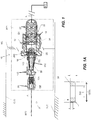
FIG. 1 is a schematic cross-sectional view of a preferred sidewall mist nozzle in a horizontal orientation. -
FIG. 1A is a cross-sectional view of an orifice insert used in the nozzle ofFIG. 1 . -
FIG. 1B is a front view of the nozzle ofFIG. 1 . -
FIG. 2 is a perspective view of a preferred diffuser for use in the nozzle ofFIG. 1 . -
FIG. 3 is a side view of the preferred diffuser inFIG. 2 . -
FIG. 4 is an end view of the preferred diffuser inFIG. 2 . -
FIG. 5 is another end view of the preferred diffuser inFIG. 2 . -
FIG. 6 is a cross-sectional plan view of the diffuser ofFIG. 4 along line VI--VI. -
FIG. 7 is another cross-sectional plan view of the diffuser ofFIG. 4 along line VII-VII. - Schematically shown in
FIGS. 1 and1B is a preferredfluid mist nozzle 10 installed in a horizontal arrangement to provide fire protection to an occupancy O defined by a floor FLR below thenozzle 10, a ceiling CLG above thenozzle 10 and one or more walls WL extending between the floor FLR and the ceiling CLG. In the preferred horizontal or sidewall arrangement, thenozzle 10 is mounted through a hole in the wall WL and coupled or connected to a supply line of fire fighting fluid such as, for example, water WS. Upon nozzle actuation in response to a fire, fluid droplets are generated and dispersed from thenozzle 10 in a preferred manner to provide effective wetting and cooling of the surrounding surfaces and environment. Thenozzle 10 is preferably located within a prescribed distance beneath the ceiling CLG to provide sufficient cooling at the ceiling while providing sufficient wetting of floor and wall surfaces to effectively address the fire. - The
preferred sidewall nozzle 10 includes aframe 12 having a first end for coupling to a pipe fitting of the fluid supply WS and a second end to which adiffuser 100 is mounted for generating a preferred mist distribution about the nozzle that can be used in a preferred method of fire protection. Water impacting thediffuser 100 results in the formation of droplets and various preferred directed distributions of those droplets to provide the desired cooling and wetting density. As described herein, thepreferred diffuser 100 provides for a preferably asymmetric mist distribution in which fluid droplets are retained or restricted from overly wetting the ceiling CLG and directed forward and rearward of thenozzle 10 while sufficiently distributing droplets laterally to wet the surrounding floor FLR and wall(s) WL. Accordingly, the preferred mist distribution is imbalanced with more droplets below and laterally about the nozzle with fewer droplets above the nozzle. Given the asymmetry in the preferred mist distribution, preferred embodiments of the diffuser are asymmetric to generate and distribute the desired mist for fire protection. - A
preferred frame 12 includes abody 14 defining an inlet 16, an outlet 18, and an internal passageway 20 extending between the inlet 16 and the outlet 18 along a nozzle axis A--A. The passageway 20 is dimensioned to house astrainer 22 and an orifice insert 24. Thestrainer 22 filters out debris and contaminants from the incoming fluid and the orifice insert 24 restricts the fluid path to define the discharge characteristics of the fluid. Shown inFIG. 1A is a cross-sectional view of a preferred insert 24, which defines an internal diameter DIA of the orifice insert 24 to define the discharge characteristics out of thenozzle body 14, including the pressure and/or flow characteristics to impact thediffuser 100 for generation and distribution of the firefighting mist. As is understood in the art, discharge characteristics can be quantified by a nominal K-factor of a sprinkler, which is defined as an average flow of water in gallons per minute through the internal passageway divided by a square root of pressure of water fed into the inlet end of the internal passageway in pounds per square inch gauge: Q=K√P where P represents the pressure of water fed into the inlet end of the internal passageway through the body of the sprinkler, in pounds per square inch gauge (psig); Q represents the flow of water from the outlet end of the internal passageway through the body of the sprinkler, in gallons per minute (gpm); and K represents the nominal K-factor constant in units of gallons per minute divided by the square root of pressure expressed in psig. Preferred embodiments of thenozzle 10 used herein have a nominal K-factor ranging from about 1 to about 10 GPM/(PSI)½, is more preferably less than 5 GPM/(PSI)½, and is more preferably less than 5 GPM/(PSI)½, and is more preferably less than 2 GPM/(PSI)½, for example, 1.8 GPM/(PSI)½ or 1.96 GPM/(PSI)½. It should be understood that alternative embodiments of thenozzle 10 can include aframe 12 and/or orifice insert 24 to provide a K-factor of less than 1 or greater than 10 GPM/(PSI)½, for use in combination with preferred embodiments of diffuser described herein. - The internal diameter DIA of the orifice insert 24 is preferably less than 1/3 of an inch to provide for the desired K-factor. In a preferred embodiment of the orifice insert 24, the insert is shaped as an annular disc with a preferred internal diameter DIA of 0.297 inch and a preferred outer diameter ODIA of about 1/2 inch. The internal passageway 20 of the
frame 12 is dimensioned and configured to support and house the preferred orifice insert 24 andstrainer 22 with the internal diameter of the passageway reducing from a first internal diameter D1 at the inlet 16 to smaller second diameter D2 at the outlet 18. The exterior of theframe body 14 is configured for coupling to supply piping, which can include external pipe threading and a tool engagement portion for securing the nozzle to the supply piping WS. - A
preferred frame 12 for use in thenozzle 10 is shown and described inU.S. Patent No. 5,505,383 and commercially embodied in the Type AM10 AQUAMIST nozzle, shown in Tyco Fire Products LP brochure TFP2210, entitled "Type AM10 and AM10B AQUAMIST Nozzles Non-Automatic (Open)" (Nov. 2015). Each of the cited documents is attached as Exhibit A and incorporated by reference in their entirety. Apreferred frame 12 includes an apex 26 axially spaced from the outlet 18 with a pair offrame arms 28 extending from the body to converge at the apex 26. The pair ofarms 28 are equidistantly spaced about a first bisecting plane BP1 that bisects thebody 14. Moreover, the pair ofarms 28 are aligned with one another in a second bisecting plane BP2 that bisects thebody 14 and is perpendicular to the first bisecting plane BP1. The intersection of the first and second bisecting planes BP1, BP2 is aligned along the nozzle axis A--A. - The
diffuser 100 is preferably disposed internally to theframe 12 between thebody 14 and the apex 26 and between or internal to theframe arms 28. The installeddiffuser 100 has animpact end 102 opposed to and spaced from the outlet 18 against which fluid discharged from the orifice insert 24 impacts to generate the fluid mist. Thediffuser 100 also has adischarge end 104 axially spaced from theimpact end 102 about which the generated mist disperses. The axial distance between the impact and discharge ends 102, 104 define a length or depth DP of the diffuser extending along a diffuser axis D--D aligned parallel with and preferably along the nozzle axis A--A and which is within the first bisecting plane BP1. Generally, the height H of thediffuser 100 is measured in a direction perpendicular to the nozzle axis A--A and within the first bisecting plane BP1. Preferably, the total height of the diffuser height H is less than the outlet diameter D2. The width W of thediffuser 100 is measured in a direction perpendicular to the height and in particular, measured in the direction perpendicular to the nozzle axis A--A and parallel to the second bisecting plane BP2. Thediffuser 100 is preferably mounted or secured to theframe 12 at the apex 26. Thepreferred diffuser 100 preferably includes a threadedsecurement portion 106 distally of thedischarge end 104 for engagement with the apex 26. Thediffuser 100 can be affixed by alternative means provided that the preferred diffuser can be appropriately fixed and oriented to effectively generate and disperse a mist as described herein. - Shown in
FIG. 2 is a perspective of thediffuser 100 without theframe 12 for clarity. Thediffuser 100 and in particular, theimpact end 102 is preferably asymmetric with respect to at least one of the first bisecting plane BP1 or second bisecting plane BP2. In a preferred embodiment, thediffuser 100 is preferably asymmetric with respect to the first bisecting plane BP1 and symmetric with respect to the second bisecting plane BP2. In the preferred embodiment shown, theimpact end 102 of thediffuser 100, as installed, is preferably asymmetric with respect to the second bisecting plane BP2 and symmetric about the first plane BP1. Thepreferred diffuser 100 has afirst portion 108 and asecond portion 110, spaced apart from one another to define at least one flow path orchannel 112 therebetween wherein the first andsecond portions second portion third portion 114 centered along the diffuser axis D--D to form twoflow channels third portion 114. - With respect to the embodiment of the
diffuser 100 shown inFIGS. 2-7 , the first portion of the diffuser provides a base or stage 108 from which the other portions of the diffuser are disposed. Preferably, the diffuser is formed or machined from a unitary piece of material to provide the regions and surfaces described. Alternatively, the diffuser can be formed from joining components provided the assembly provides for the portions, surfaces and flow channels described herein. Thestage 108 includes various surfaces as described in greater detail herein, which direct a generated mist laterally and forward and rearward with respect to thenozzle 10. The second portion of thediffuser 100 defines apreferred retainer portion 110 to redirect or restrict a majority of the mist to below theretainer portion 110 so as to minimize the droplet spray on the ceiling CLG. The third portion of thediffuser 100 defines apreferred wedge 114 to separate the stage andretainer portions open flow channels wedge 114 breaks the fluid discharge from the insert orifice 24 into multiple streams for the preferred distribution. As seen from the end views of thediffuser 100 shown inFIGS. 4 and 5 , the voids of thediffuser 100 are all located along the periphery of the diffuser to define its external profile. Accordingly, thediffuser 100 is preferably a solid or imperforate member having no closed form through openings or penetrations such that all fluid flow is over the external surface of thediffuser 100. - The
preferred stage 108 includes various surfaces to distribute a generated mist. In its preferred horizontal orientation theframe arms 28 and the second bisecting plane BP2 are substantially parallel to the floor FLR and ceiling CLG, as seen inFIG. 1 . Referring again toFIGS. 4 and 5 , thestage 108 includes a preferred planar upper surface 120 extending parallel to the second bisecting plane BP2 that opposes theretainer 110 to define theflow channel 112 therebetween. Thestage 108 preferably includes alower surface 122 axially spaced from the upper surface 120 to define a preferred arcuate surface, and more preferably, a concave surface defined by at least one radius of curvature R1 about an axis of curvature C1 extending parallel to the diffuser axis D--D. Preferably, the axis of curvature C1 is laterally offset from the first bisecting plane BP1. Fluid discharged from the insert orifice 24 that impacts thediffuser 100 and streams over the lowerarcuate surface 122 is preferably thrown forward of thenozzle 10. With reference toFIG. 4 , the preferred upper andlower surfaces 120, 122 of thestage 108 define a variable height HI of the stage over the width W of thediffuser 100 with the maximum height at the most lateral edges of thestage 108 and the minimum height at the mid-point of the stage. In a preferred embodiment of thediffuser 100, the maximum height HI of thestage 108 is about one half of the overall height H of thediffuser 100 and the minimum height HI of thestage 108 is about one half of the maximum height of the stage. - The
stage 108 also defines an impact face 126 at theimpact end 102 of thediffuser 100 that is symmetric about the first bisecting plane BP1. Referring toFIG. 6 , the impact face 126 includes alateral portion 128 and a preferably arcuateconcave portion 130 between thelateral portion 128 and the first bisecting plane BP1. The arcuateconcave portion 130 is defined by a radius of curvature R2 about an axis of curvature C2 extending perpendicular to the diffuser axis D--D and parallel to and offset from the first bisecting plane BP1, the lateral portion being planar and disposed perpendicular to the diffuser axis D--D. Fluid discharged from the insert orifice 24 that impacts the impact face 126 and streams over thelateral portion 128 is preferably thrown laterally and rearward of the nozzle and toward the wall WL as schematically shown inFIG. 6 . - As seen in
FIGS. 5-7 , at thedischarge end 104 of thediffuser 100, thestage 108 includes adischarge face 132 that is planar extending perpendicular to the diffuser axis and formed about thesecurement portion 106. Thestage 108 preferably includes anarcuate periphery 134 contiguous with each of the impact face 126 anddischarge face 132 of the stage. The arcuate periphery defines a preferably external convex surface defined by a radius of curvature R3 about an axis of curvature C3 extending parallel to the first bisecting plane BP1 and perpendicular to the diffuser axis D--D. - With reference to
FIGS. 1 ,2 and3 , theretainer 110 of thediffuser 100 is preferably formed as a substantially planar member that, in the installed position of thenozzle 100, is located above thestage 108. Thepreferred retainer 110 has a preferably planarupper surface 140 and alower surface 142 that includes a planar portion spaced from theupper surface 140 to define a height H2 of theretainer 110, which is preferably about 1/8 of the total diffuser height H. The preferred lowerplanar surface portion 142 of theretainer 110 is preferably opposed to the upper surface 120 of thestage 108 about the second bisecting plane BP2 to define theflow channel 112 therebetween. Moreover, the upper surface 120 of thestage 108 is preferably located closer to the second bisecting plane BP2 than thelower surface 142 of theretainer 110. The position and geometry of theretainer 110 are preferably configured to minimize or otherwise retain a generated mist of thenozzle 10 away from the ceiling CLG while providing sufficient cooling in the space between thenozzle 10 and the ceiling CLG. Theretainer 110, in combination with thestage 108, also facilitates the forward throw of the fluid mist to provide effective surface wetting below and about thenozzle 10. - Each of the
opposed surfaces 120, 142 of the respective stage andretainer components retainer 110 preferably defines the maximum depth DP of the diffuser with thestage 108 having a smaller depth DP1 preferably about 2/3 of the maximum depth. Additionally, theretainer 110 is preferably located closer to the outlet 18 of theframe body 14 than thestage 108 such that the distance from the outlet 18 of theframe 12 to theretainer 110 is smaller than the distance from the outlet 18 to thestage 108. Accordingly, in a preferred aspect, thestage 108 and theretainer 110 define a retainer depth-to-stage depth ratio (DP:DP1) that is no more than 1.5:1. In the preferred embodiment, the diffuser and itsretainer 110 define a preferred maximum depth of about 0.3 inch. Moreover, the depth of each of the opposed stage andretainer surfaces 120, 142 define preferred ratios with the height (DP:H), (DP1:H) of thediffuser 100 that preferably ranges from 1:1 to 0.5:1. More preferably, thediffuser 100 defines a preferred minimum depth to height ratio that ranges from 1:1 to 0.5:1. As seen inFIG. 4 and 5 , theretainer 110 has a width W1 that is less than the stage width W with a ratio of stage width-to-retainer width (W:W1) being no more than 1.25:1. The width of each of the opposed stage andretainer surfaces 120, 142 define preferred ratios with the depth (W:DP1), (W1:DP) of thediffuser 100 that preferably ranges from 2:1 to 1:1. More preferably, thediffuser 100 defines a preferred minimum width to depth ratio that ranges from 2:1 to 1.3:1. - The
wedge 114 spaces thestage 108 and theretainer 110 from one another to define the height of the one ormore flow paths 112. Various preferred surface geometries of thewedge 114 break up the fluid discharge from the orifice insert 24 to provide for a desired droplet size and direction of distribution. In a preferred aspect, the height of theflow path 112 is preferably about 3/8 of the overall height H of the diffuser. As seen inFIG. 3 , thewedge 114 has an overall depth DP2 that is preferably equal to the depth DP1 of thestage 108. Preferably, the height of the flow path varies with the height H3 of thewedge 114, which preferably decrease over its depth DP2 in the direction from theimpact end 102 to thedischarge end 104 of the diffuser. With the preferred variable height H3 of the wedge, theretainer 110 and itsplanar surfaces - In another preferred aspect, as seen in
FIG. 7 , thewedge 114 defines a variable width W2 over its depth DP2 in which the wedge width preferably increases in a direction from theimpact end 102 to thedischarge end 104. The width W2 of thewedge 114 is defined bylateral surfaces 144 formed about the first bisecting plane BP1. Preferably, eachlateral surface 144 includes a convex portion defined by a constant radius of curvature R4 from an axis of curvature C4 located on the opposite side of the first bisecting plane BP1 from the convexlateral surface 144. In another preferred aspect, the diffuser includes other arcuate surfaces along thewedge 114 to preferably break up fluid streams prior to mist dispersion forward of thenozzle 10. As seen inFIG. 4 , one or more concave surfaces of thewedge 114 are preferably contiguous withlower surface 142 of theretainer 108. In another preferred aspect, theconcave portion 146 increases in height in the direction from theimpact end 102 to thedischarge end 104, as seen inFIG. 3 . Alternatively or additionally, the radius of curvature of theconcave portion 146 can vary over the depth of the diffuser or can be constant. Accordingly, in a preferred embodiment of thediffuser 100 in which thewedge 114 defines internal surfaces of theopen flow channels - The
diffuser 100 includes other surface features to direct fluid streams for the desired mist distribution. For example, one or more chamfered surfaces provide for transitional surfaces to direct fluid streams to the various regions of the diffuser for distribution in a desired manner. With reference toFIG. 2 , the stage can include onecentral chamfer 150 and twolateral chamfers 152 to direct fluid stream toward the arcuate lower surface. - Shown in
FIG. 5 , two chamfered surfaces 154 are disposed at the discharge end of theretainer 110 along theupper surface 140. - The
preferred nozzle 10 is preferably configured as an automatic device which generates a firefighting mist in response to a stimulus. With reference toFIG. 1 , thenozzle 10 has an unactuated state in which a sealingassembly 200 is disposed within the outlet 18 to prevent fluid discharge from the outlet. The sealingassembly 200 is supported in the outlet 18 by a thermallyresponsive trigger device 202 that fractures in response to an predetermined level of heat to release the sealingassembly 200 and permit the discharge of fluid from theframe body 14. The thermally responsive device is preferably embodied as a thermally responsivefrangible bulb 202 which breaks in response to a threshold level of heat. - The
preferred diffuser 100 provides for abulb seat 160 formed and centered along theimpact end 102 of thediffuser 100. Shown inFIGS. 2 ,3 and 4 are side and elevated views of thebulb seat formation 160. Thebulb seat 160 is preferably a concave substantially centered along the diffuser axis D-D for alignment with the preferably threadedsecurement portion 106 and nozzle axis A--A. Accordingly, axial translation of thediffuser 100 with respect to the outlet 18 of theframe body 14 can load thebulb 202 against theseal assembly 200 to seal outlet of thenozzle 100 and place the nozzle in an unactuated state. - While the present invention has been disclosed with reference to certain embodiments, numerous modifications, alterations and changes to the described embodiments are possible without departing from the sphere and scope of the present invention, as defined in the appended claims. Accordingly, it is intended that the present invention not be limited to the described embodiments, but that it has the full scope defined by the language of the following claims, and equivalents thereof.
-
Clause 1. A fluid nozzle comprising: - a frame having a body defining an inlet, an outlet and a passageway extending between the inlet and the outlet along a nozzle axis; and
- an imperforate diffuser spaced from the outlet having an impact end and a discharge end spaced apart from one another to define a depth of the diffuser extending along a diffuser axis aligned coaxially aligned along the nozzle axis and within a bisecting plane of the diffuser, the diffuser defining a height in a direction perpendicular to the diffuser axis within the bisecting plane, the diffuser having a minimum depth-to-height ratio ranging from 1:1 to 0.5:1, the imperforate diffuser including:
- a stage;
- a retainer; and
- a wedge disposed between the retainer and the stage to define an external profile including a pair of open end flow channels formed about the wedge, each open end flow channel having an internal surface extending from the impact end to the discharge end.
- Clause 2. The mist nozzle of
Clause 1, wherein the stage includes a planar surface extending perpendicular to a bisecting plane that bisects the diffuser and the frame body, the diffuser including an arcuate surface opposite the planar surface. - Clause 3. The fluid nozzle of
Clause 1, wherein the retainer has a first surface defining a first depth in a direction of the diffuser axis, the stage having a second surface defining a second depth in the direction of the diffuser axis, the first and second surfaces being spaced apart to define the pair of flow channels therebetween, each of the first depth and the second depth defining a depth-to-diffuser height ratio that ranges from 1:1 to 0.5:1. - Clause 4. The fluid nozzle of any one of the above Clauses, wherein the wedge extends between the impact end and the discharge end and has a variable width over the depth of the diffuser such that the wedge variable width increases in the direction of the diffuser axis from the impact end to the discharge end.
- Clause 5. The fluid nozzle of any one of the above Clauses, wherein the wedge has a variable height over the depth of the diffuser such that a wedge height decreases in a direction of the diffuser axis from the impact end to the discharge end.
- Clause 6. The fluid nozzle of any one of the above Clauses wherein, the internal surface of each channel includes a convex portion and a concave portion.
- Clause 7. The fluid nozzle of Clause 6, wherein the convex portion extends with a decreasing height from the impact end to the discharge end, the concave portion of the wedge extends with an increasing height from the impact end to the discharge end.
- Clause 8. The fluid nozzle of Clause 6, wherein each convex portion is defined by a constant radius from an axis of curvature located on an opposite side of the first bisecting plane from the convex portion.
- Clause 9. The fluid nozzle of any one of the above Clauses, wherein the stage includes a planar upper surface extending parallel to the second bisecting plane and a lower surface axially spaced from the planar upper surface to define a variable height of the stage over the width of the diffuser.
-
Clause 10. The fluid nozzle of Clause 9, wherein the lower surface of the stage includes an arcuate surface defining at least one radius of curvature about an axis of curvature extending parallel to the diffuser axis the arcuate surface being symmetrical about the bisecting plane. - Clause 11. The fluid nozzle of
Clause 10, wherein the axis of curvature is laterally offset from the bisecting plane. -
Clause 12. The fluid nozzle of any one of the above Clauses, wherein the stage defines an impact face at the impact end of the diffuser that symmetric about the bisecting plane, the impact face including a lateral portion and an arcuate concave portion between the lateral portion and the first bisecting plane, the arcuate concave portion being defined by a radius of curvature about an axis of curvature extending perpendicular to the diffuser axis and parallel to and offset from the first bisecting plane, the lateral portion being planar and disposed perpendicular to the diffuser axis. - Clause 13. The fluid nozzle of claim any one of the above Clauses, wherein the stage includes a discharge face at the discharge end of the diffuser, the discharge face of the stage being planar extending perpendicular to the diffuser axis, the stage including an arcuate periphery contiguous with each of the impact face and discharge face of the stage, the arcuate periphery defined by a radius of curvature about an axis of curvature extending parallel to the bisecting plane, the arcuate periphery including at least one chamfer contiguous with the lower surface.
-
Clause 14. The fluid nozzle of any one of the above Clauses, wherein the retainer is a planar member disposed at an angle with respect to the diffuser axis, the planar member being axially spaced from the planar upper surface of the stage, the retainer defining a width that is less than the stage width with a ratio of stage width-to-retainer width being no more than 1.25:1, the stage and the retainer defining a retainer depth-to-stage depth ratio that is no more than 1.5:1. - Clause 15. The fluid nozzle of any one of the above Clauses, wherein a distance from the outlet of the frame to the retainer is smaller than a distance from the outlet to the stage.
- Clause 16. The fluid nozzle of any one of the above Clauses, wherein the retainer has an upper surface and a lower surface defining a height of the retainer in between, the upper surface including a pair of chamfers along the upper surface.
- Clause 17. The fluid nozzle of any one of the above Clauses, wherein the wedge extends from the impact end to the discharge end.
- Clause 18. The fluid nozzle of any one of the above Clauses, wherein the diffuser includes a seat formed at the impact end of the diffuser for supporting a thermally responsive trigger between the outlet and the diffuser.
- Clause 19. The fluid nozzle of Clause 18, further comprising a thermally responsive bulb disposed within the diffuser seat for supporting a seal.
- Clause 20. The fluid nozzle of any one of the above Clauses, wherein the diffuser is disposed internal to the nozzle frame.
- Clause 21. The fluid nozzle of any one of the above Clauses, further comprising an annular orifice member disposed along the passageway between the inlet and the outlet, the annular orifice member defining a nominal K-factor of less than 2.
-
Clause 22. A method of fire protection of an occupancy using a sidewall mist nozzle, the method comprising: - providing a fluid mist nozzle frame for mounting in a horizontal arrangement along a wall between a ceiling and a floor of the occupancy, the frame having a body defining an inlet for connection to a fluid supply, an outlet, and a passageway extending between the inlet and the outlet along a nozzle axis; and
- spacing an imperforate diffuser from the outlet having a minimum depth to height ratio ranging from 1:1 to 0.5:1 and an external profile including a pair of open end flow channels formed about the diffuser to provide a mist distribution of a fluid discharge from the frame body in the horizontal arrangement with the mist distribution having more droplets below and laterally about the nozzle and fewer droplets above the nozzle so as to wet the floor and wall while restricting droplets from wetting the ceiling.
-
Clause 23. The method ofClause 22, wherein spacing the diffuser including disposing a diffuser having a stage to throw the fluid discharge forward, laterally and rearward of the nozzle; a retainer to restrict droplets above the nozzle; and a wedge disposed between the retainer and the stage to define an external profile including a pair of open end flow channels formed about the wedge, each open end flow channel having an internal surface extending from an impact end to a discharge end of the diffuser.
Claims (24)
- A fluid mist nozzle comprising:a frame having a body defining an inlet having, an outlet and a passageway extending between the inlet and the outlet along a nozzle axis, the frame including an apex axially spaced from the outlet with a pair of frame arms extending from the body to the apex, the pair of arms being equidistantly spaced about a first bisecting plane that bisects the body, the pair of arms being aligned in a second bisecting plane that bisects the body and is perpendicular to the first bisecting plane to define an intersection of the first and second bisecting planes being aligned along the nozzle axis;a diffuser disposed internally to the frame between the body and the apex, the diffuser having an impact end opposed to and spaced from the outlet and a discharge end axially spaced from the impact end along a diffuser axis aligned parallel with the nozzle axis, the impact end being asymmetric with respect to at least one of the first bisecting plane or second bisecting plane.
- The fluid mist nozzle of claim 1, wherein the diffuser is asymmetric about the second bisecting plane, the diffuser including a first portion and a second portion, spaced apart from one another to define at least one flow channel therebetween wherein the first and second portions are unequally spaced about the second bisecting plane.
- The fluid mist nozzle of claim 2, wherein the diffuser is symmetric about the first bisecting plane, the diffuser including a third portion centered along the nozzle axis that spaces the first portion from the second portion to form the at least one flow channel as being two flow channels about the third portion.
- The fluid mist nozzle of claim 1, wherein the diffuser is symmetrical about the first bisecting plane defining a height measured in a direction parallel to the first bisecting plane and perpendicular to the nozzle axis, the diffuser defining a width measured in a direction parallel to the second bisecting plane and perpendicular to the nozzle axis, the diffuser including a stage member and a retainer affixed to the stage, the stage member and retainer being disposed from one another about the second bisecting plane to define at least one flow channel therebetween.
- The fluid mist nozzle of claim 4, wherein the retainer has a first surface defining a first depth in a direction of the diffuser axis, the stage having a second surface defining a second depth in the direction of the diffuser axis, the first and second surfaces disposed from one another about the second bisecting plane to define the at least one flow channel therebetween, each of the first depth and the second depth defining a depth-to-diffuser height ratio that ranges from 1:1 to 0.5:1.
- The fluid mist nozzle of claim 5, wherein the diffuser includes a wedge disposed between the retainer and the stage, the wedge extending between the impact end and the discharge end and having a variable width over the depth of the diffuser such that the wedge variable width increases in the direction of the diffuser axis from the impact end to the discharge end.
- The fluid mist nozzle of claim 6, wherein the wedge has a variable height over the depth of the diffuser such that the wedge variable height decreases in the direction of the diffuser axis from the impact end to the discharge end.
- The fluid mist nozzle of claim 6, wherein the wedge includes lateral surfaces formed about the first bisecting plane, each lateral surface including a convex portion and a concave portion with respect to an axis spaced from the lateral surface and extending between the retainer and the stage, the convex portion extending with a decreasing height from the impact end to the discharge end, the concave portion extending with an increasing height from the impact end to the discharge end.
- The fluid mist nozzle of claim 8, wherein each convex portion is defined by a constant radius from an axis of curvature located on an opposite side of the first bisecting plane from the convex portion.
- The fluid mist nozzle of claim 4, wherein the stage includes a planar upper surface extending parallel to the second bisecting plane and a lower surface axially spaced from the upper surface to define a variable height of the stage over the width of the diffuser.
- The fluid mist nozzle of claim 10, wherein the lower surface of the stage includes an arcuate surface defining at least one radius of curvature about an axis of curvature extending parallel to the diffuser axis the arcuate surface being symmetrical about the first bisecting plane.
- The fluid mist nozzle of claim 11, wherein the axis of curvature is laterally offset from the first bisecting plane.
- The fluid mist nozzle of claim 4, wherein the stage defines an impact face at the impact end of the diffuser that is symmetric about the first bisecting plane, the impact face including a lateral portion and an arcuate concave portion between the lateral portion and the first bisecting plane, the arcuate concave portion being defined by a radius of curvature about an axis of curvature extending perpendicular to the diffuser axis and parallel to and offset from the first bisecting plane, the lateral portion being planar and disposed perpendicular to the diffuser axis.
- The fluid mist nozzle of claim 13, wherein the stage includes a discharge face at the discharge end of the diffuser, the discharge face of the stage being planar extending perpendicular to the diffuser axis, the stage including an arcuate periphery contiguous with each of the impact face and discharge face of the stage, the arcuate periphery defined by a radius of curvature about an axis of curvature extending parallel to the bisecting plane, the arcuate periphery including at least one chamfer contiguous with a lower surface of the periphery.
- The fluid mist nozzle of claim 4, wherein the retainer is a planar member disposed at an angle with respect to the diffuser axis, the planar member being spaced from the stage, the retainer defining a width that is less than a stage width with a ratio of stage width-to-retainer width being no more than 1.25:1, the stage and the retainer defining a retainer depth-to-stage depth ratio that is no more than 1.5:1.
- The fluid mist nozzle of any one of claims 4 to 15, wherein the distance from the outlet of the frame to the retainer is smaller than the distance from the outlet to the stage.
- The fluid mist nozzle of any one of claims 4 to 16, wherein the retainer has an upper surface and a lower surface defining a height of the retainer in between, the upper surface including a pair of chamfers along the upper surface.
- The fluid mist nozzle of any one of claims 4 to 16, wherein the wedge extends from the impact end to the discharge end.
- The fluid mist nozzle of any one of the above claims, wherein the diffuser includes a seat formed at the impact end of the diffuser for supporting a thermally responsive trigger between the outlet and the diffuser.
- The fluid mist nozzle of claim 19, further comprising a thermally responsive bulb disposed within the diffuser seat for supporting a seal.
- The fluid mist nozzle of any one of claims 1 to 20, further comprising an annular orifice member disposed along the passageway between the inlet and the outlet, the inlet has a first diameter, the outlet has a second diameter and the annular orifice member defines an internal diameter that is less than the second diameter to defining a nominal K-factor of less than 2.
- A method of fire protection of an occupancy using a sidewall mist nozzle, the method comprising:providing a fluid mist nozzle frame for mounting in a horizontal arrangement along a wall between a ceiling and a floor of the occupancy, the frame having a body defining an inlet for connection to a fluid supply, an outlet, and a passageway extending between the inlet and the outlet along a nozzle axis, the frame including an apex axially spaced from the outlet with a pair of frame arms extending from the body to the apex, the pair of arms being equidistantly spaced about a first bisecting plane that bisects the body, the pair of arms being aligned in a second bisecting plane that bisects the body, perpendicular to the first bisecting plane to define an intersection of the first and second bisecting planes being aligned along the nozzle axis; anddisposing an asymmetric diffuser internally to the frame between the body and the apex to provide an asymmetric mist distribution of a fluid discharge from the frame body in the horizontal arrangement with the asymmetric distribution having more droplets below and laterally about the nozzle with fewer droplets above the nozzle so as to wet the floor and wall while restricting droplets from wetting the ceiling.
- The method of claim 22, wherein the disposing the asymmetric diffuser includes disposing the diffuser symmetrically about the first plane with the diffuser including a stage member to throw the fluid discharge forward, laterally and rearward of the nozzle and a retainer disposed from the stage member to restrict droplets above the nozzle.
- The method of claim 23, wherein the disposing the asymmetric diffuser includes disposing a wedge between the retainer and the stage to break the fluid discharge into multiple streams.
Applications Claiming Priority (2)
| Application Number | Priority Date | Filing Date | Title |
|---|---|---|---|
| US201762611976P | 2017-12-29 | 2017-12-29 | |
| US201762611944P | 2017-12-29 | 2017-12-29 |
Publications (1)
| Publication Number | Publication Date |
|---|---|
| EP3508256A1 true EP3508256A1 (en) | 2019-07-10 |
Family
ID=65011802
Family Applications (1)
| Application Number | Title | Priority Date | Filing Date |
|---|---|---|---|
| EP18248153.1A Pending EP3508256A1 (en) | 2017-12-29 | 2018-12-28 | Fluid mist nozzle and methods with an asymmetric diffuser |
Country Status (1)
| Country | Link |
|---|---|
| EP (1) | EP3508256A1 (en) |
Citations (5)
| Publication number | Priority date | Publication date | Assignee | Title |
|---|---|---|---|---|
| US5505383A (en) | 1994-11-02 | 1996-04-09 | Grinnell Corporation | Fire protection nozzle |
| US6098718A (en) * | 1997-12-03 | 2000-08-08 | Senju Sprinkler Company Limited | Horizontal sidewall sprinkler head |
| US6367559B1 (en) * | 1998-12-29 | 2002-04-09 | The Viking Corporation | Double-blade deflector for side wall sprinkler |
| WO2010078559A1 (en) * | 2009-01-02 | 2010-07-08 | Tyco Fire Products Lp | Mist type fire protection devices, systems and methods |
| WO2014151977A2 (en) * | 2013-03-14 | 2014-09-25 | Tyco Fire Products Lp | Fire protection sprinkler assembly |
-
2018
- 2018-12-28 EP EP18248153.1A patent/EP3508256A1/en active Pending
Patent Citations (5)
| Publication number | Priority date | Publication date | Assignee | Title |
|---|---|---|---|---|
| US5505383A (en) | 1994-11-02 | 1996-04-09 | Grinnell Corporation | Fire protection nozzle |
| US6098718A (en) * | 1997-12-03 | 2000-08-08 | Senju Sprinkler Company Limited | Horizontal sidewall sprinkler head |
| US6367559B1 (en) * | 1998-12-29 | 2002-04-09 | The Viking Corporation | Double-blade deflector for side wall sprinkler |
| WO2010078559A1 (en) * | 2009-01-02 | 2010-07-08 | Tyco Fire Products Lp | Mist type fire protection devices, systems and methods |
| WO2014151977A2 (en) * | 2013-03-14 | 2014-09-25 | Tyco Fire Products Lp | Fire protection sprinkler assembly |
Non-Patent Citations (1)
| Title |
|---|
| TYPE AM10 AND AM10B AQUAMIST NOZZLES NON-AUTOMATIC (OPEN, November 2015 (2015-11-01) |
Similar Documents
| Publication | Publication Date | Title |
|---|---|---|
| US11612775B2 (en) | CPVC sprinkler assembly with support member | |
| CA2482603C (en) | Sprinkler head with improved flow | |
| RU2485986C1 (en) | Kochetov's radial-flow vortex nozzle | |
| EP2012881B1 (en) | Extended coverage horizontal sidewall sprinkler | |
| EP0737111B1 (en) | Fire protection nozzle | |
| RU2533099C1 (en) | Kochetov's centrifugal vortex atomiser | |
| US6964307B1 (en) | Sprinklers | |
| AU2000263289A1 (en) | Sprinklers | |
| EP2969047B1 (en) | Fire protection device and method for fire protection of an industrial oil cooker | |
| JP6242500B2 (en) | Fire extinguishing fluid nozzle system for stationary fire extinguishing systems with a throttling ring, and throttling rings for fire extinguishing fluid nozzles and fire extinguishing fluid nozzles | |
| US20230044995A1 (en) | Firefighting system for an extractor duct, in particular of a cooking zone | |
| CA2679002C (en) | Ambient mist head | |
| US9573006B2 (en) | Fire extinguishing assembly for transforming a liquid to a liquid mist | |
| JP2009112586A (en) | Sprinkler head | |
| WO2018022812A1 (en) | Filter adapter | |
| PL222023B1 (en) | Spin-jet head open for the manufacture of water mist | |
| HK1128437B (en) | Extended coverage horizontal sidewall sprinkler | |
| JP2014234835A (en) | Orifice containing joint and sprinkler fire-fighting facility employing the same |
Legal Events
| Date | Code | Title | Description |
|---|---|---|---|
| PUAI | Public reference made under article 153(3) epc to a published international application that has entered the european phase |
Free format text: ORIGINAL CODE: 0009012 |
|
| STAA | Information on the status of an ep patent application or granted ep patent |
Free format text: STATUS: THE APPLICATION HAS BEEN PUBLISHED |
|
| AK | Designated contracting states |
Kind code of ref document: A1 Designated state(s): AL AT BE BG CH CY CZ DE DK EE ES FI FR GB GR HR HU IE IS IT LI LT LU LV MC MK MT NL NO PL PT RO RS SE SI SK SM TR |
|
| AX | Request for extension of the european patent |
Extension state: BA ME |
|
| RIN1 | Information on inventor provided before grant (corrected) |
Inventor name: JUTRAS, IAN Inventor name: MINER, EMILY Inventor name: CUTTING, SEAN E. |
|
| STAA | Information on the status of an ep patent application or granted ep patent |
Free format text: STATUS: REQUEST FOR EXAMINATION WAS MADE |
|
| 17P | Request for examination filed |
Effective date: 20191212 |
|
| RBV | Designated contracting states (corrected) |
Designated state(s): AL AT BE BG CH CY CZ DE DK EE ES FI FR GB GR HR HU IE IS IT LI LT LU LV MC MK MT NL NO PL PT RO RS SE SI SK SM TR |
|
| STAA | Information on the status of an ep patent application or granted ep patent |
Free format text: STATUS: EXAMINATION IS IN PROGRESS |
|
| 17Q | First examination report despatched |
Effective date: 20221116 |
|
| RAP3 | Party data changed (applicant data changed or rights of an application transferred) |
Owner name: TYCO FIRE PRODUCTS LP |