EP3508159B1 - Flexible surgical instrument system with prepositioned drive input - Google Patents
Flexible surgical instrument system with prepositioned drive input Download PDFInfo
- Publication number
- EP3508159B1 EP3508159B1 EP17845460.9A EP17845460A EP3508159B1 EP 3508159 B1 EP3508159 B1 EP 3508159B1 EP 17845460 A EP17845460 A EP 17845460A EP 3508159 B1 EP3508159 B1 EP 3508159B1
- Authority
- EP
- European Patent Office
- Prior art keywords
- structural
- proximal
- distal
- fixing plate
- driving
- Prior art date
- Legal status (The legal status is an assumption and is not a legal conclusion. Google has not performed a legal analysis and makes no representation as to the accuracy of the status listed.)
- Active
Links
Images





Classifications
-
- A—HUMAN NECESSITIES
- A61—MEDICAL OR VETERINARY SCIENCE; HYGIENE
- A61B—DIAGNOSIS; SURGERY; IDENTIFICATION
- A61B34/00—Computer-aided surgery; Manipulators or robots specially adapted for use in surgery
- A61B34/30—Surgical robots
-
- A—HUMAN NECESSITIES
- A61—MEDICAL OR VETERINARY SCIENCE; HYGIENE
- A61B—DIAGNOSIS; SURGERY; IDENTIFICATION
- A61B17/00—Surgical instruments, devices or methods
-
- A—HUMAN NECESSITIES
- A61—MEDICAL OR VETERINARY SCIENCE; HYGIENE
- A61B—DIAGNOSIS; SURGERY; IDENTIFICATION
- A61B17/00—Surgical instruments, devices or methods
- A61B17/00234—Surgical instruments, devices or methods for minimally invasive surgery
-
- A—HUMAN NECESSITIES
- A61—MEDICAL OR VETERINARY SCIENCE; HYGIENE
- A61B—DIAGNOSIS; SURGERY; IDENTIFICATION
- A61B34/00—Computer-aided surgery; Manipulators or robots specially adapted for use in surgery
- A61B34/70—Manipulators specially adapted for use in surgery
- A61B34/71—Manipulators operated by drive cable mechanisms
-
- A—HUMAN NECESSITIES
- A61—MEDICAL OR VETERINARY SCIENCE; HYGIENE
- A61B—DIAGNOSIS; SURGERY; IDENTIFICATION
- A61B17/00—Surgical instruments, devices or methods
- A61B17/28—Surgical forceps
- A61B17/29—Forceps for use in minimally invasive surgery
-
- A—HUMAN NECESSITIES
- A61—MEDICAL OR VETERINARY SCIENCE; HYGIENE
- A61B—DIAGNOSIS; SURGERY; IDENTIFICATION
- A61B17/00—Surgical instruments, devices or methods
- A61B17/00234—Surgical instruments, devices or methods for minimally invasive surgery
- A61B2017/00292—Surgical instruments, devices or methods for minimally invasive surgery mounted on or guided by flexible, e.g. catheter-like, means
-
- A—HUMAN NECESSITIES
- A61—MEDICAL OR VETERINARY SCIENCE; HYGIENE
- A61B—DIAGNOSIS; SURGERY; IDENTIFICATION
- A61B17/00—Surgical instruments, devices or methods
- A61B17/00234—Surgical instruments, devices or methods for minimally invasive surgery
- A61B2017/00292—Surgical instruments, devices or methods for minimally invasive surgery mounted on or guided by flexible, e.g. catheter-like, means
- A61B2017/003—Steerable
-
- A—HUMAN NECESSITIES
- A61—MEDICAL OR VETERINARY SCIENCE; HYGIENE
- A61B—DIAGNOSIS; SURGERY; IDENTIFICATION
- A61B17/00—Surgical instruments, devices or methods
- A61B17/00234—Surgical instruments, devices or methods for minimally invasive surgery
- A61B2017/00292—Surgical instruments, devices or methods for minimally invasive surgery mounted on or guided by flexible, e.g. catheter-like, means
- A61B2017/003—Steerable
- A61B2017/00305—Constructional details of the flexible means
- A61B2017/00314—Separate linked members
-
- A—HUMAN NECESSITIES
- A61—MEDICAL OR VETERINARY SCIENCE; HYGIENE
- A61B—DIAGNOSIS; SURGERY; IDENTIFICATION
- A61B17/00—Surgical instruments, devices or methods
- A61B17/00234—Surgical instruments, devices or methods for minimally invasive surgery
- A61B2017/00292—Surgical instruments, devices or methods for minimally invasive surgery mounted on or guided by flexible, e.g. catheter-like, means
- A61B2017/003—Steerable
- A61B2017/00318—Steering mechanisms
-
- A—HUMAN NECESSITIES
- A61—MEDICAL OR VETERINARY SCIENCE; HYGIENE
- A61B—DIAGNOSIS; SURGERY; IDENTIFICATION
- A61B17/00—Surgical instruments, devices or methods
- A61B17/00234—Surgical instruments, devices or methods for minimally invasive surgery
- A61B2017/00292—Surgical instruments, devices or methods for minimally invasive surgery mounted on or guided by flexible, e.g. catheter-like, means
- A61B2017/003—Steerable
- A61B2017/00318—Steering mechanisms
- A61B2017/00323—Cables or rods
-
- A—HUMAN NECESSITIES
- A61—MEDICAL OR VETERINARY SCIENCE; HYGIENE
- A61B—DIAGNOSIS; SURGERY; IDENTIFICATION
- A61B17/00—Surgical instruments, devices or methods
- A61B17/00234—Surgical instruments, devices or methods for minimally invasive surgery
- A61B2017/00292—Surgical instruments, devices or methods for minimally invasive surgery mounted on or guided by flexible, e.g. catheter-like, means
- A61B2017/00336—Surgical instruments, devices or methods for minimally invasive surgery mounted on or guided by flexible, e.g. catheter-like, means with a protective sleeve, e.g. retractable or slidable
-
- A—HUMAN NECESSITIES
- A61—MEDICAL OR VETERINARY SCIENCE; HYGIENE
- A61B—DIAGNOSIS; SURGERY; IDENTIFICATION
- A61B17/00—Surgical instruments, devices or methods
- A61B17/28—Surgical forceps
- A61B17/29—Forceps for use in minimally invasive surgery
- A61B2017/2926—Details of heads or jaws
- A61B2017/2932—Transmission of forces to jaw members
-
- A—HUMAN NECESSITIES
- A61—MEDICAL OR VETERINARY SCIENCE; HYGIENE
- A61B—DIAGNOSIS; SURGERY; IDENTIFICATION
- A61B34/00—Computer-aided surgery; Manipulators or robots specially adapted for use in surgery
- A61B34/30—Surgical robots
- A61B2034/301—Surgical robots for introducing or steering flexible instruments inserted into the body, e.g. catheters or endoscopes
Definitions
- the present invention relates to a flexible surgical instrument system with a front drive input, belonging to the field of medical instruments.
- Multi-port laparoscopic minimally invasive surgery has occupied an important position in surgery because of its small incision and rapid postoperative recovery.
- the existing da Vinci surgical robot of the Intuitive Surgical, Inc. assists doctors in completing the multi-port laparoscopic minimally invasive surgery and has achieved great commercial success.
- a distal structure of the existing surgical instrument mainly consists of multiple rods articulated in series, and is driven by a pulling force from a steel wire rope, so that the surgical instrument can turn at a hinge joint. Since the steel wire rope has to be continuously tensioned by a pulley, this driving method has difficulty in further miniaturizing the surgical instrument, and also has difficulty in further improving the moving performance of the instrument.
- the Intuitive Surgical, Inc. has recently introduced a da Vinci Single-Site surgical robot, in which the original rigid surgical instrument is modified into a semi-rigid surgical instrument and a prebent sleeve is additionally provided so as to improve the moving performance of the surgical instrument to a certain extent, it still cannot fundamentally solve the problems faced by the traditional microsurgical instruments.
- the document CN105856213A discloses a high-redundancy multi-degree-of-freedom flexible mechanical arm system.
- the system comprises two mechanical arm modules that are nested together and can move relative to each other.
- Each single-arm manipulator module has three degrees of freedom, two bending degrees of freedom and one degree of feed freedom, so this flexible manipulator system will have six degrees of freedom.
- Each dexterous arm has a hybrid mechanical architecture comprised of a two-segment continuum robot.
- an object of the present invention is to provide a flexible surgical instrument system with a front drive input, which can be better applied to a surgical robot system that passes through a natural orifice of human body or a single surgical incision and performs an operation.
- a flexible surgical instrument system with a front drive input comprising a flexible continuous body structure and a driving unit
- the flexible continuous body structure comprises a distal structural body, a proximal structural body and a middle connecting body
- the distal structural body comprises at least one distal structural segment
- the distal structural segment comprises distal spacing disks, a distal fixing disk and structural backbones
- the proximal structural body comprises proximal structural segments having the same number as the number of distal structural segments, and the proximal structural segment comprises proximal spacing disks, a proximal fixing disk and structural backbones
- the middle connecting body comprises two channel fixing plates and a structural backbone guide channel provided between the two channel fixing plates
- the structural backbones of the distal structural segment are securely connected, in one-to-one correspondence, to or are the same as the structural backbones of the proximal structural segment, one end of each of the structural backbones
- the distal structural body is externally covered with an envelope, a front end of the envelope is securely connected to a surgical end effector, and a rear end of the envelope is connected to a rotary driving mechanism in the driving unit;
- the rotary driving mechanism comprises a rotary sleeve rotatably supported at a front side of the driving unit fixing plate, and a front end of the rotary sleeve is securely connected to the envelope; and the front side of the driving unit fixing plate is further provided with a rotary shaft, a pair of gears meshing with each other are provided on the rotary shaft and the rotary sleeve, and a male coupling directly or indirectly connected to an output shaft of a motor is securely connected to a front end of the rotary shaft.
- the number of the proximal structural segments is equal to the number of the distal structural segments.
- the linear motion mechanism comprises a threaded rod rotatably arranged between the driving unit fixing plate and the channel fixing plate, a shaft securely arranged between the driving unit fixing plate and the channel fixing plate, and a slider slidably connected to the shaft and threadedly fitted with the threaded rod; and the driving backbone is securely connected to the slider.
- the threaded rods pass through the driving unit fixing plate, a gear is securely connected to the threaded rod at a front side of the driving unit fixing plate, every two of the threaded rods being a group; a pair of the driving backbones are securely connected to the slider on one group of the threaded rods; and the gears on one group of the threaded rods meshes with each other, and a male coupling directly or indirectly connected to an output shaft of a motor is securely connected to a front end of one of the threaded rods in one group of the threaded rods.
- the linear motion mechanism comprises double-head threaded rods rotatably arranged between the driving unit fixing plate and the channel fixing plate, and shafts securely arranged between the driving unit fixing plate and the channel fixing plate, and two threaded sections of the double-head threaded rod are respectively connected to a slider by a threaded fit, each of the sliders being slidably connected to one of the shafts; a pair of the driving backbones are respectively securely connected to the two sliders located on the same double-head threaded rod; and the double-head threaded rod passes through the driving unit fixing plate, and a front end of the double-head threaded rod is securely connected to a male coupling directly or indirectly connected to an output shaft of a motor.
- a driving backbone guide channel is provided between the two channel fixing plates, and the driving backbone passes through the driving backbone guide channel.
- the structural backbones on the distal structural segment away from the middle connecting body pass through the distal fixing disk and the distal spacing disks on the distal structural segment near the middle connecting body, or when the distal structural body comprises two distal structural segments, and the structural backbones on the distal structural segment near the middle connecting body are elastic elongated tubes, the structural backbones on the distal structural segment away from the middle connecting body pass through the interior of the structural backbones on the distal structural segment near the middle connecting body; and when the proximal structural body comprises two proximal structural segments, the structural backbones on the proximal structural segment away from the middle connecting body pass through the proximal fixing disk and the proximal spacing disks on the proximal structural segment near the middle connecting body, or when the proximal structural body comprises two proximal structural segments, and the structural backbones on the proximal structural segment near the middle connecting body are elastic elongated tubes, the structural backbones on the proximal structural segment away from the middle connecting body
- a front end of the distal structural body is provided with a surgical end effector, a actuation wire of the surgical end effector passes through the distal structural body, and the other end of the actuation wire is connected to a surgical end effector driving mechanism which is located on the channel fixing plate and is used for converting a rotary motion input into a linear motion output.
- the surgical end effector driving mechanism comprises a base securely connected to the channel fixing plate, a connecting rod is rotatably connected to the base, one end of the connecting rod is connected to a first slider, the first slider is slidably connected to a first shaft arranged on the base, and the actuation wire of the surgical end effector is securely connected to the first slider; the other end of the connecting rod is connected to a second slider, and the second slider is slidably connected to a second shaft arranged on the channel fixing plate; and a driving threaded rod is rotatably supported on the driving unit fixing plate, a front end of the driving threaded rod is provided with a male coupling directly or indirectly connected to an output shaft of a motor, a third slider is connected to the driving threaded rod by a threaded fit, the third slider is slidably connected to a third shaft arranged between the driving unit fixing plate and the channel fixing plate, and the third slider is connected to the second slider by means of a driving rod.
- the flexible surgical instrument system further comprises a shell, a sterile barrier, a motor assembly and a linear module, wherein the driving unit fixing plate and the channel fixing plates are all securely connected to the shell, and the proximal structural body, the middle connecting body and the driving unit are all located inside the shell; a front end of the shell is connected to the motor assembly by means of the sterile barrier; and the linear module comprises a support, a motor securely connected to the support, and a linear feed mechanism securely connected to an output shaft of the motor, an output end of the linear feed mechanism is securely connected to a housing of the motor assembly, and the motor drives the motor assembly by means of the linear feed mechanism to drive the flexible continuous body structure and the driving unit to perform a linear motion by means of the sterile barrier.
- the linear feed mechanism comprises a lead screw rotatably connected to the support, the lead screw is sheathed with a slider which is threadedly fitted with the lead screw, a linear sliding groove is provided on the support, and the slider is slidably arranged in the linear sliding groove; and an output shaft of the motor is securely connected to the lead screw by means of a coupling.
- the flexible surgical instrument system further comprises a shell, wherein the driving unit fixing plate and the channel fixing plates are all securely connected to the shell, the proximal structural body, the middle connecting body and the driving unit are all located inside the shell, a front end of the shell is connected to a motor assembly by means of a sterile barrier, the sterile barrier comprises a cover and a female coupling rotatably arranged on the cover, a rear end of the female coupling is connected to the male coupling, a front end of the female coupling is connected to a motor output shaft of the motor assembly by means of another male coupling, and the periphery of the cover is connected to a sterile membrane.
- a flexible continuous body structure comprising a proximal structural body, a middle connecting body and a distal structural body is used as the main body and cooperates with a driving unit, wherein the distal structural body is linked to the proximal structural body by means of the middle connecting body, the driving unit is linked to the proximal structural body, and when the driving unit drives the proximal structural body to turn in any direction, the distal structural body correspondingly turns in the opposite direction, and thus the flexible surgical arm formed by the distal structural body and an envelope is capable of turning in any direction. 2.
- the distal structural body is externally covered with an envelope, a rear end of the envelope is connected to a mechanism for driving the envelope to rotate, and a front end of the envelope is connected to a surgical end effector, and thus the angle of the surgical end effector can be adjusted by means of driving the envelope to rotate.
- a actuation wire of the surgical end effector passes through the distal structural body and reaches the middle connecting body, and a surgical end effector driving mechanism for driving the actuation wire to move in a linear motion is provided at the position of the middle connecting body, thus implementing the motion control for the surgical end effector. 4.
- the shell is connected to a motor assembly by means of a sterile barrier, the unsterilized motor assembly is effectively separated from other sterilized parts, thus ensuring the practicability of clinical surgery.
- a linear module is further provided, and the linear module is connected to a housing part of the motor assembly and can drive the motor assembly, the sterile barrier and the shell to move in a linear motion, and thus the flexible surgical arm also has a linear feed degree of freedom.
- the present invention can be applied to the single-port endoscopic surgery, and can also be applied to the natural orifice transluminal non-invasive surgery.
- the present invention comprises a flexible continuous body structure 10 and a driving unit 20.
- the flexible continuous body structure 10 of the present invention comprises a distal structural body 101 (as shown in Fig. 2 ), a proximal structural body 102 and a middle connecting body 103, wherein the distal structural body 101 is linked to the proximal structural body 102 by means of the middle connecting body 103; and the driving unit 20 is linked to the proximal structural body 102, and when the driving unit 20 drives the proximal structural body 102 to turn in any direction, the distal structural body 101 correspondingly turns in the opposite direction.
- Fig. 2 a distal structural body 101
- a proximal structural body 102 and a middle connecting body 103
- the distal structural body 101 is linked to the proximal structural body 102 by means of the middle connecting body 103
- the driving unit 20 is linked to the proximal structural body 102, and when the driving unit 20 drives the proximal structural body 102 to turn in any direction, the distal structural body 101 correspondingly turns in the opposite direction.
- the distal structural body 101 comprises two distal structural segments 104, 105, and each of the distal structural segments 104, 105 comprises distal spacing disks 106, a distal fixing disk 107 and structural backbones 108.
- the distal spacing disks 106 are uniformly distributed in the distal structural body 101 at intervals, and have a function to prevent the structural backbones 108 from becoming unstable when being pushed.
- the proximal structural body 102 comprises two proximal structural segments 109, 110, and each of the proximal structural segments 109, 110 comprises proximal spacing disks 111, a proximal fixing disk 112 and structural backbones 108.
- the proximal spacing disks 111 are uniformly distributed in the proximal structural body 102 at intervals, and have a function to prevent the structural backbones 108 from becoming unstable when being pushed.
- the structural backbones 108 on the first proximal structural segment 109 are securely connected, in one-to-one correspondence, to or are the same as the structural backbones 108 on the first distal structural segment 104, and the structural backbones 108 on the second proximal structural segment 110 are securely connected, in one-to-one correspondence, to or are the same as the structural backbones 108 on the second distal structural segment 105; and for each of the distal structural segments 104, 105 or the proximal structural segments 109, 110, the number of the structural backbones 108 is three or more.
- the number of the distal structural segments comprised in the distal structural body 101 and the number of the proximal structural segments comprised in the proximal structural body 102 may also be one or more than two, but the number of the proximal structural segments is always consistent with the number of the distal structural segments.
- the middle connecting body 103 comprises two channel fixing plates 113 and a structural backbone guide channel 114 provided between the channel fixing plates 113.
- each of the structural backbones 108 on the first proximal structural segment 109 is securely connected to the proximal fixing disk 112 on the first proximal structural segment 109 and passes through the proximal spacing disks 111 on the first proximal structural segment 109, the structural backbone guide channel 114, and the distal spacing disks 106 on the first distal structural segment 104 in sequence, and the other end of the structural backbone is securely connected to the distal fixing disk 107 on the first distal structural segment 104.
- each of the structural backbones 108 on the second proximal structural segment 110 is securely connected to the proximal fixing disk 112 on the second proximal structural segment 110 and passes through the proximal spacing disks 111 on the second proximal structural segment 110, the proximal fixing disk 112 on the first proximal structural segment 109, the proximal spacing disks 111 on the first proximal structural segment 109, the structural backbone guide channel 114, the distal spacing disks 106 on the first distal structural segment 104, the fixing disk 107 on the first distal structural segment 104, and the distal spacing disks 106 on the second distal structural segment 105 in sequence, and the other end of the structural backbone is securely connected to the distal fixing disk 107 on the second distal structural segment 105.
- the structural backbone guide channel 114 has a function to keep the shape of the structural backbones 108 unchanged under a pushing or pulling force
- the structural backbone guide channel may be of the sleeve structure as shown in Fig. 3 , or may be in any other structural form, such as a multi-cavity structure, capable of maintaining the shape of the structural backbones 108 unchanged under a pushing or pulling force.
- the structural backbones 108 on the first distal structural segment 104, the structural backbones 108 on the second distal structural segment 105, the structural backbones 108 on the first proximal structural segment 109, and the structural backbones 108 of the second proximal structural segment 110 are elastic elongated rods or elastic elongated tubes.
- the structural backbones 108 on the first distal structural segment 104 and the structural backbones 108 on the first proximal structural segment 109 are elastic elongated tubes
- the structural backbones 108 on the second distal structural segment 105 may also pass through the structural backbones 108 on the first distal structural segment 104
- the structural backbones 108 on the second proximal structural segment 110 may also pass through the interior of the structural backbones 108 of the first proximal structural segment 109.
- the driving unit 20 comprises a driving unit fixing plate 201 arranged in front of the middle connecting body 103, a plurality of linear motion mechanisms 202 for converting a rotary motion input into a linear motion output are provided between the driving unit fixing plate 201 and the channel fixing plate 113, an output end of the linear motion mechanism 202 is securely connected to one end of a driving backbone 203, and a driving backbone guide channel 204 is further provided between the two channel fixing plates 113; and the driving backbone 203 passes through the driving backbone guide channel 204 and the proximal spacing disks 111 in sequence, and the other end of the driving backbone is securely connected to the proximal fixing disk 112.
- the driving backbone guide channel 204 has a function to keep the shape of the driving backbone 203 unchanged under a pushing or pulling force
- the driving backbone guide channel may be of the sleeve structure as shown in Fig. 3 , or may be in any other structural form, such as a multi-cavity structure, capable of maintaining the shape of the driving backbone 203 unchanged under a pushing or pulling force.
- eight driving backbones 203 are provided, four of which are securely connected to the proximal fixing disk 112 on the first proximal structural segment 109, and the other four are securely connected to the proximal fixing disk 112 on the second proximal structural segment 110.
- the first proximal structural segment 109 can turn at a degree of freedom in any direction, and when the first proximal structural segment 109 turns in a certain direction, the first distal structural segment 104 will turn in the opposite direction in a certain proportional relationship (determined jointly by the distribution radii of the structural backbones 108 in the first proximal structural segment 109 and in the first distal structural segment 104).
- the second proximal structural segment 110 can turn at a degree of freedom in any direction, and when the second proximal structural segment 110 turns in a certain direction, the second distal structural segment 105 will turn in the opposite direction in a certain proportional relationship (determined jointly by the distribution radii of the structural backbones 108 of the second proximal structural segment 110 and the second distal structural segment 105).
- the number of the driving backbones 203 is three or more.
- the linear motion mechanism 202 comprises a threaded rod 205 rotatably arranged between the driving unit fixing plate 201 and the channel fixing plate 113, a shaft 206a securely arranged between the driving unit fixing plate 201 and the channel fixing plate 113, and a slider 207a slidably connected to the shaft 206a and threadedly fitted with the threaded rod 205, and the slider 207a serves as a motion end of the linear motion mechanism 202 and is securely connected to the driving backbone 203.
- the threaded rods 205 pass through the driving unit fixing plate 201, a gear 208 is securely connected to the threaded rod 205 at a front side of the driving unit fixing plate 201, every two of the threaded rods 205 are one group, two gears 208 located on one group of threaded rods 205 mesh with each other, and two sliders 207a on one group of the threaded rods 205 are securely connected to a pair of driving backbones 203, so as to cooperatively push or pull the pair of driving backbones 203 to implement turning of a certain structural segment in the proximal structural body 102.
- a male coupling 209 is securely connected to a front end of one of the threaded rods 205 in each group of the threaded rods 205.
- four groups of, i.e., eight threaded rods 205 are provided for driving the eight driving backbones 203 to perform cooperative pushing or pulling, and accordingly four male couplings 209 are provided.
- the linear motion mechanism 202 may also be of another structure, comprising a double-head threaded rod 210 rotatably arranged between the driving unit fixing plate 201 and the channel fixing plate 113 and a shaft 206b securely arranged between the driving unit fixing plate 201 and the channel fixing plate 113, two threaded sections of the double-head threaded rod 210 are respectively connected to one of the sliders 207b by a threaded fit, and each of the sliders 207b is slidably connected to one of the shafts 206b.
- a pair of the driving backbones 203 are respectively securely connected to the two sliders 207b located on the same double-head threaded rod 210.
- the double-head threaded rod 210 passes through the driving unit fixing plate 201, and a front end of the double-head threaded rod is securely connected to a male coupling 209.
- four double-head threaded rods 210 are provided, and can drive the eight driving backbones 203 to perform cooperative pushing or pulling, and accordingly four male couplings 209 are provided.
- the distal structural body 101 is externally covered with an envelope 30, a front end of the envelope 30 is fixedly connected to a surgical end effector 40, a rear end of the envelope 30 is securely connected to a rotary sleeve 301 which is rotatably supported on a front end of the driving unit fixing plate 201, the front end of the driving unit fixing plate 201 is further provided with a rotary shaft 302, a pair of gears 303 meshing with each other are securely arranged on the rotary shaft 302 and the rotary sleeve 301, and a front end of the rotary shaft 302 is securely connected to a male coupling 304.
- the rotary sleeve 301 and the envelope 30 can be driven to rotate so as to drive the surgical end effector 40 to rotate, thereby implementing the directional adjustment of the surgical end effector 40 around its own axis.
- an actuation wire 401 of the surgical end effector 40 passes through the distal structural body 101, the other end of the actuation wire is connected to a surgical end effector driving mechanism 402 located on the channel fixing plate 113, and the surgical end effector driving mechanism 402 controls the surgical end effector 40 (such as surgical forceps) by physically pushing or pulling the actuation wire 401.
- the actuation wire 401 may also transfer various forms of energy, such as electrical energy and high-frequency vibrations, to achieve specific surgical functions of the surgical end effector 40.
- the above surgical end effector driving mechanism 402 comprises a base 403 securely connected to the channel fixing plate 113, a connecting rod 404 is rotatably arranged on the base 403, a first slider 405 is connected to one end of the connecting rod 404, the first slider 405 is slidably connected to a first shaft 406 arranged on the base 403, and the actuation wire 401 is securely connected to the first slider 405; and a second slider 407 is connected to the other end of the connecting rod 404, and the second slider 407 is slidably connected to a second shaft 408 arranged on the channel fixing plate 113.
- a driving threaded rod 409 is rotatably supported on the driving unit fixing plate 201, a front end of the driving threaded rod 409 is provided with a male coupling 410 (as shown in Fig. 5 ), a third slider (not shown in the figure) is connected to the driving threaded rod 409 by a threaded fit, the third slider is slidably connected to a third shaft (not shown in the figure) located between the driving unit fixing plate 201 and the channel fixing plate 113, and the third slider is securely connected to the second slider 407 by means of a driving rod 412.
- the third slider When the driving threaded rod 409 turns, the third slider will move in a linear motion along the third shaft, while the third slider drives, by means of the driving rod 412 securely connected thereto, the second slider 407 to move in a linear motion along the second shaft 408 so as to drive, by means of the connecting rod 404, the first slider 405 to move in a linear motion along the first shaft 406 so as to physically push or pull the actuation wire 401.
- a actuation wire guide sleeve 411 is provided between the base 403 and the channel fixing plate 113, and is used to keep the shape of the actuation wire 401 unchanged under a pushing or pulling force.
- the present invention further comprises a shell 50; and the driving unit fixing plate 201 and the channel fixing plates 113 are all fixedly connected to the shell 50; the proximal structural body 102, the middle connecting body 103 and the driving unit 20 are all located inside the shell 50.
- a front end of the shell 50 is connected to a motor assembly 70 by means of a sterile barrier 60, as shown in Fig.
- the sterile barrier 60 comprises a cover 601 and a female coupling 602 arranged on the cover 601, wherein the cover 601 is respectively connected to the shell 50 and a housing of the motor assembly 70 by means of a fast connection structure, such that the motor assembly 70, the sterile barrier 60 and the shell 50 are detachably connected with each other; and a rear end of the female coupling 602 is connected to the male couplings 209, 304 and 410, and a front end of the female coupling 602 is connected to a motor output shaft in the motor assembly 70 by means of another male coupling (not shown in the figure).
- a sterile membrane (not shown in the figure) is connected to the periphery of the sterile barrier 60, and is used for separating the unsterilized motor assembly 70 from other sterilized parts, ensuring the clinical practicability of the flexible surgical instrument system.
- the present invention further comprises a linear module 80 (the linear module 80 also being separated from the sterilized parts by means of the sterile membrane) which comprises a support 801 with a sliding groove, wherein a lead screw 802 is rotatably arranged on the support 801, the lead screw 802 is sheathed with a slider 803 which is threadedly fitted with the lead screw 802 and slidably arranged in the sliding groove, one end of the support 801 is provided with a motor 804, and an output shaft of the motor 804 is securely connected to the lead screw 802 by means of a coupling.
- the housing of the motor assembly 70 is securely connected to the slider 803. When the output shaft of the motor 804 turns, the slider 803 will drive the motor assembly 70, the sterile barrier 60 and the shell 50 to move in a linear motion along the sliding groove, such that the flexible continuous body structure 10 performs a feed motion.
- a sheath 90 is fixed at a single incision in the abdominal cavity, and the distal structural body 101, together with the envelope 30 and the surgical end effector 40, can freely pass through a through-hole in the sheath 90 for the passage of the surgical instrument and have access to the surgical site.
- the distal structural body 101 together with the envelope 30 and the surgical end effector 40, can freely pass through a through-hole in the sheath 90 for the passage of the surgical instrument and have access to the surgical site.
- the sheath 90 may also be a flexible sheath that can more easily extend into various natural orifices of the human body and adaptively change shape as the shape of the orifices, one end of the flexible sheath is fixed at the entrance of the orifice, and the distal structural body 101, together with the envelope 30 and the surgical end effector 40, can also freely pass through a through-hole in the flexible sheath for the passage of the surgical instrument and have access to the surgical site.
Landscapes
- Health & Medical Sciences (AREA)
- Surgery (AREA)
- Life Sciences & Earth Sciences (AREA)
- Engineering & Computer Science (AREA)
- Medical Informatics (AREA)
- Biomedical Technology (AREA)
- Heart & Thoracic Surgery (AREA)
- Nuclear Medicine, Radiotherapy & Molecular Imaging (AREA)
- Molecular Biology (AREA)
- Animal Behavior & Ethology (AREA)
- General Health & Medical Sciences (AREA)
- Public Health (AREA)
- Veterinary Medicine (AREA)
- Robotics (AREA)
- Manipulator (AREA)
- Surgical Instruments (AREA)
Description
- The present invention relates to a flexible surgical instrument system with a front drive input, belonging to the field of medical instruments.
- Multi-port laparoscopic minimally invasive surgery has occupied an important position in surgery because of its small incision and rapid postoperative recovery. The existing da Vinci surgical robot of the Intuitive Surgical, Inc. assists doctors in completing the multi-port laparoscopic minimally invasive surgery and has achieved great commercial success.
- For the minimally invasive surgery, after the multi-port laparoscopic surgery, single-port laparoscopic surgery and natural orifice transluminal noninvasive surgery have been developed, which have less trauma to the patient and higher postoperative outcomes. However, in the single-port laparoscopic surgery and the natural orifice transluminal non-invasive surgery, all surgical instruments including a visual illumination module and a surgical manipulator have access to the surgical site through a single channel, which is extremely stringent for the preparation of the surgical instruments. A distal structure of the existing surgical instrument mainly consists of multiple rods articulated in series, and is driven by a pulling force from a steel wire rope, so that the surgical instrument can turn at a hinge joint. Since the steel wire rope has to be continuously tensioned by a pulley, this driving method has difficulty in further miniaturizing the surgical instrument, and also has difficulty in further improving the moving performance of the instrument.
- Although the Intuitive Surgical, Inc. has recently introduced a da Vinci Single-Site surgical robot, in which the original rigid surgical instrument is modified into a semi-rigid surgical instrument and a prebent sleeve is additionally provided so as to improve the moving performance of the surgical instrument to a certain extent, it still cannot fundamentally solve the problems faced by the traditional microsurgical instruments.
- The article by
XU KAI ET AL: titled "Development of the SJTU Unfoldable Robotic System (SUBS) for Single Port Laparoscopy" and the document CN103948435A disclose single-port laparoscopy minimally invasive surgery robot systems, which comprises a flexible continuous body structure and a driving unit wherein the flexible continuous body structure comprises a distal structural body and a proximal structural body. The article byXU KAI ET AL: titled "Design of a hyper-redundant continuum manipulator for intra-cavity tasks" and the document CN103707322B disclose flexible continuum mechanical structures, which comprises a distal structure, a proximal structure, and a middle connecting body. The documentCN105856213A discloses a high-redundancy multi-degree-of-freedom flexible mechanical arm system. The system comprises two mechanical arm modules that are nested together and can move relative to each other. Each single-arm manipulator module has three degrees of freedom, two bending degrees of freedom and one degree of feed freedom, so this flexible manipulator system will have six degrees of freedom. The article by JIENAN DING ET AL: titled "Design and Coordination Kinematics of an Insertable Robotic Effectors Platform for Single-Port Access Surgery" discloses a new insertable robotic end-effectors platform (IREP) for Single port access surgery (SPAS),and it uses 21 actuated joints for controlling two dexterous arms and a stereo-vision module. Each dexterous arm has a hybrid mechanical architecture comprised of a two-segment continuum robot. - In view of the above problems, an object of the present invention is to provide a flexible surgical instrument system with a front drive input, which can be better applied to a surgical robot system that passes through a natural orifice of human body or a single surgical incision and performs an operation.
- In order to achieve the above object, the following technical solution is used in the invention: a flexible surgical instrument system with a front drive input, the flexible surgical instrument system comprising a flexible continuous body structure and a driving unit, wherein the flexible continuous body structure comprises a distal structural body, a proximal structural body and a middle connecting body; the distal structural body comprises at least one distal structural segment, and the distal structural segment comprises distal spacing disks, a distal fixing disk and structural backbones; the proximal structural body comprises proximal structural segments having the same number as the number of distal structural segments, and the proximal structural segment comprises proximal spacing disks, a proximal fixing disk and structural backbones; the middle connecting body comprises two channel fixing plates and a structural backbone guide channel provided between the two channel fixing plates; the structural backbones of the distal structural segment are securely connected, in one-to-one correspondence, to or are the same as the structural backbones of the proximal structural segment, one end of each of the structural backbones is securely connected to the proximal fixing disk, passing through the proximal spacing disks, the structural backbone guide channel and the distal spacing disks in sequence, the other end of the structural backbone is securely connected to the distal fixing disk; and the driving unit comprises a driving unit fixing plate arranged in front of the middle connecting body, a plurality of linear motion mechanisms for converting a rotary motion input into a linear motion output are provided between the driving unit fixing plate and the channel fixing plate, output ends of the linear motion mechanisms are connected to one end of a driving backbone, the driving backbone passes through the proximal spacing disks, and the other end of the driving backbone is securely connected to the proximal fixing disk.
- The distal structural body is externally covered with an envelope, a front end of the envelope is securely connected to a surgical end effector, and a rear end of the envelope is connected to a rotary driving mechanism in the driving unit;
- The rotary driving mechanism comprises a rotary sleeve rotatably supported at a front side of the driving unit fixing plate, and a front end of the rotary sleeve is securely connected to the envelope; and the front side of the driving unit fixing plate is further provided with a rotary shaft, a pair of gears meshing with each other are provided on the rotary shaft and the rotary sleeve, and a male coupling directly or indirectly connected to an output shaft of a motor is securely connected to a front end of the rotary shaft.
- Preferably, the number of the proximal structural segments is equal to the number of the distal structural segments.
- In one preferred embodiment, the linear motion mechanism comprises a threaded rod rotatably arranged between the driving unit fixing plate and the channel fixing plate, a shaft securely arranged between the driving unit fixing plate and the channel fixing plate, and a slider slidably connected to the shaft and threadedly fitted with the threaded rod; and the driving backbone is securely connected to the slider.
- In one preferred embodiment, the threaded rods pass through the driving unit fixing plate, a gear is securely connected to the threaded rod at a front side of the driving unit fixing plate, every two of the threaded rods being a group; a pair of the driving backbones are securely connected to the slider on one group of the threaded rods; and the gears on one group of the threaded rods meshes with each other, and a male coupling directly or indirectly connected to an output shaft of a motor is securely connected to a front end of one of the threaded rods in one group of the threaded rods.
- In one preferred embodiment, the linear motion mechanism comprises double-head threaded rods rotatably arranged between the driving unit fixing plate and the channel fixing plate, and shafts securely arranged between the driving unit fixing plate and the channel fixing plate, and two threaded sections of the double-head threaded rod are respectively connected to a slider by a threaded fit, each of the sliders being slidably connected to one of the shafts; a pair of the driving backbones are respectively securely connected to the two sliders located on the same double-head threaded rod; and the double-head threaded rod passes through the driving unit fixing plate, and a front end of the double-head threaded rod is securely connected to a male coupling directly or indirectly connected to an output shaft of a motor.
- In one preferred embodiment, a driving backbone guide channel is provided between the two channel fixing plates, and the driving backbone passes through the driving backbone guide channel.
- In one preferred embodiment, when the distal structural body comprises two distal structural segments, the structural backbones on the distal structural segment away from the middle connecting body pass through the distal fixing disk and the distal spacing disks on the distal structural segment near the middle connecting body, or when the distal structural body comprises two distal structural segments, and the structural backbones on the distal structural segment near the middle connecting body are elastic elongated tubes, the structural backbones on the distal structural segment away from the middle connecting body pass through the interior of the structural backbones on the distal structural segment near the middle connecting body; and when the proximal structural body comprises two proximal structural segments, the structural backbones on the proximal structural segment away from the middle connecting body pass through the proximal fixing disk and the proximal spacing disks on the proximal structural segment near the middle connecting body, or when the proximal structural body comprises two proximal structural segments, and the structural backbones on the proximal structural segment near the middle connecting body are elastic elongated tubes, the structural backbones on the proximal structural segment away from the middle connecting body pass through the interior of the structural backbones on the proximal structural segment near the middle connecting body.
- In one preferred embodiment, a front end of the distal structural body is provided with a surgical end effector, a actuation wire of the surgical end effector passes through the distal structural body, and the other end of the actuation wire is connected to a surgical end effector driving mechanism which is located on the channel fixing plate and is used for converting a rotary motion input into a linear motion output.
- In one preferred embodiment, the surgical end effector driving mechanism comprises a base securely connected to the channel fixing plate, a connecting rod is rotatably connected to the base, one end of the connecting rod is connected to a first slider, the first slider is slidably connected to a first shaft arranged on the base, and the actuation wire of the surgical end effector is securely connected to the first slider; the other end of the connecting rod is connected to a second slider, and the second slider is slidably connected to a second shaft arranged on the channel fixing plate; and a driving threaded rod is rotatably supported on the driving unit fixing plate, a front end of the driving threaded rod is provided with a male coupling directly or indirectly connected to an output shaft of a motor, a third slider is connected to the driving threaded rod by a threaded fit, the third slider is slidably connected to a third shaft arranged between the driving unit fixing plate and the channel fixing plate, and the third slider is connected to the second slider by means of a driving rod.
- In one preferred embodiment, the flexible surgical instrument system further comprises a shell, a sterile barrier, a motor assembly and a linear module, wherein the driving unit fixing plate and the channel fixing plates are all securely connected to the shell, and the proximal structural body, the middle connecting body and the driving unit are all located inside the shell; a front end of the shell is connected to the motor assembly by means of the sterile barrier; and the linear module comprises a support, a motor securely connected to the support, and a linear feed mechanism securely connected to an output shaft of the motor, an output end of the linear feed mechanism is securely connected to a housing of the motor assembly, and the motor drives the motor assembly by means of the linear feed mechanism to drive the flexible continuous body structure and the driving unit to perform a linear motion by means of the sterile barrier.
- In one preferred embodiment, the linear feed mechanism comprises a lead screw rotatably connected to the support, the lead screw is sheathed with a slider which is threadedly fitted with the lead screw, a linear sliding groove is provided on the support, and the slider is slidably arranged in the linear sliding groove; and an output shaft of the motor is securely connected to the lead screw by means of a coupling.
- In one preferred embodiment, the flexible surgical instrument system further comprises a shell, wherein the driving unit fixing plate and the channel fixing plates are all securely connected to the shell, the proximal structural body, the middle connecting body and the driving unit are all located inside the shell, a front end of the shell is connected to a motor assembly by means of a sterile barrier, the sterile barrier comprises a cover and a female coupling rotatably arranged on the cover, a rear end of the female coupling is connected to the male coupling, a front end of the female coupling is connected to a motor output shaft of the motor assembly by means of another male coupling, and the periphery of the cover is connected to a sterile membrane.
- The present invention has the following advantages by utilizing the above technical solutins: 1. In the present invention, a flexible continuous body structure comprising a proximal structural body, a middle connecting body and a distal structural body is used as the main body and cooperates with a driving unit, wherein the distal structural body is linked to the proximal structural body by means of the middle connecting body, the driving unit is linked to the proximal structural body, and when the driving unit drives the proximal structural body to turn in any direction, the distal structural body correspondingly turns in the opposite direction, and thus the flexible surgical arm formed by the distal structural body and an envelope is capable of turning in any direction. 2. In the present invention, the distal structural body is externally covered with an envelope, a rear end of the envelope is connected to a mechanism for driving the envelope to rotate, and a front end of the envelope is connected to a surgical end effector, and thus the angle of the surgical end effector can be adjusted by means of driving the envelope to rotate. 3. In the present invention, a actuation wire of the surgical end effector passes through the distal structural body and reaches the middle connecting body, and a surgical end effector driving mechanism for driving the actuation wire to move in a linear motion is provided at the position of the middle connecting body, thus implementing the motion control for the surgical end effector. 4. In the present invention, since the shell is connected to a motor assembly by means of a sterile barrier, the unsterilized motor assembly is effectively separated from other sterilized parts, thus ensuring the practicability of clinical surgery. 5. In the present invention, a linear module is further provided, and the linear module is connected to a housing part of the motor assembly and can drive the motor assembly, the sterile barrier and the shell to move in a linear motion, and thus the flexible surgical arm also has a linear feed degree of freedom.
- The present invention can be applied to the single-port endoscopic surgery, and can also be applied to the natural orifice transluminal non-invasive surgery.
-
-
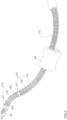
Fig. 1 is an overall structural schematic diagram according to the present invention; -
Fig. 2 is a structural schematic diagram of a distal structural body according to the present invention; -
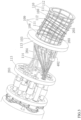
Fig. 3 is a structural schematic diagram of a proximal structural body and a middle connecting body according to the present invention; -
Fig. 4 is a structural schematic diagram of a driving unit using a first type of linear motion mechanism according to the present invention; -
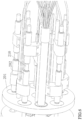
Fig. 5 is a structural schematic diagram of the driving unit inFig. 4 viewed from another view angle; -
Fig. 6 is a structural schematic diagram of a driving unit using a second type of linear motion mechanism according to the present invention; -
Fig. 7 is a structural schematic diagram of the driving unit inFig. 6 viewed from another view angle; -
Fig. 8 is a structural schematic diagram of a surgical end effector driving mechanism according to the present invention; -
Fig. 9 is a structural schematic diagram according to the present invention with a shell, a sterile barrier, a motor assembly and a linear module being installed; -
Fig. 10 is a schematic diagram according to the present invention with a sterile barrier being connected to a shell; and -
Fig. 11 is a structural schematic diagram of the distal structural body using a flexible sheath according to the present invention. - The present invention is described in detail below in conjunction with the accompanying drawings and embodiments.
- As shown in
Fig. 1 , the present invention comprises a flexiblecontinuous body structure 10 and adriving unit 20. - The flexible
continuous body structure 10 of the present invention comprises a distal structural body 101 (as shown inFig. 2 ), a proximalstructural body 102 and amiddle connecting body 103, wherein the distalstructural body 101 is linked to the proximalstructural body 102 by means of the middle connectingbody 103; and thedriving unit 20 is linked to the proximalstructural body 102, and when thedriving unit 20 drives the proximalstructural body 102 to turn in any direction, the distalstructural body 101 correspondingly turns in the opposite direction. As shown inFig. 2 , the distalstructural body 101 comprises two distalstructural segments structural segments distal spacing disks 106, adistal fixing disk 107 andstructural backbones 108. Thedistal spacing disks 106 are uniformly distributed in the distalstructural body 101 at intervals, and have a function to prevent thestructural backbones 108 from becoming unstable when being pushed. As shown inFig. 3 , the proximalstructural body 102 comprises two proximalstructural segments structural segments proximal spacing disks 111, a proximalfixing disk 112 andstructural backbones 108. Theproximal spacing disks 111 are uniformly distributed in the proximalstructural body 102 at intervals, and have a function to prevent thestructural backbones 108 from becoming unstable when being pushed. Thestructural backbones 108 on the first proximalstructural segment 109 are securely connected, in one-to-one correspondence, to or are the same as thestructural backbones 108 on the first distalstructural segment 104, and thestructural backbones 108 on the second proximalstructural segment 110 are securely connected, in one-to-one correspondence, to or are the same as thestructural backbones 108 on the second distalstructural segment 105; and for each of the distalstructural segments structural segments structural backbones 108 is three or more. The number of the distal structural segments comprised in the distalstructural body 101 and the number of the proximal structural segments comprised in the proximalstructural body 102 may also be one or more than two, but the number of the proximal structural segments is always consistent with the number of the distal structural segments. Themiddle connecting body 103 comprises twochannel fixing plates 113 and a structuralbackbone guide channel 114 provided between thechannel fixing plates 113. One end of each of thestructural backbones 108 on the first proximalstructural segment 109 is securely connected to theproximal fixing disk 112 on the first proximalstructural segment 109 and passes through theproximal spacing disks 111 on the first proximalstructural segment 109, the structuralbackbone guide channel 114, and thedistal spacing disks 106 on the first distalstructural segment 104 in sequence, and the other end of the structural backbone is securely connected to thedistal fixing disk 107 on the first distalstructural segment 104. One end of each of thestructural backbones 108 on the second proximalstructural segment 110 is securely connected to theproximal fixing disk 112 on the second proximalstructural segment 110 and passes through theproximal spacing disks 111 on the second proximalstructural segment 110, theproximal fixing disk 112 on the first proximalstructural segment 109, theproximal spacing disks 111 on the first proximalstructural segment 109, the structuralbackbone guide channel 114, thedistal spacing disks 106 on the first distalstructural segment 104, thefixing disk 107 on the first distalstructural segment 104, and thedistal spacing disks 106 on the second distalstructural segment 105 in sequence, and the other end of the structural backbone is securely connected to thedistal fixing disk 107 on the second distalstructural segment 105. The structuralbackbone guide channel 114 has a function to keep the shape of thestructural backbones 108 unchanged under a pushing or pulling force, and the structural backbone guide channel may be of the sleeve structure as shown inFig. 3 , or may be in any other structural form, such as a multi-cavity structure, capable of maintaining the shape of thestructural backbones 108 unchanged under a pushing or pulling force. - The
structural backbones 108 on the first distalstructural segment 104, thestructural backbones 108 on the second distalstructural segment 105, thestructural backbones 108 on the first proximalstructural segment 109, and thestructural backbones 108 of the second proximalstructural segment 110 are elastic elongated rods or elastic elongated tubes. When thestructural backbones 108 on the first distalstructural segment 104 and thestructural backbones 108 on the first proximalstructural segment 109 are elastic elongated tubes, thestructural backbones 108 on the second distalstructural segment 105 may also pass through thestructural backbones 108 on the first distalstructural segment 104, and accordingly thestructural backbones 108 on the second proximalstructural segment 110 may also pass through the interior of thestructural backbones 108 of the first proximalstructural segment 109. - As shown in
Fig. 4 , the drivingunit 20 comprises a drivingunit fixing plate 201 arranged in front of themiddle connecting body 103, a plurality oflinear motion mechanisms 202 for converting a rotary motion input into a linear motion output are provided between the drivingunit fixing plate 201 and thechannel fixing plate 113, an output end of thelinear motion mechanism 202 is securely connected to one end of a drivingbackbone 203, and a drivingbackbone guide channel 204 is further provided between the twochannel fixing plates 113; and the drivingbackbone 203 passes through the drivingbackbone guide channel 204 and theproximal spacing disks 111 in sequence, and the other end of the driving backbone is securely connected to theproximal fixing disk 112. The drivingbackbone guide channel 204 has a function to keep the shape of the drivingbackbone 203 unchanged under a pushing or pulling force, and the driving backbone guide channel may be of the sleeve structure as shown inFig. 3 , or may be in any other structural form, such as a multi-cavity structure, capable of maintaining the shape of the drivingbackbone 203 unchanged under a pushing or pulling force. In this embodiment, eight drivingbackbones 203 are provided, four of which are securely connected to theproximal fixing disk 112 on the first proximalstructural segment 109, and the other four are securely connected to theproximal fixing disk 112 on the second proximalstructural segment 110. By means of the cooperative pushing or pulling, by the drivingunit 20, of the drivingbackbones 203 connected to the first proximalstructural segment 109, the first proximalstructural segment 109 can turn at a degree of freedom in any direction, and when the first proximalstructural segment 109 turns in a certain direction, the first distalstructural segment 104 will turn in the opposite direction in a certain proportional relationship (determined jointly by the distribution radii of thestructural backbones 108 in the first proximalstructural segment 109 and in the first distal structural segment 104). Similarly, by means of the cooperative pushing or pulling, by the drivingunit 20, of the drivingbackbones 203 connected to the second proximalstructural segment 110, the second proximalstructural segment 110 can turn at a degree of freedom in any direction, and when the second proximalstructural segment 110 turns in a certain direction, the second distalstructural segment 105 will turn in the opposite direction in a certain proportional relationship (determined jointly by the distribution radii of thestructural backbones 108 of the second proximalstructural segment 110 and the second distal structural segment 105). For each of the proximalstructural segments backbones 203 is three or more. - In the above embodiment, as shown in
Figs. 4 and5 , thelinear motion mechanism 202 comprises a threadedrod 205 rotatably arranged between the drivingunit fixing plate 201 and thechannel fixing plate 113, ashaft 206a securely arranged between the drivingunit fixing plate 201 and thechannel fixing plate 113, and aslider 207a slidably connected to theshaft 206a and threadedly fitted with the threadedrod 205, and theslider 207a serves as a motion end of thelinear motion mechanism 202 and is securely connected to the drivingbackbone 203. The threadedrods 205 pass through the drivingunit fixing plate 201, agear 208 is securely connected to the threadedrod 205 at a front side of the drivingunit fixing plate 201, every two of the threadedrods 205 are one group, twogears 208 located on one group of threadedrods 205 mesh with each other, and twosliders 207a on one group of the threadedrods 205 are securely connected to a pair of drivingbackbones 203, so as to cooperatively push or pull the pair of drivingbackbones 203 to implement turning of a certain structural segment in the proximalstructural body 102. Amale coupling 209 is securely connected to a front end of one of the threadedrods 205 in each group of the threadedrods 205. In this embodiment, four groups of, i.e., eight threadedrods 205 are provided for driving the eightdriving backbones 203 to perform cooperative pushing or pulling, and accordingly fourmale couplings 209 are provided. - As shown in
Figs. 6 and7 , thelinear motion mechanism 202 may also be of another structure, comprising a double-head threadedrod 210 rotatably arranged between the drivingunit fixing plate 201 and thechannel fixing plate 113 and ashaft 206b securely arranged between the drivingunit fixing plate 201 and thechannel fixing plate 113, two threaded sections of the double-head threadedrod 210 are respectively connected to one of thesliders 207b by a threaded fit, and each of thesliders 207b is slidably connected to one of theshafts 206b. A pair of the drivingbackbones 203 are respectively securely connected to the twosliders 207b located on the same double-head threadedrod 210. The double-head threadedrod 210 passes through the drivingunit fixing plate 201, and a front end of the double-head threaded rod is securely connected to amale coupling 209. In this embodiment, four double-head threadedrods 210 are provided, and can drive the eightdriving backbones 203 to perform cooperative pushing or pulling, and accordingly fourmale couplings 209 are provided. - In the above embodiment, as shown in
Figs. 1 and5 , the distalstructural body 101 is externally covered with anenvelope 30, a front end of theenvelope 30 is fixedly connected to asurgical end effector 40, a rear end of theenvelope 30 is securely connected to arotary sleeve 301 which is rotatably supported on a front end of the drivingunit fixing plate 201, the front end of the drivingunit fixing plate 201 is further provided with arotary shaft 302, a pair ofgears 303 meshing with each other are securely arranged on therotary shaft 302 and therotary sleeve 301, and a front end of therotary shaft 302 is securely connected to amale coupling 304. By means of driving therotary shaft 302 to rotate, therotary sleeve 301 and theenvelope 30 can be driven to rotate so as to drive thesurgical end effector 40 to rotate, thereby implementing the directional adjustment of thesurgical end effector 40 around its own axis. - In the above embodiment, as shown in
Figs. 2 ,3 and8 , anactuation wire 401 of thesurgical end effector 40 passes through the distalstructural body 101, the other end of the actuation wire is connected to a surgical endeffector driving mechanism 402 located on thechannel fixing plate 113, and the surgical endeffector driving mechanism 402 controls the surgical end effector 40 (such as surgical forceps) by physically pushing or pulling theactuation wire 401. Theactuation wire 401 may also transfer various forms of energy, such as electrical energy and high-frequency vibrations, to achieve specific surgical functions of thesurgical end effector 40. The above surgical endeffector driving mechanism 402 comprises a base 403 securely connected to thechannel fixing plate 113, a connectingrod 404 is rotatably arranged on thebase 403, afirst slider 405 is connected to one end of the connectingrod 404, thefirst slider 405 is slidably connected to afirst shaft 406 arranged on thebase 403, and theactuation wire 401 is securely connected to thefirst slider 405; and asecond slider 407 is connected to the other end of the connectingrod 404, and thesecond slider 407 is slidably connected to asecond shaft 408 arranged on thechannel fixing plate 113. A driving threadedrod 409 is rotatably supported on the drivingunit fixing plate 201, a front end of the driving threadedrod 409 is provided with a male coupling 410 (as shown inFig. 5 ), a third slider (not shown in the figure) is connected to the driving threadedrod 409 by a threaded fit, the third slider is slidably connected to a third shaft (not shown in the figure) located between the drivingunit fixing plate 201 and thechannel fixing plate 113, and the third slider is securely connected to thesecond slider 407 by means of a drivingrod 412. When the driving threadedrod 409 turns, the third slider will move in a linear motion along the third shaft, while the third slider drives, by means of the drivingrod 412 securely connected thereto, thesecond slider 407 to move in a linear motion along thesecond shaft 408 so as to drive, by means of the connectingrod 404, thefirst slider 405 to move in a linear motion along thefirst shaft 406 so as to physically push or pull theactuation wire 401. Further, a actuationwire guide sleeve 411 is provided between the base 403 and thechannel fixing plate 113, and is used to keep the shape of theactuation wire 401 unchanged under a pushing or pulling force. - In the above embodiment, as shown in
Fig. 9 , the present invention further comprises ashell 50; and the drivingunit fixing plate 201 and thechannel fixing plates 113 are all fixedly connected to theshell 50; the proximalstructural body 102, themiddle connecting body 103 and the drivingunit 20 are all located inside theshell 50. A front end of theshell 50 is connected to amotor assembly 70 by means of asterile barrier 60, as shown inFig. 10 , and thesterile barrier 60 comprises acover 601 and afemale coupling 602 arranged on thecover 601, wherein thecover 601 is respectively connected to theshell 50 and a housing of themotor assembly 70 by means of a fast connection structure, such that themotor assembly 70, thesterile barrier 60 and theshell 50 are detachably connected with each other; and a rear end of thefemale coupling 602 is connected to themale couplings female coupling 602 is connected to a motor output shaft in themotor assembly 70 by means of another male coupling (not shown in the figure). A sterile membrane (not shown in the figure) is connected to the periphery of thesterile barrier 60, and is used for separating theunsterilized motor assembly 70 from other sterilized parts, ensuring the clinical practicability of the flexible surgical instrument system. - In the above embodiment, as shown in
Fig. 9 , the present invention further comprises a linear module 80 (thelinear module 80 also being separated from the sterilized parts by means of the sterile membrane) which comprises asupport 801 with a sliding groove, wherein alead screw 802 is rotatably arranged on thesupport 801, thelead screw 802 is sheathed with aslider 803 which is threadedly fitted with thelead screw 802 and slidably arranged in the sliding groove, one end of thesupport 801 is provided with amotor 804, and an output shaft of themotor 804 is securely connected to thelead screw 802 by means of a coupling. The housing of themotor assembly 70 is securely connected to theslider 803. When the output shaft of themotor 804 turns, theslider 803 will drive themotor assembly 70, thesterile barrier 60 and theshell 50 to move in a linear motion along the sliding groove, such that the flexiblecontinuous body structure 10 performs a feed motion. - In the above embodiment, as shown in
Fig. 2 , in an application, asheath 90 is fixed at a single incision in the abdominal cavity, and the distalstructural body 101, together with theenvelope 30 and thesurgical end effector 40, can freely pass through a through-hole in thesheath 90 for the passage of the surgical instrument and have access to the surgical site. As shown inFig. 11 , thesheath 90 may also be a flexible sheath that can more easily extend into various natural orifices of the human body and adaptively change shape as the shape of the orifices, one end of the flexible sheath is fixed at the entrance of the orifice, and the distalstructural body 101, together with theenvelope 30 and thesurgical end effector 40, can also freely pass through a through-hole in the flexible sheath for the passage of the surgical instrument and have access to the surgical site. - The present invention has been illustrated only by the above embodiment, and the structure, arrangement position and connection of the components can be varied. On the basis of the technical solutions of the present invention, the improvements or equivalent changes to individual components according to the principles of the present invention should not be excluded from the scope of protection of the present invention.
Claims (12)
- A flexible surgical instrument system with a front drive input, comprising a flexible continuous body structure (10) and a driving unit (20), wherein the flexible continuous body structure (10) comprises a distal structural body (101), a proximal structural body (102) and a middle connecting body (103); the distal structural body (101) comprises at least one distal structural segment (104,105), and the distal structural segment (104,105) comprises distal spacing disks (106), a distal fixing disk (107) and structural backbones (108); the proximal structural body (102) comprises a proximal structural segment (109,110), and the proximal structural segment (109,110) comprises proximal spacing disks (111), a proximal fixing disk (112) and structural backbones (108); the middle connecting body (103) comprises two channel fixing plates (113) and a structural backbone guide channel (114) provided between the two channel fixing plates (113) ; the structural backbones (108) of the distal structural segment (104,105) are securely connected, in one-to-one correspondence, to or are the same as the structural backbones (108) of the proximal structural segment (109,110), one end of each of the structural backbones (108) is securely connected to the proximal fixing disk (112), passing through the proximal spacing disks (111), the structural backbone guide channel (114) and the distal spacing disks (106) in sequence, the other end of the structural backbone is securely connected to the distal fixing disk (107); andthe driving unit (20) comprises a driving unit fixing plate (201) arranged in front of the middle connecting body (103), a plurality of linear motion mechanisms (202) for converting a rotary motion input into a linear motion output are provided between the driving unit fixing plate (201) and the channel fixing plate (113), output ends of the linear motion mechanisms (202) are connected to one end of a driving backbone (203), the driving backbone (203) passes through the proximal spacing disks (111), and the other end of the driving backbone (203) is securely connected to the proximal fixing disk (112);characterized in that,the distal structural body (101) is externally covered with an envelope (30), a front end of the envelope (30) is securely connected to a surgical end effector (40), and a rear end of the envelope (30) is connected to a rotary driving mechanism in the driving unit (20);the rotary driving mechanism comprises a rotary sleeve (301) rotatably supported at a front side of the driving unit fixing plate (201), and a front end of the rotary sleeve (301) is securely connected to the envelope (30); and the front side of the driving unit fixing plate (201) is further provided with a rotary shaft (302), a pair of gears (303) meshing with each other are provided on the rotary shaft (302) and the rotary sleeve (301) , and a male coupling (304) directly or indirectly connected to an output shaft of a motor is securely connected to a front end of the rotary shaft (302).
- A flexible surgical instrument system with a front drive input of claim 1, wherein the linear motion mechanism (202) comprises a threaded rod (205) rotatably arranged between the driving unit fixing plate (201) and the channel fixing plate (113), a shaft (206a) securely arranged between the driving unit fixing plate (201) and the channel fixing plate (113), and a slider (207a) slidably connected to the shaft (206a) and threadedly fitted with the threaded rod (205); and the driving backbone (203) is securely connected to the slider (207a).
- A flexible surgical instrument system with a front drive input of claim 2, wherein the threaded rods (205) pass through the driving unit fixing plate (201), a gear (208) is securely connected to the threaded rod (205) at a front side of the driving unit fixing plate (201), every two of the threaded rods (205) being a group; a pair of the driving backbones (203) are securely connected to the slider (207a) on one group of the threaded rods (205); and the gears (208) on one group of the threaded rods (205) mesh with each other, and a male coupling (209) directly or indirectly connected to an output shaft of a motor is securely connected to a front end of one of the threaded rods (205) in one group of the threaded rods (205).
- A flexible surgical instrument system with a front drive input of claim 1, wherein the linear motion mechanism (202) comprises double-head threaded rods (210) rotatably arranged between the driving unit fixing plate (201) and the channel fixing plate (113), and shafts securely arranged between the driving unit fixing plate (201) and the channel fixing plate (113), and two threaded sections of the double-head threaded rod (210) are respectively connected to a slider (207b) by a threaded fit, each of the sliders (207b) being slidably connected to one of the shafts (206b) ; a pair of the driving backbones (203) are respectively securely connected to the two sliders (207b) located on the same double-head threaded rod (210) ; and the double-head threaded rod (210) passes through the driving unit fixing plate (201), and a front end of the double-head threaded rod (210) is securely connected to a male coupling (209) directly or indirectly connected to an output shaft of a motor.
- A flexible surgical instrument system with a front drive input of claim 1, wherein a driving backbone guide channel (204) is provided between the two channel fixing plates (113) , and the driving backbone (203) passes through the driving backbone guide channel (204) .
- A flexible surgical instrument system with a front drive input of claim 1, whereinwhen the distal structural body (101) comprises two distal structural segments (104,105), the structural backbones (108) on the distal structural segment (105) away from the middle connecting body (103) pass through the distal fixing disk (107) and the distal spacing disks (106) on the distal structural segment (104) near the middle connecting body (103), orwhen the distal structural body (101) comprises two distal structural segments (104,105),and the structural backbones (108) on the distal structural segment (104) near the middle connecting body (103) are elastic elongated tubes, the structural backbones (108) on the distal structural segment (105) away from the middle connecting body (103) pass through the interior of the structural backbones (108) on the distal structural segment (104) near the middle connecting body (103); andwhen the proximal structural body (102) comprises two proximal structural segments (109,110), the structural backbones (108) on the proximal structural segment (110) away from the middle connecting body (103) pass through the proximal fixing disk (112) and the proximal spacing disks (111) on the proximal structural segment (109) near the middle connecting body (103), orwhen the proximal structural body (102) comprises two proximal structural segments (109,110), and the structural backbones (108) on the proximal structural segment (109) near the middle connecting body (103) are elastic elongated tubes, the structural backbones (108) on the proximal structural segment (110) away from the middle connecting body (103) pass through the interior of the structural backbones (108) on the proximal structural segment near the middle connecting body (103).
- A flexible surgical instrument system with a front drive input of claim 1, wherein a front end of the distal structural body (101) is provided with a surgical end effector (40), an actuation wire (401) of the surgical end effector (40) passes through the distal structural body (101), and the other end of the actuation wire (401) is connected to a surgical end effector driving mechanism (402) which is located on the channel fixing plate (113) and is used for converting a rotary motion input into a linear motion output.
- A flexible surgical instrument system with a front drive input of claim 7, wherein the surgical end effector driving mechanism (402) comprises a base (403) securely connected to the channel fixing plate (113), a connecting rod is rotatably connected to the base (403), one end of the connecting rod is connected to a first slider (405), the first slider (405) is slidably connected to a first shaft (406) arranged on the base (403), and the actuation wire (401) of the surgical end effector (40) is securely connected to the first slider (405); the other end of the connecting rod (404) is connected to a second slider (407), and the second slider (407) is slidably connected to a second shaft (408) arranged on the channel fixing plate (113); and a driving threaded rod (409) is rotatably supported on the driving unit fixing plate (201), a front end of the driving threaded rod (409) is provided with a male coupling (410) directly or indirectly connected to an output shaft of a motor, a third slider is connected to the driving threaded rod (409) by a threaded fit, the third slider is slidably connected to a third shaft arranged between the driving unit fixing plate (201) and the channel fixing plate (113), and the third slider is connected to the second slider (407) by means of a driving rod (412).
- A flexible surgical instrument system with a front drive input of claim 1, further comprising a shell (50), a sterile barrier (60), a motor assembly (70) and a linear module (80), wherein the driving unit fixing plate (201) and the channel fixing plates (113) are all securely connected to the shell (50), and the proximal structural body (102), the middle connecting body (103) and the driving unit (20) are all located inside the shell (50); a front end of the shell (50) is connected to the motor assembly (70) by means of the sterile barrier (60); and the linear module (80) comprises a support (801), a motor (804) securely connected to the support (801), and a linear feed mechanism securely connected to an output shaft of the motor, an output end of the linear feed mechanism is securely connected to a housing of the motor assembly (70), and the motor drives the motor assembly (70) by means of the linear feed mechanism to drive the flexible continuous body structure (10) and the driving unit (20) to perform a linear motion by means of the sterile barrier (60).
- A flexible surgical instrument system with a front drive input of claim 9, wherein the linear feed mechanism comprises a lead screw (802) rotatably connected to the support (801), the lead screw (802) is sheathed with a slider which is threadedly fitted with the lead screw (802), a linear sliding groove is provided on the support (801), and the slider is slidably arranged in the linear sliding groove; and an output shaft of the motor is securely connected to the lead screw by means of a coupling.
- A flexible surgical instrument system with a front drive input of claim 3 or 4, further comprising a shell( 50), wherein the driving unit fixing plate (201) and the channel fixing plates (113) are both securely connected to the shell (50), the proximal structural body (102), the middle connecting body (103) and the driving unit (20) are all located inside the shell (50), a front end of the shell (50) is connected to a motor assembly (70) by means of a sterile barrier (60), the sterile barrier (60) comprises a cover (601) and a female coupling (602) rotatably arranged on the cover (601), a rear end of the female coupling (602) is connected to the male coupling (209,304,410), a front end of the female coupling (602) is connected to a motor output shaft of the motor assembly (70) by means of another male coupling, and the periphery of the cover (601) is connected to a sterile membrane.
- A flexible surgical instrument system with a front drive input of any one of claims 1-10, wherein the number of the proximal structural segments (109,110) is equal to the number of the distal structural segments (104,105).
Applications Claiming Priority (3)
| Application Number | Priority Date | Filing Date | Title |
|---|---|---|---|
| CN201610798138.XA CN106420059B (en) | 2016-08-31 | 2016-08-31 | A flexible surgical tool system with front drive input |
| CN201610796071.6A CN106308935B (en) | 2016-08-31 | 2016-08-31 | A kind of flexible operation tool system using double threaded screw driving |
| PCT/CN2017/099754 WO2018041158A1 (en) | 2016-08-31 | 2017-08-30 | Flexible surgical instrument system with prepositioned drive input |
Publications (3)
| Publication Number | Publication Date |
|---|---|
| EP3508159A1 EP3508159A1 (en) | 2019-07-10 |
| EP3508159A4 EP3508159A4 (en) | 2020-04-08 |
| EP3508159B1 true EP3508159B1 (en) | 2023-03-08 |
Family
ID=61301419
Family Applications (1)
| Application Number | Title | Priority Date | Filing Date |
|---|---|---|---|
| EP17845460.9A Active EP3508159B1 (en) | 2016-08-31 | 2017-08-30 | Flexible surgical instrument system with prepositioned drive input |
Country Status (3)
| Country | Link |
|---|---|
| US (1) | US11903571B2 (en) |
| EP (1) | EP3508159B1 (en) |
| WO (1) | WO2018041158A1 (en) |
Families Citing this family (5)
| Publication number | Priority date | Publication date | Assignee | Title |
|---|---|---|---|---|
| CN112971987A (en) * | 2019-12-18 | 2021-06-18 | 新加坡国立大学 | Variable rigidity and flexible robot control device |
| US12213681B2 (en) * | 2020-05-06 | 2025-02-04 | Atricure, Inc. | End effector positioning mechanism |
| CN114098846B (en) * | 2020-08-28 | 2024-10-11 | 中国科学院沈阳自动化研究所 | Surgical instrument driving module |
| JP2023086218A (en) * | 2021-12-10 | 2023-06-22 | キヤノン株式会社 | SUPPORT DEVICE AND METHOD OF MANUFACTURING THE SUPPORT DEVICE |
| WO2025191426A1 (en) * | 2024-03-14 | 2025-09-18 | Covidien Lp | Drive mechanisms for surgical instruments such as for use in robotic surgical systems |
Citations (4)
| Publication number | Priority date | Publication date | Assignee | Title |
|---|---|---|---|---|
| US20060199999A1 (en) * | 2001-06-29 | 2006-09-07 | Intuitive Surgical Inc. | Cardiac tissue ablation instrument with flexible wrist |
| EP2594211A1 (en) * | 2011-11-16 | 2013-05-22 | Covidien LP | Surgical device with powered articulation |
| WO2015100000A2 (en) * | 2013-12-23 | 2015-07-02 | Ethicon Endo-Surgery, Inc. | Surgical cutting and stapling instruments with articulatable end effectors |
| US20150265355A1 (en) * | 2014-03-18 | 2015-09-24 | Richard Wolf Gmbh | Endoscopic instrument for the connection to an operation robot |
Family Cites Families (18)
| Publication number | Priority date | Publication date | Assignee | Title |
|---|---|---|---|---|
| CA2406522C (en) | 2000-04-21 | 2009-07-14 | Universite Pierre Et Marie Curie (Paris Vi) | Device for positioning, exploring and/or operating in particular in the field of endoscopy and/or minimally invasive surgery |
| US20130090763A1 (en) | 2008-01-25 | 2013-04-11 | The Trustees Of Columibia University In The City Of The City Of New York | Systems and methods for force sensing in a robot |
| CN101653353B (en) | 2009-08-28 | 2010-12-01 | 哈尔滨工业大学 | Continuum semi-autonomous endoscopic robot |
| IT1399603B1 (en) | 2010-04-26 | 2013-04-26 | Scuola Superiore Di Studi Universitari E Di Perfez | ROBOTIC SYSTEM FOR MINIMUM INVASIVE SURGERY INTERVENTIONS |
| US10737398B2 (en) | 2010-07-08 | 2020-08-11 | Vanderbilt University | Continuum devices and control methods thereof |
| US20130338433A1 (en) * | 2010-07-27 | 2013-12-19 | Roger Goldman | Rapidly deployable flexible robotic instrumentation |
| WO2013158978A1 (en) * | 2012-04-20 | 2013-10-24 | Vanderbilt University | Method and system for compliant insertion of continuum robots |
| CN103085083B (en) | 2013-01-07 | 2015-06-24 | 汪雯 | Flexible continuous body mechanical structure capable of bending and stretching |
| US9408669B2 (en) * | 2013-03-15 | 2016-08-09 | Hansen Medical, Inc. | Active drive mechanism with finite range of motion |
| CN103340731B (en) | 2013-07-10 | 2015-04-08 | 上海交通大学 | Exoskeleton auxiliary rehabilitation therapy system based on fluid transformation |
| CN103315781B (en) | 2013-07-10 | 2015-03-18 | 上海交通大学 | Endoscope noninvasive surgery system |
| CN103340707B (en) | 2013-07-10 | 2015-03-11 | 上海交通大学 | External skeleton assisted rehabilitation therapy system |
| JP6081309B2 (en) * | 2013-07-24 | 2017-02-15 | オリンパス株式会社 | Medical manipulator |
| CN103707322B (en) * | 2013-12-31 | 2016-04-20 | 汪雯 | Retractable and flexible non-individual body frame for movement can be curved |
| CN103948435B (en) * | 2014-05-15 | 2016-04-13 | 上海交通大学 | Single-port laparoscopic minimally-invasive surgery robot system |
| CN105856213B (en) * | 2016-04-13 | 2017-10-10 | 上海交通大学 | A kind of modularization highly redundant multiple degrees of freedom flexible mechanical arm system |
| CN106420059B (en) * | 2016-08-31 | 2019-03-15 | 北京术锐技术有限公司 | A flexible surgical tool system with front drive input |
| CN106308935B (en) | 2016-08-31 | 2018-12-07 | 北京术锐技术有限公司 | A kind of flexible operation tool system using double threaded screw driving |
-
2017
- 2017-08-30 WO PCT/CN2017/099754 patent/WO2018041158A1/en not_active Ceased
- 2017-08-30 US US16/329,723 patent/US11903571B2/en active Active
- 2017-08-30 EP EP17845460.9A patent/EP3508159B1/en active Active
Patent Citations (4)
| Publication number | Priority date | Publication date | Assignee | Title |
|---|---|---|---|---|
| US20060199999A1 (en) * | 2001-06-29 | 2006-09-07 | Intuitive Surgical Inc. | Cardiac tissue ablation instrument with flexible wrist |
| EP2594211A1 (en) * | 2011-11-16 | 2013-05-22 | Covidien LP | Surgical device with powered articulation |
| WO2015100000A2 (en) * | 2013-12-23 | 2015-07-02 | Ethicon Endo-Surgery, Inc. | Surgical cutting and stapling instruments with articulatable end effectors |
| US20150265355A1 (en) * | 2014-03-18 | 2015-09-24 | Richard Wolf Gmbh | Endoscopic instrument for the connection to an operation robot |
Also Published As
| Publication number | Publication date |
|---|---|
| WO2018041158A1 (en) | 2018-03-08 |
| EP3508159A4 (en) | 2020-04-08 |
| US11903571B2 (en) | 2024-02-20 |
| EP3508159A1 (en) | 2019-07-10 |
| US20190231329A1 (en) | 2019-08-01 |
Similar Documents
| Publication | Publication Date | Title |
|---|---|---|
| US12193777B2 (en) | Flexible surgical instrument system based on continuous body structure | |
| US11234685B2 (en) | Flexible surgical instrument system | |
| US11872002B2 (en) | Flexible surgical instrument system | |
| CN111437036B (en) | Serpentine surgical robot applied to minimally invasive surgery | |
| EP3903715B1 (en) | Flexible surgical tool system | |
| US11844503B2 (en) | Flexible surgical instrument system | |
| EP3508161B1 (en) | Flexible surgical instrument system | |
| EP3508154B1 (en) | Flexible surgical instrument system | |
| EP3508162B1 (en) | Flexible surgical instrument system | |
| EP3903711A1 (en) | Double-curved flexible surgical tool system | |
| EP4221605B1 (en) | Medical devices having compact end effector drive mechanisms with high grip force | |
| US11903571B2 (en) | Flexible surgical instrument system with prepositioned drive input | |
| CN117357261A (en) | Variable-rigidity single-hole flexible surgical robot | |
| CN106308935A (en) | Flexible surgical operation tool system driven by twin thread screw | |
| CN106236272A (en) | A kind of flexible operation tool system using restraining structure bone | |
| CN106420059A (en) | Flexible operation tooling system with preposed driving input | |
| EP3508152B1 (en) | Sterilizable flexible surgical instrument system | |
| WO2021173315A1 (en) | Robotic surgical instrument including linear encoders for measuring cable displacement | |
| CN206443718U (en) | Can transurethral hand instrument |
Legal Events
| Date | Code | Title | Description |
|---|---|---|---|
| STAA | Information on the status of an ep patent application or granted ep patent |
Free format text: STATUS: THE INTERNATIONAL PUBLICATION HAS BEEN MADE |
|
| PUAI | Public reference made under article 153(3) epc to a published international application that has entered the european phase |
Free format text: ORIGINAL CODE: 0009012 |
|
| STAA | Information on the status of an ep patent application or granted ep patent |
Free format text: STATUS: REQUEST FOR EXAMINATION WAS MADE |
|
| 17P | Request for examination filed |
Effective date: 20190329 |
|
| AK | Designated contracting states |
Kind code of ref document: A1 Designated state(s): AL AT BE BG CH CY CZ DE DK EE ES FI FR GB GR HR HU IE IS IT LI LT LU LV MC MK MT NL NO PL PT RO RS SE SI SK SM TR |
|
| AX | Request for extension of the european patent |
Extension state: BA ME |
|
| DAV | Request for validation of the european patent (deleted) | ||
| DAX | Request for extension of the european patent (deleted) | ||
| A4 | Supplementary search report drawn up and despatched |
Effective date: 20200311 |
|
| RIC1 | Information provided on ipc code assigned before grant |
Ipc: A61B 17/00 20060101ALI20200305BHEP Ipc: A61B 34/30 20160101AFI20200305BHEP Ipc: A61B 34/00 20160101ALI20200305BHEP |
|
| RAP1 | Party data changed (applicant data changed or rights of an application transferred) |
Owner name: BEIJING SURGERII TECHNOLOGY CO., LTD. |
|
| RIN1 | Information on inventor provided before grant (corrected) |
Inventor name: YANG, ZHIXIONG Inventor name: DAI, ZHENGCHEN Inventor name: XU, KAI Inventor name: ZHANG, SHU'AN Inventor name: LIU, HUAN Inventor name: ZHU, ZHIJUN Inventor name: ZHAO, JIANGRAN Inventor name: CHEN, YUYANG |
|
| GRAP | Despatch of communication of intention to grant a patent |
Free format text: ORIGINAL CODE: EPIDOSNIGR1 |
|
| STAA | Information on the status of an ep patent application or granted ep patent |
Free format text: STATUS: GRANT OF PATENT IS INTENDED |
|
| INTG | Intention to grant announced |
Effective date: 20221026 |
|
| RIN1 | Information on inventor provided before grant (corrected) |
Inventor name: ZHU, ZHIJUN Inventor name: YANG, ZHIXIONG Inventor name: CHEN, YUYANG Inventor name: LIU, HUAN Inventor name: ZHAO, JIANGRAN Inventor name: DAI, ZHENGCHEN Inventor name: ZHANG, SHU'AN Inventor name: XU, KAI |
|
| GRAS | Grant fee paid |
Free format text: ORIGINAL CODE: EPIDOSNIGR3 |
|
| GRAA | (expected) grant |
Free format text: ORIGINAL CODE: 0009210 |
|
| STAA | Information on the status of an ep patent application or granted ep patent |
Free format text: STATUS: THE PATENT HAS BEEN GRANTED |
|
| AK | Designated contracting states |
Kind code of ref document: B1 Designated state(s): AL AT BE BG CH CY CZ DE DK EE ES FI FR GB GR HR HU IE IS IT LI LT LU LV MC MK MT NL NO PL PT RO RS SE SI SK SM TR |
|
| REG | Reference to a national code |
Ref country code: GB Ref legal event code: FG4D |
|
| REG | Reference to a national code |
Ref country code: CH Ref legal event code: EP Ref country code: AT Ref legal event code: REF Ref document number: 1552062 Country of ref document: AT Kind code of ref document: T Effective date: 20230315 |
|
| REG | Reference to a national code |
Ref country code: DE Ref legal event code: R096 Ref document number: 602017066700 Country of ref document: DE |
|
| REG | Reference to a national code |
Ref country code: IE Ref legal event code: FG4D |
|
| RAP4 | Party data changed (patent owner data changed or rights of a patent transferred) |
Owner name: BEIJING SURGERII ROBOTICS COMPANY LIMITED |
|
| REG | Reference to a national code |
Ref country code: LT Ref legal event code: MG9D |
|
| REG | Reference to a national code |
Ref country code: NL Ref legal event code: MP Effective date: 20230308 |
|
| PG25 | Lapsed in a contracting state [announced via postgrant information from national office to epo] |
Ref country code: RS Free format text: LAPSE BECAUSE OF FAILURE TO SUBMIT A TRANSLATION OF THE DESCRIPTION OR TO PAY THE FEE WITHIN THE PRESCRIBED TIME-LIMIT Effective date: 20230308 Ref country code: NO Free format text: LAPSE BECAUSE OF FAILURE TO SUBMIT A TRANSLATION OF THE DESCRIPTION OR TO PAY THE FEE WITHIN THE PRESCRIBED TIME-LIMIT Effective date: 20230608 Ref country code: LV Free format text: LAPSE BECAUSE OF FAILURE TO SUBMIT A TRANSLATION OF THE DESCRIPTION OR TO PAY THE FEE WITHIN THE PRESCRIBED TIME-LIMIT Effective date: 20230308 Ref country code: LT Free format text: LAPSE BECAUSE OF FAILURE TO SUBMIT A TRANSLATION OF THE DESCRIPTION OR TO PAY THE FEE WITHIN THE PRESCRIBED TIME-LIMIT Effective date: 20230308 Ref country code: HR Free format text: LAPSE BECAUSE OF FAILURE TO SUBMIT A TRANSLATION OF THE DESCRIPTION OR TO PAY THE FEE WITHIN THE PRESCRIBED TIME-LIMIT Effective date: 20230308 Ref country code: ES Free format text: LAPSE BECAUSE OF FAILURE TO SUBMIT A TRANSLATION OF THE DESCRIPTION OR TO PAY THE FEE WITHIN THE PRESCRIBED TIME-LIMIT Effective date: 20230308 |
|
| REG | Reference to a national code |
Ref country code: AT Ref legal event code: MK05 Ref document number: 1552062 Country of ref document: AT Kind code of ref document: T Effective date: 20230308 |
|
| PG25 | Lapsed in a contracting state [announced via postgrant information from national office to epo] |
Ref country code: SE Free format text: LAPSE BECAUSE OF FAILURE TO SUBMIT A TRANSLATION OF THE DESCRIPTION OR TO PAY THE FEE WITHIN THE PRESCRIBED TIME-LIMIT Effective date: 20230308 Ref country code: NL Free format text: LAPSE BECAUSE OF FAILURE TO SUBMIT A TRANSLATION OF THE DESCRIPTION OR TO PAY THE FEE WITHIN THE PRESCRIBED TIME-LIMIT Effective date: 20230308 Ref country code: GR Free format text: LAPSE BECAUSE OF FAILURE TO SUBMIT A TRANSLATION OF THE DESCRIPTION OR TO PAY THE FEE WITHIN THE PRESCRIBED TIME-LIMIT Effective date: 20230609 Ref country code: FI Free format text: LAPSE BECAUSE OF FAILURE TO SUBMIT A TRANSLATION OF THE DESCRIPTION OR TO PAY THE FEE WITHIN THE PRESCRIBED TIME-LIMIT Effective date: 20230308 |
|
| PG25 | Lapsed in a contracting state [announced via postgrant information from national office to epo] |
Ref country code: SM Free format text: LAPSE BECAUSE OF FAILURE TO SUBMIT A TRANSLATION OF THE DESCRIPTION OR TO PAY THE FEE WITHIN THE PRESCRIBED TIME-LIMIT Effective date: 20230308 Ref country code: RO Free format text: LAPSE BECAUSE OF FAILURE TO SUBMIT A TRANSLATION OF THE DESCRIPTION OR TO PAY THE FEE WITHIN THE PRESCRIBED TIME-LIMIT Effective date: 20230308 Ref country code: PT Free format text: LAPSE BECAUSE OF FAILURE TO SUBMIT A TRANSLATION OF THE DESCRIPTION OR TO PAY THE FEE WITHIN THE PRESCRIBED TIME-LIMIT Effective date: 20230710 Ref country code: EE Free format text: LAPSE BECAUSE OF FAILURE TO SUBMIT A TRANSLATION OF THE DESCRIPTION OR TO PAY THE FEE WITHIN THE PRESCRIBED TIME-LIMIT Effective date: 20230308 Ref country code: CZ Free format text: LAPSE BECAUSE OF FAILURE TO SUBMIT A TRANSLATION OF THE DESCRIPTION OR TO PAY THE FEE WITHIN THE PRESCRIBED TIME-LIMIT Effective date: 20230308 Ref country code: AT Free format text: LAPSE BECAUSE OF FAILURE TO SUBMIT A TRANSLATION OF THE DESCRIPTION OR TO PAY THE FEE WITHIN THE PRESCRIBED TIME-LIMIT Effective date: 20230308 |
|
| PG25 | Lapsed in a contracting state [announced via postgrant information from national office to epo] |
Ref country code: SK Free format text: LAPSE BECAUSE OF FAILURE TO SUBMIT A TRANSLATION OF THE DESCRIPTION OR TO PAY THE FEE WITHIN THE PRESCRIBED TIME-LIMIT Effective date: 20230308 Ref country code: PL Free format text: LAPSE BECAUSE OF FAILURE TO SUBMIT A TRANSLATION OF THE DESCRIPTION OR TO PAY THE FEE WITHIN THE PRESCRIBED TIME-LIMIT Effective date: 20230308 Ref country code: IS Free format text: LAPSE BECAUSE OF FAILURE TO SUBMIT A TRANSLATION OF THE DESCRIPTION OR TO PAY THE FEE WITHIN THE PRESCRIBED TIME-LIMIT Effective date: 20230708 |
|
| REG | Reference to a national code |
Ref country code: DE Ref legal event code: R097 Ref document number: 602017066700 Country of ref document: DE |
|
| PLBE | No opposition filed within time limit |
Free format text: ORIGINAL CODE: 0009261 |
|
| STAA | Information on the status of an ep patent application or granted ep patent |
Free format text: STATUS: NO OPPOSITION FILED WITHIN TIME LIMIT |
|
| PG25 | Lapsed in a contracting state [announced via postgrant information from national office to epo] |
Ref country code: SI Free format text: LAPSE BECAUSE OF FAILURE TO SUBMIT A TRANSLATION OF THE DESCRIPTION OR TO PAY THE FEE WITHIN THE PRESCRIBED TIME-LIMIT Effective date: 20230308 Ref country code: DK Free format text: LAPSE BECAUSE OF FAILURE TO SUBMIT A TRANSLATION OF THE DESCRIPTION OR TO PAY THE FEE WITHIN THE PRESCRIBED TIME-LIMIT Effective date: 20230308 |
|
| 26N | No opposition filed |
Effective date: 20231211 |
|
| PG25 | Lapsed in a contracting state [announced via postgrant information from national office to epo] |
Ref country code: MC Free format text: LAPSE BECAUSE OF FAILURE TO SUBMIT A TRANSLATION OF THE DESCRIPTION OR TO PAY THE FEE WITHIN THE PRESCRIBED TIME-LIMIT Effective date: 20230308 |
|
| REG | Reference to a national code |
Ref country code: CH Ref legal event code: PL |
|
| PG25 | Lapsed in a contracting state [announced via postgrant information from national office to epo] |
Ref country code: MC Free format text: LAPSE BECAUSE OF FAILURE TO SUBMIT A TRANSLATION OF THE DESCRIPTION OR TO PAY THE FEE WITHIN THE PRESCRIBED TIME-LIMIT Effective date: 20230308 |
|
| PG25 | Lapsed in a contracting state [announced via postgrant information from national office to epo] |
Ref country code: LU Free format text: LAPSE BECAUSE OF NON-PAYMENT OF DUE FEES Effective date: 20230830 |
|
| PG25 | Lapsed in a contracting state [announced via postgrant information from national office to epo] |
Ref country code: LU Free format text: LAPSE BECAUSE OF NON-PAYMENT OF DUE FEES Effective date: 20230830 Ref country code: CH Free format text: LAPSE BECAUSE OF NON-PAYMENT OF DUE FEES Effective date: 20230831 |
|
| REG | Reference to a national code |
Ref country code: BE Ref legal event code: MM Effective date: 20230831 |
|
| REG | Reference to a national code |
Ref country code: IE Ref legal event code: MM4A |
|
| PG25 | Lapsed in a contracting state [announced via postgrant information from national office to epo] |
Ref country code: IT Free format text: LAPSE BECAUSE OF FAILURE TO SUBMIT A TRANSLATION OF THE DESCRIPTION OR TO PAY THE FEE WITHIN THE PRESCRIBED TIME-LIMIT Effective date: 20230308 |
|
| PG25 | Lapsed in a contracting state [announced via postgrant information from national office to epo] |
Ref country code: IE Free format text: LAPSE BECAUSE OF NON-PAYMENT OF DUE FEES Effective date: 20230830 |
|
| PG25 | Lapsed in a contracting state [announced via postgrant information from national office to epo] |
Ref country code: IE Free format text: LAPSE BECAUSE OF NON-PAYMENT OF DUE FEES Effective date: 20230830 |
|
| PG25 | Lapsed in a contracting state [announced via postgrant information from national office to epo] |
Ref country code: BE Free format text: LAPSE BECAUSE OF NON-PAYMENT OF DUE FEES Effective date: 20230831 |
|
| PG25 | Lapsed in a contracting state [announced via postgrant information from national office to epo] |
Ref country code: BG Free format text: LAPSE BECAUSE OF FAILURE TO SUBMIT A TRANSLATION OF THE DESCRIPTION OR TO PAY THE FEE WITHIN THE PRESCRIBED TIME-LIMIT Effective date: 20230308 |
|
| PG25 | Lapsed in a contracting state [announced via postgrant information from national office to epo] |
Ref country code: BG Free format text: LAPSE BECAUSE OF FAILURE TO SUBMIT A TRANSLATION OF THE DESCRIPTION OR TO PAY THE FEE WITHIN THE PRESCRIBED TIME-LIMIT Effective date: 20230308 |
|
| PG25 | Lapsed in a contracting state [announced via postgrant information from national office to epo] |
Ref country code: CY Free format text: LAPSE BECAUSE OF FAILURE TO SUBMIT A TRANSLATION OF THE DESCRIPTION OR TO PAY THE FEE WITHIN THE PRESCRIBED TIME-LIMIT; INVALID AB INITIO Effective date: 20170830 |
|
| PG25 | Lapsed in a contracting state [announced via postgrant information from national office to epo] |
Ref country code: HU Free format text: LAPSE BECAUSE OF FAILURE TO SUBMIT A TRANSLATION OF THE DESCRIPTION OR TO PAY THE FEE WITHIN THE PRESCRIBED TIME-LIMIT; INVALID AB INITIO Effective date: 20170830 |
|
| PGFP | Annual fee paid to national office [announced via postgrant information from national office to epo] |
Ref country code: DE Payment date: 20250702 Year of fee payment: 9 |
|
| PGFP | Annual fee paid to national office [announced via postgrant information from national office to epo] |
Ref country code: GB Payment date: 20250703 Year of fee payment: 9 |
|
| PGFP | Annual fee paid to national office [announced via postgrant information from national office to epo] |
Ref country code: FR Payment date: 20250703 Year of fee payment: 9 |
|
| PG25 | Lapsed in a contracting state [announced via postgrant information from national office to epo] |
Ref country code: TR Free format text: LAPSE BECAUSE OF FAILURE TO SUBMIT A TRANSLATION OF THE DESCRIPTION OR TO PAY THE FEE WITHIN THE PRESCRIBED TIME-LIMIT Effective date: 20230308 |