EP3508124A1 - Biological measurement device and biological measurement method - Google Patents
Biological measurement device and biological measurement method Download PDFInfo
- Publication number
- EP3508124A1 EP3508124A1 EP17846751.0A EP17846751A EP3508124A1 EP 3508124 A1 EP3508124 A1 EP 3508124A1 EP 17846751 A EP17846751 A EP 17846751A EP 3508124 A1 EP3508124 A1 EP 3508124A1
- Authority
- EP
- European Patent Office
- Prior art keywords
- light
- measurement
- portions
- light receiving
- target part
- Prior art date
- Legal status (The legal status is an assumption and is not a legal conclusion. Google has not performed a legal analysis and makes no representation as to the accuracy of the status listed.)
- Withdrawn
Links
- 238000005259 measurement Methods 0.000 title claims abstract description 183
- 238000000691 measurement method Methods 0.000 title claims description 17
- 238000004364 calculation method Methods 0.000 claims abstract description 39
- 239000000523 sample Substances 0.000 claims abstract description 21
- 238000001514 detection method Methods 0.000 claims description 40
- 230000001902 propagating effect Effects 0.000 claims description 8
- 238000012545 processing Methods 0.000 description 27
- 238000010586 diagram Methods 0.000 description 24
- 239000013307 optical fiber Substances 0.000 description 20
- 230000035945 sensitivity Effects 0.000 description 17
- 239000007787 solid Substances 0.000 description 16
- 230000000052 comparative effect Effects 0.000 description 15
- 206010028980 Neoplasm Diseases 0.000 description 12
- 239000006096 absorbing agent Substances 0.000 description 11
- 238000010521 absorption reaction Methods 0.000 description 11
- 210000000481 breast Anatomy 0.000 description 9
- 238000009826 distribution Methods 0.000 description 9
- 238000000034 method Methods 0.000 description 8
- 238000013507 mapping Methods 0.000 description 6
- 230000007274 generation of a signal involved in cell-cell signaling Effects 0.000 description 5
- 230000031700 light absorption Effects 0.000 description 5
- 238000013500 data storage Methods 0.000 description 4
- 230000003287 optical effect Effects 0.000 description 4
- 239000000126 substance Substances 0.000 description 4
- 230000000694 effects Effects 0.000 description 3
- 206010006187 Breast cancer Diseases 0.000 description 2
- 208000026310 Breast neoplasm Diseases 0.000 description 2
- 102000001554 Hemoglobins Human genes 0.000 description 2
- 108010054147 Hemoglobins Proteins 0.000 description 2
- 238000004458 analytical method Methods 0.000 description 2
- 238000009543 diffuse optical tomography Methods 0.000 description 2
- 239000000835 fiber Substances 0.000 description 2
- 239000002207 metabolite Substances 0.000 description 2
- 238000004611 spectroscopical analysis Methods 0.000 description 2
- 238000012795 verification Methods 0.000 description 2
- 239000008280 blood Substances 0.000 description 1
- 210000004369 blood Anatomy 0.000 description 1
- 201000011510 cancer Diseases 0.000 description 1
- 238000006243 chemical reaction Methods 0.000 description 1
- 230000007423 decrease Effects 0.000 description 1
- 238000005516 engineering process Methods 0.000 description 1
- 238000002474 experimental method Methods 0.000 description 1
- 230000006870 function Effects 0.000 description 1
- 230000001678 irradiating effect Effects 0.000 description 1
- 238000004519 manufacturing process Methods 0.000 description 1
- 238000012986 modification Methods 0.000 description 1
- 230000004048 modification Effects 0.000 description 1
- 230000005855 radiation Effects 0.000 description 1
- 230000003595 spectral effect Effects 0.000 description 1
- 238000003860 storage Methods 0.000 description 1
- 230000002123 temporal effect Effects 0.000 description 1
Images










Classifications
-
- A—HUMAN NECESSITIES
- A61—MEDICAL OR VETERINARY SCIENCE; HYGIENE
- A61B—DIAGNOSIS; SURGERY; IDENTIFICATION
- A61B5/00—Measuring for diagnostic purposes; Identification of persons
- A61B5/0059—Measuring for diagnostic purposes; Identification of persons using light, e.g. diagnosis by transillumination, diascopy, fluorescence
- A61B5/0075—Measuring for diagnostic purposes; Identification of persons using light, e.g. diagnosis by transillumination, diascopy, fluorescence by spectroscopy, i.e. measuring spectra, e.g. Raman spectroscopy, infrared absorption spectroscopy
-
- A—HUMAN NECESSITIES
- A61—MEDICAL OR VETERINARY SCIENCE; HYGIENE
- A61B—DIAGNOSIS; SURGERY; IDENTIFICATION
- A61B5/00—Measuring for diagnostic purposes; Identification of persons
- A61B5/0059—Measuring for diagnostic purposes; Identification of persons using light, e.g. diagnosis by transillumination, diascopy, fluorescence
-
- A—HUMAN NECESSITIES
- A61—MEDICAL OR VETERINARY SCIENCE; HYGIENE
- A61B—DIAGNOSIS; SURGERY; IDENTIFICATION
- A61B10/00—Instruments for taking body samples for diagnostic purposes; Other methods or instruments for diagnosis, e.g. for vaccination diagnosis, sex determination or ovulation-period determination; Throat striking implements
-
- A—HUMAN NECESSITIES
- A61—MEDICAL OR VETERINARY SCIENCE; HYGIENE
- A61B—DIAGNOSIS; SURGERY; IDENTIFICATION
- A61B5/00—Measuring for diagnostic purposes; Identification of persons
- A61B5/0059—Measuring for diagnostic purposes; Identification of persons using light, e.g. diagnosis by transillumination, diascopy, fluorescence
- A61B5/0073—Measuring for diagnostic purposes; Identification of persons using light, e.g. diagnosis by transillumination, diascopy, fluorescence by tomography, i.e. reconstruction of 3D images from 2D projections
-
- A—HUMAN NECESSITIES
- A61—MEDICAL OR VETERINARY SCIENCE; HYGIENE
- A61B—DIAGNOSIS; SURGERY; IDENTIFICATION
- A61B5/00—Measuring for diagnostic purposes; Identification of persons
- A61B5/145—Measuring characteristics of blood in vivo, e.g. gas concentration or pH-value ; Measuring characteristics of body fluids or tissues, e.g. interstitial fluid or cerebral tissue
- A61B5/1455—Measuring characteristics of blood in vivo, e.g. gas concentration or pH-value ; Measuring characteristics of body fluids or tissues, e.g. interstitial fluid or cerebral tissue using optical sensors, e.g. spectral photometrical oximeters
-
- A—HUMAN NECESSITIES
- A61—MEDICAL OR VETERINARY SCIENCE; HYGIENE
- A61B—DIAGNOSIS; SURGERY; IDENTIFICATION
- A61B2562/00—Details of sensors; Constructional details of sensor housings or probes; Accessories for sensors
- A61B2562/02—Details of sensors specially adapted for in-vivo measurements
- A61B2562/0233—Special features of optical sensors or probes classified in A61B5/00
- A61B2562/0238—Optical sensor arrangements for performing transmission measurements on body tissue
-
- A—HUMAN NECESSITIES
- A61—MEDICAL OR VETERINARY SCIENCE; HYGIENE
- A61B—DIAGNOSIS; SURGERY; IDENTIFICATION
- A61B2562/00—Details of sensors; Constructional details of sensor housings or probes; Accessories for sensors
- A61B2562/04—Arrangements of multiple sensors of the same type
- A61B2562/046—Arrangements of multiple sensors of the same type in a matrix array
-
- A—HUMAN NECESSITIES
- A61—MEDICAL OR VETERINARY SCIENCE; HYGIENE
- A61B—DIAGNOSIS; SURGERY; IDENTIFICATION
- A61B5/00—Measuring for diagnostic purposes; Identification of persons
- A61B5/0059—Measuring for diagnostic purposes; Identification of persons using light, e.g. diagnosis by transillumination, diascopy, fluorescence
- A61B5/0082—Measuring for diagnostic purposes; Identification of persons using light, e.g. diagnosis by transillumination, diascopy, fluorescence adapted for particular medical purposes
- A61B5/0091—Measuring for diagnostic purposes; Identification of persons using light, e.g. diagnosis by transillumination, diascopy, fluorescence adapted for particular medical purposes for mammography
Definitions
- An aspect of the present invention relates to a biological measurement device and a biological measurement method.
- Patent Literature 1 describes a technology regarding a biological optical measurement device.
- a plurality of light irradiators that irradiate an examination target body with light and a plurality of light receivers that receive the light radiated from the light irradiator and propagating through the examination target body are alternately arranged on the examination target body.
- the device sets a substantial middle point position of the light irradiator and the light receiver as a measurement point and measures a concentration of a metabolite inside the examination target body and a change in the concentration on the basis of a signal detected by the light receiver.
- a device using so-called diffuse optical tomography (DOT) that obtains internal information using light absorption characteristics of a living body has been proposed as a device that noninvasively measures internal information of a living body such as a head or a breast.
- DOT diffuse optical tomography
- a part of a living body that is a measurement target can be irradiated with light from a predetermined irradiation position, light propagating while being scattered inside the part can be detected at a predetermined detection position, and internal information of the part, that is, information (a position, a concentration, or the like) on a light absorber such as a tumor or hemoglobin present inside the part can be obtained from a result of measurement of an intensity, a time waveform, or the like of the light.
- this scheme is a scheme using, for example, diffused reflected light among light diffused inside the measurement target part for measurement.
- this scheme it is possible to realize a simpler measurement device that is easier to use.
- this scheme since the irradiation with the light and the detection of the diffused light are performed in a limited narrow region on a surface of the measurement target part, there is a problem that uniformity of measurement sensitivity easily becomes degraded.
- An aspect of the present invention has been made in view of such problems, and an object of the present invention is to provide a probe-type biological measurement device and a biological measurement method that can improve uniformity of measurement sensitivity.
- a biological measurement device is a biological measurement device that inputs light to a measurement target part of a subject and acquires internal information of the measurement target part by detecting measurement light propagating through the measurement target part, the biological measurement device including: a probe including a contact surface that includes a plurality of light input portions that input the light to the measurement target part and a plurality of light receiving portions that receive the measurement light output from the measurement target part, the contact surface being pressed against the measurement target part; and a calculation unit that calculates the internal information on the basis of a result of detecting the measurement light obtained for each combination of the light input portion and the light receiving portion.
- the plurality of light input portions and the plurality of light receiving portions constitute lattices having an interval d, and along a first direction and a second direction orthogonal to each other on the contact surface, at least some of the plurality of light receiving portions are located at a position separated by a distance A ⁇ d (A is an integer equal to or greater than 2) in the first direction and the second direction from the light input portion, and at least some of the plurality of light input portions are located at a position separated by the distance A ⁇ d in the first direction and the second direction from the light receiving portion.
- the combination is a combination in which an interval between the light input portion and the light receiving portion is the distance A ⁇ d.
- a biological measurement method is a biological measurement method for inputting light to a measurement target part of a subject and acquiring internal information of the measurement target part by detecting measurement light propagating through the measurement target part, the biological measurement method including a step of disposing a probe including a contact surface that includes a plurality of light input portions and a plurality of light receiving portions at the measurement target part (a disposition step); a step of inputting the light from one of the plurality of light input portions to the measurement target part (a light input step); a step of detecting the measurement light received by the light receiving portion located at a position separated by a distance A ⁇ d (A is an integer equal to or greater than 2) from the light input portion that has input the light among the plurality of light receiving portions when an interval between lattices configured of the plurality of light input portions and the plurality of light receiving portions on the contact surface is d, and outputting a detection result (a detection step); and a step of calculating the internal information on the basis of the detection result
- the internal information is calculated by a combination in which the distance between the light input portion and the light receiving portion is the distance A ⁇ d, a density of the combinations of the light input portions and the light receiving portions is uniform, and uniformity of measurement sensitivity can be improved.
- the plurality of light input portions may sequentially input the light to the measurement target part.
- S/N can be improved.
- the integer A may be 2. In this case, a large number of combinations can be obtained.
- the lattice interval d may be equal to or greater than 0.5 cm and less than or equal to 1 cm. In this case, it is possible to improve resolution while suppressing saturation at the time of light detection.
- the calculation unit may create a two-dimensional image or a three-dimensional image on the basis of the internal information. Since a density of the combinations of the light input portions and the light receiving portions is uniform, it is possible to create a clear image.
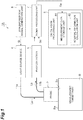
- FIG. 1 is a diagram conceptually illustrating a configuration of an embodiment of a biological measurement device and a biological measurement method.
- a biological measurement device 1A is a device for irradiating a measurement target part (for example, a head or a breast) B of a subject with light La which is near-infrared light, detecting diffused reflected light (measurement light) Lb propagating through the measurement target part to acquire internal information (an optical coefficient such as a scattering coefficient and an absorption coefficient, concentrations of various light absorption substances (for example, a tumor or blood hemoglobin), and the like) of the measurement target part B, converting the internal information into an image, and examining for the presence or absence of a tumor, cancer, or the like.
- the measurement light is not limited to the diffused reflected light.
- the biological measurement device 1A includes a probe 2 that is arranged on a surface of the measurement target part B.
- the probe 2 has a substantially rectangular parallelepiped shape having a predetermined direction as a longitudinal direction, and a width of the probe 2 in a lateral direction is a size that can be gripped with one hand.
- the probe 2 includes a contact surface 2a which is pressed against the measurement target part B at one end in a longitudinal direction. Further, the probe 2 holds one end of each of a plurality of irradiation optical fibers 11a for radiating light and a plurality of detection optical fibers 11b for detecting diffused reflected light. It should be noted that one optical fiber 11a and one optical fiber 11b are illustrated as representative in FIG. 1 . Respective end surfaces of the optical fibers 11a and 11b are fixed toward a surface Ba of the measurement target part B in a predetermined arrangement (layout) on the contact surface 2a.
- the biological measurement device 1A includes light source devices 4, photodetectors 5, a synchronization signal generation unit 6, a signal processing unit 7, and a calculation processing unit 8.
- the plurality of light source devices 4 are provided to correspond to the number of irradiation optical fibers 11a, and generate light La that is radiated to the measurement target part B.
- various light sources such as light emitting diodes (LEDs) and light sources such as laser diodes (LDs) can be used.
- an aspect of the light La output from the light source devices 4 is determined according to a method of calculating internal information in the calculation processing unit 8. For example, various types of light such as pulse light and continuous light (CW light) are adopted.
- pulsed light pulsed light having a short time width is used so that internal information of the measurement target part B can be measured. For example, a time width in a range of 1 nanosecond or less is selected.
- the light source devices 4 are optically coupled to the contact surface 2a of the probe 2 via the irradiation optical fiber 11a.
- the irradiation optical fibers 11a guide the light La emitted from the light source devices 4 to a predetermined irradiation position on the contact surface 2a of the probe 2.
- the light La is radiated toward the surface Ba of the measurement target part B from the output end. It should be noted that input of the light La to the measurement target part B is not limited to radiation of the light La toward the surface Ba of the measurement target part B.
- the light La radiated toward the measurement target part B propagates inside the measurement target part B to become diffused reflected light Lb.
- the diffused reflected light Lb is emitted from the surface Ba of the measurement target part B and output from the measurement target part B.
- the detection optical fibers 11b receive the diffused reflected light Lb emitted from the surface Ba of the measurement target part B at a predetermined light receiving position and guide the diffused reflected light Lb to the photodetectors 5.
- the plurality of photodetectors 5 are provided to correspond to the number of detection optical fibers 11b.
- the photodetectors 5 are optically coupled to the contact surface 2a of the probe 2 via the detection optical fibers 11b and detect an intensity of the diffused reflected light Lb obtained from the measurement target part B via the detection optical fibers 11b.
- the photodetectors 5 output a light detection signal Sd indicating the intensity of the diffused reflected light Lb.
- the light detection signal Sd output from the photodetectors 5 is input to the signal processing unit 7.
- the photodetectors 5 various photodetectors such as photomultiplier tubes, photodiodes, avalanche photodiodes, PIN photodiodes, and single photon avalanche diodes (SPADs) can be used. It should be noted that the photodetectors 5 can have spectral sensitivity characteristics capable of sufficiently detecting a wavelength band of the light La output from the light source devices 4. Further, it is possible to use the photodetectors 5 with high sensitivity or a high gain when the diffused reflected light Lb from the measurement target part B is weak.
- photomultiplier tubes photodiodes
- avalanche photodiodes avalanche photodiodes
- PIN photodiodes PIN photodiodes
- single photon avalanche diodes single photon avalanche diodes
- the synchronization signal generation unit 6 outputs a trigger signal St for causing the light source devices 4 and the signal processing unit 7 to operate in synchronization with each other (for matching an irradiation timing of the light La at each irradiation position with a detection timing of the diffused reflected light Lb at a corresponding light receiving position).
- Each of the light source devices 4 described above outputs the light La in synchronization with the timing indicated by the trigger signal St.
- the signal processing unit 7 is electrically connected to each of the photodetectors 5 and the synchronization signal generation unit 6, and receives the light detection signal Sd output from each photodetector 5 and the trigger signal St output from the synchronization signal generation unit 6.
- the signal processing unit 7 acquires the light detection signal Sd of each light receiving position corresponding to each irradiation position in synchronization with the timing indicated by the trigger signal St for each light source device 4.
- the signal processing unit 7 generates measurement data Da indicating a temporal change (measured waveform) in the light intensity of the diffused reflected light Lb obtained from the light receiving position corresponding to each irradiation position.
- the signal processing unit 7 provides the acquired measurement data Da to the calculation processing unit 8.
- the calculation processing unit (a calculation unit) 8 is realized by a computer including a calculation means such as a central processing unit (CPU), and a storage means such as a memory. Examples of such a computer include a personal computer, a smart device such as a smartphone or a tablet terminal, and a cloud server.
- the calculation processing unit 8 is electrically connected to the signal processing unit 7, analyzes the measurement data Da input from the signal processing unit 7 to calculate internal information of the measurement target part B, and performs conversion of the internal information into an image (image reconstruction).
- the calculation processing unit 8 includes a measurement data storage unit 81 and an internal information calculation unit 82.
- the measurement data storage unit 81 stores the measurement data Da input from the signal processing unit 7 to the calculation processing unit 8.
- Measurement data for reference that is used for calculation of the internal information may also be stored in the measurement data storage unit 81.
- the internal information calculation unit 82 analyzes the measurement data Da to calculate the internal information of the measurement target part B and converts the internal information into an image.
- the calculation of the internal information is performed by applying analysis calculation using, for example, time resolved spectroscopy (TRS) using a time resolved waveform of the diffused reflected light Lb, phase modulation spectroscopy (PMS) using modulated light as the light La, or a method using continuous wave (CW) light as the light La.
- TRS time resolved spectroscopy
- PMS phase modulation spectroscopy
- CW continuous wave
- the calculation processing unit 8 may further include a function of controlling at least one of components such as the light source devices 4, the photodetectors 5, and the signal processing unit 7.
- FIG. 2 is a plan view schematically illustrating the arrangement of the light irradiation portions 2c and the light receiving portions 2d.
- the light irradiation portions 2c are portions that irradiate the measurement target part B with light
- the plurality of light irradiation portions 2c are provided to correspond to the plurality of respective irradiation optical fibers 11a.
- Each of the light irradiation portions 2c is optically coupled to one end of a corresponding irradiation optical fiber 11a or is configured as one end of the corresponding irradiation optical fiber 11a.
- the light receiving portions 2d are portions that receive the diffused reflected light Lb emitted from the measurement target part B, and the plurality of light receiving portions 2d are provided to correspond to the plurality of respective detection optical fibers 11b.
- Each of the light receiving portions 2d is optically coupled to one end of a corresponding detection optical fiber 11b or configured as one end of the corresponding detection optical fiber 11b.
- a virtual square lattice D configured of a plurality of mutually parallel lines extending in an X direction (a first direction) and aligned in a Y direction (a second direction) and a plurality of mutually parallel lines extending in the Y direction and aligned in the X direction is set on the contact surface 2a.
- the X direction and the Y direction are orthogonal to each other.
- a lattice interval of this square lattice D is d.
- d is 1 cm.
- This square lattice D includes a plurality of lattice points aligned at substantially equal intervals d in the X direction and the Y direction.
- the interval d can be set to be equal to or greater than 0.5 cm and equal to or smaller than 1 cm.
- the plurality of light irradiation portions 2c are arranged at some of the plurality of lattice points and the plurality of light receiving portions 2d are arranged at other lattice points among the plurality of lattice points.
- lattice points in five rows in the X direction and five columns in the Y direction are shown in FIG. 2
- the light irradiation portion 2c are provided at 13 lattice points among the 25 lattice points
- the light receiving portions 2d are provided at the other 12 lattice points.
- a center position of each light irradiation portion 2c matches a position of the corresponding lattice point
- a center position of each light receiving portion 2d matches a position of the corresponding lattice point.
- the light irradiation portions 2c and the light receiving portions 2d are arranged on the basis of a predetermined rule. That is, the light receiving portions 2d are necessarily arranged at each lattice point separated by a distance A ⁇ d (A is an integer equal to or greater than 2 and A is 2 in FIG. 2 ) in the X direction and each lattice point separated by the distance A ⁇ d in the Y direction from the lattice point at which the light irradiation portion 2c is arranged.
- a ⁇ d is an integer equal to or greater than 2 and A is 2 in FIG. 2
- the light irradiation portion 2c is necessarily arranged at each lattice point separated by the distance A ⁇ d in the X direction and each lattice point separated by the distance A ⁇ d in the Y direction from each lattice point at which the light receiving portion 2d is arranged.
- the light irradiation portion 2c is arranged at two corners on one of diagonal lines, and the light receiving portion 2d is arranged at two corners on the other of the diagonal lines, as illustrated in FIGS. 3(a) and 3(b) .
- the light irradiation portions 2c and the light receiving portions 2d are arranged so that the light irradiation portions 2c and the light receiving portions 2d are located on the lattice points of the square lattice D. It should be noted that a square S indicating one basic pattern is shown in FIG. 2 .
- the internal information calculation unit 82 calculates internal information of the measurement target part B on the basis of a result of detection of the diffused reflected light Lb obtained for each of combinations of the light irradiation portions 2c and the light receiving portions 2d. Specifically, as illustrated in FIG. 4 , the internal information calculation unit 82 calculates the internal information on the basis of a detection result of the diffused reflected light Lb obtained by a plurality of combinations (arrows A1 in FIG. 4 ) of the light irradiation portions 2c and the light receiving portions 2d separated by the distance A ⁇ d in the X direction and a plurality of combinations (arrows A2 in FIG.
- a distance between irradiation and light reception in a set of the light irradiation portions 2c and the light receiving portions 2d that is used for detection of the diffused reflected light Lb is constant as A ⁇ d.
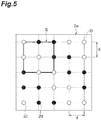
- FIG. 5 is a plan view schematically illustrating another example of the arrangement of the light irradiation portions 2c and the light receiving portions 2d.
- the arrangement of the light irradiation portions 2c and the light receiving portions 2d is different from that in FIG. 2 .
- the distance between irradiation and light reception of the light irradiation portions 2c and the light receiving portion 2d is 3 ⁇ d.
- a length of the lattice interval d can be set to 2/3 of the lattice interval d in FIG. 2 .
- the distance between irradiation and light reception of the light irradiation portions 2c and the light receiving portions 2d is 4 ⁇ d.
- the length of the lattice interval d can be set to 1/2 of the lattice interval d in FIG. 2 .
- FIG. 12 is a flowchart illustrating a biological measurement method in the biological measurement device 1A.
- the contact surface 2a is first pressed against the surface Ba of the measurement target part B (arrangement step S1).
- One light irradiation portion 2c irradiates the measurement target part B with the light La (light input step S2).
- the light La propagates through the measurement target part B and is output as diffused reflected light Lb to the plurality of light receiving portions 2d.
- the diffused reflected light Lb output to each light receiving portion 2d is detected by the photodetector 5 corresponding to the light receiving portion 2d.
- Each photodetector 5 outputs the light detection signal Sd to the signal processing unit 7.
- the signal processing unit 7 processes the light detection signal Sd corresponding to the light receiving portion 2d located at a position separated by the distance A ⁇ d (A is an integer equal to or greater than 2) from the light irradiation portion 2c among the light detection signals Sd output from the respective photodetectors 5, and provides the measurement data Da as a detection result to the calculation processing unit 8 (detection step S3).
- A is an integer equal to or greater than 2
- measurement in the next light irradiation portion 2c is performed. These operations are repeated until the measurement at all set light irradiation portions 2c ends (step S4).
- the signal processing unit 7 may not receive the light detection signal Sd corresponding to a light receiving portion 2d that is not in the relationship described above or may not process the light detection signal Sd.
- the internal information calculation unit 82 calculates internal information of the measurement target part B by performing analysis calculation such as the TRS or the PMS on the basis of the obtained detection result (calculation step S5). Therefore, the internal information calculation unit 82 can calculate the internal information of the measurement target part B on the basis of the detection result corresponding to the combination in which an interval between the light irradiation portion 2c and the light receiving portion 2d becomes the distance A ⁇ d.
- the internal information calculation unit 82 obtains an image (a CT image) of a three-dimensional distribution of an optical coefficient or concentrations of various light absorption substances in a range of depth from 0 cm to, for example, 3 to 4 cm in a region of the measurement target part B (for example, a region of 5 cm ⁇ 5 cm) covered by the contact surface 2a of the probe 2.
- an example in which the light absorption substance concentration calculated by the internal information calculation unit 82 is actually formed as an image will be described.
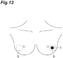
- FIG. 13 is a front view illustrating left and right breasts of a breast cancer patient including a measurement target part B which is a measurement target, and a tumor E having a diameter of about 20 mm is present in the left breast.
- FIGS. 14(a) and 14(b) illustrate a result of measuring the measurement target part B illustrated in FIG. 13 and forming a CT image.
- FIG. 14(a) illustrates a CT image regarding the right breast in which a tumor E is not generated
- FIG. 14(b) illustrates a CT image regarding the left breast including a tumor E. It can be seen from a comparison of the CT images with each other that, in FIG. 14(b) , an image E1 regarding the tumor E, which is not illustrated in FIG. 14(a) , is clearly included.
- the internal information calculation unit 82 can calculate an optical coefficient or concentrations of various light absorption substances in a lattice form at intervals (for example, intervals of 1 cm) equal to the lattice interval d using, for example, TRS of one channel and map an obtained value as a two-dimensional image. That is, it is possible to obtain both a three-dimensional image (a CT image) and a two-dimensional image (a mapping image) in one measurement.
- FIGS. 15(a) and 15(b) illustrate a two-dimensional mapping image obtained by actually measuring the measurement target part B illustrated in FIG. 13 .
- FIG. 15(a) illustrates a two-dimensional mapping image regarding the right breast in which the tumor E is not generated
- FIG. 15(b) illustrate a two-dimensional mapping image regarding the left breast including the tumor E. It can be seen from a comparison of the two-dimensional mapping images with each other that an image E2 regarding the tumor E, which is not present in FIG. 15(a) , is clearly included in FIG. 15(b) .
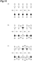
- FIG. 16(a) to 16(c) are diagrams illustrating a process of the embodiment.
- pairs of the light irradiation portion 2c and the light receiving portion 2d having a predetermined distance between irradiation and light reception are equally aligned in a direction orthogonal to an alignment direction of the pairs.
- only measurement data in the alignment direction (a vertical direction in FIG. 16 ) of the light irradiation portion 2c and the light receiving portion 2d can be obtained (arrows A3 in FIG. 16(a) ), and measurement data in a horizontal direction is insufficient.
- FIG. 16(a) the alignment direction of the light irradiation portion 2c and the light receiving portion 2d
- the light irradiation portion 2c and the light receiving portion 2d of the pair located at a center are interchanged.
- measurement data in a horizontal direction is obtained (arrows A4 in FIG. 16(b) ), in addition to measurement data in a vertical direction illustrated in FIG. 16(a) .
- the light irradiation portion 2c and the light receiving portion 2d in the pair adjacent to the pair located at the center are interchanged.
- measurement data in the horizontal direction further increases (arrows A5 in FIG. 16(c) ), in addition to the measurement data illustrated in FIG. 16(b) .
- the light irradiation portions 2c and the light receiving portions 2d are arranged according to the combination of the basic patterns illustrated in FIGS. 3(a) and 3(b) in order to acquire the measurement data in the horizontal direction (the X direction in FIG. 2 ) and the measurement data in the vertical direction (the Y direction in FIG. 2 ) as much as possible as the measurement data at the predetermined distance between irradiation and light receiving. It has been found that a density of measurement data becomes uniform and measurement sensitivity becomes substantially uniform by arranging the light irradiation portions 2c and the light receiving portions 2d to be aligned in a square lattice form having equal intervals in the vertical and horizontal directions.
- a density of the combinations of the light irradiation portions 2c and the light receiving portions 2d becomes uniform within the contact surface 2a by arranging a plurality of light irradiation portions 2c and a plurality of light receiving portions 2d on the contact surface 2a as illustrated in FIGS. 2 and 5 to 11 and setting the combinations of the light irradiation portions 2c and light receiving portions 2d for detecting the diffused reflected light Lb as described above. Therefore, it is possible to improve the uniformity of measurement sensitivity and obtain a clearer image.
- a configuration in which the combinations of the light irradiation portions and the light receiving portions are made uniform can also be realized by using a coaxial fiber in which both light irradiation and light reception can be performed at one end.
- coaxial fibers are required by the number of lattice points (25 lattice points in FIG. 2 ), and the number of light source devices and the number of photodetectors are also required by the number of lattice points.
- measurement with the same sensitivity can be realized with a smaller number of light irradiation portions 2c and light receiving portions 2d, it is possible to avoid complication of the device configuration and greatly suppress manufacturing cost.
- the constant A is the integer equal to or greater than 2.
- the constant A is 1 (that is, when the lattice interval d is equal to the distance between irradiation and light reception)
- an intensity of light incident on the light receiving portion 2d may be too high for example, when a concentration of a metabolite inside a body is obtained using the TRS, and there is concern that a dynamic range is deteriorated.
- the lattice interval d is increased in order to solve this problem, the number of pieces of measurement data obtained decreases, and therefore, a reconstructed image deteriorates.
- the constant A is equal to or greater than 2, it is possible to acquire a sufficient number of pieces of measurement data while suppressing an intensity of light incident on the light receiving portions 2d. Therefore, it is possible to improve measurement accuracy and acquire a clearer image.
- FIGS. 23(a) and 23(b) are diagrams illustrating an arrangement of light irradiators and light receivers described in Patent Literature 1, in which combinations of the light irradiators and the light receivers, and measurement points in each combination are illustrated.
- light irradiators and light receivers are arranged so that measurement points are aligned vertically and horizontally at predetermined intervals.
- an alignment direction of the light irradiator and the light receiver is only one of the vertical direction and a horizontal direction. In order to further improve the accuracy of the measurement, it is ideal to cause light to propagate through one measurement point from as many directions as possible.
- the biological measurement device 1A of the embodiment solves the problem of the device described in Patent Literature 1 as described above and obtains a clearer image by improving the uniformity of the measurement sensitivity.
- the plurality of light irradiation portions 2c may sequentially input light to the measurement target part B, as in the embodiment. Accordingly, it is possible to avoid interference between light beams that are input from the plurality of light irradiation portions 2c and improve S/N.
- the integer A may be 2, as in the embodiment. Accordingly, it is possible to increase the number of combinations of the plurality of light irradiation portions 2c and the plurality of light receiving portions 2d. Therefore, the uniformity of the measurement sensitivity and the resolution are further improved and a clearer image can be obtained.
- the lattice interval d may be equal to or greater than 0.5 cm and less than or equal to 1 cm, as in the present embodiment. In this case, it is possible to improve resolution while suppressing saturation at the time of light detection.
- the calculation processing unit 8 may create a two-dimensional image or a three-dimensional image on the basis of the internal information, as in the embodiment. According to the embodiment, since the density of the combinations of the light irradiation portions 2c and the light receiving portions 2d becomes uniform as described above, it is possible to create a clear image.
- the present inventor prepared a probe 2 having the arrangement of the light irradiation portions 2c and the light receiving portions 2d illustrated in FIG. 2 and performed a verification experiment shown below. It should be noted that the lattice interval d was 10 mm and the constant A was 2.
- a reconstructed image regarding absorption coefficient was obtained by measuring a solid phantom including an absorber therein using only a detection result of the diffused reflected light Lb (that is, measurement data in which the distance between irradiation and light reception is 20 mm) obtained by a plurality of combinations (the arrows A1 in FIG. 4 ) of the light irradiation portions 2c and the light receiving portions 2d separated by a distance of 20 mm in the X direction and a plurality of combinations (the arrows A2 in FIG. 4 ) of the light irradiation portions 2c and the light receiving portions 2d separated by a distance of 20 mm in the Y direction.
- FIGS. 17 , 18(a) , 18(b) , 19(a), and 19(b) are diagrams illustrating combinations of the light irradiation portions 2c and the light receiving portions 2d in the comparative example, and a double arrow in each diagram indicate a combination of the light irradiation portion 2c and the light receiving portion 2d.
- distances between irradiation and light reception are 2.24 cm, 3 cm, 3.16 cm, 3.61 cm, and 4.47 cm, respectively.
- one reconstructed image was created by using measurement data of the distances between irradiation and light reception together.
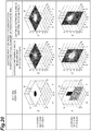
- FIG. 20 is a diagram illustrating a position and a shape of an absorber F inside a solid phantom (two upper and lower diagrams at a left end), CT images (two upper and lower diagrams at a center) indicating a three-dimensional distribution of an absorption coefficient inside the solid phantom acquired in the comparative example, and CT images (two upper and lower diagrams on a right end) indicating a three-dimensional distribution of the absorption coefficient inside the solid phantom acquired in the example.
- CT images two upper and lower diagrams on a right end
- a pixel value is small (that is, sensitivity is low) and the position and the size of the absorber F inside the solid phantom cannot be accurately measured.
- the pixel value is great (that is, the sensitivity is high) in spite of the number of pieces of measurement data being half or smaller than the number in the comparative example, and the position and the size of the absorber F inside the solid phantom can be accurately measured.
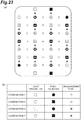
- the example was compared with the comparative example when the position of the absorber F was shifted by 1 cm in the Y direction from the position illustrated in FIG. 20 ( FIG. 21 ) and when the position of the absorber F was shifted by 1 cm in the X direction ( FIG. 22 ).
- the sensitivity was higher and the uniformity in the lateral direction was improved as compared with the comparative example.
- the biological measurement device and the biological measurement method according to the aspect of the present invention are not limited to the above-described embodiments, and various other modifications are possible.
- the arrangement of the light irradiation portions and the light receiving portions is not limited to each of the forms illustrated in FIG. 2 and FIGS. 5 to 11 , and can be various arrangements according to the rule described in the above embodiment.
- the probe 2 may include the light source device 4 and the photodetector 5, the light source device 4 may be arranged in the light irradiation portion 2c, and the photodetector 5 may be arranged in the light receiving portion 2d.
- the biological measurement device is a biological measurement device that inputs light to a measurement target part of a subject and acquires internal information of the measurement target part by detecting measurement light propagating through the measurement target part
- the biological measurement device including: a probe including a contact surface that includes a plurality of light input portions that input the light to the measurement target part and a plurality of light receiving portions that receive the measurement light output from the measurement target part, the contact surface being pressed against the measurement target part; and a calculation unit that calculates the internal information on the basis of a result of detecting the measurement light obtained for each combination of the light input portion and the light receiving portion, wherein the light input portions and the light receiving portions may be arranged at some lattice points among a plurality of lattice points included in the lattice having a lattice interval d in a first direction and a second direction orthogonal to each other, and a plurality of light receiving portions may be arranged at other lattice points among the plurality of lattice points, the light receiving
Landscapes
- Health & Medical Sciences (AREA)
- Life Sciences & Earth Sciences (AREA)
- Physics & Mathematics (AREA)
- Public Health (AREA)
- Surgery (AREA)
- Veterinary Medicine (AREA)
- Pathology (AREA)
- Engineering & Computer Science (AREA)
- Biomedical Technology (AREA)
- Heart & Thoracic Surgery (AREA)
- Medical Informatics (AREA)
- Molecular Biology (AREA)
- General Health & Medical Sciences (AREA)
- Animal Behavior & Ethology (AREA)
- Biophysics (AREA)
- Spectroscopy & Molecular Physics (AREA)
- Optics & Photonics (AREA)
- Nuclear Medicine, Radiotherapy & Molecular Imaging (AREA)
- Radiology & Medical Imaging (AREA)
- Measurement Of The Respiration, Hearing Ability, Form, And Blood Characteristics Of Living Organisms (AREA)
- Investigating Or Analysing Materials By Optical Means (AREA)
Abstract
Description
- An aspect of the present invention relates to a biological measurement device and a biological measurement method.
-
Patent Literature 1 describes a technology regarding a biological optical measurement device. In the device described in this Literature, a plurality of light irradiators that irradiate an examination target body with light and a plurality of light receivers that receive the light radiated from the light irradiator and propagating through the examination target body are alternately arranged on the examination target body. The device sets a substantial middle point position of the light irradiator and the light receiver as a measurement point and measures a concentration of a metabolite inside the examination target body and a change in the concentration on the basis of a signal detected by the light receiver. -
- Patent Literature 1: Japanese Unexamined Patent Publication No.
2001-178708 - Patent Literature 2: Japanese Unexamined Patent Publication No.
2005-049238 - A device using so-called diffuse optical tomography (DOT) that obtains internal information using light absorption characteristics of a living body has been proposed as a device that noninvasively measures internal information of a living body such as a head or a breast. In such a measurement device, a part of a living body that is a measurement target can be irradiated with light from a predetermined irradiation position, light propagating while being scattered inside the part can be detected at a predetermined detection position, and internal information of the part, that is, information (a position, a concentration, or the like) on a light absorber such as a tumor or hemoglobin present inside the part can be obtained from a result of measurement of an intensity, a time waveform, or the like of the light.
- In such a measurement device, a scheme of performing irradiation of a measurement target part with light and detection of diffused light using a compact probe that can be gripped is conceivable. That is, this scheme is a scheme using, for example, diffused reflected light among light diffused inside the measurement target part for measurement. With such a scheme, it is possible to realize a simpler measurement device that is easier to use. However, in this scheme, since the irradiation with the light and the detection of the diffused light are performed in a limited narrow region on a surface of the measurement target part, there is a problem that uniformity of measurement sensitivity easily becomes degraded.
- An aspect of the present invention has been made in view of such problems, and an object of the present invention is to provide a probe-type biological measurement device and a biological measurement method that can improve uniformity of measurement sensitivity.
- A biological measurement device according to an aspect of the present invention is a biological measurement device that inputs light to a measurement target part of a subject and acquires internal information of the measurement target part by detecting measurement light propagating through the measurement target part, the biological measurement device including: a probe including a contact surface that includes a plurality of light input portions that input the light to the measurement target part and a plurality of light receiving portions that receive the measurement light output from the measurement target part, the contact surface being pressed against the measurement target part; and a calculation unit that calculates the internal information on the basis of a result of detecting the measurement light obtained for each combination of the light input portion and the light receiving portion. The plurality of light input portions and the plurality of light receiving portions constitute lattices having an interval d, and along a first direction and a second direction orthogonal to each other on the contact surface, at least some of the plurality of light receiving portions are located at a position separated by a distance A×d (A is an integer equal to or greater than 2) in the first direction and the second direction from the light input portion, and at least some of the plurality of light input portions are located at a position separated by the distance A×d in the first direction and the second direction from the light receiving portion. The combination is a combination in which an interval between the light input portion and the light receiving portion is the distance A×d.
- Further, a biological measurement method according to an aspect of the present invention is a biological measurement method for inputting light to a measurement target part of a subject and acquiring internal information of the measurement target part by detecting measurement light propagating through the measurement target part, the biological measurement method including a step of disposing a probe including a contact surface that includes a plurality of light input portions and a plurality of light receiving portions at the measurement target part (a disposition step); a step of inputting the light from one of the plurality of light input portions to the measurement target part (a light input step); a step of detecting the measurement light received by the light receiving portion located at a position separated by a distance A×d (A is an integer equal to or greater than 2) from the light input portion that has input the light among the plurality of light receiving portions when an interval between lattices configured of the plurality of light input portions and the plurality of light receiving portions on the contact surface is d, and outputting a detection result (a detection step); and a step of calculating the internal information on the basis of the detection result (a calculation step).
- According to this biological measurement device and biological measurement method, since the internal information is calculated by a combination in which the distance between the light input portion and the light receiving portion is the distance A×d, a density of the combinations of the light input portions and the light receiving portions is uniform, and uniformity of measurement sensitivity can be improved.
- The plurality of light input portions may sequentially input the light to the measurement target part. In this case, S/N can be improved.
- The integer A may be 2. In this case, a large number of combinations can be obtained.
- The lattice interval d may be equal to or greater than 0.5 cm and less than or equal to 1 cm. In this case, it is possible to improve resolution while suppressing saturation at the time of light detection.
- The calculation unit (the calculation step) may create a two-dimensional image or a three-dimensional image on the basis of the internal information. Since a density of the combinations of the light input portions and the light receiving portions is uniform, it is possible to create a clear image.
- According to the aspect of the present invention, it is possible to provide a probe-type biological measurement device and a biological measurement method that can improve uniformity of measurement sensitivity.
-
-
FIG. 1 is a diagram conceptually illustrating a configuration of an embodiment of a biological measurement device. -
FIG. 2 is a plan view schematically illustrating an arrangement of a light irradiation portion and a light receiving portion. -
FIGS. 3(a) and 3(b) are diagrams illustrating basic patterns of an arrangement of light irradiation portions and light receiving portions. -
FIG. 4 is a diagram illustrating combinations of light irradiation portions and light receiving portions. -
FIG. 5 is a plan view schematically illustrating an example of an arrangement of light irradiation portions and light receiving portions. -
FIG. 6 is a plan view schematically illustrating an example of an arrangement of light irradiation portions and light receiving portions. -
FIG. 7 is a plan view schematically illustrating an example of an arrangement of light irradiation portions and light receiving portions. -
FIG. 8 is a plan view schematically illustrating an example of an arrangement of light irradiation portions and light receiving portions. -
FIG. 9 is a plan view schematically illustrating an example of an arrangement of light irradiation portions and light receiving portions. -
FIG. 10 is a plan view schematically illustrating an example of an arrangement of light irradiation portions and light receiving portions. -
FIG. 11 is a plan view schematically illustrating an example of an arrangement of light irradiation portions and light receiving portions. -
FIG. 12 is a flowchart illustrating a biological measurement method according to an embodiment. -
FIG. 13 is a front view illustrating left and right breasts of a breast cancer patient including a measurement target part. -
FIGS. 14(a) and 14(b) illustrate a result of measuring the measurement target part illustrated inFIG. 13 and obtaining a CT image. -
FIGS. 15(a) and 15(b) illustrate a two-dimensional mapping image obtained by measuring the measurement target part illustrated inFIG. 13 . -
FIGS. 16(a) to 16(c) are diagrams illustrating a process of an embodiment. -
FIG. 17 is a diagram illustrating combinations of light irradiation portions and light receiving portions in a comparative example. -
FIGS. 18(a) and 18(b) are diagrams illustrating combinations of light irradiation portions and light receiving portions in the comparative example. -
FIGS. 19(a) and 19(b) are diagrams illustrating combinations of the light irradiation portions and the light receiving portions in the comparative example. -
FIG. 20 is a diagram illustrating a position and a shape of an absorber inside a solid phantom, CT images indicating a three-dimensional distribution of an absorption coefficient inside the solid phantom acquired in a comparative example, and CT images indicating a three-dimensional distribution of an absorption coefficient inside a solid phantom acquired in the example. -
FIG. 21 is a diagram illustrating a position and a shape of an absorber inside a solid phantom, CT images indicating a three-dimensional distribution of an absorption coefficient inside the solid phantom acquired in a comparative example, and CT images indicating a three-dimensional distribution of an absorption coefficient inside a solid phantom acquired in the example. -
FIG. 22 is a diagram illustrating a position and a shape of an absorber inside a solid phantom, CT images indicating a three-dimensional distribution of an absorption coefficient inside the solid phantom acquired in a comparative example, and CT images indicating a three-dimensional distribution of an absorption coefficient inside a solid phantom acquired in the example. -
FIGS. 23(a) and 23(b) are diagrams illustrating an arrangement of light irradiators and light receivers described inPatent Literature 1, combinations of the light irradiators and the light receivers, and measurement points in each combination. - Hereinafter, embodiments of a biological measurement device and a biological measurement method will be described in detail with reference to the accompanying drawings. It should be noted that in the description of the drawings, the same elements are denoted by the same reference numerals, and repeated description thereof is omitted.
-
FIG. 1 is a diagram conceptually illustrating a configuration of an embodiment of a biological measurement device and a biological measurement method. Abiological measurement device 1A according to the present embodiment is a device for irradiating a measurement target part (for example, a head or a breast) B of a subject with light La which is near-infrared light, detecting diffused reflected light (measurement light) Lb propagating through the measurement target part to acquire internal information (an optical coefficient such as a scattering coefficient and an absorption coefficient, concentrations of various light absorption substances (for example, a tumor or blood hemoglobin), and the like) of the measurement target part B, converting the internal information into an image, and examining for the presence or absence of a tumor, cancer, or the like. It should be noted that the measurement light is not limited to the diffused reflected light. - As illustrated in
FIG. 1 , thebiological measurement device 1A includes aprobe 2 that is arranged on a surface of the measurement target part B. Theprobe 2 has a substantially rectangular parallelepiped shape having a predetermined direction as a longitudinal direction, and a width of theprobe 2 in a lateral direction is a size that can be gripped with one hand. Theprobe 2 includes acontact surface 2a which is pressed against the measurement target part B at one end in a longitudinal direction. Further, theprobe 2 holds one end of each of a plurality of irradiationoptical fibers 11a for radiating light and a plurality of detectionoptical fibers 11b for detecting diffused reflected light. It should be noted that oneoptical fiber 11a and oneoptical fiber 11b are illustrated as representative inFIG. 1 . Respective end surfaces of theoptical fibers contact surface 2a. - Further, the
biological measurement device 1A includeslight source devices 4,photodetectors 5, a synchronizationsignal generation unit 6, asignal processing unit 7, and acalculation processing unit 8. The plurality oflight source devices 4 are provided to correspond to the number of irradiationoptical fibers 11a, and generate light La that is radiated to the measurement target part B. As thelight source devices 4, various light sources such as light emitting diodes (LEDs) and light sources such as laser diodes (LDs) can be used. Further, an aspect of the light La output from thelight source devices 4 is determined according to a method of calculating internal information in thecalculation processing unit 8. For example, various types of light such as pulse light and continuous light (CW light) are adopted. As the pulsed light, pulsed light having a short time width is used so that internal information of the measurement target part B can be measured. For example, a time width in a range of 1 nanosecond or less is selected. Thelight source devices 4 are optically coupled to thecontact surface 2a of theprobe 2 via the irradiationoptical fiber 11a. The irradiationoptical fibers 11a guide the light La emitted from thelight source devices 4 to a predetermined irradiation position on thecontact surface 2a of theprobe 2. The light La is radiated toward the surface Ba of the measurement target part B from the output end. It should be noted that input of the light La to the measurement target part B is not limited to radiation of the light La toward the surface Ba of the measurement target part B. - The light La radiated toward the measurement target part B propagates inside the measurement target part B to become diffused reflected light Lb. The diffused reflected light Lb is emitted from the surface Ba of the measurement target part B and output from the measurement target part B. The detection
optical fibers 11b receive the diffused reflected light Lb emitted from the surface Ba of the measurement target part B at a predetermined light receiving position and guide the diffused reflected light Lb to thephotodetectors 5. - The plurality of
photodetectors 5 are provided to correspond to the number of detectionoptical fibers 11b. Thephotodetectors 5 are optically coupled to thecontact surface 2a of theprobe 2 via the detectionoptical fibers 11b and detect an intensity of the diffused reflected light Lb obtained from the measurement target part B via the detectionoptical fibers 11b. Thephotodetectors 5 output a light detection signal Sd indicating the intensity of the diffused reflected light Lb. The light detection signal Sd output from thephotodetectors 5 is input to thesignal processing unit 7. As thephotodetectors 5, various photodetectors such as photomultiplier tubes, photodiodes, avalanche photodiodes, PIN photodiodes, and single photon avalanche diodes (SPADs) can be used. It should be noted that thephotodetectors 5 can have spectral sensitivity characteristics capable of sufficiently detecting a wavelength band of the light La output from thelight source devices 4. Further, it is possible to use thephotodetectors 5 with high sensitivity or a high gain when the diffused reflected light Lb from the measurement target part B is weak. - The synchronization
signal generation unit 6 outputs a trigger signal St for causing thelight source devices 4 and thesignal processing unit 7 to operate in synchronization with each other (for matching an irradiation timing of the light La at each irradiation position with a detection timing of the diffused reflected light Lb at a corresponding light receiving position). Each of thelight source devices 4 described above outputs the light La in synchronization with the timing indicated by the trigger signal St. - The
signal processing unit 7 is electrically connected to each of thephotodetectors 5 and the synchronizationsignal generation unit 6, and receives the light detection signal Sd output from eachphotodetector 5 and the trigger signal St output from the synchronizationsignal generation unit 6. Thesignal processing unit 7 acquires the light detection signal Sd of each light receiving position corresponding to each irradiation position in synchronization with the timing indicated by the trigger signal St for eachlight source device 4. Thesignal processing unit 7 generates measurement data Da indicating a temporal change (measured waveform) in the light intensity of the diffused reflected light Lb obtained from the light receiving position corresponding to each irradiation position. Thesignal processing unit 7 provides the acquired measurement data Da to thecalculation processing unit 8. - The calculation processing unit (a calculation unit) 8 is realized by a computer including a calculation means such as a central processing unit (CPU), and a storage means such as a memory. Examples of such a computer include a personal computer, a smart device such as a smartphone or a tablet terminal, and a cloud server. The
calculation processing unit 8 is electrically connected to thesignal processing unit 7, analyzes the measurement data Da input from thesignal processing unit 7 to calculate internal information of the measurement target part B, and performs conversion of the internal information into an image (image reconstruction). Thecalculation processing unit 8 includes a measurementdata storage unit 81 and an internalinformation calculation unit 82. The measurementdata storage unit 81 stores the measurement data Da input from thesignal processing unit 7 to thecalculation processing unit 8. Measurement data for reference that is used for calculation of the internal information may also be stored in the measurementdata storage unit 81. The internalinformation calculation unit 82 analyzes the measurement data Da to calculate the internal information of the measurement target part B and converts the internal information into an image. The calculation of the internal information is performed by applying analysis calculation using, for example, time resolved spectroscopy (TRS) using a time resolved waveform of the diffused reflected light Lb, phase modulation spectroscopy (PMS) using modulated light as the light La, or a method using continuous wave (CW) light as the light La. As a detailed method of calculating the internal information, for example, a method described inPatent Literature 2 can be used. It should be noted that thecalculation processing unit 8 may further include a function of controlling at least one of components such as thelight source devices 4, thephotodetectors 5, and thesignal processing unit 7. - Here, an arrangement of light irradiation portions (light input portions) 2c and
light receiving portions 2d on thecontact surface 2a of theprobe 2 will be described in detail.FIG. 2 is a plan view schematically illustrating the arrangement of thelight irradiation portions 2c and thelight receiving portions 2d. It should be noted that thelight irradiation portions 2c are portions that irradiate the measurement target part B with light, and the plurality oflight irradiation portions 2c are provided to correspond to the plurality of respective irradiationoptical fibers 11a. Each of thelight irradiation portions 2c is optically coupled to one end of a corresponding irradiationoptical fiber 11a or is configured as one end of the corresponding irradiationoptical fiber 11a. Thelight receiving portions 2d are portions that receive the diffused reflected light Lb emitted from the measurement target part B, and the plurality oflight receiving portions 2d are provided to correspond to the plurality of respective detectionoptical fibers 11b. Each of thelight receiving portions 2d is optically coupled to one end of a corresponding detectionoptical fiber 11b or configured as one end of the corresponding detectionoptical fiber 11b. - As illustrated in
FIG. 2 , a virtual square lattice D configured of a plurality of mutually parallel lines extending in an X direction (a first direction) and aligned in a Y direction (a second direction) and a plurality of mutually parallel lines extending in the Y direction and aligned in the X direction is set on thecontact surface 2a. The X direction and the Y direction are orthogonal to each other. A lattice interval of this square lattice D is d. For example, d is 1 cm. This square lattice D includes a plurality of lattice points aligned at substantially equal intervals d in the X direction and the Y direction. It should be noted that saturation is likely to occur at the time of light detection when the interval d is small, and resolution becomes degraded when the interval d is great. Therefore, the interval d can be set to be equal to or greater than 0.5 cm and equal to or smaller than 1 cm. - The plurality of
light irradiation portions 2c are arranged at some of the plurality of lattice points and the plurality oflight receiving portions 2d are arranged at other lattice points among the plurality of lattice points. As an example, lattice points in five rows in the X direction and five columns in the Y direction (a total of 25 lattice points) are shown inFIG. 2 , thelight irradiation portion 2c are provided at 13 lattice points among the 25 lattice points, and thelight receiving portions 2d are provided at the other 12 lattice points. A center position of eachlight irradiation portion 2c matches a position of the corresponding lattice point, and a center position of each light receivingportion 2d matches a position of the corresponding lattice point. - The
light irradiation portions 2c and thelight receiving portions 2d are arranged on the basis of a predetermined rule. That is, thelight receiving portions 2d are necessarily arranged at each lattice point separated by a distance A×d (A is an integer equal to or greater than 2 and A is 2 inFIG. 2 ) in the X direction and each lattice point separated by the distance A×d in the Y direction from the lattice point at which thelight irradiation portion 2c is arranged. Further, thelight irradiation portion 2c is necessarily arranged at each lattice point separated by the distance A×d in the X direction and each lattice point separated by the distance A×d in the Y direction from each lattice point at which thelight receiving portion 2d is arranged. In other words, in a square of which a length of a side is (A×d), thelight irradiation portion 2c is arranged at two corners on one of diagonal lines, and thelight receiving portion 2d is arranged at two corners on the other of the diagonal lines, as illustrated inFIGS. 3(a) and 3(b) . By setting such an arrangement as a basic pattern and combining a plurality of basic patterns, thelight irradiation portions 2c and thelight receiving portions 2d are arranged so that thelight irradiation portions 2c and thelight receiving portions 2d are located on the lattice points of the square lattice D. It should be noted that a square S indicating one basic pattern is shown inFIG. 2 . - The internal
information calculation unit 82 calculates internal information of the measurement target part B on the basis of a result of detection of the diffused reflected light Lb obtained for each of combinations of thelight irradiation portions 2c and thelight receiving portions 2d. Specifically, as illustrated inFIG. 4 , the internalinformation calculation unit 82 calculates the internal information on the basis of a detection result of the diffused reflected light Lb obtained by a plurality of combinations (arrows A1 inFIG. 4 ) of thelight irradiation portions 2c and thelight receiving portions 2d separated by the distance A×d in the X direction and a plurality of combinations (arrows A2 inFIG. 4 ) of thelight irradiation portion 2c and thelight receiving portion 2d separated by a distance A×d in the Y direction. Therefore, in the present embodiment, a distance between irradiation and light reception in a set of thelight irradiation portions 2c and thelight receiving portions 2d that is used for detection of the diffused reflected light Lb is constant as A×d. - It should be noted that the arrangement of the
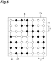
light irradiation portions 2c and thelight receiving portions 2d may be in accordance with a predetermined rule and is not limited to the arrangement illustrated inFIG. 2 .FIG. 5 is a plan view schematically illustrating another example of the arrangement of thelight irradiation portions 2c and thelight receiving portions 2d. The example illustrated inFIG. 5 is a case in which constant A = 2 as in the case ofFIG. 2 and thelight irradiation portions 2c and thelight receiving portions 2d are arranged on the basis of the same rule as inFIG. 2 . However, the arrangement of thelight irradiation portions 2c and thelight receiving portions 2d is different from that inFIG. 2 . Further, examples illustrated inFIGS. 6 to 8 correspond to a case in which constant A = 3, and thelight irradiation portions 2c and thelight receiving portions 2d are arranged on the basis of the same rule as inFIG. 2 . In the examples illustrated inFIGS. 6 to 8 , the distance between irradiation and light reception of thelight irradiation portions 2c and thelight receiving portion 2d is 3×d. When the distance between irradiation and light reception is made equal to that inFIG. 2 , a length of the lattice interval d can be set to 2/3 of the lattice interval d inFIG. 2 . Further, Examples illustrated inFIGS. 9 to 11 correspond to a case in which constant A = 4, and thelight irradiation portions 2c and thelight receiving portions 2d are arranged on the basis of the same rule as inFIG. 2 . In the examples illustrated inFIGS. 9 to 11 , the distance between irradiation and light reception of thelight irradiation portions 2c and thelight receiving portions 2d is 4×d. When the distance between irradiation and light reception is made equal to that inFIG. 2 , the length of the lattice interval d can be set to 1/2 of the lattice interval d inFIG. 2 . -
FIG. 12 is a flowchart illustrating a biological measurement method in thebiological measurement device 1A. As illustrated inFIG. 12 , in the biological measurement method of the embodiment, thecontact surface 2a is first pressed against the surface Ba of the measurement target part B (arrangement step S1). Onelight irradiation portion 2c irradiates the measurement target part B with the light La (light input step S2). The light La propagates through the measurement target part B and is output as diffused reflected light Lb to the plurality oflight receiving portions 2d. The diffused reflected light Lb output to each light receivingportion 2d is detected by thephotodetector 5 corresponding to thelight receiving portion 2d. Eachphotodetector 5 outputs the light detection signal Sd to thesignal processing unit 7. Thesignal processing unit 7 processes the light detection signal Sd corresponding to thelight receiving portion 2d located at a position separated by the distance A×d (A is an integer equal to or greater than 2) from thelight irradiation portion 2c among the light detection signals Sd output from therespective photodetectors 5, and provides the measurement data Da as a detection result to the calculation processing unit 8 (detection step S3). When the measurement in thelight irradiation portion 2c is completed, measurement in the nextlight irradiation portion 2c is performed. These operations are repeated until the measurement at all setlight irradiation portions 2c ends (step S4). It should be noted that thesignal processing unit 7 may not receive the light detection signal Sd corresponding to alight receiving portion 2d that is not in the relationship described above or may not process the light detection signal Sd. - The internal
information calculation unit 82 calculates internal information of the measurement target part B by performing analysis calculation such as the TRS or the PMS on the basis of the obtained detection result (calculation step S5). Therefore, the internalinformation calculation unit 82 can calculate the internal information of the measurement target part B on the basis of the detection result corresponding to the combination in which an interval between thelight irradiation portion 2c and thelight receiving portion 2d becomes the distance A×d. - The internal
information calculation unit 82 obtains an image (a CT image) of a three-dimensional distribution of an optical coefficient or concentrations of various light absorption substances in a range of depth from 0 cm to, for example, 3 to 4 cm in a region of the measurement target part B (for example, a region of 5 cm×5 cm) covered by thecontact surface 2a of theprobe 2. Here, an example in which the light absorption substance concentration calculated by the internalinformation calculation unit 82 is actually formed as an image will be described.FIG. 13 is a front view illustrating left and right breasts of a breast cancer patient including a measurement target part B which is a measurement target, and a tumor E having a diameter of about 20 mm is present in the left breast.FIGS. 14(a) and 14(b) illustrate a result of measuring the measurement target part B illustrated inFIG. 13 and forming a CT image. It should be noted that, for ease of understanding, cross sections at a certain position (Z = 17 mm) in a depth direction of a three-dimensional CT image are illustrated inFIGS. 14(a) and 14(b). FIG. 14(a) illustrates a CT image regarding the right breast in which a tumor E is not generated, andFIG. 14(b) illustrates a CT image regarding the left breast including a tumor E. It can be seen from a comparison of the CT images with each other that, inFIG. 14(b) , an image E1 regarding the tumor E, which is not illustrated inFIG. 14(a) , is clearly included. - Further, in addition to the three-dimensional CT image described above, the internal
information calculation unit 82 can calculate an optical coefficient or concentrations of various light absorption substances in a lattice form at intervals (for example, intervals of 1 cm) equal to the lattice interval d using, for example, TRS of one channel and map an obtained value as a two-dimensional image. That is, it is possible to obtain both a three-dimensional image (a CT image) and a two-dimensional image (a mapping image) in one measurement.FIGS. 15(a) and 15(b) illustrate a two-dimensional mapping image obtained by actually measuring the measurement target part B illustrated inFIG. 13 .FIG. 15(a) illustrates a two-dimensional mapping image regarding the right breast in which the tumor E is not generated, andFIG. 15(b) illustrate a two-dimensional mapping image regarding the left breast including the tumor E. It can be seen from a comparison of the two-dimensional mapping images with each other that an image E2 regarding the tumor E, which is not present inFIG. 15(a) , is clearly included inFIG. 15(b) . - Effects that are obtained by the
biological measurement device 1A according to the embodiment described above will be described.FIG. 16(a) to 16(c) are diagrams illustrating a process of the embodiment. First, as illustrated inFIG. 16(a) , it is assumed that pairs of thelight irradiation portion 2c and thelight receiving portion 2d having a predetermined distance between irradiation and light reception are equally aligned in a direction orthogonal to an alignment direction of the pairs. In this case, only measurement data in the alignment direction (a vertical direction inFIG. 16 ) of thelight irradiation portion 2c and thelight receiving portion 2d can be obtained (arrows A3 inFIG. 16(a) ), and measurement data in a horizontal direction is insufficient. Then, as illustrated inFIG. 16(b) , thelight irradiation portion 2c and thelight receiving portion 2d of the pair located at a center are interchanged. In this case, measurement data in a horizontal direction is obtained (arrows A4 inFIG. 16(b) ), in addition to measurement data in a vertical direction illustrated inFIG. 16(a) . Further, thelight irradiation portion 2c and thelight receiving portion 2d in the pair adjacent to the pair located at the center are interchanged. In this case, measurement data in the horizontal direction further increases (arrows A5 inFIG. 16(c) ), in addition to the measurement data illustrated inFIG. 16(b) . As a result of such an examination, it has been concluded that it is preferable for thelight irradiation portions 2c and thelight receiving portions 2d to be arranged according to the combination of the basic patterns illustrated inFIGS. 3(a) and 3(b) in order to acquire the measurement data in the horizontal direction (the X direction inFIG. 2 ) and the measurement data in the vertical direction (the Y direction inFIG. 2 ) as much as possible as the measurement data at the predetermined distance between irradiation and light receiving. It has been found that a density of measurement data becomes uniform and measurement sensitivity becomes substantially uniform by arranging thelight irradiation portions 2c and thelight receiving portions 2d to be aligned in a square lattice form having equal intervals in the vertical and horizontal directions. - That is, a density of the combinations of the
light irradiation portions 2c and thelight receiving portions 2d becomes uniform within thecontact surface 2a by arranging a plurality oflight irradiation portions 2c and a plurality oflight receiving portions 2d on thecontact surface 2a as illustrated inFIGS. 2 and5 to 11 and setting the combinations of thelight irradiation portions 2c andlight receiving portions 2d for detecting the diffused reflected light Lb as described above. Therefore, it is possible to improve the uniformity of measurement sensitivity and obtain a clearer image. - It should be noted that a configuration in which the combinations of the light irradiation portions and the light receiving portions are made uniform can also be realized by using a coaxial fiber in which both light irradiation and light reception can be performed at one end. However, in this case, coaxial fibers are required by the number of lattice points (25 lattice points in
FIG. 2 ), and the number of light source devices and the number of photodetectors are also required by the number of lattice points. On the other hand, in the embodiment, since measurement with the same sensitivity can be realized with a smaller number oflight irradiation portions 2c andlight receiving portions 2d, it is possible to avoid complication of the device configuration and greatly suppress manufacturing cost. - Further, in the embodiment, the constant A is the integer equal to or greater than 2. However, in a case in which the constant A is 1 (that is, when the lattice interval d is equal to the distance between irradiation and light reception), an intensity of light incident on the
light receiving portion 2d may be too high for example, when a concentration of a metabolite inside a body is obtained using the TRS, and there is concern that a dynamic range is deteriorated. When the lattice interval d is increased in order to solve this problem, the number of pieces of measurement data obtained decreases, and therefore, a reconstructed image deteriorates. On the other hand, in the embodiment, since the constant A is equal to or greater than 2, it is possible to acquire a sufficient number of pieces of measurement data while suppressing an intensity of light incident on thelight receiving portions 2d. Therefore, it is possible to improve measurement accuracy and acquire a clearer image. - Further,
FIGS. 23(a) and 23(b) are diagrams illustrating an arrangement of light irradiators and light receivers described inPatent Literature 1, in which combinations of the light irradiators and the light receivers, and measurement points in each combination are illustrated. In the arrangement illustrated inFIGS. 23(a) and 23(b) , light irradiators and light receivers are arranged so that measurement points are aligned vertically and horizontally at predetermined intervals. However, at any of the measurement points, an alignment direction of the light irradiator and the light receiver is only one of the vertical direction and a horizontal direction. In order to further improve the accuracy of the measurement, it is ideal to cause light to propagate through one measurement point from as many directions as possible. However, in order to improve uniformity of measurement sensitivity, it is possible to cause light to propagate from at least two directions and perform measurement. Further, in the arrangement of the light irradiators and the light receivers illustrated inFIG. 23(a) , since the distance between irradiation and light reception is different between the vertical direction and the horizontal direction, measurement data at a uniform distance between irradiation and light reception cannot be acquired, and the uniformity of the measurement sensitivity is degraded. Thebiological measurement device 1A of the embodiment solves the problem of the device described inPatent Literature 1 as described above and obtains a clearer image by improving the uniformity of the measurement sensitivity. - Further, the plurality of
light irradiation portions 2c may sequentially input light to the measurement target part B, as in the embodiment. Accordingly, it is possible to avoid interference between light beams that are input from the plurality oflight irradiation portions 2c and improve S/N. - Further, the integer A may be 2, as in the embodiment. Accordingly, it is possible to increase the number of combinations of the plurality of
light irradiation portions 2c and the plurality oflight receiving portions 2d. Therefore, the uniformity of the measurement sensitivity and the resolution are further improved and a clearer image can be obtained. - Further, the lattice interval d may be equal to or greater than 0.5 cm and less than or equal to 1 cm, as in the present embodiment. In this case, it is possible to improve resolution while suppressing saturation at the time of light detection.
- Further, the calculation processing unit 8 (a calculation step) may create a two-dimensional image or a three-dimensional image on the basis of the internal information, as in the embodiment. According to the embodiment, since the density of the combinations of the
light irradiation portions 2c and thelight receiving portions 2d becomes uniform as described above, it is possible to create a clear image. - Here, examples and comparative examples for verification of the above effects will be described. The present inventor prepared a
probe 2 having the arrangement of thelight irradiation portions 2c and thelight receiving portions 2d illustrated inFIG. 2 and performed a verification experiment shown below. It should be noted that the lattice interval d was 10 mm and the constant A was 2. - First, as an example, a reconstructed image regarding absorption coefficient was obtained by measuring a solid phantom including an absorber therein using only a detection result of the diffused reflected light Lb (that is, measurement data in which the distance between irradiation and light reception is 20 mm) obtained by a plurality of combinations (the arrows A1 in
FIG. 4 ) of thelight irradiation portions 2c and thelight receiving portions 2d separated by a distance of 20 mm in the X direction and a plurality of combinations (the arrows A2 inFIG. 4 ) of thelight irradiation portions 2c and thelight receiving portions 2d separated by a distance of 20 mm in the Y direction. - Next, in a comparative example, combinations of
light irradiation portions 2c andlight receiving portions 2d were changed to be nonuniform, and a solid phantom was measured to obtain a reconstructed image regarding an absorption coefficient.FIGS. 17 ,18(a) ,18(b) ,19(a), and 19(b) are diagrams illustrating combinations of thelight irradiation portions 2c and thelight receiving portions 2d in the comparative example, and a double arrow in each diagram indicate a combination of thelight irradiation portion 2c and thelight receiving portion 2d. In these diagrams, distances between irradiation and light reception are 2.24 cm, 3 cm, 3.16 cm, 3.61 cm, and 4.47 cm, respectively. In the comparative example, one reconstructed image was created by using measurement data of the distances between irradiation and light reception together. -
FIG. 20 is a diagram illustrating a position and a shape of an absorber F inside a solid phantom (two upper and lower diagrams at a left end), CT images (two upper and lower diagrams at a center) indicating a three-dimensional distribution of an absorption coefficient inside the solid phantom acquired in the comparative example, and CT images (two upper and lower diagrams on a right end) indicating a three-dimensional distribution of the absorption coefficient inside the solid phantom acquired in the example. It should be noted that, for ease of understanding, the three upper diagrams show cross sections at a certain position in a depth direction (Z = 1.5 cm), and the three lower diagrams show cross sections at a certain position in a Y direction (Y = 2.5 cm). - Referring to
FIG. 20 , it can be seen that in the comparative example (see the two diagrams at the center), a pixel value is small (that is, sensitivity is low) and the position and the size of the absorber F inside the solid phantom cannot be accurately measured. On the other hand, in the example, the pixel value is great (that is, the sensitivity is high) in spite of the number of pieces of measurement data being half or smaller than the number in the comparative example, and the position and the size of the absorber F inside the solid phantom can be accurately measured. - It should be noted that, in order to confirm uniformity in a lateral direction (a direction within an XY plane), the example was compared with the comparative example when the position of the absorber F was shifted by 1 cm in the Y direction from the position illustrated in
FIG. 20 (FIG. 21 ) and when the position of the absorber F was shifted by 1 cm in the X direction (FIG. 22 ). As a result, it was confirmed that, in the example, the sensitivity was higher and the uniformity in the lateral direction was improved as compared with the comparative example. - The biological measurement device and the biological measurement method according to the aspect of the present invention are not limited to the above-described embodiments, and various other modifications are possible. For example, the arrangement of the light irradiation portions and the light receiving portions is not limited to each of the forms illustrated in
FIG. 2 andFIGS. 5 to 11 , and can be various arrangements according to the rule described in the above embodiment. Further, theprobe 2 may include thelight source device 4 and thephotodetector 5, thelight source device 4 may be arranged in thelight irradiation portion 2c, and thephotodetector 5 may be arranged in thelight receiving portion 2d. - Further, the biological measurement device is a biological measurement device that inputs light to a measurement target part of a subject and acquires internal information of the measurement target part by detecting measurement light propagating through the measurement target part, the biological measurement device including: a probe including a contact surface that includes a plurality of light input portions that input the light to the measurement target part and a plurality of light receiving portions that receive the measurement light output from the measurement target part, the contact surface being pressed against the measurement target part; and a calculation unit that calculates the internal information on the basis of a result of detecting the measurement light obtained for each combination of the light input portion and the light receiving portion, wherein the light input portions and the light receiving portions may be arranged at some lattice points among a plurality of lattice points included in the lattice having a lattice interval d in a first direction and a second direction orthogonal to each other, and a plurality of light receiving portions may be arranged at other lattice points among the plurality of lattice points, the light receiving portions may be arranged at each lattice point separated by a distance A×d (A is an integer equal to or greater than 2) in the first direction from each lattice point at which the light input portion is arranged and each lattice point separated by the distance A×d in the second direction from each lattice point at which the light input portion is arranged, the light input portions may be arranged at each lattice point separated by the distance A×d in the first direction from each lattice point at which the light receiving portion is arranged and each lattice point separated by the distance A×d in the second direction from each lattice point at which the light receiving portion is arranged, and the calculation unit may calculate the internal information on the basis of a detection result of the measurement light obtained by a plurality of combinations of the light input portions and the light receiving portions separated by the distance A×d in the first direction and a plurality of combinations of the light input portions and the light receiving portions separated by the distance A×d in the second direction.
- It is possible to provide a probe type ecological measurement device and a biological measurement method capable of improving uniformity of measurement sensitivity.
-
- 1A Biological measurement device
- 2 Probe
- 2a Contact surface
- 2c Light irradiation portion (light input portion)
- 2d Light receiving portion
- 4 Light source device
- 5 Photodetector
- 6 Synchronization signal generation unit
- 7 Signal processing unit
- 8 Calculation processing unit (calculation unit)
- 11a Irradiation optical fiber
- 11b Detection optical fiber
- 81 Measurement data storage unit
- 82 Internal information calculation unit
- B Measurement target part
- Ba Surface
- D Square lattice
- Da Measurement data
- E Tumor
- F Absorber
- La Light
- Lb Diffused reflected light (measurement light)
- Sd Light detection signal
- St Trigger signal
Claims (6)
- A biological measurement device that inputs light to a measurement target part of a subject and acquires internal information of the measurement target part by detecting measurement light propagating through the measurement target part, the biological measurement device comprising:a probe including a contact surface that includes a plurality of light input portions that input the light to the measurement target part and a plurality of light receiving portions that receive the measurement light output from the measurement target part, the contact surface being pressed against the measurement target part; anda calculation unit that calculates the internal information on the basis of a result of detecting the measurement light obtained for each combination of the light input portion and the light receiving portion,wherein the plurality of light input portions and the plurality of light receiving portions constitute lattices having an interval d, along first direction and a second direction orthogonal to each other on the contact surface,at least some of the plurality of light receiving portions are located at a position separated by a distance A×d (A is an integer equal to or greater than 2) in the first direction and the second direction from the light input portion,at least some of the plurality of light input portions are located at a position separated by the distance A×d in the first direction and the second direction from the light receiving portion, andthe combination is a combination in which an interval between the light input portion and the light receiving portion is the distance A×d.
- The biological measurement device according to claim 1, wherein the plurality of light input portions sequentially input the light to the measurement target part.
- The biological measurement device according to claim 1 or 2, wherein the integer A is 2.
- The biological measurement device according to any one of claims 1 to 3, wherein the lattice interval d is equal to or greater than 0.5 cm and less than or equal to 1 cm.
- The biological measurement device according to any one of claims 1 to 4, wherein the calculation unit creates a two-dimensional image or a three-dimensional image on the basis of the internal information.
- A biological measurement method for inputting light to a measurement target part of a subject and acquiring internal information of the measurement target part by detecting measurement light propagating through the measurement target part, the biological measurement method comprising steps of:disposing a probe including a contact surface that includes a plurality of light input portions and a plurality of light receiving portions, at the measurement target part;inputting the light from one of the plurality of light input portions to the measurement target part;detecting the measurement light received by the light receiving portion located at a position separated by a distance A×d (A is an integer equal to or greater than 2) from the light input portion that has input the light among the plurality of light receiving portions when an interval between lattices configured of the plurality of light input portions and the plurality of light receiving portions on the contact surface is d, and outputting a detection result; andcalculating the internal information on the basis of the detection result.
Applications Claiming Priority (2)
| Application Number | Priority Date | Filing Date | Title |
|---|---|---|---|
| JP2016172933A JP6710383B2 (en) | 2016-09-05 | 2016-09-05 | Biometric device |
| PCT/JP2017/031829 WO2018043748A1 (en) | 2016-09-05 | 2017-09-04 | Biological measurement device and biological measurement method |
Publications (2)
| Publication Number | Publication Date |
|---|---|
| EP3508124A1 true EP3508124A1 (en) | 2019-07-10 |
| EP3508124A4 EP3508124A4 (en) | 2020-04-15 |
Family
ID=61305195
Family Applications (1)
| Application Number | Title | Priority Date | Filing Date |
|---|---|---|---|
| EP17846751.0A Withdrawn EP3508124A4 (en) | 2016-09-05 | 2017-09-04 | DEVICE FOR BIOLOGICAL MEASUREMENT AND METHOD FOR BIOLOGICAL MEASUREMENT |
Country Status (4)
| Country | Link |
|---|---|
| US (1) | US20190209012A1 (en) |
| EP (1) | EP3508124A4 (en) |
| JP (1) | JP6710383B2 (en) |
| WO (1) | WO2018043748A1 (en) |
Families Citing this family (24)
| Publication number | Priority date | Publication date | Assignee | Title |
|---|---|---|---|---|
| JP6523542B1 (en) * | 2018-12-03 | 2019-06-05 | プロトマーケティング株式会社 | Fetal movement detection device and fetal movement detection system |
| US11630310B2 (en) | 2020-02-21 | 2023-04-18 | Hi Llc | Wearable devices and wearable assemblies with adjustable positioning for use in an optical measurement system |
| US12029558B2 (en) | 2020-02-21 | 2024-07-09 | Hi Llc | Time domain-based optical measurement systems and methods configured to measure absolute properties of tissue |
| US11969259B2 (en) | 2020-02-21 | 2024-04-30 | Hi Llc | Detector assemblies for a wearable module of an optical measurement system and including spring-loaded light-receiving members |
| US11950879B2 (en) | 2020-02-21 | 2024-04-09 | Hi Llc | Estimation of source-detector separation in an optical measurement system |
| US11883181B2 (en) | 2020-02-21 | 2024-01-30 | Hi Llc | Multimodal wearable measurement systems and methods |
| US12144653B2 (en) | 2020-02-21 | 2024-11-19 | Hi Llc | Systems, circuits, and methods for reducing common-mode noise in biopotential recordings |
| WO2021167890A1 (en) | 2020-02-21 | 2021-08-26 | Hi Llc | Wearable module assemblies for an optical measurement system |
| US11771362B2 (en) * | 2020-02-21 | 2023-10-03 | Hi Llc | Integrated detector assemblies for a wearable module of an optical measurement system |
| US11819311B2 (en) | 2020-03-20 | 2023-11-21 | Hi Llc | Maintaining consistent photodetector sensitivity in an optical measurement system |
| US12059262B2 (en) | 2020-03-20 | 2024-08-13 | Hi Llc | Maintaining consistent photodetector sensitivity in an optical measurement system |
| US11645483B2 (en) | 2020-03-20 | 2023-05-09 | Hi Llc | Phase lock loop circuit based adjustment of a measurement time window in an optical measurement system |
| US11187575B2 (en) | 2020-03-20 | 2021-11-30 | Hi Llc | High density optical measurement systems with minimal number of light sources |
| US11877825B2 (en) | 2020-03-20 | 2024-01-23 | Hi Llc | Device enumeration in an optical measurement system |
| WO2021188488A1 (en) | 2020-03-20 | 2021-09-23 | Hi Llc | Bias voltage generation in an optical measurement system |
| US11864867B2 (en) | 2020-03-20 | 2024-01-09 | Hi Llc | Control circuit for a light source in an optical measurement system by applying voltage with a first polarity to start an emission of a light pulse and applying voltage with a second polarity to stop the emission of the light pulse |
| US12138068B2 (en) | 2020-03-20 | 2024-11-12 | Hi Llc | Techniques for characterizing a nonlinearity of a time-to-digital converter in an optical measurement system |
| US11903676B2 (en) | 2020-03-20 | 2024-02-20 | Hi Llc | Photodetector calibration of an optical measurement system |
| US11245404B2 (en) | 2020-03-20 | 2022-02-08 | Hi Llc | Phase lock loop circuit based signal generation in an optical measurement system |
| US11857348B2 (en) | 2020-03-20 | 2024-01-02 | Hi Llc | Techniques for determining a timing uncertainty of a component of an optical measurement system |
| WO2021188487A1 (en) | 2020-03-20 | 2021-09-23 | Hi Llc | Temporal resolution control for temporal point spread function generation in an optical measurement system |
| KR102444393B1 (en) * | 2020-09-25 | 2022-09-20 | 주식회사 올리브헬스케어 | Breast Cancer Diagnosis System |
| JP2024128889A (en) * | 2023-03-10 | 2024-09-24 | 富士フイルム株式会社 | IMAGE PROCESSING APPARATUS, IMAGE CAPTURE SYSTEM, IMAGE PROCESSING METHOD, AND IMAGE PROCESSING PROGRAM |
| JP2025030880A (en) * | 2023-08-24 | 2025-03-07 | 高知県公立大学法人 | Three-dimensional information acquisition method and three-dimensional information acquisition device |
Family Cites Families (6)
| Publication number | Priority date | Publication date | Assignee | Title |
|---|---|---|---|---|
| US6397099B1 (en) * | 1992-05-18 | 2002-05-28 | Non-Invasive Technology, Inc. | Non-invasive imaging of biological tissue |
| JP4212007B2 (en) * | 1996-11-26 | 2009-01-21 | パナソニック電工株式会社 | Blood component concentration analyzer |
| US6264610B1 (en) * | 1999-05-05 | 2001-07-24 | The University Of Connecticut | Combined ultrasound and near infrared diffused light imaging system |
| JP3796086B2 (en) * | 1999-12-27 | 2006-07-12 | 株式会社日立製作所 | Biological light measurement device |
| WO2012005303A1 (en) * | 2010-07-06 | 2012-01-12 | 株式会社日立メディコ | Biological photometric device and biological photometry method using same |
| JP5896025B2 (en) * | 2012-07-27 | 2016-03-30 | 株式会社島津製作所 | Optical biological measurement apparatus and analysis method using the same |
-
2016
- 2016-09-05 JP JP2016172933A patent/JP6710383B2/en active Active
-
2017
- 2017-09-04 US US16/328,831 patent/US20190209012A1/en not_active Abandoned
- 2017-09-04 EP EP17846751.0A patent/EP3508124A4/en not_active Withdrawn
- 2017-09-04 WO PCT/JP2017/031829 patent/WO2018043748A1/en not_active Ceased
Also Published As
| Publication number | Publication date |
|---|---|
| WO2018043748A1 (en) | 2018-03-08 |
| US20190209012A1 (en) | 2019-07-11 |
| EP3508124A4 (en) | 2020-04-15 |
| JP6710383B2 (en) | 2020-06-17 |
| JP2018038471A (en) | 2018-03-15 |
Similar Documents
| Publication | Publication Date | Title |
|---|---|---|
| US20190209012A1 (en) | Biological measurement device and biological measurement method | |
| Pifferi et al. | New frontiers in time-domain diffuse optics, a review | |
| JP6726888B2 (en) | Imaging device | |
| US10342436B2 (en) | Object information acquiring apparatus and processing method | |
| CN103562705B (en) | Optical tomography imaging device | |
| US9373020B2 (en) | Measurement data selection method for biometric device, light exit position determination method for biometric device, and biometric device | |
| CN110140020B (en) | Hybrid Raman Spectroscopy and Optical Coherence Tomography Imaging | |
| US9259158B2 (en) | Object information acquiring apparatus | |
| WO2001019241A1 (en) | Calibration methods and systems for diffuse optical tomography and spectroscopy | |
| CN102843960A (en) | Photoacoustic imaging device, photoacoustic imaging method, and program for performing photoacoustic imaging method | |
| JP2016080429A (en) | Spectral measurement device | |
| Bérubé-Lauzière et al. | Prospects on Time‐Domain Diffuse Optical Tomography Based on Time‐Correlated Single Photon Counting for Small Animal Imaging | |
| CN103635148A (en) | Biometric apparatus and image-generating method | |
| CN103169480B (en) | Near-infrared three-dimensional dynamic imager system based on single photon counter | |
| JP6732805B2 (en) | Multimodal detection system and method | |
| Di Sieno et al. | Time-domain diffuse optical tomography using silicon photomultipliers: feasibility study | |
| Di Sieno et al. | Characterization of a time-resolved non-contact scanning diffuse optical imaging system exploiting fast-gated single-photon avalanche diode detection | |
| US20120203088A1 (en) | Biological optical measurement instrument and reference image display method | |
| JP2015217012A (en) | Breast measurement method and measurement apparatus | |
| JP4662831B2 (en) | Sample analyzer | |
| JP6404451B2 (en) | Photoacoustic measuring device and probe | |
| JP2018130367A (en) | Optical transmission apparatus, optical transmission method, and subject information acquisition apparatus | |
| JP2016106870A (en) | Biological information acquisition device and biological information acquisition method | |
| Alhemsi et al. | Time-resolved near-infrared spectroscopic imaging systems | |
| KR20260011121A (en) | Diffuse optical signal detection probe |
Legal Events
| Date | Code | Title | Description |
|---|---|---|---|
| STAA | Information on the status of an ep patent application or granted ep patent |
Free format text: STATUS: THE INTERNATIONAL PUBLICATION HAS BEEN MADE |
|
| PUAI | Public reference made under article 153(3) epc to a published international application that has entered the european phase |
Free format text: ORIGINAL CODE: 0009012 |
|
| STAA | Information on the status of an ep patent application or granted ep patent |
Free format text: STATUS: REQUEST FOR EXAMINATION WAS MADE |
|
| 17P | Request for examination filed |
Effective date: 20190327 |
|
| AK | Designated contracting states |
Kind code of ref document: A1 Designated state(s): AL AT BE BG CH CY CZ DE DK EE ES FI FR GB GR HR HU IE IS IT LI LT LU LV MC MK MT NL NO PL PT RO RS SE SI SK SM TR |
|
| AX | Request for extension of the european patent |
Extension state: BA ME |
|
| DAV | Request for validation of the european patent (deleted) | ||
| DAX | Request for extension of the european patent (deleted) | ||
| A4 | Supplementary search report drawn up and despatched |
Effective date: 20200316 |
|
| RIC1 | Information provided on ipc code assigned before grant |
Ipc: A61B 5/1455 20060101AFI20200310BHEP Ipc: A61B 10/00 20060101ALI20200310BHEP |
|
| STAA | Information on the status of an ep patent application or granted ep patent |
Free format text: STATUS: EXAMINATION IS IN PROGRESS |
|
| 17Q | First examination report despatched |
Effective date: 20230807 |
|
| STAA | Information on the status of an ep patent application or granted ep patent |
Free format text: STATUS: THE APPLICATION HAS BEEN WITHDRAWN |
|
| 18W | Application withdrawn |
Effective date: 20231005 |