EP3507848B1 - Saturator employing heat and water recovery of a fuel cell system - Google Patents
Saturator employing heat and water recovery of a fuel cell system Download PDFInfo
- Publication number
- EP3507848B1 EP3507848B1 EP17758397.8A EP17758397A EP3507848B1 EP 3507848 B1 EP3507848 B1 EP 3507848B1 EP 17758397 A EP17758397 A EP 17758397A EP 3507848 B1 EP3507848 B1 EP 3507848B1
- Authority
- EP
- European Patent Office
- Prior art keywords
- water
- fuel
- fuel cell
- saturator
- cell system
- Prior art date
- Legal status (The legal status is an assumption and is not a legal conclusion. Google has not performed a legal analysis and makes no representation as to the accuracy of the status listed.)
- Active
Links
Images

Classifications
-
- B—PERFORMING OPERATIONS; TRANSPORTING
- B01—PHYSICAL OR CHEMICAL PROCESSES OR APPARATUS IN GENERAL
- B01B—BOILING; BOILING APPARATUS ; EVAPORATION; EVAPORATION APPARATUS
- B01B1/00—Boiling; Boiling apparatus for physical or chemical purposes ; Evaporation in general
- B01B1/005—Evaporation for physical or chemical purposes; Evaporation apparatus therefor, e.g. evaporation of liquids for gas phase reactions
-
- H—ELECTRICITY
- H01—ELECTRIC ELEMENTS
- H01M—PROCESSES OR MEANS, e.g. BATTERIES, FOR THE DIRECT CONVERSION OF CHEMICAL ENERGY INTO ELECTRICAL ENERGY
- H01M8/00—Fuel cells; Manufacture thereof
- H01M8/04—Auxiliary arrangements, e.g. for control of pressure or for circulation of fluids
- H01M8/04082—Arrangements for control of reactant parameters, e.g. pressure or concentration
- H01M8/04089—Arrangements for control of reactant parameters, e.g. pressure or concentration of gaseous reactants
- H01M8/04119—Arrangements for control of reactant parameters, e.g. pressure or concentration of gaseous reactants with simultaneous supply or evacuation of electrolyte; Humidifying or dehumidifying
- H01M8/04126—Humidifying
- H01M8/04141—Humidifying by water containing exhaust gases
-
- F—MECHANICAL ENGINEERING; LIGHTING; HEATING; WEAPONS; BLASTING
- F01—MACHINES OR ENGINES IN GENERAL; ENGINE PLANTS IN GENERAL; STEAM ENGINES
- F01K—STEAM ENGINE PLANTS; STEAM ACCUMULATORS; ENGINE PLANTS NOT OTHERWISE PROVIDED FOR; ENGINES USING SPECIAL WORKING FLUIDS OR CYCLES
- F01K21/00—Steam engine plants not otherwise provided for
- F01K21/04—Steam engine plants not otherwise provided for using mixtures of steam and gas; Plants generating or heating steam by bringing water or steam into direct contact with hot gas
-
- F—MECHANICAL ENGINEERING; LIGHTING; HEATING; WEAPONS; BLASTING
- F22—STEAM GENERATION
- F22B—METHODS OF STEAM GENERATION; STEAM BOILERS
- F22B1/00—Methods of steam generation characterised by form of heating method
- F22B1/02—Methods of steam generation characterised by form of heating method by exploitation of the heat content of hot heat carriers
- F22B1/18—Methods of steam generation characterised by form of heating method by exploitation of the heat content of hot heat carriers the heat carrier being a hot gas, e.g. waste gas such as exhaust gas of internal-combustion engines
-
- F—MECHANICAL ENGINEERING; LIGHTING; HEATING; WEAPONS; BLASTING
- F25—REFRIGERATION OR COOLING; COMBINED HEATING AND REFRIGERATION SYSTEMS; HEAT PUMP SYSTEMS; MANUFACTURE OR STORAGE OF ICE; LIQUEFACTION SOLIDIFICATION OF GASES
- F25B—REFRIGERATION MACHINES, PLANTS OR SYSTEMS; COMBINED HEATING AND REFRIGERATION SYSTEMS; HEAT PUMP SYSTEMS
- F25B39/00—Evaporators; Condensers
-
- F—MECHANICAL ENGINEERING; LIGHTING; HEATING; WEAPONS; BLASTING
- F28—HEAT EXCHANGE IN GENERAL
- F28B—STEAM OR VAPOUR CONDENSERS
- F28B9/00—Auxiliary systems, arrangements, or devices
- F28B9/08—Auxiliary systems, arrangements, or devices for collecting and removing condensate
-
- H—ELECTRICITY
- H01—ELECTRIC ELEMENTS
- H01M—PROCESSES OR MEANS, e.g. BATTERIES, FOR THE DIRECT CONVERSION OF CHEMICAL ENERGY INTO ELECTRICAL ENERGY
- H01M8/00—Fuel cells; Manufacture thereof
- H01M8/04—Auxiliary arrangements, e.g. for control of pressure or for circulation of fluids
- H01M8/04007—Auxiliary arrangements, e.g. for control of pressure or for circulation of fluids related to heat exchange
- H01M8/04014—Heat exchange using gaseous fluids; Heat exchange by combustion of reactants
-
- H—ELECTRICITY
- H01—ELECTRIC ELEMENTS
- H01M—PROCESSES OR MEANS, e.g. BATTERIES, FOR THE DIRECT CONVERSION OF CHEMICAL ENERGY INTO ELECTRICAL ENERGY
- H01M8/00—Fuel cells; Manufacture thereof
- H01M8/04—Auxiliary arrangements, e.g. for control of pressure or for circulation of fluids
- H01M8/04007—Auxiliary arrangements, e.g. for control of pressure or for circulation of fluids related to heat exchange
- H01M8/04029—Heat exchange using liquids
-
- H—ELECTRICITY
- H01—ELECTRIC ELEMENTS
- H01M—PROCESSES OR MEANS, e.g. BATTERIES, FOR THE DIRECT CONVERSION OF CHEMICAL ENERGY INTO ELECTRICAL ENERGY
- H01M8/00—Fuel cells; Manufacture thereof
- H01M8/04—Auxiliary arrangements, e.g. for control of pressure or for circulation of fluids
- H01M8/04082—Arrangements for control of reactant parameters, e.g. pressure or concentration
- H01M8/04089—Arrangements for control of reactant parameters, e.g. pressure or concentration of gaseous reactants
- H01M8/04119—Arrangements for control of reactant parameters, e.g. pressure or concentration of gaseous reactants with simultaneous supply or evacuation of electrolyte; Humidifying or dehumidifying
- H01M8/04156—Arrangements for control of reactant parameters, e.g. pressure or concentration of gaseous reactants with simultaneous supply or evacuation of electrolyte; Humidifying or dehumidifying with product water removal
- H01M8/04164—Arrangements for control of reactant parameters, e.g. pressure or concentration of gaseous reactants with simultaneous supply or evacuation of electrolyte; Humidifying or dehumidifying with product water removal by condensers, gas-liquid separators or filters
-
- H—ELECTRICITY
- H01—ELECTRIC ELEMENTS
- H01M—PROCESSES OR MEANS, e.g. BATTERIES, FOR THE DIRECT CONVERSION OF CHEMICAL ENERGY INTO ELECTRICAL ENERGY
- H01M8/00—Fuel cells; Manufacture thereof
- H01M8/04—Auxiliary arrangements, e.g. for control of pressure or for circulation of fluids
- H01M8/04291—Arrangements for managing water in solid electrolyte fuel cell systems
-
- H—ELECTRICITY
- H01—ELECTRIC ELEMENTS
- H01M—PROCESSES OR MEANS, e.g. BATTERIES, FOR THE DIRECT CONVERSION OF CHEMICAL ENERGY INTO ELECTRICAL ENERGY
- H01M8/00—Fuel cells; Manufacture thereof
- H01M8/04—Auxiliary arrangements, e.g. for control of pressure or for circulation of fluids
- H01M8/04298—Processes for controlling fuel cells or fuel cell systems
- H01M8/04694—Processes for controlling fuel cells or fuel cell systems characterised by variables to be controlled
- H01M8/04828—Humidity; Water content
- H01M8/04835—Humidity; Water content of fuel cell reactants
-
- H—ELECTRICITY
- H01—ELECTRIC ELEMENTS
- H01M—PROCESSES OR MEANS, e.g. BATTERIES, FOR THE DIRECT CONVERSION OF CHEMICAL ENERGY INTO ELECTRICAL ENERGY
- H01M8/00—Fuel cells; Manufacture thereof
- H01M8/06—Combination of fuel cells with means for production of reactants or for treatment of residues
-
- H—ELECTRICITY
- H01—ELECTRIC ELEMENTS
- H01M—PROCESSES OR MEANS, e.g. BATTERIES, FOR THE DIRECT CONVERSION OF CHEMICAL ENERGY INTO ELECTRICAL ENERGY
- H01M8/00—Fuel cells; Manufacture thereof
- H01M8/06—Combination of fuel cells with means for production of reactants or for treatment of residues
- H01M8/0606—Combination of fuel cells with means for production of reactants or for treatment of residues with means for production of gaseous reactants
- H01M8/0612—Combination of fuel cells with means for production of reactants or for treatment of residues with means for production of gaseous reactants from carbon-containing material
- H01M8/0637—Direct internal reforming at the anode of the fuel cell
-
- H—ELECTRICITY
- H01—ELECTRIC ELEMENTS
- H01M—PROCESSES OR MEANS, e.g. BATTERIES, FOR THE DIRECT CONVERSION OF CHEMICAL ENERGY INTO ELECTRICAL ENERGY
- H01M8/00—Fuel cells; Manufacture thereof
- H01M8/10—Fuel cells with solid electrolytes
- H01M8/12—Fuel cells with solid electrolytes operating at high temperature, e.g. with stabilised ZrO2 electrolyte
- H01M2008/1293—Fuel cells with solid oxide electrolytes
-
- H—ELECTRICITY
- H01—ELECTRIC ELEMENTS
- H01M—PROCESSES OR MEANS, e.g. BATTERIES, FOR THE DIRECT CONVERSION OF CHEMICAL ENERGY INTO ELECTRICAL ENERGY
- H01M8/00—Fuel cells; Manufacture thereof
- H01M8/14—Fuel cells with fused electrolytes
- H01M2008/147—Fuel cells with molten carbonates
-
- Y—GENERAL TAGGING OF NEW TECHNOLOGICAL DEVELOPMENTS; GENERAL TAGGING OF CROSS-SECTIONAL TECHNOLOGIES SPANNING OVER SEVERAL SECTIONS OF THE IPC; TECHNICAL SUBJECTS COVERED BY FORMER USPC CROSS-REFERENCE ART COLLECTIONS [XRACs] AND DIGESTS
- Y02—TECHNOLOGIES OR APPLICATIONS FOR MITIGATION OR ADAPTATION AGAINST CLIMATE CHANGE
- Y02E—REDUCTION OF GREENHOUSE GAS [GHG] EMISSIONS, RELATED TO ENERGY GENERATION, TRANSMISSION OR DISTRIBUTION
- Y02E60/00—Enabling technologies; Technologies with a potential or indirect contribution to GHG emissions mitigation
- Y02E60/30—Hydrogen technology
- Y02E60/50—Fuel cells
Definitions
- the present application relates generally to fuel cell systems (e.g., molten carbonate or other high operating temperature fuel cell system), and more specifically to the field of heat recovery systems for use in such fuel cell systems.
- fuel cell systems e.g., molten carbonate or other high operating temperature fuel cell system
- Reactant gases supplied to fuel cells and in particular, the reactant fuel gases supplied to the anodes of such fuel cells, must be sufficiently humidified (i.e., contain sufficient water) to maintain a desired steam-to-carbon ratio in the fuel for proper and efficient fuel cell operation, to provide sufficient ionic conductivity of the reactant gases, and to prevent carbon deposition (i.e., soot formation) in the fuel cell.
- the water used for the humidification is ordinarily preheated to a desired temperature, which requires energy.
- US 2010/216039 A1 describes a fuel cell system making use of a saturator for humidifying fuel with water recovered from an anode exhaust gas.
- An exemplary embodiment relates to a fuel cell system including a fuel cell having an anode and a cathode, a water recovery system configured to recycle water from exhaust from the anode, a heat exchanger configured to transfer heat between exhaust from the cathode and water from the water recovery system, and a saturator having an upper section and a lower section separated by a divider defining an opening configured to allow fuel and steam to pass from the lower section to the upper section.
- the lower section receives fuel from a fuel source and water from the water recovery unit and the upper section receives fuel from the lower section and water from the heat exchanger.
- Another exemplary embodiment relates to a method of saturating fuel for a fuel cell system including providing first and second portions of water from a water recovery unit, receiving the first portion of water and fuel in a lower section of a saturator, and outputting a partially-humidified fuel from the lower section.
- the method further includes heating the second portion of water in an exhaust heat exchanger, receiving the second portion of water and the partially-humidified fuel in an upper section of the saturator, and outputting a fully-humidified fuel from the upper section.
- a fuel cell system that utilizes low level heat recovered directly from a direct contact cooling tower ("DCCT").
- a saturator configured to provide heated water for humidification of the reactant gases to be input into the fuel cells may be divided into two sections, and in the lower section, the fuel to the system is partially saturated using the heat from the DCCT.
- Hot water from the bottom of the DCCT is routed to the bottom section of the saturator.
- the partially-saturated fuel from the lower section of the saturator is then fully saturated to the desired level in the upper section.
- Hotter water is then fed to the upper section after it is preheated using heat from the system's cathode exhaust.
- pre-saturating the gas in the lower section of the saturator less heat is required in the cathode exhaust-water heat exchanger such that the heat becomes available for use for other purposes (e.g., reducing the supplemental fuel use).
- This arrangement is applicable to all Direct Fuel Cell (“DFC”) designs that include water recovery, since it allows the waste heat generated by other components of the fuel cell system to be used for other purposes.
- DFC Direct Fuel Cell
- it is particularly useful in designs which export hydrogen, syngas, or high pressure steam from the system or in dual-stack high efficiency fuel cell systems, each of which may typically require additional heat to be applied, since much of the anode exhaust is exported, reducing the amount of heat generated in an anode gas oxidizer (“AGO”) 118.
- AGO anode gas oxidizer
- FIG. 1 shows a fuel cell system 100 according to a first exemplary embodiment
- FIG. 2 illustrates an improved fuel cell system that includes the advantageous heat recovery system that is the subject of the present application.
- FIG. 1 will be described below to provide a description of the configuration and operation of the overall fuel cell system, followed by a discussion of the improved version shown in FIG. 2 .
- the fuel cell system 100 includes a fuel cell stack (i.e., fuel cell) 102 including an anode side 104 that is configured to receive fuel from a fuel supply 103 and to output anode exhaust.
- the fuel cell stack 102 also includes a cathode side 106 that is configured to receive oxidant gas and to output cathode exhaust.
- the fuel cell system 100 further includes a saturator 108 for heating and humidifying the fuel from the fuel supply 103 with water from a water recovery unit 114.
- a hydrocarbon-containing fuel e.g., natural gas, propane, etc.
- the fuel is processed in a desulfurizer 112 for removal of sulfur-containing compounds present in the fuel.
- the desulfurizer 112 includes one or more sulfur-adsorbent or sulfur-absorbent beds through which the fuel flows and which adsorb or absorb any sulfur-containing compounds in the fuel.
- the fuel After passing through the desulfurizer 112, the fuel is received by the saturator 108, which is also configured to receive water from the water recovery unit 114.
- water may be supplied to the water recovery unit 114 from anode and/or cathode exhaust from the fuel cell stack 102, and/or from an external source (e.g., tap water).
- water may be provided by a start-up water polisher 132, as discussed in further detail below.
- the water recovery unit 114 includes a DCCT 116.
- the DCCT 116 is configured to receive the anode exhaust and to condense at least a portion of the water in the anode exhaust.
- the anode exhaust may be cooled by a first heat exchanger 115 before being received in the DCCT 116.
- the anode exhaust may be cooled by a second heat exchanger 117, transferring heat from the anode exhaust to purified hydrogen, generating a heated hydrogen stream.
- the heated hydrogen stream may then be received in the AGO 118 and mixed (i.e., combusted) with air and fed to the cathode 106. Referring to FIG.
- the anode exhaust is conveyed from the anode side 104 of the fuel stack 102 to one end of the DCCT 116, while cooled recycled water is conveyed to an opposing end of the DCCT 116 from a water recycle path 123, such that the anode exhaust and the cooled recycled water flow in opposing directions relative to one another.
- the anode exhaust is cooled by direct contact with the recycled water, condensing at least a portion of the water in the anode exhaust.
- the water condensed from the anode exhaust is mixed with the recycled water as it travels through the DCCT 116.
- Hot condensed water comprising a mixture of the recycled water and the water condensed from the anode exhaust is collected at the bottom of the DCCT 116.
- a first portion of the condensed water collected at the bottom of the DCCT 116 is conveyed to the water recycle path 123, where it is cooled using a heat exchanger 124 (e.g., an airfan) for use as recycled water in the DCCT 116, while a second portion of the condensed water is output from the water recovery unit 114 and may be sent (i.e., recycled) to the saturator 108 for humidifying the fuel.
- a heat exchanger 124 e.g., an airfan
- Cathode exhaust passes from the cathode side 106 of the fuel cell stack 102 through a first exhaust heat exchanger 120, configured to transfer heat from the cathode exhaust to humidified fuel (i.e., saturated gas) output from the saturator 108 to superheat the humidified fuel.
- the heated humidified fuel is then fed to the anode side 104 of the fuel cell stack 102.
- Fuel entering the anode side 104 is reformed therein to produce hydrogen and CO and undergoes an electrochemical reaction with oxidant gas passing through the cathode side 106 to form water and CO 2 as the fuel cell system 100 produces electrical power.
- the anode exhaust includes unreacted fuel, including hydrogen and CO, reaction products, including water vapor and CO 2 , and small amounts of other compounds or gases.
- the cathode exhaust passes through a second exhaust heat exchanger 122, configured to transfer heat from the cathode exhaust to water from the DCCT 116. Accordingly, the second exhaust heat exchanger 122 further pre-heats the water from the DCCT 116 and recycles the water from the saturator 108 before the combined water is fed to the saturator 108.
- the hot water is generated by the second exhaust heat exchanger 122 transferring heat from the cathode exhaust, which in a typical situation may be heated to a temperature of about 240°F.
- the water is provided to the saturator 108 near a top portion 108a thereof and flows in a downward direction through the saturator 108, while the fuel is provided near a bottom portion 108b of the saturator 108 and flows in an upward direction through the saturator 108.
- the fuel comes in direct contact with the water, and as a result, a first portion of the water is evaporated into the fuel, saturating the fuel with water vapor and producing humidified fuel.
- the combination of unevaporated water and water from the DCCT 116 is sent through the second exhaust heat exchanger 122 and provided to the top portion 108a of the saturator 108.
- water may be supplied from the water recovery unit 114 to replace water in the saturator 108 as it is evaporated to form humidified fuel and output from the saturator 108. Excess water from the water recovery unit 114 may be discarded from the system as blowdown water through a water blowdown stream 130.
- the fuel cell system 100 is configured to remove (i.e., strip out) substantially all of the CO 2 in the recovered water. This process results in an increase in the pH level of the recovered water, simplifying the process of disposing of excess water from the fuel cell system 100 (e.g., the recovered water is at a pH level suitable for introduction to the environment without further processing).
- a two-stage saturator 208 includes a vessel defining a lower (i.e., first) section 209 and an upper (i.e., second) section 210, partially separated by a divider (i.e., trap pan) 211 that is configured to allow humidified fuel to pass therethrough.
- a divider i.e., trap pan
- substantially all of the water collected at the bottom of the DCCT 116 is conveyed to the saturator 208.
- only a portion of such water may be used.
- a first portion of the water is conveyed from the DCCT 116 to the lower section 209 of the saturator 208.
- a second portion of the water is conveyed from the DCCT 116 to the second exhaust heat exchanger 122 to be preheated by the cathode exhaust.
- the second portion of the water is then output from the second exhaust heat exchanger 122 and routed to the upper section 210 of the saturator 210.
- the water received directly from the DCCT 116 (i.e., without first passing through the second exhaust heat exchanger 122), is provided to the saturator 208 near a top portion 209a of the lower section 209 of the saturator 208 and flows in a downward direction through the lower section 209, while the fuel is provided near a bottom (i.e., lower) portion 209b of the lower section 209 of the saturator 208 and flows in an upward direction through the lower section 209.
- the fuel comes in direct contact with the water, and as a result, a first portion of the water in the lower section 209 is evaporated into the fuel, saturating the fuel with water vapor and producing partially-humidified fuel.
- a second portion i.e., the remaining portion, of the water in the lower section 209, which is not yet evaporated into the fuel, is output from the lower section 209 and returned to a water recycle path 223.
- the fuel is at least partially humidified in the lower section 209 and then passes through an opening 211a in the divider 211 configured to allow fuel (but not unevaporated water) to pass therethrough.
- the opening 211a may be a hole in the divider 211 having an outer periphery defining a diameter and a surface area.
- the opening 211a may define other shapes. Gravity forces unevaporated water in the lower section 209 to fall downward, away from the opening 211a, whereas fuel (e.g., in gas form) and steam forming a partially-humidified fuel moves upward, passing through the opening 211.
- the partially-humidified fuel is output from an outlet 212a into the upper section 210.
- the divider 211 defines a wall or walls 211b extending generally upward from the outer periphery of the opening 211a.
- a cover 212 is disposed above the opening 211a and defines the outlet or outlets 212a therebetween.
- the outlet 212a may be defined between the cover 212 and a top end of the wall 211b.
- the cover 212 extends beyond the outer periphery of the opening 211a (i.e., has a larger diameter and/or a larger surface area) and is configured to prevent water in the upper section 210 from passing through the opening 211a.
- the outlet 212a is positioned above the divider 211 such that the cover 212 is configured to prevent water flowing downward in the upper section 210 through the outlet 212a.
- water may pool up on top of the divider 211 to the height of the walls 211b before entering the outlet 212a and flowing through the opening 211a into the lower section 209.
- the divider 211 includes a plurality of openings 211a, each configured the same as the opening 211a described above.
- the lower section 209 and upper section 210 may be located in separate (i.e., first and second, respectively) vessels. In this configuration, partially-humidified fuel is output from the top portion 209a of the lower section 209 and routed between the first and second vessels to the bottom portion 210b of the upper section 210.
- the second portion of water from the DCCT 116 which is fed through the second exhaust heat exchanger 122 (without first passing through the saturator 208), is provided to the saturator 208 near a top (i.e., upper) portion 210a of the upper section 210 of the saturator 208 and flows in a downward direction through the upper section 210, while the humidified fuel from the lower section 209 is provided near a bottom (i.e., lower) portion 210b of the upper section 210 of the saturator 208 after passing through the divider 211, and flows in an upward direction through the upper section 210.
- the water received in the top portion 210a of the upper section 210 of the saturator may be hotter than the water received in the top portion 109a of the lower section 209 of the saturator 208.
- the second portion of water from the DCCT 116 may be fed directly to the upper section 210 of the saturator 208.
- the humidified fuel comes in direct contact with the water from the second exhaust heat exchanger 122, and as a result, at least some of the second portion of the water in the upper section 210 is evaporated into the fuel, further saturating the fuel with water vapor and producing further-humidified fuel.
- any remaining unevaporated water in the upper section 210 which is not yet evaporated into the humidified fuel, is output from the upper section 210 and may be combined with the hot water from the DCCT 116. At least a portion of the combined unevaporated water and water directly from the DCCT 116 is passed back through the second exhaust heat exchanger 122 and provided to the top (i.e., upper) portion 209a of the upper section 209 of the saturator 208. Any water not sent through the second exhaust heat exchanger 122 may be removed from the fuel cell system 200 through a blowdown stream 230, described in further detail below.
- the partially-humidified fuel in the upper section 210 of the saturator 208 requires less water to be further (i.e., fully) humidified.
- the heat generated by the cathode exhaust may be reallocated to other locations within or outside of the fuel cell system 200.
- any unevaporated water in the upper section 210 is output from the upper section 210 of the saturator 208 at a location above the divider 211 and below the outlet 212a.
- the divider 211 is configured to prevent backflow of unevaporated water from the upper section 210 into the lower section 209 of the saturator 208.
- water may be supplied from the water recovery unit 114 to replace water in the saturator 208 as it is evaporated to form humidified fuel and output from the saturator 208.
- the excess water when excess unevaporated water output from the upper section 209 exceeds a specified amount, the excess water may be output through the water blowdown stream 230 and removed from the fuel cell system 200.
- the unevaporated water is passed from the saturator 208 to a circulation pump 228, which recycles the water to the second exhaust heat exchanger 122.
- the second portion of water before being passed to the second exhaust heat exchanger 122, the second portion of water may be treated using a water blowdown technique to prevent accumulation of any non-volatile contaminants or dissolved solids dissolved in the water.
- the amount of water removed with the water blowdown stream 230 corresponds to the excess water condensed in the DCCT 116 above the amount needed for humidification.
- the excess water in the water blowdown stream 230 may be sent off site (e.g., through a drain) or stored (e.g., in a tank) for use during start-up of the fuel cell system 200 when the water produced in the fuel cell stack 102 and condensed in the water recovery system 214 is insufficient to humidify the fuel in the fuel cell system 200.
- make-up water from an external source e.g., tap
- a steam-to-carbon ratio of about 1.9 may be desired for humidified fuel being introduced to the anode 104 of the fuel cell stack 102.
- most or all of the required heat must come from the cathode exhaust through the second exhaust heat exchanger 122.
- the water from the DCCT 116 provides around 0.8 million BTUs of heat to the lower section 209 of the saturator 208, resulting in a steam-to-carbon ratio of about 0.8 for the partially-humidified fuel introduced to the upper section 210 of the saturator 208.
- the partially-humidified fuel requires less heat to be transferred from the cathode exhaust to the upper section 210 in order to complete the saturation process to achieve a ratio of 1.9.
- the heat provided from the cathode exhaust may be reduced by over 45% relative to a fuel cell system 100 having a single-stage saturator 108.
- the water output from the DCCT 116 has a high heat level from the anode exhaust.
- the heat exchanger 124 must be large enough to remove a sufficient amount of heat from the water before the water is reintroduced to the DCCT 116.
- the heat exchanger 224 operates in a similar way to the heat exchanger 124. However, before the water output from the DCCT 116 is passed through the water recycle path 223 and into the heat exchanger 224, it is passed through the lower section 209 of the two-stage saturator 208.
- the pre-saturating process in the lower section 209 transfers heat from the water to the fuel, such that the water returning from the saturator 208 to the water recycle path 223 is cooler, after having around 0.8 million BTUs of heat removed. Because more heat is drawn out of the water through the two-stage saturator 208 than with a single-stage saturator 108, less heat must be removed by the heat exchanger 224 before feeding the recycled water back to the DCCT 116. Accordingly, the size and/or capacity of the heat exchanger 224 (e.g., air fan) may be reduced in the embodiment shown in FIG. 2 , which may further reduce the operating and manufacturing costs of the fuel cell system 200.
- the heat exchanger 224 e.g., air fan
- the water recovery unit 114 may further include a start-up water polisher 132, 232 and a waste heat recovery heat exchanger 134.
- Water for humidifying the fuel may first be introduced to the fuel cell system 100, 200 at the water recovery unit 114, 214.
- the start-up water polisher 132, 232 may be configured to receive water from a traditional tap water source or any other source and remove contaminants and solids therefrom. According to an exemplary embodiment, as shown in FIG.
- the start-up water may be introduced to the water recovery unit 114 downstream from the DCCT 116 but upstream from a DCCT water circulation pump 119 to provide water, in part, directly to the saturator 108, without first passing through the water recycle path 123, such that make-up water may be introduced at a lower pressure than required at an outlet of the DCCT water circulation pump 119.
- the start-up water may be introduced to the water recovery unit 214 upstream from the heat exchanger 124 and DCCT 116, such that the water passes along the water recycle path 223 through each of the heat exchanger 124 and the DCCT 116 before being introduced to the saturator 208.
- the start-up water may be introduced to the water recovery unit 114, 214 at other locations.
- the start-up water may be introduced for a shortened period of time for beginning operation of the fuel cell system 100, 200 and then stopped.
- start-up water may be introduced to the water recovery unit 114, 214 after the fuel cell system 100, 200 has been in operation in order to increase the amount of water available in the fuel cell system 100, 200 or to replace water removed from the system in the blowdown stream 130, 230.
- the water recovery unit 114 may further include a waste heat recovery exchanger 134.
- the waste heat recovery exchanger 134 may be placed anywhere along the water recycle path 123, 223 and is configured to transfer excess heat from water in the water recycle path 123, 223 to other locations within or outside of the fuel cell system 100, 200.
- start-up water may be sourced from a water tank filled from blowdown water generated during normal operation of the fuel cell system 100, 200 (e.g., when power is being produced).
- the blowdown of water to the tank may allow for the small amount of blowdown water to cool prior to discharge from the fuel cell system 100, 200 (e.g., to a sewer or other location).
- the blowdown water may be substantially pure with minor traces of electrolyte from the fuel cell stack 102.
- Coupled means the joining of two members directly or indirectly to one another. Such joining may be stationary (e.g., permanent) or moveable (e.g., removable or releasable). Such joining may be achieved with the two members or the two members and any additional intermediate members being integrally formed as a single unitary body with one another or with the two members or the two members and any additional intermediate members being attached to one another.
Landscapes
- Engineering & Computer Science (AREA)
- Chemical & Material Sciences (AREA)
- Sustainable Energy (AREA)
- Life Sciences & Earth Sciences (AREA)
- Sustainable Development (AREA)
- Chemical Kinetics & Catalysis (AREA)
- Manufacturing & Machinery (AREA)
- Electrochemistry (AREA)
- General Chemical & Material Sciences (AREA)
- Mechanical Engineering (AREA)
- General Engineering & Computer Science (AREA)
- Combustion & Propulsion (AREA)
- Physics & Mathematics (AREA)
- Thermal Sciences (AREA)
- Fuel Cell (AREA)
Description
- This application claims the benefit of and priority to
U.S. Patent Application No. 15/252,338, filed on August 31, 2016 - The present application relates generally to fuel cell systems (e.g., molten carbonate or other high operating temperature fuel cell system), and more specifically to the field of heat recovery systems for use in such fuel cell systems.
- Reactant gases supplied to fuel cells, and in particular, the reactant fuel gases supplied to the anodes of such fuel cells, must be sufficiently humidified (i.e., contain sufficient water) to maintain a desired steam-to-carbon ratio in the fuel for proper and efficient fuel cell operation, to provide sufficient ionic conductivity of the reactant gases, and to prevent carbon deposition (i.e., soot formation) in the fuel cell. The water used for the humidification is ordinarily preheated to a desired temperature, which requires energy.
US 2010/216039 A1 describes a fuel cell system making use of a saturator for humidifying fuel with water recovered from an anode exhaust gas. - It would be advantageous to provide an improved fuel cell system that more efficiently utilizes heated water for the humidification of reactant fuel gases to be input into the fuel cells. It would also be advantageous to utilize waste heat generated by various components of the fuel cell system. As will be appreciated by those reviewing the present disclosure, these and other advantages may be obtained using the exemplary embodiments disclosed herein.
- An exemplary embodiment relates to a fuel cell system including a fuel cell having an anode and a cathode, a water recovery system configured to recycle water from exhaust from the anode, a heat exchanger configured to transfer heat between exhaust from the cathode and water from the water recovery system, and a saturator having an upper section and a lower section separated by a divider defining an opening configured to allow fuel and steam to pass from the lower section to the upper section. The lower section receives fuel from a fuel source and water from the water recovery unit and the upper section receives fuel from the lower section and water from the heat exchanger.
- Another exemplary embodiment relates to a method of saturating fuel for a fuel cell system including providing first and second portions of water from a water recovery unit, receiving the first portion of water and fuel in a lower section of a saturator, and outputting a partially-humidified fuel from the lower section. The method further includes heating the second portion of water in an exhaust heat exchanger, receiving the second portion of water and the partially-humidified fuel in an upper section of the saturator, and outputting a fully-humidified fuel from the upper section.
-
-
FIG. 1 shows a schematic view of a direct fuel cell system with a single-stage saturator. -
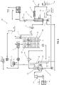
FIG. 2 shows a schematic view of an improved direct fuel cell system with a two-stage saturator. -
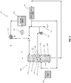
FIG. 3 shows a simplified schematic view of the direct fuel cell system ofFIG. 2 , according to an exemplary embodiment. - According to an exemplary embodiment, a fuel cell system is disclosed herein that utilizes low level heat recovered directly from a direct contact cooling tower ("DCCT"). A saturator configured to provide heated water for humidification of the reactant gases to be input into the fuel cells may be divided into two sections, and in the lower section, the fuel to the system is partially saturated using the heat from the DCCT. Hot water from the bottom of the DCCT is routed to the bottom section of the saturator. The partially-saturated fuel from the lower section of the saturator is then fully saturated to the desired level in the upper section. Hotter water is then fed to the upper section after it is preheated using heat from the system's cathode exhaust. By pre-saturating the gas in the lower section of the saturator, less heat is required in the cathode exhaust-water heat exchanger such that the heat becomes available for use for other purposes (e.g., reducing the supplemental fuel use).
- This arrangement is applicable to all Direct Fuel Cell ("DFC") designs that include water recovery, since it allows the waste heat generated by other components of the fuel cell system to be used for other purposes. For example, it is particularly useful in designs which export hydrogen, syngas, or high pressure steam from the system or in dual-stack high efficiency fuel cell systems, each of which may typically require additional heat to be applied, since much of the anode exhaust is exported, reducing the amount of heat generated in an anode gas oxidizer ("AGO") 118.
-
FIG. 1 shows afuel cell system 100 according to a first exemplary embodiment, andFIG. 2 illustrates an improved fuel cell system that includes the advantageous heat recovery system that is the subject of the present application.FIG. 1 will be described below to provide a description of the configuration and operation of the overall fuel cell system, followed by a discussion of the improved version shown inFIG. 2 . - The
fuel cell system 100 includes a fuel cell stack (i.e., fuel cell) 102 including ananode side 104 that is configured to receive fuel from afuel supply 103 and to output anode exhaust. Thefuel cell stack 102 also includes acathode side 106 that is configured to receive oxidant gas and to output cathode exhaust. Thefuel cell system 100 further includes asaturator 108 for heating and humidifying the fuel from thefuel supply 103 with water from awater recovery unit 114. A hydrocarbon-containing fuel (e.g., natural gas, propane, etc.) is supplied from thefuel supply 103. The fuel is processed in adesulfurizer 112 for removal of sulfur-containing compounds present in the fuel. Thedesulfurizer 112 includes one or more sulfur-adsorbent or sulfur-absorbent beds through which the fuel flows and which adsorb or absorb any sulfur-containing compounds in the fuel. - After passing through the
desulfurizer 112, the fuel is received by thesaturator 108, which is also configured to receive water from thewater recovery unit 114. According to an exemplary embodiment, water may be supplied to thewater recovery unit 114 from anode and/or cathode exhaust from thefuel cell stack 102, and/or from an external source (e.g., tap water). According to another exemplary embodiment, water may be provided by a start-up water polisher 132, as discussed in further detail below. - As shown in
FIG. 1 , thewater recovery unit 114 includes aDCCT 116. The DCCT 116 is configured to receive the anode exhaust and to condense at least a portion of the water in the anode exhaust. According to an exemplary embodiment, the anode exhaust may be cooled by afirst heat exchanger 115 before being received in the DCCT 116. As shown inFIG. 2 , the anode exhaust may be cooled by asecond heat exchanger 117, transferring heat from the anode exhaust to purified hydrogen, generating a heated hydrogen stream. The heated hydrogen stream may then be received in the AGO 118 and mixed (i.e., combusted) with air and fed to thecathode 106. Referring toFIG. 1 , the anode exhaust is conveyed from theanode side 104 of thefuel stack 102 to one end of theDCCT 116, while cooled recycled water is conveyed to an opposing end of theDCCT 116 from awater recycle path 123, such that the anode exhaust and the cooled recycled water flow in opposing directions relative to one another. In the DCCT 116, the anode exhaust is cooled by direct contact with the recycled water, condensing at least a portion of the water in the anode exhaust. The water condensed from the anode exhaust is mixed with the recycled water as it travels through the DCCT 116. Hot condensed water comprising a mixture of the recycled water and the water condensed from the anode exhaust is collected at the bottom of theDCCT 116. - As shown in
FIG. 1 , a first portion of the condensed water collected at the bottom of theDCCT 116 is conveyed to thewater recycle path 123, where it is cooled using a heat exchanger 124 (e.g., an airfan) for use as recycled water in theDCCT 116, while a second portion of the condensed water is output from thewater recovery unit 114 and may be sent (i.e., recycled) to thesaturator 108 for humidifying the fuel. - Cathode exhaust passes from the
cathode side 106 of thefuel cell stack 102 through a firstexhaust heat exchanger 120, configured to transfer heat from the cathode exhaust to humidified fuel (i.e., saturated gas) output from thesaturator 108 to superheat the humidified fuel. The heated humidified fuel is then fed to theanode side 104 of thefuel cell stack 102. Fuel entering theanode side 104 is reformed therein to produce hydrogen and CO and undergoes an electrochemical reaction with oxidant gas passing through thecathode side 106 to form water and CO2 as thefuel cell system 100 produces electrical power. The anode exhaust includes unreacted fuel, including hydrogen and CO, reaction products, including water vapor and CO2, and small amounts of other compounds or gases. - After heating the humidified fuel, the cathode exhaust passes through a second
exhaust heat exchanger 122, configured to transfer heat from the cathode exhaust to water from the DCCT 116. Accordingly, the secondexhaust heat exchanger 122 further pre-heats the water from theDCCT 116 and recycles the water from thesaturator 108 before the combined water is fed to thesaturator 108. According to an exemplary embodiment, the hot water is generated by the secondexhaust heat exchanger 122 transferring heat from the cathode exhaust, which in a typical situation may be heated to a temperature of about 240°F. - According to an exemplary embodiment, the water is provided to the
saturator 108 near atop portion 108a thereof and flows in a downward direction through thesaturator 108, while the fuel is provided near abottom portion 108b of thesaturator 108 and flows in an upward direction through thesaturator 108. In thesaturator 108, the fuel comes in direct contact with the water, and as a result, a first portion of the water is evaporated into the fuel, saturating the fuel with water vapor and producing humidified fuel. A second portion (i.e., the remaining portion), of the water in thesaturator 108, which is not yet evaporated into the fuel, is output from thesaturator 108 and combined with the water from theDCCT 116. The combination of unevaporated water and water from the DCCT 116 is sent through the secondexhaust heat exchanger 122 and provided to thetop portion 108a of thesaturator 108. According to an exemplary embodiment, water may be supplied from thewater recovery unit 114 to replace water in thesaturator 108 as it is evaporated to form humidified fuel and output from thesaturator 108. Excess water from thewater recovery unit 114 may be discarded from the system as blowdown water through awater blowdown stream 130. According to an exemplary embodiment, thefuel cell system 100 is configured to remove (i.e., strip out) substantially all of the CO2 in the recovered water. This process results in an increase in the pH level of the recovered water, simplifying the process of disposing of excess water from the fuel cell system 100 (e.g., the recovered water is at a pH level suitable for introduction to the environment without further processing). - Referring now to
FIGS. 2 and3 , a schematic view of afuel cell system 200 with a two-stage saturator 208 is shown. According to an exemplary embodiment, a two-stage saturator 208 includes a vessel defining a lower (i.e., first)section 209 and an upper (i.e., second)section 210, partially separated by a divider (i.e., trap pan) 211 that is configured to allow humidified fuel to pass therethrough. According to an exemplary embodiment, substantially all of the water collected at the bottom of theDCCT 116 is conveyed to thesaturator 208. According to other exemplary embodiments, only a portion of such water may be used. - As shown in
FIG. 2 , a first portion of the water is conveyed from theDCCT 116 to thelower section 209 of thesaturator 208. A second portion of the water is conveyed from theDCCT 116 to the secondexhaust heat exchanger 122 to be preheated by the cathode exhaust. The second portion of the water is then output from the secondexhaust heat exchanger 122 and routed to theupper section 210 of thesaturator 210. - According to an exemplary embodiment, the water received directly from the DCCT 116 (i.e., without first passing through the second exhaust heat exchanger 122), is provided to the
saturator 208 near atop portion 209a of thelower section 209 of thesaturator 208 and flows in a downward direction through thelower section 209, while the fuel is provided near a bottom (i.e., lower)portion 209b of thelower section 209 of thesaturator 208 and flows in an upward direction through thelower section 209. In thelower section 209 of thesaturator 208, the fuel comes in direct contact with the water, and as a result, a first portion of the water in thelower section 209 is evaporated into the fuel, saturating the fuel with water vapor and producing partially-humidified fuel. A second portion (i.e., the remaining portion), of the water in thelower section 209, which is not yet evaporated into the fuel, is output from thelower section 209 and returned to awater recycle path 223. - As shown in
FIG. 3 , the fuel is at least partially humidified in thelower section 209 and then passes through anopening 211a in the divider 211 configured to allow fuel (but not unevaporated water) to pass therethrough. For example, theopening 211a may be a hole in the divider 211 having an outer periphery defining a diameter and a surface area. According to other exemplary embodiments, theopening 211a may define other shapes. Gravity forces unevaporated water in thelower section 209 to fall downward, away from theopening 211a, whereas fuel (e.g., in gas form) and steam forming a partially-humidified fuel moves upward, passing through the opening 211. The partially-humidified fuel is output from anoutlet 212a into theupper section 210. The divider 211 defines a wall orwalls 211b extending generally upward from the outer periphery of theopening 211a. Acover 212 is disposed above theopening 211a and defines the outlet oroutlets 212a therebetween. For example, theoutlet 212a may be defined between thecover 212 and a top end of thewall 211b. According to an exemplary embodiment, thecover 212 extends beyond the outer periphery of theopening 211a (i.e., has a larger diameter and/or a larger surface area) and is configured to prevent water in theupper section 210 from passing through theopening 211a. According to another exemplary embodiment, theoutlet 212a is positioned above the divider 211 such that thecover 212 is configured to prevent water flowing downward in theupper section 210 through theoutlet 212a. For example, water may pool up on top of the divider 211 to the height of thewalls 211b before entering theoutlet 212a and flowing through theopening 211a into thelower section 209. According to another exemplary embodiment, the divider 211 includes a plurality ofopenings 211a, each configured the same as theopening 211a described above. According to another exemplary embodiment, thelower section 209 andupper section 210 may be located in separate (i.e., first and second, respectively) vessels. In this configuration, partially-humidified fuel is output from thetop portion 209a of thelower section 209 and routed between the first and second vessels to thebottom portion 210b of theupper section 210. - Referring again to
FIGS. 2 and3 , the second portion of water from theDCCT 116, which is fed through the second exhaust heat exchanger 122 (without first passing through the saturator 208), is provided to thesaturator 208 near a top (i.e., upper)portion 210a of theupper section 210 of thesaturator 208 and flows in a downward direction through theupper section 210, while the humidified fuel from thelower section 209 is provided near a bottom (i.e., lower)portion 210b of theupper section 210 of thesaturator 208 after passing through the divider 211, and flows in an upward direction through theupper section 210. The water received in thetop portion 210a of theupper section 210 of the saturator may be hotter than the water received in the top portion 109a of thelower section 209 of thesaturator 208. According to an exemplary embodiment, the second portion of water from theDCCT 116 may be fed directly to theupper section 210 of thesaturator 208. In theupper section 210 of thesaturator 208, the humidified fuel comes in direct contact with the water from the secondexhaust heat exchanger 122, and as a result, at least some of the second portion of the water in theupper section 210 is evaporated into the fuel, further saturating the fuel with water vapor and producing further-humidified fuel. Any remaining unevaporated water in theupper section 210, which is not yet evaporated into the humidified fuel, is output from theupper section 210 and may be combined with the hot water from theDCCT 116. At least a portion of the combined unevaporated water and water directly from theDCCT 116 is passed back through the secondexhaust heat exchanger 122 and provided to the top (i.e., upper)portion 209a of theupper section 209 of thesaturator 208. Any water not sent through the secondexhaust heat exchanger 122 may be removed from thefuel cell system 200 through ablowdown stream 230, described in further detail below. - By pre-saturating (i.e., pre-humidifying) the fuel in the
lower section 209 of thesaturator 208 prior to passing the water from theDCCT 116 through the secondexhaust heat exchanger 122, the partially-humidified fuel in theupper section 210 of thesaturator 208 requires less water to be further (i.e., fully) humidified. Specifically, this means that water being passed through the secondexhaust heat exchanger 122 requires less heat to be transferred from the cathode exhaust to the water in order to provide a sufficient amount of evaporated water to further (e.g., fully) humidify the fuel. Accordingly, the heat generated by the cathode exhaust may be reallocated to other locations within or outside of thefuel cell system 200. - According to an exemplary embodiment, any unevaporated water in the
upper section 210 is output from theupper section 210 of thesaturator 208 at a location above the divider 211 and below theoutlet 212a. Accordingly, the divider 211 is configured to prevent backflow of unevaporated water from theupper section 210 into thelower section 209 of thesaturator 208. According to another exemplary embodiment, water may be supplied from thewater recovery unit 114 to replace water in thesaturator 208 as it is evaporated to form humidified fuel and output from thesaturator 208. - According to an exemplary embodiment, when excess unevaporated water output from the
upper section 209 exceeds a specified amount, the excess water may be output through thewater blowdown stream 230 and removed from thefuel cell system 200. The unevaporated water is passed from thesaturator 208 to acirculation pump 228, which recycles the water to the secondexhaust heat exchanger 122. As shown inFIG. 2 , before being passed to the secondexhaust heat exchanger 122, the second portion of water may be treated using a water blowdown technique to prevent accumulation of any non-volatile contaminants or dissolved solids dissolved in the water. According to an exemplary embodiment, the amount of water removed with thewater blowdown stream 230 corresponds to the excess water condensed in theDCCT 116 above the amount needed for humidification. According to an exemplary embodiment, the excess water in thewater blowdown stream 230 may be sent off site (e.g., through a drain) or stored (e.g., in a tank) for use during start-up of thefuel cell system 200 when the water produced in thefuel cell stack 102 and condensed in thewater recovery system 214 is insufficient to humidify the fuel in thefuel cell system 200. According to another exemplary embodiment, make-up water from an external source (e.g., tap) may be used during start-up to provide at least a portion of a sufficient amount of water for humidification. - A steam-to-carbon ratio of about 1.9 may be desired for humidified fuel being introduced to the
anode 104 of thefuel cell stack 102. According to an exemplary embodiment, between 2.00 and 2.20 million BTUs of heat, and typically between 2.05 and 2.10 million BTUs, are required to achieve the ratio of 1.9. In thefuel cell system 100 with a single-stage saturator 108, most or all of the required heat must come from the cathode exhaust through the secondexhaust heat exchanger 122. In thefuel cell system 200 with a two-stage saturator 208, the water from theDCCT 116 provides around 0.8 million BTUs of heat to thelower section 209 of thesaturator 208, resulting in a steam-to-carbon ratio of about 0.8 for the partially-humidified fuel introduced to theupper section 210 of thesaturator 208. Accordingly, the partially-humidified fuel requires less heat to be transferred from the cathode exhaust to theupper section 210 in order to complete the saturation process to achieve a ratio of 1.9. According to an exemplary embodiment, the heat provided from the cathode exhaust may be reduced by over 45% relative to afuel cell system 100 having a single-stage saturator 108. - Further, in
FIG. 1 , the water output from theDCCT 116 has a high heat level from the anode exhaust. As the water passes through thewater recycle path 123, theheat exchanger 124 must be large enough to remove a sufficient amount of heat from the water before the water is reintroduced to theDCCT 116. Referring now toFIG. 2 , theheat exchanger 224 operates in a similar way to theheat exchanger 124. However, before the water output from theDCCT 116 is passed through thewater recycle path 223 and into theheat exchanger 224, it is passed through thelower section 209 of the two-stage saturator 208. The pre-saturating process in thelower section 209 transfers heat from the water to the fuel, such that the water returning from thesaturator 208 to thewater recycle path 223 is cooler, after having around 0.8 million BTUs of heat removed. Because more heat is drawn out of the water through the two-stage saturator 208 than with a single-stage saturator 108, less heat must be removed by theheat exchanger 224 before feeding the recycled water back to theDCCT 116. Accordingly, the size and/or capacity of the heat exchanger 224 (e.g., air fan) may be reduced in the embodiment shown inFIG. 2 , which may further reduce the operating and manufacturing costs of thefuel cell system 200. - As shown in
FIGS. 1 and2 , thewater recovery unit 114 may further include a start-upwater polisher recovery heat exchanger 134. Water for humidifying the fuel may first be introduced to thefuel cell system water recovery unit water polisher FIG. 1 , the start-up water may be introduced to thewater recovery unit 114 downstream from theDCCT 116 but upstream from a DCCTwater circulation pump 119 to provide water, in part, directly to thesaturator 108, without first passing through thewater recycle path 123, such that make-up water may be introduced at a lower pressure than required at an outlet of the DCCTwater circulation pump 119. As shown inFIG. 2 , the start-up water may be introduced to thewater recovery unit 214 upstream from theheat exchanger 124 andDCCT 116, such that the water passes along thewater recycle path 223 through each of theheat exchanger 124 and theDCCT 116 before being introduced to thesaturator 208. According to other exemplary embodiments, the start-up water may be introduced to thewater recovery unit fuel cell system water recovery unit fuel cell system fuel cell system blowdown stream FIGS. 1 and2 , thewater recovery unit 114 may further include a wasteheat recovery exchanger 134. The wasteheat recovery exchanger 134 may be placed anywhere along thewater recycle path water recycle path fuel cell system fuel cell system 100, 200 (e.g., when power is being produced). The blowdown of water to the tank may allow for the small amount of blowdown water to cool prior to discharge from thefuel cell system 100, 200 (e.g., to a sewer or other location). According to an exemplary embodiment, the blowdown water may be substantially pure with minor traces of electrolyte from thefuel cell stack 102. - As utilized herein, the terms "approximately," "about," "substantially," and similar terms are intended to have a broad meaning in harmony with the common and accepted usage by those of ordinary skill in the art to which the subject matter of this disclosure pertains. It should be understood by those of skill in the art who review this disclosure that these terms are intended to allow a description of certain features described and claimed without restricting the scope of these features to the precise numerical ranges provided. Accordingly, these terms should be interpreted as indicating that insubstantial or inconsequential modifications or alterations of the subject matter described and claimed are considered to be within the scope of this disclosure as recited in the appended claims.
- It should be noted that the term "exemplary" as used herein to describe various embodiments is intended to indicate that such embodiments are possible examples, representations, and/or illustrations of possible embodiments (and such term is not intended to connote that such embodiments are necessarily extraordinary or superlative examples).
- The terms "coupled," "connected," and the like as used herein mean the joining of two members directly or indirectly to one another. Such joining may be stationary (e.g., permanent) or moveable (e.g., removable or releasable). Such joining may be achieved with the two members or the two members and any additional intermediate members being integrally formed as a single unitary body with one another or with the two members or the two members and any additional intermediate members being attached to one another.
- References herein to the position of elements (e.g., "top," "bottom," "above," "below," etc.) are merely used to describe the orientation of various elements in the FIGURES. It should be noted that the orientation of various elements may differ according to other exemplary embodiments, and that such variations are intended to be encompassed by the present disclosure.
- It is to be understood that although the present invention has been described with regard to preferred embodiments thereof, various other embodiments and variants may occur to those skilled in the art, which are defined by the appended claims.
Claims (14)
- A fuel cell system comprising:a fuel cell having an anode and a cathode;a water recovery unit configured to recycle water from exhaust from the anode;a heat exchanger configured to transfer heat between exhaust from the cathode and water from the water recovery unit;a fuel source; anda saturator, comprising:a lower section defining an upper portion and a lower portion, the lower portion configured to receive fuel from the fuel source and the upper portion configured to receive water from the water recovery unit;an upper section defining an upper portion and a lower portion, the upper portion configured to receive water from the heat exchanger and the lower portion configured to receive fuel from the lower section; anda divider separating the upper section and the lower section, the divider defining an opening configured to allow fuel and steam to pass from the lower section to the upper section.
- The fuel cell system of claim 1, the divider further comprising:at least one wall extending upward from the opening;a cover disposed above the opening; andan outlet defined between the cover and the at least one wall.
- The fuel cell system of claim 1, wherein the upper section is configured to output unevaporated water from the lower portion of the upper section; and
wherein the heat exchanger is configured to receive water from at least one of the upper section and the water recovery unit. - The fuel cell system according to any one of claims 1-3, wherein the lower section is configured to at least partially humidify the fuel from the fuel source.
- The fuel cell system according to any one of claims 1-3, the divider further comprising:at least one wall extending upward from the opening;a cover disposed above the opening; andan outlet defined between the cover and the at least one wall.
- The fuel cell system according to any one of claims 1-3, the water recovery unit further comprising a direct contact cooling tower configured to condense and separate water from the exhaust from the anode;
wherein substantially all of the water in the direct contact cooling tower is output to the saturator. - The fuel cell system according to any one of claims 1-3, wherein the water recovery unit is configured to receive unevaporated water from the lower section.
- The fuel cell system according to any one of claims 1-3, wherein the heat exchanger is configured to transfer heat between the exhaust from the cathode and unevaporated water output from the upper section.
- A method of saturating fuel in a fuel cell system comprising a saturator according to any one of claims 1-8, the method comprising:providing first and second portions of water from a water recovery unit;receiving the first portion of water and fuel in the lower section of the saturator;outputting a partially-humidified fuel from the lower section;heating the second portion of water in the heat exchanger;receiving the second portion of water and the partially-humidified fuel in the upper section of the saturator; andoutputting a further humidified fuel from the upper section.
- The method of claim 9, wherein the fuel received in the lower portion of the lower section is humidified by the first portion of water, generating the partially-humidified fuel.
- The method of claim 9, further comprising outputting unevaporated water from the upper section; and
heating the unevaporated water in the heat exchanger. - The method of claim 11, further comprising removing, through a blowdown stream, at least a portion of the unevaporated water from the upper section.
- The method of claim 9, further comprising outputting unevaporated water from the lower section; and
receiving the unevaporated water in the water recovery unit. - The method of claim 9, wherein substantially all of the water in the water recovery unit is received in the saturator.
Applications Claiming Priority (2)
| Application Number | Priority Date | Filing Date | Title |
|---|---|---|---|
| US15/252,338 US10541434B2 (en) | 2016-08-31 | 2016-08-31 | Heat recovery for saturator water recovery of a direct fuel cell system |
| PCT/US2017/047528 WO2018044589A1 (en) | 2016-08-31 | 2017-08-18 | Saturator employing heat and water recovery of a fuel cell system |
Publications (2)
| Publication Number | Publication Date |
|---|---|
| EP3507848A1 EP3507848A1 (en) | 2019-07-10 |
| EP3507848B1 true EP3507848B1 (en) | 2022-12-07 |
Family
ID=59714175
Family Applications (1)
| Application Number | Title | Priority Date | Filing Date |
|---|---|---|---|
| EP17758397.8A Active EP3507848B1 (en) | 2016-08-31 | 2017-08-18 | Saturator employing heat and water recovery of a fuel cell system |
Country Status (7)
| Country | Link |
|---|---|
| US (1) | US10541434B2 (en) |
| EP (1) | EP3507848B1 (en) |
| JP (1) | JP6970740B2 (en) |
| KR (1) | KR102182267B1 (en) |
| CN (1) | CN109690853B (en) |
| CA (1) | CA3035606C (en) |
| WO (1) | WO2018044589A1 (en) |
Families Citing this family (7)
| Publication number | Priority date | Publication date | Assignee | Title |
|---|---|---|---|---|
| DE102015222635A1 (en) * | 2015-11-17 | 2017-05-18 | Volkswagen Ag | Fuel cell system and method for recycling water in a fuel cell system |
| KR101838510B1 (en) * | 2016-03-11 | 2018-03-14 | 현대자동차주식회사 | Evaporative cooling type fuel cell system and stack colling control method for the same |
| US10546724B2 (en) * | 2017-05-10 | 2020-01-28 | Mks Instruments, Inc. | Pulsed, bidirectional radio frequency source/load |
| DK3869599T3 (en) * | 2019-03-25 | 2025-01-02 | Korea Inst Mach & Materials | Reversible water electrolysis system and method for operating the same |
| CN113126673A (en) * | 2019-12-31 | 2021-07-16 | 苏州注雾科技有限公司 | Large-temperature-range humidity adjusting system with return water compensation loop |
| JP7222023B2 (en) * | 2020-05-26 | 2023-02-14 | インディアン オイル コーポレイション リミテッド | Method and apparatus for operating PEM fuel cells with CO-contaminated hydrogen gas |
| CN114413503B (en) * | 2022-01-19 | 2022-10-25 | 西安交通大学 | Renewable energy driven zero-carbon efficient distributed energy supply system and operation method |
Family Cites Families (9)
| Publication number | Priority date | Publication date | Assignee | Title |
|---|---|---|---|---|
| US3292998A (en) * | 1960-01-11 | 1966-12-20 | Chemical Construction Corp | Method of producing hydrogen from a carbon monoxide-containing gas stream and heat recovery |
| GB2001336B (en) | 1977-06-27 | 1982-02-10 | Giammarco P | Process for the production of hydrogen |
| US6694744B1 (en) | 2000-11-09 | 2004-02-24 | General Electric Company | Fuel gas moisturization system level control |
| US7858256B2 (en) * | 2005-05-09 | 2010-12-28 | Bloom Energy Corporation | High temperature fuel cell system with integrated heat exchanger network |
| US7862938B2 (en) | 2007-02-05 | 2011-01-04 | Fuelcell Energy, Inc. | Integrated fuel cell and heat engine hybrid system for high efficiency power generation |
| US8367256B2 (en) * | 2008-01-09 | 2013-02-05 | Fuelcell Energy, Inc. | Water recovery assembly for use in high temperature fuel cell systems |
| US8062799B2 (en) | 2008-08-19 | 2011-11-22 | Fuelcell Energy, Inc. | High-efficiency dual-stack molten carbonate fuel cell system |
| JP2010112626A (en) * | 2008-11-06 | 2010-05-20 | Toyota Motor Corp | Humidifier, fuel cell evaluation device, and fuel cell system |
| US8445147B2 (en) * | 2009-02-26 | 2013-05-21 | Fuelcell Energy, Inc. | Fuel humidifier assembly for use in high temperature fuel cell systems |
-
2016
- 2016-08-31 US US15/252,338 patent/US10541434B2/en active Active
-
2017
- 2017-08-18 EP EP17758397.8A patent/EP3507848B1/en active Active
- 2017-08-18 CN CN201780055125.6A patent/CN109690853B/en active Active
- 2017-08-18 CA CA3035606A patent/CA3035606C/en active Active
- 2017-08-18 WO PCT/US2017/047528 patent/WO2018044589A1/en not_active Ceased
- 2017-08-18 KR KR1020197008388A patent/KR102182267B1/en active Active
- 2017-08-18 JP JP2019511765A patent/JP6970740B2/en active Active
Also Published As
| Publication number | Publication date |
|---|---|
| CN109690853B (en) | 2022-07-05 |
| US10541434B2 (en) | 2020-01-21 |
| CN109690853A (en) | 2019-04-26 |
| CA3035606C (en) | 2023-02-14 |
| CA3035606A1 (en) | 2018-03-08 |
| JP2019526902A (en) | 2019-09-19 |
| KR20190043154A (en) | 2019-04-25 |
| EP3507848A1 (en) | 2019-07-10 |
| KR102182267B1 (en) | 2020-11-25 |
| JP6970740B2 (en) | 2021-11-24 |
| WO2018044589A1 (en) | 2018-03-08 |
| US20180062186A1 (en) | 2018-03-01 |
Similar Documents
| Publication | Publication Date | Title |
|---|---|---|
| EP3507848B1 (en) | Saturator employing heat and water recovery of a fuel cell system | |
| EP2240977B1 (en) | Water recovery assembly for use in high temperature fuel cell systems | |
| US6316134B1 (en) | Fuel cell electric power generation system | |
| US7507487B2 (en) | Solid polymer fuel cell with reactant air humidified by a processed water tank | |
| EP0467051A1 (en) | LNG cryogenic power generation system using molten carbonate fuel cells | |
| EP2401784B1 (en) | Fuel humidifier assembly for use in high temperature fuel cell systems | |
| US8227119B2 (en) | Fuel cell system | |
| KR20230070163A (en) | Electrolyzer system with steam generation and method of operating same | |
| JP4592265B2 (en) | Fuel cell system | |
| US6787255B2 (en) | Fuel cell power generating system and operation method | |
| US6558826B1 (en) | Fuel cell system fluid recovery | |
| US11541350B2 (en) | Heat recovery from an electrochemical hydrogen separation system | |
| JP2013155051A (en) | Reforming apparatus | |
| JP2012115784A (en) | Water treatment system, and fuel cell electric power system using the same | |
| JP7224191B2 (en) | power generation system | |
| JP2012155979A (en) | Fuel cell system | |
| EP4556454A1 (en) | Methane synthesis system | |
| JP2009123445A (en) | Circulation water treatment device of fuel cell power generating device | |
| KR20120133634A (en) | Fuel cell system and ship having the same |
Legal Events
| Date | Code | Title | Description |
|---|---|---|---|
| STAA | Information on the status of an ep patent application or granted ep patent |
Free format text: STATUS: UNKNOWN |
|
| STAA | Information on the status of an ep patent application or granted ep patent |
Free format text: STATUS: THE INTERNATIONAL PUBLICATION HAS BEEN MADE |
|
| PUAI | Public reference made under article 153(3) epc to a published international application that has entered the european phase |
Free format text: ORIGINAL CODE: 0009012 |
|
| STAA | Information on the status of an ep patent application or granted ep patent |
Free format text: STATUS: REQUEST FOR EXAMINATION WAS MADE |
|
| 17P | Request for examination filed |
Effective date: 20190325 |
|
| AK | Designated contracting states |
Kind code of ref document: A1 Designated state(s): AL AT BE BG CH CY CZ DE DK EE ES FI FR GB GR HR HU IE IS IT LI LT LU LV MC MK MT NL NO PL PT RO RS SE SI SK SM TR |
|
| AX | Request for extension of the european patent |
Extension state: BA ME |
|
| DAV | Request for validation of the european patent (deleted) | ||
| DAX | Request for extension of the european patent (deleted) | ||
| REG | Reference to a national code |
Ref country code: DE Ref legal event code: R079 Ref document number: 602017064382 Country of ref document: DE Free format text: PREVIOUS MAIN CLASS: H01M0008063700 Ipc: H01M0008120000 |
|
| GRAP | Despatch of communication of intention to grant a patent |
Free format text: ORIGINAL CODE: EPIDOSNIGR1 |
|
| STAA | Information on the status of an ep patent application or granted ep patent |
Free format text: STATUS: GRANT OF PATENT IS INTENDED |
|
| RIC1 | Information provided on ipc code assigned before grant |
Ipc: F01K 21/04 20060101ALI20220321BHEP Ipc: F22B 1/18 20060101ALI20220321BHEP Ipc: B01B 1/00 20060101ALI20220321BHEP Ipc: F25B 39/00 20060101ALI20220321BHEP Ipc: F28B 9/08 20060101ALI20220321BHEP Ipc: H01M 8/04119 20160101ALI20220321BHEP Ipc: H01M 8/04291 20160101ALI20220321BHEP Ipc: H01M 8/14 20060101ALI20220321BHEP Ipc: H01M 8/04014 20160101ALI20220321BHEP Ipc: H01M 8/0637 20160101ALI20220321BHEP Ipc: H01M 8/12 20160101AFI20220321BHEP |
|
| GRAJ | Information related to disapproval of communication of intention to grant by the applicant or resumption of examination proceedings by the epo deleted |
Free format text: ORIGINAL CODE: EPIDOSDIGR1 |
|
| STAA | Information on the status of an ep patent application or granted ep patent |
Free format text: STATUS: REQUEST FOR EXAMINATION WAS MADE |
|
| INTG | Intention to grant announced |
Effective date: 20220414 |
|
| INTC | Intention to grant announced (deleted) | ||
| GRAP | Despatch of communication of intention to grant a patent |
Free format text: ORIGINAL CODE: EPIDOSNIGR1 |
|
| STAA | Information on the status of an ep patent application or granted ep patent |
Free format text: STATUS: GRANT OF PATENT IS INTENDED |
|
| INTG | Intention to grant announced |
Effective date: 20220627 |
|
| GRAS | Grant fee paid |
Free format text: ORIGINAL CODE: EPIDOSNIGR3 |
|
| GRAA | (expected) grant |
Free format text: ORIGINAL CODE: 0009210 |
|
| STAA | Information on the status of an ep patent application or granted ep patent |
Free format text: STATUS: THE PATENT HAS BEEN GRANTED |
|
| AK | Designated contracting states |
Kind code of ref document: B1 Designated state(s): AL AT BE BG CH CY CZ DE DK EE ES FI FR GB GR HR HU IE IS IT LI LT LU LV MC MK MT NL NO PL PT RO RS SE SI SK SM TR |
|
| REG | Reference to a national code |
Ref country code: GB Ref legal event code: FG4D |
|
| REG | Reference to a national code |
Ref country code: CH Ref legal event code: EP Ref country code: AT Ref legal event code: REF Ref document number: 1536830 Country of ref document: AT Kind code of ref document: T Effective date: 20221215 |
|
| REG | Reference to a national code |
Ref country code: DE Ref legal event code: R096 Ref document number: 602017064382 Country of ref document: DE |
|
| REG | Reference to a national code |
Ref country code: IE Ref legal event code: FG4D |
|
| REG | Reference to a national code |
Ref country code: LT Ref legal event code: MG9D |
|
| REG | Reference to a national code |
Ref country code: NL Ref legal event code: MP Effective date: 20221207 |
|
| PG25 | Lapsed in a contracting state [announced via postgrant information from national office to epo] |
Ref country code: SE Free format text: LAPSE BECAUSE OF FAILURE TO SUBMIT A TRANSLATION OF THE DESCRIPTION OR TO PAY THE FEE WITHIN THE PRESCRIBED TIME-LIMIT Effective date: 20221207 Ref country code: NO Free format text: LAPSE BECAUSE OF FAILURE TO SUBMIT A TRANSLATION OF THE DESCRIPTION OR TO PAY THE FEE WITHIN THE PRESCRIBED TIME-LIMIT Effective date: 20230307 Ref country code: LT Free format text: LAPSE BECAUSE OF FAILURE TO SUBMIT A TRANSLATION OF THE DESCRIPTION OR TO PAY THE FEE WITHIN THE PRESCRIBED TIME-LIMIT Effective date: 20221207 Ref country code: FI Free format text: LAPSE BECAUSE OF FAILURE TO SUBMIT A TRANSLATION OF THE DESCRIPTION OR TO PAY THE FEE WITHIN THE PRESCRIBED TIME-LIMIT Effective date: 20221207 Ref country code: ES Free format text: LAPSE BECAUSE OF FAILURE TO SUBMIT A TRANSLATION OF THE DESCRIPTION OR TO PAY THE FEE WITHIN THE PRESCRIBED TIME-LIMIT Effective date: 20221207 |
|
| REG | Reference to a national code |
Ref country code: AT Ref legal event code: MK05 Ref document number: 1536830 Country of ref document: AT Kind code of ref document: T Effective date: 20221207 |
|
| PG25 | Lapsed in a contracting state [announced via postgrant information from national office to epo] |
Ref country code: RS Free format text: LAPSE BECAUSE OF FAILURE TO SUBMIT A TRANSLATION OF THE DESCRIPTION OR TO PAY THE FEE WITHIN THE PRESCRIBED TIME-LIMIT Effective date: 20221207 Ref country code: PL Free format text: LAPSE BECAUSE OF FAILURE TO SUBMIT A TRANSLATION OF THE DESCRIPTION OR TO PAY THE FEE WITHIN THE PRESCRIBED TIME-LIMIT Effective date: 20221207 Ref country code: LV Free format text: LAPSE BECAUSE OF FAILURE TO SUBMIT A TRANSLATION OF THE DESCRIPTION OR TO PAY THE FEE WITHIN THE PRESCRIBED TIME-LIMIT Effective date: 20221207 Ref country code: HR Free format text: LAPSE BECAUSE OF FAILURE TO SUBMIT A TRANSLATION OF THE DESCRIPTION OR TO PAY THE FEE WITHIN THE PRESCRIBED TIME-LIMIT Effective date: 20221207 Ref country code: GR Free format text: LAPSE BECAUSE OF FAILURE TO SUBMIT A TRANSLATION OF THE DESCRIPTION OR TO PAY THE FEE WITHIN THE PRESCRIBED TIME-LIMIT Effective date: 20230308 |
|
| P01 | Opt-out of the competence of the unified patent court (upc) registered |
Effective date: 20230508 |
|
| PG25 | Lapsed in a contracting state [announced via postgrant information from national office to epo] |
Ref country code: NL Free format text: LAPSE BECAUSE OF FAILURE TO SUBMIT A TRANSLATION OF THE DESCRIPTION OR TO PAY THE FEE WITHIN THE PRESCRIBED TIME-LIMIT Effective date: 20221207 |
|
| PG25 | Lapsed in a contracting state [announced via postgrant information from national office to epo] |
Ref country code: SM Free format text: LAPSE BECAUSE OF FAILURE TO SUBMIT A TRANSLATION OF THE DESCRIPTION OR TO PAY THE FEE WITHIN THE PRESCRIBED TIME-LIMIT Effective date: 20221207 Ref country code: RO Free format text: LAPSE BECAUSE OF FAILURE TO SUBMIT A TRANSLATION OF THE DESCRIPTION OR TO PAY THE FEE WITHIN THE PRESCRIBED TIME-LIMIT Effective date: 20221207 Ref country code: PT Free format text: LAPSE BECAUSE OF FAILURE TO SUBMIT A TRANSLATION OF THE DESCRIPTION OR TO PAY THE FEE WITHIN THE PRESCRIBED TIME-LIMIT Effective date: 20230410 Ref country code: EE Free format text: LAPSE BECAUSE OF FAILURE TO SUBMIT A TRANSLATION OF THE DESCRIPTION OR TO PAY THE FEE WITHIN THE PRESCRIBED TIME-LIMIT Effective date: 20221207 Ref country code: CZ Free format text: LAPSE BECAUSE OF FAILURE TO SUBMIT A TRANSLATION OF THE DESCRIPTION OR TO PAY THE FEE WITHIN THE PRESCRIBED TIME-LIMIT Effective date: 20221207 Ref country code: AT Free format text: LAPSE BECAUSE OF FAILURE TO SUBMIT A TRANSLATION OF THE DESCRIPTION OR TO PAY THE FEE WITHIN THE PRESCRIBED TIME-LIMIT Effective date: 20221207 |
|
| PG25 | Lapsed in a contracting state [announced via postgrant information from national office to epo] |
Ref country code: SK Free format text: LAPSE BECAUSE OF FAILURE TO SUBMIT A TRANSLATION OF THE DESCRIPTION OR TO PAY THE FEE WITHIN THE PRESCRIBED TIME-LIMIT Effective date: 20221207 Ref country code: IS Free format text: LAPSE BECAUSE OF FAILURE TO SUBMIT A TRANSLATION OF THE DESCRIPTION OR TO PAY THE FEE WITHIN THE PRESCRIBED TIME-LIMIT Effective date: 20230407 Ref country code: AL Free format text: LAPSE BECAUSE OF FAILURE TO SUBMIT A TRANSLATION OF THE DESCRIPTION OR TO PAY THE FEE WITHIN THE PRESCRIBED TIME-LIMIT Effective date: 20221207 |
|
| REG | Reference to a national code |
Ref country code: DE Ref legal event code: R097 Ref document number: 602017064382 Country of ref document: DE |
|
| PLBE | No opposition filed within time limit |
Free format text: ORIGINAL CODE: 0009261 |
|
| STAA | Information on the status of an ep patent application or granted ep patent |
Free format text: STATUS: NO OPPOSITION FILED WITHIN TIME LIMIT |
|
| PG25 | Lapsed in a contracting state [announced via postgrant information from national office to epo] |
Ref country code: DK Free format text: LAPSE BECAUSE OF FAILURE TO SUBMIT A TRANSLATION OF THE DESCRIPTION OR TO PAY THE FEE WITHIN THE PRESCRIBED TIME-LIMIT Effective date: 20221207 |
|
| 26N | No opposition filed |
Effective date: 20230908 |
|
| PG25 | Lapsed in a contracting state [announced via postgrant information from national office to epo] |
Ref country code: SI Free format text: LAPSE BECAUSE OF FAILURE TO SUBMIT A TRANSLATION OF THE DESCRIPTION OR TO PAY THE FEE WITHIN THE PRESCRIBED TIME-LIMIT Effective date: 20221207 |
|
| PG25 | Lapsed in a contracting state [announced via postgrant information from national office to epo] |
Ref country code: MC Free format text: LAPSE BECAUSE OF FAILURE TO SUBMIT A TRANSLATION OF THE DESCRIPTION OR TO PAY THE FEE WITHIN THE PRESCRIBED TIME-LIMIT Effective date: 20221207 |
|
| REG | Reference to a national code |
Ref country code: CH Ref legal event code: PL |
|
| PG25 | Lapsed in a contracting state [announced via postgrant information from national office to epo] |
Ref country code: MC Free format text: LAPSE BECAUSE OF FAILURE TO SUBMIT A TRANSLATION OF THE DESCRIPTION OR TO PAY THE FEE WITHIN THE PRESCRIBED TIME-LIMIT Effective date: 20221207 |
|
| PG25 | Lapsed in a contracting state [announced via postgrant information from national office to epo] |
Ref country code: LU Free format text: LAPSE BECAUSE OF NON-PAYMENT OF DUE FEES Effective date: 20230818 |
|
| PG25 | Lapsed in a contracting state [announced via postgrant information from national office to epo] |
Ref country code: LU Free format text: LAPSE BECAUSE OF NON-PAYMENT OF DUE FEES Effective date: 20230818 Ref country code: CH Free format text: LAPSE BECAUSE OF NON-PAYMENT OF DUE FEES Effective date: 20230831 |
|
| REG | Reference to a national code |
Ref country code: BE Ref legal event code: MM Effective date: 20230831 |
|
| REG | Reference to a national code |
Ref country code: IE Ref legal event code: MM4A |
|
| PG25 | Lapsed in a contracting state [announced via postgrant information from national office to epo] |
Ref country code: IE Free format text: LAPSE BECAUSE OF NON-PAYMENT OF DUE FEES Effective date: 20230818 |
|
| PG25 | Lapsed in a contracting state [announced via postgrant information from national office to epo] |
Ref country code: IE Free format text: LAPSE BECAUSE OF NON-PAYMENT OF DUE FEES Effective date: 20230818 Ref country code: FR Free format text: LAPSE BECAUSE OF NON-PAYMENT OF DUE FEES Effective date: 20230831 |
|
| PG25 | Lapsed in a contracting state [announced via postgrant information from national office to epo] |
Ref country code: BE Free format text: LAPSE BECAUSE OF NON-PAYMENT OF DUE FEES Effective date: 20230831 |
|
| PG25 | Lapsed in a contracting state [announced via postgrant information from national office to epo] |
Ref country code: BG Free format text: LAPSE BECAUSE OF FAILURE TO SUBMIT A TRANSLATION OF THE DESCRIPTION OR TO PAY THE FEE WITHIN THE PRESCRIBED TIME-LIMIT Effective date: 20221207 |
|
| PG25 | Lapsed in a contracting state [announced via postgrant information from national office to epo] |
Ref country code: BG Free format text: LAPSE BECAUSE OF FAILURE TO SUBMIT A TRANSLATION OF THE DESCRIPTION OR TO PAY THE FEE WITHIN THE PRESCRIBED TIME-LIMIT Effective date: 20221207 |
|
| PG25 | Lapsed in a contracting state [announced via postgrant information from national office to epo] |
Ref country code: CY Free format text: LAPSE BECAUSE OF FAILURE TO SUBMIT A TRANSLATION OF THE DESCRIPTION OR TO PAY THE FEE WITHIN THE PRESCRIBED TIME-LIMIT; INVALID AB INITIO Effective date: 20170818 |
|
| PG25 | Lapsed in a contracting state [announced via postgrant information from national office to epo] |
Ref country code: HU Free format text: LAPSE BECAUSE OF FAILURE TO SUBMIT A TRANSLATION OF THE DESCRIPTION OR TO PAY THE FEE WITHIN THE PRESCRIBED TIME-LIMIT; INVALID AB INITIO Effective date: 20170818 |
|
| PGFP | Annual fee paid to national office [announced via postgrant information from national office to epo] |
Ref country code: DE Payment date: 20250724 Year of fee payment: 9 |
|
| PGFP | Annual fee paid to national office [announced via postgrant information from national office to epo] |
Ref country code: IT Payment date: 20250723 Year of fee payment: 9 |
|
| PGFP | Annual fee paid to national office [announced via postgrant information from national office to epo] |
Ref country code: GB Payment date: 20250725 Year of fee payment: 9 |
|
| PG25 | Lapsed in a contracting state [announced via postgrant information from national office to epo] |
Ref country code: TR Free format text: LAPSE BECAUSE OF FAILURE TO SUBMIT A TRANSLATION OF THE DESCRIPTION OR TO PAY THE FEE WITHIN THE PRESCRIBED TIME-LIMIT Effective date: 20221207 |