EP3507667B1 - Apparatus and method for retaining a noise attenuation assembly for use with a pressure regulator - Google Patents
Apparatus and method for retaining a noise attenuation assembly for use with a pressure regulator Download PDFInfo
- Publication number
- EP3507667B1 EP3507667B1 EP17764712.0A EP17764712A EP3507667B1 EP 3507667 B1 EP3507667 B1 EP 3507667B1 EP 17764712 A EP17764712 A EP 17764712A EP 3507667 B1 EP3507667 B1 EP 3507667B1
- Authority
- EP
- European Patent Office
- Prior art keywords
- plate
- disposed
- rods
- outer edge
- rod
- Prior art date
- Legal status (The legal status is an assumption and is not a legal conclusion. Google has not performed a legal analysis and makes no representation as to the accuracy of the status listed.)
- Active
Links
Images




Classifications
-
- F—MECHANICAL ENGINEERING; LIGHTING; HEATING; WEAPONS; BLASTING
- F16—ENGINEERING ELEMENTS AND UNITS; GENERAL MEASURES FOR PRODUCING AND MAINTAINING EFFECTIVE FUNCTIONING OF MACHINES OR INSTALLATIONS; THERMAL INSULATION IN GENERAL
- F16K—VALVES; TAPS; COCKS; ACTUATING-FLOATS; DEVICES FOR VENTING OR AERATING
- F16K47/00—Means in valves for absorbing fluid energy
- F16K47/02—Means in valves for absorbing fluid energy for preventing water-hammer or noise
-
- F—MECHANICAL ENGINEERING; LIGHTING; HEATING; WEAPONS; BLASTING
- F16—ENGINEERING ELEMENTS AND UNITS; GENERAL MEASURES FOR PRODUCING AND MAINTAINING EFFECTIVE FUNCTIONING OF MACHINES OR INSTALLATIONS; THERMAL INSULATION IN GENERAL
- F16K—VALVES; TAPS; COCKS; ACTUATING-FLOATS; DEVICES FOR VENTING OR AERATING
- F16K47/00—Means in valves for absorbing fluid energy
- F16K47/08—Means in valves for absorbing fluid energy for decreasing pressure or noise level and having a throttling member separate from the closure member, e.g. screens, slots, labyrinths
-
- F—MECHANICAL ENGINEERING; LIGHTING; HEATING; WEAPONS; BLASTING
- F16—ENGINEERING ELEMENTS AND UNITS; GENERAL MEASURES FOR PRODUCING AND MAINTAINING EFFECTIVE FUNCTIONING OF MACHINES OR INSTALLATIONS; THERMAL INSULATION IN GENERAL
- F16K—VALVES; TAPS; COCKS; ACTUATING-FLOATS; DEVICES FOR VENTING OR AERATING
- F16K1/00—Lift valves or globe valves, i.e. cut-off apparatus with closure members having at least a component of their opening and closing motion perpendicular to the closing faces
- F16K1/12—Lift valves or globe valves, i.e. cut-off apparatus with closure members having at least a component of their opening and closing motion perpendicular to the closing faces with streamlined valve member around which the fluid flows when the valve is opened
- F16K1/123—Lift valves or globe valves, i.e. cut-off apparatus with closure members having at least a component of their opening and closing motion perpendicular to the closing faces with streamlined valve member around which the fluid flows when the valve is opened with stationary valve member and moving sleeve
-
- F—MECHANICAL ENGINEERING; LIGHTING; HEATING; WEAPONS; BLASTING
- F16—ENGINEERING ELEMENTS AND UNITS; GENERAL MEASURES FOR PRODUCING AND MAINTAINING EFFECTIVE FUNCTIONING OF MACHINES OR INSTALLATIONS; THERMAL INSULATION IN GENERAL
- F16K—VALVES; TAPS; COCKS; ACTUATING-FLOATS; DEVICES FOR VENTING OR AERATING
- F16K31/00—Actuating devices; Operating means; Releasing devices
- F16K31/12—Actuating devices; Operating means; Releasing devices actuated by fluid
- F16K31/126—Actuating devices; Operating means; Releasing devices actuated by fluid the fluid acting on a diaphragm, bellows, or the like
- F16K31/1262—Actuating devices; Operating means; Releasing devices actuated by fluid the fluid acting on a diaphragm, bellows, or the like one side of the diaphragm being spring loaded
-
- F—MECHANICAL ENGINEERING; LIGHTING; HEATING; WEAPONS; BLASTING
- F16—ENGINEERING ELEMENTS AND UNITS; GENERAL MEASURES FOR PRODUCING AND MAINTAINING EFFECTIVE FUNCTIONING OF MACHINES OR INSTALLATIONS; THERMAL INSULATION IN GENERAL
- F16K—VALVES; TAPS; COCKS; ACTUATING-FLOATS; DEVICES FOR VENTING OR AERATING
- F16K51/00—Other details not peculiar to particular types of valves or cut-off apparatus
-
- F—MECHANICAL ENGINEERING; LIGHTING; HEATING; WEAPONS; BLASTING
- F16—ENGINEERING ELEMENTS AND UNITS; GENERAL MEASURES FOR PRODUCING AND MAINTAINING EFFECTIVE FUNCTIONING OF MACHINES OR INSTALLATIONS; THERMAL INSULATION IN GENERAL
- F16L—PIPES; JOINTS OR FITTINGS FOR PIPES; SUPPORTS FOR PIPES, CABLES OR PROTECTIVE TUBING; MEANS FOR THERMAL INSULATION IN GENERAL
- F16L55/00—Devices or appurtenances for use in, or in connection with, pipes or pipe systems
- F16L55/02—Energy absorbers; Noise absorbers
- F16L55/027—Throttle passages
- F16L55/02709—Throttle passages in the form of perforated plates
- F16L55/02718—Throttle passages in the form of perforated plates placed transversely
-
- G—PHYSICS
- G05—CONTROLLING; REGULATING
- G05D—SYSTEMS FOR CONTROLLING OR REGULATING NON-ELECTRIC VARIABLES
- G05D16/00—Control of fluid pressure
- G05D16/04—Control of fluid pressure without auxiliary power
- G05D16/06—Control of fluid pressure without auxiliary power the sensing element being a flexible membrane, yielding to pressure, e.g. diaphragm, bellows, capsule
- G05D16/063—Control of fluid pressure without auxiliary power the sensing element being a flexible membrane, yielding to pressure, e.g. diaphragm, bellows, capsule the sensing element being a membrane
- G05D16/0644—Control of fluid pressure without auxiliary power the sensing element being a flexible membrane, yielding to pressure, e.g. diaphragm, bellows, capsule the sensing element being a membrane the membrane acting directly on the obturator
- G05D16/0655—Control of fluid pressure without auxiliary power the sensing element being a flexible membrane, yielding to pressure, e.g. diaphragm, bellows, capsule the sensing element being a membrane the membrane acting directly on the obturator using one spring-loaded membrane
Definitions
- the present disclosure relates to gas regulators, and more particularly, to an apparatus and method for retaining a noise attenuation device for use with a pressure regulator.
- the pressure at which typical gas distribution systems supply gas may vary according to the demands placed on the system, the climate, the source of supply, and/or other factors.
- most end-user facilities equipped with gas appliances such as furnaces, ovens, etc., require the gas to be delivered in accordance with a predetermined pressure, and at or below a maximum capacity of a gas regulator. Therefore, gas regulators are implemented into these distribution systems to ensure that the delivered gas meets the requirements of the end-user facilities.
- a conventional apparatus 10 for retaining a noise attenuation device 12 coupled to a fluid regulating device 13 includes a single rod 14 disposed within a center 16 of noise attenuation plates 18.
- the rod 14 supports the plates 18 within a body 20 of the noise attenuation device 12.
- Springs are typically enclosed within a cage 22, such as a cylindrical cage, disposed within the body 20 near a front portion 24 of the noise attenuation device 12.
- the springs redirect the flow of gas or fluid flowing through the cage 22 and the plates 18 to reduce fluid pressure flowing through an outlet 26 ( Figure 1 ) of a regulator and reduce the noise associated with the same.
- Another known attenuation device is described for example in the document US-A-2014/0069737 .
- Document US-A-2012/0006615 discloses a high pressure drop muffling system.
- a throttle device for low-noise expansion of a gas flow in a pipeline is also described in the document DE-B-1261712 .
- the high force of the outlet pressure causes one or both of the cage 22 and plates 18 to bend. This interferes with, if not destroys, the function of the noise attenuation device 12. More specifically, and in one example, the force of the fluid pressure causes the plates 18 to detach from an inside surface of the body 20 of the noise attenuation device 12 and fold over within the body 20. As a result, the regulator noise is unable to be reduced or suppressed, and the noise attenuation device 12 fails to function properly.
- a fluid regulating device in accordance with a first exemplary aspect, includes a valve comprising an inlet, an outlet, and a valve seat disposed between the inlet and the outlet for allowing fluid to flow through the valve.
- An actuator is coupled to the valve and includes a control assembly having a control element and a diaphragm operably connected to the control element.
- the control element is disposed within the valve and adapted to be displaced relative to the valve seat for controlling the flow of a fluid between the inlet and the outlet.
- a noise attenuation assembly is coupled to the outlet and includes a cylindrical body and at least one plate disposed within the cylindrical body, the at least one plate having an outer edge.
- An apparatus for retaining the noise attenuation assembly includes a plurality of rods coupled to the at least one plate.
- the plurality of rods includes at least one rod having a first end disposed through the outer edge of the at least one plate.
- an apparatus for retaining a noise attenuation assembly for use with a fluid regulating device includes an inlet and an outlet, and the noise attenuation assembly is coupled to the outlet and includes a front plate, a middle plate, and a rear plate disposed within the cylindrical body. Each of the front, middle and rear plates has an outer edge.
- the apparatus for retaining the noise attenuation assembly includes a plurality of rods. The plurality of rods have at least one rod. In addition, the at least one rod is disposed in the outer edge of one or more of the front plate, the middle plate, and the rear plate.
- a method for retaining a noise attenuation assembly for use with a fluid regulating device includes providing a plurality of rods. The method further includes disposing at least one rod of the plurality of rods within in an outer edge of one or more of a front plate, a middle plate or a rear plate of the noise attenuation assembly to distribute stress during operation of the fluid regulating valve toward the outer edges of the plates.
- a fluid regulating device may optionally include any one or more of the following further preferred forms.
- the noise attenuation assembly includes three plates, the three plates including a front plate, a middle plate, and a rear plate.
- Each of the front, middle and rear plates has an outer edge and an outer surface, and the outer surface of each plate contacts an inner surface of a cylindrical body.
- the at least one rod of the plurality of rods may have a front end, a middle portion, and a rear end, with the front end disposed in the outer edge of the front plate, the middle portion disposed in the outer edge of the middle plate, and the rear end disposed in the outer edge of the rear plate.
- the plurality of rods may include six rods, each rod having a front end, a middle portion, and a rear end. Each front end is disposed within the outer edge of the front plate, each middle portion disposed within the outer edge of the middle plate, and each rear end disposed within the outer edge of the rear plate. So configured, the six rods are equidistantly disposed around each outer edge of the front plate, the middle plate, and the rear plate of the noise attenuation assembly, distributing stress towards the outer edges.
- the plurality of rods may include six rods disposed in each of the front, middle and rear plates around the outer edges of each of the front, middle, and rear plates.
- a nut may secure each rod of the plurality of rods to the outer edges of each of the front, middle, and rear plates.
- the apparatus for retaining the at least one plate may further include a front support member coupled to a front surface of the front plate and through which the at least one rod of the plurality of rods is disposed and secured.
- the front support member may be secured to the front plate by one or more nuts or bolts.
- the apparatus may include a rear support member coupled to a rear surface of the rear plate and through which the at least one rod of the plurality of rods is disposed and secured.
- the rear support member may be secured to the rear plate by one or more nuts or bolts.
- the front support member may include a ring having a rear surface in contact with the outer edge of the front plate.
- the noise attenuation assembly may further include three additional plates disposed between the front plate and the middle plate. Each of the three additional plates may include an outer edge, wherein the at least one rod is disposed in the outer edge of each of the front, middle, and rear plates and the three additional plates disposed between the front plate and the middle plate
- the method may further include securing the at least one rod of the plurality of rods disposed in the outer edge of one or more of the front, middle or rear plates of the noise attenuation assembly via a nut.
- disposing the at least one rod of the plurality of rods in the outer edge of one or more of the front, middle, or rear plates may include disposing six rods of the plurality of rods in one or more of: (1) the outer edges of each of the front, middle, and rear plates; or (2) the outer edges of each of the front, middle, and rear plates and an outer edge of each of three additional plates disposed between the front plate and the middle plate.
- disposing the at least one rod of the plurality of rods in an outer edge of one or more of the front, middle, or rear plates may include disposing a front end of each rod in the front plate, disposing a corresponding middle portion of each rod in the middle plate, and disposing a corresponding rear end of each rod in the rear plate.
- the method may further include coupling a front support member to a front surface of the front plate, wherein a front end of at least one rod of the plurality of rods is disposed in the front support member.
- the method may also include coupling a rear support member to a rear surface of the rear plate, wherein a rear end of at least one rod of the plurality of rods is disposed in the rear support member.
- an apparatus for retaining a noise attenuation assembly for a fluid regulating device including a front plate, a middle plate, and a rear plate disposed within the cylindrical body.
- the apparatus includes a plurality of rods, the plurality of rods including six rods, each rod having a front end, a middle portion, and a rear end.
- the front end of each rod is disposed in an outer edge of the front plate
- the middle portion of each rod is disposed in an outer edge of the middle plate
- the rear end of each rod is disposed in the outer edge of the rear plate.
- the six rods are equidistantly disposed around the outer edges of each of the front plate, the middle plate, and the rear plate of the noise attenuation assembly.
- stresses during operation of the fluid regulating device are distributed away from the center of the plates, for example, and toward the outer edges, strengthening and prolonging the useful life of the plates and simplifying the design of the noise attenuation assembly.
- the fluid regulating device 120 includes a valve 130 having an inlet 132, an outlet 134, and a valve seat 136 disposed between the inlet 132 and the outlet 134 for allowing fluid to flow through the valve 130, for example.
- An actuator 140 is coupled to the valve 130 and has a control assembly 142.
- the control assembly 142 includes a control element 144, such as a valve plug, and a diaphragm 146 operably connected to the control element 144.
- the control element 144 is disposed within the valve 130 and adapted to be displaced relative to the valve seat 136 for controlling the flow of a fluid between the inlet 132 and the outlet 134.
- the noise attenuation assembly 112 is coupled to the valve 130, such as the outlet 134 of the valve 130, and includes a cylindrical body 150, as depicted in Figures 4 and 5 . While the body 150 is largely cylindrical in shape, one of ordinary skill in the art will appreciate that the shape and/or configuration of the body 150 of the noise attenuation assembly 112 may take the form of various other shapes and sizes and still fall within the scope of the present disclosure.
- the body includes a front end 152 that is coupled to the outlet 134, in one example, a rear end 154, and an inside surface 155.
- the noise attenuation assembly 112 further includes at least one plate.
- at least one plate In one example, and as depicted in Figures 4 and 6 , for example, three plates are included. More specifically, a front plate 157 is disposed within the cylindrical body 150 near the front end 152 of the cylindrical body. A middle plate 158 is likewise disposed within the cylindrical body 150, and a rear plate 159 is also disposed within the cylindrical body 150 near the rear end 154 of the cylindrical body 150. Each of the front plate 157, the middle plate 158, and the rear plate 159 includes an outer edge 160, 162, 164, respectively.
- the middle plate 158 may be disposed at a position closer to the front plate 157 than the rear plate 159.
- the middle plate 158 may be disposed closer to the rear plate 159 than the front plate 157, as depicted in Figure 7 .
- the middle plate 158 may be disposed a distance from the front plate 157 equal to a distance from the rear plate 159.
- the middle plate 158 may be disposed at a center point of the distance between the front and rear plates 157, 159.
- the middle plate 158 may be eliminated or may be in contact with one or more of the front plate 157 or the rear plate 159.
- a fourth and a fifth plate may be added to the noise attenuation assembly 112 and still fall within the scope of the present disclosure.
- the apparatus 100 for retaining the at least one plate of the noise attenuation assembly 112 includes a plurality of rods 170.
- the plurality of rods 170 is coupled to at least one plate 157, 158, 159 of the noise attenuation assembly 112.
- the at least one rod 172 of the plurality of rods 170 includes a first end 174, such as front end 174, as depicted in Figure 7 , that is disposed through the outer edge 160 of the front plate 157. So configured, the apparatus 100 supports and strengthens the at least one plate, such as the front plate 157, and directs stress during operation of the fluid regulating device 120 toward the outer edges of the plates 157, 158, 159.
- the front plate 157 includes an outer surface 180
- the middle plate 158 includes an outer surface 182
- the rear plate 159 likewise includes an outer surface 184.
- Each outer surface 180, 182, and 184 of the front, middle, and rear plates 157, 158, and 159 contacts the inner surface 155 of the cylindrical body 150 of the noise attenuation assembly 120 in a press-fit manner to help secure the plates 157, 158, 159 within the body 150.
- each of the outer surfaces 180, 182, 184, for example, of the plates 157, 158, 159 may alternatively be bonded, sealed, or otherwise secured to one or more of the inside surface 155 or another part of the cylindrical body 150 and still fall within the scope of the present disclosure.
- the at least one rod 172 of the plurality of rods 170 has the front end 174, a middle portion 176, and a rear end 178, the rear end 178 disposed on the opposite end of the rod 172 as the front end 174.
- the front end 174 is disposed in the outer edge 160 of the front plate 157
- the middle portion 176 is disposed in the outer edge 162 of the middle plate 158
- the rear portion 178 is disposed in the outer edge 164 of the rear plate 159.
- the plurality of rods 170 includes six rods 172 ( Figure 8 ), and each of the six rods 172 likewise includes the front end 174 disposed within the outer edge 160 of the front plate 157, the middle portion 176 disposed within the outer edge 162 of the middle plate 158, and the rear end 178 disposed within the outer edge 164 of the rear plate 159. So configured, the six rods 172 are equidistantly spaced from each other around each outer edge 160, 162, and 164 of the front, middle, and rear plates 157, 158, 159, respectively.
- each rod 162 is spaced a distance from the adjacent or next rod 162 that is equal to each distance between each of the rods 162 disposed around the outer edges 160, 162, 164.
- stresses from the pressure forces during operation of the fluid regulating valve 120 are distributed towards the outer edges 160, 162, and 164.
- a nut 186 such as one or more of a locking nut or a threaded nut, secures each rod 172 of the plurality of rods 170 to the outer edges 160, 162, and 164 of each of the front, middle, and rear plates 157, 158, 159, respectively, of the noise attenuation assembly 112. More specifically, the nut 186 secures the front end 174 of each rod 172 to the front plate 157 by contacting a rear surface 187 of the front plate 157.
- a nut 186 also secures the middle portion 176 of each rod 172 of the plurality of rods 170 to the middle plate 158 by contacting a rear surface 188 of the middle plate 158.
- nuts 186 also secure the rear portions 178 of each rod 172 to the rear plate 159, also contacting a rear surface 189 of the rear plate 159.
- the apparatus 100 for retaining the noise attenuation assembly 112 further includes a front support member 190 coupled to, such as in contact with, a front surface 191 of the front plate 157 and through which the at least one rod 172 is disposed and secured. More specifically, and as depicted in Figures 6 and 7 , the front support member 190 is a ring or circular in shape and is in direct contact with the front surface 191 of the front plate 157 along the outer edge 160 of the front plate 157. Each front end 174 of the rod 172 of the plurality of rods 170 is disposed in the outer edge 160 of the front plate 157 and the front support member 190 of the apparatus 100.
- a nut 186 such as a threaded locking nut, for example, is also used to secure the front end 174 of the each rod 172 to the front support member 190.
- each nut 186 contacts a front surface 192 of the front support member 190 to further secure the front ends 174 of each rod 172 of the plurality of rods 170 to the front support member 190.
- the front ends 174 of each rod 172 are secured on one side to the front support member 190 by a nut 186 and also secured on the other side to the rear surface 187 of the front plate 157 by another nut 186.
- the apparatus 100 for retaining the noise attenuation assembly 112 further includes a rear support member 194 ( Figure 7 ) one or more of coupled to or in contact with the rear surface 189 of the rear plate 159 and through which at least one rod 172 of the plurality of rods 170 is disposed.
- the rear support member 194 is a ring or circular in shape and is in direct contact with the rear surface 189 of the rear plate 159 along the outer edge 164 of the rear plate 159.
- Each rear end 178 of the rod 172 of the plurality of rods 170 is disposed in the outer edge 164 of the rear plate 159 and the rear support member 194 of the apparatus 100.
- nuts 186 such as threaded locking nuts, for example, are also used to secure the rear end 178 of the each rod 172 to the rear plate 159 and the rear support member 194.
- each nut 186 contacts a rear surface 195 of the rear support member 194 to further secure the rear ends 178 of each rod 172 of the plurality of rods 170 to the rear support member 194 and the rear plate 159.
- FIG. 9 another exemplary noise attenuation assembly 212 and an apparatus 200 for retaining the noise attenuation assembly 212 is depicted.
- elements of both the noise attenuation assembly 212 and the apparatus 200 for retaining the noise attenuation assembly 212 that are identical to or the same as elements of the noise attenuation assembly 112 and the apparatus 100 for retaining the noise attenuation assembly of Figures 1-8 have reference numbers 100 greater than the reference numbers of the noise attenuation assembly 112 and the apparatus 100.
- the noise attenuation assembly 212 is coupled to the valve 130, such as the outlet 134 of the valve 130, and includes a cylindrical body 250. While the body 250 is largely cylindrical in shape, one of ordinary skill in the art will appreciate that the shape and/or configuration of the body 250 of the noise attenuation assembly 212 may take the form of various other shapes and sizes and still fall within the scope of the present disclosure.
- the body includes a front end 252 that is coupled to the outlet 134, in one example, a rear end 254, and an inside surface 255.
- the noise attenuation assembly 212 further includes at least one plate. More specifically, in this example, a front plate 257 is disposed within the cylindrical body 250 near the front end 252 of the cylindrical body. A middle plate 258 is likewise disposed within the cylindrical body 250, and a rear plate 259 is also disposed within the cylindrical body 250 near the rear end 254 of the cylindrical body 250. Each of the front plate 257, the middle plate 258, and the rear plate 259 includes an outer edge 260, 262, 264, respectively. In this example, the middle plate 258 is disposed closer to the rear plate 259 than the front plate 257. Three additional plates 222, 224, 226 are also included and disposed between the front plate 257 and the middle plate 258.
- a first plate 222 of the three additional plates is disposed immediately adjacent to the front plate 257.
- a third plate 226 of the three additional plates is disposed next to the middle plate 258, and a second plate 224 of the three additional plates is disposed between the first plate 222 and the third plate 226.
- the apparatus 200 for retaining the at least one plate of the noise attenuation assembly 212 includes a plurality of rods 270.
- the plurality of rods 270 is coupled to at least one plate 257, 258, 259, 222, 224, 226 of the noise attenuation assembly 212.
- the at least one rod 272 of the plurality of rods 270 includes a first end 274, such as front end 274, as depicted in Figure 9 , that is disposed through the outer edge 260 of the front plate 257.
- the apparatus 200 supports and strengthens the at least one plate, such as the front plate 257, and directs stress during operation of the fluid regulating device 120 toward the outer edges of the plates 257, 258, 259, 222, 224, 226.
- the at least one rod 272 of the plurality of rods 270 has the front end 274, a middle portion 276, and a rear end 278, the rear end 278 disposed on the opposite end of the rod 272 as the front end 274.
- the front end 274 is disposed in the outer edge 260 of the front plate 257
- the middle portion 276 is disposed in the outer edge 262 of the middle plate 258,
- the rear portion 278 is disposed in the outer edge 264 of the rear plate 259.
- the at least one rod 272 of the plurality of rods is also disposed in an outer edge 223 of the first plate 222 of the three additional plates of the noise attenuation assembly 212, an outer edge 225 of the second plate 224 of the three additional plates, and an outer edge 227 of the third plate 226 of the three additional plates.
- the plurality of rods 270 includes six rods 272 (not shown), and each of the six rods 272 likewise includes the front end 274 disposed within the outer edge 260 of the front plate 257, the middle portion 276 disposed within the outer edge 262 of the middle plate 258, and the rear end 278 disposed within the outer edge 264 of the rear plate 259.
- each of the six rods 272 also includes a portion disposed in the outer edge 223 of the first plate 222, the outer edge 225 of the second plate 224, and the outer edge 227 of the third plate 226.
- each rod 262 is spaced a distance from the adjacent or next rod 262 that is equal to each distance between each of the rods 262 disposed around the outer edges 260, 262, 264, 223, 225, 227.
- stresses from the pressure forces during operation of the fluid regulating valve 120 are distributed towards one or more of the outer edges 260, 262, 264, 223, 225, and 227.
- a nut 286, such as one or more of a locking nut or a threaded nut, secures each rod 272 of the plurality of rods 270 to the outer edges 260, 262, and 264, 223, 225, 227 of each of the plates 257, 258, 259, 222, 224, 226, respectively, of the noise attenuation assembly 212.
- the apparatus 200 for retaining the noise attenuation assembly 212 further includes a front support member 290 coupled to, such as in contact with, a front surface 291 of the front plate 257 and through which the at least one rod 272 is disposed and secured.
- the front support member 290 may be a ring or circular in shape and is in direct contact with the front surface 291 of the front plate 257 along the outer edge 260 of the front plate 257.
- Each front end 274 of the rod 272 of the plurality of rods 270 is disposed in the outer edge 260 of the front plate 257 and the front support member 290 of the apparatus 200.
- each nut 286 contacts a front surface 292 of the front support member 290 to further secure the front ends 274 of each rod 272 of the plurality of rods 270 to the front support member 290.
- the apparatus 200 for retaining the noise attenuation assembly 212 further includes a rear support member 294 one or more of coupled to or in contact with the rear surface 289 of the rear plate 259 and through which at least one rod 272 of the plurality of rods 270 is disposed.
- the rear support member 294 may be a ring or circular in shape and is in direct contact with the rear surface 289 of the rear plate 259 along the outer edge 264 of the rear plate 259.
- Each rear end 278 of the rod 272 of the plurality of rods 270 is disposed in the outer edge 264 of the rear plate 259 and the rear support member 294 of the apparatus 200.
- nuts 286, such as threaded locking nuts, for example, are also used to secure the rear end 278 of the each rod 272 to the rear plate 259 and the rear support member 294.
- each nut 286 contacts a rear surface 295 of the rear support member 294 to further secure the rear ends 278 of each rod 272 of the plurality of rods 270 to the rear support member 294 and the rear plate 259.
- the nuts 186, 286 referred to herein may alternatively take the form of various other fasteners, such as threaded wing nuts, clips, snaps, bolts, bonding materials, and/or any other fastener capable of achieving the same function as the nuts 186, 286 and still fall within the scope of the present disclosure.
- the rods 172, 272 of the plurality of rods 170, 270 are threaded
- the rods 172, 272 may take the form of various other shapes and configurations and still fall within the scope of the present disclosure.
- the rods 172, 272 may include only a partially threaded portion or no threaded portions, may include one or more flat surfaces, and may not be circular or cylindrical in shape.
- front and rear support members 190, 290 and 194, 294, respectively are depicted and described as one or more of rings or circular portions, one of ordinary skill in the art will further appreciate that the front and rear support members 190, 290 and 194, 294 may alternatively be various other shapes and sizes and still fall within the scope of the present disclosure. More specifically, one or more of the front and rear support members 190, 194 may be a solid circular plate without an aperture disposed in the center, a rectangular or square-like shape, a triangular shape or another configuration and still be capable of contacting the plates, as needed, and receiving the ends of the rods 172, 272, for example.
- the plurality of rods 170, 270 may include only two rods, equidistantly disposed from each other along the outer edges 160, 162, 164, of the plates 157, 158, 159.
- the plurality of rods 170, 270 may include three rods 172, 272, four rods 172, 272, or five rods 172,272, each of which are again equidistantly disposed from each other again along the outer edges 160, 162, 164 of the plates 157, 158, 159 or the outer edges 260, 262, 264, 223, 225, 227 of the plates 257, 258, 259, 222, 224, 226.
- the more than one rod 172, 272 of the plurality of rods 170, 270 in any number configuration may include only some rods 172, 272 that are equidistantly disposed from each other and other rods 172, 272 that are not equidistantly disposed from each other.
- the method for retaining the noise attenuation assembly 112, 212 for use with the fluid regulating device 120 includes providing the plurality of rods 170, 270.
- the method further includes disposing at least one rod 172, 272 of the plurality of rods within the outer edges 160, 162, 164, 260, 262, 264, 223, 225, 227 of one or more of the front plate 157, 257, the middle plate 158, 258 or the rear plate 159, 259 of the noise attenuation assembly 112, 212 to distribute stress during operation of the fluid regulating device 120, 220 toward the outer edges 160, 162, 164, 260, 262, 264, 223, 225, 227 of the plates 157, 158, 159, 257, 258, 259, 222, 224, 226.
- the method may further comprise securing the at least one rod 172, 272 of the plurality of rods 170, 270 disposed in the outer edge 160, 162, 164, 260, 262, 264 of the front, middle or rear plates 157, 257,158, 258, 159, 259, respectively, via one or more nuts 186, 286.
- the method may comprise disposing six rods 172, 272 of the plurality of rods 170, 270 in the outer edges 160, 162, 164, 260, 262, 264 of each of the front, middle or rear plates 157, 158, 159, 257, 258, 259.
- the method may include disposing the front end 174, 274 of each rod 172, 272 of the plurality of rods 170, 270 in the front plate 157, 257 disposing a corresponding middle portion 176, 276 of each rod 172, 272 in the middle plate 158, 258 and disposing a corresponding rear end portion 178, 278 of each rod 172, 272 in the rear plate 159, 259.
- the method may further comprise coupling the front support member 190, 290 to the front surface 191, 291 of the front plate 157, 257 wherein the front end 174, 274 of at least one rod of the plurality of rods 170, 270 is disposed in the front support member 190, 290.
- the method may further comprise coupling the rear support member 194, 294 to the rear surface 189, 289 of the rear plate 159, 259 wherein the rear end 178, 278 of the at least one rod 172, 272 of the plurality of rods 170, 270 is disposed in the rear support member 194, 294.
- the apparatus 100, 200 supports and strengthens the at least one plate, such as the front plate 157, 257 and directs stress during operation of the fluid regulating device 120 toward the outer edges of the plates 157, 158, 159, 257, 258, 259, 222, 224, 226 and away from the center of the plates..
- front and rear support members 190, 290 and 194, 294, respectively also further strengthen the plates 157, 257, 158, 258, 159, 259, preventing folding of the plates 157, 257, 158, 258, 159, 259 during operation of the fluid regulating device 120, while still reducing and suppressing noise from the fluid regulating device 120.
- the cage 22 of the conventional apparatus 10 and springs (not shown) typically disposed within the cage 22 to suppress the sound of the fluid flowing through outlet, for example, are not needed.
- the design of the noise attenuation assembly 112, 212 and the new apparatus 100, 200 is simplified and manufacturing costs are reduced, while providing better performance and a longer life.
- the fluid regulating device 120 described herein is merely one example of a fluid control device incorporating the principles of the present disclosure.
- Other fluid control devices including other regulators and control valves may also benefit from the structures and/or advantages of the present disclosure.
- any reference to "one example” or “an example” means that a particular element, feature, structure, or characteristic described in connection with the embodiment is included in at least one embodiment.
- the appearances of the phrase “in one example” in various places in the specification are not necessarily all referring to the same example.
- Coupled and “connected” along with their derivatives.
- some examples may be described using the term “coupled” to indicate that two or more elements are in direct physical or electrical contact.
- the term “coupled,” however, may also mean that two or more elements are not in direct contact with each other, but yet still cooperate or interact with each other. The examples are not limited in this context.
- the terms “comprises,” “comprising,” “includes,” “including,” “has,” “having” or any other variation thereof, are intended to cover a non-exclusive inclusion.
- a process, method, article, or apparatus that comprises a list of elements is not necessarily limited to only those elements but may include other elements not expressly listed or inherent to such process, method, article, or apparatus.
- “or” refers to an inclusive or and not to an exclusive or. For example, a condition A or B is satisfied by any one of the following: A is true (or present) and B is false (or not present), A is false (or not present) and B is true (or present), and both A and B are true (or present).
Landscapes
- Engineering & Computer Science (AREA)
- General Engineering & Computer Science (AREA)
- Mechanical Engineering (AREA)
- Physics & Mathematics (AREA)
- Fluid Mechanics (AREA)
- General Physics & Mathematics (AREA)
- Automation & Control Theory (AREA)
- Details Of Valves (AREA)
- Reciprocating Pumps (AREA)
- Tires In General (AREA)
- Control Of Fluid Pressure (AREA)
Description
- The present disclosure relates to gas regulators, and more particularly, to an apparatus and method for retaining a noise attenuation device for use with a pressure regulator.
- The pressure at which typical gas distribution systems supply gas may vary according to the demands placed on the system, the climate, the source of supply, and/or other factors. However, most end-user facilities equipped with gas appliances such as furnaces, ovens, etc., require the gas to be delivered in accordance with a predetermined pressure, and at or below a maximum capacity of a gas regulator. Therefore, gas regulators are implemented into these distribution systems to ensure that the delivered gas meets the requirements of the end-user facilities.
- Some conventional gas regulators include a noise attenuation device or noise suppression system to reduce noise associated with high pressure gases, for example, of the regulator during operation. Various systems and methods for retaining the noise attenuation device during operation of regulator are known. In one example, and as depicted in
Figures 1-3 , aconventional apparatus 10 for retaining anoise attenuation device 12 coupled to a fluid regulating device 13 (Figure 1 ) includes asingle rod 14 disposed within acenter 16 ofnoise attenuation plates 18. Therod 14 supports theplates 18 within abody 20 of thenoise attenuation device 12. Springs (not shown) are typically enclosed within acage 22, such as a cylindrical cage, disposed within thebody 20 near afront portion 24 of thenoise attenuation device 12. The springs redirect the flow of gas or fluid flowing through thecage 22 and theplates 18 to reduce fluid pressure flowing through an outlet 26 (Figure 1 ) of a regulator and reduce the noise associated with the same. Another known attenuation device is described for example in the documentUS-A-2014/0069737 . DocumentUS-A-2012/0006615 discloses a high pressure drop muffling system. A throttle device for low-noise expansion of a gas flow in a pipeline is also described in the documentDE-B-1261712 . - In various applications, however, in particular those in which high pressure gas is flowing through the
outlet 26 of theregulator 13, the high force of the outlet pressure causes one or both of thecage 22 andplates 18 to bend. This interferes with, if not destroys, the function of thenoise attenuation device 12. More specifically, and in one example, the force of the fluid pressure causes theplates 18 to detach from an inside surface of thebody 20 of thenoise attenuation device 12 and fold over within thebody 20. As a result, the regulator noise is unable to be reduced or suppressed, and thenoise attenuation device 12 fails to function properly. - In accordance with a first exemplary aspect, a fluid regulating device is disclosed. The fluid regulating device includes a valve comprising an inlet, an outlet, and a valve seat disposed between the inlet and the outlet for allowing fluid to flow through the valve. An actuator is coupled to the valve and includes a control assembly having a control element and a diaphragm operably connected to the control element. The control element is disposed within the valve and adapted to be displaced relative to the valve seat for controlling the flow of a fluid between the inlet and the outlet. A noise attenuation assembly is coupled to the outlet and includes a cylindrical body and at least one plate disposed within the cylindrical body, the at least one plate having an outer edge. An apparatus for retaining the noise attenuation assembly includes a plurality of rods coupled to the at least one plate. The plurality of rods includes at least one rod having a first end disposed through the outer edge of the at least one plate.
- According to another exemplary aspect of the present disclosure, an apparatus for retaining a noise attenuation assembly for use with a fluid regulating device is disclosed. The fluid regulating device includes an inlet and an outlet, and the noise attenuation assembly is coupled to the outlet and includes a front plate, a middle plate, and a rear plate disposed within the cylindrical body. Each of the front, middle and rear plates has an outer edge. The apparatus for retaining the noise attenuation assembly includes a plurality of rods. The plurality of rods have at least one rod. In addition, the at least one rod is disposed in the outer edge of one or more of the front plate, the middle plate, and the rear plate.
- According to a further exemplary aspect of the present disclosure, a method for retaining a noise attenuation assembly for use with a fluid regulating device is disclosed. The method includes providing a plurality of rods. The method further includes disposing at least one rod of the plurality of rods within in an outer edge of one or more of a front plate, a middle plate or a rear plate of the noise attenuation assembly to distribute stress during operation of the fluid regulating valve toward the outer edges of the plates.
- In further accordance with any one or more of the exemplary aspects, a fluid regulating device, an apparatus for retaining a noise attenuation assembly for use with a fluid regulating device, and/or a method for retaining a noise attenuation assembly for use with a fluid regulating device may optionally include any one or more of the following further preferred forms.
- In some preferred forms, the noise attenuation assembly includes three plates, the three plates including a front plate, a middle plate, and a rear plate. Each of the front, middle and rear plates has an outer edge and an outer surface, and the outer surface of each plate contacts an inner surface of a cylindrical body. In addition, the at least one rod of the plurality of rods may have a front end, a middle portion, and a rear end, with the front end disposed in the outer edge of the front plate, the middle portion disposed in the outer edge of the middle plate, and the rear end disposed in the outer edge of the rear plate.
- In other preferred forms, the plurality of rods may include six rods, each rod having a front end, a middle portion, and a rear end. Each front end is disposed within the outer edge of the front plate, each middle portion disposed within the outer edge of the middle plate, and each rear end disposed within the outer edge of the rear plate. So configured, the six rods are equidistantly disposed around each outer edge of the front plate, the middle plate, and the rear plate of the noise attenuation assembly, distributing stress towards the outer edges. In addition, and more generally, the plurality of rods may include six rods disposed in each of the front, middle and rear plates around the outer edges of each of the front, middle, and rear plates.
- In some preferred forms, a nut may secure each rod of the plurality of rods to the outer edges of each of the front, middle, and rear plates. In addition, the apparatus for retaining the at least one plate may further include a front support member coupled to a front surface of the front plate and through which the at least one rod of the plurality of rods is disposed and secured. In another example, the front support member may be secured to the front plate by one or more nuts or bolts.
- In some preferred forms, the apparatus may include a rear support member coupled to a rear surface of the rear plate and through which the at least one rod of the plurality of rods is disposed and secured. In addition, the rear support member may be secured to the rear plate by one or more nuts or bolts. Still further, in other examples, the front support member may include a ring having a rear surface in contact with the outer edge of the front plate. In still other examples, the noise attenuation assembly may further include three additional plates disposed between the front plate and the middle plate. Each of the three additional plates may include an outer edge, wherein the at least one rod is disposed in the outer edge of each of the front, middle, and rear plates and the three additional plates disposed between the front plate and the middle plate
- In some preferred forms, the method may further include securing the at least one rod of the plurality of rods disposed in the outer edge of one or more of the front, middle or rear plates of the noise attenuation assembly via a nut. In addition, disposing the at least one rod of the plurality of rods in the outer edge of one or more of the front, middle, or rear plates may include disposing six rods of the plurality of rods in one or more of: (1) the outer edges of each of the front, middle, and rear plates; or (2) the outer edges of each of the front, middle, and rear plates and an outer edge of each of three additional plates disposed between the front plate and the middle plate. Alternatively or additionally, disposing the at least one rod of the plurality of rods in an outer edge of one or more of the front, middle, or rear plates may include disposing a front end of each rod in the front plate, disposing a corresponding middle portion of each rod in the middle plate, and disposing a corresponding rear end of each rod in the rear plate. In addition, the method may further include coupling a front support member to a front surface of the front plate, wherein a front end of at least one rod of the plurality of rods is disposed in the front support member. Still further, the method may also include coupling a rear support member to a rear surface of the rear plate, wherein a rear end of at least one rod of the plurality of rods is disposed in the rear support member.
- Additional optional aspects and features are disclosed, which may be arranged in any functionally appropriate manner, either alone or in any functionally viable combination, consistent with the teachings of the disclosure and with the annexed claims. Other aspects and advantages will become apparent upon consideration of the following detailed description.
- The Figures described below depict various aspects of the system and methods disclosed therein. It should be understood that each figure depicts an example of a particular aspect of the disclosed system and methods, and that each of the figures is intended to accord with a possible example thereof. Further, wherever possible, the following description refers to the reference numerals included in the following figures, in which features depicted in multiple figures are designated with consistent reference numerals.
- There are shown in the drawings arrangements which are presently discussed, it being understood, however, that the present examples are not limited to the precise arrangements and instrumentalities shown, wherein:
-
FIGURE 1 depicts a conventional apparatus for retaining a noise attenuation device; -
FIGURE 2 depicts an isometic, sectional view of the noise attenuation device ofFIGURE 1 ; -
FIGURE 3 depicts a side, sectional view of the noise attenuation device ofFIGURE 2 ; -
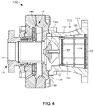
FIGURE 4 depicts a side, sectional view of an apparatus for retaining a noise attenuation assembly of the present disclosure, the apparatus and the noise attenuation assembly coupled to a fluid regulating device; -
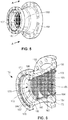
FIGURE 5 depicts a perspective view of the apparatus for retaining a noise attenuation assembly ofFIGURE 4 ; -
FIGURE 6 depicts a cross-sectional view of the apparatus for retaining a noise attenuation assembly taken along the lines A-A ofFIGURE 5 ; -
FIGURE 7 depicts a side view of the apparatus ofFIGURE 6 ; -
FIGURE 8 depicts a front view of the apparatus for retaining a noise attenuation assembly ofFIGURE 5 ; and -
FIGURE 9 depicts a side, sectional view of another noise attenuation assembly and apparatus for retaining the noise attenuation assembly. - Generally, an apparatus for retaining a noise attenuation assembly for a fluid regulating device is disclosed, the noise attenuation assembly including a front plate, a middle plate, and a rear plate disposed within the cylindrical body. The apparatus includes a plurality of rods, the plurality of rods including six rods, each rod having a front end, a middle portion, and a rear end. The front end of each rod is disposed in an outer edge of the front plate, the middle portion of each rod is disposed in an outer edge of the middle plate, and the rear end of each rod is disposed in the outer edge of the rear plate. So configured, the six rods are equidistantly disposed around the outer edges of each of the front plate, the middle plate, and the rear plate of the noise attenuation assembly. As a result, stresses during operation of the fluid regulating device are distributed away from the center of the plates, for example, and toward the outer edges, strengthening and prolonging the useful life of the plates and simplifying the design of the noise attenuation assembly.
- Referring now to
Figure 4 , anapparatus 100 for retaining anoise attenuation assembly 112 for use with afluid regulating device 120 is depicted. Thefluid regulating device 120 includes avalve 130 having aninlet 132, anoutlet 134, and avalve seat 136 disposed between theinlet 132 and theoutlet 134 for allowing fluid to flow through thevalve 130, for example. - An
actuator 140 is coupled to thevalve 130 and has a control assembly 142. The control assembly 142 includes acontrol element 144, such as a valve plug, and adiaphragm 146 operably connected to thecontrol element 144. As depicted inFigure 4 , thecontrol element 144 is disposed within thevalve 130 and adapted to be displaced relative to thevalve seat 136 for controlling the flow of a fluid between theinlet 132 and theoutlet 134. - The
noise attenuation assembly 112 is coupled to thevalve 130, such as theoutlet 134 of thevalve 130, and includes acylindrical body 150, as depicted inFigures 4 and5 . While thebody 150 is largely cylindrical in shape, one of ordinary skill in the art will appreciate that the shape and/or configuration of thebody 150 of thenoise attenuation assembly 112 may take the form of various other shapes and sizes and still fall within the scope of the present disclosure. The body includes afront end 152 that is coupled to theoutlet 134, in one example, arear end 154, and aninside surface 155. - The
noise attenuation assembly 112 further includes at least one plate. In one example, and as depicted inFigures 4 and6 , for example, three plates are included. More specifically, afront plate 157 is disposed within thecylindrical body 150 near thefront end 152 of the cylindrical body. Amiddle plate 158 is likewise disposed within thecylindrical body 150, and arear plate 159 is also disposed within thecylindrical body 150 near therear end 154 of thecylindrical body 150. Each of thefront plate 157, themiddle plate 158, and therear plate 159 includes anouter edge rear plates Figure 6 , for example, and still fall within the scope of the present disclosure. For example, themiddle plate 158 may be disposed at a position closer to thefront plate 157 than therear plate 159. In another example, themiddle plate 158 may be disposed closer to therear plate 159 than thefront plate 157, as depicted inFigure 7 . In yet another example, themiddle plate 158 may be disposed a distance from thefront plate 157 equal to a distance from therear plate 159. Said another way, themiddle plate 158 may be disposed at a center point of the distance between the front andrear plates middle plate 158 may be eliminated or may be in contact with one or more of thefront plate 157 or therear plate 159. Although not depicted, a fourth and a fifth plate may be added to thenoise attenuation assembly 112 and still fall within the scope of the present disclosure. - Referring now to
Figures 6 and7 , theapparatus 100 for retaining the at least one plate of thenoise attenuation assembly 112 includes a plurality ofrods 170. The plurality ofrods 170 is coupled to at least oneplate noise attenuation assembly 112. More specifically, in one example, the at least onerod 172 of the plurality ofrods 170 includes afirst end 174, such asfront end 174, as depicted inFigure 7 , that is disposed through theouter edge 160 of thefront plate 157. So configured, theapparatus 100 supports and strengthens the at least one plate, such as thefront plate 157, and directs stress during operation of thefluid regulating device 120 toward the outer edges of theplates - In one example, and as depicted in
Figure 7 , for example, thefront plate 157 includes anouter surface 180, themiddle plate 158 includes anouter surface 182, and therear plate 159 likewise includes anouter surface 184. Eachouter surface rear plates inner surface 155 of thecylindrical body 150 of thenoise attenuation assembly 120 in a press-fit manner to help secure theplates body 150. As one of ordinary skill in the art will appreciate, each of theouter surfaces plates inside surface 155 or another part of thecylindrical body 150 and still fall within the scope of the present disclosure. - In another example, the at least one
rod 172 of the plurality ofrods 170 has thefront end 174, amiddle portion 176, and arear end 178, therear end 178 disposed on the opposite end of therod 172 as thefront end 174. As depicted inFigure 7 , for example, thefront end 174 is disposed in theouter edge 160 of thefront plate 157, themiddle portion 176 is disposed in theouter edge 162 of themiddle plate 158, and therear portion 178 is disposed in theouter edge 164 of therear plate 159. - In one example, the plurality of
rods 170 includes six rods 172 (Figure 8 ), and each of the sixrods 172 likewise includes thefront end 174 disposed within theouter edge 160 of thefront plate 157, themiddle portion 176 disposed within theouter edge 162 of themiddle plate 158, and therear end 178 disposed within theouter edge 164 of therear plate 159. So configured, the sixrods 172 are equidistantly spaced from each other around eachouter edge rear plates rod 162 is spaced a distance from the adjacent ornext rod 162 that is equal to each distance between each of therods 162 disposed around theouter edges fluid regulating valve 120 are distributed towards theouter edges - As further depicted in
Figures 6 and7 , anut 186, such as one or more of a locking nut or a threaded nut, secures eachrod 172 of the plurality ofrods 170 to theouter edges rear plates noise attenuation assembly 112. More specifically, thenut 186 secures thefront end 174 of eachrod 172 to thefront plate 157 by contacting a rear surface 187 of thefront plate 157. In a similar manner, anut 186 also secures themiddle portion 176 of eachrod 172 of the plurality ofrods 170 to themiddle plate 158 by contacting arear surface 188 of themiddle plate 158. Likewise,nuts 186 also secure therear portions 178 of eachrod 172 to therear plate 159, also contacting arear surface 189 of therear plate 159. - Further, the
apparatus 100 for retaining thenoise attenuation assembly 112 further includes afront support member 190 coupled to, such as in contact with, afront surface 191 of thefront plate 157 and through which the at least onerod 172 is disposed and secured. More specifically, and as depicted inFigures 6 and7 , thefront support member 190 is a ring or circular in shape and is in direct contact with thefront surface 191 of thefront plate 157 along theouter edge 160 of thefront plate 157. Eachfront end 174 of therod 172 of the plurality ofrods 170 is disposed in theouter edge 160 of thefront plate 157 and thefront support member 190 of theapparatus 100. In addition, anut 186, such as a threaded locking nut, for example, is also used to secure thefront end 174 of the eachrod 172 to thefront support member 190. In one example, eachnut 186 contacts afront surface 192 of thefront support member 190 to further secure the front ends 174 of eachrod 172 of the plurality ofrods 170 to thefront support member 190. Said another way, the front ends 174 of eachrod 172 are secured on one side to thefront support member 190 by anut 186 and also secured on the other side to the rear surface 187 of thefront plate 157 by anothernut 186. - Still further, the
apparatus 100 for retaining thenoise attenuation assembly 112 further includes a rear support member 194 (Figure 7 ) one or more of coupled to or in contact with therear surface 189 of therear plate 159 and through which at least onerod 172 of the plurality ofrods 170 is disposed. More specifically, therear support member 194 is a ring or circular in shape and is in direct contact with therear surface 189 of therear plate 159 along theouter edge 164 of therear plate 159. Eachrear end 178 of therod 172 of the plurality ofrods 170 is disposed in theouter edge 164 of therear plate 159 and therear support member 194 of theapparatus 100. In addition,nuts 186, such as threaded locking nuts, for example, are also used to secure therear end 178 of the eachrod 172 to therear plate 159 and therear support member 194. In one example, eachnut 186 contacts arear surface 195 of therear support member 194 to further secure the rear ends 178 of eachrod 172 of the plurality ofrods 170 to therear support member 194 and therear plate 159. - Referring now to
Figure 9 , another exemplarynoise attenuation assembly 212 and anapparatus 200 for retaining thenoise attenuation assembly 212 is depicted. InFigure 9 , elements of both thenoise attenuation assembly 212 and theapparatus 200 for retaining thenoise attenuation assembly 212 that are identical to or the same as elements of thenoise attenuation assembly 112 and theapparatus 100 for retaining the noise attenuation assembly ofFigures 1-8 havereference numbers 100 greater than the reference numbers of thenoise attenuation assembly 112 and theapparatus 100. - Like the
noise attenuation assembly 112, thenoise attenuation assembly 212 is coupled to thevalve 130, such as theoutlet 134 of thevalve 130, and includes acylindrical body 250. While thebody 250 is largely cylindrical in shape, one of ordinary skill in the art will appreciate that the shape and/or configuration of thebody 250 of thenoise attenuation assembly 212 may take the form of various other shapes and sizes and still fall within the scope of the present disclosure. The body includes afront end 252 that is coupled to theoutlet 134, in one example, arear end 254, and aninside surface 255. - The
noise attenuation assembly 212 further includes at least one plate. More specifically, in this example, afront plate 257 is disposed within thecylindrical body 250 near thefront end 252 of the cylindrical body. Amiddle plate 258 is likewise disposed within thecylindrical body 250, and arear plate 259 is also disposed within thecylindrical body 250 near therear end 254 of thecylindrical body 250. Each of thefront plate 257, themiddle plate 258, and therear plate 259 includes anouter edge middle plate 258 is disposed closer to therear plate 259 than thefront plate 257. Threeadditional plates front plate 257 and themiddle plate 258. More specifically, a first plate 222 of the three additional plates is disposed immediately adjacent to thefront plate 257. Athird plate 226 of the three additional plates is disposed next to themiddle plate 258, and asecond plate 224 of the three additional plates is disposed between the first plate 222 and thethird plate 226. - Like the
apparatus 100 for retaining the at least one plate of thenoise attenuation assembly 112, theapparatus 200 for retaining the at least one plate of thenoise attenuation assembly 212 includes a plurality of rods 270. The plurality of rods 270 is coupled to at least oneplate noise attenuation assembly 212. More specifically, in one example, the at least onerod 272 of the plurality of rods 270 includes afirst end 274, such asfront end 274, as depicted inFigure 9 , that is disposed through theouter edge 260 of thefront plate 257. According to the invention, theapparatus 200 supports and strengthens the at least one plate, such as thefront plate 257, and directs stress during operation of thefluid regulating device 120 toward the outer edges of theplates - In another example, the at least one
rod 272 of the plurality of rods 270 has thefront end 274, amiddle portion 276, and arear end 278, therear end 278 disposed on the opposite end of therod 272 as thefront end 274. As depicted inFigure 9 , for example, thefront end 274 is disposed in theouter edge 260 of thefront plate 257, themiddle portion 276 is disposed in theouter edge 262 of themiddle plate 258, and therear portion 278 is disposed in theouter edge 264 of therear plate 259. In addition, the at least onerod 272 of the plurality of rods is also disposed in anouter edge 223 of the first plate 222 of the three additional plates of thenoise attenuation assembly 212, anouter edge 225 of thesecond plate 224 of the three additional plates, and anouter edge 227 of thethird plate 226 of the three additional plates. - In one example, the plurality of rods 270 includes six rods 272 (not shown), and each of the six
rods 272 likewise includes thefront end 274 disposed within theouter edge 260 of thefront plate 257, themiddle portion 276 disposed within theouter edge 262 of themiddle plate 258, and therear end 278 disposed within theouter edge 264 of therear plate 259. In addition, each of the sixrods 272 also includes a portion disposed in theouter edge 223 of the first plate 222, theouter edge 225 of thesecond plate 224, and theouter edge 227 of thethird plate 226. So configured, the sixrods 272 are equidistantly spaced from each other around eachouter edge plates rod 262 is spaced a distance from the adjacent ornext rod 262 that is equal to each distance between each of therods 262 disposed around theouter edges fluid regulating valve 120 are distributed towards one or more of theouter edges - As further depicted in
Figure 9 , anut 286, such as one or more of a locking nut or a threaded nut, secures eachrod 272 of the plurality of rods 270 to theouter edges plates noise attenuation assembly 212. - Further, the
apparatus 200 for retaining thenoise attenuation assembly 212 further includes afront support member 290 coupled to, such as in contact with, afront surface 291 of thefront plate 257 and through which the at least onerod 272 is disposed and secured. Thefront support member 290 may be a ring or circular in shape and is in direct contact with thefront surface 291 of thefront plate 257 along theouter edge 260 of thefront plate 257. Eachfront end 274 of therod 272 of the plurality of rods 270 is disposed in theouter edge 260 of thefront plate 257 and thefront support member 290 of theapparatus 200. In addition, anut 286, such as a threaded locking nut, for example, is also used to secure thefront end 274 of the eachrod 272 to thefront support member 290. In one example, eachnut 286 contacts afront surface 292 of thefront support member 290 to further secure the front ends 274 of eachrod 272 of the plurality of rods 270 to thefront support member 290. - Still further, the
apparatus 200 for retaining thenoise attenuation assembly 212 further includes arear support member 294 one or more of coupled to or in contact with the rear surface 289 of therear plate 259 and through which at least onerod 272 of the plurality of rods 270 is disposed. More specifically, therear support member 294 may be a ring or circular in shape and is in direct contact with the rear surface 289 of therear plate 259 along theouter edge 264 of therear plate 259. Eachrear end 278 of therod 272 of the plurality of rods 270 is disposed in theouter edge 264 of therear plate 259 and therear support member 294 of theapparatus 200. In addition,nuts 286, such as threaded locking nuts, for example, are also used to secure therear end 278 of the eachrod 272 to therear plate 259 and therear support member 294. In one example, eachnut 286 contacts arear surface 295 of therear support member 294 to further secure the rear ends 278 of eachrod 272 of the plurality of rods 270 to therear support member 294 and therear plate 259. - As one of ordinary skill in the art will appreciate, the
nuts nuts rods rods 170, 270 are threaded, one of ordinary skill in the art will further understand that therods rods - Still further, while the front and
rear support members rear support members rear support members rods - In addition, while not depicted in any of the figures, one of ordinary skill in the art will still further understand that
fewer rods rods 170, 270 may be used and still fall within the scope of the present disclosure. In one example, the plurality ofrods 170, 270 may include only two rods, equidistantly disposed from each other along theouter edges plates rods 170, 270 may include threerods rods outer edges plates outer edges plates rod rods 170, 270 in any number configuration may include only somerods other rods - In view of the foregoing, one of ordinary skill in the art will further appreciate the following example method for retaining the
plates noise attenuation assembly fluid regulating device 120. More specifically, the method for retaining thenoise attenuation assembly fluid regulating device 120 includes providing the plurality ofrods 170, 270. The method further includes disposing at least onerod outer edges front plate middle plate rear plate noise attenuation assembly fluid regulating device 120, 220 toward theouter edges plates - In addition, and in one example, the method may further comprise securing the at least one
rod rods 170, 270 disposed in theouter edge rear plates 157, 257,158, 258, 159, 259, respectively, via one ormore nuts rods rods 170, 270 in theouter edges rear plates front end rod rods 170, 270 in thefront plate middle portion rod middle plate rear end portion rod rear plate - Further, the method may further comprise coupling the
front support member front surface front plate front end rods 170, 270 is disposed in thefront support member rear support member rear surface 189, 289 of therear plate rear end rod rods 170, 270 is disposed in therear support member - Overall, one of ordinary skill in the art will appreciate the various advantages of the
new apparatus noise attenuation assembly apparatus front plate fluid regulating device 120 toward the outer edges of theplates rear support members plates plates fluid regulating device 120, while still reducing and suppressing noise from thefluid regulating device 120. Still further, by providing more than one rod disposed on the outer edges of theplates rear support members cage 22 of theconventional apparatus 10 and springs (not shown) typically disposed within thecage 22 to suppress the sound of the fluid flowing through outlet, for example, are not needed. As a result, the design of thenoise attenuation assembly new apparatus - The
fluid regulating device 120 described herein is merely one example of a fluid control device incorporating the principles of the present disclosure. Other fluid control devices including other regulators and control valves may also benefit from the structures and/or advantages of the present disclosure. More generally, although certain example apparatus and methods have been described herein, the scope of coverage of this patent is not limited thereto. On the contrary, this patent covers all methods, apparatus and articles of manufacture fairly falling within the scope of the appended claims either literally or under the doctrine of equivalents. - Throughout this specification, plural instances may implement components, operations, or structures described as a single instance. Although individual operations of one or more methods are illustrated and described as separate operations, one or more of the individual operations may be performed concurrently, and nothing requires that the operations be performed in the order illustrated. Structures and functionality presented as separate components in example configurations may be implemented as a combined structure or component. Similarly, structures and functionality presented as a single component may be implemented as separate components. These and other variations, modifications, additions, and improvements fall within the scope of the subject matter herein.
- As used herein any reference to "one example" or "an example" means that a particular element, feature, structure, or characteristic described in connection with the embodiment is included in at least one embodiment. The appearances of the phrase "in one example" in various places in the specification are not necessarily all referring to the same example.
- Some examples may be described using the expression "coupled" and "connected" along with their derivatives. For example, some examples may be described using the term "coupled" to indicate that two or more elements are in direct physical or electrical contact. The term "coupled," however, may also mean that two or more elements are not in direct contact with each other, but yet still cooperate or interact with each other. The examples are not limited in this context.
- As used herein, the terms "comprises," "comprising," "includes," "including," "has," "having" or any other variation thereof, are intended to cover a non-exclusive inclusion. For example, a process, method, article, or apparatus that comprises a list of elements is not necessarily limited to only those elements but may include other elements not expressly listed or inherent to such process, method, article, or apparatus. Further, unless expressly stated to the contrary, "or" refers to an inclusive or and not to an exclusive or. For example, a condition A or B is satisfied by any one of the following: A is true (or present) and B is false (or not present), A is false (or not present) and B is true (or present), and both A and B are true (or present).
- In addition, use of the "a" or "an" are employed to describe elements and components of the embodiments herein. This is done merely for convenience and to give a general sense of the description. This description, and the claims that follow, should be read to include one or at least one and the singular also includes the plural unless it is obvious that it is meant otherwise.
Claims (15)
- A fluid regulating device comprising:a valve (130) having an inlet (132), an outlet (134), and a valve seat (136) disposed between the inlet and the outlet for allowing fluid to flow through the valve;an actuator (140) coupled to the valve (130) and having a control assembly (142), the control assembly comprising a control element (144) and a diaphragm (146) operably connected to the control element (144), the control element (144) disposed within the valve (130) and adapted to be displaced relative to the valve seat for controlling the flow of a fluid between the inlet (132) and the outlet (134);a noise attenuation assembly (112, 212) coupled to the outlet (134), the noise attenuation assembly including a body (150, 250) and at least one plate (157, 158, 159, 257, 258, 259) having an outer edge (160, 162, 164, 260, 262, 264) and disposed within the body (150, 250); and characterised byan apparatus (100, 200) for retaining the at least one plate of the noise attenuation assembly (112, 212), the apparatus including a plurality of rods (170, 270) coupled to the at least one plate (157, 158, 159, 257, 258, 259), the plurality of rods including at least one rod (172, 272) disposed through the outer edge (160, 162, 164, 260, 262, 264) of each plate (157, 158, 159, 257, 258, 259).
- The device of claim 1, wherein the noise attenuation assembly (112, 212) includes three plates (157, 158, 159, 257, 258, 259) disposed within the cylindrical body (150, 250), the three plates including a front plate (157, 257), a middle plate (158, 258), and a rear plate (159, 259), each of the front, middle and rear plates having the outer edge (160, 162, 164, 260, 262, 264) and an outer surface (180, 182, 184), the outer surface of each plate contacting an inner surface (155) of the cylindrical body (150).
- The device of claim 2, wherein the at least one rod (172, 272) of the plurality of rods has a front end (174, 274), a middle portion (176, 276), and a rear end (178, 278), the front end disposed within the outer edge (160, 260) of the front plate (157, 257), the middle portion (176, 276) disposed within the outer edge (162, 262) of the middle plate (158, 258), and the rear end (178, 278) disposed within the outer edge (164, 264) of the rear plate (159, 259).
- The device of claim 2, wherein the plurality of rods (170, 270) includes six rods (172, 272) disposed within each of the front, middle and rear plates (157, 158, 159, 257, 258, 259) around the outer edges (160, 162, 164, 260, 262, 264) of each of the front, middle, and rear plates.
- The device of claim 2, wherein the apparatus (100, 200) for retaining the at least one plate further includes a front support member (190, 290) coupled to a front surface (191, 291) of the front plate (157, 257) and through which the at least one rod (172, 272) of the plurality of rods (170, 270) is disposed and secured.
- The device of claim 2, wherein the apparatus (100, 200) for retaining the at least one plate further includes a rear support member (194, 294) coupled to a rear surface (189, 289) of the rear plate (159, 259) and through which the at least one rod (172, 272) of the plurality of rods (170, 270) is disposed and secured.
- An apparatus for retaining the noise attenuation assembly (112, 212) within the fluid regulating device (120) according to claim 1, the noise attenuation assembly (112, 212) including a front plate (157, 257), a middle plate (158, 258), and a rear plate (159, 259), each of the front, middle and rear plates having an outer edge (160, 162, 164, 260, 262, 264) and disposed within the body (150, 250),
wherein the at least one rod (172, 272) is disposed in the outer edge (160, 162, 164, 260, 262, 264) of one or more of the front plate (157, 257), the middle plate (158, 258), and the rear plate (159, 259). - The apparatus of claim 7, wherein each rod of the plurality of rods (170, 270) includes a front end (174, 274), a middle portion (176, 276), and a rear end (178, 278), each front end disposed within the outer edge (160, 260) of the front plate (157, 257), each middle portion (176, 276) disposed within the outer edge (162, 262) of the middle plate (158, 258), and each rear end (178, 278) disposed within the outer edge (164, 264) of the rear plate (159, 259), such that the rods (172, 272) are equidistantly disposed around each outer edge of the front plate, the middle plate, and the rear plate of the noise attenuation assembly (112, 212), distributing stress towards the outer edges.
- The apparatus of any preceding claim 7 or 8, wherein a nut (186, 286) secures each rod (172, 272) of the plurality of rods to the outer edges of each of the front, middle, and rear plates.
- The apparatus of any preceding claim 7 to 9, the noise attenuation assembly (112, 212) further comprising three additional plates (222, 224, 226) disposed between the front plate and the middle plate, each of the three additional plates including an outer edge (223, 225, 227), wherein the at least one rod (272) is disposed in the outer edge of each of the front, middle, and rear plates (157, 158, 159, 257, 258, 259) and the three additional plates (222, 224, 226) disposed between the front plate and the middle plate.
- A method for retaining a noise attenuation assembly (112, 212) for use with the fluid regulating device (120) of claim 1, the noise attenuation assembly including a front plate (157, 257), a middle plate (158, 258), and a rear plate (159, 259), each of the front, middle and rear plates having an outer edge (160, 162, 164, 260, 262, 264) and disposed within the body (150, 250), the method being characterised by comprising:providing the plurality of rods (170, 270); anddisposing the at least one rod (172, 272) of the plurality of rods within the outer edge (160, 162, 164, 260, 262, 264) of one or more of the front, middle or rear plates (157, 158, 159, 257, 258, 259) of the noise attenuation assembly (112, 212) to distribute stress during operation of the fluid regulating valve toward the outer edges of the plates.
- The method of claim 11, wherein the method further comprises securing the at least one rod (172, 272) of the plurality of rods disposed in the outer edge of one or more of the front, middle or rear plates of the noise attenuation assembly (112, 212) via a nut (186, 286).
- The method of claim 11, wherein disposing at least one rod (172, 272) of the plurality of rods in the outer edge of one or more of the front, middle or rear plates (157, 158, 159, 257, 258, 259) includes disposing six rods of the plurality of rods in one or more of: (1) the outer edges (160, 162, 164, 260, 262, 264) of each of the front, middle, and rear plates (157, 158, 159, 257, 258, 259); or (2) the outer edges of each of the front, middle, and rear plates and an outer edge (223, 225, 227) of each of three additional plates (222, 224, 226) disposed between the front plate and the middle plate.
- The method of claim 11, wherein disposing at least one rod (172, 272) of the plurality of rods in an outer edge of one or more of the front, middle or rear plates (157, 158, 159, 257, 258, 259) includes disposing a front end (174, 274) of each rod in the front plate (157, 257), disposing a corresponding middle portion (176, 276) of each rod in the middle plate (158, 258), and disposing a corresponding rear end (178, 278) of each rod in the rear plate (159, 259).
- The method of claim 11, further comprising coupling one or more of: (1) a front support member (190, 290) to a front surface (191, 291) of the front plate (157, 257), wherein a front end (174, 274) of the at least one rod (172, 272) of the plurality of rods is disposed in the front support member; or (2) a rear support member (194, 294) to a rear surface (189, 289) of the rear plate (159, 259), wherein a rear end (178, 278) of at least one rod (172, 272) of the plurality of rods is disposed in the rear support member.
Applications Claiming Priority (2)
| Application Number | Priority Date | Filing Date | Title |
|---|---|---|---|
| US15/254,805 US20180058606A1 (en) | 2016-09-01 | 2016-09-01 | Apparatus and method for retaining a noise attenuation assembly for use with a pressure regulator |
| PCT/US2017/048526 WO2018044701A1 (en) | 2016-09-01 | 2017-08-25 | Apparatus and method for retaining a noise attenuation assembly for use with a pressure regulator |
Publications (2)
| Publication Number | Publication Date |
|---|---|
| EP3507667A1 EP3507667A1 (en) | 2019-07-10 |
| EP3507667B1 true EP3507667B1 (en) | 2021-08-18 |
Family
ID=59829471
Family Applications (1)
| Application Number | Title | Priority Date | Filing Date |
|---|---|---|---|
| EP17764712.0A Active EP3507667B1 (en) | 2016-09-01 | 2017-08-25 | Apparatus and method for retaining a noise attenuation assembly for use with a pressure regulator |
Country Status (5)
| Country | Link |
|---|---|
| US (2) | US20180058606A1 (en) |
| EP (1) | EP3507667B1 (en) |
| CN (2) | CN207848581U (en) |
| MX (1) | MX2019002399A (en) |
| WO (1) | WO2018044701A1 (en) |
Families Citing this family (4)
| Publication number | Priority date | Publication date | Assignee | Title |
|---|---|---|---|---|
| US11592529B2 (en) * | 2019-07-01 | 2023-02-28 | Pony Ai Inc. | System and method for reducing noise into an enclosure |
| EP4072717B1 (en) * | 2019-12-11 | 2026-04-22 | Unibio A/S | Static mixer element and reactor comprising a static mixer element |
| CA3102540A1 (en) * | 2019-12-13 | 2021-06-13 | SPL Control Inc. | Refractory core with enhanced acoustic properties |
| EP4315314A1 (en) * | 2021-03-23 | 2024-02-07 | Technische Universiteit Eindhoven | Anechoic termination for acoustic plane wave suppression |
Family Cites Families (19)
| Publication number | Priority date | Publication date | Assignee | Title |
|---|---|---|---|---|
| US825010A (en) * | 1905-12-27 | 1906-07-03 | Benjamin W Snow | Muffler. |
| US3003516A (en) * | 1957-04-08 | 1961-10-10 | Granberg Corp | Flow control valve assembly |
| DE1261712B (en) * | 1962-12-10 | 1968-02-22 | Wiener Starkstromwerke Ges M B | Throttle device for low-noise expansion of a gas flow in a pipeline |
| US3690344A (en) * | 1971-02-08 | 1972-09-12 | Grove Valve & Regulator Co | Silent flexible tube type valve |
| FR2315051A1 (en) * | 1975-06-20 | 1977-01-14 | Bertin & Cie | SOUNDPROOF VALVE |
| LU74505A1 (en) * | 1976-03-08 | 1976-09-01 | ||
| US4751980A (en) * | 1986-10-20 | 1988-06-21 | Devane Harry M | Sound attenuation apparatus |
| US5398589A (en) * | 1994-01-12 | 1995-03-21 | Wright Malta Corporation | Large caliber gun muffler |
| US7011180B2 (en) * | 2002-09-18 | 2006-03-14 | Savant Measurement Corporation | System for filtering ultrasonic noise within a fluid flow system |
| US7100737B2 (en) * | 2003-07-28 | 2006-09-05 | Carrier Corporation | Muffler for noise reduction |
| US7766045B2 (en) * | 2006-07-31 | 2010-08-03 | Fisher Controls International Llc | Fluid pressure reduction device for high pressure-drop ratios |
| WO2009088085A1 (en) * | 2008-01-10 | 2009-07-16 | Mg Grow Up Corp. | Static fluid mixer |
| CN101270819A (en) * | 2008-05-08 | 2008-09-24 | 四川华林自控科技有限公司 | High pressure-difference sleeve valve |
| US8307943B2 (en) * | 2010-07-29 | 2012-11-13 | General Electric Company | High pressure drop muffling system |
| US9010371B2 (en) * | 2011-12-16 | 2015-04-21 | Cla-Val Co. | Anti-cavitation valve seat |
| US20140069737A1 (en) * | 2012-09-10 | 2014-03-13 | Dresser Inc. | Noise attenuation device and fluid coupling comprised thereof |
| US9587765B2 (en) * | 2014-04-22 | 2017-03-07 | Emerson Process Management Regulator Technologies, Inc. | Sound treatment assembly for a fluid transmission line |
| US9739408B2 (en) * | 2016-01-15 | 2017-08-22 | Emerson Process Management Regulator Technologies, Inc. | Noise attenuation apparatus for fluid devices |
| US9534725B1 (en) * | 2016-01-15 | 2017-01-03 | Emerson Process Management Regulator Technologies, Inc. | Noise-attenuation apparatus for pressure regulators |
-
2016
- 2016-09-01 US US15/254,805 patent/US20180058606A1/en not_active Abandoned
-
2017
- 2017-08-25 MX MX2019002399A patent/MX2019002399A/en unknown
- 2017-08-25 EP EP17764712.0A patent/EP3507667B1/en active Active
- 2017-08-25 WO PCT/US2017/048526 patent/WO2018044701A1/en not_active Ceased
- 2017-09-01 CN CN201721122050.2U patent/CN207848581U/en active Active
- 2017-09-01 CN CN201710779585.5A patent/CN107795743B/en active Active
-
2019
- 2019-10-30 US US16/668,468 patent/US11261999B2/en active Active
Non-Patent Citations (1)
| Title |
|---|
| None * |
Also Published As
| Publication number | Publication date |
|---|---|
| MX2019002399A (en) | 2019-07-08 |
| WO2018044701A1 (en) | 2018-03-08 |
| CN107795743B (en) | 2021-12-24 |
| US11261999B2 (en) | 2022-03-01 |
| EP3507667A1 (en) | 2019-07-10 |
| CN207848581U (en) | 2018-09-11 |
| US20180058606A1 (en) | 2018-03-01 |
| CN107795743A (en) | 2018-03-13 |
| US20200063893A1 (en) | 2020-02-27 |
Similar Documents
| Publication | Publication Date | Title |
|---|---|---|
| US11261999B2 (en) | Apparatus and method for retaining a noise attenuation assembly for use with a pressure regulator | |
| JP6257581B2 (en) | Fluid regulator with improved flow stability | |
| US9410638B2 (en) | Solenoid valve with shaped spring | |
| JP4328022B2 (en) | Check valve | |
| KR102207127B1 (en) | Diaphragm valve with welded diaphragm seat carrier | |
| US6945539B2 (en) | Seal retainer | |
| CN110081052A (en) | Squeeze limitation fastening system | |
| US9551406B2 (en) | Securing device for an actuating lever | |
| JP2016153689A (en) | Dual p-clamp assembly | |
| US9309833B2 (en) | Leaf spring hanger for exhaust duct liner | |
| EP2980461B1 (en) | Check valves | |
| CN108713119B (en) | Lockable friction joint for adjusting relative pivotal positioning of pipe segments | |
| US20160109027A1 (en) | Valve seat and valve disc with cascaded geometries | |
| WO2013126850A1 (en) | Oblique mating surfaces in a valve assembly | |
| JPH049492Y2 (en) | ||
| US11300213B1 (en) | Floating yoke connection | |
| US9739174B2 (en) | Panel connection system and a method of using the same | |
| US20250109773A1 (en) | Floating brake rotor assembly | |
| CN111795188B (en) | Valve device | |
| EP3938304B1 (en) | Handling bar for laminated or film supports | |
| JP7010752B2 (en) | duct | |
| KR20150133969A (en) | Separation pneumatic connector | |
| WO2023094932A1 (en) | Sealing system for mechanical members | |
| WO2025186523A8 (en) | Assembly for an aircraft propulsion unit designed to facilitate the installation of elements close to one another |
Legal Events
| Date | Code | Title | Description |
|---|---|---|---|
| STAA | Information on the status of an ep patent application or granted ep patent |
Free format text: STATUS: UNKNOWN |
|
| STAA | Information on the status of an ep patent application or granted ep patent |
Free format text: STATUS: THE INTERNATIONAL PUBLICATION HAS BEEN MADE |
|
| PUAI | Public reference made under article 153(3) epc to a published international application that has entered the european phase |
Free format text: ORIGINAL CODE: 0009012 |
|
| STAA | Information on the status of an ep patent application or granted ep patent |
Free format text: STATUS: REQUEST FOR EXAMINATION WAS MADE |
|
| 17P | Request for examination filed |
Effective date: 20190225 |
|
| AK | Designated contracting states |
Kind code of ref document: A1 Designated state(s): AL AT BE BG CH CY CZ DE DK EE ES FI FR GB GR HR HU IE IS IT LI LT LU LV MC MK MT NL NO PL PT RO RS SE SI SK SM TR |
|
| AX | Request for extension of the european patent |
Extension state: BA ME |
|
| DAV | Request for validation of the european patent (deleted) | ||
| DAX | Request for extension of the european patent (deleted) | ||
| STAA | Information on the status of an ep patent application or granted ep patent |
Free format text: STATUS: EXAMINATION IS IN PROGRESS |
|
| 17Q | First examination report despatched |
Effective date: 20200507 |
|
| REG | Reference to a national code |
Ref country code: DE Ref legal event code: R079 Ref document number: 602017044321 Country of ref document: DE Free format text: PREVIOUS MAIN CLASS: G05D0007010000 Ipc: F16K0001120000 |
|
| RIC1 | Information provided on ipc code assigned before grant |
Ipc: F16L 55/027 20060101ALI20201215BHEP Ipc: F16K 31/126 20060101ALI20201215BHEP Ipc: F16K 1/12 20060101AFI20201215BHEP Ipc: F16K 47/08 20060101ALI20201215BHEP |
|
| GRAP | Despatch of communication of intention to grant a patent |
Free format text: ORIGINAL CODE: EPIDOSNIGR1 |
|
| STAA | Information on the status of an ep patent application or granted ep patent |
Free format text: STATUS: GRANT OF PATENT IS INTENDED |
|
| INTG | Intention to grant announced |
Effective date: 20210311 |
|
| GRAS | Grant fee paid |
Free format text: ORIGINAL CODE: EPIDOSNIGR3 |
|
| GRAA | (expected) grant |
Free format text: ORIGINAL CODE: 0009210 |
|
| STAA | Information on the status of an ep patent application or granted ep patent |
Free format text: STATUS: THE PATENT HAS BEEN GRANTED |
|
| AK | Designated contracting states |
Kind code of ref document: B1 Designated state(s): AL AT BE BG CH CY CZ DE DK EE ES FI FR GB GR HR HU IE IS IT LI LT LU LV MC MK MT NL NO PL PT RO RS SE SI SK SM TR |
|
| REG | Reference to a national code |
Ref country code: GB Ref legal event code: FG4D |
|
| REG | Reference to a national code |
Ref country code: CH Ref legal event code: EP |
|
| REG | Reference to a national code |
Ref country code: DE Ref legal event code: R096 Ref document number: 602017044321 Country of ref document: DE |
|
| REG | Reference to a national code |
Ref country code: IE Ref legal event code: FG4D Ref country code: AT Ref legal event code: REF Ref document number: 1421937 Country of ref document: AT Kind code of ref document: T Effective date: 20210915 |
|
| REG | Reference to a national code |
Ref country code: LT Ref legal event code: MG9D |
|
| REG | Reference to a national code |
Ref country code: NL Ref legal event code: MP Effective date: 20210818 |
|
| REG | Reference to a national code |
Ref country code: AT Ref legal event code: MK05 Ref document number: 1421937 Country of ref document: AT Kind code of ref document: T Effective date: 20210818 |
|
| PG25 | Lapsed in a contracting state [announced via postgrant information from national office to epo] |
Ref country code: RS Free format text: LAPSE BECAUSE OF FAILURE TO SUBMIT A TRANSLATION OF THE DESCRIPTION OR TO PAY THE FEE WITHIN THE PRESCRIBED TIME-LIMIT Effective date: 20210818 Ref country code: SE Free format text: LAPSE BECAUSE OF FAILURE TO SUBMIT A TRANSLATION OF THE DESCRIPTION OR TO PAY THE FEE WITHIN THE PRESCRIBED TIME-LIMIT Effective date: 20210818 Ref country code: HR Free format text: LAPSE BECAUSE OF FAILURE TO SUBMIT A TRANSLATION OF THE DESCRIPTION OR TO PAY THE FEE WITHIN THE PRESCRIBED TIME-LIMIT Effective date: 20210818 Ref country code: LT Free format text: LAPSE BECAUSE OF FAILURE TO SUBMIT A TRANSLATION OF THE DESCRIPTION OR TO PAY THE FEE WITHIN THE PRESCRIBED TIME-LIMIT Effective date: 20210818 Ref country code: BG Free format text: LAPSE BECAUSE OF FAILURE TO SUBMIT A TRANSLATION OF THE DESCRIPTION OR TO PAY THE FEE WITHIN THE PRESCRIBED TIME-LIMIT Effective date: 20211118 Ref country code: AT Free format text: LAPSE BECAUSE OF FAILURE TO SUBMIT A TRANSLATION OF THE DESCRIPTION OR TO PAY THE FEE WITHIN THE PRESCRIBED TIME-LIMIT Effective date: 20210818 Ref country code: PT Free format text: LAPSE BECAUSE OF FAILURE TO SUBMIT A TRANSLATION OF THE DESCRIPTION OR TO PAY THE FEE WITHIN THE PRESCRIBED TIME-LIMIT Effective date: 20211220 Ref country code: NO Free format text: LAPSE BECAUSE OF FAILURE TO SUBMIT A TRANSLATION OF THE DESCRIPTION OR TO PAY THE FEE WITHIN THE PRESCRIBED TIME-LIMIT Effective date: 20211118 Ref country code: ES Free format text: LAPSE BECAUSE OF FAILURE TO SUBMIT A TRANSLATION OF THE DESCRIPTION OR TO PAY THE FEE WITHIN THE PRESCRIBED TIME-LIMIT Effective date: 20210818 Ref country code: FI Free format text: LAPSE BECAUSE OF FAILURE TO SUBMIT A TRANSLATION OF THE DESCRIPTION OR TO PAY THE FEE WITHIN THE PRESCRIBED TIME-LIMIT Effective date: 20210818 |
|
| PG25 | Lapsed in a contracting state [announced via postgrant information from national office to epo] |
Ref country code: PL Free format text: LAPSE BECAUSE OF FAILURE TO SUBMIT A TRANSLATION OF THE DESCRIPTION OR TO PAY THE FEE WITHIN THE PRESCRIBED TIME-LIMIT Effective date: 20210818 Ref country code: LV Free format text: LAPSE BECAUSE OF FAILURE TO SUBMIT A TRANSLATION OF THE DESCRIPTION OR TO PAY THE FEE WITHIN THE PRESCRIBED TIME-LIMIT Effective date: 20210818 Ref country code: GR Free format text: LAPSE BECAUSE OF FAILURE TO SUBMIT A TRANSLATION OF THE DESCRIPTION OR TO PAY THE FEE WITHIN THE PRESCRIBED TIME-LIMIT Effective date: 20211119 |
|
| REG | Reference to a national code |
Ref country code: DE Ref legal event code: R119 Ref document number: 602017044321 Country of ref document: DE |
|
| REG | Reference to a national code |
Ref country code: CH Ref legal event code: PL |
|
| PG25 | Lapsed in a contracting state [announced via postgrant information from national office to epo] |
Ref country code: NL Free format text: LAPSE BECAUSE OF FAILURE TO SUBMIT A TRANSLATION OF THE DESCRIPTION OR TO PAY THE FEE WITHIN THE PRESCRIBED TIME-LIMIT Effective date: 20210818 |
|
| REG | Reference to a national code |
Ref country code: BE Ref legal event code: MM Effective date: 20210831 |
|
| PG25 | Lapsed in a contracting state [announced via postgrant information from national office to epo] |
Ref country code: LI Free format text: LAPSE BECAUSE OF NON-PAYMENT OF DUE FEES Effective date: 20210831 Ref country code: DK Free format text: LAPSE BECAUSE OF FAILURE TO SUBMIT A TRANSLATION OF THE DESCRIPTION OR TO PAY THE FEE WITHIN THE PRESCRIBED TIME-LIMIT Effective date: 20210818 Ref country code: CH Free format text: LAPSE BECAUSE OF NON-PAYMENT OF DUE FEES Effective date: 20210831 |
|
| PG25 | Lapsed in a contracting state [announced via postgrant information from national office to epo] |
Ref country code: SM Free format text: LAPSE BECAUSE OF FAILURE TO SUBMIT A TRANSLATION OF THE DESCRIPTION OR TO PAY THE FEE WITHIN THE PRESCRIBED TIME-LIMIT Effective date: 20210818 Ref country code: SK Free format text: LAPSE BECAUSE OF FAILURE TO SUBMIT A TRANSLATION OF THE DESCRIPTION OR TO PAY THE FEE WITHIN THE PRESCRIBED TIME-LIMIT Effective date: 20210818 Ref country code: RO Free format text: LAPSE BECAUSE OF FAILURE TO SUBMIT A TRANSLATION OF THE DESCRIPTION OR TO PAY THE FEE WITHIN THE PRESCRIBED TIME-LIMIT Effective date: 20210818 Ref country code: MC Free format text: LAPSE BECAUSE OF FAILURE TO SUBMIT A TRANSLATION OF THE DESCRIPTION OR TO PAY THE FEE WITHIN THE PRESCRIBED TIME-LIMIT Effective date: 20210818 Ref country code: LU Free format text: LAPSE BECAUSE OF NON-PAYMENT OF DUE FEES Effective date: 20210825 Ref country code: EE Free format text: LAPSE BECAUSE OF FAILURE TO SUBMIT A TRANSLATION OF THE DESCRIPTION OR TO PAY THE FEE WITHIN THE PRESCRIBED TIME-LIMIT Effective date: 20210818 Ref country code: CZ Free format text: LAPSE BECAUSE OF FAILURE TO SUBMIT A TRANSLATION OF THE DESCRIPTION OR TO PAY THE FEE WITHIN THE PRESCRIBED TIME-LIMIT Effective date: 20210818 Ref country code: AL Free format text: LAPSE BECAUSE OF FAILURE TO SUBMIT A TRANSLATION OF THE DESCRIPTION OR TO PAY THE FEE WITHIN THE PRESCRIBED TIME-LIMIT Effective date: 20210818 |
|
| PLBE | No opposition filed within time limit |
Free format text: ORIGINAL CODE: 0009261 |
|
| STAA | Information on the status of an ep patent application or granted ep patent |
Free format text: STATUS: NO OPPOSITION FILED WITHIN TIME LIMIT |
|
| 26N | No opposition filed |
Effective date: 20220519 |
|
| GBPC | Gb: european patent ceased through non-payment of renewal fee |
Effective date: 20211118 |
|
| PG25 | Lapsed in a contracting state [announced via postgrant information from national office to epo] |
Ref country code: IE Free format text: LAPSE BECAUSE OF NON-PAYMENT OF DUE FEES Effective date: 20210825 Ref country code: DE Free format text: LAPSE BECAUSE OF NON-PAYMENT OF DUE FEES Effective date: 20220301 Ref country code: BE Free format text: LAPSE BECAUSE OF NON-PAYMENT OF DUE FEES Effective date: 20210831 |
|
| PG25 | Lapsed in a contracting state [announced via postgrant information from national office to epo] |
Ref country code: SI Free format text: LAPSE BECAUSE OF FAILURE TO SUBMIT A TRANSLATION OF THE DESCRIPTION OR TO PAY THE FEE WITHIN THE PRESCRIBED TIME-LIMIT Effective date: 20210818 |
|
| PG25 | Lapsed in a contracting state [announced via postgrant information from national office to epo] |
Ref country code: GB Free format text: LAPSE BECAUSE OF NON-PAYMENT OF DUE FEES Effective date: 20211118 |
|
| PG25 | Lapsed in a contracting state [announced via postgrant information from national office to epo] |
Ref country code: CY Free format text: LAPSE BECAUSE OF FAILURE TO SUBMIT A TRANSLATION OF THE DESCRIPTION OR TO PAY THE FEE WITHIN THE PRESCRIBED TIME-LIMIT Effective date: 20210818 |
|
| P01 | Opt-out of the competence of the unified patent court (upc) registered |
Effective date: 20230526 |
|
| PG25 | Lapsed in a contracting state [announced via postgrant information from national office to epo] |
Ref country code: HU Free format text: LAPSE BECAUSE OF FAILURE TO SUBMIT A TRANSLATION OF THE DESCRIPTION OR TO PAY THE FEE WITHIN THE PRESCRIBED TIME-LIMIT; INVALID AB INITIO Effective date: 20170825 |
|
| PG25 | Lapsed in a contracting state [announced via postgrant information from national office to epo] |
Ref country code: MK Free format text: LAPSE BECAUSE OF FAILURE TO SUBMIT A TRANSLATION OF THE DESCRIPTION OR TO PAY THE FEE WITHIN THE PRESCRIBED TIME-LIMIT Effective date: 20210818 |
|
| PG25 | Lapsed in a contracting state [announced via postgrant information from national office to epo] |
Ref country code: MT Free format text: LAPSE BECAUSE OF FAILURE TO SUBMIT A TRANSLATION OF THE DESCRIPTION OR TO PAY THE FEE WITHIN THE PRESCRIBED TIME-LIMIT Effective date: 20210818 |
|
| PGFP | Annual fee paid to national office [announced via postgrant information from national office to epo] |
Ref country code: IT Payment date: 20250723 Year of fee payment: 9 |
|
| PGFP | Annual fee paid to national office [announced via postgrant information from national office to epo] |
Ref country code: FR Payment date: 20250725 Year of fee payment: 9 |
|
| PG25 | Lapsed in a contracting state [announced via postgrant information from national office to epo] |
Ref country code: TR Free format text: LAPSE BECAUSE OF FAILURE TO SUBMIT A TRANSLATION OF THE DESCRIPTION OR TO PAY THE FEE WITHIN THE PRESCRIBED TIME-LIMIT Effective date: 20210818 |