EP3507624B1 - Methods for seismic imaging - Google Patents
Methods for seismic imaging Download PDFInfo
- Publication number
- EP3507624B1 EP3507624B1 EP17847607.3A EP17847607A EP3507624B1 EP 3507624 B1 EP3507624 B1 EP 3507624B1 EP 17847607 A EP17847607 A EP 17847607A EP 3507624 B1 EP3507624 B1 EP 3507624B1
- Authority
- EP
- European Patent Office
- Prior art keywords
- teei
- target
- going
- gathers
- redatuming
- Prior art date
- Legal status (The legal status is an assumption and is not a legal conclusion. Google has not performed a legal analysis and makes no representation as to the accuracy of the status listed.)
- Active
Links
Images




Classifications
-
- G—PHYSICS
- G01—MEASURING; TESTING
- G01V—GEOPHYSICS; GRAVITATIONAL MEASUREMENTS; DETECTING MASSES OR OBJECTS; TAGS
- G01V1/00—Seismology; Seismic or acoustic prospecting or detecting
- G01V1/28—Processing seismic data, e.g. for interpretation or for event detection
- G01V1/30—Analysis
- G01V1/301—Analysis for determining seismic cross-sections or geostructures
-
- G—PHYSICS
- G01—MEASURING; TESTING
- G01V—GEOPHYSICS; GRAVITATIONAL MEASUREMENTS; DETECTING MASSES OR OBJECTS; TAGS
- G01V1/00—Seismology; Seismic or acoustic prospecting or detecting
- G01V1/28—Processing seismic data, e.g. for interpretation or for event detection
-
- G—PHYSICS
- G01—MEASURING; TESTING
- G01V—GEOPHYSICS; GRAVITATIONAL MEASUREMENTS; DETECTING MASSES OR OBJECTS; TAGS
- G01V1/00—Seismology; Seismic or acoustic prospecting or detecting
- G01V1/28—Processing seismic data, e.g. for interpretation or for event detection
- G01V1/282—Application of seismic models, synthetic seismograms
-
- G—PHYSICS
- G01—MEASURING; TESTING
- G01V—GEOPHYSICS; GRAVITATIONAL MEASUREMENTS; DETECTING MASSES OR OBJECTS; TAGS
- G01V1/00—Seismology; Seismic or acoustic prospecting or detecting
- G01V1/28—Processing seismic data, e.g. for interpretation or for event detection
- G01V1/36—Effecting static or dynamic corrections on records, e.g. correcting spread; Correlating seismic signals; Eliminating effects of unwanted energy
-
- G—PHYSICS
- G01—MEASURING; TESTING
- G01V—GEOPHYSICS; GRAVITATIONAL MEASUREMENTS; DETECTING MASSES OR OBJECTS; TAGS
- G01V2210/00—Details of seismic processing or analysis
- G01V2210/50—Corrections or adjustments related to wave propagation
- G01V2210/53—Statics correction, e.g. weathering layer or transformation to a datum
-
- G—PHYSICS
- G01—MEASURING; TESTING
- G01V—GEOPHYSICS; GRAVITATIONAL MEASUREMENTS; DETECTING MASSES OR OBJECTS; TAGS
- G01V2210/00—Details of seismic processing or analysis
- G01V2210/50—Corrections or adjustments related to wave propagation
- G01V2210/56—De-ghosting; Reverberation compensation
-
- G—PHYSICS
- G01—MEASURING; TESTING
- G01V—GEOPHYSICS; GRAVITATIONAL MEASUREMENTS; DETECTING MASSES OR OBJECTS; TAGS
- G01V2210/00—Details of seismic processing or analysis
- G01V2210/60—Analysis
- G01V2210/61—Analysis by combining or comparing a seismic data set with other data
- G01V2210/614—Synthetically generated data
-
- G—PHYSICS
- G01—MEASURING; TESTING
- G01V—GEOPHYSICS; GRAVITATIONAL MEASUREMENTS; DETECTING MASSES OR OBJECTS; TAGS
- G01V2210/00—Details of seismic processing or analysis
- G01V2210/70—Other details related to processing
- G01V2210/74—Visualisation of seismic data
Definitions
- the present disclosure relates to computer imaging for simulation of physical objects and their interactions.
- this disclosure relates to generating Target-Enclosing Extended Image (TEEI) gathers.
- Reflectivity gathers such as TEEI gathers can be extracted at depth by means of multidimensional deconvolution (MDD).
- MDD multidimensional deconvolution
- local reflectivity inversion by MDD can only retrieve reflection responses at one target datum and, as such, cannot isolate the response of a target volume.
- reflectivity inversion may remove interference of overburden structures, interference due to underburden structures may remain.
- US 2015/046093 describes a method for processing measurements at a datum received by at least one receiver of a wavefield generated by at least one source wherein the wavefield is disturbed by a target, the method comprising receiving at least two sets of measurements of the wavefields affected by the target from the at least one receiver, constructing a Joint Point Spread Function system using the at least two sets of measurements and obtaining reflectivity data by multi-dimensional deconvolution of the Joint Point Spread function system.
- the present disclosure relates to TEEI deconvolution.
- the present invention resides in a method to generate a seismic image of a subsurface volume of interest through constructing, from surface seismic reflection data, extended image gathers as defined in claim 1.
- Preferred embodiments are defined in claims 2 to 11.
- the methods of the present disclosure retrieve responses that are devoid of interference due to structures that may exist both above and below the target volume, i.e., the retrieved responses correspond only to the properties of the medium within or inside of the target volume.
- methods of the present disclosure may include starting with surface reflection data (e.g., surface streamer seismic data, ocean-bottom seismic data, or the like, where the data can be single- or multi-component data) and
- Retrieval of the TEEIs as described herein overcomes the above limitations of reflectivity-only inversion.
- Methods of the present disclosure retrieve not only reflection but also transmission responses corresponding to two datums at depth, completely enclosing a target volume e.g. subsurface reservoir, and the retrieved responses are devoid of interference due to structures placed both above and below the target volume.
- the term “if” may be construed to mean “when” or “upon” or “in response to determining” or “in response to detecting,” depending on the context.
- the phrase “if it is determined” or “if (a stated condition or event) is detected” may be construed to mean “upon determining” or “in response to determining” or “upon detecting (the stated condition or event)” or “in response to detecting (the stated condition or event),” depending on the context.
- the embodiments may be described as a process which is depicted as a flowchart, a flow diagram, a data flow diagram, a structure diagram, or a block diagram. Although a flowchart may describe the operations as a sequential process, many of the operations can be performed in parallel or concurrently. In addition, the order of the operations may be re-arranged.
- a process is terminated when its operations are completed, but could have additional steps not included in the figure.
- a process may correspond to a method, a function, a procedure, a subroutine, a subprogram, etc. When a process corresponds to a function, its termination corresponds to a return of the function to the calling function or the main function.
- the term “storage medium” may represent one or more devices for storing data, including read only memory (ROM), random access memory (RAM), magnetic RAM, core memory, magnetic disk storage mediums, optical storage mediums, flash memory devices and/or other machine readable mediums for storing information.
- ROM read only memory
- RAM random access memory
- magnetic RAM magnetic RAM
- core memory magnetic disk storage mediums
- optical storage mediums flash memory devices and/or other machine readable mediums for storing information.
- computer-readable medium includes, but is not limited to portable or fixed storage devices, optical storage devices, wireless channels and various other mediums capable of storing, containing or carrying instruction(s) and/or data.
- embodiments may be implemented by hardware, software, firmware, middleware, microcode, hardware description languages, or any combination thereof.
- the program code or code segments to perform the necessary tasks may be stored in a machine readable medium such as storage medium.
- a processor(s) may perform the necessary tasks.
- a code segment may represent a procedure, a function, a subprogram, a program, a routine, a subroutine, a module, a software package, a class, or any combination of instructions, data structures, or program statements.
- a code segment may be coupled to another code segment or a hardware circuit by passing and/or receiving information, data, arguments, parameters, or memory contents. Information, arguments, parameters, data, etc. may be passed, forwarded, or transmitted via any suitable means including memory sharing, message passing, token passing, network transmission, etc.
- FIGS. 1A and 1B schematically illustrate seismic systems with which one or more embodiments of the present disclosure can be employed.
- the seismic systems are used to perform seismic surveys of Earth formations and subsurface reservoirs.
- Seismic surveys may be obtained by processing reflected seismic waves (not shown) generated by subsurface seismic reflectors, such as, for example, the top and the bottom of a target reservoir within a formation 4.
- the reflected seismic waves are typically generated by a seismic acoustic source 1 located at the surface, either on land, as generally and schematically shown in FIG. 1A , or offshore, as generally and schematically shown in FIG. 1B , and received by a receiver or receiver array 2.
- a seismic wave encounters a boundary between two materials having different impedances, a portion of the seismic wave is reflected and a portion of the seismic wave is transmitted through the boundary.
- the present disclosure is directed toward using data corresponding to reflected seismic waves at a surface (e.g., the Earth's surface) 4.
- the methods of the present disclosure generate the so-called Target-Enclosing Extended Image (TEEI) gathers: these are "virtual data" corresponding to waves that are reflected and transmitted only through a target subvolume 7 (e.g., a target reservoir in a formation of interest 5 in the Earth's interior), as if the target subvolume 7 were completely enclosed by virtual sources and receivers placed both above and below it.
- TEEIs of the present disclosure retrieve information that pertains only to a target subvolume 7 with no interference from waves related to structures that lie outside of it.
- the methodology of the present disclosure retrieves the TEEIs in two steps: (1) extrapolation or redatuming, and (2) TEEI deconvolution.
- extrapolation or redatuming step the observed surface reflected seismic waves are recast as if they were recorded inside the medium, though still excited by the original source on the surface.
- An essential feature of the redatuming step is that it must be able to account for the effects of multiple scattering to enable the retrieval of the TEEIs. According to the invention, this step comprises so-called “Marchenko redatuming" or "Autofocusing.”
- the resulting wave fields at depth are combined into a TEEI block system (see Equation 1 below), from which the TEEIs are obtained by Multi-Dimensional Deconvolution (MDD).
- MDD Multi-Dimensional Deconvolution
- the present disclosure presents two embodiments of the MDD solution that yield stable deconvolution solutions and thus stable TEEIs. Equations referred to in the present disclosure are set forth below. Decomposing the input fields With TEEI response, to Nth-order in the Marchenko fields TEEI response, to Nth-order in the Marchenko fields Transposed normal equations, PSF/blurring system Decomposition of the PSF/blurring operator
- FIG. 2 schematically depicts example steps 1 and 2 in accordance with one or more embodiments of the present disclosure:
- FIG. 3 schematically depicts example steps 3 and 4 in accordance with one or more embodiments of the present disclosure:
- step (4) may be done in sub-steps, for example:
- methods may employ hardware and software to acquire and pre-process the reflection data, e.g., in the case of ocean-bottom seismic, ocean-bottom sensors, source vessels, and the computational and manpower resources to acquire and process the seismic data.
- data e.g., ocean-bottom seismic data in suitable digital format
- specialized software that can execute/perform the redatuming step to the standard required may be used.
- specialized software may comprise a set of dedicated computer routines (e.g. written in an example language above) that can take the output data from hardware and/or software used to acquire and pre-process the reflection data and output the input fields by redatuming (according to the invention by Marchenko redatuming).
- Embodiments of the presently disclosed methods have been tested in entirety, i.e., starting from surface reflection data, up- and down-going fields were retrieved at two target depth levels by means of Marchenko redatuming, these fields were used as input to construct an appropriate TEEI system and to perform MDD to retrieve the TEEIs. This was done using numerical 1D examples as well as field data, verifying that the method achieves the intended results in a practical and stable fashion. Results are provided in FIGS. 4-10 .
- FIG. 4 shows results from the constant-wavespeed, variable-density model used in the 1D numerical example.
- the solid line corresponds to the "true" model, where the desired target layer is indicated by the dashed line.
- the star and triangle on the left of the graph indicate the location of the zero-offset reflection data, while the triangles at about 150m and 250m depth indicate the datum points for redatuming and for which the TEEI have been extracted.
- the medium wavespeed is 2000 m/s.
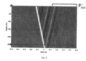
- FIG. 5 shows Marchenko redatuming up-going results
- FIG. 6 shows Marchenko redatuming down-going results from the 1D numerical example.
- FIG. 7 shows wavefields at depth after Marchenko redatuming corresponding to the triangles at about 150m and 250m depth in FIG. 4 .
- the retrieved down- and up-going wavefields at the top triangle i.e., at 150m
- the retrieved down- and up-going wavefields at the bottom triangle i.e., at 250 m
- the dotted lines in panels 701 and 703 are the fields used in Fin,0, as required in Equation 2 for example.
- FIG. 8 shows true reflection (panel 801) and true transmission (panel 802) responses of the target layer (dotted line) in FIG. 4 , for a source at the triangle placed at 150m and a receiver placed at the other triangle at 250m depth.
- FIG. 9 shows target reflection responses estimated by TEEI inversion in the example of 1D implementation, benchmarked against the true responses here shown in black (from FIG. 8 ).
- the green lines correspond to a Tikhonov-regularized least-squares inversion of the full TEEI system.
- the PSF-based TEEI responses are obtained without any regularization.
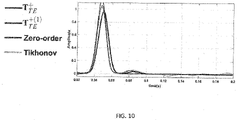
- FIG. 10 shows target transmission responses estimated by TEEI inversion in the example of 1D implementation, benchmarked against the true responses here shown in black (from FIG. 8 ).
- the green lines correspond to a Tikhonov-regularized least-squares inversion of the full TEEI system.
- the PSF-based TEEI responses are obtained without any regularization.
- the methods of the present disclosure have been described in the context of seismic imaging, the methods of the present disclosure also may be used in any industry that relies on back-scattered waves for imaging purposes. This includes medical imaging, engineering, or defense industries as examples. Applications may be for example ultrasound imaging for medical or engineering purposes, radar imaging, or sonar imaging.
- a processor can include a microprocessor, microcontroller, processor module or subsystem, programmable integrated circuit, programmable gate array, graphics processing unit, or another control or computing device, for example.
- Data and instructions may be stored in respective storage devices implemented as one or multiple computer-readable or machine-readable storage media.
- the storage media may include different forms of memory including semiconductor memory devices such as dynamic or static random access memories (DRAMs or SRAMs), erasable and programmable read-only memories (EPROMs), electrically erasable and programmable read-only memories (EEPROMs) and flash memories; magnetic disks such as fixed, floppy and removable disks; other magnetic media including tape; optical media such as compact disks (CDs) or digital video disks (DVDs); or other types of storage devices.
- DRAMs or SRAMs dynamic or static random access memories
- EPROMs erasable and programmable read-only memories
- EEPROMs electrically erasable and programmable read-only memories
- flash memories such as fixed, floppy and removable disks; other magnetic media including tape; optical media such as compact disks (CDs) or digital video disks (DVDs); or other types of storage devices.
- the instructions discussed above can be provided on one computer-readable or machine-readable storage medium, or alternatively, can be provided on multiple computer-readable or machine-readable storage media distributed in a large system having possibly plural nodes.
- Such computer-readable or machine-readable storage medium or media is (are) considered to be part of an article (or article of manufacture).
- An article or article of manufacture can refer to any manufactured single component or multiple components.
- the storage medium or media can be located either in the machine running the machine-readable instructions, or located at a remote site from which machine-readable instructions can be downloaded over a network for execution.
Landscapes
- Engineering & Computer Science (AREA)
- Remote Sensing (AREA)
- Physics & Mathematics (AREA)
- Life Sciences & Earth Sciences (AREA)
- Acoustics & Sound (AREA)
- Environmental & Geological Engineering (AREA)
- Geology (AREA)
- General Life Sciences & Earth Sciences (AREA)
- General Physics & Mathematics (AREA)
- Geophysics (AREA)
- Geophysics And Detection Of Objects (AREA)
Description
- This section is intended to introduce the reader to various aspects of art that may be related to various aspects of the presently described embodiments. This discussion is believed to be helpful in providing the reader with background information to facilitate a better understanding of the various aspects of the described embodiments. Accordingly, it should be understood that these statements are to be read in this light and not as admissions of prior art.
- The present disclosure relates to computer imaging for simulation of physical objects and their interactions. In particular, but not by way of limitation, this disclosure relates to generating Target-Enclosing Extended Image (TEEI) gathers. Reflectivity gathers such as TEEI gathers can be extracted at depth by means of multidimensional deconvolution (MDD). However, local reflectivity inversion by MDD can only retrieve reflection responses at one target datum and, as such, cannot isolate the response of a target volume. For example, while reflectivity inversion may remove interference of overburden structures, interference due to underburden structures may remain.
- Filippo Broggini, "Wave field autofocusing and applications to multidimensional deconvolution and imaging with internal multiples", 1 January 2013, XP055168735 URL:http://ddod.riss.kr/ddodservice/search/viewDetailThesisInfoForm.jsp?p_no=13298926 &p_abstract_yn=Y&p_toc_yn=N&p_fulltext_kind=002&p_search=&p_k2dockey describes a technique involving decomposition of Green's function into downgoing and upgoing components which are used to create ghost-free image of a medium with either cross-correlational or multidimensional deconvolution.
US 2015/046093 describes a method for processing measurements at a datum received by at least one receiver of a wavefield generated by at least one source wherein the wavefield is disturbed by a target, the method comprising receiving at least two sets of measurements of the wavefields affected by the target from the at least one receiver, constructing a Joint Point Spread Function system using the at least two sets of measurements and obtaining reflectivity data by multi-dimensional deconvolution of the Joint Point Spread function system. - The present disclosure relates to TEEI deconvolution. In a first aspect, the present invention resides in a method to generate a seismic image of a subsurface volume of interest through constructing, from surface seismic reflection data, extended image gathers as defined in
claim 1. Preferred embodiments are defined inclaims 2 to 11. The methods of the present disclosure retrieve responses that are devoid of interference due to structures that may exist both above and below the target volume, i.e., the retrieved responses correspond only to the properties of the medium within or inside of the target volume. - By way of non-limiting example only, methods of the present disclosure may include starting with surface reflection data (e.g., surface streamer seismic data, ocean-bottom seismic data, or the like, where the data can be single- or multi-component data) and
- (1) retrieving the up- and down-going fields at two chosen target depth levels by means of Marchenko redatuming.
- (2) using the fields from item (1) to construct an appropriate TEEI system (see for
example Equation 1 below for a field-based TEEI system or Equations 7-8 below for a blurring/Point Spreading Function (PSF)-based TEEI system); and - (3) performing MDD to retrieve the TEEIs from the input fields from item (2), i.e., numerically solving for the block matrix MTE (see, e.g.,
Equation 1 below) that describes the TEEIs. - Retrieval of the TEEIs as described herein overcomes the above limitations of reflectivity-only inversion. Methods of the present disclosure retrieve not only reflection but also transmission responses corresponding to two datums at depth, completely enclosing a target volume e.g. subsurface reservoir, and the retrieved responses are devoid of interference due to structures placed both above and below the target volume.
- For a detailed description of embodiments of the present disclosure, reference will now be made to the accompanying drawings in which:
-
FIGS. 1A and 1B schematically show seismic systems with which one or more embodiments of the present disclosure can be employed; -
FIG. 2 showssteps -
FIG. 3 showssteps -
FIG. 4 shows the constant-wavespeed, variable-density model used in the numerical example of 1D implementation of one or more embodiments of the present disclosure; -
FIG. 5 shows Marchenko redatuming up-going results in the example of 1D implementation of one or more embodiments of the present disclosure; -
FIG. 6 shows Marchenko redatuming down-going results in the example of 1D implementation of one or more embodiments of the present disclosure; -
FIG. 7 shows wavefields at depth after Marchenko redatuming in the example of 1D implementation of one or more embodiments of the present disclosure; -
FIG. 8 shows true reflection and true transmission responses of the target layer in the example of 1D implementation of one or more embodiments of the present disclosure; -
FIG. 9 shows target reflection responses in the example of 1D implementation of one or more embodiments of the present disclosure; and -
FIG. 10 shows target transmission responses in the example of 1D implementation of one or more embodiments of the present disclosure. - Reference will now be made in detail to embodiments, examples of which are illustrated in the accompanying drawings and figures. In the following detailed description, numerous specific details are set forth in order to provide a thorough understanding of the subject matter herein. However, it will be apparent to one of ordinary skill in the art that the subject matter may be practiced without these specific details. In other instances, well-known methods, procedures, components, and systems have not been described in detail so as not to unnecessarily obscure aspects of the embodiments.
- This discussion is directed to various embodiments of the disclosure. The drawing figures are not necessarily to scale. Certain features of the embodiments may be shown exaggerated in scale or in somewhat schematic form, and some details of conventional elements may not be shown in the interest of clarity and conciseness. Although one or more of these embodiments may be preferred, the embodiments disclosed should not be interpreted, or otherwise used, as limiting the scope of the disclosure, the scope of which is to be determined by the appended claims. It is to be fully recognized that the different teachings of the embodiments discussed may be employed separately or in any suitable combination to produce desired results. In addition, one skilled in the art will understand that the description has broad application and that the discussion of any embodiment is meant only to be exemplary of that embodiment, and not intended to intimate that the scope of the disclosure, including the claims, is limited to that embodiment.
- The terminology used in the description of the disclosure herein is for the purpose of describing particular embodiments only and is not intended to be limiting of the subject matter. When introducing elements of various embodiments of the present disclosure and claims, the articles "a," "an," "the," and "said" are intended to mean that there are one or more of the elements. The term "and/or" as used herein refers to and encompasses any and all possible combinations of one or more of the associated listed items. The terms "comprising," "including," and "having" are used in an open-ended fashion, and thus should be interpreted to mean "including, but not limited to ...."
- As used herein, the term "if" may be construed to mean "when" or "upon" or "in response to determining" or "in response to detecting," depending on the context. Similarly, the phrase "if it is determined" or "if (a stated condition or event) is detected" may be construed to mean "upon determining" or "in response to determining" or "upon detecting (the stated condition or event)" or "in response to detecting (the stated condition or event)," depending on the context.
- Also, it is noted that the embodiments may be described as a process which is depicted as a flowchart, a flow diagram, a data flow diagram, a structure diagram, or a block diagram. Although a flowchart may describe the operations as a sequential process, many of the operations can be performed in parallel or concurrently. In addition, the order of the operations may be re-arranged. A process is terminated when its operations are completed, but could have additional steps not included in the figure. A process may correspond to a method, a function, a procedure, a subroutine, a subprogram, etc. When a process corresponds to a function, its termination corresponds to a return of the function to the calling function or the main function.
- Moreover, as disclosed herein, the term "storage medium" may represent one or more devices for storing data, including read only memory (ROM), random access memory (RAM), magnetic RAM, core memory, magnetic disk storage mediums, optical storage mediums, flash memory devices and/or other machine readable mediums for storing information. The term "computer-readable medium" includes, but is not limited to portable or fixed storage devices, optical storage devices, wireless channels and various other mediums capable of storing, containing or carrying instruction(s) and/or data.
- Furthermore, embodiments may be implemented by hardware, software, firmware, middleware, microcode, hardware description languages, or any combination thereof. When implemented in software, firmware, middleware or microcode, the program code or code segments to perform the necessary tasks may be stored in a machine readable medium such as storage medium. A processor(s) may perform the necessary tasks. A code segment may represent a procedure, a function, a subprogram, a program, a routine, a subroutine, a module, a software package, a class, or any combination of instructions, data structures, or program statements. A code segment may be coupled to another code segment or a hardware circuit by passing and/or receiving information, data, arguments, parameters, or memory contents. Information, arguments, parameters, data, etc. may be passed, forwarded, or transmitted via any suitable means including memory sharing, message passing, token passing, network transmission, etc.
- Certain terms are used throughout the description and claims to refer to particular features or components. As one skilled in the art will appreciate, different persons may refer to the same feature or component by different names. This document does not intend to distinguish between components or features that differ in name but not function, unless specifically stated.
- Referring now to the drawings,
FIGS. 1A and 1B schematically illustrate seismic systems with which one or more embodiments of the present disclosure can be employed. The seismic systems are used to perform seismic surveys of Earth formations and subsurface reservoirs. Seismic surveys may be obtained by processing reflected seismic waves (not shown) generated by subsurface seismic reflectors, such as, for example, the top and the bottom of a target reservoir within aformation 4. The reflected seismic waves are typically generated by a seismicacoustic source 1 located at the surface, either on land, as generally and schematically shown inFIG. 1A , or offshore, as generally and schematically shown inFIG. 1B , and received by a receiver orreceiver array 2. When a seismic wave encounters a boundary between two materials having different impedances, a portion of the seismic wave is reflected and a portion of the seismic wave is transmitted through the boundary. - The present disclosure is directed toward using data corresponding to reflected seismic waves at a surface (e.g., the Earth's surface) 4. The methods of the present disclosure generate the so-called Target-Enclosing Extended Image (TEEI) gathers: these are "virtual data" corresponding to waves that are reflected and transmitted only through a target subvolume 7 (e.g., a target reservoir in a formation of
interest 5 in the Earth's interior), as if the target subvolume 7 were completely enclosed by virtual sources and receivers placed both above and below it. While the original surface data contains information related to theentire volume 6 beneath the acquisition surface, the TEEIs of the present disclosure retrieve information that pertains only to a target subvolume 7 with no interference from waves related to structures that lie outside of it. - The methodology of the present disclosure retrieves the TEEIs in two steps: (1) extrapolation or redatuming, and (2) TEEI deconvolution. In the extrapolation or redatuming step, the observed surface reflected seismic waves are recast as if they were recorded inside the medium, though still excited by the original source on the surface. An essential feature of the redatuming step is that it must be able to account for the effects of multiple scattering to enable the retrieval of the TEEIs. According to the invention, this step comprises so-called "Marchenko redatuming" or "Autofocusing."
- In the TEEI deconvolution step, after extrapolation or redatuming, the resulting wave fields at depth are combined into a TEEI block system (see
Equation 1 below), from which the TEEIs are obtained by Multi-Dimensional Deconvolution (MDD). As will be described, the present disclosure presents two embodiments of the MDD solution that yield stable deconvolution solutions and thus stable TEEIs. Equations referred to in the present disclosure are set forth below.





- Referring now to
FIGS. 2 and 3 , example steps of methods of the present disclosure (from original data to end result) are shown. More particularly,FIG. 2 schematically depicts example steps 1 and 2 in accordance with one or more embodiments of the present disclosure: - (1) starting with surface reflection data (e.g., surface streamer seismic data, ocean-bottom seismic data, or the like, where the data can be single- or multi-component data); and
- (2) retrieving the up- and down-going fields at two chosen target depth levels by redatuming, is done by Marchenko redatuming, as it retrieves full-waveform responses at depth, decomposed into up- and down-going components.
-
FIG. 3 schematically depicts example steps 3 and 4 in accordance with one or more embodiments of the present disclosure: - (3) using the fields from step (2) to construct an appropriate TEEI system (see for
example Equation 1 for a field-based TEEI system or Equations 7-8 for a blurring/Point Spreading Function (PSF)-based TEEI system); and - (4) performing MDD to retrieve the TEEIs from the input fields from step (3), i.e., numerically solving for the block matrix MTE that describes the TEEIs.
- In embodiments, step (4) may be done in sub-steps, for example:
- (i) applying an appropriate decomposition given the choice of TEEI system: i.e., either a field-based decomposition (see Equations 2-3), or a PSF/blurring-based decomposition (see Equation 9), noting that matrices [Fin,0] and [Bin,0 = (Fin,0)∗( Fin,0)T] may be calculated by forward modelling using known model parameters (e.g., a migration-velocity model), while [Fin] and [Bin = (Fin)∗( Fin)T] use the total up- and down-going fields resulting from the redatuming step (e.g. Marchenko redatuming);
- (ii) depending on the type of TEEI/solution chosen, estimating the inverse operator of either [Fin,0] or [Bin,0] (denoted with double-dagger superscript in
Equations 4 and 10) by means of any suitable numerical approach, e.g., direct regularized least-squares inverse, iterative gradient-based optimization, sparsity-promoting L1 minimization, or the like; and - (iii) using the matrices from the previous two sub-steps (i) and (ii), calculating the estimate of the TEEI, MTE, to a desired order N, using either the field-based expansion solution (see Equation 4) or the PSF/blurring-based expansion solution (see Equation 10).
- To implement the methods of the present disclosure, a variety of hardware and software may be used. For example, in various embodiments, methods may employ hardware and software to acquire and pre-process the reflection data, e.g., in the case of ocean-bottom seismic, ocean-bottom sensors, source vessels, and the computational and manpower resources to acquire and process the seismic data. Alternatively, such data, e.g., ocean-bottom seismic data in suitable digital format, could be sourced from a third party with the resources to acquire and process the data. Together with the data, a corresponding parameter model suitable for "conventional imaging," e.g. in the case of seismic an industry-standard migration-velocity model, would be required.
- In embodiments, to implement methods of the present disclosure, software in the form of a scripting or programming language with dedicated linear algebra libraries (e.g. C++, JavaScript, Python, MATLAB, or the like) may be used. Additionally or alternatively, specialized software that can execute/perform the redatuming step to the standard required may be used. For example, such specialized software may comprise a set of dedicated computer routines (e.g. written in an example language above) that can take the output data from hardware and/or software used to acquire and pre-process the reflection data and output the input fields by redatuming (according to the invention by Marchenko redatuming).
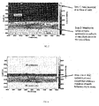
- Embodiments of the presently disclosed methods have been tested in entirety, i.e., starting from surface reflection data, up- and down-going fields were retrieved at two target depth levels by means of Marchenko redatuming, these fields were used as input to construct an appropriate TEEI system and to perform MDD to retrieve the TEEIs. This was done using numerical 1D examples as well as field data, verifying that the method achieves the intended results in a practical and stable fashion. Results are provided in
FIGS. 4-10 . -
FIG. 4 shows results from the constant-wavespeed, variable-density model used in the 1D numerical example. The solid line corresponds to the "true" model, where the desired target layer is indicated by the dashed line. The star and triangle on the left of the graph indicate the location of the zero-offset reflection data, while the triangles at about 150m and 250m depth indicate the datum points for redatuming and for which the TEEI have been extracted. In the example shown, the medium wavespeed is 2000 m/s. -
FIG. 5 shows Marchenko redatuming up-going results, andFIG. 6 shows Marchenko redatuming down-going results from the 1D numerical example. -
FIG. 7 shows wavefields at depth after Marchenko redatuming corresponding to the triangles at about 150m and 250m depth inFIG. 4 . The retrieved down- and up-going wavefields at the top triangle (i.e., at 150m) are shown by the solid lines in the top twopanels panels panels Equation 2 for example. -
FIG. 8 shows true reflection (panel 801) and true transmission (panel 802) responses of the target layer (dotted line) inFIG. 4 , for a source at the triangle placed at 150m and a receiver placed at the other triangle at 250m depth. -
FIG. 9 shows target reflection responses estimated by TEEI inversion in the example of 1D implementation, benchmarked against the true responses here shown in black (fromFIG. 8 ). The green lines correspond to a Tikhonov-regularized least-squares inversion of the full TEEI system. The red lines correspond to the PSF-based expansion, with N = 1, while the blue lines represent the corresponding zero-order (N = 0) terms of the same TEEI expansion. In this embodiment, the PSF-based TEEI responses are obtained without any regularization. -
FIG. 10 shows target transmission responses estimated by TEEI inversion in the example of 1D implementation, benchmarked against the true responses here shown in black (fromFIG. 8 ). The green lines correspond to a Tikhonov-regularized least-squares inversion of the full TEEI system. The red lines correspond to the PSF-based expansion, with N = 1, while the blue lines represent the corresponding zero-order (N = 0) terms of the same TEEI expansion. In this embodiment, the PSF-based TEEI responses are obtained without any regularization. - While the methods of the present disclosure have been described in the context of seismic imaging, the methods of the present disclosure also may be used in any industry that relies on back-scattered waves for imaging purposes. This includes medical imaging, engineering, or defense industries as examples. Applications may be for example ultrasound imaging for medical or engineering purposes, radar imaging, or sonar imaging.
- Machine-readable instructions of steps described above may be loaded for execution on a processor. A processor can include a microprocessor, microcontroller, processor module or subsystem, programmable integrated circuit, programmable gate array, graphics processing unit, or another control or computing device, for example.
- Data and instructions may be stored in respective storage devices implemented as one or multiple computer-readable or machine-readable storage media. The storage media may include different forms of memory including semiconductor memory devices such as dynamic or static random access memories (DRAMs or SRAMs), erasable and programmable read-only memories (EPROMs), electrically erasable and programmable read-only memories (EEPROMs) and flash memories; magnetic disks such as fixed, floppy and removable disks; other magnetic media including tape; optical media such as compact disks (CDs) or digital video disks (DVDs); or other types of storage devices. Note that the instructions discussed above can be provided on one computer-readable or machine-readable storage medium, or alternatively, can be provided on multiple computer-readable or machine-readable storage media distributed in a large system having possibly plural nodes. Such computer-readable or machine-readable storage medium or media is (are) considered to be part of an article (or article of manufacture). An article or article of manufacture can refer to any manufactured single component or multiple components. The storage medium or media can be located either in the machine running the machine-readable instructions, or located at a remote site from which machine-readable instructions can be downloaded over a network for execution.
- Reference throughout this specification to "one embodiment," "an embodiment," or similar language means that a particular feature, structure, or characteristic described in connection with the embodiment may be included in at least one embodiment of the present disclosure. Thus, appearances of the phrases "in one embodiment," "in an embodiment," and similar language throughout this specification may, but do not necessarily, all refer to the same embodiment.
- The foregoing outlines features of several embodiments and sets forth numerous details so that those skilled in the art may better understand the aspects of the present disclosure. Those skilled in the art should appreciate that the present disclosure may provide a basis for designing or modifying other processes and structures for carrying out the same purposes and/or achieving the same advantages of the embodiments introduced herein.
- Although the present disclosure has been described with respect to specific details, it is not intended that such details should be regarded as limitations on the scope of the invention, except to the extent that they are included in the accompanying claims.
Claims (11)
- A computer-implemented method to construct extended image gathers from surface seismic reflection data, the method comprising:retrieving from the surface seismic reflection data up-going and down-going fields at a first target depth level and at a second target depth level by redatuming, wherein the redatuming is accomplished by Marchenko redatuming, the up-going and down-going fields are reflection and transmission responses at the first and second target depth levels and the first and second target depth levels enclose the subsurface volume of interest;using the up-going and down-going fields as input fields to construct a Target-Enclosing Extended Image (TEEI) system comprising TEEI gathers, wherein the TEEI gathers correspond to virtual sources and receivers for retrieving local reflection and local transmission responses at the first and second target depth levels; andperforming multidimensional deconvolution to retrieve the TEEI gathers from the input fields.
- The method of claim 1 wherein the Target-Enclosing Extended Image (TEEI) system is a field-based TEEI system.
- The method of claim 1 wherein the Target-Enclosing Extended Image (TEEI) system is a blurring or Point Spreading Function-based TEEI system.
- The method of claim 1 wherein the performing multidimensional deconvolution comprises numerically solving for a block matrix MTE that describes the TEEI gathers.
- The method of claim 4, wherein the numerically solving for a block matrix MTE that describes the TEEI gathers comprises:(i) selecting and applying a field-based decomposition or a Point Spreading Function or a blurring-based decomposition;(ii) estimating an inverse operator corresponding to the selected decomposition; and(iii) using results from steps (i)-(ii), calculating an estimate of the block matrix MTE to a desired order N using either a field-based expansion solution or a PSF or a blurring-based expansion solution.
- The method of claim 5, wherein in the applying step, the selected matrix decomposition is calculated by one or more of forward modelling using known model parameters and total up-going and down-going fields resulting from the redatuming step.
- The method of claim 6, wherein the forward modelling uses a migration-velocity model.
- The method of claim 5, wherein the inverse operator is estimated using a numerical approach selected from direct regularized least-squares inverse, iterative gradient-based optimization, and sparsity-promoting L1 minimization.
- The method of claim 1, wherein the first target depth level is an original observation datum and the second target depth level is a datum selected to enclose a target volume away from the original observation datum.
- The method of claim 9, wherein the retrieved TEEI gathers correspond only to properties of a medium within the target volume.
- The method of claim 9, wherein the retrieved TEEI gathers are devoid of interference due to structures placed above or below the target volume.
Applications Claiming Priority (2)
| Application Number | Priority Date | Filing Date | Title |
|---|---|---|---|
| US201662382607P | 2016-09-01 | 2016-09-01 | |
| PCT/US2017/049810 WO2018045261A1 (en) | 2016-09-01 | 2017-09-01 | Methods for seismic imaging |
Publications (3)
| Publication Number | Publication Date |
|---|---|
| EP3507624A1 EP3507624A1 (en) | 2019-07-10 |
| EP3507624A4 EP3507624A4 (en) | 2020-04-29 |
| EP3507624B1 true EP3507624B1 (en) | 2023-02-01 |
Family
ID=61301691
Family Applications (1)
| Application Number | Title | Priority Date | Filing Date |
|---|---|---|---|
| EP17847607.3A Active EP3507624B1 (en) | 2016-09-01 | 2017-09-01 | Methods for seismic imaging |
Country Status (3)
| Country | Link |
|---|---|
| US (1) | US10859722B2 (en) |
| EP (1) | EP3507624B1 (en) |
| WO (1) | WO2018045261A1 (en) |
Families Citing this family (5)
| Publication number | Priority date | Publication date | Assignee | Title |
|---|---|---|---|---|
| EP3171203B1 (en) * | 2015-11-18 | 2019-01-02 | CGG Services SAS | Adaptive ensemble-based method and device for highly-nonlinear problems |
| CN114428342A (en) * | 2020-10-10 | 2022-05-03 | 中国石油化工股份有限公司 | Markenko Green function reconstruction method and system based on MPI |
| US20240255666A1 (en) * | 2023-01-27 | 2024-08-01 | Aramco Overseas Company B.V. | Linear-radon-marchenko equation based internal multiple elimination |
| CN120214876A (en) * | 2023-12-26 | 2025-06-27 | 中国石油天然气集团有限公司 | A method and device for reconstructing near-missing seismic data using Marchenko imaging |
| CN118033746B (en) * | 2024-04-07 | 2024-07-09 | 吉林大学 | Object-oriented marine streamer seismic data Marchenko imaging method |
Family Cites Families (10)
| Publication number | Priority date | Publication date | Assignee | Title |
|---|---|---|---|---|
| US8937848B2 (en) * | 2010-07-27 | 2015-01-20 | Cggveritas Services Sa | Methods and systems to eliminate undesirable variations in time-lapse seismic surveys |
| US9176249B2 (en) * | 2011-12-21 | 2015-11-03 | Cggveritas Services Sa | Device and method for processing variable depth streamer data |
| WO2013144847A1 (en) * | 2012-03-27 | 2013-10-03 | Westerngeco Llc | Interferometry-based data redatuming and/or depth imaging |
| US9291737B2 (en) * | 2012-05-31 | 2016-03-22 | Pgs Geophysical As | Methods and systems for imaging subterranean formations with primary and multiple reflections |
| US20140200820A1 (en) * | 2013-01-11 | 2014-07-17 | Westerngeco L.L.C. | Wavefield extrapolation and imaging using single- or multi-component seismic measurements |
| US10036818B2 (en) | 2013-09-06 | 2018-07-31 | Exxonmobil Upstream Research Company | Accelerating full wavefield inversion with nonstationary point-spread functions |
| US9784870B2 (en) | 2013-10-22 | 2017-10-10 | Cgg Services Sas | Demultiple using up/down separation of towed variable-depth streamer data |
| GB2509223B (en) | 2013-10-29 | 2015-03-18 | Imp Innovations Ltd | Method of, and apparatus for, full waveform inversion |
| GB2521598A (en) * | 2013-12-02 | 2015-07-01 | Statoil Petroleum As | Multi-dimensional deconvolution using exact boundary conditions |
| US10156651B2 (en) * | 2015-04-21 | 2018-12-18 | Pgs Geophysical As | Methods and systems to source deghost and source designature marine seismic data |
-
2017
- 2017-09-01 US US15/694,713 patent/US10859722B2/en active Active
- 2017-09-01 WO PCT/US2017/049810 patent/WO2018045261A1/en not_active Ceased
- 2017-09-01 EP EP17847607.3A patent/EP3507624B1/en active Active
Also Published As
| Publication number | Publication date |
|---|---|
| US20180180754A1 (en) | 2018-06-28 |
| US10859722B2 (en) | 2020-12-08 |
| WO2018045261A1 (en) | 2018-03-08 |
| EP3507624A4 (en) | 2020-04-29 |
| EP3507624A1 (en) | 2019-07-10 |
Similar Documents
| Publication | Publication Date | Title |
|---|---|---|
| US10859722B2 (en) | Methods for seismic imaging | |
| US7974824B2 (en) | Seismic inversion of data containing surface-related multiples | |
| US10281604B2 (en) | Method of removing noise in seismic reverse-time migration | |
| US10234581B2 (en) | System and method for high resolution seismic imaging | |
| US9588245B2 (en) | Efficient wavefield extrapolation in anisotropic media | |
| US10215869B2 (en) | System and method of estimating anisotropy properties of geological formations using a self-adjoint pseudoacoustic wave propagator | |
| CA2816492C (en) | System and method for seismic imaging with reduced computational cost | |
| WO2011110917A2 (en) | Processing geophysical data | |
| Brackenhoff et al. | 3D Marchenko applications: Implementation and examples | |
| US10454713B2 (en) | Domain decomposition using a multi-dimensional spacepartitioning tree | |
| Khoshnavaz et al. | Velocity-independent estimation of kinematic attributes in vertical transverse isotropy media using local slopes and predictive painting | |
| Dukalski et al. | Overburden-borne internal demultiple formula | |
| Fernandez et al. | Towards deep learning for seismic demultiple | |
| US10564305B2 (en) | Efficient internal multiple prediction methods | |
| US10353095B2 (en) | System and method for prismatic seismic imaging | |
| AU2016220145B2 (en) | Black hole boundary conditions | |
| EP3387466A1 (en) | Efficient internal multiple prediction methods | |
| Meles et al. | Data‐driven retrieval of primary plane‐wave responses | |
| Dorn | Structurally oriented coherent noise filtering | |
| Shoja et al. | Target-enclosed least-squares seismic imaging | |
| Retailleau et al. | Advanced 3D Land Internal Mutiple Modeling and Subtraction, a WAZ Oman Case Study | |
| Mahgoub et al. | Improved Up-Down Deconvolution in Ultra-Shallow Waters Offshore Abu Dhabi | |
| Hwang et al. | Acoustic full-waveform inversion to match far-offset reflections with pseudo-horizontal particle acceleration data | |
| Al Dhaheri et al. | Innovative data processing QA/QC for the world's largest 3D seismic survey | |
| McLeman et al. | Improved Imaging in Complex Shallow Water Environments via Multi-Parameter FWI Imaging |
Legal Events
| Date | Code | Title | Description |
|---|---|---|---|
| STAA | Information on the status of an ep patent application or granted ep patent |
Free format text: STATUS: THE INTERNATIONAL PUBLICATION HAS BEEN MADE |
|
| PUAI | Public reference made under article 153(3) epc to a published international application that has entered the european phase |
Free format text: ORIGINAL CODE: 0009012 |
|
| STAA | Information on the status of an ep patent application or granted ep patent |
Free format text: STATUS: REQUEST FOR EXAMINATION WAS MADE |
|
| 17P | Request for examination filed |
Effective date: 20190401 |
|
| AK | Designated contracting states |
Kind code of ref document: A1 Designated state(s): AL AT BE BG CH CY CZ DE DK EE ES FI FR GB GR HR HU IE IS IT LI LT LU LV MC MK MT NL NO PL PT RO RS SE SI SK SM TR |
|
| AX | Request for extension of the european patent |
Extension state: BA ME |
|
| DAV | Request for validation of the european patent (deleted) | ||
| DAX | Request for extension of the european patent (deleted) | ||
| A4 | Supplementary search report drawn up and despatched |
Effective date: 20200326 |
|
| RIC1 | Information provided on ipc code assigned before grant |
Ipc: G01V 1/28 20060101AFI20200321BHEP Ipc: G01V 1/36 20060101ALN20200321BHEP Ipc: G01V 1/30 20060101ALI20200321BHEP |
|
| REG | Reference to a national code |
Ref country code: DE Ref legal event code: R079 Ref document number: 602017065911 Country of ref document: DE Free format text: PREVIOUS MAIN CLASS: G01V0001340000 Ipc: G01V0001280000 |
|
| GRAP | Despatch of communication of intention to grant a patent |
Free format text: ORIGINAL CODE: EPIDOSNIGR1 |
|
| RIC1 | Information provided on ipc code assigned before grant |
Ipc: G01V 1/36 20060101ALN20220803BHEP Ipc: G01V 1/30 20060101ALI20220803BHEP Ipc: G01V 1/28 20060101AFI20220803BHEP |
|
| STAA | Information on the status of an ep patent application or granted ep patent |
Free format text: STATUS: GRANT OF PATENT IS INTENDED |
|
| INTG | Intention to grant announced |
Effective date: 20220908 |
|
| GRAS | Grant fee paid |
Free format text: ORIGINAL CODE: EPIDOSNIGR3 |
|
| GRAA | (expected) grant |
Free format text: ORIGINAL CODE: 0009210 |
|
| STAA | Information on the status of an ep patent application or granted ep patent |
Free format text: STATUS: THE PATENT HAS BEEN GRANTED |
|
| AK | Designated contracting states |
Kind code of ref document: B1 Designated state(s): AL AT BE BG CH CY CZ DE DK EE ES FI FR GB GR HR HU IE IS IT LI LT LU LV MC MK MT NL NO PL PT RO RS SE SI SK SM TR |
|
| REG | Reference to a national code |
Ref country code: GB Ref legal event code: FG4D |
|
| REG | Reference to a national code |
Ref country code: CH Ref legal event code: EP Ref country code: AT Ref legal event code: REF Ref document number: 1547063 Country of ref document: AT Kind code of ref document: T Effective date: 20230215 |
|
| REG | Reference to a national code |
Ref country code: DE Ref legal event code: R096 Ref document number: 602017065911 Country of ref document: DE |
|
| REG | Reference to a national code |
Ref country code: IE Ref legal event code: FG4D |
|
| REG | Reference to a national code |
Ref country code: NL Ref legal event code: FP |
|
| REG | Reference to a national code |
Ref country code: LT Ref legal event code: MG9D |
|
| REG | Reference to a national code |
Ref country code: NO Ref legal event code: T2 Effective date: 20230201 |
|
| REG | Reference to a national code |
Ref country code: AT Ref legal event code: MK05 Ref document number: 1547063 Country of ref document: AT Kind code of ref document: T Effective date: 20230201 |
|
| PG25 | Lapsed in a contracting state [announced via postgrant information from national office to epo] |
Ref country code: RS Free format text: LAPSE BECAUSE OF FAILURE TO SUBMIT A TRANSLATION OF THE DESCRIPTION OR TO PAY THE FEE WITHIN THE PRESCRIBED TIME-LIMIT Effective date: 20230201 Ref country code: PT Free format text: LAPSE BECAUSE OF FAILURE TO SUBMIT A TRANSLATION OF THE DESCRIPTION OR TO PAY THE FEE WITHIN THE PRESCRIBED TIME-LIMIT Effective date: 20230601 Ref country code: LV Free format text: LAPSE BECAUSE OF FAILURE TO SUBMIT A TRANSLATION OF THE DESCRIPTION OR TO PAY THE FEE WITHIN THE PRESCRIBED TIME-LIMIT Effective date: 20230201 Ref country code: LT Free format text: LAPSE BECAUSE OF FAILURE TO SUBMIT A TRANSLATION OF THE DESCRIPTION OR TO PAY THE FEE WITHIN THE PRESCRIBED TIME-LIMIT Effective date: 20230201 Ref country code: HR Free format text: LAPSE BECAUSE OF FAILURE TO SUBMIT A TRANSLATION OF THE DESCRIPTION OR TO PAY THE FEE WITHIN THE PRESCRIBED TIME-LIMIT Effective date: 20230201 Ref country code: ES Free format text: LAPSE BECAUSE OF FAILURE TO SUBMIT A TRANSLATION OF THE DESCRIPTION OR TO PAY THE FEE WITHIN THE PRESCRIBED TIME-LIMIT Effective date: 20230201 Ref country code: AT Free format text: LAPSE BECAUSE OF FAILURE TO SUBMIT A TRANSLATION OF THE DESCRIPTION OR TO PAY THE FEE WITHIN THE PRESCRIBED TIME-LIMIT Effective date: 20230201 |
|
| PG25 | Lapsed in a contracting state [announced via postgrant information from national office to epo] |
Ref country code: SE Free format text: LAPSE BECAUSE OF FAILURE TO SUBMIT A TRANSLATION OF THE DESCRIPTION OR TO PAY THE FEE WITHIN THE PRESCRIBED TIME-LIMIT Effective date: 20230201 Ref country code: PL Free format text: LAPSE BECAUSE OF FAILURE TO SUBMIT A TRANSLATION OF THE DESCRIPTION OR TO PAY THE FEE WITHIN THE PRESCRIBED TIME-LIMIT Effective date: 20230201 Ref country code: IS Free format text: LAPSE BECAUSE OF FAILURE TO SUBMIT A TRANSLATION OF THE DESCRIPTION OR TO PAY THE FEE WITHIN THE PRESCRIBED TIME-LIMIT Effective date: 20230601 Ref country code: GR Free format text: LAPSE BECAUSE OF FAILURE TO SUBMIT A TRANSLATION OF THE DESCRIPTION OR TO PAY THE FEE WITHIN THE PRESCRIBED TIME-LIMIT Effective date: 20230502 Ref country code: FI Free format text: LAPSE BECAUSE OF FAILURE TO SUBMIT A TRANSLATION OF THE DESCRIPTION OR TO PAY THE FEE WITHIN THE PRESCRIBED TIME-LIMIT Effective date: 20230201 |
|
| PG25 | Lapsed in a contracting state [announced via postgrant information from national office to epo] |
Ref country code: SM Free format text: LAPSE BECAUSE OF FAILURE TO SUBMIT A TRANSLATION OF THE DESCRIPTION OR TO PAY THE FEE WITHIN THE PRESCRIBED TIME-LIMIT Effective date: 20230201 Ref country code: RO Free format text: LAPSE BECAUSE OF FAILURE TO SUBMIT A TRANSLATION OF THE DESCRIPTION OR TO PAY THE FEE WITHIN THE PRESCRIBED TIME-LIMIT Effective date: 20230201 Ref country code: EE Free format text: LAPSE BECAUSE OF FAILURE TO SUBMIT A TRANSLATION OF THE DESCRIPTION OR TO PAY THE FEE WITHIN THE PRESCRIBED TIME-LIMIT Effective date: 20230201 Ref country code: DK Free format text: LAPSE BECAUSE OF FAILURE TO SUBMIT A TRANSLATION OF THE DESCRIPTION OR TO PAY THE FEE WITHIN THE PRESCRIBED TIME-LIMIT Effective date: 20230201 Ref country code: CZ Free format text: LAPSE BECAUSE OF FAILURE TO SUBMIT A TRANSLATION OF THE DESCRIPTION OR TO PAY THE FEE WITHIN THE PRESCRIBED TIME-LIMIT Effective date: 20230201 |
|
| REG | Reference to a national code |
Ref country code: DE Ref legal event code: R097 Ref document number: 602017065911 Country of ref document: DE |
|
| PG25 | Lapsed in a contracting state [announced via postgrant information from national office to epo] |
Ref country code: SK Free format text: LAPSE BECAUSE OF FAILURE TO SUBMIT A TRANSLATION OF THE DESCRIPTION OR TO PAY THE FEE WITHIN THE PRESCRIBED TIME-LIMIT Effective date: 20230201 |
|
| PLBE | No opposition filed within time limit |
Free format text: ORIGINAL CODE: 0009261 |
|
| STAA | Information on the status of an ep patent application or granted ep patent |
Free format text: STATUS: NO OPPOSITION FILED WITHIN TIME LIMIT |
|
| 26N | No opposition filed |
Effective date: 20231103 |
|
| P01 | Opt-out of the competence of the unified patent court (upc) registered |
Effective date: 20231208 |
|
| PG25 | Lapsed in a contracting state [announced via postgrant information from national office to epo] |
Ref country code: SI Free format text: LAPSE BECAUSE OF FAILURE TO SUBMIT A TRANSLATION OF THE DESCRIPTION OR TO PAY THE FEE WITHIN THE PRESCRIBED TIME-LIMIT Effective date: 20230201 |
|
| REG | Reference to a national code |
Ref country code: DE Ref legal event code: R119 Ref document number: 602017065911 Country of ref document: DE |
|
| REG | Reference to a national code |
Ref country code: CH Ref legal event code: PL |
|
| PG25 | Lapsed in a contracting state [announced via postgrant information from national office to epo] |
Ref country code: LU Free format text: LAPSE BECAUSE OF NON-PAYMENT OF DUE FEES Effective date: 20230901 |
|
| REG | Reference to a national code |
Ref country code: BE Ref legal event code: MM Effective date: 20230930 |
|
| PG25 | Lapsed in a contracting state [announced via postgrant information from national office to epo] |
Ref country code: LU Free format text: LAPSE BECAUSE OF NON-PAYMENT OF DUE FEES Effective date: 20230901 Ref country code: IT Free format text: LAPSE BECAUSE OF FAILURE TO SUBMIT A TRANSLATION OF THE DESCRIPTION OR TO PAY THE FEE WITHIN THE PRESCRIBED TIME-LIMIT Effective date: 20230201 Ref country code: MC Free format text: LAPSE BECAUSE OF FAILURE TO SUBMIT A TRANSLATION OF THE DESCRIPTION OR TO PAY THE FEE WITHIN THE PRESCRIBED TIME-LIMIT Effective date: 20230201 |
|
| REG | Reference to a national code |
Ref country code: IE Ref legal event code: MM4A |
|
| PG25 | Lapsed in a contracting state [announced via postgrant information from national office to epo] |
Ref country code: IE Free format text: LAPSE BECAUSE OF NON-PAYMENT OF DUE FEES Effective date: 20230901 |
|
| PG25 | Lapsed in a contracting state [announced via postgrant information from national office to epo] |
Ref country code: CH Free format text: LAPSE BECAUSE OF NON-PAYMENT OF DUE FEES Effective date: 20230930 |
|
| PG25 | Lapsed in a contracting state [announced via postgrant information from national office to epo] |
Ref country code: IE Free format text: LAPSE BECAUSE OF NON-PAYMENT OF DUE FEES Effective date: 20230901 Ref country code: DE Free format text: LAPSE BECAUSE OF NON-PAYMENT OF DUE FEES Effective date: 20240403 Ref country code: CH Free format text: LAPSE BECAUSE OF NON-PAYMENT OF DUE FEES Effective date: 20230930 |
|
| PG25 | Lapsed in a contracting state [announced via postgrant information from national office to epo] |
Ref country code: BE Free format text: LAPSE BECAUSE OF NON-PAYMENT OF DUE FEES Effective date: 20230930 |
|
| PG25 | Lapsed in a contracting state [announced via postgrant information from national office to epo] |
Ref country code: BG Free format text: LAPSE BECAUSE OF FAILURE TO SUBMIT A TRANSLATION OF THE DESCRIPTION OR TO PAY THE FEE WITHIN THE PRESCRIBED TIME-LIMIT Effective date: 20230201 |
|
| PG25 | Lapsed in a contracting state [announced via postgrant information from national office to epo] |
Ref country code: BG Free format text: LAPSE BECAUSE OF FAILURE TO SUBMIT A TRANSLATION OF THE DESCRIPTION OR TO PAY THE FEE WITHIN THE PRESCRIBED TIME-LIMIT Effective date: 20230201 |
|
| PG25 | Lapsed in a contracting state [announced via postgrant information from national office to epo] |
Ref country code: CY Free format text: LAPSE BECAUSE OF FAILURE TO SUBMIT A TRANSLATION OF THE DESCRIPTION OR TO PAY THE FEE WITHIN THE PRESCRIBED TIME-LIMIT; INVALID AB INITIO Effective date: 20170901 |
|
| PG25 | Lapsed in a contracting state [announced via postgrant information from national office to epo] |
Ref country code: HU Free format text: LAPSE BECAUSE OF FAILURE TO SUBMIT A TRANSLATION OF THE DESCRIPTION OR TO PAY THE FEE WITHIN THE PRESCRIBED TIME-LIMIT; INVALID AB INITIO Effective date: 20170901 |
|
| PGFP | Annual fee paid to national office [announced via postgrant information from national office to epo] |
Ref country code: NL Payment date: 20250704 Year of fee payment: 9 |
|
| PGFP | Annual fee paid to national office [announced via postgrant information from national office to epo] |
Ref country code: NO Payment date: 20250909 Year of fee payment: 9 |
|
| PGFP | Annual fee paid to national office [announced via postgrant information from national office to epo] |
Ref country code: GB Payment date: 20250703 Year of fee payment: 9 |
|
| PGFP | Annual fee paid to national office [announced via postgrant information from national office to epo] |
Ref country code: FR Payment date: 20250703 Year of fee payment: 9 |
|
| PG25 | Lapsed in a contracting state [announced via postgrant information from national office to epo] |
Ref country code: TR Free format text: LAPSE BECAUSE OF FAILURE TO SUBMIT A TRANSLATION OF THE DESCRIPTION OR TO PAY THE FEE WITHIN THE PRESCRIBED TIME-LIMIT Effective date: 20230201 |