EP3506803B1 - Tiered void cells - Google Patents
Tiered void cells Download PDFInfo
- Publication number
- EP3506803B1 EP3506803B1 EP17859209.3A EP17859209A EP3506803B1 EP 3506803 B1 EP3506803 B1 EP 3506803B1 EP 17859209 A EP17859209 A EP 17859209A EP 3506803 B1 EP3506803 B1 EP 3506803B1
- Authority
- EP
- European Patent Office
- Prior art keywords
- tiered void
- base portion
- tiered
- plunger
- void cell
- Prior art date
- Legal status (The legal status is an assumption and is not a legal conclusion. Google has not performed a legal analysis and makes no representation as to the accuracy of the status listed.)
- Active
Links
Images







Classifications
-
- A—HUMAN NECESSITIES
- A47—FURNITURE; DOMESTIC ARTICLES OR APPLIANCES; COFFEE MILLS; SPICE MILLS; SUCTION CLEANERS IN GENERAL
- A47C—CHAIRS; SOFAS; BEDS
- A47C27/00—Spring, stuffed or fluid mattresses or cushions specially adapted for chairs, beds or sofas
- A47C27/08—Fluid mattresses
- A47C27/10—Fluid mattresses with two or more independently-fillable chambers
-
- A—HUMAN NECESSITIES
- A47—FURNITURE; DOMESTIC ARTICLES OR APPLIANCES; COFFEE MILLS; SPICE MILLS; SUCTION CLEANERS IN GENERAL
- A47C—CHAIRS; SOFAS; BEDS
- A47C23/00—Spring mattresses with rigid frame or forming part of the bedstead, e.g. box springs; Divan bases; Slatted bed bases
- A47C23/002—Spring mattresses with rigid frame or forming part of the bedstead, e.g. box springs; Divan bases; Slatted bed bases with separate resilient support elements, e.g. elastomeric springs arranged in a two-dimensional matrix pattern
-
- A—HUMAN NECESSITIES
- A47—FURNITURE; DOMESTIC ARTICLES OR APPLIANCES; COFFEE MILLS; SPICE MILLS; SUCTION CLEANERS IN GENERAL
- A47C—CHAIRS; SOFAS; BEDS
- A47C27/00—Spring, stuffed or fluid mattresses or cushions specially adapted for chairs, beds or sofas
- A47C27/08—Fluid mattresses
-
- A—HUMAN NECESSITIES
- A47—FURNITURE; DOMESTIC ARTICLES OR APPLIANCES; COFFEE MILLS; SPICE MILLS; SUCTION CLEANERS IN GENERAL
- A47C—CHAIRS; SOFAS; BEDS
- A47C23/00—Spring mattresses with rigid frame or forming part of the bedstead, e.g. box springs; Divan bases; Slatted bed bases
- A47C23/04—Spring mattresses with rigid frame or forming part of the bedstead, e.g. box springs; Divan bases; Slatted bed bases using springs in compression, e.g. coiled
- A47C23/047—Spring mattresses with rigid frame or forming part of the bedstead, e.g. box springs; Divan bases; Slatted bed bases using springs in compression, e.g. coiled incorporating inflatable elements
-
- A—HUMAN NECESSITIES
- A47—FURNITURE; DOMESTIC ARTICLES OR APPLIANCES; COFFEE MILLS; SPICE MILLS; SUCTION CLEANERS IN GENERAL
- A47C—CHAIRS; SOFAS; BEDS
- A47C27/00—Spring, stuffed or fluid mattresses or cushions specially adapted for chairs, beds or sofas
- A47C27/04—Spring, stuffed or fluid mattresses or cushions specially adapted for chairs, beds or sofas with spring inlays
- A47C27/06—Spring inlays or spring units therefor
- A47C27/063—Spring inlays or spring units therefor wrapped or otherwise protected
-
- A—HUMAN NECESSITIES
- A47—FURNITURE; DOMESTIC ARTICLES OR APPLIANCES; COFFEE MILLS; SPICE MILLS; SUCTION CLEANERS IN GENERAL
- A47C—CHAIRS; SOFAS; BEDS
- A47C27/00—Spring, stuffed or fluid mattresses or cushions specially adapted for chairs, beds or sofas
- A47C27/04—Spring, stuffed or fluid mattresses or cushions specially adapted for chairs, beds or sofas with spring inlays
- A47C27/06—Spring inlays or spring units therefor
- A47C27/065—Spring inlays or spring units therefor of special shape
-
- A—HUMAN NECESSITIES
- A47—FURNITURE; DOMESTIC ARTICLES OR APPLIANCES; COFFEE MILLS; SPICE MILLS; SUCTION CLEANERS IN GENERAL
- A47C—CHAIRS; SOFAS; BEDS
- A47C27/00—Spring, stuffed or fluid mattresses or cushions specially adapted for chairs, beds or sofas
- A47C27/08—Fluid mattresses
- A47C27/081—Fluid mattresses of pneumatic type
-
- A—HUMAN NECESSITIES
- A47—FURNITURE; DOMESTIC ARTICLES OR APPLIANCES; COFFEE MILLS; SPICE MILLS; SUCTION CLEANERS IN GENERAL
- A47C—CHAIRS; SOFAS; BEDS
- A47C31/00—Details or accessories for chairs, beds, or the like, not provided for in other groups of this subclass, e.g. upholstery fasteners, mattress protectors, stretching devices for mattress nets
-
- A—HUMAN NECESSITIES
- A61—MEDICAL OR VETERINARY SCIENCE; HYGIENE
- A61G—TRANSPORT, PERSONAL CONVEYANCES, OR ACCOMMODATION SPECIALLY ADAPTED FOR PATIENTS OR DISABLED PERSONS; OPERATING TABLES OR CHAIRS; CHAIRS FOR DENTISTRY; FUNERAL DEVICES
- A61G1/00—Stretchers
- A61G1/013—Stretchers foldable or collapsible
-
- A—HUMAN NECESSITIES
- A61—MEDICAL OR VETERINARY SCIENCE; HYGIENE
- A61G—TRANSPORT, PERSONAL CONVEYANCES, OR ACCOMMODATION SPECIALLY ADAPTED FOR PATIENTS OR DISABLED PERSONS; OPERATING TABLES OR CHAIRS; CHAIRS FOR DENTISTRY; FUNERAL DEVICES
- A61G1/00—Stretchers
- A61G1/04—Parts, details or accessories, e.g. head-, foot-, or like rests specially adapted for stretchers
- A61G1/052—Struts, spars or legs
- A61G1/056—Swivelling legs
- A61G1/0565—Swivelling legs simultaneously folding, e.g. parallelogram structures
- A61G1/0567—Swivelling legs simultaneously folding, e.g. parallelogram structures folding in x-shape
-
- A—HUMAN NECESSITIES
- A61—MEDICAL OR VETERINARY SCIENCE; HYGIENE
- A61G—TRANSPORT, PERSONAL CONVEYANCES, OR ACCOMMODATION SPECIALLY ADAPTED FOR PATIENTS OR DISABLED PERSONS; OPERATING TABLES OR CHAIRS; CHAIRS FOR DENTISTRY; FUNERAL DEVICES
- A61G7/00—Beds specially adapted for nursing; Devices for lifting patients or disabled persons
- A61G7/002—Beds specially adapted for nursing; Devices for lifting patients or disabled persons having adjustable mattress frame
- A61G7/012—Beds specially adapted for nursing; Devices for lifting patients or disabled persons having adjustable mattress frame raising or lowering of the whole mattress frame
-
- A—HUMAN NECESSITIES
- A61—MEDICAL OR VETERINARY SCIENCE; HYGIENE
- A61G—TRANSPORT, PERSONAL CONVEYANCES, OR ACCOMMODATION SPECIALLY ADAPTED FOR PATIENTS OR DISABLED PERSONS; OPERATING TABLES OR CHAIRS; CHAIRS FOR DENTISTRY; FUNERAL DEVICES
- A61G7/00—Beds specially adapted for nursing; Devices for lifting patients or disabled persons
- A61G7/002—Beds specially adapted for nursing; Devices for lifting patients or disabled persons having adjustable mattress frame
- A61G7/015—Beds specially adapted for nursing; Devices for lifting patients or disabled persons having adjustable mattress frame divided into different adjustable sections, e.g. for Gatch position
-
- A—HUMAN NECESSITIES
- A61—MEDICAL OR VETERINARY SCIENCE; HYGIENE
- A61G—TRANSPORT, PERSONAL CONVEYANCES, OR ACCOMMODATION SPECIALLY ADAPTED FOR PATIENTS OR DISABLED PERSONS; OPERATING TABLES OR CHAIRS; CHAIRS FOR DENTISTRY; FUNERAL DEVICES
- A61G7/00—Beds specially adapted for nursing; Devices for lifting patients or disabled persons
- A61G7/002—Beds specially adapted for nursing; Devices for lifting patients or disabled persons having adjustable mattress frame
- A61G7/018—Control or drive mechanisms
-
- B—PERFORMING OPERATIONS; TRANSPORTING
- B23—MACHINE TOOLS; METAL-WORKING NOT OTHERWISE PROVIDED FOR
- B23P—METAL-WORKING NOT OTHERWISE PROVIDED FOR; COMBINED OPERATIONS; UNIVERSAL MACHINE TOOLS
- B23P19/00—Machines for simply fitting together or separating metal parts or objects, or metal and non-metal parts, whether or not involving some deformation; Tools or devices therefor so far as not provided for in other classes
- B23P19/04—Machines for simply fitting together or separating metal parts or objects, or metal and non-metal parts, whether or not involving some deformation; Tools or devices therefor so far as not provided for in other classes for assembling or disassembling parts
-
- F—MECHANICAL ENGINEERING; LIGHTING; HEATING; WEAPONS; BLASTING
- F16—ENGINEERING ELEMENTS AND UNITS; GENERAL MEASURES FOR PRODUCING AND MAINTAINING EFFECTIVE FUNCTIONING OF MACHINES OR INSTALLATIONS; THERMAL INSULATION IN GENERAL
- F16F—SPRINGS; SHOCK-ABSORBERS; MEANS FOR DAMPING VIBRATION
- F16F3/00—Spring units consisting of several springs, e.g. for obtaining a desired spring characteristic
- F16F3/08—Spring units consisting of several springs, e.g. for obtaining a desired spring characteristic with springs made of a material having high internal friction, e.g. rubber
- F16F3/087—Units comprising several springs made of plastics or the like material
- F16F3/0873—Units comprising several springs made of plastics or the like material of the same material or the material not being specified
- F16F3/0876—Units comprising several springs made of plastics or the like material of the same material or the material not being specified and of the same shape
Definitions
- Cushioning systems are used in a wide variety of applications including comfort and impact protection of the human body.
- a cushioning system can be placed under a portion of the body and provides protection, comfort and stability.
- a pocketed spring mattress contains an array of close-coupled metal springs that cushion the body from a bed frame.
- footwear, chairs, couches, etc. may each include a cushioning system that provides a barrier between a portion of the body and one or more objects.
- a variety of structures are used for cushioning systems.
- an array of close-coupled, closed-cell air and/or water chambers often constitutes air and water mattresses.
- An array of close-coupled, helical, metallic springs often constitutes a conventional mattress.
- Further examples include open or closed cell foam and elastomeric honeycomb structures.
- US 2003 221336 discloses a material with a substrate and a plurality of compressible connections.
- DE 20 2006 012598 discloses a spring element in the form of rubber-elastic bellows.
- US 2016 166076 discloses a pocketed spring assembly comprising a plurality of parallel interior strings of individually pocketed coil springs.
- a cushioning system according to claim 1 According to the invention there is provided a tiered void cell according to claim 6. According to the invention there is provided a method of using a cushioning system according to claim 12.
- Implementations described and claimed herein include a cushioning system comprising an array of tiered void cells, wherein each tiered void cell includes a base portion, a plunger portion, the plunger portion to collapse into the base portion under compression of the cushioning system, and a living hinge elastically connecting an inner perimeter of the base portion to an outer perimeter of the plunger portion.
- the disclosed technology includes tiered void cells which provide protection, comfort, and stability during compression.
- the tiered void cells may be arranged in vertically stacked columns and include a stroke whereby tiers of a void cell can telescope into adjacent tiers of that void cell, as well as telescope into adjacent tiers of adjacent void cells in a column.
- the tired void cells may be stacked in columns in the same or in different directions, and the stacks of tiered void cells may include void cells of varying numbers of tiers, footprint, size, and materials.
- the tiered void cells may provide different strokes at different parts of a stacked column, and different strokes from a neighboring stack or array of tiered void cells in a cushioning system.
- the tiered void cells may be incorporated into a variety of cushioning systems, including mattresses and seating.
- FIG. 1 illustrates a perspective view of example stacked tiered void cells (e.g., void cells 100, also shown in an exploded View A) in a mattress 160.
- the tiered void cells 100 are molded into vertically stacked columns 168 in an array 166.
- two-tiered void cells 100 e.g., void cell 100a and void cell 100b
- Each tiered void cell in View A comprises a base portion 106 and a plunger portion 108.
- a "tier” may be a defined as a level, a step, or a row of a void cell structure.
- a “tiered void cell” may be defined as a void cell including more than one tier.
- a base portion constitutes a tier and a plunger portion constitutes a tier.
- each tiered void cell in View A has a base portion 106 and a plunger portion 108, each tiered void cell has two tiers.
- a void cell may have more than two tiers.
- a void cell may have three tiers, which includes two base portions and a plunger portion.
- a void cell may have four tiers, which includes three base portions and a plunger portion, and so on. The number of tiers can impact the collapsibility and stroke of the tiered void cell.
- the tiers of the tiered void cells 100 may have differently sized perimeters, and upon compression, tiers with smaller perimeters may collapse with the walls of the tiers with larger perimeters.
- the base portions 106a and 106b and the plunger portions 108a and 108b of each of the tiered void cells 100 have a square opening with a trapezoidal prism volume.
- the plunger portions 108a and 108b may have top surfaces 114a and 114b, and the top surfaces 114a and 114b may or may not have a dome.
- the plunger portions 108a and 108b of each of the tiered void cells 100 have a rounded top surface 114 and do not have a dome.
- the plunger portions 108a and 108b may have other shaped openings, volumes, and top surfaces.
- the base portions 106a and 106b and the plunger portions 108a and 108b can be attached via a variety of components, such as a living hinge 110 (e.g., a connector, a channel, a trough, a chamfer, a step, etc.).
- a living hinge 110 e.g., a connector, a channel, a trough, a chamfer, a step, etc.
- the base portions 106a and 106b and the plunger portions 108 are elastically attached via living hinges 110a and 110b located between the top perimeter of the base portions 106a and 106b and the bottom perimeter of the plunger portions 108a and 108b.
- the living hinges 110a and 110b may range in size.
- the living hinges 110a and 110b can have a significant depth or substantially little to no depth.
- the depth and width of a living hinges 110a and 110b may vary, and the dimensions of the living hinges 110a and 100b contribute to or define the
- the living hinges 110a and 110b of each tiered void cell 100 may be constructed with the same potential materials as the tiered void cells 100 (listed above) and/or different potential materials (e.g., plastics, textiles, metal screens, etc.). Further, the living hinges 110a and 110b may be a solid sheet, woven mesh, or perforated sheet. In mesh or perforated sheet implementations, the living hinges 110a and 110b may act to link the tiered void cells 100 together while allowing fluid flow through the living hinge 110a and 110b.
- living hinges 110a and 110b may be attached to plunging portions 108a and 108b or base portions 106a and 106b via permanent and/or removable connections (e.g., a glued connection, a melted connection, a UV-cured connection, a radio-frequency (RF) welded connection, a laser-welded connection, another welded connection, a sewn connection, and a hook-and-loop connection).
- permanent and/or removable connections e.g., a glued connection, a melted connection, a UV-cured connection, a radio-frequency (RF) welded connection, a laser-welded connection, another welded connection, a sewn connection, and a hook-and-loop connection.
- the two-tiered void cells 100 are shown stacked in opposite directions, with the rounded top surface 114a of one tiered void cell 100a attached to the rounded top surface 114b of the other tiered void cell 100b.
- compressive force may be applied to the tiered void cell 100a.
- the plunger portions 108a and 108b of each of the tiered void cells 100 can collapse or telescope into the base portions 106a and 106b of each tiered void cell, while simultaneously applying compressive force against the plunger portions 108a and 108b of the opposing tiered void cell, by deforming the living hinges 110a and 110b.
- multiple plunger portions collapse (or “plunge") into their respective base portions and against an opposing plunger portion.
- the internal components and geometries of the multiple tiered void cells, such as the multiple plunger portions, define the "spring" mechanism of the column.
- a cushion layer 170 on the mattress 160 may surround the array 166 of void cells 100.
- the cushion layer 170 surrounds the array 166 of void cells 100 on all sides.
- the cushion layer 170 is located only on a top surface or a bottom surface, or only the side surfaces.
- the cushion layer 170 may include a variety of materials (e.g., dense foam, springs, etc.)
- the array 166 of void cells 100 may be implementing inside a cushion layer 170 in a different kind of cushioning system (e.g., a chair), and include other types of cushion layers and configurations. The dimensions of the cushion layer can vary depending on the implementation.
- the array 166 of void cells 100 may be enclosed between a cushion layer 170 in an encasing (e.g., encasing 164).
- the encasing 164 can be made of a variety of materials (e.g., woven textiles, other fabrics, plastics, etc.).
- each vertically stacked column 168 of void cells 100 may have encasing 164 surrounding it.
- the vertical columns 168 can be inserted into the encasing 164 and the encasing 164 can be sealed by a variety of components (e.g., heat sealed) (not shown).
- the tiered void cells 100 are not enclosed and are attached to neighboring void cells 100 in another column 168.
- an elastic material or other flexible material may attach specific void cells 100 in neighboring vertical columns 168 to each other.
- the placement of the attachments between the vertical columns 168 can be varied to impact levels of dependency and moderate compressive force on the tiered void cells 100.
- the vertical column 168 may be affixed to the sides and/or the top and bottom of the encasing 164 or freestanding. Each encasing can be attached to other encasings (e.g., for use in a mattress).
- the height of the vertical column 168 can vary, as well as the number of vertical columns 168. For example, if the vertical column 168 is enclosed in fabric for use in a mattress 160, the vertical column 168 and encasing 164 on the top and bottom of the vertical column 168 may be approximately 20.32 - 30.48 cm (8-12 inches).
- compressive force is applied to an array 166 of void cells 100 or to a specific vertical column 168 of void cells 100.
- the compressive force compresses the rounded top surfaces 114a and 114b of the plunger portions 108a and 108b of the tiered void cells 100a, 100b together.
- the plunger portions 108a and 108b of the tiered void cells 100a, 100b compress (or "plunges") into the base portions 106a and 106b of the tiered void cells 100a, 100b.
- other components of the tiered void cell 100 may compress, and at varying heights.
- the compression can reduce the height of the base portion 106 from 7.62 cm to 1.27 cm (3 inches to 1 ⁇ 2 inch).
- each individual tiered void cell 100 may move independent of an adjacent tiered void cell (not shown).
- the disclosed arrangement of the tiered void cells 100 provides isolation which contributes to distribution of forces and comfort as the tiered void cells 100 support a body, for example.
- the tiered void cells can be individually formed and arranged in a vertical column 168 or an array 166.
- the vertical column 168 or array 166 may arrange void cells 100 either vertically or a horizontally.
- the vertical column 168 or the array 166 of tiered void cells 100 may be a continuous molded structure or sheet.
- the tiered void cells 100 may be hollow chambers that resist a certain amount of deflection due to compressive forces, similar to compression springs. At least the material, wall thickness, size, and shape of each of the tiered void cells 100 define the resistive force that each of the tiered void cells 100 can apply. For example, upon compression on the top surface 114a of the plunger portion 108a of the tiered void cell 100a, the plunger portion 108b can collapse into the base portion 106b of the tiered void cell 100b by deforming the living hinge 110b.
- a living hinge of a void cell controls (substantially promotes or prevents) collapse of a plunger portion into a base portion.
- a living hinge (elastically connecting an inner perimeter of a base portion to an outer perimeter of a plunger portion) stretches according to the invention, causing the plunger portion to collapse into the base portion.
- the rate and depth upon which the plunger portion enters the base portion can vary. Such variables can also influence which tiers the plunger portion may enter.
- the living hinges 110a and 110b can control collapse of the plunger portion 108b of the tiered void cell 100b into the base portion 106b depending on the size, depth, and material of the living hinges 110a and 110b.
- the living hinges 110a and 110b can control collapse of the plunger portion 108a of the tiered void cell 100a into the base portion 106b of the tiered void cell 100b.
- each tier can influence collapsibility of the tiered void cell.
- the opposing base portions 106a and 106b may have a similarly sized perimeter, and during compression of the opposing tiered void cells, although the plunger portions 108a and 108b collapse into adjacent tiers, the opposing base portions 106a and 106b interfere with each other and slow or inhibit collapsibility of the opposing base portions 106a and 106b.
- the tiered void cells 100 may have one or more holes (not shown) through which air or other fluid may pass freely when the tiered void cells 100 are compressed and de-compressed.
- the tiered void cells 100 are fluidly open and communicating with the environment (open to atmosphere).
- the tiered void cells 100 are stacked and there may be venting of the tiered void cells 100 by connecting portions of the tiered void cells 100 to each other via the living hinges 110.
- the tiered void cells 100 can achieve a relatively constant resistance force to deformation.
- the tiered void cells 100 may be closed with sealed air or have engineered air passages to regulated compression.
- the tiered void cells 100 may be filled with ambient air, a fluid other than air, and/or a foam.
- the tiered void cell fill material or fluid may be used to affect the insulating properties of the tiered void cells 100 or the compression characteristics of the individual tiered void cells 100.
- the hollow chambers may remain substantially un-filled.
- Each of the individual void cells may be individually manufactured using a variety of techniques (e.g., blow molding, thermoforming, extrusion, injection molding, laminating, etc.).
- the tiered void cell material is generally elastically deformable under expected load conditions and will withstand numerous deformations without fracturing or suffering other breakdown impairing the function of the tiered void cells 100.
- Example materials include ethylene vinyl acetate (EVA), thermoplastic urethane, thermoplastic elastomers, styrenic co-polymers, rubber, Dow Pellethane®, Lubrizol Estane®, DupontTM Hytrel®, ATOFINA Pebax®, and Krayton polymers.
- the tiered void cell material or certain components of the tiered void cell material may be a solid or less elastomeric material.
- the tiered void cell may be manufactured for a single impact (i.e., one-time use) or manufactured for a single impact under certain predetermined loads.
- the connector of a tiered void cell may be multi-use but the other components of the tiered void cell may be one-time use.
- the wall thickness of each of the tiered void cells may range from 5mil to 250mil. Further, the wall thickness of each of the tiered void cells 100 may be substantially the same (or vary by no more than 10%) over the surface area of each void cell 100. Still further, the size of each of the tiered void cells 100 may range from 5mm to 200mm sides in a cubical implementation. Further yet, the tiered void cells 100 may be cubical, pyramidal, hemispherical, hexagonal, or any other shape capable of having a hollow interior volume. Other shapes may have similar dimensions as the aforementioned cubical implementation. The shape and dimensions of the top surfaces 114a and 114b of each tiered void cell 100 can vary as well. For example, as shown in FIG. 1A , top surfaces 114a and 114b of the tiered void cells 100 are round.
- the tiered void cells 100 may be stacked in a vertical column.
- the tiered void cells 100 can be stacked on top of each other with one or more tiered cells 100 facing a different direction vertically (as shown and described in FIGS. 1 and 6-8 ).
- the tiered void cells 100 may be stacked on top of each other with one or more tiered cells 100 facing the same direction vertically and with one or more tiered cells 100 facing a different direction vertically (as shown and described in FIG. 9 ).
- the tiered void cells 100 may be stacked on top of each other with one or more tiered cells 100 facing the same direction vertically.
- Choice of void cell material, geometry, and/or wall thickness determines the force-deflection characteristics of each void cell 100.
- the individual tiered void cell 100 may be tuned to apply different reaction forces. For example, if a column of tiered void cells 100 is used for a mattress application, a peak load may occur beneath a user's prone or supine body.
- tiered void cells 100 in certain locations may be tuned to deflect under lower force (i.e., have a lower reaction force per unit of deflection) than other tiered void cells 100, as they may be more centrally located near a user's center of gravity.
- Such an arrangement serves to more evenly distribute the user's weight over the entire column of tiered void cells.
- other tiered void cells 100 e.g., tiered void cells located under a user's upper torso or legs
- tiered void cells 100 may be tuned an even higher reaction force per unit of deflection.
- the columns of tiered void cells 100 or an individual void cell 100 themselves are tuned with stiffer cells on or near a perimeter of the column in order to aid centering of a user sitting or lying on the column of tiered void cells 100.
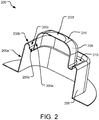
- FIG. 2 illustrates a cross-sectional perspective view of an example tiered void cell 200.
- the tiered void cell 200 in this implementation has two tiers (a base portion 206 and a plunger portion 208).
- the base portion 206 has a square opening with a trapezoidal volume.
- the base portion 206 is attached to a plunger portion 208 via a living hinge 210 located between the upper perimeter of the base portion 206 and the lower perimeter of the plunger portion 208.
- the plunger portion 208 has a square opening with a trapezoidal volume, and a rounded top surface 214.
- the tiered void cells may have one or more tiers, and have tiers with other shaped openings, volumes, and tops.
- the geometries of the disclosed tiered void cells provide cushioning in a liner force/compression relationship without the noise and without the heavy collapse of other geometries that bend and buckle during compression as force is applied.
- the geometries provide stiffness and additional compression results in densification. Further, the geometries of the tiered void cells may be stackable.
- the geometries of the tiered void cells may include interference in the tiered void cell design in collapsibility during compression. For example, during compression of two opposing tiered void cells, if a shoulder (or wall) of a base portion in one tier of a tiered void cell has a similarly sized perimeter of a shoulder of a base portion in the opposing tiered void cell, the shoulders of both opposing base portions may interfere with each other and slow or inhibit collapsibility of those tiers (see FIG. 1 , base portions 106a and 106b have similar sized perimeters and their walls interfere with each other during compression slowing or inhibiting further collapsibility of the tiered void cell). Although some tiers in the opposing tiered void cells may collapse, for example, the plunger portions, the base portions may contact each other and prevent further collapse.
- the geometries of the tiered void cells do not interfere in the tiered void cell design in collapsibility during compression. For example, if the tiers in one void cell have a smaller perimeter than opposing tiers in an adjacent tiered void cell in a stacked column of void cells, then the walls of the tiers in opposing tiered void cells may not interfere with each other during compression (see FIG. 8 , first base portions 806a and 806b and second base portion 822 have different sized perimeters and the walls of those tiers do not interfere with each other.).
- features of the geometry of the tiered void cell 200 are depicted by six walls (or walls). These described walls can be tailored to an intended use and desired compression.
- a first wall 200a is a side wall of the base portion 106 depicted in FIG. 1 .
- the base portion 106 a sphere or square-shaped, has a linear force/compression curve.
- a second wall 200b is a top wall (or shoulder) of the base portion 106 in FIG. 1 .
- the second wall 200b is a horizontal, planar surface. In other implementations, the second wall 200b may be a horizontal, angled surface.
- a third wall 200c is a first side wall of the living hinge 110 in FIG. 1 .
- the third wall 200c is a vertical, planar wall. In other implementations, the third wall 200c may have a vertical, angled surface.
- a fourth wall 200d is a bottom wall of the living hinge 110 in FIG. 1 .
- the fourth wall 200d is a horizontal, planar surface. In other implementations, the fourth wall 200d may have a horizontal, angled surface.
- a fifth wall 200e is a second side wall of the living hinge 110 in FIG. 1 .
- the fifth wall 200e is a vertical, planar surface. In other implementations, the fifth wall 200e may have a vertical, angled surface.
- a sixth wall 200f is a top wall of the plunger portion 108, which can include the top 214 of the plunger portion 208.
- the sixth wall 200f may have a horizontal, planar surface.
- the sixth wall 200f may have a horizontal, angled surface.
- a portion of the sixth wall 200f may be planar and other portions of the sixth wall 200f may be angled.
- the top 114 of the plunger portion 108 may have angled transitions into multiple fifth walls 200e, yet have a horizontal, planar surface across the top surface and no dome.
- the sixth wall 200f may be a radius, which can be a dome.
- the six walls define the shape of the tiered hemi and the rate of collapse and the force needed to collapse a tiered void cell.
- the walls of the second wall 200b, the third wall 200c, the fourth wall 200d, the fifth wall 200e, and the sixth wall 200f of each tier can have the same or different walls and angles defining each tier.
- tiers are not stacked tip to tip or base to base rather the tiers are orientated tip to base with the second wall 200b, the third wall 200c, and the fourth wall 200d between the tiers.
- the overall geometry can then stack with another geometry tip to tip or base to base.
- the geometry of a tiered void cell can collapse in various ways.
- the first wall 200a, the fifth wall 200e, and the sixth wall 200f can buckle.
- the second wall 200b, the third wall 200c, and the fourth wall 200d can rotate.
- the second wall 200b, the third wall 200c, and the fourth wall 200d can stretch.
- a portion of any wall that encounters physical interference with a like portion of a wall in an opposing tier void cell e.g., the second wall or shoulder 200b in a first tiered void cell and the second wall or shoulder 200b in a second tiered void cell prevent further compression of a tiered void cell, and described in FIG. 8 ).
- the order in which the collapsing occurs and the behavior of the tiered void cell due to its geometry is defined by elastic modulus and the buckling force characteristics of each of the walls of the tiered void cells.
- these properties may be defined by raw material type and the thickness of the raw material.
- Various elements influence the behavior of the tiered void cell.
- the spring can be designed to produce very complex force/deflection curves incorporating many different slopes.
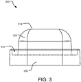
- FIG. 3 illustrates a cross-sectional side view of an example individual tiered void cell 300.
- the tiered void cell 300 in this implementation has two tiers, which comprise a base portion 306 and a plunger portion 308.
- the base portion 306 is attached to a plunger portion 308 via a living hinge 310 located between the upper perimeter of the base portion 306 and the lower perimeter of the plunger portion 307.
- the base portion 306 and the plunger portion 308 have a square opening with a trapezoidal volume.
- the plunger portion 307 has a rounded top 314.
- the tiered void cell 300 may have one or more tiers, and have tiers with other shaped openings, volumes, and tops.
- compressive force may be applied to the top surface 314 of the plunger portion 308 or the bottom surface of the base portion 306, and compress the plunger portion 308 into the base portion 324.
- the living hinge 310 of void cell 300 can control (substantially promote or prevent) collapse of the plunger portion 308 of void cell 300 into the first base portion 306 of void cell 300 depending on its width and depth, for example.
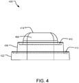
- FIG. 4 illustrates a cross-sectional side view of an example individual tiered void cell 400.
- the tiered void cell 400 in this implementation has three tiers, which comprise a plunger portion 408, a first base portion 406, and a second base portion 422.
- Each tier is attached to a neighboring tier via a living hinge 410 located between the upper perimeter of one tier and the lower perimeter of the neighboring tier.
- a living hinge 410 connecting an inner perimeter of the base portion 406 to an outer perimeter of the plunger portion 408.
- the first base portion 406, the second base portion 422, and the plunger portion 408 each have a square opening with a trapezoidal volume.
- the plunger portion 408 has a rounded top.
- compressive force may be applied to the top surface 414 of the plunger portion 408 or the bottom surface of the second base portion 422, and compress the plunger portion 408 into the first base portion 406 and/or the first base portion 406 into the second base portion 422.
- the living hinges 410 of void cell 400 can control (substantially promote or prevent) collapse of the plunger portion 408 of void cell 400 into the first base portion 406 of void cell 400 and control the collapse of the first base portion 406 into the second base portion 422 depending on their width and depth, for example.
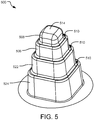
- FIG. 5 illustrates a perspective view of an example tiered void cell 500.
- the tiered void cell 500 in this implementation has four tiers, which comprises a plunger portion 508, a first base portion 506, a second base portion 522, and a third base portion 524.
- Each of the plunger portion 508, the first base portion 506, the second base portion 522, and the third base portion 524 is attached to a neighboring base portion or plunger portion via a living hinge 510.
- a living hinge 510 connecting the outer perimeter of the plunger portion 508 to the inner perimeter of the first base portion 506.
- the plunger portion 508 has a square opening with a trapezoidal volume.
- the plunger portion 508 has a rounded top surface 514.
- compressive force may be applied to the top surface 514 of the plunger portion 508 or the bottom surface of the third base portion 524, and compress the plunger portion 508 into the first base portion 506 and/or the first base portion 506 into the second base portion 522, and/or the second base portion 522 into the third base potion 524.
- the living hinges 510 of void cell 500 can control (substantially promote or prevent) collapse of the plunger portion 508 of void cell 500 into the first base portion 506 of void cell 500, control the collapse of the first base portion 506 into the second base portion 522, and control the collapse of the second base portion 522 into the third base portion 524 depending on their width and depth, for example.
- FIG. 6 illustrates a cross-sectional side view of example stacked tiered void cells 600. Specifically, a two-tiered void cell 600a is shown stacked on top of another two-tiered void cell 600b. The two-tiered void cells 600 are shown stacked in opposite directions, with the rounded top surface 614a of one tiered void cell 600a attached to the rounded top surface 614b of the other tiered void cell 600b.
- the stacked tiered void cells 600 in this implementation each have two tiers, each including a base portion 606a or base portion 606b, and a plunger portion 608a or a plunger portion 608b, respectively.
- the base portions 606a and 606b and the plunger portions 608a and 608b each have a square opening with a trapezoidal volume and are attached to each other via a living hinges 610a and 610b located between the upper perimeter of the base portions 606a and 606b and the lower perimeter of the plunger portions 608a and 608b.
- compressive force may be applied to the base portions 606a and 606b of the tiered void cell 600a and the tiered void cell 600b.
- the plunger portion 608a of the tiered void cell 600a can compress into the base portion 606a of the tiered void cell 600a, while simultaneously applying compressive force against the plunger portion 608b of the tiered void cell 600b.
- the plunger portion 608b of the tiered void cell 600b can collapse into the base portion 606b of the tiered void cell 600b.
- multiple plunger portions compress (or “plunge") into their respective base portions of a void cells as they compress against opposing plunger portions.
- the internal components and geometries of the multiple tiered void cells, such as the multiple plunger portions, define the "spring" mechanism of the column.
- FIG. 7 illustrates a cross-sectional side view of example stacked tiered void cells 700. Specifically, a two-tiered void cell 700a is shown stacked on top of a three-tiered void cell 700b. The tiered void cells 700 are shown stacked in opposite directions, with the bottom perimeter of a base portion 706a of the tiered void cell 700a attached to the bottom perimeter of a second base portion 722 of tiered void cell 700b.
- the plunger portions 708a and 708b of each of the tiered void cells 700 have rounded top surfaces 714a and 714b.
- the plunger portions 708a and 708b, the first base portions 706a and 706b, and the second base portion 722 are attached via living hinges 710a and 710b located between each tier of each of the tiered void cells 700.
- compressive force may be applied to the top surfaces 714a and 714b and compress the plunger portions 708a and 708b into the first base portions 706a and 706b of each of the tiered void cells 700.
- the compressive force may also compress the first base portion 706b into the second base portion 722 of the tiered void cell 700b.
- the living hinges 710a and 710b of tiered void cells 700 can control (substantially promote or prevent) collapse of the plunger portions 708a and 708b of each of the tiered void cells 700 into the first base portions 706a and 706b of each of the tiered void cells 700.
- the living hinge 710b may also control the collapse of the first base portion 706b into the second base portion 722 of the tiered void cell 700b.
- FIG. 8 illustrates a perspective cross-sectional view of example stacked tiered void cells 800. Specifically, a three-tiered void cell is shown stacked on top of a two-tiered void cell 800b. The tiered void cells are shown stacked in opposite directions, with the rounded top surface 814a of one tiered void cell 800a attached to the rounded top surface 814b of the other tiered void cell 800b.
- the plunger portions 808a and 808b of each of the tiered void cells 800 have rounded top surfaces 814a and 814b.
- the plunger portions 808a and 808b, the first base portions 806a and 806b, and the second base portion 822 are attached via living hinges 810a and 810b located between each tier of each of the tiered void cells 800.
- compressive force may be applied to the bottom of the second base portion 822 of the tiered void cell 800a and/or the bottom surface of the first base portion 806b of the tiered void cell 800b, and compress the plunger portions 808a and 808b of each of the tiered void cells 800 into the first base portions 806a and 806b of each of the tiered void cells 800.
- the plunger portions 808a and 808b of each of the tiered void cells 800 may both compress into the first base portion 806b only.
- the compressive force may also compress the first base portion 806a into the second base portion 822, of the tiered void cell 800a.
- the living hinges 810a and 810b of tiered void cells 800 can control (substantially promote or prevent) collapse of the plunger portions 808s and 808b of each of the tiered void cells 800 into the first base portions 806a and 806b of each of the tiered void cells 800.
- the living hinge 810a may also control the collapse of the first base portion 806a into the second base portion 822 of the tiered void cell 800a.
- the compressive force may be applied to the bottom of the second base portion 822 of the tiered void cell 800a and compress the plunger portion 808b of the tiered void cell 800b into the first base portion 806b of the tiered void cell 800b.
- the plunger portion 808a of the tiered void cell 800a also compresses into the first base portion 806b of the tiered void cell 800b.
- the first base portion 806a of the tiered void cell 800a also compresses into the first base portion 806b of the tiered void cell 800b, until the second base portion 822 of the tiered void cell 800a slides past and is adjacent to the first base portion 806b of the tiered void cell 800b.
- the top wall of the second base portion 822 of the tiered void cell 800a may interfere with the top wall of the first base portion 806b of the tiered void cell 800b, slowing or inhibiting further collapse and compression of the stacked void cells.
- FIG. 9 illustrates a cross-sectional side view of example stacked tiered void cells 900.
- two halves of a column of stacked tiered void cells 900 are shown molded together during the manufacturing process.
- the mold is configured for stacked tiered void cells 900 stacked sequentially in opposite direction.
- the plunger portions 908a and 908b of the tiered void cells may be adjacent to opposing plunger portions 908a and 908b.
- the base portions 906a and 906b may be adjacent to opposing base portions 906a and 906b.
- Each of the tiered void cells 900 have two tiers each.
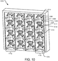
- FIG. 10 illustrates a perspective cross-sectional view of an example stacked tiered void cell array 1000.
- the stacked tiered void cell array 1000 is shaped for an array of four vertically stacked columns 1042. Each column 1042 has seven stacked tiered void cells 1040.
- the tiered void cells 1040 in the stacked tiered void cell array 1000 are stacked in opposite direction, with either a rounded top surface 1014 of one tiered void cell 1040 attached to the rounded top surface 1014 of another tiered void cell 1040 or the opening 1026 at the bottom of one tiered void cell 1040 attached to the opening 1026 at the bottom of another tiered void cell 1040.
- the tiered void cells 1040 are attached at the rounded domes of the rounded tops 1014 of each respective tiered void cell 1040.
- the stacked tiered void cells 1040 in FIG. 10 each have two tiers, each of which comprise a base portion 1006, a plunger portion 1008, and a living hinge 1010.
- the base portion 1006 and the plunger portion 1008 each have a square opening with a trapezoidal volume.
- the base portion 1006 and the plunger portion 1008 are attached via a living hinge 1010.
- the tiered void cells 1040 may have more than two tiers, and may have tiers with other shaped openings, volumes, and tops.
- the columns 1042 of the stacked tiered void cells 1040 may be enclosed by fabric or other material in a housing (e.g., a mattress).
- the columns of stacked tiered void cells 1140 can be glued or otherwise affixed to the fabric or other material.
- FIG. 11A-C illustrate a side perspective view of an example array of stacked tiered void cells 1100 prior to and during compression.
- FIG. 11A illustrates a side view of example stacked tiered void cells 1100 prior to compression.
- two-tiered void cells 1100 are shown stacked, in opposite direction, with a rounded top surface 1114a of the plunger portion 1108a of one void cell 1100a adjacent to a rounded top surface 1114b of the plunger portion 1108b of the other tiered void cell 1100b.
- the stacked tiered void cells in this implementation each have two tiers connected via living hinges 1110a and 1110b located between the tiers.
- a force 1170 is shown that is configured to apply compressive force to the tiered void cell 1100a.
- FIG. 11B illustrates a side view of example stacked tiered void cells during an initial compression mode or initial load deflection (ILD) mode.
- ILD initial load deflection
- FIG. 11B upon compression, compressive force is first applied to the tiered void cell 1100a, as shown.
- the rounded top surfaces 1114a and 1114b of the plunger portions 1108a and 1108b of the tiered void cells 1100 begin to collapse into each other, and into their respective plunger portions 1108a and 1108b, as shown.
- FIG. 11C illustrates a side view of example stacked tiered void cells during compression.
- two-tiered void cells 1100 are shown stacked, in opposite direction, with opposing plunger portions 1108a and 1108b of the tiered void cells 1100 telescoping into their respective base portions 1106a and 1106b.
- the number of tiers and the material can vary, which can impact the compression of the tiered void cells 100. Some void cells 1100 may be more rigid than others. In some implementations where the tiered void cells 1100 are less rigid, there may be rotation of the tiered void cells 1100 stacked against each other, acting as a pressure reliever. In some implementations, varying the number of tiers and the material can vary which tiers telescope into other tiers and at different rates.
- void cell 1100a was a less rigid two-tier void cell, it may telescope in its entirety into a more rigid three-tiered void cell 1100b upon compression, and the more rigid three-tiered void cell 1100b may have less compression within its tiers.
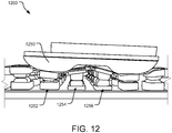
- FIG. 12 illustrates a side perspective view of an example array of stacked tiered void cells 1200 during compression.
- the example array of stacked tiered void cells 1200 six rows of two-tiered void cells are shown stacked in opposite directions, with the rounded top surface of a plunger portion of one tiered void cell attached to the rounded top surface of a plunger portion of another tiered void cell.
- the array 1200 of void cells can be molded from bulk material.
- a common tiered void cell geometry is achieved by reusing a mold or set of molds to produce the individual tiered void cells in the array 1200.
- varying the number of tiers and the material in a void cell stack can impact independence, rotation, flexibility, amount of compressions, and which tiers telescope into other tiers and at different rates, in a cushioning system.
- the shape and weight of a force 1250 can also impact the rotation of a void cell stack.
- a "force" may be defined as a component, apparatus, or object that applies compressive force. For example, if a cushioning system is a seating, and the force 1250 is a person's body sitting on the seating, the distribution of force and weight across a cushioning system may vary.
- a force 1250 may apply compressive force to the tiered void cells 1200.
- Some void cells 1200 may be more rigid than others.
- void cell stacks 1252, 1254, and 1256 show that when the force 1250 compresses the tiered void cell 1200, the tiered void cell stacks 1252, 1254, and 1256 compress at different depths and angles.
- each tier upon compression, when compressive force is applied to each void cell, the plunger portion of each tier can collapse (or "plunge") against an opposing plunger portion of another void cell and into the base portion of each tiered void cell, while simultaneously applying compressive force against the plunger portion of the opposing tiered void cell.
- the plunger portion of each tier can collapse against an opposing plunger portion of another void cell and into the base portion of each tiered void cell by deforming a first living hinge elastically connecting an inner perimeter of the first base portion to an outer perimeter of the first plunger portion.
- Each tiered void cell within the array 1200 may have individual or common force-deflection characteristics.
- a force 1250 elastically collapsing the tiered void cells 1200 may be shaped in a way that when the force 1250 applies compressive force to the tiered void cells 1200, each individual tiered void cell in the array 1200 moves independently of an adjacent tiered void cell (not shown). For example, if the force 1250 was a person sitting on a cushioning system comprising of void cells 1200, there may be different loads applied on different void cells 1200. Therefore, the tiered void cells 1200 may compress in different directions and in different depths.
- the tiered void cell stacks 1252, 1254, and 1256 show side-loading of compressive force (see void cell stacks 1252 and 1256 tilted down toward the right, and void cell stack 1254 tilted down toward the left.
- the disclosed arrangement of the tiered void cells 1200 provides isolation which contributes to distribution of forces and comfort as the tiered void cells support a body, for example.
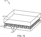
- FIG. 13 illustrates a side perspective view of an example array of stacked tiered void cells in a cushioning system 1300.
- rows or arrays 1360 of two-tiered void cells are shown stacked in opposite directions.
- the cushioning system 1300 may be a mattress or seating apparatus.
- the cushioning system 1300 may have a first cushioning layer 1356 and a second cushioning layer 1358.
- the first cushioning layer 1356 and the second cushioning layer 1358 may vary in sizes and materials, depending on an implementation (e.g., dense foam, springs, etc.). As shown in FIG. 13 , the first cushioning layer 1356 is thicker than the second cushioning layer 1358.
- the first cushioning layer 1356 may be layers of dense foam
- the second cushioning layer 1358 may be springs.
- the first cushioning layer 1356 and the second cushioning layer 1358 may both include dense foam.
- a mattress may include only a first cushioning layer 1356 and stacked tiered void cells.
- FIG. 13 shows the cushioning system 1300 with two stacked tiered void cells, however, in other implementations, there may be a plurality of stacked tiered void cells, as shown in FIG. 1 .
- the stacked void cells may be open or closed, and formed as a sheet or individual, depending on the required independence for the distribution of forces and comfort as the tiered void cells support a body, for example.
- the stacked void cells may be formed as a sheet and the sheet may be cut to an intended implementation.
- the void cells may be formed individually for one layer or array, and formed as a sheet for a second stacked layer or array.
- FIG. 14 illustrates a side view of an example array of stacked tiered void cells in a cushioning system 1400.
- rows or arrays 1460 of two-tiered void cells are shown stacked in opposite directions.
- the cushioning system 1400 may be a mattress or seating apparatus.
- the cushioning system 1400 may have a first cushioning layer 1456 and a second cushioning layer 1458.
- the first cushioning layer 1456 and the second cushioning layer 1458 may vary in sizes and materials, depending on an implementation. As shown in FIG. 14 , the first cushioning layer 1456 is thicker than the second cushioning layer 1458.
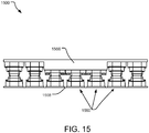
- FIG. 15 illustrates a side view of an example array of stacked tiered void cells in a cushioning system 1500.
- the cushioning system 1500 rows or arrays 1560 of two-tiered void cells are shown stacked in opposite directions.
- the cushioning system 1500 may be a mattress or seating apparatus.
- the cushioning system 1500 may have a first cushioning layer 1556 and a second cushioning layer 1558.
- the first cushioning layer 1556 and the second cushioning layer 1558 may vary in sizes and materials, depending on an implementation. As shown in FIG. 15 , the first cushioning layer 1556 is of varying thickness.
- the first cushioning layer 1556 may have thicker section where additional cushioning layer is required or desired. For example, at least two distinct depths of the cushioning layer may be based on a predetermined support requirement.
- the second cushioning layer 1558 has little to no thickness.
- FIG. 16 illustrates a side view of an example array of stacked tiered void cells in a cushioning system 1600.
- the cushioning system 1600 rows or arrays 1660 of two-tiered void cells are shown stacked in opposite directions.
- the cushioning system 1600 may be a mattress or seating apparatus.
- the cushioning system 1600 may have layers around the rows or arrays 1660 of two-tiered void cells that may be cushioning layers, but in some implementations, may be other materials.
- a first cushioning layer 1656 and a second cushioning layer 1658 are shown.
- the first cushioning layer 1656 and the second cushioning layer 1658 may vary in sizes and materials, depending on an implementation.
- the first cushioning layer 1656 is of varying thickness throughout the cushioning system 1600.
- the first cushioning layer 1656 may have thicker section where additional cushioning layer is required or desired.
- the second cushioning layer 1658 has little to no thickness.
- FIG. 17 is examples operations 1700 for using a cushioning system.
- An operation 1702 applies compressive force to an array of stacked and opposing tiered void cells.
- An operation 1704 collapses a first plunger portion into a first base portion of a tiered void cell by deforming a first living hinge elastically connecting an inner perimeter of the first base portion to an outer perimeter of the first plunger portion.
- An operation 1706 collapses the first base portion into a second base portion of a tiered void cell by deforming a second living hinge elastically connecting an inner perimeter of the second base portion to an outer perimeter of the first base portion.
- An operation 1708 collapses a second plunger portion into a second base portion of a tiered void cell opposing at least one other of the tiered void cells by deforming a second living hinge elastically connecting an inner perimeter of the second base portion to an outer perimeter of the second plunger portion.
- the base portion of the tiered void cell may be compressed into a second base portion of the tiered void cell, if the tiered void cell has more than two tiers.
- the plunger portion of the tiered void cell may be compressed into a second plunger portion of an opposing second tiered void cell.
- the second plunger portion of the second tiered void cell may be compressed into a second base portion of the second tiered void cell.
- a plurality of tiers may telescope within one or both of the tiered void cells.
- the operations 1700 may also include stretching a top wall of the base portion, a first side wall and/or a bottom wall of a living hinge in the tiered void cell.
- other walls in the tiered void cells can stretch, rotate, and buckle.
- at least one of a top wall of the base portion, and the first side wall and the bottom wall of the living hinge may rotate.
- at least one of a side wall of the base portion, a second side wall of the living hinge, and a top wall of the plunger portion may buckle.
Landscapes
- Health & Medical Sciences (AREA)
- Public Health (AREA)
- Life Sciences & Earth Sciences (AREA)
- Animal Behavior & Ethology (AREA)
- General Health & Medical Sciences (AREA)
- Veterinary Medicine (AREA)
- Engineering & Computer Science (AREA)
- Nursing (AREA)
- Mechanical Engineering (AREA)
- General Engineering & Computer Science (AREA)
- Apparatus Associated With Microorganisms And Enzymes (AREA)
- Invalid Beds And Related Equipment (AREA)
- Mattresses And Other Support Structures For Chairs And Beds (AREA)
- Medicines Containing Material From Animals Or Micro-Organisms (AREA)
Description
- The present application claims benefit of priority to
U.S. Provisional Patent Application No. 62/404,969 - Cushioning systems are used in a wide variety of applications including comfort and impact protection of the human body. A cushioning system can be placed under a portion of the body and provides protection, comfort and stability. For example, a pocketed spring mattress contains an array of close-coupled metal springs that cushion the body from a bed frame. Similarly, footwear, chairs, couches, etc. may each include a cushioning system that provides a barrier between a portion of the body and one or more objects.
- A variety of structures are used for cushioning systems. For example, an array of close-coupled, closed-cell air and/or water chambers often constitutes air and water mattresses. An array of close-coupled, helical, metallic springs often constitutes a conventional mattress. Further examples include open or closed cell foam and elastomeric honeycomb structures.
-
US 2003 221336 discloses a material with a substrate and a plurality of compressible connections.DE 20 2006 012598 discloses a spring element in the form of rubber-elastic bellows.US 2016 166076 discloses a pocketed spring assembly comprising a plurality of parallel interior strings of individually pocketed coil springs. - According to the invention there is provided a cushioning system according to claim 1. According to the invention there is provided a tiered void cell according to claim 6. According to the invention there is provided a method of using a cushioning system according to claim 12.
- Implementations described and claimed herein include a cushioning system comprising an array of tiered void cells, wherein each tiered void cell includes a base portion, a plunger portion, the plunger portion to collapse into the base portion under compression of the cushioning system, and a living hinge elastically connecting an inner perimeter of the base portion to an outer perimeter of the plunger portion.
- This Summary is provided to introduce a selection of concepts in a simplified form that are further described below in the Detailed Descriptions. This Summary is not intended to identify key features or essential features of the claimed subject matter, nor is it intended to be used to limit the scope of the claimed subject matter. These and various other features and advantages will be apparent from a reading of the following Detailed Descriptions.
-
-
FIG. 1 illustrates a perspective view of example stacked tiered void cells in a mattress and a detailed view thereof. -
FIG. 2 illustrates a cross-sectional perspective view of an example tiered void cell. -
FIG. 3 illustrates a cross-sectional side view of an example individual tiered void cell. -
FIG. 4 illustrates a cross-sectional side view of another example individual tiered void cell. -
FIG. 5 illustrates a perspective view of another example tiered void cell. -
FIG. 6 illustrates a cross-sectional side view of example stacked tiered void cells. -
FIG. 7 illustrates a cross-sectional side view of example stacked tiered void cells. -
FIG. 8 illustrates a cross-sectional side view of example stacked tiered void cells. -
FIG. 9 illustrates a cross-sectional side view of example stacked tiered void cells. -
FIG. 10 illustrates a perspective cross-sectional view of an stacked tiered void cell array. -
FIG. 11A-C illustrate a side perspective view of an example array of stacked tiered void cells before and during compression. -
FIG. 12 illustrates a side perspective view of an example array of stacked tiered void cells during compression. -
FIG. 13 illustrates a side perspective view of an example array of stacked tiered void cells in a cushioning system. -
FIG. 14 illustrates a side view of an example array of stacked tiered void cells in a cushioning system. -
FIG. 15 illustrates a side view of an example array of stacked tiered void cells in a cushioning system. -
FIG. 16 illustrates a side view of an example array of stacked tiered void cells in a cushioning system. -
FIG. 17 is a flowchart of example operations for using a cushioning system. - The disclosed technology includes tiered void cells which provide protection, comfort, and stability during compression. The tiered void cells may be arranged in vertically stacked columns and include a stroke whereby tiers of a void cell can telescope into adjacent tiers of that void cell, as well as telescope into adjacent tiers of adjacent void cells in a column.
- The tired void cells may be stacked in columns in the same or in different directions, and the stacks of tiered void cells may include void cells of varying numbers of tiers, footprint, size, and materials. The tiered void cells may provide different strokes at different parts of a stacked column, and different strokes from a neighboring stack or array of tiered void cells in a cushioning system. The tiered void cells may be incorporated into a variety of cushioning systems, including mattresses and seating.
-
FIG. 1 illustrates a perspective view of example stacked tiered void cells (e.g.,void cells 100, also shown in an exploded View A) in amattress 160. Thetiered void cells 100 are molded into verticallystacked columns 168 in anarray 166. As shown in View A, two-tiered void cells 100 (e.g.,void cell 100a andvoid cell 100b) may be stacked on top of another. Each tiered void cell in View A comprises a base portion 106 and a plunger portion 108. - For purposes of this disclosure, a "tier" may be a defined as a level, a step, or a row of a void cell structure. A "tiered void cell" may be defined as a void cell including more than one tier. For example, a base portion constitutes a tier and a plunger portion constitutes a tier. Thus, since each tiered void cell in View A has a base portion 106 and a plunger portion 108, each tiered void cell has two tiers. In other implementations, a void cell may have more than two tiers. For example, a void cell may have three tiers, which includes two base portions and a plunger portion. In another example, a void cell may have four tiers, which includes three base portions and a plunger portion, and so on. The number of tiers can impact the collapsibility and stroke of the tiered void cell. In some implementations, the tiers of the
tiered void cells 100 may have differently sized perimeters, and upon compression, tiers with smaller perimeters may collapse with the walls of the tiers with larger perimeters. - Referring to View A, the
base portions plunger portions tiered void cells 100 have a square opening with a trapezoidal prism volume. In some implementations, theplunger portions top surfaces top surfaces FIG. 1 , theplunger portions tiered void cells 100 have a rounded top surface 114 and do not have a dome. In some implementations, theplunger portions - The
base portions plunger portions FIG. 1 , thebase portions base portions plunger portions tiered void cells 100. - In various implementations, the living hinges 110a and 110b of each tiered
void cell 100 may be constructed with the same potential materials as the tiered void cells 100 (listed above) and/or different potential materials (e.g., plastics, textiles, metal screens, etc.). Further, the living hinges 110a and 110b may be a solid sheet, woven mesh, or perforated sheet. In mesh or perforated sheet implementations, the living hinges 110a and 110b may act to link thetiered void cells 100 together while allowing fluid flow through theliving hinge - In some implementations, living hinges 110a and 110b may be attached to plunging
portions base portions - In
FIG. 1 , the two-tiered void cells 100 are shown stacked in opposite directions, with the roundedtop surface 114a of one tieredvoid cell 100a attached to the roundedtop surface 114b of the other tieredvoid cell 100b. - In this implementation, upon compression, compressive force may be applied to the tiered
void cell 100a. Theplunger portions tiered void cells 100 can collapse or telescope into thebase portions plunger portions - In implementations where there are multiple tiered void cells stacked in a column, multiple plunger portions collapse (or "plunge") into their respective base portions and against an opposing plunger portion. The internal components and geometries of the multiple tiered void cells, such as the multiple plunger portions, define the "spring" mechanism of the column.
- A
cushion layer 170 on themattress 160 may surround thearray 166 ofvoid cells 100. In some implementations, thecushion layer 170 surrounds thearray 166 ofvoid cells 100 on all sides. In other implementations, thecushion layer 170 is located only on a top surface or a bottom surface, or only the side surfaces. Thecushion layer 170 may include a variety of materials (e.g., dense foam, springs, etc.) In other implementations, thearray 166 ofvoid cells 100 may be implementing inside acushion layer 170 in a different kind of cushioning system (e.g., a chair), and include other types of cushion layers and configurations. The dimensions of the cushion layer can vary depending on the implementation. - In some implementations, the
array 166 ofvoid cells 100 may be enclosed between acushion layer 170 in an encasing (e.g., encasing 164). The encasing 164 can be made of a variety of materials (e.g., woven textiles, other fabrics, plastics, etc.). In some implementations, each vertically stackedcolumn 168 ofvoid cells 100 may have encasing 164 surrounding it. Thevertical columns 168 can be inserted into the encasing 164 and the encasing 164 can be sealed by a variety of components (e.g., heat sealed) (not shown). In some implementations, thetiered void cells 100 are not enclosed and are attached to neighboringvoid cells 100 in anothercolumn 168. For example, an elastic material or other flexible material, for example, may attach specificvoid cells 100 in neighboringvertical columns 168 to each other. The placement of the attachments between thevertical columns 168 can be varied to impact levels of dependency and moderate compressive force on thetiered void cells 100. - In some implementations, the
vertical column 168 may be affixed to the sides and/or the top and bottom of the encasing 164 or freestanding. Each encasing can be attached to other encasings (e.g., for use in a mattress). The height of thevertical column 168 can vary, as well as the number ofvertical columns 168. For example, if thevertical column 168 is enclosed in fabric for use in amattress 160, thevertical column 168 and encasing 164 on the top and bottom of thevertical column 168 may be approximately 20.32 - 30.48 cm (8-12 inches). - In this implementation, upon compression, compressive force is applied to an
array 166 ofvoid cells 100 or to a specificvertical column 168 ofvoid cells 100. The compressive force compresses the roundedtop surfaces plunger portions tiered void cells plunger portions tiered void cells base portions tiered void cells void cell 100 may compress, and at varying heights. In one implementation, the compression can reduce the height of the base portion 106 from 7.62 cm to 1.27 cm (3 inches to ½ inch). - In an
array 166, each individual tieredvoid cell 100 may move independent of an adjacent tiered void cell (not shown). The disclosed arrangement of thetiered void cells 100 provides isolation which contributes to distribution of forces and comfort as thetiered void cells 100 support a body, for example. - In some implementations, the tiered void cells can be individually formed and arranged in a
vertical column 168 or anarray 166. Thevertical column 168 orarray 166 may arrangevoid cells 100 either vertically or a horizontally. In other implementations, thevertical column 168 or thearray 166 of tieredvoid cells 100 may be a continuous molded structure or sheet. - The
tiered void cells 100 may be hollow chambers that resist a certain amount of deflection due to compressive forces, similar to compression springs. At least the material, wall thickness, size, and shape of each of thetiered void cells 100 define the resistive force that each of thetiered void cells 100 can apply. For example, upon compression on thetop surface 114a of theplunger portion 108a of the tieredvoid cell 100a, theplunger portion 108b can collapse into thebase portion 106b of the tieredvoid cell 100b by deforming theliving hinge 110b. - A living hinge of a void cell according to the invention controls (substantially promotes or prevents) collapse of a plunger portion into a base portion. When a force is applied to a tier in a void cell, a living hinge (elastically connecting an inner perimeter of a base portion to an outer perimeter of a plunger portion) stretches according to the invention, causing the plunger portion to collapse into the base portion. Depending on the size, depth, and material of the living hinge, the rate and depth upon which the plunger portion enters the base portion can vary. Such variables can also influence which tiers the plunger portion may enter.
- For example, upon compression of the
tiered void cells plunger portion 108b of the tieredvoid cell 100b into thebase portion 106b depending on the size, depth, and material of the living hinges 110a and 110b. Similarly, upon compression of thetiered void cells plunger portion 108a of the tieredvoid cell 100a into thebase portion 106b of the tieredvoid cell 100b. - Further, the size of each tier can influence collapsibility of the tiered void cell. As shown in
FIG. 1 , the opposingbase portions plunger portions base portions base portions - The
tiered void cells 100 may have one or more holes (not shown) through which air or other fluid may pass freely when thetiered void cells 100 are compressed and de-compressed. Thetiered void cells 100 are fluidly open and communicating with the environment (open to atmosphere). In some implementations, thetiered void cells 100 are stacked and there may be venting of thetiered void cells 100 by connecting portions of thetiered void cells 100 to each other via the living hinges 110. By not relying on air pressure for resistance to deflection, thetiered void cells 100 can achieve a relatively constant resistance force to deformation. - In another implementation, the
tiered void cells 100 may be closed with sealed air or have engineered air passages to regulated compression. Thetiered void cells 100 may be filled with ambient air, a fluid other than air, and/or a foam. The tiered void cell fill material or fluid may be used to affect the insulating properties of thetiered void cells 100 or the compression characteristics of the individual tieredvoid cells 100. Still further, in a vacuum or near-vacuum environment (e.g., outer space), the hollow chambers may remain substantially un-filled. - Each of the individual void cells may be individually manufactured using a variety of techniques (e.g., blow molding, thermoforming, extrusion, injection molding, laminating, etc.). The tiered void cell material is generally elastically deformable under expected load conditions and will withstand numerous deformations without fracturing or suffering other breakdown impairing the function of the
tiered void cells 100. Example materials include ethylene vinyl acetate (EVA), thermoplastic urethane, thermoplastic elastomers, styrenic co-polymers, rubber, Dow Pellethane®, Lubrizol Estane®, Dupont™ Hytrel®, ATOFINA Pebax®, and Krayton polymers. However, in some implementations, the tiered void cell material or certain components of the tiered void cell material (e.g., the connector) may be a solid or less elastomeric material. For example, the tiered void cell may be manufactured for a single impact (i.e., one-time use) or manufactured for a single impact under certain predetermined loads. In another example, the connector of a tiered void cell may be multi-use but the other components of the tiered void cell may be one-time use. - The wall thickness of each of the tiered void cells may range from 5mil to 250mil. Further, the wall thickness of each of the
tiered void cells 100 may be substantially the same (or vary by no more than 10%) over the surface area of eachvoid cell 100. Still further, the size of each of thetiered void cells 100 may range from 5mm to 200mm sides in a cubical implementation. Further yet, thetiered void cells 100 may be cubical, pyramidal, hemispherical, hexagonal, or any other shape capable of having a hollow interior volume. Other shapes may have similar dimensions as the aforementioned cubical implementation. The shape and dimensions of thetop surfaces void cell 100 can vary as well. For example, as shown inFIG. 1A ,top surfaces tiered void cells 100 are round. - In some implementations, the
tiered void cells 100 may be stacked in a vertical column. Thetiered void cells 100 can be stacked on top of each other with one or moretiered cells 100 facing a different direction vertically (as shown and described inFIGS. 1 and6-8 ). In other implementations, thetiered void cells 100 may be stacked on top of each other with one or moretiered cells 100 facing the same direction vertically and with one or moretiered cells 100 facing a different direction vertically (as shown and described inFIG. 9 ). In other implementations (not shown), thetiered void cells 100 may be stacked on top of each other with one or moretiered cells 100 facing the same direction vertically. - Choice of void cell material, geometry, and/or wall thickness determines the force-deflection characteristics of each
void cell 100. In order to tune the column for a particular application where a varied load distribution is expected to be applied to the column (e.g., on a seat or mattress), the individual tieredvoid cell 100 may be tuned to apply different reaction forces. For example, if a column of tieredvoid cells 100 is used for a mattress application, a peak load may occur beneath a user's prone or supine body. As a result, tieredvoid cells 100 in certain locations (e.g., tiered void cells located under a user's waist or hips) may be tuned to deflect under lower force (i.e., have a lower reaction force per unit of deflection) than other tieredvoid cells 100, as they may be more centrally located near a user's center of gravity. Such an arrangement serves to more evenly distribute the user's weight over the entire column of tiered void cells. Or, other tiered void cells 100 (e.g., tiered void cells located under a user's upper torso or legs) may be tuned with a higher reaction force per unit of deflection, as they are away from the heavier weight of a user's body. Other tiered void cells 100 (e.g., tiered void cells located near the head or feet in a bed) may be tuned an even higher reaction force per unit of deflection. In some implementations, the columns of tieredvoid cells 100 or an individualvoid cell 100 themselves are tuned with stiffer cells on or near a perimeter of the column in order to aid centering of a user sitting or lying on the column of tieredvoid cells 100. -
FIG. 2 illustrates a cross-sectional perspective view of an example tieredvoid cell 200. The tieredvoid cell 200 in this implementation has two tiers (abase portion 206 and a plunger portion 208). Thebase portion 206 has a square opening with a trapezoidal volume. Thebase portion 206 is attached to aplunger portion 208 via aliving hinge 210 located between the upper perimeter of thebase portion 206 and the lower perimeter of theplunger portion 208. Theplunger portion 208 has a square opening with a trapezoidal volume, and a roundedtop surface 214. In another implementation, the tiered void cells may have one or more tiers, and have tiers with other shaped openings, volumes, and tops. - The geometries of the disclosed tiered void cells (e.g., tiered void cell 200) provide cushioning in a liner force/compression relationship without the noise and without the heavy collapse of other geometries that bend and buckle during compression as force is applied. The geometries provide stiffness and additional compression results in densification. Further, the geometries of the tiered void cells may be stackable.
- In some implementations, the geometries of the tiered void cells may include interference in the tiered void cell design in collapsibility during compression. For example, during compression of two opposing tiered void cells, if a shoulder (or wall) of a base portion in one tier of a tiered void cell has a similarly sized perimeter of a shoulder of a base portion in the opposing tiered void cell, the shoulders of both opposing base portions may interfere with each other and slow or inhibit collapsibility of those tiers (see
FIG. 1 ,base portions - In some implementations, the geometries of the tiered void cells do not interfere in the tiered void cell design in collapsibility during compression. For example, if the tiers in one void cell have a smaller perimeter than opposing tiers in an adjacent tiered void cell in a stacked column of void cells, then the walls of the tiers in opposing tiered void cells may not interfere with each other during compression (see
FIG. 8 ,first base portions second base portion 822 have different sized perimeters and the walls of those tiers do not interfere with each other.). - Referring to
FIG. 2 , features of the geometry of the tieredvoid cell 200 are depicted by six walls (or walls). These described walls can be tailored to an intended use and desired compression. - A
first wall 200a is a side wall of the base portion 106 depicted inFIG. 1 . The base portion 106, a sphere or square-shaped, has a linear force/compression curve. - A
second wall 200b is a top wall (or shoulder) of the base portion 106 inFIG. 1 . In one implementation, thesecond wall 200b is a horizontal, planar surface. In other implementations, thesecond wall 200b may be a horizontal, angled surface. - A
third wall 200c is a first side wall of the living hinge 110 inFIG. 1 . In one implementation, thethird wall 200c is a vertical, planar wall. In other implementations, thethird wall 200c may have a vertical, angled surface. - A
fourth wall 200d is a bottom wall of the living hinge 110 inFIG. 1 . In one implementation, thefourth wall 200d is a horizontal, planar surface. In other implementations, thefourth wall 200d may have a horizontal, angled surface. - A
fifth wall 200e is a second side wall of the living hinge 110 inFIG. 1 . In one implementation, thefifth wall 200e is a vertical, planar surface. In other implementations, thefifth wall 200e may have a vertical, angled surface. - A
sixth wall 200f is a top wall of the plunger portion 108, which can include the top 214 of theplunger portion 208. In one implementation, thesixth wall 200f may have a horizontal, planar surface. In another implementation, thesixth wall 200f may have a horizontal, angled surface. In yet another implementation, a portion of thesixth wall 200f may be planar and other portions of thesixth wall 200f may be angled. For example, the top 114 of the plunger portion 108 may have angled transitions into multiplefifth walls 200e, yet have a horizontal, planar surface across the top surface and no dome. In some implementations, thesixth wall 200f may be a radius, which can be a dome. - The six walls (the
first wall 200a, thesecond wall 200b, thethird wall 200c, thefourth wall 200d, thefifth wall 200e, and thesixth wall 200f) and the relationships (including angles) between the walls define the shape of the tiered hemi and the rate of collapse and the force needed to collapse a tiered void cell. - In implementations where the tiered void cell has a geometry with multiple tiers, the walls of the
second wall 200b, thethird wall 200c, thefourth wall 200d, thefifth wall 200e, and thesixth wall 200f of each tier can have the same or different walls and angles defining each tier. - In implementations with multiple tiers, tiers are not stacked tip to tip or base to base rather the tiers are orientated tip to base with the
second wall 200b, thethird wall 200c, and thefourth wall 200d between the tiers. The overall geometry can then stack with another geometry tip to tip or base to base. - During compression, the geometry of a tiered void cell can collapse in various ways. For example, in one implementation, the
first wall 200a, thefifth wall 200e, and thesixth wall 200f can buckle. In another implementation, thesecond wall 200b, thethird wall 200c, and thefourth wall 200d can rotate. In yet another implementation, thesecond wall 200b, thethird wall 200c, and thefourth wall 200d can stretch. - In yet another implementation, in a twin or stacked arrangement, there can be a portion of any wall that encounters physical interference with a like portion of a wall in an opposing tier void cell (e.g., the second wall or
shoulder 200b in a first tiered void cell and the second wall orshoulder 200b in a second tiered void cell prevent further compression of a tiered void cell, and described inFIG. 8 ). - The order in which the collapsing occurs and the behavior of the tiered void cell due to its geometry is defined by elastic modulus and the buckling force characteristics of each of the walls of the tiered void cells. In addition to geometrical relationships of the elements of the spring, these properties may be defined by raw material type and the thickness of the raw material. Various elements influence the behavior of the tiered void cell. The spring can be designed to produce very complex force/deflection curves incorporating many different slopes.
- Details regarding the individually formed tiered void cells (including their geometries and materials), the living hinges, and the assembly of a stacked column of tiered void cells discussed with respect to
FIGS. 1 and2 are applicable to the followingFIGS. 3-17 . -
FIG. 3 illustrates a cross-sectional side view of an example individual tieredvoid cell 300. The tieredvoid cell 300 in this implementation has two tiers, which comprise abase portion 306 and aplunger portion 308. Thebase portion 306 is attached to aplunger portion 308 via aliving hinge 310 located between the upper perimeter of thebase portion 306 and the lower perimeter of the plunger portion 307. Thebase portion 306 and theplunger portion 308 have a square opening with a trapezoidal volume. The plunger portion 307 has a roundedtop 314. In another implementation, the tieredvoid cell 300 may have one or more tiers, and have tiers with other shaped openings, volumes, and tops. - In one implementation, upon compression, compressive force may be applied to the
top surface 314 of theplunger portion 308 or the bottom surface of thebase portion 306, and compress theplunger portion 308 into the base portion 324. The livinghinge 310 ofvoid cell 300 can control (substantially promote or prevent) collapse of theplunger portion 308 ofvoid cell 300 into thefirst base portion 306 ofvoid cell 300 depending on its width and depth, for example. -
FIG. 4 illustrates a cross-sectional side view of an example individual tieredvoid cell 400. The tieredvoid cell 400 in this implementation has three tiers, which comprise aplunger portion 408, afirst base portion 406, and asecond base portion 422. Each tier is attached to a neighboring tier via aliving hinge 410 located between the upper perimeter of one tier and the lower perimeter of the neighboring tier. Specifically, there is aliving hinge 410 connecting an inner perimeter of thebase portion 406 to an outer perimeter of theplunger portion 408. There is aliving hinge 410 connecting the outer perimeter of thefirst base portion 406 to the inner perimeter of thesecond base portion 422. Thefirst base portion 406, thesecond base portion 422, and theplunger portion 408 each have a square opening with a trapezoidal volume. Theplunger portion 408 has a rounded top. - In one implementation, upon compression, compressive force may be applied to the
top surface 414 of theplunger portion 408 or the bottom surface of thesecond base portion 422, and compress theplunger portion 408 into thefirst base portion 406 and/or thefirst base portion 406 into thesecond base portion 422. The living hinges 410 ofvoid cell 400 can control (substantially promote or prevent) collapse of theplunger portion 408 ofvoid cell 400 into thefirst base portion 406 ofvoid cell 400 and control the collapse of thefirst base portion 406 into thesecond base portion 422 depending on their width and depth, for example. -
FIG. 5 illustrates a perspective view of an example tieredvoid cell 500. The tieredvoid cell 500 in this implementation has four tiers, which comprises aplunger portion 508, afirst base portion 506, asecond base portion 522, and athird base portion 524. Each of theplunger portion 508, thefirst base portion 506, thesecond base portion 522, and thethird base portion 524 is attached to a neighboring base portion or plunger portion via aliving hinge 510. Specifically, there is aliving hinge 510 connecting the outer perimeter of theplunger portion 508 to the inner perimeter of thefirst base portion 506. There is aliving hinge 510 connecting the outer perimeter of thefirst base portion 506 to the inner perimeter of thesecond base portion 522. There is aliving hinge 510 connecting the outer perimeter of thesecond base portion 522 to the inner perimeter of thethird base portion 524. Theplunger portion 508, thefirst base portion 506, thesecond base portion 522, and thethird base portion 524 each have a square opening with a trapezoidal volume. Theplunger portion 508 has a roundedtop surface 514. - In one implementation, upon compression, compressive force may be applied to the
top surface 514 of theplunger portion 508 or the bottom surface of thethird base portion 524, and compress theplunger portion 508 into thefirst base portion 506 and/or thefirst base portion 506 into thesecond base portion 522, and/or thesecond base portion 522 into thethird base potion 524. The living hinges 510 ofvoid cell 500 can control (substantially promote or prevent) collapse of theplunger portion 508 ofvoid cell 500 into thefirst base portion 506 ofvoid cell 500, control the collapse of thefirst base portion 506 into thesecond base portion 522, and control the collapse of thesecond base portion 522 into thethird base portion 524 depending on their width and depth, for example. -
FIG. 6 illustrates a cross-sectional side view of example stacked tieredvoid cells 600. Specifically, a two-tieredvoid cell 600a is shown stacked on top of another two-tieredvoid cell 600b. The two-tiered void cells 600 are shown stacked in opposite directions, with the roundedtop surface 614a of one tieredvoid cell 600a attached to the roundedtop surface 614b of the other tieredvoid cell 600b. - The stacked tiered
void cells 600 in this implementation each have two tiers, each including abase portion 606a orbase portion 606b, and aplunger portion 608a or aplunger portion 608b, respectively. Thebase portions plunger portions base portions plunger portions - In one implementation, upon compression, compressive force may be applied to the
base portions void cell 600a and the tieredvoid cell 600b. Theplunger portion 608a of the tieredvoid cell 600a can compress into thebase portion 606a of the tieredvoid cell 600a, while simultaneously applying compressive force against theplunger portion 608b of the tieredvoid cell 600b. Theplunger portion 608b of the tieredvoid cell 600b can collapse into thebase portion 606b of the tieredvoid cell 600b. - In implementations where there are multiple tiered void cells stacked in a column with plunger portions opposing other plunger portions and base portions opposing other base portions, multiple plunger portions compress (or "plunge") into their respective base portions of a void cells as they compress against opposing plunger portions. The internal components and geometries of the multiple tiered void cells, such as the multiple plunger portions, define the "spring" mechanism of the column.
-
FIG. 7 illustrates a cross-sectional side view of example stacked tieredvoid cells 700. Specifically, a two-tieredvoid cell 700a is shown stacked on top of a three-tieredvoid cell 700b. Thetiered void cells 700 are shown stacked in opposite directions, with the bottom perimeter of abase portion 706a of the tieredvoid cell 700a attached to the bottom perimeter of asecond base portion 722 of tieredvoid cell 700b. - The
plunger portions first base portions tiered void cells 700, as well as thesecond base portion 722 of the tieredvoid cell 700b, each have a square opening with a trapezoidal volume. Theplunger portions tiered void cells 700 have roundedtop surfaces plunger portions first base portions second base portion 722 are attached via living hinges 710a and 710b located between each tier of each of thetiered void cells 700. - In one implementation, upon compression, compressive force may be applied to the
top surfaces plunger portions first base portions tiered void cells 700. The compressive force may also compress thefirst base portion 706b into thesecond base portion 722 of the tieredvoid cell 700b. The living hinges 710a and 710b of tieredvoid cells 700 can control (substantially promote or prevent) collapse of theplunger portions tiered void cells 700 into thefirst base portions tiered void cells 700. The livinghinge 710b may also control the collapse of thefirst base portion 706b into thesecond base portion 722 of the tieredvoid cell 700b. -
FIG. 8 illustrates a perspective cross-sectional view of example stacked tieredvoid cells 800. Specifically, a three-tiered void cell is shown stacked on top of a two-tieredvoid cell 800b. The tiered void cells are shown stacked in opposite directions, with the roundedtop surface 814a of one tieredvoid cell 800a attached to the roundedtop surface 814b of the other tieredvoid cell 800b. - The
plunger portions first base portions tiered void cells 800, as well as thesecond base portion 822 of the tieredvoid cell 800b, each have a square opening with a trapezoidal volume. Theplunger portions tiered void cells 800 have roundedtop surfaces plunger portions first base portions second base portion 822 are attached via living hinges 810a and 810b located between each tier of each of thetiered void cells 800. - In one implementation, upon compression, compressive force may be applied to the bottom of the
second base portion 822 of the tieredvoid cell 800a and/or the bottom surface of thefirst base portion 806b of the tieredvoid cell 800b, and compress theplunger portions tiered void cells 800 into thefirst base portions tiered void cells 800. In some implementations, theplunger portions tiered void cells 800 may both compress into thefirst base portion 806b only. The compressive force may also compress thefirst base portion 806a into thesecond base portion 822, of the tieredvoid cell 800a. The living hinges 810a and 810b of tieredvoid cells 800 can control (substantially promote or prevent) collapse of theplunger portions 808s and 808b of each of thetiered void cells 800 into thefirst base portions tiered void cells 800. Theliving hinge 810a may also control the collapse of thefirst base portion 806a into thesecond base portion 822 of the tieredvoid cell 800a. - In some implementations, the compressive force may be applied to the bottom of the
second base portion 822 of the tieredvoid cell 800a and compress theplunger portion 808b of the tieredvoid cell 800b into thefirst base portion 806b of the tieredvoid cell 800b. As compression continues, theplunger portion 808a of the tieredvoid cell 800a also compresses into thefirst base portion 806b of the tieredvoid cell 800b. As compression further continues, thefirst base portion 806a of the tieredvoid cell 800a also compresses into thefirst base portion 806b of the tieredvoid cell 800b, until thesecond base portion 822 of the tieredvoid cell 800a slides past and is adjacent to thefirst base portion 806b of the tieredvoid cell 800b. In some implementations, the top wall of thesecond base portion 822 of the tieredvoid cell 800a may interfere with the top wall of thefirst base portion 806b of the tieredvoid cell 800b, slowing or inhibiting further collapse and compression of the stacked void cells. -
FIG. 9 illustrates a cross-sectional side view of example stacked tieredvoid cells 900. In this implementation, two halves of a column of stacked tieredvoid cells 900 are shown molded together during the manufacturing process. The mold is configured for stacked tieredvoid cells 900 stacked sequentially in opposite direction. Theplunger portions plunger portions base portions base portions tiered void cells 900 have two tiers each. -
FIG. 10 illustrates a perspective cross-sectional view of an example stacked tieredvoid cell array 1000. In this implementation, the stacked tieredvoid cell array 1000 is shaped for an array of four vertically stacked columns 1042. Each column 1042 has seven stacked tiered void cells 1040. The tiered void cells 1040 in the stacked tieredvoid cell array 1000 are stacked in opposite direction, with either a roundedtop surface 1014 of one tiered void cell 1040 attached to the roundedtop surface 1014 of another tiered void cell 1040 or theopening 1026 at the bottom of one tiered void cell 1040 attached to theopening 1026 at the bottom of another tiered void cell 1040. In some implementations where the roundedtop surface 1014 has a rounded dome, the tiered void cells 1040 are attached at the rounded domes of therounded tops 1014 of each respective tiered void cell 1040. - The stacked tiered void cells 1040 in
FIG. 10 each have two tiers, each of which comprise abase portion 1006, aplunger portion 1008, and aliving hinge 1010. Thebase portion 1006 and theplunger portion 1008 each have a square opening with a trapezoidal volume. Thebase portion 1006 and theplunger portion 1008 are attached via aliving hinge 1010. The has a roundedtop surface 1014. In another implementation, the tiered void cells 1040 may have more than two tiers, and may have tiers with other shaped openings, volumes, and tops. - In this implementation, the columns 1042 of the stacked tiered void cells 1040 may be enclosed by fabric or other material in a housing (e.g., a mattress). The columns of stacked
tiered void cells 1140 can be glued or otherwise affixed to the fabric or other material. -
FIG. 11A-C illustrate a side perspective view of an example array of stackedtiered void cells 1100 prior to and during compression.FIG. 11A illustrates a side view of example stackedtiered void cells 1100 prior to compression. In this implementation, two-tiered void cells 1100 are shown stacked, in opposite direction, with a roundedtop surface 1114a of theplunger portion 1108a of onevoid cell 1100a adjacent to a roundedtop surface 1114b of theplunger portion 1108b of the other tieredvoid cell 1100b. The stacked tiered void cells in this implementation each have two tiers connected via living hinges 1110a and 1110b located between the tiers. Aforce 1170 is shown that is configured to apply compressive force to the tieredvoid cell 1100a. -
FIG. 11B illustrates a side view of example stacked tiered void cells during an initial compression mode or initial load deflection (ILD) mode. In this implementation, two-tiered void cells 1100 are shown stacked, in opposite direction, with the roundedtop surface 1114a of theplunger portion 1108a of onevoid cell 1100a adjacent to the roundedtop surface 1114b of theplunger portion 1108b of the other tieredvoid cell 1100b. - In
FIG. 11B , upon compression, compressive force is first applied to the tieredvoid cell 1100a, as shown. The roundedtop surfaces plunger portions tiered void cells 1100 begin to collapse into each other, and into theirrespective plunger portions -
FIG. 11C illustrates a side view of example stacked tiered void cells during compression. In this implementation, two-tiered void cells 1100 are shown stacked, in opposite direction, with opposingplunger portions tiered void cells 1100 telescoping into theirrespective base portions - In some implementations, the number of tiers and the material can vary, which can impact the compression of the
tiered void cells 100. Somevoid cells 1100 may be more rigid than others. In some implementations where thetiered void cells 1100 are less rigid, there may be rotation of thetiered void cells 1100 stacked against each other, acting as a pressure reliever. In some implementations, varying the number of tiers and the material can vary which tiers telescope into other tiers and at different rates. For example, ifvoid cell 1100a was a less rigid two-tier void cell, it may telescope in its entirety into a more rigid three-tieredvoid cell 1100b upon compression, and the more rigid three-tieredvoid cell 1100b may have less compression within its tiers. -
FIG. 12 illustrates a side perspective view of an example array of stackedtiered void cells 1200 during compression. In the example array of stackedtiered void cells 1200, six rows of two-tiered void cells are shown stacked in opposite directions, with the rounded top surface of a plunger portion of one tiered void cell attached to the rounded top surface of a plunger portion of another tiered void cell. - In some implementations, the
array 1200 of void cells can be molded from bulk material. In one implementation, a common tiered void cell geometry is achieved by reusing a mold or set of molds to produce the individual tiered void cells in thearray 1200. - In some implementations, varying the number of tiers and the material in a void cell stack can impact independence, rotation, flexibility, amount of compressions, and which tiers telescope into other tiers and at different rates, in a cushioning system. The shape and weight of a
force 1250 can also impact the rotation of a void cell stack. A "force" may be defined as a component, apparatus, or object that applies compressive force. For example, if a cushioning system is a seating, and theforce 1250 is a person's body sitting on the seating, the distribution of force and weight across a cushioning system may vary. - A
force 1250 may apply compressive force to thetiered void cells 1200. Somevoid cells 1200 may be more rigid than others. In some implementations where thetiered void cells 1200 are less rigid, there may be rotation of thetiered void cells 1200 stacked against each other, acting as a pressure reliever. For example,void cell stacks force 1250 compresses the tieredvoid cell 1200, the tieredvoid cell stacks - In this implementation, upon compression, when compressive force is applied to each void cell, the plunger portion of each tier can collapse (or "plunge") against an opposing plunger portion of another void cell and into the base portion of each tiered void cell, while simultaneously applying compressive force against the plunger portion of the opposing tiered void cell. The internal components and geometries of the multiple tiered void cells, such as the living hinges and multiple plunger portions, define the "spring" mechanism of the column. The plunger portion of each tier can collapse against an opposing plunger portion of another void cell and into the base portion of each tiered void cell by deforming a first living hinge elastically connecting an inner perimeter of the first base portion to an outer perimeter of the first plunger portion. Each tiered void cell within the
array 1200 may have individual or common force-deflection characteristics. - In one implementation, as shown in
FIG. 12 , aforce 1250 elastically collapsing thetiered void cells 1200 may be shaped in a way that when theforce 1250 applies compressive force to thetiered void cells 1200, each individual tiered void cell in thearray 1200 moves independently of an adjacent tiered void cell (not shown). For example, if theforce 1250 was a person sitting on a cushioning system comprising ofvoid cells 1200, there may be different loads applied ondifferent void cells 1200. Therefore, thetiered void cells 1200 may compress in different directions and in different depths. For example, the tieredvoid cell stacks void cell stacks void cell stack 1254 tilted down toward the left. The disclosed arrangement of thetiered void cells 1200 provides isolation which contributes to distribution of forces and comfort as the tiered void cells support a body, for example. -
FIG. 13 illustrates a side perspective view of an example array of stacked tiered void cells in acushioning system 1300. In thecushioning system 1300, rows orarrays 1360 of two-tiered void cells are shown stacked in opposite directions. - In some implementations, the
cushioning system 1300 may be a mattress or seating apparatus. Thecushioning system 1300 may have afirst cushioning layer 1356 and asecond cushioning layer 1358. Thefirst cushioning layer 1356 and thesecond cushioning layer 1358 may vary in sizes and materials, depending on an implementation (e.g., dense foam, springs, etc.). As shown inFIG. 13 , thefirst cushioning layer 1356 is thicker than thesecond cushioning layer 1358. In some implementations, for example in a mattress, thefirst cushioning layer 1356 may be layers of dense foam, and thesecond cushioning layer 1358 may be springs. In another implementation, thefirst cushioning layer 1356 and thesecond cushioning layer 1358 may both include dense foam. In some implementations, there may be afirst cushioning layer 1356 and nosecond cushioning layer 1358. For example, a mattress may include only afirst cushioning layer 1356 and stacked tiered void cells. -
FIG. 13 shows thecushioning system 1300 with two stacked tiered void cells, however, in other implementations, there may be a plurality of stacked tiered void cells, as shown inFIG. 1 . The stacked void cells may be open or closed, and formed as a sheet or individual, depending on the required independence for the distribution of forces and comfort as the tiered void cells support a body, for example. In some implementations, the stacked void cells may be formed as a sheet and the sheet may be cut to an intended implementation. In some implementations, the void cells may be formed individually for one layer or array, and formed as a sheet for a second stacked layer or array. -
FIG. 14 illustrates a side view of an example array of stacked tiered void cells in acushioning system 1400. In thecushioning system 1400, rows orarrays 1460 of two-tiered void cells are shown stacked in opposite directions. - In some implementations, the
cushioning system 1400 may be a mattress or seating apparatus. Thecushioning system 1400 may have afirst cushioning layer 1456 and asecond cushioning layer 1458. Thefirst cushioning layer 1456 and thesecond cushioning layer 1458 may vary in sizes and materials, depending on an implementation. As shown inFIG. 14 , thefirst cushioning layer 1456 is thicker than thesecond cushioning layer 1458. -
FIG. 15 illustrates a side view of an example array of stacked tiered void cells in acushioning system 1500. In thecushioning system 1500, rows orarrays 1560 of two-tiered void cells are shown stacked in opposite directions. - In some implementations, the
cushioning system 1500 may be a mattress or seating apparatus. Thecushioning system 1500 may have afirst cushioning layer 1556 and asecond cushioning layer 1558. Thefirst cushioning layer 1556 and thesecond cushioning layer 1558 may vary in sizes and materials, depending on an implementation. As shown inFIG. 15 , thefirst cushioning layer 1556 is of varying thickness. Thefirst cushioning layer 1556 may have thicker section where additional cushioning layer is required or desired. For example, at least two distinct depths of the cushioning layer may be based on a predetermined support requirement. Thesecond cushioning layer 1558 has little to no thickness. -
FIG. 16 illustrates a side view of an example array of stacked tiered void cells in acushioning system 1600. In thecushioning system 1600, rows orarrays 1660 of two-tiered void cells are shown stacked in opposite directions. - In some implementations, the
cushioning system 1600 may be a mattress or seating apparatus. Thecushioning system 1600 may have layers around the rows orarrays 1660 of two-tiered void cells that may be cushioning layers, but in some implementations, may be other materials. Referring toFIG. 16 , afirst cushioning layer 1656 and asecond cushioning layer 1658 are shown. Thefirst cushioning layer 1656 and thesecond cushioning layer 1658 may vary in sizes and materials, depending on an implementation. As shown inFIG. 16 , thefirst cushioning layer 1656 is of varying thickness throughout thecushioning system 1600. Thefirst cushioning layer 1656 may have thicker section where additional cushioning layer is required or desired. Thesecond cushioning layer 1658 has little to no thickness. -
FIG. 17 isexamples operations 1700 for using a cushioning system. Anoperation 1702 applies compressive force to an array of stacked and opposing tiered void cells. Anoperation 1704 collapses a first plunger portion into a first base portion of a tiered void cell by deforming a first living hinge elastically connecting an inner perimeter of the first base portion to an outer perimeter of the first plunger portion. - An
operation 1706 collapses the first base portion into a second base portion of a tiered void cell by deforming a second living hinge elastically connecting an inner perimeter of the second base portion to an outer perimeter of the first base portion. - An
operation 1708 collapses a second plunger portion into a second base portion of a tiered void cell opposing at least one other of the tiered void cells by deforming a second living hinge elastically connecting an inner perimeter of the second base portion to an outer perimeter of the second plunger portion. - In some implementations, the base portion of the tiered void cell may be compressed into a second base portion of the tiered void cell, if the tiered void cell has more than two tiers. In some implementations, the plunger portion of the tiered void cell may be compressed into a second plunger portion of an opposing second tiered void cell. In some implementations, the second plunger portion of the second tiered void cell may be compressed into a second base portion of the second tiered void cell. Depending on the dimensions and the number of tiers in two opposing tiered void cells, a plurality of tiers may telescope within one or both of the tiered void cells.
- The
operations 1700 may also include stretching a top wall of the base portion, a first side wall and/or a bottom wall of a living hinge in the tiered void cell. During compression, in some implementations, other walls in the tiered void cells can stretch, rotate, and buckle. For example, at least one of a top wall of the base portion, and the first side wall and the bottom wall of the living hinge may rotate. In another example, at least one of a side wall of the base portion, a second side wall of the living hinge, and a top wall of the plunger portion may buckle. - The logical operations making up the embodiments of the invention described herein are referred to variously as operations, steps, objects, or modules. Furthermore, it should be understood that logical operations may be performed in any order, adding or omitting operations as desired, unless explicitly claimed otherwise or a specific order is inherently necessitated by the claim language.
- The above specification, examples, and data provide a complete description of the structure and use of exemplary embodiments of the invention. Since many embodiments of the invention can be made without departing from the scope of the invention, the invention resides in the claims hereinafter appended.
Claims (15)
- A cushioning system (160) comprising:
an array of tiered void cells (166), wherein each tiered void cell includes:a base portion (106);a plunger portion (108), the plunger portion to collapse into the base portion under compression of the cushioning system; anda living hinge (110) elastically connecting an inner perimeter of the base portion to an outer perimeter of the plunger portion, the living hinge to stretch to effect the collapse of the plunger portion into the base portion under compression of the cushioning system. - The cushioning system of claim 1, wherein an elastic modulus and a buckling force of one or more walls of each tiered void cell controls collapsibility of each tiered void cell.
- The cushioning system of any preceding claim, incorporated within at least one of a mattress and a seat.
- The cushioning system of any preceding claim, wherein the array of tiered void cells is stacked vertically in columns, each of the vertical columns are enclosed in an encasing, and the vertical columns are attached to neighboring vertical columns.
- The cushioning system of any preceding claim, further comprising:
a cushioning layer positioned adjacent the array of tiered void cells, wherein the cushioning layer has at least two distinct depths based on a predetermined support requirement. - A tiered void cell (100) comprising:a first base portion (106a);a first plunger (108a) portion to collapse into the first base portion under compression of the tiered void cell;a first living hinge (110a) to elastically connect an inner perimeter of the first base portion to an outer perimeter of the first plunger portion, the first living hinge to stretch to effect the collapse of the first plunger portion into the first base portion under compression of the cushioning system;a second base portion (106b);a second plunger portion (108b) to collapse into the second base portion under compression of the tiered void cell; anda second living hinge (110b) to elastically connect an inner perimeter of the second base portion to an outer perimeter of the second plunger portion, the second living hinge to stretch to effect the collapse of the second plunger portion into the second base portion under compression of the cushioning system, and the first plunger portion attached to and opposing the second plunger portion.
- The tiered void cell of claim 6, further comprising:
a third base portion attached to the first base portion, the first base portion to collapse into the third base portion under compression of the tiered void cell. - The tiered void cell of any one of claims 6-7, wherein an elastic modulus and a buckling force of one or more walls of the tiered void cell controls collapsibility of the tiered void cell.
- The tiered void cell of any one of claims 6-8, the first and second living hinges to one or more of stretch, rotate, and buckle under compression of the tiered void cell.
- The tiered void cell of any one of claims 6-9, the first base portion to meet and collapse against the second base portion under compression of the tiered void cell.
- The tiered void cell of any one of claims 6-10, the first base portion to slide inside the second base portion under compression of the tiered void cell.
- A method of using a cushioning system (1700), the method comprising:applying compressive force to an array of stacked and opposing tiered void cells (1702);
andcollapsing a first plunger portion into a first base portion of at least one of the tiered void cells by stretching a first living hinge elastically connecting an inner perimeter of the first base portion to an outer perimeter of the first plunger portion (1704) under the compressive force. - The method of claim 12, further comprising:
collapsing the first base portion into a second base portion of the at least one tiered void cell by deforming a second living hinge elastically connecting an inner perimeter of the second base portion to an outer perimeter of the first base portion. - The method of claim 12, further comprising:
collapsing a second plunger portion into a second base portion of at least one of the tiered void cells opposing at least one other of the tiered void cells by deforming a second living hinge elastically connecting an inner perimeter of the second base portion to an outer perimeter of the second plunger portion. - The method of any one of claims 12-14, wherein the collapsing operation includes all of:stretching a top wall of the first base portion;stretching a side wall and a bottom wall of the first living hinge;rotating a top wall of the first base portion;rotating a side wall and a bottom wall of the first living hinge;buckling the side wall of the first base portion;buckling a second side wall of the first living hinge; andbuckling a top wall of the first plunger portion.
Priority Applications (2)
| Application Number | Priority Date | Filing Date | Title |
|---|---|---|---|
| EP21182515.3A EP3970566A1 (en) | 2016-10-06 | 2017-10-05 | Tiered void cells |
| PL17859209T PL3506803T3 (en) | 2016-10-06 | 2017-10-05 | Tiered void cells |
Applications Claiming Priority (2)
| Application Number | Priority Date | Filing Date | Title |
|---|---|---|---|
| US201662404969P | 2016-10-06 | 2016-10-06 | |
| PCT/US2017/055407 WO2018067863A1 (en) | 2016-10-06 | 2017-10-05 | Tiered void cells |
Related Child Applications (1)
| Application Number | Title | Priority Date | Filing Date |
|---|---|---|---|
| EP21182515.3A Division EP3970566A1 (en) | 2016-10-06 | 2017-10-05 | Tiered void cells |
Publications (3)
| Publication Number | Publication Date |
|---|---|
| EP3506803A1 EP3506803A1 (en) | 2019-07-10 |
| EP3506803A4 EP3506803A4 (en) | 2020-03-04 |
| EP3506803B1 true EP3506803B1 (en) | 2021-07-14 |
Family
ID=61829480
Family Applications (2)
| Application Number | Title | Priority Date | Filing Date |
|---|---|---|---|
| EP21182515.3A Withdrawn EP3970566A1 (en) | 2016-10-06 | 2017-10-05 | Tiered void cells |
| EP17859209.3A Active EP3506803B1 (en) | 2016-10-06 | 2017-10-05 | Tiered void cells |
Family Applications Before (1)
| Application Number | Title | Priority Date | Filing Date |
|---|---|---|---|
| EP21182515.3A Withdrawn EP3970566A1 (en) | 2016-10-06 | 2017-10-05 | Tiered void cells |
Country Status (11)
| Country | Link |
|---|---|
| US (2) | US10986936B2 (en) |
| EP (2) | EP3970566A1 (en) |
| KR (1) | KR102447270B1 (en) |
| CN (2) | CN114098352A (en) |
| AU (1) | AU2017340766A1 (en) |
| CA (1) | CA3037994A1 (en) |
| ES (1) | ES2890925T3 (en) |
| MX (1) | MX2019003920A (en) |
| PL (1) | PL3506803T3 (en) |
| PT (1) | PT3506803T (en) |
| WO (1) | WO2018067863A1 (en) |
Families Citing this family (9)
| Publication number | Priority date | Publication date | Assignee | Title |
|---|---|---|---|---|
| PT3506803T (en) * | 2016-10-06 | 2021-10-01 | Skydex Tech Inc | Tiered void cells |
| US10842291B2 (en) * | 2018-01-16 | 2020-11-24 | Yos Soetanto Theosabrata | Mattress construction with self inflated air spring |
| US12152648B2 (en) * | 2019-02-15 | 2024-11-26 | Nok Corporation | Cushioning rubber, reaction force adjusting method thereof, and pedestal |
| US12446648B2 (en) | 2021-06-03 | 2025-10-21 | Carbon, Inc. | Lofted lattice structures and methods of making the same |
| US11672344B2 (en) | 2021-07-14 | 2023-06-13 | Anthro Form, Llc | Support surface |
| TWI786818B (en) * | 2021-09-10 | 2022-12-11 | 葛復中 | Pneumatic Independent Cylinder and Its Application |
| WO2023225894A1 (en) * | 2022-05-25 | 2023-11-30 | 八贯企业股份有限公司 | Portable pad structure capable of blocking air convection and temperature radiation |
| TWI892072B (en) * | 2023-01-16 | 2025-08-01 | 金莊嚴家具精品有限公司 | Pressure-relieving sleeping mattress |
| US20250236226A1 (en) * | 2024-01-24 | 2025-07-24 | GM Global Technology Operations LLC | Seat cushion member with local stress relief for sitting comfort |
Family Cites Families (41)
| Publication number | Priority date | Publication date | Assignee | Title |
|---|---|---|---|---|
| US3003738A (en) * | 1958-06-30 | 1961-10-10 | Metalastik Ltd | Resilient mountings |
| JPS4745986B1 (en) * | 1967-02-25 | 1972-11-20 | ||
| US3831923A (en) * | 1973-01-12 | 1974-08-27 | Ace Controls | Noise preventing shock absorber |
| US4521979A (en) * | 1984-03-01 | 1985-06-11 | Blaser Anton J | Shock absorbing shoe sole |
| US5007124A (en) * | 1988-11-04 | 1991-04-16 | Span-America Medical Systems, Inc. | Support pad with uniform patterned surface |
| US5572804A (en) | 1991-09-26 | 1996-11-12 | Retama Technology Corp. | Shoe sole component and shoe sole component construction method |
| US6029962A (en) * | 1997-10-24 | 2000-02-29 | Retama Technology Corporation | Shock absorbing component and construction method |
| FR2792384B1 (en) * | 1999-04-15 | 2001-06-01 | Lorraine Laminage | SHOCK ABSORBER AND MANUFACTURING METHOD |
| WO2002031377A2 (en) * | 2000-10-12 | 2002-04-18 | Skydex Technologies, Inc. | Cushioning structure for floor and ground surfaces |
| US7089690B2 (en) * | 2002-05-29 | 2006-08-15 | Nike, Inc. | Material having compressible projections and footwear incorporating the material |
| US6854574B2 (en) * | 2002-05-29 | 2005-02-15 | Asteer Co., Ltd. | Shock absorber |
| CA2484307A1 (en) * | 2003-10-08 | 2005-04-08 | Span-America Medical Systems, Inc | Shear reducing chair cushion |
| US6941603B2 (en) | 2003-11-03 | 2005-09-13 | Gommagomma S.R.L. | Cushioning element for mattresses, pillows and the like |
| US7254852B2 (en) * | 2003-11-14 | 2007-08-14 | Carpenter, Co. | Cushioning device |
| ES2245200B1 (en) * | 2003-11-25 | 2007-04-01 | Torres Espic, S.L. | SPRING MATTRESS BASED ON FOAMED MATERIAL. |
| US20050120483A1 (en) * | 2003-12-05 | 2005-06-09 | Clapper Dennis L. | Heat diffusing cushion or mattress |
| US7574760B2 (en) * | 2005-01-05 | 2009-08-18 | Skydex Technologies, Inc. | Cushioning system with parallel sheets having opposing indentions for linear deflection under load |
| US7536739B2 (en) * | 2005-08-10 | 2009-05-26 | Kreg Medical, Inc. | Therapeutic mattress |
| FR2893688B1 (en) * | 2005-11-21 | 2010-03-05 | Visteon Global Tech Inc | TRONCONIC ENERGY ABSORBER DEVICE AND FILLING ELEMENT COMPRISING SEVERAL THESE DEVICES |
| DE202006012598U1 (en) * | 2006-08-15 | 2006-11-16 | Hartmann, Siegbert | Spring element, especially for installing in mattresses, has internal points of folds of bellows extending into region of lower support surface when spring element is in maximum compressed state |
| CN102939511B (en) * | 2010-05-21 | 2015-01-21 | 斯凯达克斯科技有限公司 | Overpressure protection |
| DE102010050678B3 (en) * | 2010-11-05 | 2012-04-05 | Schuberth Gmbh | Protective arrangement for the body of a living being, in particular protective helmet |
| PL2648574T3 (en) * | 2010-12-10 | 2016-05-31 | Skydex Tech Inc | Interdigitated cellular cushioning |
| JP5729074B2 (en) * | 2011-03-28 | 2015-06-03 | Jfeスチール株式会社 | Shock absorbing member |
| PT2717745E (en) | 2011-06-07 | 2016-03-28 | Skydex Tech Inc | Washable layered cushion |
| CN105962689B (en) * | 2011-11-11 | 2019-12-24 | 斯凯达克斯科技有限公司 | Porous buffer system and methods of use and manufacture thereof |
| EP2922445B8 (en) | 2012-11-20 | 2020-01-15 | Dreamwell, Ltd. | Mattress assemblies |
| WO2014120814A1 (en) * | 2013-01-30 | 2014-08-07 | Skydex Technologies, Inc. | Shear cushion with interconnected columns of cushioning elements |
| US10357115B2 (en) * | 2013-02-28 | 2019-07-23 | Zinus Inc. | Foam mattress with symmetrical wavy foam layers |
| CA2904117A1 (en) | 2013-04-11 | 2014-10-16 | Skydex Technologies, Inc. | Removable body padding |
| MX378885B (en) * | 2013-08-02 | 2025-03-11 | Skydex Tech Inc | DIFFERENT HOLLOW CELL MATRICES FOR SOLE SUPPORT. |
| KR102264440B1 (en) * | 2013-09-11 | 2021-06-14 | 스카이덱스 테크놀로지즈 인코포레이티드 | Linked arrays of void cells |
| US9259995B2 (en) * | 2013-11-07 | 2016-02-16 | Toyota Motor Engineering & Manufacturing North America, Inc. | Energy absorbing component |
| US20150223547A1 (en) * | 2014-02-11 | 2015-08-13 | Angel Technologies, Llc | Protective helmet with impact-absorbing layer |
| US20160066649A1 (en) | 2014-09-05 | 2016-03-10 | Skydex Technologies, Inc. | Welded shoe assembly |
| US9380883B1 (en) * | 2014-12-16 | 2016-07-05 | L&P Property Management Company | Pocketed spring assembly comprising perimeter string of springs having rectangular convolutions |
| US20160235132A1 (en) | 2015-02-12 | 2016-08-18 | Skydex Technologies, Inc. | Hard shell fastening device |
| US10188219B2 (en) * | 2015-03-17 | 2019-01-29 | Richard Codos | Mattress |
| ES2881607T3 (en) * | 2015-07-09 | 2021-11-30 | Skydex Tech Inc | Aligned quilting empty cell pressure distribution matrices |
| CN108138885B (en) * | 2015-09-16 | 2020-03-06 | 斯凯达克斯科技有限公司 | Hollow unit with outwardly curved surface |
| PT3506803T (en) * | 2016-10-06 | 2021-10-01 | Skydex Tech Inc | Tiered void cells |
-
2017
- 2017-10-05 PT PT17859209T patent/PT3506803T/en unknown
- 2017-10-05 CN CN202111332158.5A patent/CN114098352A/en not_active Withdrawn
- 2017-10-05 EP EP21182515.3A patent/EP3970566A1/en not_active Withdrawn
- 2017-10-05 CA CA3037994A patent/CA3037994A1/en active Pending
- 2017-10-05 US US15/726,064 patent/US10986936B2/en active Active
- 2017-10-05 CN CN201780062258.6A patent/CN109862809B/en active Active
- 2017-10-05 MX MX2019003920A patent/MX2019003920A/en unknown
- 2017-10-05 AU AU2017340766A patent/AU2017340766A1/en not_active Abandoned
- 2017-10-05 KR KR1020197011916A patent/KR102447270B1/en active Active
- 2017-10-05 ES ES17859209T patent/ES2890925T3/en active Active
- 2017-10-05 WO PCT/US2017/055407 patent/WO2018067863A1/en not_active Ceased
- 2017-10-05 PL PL17859209T patent/PL3506803T3/en unknown
- 2017-10-05 EP EP17859209.3A patent/EP3506803B1/en active Active
-
2021
- 2021-04-02 US US17/221,273 patent/US12369723B2/en active Active
Non-Patent Citations (1)
| Title |
|---|
| None * |
Also Published As
| Publication number | Publication date |
|---|---|
| KR102447270B1 (en) | 2022-09-26 |
| US20180098639A1 (en) | 2018-04-12 |
| CA3037994A1 (en) | 2018-04-12 |
| PT3506803T (en) | 2021-10-01 |
| ES2890925T3 (en) | 2022-01-25 |
| CN109862809B (en) | 2021-11-19 |
| KR20190057103A (en) | 2019-05-27 |
| EP3506803A1 (en) | 2019-07-10 |
| US10986936B2 (en) | 2021-04-27 |
| AU2017340766A1 (en) | 2019-04-18 |
| PL3506803T3 (en) | 2022-01-31 |
| CN109862809A (en) | 2019-06-07 |
| EP3506803A4 (en) | 2020-03-04 |
| US12369723B2 (en) | 2025-07-29 |
| MX2019003920A (en) | 2019-08-01 |
| WO2018067863A1 (en) | 2018-04-12 |
| CN114098352A (en) | 2022-03-01 |
| EP3970566A1 (en) | 2022-03-23 |
| US20210219738A1 (en) | 2021-07-22 |
Similar Documents
| Publication | Publication Date | Title |
|---|---|---|
| US12369723B2 (en) | Tiered void cells | |
| AU2021203666B2 (en) | Pressure distributing aligned arrays of cushioning void cells | |
| KR102189665B1 (en) | Cellular cushion | |
| EP3033541B1 (en) | Linked arrays of void cells | |
| HK1199381B (en) | Cellular cushion |
Legal Events
| Date | Code | Title | Description |
|---|---|---|---|
| STAA | Information on the status of an ep patent application or granted ep patent |
Free format text: STATUS: THE INTERNATIONAL PUBLICATION HAS BEEN MADE |
|
| PUAI | Public reference made under article 153(3) epc to a published international application that has entered the european phase |
Free format text: ORIGINAL CODE: 0009012 |
|
| STAA | Information on the status of an ep patent application or granted ep patent |
Free format text: STATUS: REQUEST FOR EXAMINATION WAS MADE |
|
| 17P | Request for examination filed |
Effective date: 20190405 |
|
| AK | Designated contracting states |
Kind code of ref document: A1 Designated state(s): AL AT BE BG CH CY CZ DE DK EE ES FI FR GB GR HR HU IE IS IT LI LT LU LV MC MK MT NL NO PL PT RO RS SE SI SK SM TR |
|
| AX | Request for extension of the european patent |
Extension state: BA ME |
|
| RIN1 | Information on inventor provided before grant (corrected) |
Inventor name: DAHL, JEROD Inventor name: FOLEY, PETER F. |
|
| DAV | Request for validation of the european patent (deleted) | ||
| DAX | Request for extension of the european patent (deleted) | ||
| REG | Reference to a national code |
Ref country code: DE Ref legal event code: R079 Ref document number: 602017042283 Country of ref document: DE Free format text: PREVIOUS MAIN CLASS: A47C0027080000 Ipc: A47C0027060000 |
|
| A4 | Supplementary search report drawn up and despatched |
Effective date: 20200205 |
|
| RIC1 | Information provided on ipc code assigned before grant |
Ipc: A47C 23/00 20060101ALI20200130BHEP Ipc: A47C 27/06 20060101AFI20200130BHEP |
|
| RIN1 | Information on inventor provided before grant (corrected) |
Inventor name: DAHL, JEROD Inventor name: FOLEY, PETER F. |
|
| GRAP | Despatch of communication of intention to grant a patent |
Free format text: ORIGINAL CODE: EPIDOSNIGR1 |
|
| STAA | Information on the status of an ep patent application or granted ep patent |
Free format text: STATUS: GRANT OF PATENT IS INTENDED |
|
| INTG | Intention to grant announced |
Effective date: 20210203 |
|
| GRAS | Grant fee paid |
Free format text: ORIGINAL CODE: EPIDOSNIGR3 |
|
| GRAA | (expected) grant |
Free format text: ORIGINAL CODE: 0009210 |
|
| STAA | Information on the status of an ep patent application or granted ep patent |
Free format text: STATUS: THE PATENT HAS BEEN GRANTED |
|
| AK | Designated contracting states |
Kind code of ref document: B1 Designated state(s): AL AT BE BG CH CY CZ DE DK EE ES FI FR GB GR HR HU IE IS IT LI LT LU LV MC MK MT NL NO PL PT RO RS SE SI SK SM TR |
|
| REG | Reference to a national code |
Ref country code: GB Ref legal event code: FG4D |
|
| REG | Reference to a national code |
Ref country code: IE Ref legal event code: FG4D |
|
| REG | Reference to a national code |
Ref country code: DE Ref legal event code: R096 Ref document number: 602017042283 Country of ref document: DE |
|
| REG | Reference to a national code |
Ref country code: AT Ref legal event code: REF Ref document number: 1409981 Country of ref document: AT Kind code of ref document: T Effective date: 20210815 |
|
| REG | Reference to a national code |
Ref country code: PT Ref legal event code: SC4A Ref document number: 3506803 Country of ref document: PT Date of ref document: 20211001 Kind code of ref document: T Free format text: AVAILABILITY OF NATIONAL TRANSLATION Effective date: 20210927 |
|
| REG | Reference to a national code |
Ref country code: NL Ref legal event code: FP |
|
| REG | Reference to a national code |
Ref country code: LT Ref legal event code: MG9D |
|
| REG | Reference to a national code |
Ref country code: ES Ref legal event code: FG2A Ref document number: 2890925 Country of ref document: ES Kind code of ref document: T3 Effective date: 20220125 |
|
| PG25 | Lapsed in a contracting state [announced via postgrant information from national office to epo] |
Ref country code: SE Free format text: LAPSE BECAUSE OF FAILURE TO SUBMIT A TRANSLATION OF THE DESCRIPTION OR TO PAY THE FEE WITHIN THE PRESCRIBED TIME-LIMIT Effective date: 20210714 Ref country code: RS Free format text: LAPSE BECAUSE OF FAILURE TO SUBMIT A TRANSLATION OF THE DESCRIPTION OR TO PAY THE FEE WITHIN THE PRESCRIBED TIME-LIMIT Effective date: 20210714 Ref country code: HR Free format text: LAPSE BECAUSE OF FAILURE TO SUBMIT A TRANSLATION OF THE DESCRIPTION OR TO PAY THE FEE WITHIN THE PRESCRIBED TIME-LIMIT Effective date: 20210714 Ref country code: FI Free format text: LAPSE BECAUSE OF FAILURE TO SUBMIT A TRANSLATION OF THE DESCRIPTION OR TO PAY THE FEE WITHIN THE PRESCRIBED TIME-LIMIT Effective date: 20210714 Ref country code: LT Free format text: LAPSE BECAUSE OF FAILURE TO SUBMIT A TRANSLATION OF THE DESCRIPTION OR TO PAY THE FEE WITHIN THE PRESCRIBED TIME-LIMIT Effective date: 20210714 Ref country code: BG Free format text: LAPSE BECAUSE OF FAILURE TO SUBMIT A TRANSLATION OF THE DESCRIPTION OR TO PAY THE FEE WITHIN THE PRESCRIBED TIME-LIMIT Effective date: 20211014 Ref country code: NO Free format text: LAPSE BECAUSE OF FAILURE TO SUBMIT A TRANSLATION OF THE DESCRIPTION OR TO PAY THE FEE WITHIN THE PRESCRIBED TIME-LIMIT Effective date: 20211014 |
|
| PG25 | Lapsed in a contracting state [announced via postgrant information from national office to epo] |
Ref country code: LV Free format text: LAPSE BECAUSE OF FAILURE TO SUBMIT A TRANSLATION OF THE DESCRIPTION OR TO PAY THE FEE WITHIN THE PRESCRIBED TIME-LIMIT Effective date: 20210714 Ref country code: GR Free format text: LAPSE BECAUSE OF FAILURE TO SUBMIT A TRANSLATION OF THE DESCRIPTION OR TO PAY THE FEE WITHIN THE PRESCRIBED TIME-LIMIT Effective date: 20211015 |
|
| REG | Reference to a national code |
Ref country code: DE Ref legal event code: R097 Ref document number: 602017042283 Country of ref document: DE |
|
| PG25 | Lapsed in a contracting state [announced via postgrant information from national office to epo] |
Ref country code: DK Free format text: LAPSE BECAUSE OF FAILURE TO SUBMIT A TRANSLATION OF THE DESCRIPTION OR TO PAY THE FEE WITHIN THE PRESCRIBED TIME-LIMIT Effective date: 20210714 |
|
| PLBE | No opposition filed within time limit |
Free format text: ORIGINAL CODE: 0009261 |
|
| STAA | Information on the status of an ep patent application or granted ep patent |
Free format text: STATUS: NO OPPOSITION FILED WITHIN TIME LIMIT |
|
| REG | Reference to a national code |
Ref country code: CH Ref legal event code: PL |
|
| PG25 | Lapsed in a contracting state [announced via postgrant information from national office to epo] |
Ref country code: SM Free format text: LAPSE BECAUSE OF FAILURE TO SUBMIT A TRANSLATION OF THE DESCRIPTION OR TO PAY THE FEE WITHIN THE PRESCRIBED TIME-LIMIT Effective date: 20210714 Ref country code: SK Free format text: LAPSE BECAUSE OF FAILURE TO SUBMIT A TRANSLATION OF THE DESCRIPTION OR TO PAY THE FEE WITHIN THE PRESCRIBED TIME-LIMIT Effective date: 20210714 Ref country code: RO Free format text: LAPSE BECAUSE OF FAILURE TO SUBMIT A TRANSLATION OF THE DESCRIPTION OR TO PAY THE FEE WITHIN THE PRESCRIBED TIME-LIMIT Effective date: 20210714 Ref country code: EE Free format text: LAPSE BECAUSE OF FAILURE TO SUBMIT A TRANSLATION OF THE DESCRIPTION OR TO PAY THE FEE WITHIN THE PRESCRIBED TIME-LIMIT Effective date: 20210714 Ref country code: AL Free format text: LAPSE BECAUSE OF FAILURE TO SUBMIT A TRANSLATION OF THE DESCRIPTION OR TO PAY THE FEE WITHIN THE PRESCRIBED TIME-LIMIT Effective date: 20210714 |
|
| 26N | No opposition filed |
Effective date: 20220419 |
|
| REG | Reference to a national code |
Ref country code: BE Ref legal event code: MM Effective date: 20211031 |
|
| PG25 | Lapsed in a contracting state [announced via postgrant information from national office to epo] |
Ref country code: MC Free format text: LAPSE BECAUSE OF FAILURE TO SUBMIT A TRANSLATION OF THE DESCRIPTION OR TO PAY THE FEE WITHIN THE PRESCRIBED TIME-LIMIT Effective date: 20210714 |
|
| PG25 | Lapsed in a contracting state [announced via postgrant information from national office to epo] |
Ref country code: BE Free format text: LAPSE BECAUSE OF NON-PAYMENT OF DUE FEES Effective date: 20211031 Ref country code: LU Free format text: LAPSE BECAUSE OF NON-PAYMENT OF DUE FEES Effective date: 20211005 |
|
| PG25 | Lapsed in a contracting state [announced via postgrant information from national office to epo] |
Ref country code: LI Free format text: LAPSE BECAUSE OF NON-PAYMENT OF DUE FEES Effective date: 20211031 Ref country code: CH Free format text: LAPSE BECAUSE OF NON-PAYMENT OF DUE FEES Effective date: 20211031 |
|
| PG25 | Lapsed in a contracting state [announced via postgrant information from national office to epo] |
Ref country code: FR Free format text: LAPSE BECAUSE OF NON-PAYMENT OF DUE FEES Effective date: 20211031 |
|
| PG25 | Lapsed in a contracting state [announced via postgrant information from national office to epo] |
Ref country code: IE Free format text: LAPSE BECAUSE OF NON-PAYMENT OF DUE FEES Effective date: 20211005 |
|
| PGFP | Annual fee paid to national office [announced via postgrant information from national office to epo] |
Ref country code: AT Payment date: 20221027 Year of fee payment: 6 |
|
| PG25 | Lapsed in a contracting state [announced via postgrant information from national office to epo] |
Ref country code: CY Free format text: LAPSE BECAUSE OF FAILURE TO SUBMIT A TRANSLATION OF THE DESCRIPTION OR TO PAY THE FEE WITHIN THE PRESCRIBED TIME-LIMIT Effective date: 20210714 |
|
| PG25 | Lapsed in a contracting state [announced via postgrant information from national office to epo] |
Ref country code: HU Free format text: LAPSE BECAUSE OF FAILURE TO SUBMIT A TRANSLATION OF THE DESCRIPTION OR TO PAY THE FEE WITHIN THE PRESCRIBED TIME-LIMIT; INVALID AB INITIO Effective date: 20171005 |
|
| REG | Reference to a national code |
Ref country code: AT Ref legal event code: UEP Ref document number: 1409981 Country of ref document: AT Kind code of ref document: T Effective date: 20210714 |
|
| PG25 | Lapsed in a contracting state [announced via postgrant information from national office to epo] |
Ref country code: MK Free format text: LAPSE BECAUSE OF FAILURE TO SUBMIT A TRANSLATION OF THE DESCRIPTION OR TO PAY THE FEE WITHIN THE PRESCRIBED TIME-LIMIT Effective date: 20210714 |
|
| REG | Reference to a national code |
Ref country code: AT Ref legal event code: MM01 Ref document number: 1409981 Country of ref document: AT Kind code of ref document: T Effective date: 20231005 |
|
| PG25 | Lapsed in a contracting state [announced via postgrant information from national office to epo] |
Ref country code: AT Free format text: LAPSE BECAUSE OF NON-PAYMENT OF DUE FEES Effective date: 20231005 |
|
| PG25 | Lapsed in a contracting state [announced via postgrant information from national office to epo] |
Ref country code: AT Free format text: LAPSE BECAUSE OF NON-PAYMENT OF DUE FEES Effective date: 20231005 |
|
| PG25 | Lapsed in a contracting state [announced via postgrant information from national office to epo] |
Ref country code: MT Free format text: LAPSE BECAUSE OF FAILURE TO SUBMIT A TRANSLATION OF THE DESCRIPTION OR TO PAY THE FEE WITHIN THE PRESCRIBED TIME-LIMIT Effective date: 20210714 |
|
| PGFP | Annual fee paid to national office [announced via postgrant information from national office to epo] |
Ref country code: NL Payment date: 20250422 Year of fee payment: 8 |
|
| PGFP | Annual fee paid to national office [announced via postgrant information from national office to epo] |
Ref country code: DE Payment date: 20250415 Year of fee payment: 8 |
|
| PGFP | Annual fee paid to national office [announced via postgrant information from national office to epo] |
Ref country code: GB Payment date: 20250411 Year of fee payment: 8 |
|
| PGFP | Annual fee paid to national office [announced via postgrant information from national office to epo] |
Ref country code: IT Payment date: 20250404 Year of fee payment: 8 |
|
| REG | Reference to a national code |
Ref country code: DE Ref legal event code: R082 Ref document number: 602017042283 Country of ref document: DE Representative=s name: WESTPHAL, MUSSGNUG & PARTNER PATENTANWAELTE MI, DE |
|
| PGFP | Annual fee paid to national office [announced via postgrant information from national office to epo] |
Ref country code: ES Payment date: 20251006 Year of fee payment: 8 |
|
| PGFP | Annual fee paid to national office [announced via postgrant information from national office to epo] |
Ref country code: TR Payment date: 20260331 Year of fee payment: 9 |
|
| PGFP | Annual fee paid to national office [announced via postgrant information from national office to epo] |
Ref country code: PT Payment date: 20260330 Year of fee payment: 9 Ref country code: CZ Payment date: 20260327 Year of fee payment: 9 |
|
| PGFP | Annual fee paid to national office [announced via postgrant information from national office to epo] |
Ref country code: PL Payment date: 20260327 Year of fee payment: 9 |