EP3506660A1 - Method for calibrating an audio reproduction system and corresponding audio reproduction system - Google Patents
Method for calibrating an audio reproduction system and corresponding audio reproduction system Download PDFInfo
- Publication number
- EP3506660A1 EP3506660A1 EP17210763.3A EP17210763A EP3506660A1 EP 3506660 A1 EP3506660 A1 EP 3506660A1 EP 17210763 A EP17210763 A EP 17210763A EP 3506660 A1 EP3506660 A1 EP 3506660A1
- Authority
- EP
- European Patent Office
- Prior art keywords
- value
- reproduction system
- audio reproduction
- metric value
- determined
- Prior art date
- Legal status (The legal status is an assumption and is not a legal conclusion. Google has not performed a legal analysis and makes no representation as to the accuracy of the status listed.)
- Granted
Links
Images


Classifications
-
- H—ELECTRICITY
- H04—ELECTRIC COMMUNICATION TECHNIQUE
- H04S—STEREOPHONIC SYSTEMS
- H04S7/00—Indicating arrangements; Control arrangements, e.g. balance control
- H04S7/30—Control circuits for electronic adaptation of the sound field
- H04S7/301—Automatic calibration of stereophonic sound system, e.g. with test microphone
-
- H—ELECTRICITY
- H04—ELECTRIC COMMUNICATION TECHNIQUE
- H04R—LOUDSPEAKERS, MICROPHONES, GRAMOPHONE PICK-UPS OR LIKE ACOUSTIC ELECTROMECHANICAL TRANSDUCERS; ELECTRIC HEARING AIDS; PUBLIC ADDRESS SYSTEMS
- H04R2400/00—Loudspeakers
- H04R2400/01—Transducers used as a loudspeaker to generate sound aswell as a microphone to detect sound
Definitions
- the invention relates to a method for calibrating an audio reproduction system. Further, the present invention relates to a respective audio reproduction system.
- sound may be provided as so called surround sound.
- Surround sound comprises audio information for speakers that usually are placed around a user.
- Common speaker setups may e.g. comprise a so called 5.1 setup, where 5 surround speakers are combined with a single subwoofer.
- Other possible arrangements may e.g. comprise a 7.1 setup, or setups with ceiling speakers, like e.g. a 5.1.2, 5.1.4 or a 7.1.2 setup. It is understood, that other setups are also possible.
- Soundbars comprise several speakers in a linear arrangement and may e.g. be placed below a TV screen.
- the speakers in a soundbar may e.g. be used as a kind of phased array that allows guiding the maxima of the emitted sound waves to direct sound and simulate surround speakers. Further, soundbars may make use of reflections of the soundwaves at the walls of a room.
- the soundbar Since the speakers are located very close to each other in a soundbar, the soundbar exhibits a high dependency on the room and objects on the room that accommodates the soundbar. In order to properly generate and emit sound signals with the speakers in a soundbar, the soundbar usually has to be calibrated to provide the correct surround sound experience to the users.
- the present invention provides a method with the features of claim 1 and an audio reproduction system with the features of claim 9.
- the present invention is based on the finding that speaker devices may be used for reproducing and emitting sound waves and may also be used as microphone-like sensors or recording devices. It is understood, that the sensitivity and other characteristics of a speaker when used as microphone may not be as good as those of a real microphone. However, for the present invention the recording characteristics of speaker devices have been found to suffice.
- the present invention makes use of the above finding and provides a method for calibrating an audio reproduction system with a number of linearly arranged speaker devices.
- Such an audio reproduction system may e.g. be a soundbar that comprises the speaker devices arranged linearly or on a straight line in a housing of the soundbar, the speakers usually facing the users. It is understood, that for applying the present invention, an audio reproduction system may also comprise additional speaker devices that not necessarily need to be directed to the users or be provided in the linear arrangement. Additional speaker devices may e.g. be oriented to the back of the soundbar or upwards.
- the present invention is based on test signals that are in each case emitted via a single one of the speaker devices of the audio reproduction system.
- the remaining speaker devices may then be used to record the response to the emitted test signal.
- a response in this context is any signal that is detected or measured via one of the speaker devices as direct response to the respective test signal.
- the test signal may e.g. be reflected from objects and walls in a room in which the audio reproduction system is accommodated and the remaining speakers may then receive the reflected signals.
- the audio reproduction system comprises six speakers
- six test signals may be emitted each via one of the speaker devices. Consequently, five responses to the test signals may be recorded for each test signal by the remaining speaker devices that are not used to emit the respective test signal.
- the present invention therefore provides a very simple yet effective way of calibrating the audio reproduction system. Since no dedicated measurement equipment, like e.g. external microphones, is required, the present invention allows calibrating the audio reproduction system whenever required.
- the calibration according to the present invention may e.g. be performed during startup of the audio reproduction system, every time the audio reproduction system is switched on.
- the determined calibration parameters may comprise a room obstacle level value, especially with a value between 0 and 5, especially between 0 and 4 or between 0 and 3, that indicates the level of filling of surroundings, e.g. a room, of the audio reproduction system with obstacles for the sound waves emitted by the audio reproduction system.
- Digital signal processing algorithms in the audio reproduction system that convert the received surround sound signal, e.g. a Dolby Digital 5.1 signal, into driving signals for the single speaker devices, usually require an information about the amount of obstacles in the room in which the audio reproduction system is used.
- This information may be provided as a discrete value that indicates a rough estimate of the filling of the room with obstacles.
- a room obstacle level value of 0 may refer to a room with a small number of obstacles or no obstacles. The higher the room obstacle level value the more obstacles are assumed to be in the room. The maximum room obstacle level value therefore refers to a cluttered room.
- a room obstacle level value of 0 refers to an empty or an almost empty room
- a room obstacle level value of 1 refers to a medium number of obstacles
- a room obstacle level value of 3 refers to a room with many obstacles or large obstacles.
- the present invention may be used with the above mentioned digital signal processing algorithms.
- the digital signal processing algorithms may e.g. output the original sound for the lowest room obstacle level value and may increasingly perform e.g. level or phase shifting and amplitude modifications with increasing room obstacle level value.
- test signals are emitted consecutively or at least two of the test signals are emitted concurrently.
- Emitting the test signals consecutively provides for a very simple arrangement, where the responses of the other speaker devices to the respective test signal may be easily recorded.
- emitting the test signals or at least some of the test signals concurrently shortens the time required for performing the calibration.
- the responses of the speaker devices to the emitted test signals must in each case be separated from the supply signals that are fed to the respective speaker devices with respective signal processing.
- the single test signals may e.g. be chosen with such differences, e.g. in frequency that they or the respective responses may easily be separated e.g. via frequency selective filters for further processing.
- test signals may each comprise a predetermined frequency in the audible signal range or in the ultrasonic signal range.
- test signals with frequencies in the audible signal range allows reusing the signal generation means in the audio reproduction system that are optimized for generating audible signals and therefore provides for a very simple calibration.
- the audible signals may be perceived by users as disturbing, especially if the calibration is performed not only at the setup of the audio reproduction system but e.g. at every startup of the audio reproduction system, as hinted at above.
- the frequencies of the test signals may also be chosen in the ultrasonic signal range. This allows determining the calibration parameters without users perceiving the test signals. Such a calibration may therefore be performed whenever necessary.
- the calibration with ultrasonic test signals may even be performed during normal operation of the audio reproduction system, i.e. while audio signals are reproduced by the audio reproduction system. This allows adapting the digital signal processing algorithms in the audio reproduction system to changing room situations even during operation of the audio reproduction system.
- the method may comprise determining a frequency shift of the received responses in relation to the respective test signal, and/or determining a change of the amplitude, especially the peak amplitude and/or the average amplitude, of the received responses in relation to the respective test signal, and/or determining a distortion level of the received responses in relation to the respective test signal.
- any adequate type of determination may be performed to determine the frequency shift, the change of amplitude and the distortion level.
- a frequency comparison by converting the received responses into the frequency domain, e.g. by performing a Fourier Transform or a Fast Fourier Transform.
- peaks may be identified and the respective frequency spectrum of the received responses and may e.g. be compared with a known frequency or frequencies of the respective test signals. If the frequency of the test signal is not known, the emitted test signal may also be converted into the frequency domain and the peaks in the frequency spectrum may be identified.
- the peaks of the test signals and the respective responses may be at the same frequencies. It is however, possible that the received responses comprise a distorted or blurred frequency spectrum. This may e.g. be detected by determining the average signal in the frequency domain or by comparing the respective center frequencies. It is understood, that a bandpass filter may be applied to the test signals and the received responses as required.
- the change of the amplitude, i.e. the damping of the test signals in the room may e.g. be determined by determining a RMS value or average values of the test signals and the respective received responses.
- Distortions e.g. the total harmonic distortion, THD
- THD total harmonic distortion
- the powers of all harmonics and the fundamental frequency of the test signals and the respective responses may be calculated in the frequency domain, e.g. with a moving average filter applied.
- the method may comprise calculating a metric value based on the determined frequency shift and/or the determined change of the amplitude and/or the determined distortion level.
- the metric value may for example be provided as a value between 0 and 100 or between 0 and 255.
- the determined frequency shift and/or the determined change of the amplitude and/or the determined distortion level may be normalized according to the desired value range of the metric value.
- the total sum of the three values for frequency shift and change of the amplitude and distortion level may then be maximally 255.
- Normalizing may e.g. be performed by calculating and applying a normalization factor that is based on the possible minimum and maximum values of the respective input values.
- the metric value may then e.g. be determined as: ⁇ F ⁇ MultiplierF + ⁇ A ⁇ MultiplierA + ⁇ THD ⁇ MultiplierTHD where ⁇ F is the determined frequency shift, ⁇ A is the determined change of amplitude, ⁇ THD is the determined level of distortion, and the multipliers are the respective normalization factors.
- the room obstacle level value may be determined based on the metric value, wherein a threshold value regarding the metric value may be provided for every value of the room obstacle level value.
- Possible threshold values for a value range of the metric value between 0 and 255 may for example be 20 for the first room obstacle level, 150 for the second room obstacle level and 255 for the third room obstacle level. In this case, the values each represent the upper threshold for the respective room obstacle level.
- a metric value lower than 20 represents the first room obstacle level
- a metric value between 20 and lower than 150 represents the second room obstacle value
- a metric value equal to and above 150 represents the third obstacle level.
- threshold values may e.g. be empirically or experimentally determined.
- the maximum metric value may be used as determined for any one of the received responses.
- the minimum metric value may be used as determined for any one of the received responses, or an average metric value may be used that is calculated as the average of all metric values for all received responses.
- the received signals and the respective metric values may be recorded in a matrix that comprises a number of rows and columns that is one less than the number of speaker devices. For a six-speaker soundbar, after all six speakers emitted a test signal, the resulting matrix would therefore be a 5x5 matrix with respective metric values.
- a matrix allows easily processing the metric values for determining the room obstacle level value.
- the maximum or the minimum value in the matrix may be used to determine the room obstacle level.
- the mean value may be used.
- the method may also comprise showing the result, i.e. the determined room obstacle level value to a user.
- the user may then e.g. confirm the determined room obstacle level value or manually modify the determined room obstacle level value.
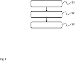
- Fig. 1 shows a flow diagram of a method for calibrating an audio reproduction system 100, 200 with a number of linearly arranged speaker devices 101, 102, 103, 104, 105, 106 for reproducing surround sound signals.
- the method comprises emitting S1 test signals 108, 208, each test signal 108, 208 being emitted via a single one of the speaker devices 101, 102, 103, 104, 105, 106, receiving S2 responses 109, 110, 111, 112, 113, 209, 210, 211, 212, 213 to the test signals 108, 208 via the remaining speaker devices 101, 102, 103, 104, 105, 106 that are not used for emitting the respective test signal 108, 208, and determining S3 calibration parameters 114 for the audio reproduction system 100, 200 based on the received responses 109, 110, 111, 112, 113, 209, 210, 211, 212, 213.
- test signals 108, 208 may e.g. be emitted consecutively or wherein at least two of the test signals 108, 208 are emitted concurrently. Further, the test signals 108, 208 may each comprise a predetermined frequency in the audible signal range or in the ultrasonic signal range.
- the determined calibration parameters 114 may e.g. comprise a room obstacle level value, especially with a value between 0 and 5, especially between 0 and 4 or between 0 and 3 that indicates the level of filling of surroundings of the audio reproduction system 100, 200 with obstacles. This means, that the result of performing the method according to the present invention may be an indication of the filling level of the room with obstacles. This information may then be used by the digital signal processing devices in the audio reproduction system to adapt the audio output accordingly.
- Fig. 2 shows a flow diagram of another method for calibrating an audio reproduction system 100, 200 with a number of linearly arranged speaker devices 101, 102, 103, 104, 105, 106 for reproducing surround sound signals.
- the method of Fig. 2 is based on the method of Fig.
- each test signal 108, 208 being emitted via a single one of the speaker devices 101, 102, 103, 104, 105, 106, and receiving S12 responses 109, 110, 111, 112, 113, 209, 210, 211, 212, 213 to the test signals 108, 208 via the remaining speaker devices 101, 102, 103, 104, 105, 106 that are not used for emitting the respective test signal 108, 208.
- the step of determining S13 calibration parameters 114 for the audio reproduction system 100, 200 based on the received responses 109, 110, 111, 112, 113, 209, 210, 211, 212, 213 comprises four sub-steps S31 - S34.
- Step S31 comprises determining a frequency shift of the received responses 109, 110, 111, 112, 113, 209, 210, 211, 212, 213 in relation to the respective test signal 108, 208.
- the step S32 comprises determining a change of the amplitude, especially the peak amplitude and/or the average amplitude, of the received responses 109, 110, 111, 112, 113, 209, 210, 211, 212, 213 in relation to the respective test signal 108, 208.
- the step S33 comprises determining a distortion level of the received responses 109, 110, 111, 112, 113, 209, 210, 211, 212, 213 in relation to the respective test signal 108, 208.
- steps S31, S32, and S33 are provided to the step of calculating S34 a metric value 217, where the metric value 217 is calculated based on the determined frequency shift and the determined change of the amplitude and the determined distortion level.
- the room obstacle level value may e.g. be determined based on the metric value 217, wherein a threshold value regarding the metric value 217 is provided for every value of the room obstacle level value.
- the maximum metric value 217 may be used as determined for any one of the received responses 109, 110, 111, 112, 113, 209, 210, 211, 212, 213.
- the minimum metric value 217 may be used as determined for any one of the received responses 109, 110, 111, 112, 113, 209, 210, 211, 212, 213, or an average metric value 217 may be used that is calculated as the average of all metric values 217 for all received responses 109, 110, 111, 112, 113, 209, 210, 211, 212, 213.
- Fig. 3 shows a block diagram of an audio reproduction system 100.
- the audio reproduction system 100 comprises six speaker devices 101, 102, 103, 104, 105, 106 that are arranged on a straight line, like e.g. in a soundbar for reproducing surround sound.
- the audio reproduction system 100 further comprises a control unit 107 that is coupled to the speaker devices 101, 102, 103, 104, 105, 106.
- the control unit 107 performs a method as described in conjunction with Figs. 1 and 2 for determining calibration parameters for the speaker devices 101, 102, 103, 104, 105, 106.
- the control unit 107 may emit test signals 108. Each test signal 108 is emitted by the control unit 108 via a single one of the speaker devices 101, 102, 103, 104, 105, 106. The control unit 107 then receives responses 109, 110, 111, 112, 113 to the test signals 108 via the remaining speaker devices 101, 102, 103, 104, 105, 106 that are not used for emitting the respective test signal 108. The control unit 107 determines calibration parameters 114 for the audio reproduction system 100 based on the received responses 109, 110, 111, 112, 113.
- the control unit 107 may emit the test signals 108 consecutively or may emit at least two of the test signals 108 concurrently. In addition, the control unit 107 may provide the test signals 108 each with a predetermined frequency in the audible signal range or in the ultrasonic signal range.
- the control unit 107 may e.g. determine the calibration parameters 114 as a room obstacle level value, especially with a value between 0 and 5, especially between 0 and 4 or between 0 and 3, that indicates the level of filling of surroundings of the audio reproduction system 100 with obstacles.
- control unit 107 may determine a frequency shift of the received responses 109, 110, 111, 112, 113 in relation to the respective test signal 108, and/or determine a change of the amplitude, especially the peak amplitude and/or the average amplitude, of the received responses 109, 110, 111, 112, 113 in relation to the respective test signal 108, and/or determine a distortion level of the received responses 109, 110, 111, 112, 113 in relation to the respective test signal 108.
- the control unit 107 may then calculate a metric value based on the determined frequency shift and/or the determined change of the amplitude and/or the determined distortion level. Finally, the control unit 107 may determine the room obstacle level value based on the metric value, wherein a threshold value regarding the metric value is provided for every value of the room obstacle level value.
- the control unit 107 is especially configured to use the maximum metric value as determined for any one of the received responses 109, 110, 111, 112, 113 as the metric value for determining the room obstacle level value, or to use the minimum metric value as determined for any one of the received responses 109, 110, 111, 112, 113 as the metric value for determining the room obstacle level value, or to use an average metric value that is calculated as the average of all metric values for all received responses 109, 110, 111, 112, 113 as the metric value for determining the room obstacle level value.
- Fig. 4 shows a block diagram of another audio reproduction system 200.
- the audio reproduction system 200 is shown as an abstract block diagram that shows the basic building blocks of a possible embodiment.
- a test signal 208 is provided together with the responses 209 - 213 to a processing unit 215. Based on the test signal 208 and the responses 209 - 213, that are recorded by the speaker devices, the processing unit 215 calculates a metric value 217.
- the metric value 217 may e.g.
- the received responses 109, 110, 111, 112, 113 be calculated based on a frequency shift of the received responses 109, 110, 111, 112, 113 in relation to the respective test signal 108, and/or a change of the amplitude, especially the peak amplitude and/or the average amplitude, of the received responses 109, 110, 111, 112, 113 in relation to the respective test signal 108, and/or a distortion level of the received responses 109, 110, 111, 112, 113 in relation to the respective test signal 108.
- the determined metric value 217 is then provided to comparator 216 that determines a calibration parameter 214, for example a room obstacle level value.
- This calibration parameter 214 may then be used by a digital signal processing stage of the audio reproduction system 200 to adapt the sounds emitted by the single speaker devices
- the present invention provides a method for calibrating an audio reproduction system 100 with a number of linearly arranged speaker devices 101, 102, 103, 104, 105, 106 for reproducing surround sound signals, the method comprising emitting S1 test signals 108, each test signal 108 being emitted via a single one of the speaker devices 101, 102, 103, 104, 105, 106, receiving S2 responses 109, 110, 111, 112, 113 to the test signals 108 via the remaining speaker devices 101, 102, 103, 104, 105, 106 that are not used for emitting the respective test signal 108, and determining S3 calibration parameters 114 for the audio reproduction system 100 based on the received responses 109, 110, 111, 112, 113. Further, the present invention provides a respective audio reproduction system 100.
Landscapes
- Physics & Mathematics (AREA)
- Engineering & Computer Science (AREA)
- Acoustics & Sound (AREA)
- Signal Processing (AREA)
- Circuit For Audible Band Transducer (AREA)
- Stereophonic System (AREA)
Abstract
Description
- The invention relates to a method for calibrating an audio reproduction system. Further, the present invention relates to a respective audio reproduction system.
- Although applicable to any audio reproduction system with multiple speakers, the present invention will mainly be described in conjunction with soundbars.
- In modern multimedia applications, sound may be provided as so called surround sound. Surround sound comprises audio information for speakers that usually are placed around a user. Common speaker setups may e.g. comprise a so called 5.1 setup, where 5 surround speakers are combined with a single subwoofer. Other possible arrangements may e.g. comprise a 7.1 setup, or setups with ceiling speakers, like e.g. a 5.1.2, 5.1.4 or a 7.1.2 setup. It is understood, that other setups are also possible.
- In some situations however, the available space may be limited. This may for example be the case in a living room that is not used as a dedicated home theater. To provide surround sound to users even if the surround speakers may not be placed around the users, so called soundbars have been developed. Soundbars comprise several speakers in a linear arrangement and may e.g. be placed below a TV screen.
- The speakers in a soundbar may e.g. be used as a kind of phased array that allows guiding the maxima of the emitted sound waves to direct sound and simulate surround speakers. Further, soundbars may make use of reflections of the soundwaves at the walls of a room.
- Since the speakers are located very close to each other in a soundbar, the soundbar exhibits a high dependency on the room and objects on the room that accommodates the soundbar. In order to properly generate and emit sound signals with the speakers in a soundbar, the soundbar usually has to be calibrated to provide the correct surround sound experience to the users.
- Accordingly, there is a need for providing a calibration method for soundbars.
- The present invention provides a method with the features of claim 1 and an audio reproduction system with the features of claim 9.
- Accordingly, it is provided:
- A method for calibrating an audio reproduction system with a number of linearly arranged speaker devices for reproducing surround sound signals, the method comprising emitting test signals, each test signal being emitted via a single one of the speaker devices, receiving responses to the test signals via the remaining speaker devices that are not used for emitting the respective test signal, and determining calibration parameters for the audio reproduction system based on the received responses.
- Further, it is provided:
- An audio reproduction system for reproducing surround sound signals, the audio reproduction system comprising a number of linearly arranged speaker devices, and a control unit coupled to the speaker devices and configured to emit test signals, each test signal being emitted via a single one of the speaker devices, receive responses to the test signals via the remaining speaker devices that are not used for emitting the respective test signal, and determine calibration parameters for the audio reproduction system based on the received responses.
- The present invention is based on the finding that speaker devices may be used for reproducing and emitting sound waves and may also be used as microphone-like sensors or recording devices. It is understood, that the sensitivity and other characteristics of a speaker when used as microphone may not be as good as those of a real microphone. However, for the present invention the recording characteristics of speaker devices have been found to suffice.
- The present invention makes use of the above finding and provides a method for calibrating an audio reproduction system with a number of linearly arranged speaker devices. Such an audio reproduction system may e.g. be a soundbar that comprises the speaker devices arranged linearly or on a straight line in a housing of the soundbar, the speakers usually facing the users. It is understood, that for applying the present invention, an audio reproduction system may also comprise additional speaker devices that not necessarily need to be directed to the users or be provided in the linear arrangement. Additional speaker devices may e.g. be oriented to the back of the soundbar or upwards.
- The present invention is based on test signals that are in each case emitted via a single one of the speaker devices of the audio reproduction system.
- The remaining speaker devices may then be used to record the response to the emitted test signal. A response in this context is any signal that is detected or measured via one of the speaker devices as direct response to the respective test signal. The test signal may e.g. be reflected from objects and walls in a room in which the audio reproduction system is accommodated and the remaining speakers may then receive the reflected signals.
- If for example the audio reproduction system comprises six speakers, six test signals may be emitted each via one of the speaker devices. Consequently, five responses to the test signals may be recorded for each test signal by the remaining speaker devices that are not used to emit the respective test signal.
- It is then possible to determine calibration parameters for the audio reproduction system to adapt the emitted surround sound signals according to the properties of the room in which the audio reproduction system is positioned.
- The present invention therefore provides a very simple yet effective way of calibrating the audio reproduction system. Since no dedicated measurement equipment, like e.g. external microphones, is required, the present invention allows calibrating the audio reproduction system whenever required.
- Since the number of users that takes seat in front of the audio reproduction system may already influence the reproduction of surround sound, the calibration according to the present invention may e.g. be performed during startup of the audio reproduction system, every time the audio reproduction system is switched on.
- Further embodiments of the present invention are subject of the further subclaims and of the following description, referring to the drawings.
- In an embodiment, the determined calibration parameters may comprise a room obstacle level value, especially with a value between 0 and 5, especially between 0 and 4 or between 0 and 3, that indicates the level of filling of surroundings, e.g. a room, of the audio reproduction system with obstacles for the sound waves emitted by the audio reproduction system.
- Digital signal processing algorithms in the audio reproduction system that convert the received surround sound signal, e.g. a Dolby Digital 5.1 signal, into driving signals for the single speaker devices, usually require an information about the amount of obstacles in the room in which the audio reproduction system is used.
- This information may be provided as a discrete value that indicates a rough estimate of the filling of the room with obstacles.
- For example a room obstacle level value of 0 may refer to a room with a small number of obstacles or no obstacles. The higher the room obstacle level value the more obstacles are assumed to be in the room. The maximum room obstacle level value therefore refers to a cluttered room.
- In a possible embodiment, a room obstacle level value of 0 refers to an empty or an almost empty room, a room obstacle level value of 1 refers to a medium number of obstacles, and a room obstacle level value of 3 refers to a room with many obstacles or large obstacles.
- By providing the room obstacle level value the present invention may be used with the above mentioned digital signal processing algorithms.
- The digital signal processing algorithms may e.g. output the original sound for the lowest room obstacle level value and may increasingly perform e.g. level or phase shifting and amplitude modifications with increasing room obstacle level value.
- In another embodiment, the test signals are emitted consecutively or at least two of the test signals are emitted concurrently.
- Emitting the test signals consecutively provides for a very simple arrangement, where the responses of the other speaker devices to the respective test signal may be easily recorded. On the other hand, emitting the test signals or at least some of the test signals concurrently shortens the time required for performing the calibration. However, the responses of the speaker devices to the emitted test signals must in each case be separated from the supply signals that are fed to the respective speaker devices with respective signal processing.
- The single test signals may e.g. be chosen with such differences, e.g. in frequency that they or the respective responses may easily be separated e.g. via frequency selective filters for further processing.
- In a further embodiment, the test signals may each comprise a predetermined frequency in the audible signal range or in the ultrasonic signal range.
- Using test signals with frequencies in the audible signal range allows reusing the signal generation means in the audio reproduction system that are optimized for generating audible signals and therefore provides for a very simple calibration. However, the audible signals may be perceived by users as disturbing, especially if the calibration is performed not only at the setup of the audio reproduction system but e.g. at every startup of the audio reproduction system, as hinted at above.
- Therefore, the frequencies of the test signals may also be chosen in the ultrasonic signal range. This allows determining the calibration parameters without users perceiving the test signals. Such a calibration may therefore be performed whenever necessary.
- The calibration with ultrasonic test signals may even be performed during normal operation of the audio reproduction system, i.e. while audio signals are reproduced by the audio reproduction system. This allows adapting the digital signal processing algorithms in the audio reproduction system to changing room situations even during operation of the audio reproduction system.
- In an embodiment, the method may comprise determining a frequency shift of the received responses in relation to the respective test signal, and/or determining a change of the amplitude, especially the peak amplitude and/or the average amplitude, of the received responses in relation to the respective test signal, and/or determining a distortion level of the received responses in relation to the respective test signal.
- It is understood that any adequate type of determination may be performed to determine the frequency shift, the change of amplitude and the distortion level.
- It is for example possible to perform a frequency comparison by converting the received responses into the frequency domain, e.g. by performing a Fourier Transform or a Fast Fourier Transform. In the frequency domain peaks may be identified and the respective frequency spectrum of the received responses and may e.g. be compared with a known frequency or frequencies of the respective test signals. If the frequency of the test signal is not known, the emitted test signal may also be converted into the frequency domain and the peaks in the frequency spectrum may be identified.
- The peaks of the test signals and the respective responses may be at the same frequencies. It is however, possible that the received responses comprise a distorted or blurred frequency spectrum. This may e.g. be detected by determining the average signal in the frequency domain or by comparing the respective center frequencies. It is understood, that a bandpass filter may be applied to the test signals and the received responses as required.
- The change of the amplitude, i.e. the damping of the test signals in the room may e.g. be determined by determining a RMS value or average values of the test signals and the respective received responses.
- Distortions, e.g. the total harmonic distortion, THD, may e.g. be calculated with any moving average technique. For example, the powers of all harmonics and the fundamental frequency of the test signals and the respective responses may be calculated in the frequency domain, e.g. with a moving average filter applied.
- In a further embodiment, the method may comprise calculating a metric value based on the determined frequency shift and/or the determined change of the amplitude and/or the determined distortion level.
- The metric value may for example be provided as a value between 0 and 100 or between 0 and 255. In any case, the determined frequency shift and/or the determined change of the amplitude and/or the determined distortion level may be normalized according to the desired value range of the metric value.
- If the value range of the metric value is chosen to be between 0 and 255, the determined frequency shift and the determined change of the amplitude and the determined distortion level may be normalized to provide values between 0 and 255/3=85. The total sum of the three values for frequency shift and change of the amplitude and distortion level may then be maximally 255.
- Normalizing may e.g. be performed by calculating and applying a normalization factor that is based on the possible minimum and maximum values of the respective input values.
- The metric value may then e.g. be determined as:

- In an embodiment, the room obstacle level value may be determined based on the metric value, wherein a threshold value regarding the metric value may be provided for every value of the room obstacle level value.
- Possible threshold values for a value range of the metric value between 0 and 255 may for example be 20 for the first room obstacle level, 150 for the second room obstacle level and 255 for the third room obstacle level. In this case, the values each represent the upper threshold for the respective room obstacle level.
- Consequently, in the above example a metric value lower than 20 represents the first room obstacle level, a metric value between 20 and lower than 150 represents the second room obstacle value, and a metric value equal to and above 150 represents the third obstacle level.
- It is understood, that the exact threshold values may e.g. be empirically or experimentally determined.
- In another embodiment, as the metric value for determining the room obstacle level value the maximum metric value may be used as determined for any one of the received responses. As alternative, as the metric value for determining the room obstacle level value the minimum metric value may be used as determined for any one of the received responses, or an average metric value may be used that is calculated as the average of all metric values for all received responses.
- If one of the speaker devices of the audio reproduction system is used as sound emitter for the test signals and the other speaker devices are used as microphones, the received signals and the respective metric values may be recorded in a matrix that comprises a number of rows and columns that is one less than the number of speaker devices. For a six-speaker soundbar, after all six speakers emitted a test signal, the resulting matrix would therefore be a 5x5 matrix with respective metric values. A matrix allows easily processing the metric values for determining the room obstacle level value.
- As explained above, different schemes may be used to determine the room obstacle level. For example, the maximum or the minimum value in the matrix may be used to determine the room obstacle level. As further alternative, the mean value may be used.
- It is understood, that the method may also comprise showing the result, i.e. the determined room obstacle level value to a user. The user may then e.g. confirm the determined room obstacle level value or manually modify the determined room obstacle level value.
- For a more complete understanding of the present invention and advantages thereof, reference is now made to the following description taken in conjunction with the accompanying drawings. The invention is explained in more detail below using exemplary embodiments, which are specified in the schematic figures of the drawings, in which:
-
Fig. 1 shows a flow diagram of an embodiment of a method according to the present invention; -
Fig. 2 shows a flow diagram of another embodiment of a method according to the present invention; -
Fig. 3 shows a block diagram of an embodiment of an audio reproduction system according to the present invention; and -
Fig. 4 shows a block diagram of another embodiment of an audio reproduction system according to the present invention. - In the figures like reference signs denote like elements unless stated otherwise.
- For sake of clarity in the following description of the method based
Figs. 1 and2 the reference signs used above in the description of apparatus basedFigs. 3 and4 will be maintained. -
Fig. 1 shows a flow diagram of a method for calibrating anaudio reproduction system 100, 200 with a number of linearly arrangedspeaker devices - The method comprises emitting S1 test signals 108, 208, each
test signal speaker devices S2 responses speaker devices respective test signal S3 calibration parameters 114 for theaudio reproduction system 100, 200 based on the receivedresponses - The test signals 108, 208 may e.g. be emitted consecutively or wherein at least two of the test signals 108, 208 are emitted concurrently. Further, the test signals 108, 208 may each comprise a predetermined frequency in the audible signal range or in the ultrasonic signal range.
- The
determined calibration parameters 114 may e.g. comprise a room obstacle level value, especially with a value between 0 and 5, especially between 0 and 4 or between 0 and 3 that indicates the level of filling of surroundings of theaudio reproduction system 100, 200 with obstacles. This means, that the result of performing the method according to the present invention may be an indication of the filling level of the room with obstacles. This information may then be used by the digital signal processing devices in the audio reproduction system to adapt the audio output accordingly. -
Fig. 2 shows a flow diagram of another method for calibrating anaudio reproduction system 100, 200 with a number of linearly arrangedspeaker devices Fig. 2 is based on the method ofFig. 1 and therefore also comprises a step of emitting S11 test signals 108, 208, eachtest signal speaker devices S12 responses speaker devices respective test signal - The step of determining
S13 calibration parameters 114 for theaudio reproduction system 100, 200 based on the receivedresponses - Step S31 comprises determining a frequency shift of the received
responses respective test signal responses respective test signal responses respective test signal - The results of steps S31, S32, and S33 are provided to the step of calculating S34 a metric value 217, where the metric value 217 is calculated based on the determined frequency shift and the determined change of the amplitude and the determined distortion level.
- The room obstacle level value may e.g. be determined based on the metric value 217, wherein a threshold value regarding the metric value 217 is provided for every value of the room obstacle level value.
- As the metric value 217 for determining the room obstacle level value the maximum metric value 217 may be used as determined for any one of the received
responses responses responses -
Fig. 3 shows a block diagram of anaudio reproduction system 100. Theaudio reproduction system 100 comprises sixspeaker devices - The
audio reproduction system 100 further comprises acontrol unit 107 that is coupled to thespeaker devices control unit 107 performs a method as described in conjunction withFigs. 1 and2 for determining calibration parameters for thespeaker devices - The
control unit 107 may emit test signals 108. Eachtest signal 108 is emitted by thecontrol unit 108 via a single one of thespeaker devices control unit 107 then receivesresponses speaker devices respective test signal 108. Thecontrol unit 107 determinescalibration parameters 114 for theaudio reproduction system 100 based on the receivedresponses - The
control unit 107 may emit the test signals 108 consecutively or may emit at least two of the test signals 108 concurrently. In addition, thecontrol unit 107 may provide the test signals 108 each with a predetermined frequency in the audible signal range or in the ultrasonic signal range. - The
control unit 107 may e.g. determine thecalibration parameters 114 as a room obstacle level value, especially with a value between 0 and 5, especially between 0 and 4 or between 0 and 3, that indicates the level of filling of surroundings of theaudio reproduction system 100 with obstacles. - To determine the
calibration parameters 114 thecontrol unit 107 may determine a frequency shift of the receivedresponses respective test signal 108, and/or determine a change of the amplitude, especially the peak amplitude and/or the average amplitude, of the receivedresponses respective test signal 108, and/or determine a distortion level of the receivedresponses respective test signal 108. - The
control unit 107 may then calculate a metric value based on the determined frequency shift and/or the determined change of the amplitude and/or the determined distortion level. Finally, thecontrol unit 107 may determine the room obstacle level value based on the metric value, wherein a threshold value regarding the metric value is provided for every value of the room obstacle level value. Thecontrol unit 107 is especially configured to use the maximum metric value as determined for any one of the receivedresponses responses responses -
Fig. 4 shows a block diagram of another audio reproduction system 200. The audio reproduction system 200 is shown as an abstract block diagram that shows the basic building blocks of a possible embodiment. - A
test signal 208 is provided together with the responses 209 - 213 to aprocessing unit 215. Based on thetest signal 208 and the responses 209 - 213, that are recorded by the speaker devices, theprocessing unit 215 calculates a metric value 217. The metric value 217 may e.g. be calculated based on a frequency shift of the receivedresponses respective test signal 108, and/or a change of the amplitude, especially the peak amplitude and/or the average amplitude, of the receivedresponses respective test signal 108, and/or a distortion level of the receivedresponses respective test signal 108. - The determined metric value 217 is then provided to
comparator 216 that determines acalibration parameter 214, for example a room obstacle level value. Thiscalibration parameter 214 may then be used by a digital signal processing stage of the audio reproduction system 200 to adapt the sounds emitted by the single speaker devices - Although specific embodiments have been illustrated and described herein, it will be appreciated by those of ordinary skill in the art that a variety of alternate and/or equivalent implementations exist. It should be appreciated that the exemplary embodiment or exemplary embodiments are only examples, and are not intended to limit the scope, applicability, or configuration in any way. Rather, the foregoing summary and detailed description will provide those skilled in the art with a convenient road map for implementing at least one exemplary embodiment, it being understood that various changes may be made in the function and arrangement of elements described in an exemplary embodiment without departing from the scope as set forth in the appended claims and their legal equivalents. Generally, this application is intended to cover any adaptations or variations of the specific embodiments discussed herein.
- Thus, the present invention provides a method for calibrating an
audio reproduction system 100 with a number of linearly arrangedspeaker devices test signal 108 being emitted via a single one of thespeaker devices S2 responses speaker devices respective test signal 108, and determiningS3 calibration parameters 114 for theaudio reproduction system 100 based on the receivedresponses audio reproduction system 100. -
- 100
- audio reproduction system
- 101, 102, 103, 104, 105, 106
- speaker device
- 107, 207
- control unit
- 108,208
- test signal
- 109,110,111,112,113
- response
- 209, 210, 211, 212, 213
- response
- 114, 214
- calibration parameter
- 215
- processing unit
- 216
- comparator
- 217
- metric value
- S1, S2, S3, S11, S12, S13
- method step
- S31, S32, S33, S34
- method step
Claims (15)
- Method for calibrating an audio reproduction system (100, 200) with a number of linearly arranged speaker devices (101, 102, 103, 104, 105, 106) for reproducing surround sound signals, the method comprising:emitting (S1, S11) test signals (108, 208), each test signal (108, 208) being emitted via a single one of the speaker devices (101, 102, 103, 104, 105, 106),receiving (S2, S12) responses (109, 110, 111, 112, 113, 209, 210, 211, 212, 213) to the test signals (108, 208) via the remaining speaker devices (101, 102, 103, 104, 105, 106) that are not used for emitting the respective test signal (108, 208), anddetermining (S3, S13) calibration parameters (114, 214) for the audio reproduction system (100, 200) based on the received responses (109, 110, 111, 112, 113, 209, 210, 211, 212, 213).
- Method according to claim 1, wherein the determined calibration parameters (114, 214) comprise a room obstacle level value, especially with a value between 0 and 5, especially between 0 and 4 or between 0 and 3, that indicates the level of filling of surroundings of the audio reproduction system (100, 200) with obstacles.
- Method according to any one of the preceding claims, wherein the test signals (108, 208) are emitted consecutively or wherein at least two of the test signals (108, 208) are emitted concurrently.
- Method according to any one of the preceding claims, wherein the test signals (108, 208) each comprise a predetermined frequency in the audible signal range or in the ultrasonic signal range.
- Method according to any one of the preceding claims, comprising determining (S31) a frequency shift of the received responses (109, 110, 111, 112, 113, 209, 210, 211, 212, 213) in relation to the respective test signal (108, 208), and/or
comprising determining (S32) a change of the amplitude, especially the peak amplitude and/or the average amplitude, of the received responses (109, 110, 111, 112, 113, 209, 210, 211, 212, 213) in relation to the respective test signal (108, 208), and/or
comprising determining (S33) a distortion level of the received responses (109, 110, 111, 112, 113, 209, 210, 211, 212, 213) in relation to the respective test signal (108, 208). - Method according to claim 5, comprising calculating (S34) a metric value (217) based on the determined frequency shift and/or the determined change of the amplitude and/or the determined distortion level.
- Method according to claims 2 and 6, wherein the room obstacle level value is determined based on the metric value (217), wherein a threshold value regarding the metric value (217) is provided for every value of the room obstacle level value.
- Method according to any one of the preceding claims 6 and 7, wherein as the metric value (217) for determining the room obstacle level value the maximum metric value (217) is used as determined for any one of the received responses (109, 110, 111, 112, 113, 209, 210, 211, 212, 213); or
wherein as the metric value (217) for determining the room obstacle level value the minimum metric value (217) is used as determined for any one of the received responses (109, 110, 111, 112, 113, 209, 210, 211, 212, 213); or
wherein as the metric value (217) for determining the room obstacle level value an average metric value (217) is used that is calculated as the average of all metric values (217) for all received responses (109, 110, 111, 112, 113, 209, 210, 211, 212, 213). - Audio reproduction system (100, 200) for reproducing surround sound signals, the audio reproduction system (100, 200) comprising:a number of linearly arranged speaker devices (101, 102, 103, 104, 105, 106), anda control unit (107) coupled to the speaker devices (101, 102, 103, 104, 105, 106) and configured to emit test signals (108, 208), each test signal (108, 208) being emitted via a single one of the speaker devices (101, 102, 103, 104, 105, 106), receive responses (109, 110, 111, 112, 113, 209, 210, 211, 212, 213) to the test signals (108, 208) via the remaining speaker devices (101, 102, 103, 104, 105, 106) that are not used for emitting the respective test signal (108, 208), and determine calibration parameters (114, 214) for the audio reproduction system (100, 200) based on the received responses (109, 110, 111, 112, 113, 209, 210, 211, 212, 213).
- Audio reproduction system (100, 200) according to claim 9, wherein the control unit (107) is configured to determine the calibration parameters (114, 214) as a room obstacle level value, especially with a value between 0 and 5, especially between 0 and 4 or between 0 and 3, that indicates the level of filling of surroundings of the audio reproduction system (100, 200) with obstacles.
- Audio reproduction system (100, 200) according to any one of the preceding claims 9 to 10, wherein the control unit (107) is configured to emit the test signals (108, 208) consecutively or to emit at least two of the test signals (108, 208) concurrently.
- Audio reproduction system (100, 200) according to any one of the preceding claims 9 to 11, wherein the control unit (107) is configured to provide the test signals (108, 208) each with a predetermined frequency in the audible signal range or in the ultrasonic signal range.
- Audio reproduction system (100, 200) according to any one of the preceding claims 9 to 12, wherein the control unit (107) is configured to determine a frequency shift of the received responses (109, 110, 111, 112, 113, 209, 210, 211, 212, 213) in relation to the respective test signal (108, 208), and/or
to determine a change of the amplitude, especially the peak amplitude and/or the average amplitude, of the received responses (109, 110, 111, 112, 113, 209, 210, 211, 212, 213) in relation to the respective test signal (108, 208), and/or
to determine a distortion level of the received responses (109, 110, 111, 112, 113, 209, 210, 211, 212, 213) in relation to the respective test signal (108, 208). - Audio reproduction system (100, 200) according to claim 13, wherein the control unit (107) is configured to calculate a metric value (217) based on the determined frequency shift and/or the determined change of the amplitude and/or the determined distortion level.
- Audio reproduction system (100, 200) according to claims 10 and 14, wherein the control unit (107) is configured to determine the room obstacle level value based on the metric value (217), wherein a threshold value regarding the metric value (217) is provided for every value of the room obstacle level value, wherein the control unit (107) is especially configured to use the maximum metric value (217) as determined for any one of the received responses (109, 110, 111, 112, 113, 209, 210, 211, 212, 213) as the metric value (217) for determining the room obstacle level value, or to use the minimum metric value (217) as determined for any one of the received responses (109, 110, 111, 112, 113, 209, 210, 211, 212, 213) as the metric value (217) for determining the room obstacle level value, or to use an average metric value (217) that is calculated as the average of all metric values (217) for all received responses (109, 110, 111, 112, 113, 209, 210, 211, 212, 213) as the metric value (217) for determining the room obstacle level value.
Priority Applications (2)
| Application Number | Priority Date | Filing Date | Title |
|---|---|---|---|
| EP17210763.3A EP3506660B1 (en) | 2017-12-27 | 2017-12-27 | Method for calibrating an audio reproduction system and corresponding audio reproduction system |
| TR2017/22915A TR201722915A2 (en) | 2017-12-27 | 2017-12-29 | Method and audio reproduction system. |
Applications Claiming Priority (1)
| Application Number | Priority Date | Filing Date | Title |
|---|---|---|---|
| EP17210763.3A EP3506660B1 (en) | 2017-12-27 | 2017-12-27 | Method for calibrating an audio reproduction system and corresponding audio reproduction system |
Publications (2)
| Publication Number | Publication Date |
|---|---|
| EP3506660A1 true EP3506660A1 (en) | 2019-07-03 |
| EP3506660B1 EP3506660B1 (en) | 2021-01-27 |
Family
ID=60915365
Family Applications (1)
| Application Number | Title | Priority Date | Filing Date |
|---|---|---|---|
| EP17210763.3A Active EP3506660B1 (en) | 2017-12-27 | 2017-12-27 | Method for calibrating an audio reproduction system and corresponding audio reproduction system |
Country Status (2)
| Country | Link |
|---|---|
| EP (1) | EP3506660B1 (en) |
| TR (1) | TR201722915A2 (en) |
Citations (4)
| Publication number | Priority date | Publication date | Assignee | Title |
|---|---|---|---|---|
| EP1651007A2 (en) * | 2004-10-20 | 2006-04-26 | Matsushita Electric Industrial Co., Ltd. | Multichannel sound reproduction apparatus and multichannel sound adjustment method |
| US20090003613A1 (en) * | 2005-12-16 | 2009-01-01 | Tc Electronic A/S | Method of Performing Measurements By Means of an Audio System Comprising Passive Loudspeakers |
| US20120114152A1 (en) * | 2010-11-09 | 2012-05-10 | Andy Nguyen | Determining Loudspeaker Layout Using Audible Markers |
| US20150016642A1 (en) * | 2013-07-15 | 2015-01-15 | Dts, Inc. | Spatial calibration of surround sound systems including listener position estimation |
-
2017
- 2017-12-27 EP EP17210763.3A patent/EP3506660B1/en active Active
- 2017-12-29 TR TR2017/22915A patent/TR201722915A2/en unknown
Patent Citations (4)
| Publication number | Priority date | Publication date | Assignee | Title |
|---|---|---|---|---|
| EP1651007A2 (en) * | 2004-10-20 | 2006-04-26 | Matsushita Electric Industrial Co., Ltd. | Multichannel sound reproduction apparatus and multichannel sound adjustment method |
| US20090003613A1 (en) * | 2005-12-16 | 2009-01-01 | Tc Electronic A/S | Method of Performing Measurements By Means of an Audio System Comprising Passive Loudspeakers |
| US20120114152A1 (en) * | 2010-11-09 | 2012-05-10 | Andy Nguyen | Determining Loudspeaker Layout Using Audible Markers |
| US20150016642A1 (en) * | 2013-07-15 | 2015-01-15 | Dts, Inc. | Spatial calibration of surround sound systems including listener position estimation |
Also Published As
| Publication number | Publication date |
|---|---|
| EP3506660B1 (en) | 2021-01-27 |
| TR201722915A2 (en) | 2019-07-22 |
Similar Documents
| Publication | Publication Date | Title |
|---|---|---|
| US12081183B2 (en) | Customized automated audio tuning | |
| US8059833B2 (en) | Method of compensating audio frequency response characteristics in real-time and a sound system using the same | |
| US9565497B2 (en) | Enhancing audio using a mobile device | |
| US20230146772A1 (en) | Automated audio tuning and compensation procedure | |
| US9380400B2 (en) | Optimizing audio systems | |
| US20170373656A1 (en) | Loudspeaker-room equalization with perceptual correction of spectral dips | |
| US20100104114A1 (en) | Timbral correction of audio reproduction systems based on measured decay time or reverberation time | |
| JPH0787633B2 (en) | Electro-acoustic converter | |
| US8831235B2 (en) | Speaker polarity determination device | |
| DK2839678T3 (en) | Audio system optimization | |
| US12267655B2 (en) | Automated audio tuning launch procedure and report | |
| US10932079B2 (en) | Acoustical listening area mapping and frequency correction | |
| WO2023081534A1 (en) | Automated audio tuning launch procedure and report | |
| JP2006005902A (en) | Amplifier and amplitude frequency characteristics adjusting method | |
| CN112073879A (en) | Audio synchronous playing method and device, video playing equipment and readable storage medium | |
| JP2007043295A (en) | Amplifying apparatus and amplitude frequency characteristic adjusting method | |
| KR100608005B1 (en) | Phase correction method of subwoofer channel signal and device thereof | |
| EP3506660B1 (en) | Method for calibrating an audio reproduction system and corresponding audio reproduction system | |
| JP2017200025A (en) | Acoustic signal compensation apparatus and program thereof | |
| KR100717051B1 (en) | Method and device for correcting tone change according to speaker position | |
| CN120512643A (en) | Method for controlling sound partition in space, electronic device, vehicle and medium | |
| CN121218063A (en) | A method for performing room correction on an audio system, a computer program product, a mobile device, and an audio system. | |
| Bharitkar et al. | Optimization of the bass management filter parameters for multichannel audio applications | |
| Bellmann et al. | Fast Loudspeaker Measurement in Non-Anechoic Environment | |
| CN121013037A (en) | Automatic detection of speaker type |
Legal Events
| Date | Code | Title | Description |
|---|---|---|---|
| PUAI | Public reference made under article 153(3) epc to a published international application that has entered the european phase |
Free format text: ORIGINAL CODE: 0009012 |
|
| STAA | Information on the status of an ep patent application or granted ep patent |
Free format text: STATUS: THE APPLICATION HAS BEEN PUBLISHED |
|
| AK | Designated contracting states |
Kind code of ref document: A1 Designated state(s): AL AT BE BG CH CY CZ DE DK EE ES FI FR GB GR HR HU IE IS IT LI LT LU LV MC MK MT NL NO PL PT RO RS SE SI SK SM TR |
|
| AX | Request for extension of the european patent |
Extension state: BA ME |
|
| STAA | Information on the status of an ep patent application or granted ep patent |
Free format text: STATUS: REQUEST FOR EXAMINATION WAS MADE |
|
| 17P | Request for examination filed |
Effective date: 20191210 |
|
| RBV | Designated contracting states (corrected) |
Designated state(s): AL AT BE BG CH CY CZ DE DK EE ES FI FR GB GR HR HU IE IS IT LI LT LU LV MC MK MT NL NO PL PT RO RS SE SI SK SM TR |
|
| GRAP | Despatch of communication of intention to grant a patent |
Free format text: ORIGINAL CODE: EPIDOSNIGR1 |
|
| STAA | Information on the status of an ep patent application or granted ep patent |
Free format text: STATUS: GRANT OF PATENT IS INTENDED |
|
| INTG | Intention to grant announced |
Effective date: 20200806 |
|
| GRAS | Grant fee paid |
Free format text: ORIGINAL CODE: EPIDOSNIGR3 |
|
| GRAA | (expected) grant |
Free format text: ORIGINAL CODE: 0009210 |
|
| STAA | Information on the status of an ep patent application or granted ep patent |
Free format text: STATUS: THE PATENT HAS BEEN GRANTED |
|
| AK | Designated contracting states |
Kind code of ref document: B1 Designated state(s): AL AT BE BG CH CY CZ DE DK EE ES FI FR GB GR HR HU IE IS IT LI LT LU LV MC MK MT NL NO PL PT RO RS SE SI SK SM TR |
|
| REG | Reference to a national code |
Ref country code: GB Ref legal event code: FG4D |
|
| REG | Reference to a national code |
Ref country code: CH Ref legal event code: EP |
|
| REG | Reference to a national code |
Ref country code: AT Ref legal event code: REF Ref document number: 1359403 Country of ref document: AT Kind code of ref document: T Effective date: 20210215 |
|
| REG | Reference to a national code |
Ref country code: IE Ref legal event code: FG4D |
|
| REG | Reference to a national code |
Ref country code: DE Ref legal event code: R096 Ref document number: 602017032019 Country of ref document: DE |
|
| REG | Reference to a national code |
Ref country code: NL Ref legal event code: MP Effective date: 20210127 |
|
| REG | Reference to a national code |
Ref country code: LT Ref legal event code: MG9D |
|
| REG | Reference to a national code |
Ref country code: AT Ref legal event code: MK05 Ref document number: 1359403 Country of ref document: AT Kind code of ref document: T Effective date: 20210127 |
|
| PG25 | Lapsed in a contracting state [announced via postgrant information from national office to epo] |
Ref country code: HR Free format text: LAPSE BECAUSE OF FAILURE TO SUBMIT A TRANSLATION OF THE DESCRIPTION OR TO PAY THE FEE WITHIN THE PRESCRIBED TIME-LIMIT Effective date: 20210127 Ref country code: GR Free format text: LAPSE BECAUSE OF FAILURE TO SUBMIT A TRANSLATION OF THE DESCRIPTION OR TO PAY THE FEE WITHIN THE PRESCRIBED TIME-LIMIT Effective date: 20210428 Ref country code: FI Free format text: LAPSE BECAUSE OF FAILURE TO SUBMIT A TRANSLATION OF THE DESCRIPTION OR TO PAY THE FEE WITHIN THE PRESCRIBED TIME-LIMIT Effective date: 20210127 Ref country code: NO Free format text: LAPSE BECAUSE OF FAILURE TO SUBMIT A TRANSLATION OF THE DESCRIPTION OR TO PAY THE FEE WITHIN THE PRESCRIBED TIME-LIMIT Effective date: 20210427 Ref country code: PT Free format text: LAPSE BECAUSE OF FAILURE TO SUBMIT A TRANSLATION OF THE DESCRIPTION OR TO PAY THE FEE WITHIN THE PRESCRIBED TIME-LIMIT Effective date: 20210527 Ref country code: BG Free format text: LAPSE BECAUSE OF FAILURE TO SUBMIT A TRANSLATION OF THE DESCRIPTION OR TO PAY THE FEE WITHIN THE PRESCRIBED TIME-LIMIT Effective date: 20210427 Ref country code: LT Free format text: LAPSE BECAUSE OF FAILURE TO SUBMIT A TRANSLATION OF THE DESCRIPTION OR TO PAY THE FEE WITHIN THE PRESCRIBED TIME-LIMIT Effective date: 20210127 |
|
| PG25 | Lapsed in a contracting state [announced via postgrant information from national office to epo] |
Ref country code: AT Free format text: LAPSE BECAUSE OF FAILURE TO SUBMIT A TRANSLATION OF THE DESCRIPTION OR TO PAY THE FEE WITHIN THE PRESCRIBED TIME-LIMIT Effective date: 20210127 Ref country code: RS Free format text: LAPSE BECAUSE OF FAILURE TO SUBMIT A TRANSLATION OF THE DESCRIPTION OR TO PAY THE FEE WITHIN THE PRESCRIBED TIME-LIMIT Effective date: 20210127 Ref country code: LV Free format text: LAPSE BECAUSE OF FAILURE TO SUBMIT A TRANSLATION OF THE DESCRIPTION OR TO PAY THE FEE WITHIN THE PRESCRIBED TIME-LIMIT Effective date: 20210127 Ref country code: PL Free format text: LAPSE BECAUSE OF FAILURE TO SUBMIT A TRANSLATION OF THE DESCRIPTION OR TO PAY THE FEE WITHIN THE PRESCRIBED TIME-LIMIT Effective date: 20210127 Ref country code: SE Free format text: LAPSE BECAUSE OF FAILURE TO SUBMIT A TRANSLATION OF THE DESCRIPTION OR TO PAY THE FEE WITHIN THE PRESCRIBED TIME-LIMIT Effective date: 20210127 |
|
| PG25 | Lapsed in a contracting state [announced via postgrant information from national office to epo] |
Ref country code: IS Free format text: LAPSE BECAUSE OF FAILURE TO SUBMIT A TRANSLATION OF THE DESCRIPTION OR TO PAY THE FEE WITHIN THE PRESCRIBED TIME-LIMIT Effective date: 20210527 |
|
| REG | Reference to a national code |
Ref country code: DE Ref legal event code: R097 Ref document number: 602017032019 Country of ref document: DE |
|
| PG25 | Lapsed in a contracting state [announced via postgrant information from national office to epo] |
Ref country code: CZ Free format text: LAPSE BECAUSE OF FAILURE TO SUBMIT A TRANSLATION OF THE DESCRIPTION OR TO PAY THE FEE WITHIN THE PRESCRIBED TIME-LIMIT Effective date: 20210127 Ref country code: EE Free format text: LAPSE BECAUSE OF FAILURE TO SUBMIT A TRANSLATION OF THE DESCRIPTION OR TO PAY THE FEE WITHIN THE PRESCRIBED TIME-LIMIT Effective date: 20210127 Ref country code: SM Free format text: LAPSE BECAUSE OF FAILURE TO SUBMIT A TRANSLATION OF THE DESCRIPTION OR TO PAY THE FEE WITHIN THE PRESCRIBED TIME-LIMIT Effective date: 20210127 |
|
| PG25 | Lapsed in a contracting state [announced via postgrant information from national office to epo] |
Ref country code: DK Free format text: LAPSE BECAUSE OF FAILURE TO SUBMIT A TRANSLATION OF THE DESCRIPTION OR TO PAY THE FEE WITHIN THE PRESCRIBED TIME-LIMIT Effective date: 20210127 Ref country code: SK Free format text: LAPSE BECAUSE OF FAILURE TO SUBMIT A TRANSLATION OF THE DESCRIPTION OR TO PAY THE FEE WITHIN THE PRESCRIBED TIME-LIMIT Effective date: 20210127 Ref country code: RO Free format text: LAPSE BECAUSE OF FAILURE TO SUBMIT A TRANSLATION OF THE DESCRIPTION OR TO PAY THE FEE WITHIN THE PRESCRIBED TIME-LIMIT Effective date: 20210127 |
|
| PLBE | No opposition filed within time limit |
Free format text: ORIGINAL CODE: 0009261 |
|
| STAA | Information on the status of an ep patent application or granted ep patent |
Free format text: STATUS: NO OPPOSITION FILED WITHIN TIME LIMIT |
|
| 26N | No opposition filed |
Effective date: 20211028 |
|
| PG25 | Lapsed in a contracting state [announced via postgrant information from national office to epo] |
Ref country code: ES Free format text: LAPSE BECAUSE OF FAILURE TO SUBMIT A TRANSLATION OF THE DESCRIPTION OR TO PAY THE FEE WITHIN THE PRESCRIBED TIME-LIMIT Effective date: 20210127 Ref country code: AL Free format text: LAPSE BECAUSE OF FAILURE TO SUBMIT A TRANSLATION OF THE DESCRIPTION OR TO PAY THE FEE WITHIN THE PRESCRIBED TIME-LIMIT Effective date: 20210127 |
|
| PG25 | Lapsed in a contracting state [announced via postgrant information from national office to epo] |
Ref country code: SI Free format text: LAPSE BECAUSE OF FAILURE TO SUBMIT A TRANSLATION OF THE DESCRIPTION OR TO PAY THE FEE WITHIN THE PRESCRIBED TIME-LIMIT Effective date: 20210127 |
|
| PG25 | Lapsed in a contracting state [announced via postgrant information from national office to epo] |
Ref country code: IT Free format text: LAPSE BECAUSE OF FAILURE TO SUBMIT A TRANSLATION OF THE DESCRIPTION OR TO PAY THE FEE WITHIN THE PRESCRIBED TIME-LIMIT Effective date: 20210127 |
|
| PG25 | Lapsed in a contracting state [announced via postgrant information from national office to epo] |
Ref country code: IS Free format text: LAPSE BECAUSE OF FAILURE TO SUBMIT A TRANSLATION OF THE DESCRIPTION OR TO PAY THE FEE WITHIN THE PRESCRIBED TIME-LIMIT Effective date: 20210527 |
|
| PG25 | Lapsed in a contracting state [announced via postgrant information from national office to epo] |
Ref country code: MC Free format text: LAPSE BECAUSE OF FAILURE TO SUBMIT A TRANSLATION OF THE DESCRIPTION OR TO PAY THE FEE WITHIN THE PRESCRIBED TIME-LIMIT Effective date: 20210127 |
|
| REG | Reference to a national code |
Ref country code: CH Ref legal event code: PL |
|
| REG | Reference to a national code |
Ref country code: BE Ref legal event code: MM Effective date: 20211231 |
|
| PG25 | Lapsed in a contracting state [announced via postgrant information from national office to epo] |
Ref country code: LU Free format text: LAPSE BECAUSE OF NON-PAYMENT OF DUE FEES Effective date: 20211227 Ref country code: IE Free format text: LAPSE BECAUSE OF NON-PAYMENT OF DUE FEES Effective date: 20211227 |
|
| PG25 | Lapsed in a contracting state [announced via postgrant information from national office to epo] |
Ref country code: FR Free format text: LAPSE BECAUSE OF NON-PAYMENT OF DUE FEES Effective date: 20211231 Ref country code: BE Free format text: LAPSE BECAUSE OF NON-PAYMENT OF DUE FEES Effective date: 20211231 |
|
| PG25 | Lapsed in a contracting state [announced via postgrant information from national office to epo] |
Ref country code: LI Free format text: LAPSE BECAUSE OF NON-PAYMENT OF DUE FEES Effective date: 20211231 Ref country code: CH Free format text: LAPSE BECAUSE OF NON-PAYMENT OF DUE FEES Effective date: 20211231 |
|
| PG25 | Lapsed in a contracting state [announced via postgrant information from national office to epo] |
Ref country code: NL Free format text: LAPSE BECAUSE OF NON-PAYMENT OF DUE FEES Effective date: 20210127 Ref country code: CY Free format text: LAPSE BECAUSE OF FAILURE TO SUBMIT A TRANSLATION OF THE DESCRIPTION OR TO PAY THE FEE WITHIN THE PRESCRIBED TIME-LIMIT Effective date: 20210127 |
|
| PG25 | Lapsed in a contracting state [announced via postgrant information from national office to epo] |
Ref country code: HU Free format text: LAPSE BECAUSE OF FAILURE TO SUBMIT A TRANSLATION OF THE DESCRIPTION OR TO PAY THE FEE WITHIN THE PRESCRIBED TIME-LIMIT; INVALID AB INITIO Effective date: 20171227 |
|
| PG25 | Lapsed in a contracting state [announced via postgrant information from national office to epo] |
Ref country code: MK Free format text: LAPSE BECAUSE OF FAILURE TO SUBMIT A TRANSLATION OF THE DESCRIPTION OR TO PAY THE FEE WITHIN THE PRESCRIBED TIME-LIMIT Effective date: 20210127 |
|
| PG25 | Lapsed in a contracting state [announced via postgrant information from national office to epo] |
Ref country code: MT Free format text: LAPSE BECAUSE OF FAILURE TO SUBMIT A TRANSLATION OF THE DESCRIPTION OR TO PAY THE FEE WITHIN THE PRESCRIBED TIME-LIMIT Effective date: 20210127 |
|
| PGFP | Annual fee paid to national office [announced via postgrant information from national office to epo] |
Ref country code: TR Payment date: 20251223 Year of fee payment: 9 |
|
| PGFP | Annual fee paid to national office [announced via postgrant information from national office to epo] |
Ref country code: GB Payment date: 20260128 Year of fee payment: 9 |
|
| PGFP | Annual fee paid to national office [announced via postgrant information from national office to epo] |
Ref country code: DE Payment date: 20260223 Year of fee payment: 9 |