EP3506577A1 - Method and apparatus for calculating blind equalization error and storage medium - Google Patents
Method and apparatus for calculating blind equalization error and storage medium Download PDFInfo
- Publication number
- EP3506577A1 EP3506577A1 EP17842613.6A EP17842613A EP3506577A1 EP 3506577 A1 EP3506577 A1 EP 3506577A1 EP 17842613 A EP17842613 A EP 17842613A EP 3506577 A1 EP3506577 A1 EP 3506577A1
- Authority
- EP
- European Patent Office
- Prior art keywords
- mse
- state
- error vector
- threshold
- maximum value
- Prior art date
- Legal status (The legal status is an assumption and is not a legal conclusion. Google has not performed a legal analysis and makes no representation as to the accuracy of the status listed.)
- Granted
Links
Images




Classifications
-
- H—ELECTRICITY
- H04—ELECTRIC COMMUNICATION TECHNIQUE
- H04L—TRANSMISSION OF DIGITAL INFORMATION, e.g. TELEGRAPHIC COMMUNICATION
- H04L25/00—Baseband systems
- H04L25/02—Details ; arrangements for supplying electrical power along data transmission lines
- H04L25/03—Shaping networks in transmitter or receiver, e.g. adaptive shaping networks
- H04L25/03006—Arrangements for removing intersymbol interference
- H04L25/03012—Arrangements for removing intersymbol interference operating in the time domain
- H04L25/03019—Arrangements for removing intersymbol interference operating in the time domain adaptive, i.e. capable of adjustment during data reception
- H04L25/03038—Arrangements for removing intersymbol interference operating in the time domain adaptive, i.e. capable of adjustment during data reception with a non-recursive structure
-
- H—ELECTRICITY
- H04—ELECTRIC COMMUNICATION TECHNIQUE
- H04L—TRANSMISSION OF DIGITAL INFORMATION, e.g. TELEGRAPHIC COMMUNICATION
- H04L25/00—Baseband systems
- H04L25/02—Details ; arrangements for supplying electrical power along data transmission lines
- H04L25/03—Shaping networks in transmitter or receiver, e.g. adaptive shaping networks
- H04L25/03891—Spatial equalizers
- H04L25/03961—Spatial equalizers design criteria
- H04L25/03968—Spatial equalizers design criteria mean-square error [MSE]
-
- H—ELECTRICITY
- H04—ELECTRIC COMMUNICATION TECHNIQUE
- H04L—TRANSMISSION OF DIGITAL INFORMATION, e.g. TELEGRAPHIC COMMUNICATION
- H04L25/00—Baseband systems
- H04L25/02—Details ; arrangements for supplying electrical power along data transmission lines
- H04L25/03—Shaping networks in transmitter or receiver, e.g. adaptive shaping networks
- H04L25/03006—Arrangements for removing intersymbol interference
- H04L25/03012—Arrangements for removing intersymbol interference operating in the time domain
- H04L25/03019—Arrangements for removing intersymbol interference operating in the time domain adaptive, i.e. capable of adjustment during data reception
- H04L25/03057—Arrangements for removing intersymbol interference operating in the time domain adaptive, i.e. capable of adjustment during data reception with a recursive structure
- H04L25/0307—Arrangements for removing intersymbol interference operating in the time domain adaptive, i.e. capable of adjustment during data reception with a recursive structure using blind adaptation
-
- H—ELECTRICITY
- H04—ELECTRIC COMMUNICATION TECHNIQUE
- H04L—TRANSMISSION OF DIGITAL INFORMATION, e.g. TELEGRAPHIC COMMUNICATION
- H04L25/00—Baseband systems
- H04L25/02—Details ; arrangements for supplying electrical power along data transmission lines
- H04L25/03—Shaping networks in transmitter or receiver, e.g. adaptive shaping networks
- H04L25/03006—Arrangements for removing intersymbol interference
- H04L2025/03592—Adaptation methods
- H04L2025/03598—Algorithms
- H04L2025/03681—Control of adaptation
- H04L2025/037—Detection of convergence state
Definitions
- the present invention relates to communications and, in particular, to a method and apparatus for calculating a blind equalization error and a storage medium.
- FIG.1 is an application scenario of a 100G DSP chip.
- the 100G DSP chip is disposed in a 100G optical module in a 100G line card and is mainly used for digital signal processing.
- a received optical signal needs to be converted into a digital signal.
- a problem of polarization mode dispersion will appear in long-distance transmission of the optical signal.
- the problem is usually solved by means of the blind equalization technology, as an adaptive equalization technology which can equalize the channel only by using prior information of a receiving sequence and without a training sequence.
- the calculation of the error vector in the blind equalization technology mainly refers to calculation of the error vector by using various error calculation methods in parallel and determination of the final error vector according to the calculation results of the error calculation methods.
- embodiments of the present invention provide a method and apparatus for calculating a blind equalization error and a storage medium, to implement purposes of calculating the blind equalization error in a simple way, saving hardware resources and reducing power consumption.
- a method for calculating a blind equalization error includes:
- the method further includes:
- the method further includes:
- the first error vector, the second error vector, the third error vector, the fourth error vector and the fifth error vector each includes an error vector in X-polarized state and an error vector in Y-polarized state
- the first MSE maximum value, the second MSE maximum value, the third MSE maximum value, the fourth MSE maximum value and the fifth MSE maximum value each includes an MSE maximum value in X-polarized state and an MSE maximum value in Y-polarized state
- the first MSE mean value, the second MSE mean value, the third MSE mean value, the fourth MSE mean value and the fifth MSE mean value each includes an MSE mean value in X-polarized state and an MSE mean value in Y-polarized state.
- the determining whether the equalizer enters a multi-mode steady-state converging state according to the second MSE maximum value and the second MSE mean value includes: if a first MSE maximum value in X-polarized state and a first MSE maximum value in Y-polarized state both are less than a threshold 1, that a first MSE mean value in X-polarized state and a first MSE mean value in Y-polarized state both are less than a threshold 2, and that a 4S test is passed, the equalizer enters the single-mode steady-state converging state; otherwise, the equalizer does not enter the single-mode steady-state converging state.
- the determining whether the equalizer exits the single-mode steady-state converging state according to the second MSE maximum value and the second MSE mean value includes: if a second MSE maximum value in X-polarized state and a second MSE maximum value in Y-polarized state both are greater than a threshold 3, that a second MSE mean value in X-polarized state and a second MSE mean value in Y-polarized state both are greater than a threshold 4, and that the 4S test is passed, the equalizer exits the single-mode steady-state converging state; otherwise, the equalizer stays in the single-mode steady-state converging state.
- the determining whether the equalizer enters a multi-mode steady-state converging state according to the second MSE maximum value and the second MSE mean value includes: if the second MSE maximum value in X-polarized state and the second MSE maximum value in Y-polarized state both are less than a threshold 5, that the second MSE mean value in X-polarized state and the second MSE mean value in Y-polarized state both are less than a threshold 6, and that the 4S test is passed, the equalizer enters the multi-mode steady-state converging state; otherwise, the equalizer stays in the single-mode steady-state converging state.
- the determining whether the equalizer exits the multi-mode steady-state converging state according to the fourth MSE maximum value and the fourth MSE mean value includes: if a fourth MSE maximum value in X-polarized state and a fourth MSE maximum value in Y-polarized state both are greater than a threshold 7, that a fourth MSE mean value in X-polarized state and a fourth MSE mean value in Y-polarized state both are greater than a threshold 8, and that the 4S test is passed, the equalizer exits the multi-mode steady-state converging state; otherwise, the equalizer stays in the multi-mode steady-state converging state.
- the threshold 1, the threshold 2, the threshold 3, the threshold 4, the threshold 5, the threshold 6, the threshold 7 and the threshold 8 are obtained through a channel simulation experiment, and the threshold 5 ⁇ the threshold 7 ⁇ the threshold 1 ⁇ the threshold 3, and the threshold 6 ⁇ the threshold 8 ⁇ the threshold 2 ⁇ the threshold 4.
- An apparatus for calculating a blind equalization error includes:
- the calculation module is further configured to calculate a second MSE maximum value and a second MSE mean value according to the second error vector, calculate a third error vector according to the first error vector parameter group if the equalizer exits the single-mode steady-state converging state, and calculate a third MSE maximum value and a third MSE mean value according to the third error vector.
- the determination module is further configured to determine whether the equalizer exits the single-mode steady-state converging state according to the second MSE maximum value and the second MSE mean value, and determine whether the equalizer enters the single-mode steady-state converging state according to the third MSE maximum value and the third MSE mean value.
- the determination module is further configured to determine whether the equalizer enters a multi-mode steady-state converging state according to the second MSE maximum value and the second MSE mean value, determine whether the equalizer exits the multi-mode steady-state converging state according to a fourth MSE maximum value and a fourth MSE mean value, and determine whether the equalizer enters the single-mode steady-state converging state according to a fifth MSE maximum value and a fifth MSE mean value.
- the configuration module is further configured to configure a second error vector parameter group if the equalizer enters the multi-mode steady-state converging state and a preset duration expires; and configure the first error vector parameter group if the equalizer exits the multi-mode steady-state converging state.
- the calculation module is further configured to calculate a fourth error vector according to the second error vector parameter group, calculate the fourth MSE maximum value and the fourth MSE mean value according to the fourth error vector, calculate a fifth error vector according to the first error vector parameter group, and calculate the fifth MSE maximum value and the fifth MSE mean value according to the fifth error vector.
- the first error vector, the second error vector, the third error vector, the fourth error vector and the fifth error vector each includes an error vector in X-polarized state and an error vector in Y-polarized state
- the first MSE maximum value, the second MSE maximum value, the third MSE maximum value, the fourth MSE maximum value and the fifth MSE maximum value each includes an MSE maximum value in X-polarized state and an MSE maximum value in Y-polarized state
- the first MSE mean value, the second MSE mean value, the third MSE mean value, the fourth MSE mean value and the fifth MSE mean value each includes an MSE mean value in X-polarized state and an MSE mean value in Y-polarized state.
- the determination module is configured to: determine whether a first MSE maximum value in X-polarized state and a first MSE maximum value in Y-polarized state both are less than a threshold 1, whether a first MSE mean value in X-polarized state and a first MSE mean value in Y-polarized state both are less than a threshold 2, and whether a 4S test is passed; determine whether a second MSE maximum value in X-polarized state and a second MSE maximum value in Y-polarized state both are greater than a threshold 3, whether a second MSE mean value in X-polarized state and a second MSE mean value in Y-polarized state both are greater than a threshold 4, and whether the 4S test is passed; determine whether the second MSE maximum value in X-polarized state and the second MSE maximum value in Y-polarized state both are less than a threshold 5, whether the second MSE mean value in X-polarized state and the second MSE mean value in Y-polarized state both are
- the threshold 1, the threshold 2, the threshold 3, the threshold 4, the threshold 5, the threshold 6, the threshold 7 and the threshold 8 are obtained through a channel simulation experiment, and the threshold 5 ⁇ the threshold 7 ⁇ the threshold 1 ⁇ the threshold 3, and the threshold 6 ⁇ the threshold 8 ⁇ the threshold 2 ⁇ the threshold 4.
- the embodiments of the present invention provide a method and apparatus for calculating a blind equalization error and a storage medium.
- the method includes: configuring initial error vector parameter groups, calculating a blind equalization error vector, calculating a value of a mean square error (MSE) according to an error vector, determining a converging state of an equalizer according to the value of the MSE, determining whether to configure different error vector parameter groups for different converging states, and calculating a blind equalization error according to the determined error vector parameter groups, thereby implementing a purpose of dynamically calculating the blind equalization error in a simple way, saving hardware resources and reducing power consumption.
- MSE mean square error
- FIG. 2 is a schematic diagram of input and output of a butterfly filter. As shown in FIG. 2 , a signal X and a signal Y are inputted. The signal X and the signal Y interfere with each other. The part of the signal X which is not interfered is H xx , and the part of the signal Y which is not interfered is H yy .
- H xy The interference of the signal Y with the signal X causes H xy , and the influence of the signal X on the signal Y causes H yx .
- H xx and H xy are processed and a signal X' is outputted.
- H yy and H yx are processed and a signal Y' is outputted.
- h xx (n-1) is a coefficient calculated last time
- X in * is an input vector in X-polarized state
- X out is a filtered output vector in X-polarized state
- k is determined by hardware delay
- ⁇ is a configurable step factor
- len is the amount of configurable data
- eps_x is an error vector in X-polarized state.
- FIG. 3 is a flowchart of a method for calculating a blind equalization error according to an embodiment 1 of the present invention. As shown in FIG. 3 , the method provided by the embodiment includes following steps.
- step 101 a first error vector parameter group is configured.
- the error vector parameter group has a format of para(R1, R2, R3, w1, w2, w3).
- the first error vector parameter group is para1(R 0 _v, R 0 _v, R 0 _v, w 0 _v, w 0 _v, w 0 _v).
- the first error vector parameter group is para2(R_v, R_v, R_v, w_v, w_v, w_v, w_v).
- the R 0 _v and the R_v denote modulus values, which are calculated through the constant modulus algorithm.
- the w 0 _v and the w_v denote the weights corresponding to respective modulus values, which are obtained through a channel simulation experiment.
- step 102 a first error vector is calculated according to the first error vector parameter group.
- step 103 a first MSE maximum value and a first MSE mean value are calculated according to the first error vector.
- step 104 whether an equalizer enters a single-mode steady-state converging state is determined according to the first MSE maximum value and the first MSE mean value.
- step 105 if the equalizer enters the single-mode steady-state converging state, a second error vector is calculated according to the first error vector parameter group.
- the method further includes following steps.
- step 106 a second MSE maximum value and a second MSE mean value are calculated according to the second error vector.
- step 107a whether the equalizer exits the single-mode steady-state converging state is determined according to the second MSE maximum value and the second MSE mean value.
- step 108a if the equalizer exits the single-mode steady-state converging state, a third error vector is calculated according to the first error vector parameter group.
- step 109a a third MSE maximum value and a third MSE mean value are calculated according to the third error vector.
- step 110a whether the equalizer enters the single-mode steady-state converging state is determined according to the third MSE maximum value and the third MSE mean value.
- the method provided by this embodiment is a method for calculating a blind equalization error when the equalizer is in the 100G working mode, and a method for calculating a blind equalization error when the equalizer is in the 200G working mode but does not enter the multi-mode steady-state converging state.
- the method for calculating a blind equalization error configures the first error vector parameter group, calculates the error vector, calculates the value of the MSE according to the error vector, determines whether the equalizer enters the single-mode steady-state converging state according to the value of the MSE, and calculates the error vector, thereby implementing a purpose of dynamically calculating the blind equalization error in a simple way, saving hardware resources and reducing power consumption.
- FIG. 4 is a flowchart of a method for calculating a blind equalization error according to an embodiment 2 of the present invention. As shown in FIG. 4 , after the step 106, the method provided by the embodiment further includes following steps.
- step 107b whether the equalizer enters a multi-mode steady-state converging state is determined according to the second MSE maximum value and the second MSE mean value.
- step 108b if the equalizer enters the multi-mode steady-state converging state and a preset duration expires, a second error vector parameter group is configured.
- the format of the second error vector parameter group is para3(R 1 _v, R 2 _v, R 3 _v, w 1 _v, w 2 _v, w 3 _v).
- the R 1 _v, the R 2 _v and the R 3 _v denote modulus values, which are calculated through the constant modulus algorithm.
- the w 1 _v, w 2 _v and w 3 _v denote the weights corresponding to respective modulus values, which are obtained through channel simulation experiment.
- step 109b a fourth error vector is calculated according to the second error vector parameter group.
- step 110b a fourth MSE maximum value and a fourth MSE mean value are calculated according to the fourth error vector.
- step 111b whether the equalizer exits the multi-mode steady-state converging state is determined according to the fourth MSE maximum value and the fourth MSE mean value.
- step 112b if the equalizer exits the multi-mode steady-state converging state, the first error vector parameter group is configured.
- a fifth error vector is calculated according to the first error vector parameter group.
- a fifth MSE maximum value and a fifth MSE mean value are calculated according to the fifth error vector.
- step 115b whether the equalizer enters the single-mode steady-state converging state is determined according to the fifth MSE maximum value and the fifth MSE mean value.
- the equalizer cannot directly enter the multi-mode steady-state converging state and it needs to first determine whether to enter the single-mode steady-state converging state and then determine whether to enter the multi-mode steady-state converging state.
- the method provided by this embodiment is a method for calculating a blind equalization error when the equalizer in the 200G working mode enters the multi-mode steady-state converging state.
- the first error vector, the second error vector, the third error vector, the fourth error vector and the fifth error vector each includes an error vector in X-polarized state and an error vector in Y-polarized state
- the first MSE maximum value, the second MSE maximum value, the third MSE maximum value, the fourth MSE maximum value and the fifth MSE maximum value each includes an MSE maximum value in X-polarized state and an MSE maximum value in Y-polarized state
- the first MSE mean value, the second MSE mean value, the third MSE mean value, the fourth MSE mean value and the fifth MSE mean value each includes an MSE mean value in X-polarized state and an MSE mean value in Y-polarized state.
- the step in which whether an equalizer enters a single-mode steady-state converging state is determined according to the first MSE maximum value and the first MSE mean value specifically includes: if a first MSE maximum value in X-polarized state and a first MSE maximum value in Y-polarized state both are less than a threshold 1, that a first MSE mean value in X-polarized state and a first MSE mean value in Y-polarized state both are less than a threshold 2, and that a 4S test is passed, the equalizer enters the single-mode steady-state converging state; otherwise, the equalizer does not enter the single-mode steady-state converging state.
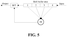
- FIG. 5 is a schematic diagram of a process of a 4S test.
- an SET field is set to be 1, which means that the 4S test is passed.
- the first MSE maximum value in X-polarized state and the first MSE maximum value in Y-polarized state are respectively max_mse_x1 and max_mse_y1
- the first MSE mean value in X-polarized state and the first MSE mean value in Y-polarized state are respectively mean_mse-x1 and mean_mse_y1.
- the step in which whether the equalizer exits the single-mode steady-state converging state is determined according to the second MSE maximum value and the second MSE mean value specifically includes: if a second MSE maximum value in X-polarized state and a second MSE maximum value in Y-polarized state both are greater than a threshold 3, that a second MSE mean value in X-polarized state and a second MSE mean value in Y-polarized state both are greater than a threshold 4, and that the 4S test is passed, the equalizer exits the single-mode steady-state converging state; otherwise, the equalizer stays in the single-mode steady-state converging state.
- the step in which whether the equalizer enters a multi-mode steady-state converging state is determined according to the second MSE maximum value and the second MSE mean value specifically includes: if the second MSE maximum value in X-polarized state and the second MSE maximum value in Y-polarized state both are less than a threshold 5, that the second MSE mean value in X-polarized state and the second MSE mean value in Y-polarized state both are less than a threshold 6, and that the 4S test is passed, the equalizer exits the multi-mode steady-state converging state; otherwise, the equalizer stays in the single-mode steady-state converging state.
- the step in which whether the equalizer exits the multi-mode steady-state converging state is determined according to the fourth MSE maximum value and the fourth MSE mean value specifically includes: if a fourth MSE maximum value in X-polarized state and a fourth MSE maximum value in Y-polarized state both are greater than a threshold 7, that a fourth MSE mean value in X-polarized state and a fourth MSE mean value in Y-polarized state both are greater than a threshold 8, and that the 4S test is passed, the equalizer exits the multi-mode steady-state converging state; otherwise, the equalizer stays in the multi-mode steady-state converging state.
- the threshold 1, the threshold 2, the threshold 3, the threshold 4, the threshold 5, the threshold 6, the threshold 7 and the threshold 8 are obtained through the channel simulation experiment, and the threshold 5 ⁇ the threshold 7 ⁇ the threshold 1 ⁇ the threshold 3, and the threshold 6 ⁇ the threshold 8 ⁇ the threshold 2 ⁇ the threshold 4.
- the method for calculating a blind equalization error configures the first error vector parameter group, calculates a blind equalization error vector, calculates the value of the MSE according to the error vector, determines the converging state of the equalizer according to the value of the MSE, configures the second error vector parameter group when it is determined that the equalizer enters the multi-mode steady-state converging state, and calculates the error according to the new configured second error vector parameter group, thereby implementing a purpose of dynamically calculating the blind equalization error in a simple way, saving hardware resources and reducing power consumption.
- FIG. 6 is a flowchart of a method for calculating a blind equalization error according to an embodiment of the present invention. As shown in FIG. 6 , the method provided by the embodiment includes following steps.
- the equalizer is in a non-converging state.
- the first error vector parameter group para2 is configured, the first error vector eps_x1 in X-polarized state and the first error vector eps_y1 in Y-polarized state are calculated according to the first error vector parameter group para2, and both the first MSE maximum value max_mse_x1 and the first MSE mean value mean_mse_x1 in X-polarized state and both the first MSE maximum value max_mse_y1 and the first MSE mean value mean_mse_y1 in Y-polarized state are calculated respectively according to the eps_x1 and the eps_y1.
- the second error vector eps_x2 in X-polarized state and the second error vector eps_y2 in Y-polarized state are calculated according to the first error vector parameter group para2, and both the second MSE maximum value max_mse_x2 and the second MSE mean value mean_mse_x2 in X-polarized state and both the second MSE maximum value max_mse_y2 and the second MSE mean value mean_mse_y2 in Y-polarized state are calculated respectively according to the eps_x2 and the eps_y2.
- the equalizer enters the multi-mode steady-state converging state.
- the third error vector eps_x3 in X-polarized state and the third error vector eps_y3 in Y-polarized state are calculated according to the first error vector parameter group para2
- both the third MSE maximum value max_mse_x3 and the third MSE mean value mean_mse_x3 in X-polarized state and both the third MSE maximum value max_mse_y3 and the third MSE mean value mean_mse_y3 in Y-polarized state are calculated respectively according to the eps_x3 and the eps_y3, and whether the equalizer enters the single-mode steady-state converging state again is determined.
- the second error vector parameter group para3 is configured, the fourth error vector eps_x4 in X-polarized state and the fourth error vector eps_y4 in Y-polarized state are calculated according to the second error vector parameter group para3, and both the fourth MSE maximum value max_mse_x4 and the fourth MSE mean value mean_mse_x4 in X-polarized state and both the fourth MSE maximum value max_mse_y4 and the fourth MSE mean value mean_mse_y4 in Y-polarized state are calculated respectively according to the eps_x4 and the eps_y4.
- the first error vector parameter group para2 is configured, the fifth error vector eps_x5 in X-polarized state and the fifth error vector eps_y5 in Y-polarized state are calculated according to the first error vector parameter group para2, and both the fifth MSE maximum value max_mse_x5 and the fifth MSE mean value mean_mse_x5 in X-polarized state and both the fifth MSE maximum value max_mse_y5 and the fifth MSE mean value mean_mse_y5 in Y-polarized state are calculated respectively according to the eps_x5 and the eps_y5.
- the method for calculating a blind equalization error configures the first error vector parameter group, calculates a blind equalization error vector, calculates the value of the MSE according to the error vector, determines the converging state of the equalizer according to the value of the MSE, configures the second error vector parameter group when it is determined that the equalizer enters the multi-mode steady-state converging state, and calculates the error according to the new configured second error vector parameter group, thereby implementing a purpose of dynamically calculating the blind equalization error in a simple way, saving hardware resources and reducing power consumption.
- FIG. 7 is a structural diagram of an apparatus for calculating a blind equalization error according to an embodiment of the present invention.
- the apparatus provided by the embodiment includes a configuration module 10, a calculation module 11 and a determination module 12.
- the configuration module 10 is configured to configure a first error vector parameter group.
- the calculation module 11 is configured to calculate a first error vector according to the first error vector parameter group, calculate a first MSE maximum value and a first MSE mean value according to the first error vector, and calculate a second error vector according to the first error vector parameter group if an equalizer enters a single-mode steady-state converging state.
- the determination module 12 is configured to determine whether the equalizer enters the single-mode steady-state converging state according to the first MSE maximum value and the first MSE mean value.
- the calculation module 11 is further configured to calculate a second MSE maximum value and a second MSE mean value according to the second error vector, calculate a third error vector according to the first error vector parameter group if the equalizer exits the single-mode steady-state converging state, and calculate a third MSE maximum value and a third MSE mean value according to the third error vector.
- the determination module 12 is further configured to determine whether the equalizer exits the single-mode steady-state converging state according to the second MSE maximum value and the second MSE mean value, and determine whether the equalizer enters the single-mode steady-state converging state according to the third MSE maximum value and the third MSE mean value.
- the determination module 12 is further configured to determine whether the equalizer enters a multi-mode steady-state converging state according to the second MSE maximum value and the second MSE mean value, determine whether the equalizer exits the multi-mode steady-state converging state according to a fourth MSE maximum value and a fourth MSE mean value, and determine whether the equalizer enters the single-mode steady-state converging state according to a fifth MSE maximum value and a fifth MSE mean value.
- the configuration module 10 is further configured to configure a second error vector parameter group if the equalizer enters the multi-mode steady-state converging state and a preset duration expires; and configure the first error vector parameter group if the equalizer exits the multi-mode steady-state converging state.
- the calculation module 11 is further configured to calculate a fourth error vector according to the second error vector parameter group, calculate the fourth MSE maximum value and the fourth MSE mean value according to the fourth error vector, calculate a fifth error vector according to the first error vector parameter group, and calculate the fifth MSE maximum value and the fifth MSE mean value according to the fifth error vector.
- the determination module is specifically configured to:
- the threshold 1, the threshold 2, the threshold 3, the threshold 4, the threshold 5, the threshold 6, the threshold 7 and the threshold 8 are obtained through a channel simulation experiment, and the threshold 5 ⁇ the threshold 7 ⁇ the threshold 1 ⁇ the threshold 3, and the threshold 6 ⁇ the threshold 8 ⁇ the threshold 2 ⁇ the threshold 4.
- the first error vector, the second error vector, the third error vector, the fourth error vector and the fifth error vector each includes an error vector in X-polarized state and an error vector in Y-polarized state
- the first MSE maximum value, the second MSE maximum value, the third MSE maximum value, the fourth MSE maximum value and the fifth MSE maximum value each includes an MSE maximum value in X-polarized state and an MSE maximum value in Y-polarized state
- the first MSE mean value, the second MSE mean value, the third MSE mean value, the fourth MSE mean value and the fifth MSE mean value each includes an MSE mean value in X-polarized state and an MSE mean value in Y-polarized state.
- the apparatus for calculating a blind equalization error provided by the embodiments of the present invention may be used for executing the technical solutions in the above-mentioned embodiments.
- the implementation principle and technical effects are similar and thus will not be repeated here again.
- the configuration module 10, the calculation module 11 and the determination module 12 may all be implemented by a central processing unit (CPU), a micro processor unit (MPU), a digital signal processor (DSP), or a field programmable gate array (FPGA) located in the apparatus for calculating a blind equalization error.
- CPU central processing unit
- MPU micro processor unit
- DSP digital signal processor
- FPGA field programmable gate array
- the methods for calculating a blind equalization error may also be stored in a computer-readable storage medium.
- the technical solutions provided by the embodiments of the present invention substantially, or the part contributing to the existing art, may be embodied in the form of a software product.
- the computer software product is stored in a storage medium and includes several instructions for enabling a computer device (which may be a personal computer, a server or a network device) to execute all or part of the methods provided by the embodiments of the present invention.
- the foregoing storage medium may be a USB flash disk, a mobile hard disk, a read only memory (ROM), a magnetic disk, an optical disk or another medium capable of storing program codes.
- ROM read only memory
- magnetic disk a magnetic disk
- optical disk another medium capable of storing program codes.
- an embodiment of the present invention further provides a computer-readable storage medium.
- the computer-readable storage medium is configured to store a computer program for executing the above method for calculating a blind equalization error provided by the present invention.
- the embodiments of the present invention can provide a method, a system or a computer program product. Therefore, the present invention may adopt a mode of a hardware embodiment, a software embodiment or a combination of hardware and software embodiments. In addition, the present invention may adopt a form of a computer program product implemented on one or more computer-usable storage media (which include, but are not limited to, a disk memory, an optical memory and the like) which include computer-usable program codes.
- a computer-usable storage media which include, but are not limited to, a disk memory, an optical memory and the like
- the present invention is described with reference to flowcharts and/or block diagrams of methods, devices (systems) and computer program products according to the embodiments of the present invention. It is to be understood that the computer program instructions can be used to implement each flow and/or block in the flowcharts and/or block diagrams and a combination of flows and/or blocks in the flowcharts and/or block diagrams. These computer program instructions may be provided to a general-purpose computer, a special-purpose computer, an embedded processor or a processor of another programmable data processing device to produce a machine so that instructions executed by a computer or the processor of another programmable data processing device produce an apparatus for implementing functions designated in one or more flows in the flowcharts and/or one or more blocks in the block diagrams.
- These computer program instructions may also be stored in a computer-readable memory which can direct a computer or another programmable data processing device to operate in a particular manner so that the instructions stored in the computer-readable memory produce a manufactured product including an instructing apparatus.
- the instructing apparatus implements the functions designated in the one or more flows in the flowcharts and/or the one or more blocks in the block diagrams.
- the method for calculating a blind equalization error configures a first error vector parameter group, calculates a first error vector according to the first error vector parameter group, calculates a first MSE maximum value and a first MSE mean value according to the first error vector, determines whether an equalizer enters a single-mode steady-state converging state according to the first MSE maximum value and the first MSE mean value, and calculates a second error vector according to the first error vector parameter group if the equalizer enters the single-mode steady-state converging state.
Landscapes
- Engineering & Computer Science (AREA)
- Power Engineering (AREA)
- Computer Networks & Wireless Communication (AREA)
- Signal Processing (AREA)
- Optical Communication System (AREA)
- Cable Transmission Systems, Equalization Of Radio And Reduction Of Echo (AREA)
Abstract
Description
- This application claims priority to Chinese patent application No.
201610737740.2 filed on 26 August 2016 - The present invention relates to communications and, in particular, to a method and apparatus for calculating a blind equalization error and a storage medium.
-
FIG.1 is an application scenario of a 100G DSP chip. As shown inFIG. 1 , the 100G DSP chip is disposed in a 100G optical module in a 100G line card and is mainly used for digital signal processing. Before the digital signal processing, a received optical signal needs to be converted into a digital signal. However, due to irrational characteristics of a channel, a problem of polarization mode dispersion will appear in long-distance transmission of the optical signal. The problem is usually solved by means of the blind equalization technology, as an adaptive equalization technology which can equalize the channel only by using prior information of a receiving sequence and without a training sequence. - For the blind equalization technology, how to accurately calculate both error vectors before and after the equalization and adjust a blind equalization algorithm according to the error vectors is a key factor determining the technical performance of the blind equalization technology. In the existing art, the calculation of the error vector in the blind equalization technology mainly refers to calculation of the error vector by using various error calculation methods in parallel and determination of the final error vector according to the calculation results of the error calculation methods.
- However, since this method requires multiple calculations, the method is complex and may cause the problem of occupation of a great amount of hardware resources and increase of power consumption.
- In view of this, embodiments of the present invention provide a method and apparatus for calculating a blind equalization error and a storage medium, to implement purposes of calculating the blind equalization error in a simple way, saving hardware resources and reducing power consumption.
- The technical solutions of the present invention are implemented as follows.
- A method for calculating a blind equalization error includes:
- configuring a first error vector parameter group;
- calculating a first error vector according to the first error vector parameter group;
- calculating a first mean square error (MSE) maximum value and a first MSE mean value according to the first error vector;
- determining whether an equalizer enters a single-mode steady-state converging state according to the first MSE maximum value and the first MSE mean value; and
- if the equalizer enters the single-mode steady-state converging state, calculating a second error vector according to the first error vector parameter group.
- As shown in the method described above, after calculating the second error vector according to the first error vector parameter group, the method further includes:
- calculating a second MSE maximum value and a second MSE mean value according to the second error vector;
- determining whether the equalizer exits the single-mode steady-state converging state according to the second MSE maximum value and the second MSE mean value;
- if the equalizer exits the single-mode steady-state converging state, calculating a third error vector according to the first error vector parameter group;
- calculating a third MSE maximum value and a third MSE mean value according to the third error vector; and
- determining whether the equalizer enters the single-mode steady-state converging state according to the third MSE maximum value and the third MSE mean value.
- As shown in the method described above, after calculating the second MSE maximum value and the second MSE mean value according to the second error vector, the method further includes:
- determining whether the equalizer enters a multi-mode steady-state converging state according to the second MSE maximum value and the second MSE mean value;
- if the equalizer enters the multi-mode steady-state converging state and a preset duration expires, configuring a second error vector parameter group;
- calculating a fourth error vector according to the second error vector parameter group;
- calculating a fourth MSE maximum value and a fourth MSE mean value according to the fourth error vector;
- determining whether the equalizer exits the multi-mode steady-state converging state according to the fourth MSE maximum value and the fourth MSE mean value;
- if the equalizer exits the multi-mode steady-state converging state, configuring the first error vector parameter group;
- calculating a fifth error vector according to the first error vector parameter group;
- calculating a fifth MSE maximum value and a fifth MSE mean value according to the fifth error vector; and
- determining whether the equalizer enters the single-mode steady-state converging state according to the fifth MSE maximum value and the fifth MSE mean value.
- As shown in the method described above, the first error vector, the second error vector, the third error vector, the fourth error vector and the fifth error vector each includes an error vector in X-polarized state and an error vector in Y-polarized state, the first MSE maximum value, the second MSE maximum value, the third MSE maximum value, the fourth MSE maximum value and the fifth MSE maximum value each includes an MSE maximum value in X-polarized state and an MSE maximum value in Y-polarized state, and the first MSE mean value, the second MSE mean value, the third MSE mean value, the fourth MSE mean value and the fifth MSE mean value each includes an MSE mean value in X-polarized state and an MSE mean value in Y-polarized state.
- As shown in the method described above, the determining whether the equalizer enters a multi-mode steady-state converging state according to the second MSE maximum value and the second MSE mean value includes:
if a first MSE maximum value in X-polarized state and a first MSE maximum value in Y-polarized state both are less than athreshold 1, that a first MSE mean value in X-polarized state and a first MSE mean value in Y-polarized state both are less than athreshold 2, and that a 4S test is passed, the equalizer enters the single-mode steady-state converging state; otherwise, the equalizer does not enter the single-mode steady-state converging state. - The determining whether the equalizer exits the single-mode steady-state converging state according to the second MSE maximum value and the second MSE mean value includes:
if a second MSE maximum value in X-polarized state and a second MSE maximum value in Y-polarized state both are greater than athreshold 3, that a second MSE mean value in X-polarized state and a second MSE mean value in Y-polarized state both are greater than athreshold 4, and that the 4S test is passed, the equalizer exits the single-mode steady-state converging state; otherwise, the equalizer stays in the single-mode steady-state converging state. - The determining whether the equalizer enters a multi-mode steady-state converging state according to the second MSE maximum value and the second MSE mean value includes:
if the second MSE maximum value in X-polarized state and the second MSE maximum value in Y-polarized state both are less than a threshold 5, that the second MSE mean value in X-polarized state and the second MSE mean value in Y-polarized state both are less than athreshold 6, and that the 4S test is passed, the equalizer enters the multi-mode steady-state converging state; otherwise, the equalizer stays in the single-mode steady-state converging state. - The determining whether the equalizer exits the multi-mode steady-state converging state according to the fourth MSE maximum value and the fourth MSE mean value includes:
if a fourth MSE maximum value in X-polarized state and a fourth MSE maximum value in Y-polarized state both are greater than athreshold 7, that a fourth MSE mean value in X-polarized state and a fourth MSE mean value in Y-polarized state both are greater than athreshold 8, and that the 4S test is passed, the equalizer exits the multi-mode steady-state converging state; otherwise, the equalizer stays in the multi-mode steady-state converging state. As shown in the method described above, thethreshold 1, thethreshold 2, thethreshold 3, thethreshold 4, the threshold 5, thethreshold 6, thethreshold 7 and thethreshold 8 are obtained through a channel simulation experiment, and the threshold 5 < thethreshold 7 < thethreshold 1 < thethreshold 3, and thethreshold 6 < thethreshold 8 < thethreshold 2 < thethreshold 4. - An apparatus for calculating a blind equalization error includes:
- a configuration module, which is configured to configure a first error vector parameter group;
- a calculation module, which is configured to calculate a first error vector according to the first error vector parameter group, calculate a first mean square error (MSE) maximum value and a first MSE mean value according to the first error vector, and calculate a second error vector according to the first error vector parameter group if an equalizer enters a single-mode steady-state converging state; and
- a determination module, which is configured to determine whether the equalizer enters the single-mode steady-state converging state according to the first MSE maximum value and the first MSE mean value.
- As shown in the apparatus described above, the calculation module is further configured to calculate a second MSE maximum value and a second MSE mean value according to the second error vector, calculate a third error vector according to the first error vector parameter group if the equalizer exits the single-mode steady-state converging state, and calculate a third MSE maximum value and a third MSE mean value according to the third error vector.
- The determination module is further configured to determine whether the equalizer exits the single-mode steady-state converging state according to the second MSE maximum value and the second MSE mean value, and determine whether the equalizer enters the single-mode steady-state converging state according to the third MSE maximum value and the third MSE mean value.
- As shown in the apparatus described above, the determination module is further configured to determine whether the equalizer enters a multi-mode steady-state converging state according to the second MSE maximum value and the second MSE mean value, determine whether the equalizer exits the multi-mode steady-state converging state according to a fourth MSE maximum value and a fourth MSE mean value, and determine whether the equalizer enters the single-mode steady-state converging state according to a fifth MSE maximum value and a fifth MSE mean value.
- The configuration module is further configured to configure a second error vector parameter group if the equalizer enters the multi-mode steady-state converging state and a preset duration expires; and configure the first error vector parameter group if the equalizer exits the multi-mode steady-state converging state.
- The calculation module is further configured to calculate a fourth error vector according to the second error vector parameter group, calculate the fourth MSE maximum value and the fourth MSE mean value according to the fourth error vector, calculate a fifth error vector according to the first error vector parameter group, and calculate the fifth MSE maximum value and the fifth MSE mean value according to the fifth error vector.
- As shown in the method described above, the first error vector, the second error vector, the third error vector, the fourth error vector and the fifth error vector each includes an error vector in X-polarized state and an error vector in Y-polarized state, the first MSE maximum value, the second MSE maximum value, the third MSE maximum value, the fourth MSE maximum value and the fifth MSE maximum value each includes an MSE maximum value in X-polarized state and an MSE maximum value in Y-polarized state, and the first MSE mean value, the second MSE mean value, the third MSE mean value, the fourth MSE mean value and the fifth MSE mean value each includes an MSE mean value in X-polarized state and an MSE mean value in Y-polarized state.
- As shown in the apparatus described above, the determination module is configured to: determine whether a first MSE maximum value in X-polarized state and a first MSE maximum value in Y-polarized state both are less than a
threshold 1, whether a first MSE mean value in X-polarized state and a first MSE mean value in Y-polarized state both are less than athreshold 2, and whether a 4S test is passed;
determine whether a second MSE maximum value in X-polarized state and a second MSE maximum value in Y-polarized state both are greater than athreshold 3, whether a second MSE mean value in X-polarized state and a second MSE mean value in Y-polarized state both are greater than athreshold 4, and whether the 4S test is passed;
determine whether the second MSE maximum value in X-polarized state and the second MSE maximum value in Y-polarized state both are less than a threshold 5, whether the second MSE mean value in X-polarized state and the second MSE mean value in Y-polarized state both are less than athreshold 6, and whether the 4S test is passed; and
determine whether a fourth MSE maximum value in X-polarized state and a fourth MSE maximum value in Y-polarized state both are greater than athreshold 7, whether a fourth MSE mean value in X-polarized state and a fourth MSE mean value in Y-polarized state both are greater than athreshold 8, and whether the 4S test is passed. - As shown in the apparatus described above, the
threshold 1, thethreshold 2, thethreshold 3, thethreshold 4, the threshold 5, thethreshold 6, thethreshold 7 and thethreshold 8 are obtained through a channel simulation experiment, and the threshold 5 < thethreshold 7 < thethreshold 1 < thethreshold 3, and thethreshold 6 < thethreshold 8 < thethreshold 2 < thethreshold 4. - The embodiments of the present invention provide a method and apparatus for calculating a blind equalization error and a storage medium. The method includes: configuring initial error vector parameter groups, calculating a blind equalization error vector, calculating a value of a mean square error (MSE) according to an error vector, determining a converging state of an equalizer according to the value of the MSE, determining whether to configure different error vector parameter groups for different converging states, and calculating a blind equalization error according to the determined error vector parameter groups, thereby implementing a purpose of dynamically calculating the blind equalization error in a simple way, saving hardware resources and reducing power consumption.
-
-
FIG.1 is an application scenario of a 100G DSP chip; -
FIG. 2 is a schematic diagram of input and output of a butterfly filter; -
FIG. 3 is a flowchart of a method for calculating a blind equalization error according to anembodiment 1 of the present invention; -
FIG. 4 is a flowchart of a method for calculating a blind equalization error according to anembodiment 2 of the present invention; -
FIG. 5 is a schematic diagram of a process of a 4S test; -
FIG. 6 is a flowchart of a method for calculating a blind equalization error according to an embodiment of the present invention; and -
FIG. 7 is a structural diagram of an apparatus for calculating a blind equalization error according to an embodiment of the present invention. - It is to be noted that there are many blind equalization algorithms where the constant modulus algorithm is the most widely used blind equalization algorithm in practical applications due to its small amount of calculations. The blind equalization constant modulus algorithm implements polarization de-multiplexing by using a butterfly filter, thereby making up for signal damage caused by the non-ideality of a channel.
FIG. 2 is a schematic diagram of input and output of a butterfly filter. As shown inFIG. 2 , a signal X and a signal Y are inputted. The signal X and the signal Y interfere with each other. The part of the signal X which is not interfered is Hxx, and the part of the signal Y which is not interfered is Hyy. The interference of the signal Y with the signal X causes Hxy, and the influence of the signal X on the signal Y causes Hyx. Hxx and Hxy are processed and a signal X' is outputted. Hyy and Hyx are processed and a signal Y' is outputted. The tap coefficients of the filter are adaptively updated in real time according to a calculated error vector using the following formulas:
- The meaning of symbols in the formulas are explained with the formula for calculating a coefficient hxx(n) as an example. In this formula, hxx(n-1) is a coefficient calculated last time,

- The method for calculating a blind equalization error provided by embodiments of the present invention will be described below in detail with reference to the drawings. It is to be noted that there are two working modes of an equalizer, i.e., 100G and 200G. When the working mode of the equalizer is 200G, it is assumed that three modulus values of the blind equalization constant modulus algorithm are:


- Therefore, the error vector eps x in X-polarized state and the error vector eps_y in Y-polarized state are:


- The method for calculating both a real-time value max_mse_x and a mean value mean_mse_x (during mse_len) of a mean square error (MSE) in X-polarized state is:



- The method for calculating both a real-time value max_mse_y and a mean value mean_mse_y (during mse_len) of an MSE in Y-polarized state is:


-
FIG. 3 is a flowchart of a method for calculating a blind equalization error according to anembodiment 1 of the present invention. As shown inFIG. 3 , the method provided by the embodiment includes following steps. - In
step 101, a first error vector parameter group is configured. - It is to be noted that the error vector parameter group has a format of para(R1, R2, R3, w1, w2, w3). When the working mode of the equalizer is 100G, the first error vector parameter group is para1(R0_v, R0_v, R0_v, w0_v, w0_v, w0_v). When the working mode of the equalizer is 200G, the first error vector parameter group is para2(R_v, R_v, R_v, w_v, w_v, w_v). The R0_v and the R_v denote modulus values, which are calculated through the constant modulus algorithm. The w0_v and the w_v denote the weights corresponding to respective modulus values, which are obtained through a channel simulation experiment.
- In
step 102, a first error vector is calculated according to the first error vector parameter group. Instep 103, a first MSE maximum value and a first MSE mean value are calculated according to the first error vector. - In
step 104, whether an equalizer enters a single-mode steady-state converging state is determined according to the first MSE maximum value and the first MSE mean value. - In
step 105, if the equalizer enters the single-mode steady-state converging state, a second error vector is calculated according to the first error vector parameter group. - It is to be noted that since the input vector and the output vector of the filter are constantly changing, the error vectors calculated at different times according to the same error vector parameter group are different.
- Furthermore, after the
step 105, the method further includes following steps. - In
step 106, a second MSE maximum value and a second MSE mean value are calculated according to the second error vector. - In
step 107a, whether the equalizer exits the single-mode steady-state converging state is determined according to the second MSE maximum value and the second MSE mean value. - In
step 108a, if the equalizer exits the single-mode steady-state converging state, a third error vector is calculated according to the first error vector parameter group. - In
step 109a, a third MSE maximum value and a third MSE mean value are calculated according to the third error vector. - In
step 110a, whether the equalizer enters the single-mode steady-state converging state is determined according to the third MSE maximum value and the third MSE mean value. - It is to be noted that since the equalizer enters a multi-mode steady-state converging state only in the 200G working mode, which means that the equalizer does not enter the multi-mode steady-state converging state in the 100G working mode. Therefore, the method provided by this embodiment is a method for calculating a blind equalization error when the equalizer is in the 100G working mode, and a method for calculating a blind equalization error when the equalizer is in the 200G working mode but does not enter the multi-mode steady-state converging state.
- The method for calculating a blind equalization error provided by the embodiment configures the first error vector parameter group, calculates the error vector, calculates the value of the MSE according to the error vector, determines whether the equalizer enters the single-mode steady-state converging state according to the value of the MSE, and calculates the error vector, thereby implementing a purpose of dynamically calculating the blind equalization error in a simple way, saving hardware resources and reducing power consumption.
-
FIG. 4 is a flowchart of a method for calculating a blind equalization error according to anembodiment 2 of the present invention. As shown inFIG. 4 , after thestep 106, the method provided by the embodiment further includes following steps. - In
step 107b, whether the equalizer enters a multi-mode steady-state converging state is determined according to the second MSE maximum value and the second MSE mean value. - In
step 108b, if the equalizer enters the multi-mode steady-state converging state and a preset duration expires, a second error vector parameter group is configured. - It is to be noted that the format of the second error vector parameter group is para3(R1_v, R2_v, R3_v, w1_v, w2_v, w3_v). The R1_v, the R2_v and the R3_v denote modulus values, which are calculated through the constant modulus algorithm. The w1_v, w2_v and w3_v denote the weights corresponding to respective modulus values, which are obtained through channel simulation experiment.
- In
step 109b, a fourth error vector is calculated according to the second error vector parameter group. - In
step 110b, a fourth MSE maximum value and a fourth MSE mean value are calculated according to the fourth error vector. - In
step 111b, whether the equalizer exits the multi-mode steady-state converging state is determined according to the fourth MSE maximum value and the fourth MSE mean value. - In
step 112b, if the equalizer exits the multi-mode steady-state converging state, the first error vector parameter group is configured. - In
step 113b, a fifth error vector is calculated according to the first error vector parameter group. Instep 114b, a fifth MSE maximum value and a fifth MSE mean value are calculated according to the fifth error vector. - In
step 115b, whether the equalizer enters the single-mode steady-state converging state is determined according to the fifth MSE maximum value and the fifth MSE mean value. - It is to be noted that once the equalizer exits the multi-mode steady-state converging state, the equalizer cannot directly enter the multi-mode steady-state converging state and it needs to first determine whether to enter the single-mode steady-state converging state and then determine whether to enter the multi-mode steady-state converging state.
- It is to be further noted that the method provided by this embodiment is a method for calculating a blind equalization error when the equalizer in the 200G working mode enters the multi-mode steady-state converging state.
- Furthermore, the first error vector, the second error vector, the third error vector, the fourth error vector and the fifth error vector each includes an error vector in X-polarized state and an error vector in Y-polarized state, the first MSE maximum value, the second MSE maximum value, the third MSE maximum value, the fourth MSE maximum value and the fifth MSE maximum value each includes an MSE maximum value in X-polarized state and an MSE maximum value in Y-polarized state, and the first MSE mean value, the second MSE mean value, the third MSE mean value, the fourth MSE mean value and the fifth MSE mean value each includes an MSE mean value in X-polarized state and an MSE mean value in Y-polarized state.
- The step in which whether an equalizer enters a single-mode steady-state converging state is determined according to the first MSE maximum value and the first MSE mean value specifically includes: if a first MSE maximum value in X-polarized state and a first MSE maximum value in Y-polarized state both are less than a
threshold 1, that a first MSE mean value in X-polarized state and a first MSE mean value in Y-polarized state both are less than athreshold 2, and that a 4S test is passed, the equalizer enters the single-mode steady-state converging state; otherwise, the equalizer does not enter the single-mode steady-state converging state. - Specifically,
FIG. 5 is a schematic diagram of a process of a 4S test. As shown inFIG. 5 , when latest four states in a shift buffer area are the same, an SET field is set to be 1, which means that the 4S test is passed. It is assumed that the first MSE maximum value in X-polarized state and the first MSE maximum value in Y-polarized state are respectively max_mse_x1 and max_mse_y1, and the first MSE mean value in X-polarized state and the first MSE mean value in Y-polarized state are respectively mean_mse-x1 and mean_mse_y1. The case, in which the max_mse_x1 < thethreshold 1 and the max_mse_y1 < thethreshold 1 and the mean_mse_x1 < thethreshold 2 and the mean_mse_y1 < thethreshold 2, means that the equalizer enter the single-mode steady-state converging state, at this time, the 4S test is conducted. When all of the latest four states in the shift buffer area are the single-mode steady-state converging state, it is determined that the equalizer enters the single-mode steady-state converging state. - The step in which whether the equalizer exits the single-mode steady-state converging state is determined according to the second MSE maximum value and the second MSE mean value specifically includes: if a second MSE maximum value in X-polarized state and a second MSE maximum value in Y-polarized state both are greater than a
threshold 3, that a second MSE mean value in X-polarized state and a second MSE mean value in Y-polarized state both are greater than athreshold 4, and that the 4S test is passed, the equalizer exits the single-mode steady-state converging state; otherwise, the equalizer stays in the single-mode steady-state converging state. - The step in which whether the equalizer enters a multi-mode steady-state converging state is determined according to the second MSE maximum value and the second MSE mean value specifically includes: if the second MSE maximum value in X-polarized state and the second MSE maximum value in Y-polarized state both are less than a threshold 5, that the second MSE mean value in X-polarized state and the second MSE mean value in Y-polarized state both are less than a
threshold 6, and that the 4S test is passed, the equalizer exits the multi-mode steady-state converging state; otherwise, the equalizer stays in the single-mode steady-state converging state. - The step in which whether the equalizer exits the multi-mode steady-state converging state is determined according to the fourth MSE maximum value and the fourth MSE mean value specifically includes: if a fourth MSE maximum value in X-polarized state and a fourth MSE maximum value in Y-polarized state both are greater than a
threshold 7, that a fourth MSE mean value in X-polarized state and a fourth MSE mean value in Y-polarized state both are greater than athreshold 8, and that the 4S test is passed, the equalizer exits the multi-mode steady-state converging state; otherwise, the equalizer stays in the multi-mode steady-state converging state. - It is to be noted that the
threshold 1, thethreshold 2, thethreshold 3, thethreshold 4, the threshold 5, thethreshold 6, thethreshold 7 and thethreshold 8 are obtained through the channel simulation experiment, and the threshold 5 < thethreshold 7 < thethreshold 1 < thethreshold 3, and thethreshold 6 < thethreshold 8 < thethreshold 2 < thethreshold 4. - The method for calculating a blind equalization error provided by the embodiment configures the first error vector parameter group, calculates a blind equalization error vector, calculates the value of the MSE according to the error vector, determines the converging state of the equalizer according to the value of the MSE, configures the second error vector parameter group when it is determined that the equalizer enters the multi-mode steady-state converging state, and calculates the error according to the new configured second error vector parameter group, thereby implementing a purpose of dynamically calculating the blind equalization error in a simple way, saving hardware resources and reducing power consumption.
- In an embodiment provided below, the calculation of the blind equalization error performed by the equalizer in the 200G working mode is described in detail. In the embodiment, it is assumed that the first error vector parameter group is para2, and the second error vector parameter group is para3; the error vector in X-polarized state is eps_x, and the error vector in Y-polarized state is eps_y; the MSE maximum value in X-polarized state is max_mse_x, and the MSE maximum value in Y-polarized state is max_mse_y; and the MSE mean value in X-polarized state is mean_mse_x, and the MSE mean value in Y-polarized state is mean_mse_y.
FIG. 6 is a flowchart of a method for calculating a blind equalization error according to an embodiment of the present invention. As shown inFIG. 6 , the method provided by the embodiment includes following steps. - Initially, the equalizer is in a non-converging state. The first error vector parameter group para2 is configured, the first error vector eps_x1 in X-polarized state and the first error vector eps_y1 in Y-polarized state are calculated according to the first error vector parameter group para2, and both the first MSE maximum value max_mse_x1 and the first MSE mean value mean_mse_x1 in X-polarized state and both the first MSE maximum value max_mse_y1 and the first MSE mean value mean_mse_y1 in Y-polarized state are calculated respectively according to the eps_x1 and the eps_y1.
- If it is determined that the max_mse_x1 < the
threshold 1 and the max_mse_y1 < thethreshold 1, that the mean_mse_x1 < thethreshold 2 and the mean_mse_y1 < thethreshold 2, and that the 4s test is passed, it is determined that the equalizer enters the single-mode steady-state converging state. - The second error vector eps_x2 in X-polarized state and the second error vector eps_y2 in Y-polarized state are calculated according to the first error vector parameter group para2, and both the second MSE maximum value max_mse_x2 and the second MSE mean value mean_mse_x2 in X-polarized state and both the second MSE maximum value max_mse_y2 and the second MSE mean value mean_mse_y2 in Y-polarized state are calculated respectively according to the eps_x2 and the eps_y2.
- If it is determined that the max_mse_x2 > the
threshold 3 and the max_mse_y2 > thethreshold 3, that the mean_mse_x2 > thethreshold 4 and the mean_mse_y2 > thethreshold 4, and that the 4s test is passed, it is determined that the equalizer exits the single-mode steady-state converging state. - Alternatively, if it is determined that the max_mse_x2 < the threshold 5 and the max_mse_y2 < the threshold 5, that the mean_mse_x2 < the
threshold 6 and the mean_mse_y2 < thethreshold 6, and that the 4s test is passed, it is determined that the equalizer enters the multi-mode steady-state converging state. - If the equalizer exits the single-mode steady-state converging state, the third error vector eps_x3 in X-polarized state and the third error vector eps_y3 in Y-polarized state are calculated according to the first error vector parameter group para2, both the third MSE maximum value max_mse_x3 and the third MSE mean value mean_mse_x3 in X-polarized state and both the third MSE maximum value max_mse_y3 and the third MSE mean value mean_mse_y3 in Y-polarized state are calculated respectively according to the eps_x3 and the eps_y3, and whether the equalizer enters the single-mode steady-state converging state again is determined. If the equalizer enters the multi-mode steady-state converging state and the preset duration expires, the second error vector parameter group para3 is configured, the fourth error vector eps_x4 in X-polarized state and the fourth error vector eps_y4 in Y-polarized state are calculated according to the second error vector parameter group para3, and both the fourth MSE maximum value max_mse_x4 and the fourth MSE mean value mean_mse_x4 in X-polarized state and both the fourth MSE maximum value max_mse_y4 and the fourth MSE mean value mean_mse_y4 in Y-polarized state are calculated respectively according to the eps_x4 and the eps_y4.
- If it is determined that the max_mse_x4 > the
threshold 7 and the max_mse_y4 > thethreshold 7, that the mean_mse_x4 > thethreshold 8 and the mean_mse_y4 > thethreshold 8, and that the 4s test is passed, it is determined that the equalizer exits the multi-mode steady-state converging state. - If the equalizer exits the multi-mode steady-state converging state, the first error vector parameter group para2 is configured, the fifth error vector eps_x5 in X-polarized state and the fifth error vector eps_y5 in Y-polarized state are calculated according to the first error vector parameter group para2, and both the fifth MSE maximum value max_mse_x5 and the fifth MSE mean value mean_mse_x5 in X-polarized state and both the fifth MSE maximum value max_mse_y5 and the fifth MSE mean value mean_mse_y5 in Y-polarized state are calculated respectively according to the eps_x5 and the eps_y5.
- The method for calculating a blind equalization error provided by the embodiment configures the first error vector parameter group, calculates a blind equalization error vector, calculates the value of the MSE according to the error vector, determines the converging state of the equalizer according to the value of the MSE, configures the second error vector parameter group when it is determined that the equalizer enters the multi-mode steady-state converging state, and calculates the error according to the new configured second error vector parameter group, thereby implementing a purpose of dynamically calculating the blind equalization error in a simple way, saving hardware resources and reducing power consumption.
-
FIG. 7 is a structural diagram of an apparatus for calculating a blind equalization error according to an embodiment of the present invention. As shown inFIG. 7 , the apparatus provided by the embodiment includes aconfiguration module 10, acalculation module 11 and adetermination module 12. - The
configuration module 10 is configured to configure a first error vector parameter group. - The
calculation module 11 is configured to calculate a first error vector according to the first error vector parameter group, calculate a first MSE maximum value and a first MSE mean value according to the first error vector, and calculate a second error vector according to the first error vector parameter group if an equalizer enters a single-mode steady-state converging state. - The
determination module 12 is configured to determine whether the equalizer enters the single-mode steady-state converging state according to the first MSE maximum value and the first MSE mean value. - Furthermore, the
calculation module 11 is further configured to calculate a second MSE maximum value and a second MSE mean value according to the second error vector, calculate a third error vector according to the first error vector parameter group if the equalizer exits the single-mode steady-state converging state, and calculate a third MSE maximum value and a third MSE mean value according to the third error vector. - The
determination module 12 is further configured to determine whether the equalizer exits the single-mode steady-state converging state according to the second MSE maximum value and the second MSE mean value, and determine whether the equalizer enters the single-mode steady-state converging state according to the third MSE maximum value and the third MSE mean value. - Furthermore, the
determination module 12 is further configured to determine whether the equalizer enters a multi-mode steady-state converging state according to the second MSE maximum value and the second MSE mean value, determine whether the equalizer exits the multi-mode steady-state converging state according to a fourth MSE maximum value and a fourth MSE mean value, and determine whether the equalizer enters the single-mode steady-state converging state according to a fifth MSE maximum value and a fifth MSE mean value. - The
configuration module 10 is further configured to configure a second error vector parameter group if the equalizer enters the multi-mode steady-state converging state and a preset duration expires; and configure the first error vector parameter group if the equalizer exits the multi-mode steady-state converging state. - The
calculation module 11 is further configured to calculate a fourth error vector according to the second error vector parameter group, calculate the fourth MSE maximum value and the fourth MSE mean value according to the fourth error vector, calculate a fifth error vector according to the first error vector parameter group, and calculate the fifth MSE maximum value and the fifth MSE mean value according to the fifth error vector. - It is to be noted that the determination module is specifically configured to:
- determine whether a first MSE maximum value in X-polarized state and a first MSE maximum value in Y-polarized state both are less than a
threshold 1, whether a first MSE mean value in X-polarized state and a first MSE mean value in Y-polarized state both are less than athreshold 2, and whether a 4S test is passed; - determine whether a second MSE maximum value in X-polarized state and a second MSE maximum value in Y-polarized state both are greater than a
threshold 3, whether a second MSE mean value in X-polarized state and a second MSE mean value in Y-polarized state both are greater than athreshold 4, and whether the 4S test is passed; - determine whether the second MSE maximum value in X-polarized state and the second MSE maximum value in Y-polarized state both are less than a threshold 5, whether the second MSE mean value in X-polarized state and the second MSE mean value in Y-polarized state both are less than a
threshold 6, and whether the 4S test is passed; and - determine whether a fourth MSE maximum value in X-polarized state and a fourth MSE maximum value in Y-polarized state both are greater than a
threshold 7, whether a fourth MSE mean value in X-polarized state and a fourth MSE mean value in Y-polarized state both are greater than athreshold 8, and whether the 4S test is passed. - The
threshold 1, thethreshold 2, thethreshold 3, thethreshold 4, the threshold 5, thethreshold 6, thethreshold 7 and thethreshold 8 are obtained through a channel simulation experiment, and the threshold 5 < thethreshold 7 < thethreshold 1 < thethreshold 3, and thethreshold 6 < thethreshold 8 < thethreshold 2 < thethreshold 4. - Furthermore, the first error vector, the second error vector, the third error vector, the fourth error vector and the fifth error vector each includes an error vector in X-polarized state and an error vector in Y-polarized state, the first MSE maximum value, the second MSE maximum value, the third MSE maximum value, the fourth MSE maximum value and the fifth MSE maximum value each includes an MSE maximum value in X-polarized state and an MSE maximum value in Y-polarized state, and the first MSE mean value, the second MSE mean value, the third MSE mean value, the fourth MSE mean value and the fifth MSE mean value each includes an MSE mean value in X-polarized state and an MSE mean value in Y-polarized state.
- The apparatus for calculating a blind equalization error provided by the embodiments of the present invention may be used for executing the technical solutions in the above-mentioned embodiments. The implementation principle and technical effects are similar and thus will not be repeated here again.
- In practical applications, the
configuration module 10, thecalculation module 11 and thedetermination module 12 may all be implemented by a central processing unit (CPU), a micro processor unit (MPU), a digital signal processor (DSP), or a field programmable gate array (FPGA) located in the apparatus for calculating a blind equalization error. - In the embodiments of the present invention, the methods for calculating a blind equalization error, if implemented in the form of software function modules and sold or used as independent products, may also be stored in a computer-readable storage medium. Based on this understanding, the technical solutions provided by the embodiments of the present invention substantially, or the part contributing to the existing art, may be embodied in the form of a software product. The computer software product is stored in a storage medium and includes several instructions for enabling a computer device (which may be a personal computer, a server or a network device) to execute all or part of the methods provided by the embodiments of the present invention. The foregoing storage medium may be a USB flash disk, a mobile hard disk, a read only memory (ROM), a magnetic disk, an optical disk or another medium capable of storing program codes. In this way, the embodiments of the present invention are not limited to any specific combination of hardware and software.
- Correspondingly, an embodiment of the present invention further provides a computer-readable storage medium. The computer-readable storage medium is configured to store a computer program for executing the above method for calculating a blind equalization error provided by the present invention.
- It should be understood by those skilled in the art that the embodiments of the present invention can provide a method, a system or a computer program product. Therefore, the present invention may adopt a mode of a hardware embodiment, a software embodiment or a combination of hardware and software embodiments. In addition, the present invention may adopt a form of a computer program product implemented on one or more computer-usable storage media (which include, but are not limited to, a disk memory, an optical memory and the like) which include computer-usable program codes.
- The present invention is described with reference to flowcharts and/or block diagrams of methods, devices (systems) and computer program products according to the embodiments of the present invention. It is to be understood that the computer program instructions can be used to implement each flow and/or block in the flowcharts and/or block diagrams and a combination of flows and/or blocks in the flowcharts and/or block diagrams. These computer program instructions may be provided to a general-purpose computer, a special-purpose computer, an embedded processor or a processor of another programmable data processing device to produce a machine so that instructions executed by a computer or the processor of another programmable data processing device produce an apparatus for implementing functions designated in one or more flows in the flowcharts and/or one or more blocks in the block diagrams.
- These computer program instructions may also be stored in a computer-readable memory which can direct a computer or another programmable data processing device to operate in a particular manner so that the instructions stored in the computer-readable memory produce a manufactured product including an instructing apparatus. The instructing apparatus implements the functions designated in the one or more flows in the flowcharts and/or the one or more blocks in the block diagrams.
- These computer program instructions may also be loaded onto the computer or another programmable data processing device so that a series of operations and steps are performed on the computer or another programmable device to produce processing implemented by the computer. Therefore, instructions executed on the computer or another programmable device provide steps for implementing the functions designated in the one or more flows in the flowcharts and/or the one or more blocks in the block diagrams.
- The above are only preferred embodiments of the present invention and are not intended to limit the scope of the present invention.
- The method for calculating a blind equalization error provided by the embodiments of the present invention configures a first error vector parameter group, calculates a first error vector according to the first error vector parameter group, calculates a first MSE maximum value and a first MSE mean value according to the first error vector, determines whether an equalizer enters a single-mode steady-state converging state according to the first MSE maximum value and the first MSE mean value, and calculates a second error vector according to the first error vector parameter group if the equalizer enters the single-mode steady-state converging state. Through the above technical solution, a purpose of dynamically calculating the blind equalization error in a simple way may be implemented, hardware resources may be saved and power consumption may be reduced.
Claims (13)
- A method for calculating a blind equalization error, comprising:configuring a first error vector parameter group;calculating a first error vector according to the first error vector parameter group;calculating a first mean square error (MSE) maximum value and a first MSE mean value according to the first error vector;determining whether an equalizer enters a single-mode steady-state converging state according to the first MSE maximum value and the first MSE mean value; andin response to determining that the equalizer enters the single-mode steady-state converging state, calculating a second error vector according to the first error vector parameter group.
- The method of claim 1, wherein after calculating the second error vector according to the first error vector parameter group, the method further comprises:calculating a second MSE maximum value and a second MSE mean value according to the second error vector;determining whether the equalizer exits the single-mode steady-state converging state according to the second MSE maximum value and the second MSE mean value;in response to determining that the equalizer exits the single-mode steady-state converging state, calculating a third error vector according to the first error vector parameter group;calculating a third MSE maximum value and a third MSE mean value according to the third error vector; anddetermining whether the equalizer enters the single-mode steady-state converging state according to the third MSE maximum value and the third MSE mean value.
- The method of claim 2, wherein after calculating the second MSE maximum value and the second MSE mean value according to the second error vector, the method further comprises:determining whether the equalizer enters a multi-mode steady-state converging state according to the second MSE maximum value and the second MSE mean value;in response to determining that the equalizer enters the multi-mode steady-state converging state and that a preset duration expires, configuring a second error vector parameter group;calculating a fourth error vector according to the second error vector parameter group;calculating a fourth MSE maximum value and a fourth MSE mean value according to the fourth error vector;determining whether the equalizer exits the multi-mode steady-state converging state according to the fourth MSE maximum value and the fourth MSE mean value;in response to determining that the equalizer exits the multi-mode steady-state converging state, configuring the first error vector parameter group;calculating a fifth error vector according to the first error vector parameter group;calculating a fifth MSE maximum value and a fifth MSE mean value according to the fifth error vector; anddetermining whether the equalizer enters the single-mode steady-state converging state according to the fifth MSE maximum value and the fifth MSE mean value.
- The method of claim 3, wherein the first error vector, the second error vector, the third error vector, the fourth error vector and the fifth error vector each comprises an error vector in X-polarized state and an error vector in Y-polarized state,
the first MSE maximum value, the second MSE maximum value, the third MSE maximum value, the fourth MSE maximum value and the fifth MSE maximum value each comprises an MSE maximum value in X-polarized state and an MSE maximum value in Y-polarized state, and
the first MSE mean value, the second MSE mean value, the third MSE mean value, the fourth MSE mean value and the fifth MSE mean value each comprises an MSE mean value in X-polarized state and an MSE mean value in Y-polarized state. - The method of claim 4, wherein the determining whether an equalizer enters a single-mode steady-state converging state according to the first MSE maximum value and the first MSE mean value comprises:
in response to determining that a first MSE maximum value in X-polarized state and a first MSE maximum value in Y-polarized state both are less than a threshold 1, that a first MSE mean value in X-polarized state and a first MSE mean value in Y-polarized state both are less than a threshold 2, and that a 4S test is passed, the equalizer enters the single-mode steady-state converging state; otherwise, the equalizer does not enter the single-mode steady-state converging state;
wherein the determining whether the equalizer exits the single-mode steady-state converging state according to the second MSE maximum value and the second MSE mean value comprises:
in response to determining that a second MSE maximum value in X-polarized state and a second MSE maximum value in Y-polarized state both are greater than a threshold 3, that a second MSE mean value in X-polarized state and a second MSE mean value in Y-polarized state both are greater than a threshold 4, and that the 4S test is passed, the equalizer exits the single-mode steady-state converging state; otherwise, the equalizer stays in the single-mode steady-state converging state;
wherein the determining whether the equalizer enters a multi-mode steady-state converging state according to the second MSE maximum value and the second MSE mean value comprises:
in response to determining that the second MSE maximum value in X-polarized state and the second MSE maximum value in Y-polarized state both are less than a threshold 5, that the second MSE mean value in X-polarized state and the second MSE mean value in Y-polarized state both are less than a threshold 6, and that the 4S test is passed, the equalizer enters the multi-mode steady-state converging state; otherwise, the equalizer stays in the single-mode steady-state converging state; and
wherein the determining whether the equalizer exits the multi-mode steady-state converging state according to the fourth MSE maximum value and the fourth MSE mean value comprises:
in response to determining that a fourth MSE maximum value in X-polarized state and a fourth MSE maximum value in Y-polarized state both are greater than a threshold 7, that a fourth MSE mean value in X-polarized state and a fourth MSE mean value in Y-polarized state both are greater than a threshold 8, and that the 4S test is passed, the equalizer exits the multi-mode steady-state converging state; otherwise, the equalizer stays in the multi-mode steady-state converging state. - The method of claim 5, wherein the threshold 1, the threshold 2, the threshold 3, the threshold 4, the threshold 5, the threshold 6, the threshold 7 and the threshold 8 are obtained through a channel simulation experiment, and the threshold 5 < the threshold 7 < the threshold 1 < the threshold 3, and the threshold 6 < the threshold 8 < the threshold 2 < the threshold 4.
- An apparatus for calculating a blind equalization error, comprising:a configuration module, which is configured to configure a first error vector parameter group;a calculation module, which is configured to:calculate a first error vector according to the first error vector parameter group,calculate a first mean square error (MSE) maximum value and a first MSE mean value according to the first error vector, andcalculate a second error vector according to the first error vector parameter group in response to determining that an equalizer enters a single-mode steady-state converging state; anda determination module, which is configured to determine whether the equalizer enters the single-mode steady-state converging state according to the first MSE maximum value and the first MSE mean value.
- The apparatus of claim 7, wherein
the calculation module is further configured to:calculate a second MSE maximum value and a second MSE mean value according to the second error vector,calculate a third error vector according to the first error vector parameter group in response to determining that the equalizer exits the single-mode steady-state converging state, andcalculate a third MSE maximum value and a third MSE mean value according to the third error vector; andthe determination module is further configured to:determine whether the equalizer exits the single-mode steady-state converging state according to the second MSE maximum value and the second MSE mean value, anddetermine whether the equalizer enters the single-mode steady-state converging state according to the third MSE maximum value and the third MSE mean value. - The apparatus of claim 8, wherein
the determination module is further configured to:determine whether the equalizer enters a multi-mode steady-state converging state according to the second MSE maximum value and the second MSE mean value,determine whether the equalizer exits the multi-mode steady-state converging state according to a fourth MSE maximum value and a fourth MSE mean value, anddetermine whether the equalizer enters the single-mode steady-state converging state according to a fifth MSE maximum value and a fifth MSE mean value;the configuration module is further configured to:configure a second error vector parameter group in response to determining that the equalizer enters the multi-mode steady-state converging state and that a preset duration expires, andconfigure the first error vector parameter group in response to determining that the equalizer exits the multi-mode steady-state converging state; andthe calculation module is further configured to:calculate a fourth error vector according to the second error vector parameter group,calculate the fourth MSE maximum value and the fourth MSE mean value according to the fourth error vector,calculate a fifth error vector according to the first error vector parameter group, andcalculate the fifth MSE maximum value and the fifth MSE mean value according to the fifth error vector. - The apparatus of claim 9, wherein the first error vector, the second error vector, the third error vector, the fourth error vector and the fifth error vector each comprises an error vector in X-polarized state and an error vector in Y-polarized state,
the first MSE maximum value, the second MSE maximum value, the third MSE maximum value, the fourth MSE maximum value and the fifth MSE maximum value each comprises an MSE maximum value in X-polarized state and an MSE maximum value in Y-polarized state, and
the first MSE mean value, the second MSE mean value, the third MSE mean value, the fourth MSE mean value and the fifth MSE mean value each comprises an MSE mean value in X-polarized state and an MSE mean value in Y-polarized state. - The apparatus of claim 10, wherein the determination module is configured to:determine whether a first MSE maximum value in X-polarized state and a first MSE maximum value in Y-polarized state both are less than a threshold 1, whether a first MSE mean value in X-polarized state and a first MSE mean value in Y-polarized state both are less than a threshold 2, and whether a 4S test is passed;determine whether a second MSE maximum value in X-polarized state and a second MSE maximum value in Y-polarized state both are greater than a threshold 3, whether a second MSE mean value in X-polarized state and a second MSE mean value in Y-polarized state both are greater than a threshold 4, and whether the 4S test is passed;determine whether the second MSE maximum value in X-polarized state and the second MSE maximum value in Y-polarized state both are less than a threshold 5, whether the second MSE mean value in X-polarized state and the second MSE mean value in Y-polarized state both are less than a threshold 6, and whether the 4S test is passed; anddetermine whether a fourth MSE maximum value in X-polarized state and a fourth MSE maximum value in Y-polarized state both are greater than a threshold 7, whether a fourth MSE mean value in X-polarized state and a fourth MSE mean value in Y-polarized state both are greater than a threshold 8, and whether the 4S test is passed.
- The apparatus of claim 11, wherein the threshold 1, the threshold 2, the threshold 3, the threshold 4, the threshold 5, the threshold 6, the threshold 7 and the threshold 8 are obtained through a channel simulation experiment, and the threshold 5 < the threshold 7 < the threshold 1 < the threshold 3, and the threshold 6 < the threshold 8 < the threshold 2 < the threshold 4.
- A computer storage medium, which is configured to store computer-executable instructions for executing the method for calculating a blind equalization error of any one of claims 1 to 6.
Applications Claiming Priority (2)
| Application Number | Priority Date | Filing Date | Title |
|---|---|---|---|
| CN201610737740.2A CN107786475B (en) | 2016-08-26 | 2016-08-26 | Blind equalization error calculation method and device |
| PCT/CN2017/082156 WO2018036188A1 (en) | 2016-08-26 | 2017-04-27 | Method and apparatus for calculating blind equalization error and storage medium |
Publications (3)
| Publication Number | Publication Date |
|---|---|
| EP3506577A1 true EP3506577A1 (en) | 2019-07-03 |
| EP3506577A4 EP3506577A4 (en) | 2020-04-15 |
| EP3506577B1 EP3506577B1 (en) | 2021-09-01 |
Family
ID=61246277
Family Applications (1)
| Application Number | Title | Priority Date | Filing Date |
|---|---|---|---|
| EP17842613.6A Active EP3506577B1 (en) | 2016-08-26 | 2017-04-27 | Method and apparatus for calculating blind equalization error and storage medium |
Country Status (3)
| Country | Link |
|---|---|
| EP (1) | EP3506577B1 (en) |
| CN (1) | CN107786475B (en) |
| WO (1) | WO2018036188A1 (en) |
Families Citing this family (3)
| Publication number | Priority date | Publication date | Assignee | Title |
|---|---|---|---|---|
| CN112468419B (en) * | 2020-11-23 | 2021-08-31 | 中国科学院国家空间科学中心 | An adaptive dual-mode blind equalization method and system |
| CN112583433B (en) * | 2020-12-15 | 2022-03-25 | 四川灵通电讯有限公司 | Apparatus for timing recovery error detection in digital receiver and method of use |
| CN119109736B (en) * | 2024-08-02 | 2025-09-12 | 中国人民解放军海军工程大学 | Manifold design method for broadband non-cooperative jamming sampling array |
Family Cites Families (6)
| Publication number | Priority date | Publication date | Assignee | Title |
|---|---|---|---|---|
| KR20020014259A (en) * | 2000-08-17 | 2002-02-25 | 박종섭 | Tep calculation update method in channel equalizator using blind equalization |
| CN101022433B (en) * | 2007-03-02 | 2010-05-19 | 清华大学 | Parallel Adaptive Blind Equalization Method for High Speed Digital Receiver |
| JP4534174B2 (en) * | 2008-04-23 | 2010-09-01 | ソニー株式会社 | Demodulation circuit, demodulation method, program, and receiver |
| CN101547172B (en) * | 2009-05-05 | 2012-09-05 | 南京信息工程大学 | RBF-based blind equalization method for fuzzy-neural network |
| CN101854317A (en) * | 2010-05-13 | 2010-10-06 | 深圳大学 | A blind equalizer and blind equalization processing method |
| CN104486271B (en) * | 2014-11-04 | 2017-11-21 | 荆楚理工学院 | Based on the adjustable complex value BP neural network blind balance method of activation primitive |
-
2016
- 2016-08-26 CN CN201610737740.2A patent/CN107786475B/en active Active
-
2017
- 2017-04-27 WO PCT/CN2017/082156 patent/WO2018036188A1/en not_active Ceased
- 2017-04-27 EP EP17842613.6A patent/EP3506577B1/en active Active
Also Published As
| Publication number | Publication date |
|---|---|
| EP3506577B1 (en) | 2021-09-01 |
| EP3506577A4 (en) | 2020-04-15 |
| WO2018036188A1 (en) | 2018-03-01 |
| CN107786475B (en) | 2020-04-10 |
| CN107786475A (en) | 2018-03-09 |
Similar Documents
| Publication | Publication Date | Title |
|---|---|---|
| Seuret et al. | Consensus under communication delays | |
| EP3506577B1 (en) | Method and apparatus for calculating blind equalization error and storage medium | |
| CN101917527B (en) | Method and device of echo elimination | |
| US10707932B2 (en) | MIMO system-based signal detection method and device, and storage medium | |
| US8566073B2 (en) | Simulation device and simulation method | |
| CN104969629B (en) | A method and device for adjusting transmission power | |
| Hager et al. | Revisiting multi-step nonlinearity compensation with machine learning | |
| US11586411B2 (en) | Spatial characteristics of multi-channel source audio | |
| CN107534629B (en) | Decision feedback equalization device and method and optical transmission system | |
| CN103259580B (en) | A kind of multiple data stream wave beam forming vector defining method and device | |
| Godoy et al. | A novel input design approach for systems with quantized output data | |
| US20170117878A1 (en) | Method and Apparatus for Determining Stability Factor of Adaptive Filter | |
| Farhan et al. | Improved hybrid variable and fixed step size least mean square adaptive filter algorithm with application to time varying system identification | |
| EP2958381A1 (en) | Method, device and system for transmitting data in hybrid network | |
| Chimmalgi et al. | Theoretical analysis of maximum transmit power in a b-modulator | |
| Jesus et al. | H 221E; estimates for discrete-time Markovian jump linear systems | |
| Deng et al. | A linear matrix inequality approach to system stabilization over constrained channels | |
| Munakata et al. | Improvement of convergence speed for an adaptive notch filter based on simplified lattice algorithm using pilot notch filters | |
| Wen et al. | Strong convergence rate of the explicit adaptive time-stepping methods for stochastic diffusion systems with locally Lipschitz coefficients | |
| EP3509257B1 (en) | Tap coefficient adjustment method and device, and computer storage medium | |
| Deng et al. | Transactions of the Institute of | |
| WO2023119579A1 (en) | Network state estimating device, network state estimating system, and network state estimating method | |
| Ha et al. | Revisiting multi-step nonlinearity compensation with machine learning | |
| Xie et al. | Design and optimal control for MIMO networked control systems based on dead band scheduling strategy | |
| Wang et al. | Positive observer design for positive delayed Markovian jump systems |
Legal Events
| Date | Code | Title | Description |
|---|---|---|---|
| STAA | Information on the status of an ep patent application or granted ep patent |
Free format text: STATUS: THE INTERNATIONAL PUBLICATION HAS BEEN MADE |
|
| PUAI | Public reference made under article 153(3) epc to a published international application that has entered the european phase |
Free format text: ORIGINAL CODE: 0009012 |
|
| STAA | Information on the status of an ep patent application or granted ep patent |
Free format text: STATUS: REQUEST FOR EXAMINATION WAS MADE |
|
| 17P | Request for examination filed |
Effective date: 20190326 |
|
| AK | Designated contracting states |
Kind code of ref document: A1 Designated state(s): AL AT BE BG CH CY CZ DE DK EE ES FI FR GB GR HR HU IE IS IT LI LT LU LV MC MK MT NL NO PL PT RO RS SE SI SK SM TR |
|
| AX | Request for extension of the european patent |
Extension state: BA ME |
|
| DAV | Request for validation of the european patent (deleted) | ||
| DAX | Request for extension of the european patent (deleted) | ||
| A4 | Supplementary search report drawn up and despatched |
Effective date: 20200312 |
|
| RIC1 | Information provided on ipc code assigned before grant |
Ipc: H04L 25/03 20060101ALI20200306BHEP Ipc: H04L 25/02 20060101AFI20200306BHEP |
|
| GRAP | Despatch of communication of intention to grant a patent |
Free format text: ORIGINAL CODE: EPIDOSNIGR1 |
|
| STAA | Information on the status of an ep patent application or granted ep patent |
Free format text: STATUS: GRANT OF PATENT IS INTENDED |
|
| INTG | Intention to grant announced |
Effective date: 20210329 |
|
| GRAS | Grant fee paid |
Free format text: ORIGINAL CODE: EPIDOSNIGR3 |
|
| GRAA | (expected) grant |
Free format text: ORIGINAL CODE: 0009210 |
|
| STAA | Information on the status of an ep patent application or granted ep patent |
Free format text: STATUS: THE PATENT HAS BEEN GRANTED |
|
| AK | Designated contracting states |
Kind code of ref document: B1 Designated state(s): AL AT BE BG CH CY CZ DE DK EE ES FI FR GB GR HR HU IE IS IT LI LT LU LV MC MK MT NL NO PL PT RO RS SE SI SK SM TR |
|
| REG | Reference to a national code |
Ref country code: GB Ref legal event code: FG4D |
|
| REG | Reference to a national code |
Ref country code: CH Ref legal event code: EP Ref country code: AT Ref legal event code: REF Ref document number: 1427419 Country of ref document: AT Kind code of ref document: T Effective date: 20210915 |
|
| REG | Reference to a national code |
Ref country code: DE Ref legal event code: R096 Ref document number: 602017045385 Country of ref document: DE |
|
| REG | Reference to a national code |
Ref country code: IE Ref legal event code: FG4D |
|
| REG | Reference to a national code |
Ref country code: LT Ref legal event code: MG9D |
|
| REG | Reference to a national code |
Ref country code: NL Ref legal event code: MP Effective date: 20210901 |
|
| PG25 | Lapsed in a contracting state [announced via postgrant information from national office to epo] |
Ref country code: SE Free format text: LAPSE BECAUSE OF FAILURE TO SUBMIT A TRANSLATION OF THE DESCRIPTION OR TO PAY THE FEE WITHIN THE PRESCRIBED TIME-LIMIT Effective date: 20210901 Ref country code: RS Free format text: LAPSE BECAUSE OF FAILURE TO SUBMIT A TRANSLATION OF THE DESCRIPTION OR TO PAY THE FEE WITHIN THE PRESCRIBED TIME-LIMIT Effective date: 20210901 Ref country code: ES Free format text: LAPSE BECAUSE OF FAILURE TO SUBMIT A TRANSLATION OF THE DESCRIPTION OR TO PAY THE FEE WITHIN THE PRESCRIBED TIME-LIMIT Effective date: 20210901 Ref country code: FI Free format text: LAPSE BECAUSE OF FAILURE TO SUBMIT A TRANSLATION OF THE DESCRIPTION OR TO PAY THE FEE WITHIN THE PRESCRIBED TIME-LIMIT Effective date: 20210901 Ref country code: HR Free format text: LAPSE BECAUSE OF FAILURE TO SUBMIT A TRANSLATION OF THE DESCRIPTION OR TO PAY THE FEE WITHIN THE PRESCRIBED TIME-LIMIT Effective date: 20210901 Ref country code: NO Free format text: LAPSE BECAUSE OF FAILURE TO SUBMIT A TRANSLATION OF THE DESCRIPTION OR TO PAY THE FEE WITHIN THE PRESCRIBED TIME-LIMIT Effective date: 20211201 Ref country code: BG Free format text: LAPSE BECAUSE OF FAILURE TO SUBMIT A TRANSLATION OF THE DESCRIPTION OR TO PAY THE FEE WITHIN THE PRESCRIBED TIME-LIMIT Effective date: 20211201 Ref country code: LT Free format text: LAPSE BECAUSE OF FAILURE TO SUBMIT A TRANSLATION OF THE DESCRIPTION OR TO PAY THE FEE WITHIN THE PRESCRIBED TIME-LIMIT Effective date: 20210901 |
|
| REG | Reference to a national code |
Ref country code: AT Ref legal event code: MK05 Ref document number: 1427419 Country of ref document: AT Kind code of ref document: T Effective date: 20210901 |
|
| PG25 | Lapsed in a contracting state [announced via postgrant information from national office to epo] |
Ref country code: PL Free format text: LAPSE BECAUSE OF FAILURE TO SUBMIT A TRANSLATION OF THE DESCRIPTION OR TO PAY THE FEE WITHIN THE PRESCRIBED TIME-LIMIT Effective date: 20210901 Ref country code: LV Free format text: LAPSE BECAUSE OF FAILURE TO SUBMIT A TRANSLATION OF THE DESCRIPTION OR TO PAY THE FEE WITHIN THE PRESCRIBED TIME-LIMIT Effective date: 20210901 Ref country code: GR Free format text: LAPSE BECAUSE OF FAILURE TO SUBMIT A TRANSLATION OF THE DESCRIPTION OR TO PAY THE FEE WITHIN THE PRESCRIBED TIME-LIMIT Effective date: 20211202 |
|
| PG25 | Lapsed in a contracting state [announced via postgrant information from national office to epo] |
Ref country code: AT Free format text: LAPSE BECAUSE OF FAILURE TO SUBMIT A TRANSLATION OF THE DESCRIPTION OR TO PAY THE FEE WITHIN THE PRESCRIBED TIME-LIMIT Effective date: 20210901 |
|
| PG25 | Lapsed in a contracting state [announced via postgrant information from national office to epo] |
Ref country code: IS Free format text: LAPSE BECAUSE OF FAILURE TO SUBMIT A TRANSLATION OF THE DESCRIPTION OR TO PAY THE FEE WITHIN THE PRESCRIBED TIME-LIMIT Effective date: 20220101 Ref country code: SM Free format text: LAPSE BECAUSE OF FAILURE TO SUBMIT A TRANSLATION OF THE DESCRIPTION OR TO PAY THE FEE WITHIN THE PRESCRIBED TIME-LIMIT Effective date: 20210901 Ref country code: SK Free format text: LAPSE BECAUSE OF FAILURE TO SUBMIT A TRANSLATION OF THE DESCRIPTION OR TO PAY THE FEE WITHIN THE PRESCRIBED TIME-LIMIT Effective date: 20210901 Ref country code: RO Free format text: LAPSE BECAUSE OF FAILURE TO SUBMIT A TRANSLATION OF THE DESCRIPTION OR TO PAY THE FEE WITHIN THE PRESCRIBED TIME-LIMIT Effective date: 20210901 Ref country code: PT Free format text: LAPSE BECAUSE OF FAILURE TO SUBMIT A TRANSLATION OF THE DESCRIPTION OR TO PAY THE FEE WITHIN THE PRESCRIBED TIME-LIMIT Effective date: 20220103 Ref country code: NL Free format text: LAPSE BECAUSE OF FAILURE TO SUBMIT A TRANSLATION OF THE DESCRIPTION OR TO PAY THE FEE WITHIN THE PRESCRIBED TIME-LIMIT Effective date: 20210901 Ref country code: EE Free format text: LAPSE BECAUSE OF FAILURE TO SUBMIT A TRANSLATION OF THE DESCRIPTION OR TO PAY THE FEE WITHIN THE PRESCRIBED TIME-LIMIT Effective date: 20210901 Ref country code: CZ Free format text: LAPSE BECAUSE OF FAILURE TO SUBMIT A TRANSLATION OF THE DESCRIPTION OR TO PAY THE FEE WITHIN THE PRESCRIBED TIME-LIMIT Effective date: 20210901 Ref country code: AL Free format text: LAPSE BECAUSE OF FAILURE TO SUBMIT A TRANSLATION OF THE DESCRIPTION OR TO PAY THE FEE WITHIN THE PRESCRIBED TIME-LIMIT Effective date: 20210901 |
|
| REG | Reference to a national code |
Ref country code: DE Ref legal event code: R097 Ref document number: 602017045385 Country of ref document: DE |
|
| PLBE | No opposition filed within time limit |
Free format text: ORIGINAL CODE: 0009261 |
|
| STAA | Information on the status of an ep patent application or granted ep patent |
Free format text: STATUS: NO OPPOSITION FILED WITHIN TIME LIMIT |
|
| PG25 | Lapsed in a contracting state [announced via postgrant information from national office to epo] |
Ref country code: IT Free format text: LAPSE BECAUSE OF FAILURE TO SUBMIT A TRANSLATION OF THE DESCRIPTION OR TO PAY THE FEE WITHIN THE PRESCRIBED TIME-LIMIT Effective date: 20210901 Ref country code: DK Free format text: LAPSE BECAUSE OF FAILURE TO SUBMIT A TRANSLATION OF THE DESCRIPTION OR TO PAY THE FEE WITHIN THE PRESCRIBED TIME-LIMIT Effective date: 20210901 |
|
| 26N | No opposition filed |
Effective date: 20220602 |
|
| PG25 | Lapsed in a contracting state [announced via postgrant information from national office to epo] |
Ref country code: SI Free format text: LAPSE BECAUSE OF FAILURE TO SUBMIT A TRANSLATION OF THE DESCRIPTION OR TO PAY THE FEE WITHIN THE PRESCRIBED TIME-LIMIT Effective date: 20210901 |
|
| REG | Reference to a national code |
Ref country code: CH Ref legal event code: PL |
|
| REG | Reference to a national code |
Ref country code: BE Ref legal event code: MM Effective date: 20220430 |
|
| PG25 | Lapsed in a contracting state [announced via postgrant information from national office to epo] |
Ref country code: MC Free format text: LAPSE BECAUSE OF FAILURE TO SUBMIT A TRANSLATION OF THE DESCRIPTION OR TO PAY THE FEE WITHIN THE PRESCRIBED TIME-LIMIT Effective date: 20210901 Ref country code: LU Free format text: LAPSE BECAUSE OF NON-PAYMENT OF DUE FEES Effective date: 20220427 Ref country code: LI Free format text: LAPSE BECAUSE OF NON-PAYMENT OF DUE FEES Effective date: 20220430 Ref country code: CH Free format text: LAPSE BECAUSE OF NON-PAYMENT OF DUE FEES Effective date: 20220430 |
|
| PG25 | Lapsed in a contracting state [announced via postgrant information from national office to epo] |
Ref country code: BE Free format text: LAPSE BECAUSE OF NON-PAYMENT OF DUE FEES Effective date: 20220430 |
|
| PG25 | Lapsed in a contracting state [announced via postgrant information from national office to epo] |
Ref country code: IE Free format text: LAPSE BECAUSE OF NON-PAYMENT OF DUE FEES Effective date: 20220427 |
|
| PG25 | Lapsed in a contracting state [announced via postgrant information from national office to epo] |
Ref country code: HU Free format text: LAPSE BECAUSE OF FAILURE TO SUBMIT A TRANSLATION OF THE DESCRIPTION OR TO PAY THE FEE WITHIN THE PRESCRIBED TIME-LIMIT; INVALID AB INITIO Effective date: 20170427 |
|
| PG25 | Lapsed in a contracting state [announced via postgrant information from national office to epo] |
Ref country code: MK Free format text: LAPSE BECAUSE OF FAILURE TO SUBMIT A TRANSLATION OF THE DESCRIPTION OR TO PAY THE FEE WITHIN THE PRESCRIBED TIME-LIMIT Effective date: 20210901 Ref country code: CY Free format text: LAPSE BECAUSE OF FAILURE TO SUBMIT A TRANSLATION OF THE DESCRIPTION OR TO PAY THE FEE WITHIN THE PRESCRIBED TIME-LIMIT Effective date: 20210901 |
|
| PG25 | Lapsed in a contracting state [announced via postgrant information from national office to epo] |
Ref country code: TR Free format text: LAPSE BECAUSE OF FAILURE TO SUBMIT A TRANSLATION OF THE DESCRIPTION OR TO PAY THE FEE WITHIN THE PRESCRIBED TIME-LIMIT Effective date: 20210901 |
|
| PG25 | Lapsed in a contracting state [announced via postgrant information from national office to epo] |
Ref country code: MT Free format text: LAPSE BECAUSE OF FAILURE TO SUBMIT A TRANSLATION OF THE DESCRIPTION OR TO PAY THE FEE WITHIN THE PRESCRIBED TIME-LIMIT Effective date: 20210901 |
|
| PGFP | Annual fee paid to national office [announced via postgrant information from national office to epo] |
Ref country code: DE Payment date: 20250305 Year of fee payment: 9 |
|
| PGFP | Annual fee paid to national office [announced via postgrant information from national office to epo] |
Ref country code: GB Payment date: 20260310 Year of fee payment: 10 |
|
| PGFP | Annual fee paid to national office [announced via postgrant information from national office to epo] |
Ref country code: FR Payment date: 20260309 Year of fee payment: 10 |