EP3506434A1 - A connector for linear lighting devices and linear lighting system comprising this connector - Google Patents
A connector for linear lighting devices and linear lighting system comprising this connector Download PDFInfo
- Publication number
- EP3506434A1 EP3506434A1 EP18214443.6A EP18214443A EP3506434A1 EP 3506434 A1 EP3506434 A1 EP 3506434A1 EP 18214443 A EP18214443 A EP 18214443A EP 3506434 A1 EP3506434 A1 EP 3506434A1
- Authority
- EP
- European Patent Office
- Prior art keywords
- connector
- conductive element
- connector part
- linear lighting
- connector according
- Prior art date
- Legal status (The legal status is an assumption and is not a legal conclusion. Google has not performed a legal analysis and makes no representation as to the accuracy of the status listed.)
- Granted
Links
Images



Classifications
-
- H—ELECTRICITY
- H01—ELECTRIC ELEMENTS
- H01R—ELECTRICALLY-CONDUCTIVE CONNECTIONS; STRUCTURAL ASSOCIATIONS OF A PLURALITY OF MUTUALLY-INSULATED ELECTRICAL CONNECTING ELEMENTS; COUPLING DEVICES; CURRENT COLLECTORS
- H01R11/00—Individual connecting elements providing two or more spaced connecting locations for conductive members which are, or may be, thereby interconnected, e.g. end pieces for wires or cables supported by the wire or cable and having means for facilitating electrical connection to some other wire, terminal, or conductive member, blocks of binding posts
- H01R11/11—End pieces or tapping pieces for wires, supported by the wire and for facilitating electrical connection to some other wire, terminal or conductive member
- H01R11/20—End pieces terminating in a needle point or analogous contact for penetrating insulation or cable strands
-
- F—MECHANICAL ENGINEERING; LIGHTING; HEATING; WEAPONS; BLASTING
- F21—LIGHTING
- F21S—NON-PORTABLE LIGHTING DEVICES; SYSTEMS THEREOF; VEHICLE LIGHTING DEVICES SPECIALLY ADAPTED FOR VEHICLE EXTERIORS
- F21S4/00—Lighting devices or systems using a string or strip of light sources
- F21S4/20—Lighting devices or systems using a string or strip of light sources with light sources held by or within elongate supports
- F21S4/22—Lighting devices or systems using a string or strip of light sources with light sources held by or within elongate supports flexible or deformable, e.g. into a curved shape
-
- F—MECHANICAL ENGINEERING; LIGHTING; HEATING; WEAPONS; BLASTING
- F21—LIGHTING
- F21V—FUNCTIONAL FEATURES OR DETAILS OF LIGHTING DEVICES OR SYSTEMS THEREOF; STRUCTURAL COMBINATIONS OF LIGHTING DEVICES WITH OTHER ARTICLES, NOT OTHERWISE PROVIDED FOR
- F21V23/00—Arrangement of electric circuit elements in or on lighting devices
- F21V23/06—Arrangement of electric circuit elements in or on lighting devices the elements being coupling devices, e.g. connectors
-
- H—ELECTRICITY
- H01—ELECTRIC ELEMENTS
- H01R—ELECTRICALLY-CONDUCTIVE CONNECTIONS; STRUCTURAL ASSOCIATIONS OF A PLURALITY OF MUTUALLY-INSULATED ELECTRICAL CONNECTING ELEMENTS; COUPLING DEVICES; CURRENT COLLECTORS
- H01R12/00—Structural associations of a plurality of mutually-insulated electrical connecting elements, specially adapted for printed circuits, e.g. printed circuit boards [PCB], flat or ribbon cables, or like generally planar structures, e.g. terminal strips, terminal blocks; Coupling devices specially adapted for printed circuits, flat or ribbon cables, or like generally planar structures; Terminals specially adapted for contact with, or insertion into, printed circuits, flat or ribbon cables, or like generally planar structures
- H01R12/50—Fixed connections
- H01R12/59—Fixed connections for flexible printed circuits, flat or ribbon cables or like structures
- H01R12/65—Fixed connections for flexible printed circuits, flat or ribbon cables or like structures characterised by the terminal
- H01R12/67—Fixed connections for flexible printed circuits, flat or ribbon cables or like structures characterised by the terminal insulation penetrating terminals
-
- F—MECHANICAL ENGINEERING; LIGHTING; HEATING; WEAPONS; BLASTING
- F21—LIGHTING
- F21Y—INDEXING SCHEME ASSOCIATED WITH SUBCLASSES F21K, F21L, F21S and F21V, RELATING TO THE FORM OR THE KIND OF THE LIGHT SOURCES OR OF THE COLOUR OF THE LIGHT EMITTED
- F21Y2103/00—Elongate light sources, e.g. fluorescent tubes
- F21Y2103/10—Elongate light sources, e.g. fluorescent tubes comprising a linear array of point-like light-generating elements
-
- F—MECHANICAL ENGINEERING; LIGHTING; HEATING; WEAPONS; BLASTING
- F21—LIGHTING
- F21Y—INDEXING SCHEME ASSOCIATED WITH SUBCLASSES F21K, F21L, F21S and F21V, RELATING TO THE FORM OR THE KIND OF THE LIGHT SOURCES OR OF THE COLOUR OF THE LIGHT EMITTED
- F21Y2115/00—Light-generating elements of semiconductor light sources
- F21Y2115/10—Light-emitting diodes [LED]
-
- H—ELECTRICITY
- H01—ELECTRIC ELEMENTS
- H01R—ELECTRICALLY-CONDUCTIVE CONNECTIONS; STRUCTURAL ASSOCIATIONS OF A PLURALITY OF MUTUALLY-INSULATED ELECTRICAL CONNECTING ELEMENTS; COUPLING DEVICES; CURRENT COLLECTORS
- H01R13/00—Details of coupling devices of the kinds covered by groups H01R12/70 or H01R24/00 - H01R33/00
- H01R13/46—Bases; Cases
- H01R13/502—Bases; Cases composed of different pieces
- H01R13/506—Bases; Cases composed of different pieces assembled by snap action of the parts
-
- H—ELECTRICITY
- H01—ELECTRIC ELEMENTS
- H01R—ELECTRICALLY-CONDUCTIVE CONNECTIONS; STRUCTURAL ASSOCIATIONS OF A PLURALITY OF MUTUALLY-INSULATED ELECTRICAL CONNECTING ELEMENTS; COUPLING DEVICES; CURRENT COLLECTORS
- H01R2103/00—Two poles
-
- H—ELECTRICITY
- H01—ELECTRIC ELEMENTS
- H01R—ELECTRICALLY-CONDUCTIVE CONNECTIONS; STRUCTURAL ASSOCIATIONS OF A PLURALITY OF MUTUALLY-INSULATED ELECTRICAL CONNECTING ELEMENTS; COUPLING DEVICES; CURRENT COLLECTORS
- H01R4/00—Electrically-conductive connections between two or more conductive members in direct contact, i.e. touching one another; Means for effecting or maintaining such contact; Electrically-conductive connections having two or more spaced connecting locations for conductors and using contact members penetrating insulation
- H01R4/24—Connections using contact members penetrating or cutting insulation or cable strands
- H01R4/2404—Connections using contact members penetrating or cutting insulation or cable strands the contact members having teeth, prongs, pins or needles penetrating the insulation
Definitions
- the present description relates to a connector for lighting devices.
- One or more embodiments may refer to connectors for flexible linear lighting devices that use solid-state light radiation sources, such as LED sources.
- One or more embodiments may concern connectors with an IP degree of protection for flexible linear lighting devices with IP protection.
- One or more embodiments may also concern a lighting system comprising such a connector applied to a linear lighting device.
- linear lighting devices or modules having an elongated shape for example ribbon-like, which may comprise a flexible printed circuit having the shape of a thin elongated ribbon on which a plurality of solid state light radiation sources, for example LEDs, is widespread.
- Linear lighting devices can be provided with an IP degree of protection, which can be obtained, for example, by a coating of polymeric material applied onto the printed circuit and on the light radiation sources.
- one of the problems to be solved is the implementation of an electrical connection that gives users the possibility of connecting the connector not only to the ends of the linear lighting device but also to intermediate positions along the length of the linear lighting device.
- a further requirement may be that of avoiding cumbersome dimensions of the connector, for example, under the linear lighting device, in order to make the presence of the connector as less invasive as possible in the final application.
- the most widespread existing solutions can provide plug-in connectors at one end of the linear lighting device.
- the existing connectors are often only plugged-in at the ends of the linear lighting device, where the female part of the connector is co-printed, glued or fixed by means of any other method that can guarantee an adequate IP degree of protection.
- the large dimensions of the connector compared to the linear lighting device often require the user to prepare a dedicated space for housing the connector, for example, an empty space or cavity on the installation surface. This can make installation of the connector difficult.
- Some existing solutions may allow the connector to be plugged-in at different positions along the linear lighting device. These solutions can also be affected by the inconvenience of large overall dimensions due to the cables arranged on the lower surface, and the technology used to connect the electrical power supply cable to the connecting pins. These solutions can also, therefore, disturb the installation.
- the technology used to connect the cables to the connecting pins may require a large space so that only two contacts may be available in the area available for connection (between one linear lighting device and the next). This can mean that connectors of this type may only be suitable for linear white or monochromatic LED lighting devices, having only two poles.
- One or more embodiments intend to contribute to overcoming the drawbacks outlined above.
- one or more embodiments aim to provide a connector for linear lighting devices with a small footprint, and which can be applied in various positions along the linear lighting device.
- One or more embodiments aim to provide connectors for linear lighting devices with IP protection, which allow IP6X protection to be obtained.
- One or more embodiments may also concern a lighting system comprising such a connector applied to a linear lighting device.
- the reference 10 indicates a connector for a linear lighting device 12.
- the linear lighting device 12 may comprise a plurality of solid state light radiation sources (SSL), for example, LED sources.
- the lighting device 12 may have an outer coating of polymeric material which gives the lighting device 12 an IP degree of protection, for example IP6X.
- the connector 10 can be inserted at dedicated connection areas distributed along the length of the linear lighting device 12.
- the connector 10 may comprise a first connector part 14 and a second connector part 16.
- the first connector part 14 and the second connector part 16 can be C-shaped, and can be applied to opposite sides of the linear lighting device 12.
- the first connector part 14 and the second connector part 16 may be provided with mutually cooperating snap-engagement formations, which may allow snap-fastening of the first connector portion 14 to the second connector portion 16.
- the snap-engagement formations may comprise a pair of teeth 18 protruding from a connector part, for example, from the first connector part 14, which snap-engage corresponding seats formed in the other connector part, for example, in the second connector part 16.
- the first connector part 14 may have a base wall 20 and two side walls 22, arranged according to a general C-shape.
- the side walls 22 may be perpendicular to the base wall 20.
- the second connector part 16 may have a shape similar to that of the first connector part 14, with a base wall 24 and two side walls 26.
- the side walls 22 of the first connector part 14 and the side walls 26 of the second connector part 16 may have respective front surfaces in contact with each other.
- the snap-engagement teeth 18 may protrude from the front surfaces of the side walls of the first connector part 14 and may snap-engage corresponding openings formed in the side walls 26 of the second connector part 16.
- the connector 10 in the condition in which the two connector parts 14, 16 are engaged, the connector 10 may have a general O-shape, with a central through-opening through which the linear lighting device 12 can extend.
- the snap connection between the two connector parts 14, 16 may provide an appropriate mechanical retention force of the connector 10 on the linear lighting device 12.
- the two connector parts 14, 16 can be formed of molded plastic material, for example, transparent, opaque, colored, semitransparent, dark, etc.
- the first connector part 14 can be applied to the lower part of the linear lighting device 12, with the base wall 20 resting on the lower surface of the linear lighting device 12 and the side walls 22 located along opposite sides of the linear lighting device 12.
- the second connector part 16 can be placed on the upper part of the linear lighting device 12.
- the terms "lower” and “upper” only refer to the position illustrated in the figures and do not concern the assembled position of use of the lighting device 12.
- the part of the lighting device 12 indicated as "upper part” can be the part from which the light radiation is emitted.
- the connector may comprise at least one connecting pin 28.
- the connecting pin 28 may protrude from the inner surface of the first connector part 14.
- said at least one connecting pin 28 may protrude from an inner surface of the base wall 20 of the first connector part 14.
- the connector 10 may comprise a plurality of connecting pins 28. In the illustrated example, the connector 10 may comprise two connecting pins 28. In one or more embodiments, the connector 10 may comprise 4, 5, 6 or even more connecting pins 28, so that the connector 10 can be coupled to adjustable white, RGB, or RGBW lighting devices.
- the connecting pins 28 can be pointed and can perforate the outer insulating coating of the linear lighting device 12 when the two casing parts 14, 16 are snap-fitted together.
- the connecting pins 28 can penetrate inside the linear lighting device 12 and establish an electrical connection with conductive portions of the lighting device 12 located inside the outer insulating coating.
- the connector 10 may comprise at least one conductive element 30 electrically connected to at least one connecting pin 28.
- said at least one conductive element 30 can be contained within the thickness T of said first connector part 14.
- Said at least one conductive element 30 can electrically connect said at least one connecting pin 28 with at least one electrical connection point, formed for example, by a terminal 32.
- said terminal 32 can be formed by a front surface of the conductive element 30.
- said terminal 32 of said conductive element 30 can be located on an outer surface of a side wall 22 of a connector part 14.
- the connector 10 may comprise a plurality of conductive elements 30.
- the number of conductive elements 30 can be equal to the number of connecting pins 28.
- the conductive elements 30 can be formed of metal strips. In one or more embodiments, the conductive elements can be made in the form of a metal frame.
- the plastic material forming the body of the first connector part 14 can be co-molded onto said at least one conductive element 30, so that said at least one conductive element may remain incorporated within the molded plastic material.
- said at least one conductive element 30 can be housed within a respective groove formed in the plastic body of the first connector part 14.
- the electrical connection between the connecting pins 28 and the respective terminals 32 is not formed by electric cables (as in the solutions according to the prior art).
- the solution with conductive elements 30 co-molded inside the body of the respective connector part 14 or inserted into grooves formed in the respective connector part 14 can enable a strong reduction in the dimensions of the connector 10, especially in its thickness T, given that the conductive elements 30 can be contained within the thickness T.
- the solution that envisages co-molding of the conductive elements 30 inside the body of the connector part 14 may allow the production of connectors 10 with IP protection.
- the solution in which the conductive elements 30, for example, in the form of strips or metal plates, can be housed within respective grooves or cavities, can be used in the case where it is not necessary to obtain an IP protection.
- the inner surface of the base wall 20 of the first connector part 14 may have at least one circular rib 34 surrounding said at least one connecting pin 28.
- the rib 34 can form a sealing gasket which can cooperate with a surface of the linear lighting device 12 in order to provide IP protection.
- the conductive elements 30 of the connector 10 can be connected to an electrical power supply cable 36.
- the power supply cable 36 can be a single cable, or may be formed of a plurality of independent electric wires.
- the electrical connection between the conductive elements 30 and the electrical power supply cable 36 can be implemented in one of the following ways:
- the volume due to the connections with the electrical power supply cables 36 can be formed on one side of the connector 10. In this way, the thickness of the connector 10 on the part intended to be applied on the lower part of the lighting device 12 can be minimal, and the ripple effect on a planar installation of the linear lighting device 12 due to the presence of the connector can also be minimal.
- one or both of the connector parts 14 may be formed of transparent material in order to minimize the visibility of the connector 10.
- the connector 10 can be applied to the linear lighting device 12 in an overturned condition with respect to the one shown in Figure 1 , with the connector part 14 carrying the connecting pins 28 located on the upper part of the linear lighting device 12.
- the connector part 14 carrying the connecting pins 28 could - in this case - be made of transparent material to minimize the visibility of the connector.
- One or more embodiments can, therefore, concern a connector for linear lighting devices, comprising:
- said connector part e.g. 14
- said connector part can have a base wall (e.g. 20) and two side walls (e.g. 22) arranged according to a C-shape
- said at least one connecting pin e.g. 28
- said electrical connection point e.g. 32, 38
- a plastic material forming said connector part can be co-molded onto said conductive element (e.g. 30).
- said at least one conductive element e.g. 30
- said at least one conductive element can be housed within a respective groove formed in said first connector part (e.g. 14).
- said at least one conductive element e.g. 30
- said at least one conductive element can be welded to one end of a respective electrical power supply cable (e.g. 36).
- a welding zone between said at least one conductive element (e.g. 30) and the end of the respective power supply cable (e.g. 36) can be co-molded inside said first connector part (e.g. 14).
- said at least one conductive element e.g. 30
- said at least one conductive element can be crimped onto one end of a respective electrical power supply cable (e.g. 36).
- a crimping zone (e.g.38) between said conductive element (e.g. 30) and the end of the respective electrical power supply cable (e.g. 36) can be co-molded inside said first connector part (e.g. 14).
- one end (e.g. 32) of said at least one conductive element (e.g. 30) may be exposed on an outer surface of a side wall (e.g. 22) of said first connector part (e.g. 14).
- said at least one conductive element (e.g. 30) can be formed of a metal strip.
- At least one of said first and second connector parts can be made of transparent material.
- an inner surface of said first connector part may have at least one circular integral rib (e.g. 34) surrounding said at least one connecting pin (e.g. 28), and forming a sealing gasket.
- the connector may comprise a plurality of connecting pins (e.g. 28) protruding from said inner surface of said first connector part (e.g. 14), and electrically connected to respective electrical connection points (e.g. 32, 38) through respective conductive elements (e.g. 30).
- connecting pins e.g. 28
- respective electrical connection points e.g. 32, 38
- conductive elements e.g. 30
- One or more embodiments may concern a lighting system comprising a linear lighting device (e.g. 12) and a connector according to one or more embodiments applied along the length of said linear lighting device (e.g. 12).
- a linear lighting device e.g. 12
- a connector according to one or more embodiments applied along the length of said linear lighting device (e.g. 12).
Landscapes
- Engineering & Computer Science (AREA)
- General Engineering & Computer Science (AREA)
- Arrangement Of Elements, Cooling, Sealing, Or The Like Of Lighting Devices (AREA)
- Non-Portable Lighting Devices Or Systems Thereof (AREA)
Abstract
- a first and a second C-shaped connector part (14, 16), which can be snap-engaged with each other,
- at least one connecting pin (28) protruding from an inner surface of one of said connector parts (14),
- at least one conductive element (30) contained within the thickness (T) of said connector part (14) and electrically connecting said at least one connecting pin (28) to a connection point (32, 38) with a power supply cable (36).
Description
- The present description relates to a connector for lighting devices.
- One or more embodiments may refer to connectors for flexible linear lighting devices that use solid-state light radiation sources, such as LED sources.
- One or more embodiments may concern connectors with an IP degree of protection for flexible linear lighting devices with IP protection.
- One or more embodiments may also concern a lighting system comprising such a connector applied to a linear lighting device.
- In the field of lighting systems, the use of linear lighting devices or modules having an elongated shape, for example ribbon-like, which may comprise a flexible printed circuit having the shape of a thin elongated ribbon on which a plurality of solid state light radiation sources, for example LEDs, is widespread.
- Linear lighting devices can be provided with an IP degree of protection, which can be obtained, for example, by a coating of polymeric material applied onto the printed circuit and on the light radiation sources.
- In the case of linear lighting devices with IP protection, one of the problems to be solved is the implementation of an electrical connection that gives users the possibility of connecting the connector not only to the ends of the linear lighting device but also to intermediate positions along the length of the linear lighting device. In particular, it may be desirable to provide connectors that can guarantee an IP6X degree of protection.
- A further requirement may be that of avoiding cumbersome dimensions of the connector, for example, under the linear lighting device, in order to make the presence of the connector as less invasive as possible in the final application.
- The most widespread existing solutions can provide plug-in connectors at one end of the linear lighting device. The existing connectors are often only plugged-in at the ends of the linear lighting device, where the female part of the connector is co-printed, glued or fixed by means of any other method that can guarantee an adequate IP degree of protection.
- One of the biggest problems of existing solutions are the large external dimensions of the connectors, so that in the final application, the connector may have a strong visual impact, thus giving rise to a bad appearance. The large dimensions of the connector compared to the linear lighting device often require the user to prepare a dedicated space for housing the connector, for example, an empty space or cavity on the installation surface. This can make installation of the connector difficult.
- Some existing solutions may allow the connector to be plugged-in at different positions along the linear lighting device. These solutions can also be affected by the inconvenience of large overall dimensions due to the cables arranged on the lower surface, and the technology used to connect the electrical power supply cable to the connecting pins. These solutions can also, therefore, disturb the installation.
- Furthermore, the technology used to connect the cables to the connecting pins may require a large space so that only two contacts may be available in the area available for connection (between one linear lighting device and the next). This can mean that connectors of this type may only be suitable for linear white or monochromatic LED lighting devices, having only two poles.
- One or more embodiments intend to contribute to overcoming the drawbacks outlined above.
- More specifically, one or more embodiments aim to provide a connector for linear lighting devices with a small footprint, and which can be applied in various positions along the linear lighting device.
- One or more embodiments aim to provide connectors for linear lighting devices with IP protection, which allow IP6X protection to be obtained.
- According to one or more embodiments, these objects can be achieved by a connector for linear lighting devices having the characteristics referred to in the following claims.
- One or more embodiments may also concern a lighting system comprising such a connector applied to a linear lighting device.
- The claims form an integral part of the technical disclosure provided here in relation to the invention.
- One or more embodiments will be now described, purely by way of non-limiting example, with reference to the attached figures, wherein:
-
Figure 1 is a perspective view of an embodiment of a connector applied to a linear lighting device, -
Figure 2 is a perspective view of an embodiment of the connector indicated by the arrow II inFigure 1 , -
Figure 3 is a perspective view of a detail indicated by the arrow III inFigure 2 , -
Figures 4 and 5 are perspective views illustrating an embodiment of a technique for connecting electrical cables to a connector, -
Figure 6 is a perspective view illustrating an embodiment of an alternative technique for connecting electrical cables to a connector, and -
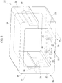
Figure 7 is a perspective view illustrating a variant ofFigure 1 . - It will be appreciated that, for clarity and simplicity of illustration, the various figures may not be reproduced on the same scale.
- In the following description various specific details are illustrated aimed at a thorough understanding of examples of one or more embodiments. The embodiments can be implemented without one or more of the specific details, or with other methods, components, materials, etc. In other cases, known structures, materials, or operations are not shown or described in detail to avoid obscuring various aspects of the embodiments. The reference to "an embodiment" in the context of this description indicates that a particular configuration, structure or characteristic described in relation to the embodiment is included in at least one embodiment. Therefore, phrases such as "in an embodiment", possibly present in different places of this description do not necessarily refer to the same embodiment. Moreover, particular conformations, structures or characteristics can be combined in any suitable manner in one or more embodiments and/or associated with the embodiments in a different way from that illustrated here, for example, a characteristic exemplified here in relation to a figure may be applied to one or more embodiments exemplified in a different figure.
- The references used here are only for convenience and do not therefore define the field of protection or the scope of the embodiments.
- In
Figures 1 and2 , thereference 10 indicates a connector for alinear lighting device 12. Thelinear lighting device 12 may comprise a plurality of solid state light radiation sources (SSL), for example, LED sources. Thelighting device 12 may have an outer coating of polymeric material which gives thelighting device 12 an IP degree of protection, for example IP6X. Theconnector 10 can be inserted at dedicated connection areas distributed along the length of thelinear lighting device 12. - In one or more embodiments, the
connector 10 may comprise afirst connector part 14 and asecond connector part 16. In one or more embodiments, thefirst connector part 14 and thesecond connector part 16 can be C-shaped, and can be applied to opposite sides of thelinear lighting device 12. Thefirst connector part 14 and thesecond connector part 16 may be provided with mutually cooperating snap-engagement formations, which may allow snap-fastening of thefirst connector portion 14 to thesecond connector portion 16. In one or more embodiments, the snap-engagement formations may comprise a pair ofteeth 18 protruding from a connector part, for example, from thefirst connector part 14, which snap-engage corresponding seats formed in the other connector part, for example, in thesecond connector part 16. - In one or more embodiments, the
first connector part 14 may have abase wall 20 and twoside walls 22, arranged according to a general C-shape. Theside walls 22 may be perpendicular to thebase wall 20. In one or more embodiments, thesecond connector part 16 may have a shape similar to that of thefirst connector part 14, with abase wall 24 and twoside walls 26. In one or more embodiments, theside walls 22 of thefirst connector part 14 and theside walls 26 of thesecond connector part 16 may have respective front surfaces in contact with each other. In one or more embodiments, the snap-engagement teeth 18 may protrude from the front surfaces of the side walls of thefirst connector part 14 and may snap-engage corresponding openings formed in theside walls 26 of thesecond connector part 16. - In one or more embodiments, in the condition in which the two
connector parts connector 10 may have a general O-shape, with a central through-opening through which thelinear lighting device 12 can extend. The snap connection between the twoconnector parts connector 10 on thelinear lighting device 12. In one or more embodiments, it may be possible to ensure an adequate IP degree of protection, for example, IP6X. The twoconnector parts - In one or more embodiments, the
first connector part 14 can be applied to the lower part of thelinear lighting device 12, with thebase wall 20 resting on the lower surface of thelinear lighting device 12 and theside walls 22 located along opposite sides of thelinear lighting device 12. Thesecond connector part 16 can be placed on the upper part of thelinear lighting device 12. The terms "lower" and "upper" only refer to the position illustrated in the figures and do not concern the assembled position of use of thelighting device 12. The part of thelighting device 12 indicated as "upper part" can be the part from which the light radiation is emitted. - With reference to
Figure 2 , the connector may comprise at least one connectingpin 28. In one or more embodiments, the connectingpin 28 may protrude from the inner surface of thefirst connector part 14. In one or more embodiments, said at least one connectingpin 28 may protrude from an inner surface of thebase wall 20 of thefirst connector part 14. - In one or more embodiments, the
connector 10 may comprise a plurality of connecting pins 28. In the illustrated example, theconnector 10 may comprise two connectingpins 28. In one or more embodiments, theconnector 10 may comprise 4, 5, 6 or even moreconnecting pins 28, so that theconnector 10 can be coupled to adjustable white, RGB, or RGBW lighting devices. - In one or more embodiments the connecting
pins 28 can be pointed and can perforate the outer insulating coating of thelinear lighting device 12 when the twocasing parts linear lighting device 12 and establish an electrical connection with conductive portions of thelighting device 12 located inside the outer insulating coating. - Again with reference to
Figure 2 , in one or more embodiments, theconnector 10 may comprise at least oneconductive element 30 electrically connected to at least one connectingpin 28. In one or more embodiments, said at least oneconductive element 30 can be contained within the thickness T of saidfirst connector part 14. - Said at least one
conductive element 30 can electrically connect said at least one connectingpin 28 with at least one electrical connection point, formed for example, by a terminal 32. In one or more embodiments, saidterminal 32 can be formed by a front surface of theconductive element 30. In one or more embodiments, saidterminal 32 of saidconductive element 30 can be located on an outer surface of aside wall 22 of aconnector part 14. - In one or more embodiments, the
connector 10 may comprise a plurality ofconductive elements 30. The number ofconductive elements 30 can be equal to the number of connecting pins 28. - In one or more embodiments, the
conductive elements 30 can be formed of metal strips. In one or more embodiments, the conductive elements can be made in the form of a metal frame. - In one or more embodiments, the plastic material forming the body of the
first connector part 14 can be co-molded onto said at least oneconductive element 30, so that said at least one conductive element may remain incorporated within the molded plastic material. - In one or more embodiments, said at least one
conductive element 30 can be housed within a respective groove formed in the plastic body of thefirst connector part 14. - The electrical connection between the connecting
pins 28 and therespective terminals 32 is not formed by electric cables (as in the solutions according to the prior art). The solution withconductive elements 30 co-molded inside the body of therespective connector part 14 or inserted into grooves formed in therespective connector part 14 can enable a strong reduction in the dimensions of theconnector 10, especially in its thickness T, given that theconductive elements 30 can be contained within the thickness T. The solution that envisages co-molding of theconductive elements 30 inside the body of theconnector part 14 may allow the production ofconnectors 10 with IP protection. The solution in which theconductive elements 30, for example, in the form of strips or metal plates, can be housed within respective grooves or cavities, can be used in the case where it is not necessary to obtain an IP protection. - With reference to
Figure 3 , in one or more embodiments the inner surface of thebase wall 20 of thefirst connector part 14 may have at least onecircular rib 34 surrounding said at least one connectingpin 28. Therib 34 can form a sealing gasket which can cooperate with a surface of thelinear lighting device 12 in order to provide IP protection. - In one or more embodiments, the
conductive elements 30 of theconnector 10 can be connected to an electricalpower supply cable 36. Thepower supply cable 36 can be a single cable, or may be formed of a plurality of independent electric wires. In one or more embodiments, the electrical connection between theconductive elements 30 and the electricalpower supply cable 36 can be implemented in one of the following ways: - 1) the ends of the
power supply cable 36 can be welded directly to the respectiveconductive elements 30, and the welding zones can then be molded inside the plastic material forming the body of the respective connector part 14 (Figure 1 ); - 2) the ends of the
power supply cable 36 can be crimped onto theconductive elements 30 at crimping points 38 (Figure 6 ), and the crimpingpoints 38 can be incorporated inside the plastic material forming the body of therespective connector part 14; - 3) the
terminals 32 of theconductive elements 30 can be exposed on the outer surface of the side wall 22 (Figure 4 ); the connection of the electrical power supply cable 36 - in this case - can be carried out directly by the end user, for example, by means of welding and filling material 40 (Figure 5 ) (for example, silicone), which can be applied to acavity 41 of theside wall 22 for covering the welding zones and providing the required IP degree of protection. - In one or more embodiments, the volume due to the connections with the electrical
power supply cables 36 can be formed on one side of theconnector 10. In this way, the thickness of theconnector 10 on the part intended to be applied on the lower part of thelighting device 12 can be minimal, and the ripple effect on a planar installation of thelinear lighting device 12 due to the presence of the connector can also be minimal. - In one or more embodiments, one or both of the
connector parts 14 may be formed of transparent material in order to minimize the visibility of theconnector 10. - As illustrated in
Figure 7 , in one or more embodiments, theconnector 10 can be applied to thelinear lighting device 12 in an overturned condition with respect to the one shown inFigure 1 , with theconnector part 14 carrying the connectingpins 28 located on the upper part of thelinear lighting device 12. Theconnector part 14 carrying the connectingpins 28 could - in this case - be made of transparent material to minimize the visibility of the connector. - One or more embodiments may have one or more of the following advantages:
- thanks to the reduced dimensions of the connector, especially below the linear lighting device, the connector does not bend the linear lighting device when the system is installed on a flat surface;
- the connector can be applied along flexible linear lighting devices with IP protection, even in the case of lighting devices with more than two poles, for example, it is possible to connect the connector to linear RGB, adjustable white and RGBW lighting devices;
- the connector is easy to install and has a pleasing appearance because the cross-sectional dimensions of the connector are substantially similar to the cross-sectional dimensions of the linear lighting device;
- the connector may be compatible for mounting on the upper or lower part of the linear lighting device (existing linear lighting devices with connecting areas on the upper surface of the device are compatible with the connection from above);
- the connector can be lightweight and compact so that no large spaces need to be reserved during its installation;
- the lighting device can be cut to the required length, and the connector can also be connected to scrap pieces;
- the connector can guarantee sufficient mechanical retention by means of the mutual fastening of the two connector parts;
- the connector can guarantee a required IP degree of protection.
- One or more embodiments can, therefore, concern a connector for linear lighting devices, comprising:
- a first and a second C-shaped connector part (e.g. 14, 16), which can be snap-engaged with each other,
- at least one connecting pin (e.g. 28) protruding from an inner surface of one of said connector parts (e.g. 14),
- at least one conductive element (e.g. 30) contained within the thickness (e.g. T) of said connector part (e.g. 14) and electrically connecting said at least one connecting pin (e.g. 28) to a connection point (e.g. 32, 38) with a power supply cable (e.g. 36).
- In one or more embodiments, said connector part (e.g. 14) can have a base wall (e.g. 20) and two side walls (e.g. 22) arranged according to a C-shape, said at least one connecting pin (e.g. 28) may protrude from an inner surface of said base wall (e.g. 20) and said electrical connection point (e.g. 32, 38) can be located on one of said side walls (e.g. 22).
- In one or more embodiments, a plastic material forming said connector part (e.g. 14) can be co-molded onto said conductive element (e.g. 30).
- In one or more embodiments, said at least one conductive element (e.g. 30) can be housed within a respective groove formed in said first connector part (e.g. 14).
- In one or more embodiments, said at least one conductive element (e.g. 30) can be welded to one end of a respective electrical power supply cable (e.g. 36).
- In one or more embodiments, a welding zone between said at least one conductive element (e.g. 30) and the end of the respective power supply cable (e.g. 36) can be co-molded inside said first connector part (e.g. 14).
- In one or more embodiments, said at least one conductive element (e.g. 30) can be crimped onto one end of a respective electrical power supply cable (e.g. 36).
- In one or more embodiments, a crimping zone (e.g.38) between said conductive element (e.g. 30) and the end of the respective electrical power supply cable (e.g. 36) can be co-molded inside said first connector part (e.g. 14).
- In one or more embodiments, one end (e.g. 32) of said at least one conductive element (e.g. 30) may be exposed on an outer surface of a side wall (e.g. 22) of said first connector part (e.g. 14).
- In one or more embodiments said at least one conductive element (e.g. 30) can be formed of a metal strip.
- In one or more embodiments at least one of said first and second connector parts (e.g. 14, 16) can be made of transparent material.
- In one or more embodiments, an inner surface of said first connector part (e.g. 14) may have at least one circular integral rib (e.g. 34) surrounding said at least one connecting pin (e.g. 28), and forming a sealing gasket.
- In one or more embodiments, the connector may comprise a plurality of connecting pins (e.g. 28) protruding from said inner surface of said first connector part (e.g. 14), and electrically connected to respective electrical connection points (e.g. 32, 38) through respective conductive elements (e.g. 30).
- One or more embodiments may concern a lighting system comprising a linear lighting device (e.g. 12) and a connector according to one or more embodiments applied along the length of said linear lighting device (e.g. 12).
- Of course, without prejudice to the underlying principles of the invention, the details of construction and the embodiments may vary, even significantly, with respect to those illustrated here, purely by way of non-limiting example, without departing from the scope of the invention.
- This field of protection is defined by the attached claims.
LIST OF REFERENCE SIGNS connector 10 linear lighting device 12 first connector part 14 second connector part 16 teeth 18 base wall 20 side walls 22 base wall 24 side walls 26 connecting pin 28 conductive element 30 terminal 32 circular rib 34 power supply cable 36 crimping points 38 filling material 40 cavity 41
Claims (14)
- A connector for linear lighting devices, comprising:- a first and a second C-shaped connector part (14, 16), which can be snap-engaged with each other,- at least one connecting pin (28) protruding from an inner surface of one of said connector parts (14),- at least one conductive element (30) contained within the thickness (T) of said connector part (14), and electrically connecting said at least one connecting pin (28) to a connection point (32, 38) with a power supply cable (36).
- A connector according to claim 1, wherein said connector part (14) has a base wall (20) and two side walls (22) arranged according to a C shape, wherein said at least one connecting pin (28) protrudes from an inner surface of said base wall (20) and wherein said electrical connection point (32, 38) is located on one of said side walls (22).
- A connector according to claim 1 or claim 2, wherein a plastic material forming said connector part (14) is co-molded onto said at least one conductive element (30).
- A connector according to claim 1 or claim 2, wherein said at least one conductive element (30) is housed within a respective groove formed in said first connector part (14).
- A connector according to any of the preceding claims, wherein said at least one conductive element (30) is welded to one end of a respective power supply cable (36).
- A connector according to claim 5, wherein a welding zone between said at least one conductive element (30) and the end of the respective power supply cable (36) is co-molded inside said first connector part (14).
- A connector according to any one of claims 1 to 4, wherein said at least one conductive element (30) is crimped on one end of a respective power supply cable (36) .
- A connector according to claim 7, wherein the crimping zone (38) between said at least one conductive element (30) and the end of the respective power supply cable (36) is co-molded inside said first connector part (14).
- A connector according to any of claims 1-4, wherein one end (32) of said at least one conductive element (30) is exposed on an outer surface of a side wall (22) of said first connector part (14).
- A connector according to any of the preceding claims, wherein said at least one conductive element (30) is formed by a metal strip.
- A connector according to any of the preceding claims, wherein at least one of said first and second connector parts (14, 16) is made of transparent material.
- A connector according to any one of the preceding claims, wherein an inner surface of said first connector part (14) has at least one circular integral rib (34) surrounding said at least one connecting pin (28) and forming a sealing gasket.
- A connector according to any of the preceding claims, comprising a plurality of connecting pins (28) protruding from said inner surface of said first connector part (14) and electrically connected to respective electrical connection points (32, 38) through respective conductive elements (30).
- A lighting system comprising a linear lighting device (12) and a connector according to one or more of the preceding claims applied along the length of said linear lighting device (12).
Applications Claiming Priority (1)
| Application Number | Priority Date | Filing Date | Title |
|---|---|---|---|
| IT201800000192 | 2018-01-02 |
Publications (2)
| Publication Number | Publication Date |
|---|---|
| EP3506434A1 true EP3506434A1 (en) | 2019-07-03 |
| EP3506434B1 EP3506434B1 (en) | 2021-03-24 |
Family
ID=61873814
Family Applications (1)
| Application Number | Title | Priority Date | Filing Date |
|---|---|---|---|
| EP18214443.6A Active EP3506434B1 (en) | 2018-01-02 | 2018-12-20 | A connector for linear lighting devices and linear lighting system comprising this connector |
Country Status (1)
| Country | Link |
|---|---|
| EP (1) | EP3506434B1 (en) |
Cited By (1)
| Publication number | Priority date | Publication date | Assignee | Title |
|---|---|---|---|---|
| DE102020105141A1 (en) | 2020-02-27 | 2021-09-02 | Aspöck Systems GmbH | Connection connecting element for a light-emitting diode strip |
Citations (5)
| Publication number | Priority date | Publication date | Assignee | Title |
|---|---|---|---|---|
| EP0283013A2 (en) * | 1987-03-18 | 1988-09-21 | Sumitomo Electric Industries Limited | Terminal arrangement for use in a multiplex transmission system |
| WO1994024728A1 (en) * | 1993-04-14 | 1994-10-27 | Siemens Aktiengesellschaft | Snap-on connector for electric lines |
| EP0734108A2 (en) * | 1995-03-23 | 1996-09-25 | IDL Industrie- und Design Licht GmbH | Lighting conductor rail system |
| EP3104060A1 (en) * | 2015-06-11 | 2016-12-14 | OSRAM GmbH | A connector for lighting devices and corresponding method |
| US9647349B1 (en) * | 2016-06-02 | 2017-05-09 | Elemental LED, Inc. | Through-insulation strip light connector |
-
2018
- 2018-12-20 EP EP18214443.6A patent/EP3506434B1/en active Active
Patent Citations (5)
| Publication number | Priority date | Publication date | Assignee | Title |
|---|---|---|---|---|
| EP0283013A2 (en) * | 1987-03-18 | 1988-09-21 | Sumitomo Electric Industries Limited | Terminal arrangement for use in a multiplex transmission system |
| WO1994024728A1 (en) * | 1993-04-14 | 1994-10-27 | Siemens Aktiengesellschaft | Snap-on connector for electric lines |
| EP0734108A2 (en) * | 1995-03-23 | 1996-09-25 | IDL Industrie- und Design Licht GmbH | Lighting conductor rail system |
| EP3104060A1 (en) * | 2015-06-11 | 2016-12-14 | OSRAM GmbH | A connector for lighting devices and corresponding method |
| US9647349B1 (en) * | 2016-06-02 | 2017-05-09 | Elemental LED, Inc. | Through-insulation strip light connector |
Cited By (1)
| Publication number | Priority date | Publication date | Assignee | Title |
|---|---|---|---|---|
| DE102020105141A1 (en) | 2020-02-27 | 2021-09-02 | Aspöck Systems GmbH | Connection connecting element for a light-emitting diode strip |
Also Published As
| Publication number | Publication date |
|---|---|
| EP3506434B1 (en) | 2021-03-24 |
Similar Documents
| Publication | Publication Date | Title |
|---|---|---|
| US9379477B2 (en) | Seal having a packing portion extending from a flat portion with a step | |
| US10763600B2 (en) | Connector structure | |
| US9997860B1 (en) | Coverplate and method for electrical outlet | |
| US6045374A (en) | Electrical wiring system | |
| US9837740B2 (en) | Electrical connector | |
| US10819071B2 (en) | Connector structure that is reconfigurable to accommodate either an STP cable or a UTP cable | |
| CN112425006B (en) | Electrical connector for receiving different sealing configurations | |
| US11705672B2 (en) | Plug-in connector with ground terminal region | |
| US11664621B2 (en) | Connector and connector with electric wires including the connector | |
| US20170170576A1 (en) | Lighted electrical connector housing | |
| EP3104060B1 (en) | An assembly comprising a connector and lighting devices and corresponding method | |
| EP3575672B1 (en) | Electrical connection module and lamp assembly | |
| US10020618B2 (en) | Shield case and connector provided with same | |
| EP4345366B1 (en) | Strip-shaped lamp and end cover for such a strip-shaped lamp | |
| JP5882128B2 (en) | Wire connection structure | |
| EP3506434B1 (en) | A connector for linear lighting devices and linear lighting system comprising this connector | |
| WO2013137483A1 (en) | Illuminating unit | |
| US20200350703A1 (en) | Wire connector | |
| CN104919662B (en) | Multipole jack, method for manufacturing same and electronic device | |
| US3656091A (en) | Terminal junction system | |
| KR100934421B1 (en) | Wire connecting device and wire connecting method using same | |
| KR101479544B1 (en) | Lighting apparatus using led | |
| US8109788B1 (en) | Cable assembly with improved grounding bar | |
| JP2004022520A (en) | Sealing structure for electrical parts | |
| CN216529442U (en) | Power line end connector with improved welding structure |
Legal Events
| Date | Code | Title | Description |
|---|---|---|---|
| PUAI | Public reference made under article 153(3) epc to a published international application that has entered the european phase |
Free format text: ORIGINAL CODE: 0009012 |
|
| STAA | Information on the status of an ep patent application or granted ep patent |
Free format text: STATUS: THE APPLICATION HAS BEEN PUBLISHED |
|
| AK | Designated contracting states |
Kind code of ref document: A1 Designated state(s): AL AT BE BG CH CY CZ DE DK EE ES FI FR GB GR HR HU IE IS IT LI LT LU LV MC MK MT NL NO PL PT RO RS SE SI SK SM TR |
|
| AX | Request for extension of the european patent |
Extension state: BA ME |
|
| STAA | Information on the status of an ep patent application or granted ep patent |
Free format text: STATUS: REQUEST FOR EXAMINATION WAS MADE |
|
| 17P | Request for examination filed |
Effective date: 20191212 |
|
| RBV | Designated contracting states (corrected) |
Designated state(s): AL AT BE BG CH CY CZ DE DK EE ES FI FR GB GR HR HU IE IS IT LI LT LU LV MC MK MT NL NO PL PT RO RS SE SI SK SM TR |
|
| RAP1 | Party data changed (applicant data changed or rights of an application transferred) |
Owner name: OSRAM GMBH Owner name: OSRAM S.P.A. - SOCIETA' RIUNITE OSRAM EDISON CLERICI |
|
| GRAP | Despatch of communication of intention to grant a patent |
Free format text: ORIGINAL CODE: EPIDOSNIGR1 |
|
| STAA | Information on the status of an ep patent application or granted ep patent |
Free format text: STATUS: GRANT OF PATENT IS INTENDED |
|
| RIC1 | Information provided on ipc code assigned before grant |
Ipc: H01R 13/506 20060101ALN20201112BHEP Ipc: H01R 4/2404 20180101ALN20201112BHEP Ipc: F21V 21/002 20060101ALN20201112BHEP Ipc: F21V 23/06 20060101ALN20201112BHEP Ipc: F21Y 103/10 20160101ALN20201112BHEP Ipc: H01R 11/20 20060101AFI20201112BHEP Ipc: F21Y 115/10 20160101ALN20201112BHEP Ipc: H01R 103/00 20060101ALN20201112BHEP Ipc: F21S 4/22 20160101ALI20201112BHEP Ipc: H01R 12/67 20110101ALI20201112BHEP |
|
| RIC1 | Information provided on ipc code assigned before grant |
Ipc: F21V 23/06 20060101ALN20201119BHEP Ipc: F21S 4/22 20160101ALI20201119BHEP Ipc: F21V 21/002 20060101ALN20201119BHEP Ipc: H01R 12/67 20110101ALI20201119BHEP Ipc: H01R 4/2404 20180101ALN20201119BHEP Ipc: H01R 103/00 20060101ALN20201119BHEP Ipc: H01R 13/506 20060101ALN20201119BHEP Ipc: F21Y 115/10 20160101ALN20201119BHEP Ipc: F21Y 103/10 20160101ALN20201119BHEP Ipc: H01R 11/20 20060101AFI20201119BHEP |
|
| INTG | Intention to grant announced |
Effective date: 20201201 |
|
| GRAS | Grant fee paid |
Free format text: ORIGINAL CODE: EPIDOSNIGR3 |
|
| GRAA | (expected) grant |
Free format text: ORIGINAL CODE: 0009210 |
|
| STAA | Information on the status of an ep patent application or granted ep patent |
Free format text: STATUS: THE PATENT HAS BEEN GRANTED |
|
| AK | Designated contracting states |
Kind code of ref document: B1 Designated state(s): AL AT BE BG CH CY CZ DE DK EE ES FI FR GB GR HR HU IE IS IT LI LT LU LV MC MK MT NL NO PL PT RO RS SE SI SK SM TR |
|
| REG | Reference to a national code |
Ref country code: GB Ref legal event code: FG4D |
|
| REG | Reference to a national code |
Ref country code: CH Ref legal event code: EP |
|
| RAP4 | Party data changed (patent owner data changed or rights of a patent transferred) |
Owner name: OSRAM S.P.A. - SOCIETA' RIUNITE OSRAM EDISON CLERICI Owner name: OSRAM GMBH |
|
| REG | Reference to a national code |
Ref country code: IE Ref legal event code: FG4D |
|
| REG | Reference to a national code |
Ref country code: AT Ref legal event code: REF Ref document number: 1375446 Country of ref document: AT Kind code of ref document: T Effective date: 20210415 Ref country code: DE Ref legal event code: R096 Ref document number: 602018014334 Country of ref document: DE |
|
| REG | Reference to a national code |
Ref country code: LT Ref legal event code: MG9D |
|
| PG25 | Lapsed in a contracting state [announced via postgrant information from national office to epo] |
Ref country code: NO Free format text: LAPSE BECAUSE OF FAILURE TO SUBMIT A TRANSLATION OF THE DESCRIPTION OR TO PAY THE FEE WITHIN THE PRESCRIBED TIME-LIMIT Effective date: 20210624 Ref country code: HR Free format text: LAPSE BECAUSE OF FAILURE TO SUBMIT A TRANSLATION OF THE DESCRIPTION OR TO PAY THE FEE WITHIN THE PRESCRIBED TIME-LIMIT Effective date: 20210324 Ref country code: FI Free format text: LAPSE BECAUSE OF FAILURE TO SUBMIT A TRANSLATION OF THE DESCRIPTION OR TO PAY THE FEE WITHIN THE PRESCRIBED TIME-LIMIT Effective date: 20210324 Ref country code: GR Free format text: LAPSE BECAUSE OF FAILURE TO SUBMIT A TRANSLATION OF THE DESCRIPTION OR TO PAY THE FEE WITHIN THE PRESCRIBED TIME-LIMIT Effective date: 20210625 Ref country code: BG Free format text: LAPSE BECAUSE OF FAILURE TO SUBMIT A TRANSLATION OF THE DESCRIPTION OR TO PAY THE FEE WITHIN THE PRESCRIBED TIME-LIMIT Effective date: 20210624 |
|
| PG25 | Lapsed in a contracting state [announced via postgrant information from national office to epo] |
Ref country code: SE Free format text: LAPSE BECAUSE OF FAILURE TO SUBMIT A TRANSLATION OF THE DESCRIPTION OR TO PAY THE FEE WITHIN THE PRESCRIBED TIME-LIMIT Effective date: 20210324 Ref country code: RS Free format text: LAPSE BECAUSE OF FAILURE TO SUBMIT A TRANSLATION OF THE DESCRIPTION OR TO PAY THE FEE WITHIN THE PRESCRIBED TIME-LIMIT Effective date: 20210324 Ref country code: LV Free format text: LAPSE BECAUSE OF FAILURE TO SUBMIT A TRANSLATION OF THE DESCRIPTION OR TO PAY THE FEE WITHIN THE PRESCRIBED TIME-LIMIT Effective date: 20210324 |
|
| REG | Reference to a national code |
Ref country code: NL Ref legal event code: MP Effective date: 20210324 |
|
| REG | Reference to a national code |
Ref country code: AT Ref legal event code: MK05 Ref document number: 1375446 Country of ref document: AT Kind code of ref document: T Effective date: 20210324 |
|
| PG25 | Lapsed in a contracting state [announced via postgrant information from national office to epo] |
Ref country code: NL Free format text: LAPSE BECAUSE OF FAILURE TO SUBMIT A TRANSLATION OF THE DESCRIPTION OR TO PAY THE FEE WITHIN THE PRESCRIBED TIME-LIMIT Effective date: 20210324 |
|
| PG25 | Lapsed in a contracting state [announced via postgrant information from national office to epo] |
Ref country code: AT Free format text: LAPSE BECAUSE OF FAILURE TO SUBMIT A TRANSLATION OF THE DESCRIPTION OR TO PAY THE FEE WITHIN THE PRESCRIBED TIME-LIMIT Effective date: 20210324 Ref country code: SM Free format text: LAPSE BECAUSE OF FAILURE TO SUBMIT A TRANSLATION OF THE DESCRIPTION OR TO PAY THE FEE WITHIN THE PRESCRIBED TIME-LIMIT Effective date: 20210324 Ref country code: EE Free format text: LAPSE BECAUSE OF FAILURE TO SUBMIT A TRANSLATION OF THE DESCRIPTION OR TO PAY THE FEE WITHIN THE PRESCRIBED TIME-LIMIT Effective date: 20210324 Ref country code: CZ Free format text: LAPSE BECAUSE OF FAILURE TO SUBMIT A TRANSLATION OF THE DESCRIPTION OR TO PAY THE FEE WITHIN THE PRESCRIBED TIME-LIMIT Effective date: 20210324 Ref country code: LT Free format text: LAPSE BECAUSE OF FAILURE TO SUBMIT A TRANSLATION OF THE DESCRIPTION OR TO PAY THE FEE WITHIN THE PRESCRIBED TIME-LIMIT Effective date: 20210324 |
|
| PG25 | Lapsed in a contracting state [announced via postgrant information from national office to epo] |
Ref country code: IS Free format text: LAPSE BECAUSE OF FAILURE TO SUBMIT A TRANSLATION OF THE DESCRIPTION OR TO PAY THE FEE WITHIN THE PRESCRIBED TIME-LIMIT Effective date: 20210724 Ref country code: PT Free format text: LAPSE BECAUSE OF FAILURE TO SUBMIT A TRANSLATION OF THE DESCRIPTION OR TO PAY THE FEE WITHIN THE PRESCRIBED TIME-LIMIT Effective date: 20210726 Ref country code: PL Free format text: LAPSE BECAUSE OF FAILURE TO SUBMIT A TRANSLATION OF THE DESCRIPTION OR TO PAY THE FEE WITHIN THE PRESCRIBED TIME-LIMIT Effective date: 20210324 Ref country code: RO Free format text: LAPSE BECAUSE OF FAILURE TO SUBMIT A TRANSLATION OF THE DESCRIPTION OR TO PAY THE FEE WITHIN THE PRESCRIBED TIME-LIMIT Effective date: 20210324 Ref country code: SK Free format text: LAPSE BECAUSE OF FAILURE TO SUBMIT A TRANSLATION OF THE DESCRIPTION OR TO PAY THE FEE WITHIN THE PRESCRIBED TIME-LIMIT Effective date: 20210324 |
|
| REG | Reference to a national code |
Ref country code: DE Ref legal event code: R097 Ref document number: 602018014334 Country of ref document: DE |
|
| PG25 | Lapsed in a contracting state [announced via postgrant information from national office to epo] |
Ref country code: ES Free format text: LAPSE BECAUSE OF FAILURE TO SUBMIT A TRANSLATION OF THE DESCRIPTION OR TO PAY THE FEE WITHIN THE PRESCRIBED TIME-LIMIT Effective date: 20210324 Ref country code: AL Free format text: LAPSE BECAUSE OF FAILURE TO SUBMIT A TRANSLATION OF THE DESCRIPTION OR TO PAY THE FEE WITHIN THE PRESCRIBED TIME-LIMIT Effective date: 20210324 Ref country code: DK Free format text: LAPSE BECAUSE OF FAILURE TO SUBMIT A TRANSLATION OF THE DESCRIPTION OR TO PAY THE FEE WITHIN THE PRESCRIBED TIME-LIMIT Effective date: 20210324 |
|
| PLBE | No opposition filed within time limit |
Free format text: ORIGINAL CODE: 0009261 |
|
| STAA | Information on the status of an ep patent application or granted ep patent |
Free format text: STATUS: NO OPPOSITION FILED WITHIN TIME LIMIT |
|
| PG25 | Lapsed in a contracting state [announced via postgrant information from national office to epo] |
Ref country code: SI Free format text: LAPSE BECAUSE OF FAILURE TO SUBMIT A TRANSLATION OF THE DESCRIPTION OR TO PAY THE FEE WITHIN THE PRESCRIBED TIME-LIMIT Effective date: 20210324 |
|
| 26N | No opposition filed |
Effective date: 20220104 |
|
| PG25 | Lapsed in a contracting state [announced via postgrant information from national office to epo] |
Ref country code: IS Free format text: LAPSE BECAUSE OF FAILURE TO SUBMIT A TRANSLATION OF THE DESCRIPTION OR TO PAY THE FEE WITHIN THE PRESCRIBED TIME-LIMIT Effective date: 20210724 |
|
| PG25 | Lapsed in a contracting state [announced via postgrant information from national office to epo] |
Ref country code: MC Free format text: LAPSE BECAUSE OF FAILURE TO SUBMIT A TRANSLATION OF THE DESCRIPTION OR TO PAY THE FEE WITHIN THE PRESCRIBED TIME-LIMIT Effective date: 20210324 |
|
| REG | Reference to a national code |
Ref country code: CH Ref legal event code: PL |
|
| REG | Reference to a national code |
Ref country code: BE Ref legal event code: MM Effective date: 20211231 |
|
| PG25 | Lapsed in a contracting state [announced via postgrant information from national office to epo] |
Ref country code: LU Free format text: LAPSE BECAUSE OF NON-PAYMENT OF DUE FEES Effective date: 20211220 Ref country code: IE Free format text: LAPSE BECAUSE OF NON-PAYMENT OF DUE FEES Effective date: 20211220 |
|
| PG25 | Lapsed in a contracting state [announced via postgrant information from national office to epo] |
Ref country code: FR Free format text: LAPSE BECAUSE OF NON-PAYMENT OF DUE FEES Effective date: 20211231 Ref country code: BE Free format text: LAPSE BECAUSE OF NON-PAYMENT OF DUE FEES Effective date: 20211231 |
|
| PG25 | Lapsed in a contracting state [announced via postgrant information from national office to epo] |
Ref country code: LI Free format text: LAPSE BECAUSE OF NON-PAYMENT OF DUE FEES Effective date: 20211231 Ref country code: CH Free format text: LAPSE BECAUSE OF NON-PAYMENT OF DUE FEES Effective date: 20211231 |
|
| PG25 | Lapsed in a contracting state [announced via postgrant information from national office to epo] |
Ref country code: IT Free format text: LAPSE BECAUSE OF FAILURE TO SUBMIT A TRANSLATION OF THE DESCRIPTION OR TO PAY THE FEE WITHIN THE PRESCRIBED TIME-LIMIT Effective date: 20210324 |
|
| REG | Reference to a national code |
Ref country code: DE Ref legal event code: R081 Ref document number: 602018014334 Country of ref document: DE Owner name: OPTOTRONIC GMBH, DE Free format text: FORMER OWNER: OSRAM GMBH, 80807 MUENCHEN, DE Ref country code: DE Ref legal event code: R081 Ref document number: 602018014334 Country of ref document: DE Owner name: INVENTRONICS GMBH, DE Free format text: FORMER OWNER: OSRAM GMBH, 80807 MUENCHEN, DE |
|
| PG25 | Lapsed in a contracting state [announced via postgrant information from national office to epo] |
Ref country code: CY Free format text: LAPSE BECAUSE OF FAILURE TO SUBMIT A TRANSLATION OF THE DESCRIPTION OR TO PAY THE FEE WITHIN THE PRESCRIBED TIME-LIMIT Effective date: 20210324 |
|
| PG25 | Lapsed in a contracting state [announced via postgrant information from national office to epo] |
Ref country code: HU Free format text: LAPSE BECAUSE OF FAILURE TO SUBMIT A TRANSLATION OF THE DESCRIPTION OR TO PAY THE FEE WITHIN THE PRESCRIBED TIME-LIMIT; INVALID AB INITIO Effective date: 20181220 |
|
| GBPC | Gb: european patent ceased through non-payment of renewal fee |
Effective date: 20221220 |
|
| PG25 | Lapsed in a contracting state [announced via postgrant information from national office to epo] |
Ref country code: GB Free format text: LAPSE BECAUSE OF NON-PAYMENT OF DUE FEES Effective date: 20221220 |
|
| PG25 | Lapsed in a contracting state [announced via postgrant information from national office to epo] |
Ref country code: MK Free format text: LAPSE BECAUSE OF FAILURE TO SUBMIT A TRANSLATION OF THE DESCRIPTION OR TO PAY THE FEE WITHIN THE PRESCRIBED TIME-LIMIT Effective date: 20210324 |
|
| REG | Reference to a national code |
Ref country code: DE Ref legal event code: R081 Ref document number: 602018014334 Country of ref document: DE Owner name: INVENTRONICS GMBH, DE Free format text: FORMER OWNER: OPTOTRONIC GMBH, 85748 GARCHING, DE |
|
| PG25 | Lapsed in a contracting state [announced via postgrant information from national office to epo] |
Ref country code: MT Free format text: LAPSE BECAUSE OF FAILURE TO SUBMIT A TRANSLATION OF THE DESCRIPTION OR TO PAY THE FEE WITHIN THE PRESCRIBED TIME-LIMIT Effective date: 20210324 |
|
| PG25 | Lapsed in a contracting state [announced via postgrant information from national office to epo] |
Ref country code: TR Free format text: LAPSE BECAUSE OF FAILURE TO SUBMIT A TRANSLATION OF THE DESCRIPTION OR TO PAY THE FEE WITHIN THE PRESCRIBED TIME-LIMIT Effective date: 20210324 |
|
| PGFP | Annual fee paid to national office [announced via postgrant information from national office to epo] |
Ref country code: DE Payment date: 20251222 Year of fee payment: 8 |