EP3506433A2 - Mechanical connecting element, electrical contact device and electrical connector - Google Patents
Mechanical connecting element, electrical contact device and electrical connector Download PDFInfo
- Publication number
- EP3506433A2 EP3506433A2 EP18215546.5A EP18215546A EP3506433A2 EP 3506433 A2 EP3506433 A2 EP 3506433A2 EP 18215546 A EP18215546 A EP 18215546A EP 3506433 A2 EP3506433 A2 EP 3506433A2
- Authority
- EP
- European Patent Office
- Prior art keywords
- connecting element
- region
- mechanical
- electrical
- cable
- Prior art date
- Legal status (The legal status is an assumption and is not a legal conclusion. Google has not performed a legal analysis and makes no representation as to the accuracy of the status listed.)
- Withdrawn
Links
- 238000003466 welding Methods 0.000 claims description 7
- 238000000034 method Methods 0.000 claims description 4
- 239000000758 substrate Substances 0.000 claims description 4
- 238000005304 joining Methods 0.000 claims description 2
- 239000000853 adhesive Substances 0.000 description 7
- 230000001070 adhesive effect Effects 0.000 description 7
- 230000013011 mating Effects 0.000 description 5
- 230000000295 complement effect Effects 0.000 description 3
- 241000826860 Trapezium Species 0.000 description 2
- 230000005540 biological transmission Effects 0.000 description 2
- 238000010586 diagram Methods 0.000 description 2
- 238000004870 electrical engineering Methods 0.000 description 2
- 239000000463 material Substances 0.000 description 2
- 238000005476 soldering Methods 0.000 description 2
- 238000001228 spectrum Methods 0.000 description 2
- 238000004026 adhesive bonding Methods 0.000 description 1
- 230000015572 biosynthetic process Effects 0.000 description 1
- 238000005266 casting Methods 0.000 description 1
- 230000008878 coupling Effects 0.000 description 1
- 238000010168 coupling process Methods 0.000 description 1
- 238000005859 coupling reaction Methods 0.000 description 1
- 230000002950 deficient Effects 0.000 description 1
- 230000001419 dependent effect Effects 0.000 description 1
- 230000000694 effects Effects 0.000 description 1
- 230000005611 electricity Effects 0.000 description 1
- 238000002955 isolation Methods 0.000 description 1
- 238000004519 manufacturing process Methods 0.000 description 1
- 238000012544 monitoring process Methods 0.000 description 1
- 239000007787 solid Substances 0.000 description 1
- 238000002604 ultrasonography Methods 0.000 description 1
Images
Classifications
-
- H—ELECTRICITY
- H01—ELECTRIC ELEMENTS
- H01R—ELECTRICALLY-CONDUCTIVE CONNECTIONS; STRUCTURAL ASSOCIATIONS OF A PLURALITY OF MUTUALLY-INSULATED ELECTRICAL CONNECTING ELEMENTS; COUPLING DEVICES; CURRENT COLLECTORS
- H01R4/00—Electrically-conductive connections between two or more conductive members in direct contact, i.e. touching one another; Means for effecting or maintaining such contact; Electrically-conductive connections having two or more spaced connecting locations for conductors and using contact members penetrating insulation
- H01R4/02—Soldered or welded connections
- H01R4/023—Soldered or welded connections between cables or wires and terminals
-
- H—ELECTRICITY
- H01—ELECTRIC ELEMENTS
- H01R—ELECTRICALLY-CONDUCTIVE CONNECTIONS; STRUCTURAL ASSOCIATIONS OF A PLURALITY OF MUTUALLY-INSULATED ELECTRICAL CONNECTING ELEMENTS; COUPLING DEVICES; CURRENT COLLECTORS
- H01R11/00—Individual connecting elements providing two or more spaced connecting locations for conductive members which are, or may be, thereby interconnected, e.g. end pieces for wires or cables supported by the wire or cable and having means for facilitating electrical connection to some other wire, terminal, or conductive member, blocks of binding posts
- H01R11/01—Individual connecting elements providing two or more spaced connecting locations for conductive members which are, or may be, thereby interconnected, e.g. end pieces for wires or cables supported by the wire or cable and having means for facilitating electrical connection to some other wire, terminal, or conductive member, blocks of binding posts characterised by the form or arrangement of the conductive interconnection between the connecting locations
-
- H—ELECTRICITY
- H01—ELECTRIC ELEMENTS
- H01R—ELECTRICALLY-CONDUCTIVE CONNECTIONS; STRUCTURAL ASSOCIATIONS OF A PLURALITY OF MUTUALLY-INSULATED ELECTRICAL CONNECTING ELEMENTS; COUPLING DEVICES; CURRENT COLLECTORS
- H01R11/00—Individual connecting elements providing two or more spaced connecting locations for conductive members which are, or may be, thereby interconnected, e.g. end pieces for wires or cables supported by the wire or cable and having means for facilitating electrical connection to some other wire, terminal, or conductive member, blocks of binding posts
- H01R11/03—Individual connecting elements providing two or more spaced connecting locations for conductive members which are, or may be, thereby interconnected, e.g. end pieces for wires or cables supported by the wire or cable and having means for facilitating electrical connection to some other wire, terminal, or conductive member, blocks of binding posts characterised by the relationship between the connecting locations
-
- H—ELECTRICITY
- H01—ELECTRIC ELEMENTS
- H01R—ELECTRICALLY-CONDUCTIVE CONNECTIONS; STRUCTURAL ASSOCIATIONS OF A PLURALITY OF MUTUALLY-INSULATED ELECTRICAL CONNECTING ELEMENTS; COUPLING DEVICES; CURRENT COLLECTORS
- H01R11/00—Individual connecting elements providing two or more spaced connecting locations for conductive members which are, or may be, thereby interconnected, e.g. end pieces for wires or cables supported by the wire or cable and having means for facilitating electrical connection to some other wire, terminal, or conductive member, blocks of binding posts
- H01R11/11—End pieces or tapping pieces for wires, supported by the wire and for facilitating electrical connection to some other wire, terminal or conductive member
- H01R11/16—End pieces terminating in a soldering tip or socket
-
- H—ELECTRICITY
- H01—ELECTRIC ELEMENTS
- H01R—ELECTRICALLY-CONDUCTIVE CONNECTIONS; STRUCTURAL ASSOCIATIONS OF A PLURALITY OF MUTUALLY-INSULATED ELECTRICAL CONNECTING ELEMENTS; COUPLING DEVICES; CURRENT COLLECTORS
- H01R4/00—Electrically-conductive connections between two or more conductive members in direct contact, i.e. touching one another; Means for effecting or maintaining such contact; Electrically-conductive connections having two or more spaced connecting locations for conductors and using contact members penetrating insulation
- H01R4/02—Soldered or welded connections
- H01R4/029—Welded connections
Definitions
- the invention relates to a mechanical connecting element for electromechanical connecting sections, in particular a retaining element for an adhesively bonded connection, preferably a welded connection, in particular for the motor vehicle sector.
- the invention further relates to an electrical contact device, an electrical component, an electrical connector, in particular a high-current connector, preferably a charging plug for the motor vehicle sector, a substrate, a printed circuit board, a device, a ready-made electrical cable, a module, an appliance, an apparatus or a system.
- Such a connector and possibly its housing can be fitted on an electrical cable, a wire, a cable harness etc. (ready-made electrical cable), or on/in an electrical device or apparatus, such as on/in a housing, to/on a pressed frame, to/on a printed circuit board etc., a (power) electrical, electro-optical or electronic component or such a unit (see below), etc.
- an electrical device or apparatus such as on/in a housing, to/on a pressed frame, to/on a printed circuit board etc., a (power) electrical, electro-optical or electronic component or such a unit (see below), etc.
- a connector with/without housing
- this is also known as a (flying) (plug) connector or a plug or a coupling
- a (mating) connector device such as a (built-in) connector, a (built-in) plug or a (built-in) socket.
- a connector on such a device is often also referred to as a (plug) receptacle or header.
- an electrical connecting device e.g. having or comprising a dedicated contact apparatus (mostly integral in form, e.g. a contact element, a terminal, etc.) or a contact device (mostly multi-piece, two-piece, monobloc, materially monobloc or integral, e.g. a one- or multi-piece (crimp) contact device), must be accommodated securely in this connector.
- a connecting device can be provided as a connector, therefore without a housing, e.g. flying.
- US 5 948 175 A ( DE 697 04 540 T2 ) and US 5 961 737 A ( DE 697 00 382 T2 ) each disclose, for a solar cell arrangement, mechanical clamping elements for electrical wires.
- the wire is fastened on an electrical terminal contact with the aid of the clamping element, the clamping element further being, on one hand, welded to the terminal contact at at least one location and, on the other hand, the wire being soldered to the clamping element and possibly to the terminal contact.
- the clamping element has, in sections, a u-shaped or o-shaped cross-section, through which a stripped longitudinal end section of the wire extends.
- the adhesively bonded connection, together with the element is intended to take up little space and to be able to be formed in a robust manner.
- a mechanical connecting element for electromechanical connecting sections in particular a retaining element for an adhesively bonded connection, preferably a welded connection, in particular for the motor vehicle sector; by means of an electrical contact device, an electrical component or an electrical cable; by means of an electrical connector, in particular a high-current connector, preferably a charging plug for the motor vehicle sector; and by means of a substrate, a printed circuit board, a device, a ready-made electrical cable, a module, an appliance, an apparatus or a system.
- the connecting element according to the invention (which can also be referred to as a retaining element) for electromechanical connecting sections, has two mechanical connecting regions for at least one connecting section distinct from the connecting element or for at least two connecting sections distinct from the connecting element, the two connecting regions being arranged above one another in the connecting element in such a way that the two connecting sections can be brought into direct electromechanical contact above one another in the connecting element.
- Such an adhesively bonded connection between e.g. an electrical contact device (connecting section) and an electrical cable (connecting section), within the connecting element can be formed e.g. as an adhesive, soldered or welded connection.
- the welded connection can be formed as an electro- (resistance) or ultrasound welded connection.
- the connecting element can comprise exactly two or at least two connecting regions.
- a plugging direction of the connecting element on the basis of a connecting region, and a plugging direction of a connecting section on the basis of the other connecting region onto/at/into the connecting element form an angle of between 0° and 360°, in particular an angle of 0°, 30°, 45°, 60°, 75° or 90°, in each case ⁇ 0° to ⁇ 5°.
- the connecting element itself further can have at least the other connecting section, wherein the connecting element is provided or formed in a one-piece, monobloc, materially monobloc or integral manner with the other connecting section.
- connecting element As a result of this, it is e.g. possible to supply the connecting element as one piece or monobloc, the connecting element already being plugged onto the other connecting section, e.g. an electrical contact device, an electrical component or even a cable. Further, it is possible to connect the connecting element to the connecting section in a materially monobloc manner (e.g. bonding, soldering, welding) or integrally with it (e.g. casting). As a result, there is produced a connecting element having a contact device, a component or a cable, which vice versa can be referred to as a contact device, component or cable having a connecting element.
- a (first) connecting region can be formed as a mechanical contact-connecting region of the connecting element for an electromechanical contact-connecting section of an electrical contact device.
- a (second) connecting region can be formed as a mechanical cable-connecting region of the connecting element for an electromechanical cable-connecting section of an electrical cable.
- the (first) connecting region or the contact-connecting region can be formed as a plugging connecting region, and/or the (second) connecting region or the cable-connecting region can be formed as a plugging connecting region.
- an associated plugging connecting region can be formed as a plug-in connecting region or a plug-on connecting region.
- the connecting element itself can be provided on/at/in the associated connecting section, e.g. the contact device.
- the connecting section e.g. of the cable, can be provided on/at/in the connecting element.
- the first connecting region or the contact-connecting region is formed as a plug-on connecting region for the connecting element and/or the second connecting region or the cable-connecting region can be formed as a plug-in connecting region into the connecting element.
- the connecting element can have a substantially basket-, cage-, sleeve-, or tube-shaped form, wherein in a first plane the first connecting region and, in a second plane spaced apart from the first plane, the second connecting region directly adjacent to the first connecting region are arranged in the connecting element.
- the connecting sections or their longitudinal middle lines can be arranged above one another in two planes spaced apart from one another and substantially parallel.
- an arrangement of the two connecting sections on substantially a common axis or of a common axis region, which is constituted by the longitudinal extents of the connecting sections, is in turn ruled out.
- the shell-like connecting element e.g. primarily configured as a basket, a cage, a sleeve or a tube, can be fastened (in one piece or in a monobloc manner) e.g. to a connecting section of a contact device or of a component, or is a materially one-piece or integral component of the contact device or of the component, to which the cable is to be attached; or vice versa, is thus a one-piece, monobloc, materially monobloc or integral component of the cable.
- the connecting element in its (end) mounting position, provides a solid mechanical connection to the relevant connecting sections (contact device and cable to be terminated, component and cable to be terminated, contact device and component, cable and cable etc.).
- the first connecting region can extend radially or laterally into an outer structure or an outer casing of the connecting element or extends through it.
- the second connecting region starting from a base area of the connecting element, can extend axially or in the longitudinal direction into the connecting element or extend through it.
- at least one connecting region can be connectable at least in a partially positive-locking and/or coded manner to an associated connecting section, a contact-connecting section or a cable-connecting section.
- a coding here can be implemented by means of two coding forms (connecting region and connecting section or contact-connecting section or cable-connecting section (cable termination)), which can be formed in a manner complementary to each other at least in sections.
- a corresponding cross-sectional design of a connecting section associated with a connecting region is suitable.
- Such a cross-section such as that of an equal-sided trapezium, can e.g. possess a single axis of symmetry. It is of course possible to use other cross-sections.
- the connecting element in a first aspect can be formed as a hollow cylinder having a substantially elliptical, a substantially oval, a substantially polygonal, e.g. rectangular, or a closed substantially u-shaped base area.
- the connecting element in a second aspect can have two through-recesses, which align with each other in the plugging direction of the connecting element, in the outer structure or outer casing thereof, which constitute the connecting region in the connecting element.
- the first aspect forms a 'rougher' perspective of the connecting element (e.g. leaving out the connecting region for a mounting of the connecting element) than the second aspect, in which the connecting element is considered in greater detail (e.g. taking into account the connecting region for the mounting of the connecting element).
- the connecting element (outer structure or outer casing etc.) can be shaped further in structural terms (perforation etc.).
- a closed u-shaped base area is understood to mean a limiting line, which is formed by a 'U', the free ends of both limbs of the 'U' being closed by means of a substantially straight connecting line (cf. Fig.).
- the through-recesses for constituting the connecting region preferably lie diametrically opposite each other.
- the through-recesses for constituting the connecting region lie in the vicinity of a comparatively less curved or straight side wall of the connecting element.
- the connecting element can be formed as an electromechanical connecting element, an adhesively bonded retaining element, and/or a double socket element.
- the connecting element can further be formed as a limiting element for adhesively bonded joining, in particular as a welding space limiting element.
- the connecting element can be formed in such a way that a welding process can be carried out through the outer structure or outer casing thereof.
- a sudden dropping-off of a connecting section is prevented, which otherwise is possibly not ascertainable. Furthermore, sudden failure of an electrical connection (dropping-off of a connecting section of the other connecting section corresponding thereto in a use of the electrical connection) can be prevented. Further, a comparatively thin connecting element can be used in comparison with the wall thicknesses of the main electrical components (connecting sections).
- the invention implements a redundant mechanical retaining or fixing in addition to an adhesively bonded connection, wherein a sudden loss of an electrical termination can be prevented.
- a comparatively slower loss of termination ((partially) defective termination by adhesive bond, but substantially intact termination by means of the connecting element) is not so critical, since a component, with its associated connecting section, can be subject to a thermal monitoring.
- the connecting element according to the invention can be constructed simply and is cost-effective in comparison with the cost-intensive crimp connections which, further, require a specific, comparatively large material thickness. The connecting element further saves more space than a crimp connection analogous thereto.
- the contact device according to the invention, the component according to the invention or the cable according to the invention has a mechanical connecting element according to the invention.
- the connecting element can be provided in an at least partially positive-locking and/or coded manner on/at/in an associated connecting section of the contact device, the component or the cable. Further, the connecting element can be locked to the associated connecting section.
- the connecting element can be provided in a one-piece or monobloc manner with the associated connecting section.
- the connecting element can be formed such that it is connected in a materially monobloc manner or is formed integrally with the associated connecting section.
- the connector according to the invention has a mechanical connecting element, which connects an electrical contact device of the connector and an electrical cable of the connector to each other, wherein the connecting element is formed according to the invention.
- the contact device can be a pin or socket contact device of the connector, the cable and the connecting element being provided away from an actual pin or socket contact apparatus of the pin or socket contact device.
- a provision can be understood to mean a (possibly loose) connection, a fastening (in one, two or three translatory and/or one, two or three rotatory spatial directions), a locking (in one, two or three translatory or one, two or three rotatory spatial directions), a fixing (clamping-in in all translatory and all rotatory spatial directions) etc.
- a feature can be configured to be positive, i.e. present, or negative, i.e. absent, with a negative feature not being explicitly explained as a feature if the fact that it is absent is not deemed to be significant according to the invention.
- a feature of this specification (description, list of reference numbers, claims, drawings) can be applied not only in a specified manner but rather can also be applied in a different manner (isolation, summary, replacement, addition, uniqueness, omission, etc.).
- a generic term for the feature can also be read alongside this, (optionally further hierarchical classification into subgenus, section, etc.), as a result of which it is possible to generalise a, or this, feature, e.g. taking into account identical effect and/or equivalence.
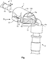
- the merely exemplary Fig. shows a three-dimensional view of an electrical contact device formed as an electrical pin contact (depicted broken away below) for a charging plug of a vehicle, having a connecting element according to the invention provided on its electromechanical connecting section.
- the invention can therefore be applied to other connectors, mating connectors (see above) or cables or cable harnesses in the motor vehicle sector or in a non-motor-vehicle sector, such as in an electronics, electrical engineering, power engineering sector, etc.
- the invention can also be applied e.g. to connecting devices, contact devices, contact apparatuses, cables or cable harnesses in the computer and (consumer) electronics sector.
- the Fig. shows an electrical contact device 2 having a dedicated contact apparatus (depicted broken away below) and an electrical or electromechanical connecting section 22.
- the contact device 2 is formed as a pin contact device 2 having a dedicated contact apparatus (depicted broken away below) and a contact-connecting section 22. It is of course possible to form the contact device 2 in other ways, e.g. to use a socket contact device, a tab contact device etc.
- the contact-connecting section 22 is at an approximately 90° angle away from the actual pin contact device 2. It is of course possible to form other angles here or to form the pin contact device 2 as a straight (180° angle) pin contact device 2.
- the contact-connecting section 22 has a cross-section which has the form of a substantially equal-sided trapezium. It is natural to use other cross-sections, which preferably allow a coding with the connecting element 1 according to the invention. Multiply symmetrical cross-sections, such as a rectangular cross-section, can of course likewise be used, in such a case the cross-section of the contact-connecting section 22 preferably having a coding form, which is formed in a manner complementary to a coding form of the connecting element 1 at least in sections.
- the connecting section 22 or the contact-connecting section 22 preferably has suitability for an adhesively bonded connection (bonding, soldering, welding etc.) to another connecting section 44.
- it is formed in a manner preferably level (in a plane) at an associated side.
- a formation complementary to the connecting section 44 at least in sections can be used likewise, for example.
- a longitudinal extent of the contact-connecting section 22 constitutes a plugging direction S 12 of the connecting element 1 on/at/in the contact-connecting section 22.
- the connecting section 22 is formed as a stripped cable-connecting section 44 of an electrical cable 4, a cable harness 4, a braid 4 etc. It is of course possible here to use another connecting section 22, e.g. that of an electrical component etc.
- the adhesive bond lies between the connecting sections 22, 44 within the connecting element 1 according to the invention, it being preferred to establish the adhesive bond only when the two connecting sections 22, 44 are located within the connecting element 1, for which purpose the connecting element 1 has a corresponding suitability (material, dimensions etc.).
- the mechanical or electromechanical connecting element 1 has in the present case, in one aspect, the form of a tube or a cylinder having a u-shaped, closed base area, the free ends of the two limbs of the 'U' being closed by means of a substantially straight connecting line (cf. Fig.).
- Other base areas ellipses, circles, rectangles, squares, polygons, composed cross-sections etc.
- a form of the connecting section 22 or of the contact-connecting section 22 can of course be used.
- a tube or such a cylinder e.g. a basket, a cage, a sleeve etc. can also be used as a form of the connecting element 1.
- the connecting element 1 is formed as a retaining element 1 for the adhesively bonded connection, preferably a welded connection, the connecting element 1 of the Fig. being formed as a double socket element 1.
- the connecting element 1 comprises an outer structure 10 or an outer casing 10, into which a mechanical or electromechanical, first connecting region 12 is fitted by means of through-recesses 120 (second aspect). Away from the first connecting region 12, the outer structure 10 or outer casing 10 forms a mechanical or electromechanical, second connecting region 14 of the connecting element 1. Apart from the two open base area sides and the two through-recesses 120, the connecting element 1 can be formed in a closed manner in the region of the outer structure 10 or the outer casing 10.
- the connecting region 12 is formed as a contact-connecting region 12 for the contact-connecting section 22 of the contact device 2
- the connecting region 14 is formed as a cable-connecting region 14 for the cable-connecting section 44 of the cable 4.
- both connecting regions 12, 14 are formed as plugging connecting regions 12, 14.
- the connecting region 12 as a plug-on connecting region 12 serves for plug-on mounting of the connecting element 1 on the connecting section 22 of the contact device 2.
- the connecting region 14 as a plug-in connecting region 14 serves for plug-in mounting of the cable-connecting section 44 into the connecting element 1 via the contact-connecting section 22.
- a longitudinal extent Ax of the connecting region 14 or of the plug-in connecting region 14 constitutes a connecting direction S 44 of the connecting section 44 onto/at/into the connecting element 1.
- the connecting element 1 is provided via an electromechanical adhesively bonded connection of the cable 4 to the contact device 2.
- the cable 4 or the cable-connecting section 44 thereof extends in the longitudinal extent Ax and opens into the connecting element 1, the longitudinal extent Ax of which likewise points in this direction.
- the connecting element 1 is plugged onto the contact device 2 or the contact-connecting section 22 thereof, a projection of the longitudinal extent Ax of the connecting element 1 and a longitudinal direction of the contact-connecting section 22 constituting a plane.
- the actual contact device 2 (towards the bottom in the Fig.) stands out from this plane at an angle, in particular an angle of approximately 90°.
- the connecting regions 12, 14 are set up at an angle of approximately 90° to each other in the connecting element 1.
- any desired angle in particular a 0° angle or 180° angle (both connecting regions 12, 14 extend in an axial direction Ax) are possible in addition or as an alternative.
- connection Production of an adhesively bonded connection can take place e.g. in the following way (generically, and in parentheses specifically).
- the connecting element 1 is provided on/at/in (on) the connecting section 22 (contact-connecting section 22 of the contact device 2) or the connecting element 1 is already provided (in one piece etc.) or formed (integral etc.) with the connecting section 22.
- the connecting section 44 (cable-connecting section 44 of the cable 4) is placed on/at/in (in) the connecting element 1 on/under (on) the connecting section 22 (contact-connecting section 22).
- the adhesive bonding process welding process
Landscapes
- Details Of Connecting Devices For Male And Female Coupling (AREA)
- Connections Effected By Soldering, Adhesion, Or Permanent Deformation (AREA)
- Motor Or Generator Frames (AREA)
- Connector Housings Or Holding Contact Members (AREA)
Abstract
Description
- The invention relates to a mechanical connecting element for electromechanical connecting sections, in particular a retaining element for an adhesively bonded connection, preferably a welded connection, in particular for the motor vehicle sector. The invention further relates to an electrical contact device, an electrical component, an electrical connector, in particular a high-current connector, preferably a charging plug for the motor vehicle sector, a substrate, a printed circuit board, a device, a ready-made electrical cable, a module, an appliance, an apparatus or a system.
- This patent application claims the priority of the
German patent application 10 2017 131 371.0, filed December 28, 2018 , the disclosure content of which is hereby incorporated by reference in the entirety and for all purposes. - In the electrical sector (electronics, electrical engineering, electrics, power engineering, etc.) a large number of electrical connecting apparatuses or connector devices, socket connectors, pin connectors and/or hybrid connectors, etc. - referred to hereinbelow as (electrical) connectors (also: mating connectors) - are known, which serve to transmit electrical currents, voltages, signals and/or data using a large spectrum of currents, voltages, frequencies and/or data rates. In the low-, middle- or high-voltage and/or -current range, and in particular in the vehicle sector, such connectors must ensure, at short notice, the transmission of electrical power, signals and/or data in warm, possibly hot, unclean, damp and/or chemically aggressive environments permanently, repeatedly and/or after a comparatively long period of inactivity. On account of there being a large spectrum of applications, a large number of specially configured connectors are known.
- Such a connector and possibly its housing can be fitted on an electrical cable, a wire, a cable harness etc. (ready-made electrical cable), or on/in an electrical device or apparatus, such as on/in a housing, to/on a pressed frame, to/on a printed circuit board etc., a (power) electrical, electro-optical or electronic component or such a unit (see below), etc. If a connector (with/without housing) is located at a cable, a wire or a cable harness, this is also known as a (flying) (plug) connector or a plug or a coupling; if it is located on/in an electrical, electro-optical or electronic component, then this is also known as a (mating) connector device such as a (built-in) connector, a (built-in) plug or a (built-in) socket. Further, a connector on such a device is often also referred to as a (plug) receptacle or header.
- Such a connector must ensure flawless transmission of electricity (current and/or signals), wherein connectors (connector and mating connector) corresponding to each other mostly have fastening or locking devices for the permanent but generally releasable fastening or locking of the connector to/in the mating connector. - Further, an electrical connecting device, e.g. having or comprising a dedicated contact apparatus (mostly integral in form, e.g. a contact element, a terminal, etc.) or a contact device (mostly multi-piece, two-piece, monobloc, materially monobloc or integral, e.g. a one- or multi-piece (crimp) contact device), must be accommodated securely in this connector. In the case of a ready-made cable, such a connecting device can be provided as a connector, therefore without a housing, e.g. flying.
-
US 5 948 175 A (DE 697 04 540 T2 ) andUS 5 961 737 A (DE 697 00 382 T2 ) each disclose, for a solar cell arrangement, mechanical clamping elements for electrical wires. Here, in an individual fastening arrangement in each case, the wire is fastened on an electrical terminal contact with the aid of the clamping element, the clamping element further being, on one hand, welded to the terminal contact at at least one location and, on the other hand, the wire being soldered to the clamping element and possibly to the terminal contact. For this purpose, the clamping element has, in sections, a u-shaped or o-shaped cross-section, through which a stripped longitudinal end section of the wire extends. - It is an object of the invention to specify an enhanced mechanical element for securing an electromechanical adhesively bonded connection. Here, the adhesively bonded connection, together with the element, is intended to take up little space and to be able to be formed in a robust manner. Further, it is an object of the invention to specify a corresponding electrical contact device, a corresponding electrical component, a corresponding electrical cable, and an electrical connector, in particular a high-current connector, preferably a charging plug for the motor vehicle sector.
- The object of the invention is achieved according to the independent claims by means of a mechanical connecting element for electromechanical connecting sections, in particular a retaining element for an adhesively bonded connection, preferably a welded connection, in particular for the motor vehicle sector; by means of an electrical contact device, an electrical component or an electrical cable; by means of an electrical connector, in particular a high-current connector, preferably a charging plug for the motor vehicle sector; and by means of a substrate, a printed circuit board, a device, a ready-made electrical cable, a module, an appliance, an apparatus or a system. - Advantageous further forms, additional features and/or advantages of the invention emerge from the dependent claims and the following description.
- The connecting element according to the invention (which can also be referred to as a retaining element) for electromechanical connecting sections, has two mechanical connecting regions for at least one connecting section distinct from the connecting element or for at least two connecting sections distinct from the connecting element, the two connecting regions being arranged above one another in the connecting element in such a way that the two connecting sections can be brought into direct electromechanical contact above one another in the connecting element.
- Such an adhesively bonded connection, between e.g. an electrical contact device (connecting section) and an electrical cable (connecting section), within the connecting element can be formed e.g. as an adhesive, soldered or welded connection. In the case of a welded connection, the welded connection can be formed as an electro- (resistance) or ultrasound welded connection. - According to the invention the connecting element can comprise exactly two or at least two connecting regions. - An arrangement of the two connecting regions above one another or on top of one another in the connecting element, therefore likewise an arrangement of the two connecting sections above one another or on top of one another by means of the two connecting regions or connecting element, rules out an arrangement of the two connecting sections on substantially a common axis or a common axis region, which is constituted by the longitudinal extensions of the connecting sections.
- In one embodiment, in a projection into a plane, a plugging direction of the connecting element on the basis of a connecting region, and a plugging direction of a connecting section on the basis of the other connecting region onto/at/into the connecting element, form an angle of between 0° and 360°, in particular an angle of 0°, 30°, 45°, 60°, 75° or 90°, in each case ±0° to ±5°. Further, in the case of a single connecting section distinct from the connecting element, the connecting element itself further can have at least the other connecting section, wherein the connecting element is provided or formed in a one-piece, monobloc, materially monobloc or integral manner with the other connecting section.
- As a result of this, it is e.g. possible to supply the connecting element as one piece or monobloc, the connecting element already being plugged onto the other connecting section, e.g. an electrical contact device, an electrical component or even a cable. Further, it is possible to connect the connecting element to the connecting section in a materially monobloc manner (e.g. bonding, soldering, welding) or integrally with it (e.g. casting). As a result, there is produced a connecting element having a contact device, a component or a cable, which vice versa can be referred to as a contact device, component or cable having a connecting element.
- In one embodiment, a (first) connecting region can be formed as a mechanical contact-connecting region of the connecting element for an electromechanical contact-connecting section of an electrical contact device. Additionally or as an alternative, a (second) connecting region can be formed as a mechanical cable-connecting region of the connecting element for an electromechanical cable-connecting section of an electrical cable. The (first) connecting region or the contact-connecting region can be formed as a plugging connecting region, and/or the (second) connecting region or the cable-connecting region can be formed as a plugging connecting region.
- Here, an associated plugging connecting region can be formed as a plug-in connecting region or a plug-on connecting region. As a result, the connecting element itself can be provided on/at/in the associated connecting section, e.g. the contact device. Further, as a result, the connecting section, e.g. of the cable, can be provided on/at/in the connecting element. - Preferably the first connecting region or the contact-connecting region is formed as a plug-on connecting region for the connecting element and/or the second connecting region or the cable-connecting region can be formed as a plug-in connecting region into the connecting element.
- In one embodiment, the connecting element can have a substantially basket-, cage-, sleeve-, or tube-shaped form, wherein in a first plane the first connecting region and, in a second plane spaced apart from the first plane, the second connecting region directly adjacent to the first connecting region are arranged in the connecting element. As a result, the connecting sections or their longitudinal middle lines can be arranged above one another in two planes spaced apart from one another and substantially parallel. In other words, an arrangement of the two connecting sections on substantially a common axis or of a common axis region, which is constituted by the longitudinal extents of the connecting sections, is in turn ruled out.
- The shell-like connecting element, e.g. primarily configured as a basket, a cage, a sleeve or a tube, can be fastened (in one piece or in a monobloc manner) e.g. to a connecting section of a contact device or of a component, or is a materially one-piece or integral component of the contact device or of the component, to which the cable is to be attached; or vice versa, is thus a one-piece, monobloc, materially monobloc or integral component of the cable. The connecting element, in its (end) mounting position, provides a solid mechanical connection to the relevant connecting sections (contact device and cable to be terminated, component and cable to be terminated, contact device and component, cable and cable etc.).
- In one embodiment, the first connecting region can extend radially or laterally into an outer structure or an outer casing of the connecting element or extends through it. Additionally or as an alternative, the second connecting region, starting from a base area of the connecting element, can extend axially or in the longitudinal direction into the connecting element or extend through it. Further, at least one connecting region can be connectable at least in a partially positive-locking and/or coded manner to an associated connecting section, a contact-connecting section or a cable-connecting section.
- A coding here can be implemented by means of two coding forms (connecting region and connecting section or contact-connecting section or cable-connecting section (cable termination)), which can be formed in a manner complementary to each other at least in sections. For this purpose, e.g. a corresponding cross-sectional design of a connecting section associated with a connecting region is suitable. Such a cross-section, such as that of an equal-sided trapezium, can e.g. possess a single axis of symmetry. It is of course possible to use other cross-sections.
- In one embodiment, in a first aspect the connecting element can be formed as a hollow cylinder having a substantially elliptical, a substantially oval, a substantially polygonal, e.g. rectangular, or a closed substantially u-shaped base area. Additionally or as an alternative, in a second aspect the connecting element can have two through-recesses, which align with each other in the plugging direction of the connecting element, in the outer structure or outer casing thereof, which constitute the connecting region in the connecting element.
- In this case the first aspect forms a 'rougher' perspective of the connecting element (e.g. leaving out the connecting region for a mounting of the connecting element) than the second aspect, in which the connecting element is considered in greater detail (e.g. taking into account the connecting region for the mounting of the connecting element). In a third aspect, the connecting element (outer structure or outer casing etc.) can be shaped further in structural terms (perforation etc.).
- An ellipsis is of course also understood to mean a circle and a rectangle is of course also understood to mean a square. A closed u-shaped base area is understood to mean a limiting line, which is formed by a 'U', the free ends of both limbs of the 'U' being closed by means of a substantially straight connecting line (cf. Fig.). In the case of an elliptical or circular base area of the connecting element, the through-recesses for constituting the connecting region preferably lie diametrically opposite each other. And in the case of an oval, rectangular or square or closed u-shaped base area of the connecting element, the through-recesses for constituting the connecting region lie in the vicinity of a comparatively less curved or straight side wall of the connecting element.
- In one embodiment, the connecting element can be formed as an electromechanical connecting element, an adhesively bonded retaining element, and/or a double socket element. The connecting element can further be formed as a limiting element for adhesively bonded joining, in particular as a welding space limiting element. Furthermore, the connecting element can be formed in such a way that a welding process can be carried out through the outer structure or outer casing thereof.
- According to the invention, when the adhesively bonded connection is originally set up between the relevant connecting sections, a sudden dropping-off of a connecting section is prevented, which otherwise is possibly not ascertainable. Furthermore, sudden failure of an electrical connection (dropping-off of a connecting section of the other connecting section corresponding thereto in a use of the electrical connection) can be prevented. Further, a comparatively thin connecting element can be used in comparison with the wall thicknesses of the main electrical components (connecting sections).
- The invention implements a redundant mechanical retaining or fixing in addition to an adhesively bonded connection, wherein a sudden loss of an electrical termination can be prevented. A comparatively slower loss of termination ((partially) defective termination by adhesive bond, but substantially intact termination by means of the connecting element) is not so critical, since a component, with its associated connecting section, can be subject to a thermal monitoring. The connecting element according to the invention can be constructed simply and is cost-effective in comparison with the cost-intensive crimp connections which, further, require a specific, comparatively large material thickness. The connecting element further saves more space than a crimp connection analogous thereto.
- The contact device according to the invention, the component according to the invention or the cable according to the invention has a mechanical connecting element according to the invention. The connecting element can be provided in an at least partially positive-locking and/or coded manner on/at/in an associated connecting section of the contact device, the component or the cable. Further, the connecting element can be locked to the associated connecting section. Furthermore, the connecting element can be provided in a one-piece or monobloc manner with the associated connecting section. Moreover, the connecting element can be formed such that it is connected in a materially monobloc manner or is formed integrally with the associated connecting section.
- The connector according to the invention has a mechanical connecting element, which connects an electrical contact device of the connector and an electrical cable of the connector to each other, wherein the connecting element is formed according to the invention. For the case of a charging plug, the contact device can be a pin or socket contact device of the connector, the cable and the connecting element being provided away from an actual pin or socket contact apparatus of the pin or socket contact device.
- A provision can be understood to mean a (possibly loose) connection, a fastening (in one, two or three translatory and/or one, two or three rotatory spatial directions), a locking (in one, two or three translatory or one, two or three rotatory spatial directions), a fixing (clamping-in in all translatory and all rotatory spatial directions) etc.
- The invention is explained in greater detail below using exemplary embodiments with reference to the attached schematic drawings, which are not true to scale. Sections, elements, structural parts, units, diagrams and/or components which possess an identical, univocal or similar form and/or function are identified by the same reference numbers in the description of the figures (see below), the list of reference numbers, the claims and in the figures (Fig.) of the drawings. A possible alternative, a steady-state and/or kinematic reversal, a combination, etc., which is not explained in the description of the invention (see above) and which is not illustrated in the drawings and/or is inconclusive, to the exemplary embodiments of the invention or a component, a diagram, a unit, a structural part, an element or a section thereof, can further be inferred from the list of reference numbers and/or the description of the figures.
- In the invention, a feature (section, element, structural part, unit, component, function, variable etc.) can be configured to be positive, i.e. present, or negative, i.e. absent, with a negative feature not being explicitly explained as a feature if the fact that it is absent is not deemed to be significant according to the invention. A feature of this specification (description, list of reference numbers, claims, drawings) can be applied not only in a specified manner but rather can also be applied in a different manner (isolation, summary, replacement, addition, uniqueness, omission, etc.). In particular, by using a reference number and an associated feature, or vice versa, in the description, the list of reference numbers, the claims and/or the drawings, it is possible to replace, add or omit a feature in the claims and/or the description. Moreover, a feature in a claim can be explained and/or specified in greater detail as a result.
- The features of this specification can (in view of the (largely unknown) prior art) also be interpreted as optional features; i.e. every feature can be understood as an optional, arbitrary or preferred feature, i.e. as a non-binding feature. It is thus possible to detach a feature, optionally including its periphery, from an exemplary embodiment, with this feature then being transferable to a generalised inventive concept. The lack of a feature (negative feature) in an exemplary embodiment shows that the feature is optional with regard to the invention. Furthermore, in the case of a type term for a feature, a generic term for the feature can also be read alongside this, (optionally further hierarchical classification into subgenus, section, etc.), as a result of which it is possible to generalise a, or this, feature, e.g. taking into account identical effect and/or equivalence.
- The merely exemplary Fig. shows a three-dimensional view of an electrical contact device formed as an electrical pin contact (depicted broken away below) for a charging plug of a vehicle, having a connecting element according to the invention provided on its electromechanical connecting section.
- The invention is explained in more detail below by way of exemplary embodiments of an embodiment of a variant of a connecting element for a contact device. Only those spatial sections of a subject-matter of the invention which are necessary for understanding the invention are illustrated in the Fig. Although the invention is more closely described and illustrated in more detail by preferred exemplary embodiments, the invention is not restricted by the disclosed exemplary embodiments, but instead is of a more fundamental nature. Other variations can be derived from this and/or from the above (description of the invention) without departing from the scope of protection of the invention.
- The invention can therefore be applied to other connectors, mating connectors (see above) or cables or cable harnesses in the motor vehicle sector or in a non-motor-vehicle sector, such as in an electronics, electrical engineering, power engineering sector, etc. In this case, the invention can also be applied e.g. to connecting devices, contact devices, contact apparatuses, cables or cable harnesses in the computer and (consumer) electronics sector.
- The Fig. shows an
electrical contact device 2 having a dedicated contact apparatus (depicted broken away below) and an electrical or electromechanical connectingsection 22. Here, thecontact device 2 is formed as apin contact device 2 having a dedicated contact apparatus (depicted broken away below) and a contact-connectingsection 22. It is of course possible to form thecontact device 2 in other ways, e.g. to use a socket contact device, a tab contact device etc. In the present case, the contact-connectingsection 22 is at an approximately 90° angle away from the actualpin contact device 2. It is of course possible to form other angles here or to form thepin contact device 2 as a straight (180° angle)pin contact device 2. - In the present case, the contact-connecting
section 22 has a cross-section which has the form of a substantially equal-sided trapezium. It is natural to use other cross-sections, which preferably allow a coding with the connectingelement 1 according to the invention. Multiply symmetrical cross-sections, such as a rectangular cross-section, can of course likewise be used, in such a case the cross-section of the contact-connectingsection 22 preferably having a coding form, which is formed in a manner complementary to a coding form of the connectingelement 1 at least in sections. - The connecting
section 22 or the contact-connectingsection 22 preferably has suitability for an adhesively bonded connection (bonding, soldering, welding etc.) to another connectingsection 44. For this purpose, it is formed in a manner preferably level (in a plane) at an associated side. A formation complementary to the connectingsection 44 at least in sections can be used likewise, for example. - A longitudinal extent of the contact-connectingsection 22 constitutes a plugging direction S12 of the connectingelement 1 on/at/in the contact-connectingsection 22. - At the top of the connecting
section 22, another electrical or electromechanical connectingsection 44 can be fixed, or vice versa, which preferably takes place via said adhesive bond. In the Fig., the connectingsection 22 is formed as a stripped cable-connectingsection 44 of anelectrical cable 4, acable harness 4, abraid 4 etc. It is of course possible here to use another connectingsection 22, e.g. that of an electrical component etc. - According to the invention, the adhesive bond lies between the connecting
sections element 1 according to the invention, it being preferred to establish the adhesive bond only when the two connectingsections element 1, for which purpose the connectingelement 1 has a corresponding suitability (material, dimensions etc.). In other embodiments, it is possible to provide the connectingelement 1 only after the adhesive bond has been established. In all embodiments, it is generally possible to use another mechanical connection between the connectingsections - The mechanical or electromechanical connecting
element 1 according to the invention has in the present case, in one aspect, the form of a tube or a cylinder having a u-shaped, closed base area, the free ends of the two limbs of the 'U' being closed by means of a substantially straight connecting line (cf. Fig.). Other base areas (ellipses, circles, rectangles, squares, polygons, composed cross-sections etc.), preferably (partially) matched to a form of the connectingsection 22 or of the contact-connectingsection 22, can of course be used. Further, instead of such a tube or such a cylinder e.g. a basket, a cage, a sleeve etc. can also be used as a form of the connectingelement 1. - The connecting
element 1 is formed as a retainingelement 1 for the adhesively bonded connection, preferably a welded connection, the connectingelement 1 of the Fig. being formed as adouble socket element 1. Other forms are possible, of course. The connectingelement 1 comprises anouter structure 10 or anouter casing 10, into which a mechanical or electromechanical, first connectingregion 12 is fitted by means of through-recesses 120 (second aspect). Away from the first connectingregion 12, theouter structure 10 orouter casing 10 forms a mechanical or electromechanical, second connectingregion 14 of the connectingelement 1. Apart from the two open base area sides and the two through-recesses 120, the connectingelement 1 can be formed in a closed manner in the region of theouter structure 10 or theouter casing 10. - In the present case (Fig.), the connecting
region 12 is formed as a contact-connectingregion 12 for the contact-connectingsection 22 of thecontact device 2, and the connectingregion 14 is formed as a cable-connectingregion 14 for the cable-connectingsection 44 of thecable 4. Here, both connectingregions regions region 12 as a plug-on connectingregion 12 serves for plug-on mounting of the connectingelement 1 on the connectingsection 22 of thecontact device 2. The connectingregion 14 as a plug-in connectingregion 14 serves for plug-in mounting of the cable-connectingsection 44 into the connectingelement 1 via the contact-connectingsection 22. Here, a longitudinal extent Ax of the connectingregion 14 or of the plug-in connectingregion 14 constitutes a connecting direction S44 of the connectingsection 44 onto/at/into the connectingelement 1. - In an end mounting position of the
cable 4 on/at/in thecontact device 2, in the embodiment of the Fig. the connectingelement 1 is provided via an electromechanical adhesively bonded connection of thecable 4 to thecontact device 2. In this case, thecable 4 or the cable-connectingsection 44 thereof extends in the longitudinal extent Ax and opens into the connectingelement 1, the longitudinal extent Ax of which likewise points in this direction. At an angle, in particular an approximately 90° angle thereto, the connectingelement 1 is plugged onto thecontact device 2 or the contact-connectingsection 22 thereof, a projection of the longitudinal extent Ax of the connectingelement 1 and a longitudinal direction of the contact-connectingsection 22 constituting a plane. In the Fig. the actual contact device 2 (towards the bottom in the Fig.) stands out from this plane at an angle, in particular an angle of approximately 90°. - In the Fig., the connecting
regions element 1. Here, however, any desired angle, in particular a 0° angle or 180° angle (both connectingregions - Production of an adhesively bonded connection can take place e.g. in the following way (generically, and in parentheses specifically). First of all, the connecting
element 1 is provided on/at/in (on) the connecting section 22 (contact-connectingsection 22 of the contact device 2) or the connectingelement 1 is already provided (in one piece etc.) or formed (integral etc.) with the connectingsection 22. Thereafter, the connecting section 44 (cable-connectingsection 44 of the cable 4) is placed on/at/in (in) the connectingelement 1 on/under (on) the connecting section 22 (contact-connecting section 22). Thereafter, the adhesive bonding process (welding process) can be carried out between the connectingsections 22, 44 (contact-connectingsection 22 and cable-connecting section 44) (through the connecting element 1). -
- 1
- (mechanical/electromechanical) connecting element
- 2
- (electrical) contact device
- 4
- (electrical) cable
- 10
- outer structure of the connecting
element 1 - 12
- (mechanical/electromechanical, first) connecting region
- 14
- (mechanical/electromechanical, second) connecting region
- 120
- through-recess for connecting
region 12 - 22
- (electrical/electromechanical) connecting section
- 44
- (electrical/electromechanical) connecting section
- Ra
- radial direction, lateral direction of the connecting
element 1 - Ax
- axial direction, longitudinal direction of the connecting
element 1 - S12
- plugging direction of the connecting
section 1 onto/at/into thecontact device 2 - S44
- plugging direction of the connecting
section 44 onto/at/into the connectingelement 1
Claims (14)
- A mechanical connecting element (1) for electromechanical connecting sections (22, 44), in particular a retaining element (1) for an adhesively bonded connection, preferably a welded connection, in particular for the motor vehicle sector, having
two mechanical connecting regions (12, 14) for at least one connecting section (22, 44) distinct from the connecting element (1) or for two connecting sections (22, 44) distinct from the connecting element (1), characterised in that
the two connecting regions (12, 14) are arranged above one another in the connecting element (1) in such a way that the two connecting sections (22, 44) can be brought into direct electromechanical contact above one another in the connecting element (1). - The mechanical connecting element (1) according to the preceding claim, characterised in that in a projection into a plane,
a plugging direction (S12) of the connecting element (1) on the basis of a connecting region (12/14), and a plugging direction (S44) of a connecting section (44/22) on the basis of the other connecting region (14/12) onto/at/into the connecting element (1),
form an angle of between 0° and 360°, in particular an angle of 0°, 30°, 45°, 60°, 75° or 90°, in each case ±0° to ±5°. - The mechanical connecting element (1) according to any one of the preceding claims, characterised in that in the case of a single connecting section (44/22) distinct from the connecting element (1), the connecting element (1) itself further has at least the other connecting section (22/44), wherein
the connecting element (1) is provided or formed in a one-piece, monobloc, materially monobloc or integral manner with the other connecting section (22/44). - The mechanical connecting element (1) according to any one of the preceding claims, characterised in that a first connecting region (12) is formed as a mechanical contact-connecting region (12) of the connecting element (1) for an electromechanical contact-connecting section (22) of an electrical contact device (2), and/or
a second connecting region (14) is formed as a mechanical cable-connecting region (14) of the connecting element (1) for an electromechanical cable-connecting section (44) of an electrical cable (4). - The mechanical connecting element (1) according to any one of the preceding claims, characterised in that the first connecting region (12) or the contact-connecting region (12) is formed as a plugging connecting region (12), and/or
the second connecting region (14) or the cable-connecting region (14) is formed as a plugging connecting region (14). - The mechanical connecting element (1) according to any one of the preceding claims, characterised in that the connecting element (1) has a substantially basket-, cage-, sleeve-, or tube-shaped form, wherein
in a first plane the first connecting region (12) and, in a second plane spaced apart from the first plane, the second connecting region (14) directly adjacent to the first connecting region (12) are arranged in the connecting element (1) . - The mechanical connecting element (1) according to any one of the preceding claims, characterised in that the first connecting region (12) extends radially (Ra) or laterally (Ra) into an outer structure (10) or an outer casing (10) of the connecting element (1) or extends through it, and/or
the second connecting region (14), starting from a base area of the connecting element (1), extends axially (Ax) or in the longitudinal direction (Ax) into the connecting element (1) or extends through it. - The mechanical connecting element (1) according to any one of the preceding claims, characterised in that at least one connecting region (12, 14) can be connected at least in a partially positive-locking and/or coded manner to an associated connecting section (22, 44), a contact-connecting section (22) or a cable-connecting section (44).
- The mechanical connecting element (1) according to any one of the preceding claims, characterised in that the connecting element (1) in a first aspect is formed as a hollow cylinder having a substantially elliptical, a substantially oval, a substantially polygonal or a closed substantially u-shaped base area, and/or
in a second aspect the connecting element (1) has two through-recesses (120), which align with each other in the plugging direction (S12) of the connecting element (1), in the outer structure (10) or outer casing (10) thereof, which constitute the connecting region (12) in the connecting element (1). - The mechanical connecting element (1) according to any one of the preceding claims, characterised in that:• the connecting element (1) is formed as an electromechanical connecting element (1), an adhesively bonded retaining element (1), and/or a double socket element (1),• the connecting element (1) is formed as a limiting element (1) for adhesively bonded joining, in particular as a welding space limiting element (1), and/or• the connecting element (1) is formed in such a way that a welding process can be carried out through its outer structure (10) or outer casing (10).
- An electrical contact device (2), electrical component or electrical cable, in particular for the motor vehicle sector, characterised in that
the contact device (2), the component or the cable has a mechanical connecting element (1) according to any one of the preceding claims. - The electrical contact device (2) or electrical component according to the preceding claim, characterised in that:• the connecting element (1) is provided in an at least partially positive-locking and/or coded manner on/at/in an associated connecting section (22, 44) of the contact device (2), the component or the cable,• the connecting element (1) is locked to the associated connecting section (22, 44),• the connecting element (1) is provided in a one-piece or monobloc manner with the associated connecting section (22, 44), and/or• the connecting element (1) is formed such that it is connected in a materially monobloc manner or is formed integrally with the associated connecting section.
- An electrical connector, in particular a high-current connector, preferably a charging plug for the motor vehicle sector, characterised in that
the connector has a mechanical connecting element (1), which connects an electrical contact device (2) of the connector and an electrical cable (4) of the connector to each other, wherein
the connecting element (1) is formed according to any one of the preceding claims. - A substrate, printed circuit board, device, ready-made electrical cable, module, appliance, apparatus or system, characterised in that
the substrate, the printed circuit board, the device, the ready-made electrical cable, the module, the appliance, the apparatus or the system
has a mechanical connecting element (1), an electrical contact device (2), an electrical component, an electrical cable or an electrical connector according to any one of the preceding claims.
Applications Claiming Priority (1)
| Application Number | Priority Date | Filing Date | Title |
|---|---|---|---|
| DE102017131371.0A DE102017131371A1 (en) | 2017-12-28 | 2017-12-28 | Mechanical connection element, electrical contact device and electrical connector |
Publications (2)
| Publication Number | Publication Date |
|---|---|
| EP3506433A2 true EP3506433A2 (en) | 2019-07-03 |
| EP3506433A3 EP3506433A3 (en) | 2019-10-09 |
Family
ID=64901410
Family Applications (1)
| Application Number | Title | Priority Date | Filing Date |
|---|---|---|---|
| EP18215546.5A Withdrawn EP3506433A3 (en) | 2017-12-28 | 2018-12-21 | Mechanical connecting element, electrical contact device and electrical connector |
Country Status (4)
| Country | Link |
|---|---|
| US (1) | US20190207328A1 (en) |
| EP (1) | EP3506433A3 (en) |
| CN (1) | CN109994846A (en) |
| DE (1) | DE102017131371A1 (en) |
Families Citing this family (1)
| Publication number | Priority date | Publication date | Assignee | Title |
|---|---|---|---|---|
| DE102020107396A1 (en) * | 2020-03-18 | 2021-09-23 | Harting Electric Gmbh & Co. Kg | Modular high-current connector system |
Family Cites Families (47)
| Publication number | Priority date | Publication date | Assignee | Title |
|---|---|---|---|---|
| US3549786A (en) * | 1969-04-04 | 1970-12-22 | Thomas & Betts Corp | Insulation piercing connector |
| US4317277A (en) * | 1978-09-15 | 1982-03-02 | General Electric Company | Low resistance electric joint between conductive members, at least one member having an insulation coating thereon, and the method of making such joint |
| US4359599A (en) * | 1980-02-13 | 1982-11-16 | Westinghouse Electric Corp. | Electrical conductor connection and method of making same |
| US4325760A (en) * | 1980-04-21 | 1982-04-20 | Julian Electric Inc. | Method of making a cable splice |
| DE8500148U1 (en) * | 1985-01-05 | 1985-04-04 | OBO Bettermann oHG, 5750 Menden | Device for equipotential bonding for earth conductors in electrical installations |
| US4940179A (en) * | 1989-06-20 | 1990-07-10 | Raychem Corporation | Device for forming a solder connection |
| DE9004600U1 (en) * | 1990-04-24 | 1990-06-28 | Rätz, Walter, Dipl.-Ing., 45884 Gelsenkirchen | Short-circuit ring for electronic slitting monitoring on conveyor belts |
| JPH05152011A (en) * | 1991-11-26 | 1993-06-18 | Sumitomo Wiring Syst Ltd | Crimp-style terminal |
| US5948175A (en) | 1996-12-12 | 1999-09-07 | Hughes Electronics Corporation | Strap device clamping soldered wires for use in solar cell arrays |
| US5961737A (en) | 1996-12-12 | 1999-10-05 | Hughes Electronics Corporation | Welded wire termination device and method for constructing a solar array |
| DE19811476C1 (en) * | 1998-03-17 | 1999-06-02 | Krone Ag | Cable clamp contacting cable screening |
| DE19906088A1 (en) * | 1998-08-01 | 2000-02-03 | Welcker F | Battery pole connection cable |
| US6074242A (en) * | 1998-12-31 | 2000-06-13 | Methode Electronics, Inc. | Wire-trap connector for solderless compression connection |
| US6759594B2 (en) * | 2001-08-16 | 2004-07-06 | Nissin Kogyo Co., Ltd. | Wheel speed sensor, method for producing the same, terminal and method for welding terminal and electric wire |
| JP4413491B2 (en) * | 2002-12-11 | 2010-02-10 | 矢崎総業株式会社 | How to connect wires and connection terminals |
| JP2005183160A (en) * | 2003-12-19 | 2005-07-07 | Jst Mfg Co Ltd | Female contact |
| DE102004010723A1 (en) * | 2004-03-05 | 2005-09-22 | Minebea Co., Ltd. | Method for producing an electrical connection between a plurality of enamel-insulated conductors |
| DE102005048368B3 (en) * | 2005-10-10 | 2007-05-03 | Schunk Ultraschalltechnik Gmbh | Method for producing a welded connection between electrical conductors |
| DE202006009460U1 (en) * | 2005-10-29 | 2007-03-15 | Weidmüller Interface GmbH & Co. KG | Connection device for conductors |
| AT503774B1 (en) * | 2006-06-02 | 2008-03-15 | Gebauer & Griller | METHOD FOR CONNECTING TWO ELECTRICALLY CONDUCTIVE COMPONENTS TO EACH AND ELECTRICAL CIRCUIT |
| DE102006047254B3 (en) * | 2006-10-06 | 2008-05-21 | Abb Ag | Installation switching device e.g. line safety switch, has opening covered by covering part pivotably mounted on housing, where part has connecting area with number of connection openings that correspond to number of conductors |
| US7662002B2 (en) * | 2007-01-31 | 2010-02-16 | Methode Electronics, Inc. | Carbon fiber tow termination and method for making |
| JP2010532546A (en) * | 2007-06-29 | 2010-10-07 | ザ・パテント・ストア・エルエルシー | Waterproof push-in wire connector |
| JP4932659B2 (en) * | 2007-10-03 | 2012-05-16 | 矢崎総業株式会社 | Shield connector and method for manufacturing shield connector |
| DE202008014469U1 (en) * | 2008-10-31 | 2010-03-18 | Weidmüller Interface GmbH & Co. KG | Terminal for connecting conductor ends |
| JP5394713B2 (en) * | 2008-12-10 | 2014-01-22 | 矢崎総業株式会社 | Crimp terminal |
| DE202010008028U1 (en) * | 2009-07-18 | 2010-12-30 | Weidmüller Interface GmbH & Co. KG | Connection device for conductors |
| JP5437741B2 (en) * | 2009-08-24 | 2014-03-12 | 矢崎総業株式会社 | Ultrasonic welding apparatus and method |
| JP5660458B2 (en) * | 2010-02-16 | 2015-01-28 | 日立金属株式会社 | Electric wire with terminal and manufacturing method thereof |
| JP5669297B2 (en) * | 2010-07-14 | 2015-02-12 | 矢崎総業株式会社 | Terminal joining method |
| DE102011017070B4 (en) * | 2011-04-14 | 2013-10-31 | Auto-Kabel Management Gmbh | Production of an electric cable and method for producing a connection |
| JP5820153B2 (en) * | 2011-06-17 | 2015-11-24 | 矢崎総業株式会社 | Inter-wire connection structure and manufacturing method thereof |
| JP5913851B2 (en) * | 2011-07-20 | 2016-04-27 | 矢崎総業株式会社 | Wire connection method |
| WO2013046668A1 (en) * | 2011-09-27 | 2013-04-04 | Yazaki Corporation | Shield connector and method of assembling shield connector |
| JP5992159B2 (en) * | 2011-10-18 | 2016-09-14 | 矢崎総業株式会社 | Conductive path |
| JP2013109847A (en) * | 2011-11-17 | 2013-06-06 | Yazaki Corp | Core wire water cut-off structure and core wire water cut-off method |
| DE112013001440T5 (en) * | 2012-03-15 | 2015-01-22 | Autonetworks Technologies, Ltd. | Connection and wire provided with a connection |
| US8882533B2 (en) * | 2012-05-25 | 2014-11-11 | Tyco Electronics Corporation | Electrical connector having poke-in wire contact |
| WO2013183265A1 (en) * | 2012-06-04 | 2013-12-12 | パナソニック株式会社 | Method for forming electrical connection structure part, method for producing aluminum wire with terminal, electrical connection structure part, motor provided with electrical connection structure part, and electrical device provided with motor provided with electrical connection structure part, aluminum wire with terminal, motor provided with aluminum wire with terminal, and electrical device provided with motor provided with aluminum wire with terminal |
| DE202014102521U1 (en) * | 2014-05-28 | 2015-09-03 | Weidmüller Interface GmbH & Co. KG | Direct plug compression spring clamp with retaining spring |
| JP6268605B2 (en) * | 2014-10-27 | 2018-01-31 | 株式会社オートネットワーク技術研究所 | Grounding terminal bracket |
| JP6439388B2 (en) * | 2014-11-05 | 2018-12-19 | 株式会社オートネットワーク技術研究所 | Terminal fitting |
| US9624951B2 (en) * | 2015-04-30 | 2017-04-18 | Dinkle Enterprise Co., Ltd. | Connection terminal structure |
| EP3116065B1 (en) * | 2015-07-07 | 2019-08-28 | TE Connectivity Germany GmbH | Push-in clamp retainer, push-in clamp assembly and electric connector element |
| CN205039288U (en) * | 2015-08-27 | 2016-02-17 | 泰科电子(上海)有限公司 | Connector |
| US9502795B1 (en) * | 2016-02-26 | 2016-11-22 | Dinkle Enterprise Co., Ltd. | Clamping wire structure of terminal block |
| JP6658263B2 (en) * | 2016-04-25 | 2020-03-04 | 富士通株式会社 | Board and cable connection board |
-
2017
- 2017-12-28 DE DE102017131371.0A patent/DE102017131371A1/en not_active Withdrawn
-
2018
- 2018-12-21 EP EP18215546.5A patent/EP3506433A3/en not_active Withdrawn
- 2018-12-28 CN CN201811619565.2A patent/CN109994846A/en active Pending
- 2018-12-28 US US16/235,275 patent/US20190207328A1/en not_active Abandoned
Also Published As
| Publication number | Publication date |
|---|---|
| US20190207328A1 (en) | 2019-07-04 |
| EP3506433A3 (en) | 2019-10-09 |
| DE102017131371A1 (en) | 2019-07-04 |
| CN109994846A (en) | 2019-07-09 |
Similar Documents
| Publication | Publication Date | Title |
|---|---|---|
| CN101345353B (en) | In-line push-in wire connector | |
| JP7118675B2 (en) | Methods for making contact carriers, electrical contact units and ready-made cables | |
| WO2012023041A1 (en) | Electrical power terminal | |
| EP1638170A3 (en) | Electrical connectors | |
| JP2008508689A (en) | Electric plug and method of mounting the same | |
| JP2013533586A (en) | Electrical connection bus | |
| CN107204535B (en) | Connector device for waterproof connector, and assembled cable | |
| TWM481528U (en) | Adaptor | |
| CN104247156A (en) | Insulation body of plug-in connector | |
| CN115051178A (en) | Current transmission assembly and current transmission system | |
| JP2019092369A (en) | Vehicle electric center, and method for manufacturing the same | |
| US7771243B2 (en) | Multiple slot terminal | |
| TWI255085B (en) | Assembly structure of adapter | |
| US20230402769A1 (en) | Sensor contacting element, cell connector terminal and cell connector plate | |
| JP5935758B2 (en) | Connecting member | |
| JP6411532B2 (en) | Plug connection | |
| KR20170050744A (en) | A electric socket terminal | |
| JP2021086833A (en) | Device for attaching insulator sleeve to conductor | |
| CN109994846A (en) | Mechanical connecting elements, electrical contact devices and electrical connectors | |
| CN108270093B (en) | Transmission connecting piece, connecting assembly and charging socket | |
| US6589084B1 (en) | Device for plug-connecting electric lines | |
| JP2025513550A (en) | An electric cable or wire provided with a plug contour for direct insertion into a mating plug | |
| JP3335490B2 (en) | Battery connector | |
| JP2014054035A (en) | Waterproof member for electric connection box | |
| JP2009295350A (en) | Electric wire connector |
Legal Events
| Date | Code | Title | Description |
|---|---|---|---|
| PUAI | Public reference made under article 153(3) epc to a published international application that has entered the european phase |
Free format text: ORIGINAL CODE: 0009012 |
|
| AK | Designated contracting states |
Kind code of ref document: A2 Designated state(s): AL AT BE BG CH CY CZ DE DK EE ES FI FR GB GR HR HU IE IS IT LI LT LU LV MC MK MT NL NO PL PT RO RS SE SI SK SM TR |
|
| AX | Request for extension of the european patent |
Extension state: BA ME |
|
| PUAL | Search report despatched |
Free format text: ORIGINAL CODE: 0009013 |
|
| AK | Designated contracting states |
Kind code of ref document: A3 Designated state(s): AL AT BE BG CH CY CZ DE DK EE ES FI FR GB GR HR HU IE IS IT LI LT LU LV MC MK MT NL NO PL PT RO RS SE SI SK SM TR |
|
| AX | Request for extension of the european patent |
Extension state: BA ME |
|
| RIC1 | Information provided on ipc code assigned before grant |
Ipc: H01R 11/01 20060101ALI20190830BHEP Ipc: H01R 4/02 20060101ALI20190830BHEP Ipc: H01R 11/16 20060101AFI20190830BHEP |
|
| STAA | Information on the status of an ep patent application or granted ep patent |
Free format text: STATUS: THE APPLICATION IS DEEMED TO BE WITHDRAWN |
|
| 18D | Application deemed to be withdrawn |
Effective date: 20200603 |