EP3506424A1 - Unmanned vehicle radar system - Google Patents
Unmanned vehicle radar system Download PDFInfo
- Publication number
- EP3506424A1 EP3506424A1 EP18210007.3A EP18210007A EP3506424A1 EP 3506424 A1 EP3506424 A1 EP 3506424A1 EP 18210007 A EP18210007 A EP 18210007A EP 3506424 A1 EP3506424 A1 EP 3506424A1
- Authority
- EP
- European Patent Office
- Prior art keywords
- antenna body
- antenna
- housing
- unmanned vehicle
- processing unit
- Prior art date
- Legal status (The legal status is an assumption and is not a legal conclusion. Google has not performed a legal analysis and makes no representation as to the accuracy of the status listed.)
- Granted
Links
Images
Classifications
-
- H—ELECTRICITY
- H01—ELECTRIC ELEMENTS
- H01Q—ANTENNAS, i.e. RADIO AERIALS
- H01Q1/00—Details of, or arrangements associated with, antennas
- H01Q1/27—Adaptation for use in or on movable bodies
- H01Q1/28—Adaptation for use in or on aircraft, missiles, satellites, or balloons
-
- B—PERFORMING OPERATIONS; TRANSPORTING
- B62—LAND VEHICLES FOR TRAVELLING OTHERWISE THAN ON RAILS
- B62D—MOTOR VEHICLES; TRAILERS
- B62D63/00—Motor vehicles or trailers not otherwise provided for
- B62D63/02—Motor vehicles
- B62D63/04—Component parts or accessories
-
- G—PHYSICS
- G01—MEASURING; TESTING
- G01S—RADIO DIRECTION-FINDING; RADIO NAVIGATION; DETERMINING DISTANCE OR VELOCITY BY USE OF RADIO WAVES; LOCATING OR PRESENCE-DETECTING BY USE OF THE REFLECTION OR RERADIATION OF RADIO WAVES; ANALOGOUS ARRANGEMENTS USING OTHER WAVES
- G01S13/00—Systems using the reflection or reradiation of radio waves, e.g. radar systems; Analogous systems using reflection or reradiation of waves whose nature or wavelength is irrelevant or unspecified
- G01S13/88—Radar or analogous systems specially adapted for specific applications
- G01S13/93—Radar or analogous systems specially adapted for specific applications for anti-collision purposes
-
- H—ELECTRICITY
- H01—ELECTRIC ELEMENTS
- H01Q—ANTENNAS, i.e. RADIO AERIALS
- H01Q1/00—Details of, or arrangements associated with, antennas
- H01Q1/27—Adaptation for use in or on movable bodies
- H01Q1/32—Adaptation for use in or on road or rail vehicles
- H01Q1/3208—Adaptation for use in or on road or rail vehicles characterised by the application wherein the antenna is used
- H01Q1/3233—Adaptation for use in or on road or rail vehicles characterised by the application wherein the antenna is used particular used as part of a sensor or in a security system, e.g. for automotive radar, navigation systems
-
- H—ELECTRICITY
- H01—ELECTRIC ELEMENTS
- H01Q—ANTENNAS, i.e. RADIO AERIALS
- H01Q13/00—Waveguide horns or mouths; Slot antennas; Leaky-waveguide antennas; Equivalent structures causing radiation along the transmission path of a guided wave
- H01Q13/02—Waveguide horns
-
- H—ELECTRICITY
- H01—ELECTRIC ELEMENTS
- H01Q—ANTENNAS, i.e. RADIO AERIALS
- H01Q21/00—Antenna arrays or systems
- H01Q21/0006—Particular feeding systems
- H01Q21/0037—Particular feeding systems linear waveguide fed arrays
-
- H—ELECTRICITY
- H01—ELECTRIC ELEMENTS
- H01Q—ANTENNAS, i.e. RADIO AERIALS
- H01Q21/00—Antenna arrays or systems
- H01Q21/06—Arrays of individually energised antenna units similarly polarised and spaced apart
- H01Q21/061—Two dimensional planar arrays
- H01Q21/064—Two dimensional planar arrays using horn or slot aerials
-
- H—ELECTRICITY
- H01—ELECTRIC ELEMENTS
- H01Q—ANTENNAS, i.e. RADIO AERIALS
- H01Q21/00—Antenna arrays or systems
- H01Q21/06—Arrays of individually energised antenna units similarly polarised and spaced apart
- H01Q21/20—Arrays of individually energised antenna units similarly polarised and spaced apart the units being spaced along or adjacent to a curvilinear path
- H01Q21/205—Arrays of individually energised antenna units similarly polarised and spaced apart the units being spaced along or adjacent to a curvilinear path providing an omnidirectional coverage
-
- H—ELECTRICITY
- H01—ELECTRIC ELEMENTS
- H01Q—ANTENNAS, i.e. RADIO AERIALS
- H01Q3/00—Arrangements for changing or varying the orientation or the shape of the directional pattern of the waves radiated from an antenna or antenna system
- H01Q3/02—Arrangements for changing or varying the orientation or the shape of the directional pattern of the waves radiated from an antenna or antenna system using mechanical movement of antenna or antenna system as a whole
- H01Q3/08—Arrangements for changing or varying the orientation or the shape of the directional pattern of the waves radiated from an antenna or antenna system using mechanical movement of antenna or antenna system as a whole for varying two co-ordinates of the orientation
-
- B—PERFORMING OPERATIONS; TRANSPORTING
- B64—AIRCRAFT; AVIATION; COSMONAUTICS
- B64U—UNMANNED AERIAL VEHICLES [UAV]; EQUIPMENT THEREFOR
- B64U10/00—Type of UAV
- B64U10/10—Rotorcrafts
- B64U10/13—Flying platforms
-
- B—PERFORMING OPERATIONS; TRANSPORTING
- B64—AIRCRAFT; AVIATION; COSMONAUTICS
- B64U—UNMANNED AERIAL VEHICLES [UAV]; EQUIPMENT THEREFOR
- B64U2201/00—UAVs characterised by their flight controls
-
- B—PERFORMING OPERATIONS; TRANSPORTING
- B64—AIRCRAFT; AVIATION; COSMONAUTICS
- B64U—UNMANNED AERIAL VEHICLES [UAV]; EQUIPMENT THEREFOR
- B64U2201/00—UAVs characterised by their flight controls
- B64U2201/10—UAVs characterised by their flight controls autonomous, i.e. by navigating independently from ground or air stations, e.g. by using inertial navigation systems [INS]
Definitions
- the embodiments described herein generally relate to unmanned vehicles, and in particular, the use of radar systems for guiding unmanned vehicles.
- Unmanned vehicles are used in a variety of applications. For example, unmanned aerial vehicles (commonly referred to as "drones”) are increasingly used in a variety of recreational activities. Unmanned aerial vehicles are also used for a variety of commercial activities, including professional photography, mapping and delivery. Unmanned land vehicles are likewise increasingly used for cleaning, delivery and manufacturing.
- unmanned aerial vehicles commonly referred to as "drones”
- unmanned aerial vehicles are also used for a variety of commercial activities, including professional photography, mapping and delivery.
- Unmanned land vehicles are likewise increasingly used for cleaning, delivery and manufacturing.
- unmanned aerial drones may need to avoid collisions with other flying objects, and may need to avoid stationary hazards such as trees, buildings and powerlines.
- unmanned land vehicles may need to maneuver around both stationary and moving objects, including people. These unmanned land vehicles may also need to navigate through crowded buildings. In each case there is a need for the unmanned vehicle to locate and avoid potential obstacles while moving.
- an unmanned vehicle comprising: a housing, the housing including at least one propulsion motor; a radar processing unit coupled to the housing; and an antenna, the antenna including an antenna body defining at least one transmitting waveguide and at least one of receiving waveguide, the antenna body formed from plastic and having a metallized surface, the at least one of transmitting waveguide and at least one of receiving waveguide coupled to the radar processing unit.
- the antenna body may have an exterior shape configured to provide a semispherical field of view for radar signals generated by the radar processing unit and transmitted by the antenna body.
- the antenna body may have an exterior shape configured to provide a spherical field of view for radar signals generated by the radar processing unit and transmitted by the antenna body.
- the antenna body may have a semispherical exterior shape.
- the antenna body may have a modified polyhedron exterior shape.
- the antenna body may be formed as part of the housing.
- the antenna body may be formed with 3D printing.
- the antenna body may be formed with injection molding.
- the metalized surface may be formed by metallic deposition.
- the unmanned vehicle may further comprise a second antenna, the second antenna having a second antenna body defining at least one second transmitting waveguide and at least one second receiving waveguide, the second antenna body formed from plastic and having a second metallized surface, the at least one second transmitting waveguide and at least one second receiving waveguide coupled to the radar processing unit.
- the antenna body may be coupled to a top side of the housing and the second antenna body may be coupled to a bottom side of the housing.
- the antenna body may be coupled to a first side, wherein the second antenna body may be coupled to a second side opposite the first side.
- the unmanned vehicle may comprise an aerial drone.
- the unmanned vehicle may comprise a wheeled drone.
- an unmanned vehicle comprising: a housing, the housing including at least one propulsion motor; a radar processing unit coupled to the housing; and an antenna, the antenna including an antenna body defining a plurality of transmitting waveguides and a plurality of receiving waveguides, the antenna body formed from plastic using a 3-dimensional (3D) printing process, the antenna body including a metallized surface, the plurality of transmitting waveguides and plurality of receiving waveguides coupled to the radar processing unit.
- the antenna body may have a modified polyhedron exterior shape configured to provide semispherical field of view for radar signals generated by the radar processing unit and transmitted by the antenna body.
- the antenna body may have a semispherical exterior shape configured to provide semispherical field of view for radar signals generated by the radar processing unit and transmitted by the antenna body.
- the unmanned vehicle may further comprise a second antenna, the second antenna having a second antenna body defining at least one transmitting waveguide and at least one of receiving waveguide, the second antenna body formed from plastic and having a second metallized surface, the at least one of transmitting waveguide and at least one of receiving waveguide coupled to the radar processing unit.
- the antenna body and the housing may be formed together with the 3D printing process.
- a pilotless aerial drone comprising: a housing, the housing including at least one propulsion motor; a radar processing unit coupled to the housing; a first antenna coupled to a first surface of the housing, the first antenna including a first antenna body with a first exterior surface shape, the first antenna body defining a first plurality of transmitting waveguides and a first plurality of receiving waveguides, the first antenna body formed from plastic and having a first metallized surface, the first plurality of transmitting waveguides and first plurality of receiving waveguides coupled to the radar processing unit; a second antenna coupled to a second surface of the housing opposite the first surface, the second antenna including a second antenna body with a second exterior surface shape, the second antenna body defining a second plurality of transmitting waveguides and a second plurality of receiving waveguides, the second antenna body formed from plastic and having a second metallized surface, second first plurality of transmitting waveguides and second plurality of receiving waveguides coupled to the radar processing unit; and wherein
- the embodiments described herein provide radar systems for use on unmanned vehicles.
- the radar systems can be applied to a wide variety of unmanned vehicles, including unmanned aerial vehicles and unmanned land vehicles.
- the radar systems can be applied to aerial vehicles commonly referred to as drones or multi-copters.
- the radar systems can also be applied to a variety of unmanned land vehicles, including ground based recreational or commercial vehicles.
- the radar systems can be applied to automated delivery or cleaning devices.
- the unmanned vehicle includes a housing having at least one propulsion motor, a radar processing unit coupled to the body, and an antenna.
- the antenna includes an antenna body defining at least one transmitting waveguide and at least one receiving waveguide coupled to the radar processing unit.
- the antenna body is formed from plastic and includes metalized surface.
- the antenna body is formed from 3-dimensional (3D) plastic printing. The metalized coating can then be applied to the surface of the antenna body, including the surfaces of the waveguides.
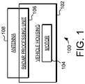
- the unmanned vehicle 100 includes a vehicle housing 102, a motor 104, a radar processing unit 106, and an antenna 108.
- the unmanned vehicle 100 can be any type of unmanned vehicle, including various types of unmanned aerial vehicles and unmanned land vehicles.
- the housing 102 can be any type of suitable housing for the unmanned vehicle 100.
- the motor 104 can be any type of suitable motor that can provide propulsion to the unmanned vehicle 100.
- the housing 102 and motor 104 can include a housing body and motor suitable for a multi-copter.
- the housing 102 and motor 104 can include a housing body and motor suitable for a wheeled delivery drone.
- the unmanned vehicle 100 can include multiple motors 104.
- the unmanned vehicle 100 can include a variety of other features, including batteries, cameras, etc.
- the unmanned vehicle 100 includes the radar processing unit 106 and the antenna 108.
- the antenna 108 includes an antenna body defining at least one transmitting waveguide and at least one receiving waveguide coupled to the radar processing unit 106.
- the radar processing unit 106 transmits and receives radar signals through the transmitting and receiving waveguides.
- the antenna 108 and its included waveguides thus define the field of view for the radar system.
- the antenna body is formed using 3-dimenesional (3D) printing of plastic.
- the antenna body is molded using any suitable molding technique. Both 3D printing and molding can thus be used to define an antenna body with the waveguide structures needed for the desired radar field of view.
- the radar processing unit 106 and antenna 108 can transmit and receive radar signals through the waveguides and use those signals to provide for navigation and obstacle avoidance in the unmanned vehicle 100.
- the antenna body has an exterior shape configured to provide semispherical field of view for radar signals generated by the radar processing unit and transmitted by the antenna body.
- the antenna body has an exterior shape configured to provide full spherical field of view.
- the antenna body can have a semispherical or hemispherical shape exterior shape to provide such a partial or full field of view.
- the antenna body can have a partial or modified polyhedron shape to provide such a partial or full field of view.
- multiple antennas 108 can be used on one unmanned vehicle 100.
- multiple antennas 108 with a semispherical field of view scan can be implemented together on the vehicle 100 and configured to provide a spherical field of view or 360 degree circular field of view around the unmanned vehicle 100.
- a first antenna 108 is positioned on the top side of the housing 102, while a second antenna 108 is positioned on the bottom side of housing 102. Such a configuration can provide a full up and down view for an unmanned aerial vehicle. In another embodiment, a first antenna 108 is positioned on the left side of the housing 102, while a second antenna 108 is positioned on the right side of housing 102. Such a configuration can provide a full or nearly full 360 degree view for an unmanned land vehicle.
- the antenna body is formed together with other elements of the unmanned vehicle 100.
- the antenna body can be formed with or as part of the housing 102.
- the antenna body, including the exterior shape and the transmitting and receiving waveguides can be formed with the same processes used to form the housing 102.
- the housing 102 and the antenna body can be formed together using 3D printing.
- the housing 102 and the antenna body can be formed together using injection molding. In both cases the plastics used to define the exterior shape and the transmitting and receiving waveguides can be defined with the same processes used to define the shapes structures of the unmanned vehicle 100.
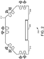
- the radar system 200 includes a radar processing unit 206 and an antenna 208.
- the radar system 200 is exemplary of the type of radar system that can be implemented on an unmanned vehicle, including pilotless aerial vehicles such as multi-copters.
- the antenna 208 includes an antenna body 210 and a metalized surface 212.
- the antenna body 210 defines a plurality of transmitting waveguides and a plurality of receiving waveguides coupled to the radar processing unit 206.
- the transmitting waveguides are coupled to transmitting outputs (TX) and the receiving waveguides are coupled to receiving inputs (RX).
- the configuration of the waveguides and the distribution of the transmitting outputs (TX) and the receiving inputs (RX) determine the define the field of view of the radar system.
- the metalized surface 212 provides the conductivity needed for transmitting electromagnetic waves from the antenna 208.
- the antenna body 210 can be 3D printed from any suitable plastic material.
- the metalized surface 212 of the antenna body 210 can be metalized using suitable metallic materials and any suitable deposition or coating process.
- the antenna body is injection molded.
- the use of a plastic antenna body 210 having a metalized surface 212 and defining transmitting and receiving waveguides can provide the antenna 208 with a very low relative weight. Such a low weight is particularly important in unmanned aerial vehicles such as multi-copters and other types of drones.
- the use of a 3D printed or injection molded plastic antenna body can provide an antenna body with the waveguide structures needed for the desired radar field of view.
- the antenna body 210 has a partial polyhedron shape. This shape allows the different transmitting ports (TX) to transmit the radar signals in different directions. Likewise, the different receiving ports (RX) can receive the reflected radar signals from different directions. Taken together, the partial polyhedron shape can provide semispherical field of view for radar signals generated by the radar processing unit 206 and transmitted out the transmitting ports (TX) and received by the receiving ports (RX).
- the radar processing unit 206 can include any suitable type of radar processing unit. Specifically, the radar processing unit 206 can include one or more packaged integrated circuits configured to generate and receive radar signals. In a typical embodiment the radar processing unit 206 can be configured to include multiple transmission channels and multiple receiver channels, and can thus facilitate multiple-input multiple-output (MIMO) radar operation.
- MIMO multiple-input multiple-output
- the radar processing unit 206 can be implemented to provide a frequency-modulated continuous-wave (FMCW) radar.
- FMCW frequency-modulated continuous-wave
- Such a radar can use an exemplary frequency band of 70-90 GHz and a chirp bandwidth of up to 2GHz. Again, this is just one example and other implementations can also be used.
- the radar processing unit 206 can include a variety of different circuits and devices to facilitate radar operation.
- the radar processing unit 206 can include a variety of filters, analog-to-digital converters (ADCs), monitoring circuits, etc. In most applications it will be desirable to use a radar processing unit 206 with relatively low power requirements.
- ADCs analog-to-digital converters
- the radar processing unit 206 will be implemented as a packaged integrated circuit.
- a packaged integrated circuit can use a variety of package lead technologies, including various types of pins, wire leads and ball grid arrays (BGAs).
- the package leads would provide the input and output interfaces for coupling to other devices on the unmanned vehicle. Additionally, the package leads can provide the interface between the antenna 208 and each of the transmission and receiver channels on the radar processing unit 206.
- the interface between the radar processing unit 206 and the antenna 208 can be realized as a chip-package-waveguide transition.
- the interface between the radar processing unit 206 and the antenna 208 can be realized as a chip-package-PCB-waveguide transition.
- the leads of the packaged radar processing unit 206 are coupled to the transmitting and receiving waveguides of the antenna 208. This connection can be direct, or it can be implemented through intermediate features such as PCB's and other waveguides.
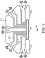
- FIG. 3 a cross-sectional side view of the radar system 200 is illustrated.
- This cross-sectional side view shows the plurality of transmitting waveguides 214 and receiving waveguides 216 that are defined in the antenna body 210.
- Each of the transmitting waveguides 214 and receiving waveguides 216 provides a connection to the corresponding transmitting and receiving I/O on the radar processing unit 206.
- each of the waveguides 214 and 216 can be connected to the radar processing unit 206 through a chip-package-waveguide transition structure.
- the antenna body 210 includes a metalized surface 212.
- the interior walls of the transmitting waveguides 214 and receiving waveguides 216 include the metalized surface 212.
- This metalized surface 212 on the walls of the transmitting waveguides 214 and the receiving waveguides 216 provides the conductivity needed for transmitting electromagnetic waves from the radar processing unit 206 to the transmitting outputs (TX) and from the receiving inputs (RX) to the radar processing unit 206.
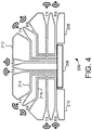
- FIG. 4 a second cross-sectional side view of the radar system 200 is illustrated. Like FIG. 3 , this cross-sectional view shows the plurality of transmitting waveguides 214 and receiving waveguides 216 that are defined in the antenna body 210. However, in this example several of the transmitting waveguides 214 and the receiving waveguides 216 are shared. Specifically, multiple transmitting waveguides 214 are connected to one transmitting output of the radar processing unit 206. Likewise, multiple receiving waveguides 216 are connected to one receiving input of the radar processing unit 206. Thus, in this implementation some of the input and output channels of the radar processing unit 206 are split into multiple antenna outputs and inputs. Such an embodiment can thus be used where the transmitting and receiving channels are limited, or where simply more transmitting ports (TX) and receiving ports (RX) are needed to provide the fully desired field of view for the radar system 200.
- TX transmitting ports
- RX receiving ports
- the radar systems described herein can be applied to a wide variety of unmanned vehicles, including various types of pilotless drones.
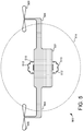
- FIG. 5 a simplified side view of an exemplary unmanned aerial vehicle 500 is illustrated.
- the aerial vehicle 500 includes a vehicle housing 502 and propulsion motors 504.
- the aerial vehicle 500 is a multi-copter type drone device that has multiple propellers 506 driven by the propulsion motors 504.
- the aerial vehicle 500 also includes two radar systems 510.
- Each of the radar systems 510 includes an antenna body 512.
- These antenna bodies 512 each define at least one transmitting waveguide and at least one receiving waveguide. These waveguides are coupled to one or more radar processing units (not shown in FIG. 5 ).
- the radar systems 510 each transmit and receive radar signals through the transmitting and receiving waveguides of the antenna bodies 512.
- the antenna bodies 512 their included waveguides thus define the field of views for the radar systems 510.
- each of the radar systems 510 defines a substantially semispherical field of view. With one antenna body 512 mounted at the top of the vehicle housing 502 and the other antenna body 512 mounted at the bottom of the vehicle housing 502, the two antenna bodies 512 together can provide near full spherical view as represented by the dashed line 514.
- the antenna bodies 512 can be implemented in plastic with a conductive metallic coating, such antenna systems 510 can provided with relatively little weight.
- the radar systems 510 can provide improved vehicle navigation and obstacle detection without excessive weight added to the vehicle 500.
- the antenna bodies 512 are formed separately and attached the vehicle housing 502.
- the antenna bodies 512 can be separately formed and then attached to the vehicle using adhesive or any suitable fastener.
- the antenna bodies 512 are formed together with the vehicle housing 502.
- the antenna bodies 512 including the exterior shape and the transmitting and receiving waveguides can be defined with the same processes used to form the vehicle housing 502.
- the exterior shape waveguides can be implemented as part of the vehicle housing 502.
- the vehicle housing 502 and the antenna bodies 512 can be formed as part of the same 3D printing process.
- the vehicle housing 502 and the antenna bodies 512 can be formed together as part of the same plastic molding process.
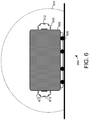
- the land vehicle 600 includes vehicle housing 502 and propulsion motors (not shown in FIG. 6 ).
- the land vehicle 600 is a wheeled device that has multiple wheels 606.
- the land vehicle 600 also includes two radar systems 610.
- Each of the radar systems 610 includes an antenna body 612.
- These antenna bodies 612 each define at least one transmitting waveguide and at least one receiving waveguide. These waveguides are coupled to one or more radar processing units (not shown in FIG. 6 ).
- the radar systems 610 each transmit and receive radar signals through the transmitting and receiving waveguides of the antenna bodies 612.
- the antenna bodies 612 their included waveguides thus define the field of views for the radar systems 610.
- each of the radar systems 610 defines a semispherical field of view. With one antenna body 612 mounted at one side of the vehicle housing 602 and the other antenna body 612 mounted at the opposite side of the vehicle housing 602, the two antenna bodies 612 together can provide near 360 degree view as represented by the dashed line 614.
- the antenna bodies 612 are formed separately and attached the vehicle housing 602. In other embodiments, the antenna bodies 512 are formed together with the vehicle housing 502, using the same processes and materials.
- the antenna bodies 612 can be implemented in plastic, with a conductive coating, such antenna systems 610 can provided with relatively little weight.
- the radar systems 610 can again provide improved vehicle navigation and obstacle detection without excessive weight added to the land vehicle 600.
- the embodiments described herein thus provide radar systems for use on unmanned vehicles.
- the radar systems can be applied to a wide variety of unmanned vehicles, including unmanned aerial vehicles and unmanned land vehicles.
- the unmanned vehicle includes a housing having at least one propulsion motor, a radar processing unit coupled to the body, and an antenna.
- the antenna includes an antenna body defining at least one transmitting waveguide and at least one receiving waveguide coupled to the radar processing unit.
- the antenna body is formed from plastic and includes metalized surface.
- the antenna body is formed from 3-dimensional (3D) plastic printing.
- an unmanned vehicle including: a housing, the housing including at least one propulsion motor; a radar processing unit coupled to the housing; and an antenna, the antenna having an antenna body defining at least one transmitting waveguide and at least one of receiving waveguide, the antenna body formed from plastic and having a metallized surface, the at least one of transmitting waveguide and at least one of receiving waveguide coupled to the radar processing unit.
- an unmanned vehicle including: a housing, the housing including at least one propulsion motor; a radar processing unit coupled to the housing; and an antenna, the antenna including an antenna body defining a plurality of transmitting waveguides and a plurality of receiving waveguides, the antenna body formed from plastic using a 3-dimensional (3D) printing process, the antenna body including a metallized surface, the plurality of transmitting waveguides and plurality of receiving waveguides coupled to the radar processing unit.
- a pilotless aerial drone including: a housing, the housing including at least one propulsion motor; a radar processing unit coupled to the housing; a first antenna coupled to a first surface of the housing, the first antenna including a first antenna body with a first exterior surface shape, the first antenna body defining a first plurality of transmitting waveguides and a first plurality of receiving waveguides, the first antenna body formed from plastic and having a first metallized surface, the first plurality of transmitting waveguides and first plurality of receiving waveguides coupled to the radar processing unit; a second antenna coupled to a second surface of the housing opposite the first surface, the second antenna including a second antenna body with a second exterior surface shape, the second antenna body defining a second plurality of transmitting waveguides and a second plurality of receiving waveguides, the second antenna body formed from plastic and having a second metallized surface, second first plurality of transmitting waveguides and second plurality of receiving waveguides coupled to the radar processing unit; and wherein the first exterior
- the embodiments described herein provide radar systems for use on unmanned vehicles.
- the radar systems can be applied to a wide variety of unmanned vehicles, including unmanned aerial vehicles and unmanned land vehicles.
- the unmanned vehicle comprises a housing having at least one propulsion motor, a radar processing unit coupled to the body, and an antenna.
- the antenna includes an antenna body defining at least one transmitting waveguide and at least one receiving waveguide coupled to the radar processing unit.
- the antenna body is formed from plastic and includes metalized surface.
- the antenna body is formed from 3-dimensional (3D) plastic printing.
- connections may be any type of connection suitable to transfer signals from or to the respective nodes, units or devices, for example via intermediate devices.
- connections may for example be direct connections or indirect connections.
- connections may for example be direct connections or indirect connections.
- other modifications, variations and alternatives are also possible.
- the specifications and drawings are, accordingly, to be regarded in an illustrative rather than in a restrictive sense.
- any reference signs placed between parentheses shall not be construed as limiting the claim.
- the word 'comprising' does not exclude the presence of other elements or steps then those listed in a claim.
- the terms "a” or “an,” as used herein, are defined as one or more than one.
- the use of introductory phrases such as “at least one” and “one or more” in the claims should not be construed to imply that the introduction of another claim element by the indefinite articles “a” or “an” limits any particular claim containing such introduced claim element to inventions containing only one such element, even when the same claim includes the introductory phrases “one or more” or “at least one” and indefinite articles such as “a” or “an.”
Landscapes
- Engineering & Computer Science (AREA)
- Remote Sensing (AREA)
- Radar, Positioning & Navigation (AREA)
- Physics & Mathematics (AREA)
- General Physics & Mathematics (AREA)
- Aviation & Aerospace Engineering (AREA)
- Astronomy & Astrophysics (AREA)
- Computer Security & Cryptography (AREA)
- Electromagnetism (AREA)
- Mechanical Engineering (AREA)
- Transportation (AREA)
- Computer Networks & Wireless Communication (AREA)
- Combustion & Propulsion (AREA)
- Chemical & Material Sciences (AREA)
- Radar Systems Or Details Thereof (AREA)
- Variable-Direction Aerials And Aerial Arrays (AREA)
Abstract
Description
- The embodiments described herein generally relate to unmanned vehicles, and in particular, the use of radar systems for guiding unmanned vehicles.
- Unmanned vehicles are used in a variety of applications. For example, unmanned aerial vehicles (commonly referred to as "drones") are increasingly used in a variety of recreational activities. Unmanned aerial vehicles are also used for a variety of commercial activities, including professional photography, mapping and delivery. Unmanned land vehicles are likewise increasingly used for cleaning, delivery and manufacturing.
- One continuing issue with unmanned vehicles is the need for avoiding obstacles while moving. For example, unmanned aerial drones may need to avoid collisions with other flying objects, and may need to avoid stationary hazards such as trees, buildings and powerlines. Likewise, unmanned land vehicles may need to maneuver around both stationary and moving objects, including people. These unmanned land vehicles may also need to navigate through crowded buildings. In each case there is a need for the unmanned vehicle to locate and avoid potential obstacles while moving.
- Furthermore, in many applications there is a need to provide such functionality without requiring excessive weight or power consumption.
- Aspects of the disclosure are defined in the accompanying claims.
- In a first aspect, there is provided an unmanned vehicle, comprising: a housing, the housing including at least one propulsion motor; a radar processing unit coupled to the housing; and an antenna, the antenna including an antenna body defining at least one transmitting waveguide and at least one of receiving waveguide, the antenna body formed from plastic and having a metallized surface, the at least one of transmitting waveguide and at least one of receiving waveguide coupled to the radar processing unit.
- In one or more embodiments, the antenna body may have an exterior shape configured to provide a semispherical field of view for radar signals generated by the radar processing unit and transmitted by the antenna body.
- In one or more embodiments, the antenna body may have an exterior shape configured to provide a spherical field of view for radar signals generated by the radar processing unit and transmitted by the antenna body.
- In one or more embodiments, the antenna body may have a semispherical exterior shape.
- In one or more embodiments, the antenna body may have a modified polyhedron exterior shape.
- In one or more embodiments, the antenna body may be formed as part of the housing.
- In one or more embodiments, the antenna body may be formed with 3D printing.
- In one or more embodiments, the antenna body may be formed with injection molding.
- In one or more embodiments, the metalized surface may be formed by metallic deposition.
- In one or more embodiments, the unmanned vehicle may further comprise a second antenna, the second antenna having a second antenna body defining at least one second transmitting waveguide and at least one second receiving waveguide, the second antenna body formed from plastic and having a second metallized surface, the at least one second transmitting waveguide and at least one second receiving waveguide coupled to the radar processing unit.
- In one or more embodiments, the antenna body may be coupled to a top side of the housing and the second antenna body may be coupled to a bottom side of the housing.
- In one or more embodiments, the antenna body may be coupled to a first side, wherein the second antenna body may be coupled to a second side opposite the first side.
- In one or more embodiments, the unmanned vehicle may comprise an aerial drone.
- In one or more embodiments, the unmanned vehicle may comprise a wheeled drone.
- In a second aspect, there is provided an unmanned vehicle comprising: a housing, the housing including at least one propulsion motor; a radar processing unit coupled to the housing; and an antenna, the antenna including an antenna body defining a plurality of transmitting waveguides and a plurality of receiving waveguides, the antenna body formed from plastic using a 3-dimensional (3D) printing process, the antenna body including a metallized surface, the plurality of transmitting waveguides and plurality of receiving waveguides coupled to the radar processing unit.
- In one or more embodiments, the antenna body may have a modified polyhedron exterior shape configured to provide semispherical field of view for radar signals generated by the radar processing unit and transmitted by the antenna body.
- In one or more embodiments, the antenna body may have a semispherical exterior shape configured to provide semispherical field of view for radar signals generated by the radar processing unit and transmitted by the antenna body.
- In one or more embodiments, the unmanned vehicle may further comprise a second antenna, the second antenna having a second antenna body defining at least one transmitting waveguide and at least one of receiving waveguide, the second antenna body formed from plastic and having a second metallized surface, the at least one of transmitting waveguide and at least one of receiving waveguide coupled to the radar processing unit.
- In one or more embodiments, the antenna body and the housing may be formed together with the 3D printing process.
- In a third aspect, there is provided a pilotless aerial drone comprising: a housing, the housing including at least one propulsion motor; a radar processing unit coupled to the housing; a first antenna coupled to a first surface of the housing, the first antenna including a first antenna body with a first exterior surface shape, the first antenna body defining a first plurality of transmitting waveguides and a first plurality of receiving waveguides, the first antenna body formed from plastic and having a first metallized surface, the first plurality of transmitting waveguides and first plurality of receiving waveguides coupled to the radar processing unit; a second antenna coupled to a second surface of the housing opposite the first surface, the second antenna including a second antenna body with a second exterior surface shape, the second antenna body defining a second plurality of transmitting waveguides and a second plurality of receiving waveguides, the second antenna body formed from plastic and having a second metallized surface, second first plurality of transmitting waveguides and second plurality of receiving waveguides coupled to the radar processing unit; and wherein the first exterior shape and the second exterior shape are configured to provide a combined spherical field of view for radar signals generated by the radar processing unit and transmitted by the first antenna body and the second antenna body.
-
-
FIG. 1 is a schematic diagram of an unmanned vehicle in accordance with an example embodiment; -
FIG. 2 is a side view of a radar system in accordance with an example embodiment; -
FIG. 3 is a cross-sectional side view of a radar system in accordance with an example embodiment; -
FIG. 4 is a cross-sectional side view of a radar system in accordance with an example embodiment; -
FIG. 5 is a side view of an unmanned aerial vehicle in accordance with an example embodiment; and -
FIG. 6 is a side view of an unmanned aerial vehicle in accordance with an example embodiment. - The embodiments described herein provide radar systems for use on unmanned vehicles. The radar systems can be applied to a wide variety of unmanned vehicles, including unmanned aerial vehicles and unmanned land vehicles. For example, the radar systems can be applied to aerial vehicles commonly referred to as drones or multi-copters. The radar systems can also be applied to a variety of unmanned land vehicles, including ground based recreational or commercial vehicles. For example, the radar systems can be applied to automated delivery or cleaning devices.
- In general, the unmanned vehicle includes a housing having at least one propulsion motor, a radar processing unit coupled to the body, and an antenna. In accordance with the embodiments described herein, the antenna includes an antenna body defining at least one transmitting waveguide and at least one receiving waveguide coupled to the radar processing unit. The antenna body is formed from plastic and includes metalized surface. In one embodiment, the antenna body is formed from 3-dimensional (3D) plastic printing. The metalized coating can then be applied to the surface of the antenna body, including the surfaces of the waveguides.
- Turning now to
FIG.1 , a schematic view of anunmanned vehicle 100 is illustrated. Theunmanned vehicle 100 includes avehicle housing 102, amotor 104, aradar processing unit 106, and anantenna 108. - The
unmanned vehicle 100 can be any type of unmanned vehicle, including various types of unmanned aerial vehicles and unmanned land vehicles. Likewise, thehousing 102 can be any type of suitable housing for theunmanned vehicle 100. Themotor 104 can be any type of suitable motor that can provide propulsion to theunmanned vehicle 100. For example, thehousing 102 andmotor 104 can include a housing body and motor suitable for a multi-copter. In other examples, thehousing 102 andmotor 104 can include a housing body and motor suitable for a wheeled delivery drone. It should be noted that in many applications theunmanned vehicle 100 can includemultiple motors 104. Additionally, theunmanned vehicle 100 can include a variety of other features, including batteries, cameras, etc. - In accordance with the embodiments described herein, the
unmanned vehicle 100 includes theradar processing unit 106 and theantenna 108. In general, theantenna 108 includes an antenna body defining at least one transmitting waveguide and at least one receiving waveguide coupled to theradar processing unit 106. Thus, during operation theradar processing unit 106 transmits and receives radar signals through the transmitting and receiving waveguides. Theantenna 108 and its included waveguides thus define the field of view for the radar system. In one embodiment the antenna body is formed using 3-dimenesional (3D) printing of plastic. In other embodiments the antenna body is molded using any suitable molding technique. Both 3D printing and molding can thus be used to define an antenna body with the waveguide structures needed for the desired radar field of view. When so constructed theradar processing unit 106 andantenna 108 can transmit and receive radar signals through the waveguides and use those signals to provide for navigation and obstacle avoidance in theunmanned vehicle 100. - In one embodiment the antenna body has an exterior shape configured to provide semispherical field of view for radar signals generated by the radar processing unit and transmitted by the antenna body. In another embodiment the antenna body has an exterior shape configured to provide full spherical field of view. For example, the antenna body can have a semispherical or hemispherical shape exterior shape to provide such a partial or full field of view. In other embodiments the antenna body can have a partial or modified polyhedron shape to provide such a partial or full field of view.
- In some applications
multiple antennas 108 can be used on oneunmanned vehicle 100. For example,multiple antennas 108 with a semispherical field of view scan can be implemented together on thevehicle 100 and configured to provide a spherical field of view or 360 degree circular field of view around theunmanned vehicle 100. - In one embodiment, a
first antenna 108 is positioned on the top side of thehousing 102, while asecond antenna 108 is positioned on the bottom side ofhousing 102. Such a configuration can provide a full up and down view for an unmanned aerial vehicle. In another embodiment, afirst antenna 108 is positioned on the left side of thehousing 102, while asecond antenna 108 is positioned on the right side ofhousing 102. Such a configuration can provide a full or nearly full 360 degree view for an unmanned land vehicle. - In one embodiment, the antenna body is formed together with other elements of the
unmanned vehicle 100. For example, the antenna body can be formed with or as part of thehousing 102. In this example, the antenna body, including the exterior shape and the transmitting and receiving waveguides can be formed with the same processes used to form thehousing 102. As one specific example, thehousing 102 and the antenna body can be formed together using 3D printing. As another specific example, thehousing 102 and the antenna body can be formed together using injection molding. In both cases the plastics used to define the exterior shape and the transmitting and receiving waveguides can be defined with the same processes used to define the shapes structures of theunmanned vehicle 100. - Turning now to
FIG. 2 , a side view of anexemplary radar system 200 is illustrated. Theradar system 200 includes aradar processing unit 206 and anantenna 208. Theradar system 200 is exemplary of the type of radar system that can be implemented on an unmanned vehicle, including pilotless aerial vehicles such as multi-copters. - The
antenna 208 includes anantenna body 210 and ametalized surface 212. Theantenna body 210 defines a plurality of transmitting waveguides and a plurality of receiving waveguides coupled to theradar processing unit 206. The transmitting waveguides are coupled to transmitting outputs (TX) and the receiving waveguides are coupled to receiving inputs (RX). The configuration of the waveguides and the distribution of the transmitting outputs (TX) and the receiving inputs (RX) determine the define the field of view of the radar system. The metalizedsurface 212 provides the conductivity needed for transmitting electromagnetic waves from theantenna 208. - Again, the
antenna body 210 can be 3D printed from any suitable plastic material. Likewise, the metalizedsurface 212 of theantenna body 210 can be metalized using suitable metallic materials and any suitable deposition or coating process. In other embodiments the antenna body is injection molded. The use of aplastic antenna body 210 having a metalizedsurface 212 and defining transmitting and receiving waveguides can provide theantenna 208 with a very low relative weight. Such a low weight is particularly important in unmanned aerial vehicles such as multi-copters and other types of drones. - Furthermore, the use of a 3D printed or injection molded plastic antenna body can provide an antenna body with the waveguide structures needed for the desired radar field of view. In the embodiment of
FIG. 2 theantenna body 210 has a partial polyhedron shape. This shape allows the different transmitting ports (TX) to transmit the radar signals in different directions. Likewise, the different receiving ports (RX) can receive the reflected radar signals from different directions. Taken together, the partial polyhedron shape can provide semispherical field of view for radar signals generated by theradar processing unit 206 and transmitted out the transmitting ports (TX) and received by the receiving ports (RX). - The
radar processing unit 206 can include any suitable type of radar processing unit. Specifically, theradar processing unit 206 can include one or more packaged integrated circuits configured to generate and receive radar signals. In a typical embodiment theradar processing unit 206 can be configured to include multiple transmission channels and multiple receiver channels, and can thus facilitate multiple-input multiple-output (MIMO) radar operation. - As one specific example, the
radar processing unit 206 can be implemented to provide a frequency-modulated continuous-wave (FMCW) radar. Such a radar can use an exemplary frequency band of 70-90 GHz and a chirp bandwidth of up to 2GHz. Again, this is just one example and other implementations can also be used. - The
radar processing unit 206 can include a variety of different circuits and devices to facilitate radar operation. For example, theradar processing unit 206 can include a variety of filters, analog-to-digital converters (ADCs), monitoring circuits, etc. In most applications it will be desirable to use aradar processing unit 206 with relatively low power requirements. - In typical embodiment the
radar processing unit 206 will be implemented as a packaged integrated circuit. Such a packaged integrated circuit can use a variety of package lead technologies, including various types of pins, wire leads and ball grid arrays (BGAs). In such an example the package leads would provide the input and output interfaces for coupling to other devices on the unmanned vehicle. Additionally, the package leads can provide the interface between theantenna 208 and each of the transmission and receiver channels on theradar processing unit 206. - As one specific example, the interface between the
radar processing unit 206 and theantenna 208 can be realized as a chip-package-waveguide transition. As another example, the interface between theradar processing unit 206 and theantenna 208 can be realized as a chip-package-PCB-waveguide transition. In each of these examples the leads of the packagedradar processing unit 206 are coupled to the transmitting and receiving waveguides of theantenna 208. This connection can be direct, or it can be implemented through intermediate features such as PCB's and other waveguides. - Turning now to
FIG. 3 , a cross-sectional side view of theradar system 200 is illustrated. This cross-sectional side view shows the plurality of transmittingwaveguides 214 and receivingwaveguides 216 that are defined in theantenna body 210. In this example, there are an equal number of transmittingwaveguides 214 and receivingwaveguides 216. However, that is just one example implementation. - Each of the transmitting
waveguides 214 and receivingwaveguides 216 provides a connection to the corresponding transmitting and receiving I/O on theradar processing unit 206. As one example, each of thewaveguides radar processing unit 206 through a chip-package-waveguide transition structure. - Again, the
antenna body 210 includes a metalizedsurface 212. As can be seen inFIG. 3 , the interior walls of the transmittingwaveguides 214 and receivingwaveguides 216 include the metalizedsurface 212. This metalizedsurface 212 on the walls of the transmittingwaveguides 214 and the receivingwaveguides 216 provides the conductivity needed for transmitting electromagnetic waves from theradar processing unit 206 to the transmitting outputs (TX) and from the receiving inputs (RX) to theradar processing unit 206. - Turning now to
FIG. 4 , a second cross-sectional side view of theradar system 200 is illustrated. LikeFIG. 3 , this cross-sectional view shows the plurality of transmittingwaveguides 214 and receivingwaveguides 216 that are defined in theantenna body 210. However, in this example several of the transmittingwaveguides 214 and the receivingwaveguides 216 are shared. Specifically, multiple transmittingwaveguides 214 are connected to one transmitting output of theradar processing unit 206. Likewise, multiple receivingwaveguides 216 are connected to one receiving input of theradar processing unit 206. Thus, in this implementation some of the input and output channels of theradar processing unit 206 are split into multiple antenna outputs and inputs. Such an embodiment can thus be used where the transmitting and receiving channels are limited, or where simply more transmitting ports (TX) and receiving ports (RX) are needed to provide the fully desired field of view for theradar system 200. - As was described above, the radar systems described herein can be applied to a wide variety of unmanned vehicles, including various types of pilotless drones. Turning now to
FIG. 5 , a simplified side view of an exemplary unmannedaerial vehicle 500 is illustrated. Theaerial vehicle 500 includes avehicle housing 502 andpropulsion motors 504. In this example, theaerial vehicle 500 is a multi-copter type drone device that hasmultiple propellers 506 driven by thepropulsion motors 504. - In accordance with the embodiments described herein, the
aerial vehicle 500 also includes tworadar systems 510. Each of theradar systems 510 includes anantenna body 512. Theseantenna bodies 512 each define at least one transmitting waveguide and at least one receiving waveguide. These waveguides are coupled to one or more radar processing units (not shown inFIG. 5 ). Thus, during operation, theradar systems 510 each transmit and receive radar signals through the transmitting and receiving waveguides of theantenna bodies 512. Theantenna bodies 512 their included waveguides thus define the field of views for theradar systems 510. - In this embodiment each of the
radar systems 510 defines a substantially semispherical field of view. With oneantenna body 512 mounted at the top of thevehicle housing 502 and theother antenna body 512 mounted at the bottom of thevehicle housing 502, the twoantenna bodies 512 together can provide near full spherical view as represented by the dashedline 514. - Again, because the
antenna bodies 512 can be implemented in plastic with a conductive metallic coating,such antenna systems 510 can provided with relatively little weight. Thus, theradar systems 510 can provide improved vehicle navigation and obstacle detection without excessive weight added to thevehicle 500. - In one embodiment, the
antenna bodies 512 are formed separately and attached thevehicle housing 502. For example, theantenna bodies 512 can be separately formed and then attached to the vehicle using adhesive or any suitable fastener. - In other embodiments the
antenna bodies 512 are formed together with thevehicle housing 502. In this example, theantenna bodies 512, including the exterior shape and the transmitting and receiving waveguides can be defined with the same processes used to form thevehicle housing 502. Stated another way, the exterior shape waveguides can be implemented as part of thevehicle housing 502. As one specific example, thevehicle housing 502 and theantenna bodies 512 can be formed as part of the same 3D printing process. As another specific example, thevehicle housing 502 and theantenna bodies 512 can be formed together as part of the same plastic molding process. These embodiments can simplify manufacturing of theunmanned vehicle 500 by not requiring the use of separate procedures and fasteners to affix theantenna bodies 512 to thevehicle housing 502. Furthermore, not requiring adhesives or other fasteners can further reduce the weight of the overallunmanned vehicle 500. - Turning now to
FIG. 6 , a simplified side view of an exemplaryunmanned land vehicle 600 is illustrated. Theland vehicle 600 includesvehicle housing 502 and propulsion motors (not shown inFIG. 6 ). In this example, theland vehicle 600 is a wheeled device that hasmultiple wheels 606. - In accordance with the embodiments described herein, the
land vehicle 600 also includes tworadar systems 610. Each of theradar systems 610 includes anantenna body 612. Theseantenna bodies 612 each define at least one transmitting waveguide and at least one receiving waveguide. These waveguides are coupled to one or more radar processing units (not shown inFIG. 6 ). Thus, during operation, theradar systems 610 each transmit and receive radar signals through the transmitting and receiving waveguides of theantenna bodies 612. Theantenna bodies 612 their included waveguides thus define the field of views for theradar systems 610. - In this embodiment each of the
radar systems 610 defines a semispherical field of view. With oneantenna body 612 mounted at one side of thevehicle housing 602 and theother antenna body 612 mounted at the opposite side of thevehicle housing 602, the twoantenna bodies 612 together can provide near 360 degree view as represented by the dashedline 614. - Again, in one embodiment, the
antenna bodies 612 are formed separately and attached thevehicle housing 602. In other embodiments, theantenna bodies 512 are formed together with thevehicle housing 502, using the same processes and materials. - Again, because the
antenna bodies 612 can be implemented in plastic, with a conductive coating,such antenna systems 610 can provided with relatively little weight. Thus, theradar systems 610 can again provide improved vehicle navigation and obstacle detection without excessive weight added to theland vehicle 600. - The embodiments described herein thus provide radar systems for use on unmanned vehicles. The radar systems can be applied to a wide variety of unmanned vehicles, including unmanned aerial vehicles and unmanned land vehicles. In general, the unmanned vehicle includes a housing having at least one propulsion motor, a radar processing unit coupled to the body, and an antenna. In accordance with the embodiments described herein, the antenna includes an antenna body defining at least one transmitting waveguide and at least one receiving waveguide coupled to the radar processing unit. The antenna body is formed from plastic and includes metalized surface. In one embodiment, the antenna body is formed from 3-dimensional (3D) plastic printing.
- In one embodiment, an unmanned vehicle is provided, including: a housing, the housing including at least one propulsion motor; a radar processing unit coupled to the housing; and an antenna, the antenna having an antenna body defining at least one transmitting waveguide and at least one of receiving waveguide, the antenna body formed from plastic and having a metallized surface, the at least one of transmitting waveguide and at least one of receiving waveguide coupled to the radar processing unit.
- In another embodiment, an unmanned vehicle is provided, including: a housing, the housing including at least one propulsion motor; a radar processing unit coupled to the housing; and an antenna, the antenna including an antenna body defining a plurality of transmitting waveguides and a plurality of receiving waveguides, the antenna body formed from plastic using a 3-dimensional (3D) printing process, the antenna body including a metallized surface, the plurality of transmitting waveguides and plurality of receiving waveguides coupled to the radar processing unit.
- In another embodiment, a pilotless aerial drone is provided, including: a housing, the housing including at least one propulsion motor; a radar processing unit coupled to the housing; a first antenna coupled to a first surface of the housing, the first antenna including a first antenna body with a first exterior surface shape, the first antenna body defining a first plurality of transmitting waveguides and a first plurality of receiving waveguides, the first antenna body formed from plastic and having a first metallized surface, the first plurality of transmitting waveguides and first plurality of receiving waveguides coupled to the radar processing unit; a second antenna coupled to a second surface of the housing opposite the first surface, the second antenna including a second antenna body with a second exterior surface shape, the second antenna body defining a second plurality of transmitting waveguides and a second plurality of receiving waveguides, the second antenna body formed from plastic and having a second metallized surface, second first plurality of transmitting waveguides and second plurality of receiving waveguides coupled to the radar processing unit; and wherein the first exterior shape and the second exterior shape are configured to provide a combined spherical field of view for radar signals generated by the radar processing unit and transmitted by the first antenna body and the second antenna body.
- The embodiments described herein provide radar systems for use on unmanned vehicles. The radar systems can be applied to a wide variety of unmanned vehicles, including unmanned aerial vehicles and unmanned land vehicles. In general, the unmanned vehicle comprises a housing having at least one propulsion motor, a radar processing unit coupled to the body, and an antenna. In accordance with the embodiments described herein, the antenna includes an antenna body defining at least one transmitting waveguide and at least one receiving waveguide coupled to the radar processing unit. The antenna body is formed from plastic and includes metalized surface. In one embodiment, the antenna body is formed from 3-dimensional (3D) plastic printing.
- In the foregoing specification, the invention has been described with reference to specific examples of embodiments of the invention. It will, however, be evident that various modifications and changes may be made therein without departing from the scope of the invention as set forth in the appended claims. For example, the connections may be any type of connection suitable to transfer signals from or to the respective nodes, units or devices, for example via intermediate devices.
- Accordingly, unless implied or stated otherwise the connections may for example be direct connections or indirect connections. However, other modifications, variations and alternatives are also possible. The specifications and drawings are, accordingly, to be regarded in an illustrative rather than in a restrictive sense.
- In the claims, any reference signs placed between parentheses shall not be construed as limiting the claim. The word 'comprising' does not exclude the presence of other elements or steps then those listed in a claim. Furthermore, the terms "a" or "an," as used herein, are defined as one or more than one. Also, the use of introductory phrases such as "at least one" and "one or more" in the claims should not be construed to imply that the introduction of another claim element by the indefinite articles "a" or "an" limits any particular claim containing such introduced claim element to inventions containing only one such element, even when the same claim includes the introductory phrases "one or more" or "at least one" and indefinite articles such as "a" or "an."
- The terms "first," "second," "third," "fourth" and the like in the description and the claims are used for distinguishing between elements and not necessarily for describing a particular structural, sequential or chronological order. It is to be understood that the terms so used are interchangeable under appropriate circumstances. Furthermore, the terms "comprise," "include," "have" and any variations thereof, are intended to cover non-exclusive inclusions, such that a circuit, process, method, article, or apparatus that comprises a list of elements is not necessarily limited to those elements, but may include other elements not expressly listed or inherent to such circuit, process, method, article, or apparatus. The term "coupled," as used herein, is defined as directly or indirectly connected in an electrical or non-electrical manner.
- While the principles of the inventive subject matter have been described above in connection with specific systems, apparatus, and methods, it is to be clearly understood that this description is made only by way of example and not as a limitation on the scope of the inventive subject matter. The various functions or processing blocks discussed herein and illustrated in the Figures may be implemented in hardware, firmware, software or any combination thereof. Further, the phraseology or terminology employed herein is for the purpose of description and not of limitation.
- The foregoing description of specific embodiments reveals the general nature of the inventive subject matter sufficiently that others can, by applying current knowledge, readily modify and/or adapt it for various applications without departing from the general concept. Therefore, such adaptations and modifications are within the meaning and range of equivalents of the disclosed embodiments. The inventive subject matter embraces all such alternatives, modifications, equivalents, and variations as fall within the spirit and broad scope of the appended claims.
Claims (15)
- An unmanned vehicle, comprising:a housing, the housing including at least one propulsion motor;a radar processing unit coupled to the housing; andan antenna, the antenna including an antenna body defining at least one transmitting waveguide and at least one of receiving waveguide, the antenna body formed from plastic and having a metallized surface, the at least one of transmitting waveguide and at least one of receiving waveguide coupled to the radar processing unit.
- The unmanned vehicle of claim 1, wherein the antenna body has an exterior shape configured to provide a semispherical field of view for radar signals generated by the radar processing unit and transmitted by the antenna body.
- The unmanned vehicle of any preceding claim, wherein the antenna body has an exterior shape configured to provide a spherical field of view for radar signals generated by the radar processing unit and transmitted by the antenna body.
- The unmanned vehicle of any preceding claim, wherein the antenna body has a semispherical exterior shape.
- The unmanned vehicle of any preceding claim, wherein the antenna body has a modified polyhedron exterior shape.
- The unmanned vehicle of any preceding claim, wherein the antenna body is formed as part of the housing.
- The unmanned vehicle of any preceding claim, wherein the antenna body is formed with 3D printing.
- The unmanned vehicle of any preceding claim, wherein the antenna body is formed with injection molding.
- The unmanned vehicle of any preceding claim, wherein the metalized surface is formed by metallic deposition.
- The unmanned vehicle of any preceding claim, further comprising a second antenna, the second antenna having a second antenna body defining at least one second transmitting waveguide and at least one second receiving waveguide, the second antenna body formed from plastic and having a second metallized surface, the at least one second transmitting waveguide and at least one second receiving waveguide coupled to the radar processing unit.
- The unmanned vehicle of claim 10, wherein the antenna body is coupled to a top side of the housing and the second antenna body is coupled to a bottom side of the housing.
- The unmanned vehicle of claim 10, wherein the antenna body is coupled to a first side, wherein the second antenna body is coupled to a second side opposite the first side.
- The unmanned vehicle of any preceding claim, wherein the unmanned vehicle comprises an aerial drone.
- The unmanned vehicle of any preceding claim, wherein the unmanned vehicle comprises a wheeled drone.
- A pilotless aerial drone comprising:a housing, the housing including at least one propulsion motor;a radar processing unit coupled to the housing;a first antenna coupled to a first surface of the housing, the first antenna including a first antenna body with a first exterior surface shape, the first antenna body defining a first plurality of transmitting waveguides and a first plurality of receiving waveguides, the first antenna body formed from plastic and having a first metallized surface, the first plurality of transmitting waveguides and first plurality of receiving waveguides coupled to the radar processing unit;a second antenna coupled to a second surface of the housing opposite the first surface, the second antenna including a second antenna body with a second exterior surface shape, the second antenna body defining a second plurality of transmitting waveguides and a second plurality of receiving waveguides, the second antenna body formed from plastic and having a second metallized surface, second first plurality of transmitting waveguides and second plurality of receiving waveguides coupled to the radar processing unit; andwherein the first exterior shape and the second exterior shape are configured to provide a combined spherical field of view for radar signals generated by the radar processing unit and transmitted by the first antenna body and the second antenna body.
Applications Claiming Priority (1)
| Application Number | Priority Date | Filing Date | Title |
|---|---|---|---|
| US15/854,605 US20190198985A1 (en) | 2017-12-26 | 2017-12-26 | Unmanned vehicle radar system |
Publications (2)
| Publication Number | Publication Date |
|---|---|
| EP3506424A1 true EP3506424A1 (en) | 2019-07-03 |
| EP3506424B1 EP3506424B1 (en) | 2024-12-04 |
Family
ID=64650126
Family Applications (1)
| Application Number | Title | Priority Date | Filing Date |
|---|---|---|---|
| EP18210007.3A Active EP3506424B1 (en) | 2017-12-26 | 2018-12-04 | Unmanned vehicle radar system |
Country Status (2)
| Country | Link |
|---|---|
| US (1) | US20190198985A1 (en) |
| EP (1) | EP3506424B1 (en) |
Cited By (1)
| Publication number | Priority date | Publication date | Assignee | Title |
|---|---|---|---|---|
| EP3859891A1 (en) * | 2020-01-31 | 2021-08-04 | Nxp B.V. | Method and apparatus comprising a semiconductor device and test apparatus |
Families Citing this family (7)
| Publication number | Priority date | Publication date | Assignee | Title |
|---|---|---|---|---|
| US11741843B2 (en) * | 2020-04-03 | 2023-08-29 | The Boeing Company | Systems and methods of radar surveillance on-board an autonomous or remotely piloted aircraft |
| US11988740B2 (en) * | 2020-09-08 | 2024-05-21 | Anduril Industries, Inc. | Millimeter wavelength radar antenna for drone interception |
| US11598867B2 (en) | 2020-09-17 | 2023-03-07 | Rockwell Collins, Inc. | Seeker sequential lobing radar antenna system |
| US12074364B2 (en) | 2021-01-21 | 2024-08-27 | The Boeing Company | Sensor waveguide system for a seeker antenna array |
| CN113879521B (en) * | 2021-11-18 | 2023-12-01 | 歌尔科技有限公司 | Unmanned plane |
| EP4489221A1 (en) * | 2023-07-04 | 2025-01-08 | Volkswagen Ag | Antenna and antenna arrangement for a motor vehicle, motor vehicle and method for manufacturing an antenna |
| US20250300365A1 (en) * | 2024-03-25 | 2025-09-25 | Northrop Grumman Systems Corporation | Directional antenna system for noisy environments |
Citations (7)
| Publication number | Priority date | Publication date | Assignee | Title |
|---|---|---|---|---|
| US20040085249A1 (en) * | 2002-11-01 | 2004-05-06 | Nobumasa Kitamori | Sector antenna apparatus and vehicle-mounted transmission and reception apparatus |
| US20090303147A1 (en) * | 2008-06-09 | 2009-12-10 | Intel Corporation | Sectorized, millimeter-wave antenna arrays with optimizable beam coverage for wireless network applications |
| US20100087967A1 (en) * | 2008-10-03 | 2010-04-08 | Honeywell International Inc. | Multi-sector radar sensor |
| US20120084968A1 (en) * | 2010-09-29 | 2012-04-12 | Jayesh Nath | Systems and methods for manufacturing passive waveguide components |
| JP2012167956A (en) * | 2011-02-10 | 2012-09-06 | Hitachi Kokusai Electric Inc | Radar device |
| US9478865B1 (en) * | 2014-12-18 | 2016-10-25 | L-3 Communications Corp. | Configurable horn antenna |
| CN106450782A (en) * | 2016-10-20 | 2017-02-22 | 加特兰微电子科技(上海)有限公司 | End-on-fire antenna and radar assembly |
-
2017
- 2017-12-26 US US15/854,605 patent/US20190198985A1/en not_active Abandoned
-
2018
- 2018-12-04 EP EP18210007.3A patent/EP3506424B1/en active Active
Patent Citations (7)
| Publication number | Priority date | Publication date | Assignee | Title |
|---|---|---|---|---|
| US20040085249A1 (en) * | 2002-11-01 | 2004-05-06 | Nobumasa Kitamori | Sector antenna apparatus and vehicle-mounted transmission and reception apparatus |
| US20090303147A1 (en) * | 2008-06-09 | 2009-12-10 | Intel Corporation | Sectorized, millimeter-wave antenna arrays with optimizable beam coverage for wireless network applications |
| US20100087967A1 (en) * | 2008-10-03 | 2010-04-08 | Honeywell International Inc. | Multi-sector radar sensor |
| US20120084968A1 (en) * | 2010-09-29 | 2012-04-12 | Jayesh Nath | Systems and methods for manufacturing passive waveguide components |
| JP2012167956A (en) * | 2011-02-10 | 2012-09-06 | Hitachi Kokusai Electric Inc | Radar device |
| US9478865B1 (en) * | 2014-12-18 | 2016-10-25 | L-3 Communications Corp. | Configurable horn antenna |
| CN106450782A (en) * | 2016-10-20 | 2017-02-22 | 加特兰微电子科技(上海)有限公司 | End-on-fire antenna and radar assembly |
Cited By (1)
| Publication number | Priority date | Publication date | Assignee | Title |
|---|---|---|---|---|
| EP3859891A1 (en) * | 2020-01-31 | 2021-08-04 | Nxp B.V. | Method and apparatus comprising a semiconductor device and test apparatus |
Also Published As
| Publication number | Publication date |
|---|---|
| US20190198985A1 (en) | 2019-06-27 |
| EP3506424B1 (en) | 2024-12-04 |
Similar Documents
| Publication | Publication Date | Title |
|---|---|---|
| EP3506424B1 (en) | Unmanned vehicle radar system | |
| EP2457305B1 (en) | Method and apparatus for wireless sensing with power harvesting of a wireless signal | |
| US20180145421A1 (en) | Phased Array Antenna Panel with Enhanced Isolation and Reduced Loss | |
| US9960485B2 (en) | Antenna device using EBG structure, wireless communication device, and radar device | |
| WO2012106202A3 (en) | Wireless thermostat adapter system | |
| CN208889845U (en) | A microstrip antenna | |
| CN112701475B (en) | Antenna Arrays, Antennas in Package, Integrated Circuits and Radio Devices | |
| CN109693629A (en) | Millimeter-wave systems grade encapsulation for auxiliary of stopping | |
| US10707564B2 (en) | Unmanned aerial vehicle | |
| CN112534648A (en) | Antenna device, preparation method of antenna device, radar and terminal | |
| CN207895318U (en) | A kind of unmanned plane ad hoc network formation flight control system based on ZigBee | |
| CN104270165B (en) | The integrated system of air traffic CAS and S mode answering machine radio-frequency receiving-transmitting | |
| US10187029B1 (en) | Phase shifter | |
| WO2018094625A1 (en) | Frame of unmanned aerial vehicle, unmanned aerial vehicle and antenna switching method | |
| CN206180088U (en) | Unmanned vehicles's frame and unmanned vehicles | |
| CN109073742A (en) | Radar devices, wireless rotating devices and drones | |
| US20230339609A1 (en) | Autonomous drone component integration | |
| CN112886198B (en) | Antennas, wireless signal processing equipment and drones | |
| CN103887612B (en) | A kind of microwave and millimeter wave Polarization changer | |
| CN104090276A (en) | Radio frequency stealth onboard synthetic aperture radar | |
| CN212517526U (en) | Single-antenna high-isolation linear frequency modulation continuous wave radar antenna system | |
| CN117691332A (en) | Signal transmission device, method and servo system | |
| CN111786106B (en) | Single-antenna high-isolation linear frequency modulation continuous wave radar antenna system | |
| CN220021575U (en) | Three-power divider and millimeter wave radar | |
| CN219534869U (en) | Two power divider and millimeter wave radar |
Legal Events
| Date | Code | Title | Description |
|---|---|---|---|
| PUAI | Public reference made under article 153(3) epc to a published international application that has entered the european phase |
Free format text: ORIGINAL CODE: 0009012 |
|
| STAA | Information on the status of an ep patent application or granted ep patent |
Free format text: STATUS: THE APPLICATION HAS BEEN PUBLISHED |
|
| AK | Designated contracting states |
Kind code of ref document: A1 Designated state(s): AL AT BE BG CH CY CZ DE DK EE ES FI FR GB GR HR HU IE IS IT LI LT LU LV MC MK MT NL NO PL PT RO RS SE SI SK SM TR |
|
| AX | Request for extension of the european patent |
Extension state: BA ME |
|
| STAA | Information on the status of an ep patent application or granted ep patent |
Free format text: STATUS: REQUEST FOR EXAMINATION WAS MADE |
|
| 17P | Request for examination filed |
Effective date: 20200103 |
|
| RBV | Designated contracting states (corrected) |
Designated state(s): AL AT BE BG CH CY CZ DE DK EE ES FI FR GB GR HR HU IE IS IT LI LT LU LV MC MK MT NL NO PL PT RO RS SE SI SK SM TR |
|
| STAA | Information on the status of an ep patent application or granted ep patent |
Free format text: STATUS: EXAMINATION IS IN PROGRESS |
|
| 17Q | First examination report despatched |
Effective date: 20210316 |
|
| GRAP | Despatch of communication of intention to grant a patent |
Free format text: ORIGINAL CODE: EPIDOSNIGR1 |
|
| STAA | Information on the status of an ep patent application or granted ep patent |
Free format text: STATUS: GRANT OF PATENT IS INTENDED |
|
| INTG | Intention to grant announced |
Effective date: 20240517 |
|
| GRAJ | Information related to disapproval of communication of intention to grant by the applicant or resumption of examination proceedings by the epo deleted |
Free format text: ORIGINAL CODE: EPIDOSDIGR1 |
|
| STAA | Information on the status of an ep patent application or granted ep patent |
Free format text: STATUS: EXAMINATION IS IN PROGRESS |
|
| GRAP | Despatch of communication of intention to grant a patent |
Free format text: ORIGINAL CODE: EPIDOSNIGR1 |
|
| STAA | Information on the status of an ep patent application or granted ep patent |
Free format text: STATUS: GRANT OF PATENT IS INTENDED |
|
| INTC | Intention to grant announced (deleted) | ||
| GRAS | Grant fee paid |
Free format text: ORIGINAL CODE: EPIDOSNIGR3 |
|
| GRAA | (expected) grant |
Free format text: ORIGINAL CODE: 0009210 |
|
| STAA | Information on the status of an ep patent application or granted ep patent |
Free format text: STATUS: THE PATENT HAS BEEN GRANTED |
|
| INTG | Intention to grant announced |
Effective date: 20241017 |
|
| AK | Designated contracting states |
Kind code of ref document: B1 Designated state(s): AL AT BE BG CH CY CZ DE DK EE ES FI FR GB GR HR HU IE IS IT LI LT LU LV MC MK MT NL NO PL PT RO RS SE SI SK SM TR |
|
| REG | Reference to a national code |
Ref country code: GB Ref legal event code: FG4D |
|
| REG | Reference to a national code |
Ref country code: CH Ref legal event code: EP |
|
| REG | Reference to a national code |
Ref country code: DE Ref legal event code: R096 Ref document number: 602018077188 Country of ref document: DE |
|
| REG | Reference to a national code |
Ref country code: IE Ref legal event code: FG4D |
|
| REG | Reference to a national code |
Ref country code: LT Ref legal event code: MG9D |
|
| REG | Reference to a national code |
Ref country code: NL Ref legal event code: MP Effective date: 20241204 |
|
| PG25 | Lapsed in a contracting state [announced via postgrant information from national office to epo] |
Ref country code: HR Free format text: LAPSE BECAUSE OF FAILURE TO SUBMIT A TRANSLATION OF THE DESCRIPTION OR TO PAY THE FEE WITHIN THE PRESCRIBED TIME-LIMIT Effective date: 20241204 |
|
| PG25 | Lapsed in a contracting state [announced via postgrant information from national office to epo] |
Ref country code: FI Free format text: LAPSE BECAUSE OF FAILURE TO SUBMIT A TRANSLATION OF THE DESCRIPTION OR TO PAY THE FEE WITHIN THE PRESCRIBED TIME-LIMIT Effective date: 20241204 |
|
| PG25 | Lapsed in a contracting state [announced via postgrant information from national office to epo] |
Ref country code: BG Free format text: LAPSE BECAUSE OF FAILURE TO SUBMIT A TRANSLATION OF THE DESCRIPTION OR TO PAY THE FEE WITHIN THE PRESCRIBED TIME-LIMIT Effective date: 20241204 |
|
| PG25 | Lapsed in a contracting state [announced via postgrant information from national office to epo] |
Ref country code: ES Free format text: LAPSE BECAUSE OF FAILURE TO SUBMIT A TRANSLATION OF THE DESCRIPTION OR TO PAY THE FEE WITHIN THE PRESCRIBED TIME-LIMIT Effective date: 20241204 |
|
| PG25 | Lapsed in a contracting state [announced via postgrant information from national office to epo] |
Ref country code: NO Free format text: LAPSE BECAUSE OF FAILURE TO SUBMIT A TRANSLATION OF THE DESCRIPTION OR TO PAY THE FEE WITHIN THE PRESCRIBED TIME-LIMIT Effective date: 20250304 |
|
| PG25 | Lapsed in a contracting state [announced via postgrant information from national office to epo] |
Ref country code: GR Free format text: LAPSE BECAUSE OF FAILURE TO SUBMIT A TRANSLATION OF THE DESCRIPTION OR TO PAY THE FEE WITHIN THE PRESCRIBED TIME-LIMIT Effective date: 20250305 Ref country code: LV Free format text: LAPSE BECAUSE OF FAILURE TO SUBMIT A TRANSLATION OF THE DESCRIPTION OR TO PAY THE FEE WITHIN THE PRESCRIBED TIME-LIMIT Effective date: 20241204 |
|
| PG25 | Lapsed in a contracting state [announced via postgrant information from national office to epo] |
Ref country code: RS Free format text: LAPSE BECAUSE OF FAILURE TO SUBMIT A TRANSLATION OF THE DESCRIPTION OR TO PAY THE FEE WITHIN THE PRESCRIBED TIME-LIMIT Effective date: 20250304 |
|
| PG25 | Lapsed in a contracting state [announced via postgrant information from national office to epo] |
Ref country code: NL Free format text: LAPSE BECAUSE OF FAILURE TO SUBMIT A TRANSLATION OF THE DESCRIPTION OR TO PAY THE FEE WITHIN THE PRESCRIBED TIME-LIMIT Effective date: 20241204 |
|
| REG | Reference to a national code |
Ref country code: AT Ref legal event code: MK05 Ref document number: 1749171 Country of ref document: AT Kind code of ref document: T Effective date: 20241204 |
|
| PG25 | Lapsed in a contracting state [announced via postgrant information from national office to epo] |
Ref country code: SM Free format text: LAPSE BECAUSE OF FAILURE TO SUBMIT A TRANSLATION OF THE DESCRIPTION OR TO PAY THE FEE WITHIN THE PRESCRIBED TIME-LIMIT Effective date: 20241204 |
|
| PG25 | Lapsed in a contracting state [announced via postgrant information from national office to epo] |
Ref country code: PL Free format text: LAPSE BECAUSE OF FAILURE TO SUBMIT A TRANSLATION OF THE DESCRIPTION OR TO PAY THE FEE WITHIN THE PRESCRIBED TIME-LIMIT Effective date: 20241204 |
|
| PG25 | Lapsed in a contracting state [announced via postgrant information from national office to epo] |
Ref country code: IS Free format text: LAPSE BECAUSE OF FAILURE TO SUBMIT A TRANSLATION OF THE DESCRIPTION OR TO PAY THE FEE WITHIN THE PRESCRIBED TIME-LIMIT Effective date: 20250404 |
|
| PG25 | Lapsed in a contracting state [announced via postgrant information from national office to epo] |
Ref country code: PT Free format text: LAPSE BECAUSE OF FAILURE TO SUBMIT A TRANSLATION OF THE DESCRIPTION OR TO PAY THE FEE WITHIN THE PRESCRIBED TIME-LIMIT Effective date: 20250404 |
|
| PG25 | Lapsed in a contracting state [announced via postgrant information from national office to epo] |
Ref country code: EE Free format text: LAPSE BECAUSE OF FAILURE TO SUBMIT A TRANSLATION OF THE DESCRIPTION OR TO PAY THE FEE WITHIN THE PRESCRIBED TIME-LIMIT Effective date: 20241204 |
|
| PG25 | Lapsed in a contracting state [announced via postgrant information from national office to epo] |
Ref country code: RO Free format text: LAPSE BECAUSE OF FAILURE TO SUBMIT A TRANSLATION OF THE DESCRIPTION OR TO PAY THE FEE WITHIN THE PRESCRIBED TIME-LIMIT Effective date: 20241204 Ref country code: AT Free format text: LAPSE BECAUSE OF FAILURE TO SUBMIT A TRANSLATION OF THE DESCRIPTION OR TO PAY THE FEE WITHIN THE PRESCRIBED TIME-LIMIT Effective date: 20241204 |
|
| PG25 | Lapsed in a contracting state [announced via postgrant information from national office to epo] |
Ref country code: SK Free format text: LAPSE BECAUSE OF FAILURE TO SUBMIT A TRANSLATION OF THE DESCRIPTION OR TO PAY THE FEE WITHIN THE PRESCRIBED TIME-LIMIT Effective date: 20241204 |
|
| PG25 | Lapsed in a contracting state [announced via postgrant information from national office to epo] |
Ref country code: CZ Free format text: LAPSE BECAUSE OF FAILURE TO SUBMIT A TRANSLATION OF THE DESCRIPTION OR TO PAY THE FEE WITHIN THE PRESCRIBED TIME-LIMIT Effective date: 20241204 |
|
| PG25 | Lapsed in a contracting state [announced via postgrant information from national office to epo] |
Ref country code: IT Free format text: LAPSE BECAUSE OF FAILURE TO SUBMIT A TRANSLATION OF THE DESCRIPTION OR TO PAY THE FEE WITHIN THE PRESCRIBED TIME-LIMIT Effective date: 20241204 |
|
| P01 | Opt-out of the competence of the unified patent court (upc) registered |
Free format text: CASE NUMBER: APP_29812/2025 Effective date: 20250623 |
|
| REG | Reference to a national code |
Ref country code: CH Ref legal event code: PL |
|
| PG25 | Lapsed in a contracting state [announced via postgrant information from national office to epo] |
Ref country code: LU Free format text: LAPSE BECAUSE OF NON-PAYMENT OF DUE FEES Effective date: 20241204 |
|
| REG | Reference to a national code |
Ref country code: DE Ref legal event code: R097 Ref document number: 602018077188 Country of ref document: DE |
|
| PG25 | Lapsed in a contracting state [announced via postgrant information from national office to epo] |
Ref country code: SE Free format text: LAPSE BECAUSE OF FAILURE TO SUBMIT A TRANSLATION OF THE DESCRIPTION OR TO PAY THE FEE WITHIN THE PRESCRIBED TIME-LIMIT Effective date: 20241204 |
|
| PG25 | Lapsed in a contracting state [announced via postgrant information from national office to epo] |
Ref country code: MC Free format text: LAPSE BECAUSE OF FAILURE TO SUBMIT A TRANSLATION OF THE DESCRIPTION OR TO PAY THE FEE WITHIN THE PRESCRIBED TIME-LIMIT Effective date: 20241204 |
|
| REG | Reference to a national code |
Ref country code: BE Ref legal event code: MM Effective date: 20241231 |
|
| PG25 | Lapsed in a contracting state [announced via postgrant information from national office to epo] |
Ref country code: DK Free format text: LAPSE BECAUSE OF FAILURE TO SUBMIT A TRANSLATION OF THE DESCRIPTION OR TO PAY THE FEE WITHIN THE PRESCRIBED TIME-LIMIT Effective date: 20241204 |
|
| PLBE | No opposition filed within time limit |
Free format text: ORIGINAL CODE: 0009261 |
|
| STAA | Information on the status of an ep patent application or granted ep patent |
Free format text: STATUS: NO OPPOSITION FILED WITHIN TIME LIMIT |
|
| PG25 | Lapsed in a contracting state [announced via postgrant information from national office to epo] |
Ref country code: BE Free format text: LAPSE BECAUSE OF NON-PAYMENT OF DUE FEES Effective date: 20241231 |
|
| PG25 | Lapsed in a contracting state [announced via postgrant information from national office to epo] |
Ref country code: CH Free format text: LAPSE BECAUSE OF NON-PAYMENT OF DUE FEES Effective date: 20241231 |
|
| PG25 | Lapsed in a contracting state [announced via postgrant information from national office to epo] |
Ref country code: IE Free format text: LAPSE BECAUSE OF NON-PAYMENT OF DUE FEES Effective date: 20241204 |
|
| 26N | No opposition filed |
Effective date: 20250905 |
|
| GBPC | Gb: european patent ceased through non-payment of renewal fee |
Effective date: 20250304 |
|
| PGFP | Annual fee paid to national office [announced via postgrant information from national office to epo] |
Ref country code: DE Payment date: 20251126 Year of fee payment: 8 |
|
| PG25 | Lapsed in a contracting state [announced via postgrant information from national office to epo] |
Ref country code: GB Free format text: LAPSE BECAUSE OF NON-PAYMENT OF DUE FEES Effective date: 20250304 |
|
| PG25 | Lapsed in a contracting state [announced via postgrant information from national office to epo] |
Ref country code: FR Free format text: LAPSE BECAUSE OF NON-PAYMENT OF DUE FEES Effective date: 20250204 |
|
| PG25 | Lapsed in a contracting state [announced via postgrant information from national office to epo] |
Ref country code: CY Free format text: LAPSE BECAUSE OF FAILURE TO SUBMIT A TRANSLATION OF THE DESCRIPTION OR TO PAY THE FEE WITHIN THE PRESCRIBED TIME-LIMIT; INVALID AB INITIO Effective date: 20181204 |