EP3506412A1 - Nonaqueous electrolyte power storage device - Google Patents
Nonaqueous electrolyte power storage device Download PDFInfo
- Publication number
- EP3506412A1 EP3506412A1 EP17846374.1A EP17846374A EP3506412A1 EP 3506412 A1 EP3506412 A1 EP 3506412A1 EP 17846374 A EP17846374 A EP 17846374A EP 3506412 A1 EP3506412 A1 EP 3506412A1
- Authority
- EP
- European Patent Office
- Prior art keywords
- energy storage
- storage device
- nonaqueous electrolyte
- discharge
- graphite
- Prior art date
- Legal status (The legal status is an assumption and is not a legal conclusion. Google has not performed a legal analysis and makes no representation as to the accuracy of the status listed.)
- Granted
Links
Images

Classifications
-
- H—ELECTRICITY
- H01—ELECTRIC ELEMENTS
- H01G—CAPACITORS; CAPACITORS, RECTIFIERS, DETECTORS, SWITCHING DEVICES, LIGHT-SENSITIVE OR TEMPERATURE-SENSITIVE DEVICES OF THE ELECTROLYTIC TYPE
- H01G11/00—Hybrid capacitors, i.e. capacitors having different positive and negative electrodes; Electric double-layer [EDL] capacitors; Processes for the manufacture thereof or of parts thereof
- H01G11/22—Electrodes
- H01G11/30—Electrodes characterised by their material
- H01G11/32—Carbon-based
-
- H—ELECTRICITY
- H01—ELECTRIC ELEMENTS
- H01G—CAPACITORS; CAPACITORS, RECTIFIERS, DETECTORS, SWITCHING DEVICES, LIGHT-SENSITIVE OR TEMPERATURE-SENSITIVE DEVICES OF THE ELECTROLYTIC TYPE
- H01G11/00—Hybrid capacitors, i.e. capacitors having different positive and negative electrodes; Electric double-layer [EDL] capacitors; Processes for the manufacture thereof or of parts thereof
- H01G11/54—Electrolytes
- H01G11/58—Liquid electrolytes
- H01G11/60—Liquid electrolytes characterised by the solvent
-
- H—ELECTRICITY
- H01—ELECTRIC ELEMENTS
- H01M—PROCESSES OR MEANS, e.g. BATTERIES, FOR THE DIRECT CONVERSION OF CHEMICAL ENERGY INTO ELECTRICAL ENERGY
- H01M10/00—Secondary cells; Manufacture thereof
- H01M10/05—Accumulators with non-aqueous electrolyte
- H01M10/052—Li-accumulators
-
- H—ELECTRICITY
- H01—ELECTRIC ELEMENTS
- H01M—PROCESSES OR MEANS, e.g. BATTERIES, FOR THE DIRECT CONVERSION OF CHEMICAL ENERGY INTO ELECTRICAL ENERGY
- H01M10/00—Secondary cells; Manufacture thereof
- H01M10/05—Accumulators with non-aqueous electrolyte
- H01M10/056—Accumulators with non-aqueous electrolyte characterised by the materials used as electrolytes, e.g. mixed inorganic/organic electrolytes
- H01M10/0564—Accumulators with non-aqueous electrolyte characterised by the materials used as electrolytes, e.g. mixed inorganic/organic electrolytes the electrolyte being constituted of organic materials only
- H01M10/0566—Liquid materials
- H01M10/0569—Liquid materials characterised by the solvents
-
- H—ELECTRICITY
- H01—ELECTRIC ELEMENTS
- H01M—PROCESSES OR MEANS, e.g. BATTERIES, FOR THE DIRECT CONVERSION OF CHEMICAL ENERGY INTO ELECTRICAL ENERGY
- H01M4/00—Electrodes
- H01M4/02—Electrodes composed of, or comprising, active material
- H01M4/13—Electrodes for accumulators with non-aqueous electrolyte, e.g. for lithium-accumulators; Processes of manufacture thereof
- H01M4/133—Electrodes based on carbonaceous material, e.g. graphite-intercalation compounds or CFx
-
- H—ELECTRICITY
- H01—ELECTRIC ELEMENTS
- H01M—PROCESSES OR MEANS, e.g. BATTERIES, FOR THE DIRECT CONVERSION OF CHEMICAL ENERGY INTO ELECTRICAL ENERGY
- H01M4/00—Electrodes
- H01M4/02—Electrodes composed of, or comprising, active material
- H01M4/36—Selection of substances as active materials, active masses, active liquids
- H01M4/362—Composites
- H01M4/364—Composites as mixtures
-
- H—ELECTRICITY
- H01—ELECTRIC ELEMENTS
- H01M—PROCESSES OR MEANS, e.g. BATTERIES, FOR THE DIRECT CONVERSION OF CHEMICAL ENERGY INTO ELECTRICAL ENERGY
- H01M4/00—Electrodes
- H01M4/02—Electrodes composed of, or comprising, active material
- H01M4/36—Selection of substances as active materials, active masses, active liquids
- H01M4/58—Selection of substances as active materials, active masses, active liquids of inorganic compounds other than oxides or hydroxides, e.g. sulfides, selenides, tellurides, halogenides or LiCoFy; of polyanionic structures, e.g. phosphates, silicates or borates
- H01M4/583—Carbonaceous material, e.g. graphite-intercalation compounds or CFx
- H01M4/587—Carbonaceous material, e.g. graphite-intercalation compounds or CFx for inserting or intercalating light metals
-
- H—ELECTRICITY
- H01—ELECTRIC ELEMENTS
- H01M—PROCESSES OR MEANS, e.g. BATTERIES, FOR THE DIRECT CONVERSION OF CHEMICAL ENERGY INTO ELECTRICAL ENERGY
- H01M4/00—Electrodes
- H01M4/02—Electrodes composed of, or comprising, active material
- H01M2004/026—Electrodes composed of, or comprising, active material characterised by the polarity
- H01M2004/027—Negative electrodes
-
- H—ELECTRICITY
- H01—ELECTRIC ELEMENTS
- H01M—PROCESSES OR MEANS, e.g. BATTERIES, FOR THE DIRECT CONVERSION OF CHEMICAL ENERGY INTO ELECTRICAL ENERGY
- H01M2300/00—Electrolytes
- H01M2300/0017—Non-aqueous electrolytes
- H01M2300/0025—Organic electrolyte
- H01M2300/0028—Organic electrolyte characterised by the solvent
- H01M2300/0034—Fluorinated solvents
-
- Y—GENERAL TAGGING OF NEW TECHNOLOGICAL DEVELOPMENTS; GENERAL TAGGING OF CROSS-SECTIONAL TECHNOLOGIES SPANNING OVER SEVERAL SECTIONS OF THE IPC; TECHNICAL SUBJECTS COVERED BY FORMER USPC CROSS-REFERENCE ART COLLECTIONS [XRACs] AND DIGESTS
- Y02—TECHNOLOGIES OR APPLICATIONS FOR MITIGATION OR ADAPTATION AGAINST CLIMATE CHANGE
- Y02E—REDUCTION OF GREENHOUSE GAS [GHG] EMISSIONS, RELATED TO ENERGY GENERATION, TRANSMISSION OR DISTRIBUTION
- Y02E60/00—Enabling technologies; Technologies with a potential or indirect contribution to GHG emissions mitigation
- Y02E60/10—Energy storage using batteries
-
- Y—GENERAL TAGGING OF NEW TECHNOLOGICAL DEVELOPMENTS; GENERAL TAGGING OF CROSS-SECTIONAL TECHNOLOGIES SPANNING OVER SEVERAL SECTIONS OF THE IPC; TECHNICAL SUBJECTS COVERED BY FORMER USPC CROSS-REFERENCE ART COLLECTIONS [XRACs] AND DIGESTS
- Y02—TECHNOLOGIES OR APPLICATIONS FOR MITIGATION OR ADAPTATION AGAINST CLIMATE CHANGE
- Y02T—CLIMATE CHANGE MITIGATION TECHNOLOGIES RELATED TO TRANSPORTATION
- Y02T10/00—Road transport of goods or passengers
- Y02T10/60—Other road transportation technologies with climate change mitigation effect
- Y02T10/70—Energy storage systems for electromobility, e.g. batteries
Definitions
- the present invention relates to a nonaqueous electrolyte energy storage device.
- Nonaqueous electrolyte secondary batteries typified by lithium ion secondary batteries have been widely used for electronic devices such as personal computers and communication terminals, automobiles and the like because of their high energy density.
- the nonaqueous electrolyte secondary battery generally has a pair of electrodes electrically isolated by a separator, and a nonaqueous electrolyte interposed between the electrodes, and is configured to perform charge-discharge by delivering ions between both the electrodes.
- capacitors such as lithium ion capacitors and electric double layer capacitors are widely used as nonaqueous electrolyte energy storage devices other than nonaqueous electrolyte secondary batteries.
- nonaqueous electrolyte of such a nonaqueous electrolyte energy storage device various additives and solvents are selected and used in order to improve performance such as enhancement of the capacity.
- a nonaqueous electrolyte contains fluorinated cyclic carbonate such as fluoroethylene carbonate (FEC)
- FEC fluoroethylene carbonate
- nonaqueous electrolyte containing fluorinated cyclic carbonate such as FEC as described above and a negative electrode having graphite are used in combination in a nonaqueous electrolyte energy storage device, there is a disadvantage that the internal resistance increases.
- the nonaqueous electrolyte energy storage device has a high discharge capacity when charged at a relatively high end-of-charge voltage.
- the present invention has been made on the basis of the above circumstances, and an object of the present invention to provide a nonaqueous electrolyte energy storage device which reduces internal resistance while a nonaqueous electrolyte containing fluorinated cyclic carbonate is used and which has a high discharge capacity when charged at a relatively high end-of-charge voltage.
- a nonaqueous electrolyte energy storage device which has been made to solve the above-described problems is a nonaqueous electrolyte energy storage device including: a nonaqueous electrolyte containing a nonaqueous solvent containing fluorinated cyclic carbonate, and an electrolyte salt; and a negative electrode containing graphite and hardly graphitizable carbon.
- the mass of the graphite is larger than the mass of the hardly graphitizable carbon, and the content of the electrolyte salt in the nonaqueous electrolyte is less than 2.0 mol/l.
- nonaqueous electrolyte energy storage device which reduces internal resistance while a nonaqueous electrolyte containing fluorinated cyclic carbonate is used and which has a high discharge capacity when charged at a relatively high end-of-charge voltage.
- a nonaqueous electrolyte energy storage device which has been made to solve the above-described problems is a nonaqueous electrolyte energy storage device (hereinafter, referred to simply as an "energy storage device" including a nonaqueous electrolyte containing a nonaqueous solvent containing fluorinated cyclic carbonate, and an electrolyte salt; and a negative electrode containing graphite and hardly graphitizable carbon.
- the mass of the graphite is larger than the mass of the hardly graphitizable carbon, and the content of the electrolyte salt in the nonaqueous electrolyte is less than 2.0 mol/l.
- the negative electrode contains hardly graphitizable carbon together with graphite as described above, the content (mass) of graphite in the negative electrode is larger than the content (mass) of the hardly graphitizable carbon in the negative electrode, the nonaqueous electrolyte contains a nonaqueous solvent containing fluorinated cyclic carbonate, and an electrolyte salt, and the content of the electrolyte salt in the nonaqueous electrolyte is less than a predetermined content. Accordingly, in the energy storage device, internal resistance can be reduced, and a high discharge capacity can be obtained when the energy storage device is charged at a relatively high end-of-charge voltage.
- graphite gives a charge-discharge curve having a smaller gradient as compared to hardly graphitizable carbon, so that a low potential can be maintained until the end of discharge.
- a high closed circuit voltage can be maintained in a wide range of depth of discharge (DOD), so that a high energy density can be obtained.
- the "discharge” of the negative electrode means that ions such as lithium ions are electrochemically desorbed or detached from graphite and hardly graphitizable carbon
- the "charge” of the negative electrode means that ions such as lithium ions are electrochemically inserted into or adsorbed to graphite and hardly graphitizable carbon.
- the "graphite” refers to a carbon material in which the average grid spacing (d002) of the (002) surface as determined by a wide angle X-ray diffraction method is less than 0.340 nm.
- the average grid spacing (d002) of graphite is preferably 0.338 nm or less.
- the "hardly graphitizable carbon” refers to a carbon material having an average grid spacing (d002) of 0.340 nm or more.
- the average grid spacing (d002) of hardly graphitizable carbon is preferably 0.370 nm or more.
- the mass ratio of the graphite to the hardly graphitizable carbon is preferably 70/30 or more and 96/4 or less.
- the mass ratio of graphite and hardly graphitizable carbon is within the above-mentioned range, the internal resistance of the energy storage device can be further reduced, and a higher discharge capacity can be obtained when the energy storage device is charged at a relatively high end-of-charge voltage.
- the negative electrode contains the graphite and the hardly graphitizable carbon as a negative active material, and the total content ratio of the graphite and the hardly graphitizable carbon is 90% by mass or more based on the amount of the negative active material.
- the effects of the energy storage device i.e. reduction of internal resistance and enhancement of the capacity, can be further exhibited.
- the content of fluorinated cyclic carbonate in the nonaqueous solvent is preferably 5% by volume or more and 25% by volume or less.
- the effects of the energy storage device i.e. reduction of internal resistance and enhancement of the capacity, can be further exhibited.
- the negative electrode contains graphite particles and hardly graphitizable carbon particles.
- graphite particles and hardly graphitizable carbon particles are present separately, the effects of the energy storage device, i.e. reduction of internal resistance and enhancement of the capacity, can be further exhibited.
- the positive electrode potential at an end-of-charge voltage in normal use is preferably 4.40 V (vs. Li/Li + ) or more.
- the energy storage device can be suitably used as an energy storage device having a positive electrode potential of 4.40 V (vs. Li/Li + ) or more at an end-of-charge voltage in normal use.
- the term "in normal use” is a case where the energy storage device is used while charge conditions recommended or specified in the energy storage device are employed, or a case where the energy storage device is used by applying a charger for the energy storage device when the charger is prepared.
- the end-of-charge voltage in normal use is preferably 4.35 V or more.
- a high discharge capacity can be effectively obtained when the energy storage device is charged at a relatively high end-of-charge voltage. Therefore, the energy storage device can be suitably used as an energy storage device having an end-of-charge voltage of 4.35 V or more in normal use.
- V0 is an end-of-charge voltage in normal use
- V1 is an end-of-discharge voltage
- A is a depth of discharge (%) when the energy storage device is discharged to a closed circuit voltage (V0 + V1)/2 in constant current discharge at a discharge rate 1C.
- the depth of discharge as used herein refers to a ratio obtained by dividing a discharge capacity at the time of discharging the energy storage device in constant current discharge at a discharge rate 1C from an end-of-charge voltage V0 to a predetermined voltage in normal use by a discharge capacity at the time of discharging the energy storage device in constant current discharge at a discharge rate 1C from an end-of-charge voltage V0 to an end-of-discharge voltage V1.
- Graphite and hardly graphitizable carbon are different in gradient of a charge-discharge curve, graphite has a higher charge-discharge capacity in a lower potential range, and hardly graphitizable carbon has a higher charge-discharge capacity in a higher potential range.
- graphite when a negative electrode in which graphite and hardly graphitizable carbon are mixed is used, graphite is primarily discharged at the initial stage of discharge in which the negative electrode potential is low, and when discharge progresses and the negative electrode potential is high, discharge of hardly graphitizable carbon primarily occurs.
- graphite can maintain a lower potential until the end of discharge as compared to hardly graphitizable carbon.
- the above formula (1) is derived from a discharge curve of the energy storage device. That is, when the energy storage device includes a negative electrode in which the mass ratio of graphite and hardly graphitizable carbon is within a preferred range where the ratio of graphite is higher, the energy storage device satisfies the above formula (1). Thus, when the energy storage device satisfies the above formula (1), the effects of the energy storage device, i.e. reduction of internal resistance and enhancement of the capacity, are further suitably exhibited.
- V0 - V is an end-of-charge voltage in normal use
- V1 is an end-of-discharge voltage
- V is a closed circuit voltage at the time when the energy storage device is discharged to a depth of discharge of 90% at a discharge rate 1C.
- the above formula (2) is derived from a discharge curve of the energy storage device on the basis of a difference in gradient of the charge-discharge curve between graphite and hardly graphitizable carbon. That is, when the energy storage device includes a negative electrode in which the mass ratio of graphite and hardly graphitizable carbon is within a preferred range where the ratio of graphite is higher, the energy storage device satisfies the above formula (2). Thus, when the energy storage device satisfies the above formula (2), the effects of the energy storage device, i.e. reduction of internal resistance and enhancement of the capacity, are further suitably exhibited.
- the ratio of a discharge capacity in a potential range of 0.02 V (vs. Li/Li + ) to 0.2 V (vs. Li/Li + ) to a discharge capacity in a potential range of 0.02 V (vs. Li/Li + ) to 2.0 V (vs. Li/Li + ) in the negative electrode is preferably 70% or more.
- the ratio of the discharge capacity in the negative electrode is also based on a difference in gradient of the charge-discharge curve between graphite and hardly graphitizable carbon.
- the ratio of the discharge capacity in the negative electrode of the energy storage device is 70% or more.
- An energy storage device includes a positive electrode, a negative electrode, and a nonaqueous electrolyte.
- a nonaqueous electrolyte secondary battery will be described as one example of the energy storage device.
- the positive electrode and the negative electrode form electrode assemblies stacked alternately by laminating or winding the positive electrode and the negative electrode with a separator interposed therebetween.
- the electrode assembly is placed in a battery case, and the nonaqueous electrolyte fills the battery case.
- the nonaqueous electrolyte is interposed between the positive electrode and the negative electrode.
- the battery case a well-known metal battery case, resin battery case or the like which is normally used as a battery case for a nonaqueous electrolyte secondary battery can be used.
- the positive electrode includes a positive electrode substrate, or a positive active material layer disposed on the positive electrode substrate directly or with an intermediate layer interposed therebetween.
- the positive electrode substrate has conductivity.
- a metal such as aluminum, titanium, tantalum or stainless steel or an alloy thereof is used.
- aluminum and an aluminum alloy are preferable from the viewpoint of balance of potential resistance, the level of conductivity and cost.
- examples of the form of the positive electrode substrate include foils and vapor deposition films, with foils being preferable from the viewpoint of cost. That is, an aluminum foil is preferable as the positive electrode substrate.
- Examples of the aluminum or aluminum alloy may include A1085P and A3003P specified in JIS-H-4000 (2014).
- the intermediate layer is a layer covering a surface of the positive electrode substrate, and contains conductive particles such as carbon particles, so that contact resistance between the positive electrode substrate and the positive active material layer is reduced.
- the configuration of the intermediate layer is not particularly limited, and can be formed from, for example, a composition containing a resin binder and conductive particles.
- the term "having conductivity” means that the volume resistivity measured in accordance with JIS-H-0505 (1975) is 10 7 ⁇ ⁇ cm or less, and the term “non-conductive” means that the volume resistivity is more than 10 7 ⁇ ⁇ cm.
- the positive active material layer is formed of a so-called positive electrode mixture containing a positive active material.
- the positive electrode mixture that forms the positive active material layer contains optional components such as a conductive agent, a binder (binding agent), a thickener, and a filler as necessary.
- Examples of the positive active material include composite oxides represented by Li x MO y (M represents at least one transition metal) (Li x CoO 2 , Li x NiO 2 , Li x MnO 3 , Li x Ni ⁇ Co (1- ⁇ ) O 2 , Li x Ni ⁇ Mn ⁇ CO (1- ⁇ - ⁇ ) O 2 and the like each having a layered ⁇ -NaFeO 2 -type crystal structure; Li x Mn 2 O 4 ,Li x Ni ⁇ Mn (2- ⁇ ) O 4 and the like having a spinel-type crystal structure), and polyanion compounds represented by Li w Me x (XO y ) z (Me represents at least one transition metal, and X is, for example, P, Si, B or V) (LiFePO 4 , LiMnPO 4 , LiNiPO 4 , LiCoPO 4 , Li 3 V 2 (PO 4 ) 3 , Li 2 MnSiO 4 , Li 2 CoPO 4
- the conductive agent is not particularly limited as long as it is a conductive material that does not adversely affect battery performance.
- Examples of the conductive agent include natural or artificial graphite; carbon black such as furnace black, acetylene black and ketjen black; metals; and conductive ceramics.
- Examples of the shape of the conductive agent include powder shapes and fibrous shapes.
- binder examples include thermoplastic resins such as fluororesins (polytetrafluoroethylene (PTFE), polyvinylidene fluoride (PVDF), polyethylene, polypropylene and polyimide; elastomers such as ethylene propylene diene rubber (EPDM), sulfonated EPDM, styrene butadiene rubber (SBR) and fluorine rubber; and polysaccharide polymers.
- PTFE polytetrafluoroethylene
- PVDF polyvinylidene fluoride
- EPDM ethylene propylene diene rubber
- SBR styrene butadiene rubber
- fluorine rubber examples include polysaccharide polymers.
- the thickener examples include polysaccharide polymers such as carboxymethylcellulose (CMC) and methylcellulose.
- CMC carboxymethylcellulose
- methylcellulose a functional group reactive with lithium
- the filler is not particularly limited as long as it does not adversely affect battery performance.
- the main component of the filler include polyolefins such as polypropylene and polyethylene, silica, alumina, zeolite, glass and carbon.
- the negative electrode includes a negative electrode substrate, or a negative active material layer disposed on the negative electrode substrate directly or with an intermediate layer interposed therebetween.
- the intermediate layer may have the same configuration as that of the intermediate layer for the positive electrode.
- the negative electrode substrate may have the same configuration as that of the positive electrode substrate, but as a material, a metal such as copper, nickel, stainless steel or nickel-plated steel or an alloy thereof is used, and copper or a copper alloy is preferable. That is, a copper foil is preferable as the negative electrode substrate. Examples of the copper foil include rolled copper foils and electrolytic copper foils.
- the negative active material layer is formed of a so-called negative electrode mixture containing a negative active material.
- the negative electrode mixture that forms the negative active material layer contains optional components such as a conductive agent, a binder (binding agent), a thickener, and a filler as necessary.
- a conductive agent such as a conductive agent, a binder (binding agent), a thickener and a filler
- the same components as in the positive active material layer can be used.
- the negative active material layer contains graphite and hardly graphitizable carbon as a negative active material.
- the mass ratio of graphite to hardly graphitizable carbon (graphite/hardly graphitizable carbon) in the negative electrode (negative active material layer) is not particularly limited as long as the ratio of graphite is higher than the ratio of hardly graphitizable carbon, and the mass ratio of graphite to hardly graphitizable carbon may be 60/40 or more, but is preferably 70/30 or more, more preferably 80/20 or more, still more preferably 85/15 or more.
- the mass ratio of graphite to hardly graphitizable carbon is preferably 96/4 or less, more preferably 90/10 or less.
- the mass ratio of graphite and hardly graphitizable carbon is within the above-mentioned range, the internal resistance of the energy storage device can be further reduced, and a higher discharge capacity can be obtained when the energy storage device is charged at a relatively high end-of-charge voltage.
- the negative active material layer contains graphite particles and hardly graphitizable carbon particles as a negative active material.
- graphite particles and hardly graphitizable carbon particles are present as separate particles in the negative active material layer, the effects of the energy storage device, i.e. reduction of internal resistance and enhancement of the capacity, can be more suitably exhibited.
- the negative active material may further contain a negative active material other than graphite and hardly graphitizable carbon.
- a negative active material other than graphite and hardly graphitizable carbon.
- a known material capable of absorbing and desorbing lithium ions is normally used, and specific examples include metals or semimetals such as Si and Sn; metal oxides or semimetal oxides such as Si oxides and Sn oxides; polyphosphoric acid compounds; and carbon materials other than graphite and hardly graphitizable carbon (easily graphitizable carbon etc.).
- the lower limit of the total content ratio of the graphite and the hardly graphitizable carbon is preferably 90% by mass, more preferably 95% by mass, still more preferably 99% by mass based on the amount of the negative active material.
- the lower limit of the content of graphite in the entire negative active material layer is preferably 60% by mass, more preferably 70% by mass, still more preferably 80% by mass, especially preferably 85% by mass.
- the upper limit of the content ratio is preferably 96% by mass, more preferably 95% by mass, still more preferably 90% by mass.
- the lower limit of the content of hardly graphitizable carbon in the entire negative active material layer is preferably 4% by mass, more preferably 5% by mass, still more preferably 10% by mass.
- the upper limit of the content ratio is preferably 40% by mass, more preferably 30% by mass, still more preferably 20% by mass, especially preferably 15% by mass.
- the content ratio of graphite in the entire negative active material layer is the total content ratio of graphite including graphite as a negative active material and graphite as a conductive agent etc. This also applies to hardly graphitizable carbon.
- the negative active material layer may contain a typical nonmetallic element such as B, N, P, F, Cl, Br or I, a typical metal element such as Li, Na, Mg, Al, K, Ca, Zn, Ga or Ge, or a transition metal element such as Sc, Ti, V, Cr, Mn, Fe, Co, Ni, Cu, Mo, Zr, Ta, Hf, Nb or W.
- a typical nonmetallic element such as B, N, P, F, Cl, Br or I
- a typical metal element such as Li, Na, Mg, Al, K, Ca, Zn, Ga or Ge
- a transition metal element such as Sc, Ti, V, Cr, Mn, Fe, Co, Ni, Cu, Mo, Zr, Ta, Hf, Nb or W.
- a material of the separator for example, a woven fabric, a nonwoven fabric, a porous resin film or the like is used.
- a porous resin film is preferable from the viewpoint of strength
- a nonwoven fabric is preferable from the viewpoint of liquid retainability of the nonaqueous electrolyte.
- a polyolefin such as polyethylene or polypropylene is preferable from the viewpoint of strength
- a polyimide, an aramid or the like is preferable from the viewpoint of oxidative decomposition resistance. Further, these resins may be combined.
- the nonaqueous electrolyte is formed by dissolving an electrolyte salt in a nonaqueous solvent, and includes fluorinated cyclic carbonate as the nonaqueous solvent.
- nonaqueous solvent contains fluorinated cyclic carbonate, it is possible to suppress side reactions (e.g. oxidative decomposition of nonaqueous solvent etc.) that may occur during charge-discharge of the nonaqueous electrolyte energy storage device, leading to improvement charge-discharge cycle performance.
- fluorinated cyclic carbonate examples include fluoroethylene carbonate (FEC), difluoroethylene carbonate, trifluoropropylene carbonate and the like can be mentioned, and FEC is preferable.
- FEC fluoroethylene carbonate
- difluoroethylene carbonate difluoroethylene carbonate
- trifluoropropylene carbonate trifluoropropylene carbonate
- the fluorinated cyclic carbonates may be used singly, or in combination of two or more thereof.
- the content of the fluorinated cyclic carbonate is not particularly limited, but the lower limit of the content is preferably 2% by volume, more preferably 5% by volume, still more preferably 10% by volume based on the total amount of the nonaqueous solvent.
- the upper limit of the content is preferably 50% by volume, more preferably 30% by volume, still more preferably 25% by volume, even more preferably 20% by volume.
- the content of the fluorinated cyclic carbonate based on the amount of the nonaqueous solvent is preferably 2% by volume or more and 50% by volume or less, more preferably 5% by volume or more and 30% by volume or less, more preferably 5% by volume or more and 25% by volume or less, still more preferably 10% by volume or more and 20% by volume or less.
- the content of the fluorinated cyclic carbonate is not less than the lower limit, it is possible to effectively improve the charge-discharge cycle performance of the energy storage device using the nonaqueous electrolyte.
- the content of the fluorinated cyclic carbonate is not more than the upper limit, it is possible to suppress an increase in internal resistance of the energy storage device using the nonaqueous electrolyte. That is, when the content of the fluorinated cyclic carbonate is within the above-mentioned range, it is possible to effectively improve the charge-discharge cycle performance of the energy storage device using the nonaqueous electrolyte, and it is possible to suppress an increase in internal resistance.
- nonaqueous solvent other than fluorinated cyclic carbonate a known nonaqueous solvent that is normally used as a nonaqueous solvent of a general nonaqueous electrolyte for an energy storage device can be used.
- the nonaqueous solvent include cyclic carbonate, chain carbonate, ester, ether, amide, sulfone, lactone and nitrile. Among them, it is preferable to use at least cyclic carbonate or chain carbonate, and it is more preferable to use chain carbonate.
- the ratio of the total volume of the fluorinated cyclic carbonate and other cyclic carbonate to the volume of chain carbonate is not particularly limited, but for example, it is preferably 5/95 or more and 50/50 or less.
- cyclic carbonate may include ethylene carbonate (EC), propylene carbonate (PC), butylene carbonate (BC), vinylene carbonate (VC), vinylethylene carbonate (VEC), chloroethylene carbonate, styrene carbonate, catechol carbonate, 1-phenylvinylene carbonate and 1,2-diphenylvinylene carbonate, and among them, EC is preferable.
- chain carbonate may include diethyl carbonate (DEC), dimethyl carbonate (DMC), ethyl methyl carbonate (EMC) and diphenyl carbonate, and among them, EMC is preferable.
- DEC diethyl carbonate
- DMC dimethyl carbonate
- EMC ethyl methyl carbonate
- diphenyl carbonate diphenyl carbonate
- the electrolyte salt a known electrolyte salt that is normally used as a general electrolyte salt of a nonaqueous electrolyte for an energy storage device can be used.
- the electrolyte salt may include lithium salts, sodium salts, potassium salts, magnesium salts, and onium salts, and lithium salts are preferable.
- lithium salt may include inorganic lithium salts such as LiPF 6 , LiPO 2 F 2 , LiBF 4 , LiClO 4 and LiN(SO 2 F) 2 , and lithium salts having a fluorohydrocarbon group, such as LiSO 3 CF 3 , LiN(SO 2 CF 3 ) 2 , LiN(SO 2 C 2 F 5 ) 2 , LiN(SO 2 CF 3 )(SO 2 C 4 F 9 ), LiC(SO 2 CF 3 ) 3 and LiC(SO 2 C 2 F 5 ) 3 .
- inorganic lithium salts are preferable, and LiPF 6 is more preferable.
- the lower limit of the content of the electrolyte salt in the nonaqueous electrolyte is preferably 0.1 mol/l, more preferably 0.3 mol/l, still more preferably 0.5 mol/l, especially preferably 0.7 mol/l.
- the upper limit of the content of the electrolyte salt in the nonaqueous electrolyte is less than 2.0 mol/l, preferably 1.8 mol/l, more preferably 1.6 mol/l, still more preferably 1.5 mol/l.
- the nonaqueous electrolyte may contain components other than the electrolyte salt and the nonaqueous solvent as long as the effect of the present invention is not impaired.
- the other components may include various additives that are contained in a general nonaqueous electrolyte for an energy storage device.
- the content of the other components in the nonaqueous electrolyte may be preferably 5% by mass or less, more preferably 3% by mass or less.
- Examples of the other components may include sultones (cyclic sulfonic acid esters) such as 1,3-propene sultone, 1,4-butene sultone, 1,3-propane sultone, 1,4-butane sultone and 2,4-butane sultone.
- sultones cyclic sulfonic acid esters
- unsaturated sultones are preferable, and 1,3-propene sultone is more preferable.
- the lower limit of the content of sultone in the nonaqueous electrolyte is not particularly limited, and is, for example, 0.1% by mass, preferably 1% by mass.
- the upper limit of the content of the sultone is, for example, 5% by mass, preferably 3% by mass.
- the end-of-charge voltage at the time of normal use of the energy storage device is not particularly limited, and may be, for example, 4.0 V or 4.2 V or more, but is preferably 4.35 V or more.
- the upper limit of the end-of-charge voltage is, for example, 5.0 V, preferably 4.8 V, more preferably 4.5 V.
- the positive electrode potential at an end-of-charge voltage at the time of normal use of the energy storage device is not particularly limited, and may be, for example, 4.10 V (vs. Li/Li + ) or 4.30 V (vs. Li/Li + ) or more, but is preferably 4.40 V (vs. Li/Li + ) or more, more preferably 4.45 V (vs. Li/Li + ).
- the upper limit of the positive electrode potential at an end-of-charge voltage is, for example, 5.10 V (vs. Li/Li + ), preferably 4.90 V (vs. Li/Li + ), more preferably 4.60 V (vs. Li/Li + ).
- V0 - V1 ⁇ A/100 > 1...(1), where V0 is an end-of-charge voltage in normal use, V1 is an end-of-discharge voltage, and A is a depth of discharge (%) when the energy storage device is discharged to a closed circuit voltage (V0 + V1)/2 in constant current discharge at a discharge rate 1C.
- the end-of-charge voltage V0 is as described above.
- the end-of-discharge voltage V1 is not particularly limited, and for example, the lower limit may be 2.5 V, or may be 2.75 V.
- the upper limit of V1 may be 3.0 V, or may be 2.9 V.
- the lower limit of the value on the left side of the above formula (1) is more preferably 1.02, still more preferably 1.04.
- the upper limit of this value is, for example, 1.2, and may be 1.1, or may be 1.05.
- V0 - V is an end-of-charge voltage in normal use
- V1 is an end-of-discharge voltage
- V is a closed circuit voltage at the time when the energy storage device is discharged to a depth of discharge of 90% at a discharge rate 1C.
- the lower limit of the value on the left side of the above formula (2) is, for example, 0.5, and may be 0.55, or may be 0.6.
- the lower limit of the ratio of a discharge capacity in a potential range of 0.02 V (vs. Li/Li + ) to 0.2 V (vs. Li/Li + ) to a discharge capacity in a potential range of 0.02 V (vs. Li/Li + ) to 2.0 V (vs. Li/Li + ) in the negative electrode is preferably 70%, more preferably 72%.
- the upper limit of the ratio is not particularly limited, and may be, for example, 80%, preferably 76%, more preferably 75%.
- the ratio of a discharge capacity in a potential range of 0.02 V (vs. Li/Li + ) to 0.2 V (vs. Li/Li + ) to a discharge capacity in a potential range of 0.02 V (vs. Li/Li + ) to 2.0 V (vs. Li/Li + ) in the negative electrode is determined in the following manner. First, a negative electrode is prepared.
- the negative electrode to be prepared may be obtained by providing a negative active material layer containing a negative active material and a conductive agent, a binder or the like as necessary on a conductive negative electrode substrate, or obtained by unsealing a case of a nonaqueous electrolyte energy storage device in an atmosphere at a dew point of -50°C or lower, taking out an electrode assembly from the case, and removing a stacked positive electrode and separator.
- a nonaqueous electrolyte energy storage device having the negative electrode and metal lithium as a counter electrode is prepared.
- nonaqueous electrolyte a nonaqueous electrolyte obtained by mixing EMC (ethylmethyl carbonate) and FEC (fluoroethylene carbonate) at a volume ratio of 90 : 10, and adding LiPF 6 as an electrolyte salt at a concentration of 1.0 mol/l is used.
- EMC ethylmethyl carbonate
- FEC fluoroethylene carbonate
- LiPF 6 an electrolyte salt at a concentration of 1.0 mol/l
- a constant current discharge (lithium desorption) is performed at a discharge rate of 0.1C and an end-of-charge potential of 2.0V (vs. Li/Li + ), a quiescent period of 10 minutes is then provided.
- the charge-discharge are carried out by two cycles, and the ratio of a discharge capacity in a potential range of 0.02 V to 0.2 V (vs. Li/Li + ) to a discharge capacity in a potential range of 0.02 V(vs. Li/Li + ) to 2.0 V (vs. Li/Li + ) at the second cycle is the ratio of a discharge capacity in a potential range of 0.02 V (vs. Li/Li + ) to 0.2 V (vs. Li/Li + ) to a discharge capacity in a potential range of 0.02 V (vs. Li/Li + ) to 2.0 V (vs. Li/Li + ) in the negative electrode.
- the method for producing the energy storage device is not particularly limited, and known methods can be combined.
- the production method includes, for example, steps of: preparing a positive electrode and a negative electrode; preparing a nonaqueous electrolyte; forming alternately stacked electrode assemblies by laminating or winding the positive electrode and the negative electrode with a separator interposed therebetween; placing the positive electrode and the negative electrode in a battery case; and injecting the nonaqueous electrolyte in the battery case.
- the injection can be performed by a known method. After the injection, a nonaqueous electrolyte secondary battery (nonaqueous electrolyte energy storage device) can be obtained by sealing the injection port.
- the present invention is not limited to the above-described embodiment, but may be carried out in modes in which various changes and modifications are made in addition to the above-described modes.
- the mode in which the nonaqueous electrolyte energy storage device is a nonaqueous electrolyte secondary battery has been mainly described, but the nonaqueous electrolyte energy storage device may be other nonaqueous electrolyte energy storage device.
- the other nonaqueous electrolyte energy storage device include capacitors (electric double layer capacitors and lithium ion capacitors).
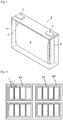
- Fig. 1 shows a schematic view of a rectangular nonaqueous electrolyte secondary battery 1 as one embodiment of a nonaqueous electrolyte energy storage device according to the present invention.
- Fig. 1 is a view showing the inside of a battery case in a perspective manner.
- an electrode assembly 2 is contained in a battery case 3.
- the electrode assembly 2 is formed by winding a positive electrode and a negative electrode with a separator interposed between the positive electrode and the negative electrode, the positive electrode including a positive active material, the negative electrode including a negative active material.
- the positive electrode is electrically connected to a positive electrode terminal 4 through a positive electrode lead 4' and the negative electrode is electrically connected to a negative electrode terminal 5 through a negative electrode lead 5'.
- the configuration of the nonaqueous electrolyte energy storage device according to the present invention is not particularly limited, and examples thereof include cylindrical energy storage devices, prismatic energy storage devices (rectangular energy storage devices) and flat energy storage devices.
- the present invention can also be implemented as an energy storage apparatus including a plurality of nonaqueous electrolyte energy storage devices described above.
- Fig. 2 shows one embodiment of an energy storage apparatus.
- an energy storage apparatus 30 includes a plurality of energy storage units 20.
- Each of the energy storage units 20 includes a plurality of nonaqueous electrolyte energy storage devices 1.
- the energy storage apparatus 30 can be mounted as a power source for an automobile such as an electric vehicle (EV), a hybrid vehicle (HEV), a plug-in hybrid vehicle (PHEV), or the like.
- EMC ethylmethyl carbonate
- FEC fluoroethylene carbonate
- the total content ratio of graphite and hardly graphitizable carbon was 100% by mass based on the amount of the negative active material
- the content ratio of graphite based on the total amount of the negative active material layer was 86.4% by mass
- the content ratio of hardly graphitizable carbon based on the total amount of the negative active material layer was 9.6% by mass.
- a positive electrode having LiNi 1/3 Mn 1/3 CO 1/3 O 2 as a positive active material was prepared.
- an electrode assembly was prepared by laminating the positive electrode and the negative electrode with a separator interposed therebetween, the separator being made of a microporous polyethylene film.
- the electrode assembly was placed in a battery case made of a metal resin composite film, the nonaqueous electrolyte was injected into the battery case, and the battery case was then sealed by thermal welding to obtain a nonaqueous electrolyte energy storage device (flat lithium ion secondary battery) of Example 1.
- Example 2 Except that the mass ratio of graphite and hardly graphitizable carbon as a negative active material was set as shown in Table 1, the same procedure as in Example 1 was carried out to obtain nonaqueous electrolyte energy storage devices (flat lithium ion secondary batteries) of Example 2 and Comparative Examples 1 to 5.
- the charge-discharge was carried out by hundred cycles.
- the discharge capacity at the first cycle and the discharge capacity at the 100th cycle in the charge-discharge cycle test are shown in Table 1 as relative values based on the values in Comparative Example 1 (100%).
- Figs. 3 to 5 show relationships between the ratio of hardly graphitizable carbon and the resistance ratio, the discharge capacity at the first cycle or the discharge capacity at the 100th cycle.
- the nonaqueous electrolyte energy storage devices of Examples 1 and 2 in which a mixture of graphite and hardly graphitizable carbon is used for a negative active material have reduced internal resistance as compared to Comparative Example 1 using only graphite for a negative active material, and have a higher discharge capacity as compared to Comparative Example 5 using only hardly graphitizable carbon. It is apparent that in particular, when the end-of-charge voltage is 4.35 V, not only internal resistance remarkably reduced as compared to Comparative Example 1, but also the discharge capacity is high.
- EMC ethylmethyl carbonate
- FEC fluoroethylene carbonate
- a negative electrode having as a negative active material a mixture of graphite and hardly graphitizable carbon at a mass ratio of 90 : 10 was prepared.
- the total content ratio of graphite and hardly graphitizable carbon in the negative active material was 100% by mass
- the content ratio of graphite based on the total amount of the negative active material layer was 86.4% by mass
- the content ratio of hardly graphitizable carbon based on the total amount of the negative active material layer was 9.6% by mass.
- a positive electrode having LiNi 1/3 Mn 1/3 CO 1/3 O 2 as a positive active material was prepared.
- an electrode assembly was prepared by laminating the positive electrode and the negative electrode with a separator interposed therebetween, the separator being made of a microporous polyethylene film.
- the electrode assembly was placed in an aluminum battery case, the nonaqueous electrolyte was injected into the battery case, and the battery case was then sealed to obtain a nonaqueous electrolyte energy storage device (prismatic lithium ion secondary battery) of Example 3.
- Example 3 Except that the mass ratio of graphite and hardly graphitizable carbon as a negative active material and the mixed solvent of the nonaqueous electrolyte were set as shown in Table 2, the same procedure as in Example 3 was carried out to obtain nonaqueous electrolyte energy storage devices (prismatic lithium ion secondary batteries) of Comparative Examples 6 to 10.
- the effect of reducing internal resistance of the nonaqueous electrolyte energy storage device by using a negative electrode obtained by mixing graphite with hardly graphitizable carbon is a specific effect which is obtained when fluorinated cyclic carbonate is used for the nonaqueous electrolyte.
- Table 3 shows the values of (V0 - V1) ⁇ A/100 based on the discharge curves in the constant current discharge, where A is a depth of discharge (%) at the time of performing discharge to a closed circuit voltage (V0 + V1)/2.
- Comparative Example 2 50:50 70.1 1.016 61.7 0.987 Comparative Example 3 30:70 62.6 0.907 59.5 0.952 Comparative Example 4 10:90 53.4 0.774 53.6 0.858 Comparative Example 5 0:100 50.9 0.738 51.0 0.816
- Table 4 shows the values of (V0 - V)/(V0 - V1) based on the discharge curves, where V is a closed circuit voltage at the time of performing discharge to a depth of discharge of 90%.
- Comparative Example 3 30:70 0.82 0.81
- Comparative Example 5 0:100 0.88 0.86
- Example 5 Except that the mass ratio of graphite and hardly graphitizable carbon as a negative active material was set as shown in Table 5, and in place of the positive electrode, metal lithium was used as a counter electrode, the same procedure as in Example 1 was carried out to obtain nonaqueous electrolyte energy storage devices of Examples 4 to 7 and Comparative Examples 11 and 12.
- constant current constant potential charge lithium insertion
- vs. Li/Li + an end-of-charge potential
- Example 8 Except that the content of LiPF 6 as an electrolyte salt was changed to a content as shown in Table 6, the same procedure as in Example 1 was carried out to obtain nonaqueous electrolyte energy storage devices (flat lithium ion secondary batteries) of Example 8 and Comparative Example 13.
- Example 1 Li salt concentration 4.35 V Resistance ratio (%) 1st discharge capacity ratio (%) Example 1 1.0 100 100 Example 8 1.2 95 100 Comparative Example 13 2.0 118 99
- Example 7 Except that a nonaqueous electrolyte obtained by mixing EMC and FEC at a volume ratio as shown in Table 7 was used, the same procedure as in Example 1 was carried out to obtain nonaqueous electrolyte energy storage devices (flat lithium ion secondary batteries) of Examples 9 to 11.
- Example 7 EMC:FEC 4.35 V Resistance ratio (%) Discharge volume ratio (%) Example 9 80:20 85 100 Example 1 90:10 100 100 Example 10 95:5 107 99 Example 11 98:2 117 99
- the nonaqueous electrolyte energy storage devices of Examples 1 and 9 to 11, which contain FEC as a nonaqueous solvent exhibited equivalent discharge capacities.
- the nonaqueous electrolyte energy storage devices of Examples 1, 9 and 10 which contain 5% by volume or more of FEC as a nonaqueous solvent, reduced internal resistance as compared to the nonaqueous electrolyte energy storage device of Example 11, which contains 2% by volume of FEC, and the nonaqueous electrolyte energy storage devices of Examples 1 and 9, whichcontain 10% by volume or more of FEC, remarkably reduced internal resistance.
- the present invention can be applied to nonaqueous electrolyte energy storage devices which are used as power sources for electronic devices such as personal computers and communication terminals, automobiles and the like.
Landscapes
- Chemical & Material Sciences (AREA)
- Engineering & Computer Science (AREA)
- Chemical Kinetics & Catalysis (AREA)
- Electrochemistry (AREA)
- General Chemical & Material Sciences (AREA)
- Power Engineering (AREA)
- Microelectronics & Electronic Packaging (AREA)
- Inorganic Chemistry (AREA)
- Manufacturing & Machinery (AREA)
- Materials Engineering (AREA)
- Composite Materials (AREA)
- General Physics & Mathematics (AREA)
- Condensed Matter Physics & Semiconductors (AREA)
- Physics & Mathematics (AREA)
- Secondary Cells (AREA)
- Battery Electrode And Active Subsutance (AREA)
- Electric Double-Layer Capacitors Or The Like (AREA)
Description
- The present invention relates to a nonaqueous electrolyte energy storage device.
- Nonaqueous electrolyte secondary batteries typified by lithium ion secondary batteries have been widely used for electronic devices such as personal computers and communication terminals, automobiles and the like because of their high energy density. The nonaqueous electrolyte secondary battery generally has a pair of electrodes electrically isolated by a separator, and a nonaqueous electrolyte interposed between the electrodes, and is configured to perform charge-discharge by delivering ions between both the electrodes. In addition, capacitors such as lithium ion capacitors and electric double layer capacitors are widely used as nonaqueous electrolyte energy storage devices other than nonaqueous electrolyte secondary batteries.
- For the nonaqueous electrolyte of such a nonaqueous electrolyte energy storage device, various additives and solvents are selected and used in order to improve performance such as enhancement of the capacity. For example, it is known that when a nonaqueous electrolyte contains fluorinated cyclic carbonate such as fluoroethylene carbonate (FEC), the charge-discharge cycle performance of a nonaqueous electrolyte energy storage device using the nonaqueous electrolyte is improved (see
Patent Documents 1 and 2). -
- Patent Document 1:
JP-A-2015-165482 - Patent Document 2:
JP-A-2011-243571 - However, when a nonaqueous electrolyte containing fluorinated cyclic carbonate such as FEC as described above and a negative electrode having graphite are used in combination in a nonaqueous electrolyte energy storage device, there is a disadvantage that the internal resistance increases. In addition, in order to increase the energy density of the nonaqueous electrolyte energy storage device, it is particularly preferable that the nonaqueous electrolyte energy storage device has a high discharge capacity when charged at a relatively high end-of-charge voltage.
- The present invention has been made on the basis of the above circumstances, and an object of the present invention to provide a nonaqueous electrolyte energy storage device which reduces internal resistance while a nonaqueous electrolyte containing fluorinated cyclic carbonate is used and which has a high discharge capacity when charged at a relatively high end-of-charge voltage.
- A nonaqueous electrolyte energy storage device according to one aspect of the present invention which has been made to solve the above-described problems is a nonaqueous electrolyte energy storage device including: a nonaqueous electrolyte containing a nonaqueous solvent containing fluorinated cyclic carbonate, and an electrolyte salt; and a negative electrode containing graphite and hardly graphitizable carbon. The mass of the graphite is larger than the mass of the hardly graphitizable carbon, and the content of the electrolyte salt in the nonaqueous electrolyte is less than 2.0 mol/l.
- According to the present invention, it is possible to provide a nonaqueous electrolyte energy storage device which reduces internal resistance while a nonaqueous electrolyte containing fluorinated cyclic carbonate is used and which has a high discharge capacity when charged at a relatively high end-of-charge voltage.
-
-
Fig. 1 is an appearance perspective view showing a nonaqueous electrolyte energy storage device according to one embodiment of the present invention. -
Fig. 2 is a schematic view showing an energy storage apparatus formed by assembling a plurality of nonaqueous electrolyte energy storage devices according to one embodiment of the present invention. -
Fig. 3 is a graph showing a relationship between the ratio of hardly graphitizable carbon and the resistance ratio in an example of the present invention. -
Fig. 4 is a graph showing a relationship between the ratio of hardly graphitizable carbon and the initial discharge capacity ratio in an example of the present invention. -
Fig. 5 is a graph showing a relationship between the ratio of hardly graphitizable carbon and the post-cycle discharge capacity ratio in an example of the present invention. - A nonaqueous electrolyte energy storage device according to one embodiment of the present invention which has been made to solve the above-described problems is a nonaqueous electrolyte energy storage device (hereinafter, referred to simply as an "energy storage device" including a nonaqueous electrolyte containing a nonaqueous solvent containing fluorinated cyclic carbonate, and an electrolyte salt; and a negative electrode containing graphite and hardly graphitizable carbon. The mass of the graphite is larger than the mass of the hardly graphitizable carbon, and the content of the electrolyte salt in the nonaqueous electrolyte is less than 2.0 mol/l.
- In the energy storage device, the negative electrode contains hardly graphitizable carbon together with graphite as described above, the content (mass) of graphite in the negative electrode is larger than the content (mass) of the hardly graphitizable carbon in the negative electrode, the nonaqueous electrolyte contains a nonaqueous solvent containing fluorinated cyclic carbonate, and an electrolyte salt, and the content of the electrolyte salt in the nonaqueous electrolyte is less than a predetermined content. Accordingly, in the energy storage device, internal resistance can be reduced, and a high discharge capacity can be obtained when the energy storage device is charged at a relatively high end-of-charge voltage. In addition, graphite gives a charge-discharge curve having a smaller gradient as compared to hardly graphitizable carbon, so that a low potential can be maintained until the end of discharge. Thus, when the content (mass) of graphite in the negative electrode is larger than the content (mass) of hardly graphitizable carbon in the negative electrode, a high closed circuit voltage can be maintained in a wide range of depth of discharge (DOD), so that a high energy density can be obtained. The "discharge" of the negative electrode means that ions such as lithium ions are electrochemically desorbed or detached from graphite and hardly graphitizable carbon, and the "charge" of the negative electrode means that ions such as lithium ions are electrochemically inserted into or adsorbed to graphite and hardly graphitizable carbon.
- Here, the "graphite" refers to a carbon material in which the average grid spacing (d002) of the (002) surface as determined by a wide angle X-ray diffraction method is less than 0.340 nm. The average grid spacing (d002) of graphite is preferably 0.338 nm or less. In addition, the "hardly graphitizable carbon" refers to a carbon material having an average grid spacing (d002) of 0.340 nm or more. The average grid spacing (d002) of hardly graphitizable carbon is preferably 0.370 nm or more.
- The mass ratio of the graphite to the hardly graphitizable carbon (graphite/hardly graphitizable carbon) is preferably 70/30 or more and 96/4 or less. When the mass ratio of graphite and hardly graphitizable carbon is within the above-mentioned range, the internal resistance of the energy storage device can be further reduced, and a higher discharge capacity can be obtained when the energy storage device is charged at a relatively high end-of-charge voltage.
- Preferably, the negative electrode contains the graphite and the hardly graphitizable carbon as a negative active material, and the total content ratio of the graphite and the hardly graphitizable carbon is 90% by mass or more based on the amount of the negative active material. By increasing the total content ratio of graphite and hardly graphitizable carbon as a negative active material as described above, the effects of the energy storage device, i.e. reduction of internal resistance and enhancement of the capacity, can be further exhibited.
- The content of fluorinated cyclic carbonate in the nonaqueous solvent is preferably 5% by volume or more and 25% by volume or less. When the content of fluorinated cyclic carbonate is within the above-mentioned range, the effects of the energy storage device, i.e. reduction of internal resistance and enhancement of the capacity, can be further exhibited.
- Preferably, the negative electrode contains graphite particles and hardly graphitizable carbon particles. When graphite particles and hardly graphitizable carbon particles are present separately, the effects of the energy storage device, i.e. reduction of internal resistance and enhancement of the capacity, can be further exhibited.
- In the energy storage device, the positive electrode potential at an end-of-charge voltage in normal use is preferably 4.40 V (vs. Li/Li+) or more. In the energy storage device, a high discharge capacity can be effectively obtained when the energy storage device is charged at a relatively high end-of-charge voltage, i.e. when the positive electrode potential at an end-of-charge voltage is relatively high. Therefore, the energy storage device can be suitably used as an energy storage device having a positive electrode potential of 4.40 V (vs. Li/Li+) or more at an end-of-charge voltage in normal use. Here, the term "in normal use" is a case where the energy storage device is used while charge conditions recommended or specified in the energy storage device are employed, or a case where the energy storage device is used by applying a charger for the energy storage device when the charger is prepared.
- In the energy storage device, the end-of-charge voltage in normal use is preferably 4.35 V or more. In the energy storage device, a high discharge capacity can be effectively obtained when the energy storage device is charged at a relatively high end-of-charge voltage. Therefore, the energy storage device can be suitably used as an energy storage device having an end-of-charge voltage of 4.35 V or more in normal use.
- In the energy storage device, it is preferable to satisfy the formula (1): (V0 - V1) × A/100 > 1 ...(1), where V0 is an end-of-charge voltage in normal use, V1 is an end-of-discharge voltage, and A is a depth of discharge (%) when the energy storage device is discharged to a closed circuit voltage (V0 + V1)/2 in constant current discharge at a discharge rate 1C. The depth of discharge as used herein refers to a ratio obtained by dividing a discharge capacity at the time of discharging the energy storage device in constant current discharge at a discharge rate 1C from an end-of-charge voltage V0 to a predetermined voltage in normal use by a discharge capacity at the time of discharging the energy storage device in constant current discharge at a discharge rate 1C from an end-of-charge voltage V0 to an end-of-discharge voltage V1.
- Graphite and hardly graphitizable carbon are different in gradient of a charge-discharge curve, graphite has a higher charge-discharge capacity in a lower potential range, and hardly graphitizable carbon has a higher charge-discharge capacity in a higher potential range. Thus, when a negative electrode in which graphite and hardly graphitizable carbon are mixed is used, graphite is primarily discharged at the initial stage of discharge in which the negative electrode potential is low, and when discharge progresses and the negative electrode potential is high, discharge of hardly graphitizable carbon primarily occurs. In addition, as described above, graphite can maintain a lower potential until the end of discharge as compared to hardly graphitizable carbon. On the basis of this, the above formula (1) is derived from a discharge curve of the energy storage device. That is, when the energy storage device includes a negative electrode in which the mass ratio of graphite and hardly graphitizable carbon is within a preferred range where the ratio of graphite is higher, the energy storage device satisfies the above formula (1). Thus, when the energy storage device satisfies the above formula (1), the effects of the energy storage device, i.e. reduction of internal resistance and enhancement of the capacity, are further suitably exhibited.
- In addition, in the energy storage device, it is also preferable to satisfy the formula (2): (V0 - V)/(V0 - V1) ≤ 0.65 ...(2), where V0 is an end-of-charge voltage in normal use, V1 is an end-of-discharge voltage, and V is a closed circuit voltage at the time when the energy storage device is discharged to a depth of discharge of 90% at a discharge rate 1C.
- Similarly to the above formula (1), the above formula (2) is derived from a discharge curve of the energy storage device on the basis of a difference in gradient of the charge-discharge curve between graphite and hardly graphitizable carbon. That is, when the energy storage device includes a negative electrode in which the mass ratio of graphite and hardly graphitizable carbon is within a preferred range where the ratio of graphite is higher, the energy storage device satisfies the above formula (2). Thus, when the energy storage device satisfies the above formula (2), the effects of the energy storage device, i.e. reduction of internal resistance and enhancement of the capacity, are further suitably exhibited.
- Further, in the energy storage device, the ratio of a discharge capacity in a potential range of 0.02 V (vs. Li/Li+) to 0.2 V (vs. Li/Li+) to a discharge capacity in a potential range of 0.02 V (vs. Li/Li+) to 2.0 V (vs. Li/Li+) in the negative electrode is preferably 70% or more.
- The ratio of the discharge capacity in the negative electrode is also based on a difference in gradient of the charge-discharge curve between graphite and hardly graphitizable carbon. When the mass ratio of graphite and hardly graphitizable carbon is within a preferred range where the ratio of graphite is higher, the ratio of the discharge capacity in the negative electrode of the energy storage device is 70% or more. Thus, when the ratio of the discharge capacity in the negative electrode of the energy storage device is 70% or more, the effects of the energy storage device, i.e. reduction of internal resistance and enhancement of the capacity, are further suitably exhibited.
- An energy storage device according to an embodiment of the present invention includes a positive electrode, a negative electrode, and a nonaqueous electrolyte. Hereinafter, a nonaqueous electrolyte secondary battery will be described as one example of the energy storage device. Normally, the positive electrode and the negative electrode form electrode assemblies stacked alternately by laminating or winding the positive electrode and the negative electrode with a separator interposed therebetween. The electrode assembly is placed in a battery case, and the nonaqueous electrolyte fills the battery case. The nonaqueous electrolyte is interposed between the positive electrode and the negative electrode. In addition, as the battery case, a well-known metal battery case, resin battery case or the like which is normally used as a battery case for a nonaqueous electrolyte secondary battery can be used.
- The positive electrode includes a positive electrode substrate, or a positive active material layer disposed on the positive electrode substrate directly or with an intermediate layer interposed therebetween.
- The positive electrode substrate has conductivity. As the material of the substrate, a metal such as aluminum, titanium, tantalum or stainless steel or an alloy thereof is used. Among them, aluminum and an aluminum alloy are preferable from the viewpoint of balance of potential resistance, the level of conductivity and cost. In addition, examples of the form of the positive electrode substrate include foils and vapor deposition films, with foils being preferable from the viewpoint of cost. That is, an aluminum foil is preferable as the positive electrode substrate. Examples of the aluminum or aluminum alloy may include A1085P and A3003P specified in JIS-H-4000 (2014).
- The intermediate layer is a layer covering a surface of the positive electrode substrate, and contains conductive particles such as carbon particles, so that contact resistance between the positive electrode substrate and the positive active material layer is reduced. The configuration of the intermediate layer is not particularly limited, and can be formed from, for example, a composition containing a resin binder and conductive particles. The term "having conductivity" means that the volume resistivity measured in accordance with JIS-H-0505 (1975) is 107 Ω · cm or less, and the term "non-conductive" means that the volume resistivity is more than 107 Ω · cm.
- The positive active material layer is formed of a so-called positive electrode mixture containing a positive active material. In addition, the positive electrode mixture that forms the positive active material layer contains optional components such as a conductive agent, a binder (binding agent), a thickener, and a filler as necessary.
- Examples of the positive active material include composite oxides represented by LixMOy (M represents at least one transition metal) (LixCoO2, LixNiO2, LixMnO3, LixNiαCo(1-α)O2, LixNiαMnβCO(1-α-β)O2 and the like each having a layered α-NaFeO2-type crystal structure; LixMn2O4,LixNiαMn(2-α)O4 and the like having a spinel-type crystal structure), and polyanion compounds represented by LiwMex(XOy)z (Me represents at least one transition metal, and X is, for example, P, Si, B or V) (LiFePO4, LiMnPO4, LiNiPO4, LiCoPO4, Li3V2(PO4)3, Li2MnSiO4, Li2CoPO4F and the like). Elements or polyanions in these compounds may be partially substituted with other elements or anionic species. In the positive active material layer, one of these compounds may be used singly, or two or more of these compounds may be used in mixture.
- The conductive agent is not particularly limited as long as it is a conductive material that does not adversely affect battery performance. Examples of the conductive agent include natural or artificial graphite; carbon black such as furnace black, acetylene black and ketjen black; metals; and conductive ceramics. Examples of the shape of the conductive agent include powder shapes and fibrous shapes.
- Examples of the binder (binding agent) include thermoplastic resins such as fluororesins (polytetrafluoroethylene (PTFE), polyvinylidene fluoride (PVDF), polyethylene, polypropylene and polyimide; elastomers such as ethylene propylene diene rubber (EPDM), sulfonated EPDM, styrene butadiene rubber (SBR) and fluorine rubber; and polysaccharide polymers.
- Examples of the thickener include polysaccharide polymers such as carboxymethylcellulose (CMC) and methylcellulose. When the thickener has a functional group reactive with lithium, it is preferable to deactivate the functional group by methylation or the like in advance.
- The filler is not particularly limited as long as it does not adversely affect battery performance. Examples of the main component of the filler include polyolefins such as polypropylene and polyethylene, silica, alumina, zeolite, glass and carbon.
- The negative electrode includes a negative electrode substrate, or a negative active material layer disposed on the negative electrode substrate directly or with an intermediate layer interposed therebetween. The intermediate layer may have the same configuration as that of the intermediate layer for the positive electrode.
- The negative electrode substrate may have the same configuration as that of the positive electrode substrate, but as a material, a metal such as copper, nickel, stainless steel or nickel-plated steel or an alloy thereof is used, and copper or a copper alloy is preferable. That is, a copper foil is preferable as the negative electrode substrate. Examples of the copper foil include rolled copper foils and electrolytic copper foils.
- The negative active material layer is formed of a so-called negative electrode mixture containing a negative active material. In addition, the negative electrode mixture that forms the negative active material layer contains optional components such as a conductive agent, a binder (binding agent), a thickener, and a filler as necessary. For the optional components such as a conductive agent, a binder (binding agent), a thickener and a filler, the same components as in the positive active material layer can be used.
- The negative active material layer contains graphite and hardly graphitizable carbon as a negative active material. The mass ratio of graphite to hardly graphitizable carbon (graphite/hardly graphitizable carbon) in the negative electrode (negative active material layer) is not particularly limited as long as the ratio of graphite is higher than the ratio of hardly graphitizable carbon, and the mass ratio of graphite to hardly graphitizable carbon may be 60/40 or more, but is preferably 70/30 or more, more preferably 80/20 or more, still more preferably 85/15 or more. In addition, the mass ratio of graphite to hardly graphitizable carbon (graphite/hardly graphitizable carbon) is preferably 96/4 or less, more preferably 90/10 or less. When the mass ratio of graphite and hardly graphitizable carbon is within the above-mentioned range, the internal resistance of the energy storage device can be further reduced, and a higher discharge capacity can be obtained when the energy storage device is charged at a relatively high end-of-charge voltage.
- Preferably, the negative active material layer contains graphite particles and hardly graphitizable carbon particles as a negative active material. When graphite particles and hardly graphitizable carbon particles are present as separate particles in the negative active material layer, the effects of the energy storage device, i.e. reduction of internal resistance and enhancement of the capacity, can be more suitably exhibited.
- The negative active material may further contain a negative active material other than graphite and hardly graphitizable carbon. As such other negative active material, a known material capable of absorbing and desorbing lithium ions is normally used, and specific examples include metals or semimetals such as Si and Sn; metal oxides or semimetal oxides such as Si oxides and Sn oxides; polyphosphoric acid compounds; and carbon materials other than graphite and hardly graphitizable carbon (easily graphitizable carbon etc.).
- The lower limit of the total content ratio of the graphite and the hardly graphitizable carbon is preferably 90% by mass, more preferably 95% by mass, still more preferably 99% by mass based on the amount of the negative active material. By increasing the total content ratio of graphite and hardly graphitizable carbon as a negative active material as described above, the effects of the energy storage device, i.e. reduction of internal resistance and enhancement of the capacity, can be more effectively exhibited. The upper limit of the total content ratio may be 100% by mass.
- The lower limit of the content of graphite in the entire negative active material layer is preferably 60% by mass, more preferably 70% by mass, still more preferably 80% by mass, especially preferably 85% by mass. In addition, the upper limit of the content ratio is preferably 96% by mass, more preferably 95% by mass, still more preferably 90% by mass. When the content ratio of graphite in the entire negative active material layer is within the above-mentioned range, the effects of the energy storage device, i.e. reduction of internal resistance and enhancement of the capacity, can be more effectively exhibited.
- The lower limit of the content of hardly graphitizable carbon in the entire negative active material layer is preferably 4% by mass, more preferably 5% by mass, still more preferably 10% by mass. In addition, the upper limit of the content ratio is preferably 40% by mass, more preferably 30% by mass, still more preferably 20% by mass, especially preferably 15% by mass. When the content ratio of hardly graphitizable carbon in the entire negative active material layer is within the above-mentioned range, the effects of the energy storage device, i.e. reduction of internal resistance and enhancement of the capacity, can be more effectively exhibited.
- When the negative active material layer contains graphite or hardly graphitizable carbon as a conductive agent or a filler, the content ratio of graphite in the entire negative active material layer is the total content ratio of graphite including graphite as a negative active material and graphite as a conductive agent etc. This also applies to hardly graphitizable carbon.
- Further, the negative active material layer may contain a typical nonmetallic element such as B, N, P, F, Cl, Br or I, a typical metal element such as Li, Na, Mg, Al, K, Ca, Zn, Ga or Ge, or a transition metal element such as Sc, Ti, V, Cr, Mn, Fe, Co, Ni, Cu, Mo, Zr, Ta, Hf, Nb or W.
- As a material of the separator, for example, a woven fabric, a nonwoven fabric, a porous resin film or the like is used. Among them, a porous resin film is preferable from the viewpoint of strength, and a nonwoven fabric is preferable from the viewpoint of liquid retainability of the nonaqueous electrolyte. As a main component of the separator, for example, a polyolefin such as polyethylene or polypropylene is preferable from the viewpoint of strength, and a polyimide, an aramid or the like is preferable from the viewpoint of oxidative decomposition resistance. Further, these resins may be combined.
- The nonaqueous electrolyte is formed by dissolving an electrolyte salt in a nonaqueous solvent, and includes fluorinated cyclic carbonate as the nonaqueous solvent.
- Since nonaqueous solvent contains fluorinated cyclic carbonate, it is possible to suppress side reactions (e.g. oxidative decomposition of nonaqueous solvent etc.) that may occur during charge-discharge of the nonaqueous electrolyte energy storage device, leading to improvement charge-discharge cycle performance.
- Examples of the fluorinated cyclic carbonate may include fluoroethylene carbonate (FEC), difluoroethylene carbonate, trifluoropropylene carbonate and the like can be mentioned, and FEC is preferable. The fluorinated cyclic carbonates may be used singly, or in combination of two or more thereof.
- The content of the fluorinated cyclic carbonate is not particularly limited, but the lower limit of the content is preferably 2% by volume, more preferably 5% by volume, still more preferably 10% by volume based on the total amount of the nonaqueous solvent. On the other hand, the upper limit of the content is preferably 50% by volume, more preferably 30% by volume, still more preferably 25% by volume, even more preferably 20% by volume. That is, the content of the fluorinated cyclic carbonate based on the amount of the nonaqueous solvent is preferably 2% by volume or more and 50% by volume or less, more preferably 5% by volume or more and 30% by volume or less, more preferably 5% by volume or more and 25% by volume or less, still more preferably 10% by volume or more and 20% by volume or less. When the content of the fluorinated cyclic carbonate is not less than the lower limit, it is possible to effectively improve the charge-discharge cycle performance of the energy storage device using the nonaqueous electrolyte. In addition, when the content of the fluorinated cyclic carbonate is not more than the upper limit, it is possible to suppress an increase in internal resistance of the energy storage device using the nonaqueous electrolyte. That is, when the content of the fluorinated cyclic carbonate is within the above-mentioned range, it is possible to effectively improve the charge-discharge cycle performance of the energy storage device using the nonaqueous electrolyte, and it is possible to suppress an increase in internal resistance.
- As a nonaqueous solvent other than fluorinated cyclic carbonate, a known nonaqueous solvent that is normally used as a nonaqueous solvent of a general nonaqueous electrolyte for an energy storage device can be used. Examples of the nonaqueous solvent include cyclic carbonate, chain carbonate, ester, ether, amide, sulfone, lactone and nitrile. Among them, it is preferable to use at least cyclic carbonate or chain carbonate, and it is more preferable to use chain carbonate. When cyclic carbonate and chain carbonate are used in combination, the ratio of the total volume of the fluorinated cyclic carbonate and other cyclic carbonate to the volume of chain carbonate (cyclic carbonate : chain carbonate) is not particularly limited, but for example, it is preferably 5/95 or more and 50/50 or less.
- Examples of the cyclic carbonate may include ethylene carbonate (EC), propylene carbonate (PC), butylene carbonate (BC), vinylene carbonate (VC), vinylethylene carbonate (VEC), chloroethylene carbonate, styrene carbonate, catechol carbonate, 1-phenylvinylene carbonate and 1,2-diphenylvinylene carbonate, and among them, EC is preferable.
- Examples of the chain carbonate may include diethyl carbonate (DEC), dimethyl carbonate (DMC), ethyl methyl carbonate (EMC) and diphenyl carbonate, and among them, EMC is preferable.
- As the electrolyte salt, a known electrolyte salt that is normally used as a general electrolyte salt of a nonaqueous electrolyte for an energy storage device can be used. Examples of the electrolyte salt may include lithium salts, sodium salts, potassium salts, magnesium salts, and onium salts, and lithium salts are preferable.
- Examples of the lithium salt may include inorganic lithium salts such as LiPF6, LiPO2F2, LiBF4, LiClO4 and LiN(SO2F)2, and lithium salts having a fluorohydrocarbon group, such as LiSO3CF3, LiN(SO2CF3)2, LiN(SO2C2F5)2, LiN(SO2CF3)(SO2C4F9), LiC(SO2CF3)3 and LiC(SO2C2F5)3. Among them, inorganic lithium salts are preferable, and LiPF6 is more preferable.
- The lower limit of the content of the electrolyte salt in the nonaqueous electrolyte is preferably 0.1 mol/l, more preferably 0.3 mol/l, still more preferably 0.5 mol/l, especially preferably 0.7 mol/l. On the other hand, the upper limit of the content of the electrolyte salt in the nonaqueous electrolyte is less than 2.0 mol/l, preferably 1.8 mol/l, more preferably 1.6 mol/l, still more preferably 1.5 mol/l. When the content of the electrolyte salt is not more than the upper limit, the internal resistance of the energy storage device using the nonaqueous electrolyte can be reduced.
- The nonaqueous electrolyte may contain components other than the electrolyte salt and the nonaqueous solvent as long as the effect of the present invention is not impaired. Examples of the other components may include various additives that are contained in a general nonaqueous electrolyte for an energy storage device. However, the content of the other components in the nonaqueous electrolyte may be preferably 5% by mass or less, more preferably 3% by mass or less.
- Examples of the other components may include sultones (cyclic sulfonic acid esters) such as 1,3-propene sultone, 1,4-butene sultone, 1,3-propane sultone, 1,4-butane sultone and 2,4-butane sultone. When the nonaqueous electrolyte contains sultone, the charge-discharge cycle performance of the energy storage device using the nonaqueous electrolyte can be improved. Among the sultones, unsaturated sultones are preferable, and 1,3-propene sultone is more preferable. The lower limit of the content of sultone in the nonaqueous electrolyte is not particularly limited, and is, for example, 0.1% by mass, preferably 1% by mass. On the other hand, the upper limit of the content of the sultone is, for example, 5% by mass, preferably 3% by mass.
- The end-of-charge voltage at the time of normal use of the energy storage device is not particularly limited, and may be, for example, 4.0 V or 4.2 V or more, but is preferably 4.35 V or more. The upper limit of the end-of-charge voltage is, for example, 5.0 V, preferably 4.8 V, more preferably 4.5 V. The positive electrode potential at an end-of-charge voltage at the time of normal use of the energy storage device is not particularly limited, and may be, for example, 4.10 V (vs. Li/Li+) or 4.30 V (vs. Li/Li+) or more, but is preferably 4.40 V (vs. Li/Li+) or more, more preferably 4.45 V (vs. Li/Li+). The upper limit of the positive electrode potential at an end-of-charge voltage is, for example, 5.10 V (vs. Li/Li+), preferably 4.90 V (vs. Li/Li+), more preferably 4.60 V (vs. Li/Li+).
- In the energy storage device, it is preferable to satisfy the formula (1): (V0 - V1) × A/100 > 1...(1), where V0 is an end-of-charge voltage in normal use, V1 is an end-of-discharge voltage, and A is a depth of discharge (%) when the energy storage device is discharged to a closed circuit voltage (V0 + V1)/2 in constant current discharge at a discharge rate 1C.
- An example of the specific range of the end-of-charge voltage V0 is as described above. Although the end-of-discharge voltage V1 is not particularly limited, and for example, the lower limit may be 2.5 V, or may be 2.75 V. In addition, the upper limit of V1 may be 3.0 V, or may be 2.9 V.
- The lower limit of the value on the left side of the above formula (1) is more preferably 1.02, still more preferably 1.04. The upper limit of this value is, for example, 1.2, and may be 1.1, or may be 1.05.
- In the energy storage device, it is also preferable to satisfy the formula (2): (V0 - V)/(V0 - V1) ≤ 0.65 ...(2), where V0 is an end-of-charge voltage in normal use, V1 is an end-of-discharge voltage, and V is a closed circuit voltage at the time when the energy storage device is discharged to a depth of discharge of 90% at a discharge rate 1C.
- Examples of the specific ranges of the end-of-charge voltage V0 and the end-of-discharge voltage V1 are as described above. The lower limit of the value on the left side of the above formula (2) is, for example, 0.5, and may be 0.55, or may be 0.6.
- In the energy storage device, the lower limit of the ratio of a discharge capacity in a potential range of 0.02 V (vs. Li/Li+) to 0.2 V (vs. Li/Li+) to a discharge capacity in a potential range of 0.02 V (vs. Li/Li+) to 2.0 V (vs. Li/Li+) in the negative electrode is preferably 70%, more preferably 72%. The upper limit of the ratio is not particularly limited, and may be, for example, 80%, preferably 76%, more preferably 75%.
- The ratio of a discharge capacity in a potential range of 0.02 V (vs. Li/Li+) to 0.2 V (vs. Li/Li+) to a discharge capacity in a potential range of 0.02 V (vs. Li/Li+) to 2.0 V (vs. Li/Li+) in the negative electrode is determined in the following manner.
First, a negative electrode is prepared. The negative electrode to be prepared may be obtained by providing a negative active material layer containing a negative active material and a conductive agent, a binder or the like as necessary on a conductive negative electrode substrate, or obtained by unsealing a case of a nonaqueous electrolyte energy storage device in an atmosphere at a dew point of -50°C or lower, taking out an electrode assembly from the case, and removing a stacked positive electrode and separator. A nonaqueous electrolyte energy storage device having the negative electrode and metal lithium as a counter electrode is prepared. For the nonaqueous electrolyte, a nonaqueous electrolyte obtained by mixing EMC (ethylmethyl carbonate) and FEC (fluoroethylene carbonate) at a volume ratio of 90 : 10, and adding LiPF6 as an electrolyte salt at a concentration of 1.0 mol/l is used. For the prepared nonaqueous electrolyte energy storage device, constant current constant potential charge (lithium insertion) is performed at 25°C at a charge rate of 0.1C and an end-of-charge potential of 0.02 V (vs. Li/Li+) for a total charge time of 13 hours, and a quiescent period of 10 minutes is then provided. Thereafter, a constant current discharge (lithium desorption) is performed at a discharge rate of 0.1C and an end-of-charge potential of 2.0V (vs. Li/Li+), a quiescent period of 10 minutes is then provided. The charge-discharge are carried out by two cycles, and the ratio of a discharge capacity in a potential range of 0.02 V to 0.2 V (vs. Li/Li+) to a discharge capacity in a potential range of 0.02 V(vs. Li/Li+) to 2.0 V (vs. Li/Li+) at the second cycle is the ratio of a discharge capacity in a potential range of 0.02 V (vs. Li/Li+) to 0.2 V (vs. Li/Li+) to a discharge capacity in a potential range of 0.02 V (vs. Li/Li+) to 2.0 V (vs. Li/Li+) in the negative electrode. - The method for producing the energy storage device is not particularly limited, and known methods can be combined. The production method includes, for example, steps of: preparing a positive electrode and a negative electrode; preparing a nonaqueous electrolyte; forming alternately stacked electrode assemblies by laminating or winding the positive electrode and the negative electrode with a separator interposed therebetween; placing the positive electrode and the negative electrode in a battery case; and injecting the nonaqueous electrolyte in the battery case. The injection can be performed by a known method. After the injection, a nonaqueous electrolyte secondary battery (nonaqueous electrolyte energy storage device) can be obtained by sealing the injection port.
- The present invention is not limited to the above-described embodiment, but may be carried out in modes in which various changes and modifications are made in addition to the above-described modes. For example, in the above-described embodiment, the mode in which the nonaqueous electrolyte energy storage device is a nonaqueous electrolyte secondary battery has been mainly described, but the nonaqueous electrolyte energy storage device may be other nonaqueous electrolyte energy storage device. Examples of the other nonaqueous electrolyte energy storage device include capacitors (electric double layer capacitors and lithium ion capacitors).
-
Fig. 1 shows a schematic view of a rectangular nonaqueous electrolytesecondary battery 1 as one embodiment of a nonaqueous electrolyte energy storage device according to the present invention.Fig. 1 is a view showing the inside of a battery case in a perspective manner. In the nonaqueous electrolytesecondary battery 1 shown inFig. 1 , anelectrode assembly 2 is contained in abattery case 3. Theelectrode assembly 2 is formed by winding a positive electrode and a negative electrode with a separator interposed between the positive electrode and the negative electrode, the positive electrode including a positive active material, the negative electrode including a negative active material. The positive electrode is electrically connected to apositive electrode terminal 4 through a positive electrode lead 4' and the negative electrode is electrically connected to anegative electrode terminal 5 through a negative electrode lead 5'. - The configuration of the nonaqueous electrolyte energy storage device according to the present invention is not particularly limited, and examples thereof include cylindrical energy storage devices, prismatic energy storage devices (rectangular energy storage devices) and flat energy storage devices. The present invention can also be implemented as an energy storage apparatus including a plurality of nonaqueous electrolyte energy storage devices described above.
Fig. 2 shows one embodiment of an energy storage apparatus. InFig. 2 , anenergy storage apparatus 30 includes a plurality ofenergy storage units 20. Each of theenergy storage units 20 includes a plurality of nonaqueous electrolyteenergy storage devices 1. Theenergy storage apparatus 30 can be mounted as a power source for an automobile such as an electric vehicle (EV), a hybrid vehicle (HEV), a plug-in hybrid vehicle (PHEV), or the like. - Hereinafter, the present invention will be described further in detail by way of examples, but the present invention is not limited to the following examples.
- EMC (ethylmethyl carbonate) and FEC (fluoroethylene carbonate) were mixed at a volume ratio of 90 : 10, and LiPF6 as an electrolyte salt was added to the mixed solvent at a concentration of 1.0 mol/l to obtain a nonaqueous electrolyte.
- A negative electrode having as a negative active material a mixture of graphite (d 002 = 0.336 nm) and hardly graphitizable carbon (d 002 = 0.380 nm) at a mass ratio of 90 : 10 was prepared. Here, the total content ratio of graphite and hardly graphitizable carbon was 100% by mass based on the amount of the negative active material, the content ratio of graphite based on the total amount of the negative active material layer was 86.4% by mass, and the content ratio of hardly graphitizable carbon based on the total amount of the negative active material layer was 9.6% by mass. In addition, a positive electrode having LiNi1/3Mn1/3CO1/3O2 as a positive active material was prepared. Subsequently, an electrode assembly was prepared by laminating the positive electrode and the negative electrode with a separator interposed therebetween, the separator being made of a microporous polyethylene film. The electrode assembly was placed in a battery case made of a metal resin composite film, the nonaqueous electrolyte was injected into the battery case, and the battery case was then sealed by thermal welding to obtain a nonaqueous electrolyte energy storage device (flat lithium ion secondary battery) of Example 1.
- Except that the mass ratio of graphite and hardly graphitizable carbon as a negative active material was set as shown in Table 1, the same procedure as in Example 1 was carried out to obtain nonaqueous electrolyte energy storage devices (flat lithium ion secondary batteries) of Example 2 and Comparative Examples 1 to 5.
- For the obtained nonaqueous electrolyte energy storage devices, constant current constant voltage charge was performed at 25°C at a charge rate of 0.2C and an end-of-charge voltage of 4.20 V for a total charge time of 8 hours, and a quiescent period of 10 minutes was then provided. Thereafter, constant current discharge was performed at a discharge rate of 0.2C and an end-of-discharge voltage of 2.75 V, and a quiescent period of 10 minutes was then provided. The charge-discharge was carried out by two cycles to perform initial charge-discharge. Here, the positive electrode potential at an end-of-charge voltage was about 4.3 V (vs. Li/Li+). Thereafter, the internal resistance of each of these nonaqueous electrolyte energy storage devices was measured by applying an alternating current (AC) of 1 kHz using an impedance meter. The internal resistance is shown in Table 1 as a resistance ratio based on the value in Comparative Example 5 (100%). Subsequently, in a thermostatic bath at 45°C, constant current constant voltage charge was performed at a charge rate of 1.0C and an end-of-charge voltage of 4.20 V for a total charge time of 3 hours, and a quiescent period of 10 minutes was then provided. Thereafter, constant current discharge was performed at a discharge rate of 1.0C and an end-of-discharge voltage of 2.75 V, and a quiescent period of 10 minutes was then provided. The charge-discharge was carried out by hundred cycles. The discharge capacity at the first cycle and the discharge capacity at the 100th cycle in the charge-discharge cycle test are shown in Table 1 as relative values based on the values in Comparative Example 1 (100%).
- For the obtained nonaqueous electrolyte energy storage devices, constant current constant voltage charge was performed at 25°C at a charge rate of 0.2C and an end-of-charge voltage of 4.35 V for a total charge time of 8 hours, and a quiescent period of 10 minutes was then provided. Thereafter, constant current discharge was performed at a discharge rate of 0.2C and an end-of-discharge voltage of 2.75 V, and a quiescent period of 10 minutes was then provided. The charge-discharge was carried out by two cycles to perform initial charge-discharge. Here, the positive electrode potential at an end-of-charge voltage was about 4.45 V (vs. Li/Li+). Thereafter, the internal resistance of each of these nonaqueous electrolyte energy storage devices was measured by applying an alternating current (AC) of 1 kHz using an impedance meter. The internal resistance is shown in Table 1 as a resistance ratio based on the value in Comparative Example 5 (100%). Subsequently, in a thermostatic bath at 45°C, constant current constant voltage charge was performed at a charge rate of 1.0C and an end-of-charge voltage of 4.35 V for a total charge time of 3 hours, and a quiescent period of 10 minutes was then provided. Thereafter, constant current discharge was performed at a discharge rate of 1.0C and an end-of-discharge voltage of 2.75 V, and a quiescent period of 10 minutes was then provided. The charge-discharge was carried out by hundred cycles. The discharge capacity at the first cycle and the discharge capacity at the 100th cycle in the charge-discharge cycle test are shown in Table 1 as relative values based on the values in Comparative Example 1 (100%).
Figs. 3 to 5 show relationships between the ratio of hardly graphitizable carbon and the resistance ratio, the discharge capacity at the first cycle or the discharge capacity at the 100th cycle.[Table 1] Graphite : hardly graphitizable carbon 4.20 V 4.35 V Resistance ratio (%) 1st discharge capacity ratio (%) 100th discharge capacity ratio (%) Resistance ratio (%) 1st discharge capacity ratio (%) 100th discharge capacity ratio (%) Comparative Example 1 100:0 205 100 100 176 100 100 Example 1 90:10 135 100 98 102 103 104 Example 2 70:30 109 98 96 100 102 101 Comparative Example 2 50:50 109 94 91 103 96 94 Comparative Example 3 30:70 101 87 84 94 87 86 Comparative Example 4 10:90 117 80 78 105 79 78 Comparative Example 5 0:100 100 76 73 100 77 75 - As shown in Table 1 above and
Figs. 3 to 5 , the nonaqueous electrolyte energy storage devices of Examples 1 and 2, in which a mixture of graphite and hardly graphitizable carbon is used for a negative active material have reduced internal resistance as compared to Comparative Example 1 using only graphite for a negative active material, and have a higher discharge capacity as compared to Comparative Example 5 using only hardly graphitizable carbon. It is apparent that in particular, when the end-of-charge voltage is 4.35 V, not only internal resistance remarkably reduced as compared to Comparative Example 1, but also the discharge capacity is high. - EMC (ethylmethyl carbonate) and FEC (fluoroethylene carbonate) were mixed at a volume ratio of 90 : 10, LiPF6 as an electrolyte salt was added to the mixed solvent at a ratio of 1.0 mol/l, and 1,3-propene sultone to was added at a ratio of 2% by mass obtain a nonaqueous electrolyte.
- A negative electrode having as a negative active material a mixture of graphite and hardly graphitizable carbon at a mass ratio of 90 : 10 was prepared. Here, the total content ratio of graphite and hardly graphitizable carbon in the negative active material was 100% by mass, the content ratio of graphite based on the total amount of the negative active material layer was 86.4% by mass, and the content ratio of hardly graphitizable carbon based on the total amount of the negative active material layer was 9.6% by mass. In addition, a positive electrode having LiNi1/3Mn1/3CO1/3O2 as a positive active material was prepared. Subsequently, an electrode assembly was prepared by laminating the positive electrode and the negative electrode with a separator interposed therebetween, the separator being made of a microporous polyethylene film. The electrode assembly was placed in an aluminum battery case, the nonaqueous electrolyte was injected into the battery case, and the battery case was then sealed to obtain a nonaqueous electrolyte energy storage device (prismatic lithium ion secondary battery) of Example 3.
- Except that the mass ratio of graphite and hardly graphitizable carbon as a negative active material and the mixed solvent of the nonaqueous electrolyte were set as shown in Table 2, the same procedure as in Example 3 was carried out to obtain nonaqueous electrolyte energy storage devices (prismatic lithium ion secondary batteries) of Comparative Examples 6 to 10.
- The same procedure as described in the above section [Evaluation at end-of-charge voltage of 4.35 V] was carried out to subject these nonaqueous electrolyte energy storage devices to initial charge-discharge. Thereafter, the internal resistance of each of these nonaqueous electrolyte energy storage devices was measured. Table 2 shows the internal resistance as a resistance ratio based on the value in Comparative Example 7 (100%) for Example 3 and Comparative Examples 6 and 7), and as a resistance ratio based on the value in Comparative Example 10 (100%) for Comparative Examples 8 to 10.
[Table 2] Graphite : hardly graphitizable carbon Solvent Resistance ratio (%) Comparative Example 6 100:0 EMC:FEC=90:10 111 Example 3 90:10 EMC:FEC=90:10 103 Comparative Example 7 0:100 EMC:FEC=90:10 100 Comparative Example 8 100:0 EMC:EC=70:30 104 Comparative Example 9 90:10 EMC:EC=70:30 103 Comparative Example 10 0:100 EMC:EC=70:30 100 - As shown in Table 2 above, comparison between Comparative Example 6 and Example 3 using FEC as fluorinated cyclic carbonate for the nonaqueous electrolyte shows that Example 3 using a mixture of 10% by mass of hardly graphitizable carbon and 90% by mass of graphite for the negative active material has remarkably reduced internal resistance as compared to Comparative Example 6 using only graphite for the negative active material. On the other hand, comparison of Comparative Examples 8 to 10 in which FEC was not used for the nonaqueous electrolyte shows that the influence of the composition of the negative active material on internal resistance is small. That is, the effect of reducing internal resistance of the nonaqueous electrolyte energy storage device by using a negative electrode obtained by mixing graphite with hardly graphitizable carbon is a specific effect which is obtained when fluorinated cyclic carbonate is used for the nonaqueous electrolyte.
- Using the nonaqueous electrolyte energy storage devices of Examples 1 and 2 and Comparative Examples 1 to 5, the same procedure as described in the above section [Evaluation at end-of-charge voltage of 4.20 V] was carried out to perform initial charge-discharge, constant current constant voltage charge was then performed at 25°C at a charge rate of 1.0C and an end-of-charge voltage (V0) of 4.20 V for a total charge time of 3 hours, and a quiescent period of 10 minutes was then provided. Thereafter, constant current discharge was performed at an end-of-discharge voltage (V1) of 2.75 V and a discharge rate of 1.0C. In addition, using these nonaqueous electrolyte energy storage devices, the same procedure as described in the above section [Evaluation at end-of-charge voltage of 4.35 V] was carried out to perform initial charge-discharge, constant current constant voltage charge was then performed at 25°C at a charge rate of 1.0C and an end-of-charge voltage (V0) of 4.35 V for a total charge time of 3 hours, and a quiescent period of 10 minutes was then provided. Thereafter, constant current discharge was performed at an end-of-discharge voltage (V1) of 2.75 V and a discharge rate of 1.0C. Table 3 shows the values of (V0 - V1) × A/100 based on the discharge curves in the constant current discharge, where A is a depth of discharge (%) at the time of performing discharge to a closed circuit voltage (V0 + V1)/2.
[Table 3] Graphite : hardly graphitizable carbon V0 = 4.20 V V0 = 4.35 V Depth of discharge (A) (%) (V0-V1) x A/100 Depth of discharge (A) (%) (V0-V1) × A/100 Comparative Example 1 100:0 71.5 1.037 60.1 0.962 Example 1 90:10 71.9 1.043 62.6 1.001 Example 2 70:30 72.2 1.047 62.7 1.003 Comparative Example 2 50:50 70.1 1.016 61.7 0.987 Comparative Example 3 30:70 62.6 0.907 59.5 0.952 Comparative Example 4 10:90 53.4 0.774 53.6 0.858 Comparative Example 5 0:100 50.9 0.738 51.0 0.816 - In addition, Table 4 shows the values of (V0 - V)/(V0 - V1) based on the discharge curves, where V is a closed circuit voltage at the time of performing discharge to a depth of discharge of 90%.
[Table 4] Graphite : hardly graphitizable carbon Closed circuit voltage position at depth of discharge of 90% (V0 - V)/(V0 - V1) V0 = 4.20 V V0 = 4.35 V Comparative Example 1 100:0 0.59 0.58 Example 1 90:10 0.61 0.58 Example 2 70:30 0.65 0.64 Comparative Example 2 50:50 0.77 0.72 Comparative Example 3 30:70 0.82 0.81 Comparative Example 4 10:90 0.87 0.84 Comparative Example 5 0:100 0.88 0.86 - When a mixture of graphite and hardly graphitizable carbon is used as a negative active material as described above, a high closed circuit voltage can be maintained until the end of discharge when the mass ratio of graphite is relatively high This is indicated by the above formulae (1) and (2).
That is, when the value of (V0 - V1) × A/100 is large in the formula (1), the ratio of the discharge capacity is large until the potential reaches (V0 - V1)/2. In addition, when the value of (V0 - V)/(V0 - V1) is small in the formula (2), a high closed circuit voltage is maintained even at a depth of discharge of 90%. It is apparent that in Examples 1 and 2, the value of (V0 - V1) × A/100 is more than 1, the value of (V0 - V)/(V0 - V1) is 0.65 or less, and a high closed circuit voltage can be maintained until the end of discharge. Further, in Examples 1 and 2, the mass of graphite is larger than the mass of hardly graphitizable carbon, and the above-described results show that internal resistance can be reduced, and a high discharge capacity can be obtained in charge performed at a relatively high end-of-charge voltage. In other words, when the above formula (1) or (2) is satisfied, it is considered that the ratio of graphite may be higher in the mass ratio of graphite and hardly graphitizable carbon. - Except that the mass ratio of graphite and hardly graphitizable carbon as a negative active material was set as shown in Table 5, and in place of the positive electrode, metal lithium was used as a counter electrode, the same procedure as in Example 1 was carried out to obtain nonaqueous electrolyte energy storage devices of Examples 4 to 7 and Comparative Examples 11 and 12. For the obtained nonaqueous electrolyte energy storage device, constant current constant potential charge (lithium insertion) was performed at 25°C at a charge rate of 0.1C and an end-of-charge potential of 0.02 V (vs. Li/Li+) for a total charge time of 13 hours, and a quiescent period of 10 minutes was then provided. Thereafter, a constant current discharge (lithium desorption) was performed at a discharge rate of 0.1C and an end-of-charge potential of 2.0V (vs. Li/Li+), a quiescent period of 10 minutes was then provided. The charge-discharge was carried out by two cycles. Table 5 shows the ratio of a discharge capacity in a potential range of 0.02 to 0.2 V (vs. Li/Li+) to a discharge capacity in a potential range of 0.02 V (vs. Li/Li+) to 2.0 V (vs. Li/Li+) at the second cycle here.
[Table 5] Graphite : hardly graphitizable carbon 0.02-0.2 V discharge capacity ratio (%) Comparative Example 11 100:0 77 Example 4 90:10 75 Example 5 80:20 75 Example 6 70:30 72 Example 7 60:40 70 Comparative Example 12 0:100 40 - As shown in Table 5, use of a mixture of graphite and hardly graphitizable carbon as a negative active material ensures that when the mass of graphite is large, and the mass of hardly graphitizable carbon is small, the ratio of the discharge capacity in a potential range of 0.02 to 0.2 V (vs. Li/Li+) in the negative electrode is high, and a low potential can be maintained until the end of discharge. In other words, when the ratio of the discharge capacity in a potential range of 0.02 to 0.2 V (vs. Li/Li+) in the negative electrode is 70% or more, it is considered that the ratio of graphite may be higher in the mass ratio of graphite and hardly graphitizable carbon.
- Except that the content of LiPF6 as an electrolyte salt was changed to a content as shown in Table 6, the same procedure as in Example 1 was carried out to obtain nonaqueous electrolyte energy storage devices (flat lithium ion secondary batteries) of Example 8 and Comparative Example 13.
- The same procedure as described in the above section [Evaluation at end-of-charge voltage of 4.35 V] was carried out to subject these nonaqueous electrolyte energy storage devices to initial charge-discharge. Thereafter, the internal resistance of each of these nonaqueous electrolyte energy storage devices was measured at 25°C. The internal resistance is shown in Table 6 as a resistance ratio based on the value in Example 1 (100%). Subsequently, constant current constant voltage charge was performed at 25°C at a charge current of 0.2C and an end-of-charge voltage of 4.35 V for a total charge time of 8 hours, and a quiescent period of 10 minutes was then provided. Thereafter, constant current discharge was performed at a discharge current of 0.2C and an end-of-discharge voltage of 2.75 V. The discharge capacity here is shown in Table 6 as a discharge capacity ratio based on the value in Example 1 (100%). For reference, the value in Example 1 is also shown.
[Table 6] Li salt concentration 4.35 V Resistance ratio (%) 1st discharge capacity ratio (%) Example 1 1.0 100 100 Example 8 1.2 95 100 Comparative Example 13 2.0 118 99 - As shown in the above Table 6, the nonaqueous electrolyte energy storage devices of Examples 1 and 8 in which the content of the electrolyte salt was less than 2.0 mol/l reduced internal resistance as compared to Comparative Example 13 in which the content of the electrolyte salt was 2.0 mol/l.
- Except that a nonaqueous electrolyte obtained by mixing EMC and FEC at a volume ratio as shown in Table 7 was used, the same procedure as in Example 1 was carried out to obtain nonaqueous electrolyte energy storage devices (flat lithium ion secondary batteries) of Examples 9 to 11.
- The same procedure as described in the above section [Evaluation at end-of-charge voltage of 4.35 V] was carried out to subject these nonaqueous electrolyte energy storage devices to initial charge-discharge. Thereafter, the internal resistance of each of these nonaqueous electrolyte energy storage devices was measured at 25°C. The internal resistance is shown in Table 7 as a resistance ratio based on the value in Example 1 (100%). Subsequently, constant current constant voltage charge was performed at 25°C at a charge current of 0.2C and an end-of-charge voltage of 4.35 V for a total charge time of 8 hours, and a quiescent period of 10 minutes was then provided. Thereafter, constant current discharge was performed at a discharge current of 0.2C and an end-of-discharge voltage of 2.75 V. The discharge capacity here is shown in Table 7 as a discharge capacity ratio based on the value in Example 1 (100%). For reference, the value in Example 1 is also shown.
[Table 7] EMC:FEC 4.35 V Resistance ratio (%) Discharge volume ratio (%) Example 9 80:20 85 100 Example 1 90:10 100 100 Example 10 95:5 107 99 Example 11 98:2 117 99 - As shown in Table 7 above, the nonaqueous electrolyte energy storage devices of Examples 1 and 9 to 11, which contain FEC as a nonaqueous solvent, exhibited equivalent discharge capacities. In addition, the nonaqueous electrolyte energy storage devices of Examples 1, 9 and 10, which contain 5% by volume or more of FEC as a nonaqueous solvent, reduced internal resistance as compared to the nonaqueous electrolyte energy storage device of Example 11, which contains 2% by volume of FEC, and the nonaqueous electrolyte energy storage devices of Examples 1 and 9, whichcontain 10% by volume or more of FEC, remarkably reduced internal resistance.
- The present invention can be applied to nonaqueous electrolyte energy storage devices which are used as power sources for electronic devices such as personal computers and communication terminals, automobiles and the like.
-
- 1
- Nonaqueous electrolyte energy storage device
- 2
- Electrode assembly
- 3
- Battery case
- 4
- Positive electrode terminal
- 4'
- Positive electrode lead
- 5
- Negative electrode terminal
- 5'
- Negative electrode lead
- 20
- Energy storage unit
- 30
- Energy storage apparatus
Claims (10)
- A nonaqueous electrolyte energy storage device comprising:a nonaqueous electrolyte containing a nonaqueous solvent containing fluorinated cyclic carbonate, and an electrolyte salt; anda negative electrode containing graphite and hardly graphitizable carbon,whereina mass of the graphite is larger than a mass of the hardly graphitizable carbon, anda content of the electrolyte salt in the nonaqueous electrolyte is less than 2.0 mol/l.
- The nonaqueous electrolyte energy storage device according to claim 1, wherein a mass ratio of the graphite to the hardly graphitizable carbon (graphite/hardly graphitizable carbon) is 70/30 or more and 96/4 or less.
- The nonaqueous electrolyte energy storage device according to claim 1 or 2, wherein
the negative electrode contains the graphite and the hardly graphitizable carbon as a negative active material, and
a total content ratio of the graphite and the hardly graphitizable carbon is 90% by mass or more based on an amount of the negative active material. - The nonaqueous electrolyte energy storage device according to claim 1, 2 or 3, wherein a content of fluorinated cyclic carbonate in the nonaqueous solvent is 5% by volume or more and 25% by mass or less.
- The nonaqueous electrolyte energy storage device according to any one of claims 1 to 4, wherein the negative electrode contains graphite particles and hardly graphitizable carbon particles.
- The nonaqueous electrolyte energy storage device according to any one of claims 1 to 5, wherein the positive electrode potential at an end-of-charge voltage in normal use is 4.40 V (vs. Li/Li+) or more.
- The nonaqueous electrolyte energy storage device according to any one of claims 1 to 6, wherein the end-of-charge voltage in normal use is 4.35 V or more.
- The nonaqueous electrolyte energy storage device according to any one of claims 1 to 4, wherein the nonaqueous electrolyte energy storage device satisfies the formula (1): (V0 - V1) × A/100 > 1 ...(1), where V0 is an end-of-charge voltage in normal use, V1 is an end-of-discharge voltage, and A is a depth of discharge (%) when the energy storage device is discharged to a closed circuit voltage (V0 + V1)/2 in constant current discharge at a discharge rate 1C.
- The nonaqueous electrolyte energy storage device according to any one of claims 1 to 8, wherein the nonaqueous electrolyte energy storage device satisfies the formula (2): (V0 - V)/(V0 - V1) ≤ 0.65 ... (2), where V0 is an end-of-charge voltage in normal use, V1 is an end-of-discharge voltage, and V is a closed circuit voltage when the energy storage device is discharged to a depth of discharge of 90% in constant current discharge at a discharge rate 1C.
- The nonaqueous electrolyte energy storage device according to any one of claims 1 to 9, wherein a ratio of a discharge capacity in a potential range of 0.02 V (vs. Li/Li+) to 0.2 V (vs. Li/Li+) to a discharge capacity in a potential range of 0.02 V (vs. Li/Li+) to 2.0 V (vs. Li/Li+) in the negative electrode is 70% or more.
Applications Claiming Priority (2)
| Application Number | Priority Date | Filing Date | Title |
|---|---|---|---|
| JP2016167196 | 2016-08-29 | ||
| PCT/JP2017/030658 WO2018043369A1 (en) | 2016-08-29 | 2017-08-28 | Nonaqueous electrolyte power storage device |
Publications (3)
| Publication Number | Publication Date |
|---|---|
| EP3506412A1 true EP3506412A1 (en) | 2019-07-03 |
| EP3506412A4 EP3506412A4 (en) | 2020-04-01 |
| EP3506412B1 EP3506412B1 (en) | 2022-01-05 |
Family
ID=61305285
Family Applications (1)
| Application Number | Title | Priority Date | Filing Date |
|---|---|---|---|
| EP17846374.1A Active EP3506412B1 (en) | 2016-08-29 | 2017-08-28 | Nonaqueous electrolyte energy storage device |
Country Status (4)
| Country | Link |
|---|---|
| EP (1) | EP3506412B1 (en) |
| JP (1) | JP7137757B2 (en) |
| CN (1) | CN109643828B (en) |
| WO (1) | WO2018043369A1 (en) |
Families Citing this family (3)
| Publication number | Priority date | Publication date | Assignee | Title |
|---|---|---|---|---|
| JPWO2019188757A1 (en) * | 2018-03-29 | 2021-04-15 | パナソニックIpマネジメント株式会社 | Electrochemical device |
| US12347860B2 (en) * | 2020-01-31 | 2025-07-01 | Panasonic Intellectual Property Management Co., Ltd. | Negative electrode active material for aqueous secondary battery, negative electrode for aqueous secondary battery, and aqueous secondary battery |
| JP7827563B2 (en) * | 2022-06-17 | 2026-03-10 | トヨタバッテリー株式会社 | Lithium-ion secondary battery manufacturing method and battery pack |
Family Cites Families (9)
| Publication number | Priority date | Publication date | Assignee | Title |
|---|---|---|---|---|
| JP2006004878A (en) * | 2004-06-21 | 2006-01-05 | Sony Corp | Battery |
| WO2011008056A2 (en) * | 2009-07-17 | 2011-01-20 | 주식회사 엘지화학 | Lithium secondary battery comprising water dispersible binder, conducting material, and fluoroethylene carbonate |
| KR101201805B1 (en) | 2010-11-03 | 2012-11-15 | 삼성에스디아이 주식회사 | Electrolyte for lithium ion battery, and lithium ion battery including the same |
| JP6086467B2 (en) * | 2011-03-28 | 2017-03-01 | 日産自動車株式会社 | Sodium ion secondary battery |
| JP5968883B2 (en) * | 2011-05-31 | 2016-08-10 | 三洋電機株式会社 | Non-aqueous electrolyte battery |
| WO2013099263A1 (en) * | 2011-12-27 | 2013-07-04 | パナソニック株式会社 | Nonaqueous electrolyte secondary cell |
| WO2015037451A1 (en) | 2013-09-12 | 2015-03-19 | 日本電気株式会社 | Lithium ion secondary battery |
| JP2016058252A (en) * | 2014-09-10 | 2016-04-21 | 株式会社リコー | Nonaqueous electrolyte power storage device and lithium ion secondary battery |
| JP6848435B2 (en) * | 2014-12-16 | 2021-03-24 | 日本電気株式会社 | Lithium ion secondary battery |
-
2017
- 2017-08-28 EP EP17846374.1A patent/EP3506412B1/en active Active
- 2017-08-28 WO PCT/JP2017/030658 patent/WO2018043369A1/en not_active Ceased
- 2017-08-28 CN CN201780052463.4A patent/CN109643828B/en active Active
- 2017-08-28 JP JP2018537239A patent/JP7137757B2/en active Active
Also Published As
| Publication number | Publication date |
|---|---|
| EP3506412A4 (en) | 2020-04-01 |
| EP3506412B1 (en) | 2022-01-05 |
| CN109643828B (en) | 2023-03-07 |
| JPWO2018043369A1 (en) | 2019-06-24 |
| JP7137757B2 (en) | 2022-09-15 |
| CN109643828A (en) | 2019-04-16 |
| WO2018043369A1 (en) | 2018-03-08 |
Similar Documents
| Publication | Publication Date | Title |
|---|---|---|
| KR101678798B1 (en) | Method for producing nonaqueous electrolyte secondary battery | |
| CN111316494B (en) | Non-aqueous electrolyte storage element and method for producing the same | |
| US12155060B2 (en) | Energy storage device | |
| US11710853B2 (en) | Nonaqueous electrolyte, nonaqueous electrolyte energy storage device, and method for producing nonaqueous electrolyte energy storage device | |
| JP6652072B2 (en) | Nonaqueous electrolyte, power storage element and method for manufacturing power storage element | |
| JP2018067501A (en) | Nonaqueous electrolyte power storage device | |
| US12166206B2 (en) | Nonaqueous electrolyte energy storage device and energy storage apparatus | |
| EP3506412B1 (en) | Nonaqueous electrolyte energy storage device | |
| JP6911655B2 (en) | A method for manufacturing a non-aqueous electrolyte for a power storage element, a non-aqueous electrolyte power storage element, and a non-aqueous electrolyte power storage element. | |
| JP7363792B2 (en) | Non-aqueous electrolyte storage element and method for manufacturing the non-aqueous electrolyte storage element | |
| JP6919202B2 (en) | Manufacturing method of non-aqueous electrolyte, power storage element and power storage element | |
| JP7528418B2 (en) | Nonaqueous electrolyte storage element and method for producing the same | |
| JP2019087350A (en) | Power storage element and manufacturing method thereof | |
| EP4030521A1 (en) | Non-aqueous electrolyte power storage element and power storage device | |
| JP2019133774A (en) | Nonaqueous electrolyte and nonaqueous electrolyte power storage component | |
| EP3477758B1 (en) | Nonaqueous electrolyte, power storage element, and method for producing power storage element | |
| JP2018129256A (en) | Nonaqueous electrolyte storage element and manufacturing method of nonaqueous electrolyte storage element | |
| JP2021048088A (en) | Non-aqueous electrolyte power storage element |
Legal Events
| Date | Code | Title | Description |
|---|---|---|---|
| STAA | Information on the status of an ep patent application or granted ep patent |
Free format text: STATUS: THE INTERNATIONAL PUBLICATION HAS BEEN MADE |
|
| PUAI | Public reference made under article 153(3) epc to a published international application that has entered the european phase |
Free format text: ORIGINAL CODE: 0009012 |
|
| STAA | Information on the status of an ep patent application or granted ep patent |
Free format text: STATUS: REQUEST FOR EXAMINATION WAS MADE |
|
| 17P | Request for examination filed |
Effective date: 20190204 |
|
| AK | Designated contracting states |
Kind code of ref document: A1 Designated state(s): AL AT BE BG CH CY CZ DE DK EE ES FI FR GB GR HR HU IE IS IT LI LT LU LV MC MK MT NL NO PL PT RO RS SE SI SK SM TR |
|
| AX | Request for extension of the european patent |
Extension state: BA ME |
|
| DAV | Request for validation of the european patent (deleted) | ||
| DAX | Request for extension of the european patent (deleted) | ||
| A4 | Supplementary search report drawn up and despatched |
Effective date: 20200227 |
|
| RIC1 | Information provided on ipc code assigned before grant |
Ipc: H01M 4/36 20060101ALI20200222BHEP Ipc: H01M 4/133 20100101ALI20200222BHEP Ipc: H01G 11/60 20130101ALI20200222BHEP Ipc: H01M 10/052 20100101ALI20200222BHEP Ipc: H01M 4/02 20060101ALN20200222BHEP Ipc: H01G 11/32 20130101ALI20200222BHEP Ipc: H01M 4/587 20100101ALI20200222BHEP Ipc: H01M 10/0569 20100101AFI20200222BHEP |
|
| GRAP | Despatch of communication of intention to grant a patent |
Free format text: ORIGINAL CODE: EPIDOSNIGR1 |
|
| STAA | Information on the status of an ep patent application or granted ep patent |
Free format text: STATUS: GRANT OF PATENT IS INTENDED |
|
| INTG | Intention to grant announced |
Effective date: 20210528 |
|
| RIC1 | Information provided on ipc code assigned before grant |
Ipc: H01M 4/02 20060101ALN20210517BHEP Ipc: H01M 10/052 20100101ALI20210517BHEP Ipc: H01M 4/133 20100101ALI20210517BHEP Ipc: H01M 4/587 20100101ALI20210517BHEP Ipc: H01M 4/36 20060101ALI20210517BHEP Ipc: H01G 11/60 20130101ALI20210517BHEP Ipc: H01G 11/32 20130101ALI20210517BHEP Ipc: H01M 10/0569 20100101AFI20210517BHEP |
|
| GRAJ | Information related to disapproval of communication of intention to grant by the applicant or resumption of examination proceedings by the epo deleted |
Free format text: ORIGINAL CODE: EPIDOSDIGR1 |
|
| STAA | Information on the status of an ep patent application or granted ep patent |
Free format text: STATUS: REQUEST FOR EXAMINATION WAS MADE |
|
| GRAP | Despatch of communication of intention to grant a patent |
Free format text: ORIGINAL CODE: EPIDOSNIGR1 |
|
| STAA | Information on the status of an ep patent application or granted ep patent |
Free format text: STATUS: GRANT OF PATENT IS INTENDED |
|
| INTC | Intention to grant announced (deleted) | ||
| RIC1 | Information provided on ipc code assigned before grant |
Ipc: H01M 4/02 20060101ALN20210915BHEP Ipc: H01M 10/052 20100101ALI20210915BHEP Ipc: H01M 4/133 20100101ALI20210915BHEP Ipc: H01M 4/587 20100101ALI20210915BHEP Ipc: H01M 4/36 20060101ALI20210915BHEP Ipc: H01G 11/60 20130101ALI20210915BHEP Ipc: H01G 11/32 20130101ALI20210915BHEP Ipc: H01M 10/0569 20100101AFI20210915BHEP |
|
| INTG | Intention to grant announced |
Effective date: 20210927 |
|
| GRAS | Grant fee paid |
Free format text: ORIGINAL CODE: EPIDOSNIGR3 |
|
| GRAA | (expected) grant |
Free format text: ORIGINAL CODE: 0009210 |
|
| STAA | Information on the status of an ep patent application or granted ep patent |
Free format text: STATUS: THE PATENT HAS BEEN GRANTED |
|
| AK | Designated contracting states |
Kind code of ref document: B1 Designated state(s): AL AT BE BG CH CY CZ DE DK EE ES FI FR GB GR HR HU IE IS IT LI LT LU LV MC MK MT NL NO PL PT RO RS SE SI SK SM TR |
|
| REG | Reference to a national code |
Ref country code: GB Ref legal event code: FG4D |
|
| REG | Reference to a national code |
Ref country code: CH Ref legal event code: EP |
|
| REG | Reference to a national code |
Ref country code: AT Ref legal event code: REF Ref document number: 1461383 Country of ref document: AT Kind code of ref document: T Effective date: 20220115 |
|
| REG | Reference to a national code |
Ref country code: DE Ref legal event code: R096 Ref document number: 602017052016 Country of ref document: DE |
|
| REG | Reference to a national code |
Ref country code: IE Ref legal event code: FG4D |
|
| REG | Reference to a national code |
Ref country code: LT Ref legal event code: MG9D |
|
| REG | Reference to a national code |
Ref country code: NL Ref legal event code: MP Effective date: 20220105 |
|
| REG | Reference to a national code |
Ref country code: AT Ref legal event code: MK05 Ref document number: 1461383 Country of ref document: AT Kind code of ref document: T Effective date: 20220105 |
|
| PG25 | Lapsed in a contracting state [announced via postgrant information from national office to epo] |
Ref country code: NL Free format text: LAPSE BECAUSE OF FAILURE TO SUBMIT A TRANSLATION OF THE DESCRIPTION OR TO PAY THE FEE WITHIN THE PRESCRIBED TIME-LIMIT Effective date: 20220105 |
|
| PG25 | Lapsed in a contracting state [announced via postgrant information from national office to epo] |
Ref country code: SE Free format text: LAPSE BECAUSE OF FAILURE TO SUBMIT A TRANSLATION OF THE DESCRIPTION OR TO PAY THE FEE WITHIN THE PRESCRIBED TIME-LIMIT Effective date: 20220105 Ref country code: RS Free format text: LAPSE BECAUSE OF FAILURE TO SUBMIT A TRANSLATION OF THE DESCRIPTION OR TO PAY THE FEE WITHIN THE PRESCRIBED TIME-LIMIT Effective date: 20220105 Ref country code: PT Free format text: LAPSE BECAUSE OF FAILURE TO SUBMIT A TRANSLATION OF THE DESCRIPTION OR TO PAY THE FEE WITHIN THE PRESCRIBED TIME-LIMIT Effective date: 20220505 Ref country code: NO Free format text: LAPSE BECAUSE OF FAILURE TO SUBMIT A TRANSLATION OF THE DESCRIPTION OR TO PAY THE FEE WITHIN THE PRESCRIBED TIME-LIMIT Effective date: 20220405 Ref country code: LT Free format text: LAPSE BECAUSE OF FAILURE TO SUBMIT A TRANSLATION OF THE DESCRIPTION OR TO PAY THE FEE WITHIN THE PRESCRIBED TIME-LIMIT Effective date: 20220105 Ref country code: HR Free format text: LAPSE BECAUSE OF FAILURE TO SUBMIT A TRANSLATION OF THE DESCRIPTION OR TO PAY THE FEE WITHIN THE PRESCRIBED TIME-LIMIT Effective date: 20220105 Ref country code: ES Free format text: LAPSE BECAUSE OF FAILURE TO SUBMIT A TRANSLATION OF THE DESCRIPTION OR TO PAY THE FEE WITHIN THE PRESCRIBED TIME-LIMIT Effective date: 20220105 Ref country code: BG Free format text: LAPSE BECAUSE OF FAILURE TO SUBMIT A TRANSLATION OF THE DESCRIPTION OR TO PAY THE FEE WITHIN THE PRESCRIBED TIME-LIMIT Effective date: 20220405 |
|
| PG25 | Lapsed in a contracting state [announced via postgrant information from national office to epo] |
Ref country code: PL Free format text: LAPSE BECAUSE OF FAILURE TO SUBMIT A TRANSLATION OF THE DESCRIPTION OR TO PAY THE FEE WITHIN THE PRESCRIBED TIME-LIMIT Effective date: 20220105 Ref country code: LV Free format text: LAPSE BECAUSE OF FAILURE TO SUBMIT A TRANSLATION OF THE DESCRIPTION OR TO PAY THE FEE WITHIN THE PRESCRIBED TIME-LIMIT Effective date: 20220105 Ref country code: GR Free format text: LAPSE BECAUSE OF FAILURE TO SUBMIT A TRANSLATION OF THE DESCRIPTION OR TO PAY THE FEE WITHIN THE PRESCRIBED TIME-LIMIT Effective date: 20220406 Ref country code: FI Free format text: LAPSE BECAUSE OF FAILURE TO SUBMIT A TRANSLATION OF THE DESCRIPTION OR TO PAY THE FEE WITHIN THE PRESCRIBED TIME-LIMIT Effective date: 20220105 Ref country code: AT Free format text: LAPSE BECAUSE OF FAILURE TO SUBMIT A TRANSLATION OF THE DESCRIPTION OR TO PAY THE FEE WITHIN THE PRESCRIBED TIME-LIMIT Effective date: 20220105 |
|
| PG25 | Lapsed in a contracting state [announced via postgrant information from national office to epo] |
Ref country code: IS Free format text: LAPSE BECAUSE OF FAILURE TO SUBMIT A TRANSLATION OF THE DESCRIPTION OR TO PAY THE FEE WITHIN THE PRESCRIBED TIME-LIMIT Effective date: 20220505 |
|
| REG | Reference to a national code |
Ref country code: DE Ref legal event code: R097 Ref document number: 602017052016 Country of ref document: DE |
|
| PG25 | Lapsed in a contracting state [announced via postgrant information from national office to epo] |
Ref country code: SM Free format text: LAPSE BECAUSE OF FAILURE TO SUBMIT A TRANSLATION OF THE DESCRIPTION OR TO PAY THE FEE WITHIN THE PRESCRIBED TIME-LIMIT Effective date: 20220105 Ref country code: SK Free format text: LAPSE BECAUSE OF FAILURE TO SUBMIT A TRANSLATION OF THE DESCRIPTION OR TO PAY THE FEE WITHIN THE PRESCRIBED TIME-LIMIT Effective date: 20220105 Ref country code: RO Free format text: LAPSE BECAUSE OF FAILURE TO SUBMIT A TRANSLATION OF THE DESCRIPTION OR TO PAY THE FEE WITHIN THE PRESCRIBED TIME-LIMIT Effective date: 20220105 Ref country code: EE Free format text: LAPSE BECAUSE OF FAILURE TO SUBMIT A TRANSLATION OF THE DESCRIPTION OR TO PAY THE FEE WITHIN THE PRESCRIBED TIME-LIMIT Effective date: 20220105 Ref country code: DK Free format text: LAPSE BECAUSE OF FAILURE TO SUBMIT A TRANSLATION OF THE DESCRIPTION OR TO PAY THE FEE WITHIN THE PRESCRIBED TIME-LIMIT Effective date: 20220105 Ref country code: CZ Free format text: LAPSE BECAUSE OF FAILURE TO SUBMIT A TRANSLATION OF THE DESCRIPTION OR TO PAY THE FEE WITHIN THE PRESCRIBED TIME-LIMIT Effective date: 20220105 |
|
| PLBE | No opposition filed within time limit |
Free format text: ORIGINAL CODE: 0009261 |
|
| STAA | Information on the status of an ep patent application or granted ep patent |
Free format text: STATUS: NO OPPOSITION FILED WITHIN TIME LIMIT |
|
| PG25 | Lapsed in a contracting state [announced via postgrant information from national office to epo] |
Ref country code: AL Free format text: LAPSE BECAUSE OF FAILURE TO SUBMIT A TRANSLATION OF THE DESCRIPTION OR TO PAY THE FEE WITHIN THE PRESCRIBED TIME-LIMIT Effective date: 20220105 |
|
| 26N | No opposition filed |
Effective date: 20221006 |
|
| PG25 | Lapsed in a contracting state [announced via postgrant information from national office to epo] |
Ref country code: SI Free format text: LAPSE BECAUSE OF FAILURE TO SUBMIT A TRANSLATION OF THE DESCRIPTION OR TO PAY THE FEE WITHIN THE PRESCRIBED TIME-LIMIT Effective date: 20220105 |
|
| PG25 | Lapsed in a contracting state [announced via postgrant information from national office to epo] |
Ref country code: MC Free format text: LAPSE BECAUSE OF FAILURE TO SUBMIT A TRANSLATION OF THE DESCRIPTION OR TO PAY THE FEE WITHIN THE PRESCRIBED TIME-LIMIT Effective date: 20220105 |
|
| REG | Reference to a national code |
Ref country code: CH Ref legal event code: PL |
|
| GBPC | Gb: european patent ceased through non-payment of renewal fee |
Effective date: 20220828 |
|
| PG25 | Lapsed in a contracting state [announced via postgrant information from national office to epo] |
Ref country code: LU Free format text: LAPSE BECAUSE OF NON-PAYMENT OF DUE FEES Effective date: 20220828 Ref country code: LI Free format text: LAPSE BECAUSE OF NON-PAYMENT OF DUE FEES Effective date: 20220831 Ref country code: CH Free format text: LAPSE BECAUSE OF NON-PAYMENT OF DUE FEES Effective date: 20220831 |
|
| REG | Reference to a national code |
Ref country code: BE Ref legal event code: MM Effective date: 20220831 |
|
| P01 | Opt-out of the competence of the unified patent court (upc) registered |
Effective date: 20230522 |
|
| PG25 | Lapsed in a contracting state [announced via postgrant information from national office to epo] |
Ref country code: IT Free format text: LAPSE BECAUSE OF FAILURE TO SUBMIT A TRANSLATION OF THE DESCRIPTION OR TO PAY THE FEE WITHIN THE PRESCRIBED TIME-LIMIT Effective date: 20220105 Ref country code: IE Free format text: LAPSE BECAUSE OF NON-PAYMENT OF DUE FEES Effective date: 20220828 Ref country code: FR Free format text: LAPSE BECAUSE OF NON-PAYMENT OF DUE FEES Effective date: 20220831 |
|
| PG25 | Lapsed in a contracting state [announced via postgrant information from national office to epo] |
Ref country code: BE Free format text: LAPSE BECAUSE OF NON-PAYMENT OF DUE FEES Effective date: 20220831 |
|
| PG25 | Lapsed in a contracting state [announced via postgrant information from national office to epo] |
Ref country code: GB Free format text: LAPSE BECAUSE OF NON-PAYMENT OF DUE FEES Effective date: 20220828 |
|
| PG25 | Lapsed in a contracting state [announced via postgrant information from national office to epo] |
Ref country code: HU Free format text: LAPSE BECAUSE OF FAILURE TO SUBMIT A TRANSLATION OF THE DESCRIPTION OR TO PAY THE FEE WITHIN THE PRESCRIBED TIME-LIMIT; INVALID AB INITIO Effective date: 20170828 |
|
| PG25 | Lapsed in a contracting state [announced via postgrant information from national office to epo] |
Ref country code: CY Free format text: LAPSE BECAUSE OF FAILURE TO SUBMIT A TRANSLATION OF THE DESCRIPTION OR TO PAY THE FEE WITHIN THE PRESCRIBED TIME-LIMIT Effective date: 20220105 |
|
| PG25 | Lapsed in a contracting state [announced via postgrant information from national office to epo] |
Ref country code: MK Free format text: LAPSE BECAUSE OF FAILURE TO SUBMIT A TRANSLATION OF THE DESCRIPTION OR TO PAY THE FEE WITHIN THE PRESCRIBED TIME-LIMIT Effective date: 20220105 |
|
| PG25 | Lapsed in a contracting state [announced via postgrant information from national office to epo] |
Ref country code: TR Free format text: LAPSE BECAUSE OF FAILURE TO SUBMIT A TRANSLATION OF THE DESCRIPTION OR TO PAY THE FEE WITHIN THE PRESCRIBED TIME-LIMIT Effective date: 20220105 |
|
| PG25 | Lapsed in a contracting state [announced via postgrant information from national office to epo] |
Ref country code: MT Free format text: LAPSE BECAUSE OF FAILURE TO SUBMIT A TRANSLATION OF THE DESCRIPTION OR TO PAY THE FEE WITHIN THE PRESCRIBED TIME-LIMIT Effective date: 20220105 |
|
| PGFP | Annual fee paid to national office [announced via postgrant information from national office to epo] |
Ref country code: DE Payment date: 20250724 Year of fee payment: 9 |