EP3506224A1 - Systems for mounting light emitting diodes for a visual alarm device in multiple planes - Google Patents
Systems for mounting light emitting diodes for a visual alarm device in multiple planes Download PDFInfo
- Publication number
- EP3506224A1 EP3506224A1 EP18191919.2A EP18191919A EP3506224A1 EP 3506224 A1 EP3506224 A1 EP 3506224A1 EP 18191919 A EP18191919 A EP 18191919A EP 3506224 A1 EP3506224 A1 EP 3506224A1
- Authority
- EP
- European Patent Office
- Prior art keywords
- leds
- alarm device
- visual alarm
- faces
- frame assembly
- Prior art date
- Legal status (The legal status is an assumption and is not a legal conclusion. Google has not performed a legal analysis and makes no representation as to the accuracy of the status listed.)
- Granted
Links
Images



Classifications
-
- G—PHYSICS
- G08—SIGNALLING
- G08B—SIGNALLING SYSTEMS, e.g. PERSONAL CALLING SYSTEMS; ORDER TELEGRAPHS; ALARM SYSTEMS
- G08B5/00—Visible signalling systems, e.g. visible personal calling systems or remote indication of seats occupied
- G08B5/22—Visible signalling systems, e.g. visible personal calling systems or remote indication of seats occupied using electric transmission; using electromagnetic transmission
- G08B5/36—Visible signalling systems, e.g. visible personal calling systems or remote indication of seats occupied using electric transmission; using electromagnetic transmission using visible light sources
- G08B5/38—Visible signalling systems, e.g. visible personal calling systems or remote indication of seats occupied using electric transmission; using electromagnetic transmission using visible light sources using flashing light
-
- B—PERFORMING OPERATIONS; TRANSPORTING
- B60—VEHICLES IN GENERAL
- B60Q—ARRANGEMENT OF SIGNALLING OR LIGHTING DEVICES, THE MOUNTING OR SUPPORTING THEREOF OR CIRCUITS THEREFOR, FOR VEHICLES IN GENERAL
- B60Q1/00—Arrangement of optical signalling or lighting devices, the mounting or supporting thereof or circuits therefor
- B60Q1/26—Arrangement of optical signalling or lighting devices, the mounting or supporting thereof or circuits therefor the devices being primarily intended to indicate the vehicle, or parts thereof, or to give signals, to other traffic
- B60Q1/2611—Indicating devices mounted on the roof of the vehicle
-
- B—PERFORMING OPERATIONS; TRANSPORTING
- B60—VEHICLES IN GENERAL
- B60Q—ARRANGEMENT OF SIGNALLING OR LIGHTING DEVICES, THE MOUNTING OR SUPPORTING THEREOF OR CIRCUITS THEREFOR, FOR VEHICLES IN GENERAL
- B60Q1/00—Arrangement of optical signalling or lighting devices, the mounting or supporting thereof or circuits therefor
- B60Q1/26—Arrangement of optical signalling or lighting devices, the mounting or supporting thereof or circuits therefor the devices being primarily intended to indicate the vehicle, or parts thereof, or to give signals, to other traffic
- B60Q1/2696—Mounting of devices using LEDs
-
- F—MECHANICAL ENGINEERING; LIGHTING; HEATING; WEAPONS; BLASTING
- F21—LIGHTING
- F21K—NON-ELECTRIC LIGHT SOURCES USING LUMINESCENCE; LIGHT SOURCES USING ELECTROCHEMILUMINESCENCE; LIGHT SOURCES USING CHARGES OF COMBUSTIBLE MATERIAL; LIGHT SOURCES USING SEMICONDUCTOR DEVICES AS LIGHT-GENERATING ELEMENTS; LIGHT SOURCES NOT OTHERWISE PROVIDED FOR
- F21K9/00—Light sources using semiconductor devices as light-generating elements, e.g. using light-emitting diodes [LED] or lasers
-
- F—MECHANICAL ENGINEERING; LIGHTING; HEATING; WEAPONS; BLASTING
- F21—LIGHTING
- F21S—NON-PORTABLE LIGHTING DEVICES; SYSTEMS THEREOF; VEHICLE LIGHTING DEVICES SPECIALLY ADAPTED FOR VEHICLE EXTERIORS
- F21S10/00—Lighting devices or systems producing a varying lighting effect
- F21S10/06—Lighting devices or systems producing a varying lighting effect flashing, e.g. with rotating reflector or light source
-
- G—PHYSICS
- G09—EDUCATION; CRYPTOGRAPHY; DISPLAY; ADVERTISING; SEALS
- G09F—DISPLAYING; ADVERTISING; SIGNS; LABELS OR NAME-PLATES; SEALS
- G09F9/00—Indicating arrangements for variable information in which the information is built-up on a support by selection or combination of individual elements
- G09F9/30—Indicating arrangements for variable information in which the information is built-up on a support by selection or combination of individual elements in which the desired character or characters are formed by combining individual elements
- G09F9/33—Indicating arrangements for variable information in which the information is built-up on a support by selection or combination of individual elements in which the desired character or characters are formed by combining individual elements being semiconductor devices, e.g. diodes
-
- H—ELECTRICITY
- H05—ELECTRIC TECHNIQUES NOT OTHERWISE PROVIDED FOR
- H05K—PRINTED CIRCUITS; CASINGS OR CONSTRUCTIONAL DETAILS OF ELECTRIC APPARATUS; MANUFACTURE OF ASSEMBLAGES OF ELECTRICAL COMPONENTS
- H05K1/00—Printed circuits
- H05K1/02—Details
- H05K1/03—Use of materials for the substrate
- H05K1/0393—Flexible materials
-
- H—ELECTRICITY
- H05—ELECTRIC TECHNIQUES NOT OTHERWISE PROVIDED FOR
- H05K—PRINTED CIRCUITS; CASINGS OR CONSTRUCTIONAL DETAILS OF ELECTRIC APPARATUS; MANUFACTURE OF ASSEMBLAGES OF ELECTRICAL COMPONENTS
- H05K1/00—Printed circuits
- H05K1/18—Printed circuits structurally associated with non-printed electric components
Definitions
- the present invention relates generally to alarm devices. More particularly, the present invention relates to visual alarm devices.
- Security systems are known to detect threats within a secured area, and such threats include events that represent a risk to human safety or a risk to assets.
- Security systems typically include one or more security sensors that detect the threats within the secured area. For example, smoke, motion, and/or intrusion sensors are distributed throughout the secured area in order to detect the threats. Furthermore, security systems typically include notification appliances, such as sounders and visual alarm devices (i.e. strobe lights).
- notification appliances such as sounders and visual alarm devices (i.e. strobe lights).
- UL 1638 specifies a light pattern for light emitted by a visual alarm device in a strobe light fire protection notification system.
- known visual alarm devices that emit light patterns that comply with known standards (e.g. UL 1638) include a single light source and a complicated arrangement of lenses and reflectors.
- lenses and reflectors can add to a cost of the visual alarm device.
- Embodiments disclosed herein can include systems and methods for mounting a plurality of light emitting diodes (LEDs) for a visual alarm device in multiple planes on a single printed circuit board (PCB).
- the single PCB may comprise a flexible PCB
- the plurality of LEDs can be mounted to the flexible PCB
- the flexible PCB can be mounted to a rigid frame or assembly.
- the flexible PCB can flex to conform to a shape of the rigid frame or assembly such that each of the plurality of LEDs can be mounted in a respective one of a plurality of planes and oriented in a respective one of a plurality of directions to generate a light pattern.
- each of the plurality of LEDs can be electrically coupled to one another via electrical components mounted to the flexible PCB.
- the visual alarm device can include four LEDs, and each of the four LEDs can be mounted in a respective one of four different planes. In some embodiments, the visual alarm device can include six LEDs, and each of the six LEDs can be mounted in a respective one of six different planes. In any embodiment, because the plurality of LEDs can be mounted in the multiple planes, reflectors or lenses are not required for the visual alarm device to emit the light pattern that complies with UL 1638 and other known standards.
- FIG. 1 is a perspective view of a visual alarm device 100 in accordance with disclosed embodiments.
- the visual alarm device 100 can include a flexible PCB 102, a plurality of LEDs 104-110 mounted on the flexible PCB 102, and a plurality of faces 120-125 of the visual alarm device 100.
- wiring and circuitry may be printed on the flexible PCB 102 to electrically couple the plurality of LEDs 104-110 with one another, and in some embodiments, the visual alarm device 100 can be mounted to a wall or ceiling that can be substantially parallel with a front side of the plurality of faces 126.
- the visual alarm device 100 can have a generally frustum shape.
- each of the plurality of LEDs 104-110 can be mounted in a respective one of a plurality of planes by, for exampling, flexing the flexible PCB 102 to orient each of the plurality of LEDs 104-110 in a respective one of a plurality of directions.
- a first of the plurality of LEDs 104 can be mounted in a first of the plurality of planes defined by a first true side of the plurality of faces 120
- a second of the plurality of LEDs 106 can be mounted in a second of the plurality of planes defined by the front side of the plurality of faces 126
- a third of the plurality of LEDs 108 can be mounted in a third of the plurality of planes defined by a second true side of the plurality of faces 124
- a fourth of the plurality of LEDs 110 can be mounted in a fourth of the plurality of planes defined by a bottom side of the plurality of faces 120.
- FIG. 2 is a front view of the visual alarm device 100 and shows the first true side of the plurality of faces 120, the front side of the plurality of faces 126, the second true side of the plurality of faces 124, a first downward side of the plurality of faces 121, a second downward side of the plurality of faces 123, a bottom side of the plurality of faces 122, the first of the plurality of LEDs 104, the second of the plurality of LEDs 106, the third of the plurality of LEDs 108, and the fourth of the plurality of LEDs 110.
- the visual alarm device 100 can have a generally rectangular shape.
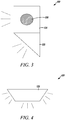
- FIG. 3 is a side view of the visual alarm device 100 and shows the second true side of the plurality of faces 124, the second downward side of the plurality of faces 123, and the third of the plurality of LEDs 108.
- a bottom half of the visual alarm detector 100 that includes at least the bottom side of the plurality of faces 122 can be angled downward to illuminate an area generally below the visual alarm device 100.
- one or both of the second true side of the plurality of faces 124 and the first true side of the plurality of faces 120 can be angled downward.
- FIG. 4 is a top view of the visual alarm device 100 and shows a top side of the plurality of faces 125.
- the visual alarm device 100 can have a generally trapezoidal shape.
- embodiments disclosed are not so limited, and it is to be understood that the visual alarm device 100 can be curved to have a half-circle shape or a half- ellipse shape.
- the flexible PCB 102 may not cover the top side of the plurality of faces 125.
- FIG. 5 is a bottom view of the visual alarm device 100 and shows the first downward side of the plurality of faces 121, the second downward side of the plurality of faces 123, the bottom side of the plurality of faces 122, and the fourth of the plurality of LEDs 110.
- the visual alarm device 100 can have a generally trapezoidal shape.
- the first downward side of the plurality of faces 121, the second downward side of the plurality of faces 123, and the bottom side of the plurality of faces 122 can be angled downward.
- FIG. 6 is a bottom view of a visual alarm device 100' in accordance with disclosed embodiments and shows a first downward side of a plurality of faces 121', a second downward side of the plurality of faces 123', a bottom side of the plurality of faces 122', a fourth of a plurality of LEDs 110' mounted in a fourth of a plurality of planes defined by the bottom side of the plurality of faces 122', a fifth of the plurality of LEDs 130 mounted in a fifth of the plurality of planes defined by the first downward side of the plurality of faces 121', and a sixth of the plurality of LEDs 132 mounted in a sixth of the plurality of planes defined by the second downward side of the plurality of faces 123'.
- FIG. 7 is a side view of the visual alarm device 100' and shows a second true side of the plurality of faces 124', a second downward side of the plurality of faces 123', a third of the plurality of LEDs 108', and the sixth of the plurality of LEDs 132.
- FIG. 8 is a perspective view of a frame 800 in accordance with disclosed embodiment.
- the frame 800 can include a frustum frame assembly 802 and a back frame assembly 804.
- the frustum frame assembly 802 may include a plurality of brackets and arms to define the plurality of faces 120, 124-126, and the frustum frame assembly 802 may include a generally frustum shape.
- the back frame assembly 804 may include a generally rectangular shape and can be attached to the frustum frame assembly 804.
- the back frame assembly 804 can be used to mount a visual alarm device to a wall or a ceiling.
- an intersection between the frustum frame assembly 802 and the back frame assembly 804 may define the plurality of faces 120, 124-126. Further still, in some embodiments, the frustum frame assembly 802 and the back frame assembly 804 may flex the flexible PCB 102 to orient the plurality of LEDs 104-110, 104'-110', 130, 132 in the plurality of directions for mounting the plurality of LEDs 104-110, 104'-110', 130, 132 in the plurality of planes defined by the plurality of faces 120-126, 120'-126' of the visual alarm device 100, 100'.
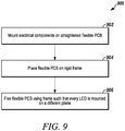
- FIG. 9 is a flow diagram of a method 900 for forming a visual alarm device in accordance with disclosed embodiments.
- the method 900 can include mounting electrical components (e.g. LEDs, wires, microprocessors, etc.) on a straightened or non-flexed flexible PCB (e.g. the PCB 102) as in 902, placing the flexible PCB over a rigid frame (e.g. the frame 800) as in 904, and using a shape of the rigid frame to flex the flexible PCB to orient a plurality of LEDs that are part of the electrical components in a plurality of directions for mounting the plurality of LEDs in a plurality of planes as in 906.
- each of the plurality of LEDs can flash simultaneously during an alarm or emergency situation.
- Embodiments disclosed herein are described without a reflector, thereby minimizing cost.
- embodiments disclosed herein are not so limited and may include a lens or a reflector, for example, a reflector that can reflect upward-projected light, for example, LED light emitted in an upward direction, downward, thereby increasing efficiency and complying with .
- UL 1638 which does not require light to be projected upward
Landscapes
- Engineering & Computer Science (AREA)
- Physics & Mathematics (AREA)
- General Physics & Mathematics (AREA)
- Microelectronics & Electronic Packaging (AREA)
- Mechanical Engineering (AREA)
- Theoretical Computer Science (AREA)
- Electromagnetism (AREA)
- General Engineering & Computer Science (AREA)
- Optics & Photonics (AREA)
- Arrangement Of Elements, Cooling, Sealing, Or The Like Of Lighting Devices (AREA)
- Fire Alarms (AREA)
- Non-Portable Lighting Devices Or Systems Thereof (AREA)
- Audible And Visible Signals (AREA)
Abstract
Description
- The present invention relates generally to alarm devices. More particularly, the present invention relates to visual alarm devices.
- Security systems are known to detect threats within a secured area, and such threats include events that represent a risk to human safety or a risk to assets.
- Security systems typically include one or more security sensors that detect the threats within the secured area. For example, smoke, motion, and/or intrusion sensors are distributed throughout the secured area in order to detect the threats. Furthermore, security systems typically include notification appliances, such as sounders and visual alarm devices (i.e. strobe lights).
- Standards organizations, such as Underwriters Laboratories (UL), specify standards for alarm devices. For example, UL 1638 specifies a light pattern for light emitted by a visual alarm device in a strobe light fire protection notification system.
- Light patterns defined by known standards, such as UL 1638, are difficult to achieve. For example, known visual alarm devices that emit light patterns that comply with known standards (e.g. UL 1638) include a single light source and a complicated arrangement of lenses and reflectors. However, lenses and reflectors can add to a cost of the visual alarm device. Thus, there is a need for less expensive systems and methods that comply with known standards.
-
-
FIG. 1 is a perspective view of a visual alarm device in accordance with disclosed embodiments; -
FIG. 2 is a front view of a visual alarm device in accordance with disclosed embodiments; -
FIG. 3 is a side view of a visual alarm device in accordance with disclosed embodiments; -
FIG. 4 is a top view of a visual alarm device in accordance with disclosed embodiments; -
FIG. 5 is a bottom view of a visual alarm device in accordance with disclosed embodiments; -
FIG. 6 is a bottom view of a visual alarm device in accordance with disclosed embodiments; -
FIG. 7 is a side view of a visual alarm device in accordance with disclosed embodiments; -
FIG. 8 is a perspective view of a frame of a visual alarm device in accordance with disclosed embodiments; and -
FIG. 9 is a flow diagram of a method in accordance with disclosed embodiments. - While this invention is susceptible of an embodiment in many different forms, there are shown in the drawings and will be described herein in detail specific embodiments thereof with the understanding that the present disclosure is to be considered as an exemplification of the principles of the invention. It is not intended to limit the invention to the specific illustrated embodiments.
- Embodiments disclosed herein can include systems and methods for mounting a plurality of light emitting diodes (LEDs) for a visual alarm device in multiple planes on a single printed circuit board (PCB). For example, in some embodiments, the single PCB may comprise a flexible PCB, the plurality of LEDs can be mounted to the flexible PCB, and the flexible PCB can be mounted to a rigid frame or assembly. Furthermore, in some embodiments, the flexible PCB can flex to conform to a shape of the rigid frame or assembly such that each of the plurality of LEDs can be mounted in a respective one of a plurality of planes and oriented in a respective one of a plurality of directions to generate a light pattern. Further still, in some embodiments, each of the plurality of LEDs can be electrically coupled to one another via electrical components mounted to the flexible PCB.
- In some embodiments, the visual alarm device can include four LEDs, and each of the four LEDs can be mounted in a respective one of four different planes. In some embodiments, the visual alarm device can include six LEDs, and each of the six LEDs can be mounted in a respective one of six different planes. In any embodiment, because the plurality of LEDs can be mounted in the multiple planes, reflectors or lenses are not required for the visual alarm device to emit the light pattern that complies with UL 1638 and other known standards.
-
FIG. 1 is a perspective view of avisual alarm device 100 in accordance with disclosed embodiments. As seen inFIG. 1 , thevisual alarm device 100 can include aflexible PCB 102, a plurality of LEDs 104-110 mounted on theflexible PCB 102, and a plurality of faces 120-125 of thevisual alarm device 100. In some embodiments, wiring and circuitry may be printed on theflexible PCB 102 to electrically couple the plurality of LEDs 104-110 with one another, and in some embodiments, thevisual alarm device 100 can be mounted to a wall or ceiling that can be substantially parallel with a front side of the plurality offaces 126. When seen from the perspective view ofFIG. 1 , thevisual alarm device 100 can have a generally frustum shape. - In some embodiments, each of the plurality of LEDs 104-110 can be mounted in a respective one of a plurality of planes by, for exampling, flexing the
flexible PCB 102 to orient each of the plurality of LEDs 104-110 in a respective one of a plurality of directions. For example, a first of the plurality ofLEDs 104 can be mounted in a first of the plurality of planes defined by a first true side of the plurality offaces 120, a second of the plurality ofLEDs 106 can be mounted in a second of the plurality of planes defined by the front side of the plurality offaces 126, a third of the plurality ofLEDs 108 can be mounted in a third of the plurality of planes defined by a second true side of the plurality offaces 124, and a fourth of the plurality ofLEDs 110 can be mounted in a fourth of the plurality of planes defined by a bottom side of the plurality offaces 120. -
FIG. 2 is a front view of thevisual alarm device 100 and shows the first true side of the plurality offaces 120, the front side of the plurality offaces 126, the second true side of the plurality offaces 124, a first downward side of the plurality offaces 121, a second downward side of the plurality offaces 123, a bottom side of the plurality offaces 122, the first of the plurality ofLEDs 104, the second of the plurality ofLEDs 106, the third of the plurality ofLEDs 108, and the fourth of the plurality ofLEDs 110. When seen from the front view ofFIG. 2 , thevisual alarm device 100 can have a generally rectangular shape. -
FIG. 3 is a side view of thevisual alarm device 100 and shows the second true side of the plurality offaces 124, the second downward side of the plurality offaces 123, and the third of the plurality ofLEDs 108. As seen inFIG. 3 , a bottom half of thevisual alarm detector 100 that includes at least the bottom side of the plurality offaces 122 can be angled downward to illuminate an area generally below thevisual alarm device 100. Furthermore, in some embodiments one or both of the second true side of the plurality offaces 124 and the first true side of the plurality offaces 120 can be angled downward. -
FIG. 4 is a top view of thevisual alarm device 100 and shows a top side of the plurality offaces 125. When seen from the top view ofFIG. 4 , thevisual alarm device 100 can have a generally trapezoidal shape. However, embodiments disclosed are not so limited, and it is to be understood that thevisual alarm device 100 can be curved to have a half-circle shape or a half- ellipse shape. In some embodiments, theflexible PCB 102 may not cover the top side of the plurality offaces 125. -
FIG. 5 is a bottom view of thevisual alarm device 100 and shows the first downward side of the plurality offaces 121, the second downward side of the plurality offaces 123, the bottom side of the plurality offaces 122, and the fourth of the plurality ofLEDs 110. When seen from the bottom view ofFIG. 5 , thevisual alarm device 100 can have a generally trapezoidal shape. Furthermore, in some embodiments the first downward side of the plurality offaces 121, the second downward side of the plurality offaces 123, and the bottom side of the plurality offaces 122 can be angled downward. -
FIG. 6 is a bottom view of a visual alarm device 100' in accordance with disclosed embodiments and shows a first downward side of a plurality of faces 121', a second downward side of the plurality of faces 123', a bottom side of the plurality of faces 122', a fourth of a plurality of LEDs 110' mounted in a fourth of a plurality of planes defined by the bottom side of the plurality of faces 122', a fifth of the plurality ofLEDs 130 mounted in a fifth of the plurality of planes defined by the first downward side of the plurality of faces 121', and a sixth of the plurality ofLEDs 132 mounted in a sixth of the plurality of planes defined by the second downward side of the plurality of faces 123'. -
FIG. 7 is a side view of the visual alarm device 100' and shows a second true side of the plurality of faces 124', a second downward side of the plurality of faces 123', a third of the plurality of LEDs 108', and the sixth of the plurality ofLEDs 132. -
FIG. 8 is a perspective view of aframe 800 in accordance with disclosed embodiment. As seen inFIG. 8 , theframe 800 can include afrustum frame assembly 802 and aback frame assembly 804. In some embodiments, thefrustum frame assembly 802 may include a plurality of brackets and arms to define the plurality offaces 120, 124-126, and thefrustum frame assembly 802 may include a generally frustum shape. Furthermore, in some embodiments, theback frame assembly 804 may include a generally rectangular shape and can be attached to thefrustum frame assembly 804. In some embodiments, theback frame assembly 804 can be used to mount a visual alarm device to a wall or a ceiling. Furthermore, in some embodiments, an intersection between thefrustum frame assembly 802 and theback frame assembly 804 may define the plurality offaces 120, 124-126. Further still, in some embodiments, thefrustum frame assembly 802 and theback frame assembly 804 may flex theflexible PCB 102 to orient the plurality of LEDs 104-110, 104'-110', 130, 132 in the plurality of directions for mounting the plurality of LEDs 104-110, 104'-110', 130, 132 in the plurality of planes defined by the plurality of faces 120-126, 120'-126' of thevisual alarm device 100, 100'. -
FIG. 9 is a flow diagram of amethod 900 for forming a visual alarm device in accordance with disclosed embodiments. As seen inFIG. 9 , themethod 900 can include mounting electrical components (e.g. LEDs, wires, microprocessors, etc.) on a straightened or non-flexed flexible PCB (e.g. the PCB 102) as in 902, placing the flexible PCB over a rigid frame (e.g. the frame 800) as in 904, and using a shape of the rigid frame to flex the flexible PCB to orient a plurality of LEDs that are part of the electrical components in a plurality of directions for mounting the plurality of LEDs in a plurality of planes as in 906. Once connected electrically, each of the plurality of LEDs can flash simultaneously during an alarm or emergency situation. - Embodiments disclosed herein are described without a reflector, thereby minimizing cost. However, embodiments disclosed herein are not so limited and may include a lens or a reflector, for example, a reflector that can reflect upward-projected light, for example, LED light emitted in an upward direction, downward, thereby increasing efficiency and complying with . UL 1638, which does not require light to be projected upward
- Although a few embodiments have been described in detail above, other modifications are possible. For example, the logic flows described above do not require the particular order described or sequential order to achieve desirable results. Other steps may be provided, steps may be eliminated from the described flows, and other components may be added to or removed from the described systems. Other embodiments may be within the scope of the invention.
- From the foregoing, it will be observed that numerous variations and modifications may be effected without departing from the spirit and scope of the invention. It is to be understood that no limitation with respect to the specific system or method described herein is intended or should be inferred. It is, of course, intended to cover all such modifications as fall within the spirit and scope of the invention.
- The numbered paragraphs below form part of the disclosure:
- 1. A visual alarm device comprising:
- a plurality of light emitting diodes (LEDs) mounted on a printed circuit board (PCB) and configured to flash during an emergency situation;
- wherein each of the plurality of LEDs is mounted in a respective one of a plurality of planes.
- 2. The visual alarm device of 1 wherein the PCB is flexible.
- 3. The visual alarm device of 2 further comprising a frame.
- 4. The visual alarm device of 3 wherein the frame includes a frustum frame assembly having a frustum shape and a back frame assembly.
- 5. The visual alarm device of 4 wherein the PCB conforms to the frustum shape of the frustum frame assembly.
- 6. The visual alarm device of 5 wherein the plurality of LEDs includes four LEDs.
- 7. The visual alarm device of 6 wherein a first of the plurality of LEDs is mounted in a first of the plurality of planes defined by a first true side of a plurality of faces defined by the frustum shape.
- 8. The visual alarm device of 7 wherein a second of the plurality of LEDs is mounted in a second of the plurality of planes defined by a second true side of the plurality of faces defined by the frustum shape.
- 9. The visual alarm device of 8 wherein a third of the plurality of LEDs is mounted in a third of the plurality of planes defined by a front side of the plurality of faces defined by the frustum shape.
- 10. The visual alarm device of 9 wherein a fourth of the plurality of LEDs is mounted in a fourth of the plurality of planes defined by a bottom side of the plurality of faces defined by an intersection between the frustum frame assembly and the back frame assembly.
- 11. The visual alarm device of 5 wherein the plurality of LEDs includes six LEDs.
- 12. The visual alarm device of 11 wherein a first of the plurality of LEDs is mounted in a first of the plurality of planes defined by a first true side of a plurality of faces defined by the frustum shape, wherein a second of the plurality of LEDs is mounted in a second of the plurality of planes defined by a second true side of the plurality of faces defined by the frustum shape, wherein a third of the plurality of LEDs is mounted in a third of the plurality of planes defined by a front side of the plurality of faces defined by the frustum shape, wherein a fourth of the plurality of LEDs is mounted in a fourth of the plurality of planes defined by a bottom side of the plurality of faces defined by an intersection between the frustum frame assembly and the back frame assembly, and wherein a fifth of the plurality of LEDs is mounted in a fifth of the plurality of planes defined by a first downward side of the plurality of faces defined by the intersection between the frustum frame assembly and the back frame assembly.
- 13. The visual alarm device of 12 wherein a sixth of the plurality of LEDs is mounted in a sixth of the plurality of planes defined by a second downward side of the plurality of faces defined by the intersection between the frustum frame assembly and the back frame assembly.
- 14. The visual alarm device of 1 further comprising a reflector positioned above the plurality of LEDs.
- 15. The visual alarm device of 1 further comprising a lens.
- 16. The visual alarm device of 1 having a non-circular shape.
- 17. The visual alarm device of 1 further comprising circuitry mounted on the PCB to electrically interconnect the plurality of LEDs.
- 18. The visual alarm device of 17 wherein the plurality of LEDs flash synchronously.
- 19. A visual alarm device comprising:
- a frame;
- a flexible printed circuit board (PCB) flexed to conform to a shape of the frame; and
- a plurality of light emitting diodes (LEDs) mounted on the flexible PCB and configured to flash during an emergency situation,
- wherein each of the plurality of LEDs is mounted in a respective one of a plurality of planes.
- 20. A method comprising:
- mounting a plurality of light emitting diodes (LEDs) on a straightened flexible printed circuit board (PCB);
- placing the flexible PCB over a rigid frame; and
- using a shape of the rigid frame to flex the flexible PCB to orient the plurality of LEDs in a plurality of directions for mounting the plurality of LEDs in a plurality of planes.
Claims (15)
- A visual alarm device comprising:a plurality of light emitting diodes (LEDs) mounted on a printed circuit board (PCB) and configured to flash during an emergency situation;wherein each of the plurality of LEDs is mounted in a respective one of a plurality of planes.
- The visual alarm device of claim 1 wherein the PCB is flexible.
- The visual alarm device of claim 2 further comprising a frame.
- The visual alarm device of claim 3 wherein the frame includes a frustum frame assembly having a frustum shape and a back frame assembly.
- The visual alarm device of claim 4 wherein the PCB conforms to the frustum shape of the frustum frame assembly.
- The visual alarm device of claim 5 wherein the plurality of LEDs includes four LEDs.
- The visual alarm device of claim 6 wherein a first of the plurality of LEDs is mounted in a first of the plurality of planes defined by a first true side of a plurality of faces defined by the frustum shape.
- The visual alarm device of claim 7 wherein a second of the plurality of LEDs is mounted in a second of the plurality of planes defined by a second true side of the plurality of faces defined by the frustum shape.
- The visual alarm device of claim 8 wherein a third of the plurality of LEDs is mounted in a third of the plurality of planes defined by a front side of the plurality of faces defined by the frustum shape.
- The visual alarm device of claim 9 wherein a fourth of the plurality of LEDs is mounted in a fourth of the plurality of planes defined by a bottom side of the plurality of faces defined by an intersection between the frustum frame assembly and the back frame assembly.
- The visual alarm device of claim 5 wherein the plurality of LEDs includes six LEDs.
- The visual alarm device of claim 11 wherein a first of the plurality of LEDs is mounted in a first of the plurality of planes defined by a first true side of a plurality of faces defined by the frustum shape, wherein a second of the plurality of LEDs is mounted in a second of the plurality of planes defined by a second true side of the plurality of faces defined by the frustum shape, wherein a third of the plurality of LEDs is mounted in a third of the plurality of planes defined by a front side of the plurality of faces defined by the frustum shape, wherein a fourth of the plurality of LEDs is mounted in a fourth of the plurality of planes defined by a bottom side of the plurality of faces defined by an intersection between the frustum frame assembly and the back frame assembly, and wherein a fifth of the plurality of LEDs is mounted in a fifth of the plurality of planes defined by a first downward side of the plurality of faces defined by the intersection between the frustum frame assembly and the back frame assembly.
- The visual alarm device of claim 12 wherein a sixth of the plurality of LEDs is mounted in a sixth of the plurality of planes defined by a second downward side of the plurality of faces defined by the intersection between the frustum frame assembly and the back frame assembly.
- The visual alarm device of claim 1 further comprising a reflector positioned above the plurality of LEDs.
- The visual alarm device of claim 1 further comprising a lens.
Applications Claiming Priority (1)
| Application Number | Priority Date | Filing Date | Title |
|---|---|---|---|
| US15/854,326 US10249155B1 (en) | 2017-12-26 | 2017-12-26 | Systems and methods for mounting light emitting diodes for a visual alarm device in multiple planes |
Publications (2)
| Publication Number | Publication Date |
|---|---|
| EP3506224A1 true EP3506224A1 (en) | 2019-07-03 |
| EP3506224B1 EP3506224B1 (en) | 2025-10-29 |
Family
ID=63452505
Family Applications (1)
| Application Number | Title | Priority Date | Filing Date |
|---|---|---|---|
| EP18191919.2A Active EP3506224B1 (en) | 2017-12-26 | 2018-08-31 | Systems for mounting light emitting diodes for a visual alarm device in multiple planes |
Country Status (2)
| Country | Link |
|---|---|
| US (2) | US10249155B1 (en) |
| EP (1) | EP3506224B1 (en) |
Families Citing this family (2)
| Publication number | Priority date | Publication date | Assignee | Title |
|---|---|---|---|---|
| US10249155B1 (en) * | 2017-12-26 | 2019-04-02 | Honeywell International Inc. | Systems and methods for mounting light emitting diodes for a visual alarm device in multiple planes |
| CN112284442B (en) * | 2020-12-29 | 2021-03-26 | 苏州天准科技股份有限公司 | Automatic visual inspection device of flexible circuit board |
Citations (5)
| Publication number | Priority date | Publication date | Assignee | Title |
|---|---|---|---|---|
| US5149190A (en) * | 1989-05-24 | 1992-09-22 | Bay Industrial And Mine Tech Inc. | Portable safety device |
| US20100109897A1 (en) * | 2007-10-31 | 2010-05-06 | Christian Hohler | Warning light for optically displaying at least one operating state |
| KR20100011965U (en) * | 2009-06-01 | 2010-12-09 | 이재구 | Flashing visual alarm using LED module |
| US20140043169A1 (en) * | 2012-08-07 | 2014-02-13 | Chun-Ming Wang | Warning lamp |
| CN107221113A (en) * | 2017-07-31 | 2017-09-29 | 中国民用航空总局第二研究所 | A kind of multi-functional overhead transmission line aviation alarming device and its assemble method |
Family Cites Families (12)
| Publication number | Priority date | Publication date | Assignee | Title |
|---|---|---|---|---|
| US5585783A (en) | 1994-06-28 | 1996-12-17 | Hall; Roger E. | Marker light utilizing light emitting diodes disposed on a flexible circuit board |
| US6183100B1 (en) * | 1997-10-17 | 2001-02-06 | Truck-Lite Co., Inc. | Light emitting diode 360° warning lamp |
| GB2330679B (en) | 1997-10-21 | 2002-04-24 | 911 Emergency Products Inc | Warning signal light |
| DE10239347A1 (en) | 2002-08-28 | 2004-03-18 | Fhf Funke + Huster Fernsig Gmbh | Signal lamp for indicating or warning of fault on machinery, flight path indication etc. contains enclosing flexible circuit board with individually energized luminescent elements, e.g. LEDs or organic LEDs (OLEDs) |
| US20050146884A1 (en) * | 2004-01-07 | 2005-07-07 | Goodrich Hella Aerospace Lighting Systems Gmbh | Light, particularly a warning light, for a vehicle |
| US20060132323A1 (en) * | 2004-09-27 | 2006-06-22 | Milex Technologies, Inc. | Strobe beacon |
| US20070035255A1 (en) | 2005-08-09 | 2007-02-15 | James Shuster | LED strobe for hazard protection systems |
| JP4642129B2 (en) * | 2008-11-06 | 2011-03-02 | ローム株式会社 | LED lamp |
| US20140104054A1 (en) * | 2012-10-15 | 2014-04-17 | Code 3, Inc. | Beacon with flashing and continuously illuminated leds |
| CN105940259B (en) * | 2014-01-29 | 2019-10-29 | 飞利浦照明控股有限公司 | LED bulb |
| US9533742B2 (en) * | 2014-04-01 | 2017-01-03 | Randal A. Deven | Marine navigation light apparatuses and methods of making the same |
| US10249155B1 (en) * | 2017-12-26 | 2019-04-02 | Honeywell International Inc. | Systems and methods for mounting light emitting diodes for a visual alarm device in multiple planes |
-
2017
- 2017-12-26 US US15/854,326 patent/US10249155B1/en active Active
-
2018
- 2018-08-31 EP EP18191919.2A patent/EP3506224B1/en active Active
-
2019
- 2019-03-27 US US16/366,205 patent/US11011030B2/en active Active
Patent Citations (5)
| Publication number | Priority date | Publication date | Assignee | Title |
|---|---|---|---|---|
| US5149190A (en) * | 1989-05-24 | 1992-09-22 | Bay Industrial And Mine Tech Inc. | Portable safety device |
| US20100109897A1 (en) * | 2007-10-31 | 2010-05-06 | Christian Hohler | Warning light for optically displaying at least one operating state |
| KR20100011965U (en) * | 2009-06-01 | 2010-12-09 | 이재구 | Flashing visual alarm using LED module |
| US20140043169A1 (en) * | 2012-08-07 | 2014-02-13 | Chun-Ming Wang | Warning lamp |
| CN107221113A (en) * | 2017-07-31 | 2017-09-29 | 中国民用航空总局第二研究所 | A kind of multi-functional overhead transmission line aviation alarming device and its assemble method |
Also Published As
| Publication number | Publication date |
|---|---|
| EP3506224B1 (en) | 2025-10-29 |
| US11011030B2 (en) | 2021-05-18 |
| US20190221085A1 (en) | 2019-07-18 |
| US10249155B1 (en) | 2019-04-02 |
Similar Documents
| Publication | Publication Date | Title |
|---|---|---|
| US11011030B2 (en) | Systems and methods for mounting light emitting diodes for a visual alarm device in multiple planes | |
| US8915613B2 (en) | Light emitting diode luminaire device and system | |
| EP1923620A1 (en) | Solid-state strip lighting system for assembly efficiency and variable beam angle with integral heatsink | |
| CN108692289B (en) | Folded heat sink with electrical connection protection | |
| US20200080709A1 (en) | Lighting arrangement | |
| US9215793B2 (en) | System and method for connecting LED devices | |
| US20160284177A1 (en) | Addressable light emitting diode lighting strip and methods, uses, and systems thereof | |
| EP3610195A1 (en) | Notification device for a surface of a building interior | |
| EP3261419A3 (en) | Method of hardware migration for replacing controllers | |
| US9146024B2 (en) | LED lighting module, LED lighting system and LED lighting retrofit kit | |
| CO2018011419A2 (en) | Modular and expandable fire suppression systems and methods | |
| US20130194806A1 (en) | LED Lighting Module | |
| JP6736857B2 (en) | LED emergency light combination type lighting equipment | |
| US9322528B2 (en) | Reflector arrays for lighting devices | |
| CA3062276A1 (en) | Wall mount light fixture with external sensor housing | |
| WO2017119727A3 (en) | Camera module | |
| GB2455723A (en) | Automatically activated illumination device | |
| US20180038573A1 (en) | Light shield | |
| JP2019053879A (en) | Light source module and lighting device | |
| EP3651557B1 (en) | Light emitting diode device | |
| RU163679U1 (en) | LED LAMP | |
| US20130162434A1 (en) | Signal apparatus for an alarm installation, alarm installation and method for operating the signal apparatus | |
| JP7113241B2 (en) | Lighting system and lighting control method | |
| CN107002956B (en) | Equipment Stands and Lightstrips for Lightstrips | |
| JP3152991U (en) | Light reflection unit and light emitting diode lamp provided with the same |
Legal Events
| Date | Code | Title | Description |
|---|---|---|---|
| PUAI | Public reference made under article 153(3) epc to a published international application that has entered the european phase |
Free format text: ORIGINAL CODE: 0009012 |
|
| STAA | Information on the status of an ep patent application or granted ep patent |
Free format text: STATUS: REQUEST FOR EXAMINATION WAS MADE |
|
| 17P | Request for examination filed |
Effective date: 20180831 |
|
| AK | Designated contracting states |
Kind code of ref document: A1 Designated state(s): AL AT BE BG CH CY CZ DE DK EE ES FI FR GB GR HR HU IE IS IT LI LT LU LV MC MK MT NL NO PL PT RO RS SE SI SK SM TR |
|
| AX | Request for extension of the european patent |
Extension state: BA ME |
|
| STAA | Information on the status of an ep patent application or granted ep patent |
Free format text: STATUS: EXAMINATION IS IN PROGRESS |
|
| 17Q | First examination report despatched |
Effective date: 20210215 |
|
| P01 | Opt-out of the competence of the unified patent court (upc) registered |
Effective date: 20230523 |
|
| REG | Reference to a national code |
Ref country code: DE Ref legal event code: R079 Free format text: PREVIOUS MAIN CLASS: G08B0005380000 Ipc: F21K0009000000 Ref document number: 602018086690 Country of ref document: DE |
|
| GRAP | Despatch of communication of intention to grant a patent |
Free format text: ORIGINAL CODE: EPIDOSNIGR1 |
|
| STAA | Information on the status of an ep patent application or granted ep patent |
Free format text: STATUS: GRANT OF PATENT IS INTENDED |
|
| RIC1 | Information provided on ipc code assigned before grant |
Ipc: F21K 9/00 20160101AFI20250603BHEP |
|
| INTG | Intention to grant announced |
Effective date: 20250612 |
|
| GRAS | Grant fee paid |
Free format text: ORIGINAL CODE: EPIDOSNIGR3 |
|
| GRAA | (expected) grant |
Free format text: ORIGINAL CODE: 0009210 |
|
| STAA | Information on the status of an ep patent application or granted ep patent |
Free format text: STATUS: THE PATENT HAS BEEN GRANTED |
|
| AK | Designated contracting states |
Kind code of ref document: B1 Designated state(s): AL AT BE BG CH CY CZ DE DK EE ES FI FR GB GR HR HU IE IS IT LI LT LU LV MC MK MT NL NO PL PT RO RS SE SI SK SM TR |
|
| REG | Reference to a national code |
Ref country code: CH Ref legal event code: F10 Free format text: ST27 STATUS EVENT CODE: U-0-0-F10-F00 (AS PROVIDED BY THE NATIONAL OFFICE) Effective date: 20251029 Ref country code: GB Ref legal event code: FG4D |
|
| REG | Reference to a national code |
Ref country code: IE Ref legal event code: FG4D |
|
| REG | Reference to a national code |
Ref country code: DE Ref legal event code: R096 Ref document number: 602018086690 Country of ref document: DE |
|
| REG | Reference to a national code |
Ref country code: NL Ref legal event code: MP Effective date: 20251029 |
|
| PG25 | Lapsed in a contracting state [announced via postgrant information from national office to epo] |
Ref country code: ES Free format text: LAPSE BECAUSE OF FAILURE TO SUBMIT A TRANSLATION OF THE DESCRIPTION OR TO PAY THE FEE WITHIN THE PRESCRIBED TIME-LIMIT Effective date: 20251029 |
|
| REG | Reference to a national code |
Ref country code: LT Ref legal event code: MG9D |
|
| PG25 | Lapsed in a contracting state [announced via postgrant information from national office to epo] |
Ref country code: NO Free format text: LAPSE BECAUSE OF FAILURE TO SUBMIT A TRANSLATION OF THE DESCRIPTION OR TO PAY THE FEE WITHIN THE PRESCRIBED TIME-LIMIT Effective date: 20260129 |
|
| PG25 | Lapsed in a contracting state [announced via postgrant information from national office to epo] |
Ref country code: FI Free format text: LAPSE BECAUSE OF FAILURE TO SUBMIT A TRANSLATION OF THE DESCRIPTION OR TO PAY THE FEE WITHIN THE PRESCRIBED TIME-LIMIT Effective date: 20251029 Ref country code: AT Free format text: LAPSE BECAUSE OF FAILURE TO SUBMIT A TRANSLATION OF THE DESCRIPTION OR TO PAY THE FEE WITHIN THE PRESCRIBED TIME-LIMIT Effective date: 20251029 Ref country code: HR Free format text: LAPSE BECAUSE OF FAILURE TO SUBMIT A TRANSLATION OF THE DESCRIPTION OR TO PAY THE FEE WITHIN THE PRESCRIBED TIME-LIMIT Effective date: 20251029 |
|
| REG | Reference to a national code |
Ref country code: AT Ref legal event code: MK05 Ref document number: 1851899 Country of ref document: AT Kind code of ref document: T Effective date: 20251029 |
|
| PG25 | Lapsed in a contracting state [announced via postgrant information from national office to epo] |
Ref country code: NL Free format text: LAPSE BECAUSE OF FAILURE TO SUBMIT A TRANSLATION OF THE DESCRIPTION OR TO PAY THE FEE WITHIN THE PRESCRIBED TIME-LIMIT Effective date: 20251029 |
|
| PG25 | Lapsed in a contracting state [announced via postgrant information from national office to epo] |
Ref country code: RS Free format text: LAPSE BECAUSE OF FAILURE TO SUBMIT A TRANSLATION OF THE DESCRIPTION OR TO PAY THE FEE WITHIN THE PRESCRIBED TIME-LIMIT Effective date: 20260129 |
|
| PG25 | Lapsed in a contracting state [announced via postgrant information from national office to epo] |
Ref country code: IS Free format text: LAPSE BECAUSE OF FAILURE TO SUBMIT A TRANSLATION OF THE DESCRIPTION OR TO PAY THE FEE WITHIN THE PRESCRIBED TIME-LIMIT Effective date: 20260228 |
|
| PG25 | Lapsed in a contracting state [announced via postgrant information from national office to epo] |
Ref country code: PT Free format text: LAPSE BECAUSE OF FAILURE TO SUBMIT A TRANSLATION OF THE DESCRIPTION OR TO PAY THE FEE WITHIN THE PRESCRIBED TIME-LIMIT Effective date: 20260302 |
|
| PG25 | Lapsed in a contracting state [announced via postgrant information from national office to epo] |
Ref country code: PL Free format text: LAPSE BECAUSE OF FAILURE TO SUBMIT A TRANSLATION OF THE DESCRIPTION OR TO PAY THE FEE WITHIN THE PRESCRIBED TIME-LIMIT Effective date: 20251029 |
|
| PG25 | Lapsed in a contracting state [announced via postgrant information from national office to epo] |
Ref country code: LV Free format text: LAPSE BECAUSE OF FAILURE TO SUBMIT A TRANSLATION OF THE DESCRIPTION OR TO PAY THE FEE WITHIN THE PRESCRIBED TIME-LIMIT Effective date: 20251029 |
|
| PG25 | Lapsed in a contracting state [announced via postgrant information from national office to epo] |
Ref country code: BG Free format text: LAPSE BECAUSE OF FAILURE TO SUBMIT A TRANSLATION OF THE DESCRIPTION OR TO PAY THE FEE WITHIN THE PRESCRIBED TIME-LIMIT Effective date: 20251029 |
|
| PG25 | Lapsed in a contracting state [announced via postgrant information from national office to epo] |
Ref country code: LT Free format text: LAPSE BECAUSE OF FAILURE TO SUBMIT A TRANSLATION OF THE DESCRIPTION OR TO PAY THE FEE WITHIN THE PRESCRIBED TIME-LIMIT Effective date: 20251029 |
|
| PG25 | Lapsed in a contracting state [announced via postgrant information from national office to epo] |
Ref country code: SM Free format text: LAPSE BECAUSE OF FAILURE TO SUBMIT A TRANSLATION OF THE DESCRIPTION OR TO PAY THE FEE WITHIN THE PRESCRIBED TIME-LIMIT Effective date: 20251029 |
|
| PG25 | Lapsed in a contracting state [announced via postgrant information from national office to epo] |
Ref country code: DK Free format text: LAPSE BECAUSE OF FAILURE TO SUBMIT A TRANSLATION OF THE DESCRIPTION OR TO PAY THE FEE WITHIN THE PRESCRIBED TIME-LIMIT Effective date: 20251029 |
|
| PG25 | Lapsed in a contracting state [announced via postgrant information from national office to epo] |
Ref country code: IT Free format text: LAPSE BECAUSE OF FAILURE TO SUBMIT A TRANSLATION OF THE DESCRIPTION OR TO PAY THE FEE WITHIN THE PRESCRIBED TIME-LIMIT Effective date: 20251029 |
|
| PG25 | Lapsed in a contracting state [announced via postgrant information from national office to epo] |
Ref country code: EE Free format text: LAPSE BECAUSE OF FAILURE TO SUBMIT A TRANSLATION OF THE DESCRIPTION OR TO PAY THE FEE WITHIN THE PRESCRIBED TIME-LIMIT Effective date: 20251029 |
|
| PG25 | Lapsed in a contracting state [announced via postgrant information from national office to epo] |
Ref country code: CZ Free format text: LAPSE BECAUSE OF FAILURE TO SUBMIT A TRANSLATION OF THE DESCRIPTION OR TO PAY THE FEE WITHIN THE PRESCRIBED TIME-LIMIT Effective date: 20251029 |
|
| PG25 | Lapsed in a contracting state [announced via postgrant information from national office to epo] |
Ref country code: SK Free format text: LAPSE BECAUSE OF FAILURE TO SUBMIT A TRANSLATION OF THE DESCRIPTION OR TO PAY THE FEE WITHIN THE PRESCRIBED TIME-LIMIT Effective date: 20251029 |
|
| PG25 | Lapsed in a contracting state [announced via postgrant information from national office to epo] |
Ref country code: SE Free format text: LAPSE BECAUSE OF FAILURE TO SUBMIT A TRANSLATION OF THE DESCRIPTION OR TO PAY THE FEE WITHIN THE PRESCRIBED TIME-LIMIT Effective date: 20251029 |