EP3506156A1 - Method and apparatus for detecting lane line, and medium - Google Patents
Method and apparatus for detecting lane line, and medium Download PDFInfo
- Publication number
- EP3506156A1 EP3506156A1 EP18215853.5A EP18215853A EP3506156A1 EP 3506156 A1 EP3506156 A1 EP 3506156A1 EP 18215853 A EP18215853 A EP 18215853A EP 3506156 A1 EP3506156 A1 EP 3506156A1
- Authority
- EP
- European Patent Office
- Prior art keywords
- image
- lane line
- generating
- generate
- original image
- Prior art date
- Legal status (The legal status is an assumption and is not a legal conclusion. Google has not performed a legal analysis and makes no representation as to the accuracy of the status listed.)
- Withdrawn
Links
Images




Classifications
-
- G—PHYSICS
- G06—COMPUTING OR CALCULATING; COUNTING
- G06V—IMAGE OR VIDEO RECOGNITION OR UNDERSTANDING
- G06V10/00—Arrangements for image or video recognition or understanding
- G06V10/20—Image preprocessing
- G06V10/28—Quantising the image, e.g. histogram thresholding for discrimination between background and foreground patterns
-
- G—PHYSICS
- G06—COMPUTING OR CALCULATING; COUNTING
- G06F—ELECTRIC DIGITAL DATA PROCESSING
- G06F18/00—Pattern recognition
- G06F18/20—Analysing
- G06F18/21—Design or setup of recognition systems or techniques; Extraction of features in feature space; Blind source separation
- G06F18/214—Generating training patterns; Bootstrap methods, e.g. bagging or boosting
-
- G—PHYSICS
- G06—COMPUTING OR CALCULATING; COUNTING
- G06T—IMAGE DATA PROCESSING OR GENERATION, IN GENERAL
- G06T5/00—Image enhancement or restoration
- G06T5/70—Denoising; Smoothing
-
- G—PHYSICS
- G06—COMPUTING OR CALCULATING; COUNTING
- G06T—IMAGE DATA PROCESSING OR GENERATION, IN GENERAL
- G06T7/00—Image analysis
- G06T7/10—Segmentation; Edge detection
- G06T7/13—Edge detection
-
- G—PHYSICS
- G06—COMPUTING OR CALCULATING; COUNTING
- G06T—IMAGE DATA PROCESSING OR GENERATION, IN GENERAL
- G06T7/00—Image analysis
- G06T7/70—Determining position or orientation of objects or cameras
- G06T7/73—Determining position or orientation of objects or cameras using feature-based methods
- G06T7/74—Determining position or orientation of objects or cameras using feature-based methods involving reference images or patches
-
- G—PHYSICS
- G06—COMPUTING OR CALCULATING; COUNTING
- G06V—IMAGE OR VIDEO RECOGNITION OR UNDERSTANDING
- G06V10/00—Arrangements for image or video recognition or understanding
- G06V10/20—Image preprocessing
- G06V10/30—Noise filtering
-
- G—PHYSICS
- G06—COMPUTING OR CALCULATING; COUNTING
- G06V—IMAGE OR VIDEO RECOGNITION OR UNDERSTANDING
- G06V10/00—Arrangements for image or video recognition or understanding
- G06V10/40—Extraction of image or video features
- G06V10/46—Descriptors for shape, contour or point-related descriptors, e.g. scale invariant feature transform [SIFT] or bags of words [BoW]; Salient regional features
-
- G—PHYSICS
- G06—COMPUTING OR CALCULATING; COUNTING
- G06V—IMAGE OR VIDEO RECOGNITION OR UNDERSTANDING
- G06V10/00—Arrangements for image or video recognition or understanding
- G06V10/70—Arrangements for image or video recognition or understanding using pattern recognition or machine learning
- G06V10/77—Processing image or video features in feature spaces; using data integration or data reduction, e.g. principal component analysis [PCA] or independent component analysis [ICA] or self-organising maps [SOM]; Blind source separation
- G06V10/774—Generating sets of training patterns; Bootstrap methods, e.g. bagging or boosting
-
- G—PHYSICS
- G06—COMPUTING OR CALCULATING; COUNTING
- G06V—IMAGE OR VIDEO RECOGNITION OR UNDERSTANDING
- G06V10/00—Arrangements for image or video recognition or understanding
- G06V10/70—Arrangements for image or video recognition or understanding using pattern recognition or machine learning
- G06V10/82—Arrangements for image or video recognition or understanding using pattern recognition or machine learning using neural networks
-
- G—PHYSICS
- G06—COMPUTING OR CALCULATING; COUNTING
- G06V—IMAGE OR VIDEO RECOGNITION OR UNDERSTANDING
- G06V10/00—Arrangements for image or video recognition or understanding
- G06V10/98—Detection or correction of errors, e.g. by rescanning the pattern or by human intervention; Evaluation of the quality of the acquired patterns
-
- G—PHYSICS
- G06—COMPUTING OR CALCULATING; COUNTING
- G06V—IMAGE OR VIDEO RECOGNITION OR UNDERSTANDING
- G06V20/00—Scenes; Scene-specific elements
- G06V20/50—Context or environment of the image
- G06V20/56—Context or environment of the image exterior to a vehicle by using sensors mounted on the vehicle
- G06V20/588—Recognition of the road, e.g. of lane markings; Recognition of the vehicle driving pattern in relation to the road
-
- G—PHYSICS
- G08—SIGNALLING
- G08G—TRAFFIC CONTROL SYSTEMS
- G08G1/00—Traffic control systems for road vehicles
- G08G1/16—Anti-collision systems
- G08G1/167—Driving aids for lane monitoring, lane changing, e.g. blind spot detection
-
- G—PHYSICS
- G06—COMPUTING OR CALCULATING; COUNTING
- G06F—ELECTRIC DIGITAL DATA PROCESSING
- G06F18/00—Pattern recognition
- G06F18/20—Analysing
- G06F18/24—Classification techniques
- G06F18/241—Classification techniques relating to the classification model, e.g. parametric or non-parametric approaches
- G06F18/2413—Classification techniques relating to the classification model, e.g. parametric or non-parametric approaches based on distances to training or reference patterns
- G06F18/24133—Distances to prototypes
- G06F18/24137—Distances to cluster centroïds
- G06F18/2414—Smoothing the distance, e.g. radial basis function networks [RBFN]
-
- G—PHYSICS
- G06—COMPUTING OR CALCULATING; COUNTING
- G06T—IMAGE DATA PROCESSING OR GENERATION, IN GENERAL
- G06T2207/00—Indexing scheme for image analysis or image enhancement
- G06T2207/20—Special algorithmic details
- G06T2207/20081—Training; Learning
-
- G—PHYSICS
- G06—COMPUTING OR CALCULATING; COUNTING
- G06T—IMAGE DATA PROCESSING OR GENERATION, IN GENERAL
- G06T2207/00—Indexing scheme for image analysis or image enhancement
- G06T2207/30—Subject of image; Context of image processing
- G06T2207/30248—Vehicle exterior or interior
- G06T2207/30252—Vehicle exterior; Vicinity of vehicle
- G06T2207/30256—Lane; Road marking
-
- G—PHYSICS
- G06—COMPUTING OR CALCULATING; COUNTING
- G06V—IMAGE OR VIDEO RECOGNITION OR UNDERSTANDING
- G06V10/00—Arrangements for image or video recognition or understanding
- G06V10/20—Image preprocessing
- G06V10/24—Aligning, centring, orientation detection or correction of the image
- G06V10/247—Aligning, centring, orientation detection or correction of the image by affine transforms, e.g. correction due to perspective effects; Quadrilaterals, e.g. trapezoids
Definitions
- Embodiments of the present disclosure mainly relate to the field of image detection, and specifically to a method and apparatus for detecting a lane line, and a medium.
- the research and development of the high-precision map and the autonomous driving technology has been paid more attention.
- the absolute coordinate accuracy of the high-precision map is higher and the road information contained in the high-precision map is more abundant.
- the development of the high-precision map accelerates the implementation of the autonomous driving.
- the high-precision map can improve the safety and reliability of the autonomous driving.
- a vehicle needs to detect the lane lines in a road. For example, the accurate position coordinates of the lane line points on the lane lines need to be extracted from the road information captured by a vehicle mounted camera. However, since there is interference of light in the environment, the lane line points cannot be effectively extracted by only using the traditional computer vision algorithm. In addition, if the lane line points are classified using the deep learning algorithm which only uses, for example, a convolutional neural network, it is difficult to determine the accuracy of the positions of the lane lines.
- a solution of detecting a lane line is provided.
- the present disclosure provides a method for generating a lane line detection model.
- the method includes: detecting a lane line in an original image to generate a first image associated with a detected lane line; and acquiring a second image generated based on the original image and associated with marked lane line.
- the method further includes: generating at least one tag indicating whether the detected lane line is accurate, based on the first image and the second image; and training a classifier model for automatically identifying the lane line, based on the first image and the at least one tag.
- the present disclosure provides a method for detecting lane lines.
- the method includes: detecting a lane line in an original image to generate a first image associated with the detected lane line.
- the method further includes: inputting the first image into the classifier model according to the first aspect of the present disclosure, to automatically identify the lane line.
- the present disclosure provides an apparatus for generating a lane line detection model.
- the apparatus includes: a first image generating module, configured to detect a lane line in an original image to generate a first image associated with a detected lane line; a second image acquiring module, configured to acquire a second image generated based on the original image and associated with marked lane line; a tag generating module, configured to generate at least one tag indicating whether the detected lane line is accurate, based on the first image and the second image; and a model training module, configured to train a classifier model for automatically identifying the lane line, based on the first image and the at least one tag.
- the present disclosure provides an apparatus for detecting lane lines.
- the apparatus includes: a first image generating module, configured to detect a lane line in an original image to generate a first image associated with the detected lane line; and a model applying module, configured to input the first image into the classifier model according to the first aspect of the present disclosure, to automatically identify the lane line.
- the present disclosure provides a device.
- the device includes: one or more processors; and a storage device, configured to store one or more programs.
- the one or more programs when executed by the one or more processors, cause the one or more processors to implement the method according to the first aspect of the present disclosure.
- the present disclosure provides a device.
- the device includes: one or more processors; and a storage device, configured to store one or more programs.
- the one or more programs when executed by the one or more processors, cause the one or more processors to implement the method according to the second aspect of the present disclosure.
- the present disclosure provides a computer readable medium storing a computer program.
- the program when executed by a processor, implements the method according to the first aspect of the present disclosure.
- the present disclosure provides a computer readable medium storing a computer program.
- the program when executed by a processor, implements the method according to the second aspect of the present disclosure.
- the term “including” and similar terms thereof should be understood as open-ended (i.e., “including, but not limited to”).
- the term “based on” should be understood as “at least partially based on.”
- the term “an embodiment” or “the embodiment” should be understood as “at least one embodiment.”
- the terms “first,” “second,” and the like may refer to different or identical objects. Other explicit and implicit definitions may also be included hereinafter.
- the lane lines in the road are detected only through a traditional computer vision algorithm or only by deep learning.
- the solution in which the traditional computer vision algorithm is used has a low accuracy, and cannot satisfy the needs of the high-precision map and the autonomous driving.
- the lane lines in the road cannot be accurately detected.
- the solution of directly using the deep learning has a poor universality. Since the solution of using the deep learning is based on, for example, an end-to-end convolutional neural network, the solution has problems such as the dependence on the diversity of the training data, a high model complexity, and a slow computing speed, which makes the solution unsuitable for detecting the lane lines in the road in any situation (e.g., a computing device without support of a high-performance graphics processing unit (GPU)).
- GPU graphics processing unit
- the exemplary embodiments of the present disclosure propose a solution for detecting lane lines.
- the lane lines are automatically identified by combining the computer vision algorithm and the deep learning.
- whether the detected lane lines are accurate is determined based on an image associated with the detected lane lines (referred to as a first image hereinafter) and an image associated with the marked lane lines (referred to as a second image hereinafter), and at least one tag indicating whether the detected lane lines are accurate is generated.
- the classifier model for automatically identifying the lane lines is trained based on the first image and the at least one tag.
- the automatic identification for the lane lines is achieved by inputting the first image associated with the detected lane lines into the above trained classifier model.
- the solution of the present disclosure simultaneously has the simplicity of the computer vision algorithm and the powerful generalization capability of the deep learning.
- the lane line detection may be achieved in a simple and effective way, thereby improving the performances of the high-precision map and the autonomous driving.
- model may learn the correlation between the respective input and output from the training data. Thus, a corresponding output may be generated for a given input after the training is completed. It should be understood that the "model” may also be referred to as a "neural network,” a “learning model,” or a “learning network.”
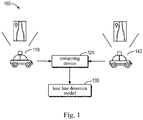
- Fig. 1 illustrates a schematic diagram of an exemplary environment 100 in which a plurality of embodiments of the present disclosure can be implemented.
- the lane line detection model 130 is generated by the computing device 120.
- the computing device 120 may generate the lane line detection model 130 based on training data.
- the acquisition entity 110 may be used to acquire the corresponding training data and provide the acquired training data to the computing device 120.
- the acquisition entity 110 may be a vehicle or a mobile robot having an acquisition device such as a camera.
- the computing device 120 may be implemented on the acquisition entity 110.
- the computing device 120 may be remote from the acquisition entity 110, and communicate with the acquisition entity 110 by means of a wired connection or wireless connection.
- the training data may include an original image.
- Fig. 2A illustrates a schematic diagram of an original image 200A according to some embodiments of the present disclosure.
- the original image 200A may be an image related to road information.
- the original image 200A may be an image containing road information and acquired by the acquisition entity 110 during driving.
- the original image 200A may be independent of the road information.
- the computing device 120 may detect the lane lines in the original image 200A to generate a first image associated with the detected lane lines. In some embodiments, the computing device 120 may detect the lane lines through a computer vision algorithm, and display the detected lane lines in the original image 200A, thus generating the first image 200B.
- the computing device 120 may use lane line points on the detected lane lines to show the detected lane lines.
- a lane line point may include one or more pixels.
- the computing device 120 may show the detected lane lines by changing the color of the pixels corresponding to the lane line points on the detected lane lines on the original image 200A.
- the first image 200B is generated.
- the computing device 120 may change the color of the pixels corresponding to the lane line points on the detected lane lines in the original image 200A to a color that does not appear or appear less in the original image 200A, so that the lane line points are distinguished from other graphic elements in the original image 200A to show the detected lane lines.
- Fig. 2B illustrates a schematic diagram of a the first image 200B according to some embodiments of the present disclosure.
- the first image 200B is an image in which the lane line points are used to show the detected lane lines on the original image 200A.
- the computing device 120 may acquire a second image generated based on the original image 200A and associated with the marked lane lines.
- the second image may be an image generated by marking the lane lines on the original image 200A.
- the marking operation may be completed by a user. Alternatively, the marking operation may be automatically completed by the computing device 120 without the user.
- Fig. 2C illustrates a schematic diagram of a the second image 200C according to some embodiments of the present disclosure.
- the second image 200C is an image in which the lane lines are marked on the original image 200A using dotted lines.
- the actual lane lines and the lane lines marked with the dotted lines are not coincident.
- the actual lane lines may be coincident with the lane lines marked with the dotted lines.
- the second image 200C may only retain the information related to the lane lines, to clearly mark the lane lines, which is a more suitable basis for determining whether the detected lane lines are accurate.
- the lane lines and other graphic elements may be set to colors that easily distinguish from each other. Specifically, the color of the lane lines may be set to white while the color of the other graphic elements may be set to black.
- the computing device 120 may generate at least one tag indicating whether the detected lane lines are accurate. In some embodiments, the computing device 120 may compare the first image 200B with the second image 200C, to determine whether the detected lane lines are accurate based on whether the first image 200B matches the second image 200C, and generate the at least one tag indicating whether the detected lane lines are accurate.
- the computing device 120 may determine whether the detected lane lines are accurate by determining whether the positions of the detected lane lines match the positions of the lane lines marked on the second image 200C, and generate the at least one tag indicating whether the detected lane lines are accurate. For example, the computing device 120 may determine whether the coordinates of the pixels of the lane line points on the detected lane lines in the first image 200B match the coordinate positions of the pixels of the lane lines marked on the second image 200C.
- the computing device 120 may train the classifier model 140 that is used for automatically identifying the lane lines.
- the computing device 120 may modify the classifier model 140 based on the first image 200B and the at least one tag, such that the trained classifier model 140 may accurately determine whether the detected lane lines in the first image 200B are accurate.
- the computing device 120 may detect the lane lines in the to-be-detected original image 200A to generate the first image 200B associated with the detected lane lines.
- the acquisition entity 110 may be used to acquire the corresponding training data and provide the acquired training data to the computing device 120.
- the acquisition entity 110, the to-be-detected original image 200A, and the approach of generating the first image 200B are respectively similar to the above acquisition entity 110, the above original image 200A, and the above approach of generating the first image 200B, and thus the description thereof is omitted herein.
- the computing device 120 may input the first image 200B into the trained classifier model 140.
- the trained classifier model 140 may determine whether the detected lane lines on the first image 200B are accurate, to automatically identify the lane lines.
- the solution of the present disclosure can not only accurately detect the lane lines in the road in a situation where there is the interference of light (e.g., strong light) in the environment or the lane lines are complex, but also be suitable for detecting the lane lines in the road in the computing device without a powerful graphics processing capability.
- light e.g., strong light
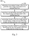
- Fig. 3 illustrates a flowchart of a process 300 of generating a lane line detection model according to the embodiments of the present disclosure.
- the process 300 may be implemented by the computing device 102.
- the computing device 120 detects the lane lines in the original image 200A, to generate the first image 200B associated with the detected lane lines.
- Block 310 may also be referred to as an image processing process.
- block 310 will be described in detail in combination with Fig. 4 .
- the computing device 120 acquires the second image 200C generated based on the original image 200A and associated with the marked lane lines.
- the second image 200C may be the image generated by marking the lane lines on the original image 200A.
- the marking operation may be completed by the user. Alternatively, the marking operation may be automatically completed by the computing device 120 without the user.
- Block 330 based on the first image 200B and the second image 200C, the computing device 120 generates the at least one tag indicating whether the detected lane lines are accurate.
- Block 330 may also be referred to as a tag generating process.
- block 330 will be described in detail in combination with Fig. 5 .
- the computing device 120 trains the classifier model that is used for automatically identifying the lane lines.
- the computing device 120 may modify the classifier model 140 based on the first image 200B and the at least one tag, such that the trained classifier model 140 may accurately determine whether the detected lane lines on the first image 200B are accurate.
- the generated lane line detection model may have the simplicity and the instantaneity benefiting from the computer vision algorithm, and simultaneously have the accuracy and the robustness benefiting from the deep learning.
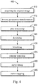
- Fig. 4 illustrates a flowchart of a process 400 of generating a the first image 200B according to some embodiments of the present disclosure. It will be appreciated that the process 400 may be considered as an exemplary implementation for block 310 in the process 300 described above.
- the computing device 120 obtains the original image 200A from the acquisition entity 110.
- the computing device 120 performs an inverse perspective transformation on the original image 200A to generate an inverse-perspective transformed image. It may be understood that due to the principle of perspective the parallel lines in the real world will become intersecting lines in an image based on the distance. Based on the principle of perspective, the interval between the two lane lines on a road becomes smaller at the far end of the original image 200A, which is disadvantageous to the detection for the lane lines. Thus, to counteract the influence of the perspective effect on the original image 200A, the computing device 120 may perform the inverse perspective transformation on the original image 200A to generate the inverse-perspective transformed image, which is suitable for detecting the lane lines.
- the computing device 120 performs gray processing on the inverse-perspective transformed image.
- the computing device 120 may perform the gray processing on the original image 200A to generate a grayed image.
- the gray processing performed on an image may remove the color of the image, and only retain the brightness of the image, thereby reducing the bytes of the image.
- the computing device 120 denoises the grayed image to generate denoised image.
- the computing device 120 may denoise the original image 200A to generate the denoised image.
- the denoising the image may remove the noise from the image, which makes the image smoother.
- the denoising may be achieved through algorithms such as Gaussian filtering or mean filtering.
- the computing device 120 binarizes the denoised image to generate a binary image.
- the computing device 120 may binarize the original image 200A to generate a binary image.
- the computing device 120 may binarize the grayed image to generate a binary image. binarizing an image may set the brightness values of the pixels in the image to 0 or 255, such that the bytes of the image is reduced and the image is more suitable for detecting the lane lines.
- the computing device 120 applies a contour detection (also referred to as edge detection) on the binary image to generate the contours of the lane lines.
- a contour detection also referred to as edge detection
- the computing device 120 applies the contour detection on the original image 200A to generate the contours of the lane lines.
- the contour detection on the image may retain important structural attributes of the lane lines, and remove unimportant or irrelevant information, such that the bytes of the image is further reduced and the image is more suitable for detecting the lane lines.
- the computing device 120 performs curve fitting on the generated contours of the lane lines to generate the curves representing the lane lines.
- the curve fitting on the contours of the lane lines may remove the deviation point on the contours of the lane lines.
- the computing device 120 may segment the generated curves.
- the computing device 120 may segment the curves into curve segments of 40 pixel lengths.
- the curve segments may correspond to the detected lane line points.
- a curve segment may correspond to one detected lane line point.
- the curve segment may correspond to a set of detected lane line points. In such case, the subsequent processing may be performed on the image based on the curve segments rather than the entire curve, thereby reducing the computations required for each image processing operation.
- the computing device 120 generates the first image by mapping the curves to the original image. For example, as described above, the computing device 120 may show the detected lane lines by changing the color of the pixels corresponding to the lane line points on the detected lane lines on the original image 200A, thus generating the first image 200B. Specifically, the computing device 120 may change the color of the pixels corresponding to the lane line points on the detected lane lines on the original image 200A to the color that does not appear or appear less in the original image 200A, to distinguish the lane liens from the other graphic elements in the original image 200A and show the lane lines.
- the operations in the process 400 are described in a particular order, but the operations may be performed in an order different from the described order, performed in parallel, or omitted.
- the computing device 120 may perform the inverse perspective transformation on the generated gray graphic after performing the gray processing on the original image 200A. In still some embodiments, the computing device 120 may not denoise the image.
- the first image 200B may be generated simply and effectively.
- the detected lane lines may be supplemented with the help of the original image 200A even in the situation where the lane lines cannot be accurately detected due to the interference of light in the environment or the lane lines are complex, thus improves the accuracy.
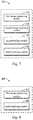
- Fig. 5 illustrates a flowchart of a process 500 of generating at least one tag according to some embodiments of the present disclosure. It will be appreciated that the process 500 may be considered as an exemplary implementation for block 330 in the process 300 described above.
- the computing device 120 compares the first image 200B with the second image 200C to determine whether the first image 200B matches the second image 200C. In some embodiments, the computing device 120 may compare the first image 200B with the second image 200C to obtain a similarity between the first image 200B and the second image 200C. In the situation where the similarity exceeds a predefined threshold, the computing device 120 may determine that the first image 200B matches the second image 200C.
- the computing device 120 may compare the positions of the detected lane lines in the first image 200B with the positions of the lane lines marked on the second image 200C to determine whether the first image 200B matches the second image 200C. Specifically, the computing device 120 may compare the coordinates of the pixels of the lane line points on the detected lane lines in the first image 200B with the coordinates of the pixels of the lane lines marked on the second image 200C. In the situation where the number of the coordinates of the pixels of the lane line points in the detected lane lines coincident with the coordinates of the pixels of the marked lane lines exceeds a predefined threshold, the computing device 120 may determine that the first image 200B matches the second image 200C.
- the computing device 120 may compare the positions on the original image 200A of the curves representing the lane lines with the positions of the lane lines marked on the second image 200C.
- the computing device 120 may divide the first image 200B into a first set of image blocks, each of which includes a portion of the detected lane lines. For example, in some embodiments, as described above, in the situation where the curves representing the lane lines are segmented, since the position of a curve segment on the original image 200A correspond to the position of a portion of the detected lane lines on the first image 200B, the computing device 120 may divide the first image 200B into the first set of image blocks based on the portion of the detected lane lines that corresponds to the curve segment. As described above, in some embodiments, the curve segments may correspond to the detected lane line points. In such case, the division approach may be understood as that the computing device 120 divides the first image 200B into the first set of image blocks based on the detected lane line points.
- the computing device 120 may generate an image block (also referred to as a partial view) surrounding a portion of the detected lane lines with the position of the portion of the detected lane lines on the first image 200B as a center.
- an image block also referred to as a partial view
- the corresponding portion of the detected lane lines also has the length of 40 pixels.
- the computing device 120 may select the pixels around the portion of the detected lane lines with the portion of the detected lane line as the center, to generate the image block of, for example, 64 ⁇ 64 pixels.
- the computing device 120 may divide the second image 200C into a second set of image blocks, each of which includes a portion of the marked lane lines. In this case, by comparing the corresponding image blocks in the first set of image blocks and the second set of image blocks, the computing device 120 may determine whether the corresponding image block matches. Alternatively, the computing device 120 may compare the position of the portion of the detected lane lines included in each image block in the first set of image blocks with the position of the portion of the marked lane lines included in the corresponding image block in the second set of image blocks.
- the computing device 120 may compare the coordinates of the pixels of the detected lane points included in the each image block in the first set of image blocks with the coordinates of the pixels of the marked lane lines included in the corresponding image block in the second set of image blocks. For the each image block, in the situation where the number of the coordinates of the pixels of the detected lane line points included in the image block coincident with the coordinates of the pixels of the marked lane lines (i.e., the corresponding coordinates are the same) exceeds a predefined threshold, the computing device 120 may determine that the image block matches the second image 200C.
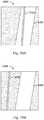
- Fig. 10A illustrates a schematic diagram of the matching between the image block 1000A and the second image 200C.
- the computing device 120 may determine that the image block matches the second image 200C.
- the image block 1000A may be used as a positive sample of the classifier model.
- Fig. 10B illustrates a schematic diagram of the matching between the image block 1000B and the second image 200C.
- the image block 1000B includes the detected lane line points 1010B.
- the computing device 120 may determine that the image block does not match the second image 200C.
- the image block 1000B may be used as a negative sample of the classifier model.
- the computing device 120 may compare the position of the curve segment corresponding to an image block in the first set of image blocks with the position of the portion of the marked lane lines included in the corresponding image block in the second set of image blocks.
- the computing device 120 may not divide the second image 200C, and directly and respectively compare the first set of image blocks with the second image 200C.
- the computing device 120 may directly and respectively compare the portion of the detected lane lines included in the each image block in the first set of image blocks with the second image 200C.
- the computing device 120 may directly and respectively compare the coordinates of the pixels of the detected lane points included in the each image block in the first set of image blocks with the second image 200C.
- the computing device 120 may directly and respectively compare the positions corresponding to the image blocks in the first set of image blocks with the second image 200C.
- the computing device 120 If it is determined that the first image 200B matches the second image 200C, then at block 520, the computing device 120 generates at least one tag indicating that the detected lane lines are accurate.
- the tag may indicate whether the first image 200B is a positive sample or a negative sample for the classifier model 140. The positive sample indicates that the first image 200B is detected as the lane lines. The negative sample indicates that the first image 200B is not detected as the lane lines.
- the computing device 120 may generate a tag indicating the corresponding portion of the lane lines included in the image block is accurate.
- the computing device 120 generates at least one tag indicating that the detected lane lines are inaccurate.
- the computing device 120 may generate a tag indicating the corresponding portion of the lane lines included in the image block is inaccurate. In this way, the at least one tag indicating whether the detected lane lines are accurate may be simply and effectively generated, to support the training on the classifier model.
- the first image 200B is inputted into the trained classifier model to automatically identify the lane lines.
- the classifier model has been trained using the first image 200B and the at least one tag indicating whether the detected lane lines on the first image 200B are accurate.
- the association between the first image 200B and the corresponding tag is generated. Therefore, during the application, based on the first image 200B and the association, the classifier model may generate a tag corresponding to the first image 200B, to indicate whether the detected lane lines on the first image 200B are accurate. Accordingly, the lane lines are automatically identified.
- the lane line detection may be achieved in a simple and effective way, thereby improving the performances of the high-precision map and the autonomous driving.
- Fig. 7 illustrates a schematic block diagram of an apparatus 700 for generating a lane line detection model according to the embodiments of the present disclosure.
- the apparatus 700 includes: a first image generating module 710, configured to detect a lane line in an original image to generate a first image associated with a detected lane line; a second image acquiring module 720, configured to acquire a second image generated based on the original image and associated with marked lane line; a tag generating module 730, configured to generate at least one tag indicating whether the detected lane line is accurate, based on the first image and the second image; and a model training module 740, configured to train a classifier model for automatically identifying the lane line, based on the first image and the at least one tag.
- the first image generating module 710 includes: an inverse perspective transformation module, configured to perform an inverse perspective transformation on the original image; and an inverse-perspective-transformed image generating module, configured to detect the lane line in an inverse-perspective transformed original image, to generate the first image.
- the first image generating module 710 includes: a gray processing module, configured to perform gray processing on the original image to generate a grayed original image; a binarization module, configured to binarize the grayed original image, to generate a binary image; and a binary image generating module, configured to detect the lane line in the binary image to generate the first image.
- the first image generating module 710 includes: a denoising module, configured to denoise the original image to generate a denoised image; and a denoised image generating module, configured to detect the lane line in the denoised image to generate the first image.
- the first image generating module 710 includes: a contour detection module, configured to apply a contour detection on the original image to generate a contour of the lane line; and a contour-detected image generating module, configured to generate the first image based on the contour.
- the first image generating module 710 includes: a curve fitting module, configured to perform curve fitting on the contour to generate a curve representing the lane line; and a curve-fitted image generating module, configured to generate the first image by mapping the curve to the original image.
- the tag generating module 730 includes: a first image dividing module, configured to divide the first image into a first set of image blocks, wherein each of the image blocks includes a portion of the detected lane line; a second image dividing module, configured to divide the second image into a second set of image blocks, wherein each of the image blocks includes a portion of the marked lane line; and a partial tag generating module, configured to generate a plurality of tags for a plurality of portions of the detected lane line by comparing corresponding image blocks in the first and second set of image blocks, wherein each of the tags indicates whether a corresponding portion of the detected lane line is accurate.
- Fig. 8 illustrates a schematic block diagram of an apparatus 800 for detecting a lane line according to the embodiments of the present disclosure.
- the apparatus 800 includes: a first image generating module 810, configured to detect a lane line in an original image to generate a first image associated with the detected lane line; and a model applying module 820, configured to input the first image into a trained classifier model to automatically identify the lane line.
- Fig. 9 shows a schematic block diagram of an exemplary device 900 capable of implementing various embodiments of the present disclosure.
- the device 900 may be used to implement the computing device 120 in Fig. 1 .
- the device 900 includes a central processing unit (CPU) 901 that may perform various appropriate actions and processing in accordance with computer program instructions stored in a read only memory (ROM) 902 or computer program instructions loaded into a random access memory (RAM) 903 from a storage unit 908.
- ROM read only memory
- RAM random access memory
- various programs and data required for the operation of the device 900 may also be stored.
- the CPU 901, the ROM 902, and the RAM 903 are connected to each other through a bus 904.
- An input/output (I/O) interface 905 is also coupled to the bus 904.
- a plurality of components in the device 900 are coupled to the I/O interface 905, including: an input unit 906, such as a keyboard or a mouse; an output unit 907, such as various types of displays, or speakers; the storage unit 908, such as a disk or an optical disk; and a communication unit 909 such as a network card, a modem, or a wireless communication transceiver.
- the communication unit 909 allows the device 900 to exchange information/data with other devices over a computer network such as the Internet and/or various telecommunication networks.
- the processing unit 901 performs the various methods and processes described above, such as the process 300, 400, 500 and/or the process 600.
- the process 800 and/or the process 900 may be implemented as a computer software program that is tangibly embodied in a machine readable medium, such as the storage unit 908.
- some or all of the computer programs may be loaded and/or installed onto the device 900 via the ROM 902 and/or the communication unit 909.
- the CPU 901 may be configured to perform the process 300, 400, 500 and/or the process 600 by any other suitable means (e.g., by means of firmware).
- FPGA Field Programmable Gate Array
- ASIC Application Specific Integrated Circuit
- ASSP Application Specific Standard Product
- SOC System on Chip
- CPLD Complex Programmable Logic Device
- Program codes for implementing the method of the present disclosure may be written in any combination of one or more programming languages. These program codes may be provided to a processor or controller of a general purpose computer, special purpose computer or other programmable data processing apparatus such that the program codes, when executed by the processor or controller, enables the functions/operations specified in the flowcharts and/or block diagrams being implemented.
- the program codes may execute entirely on the machine, partly on the machine, as a stand-alone software package partly on the machine and partly on the remote machine, or entirely on the remote machine or server.
- the machine readable medium may be a tangible medium that may contain or store programs for use by or in connection with an instruction execution system, apparatus, or device.
- the machine readable medium may be a machine readable signal medium or a machine readable storage medium.
- the machine readable medium may include, but is not limited to, an electronic, magnetic, optical, electromagnetic, infrared, or semiconductor system, apparatus, or device, or any suitable combination of the foregoing.
- machine readable storage medium may include an electrical connection based on one or more wires, portable computer disk, hard disk, random access memory (RAM), read only memory (ROM), erasable programmable read only memory (EPROM or flash memory), optical fiber, portable compact disk read only memory (CD-ROM), optical storage device, magnetic storage device, or any suitable combination of the foregoing.
- RAM random access memory
- ROM read only memory
- EPROM or flash memory erasable programmable read only memory
- CD-ROM portable compact disk read only memory
- magnetic storage device magnetic storage device, or any suitable combination of the foregoing.
Landscapes
- Engineering & Computer Science (AREA)
- Theoretical Computer Science (AREA)
- Physics & Mathematics (AREA)
- General Physics & Mathematics (AREA)
- Multimedia (AREA)
- Computer Vision & Pattern Recognition (AREA)
- Evolutionary Computation (AREA)
- Artificial Intelligence (AREA)
- General Health & Medical Sciences (AREA)
- Software Systems (AREA)
- Health & Medical Sciences (AREA)
- Computing Systems (AREA)
- Medical Informatics (AREA)
- Databases & Information Systems (AREA)
- Data Mining & Analysis (AREA)
- Quality & Reliability (AREA)
- Life Sciences & Earth Sciences (AREA)
- General Engineering & Computer Science (AREA)
- Bioinformatics & Cheminformatics (AREA)
- Bioinformatics & Computational Biology (AREA)
- Evolutionary Biology (AREA)
- Image Analysis (AREA)
- Biomedical Technology (AREA)
- Biophysics (AREA)
- Computational Linguistics (AREA)
- Molecular Biology (AREA)
- Mathematical Physics (AREA)
- Traffic Control Systems (AREA)
Abstract
Description
- Embodiments of the present disclosure mainly relate to the field of image detection, and specifically to a method and apparatus for detecting a lane line, and a medium.
- At present, the research and development of the high-precision map and the autonomous driving technology has been paid more attention. Compared with the traditional electronic map, the absolute coordinate accuracy of the high-precision map is higher and the road information contained in the high-precision map is more abundant. The development of the high-precision map accelerates the implementation of the autonomous driving. For example, the high-precision map can improve the safety and reliability of the autonomous driving.
- In the high-precision map and the autonomous driving, out of the needs for the high-precision map and the road perception, a vehicle needs to detect the lane lines in a road. For example, the accurate position coordinates of the lane line points on the lane lines need to be extracted from the road information captured by a vehicle mounted camera. However, since there is interference of light in the environment, the lane line points cannot be effectively extracted by only using the traditional computer vision algorithm. In addition, if the lane line points are classified using the deep learning algorithm which only uses, for example, a convolutional neural network, it is difficult to determine the accuracy of the positions of the lane lines.
- According to exemplary embodiments of the present disclosure, a solution of detecting a lane line is provided.
- In a first aspect, the present disclosure provides a method for generating a lane line detection model. The method includes: detecting a lane line in an original image to generate a first image associated with a detected lane line; and acquiring a second image generated based on the original image and associated with marked lane line. The method further includes: generating at least one tag indicating whether the detected lane line is accurate, based on the first image and the second image; and training a classifier model for automatically identifying the lane line, based on the first image and the at least one tag.
- In a second aspect, the present disclosure provides a method for detecting lane lines. The method includes: detecting a lane line in an original image to generate a first image associated with the detected lane line. The method further includes: inputting the first image into the classifier model according to the first aspect of the present disclosure, to automatically identify the lane line.
- In a third aspect, the present disclosure provides an apparatus for generating a lane line detection model. The apparatus includes: a first image generating module, configured to detect a lane line in an original image to generate a first image associated with a detected lane line; a second image acquiring module, configured to acquire a second image generated based on the original image and associated with marked lane line; a tag generating module, configured to generate at least one tag indicating whether the detected lane line is accurate, based on the first image and the second image; and a model training module, configured to train a classifier model for automatically identifying the lane line, based on the first image and the at least one tag.
- In a fourth aspect, the present disclosure provides an apparatus for detecting lane lines. The apparatus includes: a first image generating module, configured to detect a lane line in an original image to generate a first image associated with the detected lane line; and a model applying module, configured to input the first image into the classifier model according to the first aspect of the present disclosure, to automatically identify the lane line.
- In a fifth aspect, the present disclosure provides a device. The device includes: one or more processors; and a storage device, configured to store one or more programs. The one or more programs, when executed by the one or more processors, cause the one or more processors to implement the method according to the first aspect of the present disclosure.
- In a sixth aspect, the present disclosure provides a device. The device includes: one or more processors; and a storage device, configured to store one or more programs. The one or more programs, when executed by the one or more processors, cause the one or more processors to implement the method according to the second aspect of the present disclosure.
- In a seventh aspect, the present disclosure provides a computer readable medium storing a computer program. The program, when executed by a processor, implements the method according to the first aspect of the present disclosure.
- In an eighth aspect, the present disclosure provides a computer readable medium storing a computer program. The program, when executed by a processor, implements the method according to the second aspect of the present disclosure.
- It should be understood that the content of the present disclosure is not intended to limit the key or important features of the embodiments of the present disclosure, and the scope of the present disclosure. Other features of the present disclosure will be easily understood through the following description.
- The above and other features, advantages, and aspects of the embodiments of the present disclosure will become more apparent in combination with the accompanying drawings and with reference to the following detailed description. In the accompanying drawings, the same or similar reference numerals represent the same or similar elements:
-
Fig. 1 illustrates a schematic diagram of an exemplary environment in which a plurality of embodiments of the present disclosure can be implemented; -
Figs. 2A-2C respectively illustrate a schematic diagram of an original image, a schematic diagram of a first image, and a schematic diagram of a second image according to some embodiments of the present disclosure; -
Fig. 3 illustrates a flowchart of a process of generating a lane line detection model according to some embodiments of the present disclosure; -
Fig. 4 illustrates a flowchart of a process of generating a fist image according to some embodiments of the present disclosure; -
Fig. 5 illustrates a flowchart of a process of generating at least one tag according to some embodiments of the present disclosure; -
Fig. 6 illustrates a flowchart of a process of detecting lane lines according to some embodiments of the present disclosure; -
Fig. 7 illustrates a schematic block diagram of an apparatus for generating a lane line detection model according to the embodiments of the present disclosure; -
Fig. 8 illustrates a schematic block diagram of an apparatus for detecting lane lines according to the embodiments of the present disclosure; -
Fig. 9 illustrates a block diagram of a computing device in which the plurality of embodiments of the present disclosure can be implemented; and -
Figs. 10A-10B respectively illustrate a schematic diagram in which an image block matches the second image, and a schematic diagram in which an image block does not match the second image. - The embodiments of the present disclosure will be described in more detail below with reference to the accompanying drawings. Certain embodiments of the present disclosure are shown in the accompanying drawings. However, it should be understood that the present disclosure may be implemented in various forms, and should not be interpreted as being limited by the embodiments described herein. Conversely, the embodiments are provided for a more thorough and complete understanding for the present disclosure. It should be understood that the accompanying drawings and embodiments in the present disclosure are only illustrative, and not used to limit the scope of protection of the present disclosure.
- In the description for the embodiments of the present disclosure, the term "including" and similar terms thereof should be understood as open-ended (i.e., "including, but not limited to"). The term "based on" should be understood as "at least partially based on." The term "an embodiment" or "the embodiment" should be understood as "at least one embodiment." The terms "first," "second," and the like may refer to different or identical objects. Other explicit and implicit definitions may also be included hereinafter.
- As mentioned above, in the traditional solution, the lane lines in the road are detected only through a traditional computer vision algorithm or only by deep learning. The solution in which the traditional computer vision algorithm is used has a low accuracy, and cannot satisfy the needs of the high-precision map and the autonomous driving. In particular, in the situation where there is interference of light (e.g., strong light) in the environment or the lane lines are complex, the lane lines in the road cannot be accurately detected.
- In addition, the solution of directly using the deep learning has a poor universality. Since the solution of using the deep learning is based on, for example, an end-to-end convolutional neural network, the solution has problems such as the dependence on the diversity of the training data, a high model complexity, and a slow computing speed, which makes the solution unsuitable for detecting the lane lines in the road in any situation (e.g., a computing device without support of a high-performance graphics processing unit (GPU)).
- In order to at least partially address the above problems and one or more of other potential problems, the exemplary embodiments of the present disclosure propose a solution for detecting lane lines. In this solution, the lane lines are automatically identified by combining the computer vision algorithm and the deep learning. In the process of generating a lane line detection model (also referred to as a training process), whether the detected lane lines are accurate is determined based on an image associated with the detected lane lines (referred to as a first image hereinafter) and an image associated with the marked lane lines (referred to as a second image hereinafter), and at least one tag indicating whether the detected lane lines are accurate is generated. Then, in the process of generating the model, the classifier model for automatically identifying the lane lines is trained based on the first image and the at least one tag.
- In the process of detecting lane lines (also referred to as an application process), the automatic identification for the lane lines is achieved by inputting the first image associated with the detected lane lines into the above trained classifier model. In this way, the solution of the present disclosure simultaneously has the simplicity of the computer vision algorithm and the powerful generalization capability of the deep learning. Thus, the lane line detection may be achieved in a simple and effective way, thereby improving the performances of the high-precision map and the autonomous driving.
- As used herein, the term "model" may learn the correlation between the respective input and output from the training data. Thus, a corresponding output may be generated for a given input after the training is completed. It should be understood that the "model" may also be referred to as a "neural network," a "learning model," or a "learning network."
- Hereinafter, the embodiments of the present disclosure are discussed by taking the lane lines as an example. However, it should be understood that the solution of the present disclosure may be similarly applied to detecting other types of road information, for example, a speed limit.
- The embodiments of the present disclosure will be described below with reference to the accompanying drawings.
-
Fig. 1 illustrates a schematic diagram of anexemplary environment 100 in which a plurality of embodiments of the present disclosure can be implemented. In theexemplary environment 100, the laneline detection model 130 is generated by thecomputing device 120. Thecomputing device 120 may generate the laneline detection model 130 based on training data. - To be able to generate the lane
line detection model 130, corresponding training data needs to be acquired. Theacquisition entity 110 may be used to acquire the corresponding training data and provide the acquired training data to thecomputing device 120. For example, theacquisition entity 110 may be a vehicle or a mobile robot having an acquisition device such as a camera. In some embodiments, thecomputing device 120 may be implemented on theacquisition entity 110. Alternatively, thecomputing device 120 may be remote from theacquisition entity 110, and communicate with theacquisition entity 110 by means of a wired connection or wireless connection. - The training data may include an original image.
Fig. 2A illustrates a schematic diagram of anoriginal image 200A according to some embodiments of the present disclosure. As shown inFig. 2A , theoriginal image 200A may be an image related to road information. For example, theoriginal image 200A may be an image containing road information and acquired by theacquisition entity 110 during driving. Alternatively, theoriginal image 200A may be independent of the road information. - The
computing device 120 may detect the lane lines in theoriginal image 200A to generate a first image associated with the detected lane lines. In some embodiments, thecomputing device 120 may detect the lane lines through a computer vision algorithm, and display the detected lane lines in theoriginal image 200A, thus generating thefirst image 200B. - In some embodiments, the
computing device 120 may use lane line points on the detected lane lines to show the detected lane lines. A lane line point may include one or more pixels. For example, thecomputing device 120 may show the detected lane lines by changing the color of the pixels corresponding to the lane line points on the detected lane lines on theoriginal image 200A. Thus, thefirst image 200B is generated. Specifically, thecomputing device 120 may change the color of the pixels corresponding to the lane line points on the detected lane lines in theoriginal image 200A to a color that does not appear or appear less in theoriginal image 200A, so that the lane line points are distinguished from other graphic elements in theoriginal image 200A to show the detected lane lines. -
Fig. 2B illustrates a schematic diagram of a thefirst image 200B according to some embodiments of the present disclosure. As shown inFig. 2B , thefirst image 200B is an image in which the lane line points are used to show the detected lane lines on theoriginal image 200A. - In addition, the
computing device 120 may acquire a second image generated based on theoriginal image 200A and associated with the marked lane lines. The second image may be an image generated by marking the lane lines on theoriginal image 200A. In some embodiments, the marking operation may be completed by a user. Alternatively, the marking operation may be automatically completed by thecomputing device 120 without the user. -
Fig. 2C illustrates a schematic diagram of a thesecond image 200C according to some embodiments of the present disclosure. As shown inFig. 2C , thesecond image 200C is an image in which the lane lines are marked on theoriginal image 200A using dotted lines. For clarity, inFig. 2C , the actual lane lines and the lane lines marked with the dotted lines are not coincident. However, it should be understood that the actual lane lines may be coincident with the lane lines marked with the dotted lines. In some embodiments, to simplify the processing, thesecond image 200C may only retain the information related to the lane lines, to clearly mark the lane lines, which is a more suitable basis for determining whether the detected lane lines are accurate. For example, in thesecond image 200C, the lane lines and other graphic elements may be set to colors that easily distinguish from each other. Specifically, the color of the lane lines may be set to white while the color of the other graphic elements may be set to black. - Based on the
first image 200B and thesecond image 200C, thecomputing device 120 may generate at least one tag indicating whether the detected lane lines are accurate. In some embodiments, thecomputing device 120 may compare thefirst image 200B with thesecond image 200C, to determine whether the detected lane lines are accurate based on whether thefirst image 200B matches thesecond image 200C, and generate the at least one tag indicating whether the detected lane lines are accurate. - In still other embodiments, the
computing device 120 may determine whether the detected lane lines are accurate by determining whether the positions of the detected lane lines match the positions of the lane lines marked on thesecond image 200C, and generate the at least one tag indicating whether the detected lane lines are accurate. For example, thecomputing device 120 may determine whether the coordinates of the pixels of the lane line points on the detected lane lines in thefirst image 200B match the coordinate positions of the pixels of the lane lines marked on thesecond image 200C. - Then, based on the
first image 200B and the at least one tag, thecomputing device 120 may train theclassifier model 140 that is used for automatically identifying the lane lines. In the training process of theclassifier model 140, thecomputing device 120 may modify theclassifier model 140 based on thefirst image 200B and the at least one tag, such that the trainedclassifier model 140 may accurately determine whether the detected lane lines in thefirst image 200B are accurate. - In the process of applying the trained
classifier model 140 to detect the lane lines, thecomputing device 120 may detect the lane lines in the to-be-detectedoriginal image 200A to generate thefirst image 200B associated with the detected lane lines. Theacquisition entity 110 may be used to acquire the corresponding training data and provide the acquired training data to thecomputing device 120. Theacquisition entity 110, the to-be-detectedoriginal image 200A, and the approach of generating thefirst image 200B are respectively similar to theabove acquisition entity 110, the aboveoriginal image 200A, and the above approach of generating thefirst image 200B, and thus the description thereof is omitted herein. - Then, the
computing device 120 may input thefirst image 200B into the trainedclassifier model 140. The trainedclassifier model 140 may determine whether the detected lane lines on thefirst image 200B are accurate, to automatically identify the lane lines. - By combining the computer vision algorithm and the deep learning, the solution of the present disclosure can not only accurately detect the lane lines in the road in a situation where there is the interference of light (e.g., strong light) in the environment or the lane lines are complex, but also be suitable for detecting the lane lines in the road in the computing device without a powerful graphics processing capability.
-
Fig. 3 illustrates a flowchart of aprocess 300 of generating a lane line detection model according to the embodiments of the present disclosure. Theprocess 300 may be implemented by the computing device 102. Atblock 310, thecomputing device 120 detects the lane lines in theoriginal image 200A, to generate thefirst image 200B associated with the detected lane lines.Block 310 may also be referred to as an image processing process. Hereinafter, block 310 will be described in detail in combination withFig. 4 . - At
block 320, thecomputing device 120 acquires thesecond image 200C generated based on theoriginal image 200A and associated with the marked lane lines. As described above, thesecond image 200C may be the image generated by marking the lane lines on theoriginal image 200A. In some embodiments, the marking operation may be completed by the user. Alternatively, the marking operation may be automatically completed by thecomputing device 120 without the user. - At
block 330, based on thefirst image 200B and thesecond image 200C, thecomputing device 120 generates the at least one tag indicating whether the detected lane lines are accurate.Block 330 may also be referred to as a tag generating process. Hereinafter, block 330 will be described in detail in combination withFig. 5 . - At
block 340, based on thefirst image 200B and the at least one tag, thecomputing device 120 trains the classifier model that is used for automatically identifying the lane lines. As described above, in the training process of theclassifier model 140, thecomputing device 120 may modify theclassifier model 140 based on thefirst image 200B and the at least one tag, such that the trainedclassifier model 140 may accurately determine whether the detected lane lines on thefirst image 200B are accurate. The generated lane line detection model may have the simplicity and the instantaneity benefiting from the computer vision algorithm, and simultaneously have the accuracy and the robustness benefiting from the deep learning. -
Fig. 4 illustrates a flowchart of aprocess 400 of generating a thefirst image 200B according to some embodiments of the present disclosure. It will be appreciated that theprocess 400 may be considered as an exemplary implementation forblock 310 in theprocess 300 described above. Atblock 410, thecomputing device 120 obtains theoriginal image 200A from theacquisition entity 110. - At
block 415, thecomputing device 120 performs an inverse perspective transformation on theoriginal image 200A to generate an inverse-perspective transformed image. It may be understood that due to the principle of perspective the parallel lines in the real world will become intersecting lines in an image based on the distance. Based on the principle of perspective, the interval between the two lane lines on a road becomes smaller at the far end of theoriginal image 200A, which is disadvantageous to the detection for the lane lines. Thus, to counteract the influence of the perspective effect on theoriginal image 200A, thecomputing device 120 may perform the inverse perspective transformation on theoriginal image 200A to generate the inverse-perspective transformed image, which is suitable for detecting the lane lines. - At
block 420, thecomputing device 120 performs gray processing on the inverse-perspective transformed image. In some embodiments, thecomputing device 120 may perform the gray processing on theoriginal image 200A to generate a grayed image. The gray processing performed on an image may remove the color of the image, and only retain the brightness of the image, thereby reducing the bytes of the image. - At
block 425, thecomputing device 120 denoises the grayed image to generate denoised image. In some embodiments, thecomputing device 120 may denoise theoriginal image 200A to generate the denoised image. The denoising the image may remove the noise from the image, which makes the image smoother. For example, the denoising may be achieved through algorithms such as Gaussian filtering or mean filtering. - At
block 430, thecomputing device 120 binarizes the denoised image to generate a binary image. In some embodiments, thecomputing device 120 may binarize theoriginal image 200A to generate a binary image. In still some embodiments, thecomputing device 120 may binarize the grayed image to generate a binary image. binarizing an image may set the brightness values of the pixels in the image to 0 or 255, such that the bytes of the image is reduced and the image is more suitable for detecting the lane lines. - At
block 435, thecomputing device 120 applies a contour detection (also referred to as edge detection) on the binary image to generate the contours of the lane lines. In some embodiments, thecomputing device 120 applies the contour detection on theoriginal image 200A to generate the contours of the lane lines. The contour detection on the image may retain important structural attributes of the lane lines, and remove unimportant or irrelevant information, such that the bytes of the image is further reduced and the image is more suitable for detecting the lane lines. - At block 440, the
computing device 120 performs curve fitting on the generated contours of the lane lines to generate the curves representing the lane lines. The curve fitting on the contours of the lane lines may remove the deviation point on the contours of the lane lines. In some embodiments, thecomputing device 120 may segment the generated curves. For example, thecomputing device 120 may segment the curves into curve segments of 40 pixel lengths. In some embodiments, the curve segments may correspond to the detected lane line points. For example, in some embodiments, a curve segment may correspond to one detected lane line point. In still some embodiments, the curve segment may correspond to a set of detected lane line points. In such case, the subsequent processing may be performed on the image based on the curve segments rather than the entire curve, thereby reducing the computations required for each image processing operation. - At
block 445, thecomputing device 120 generates the first image by mapping the curves to the original image. For example, as described above, thecomputing device 120 may show the detected lane lines by changing the color of the pixels corresponding to the lane line points on the detected lane lines on theoriginal image 200A, thus generating thefirst image 200B. Specifically, thecomputing device 120 may change the color of the pixels corresponding to the lane line points on the detected lane lines on theoriginal image 200A to the color that does not appear or appear less in theoriginal image 200A, to distinguish the lane liens from the other graphic elements in theoriginal image 200A and show the lane lines. - It is noted that the operations in the
process 400 are described in a particular order, but the operations may be performed in an order different from the described order, performed in parallel, or omitted. For example, in some embodiments, thecomputing device 120 may perform the inverse perspective transformation on the generated gray graphic after performing the gray processing on theoriginal image 200A. In still some embodiments, thecomputing device 120 may not denoise the image. - In this way, the
first image 200B may be generated simply and effectively. In addition, since thefirst image 200B contains information of both theoriginal image 200A and the detected lane lines, the detected lane lines may be supplemented with the help of theoriginal image 200A even in the situation where the lane lines cannot be accurately detected due to the interference of light in the environment or the lane lines are complex, thus improves the accuracy. -
Fig. 5 illustrates a flowchart of aprocess 500 of generating at least one tag according to some embodiments of the present disclosure. It will be appreciated that theprocess 500 may be considered as an exemplary implementation forblock 330 in theprocess 300 described above. Atblock 510, thecomputing device 120 compares thefirst image 200B with thesecond image 200C to determine whether thefirst image 200B matches thesecond image 200C. In some embodiments, thecomputing device 120 may compare thefirst image 200B with thesecond image 200C to obtain a similarity between thefirst image 200B and thesecond image 200C. In the situation where the similarity exceeds a predefined threshold, thecomputing device 120 may determine that thefirst image 200B matches thesecond image 200C. - Alternatively, the
computing device 120 may compare the positions of the detected lane lines in thefirst image 200B with the positions of the lane lines marked on thesecond image 200C to determine whether thefirst image 200B matches thesecond image 200C. Specifically, thecomputing device 120 may compare the coordinates of the pixels of the lane line points on the detected lane lines in thefirst image 200B with the coordinates of the pixels of the lane lines marked on thesecond image 200C. In the situation where the number of the coordinates of the pixels of the lane line points in the detected lane lines coincident with the coordinates of the pixels of the marked lane lines exceeds a predefined threshold, thecomputing device 120 may determine that thefirst image 200B matches thesecond image 200C. - In still some embodiments, since the positions on the
original image 200A of the curves representing the lane lines correspond to the positions of the detected lane lines on thefirst image 200B, thecomputing device 120 may compare the positions on theoriginal image 200A of the curves representing the lane lines with the positions of the lane lines marked on thesecond image 200C. - In some embodiments, the
computing device 120 may divide thefirst image 200B into a first set of image blocks, each of which includes a portion of the detected lane lines. For example, in some embodiments, as described above, in the situation where the curves representing the lane lines are segmented, since the position of a curve segment on theoriginal image 200A correspond to the position of a portion of the detected lane lines on thefirst image 200B, thecomputing device 120 may divide thefirst image 200B into the first set of image blocks based on the portion of the detected lane lines that corresponds to the curve segment. As described above, in some embodiments, the curve segments may correspond to the detected lane line points. In such case, the division approach may be understood as that thecomputing device 120 divides thefirst image 200B into the first set of image blocks based on the detected lane line points. - For example, the
computing device 120 may generate an image block (also referred to as a partial view) surrounding a portion of the detected lane lines with the position of the portion of the detected lane lines on thefirst image 200B as a center. For example, in the situation where the curve segment has a length of 40 pixels, the corresponding portion of the detected lane lines (e.g., a set of lane line points) also has the length of 40 pixels. Thecomputing device 120 may select the pixels around the portion of the detected lane lines with the portion of the detected lane line as the center, to generate the image block of, for example, 64×64 pixels. - In still some embodiments, the
computing device 120 may divide thesecond image 200C into a second set of image blocks, each of which includes a portion of the marked lane lines. In this case, by comparing the corresponding image blocks in the first set of image blocks and the second set of image blocks, thecomputing device 120 may determine whether the corresponding image block matches. Alternatively, thecomputing device 120 may compare the position of the portion of the detected lane lines included in each image block in the first set of image blocks with the position of the portion of the marked lane lines included in the corresponding image block in the second set of image blocks. - For example, the
computing device 120 may compare the coordinates of the pixels of the detected lane points included in the each image block in the first set of image blocks with the coordinates of the pixels of the marked lane lines included in the corresponding image block in the second set of image blocks. For the each image block, in the situation where the number of the coordinates of the pixels of the detected lane line points included in the image block coincident with the coordinates of the pixels of the marked lane lines (i.e., the corresponding coordinates are the same) exceeds a predefined threshold, thecomputing device 120 may determine that the image block matches thesecond image 200C. -
Fig. 10A illustrates a schematic diagram of the matching between theimage block 1000A and thesecond image 200C. As shown inFig. 10A , since the detected lane line points 1010A included in theimage block 1000A fall on themarked lane lines 1020A, thecomputing device 120 may determine that the image block matches thesecond image 200C. In this case, theimage block 1000A may be used as a positive sample of the classifier model. -
Fig. 10B illustrates a schematic diagram of the matching between theimage block 1000B and thesecond image 200C. As shown inFig. 10B , theimage block 1000B includes the detected lane line points 1010B. However, since the detected lane line points 1010B included in theimage block 1000B fall outside themarked lane lines 1020B, thecomputing device 120 may determine that the image block does not match thesecond image 200C. In this case, theimage block 1000B may be used as a negative sample of the classifier model. - Alternatively, as described above, since the positions of the curves representing the lane lines on the
original image 200A correspond to the positions of the detected lane lines on thefirst image 200B, thecomputing device 120 may compare the position of the curve segment corresponding to an image block in the first set of image blocks with the position of the portion of the marked lane lines included in the corresponding image block in the second set of image blocks. - In still some embodiments, the
computing device 120 may not divide thesecond image 200C, and directly and respectively compare the first set of image blocks with thesecond image 200C. Alternatively, thecomputing device 120 may directly and respectively compare the portion of the detected lane lines included in the each image block in the first set of image blocks with thesecond image 200C. For example, thecomputing device 120 may directly and respectively compare the coordinates of the pixels of the detected lane points included in the each image block in the first set of image blocks with thesecond image 200C. Alternatively, as described above, since the positions of the curves representing the lane lines on theoriginal image 200A correspond to the positions of the detected lane lines on thefirst image 200B, thecomputing device 120 may directly and respectively compare the positions corresponding to the image blocks in the first set of image blocks with thesecond image 200C. - If it is determined that the
first image 200B matches thesecond image 200C, then atblock 520, thecomputing device 120 generates at least one tag indicating that the detected lane lines are accurate. For example, the tag may indicate whether thefirst image 200B is a positive sample or a negative sample for theclassifier model 140. The positive sample indicates that thefirst image 200B is detected as the lane lines. The negative sample indicates that thefirst image 200B is not detected as the lane lines. In some embodiments, in the situation where thefirst image 200B is divided into the first set of image blocks, for an image block in the first set of image blocks, thecomputing device 120 may generate a tag indicating the corresponding portion of the lane lines included in the image block is accurate. - Otherwise, at
block 530, thecomputing device 120 generates at least one tag indicating that the detected lane lines are inaccurate. In some embodiments, in the situation where thefirst image 200B is divided into the first set of image blocks, for an unmatching image block in the first set of image blocks, thecomputing device 120 may generate a tag indicating the corresponding portion of the lane lines included in the image block is inaccurate. In this way, the at least one tag indicating whether the detected lane lines are accurate may be simply and effectively generated, to support the training on the classifier model. - The flowchart of the process of generating the lane line detection model is described above in combination with
Figs. 3-5 . Hereinafter, the flow chart of theprocess 600 of detecting the lane lines will be described in combination withFig. 6 . Atblock 610, the lane lines are detected in theoriginal image 200A, to generate thefirst image 200B associated with the detected lane lines. The operation ofblock 610 is similar to that ofblock 310 described above, and thus the description thereof is omitted herein. - At
block 620, thefirst image 200B is inputted into the trained classifier model to automatically identify the lane lines. As described above, during the training, the classifier model has been trained using thefirst image 200B and the at least one tag indicating whether the detected lane lines on thefirst image 200B are accurate. Thus, the association between thefirst image 200B and the corresponding tag is generated. Therefore, during the application, based on thefirst image 200B and the association, the classifier model may generate a tag corresponding to thefirst image 200B, to indicate whether the detected lane lines on thefirst image 200B are accurate. Accordingly, the lane lines are automatically identified. In such case, by combining the computer vision algorithm and the deep learning, the lane line detection may be achieved in a simple and effective way, thereby improving the performances of the high-precision map and the autonomous driving. -
Fig. 7 illustrates a schematic block diagram of anapparatus 700 for generating a lane line detection model according to the embodiments of the present disclosure. As shown inFig. 7 , theapparatus 700 includes: a firstimage generating module 710, configured to detect a lane line in an original image to generate a first image associated with a detected lane line; a secondimage acquiring module 720, configured to acquire a second image generated based on the original image and associated with marked lane line; atag generating module 730, configured to generate at least one tag indicating whether the detected lane line is accurate, based on the first image and the second image; and a model training module 740, configured to train a classifier model for automatically identifying the lane line, based on the first image and the at least one tag. - In some embodiments, the first
image generating module 710 includes: an inverse perspective transformation module, configured to perform an inverse perspective transformation on the original image; and an inverse-perspective-transformed image generating module, configured to detect the lane line in an inverse-perspective transformed original image, to generate the first image. - In some embodiments, the first
image generating module 710 includes: a gray processing module, configured to perform gray processing on the original image to generate a grayed original image; a binarization module, configured to binarize the grayed original image, to generate a binary image; and a binary image generating module, configured to detect the lane line in the binary image to generate the first image. - In some embodiments, the first
image generating module 710 includes: a denoising module, configured to denoise the original image to generate a denoised image; and a denoised image generating module, configured to detect the lane line in the denoised image to generate the first image. - In some embodiments, the first
image generating module 710 includes: a contour detection module, configured to apply a contour detection on the original image to generate a contour of the lane line; and a contour-detected image generating module, configured to generate the first image based on the contour. - In some embodiments, the first
image generating module 710 includes: a curve fitting module, configured to perform curve fitting on the contour to generate a curve representing the lane line; and a curve-fitted image generating module, configured to generate the first image by mapping the curve to the original image. - In some embodiments, the
tag generating module 730 includes: a first image dividing module, configured to divide the first image into a first set of image blocks, wherein each of the image blocks includes a portion of the detected lane line; a second image dividing module, configured to divide the second image into a second set of image blocks, wherein each of the image blocks includes a portion of the marked lane line; and a partial tag generating module, configured to generate a plurality of tags for a plurality of portions of the detected lane line by comparing corresponding image blocks in the first and second set of image blocks, wherein each of the tags indicates whether a corresponding portion of the detected lane line is accurate. -
Fig. 8 illustrates a schematic block diagram of anapparatus 800 for detecting a lane line according to the embodiments of the present disclosure. As shown inFig. 8 , theapparatus 800 includes: a firstimage generating module 810, configured to detect a lane line in an original image to generate a first image associated with the detected lane line; and amodel applying module 820, configured to input the first image into a trained classifier model to automatically identify the lane line. -
Fig. 9 shows a schematic block diagram of anexemplary device 900 capable of implementing various embodiments of the present disclosure. Thedevice 900 may be used to implement thecomputing device 120 inFig. 1 . As shown in the figure, thedevice 900 includes a central processing unit (CPU) 901 that may perform various appropriate actions and processing in accordance with computer program instructions stored in a read only memory (ROM) 902 or computer program instructions loaded into a random access memory (RAM) 903 from astorage unit 908. In theRAM 903, various programs and data required for the operation of thedevice 900 may also be stored. TheCPU 901, theROM 902, and theRAM 903 are connected to each other through abus 904. An input/output (I/O)interface 905 is also coupled to thebus 904. - A plurality of components in the
device 900 are coupled to the I/O interface 905, including: aninput unit 906, such as a keyboard or a mouse; anoutput unit 907, such as various types of displays, or speakers; thestorage unit 908, such as a disk or an optical disk; and acommunication unit 909 such as a network card, a modem, or a wireless communication transceiver. Thecommunication unit 909 allows thedevice 900 to exchange information/data with other devices over a computer network such as the Internet and/or various telecommunication networks. - The
processing unit 901 performs the various methods and processes described above, such as theprocess process 600. For example, in some embodiments, theprocess 800 and/or theprocess 900 may be implemented as a computer software program that is tangibly embodied in a machine readable medium, such as thestorage unit 908. In some embodiments, some or all of the computer programs may be loaded and/or installed onto thedevice 900 via theROM 902 and/or thecommunication unit 909. When a computer program is loaded into theRAM 903 and executed by theCPU 901, one or more of the actions or steps of theprocess process 600 described above may be performed. Alternatively, in other embodiments, theCPU 901 may be configured to perform theprocess process 600 by any other suitable means (e.g., by means of firmware). - The functions described herein above may be performed, at least in part, by one or more hardware logic components. For example, and without limitation, exemplary types of hardware logic components that may be used include: Field Programmable Gate Array (FPGA), Application Specific Integrated Circuit (ASIC), Application Specific Standard Product (ASSP), System on Chip (SOC), Complex Programmable Logic Device (CPLD), and the like.
- Program codes for implementing the method of the present disclosure may be written in any combination of one or more programming languages. These program codes may be provided to a processor or controller of a general purpose computer, special purpose computer or other programmable data processing apparatus such that the program codes, when executed by the processor or controller, enables the functions/operations specified in the flowcharts and/or block diagrams being implemented. The program codes may execute entirely on the machine, partly on the machine, as a stand-alone software package partly on the machine and partly on the remote machine, or entirely on the remote machine or server.
- In the context of the present disclosure, the machine readable medium may be a tangible medium that may contain or store programs for use by or in connection with an instruction execution system, apparatus, or device. The machine readable medium may be a machine readable signal medium or a machine readable storage medium. The machine readable medium may include, but is not limited to, an electronic, magnetic, optical, electromagnetic, infrared, or semiconductor system, apparatus, or device, or any suitable combination of the foregoing. More specific examples of the machine readable storage medium may include an electrical connection based on one or more wires, portable computer disk, hard disk, random access memory (RAM), read only memory (ROM), erasable programmable read only memory (EPROM or flash memory), optical fiber, portable compact disk read only memory (CD-ROM), optical storage device, magnetic storage device, or any suitable combination of the foregoing.
- In addition, although various actions are described in a specific order, this should not be understood that such actions are required to be performed in the specific order shown or in sequential order, or all illustrated actions should be performed to achieve the desired result. Multitasking and parallel processing may be advantageous in certain circumstances. Likewise, although several specific implementation details are included in the above discussion, these should not be construed as limiting the scope of the present disclosure. Certain features described in the context of separate embodiments may also be implemented in combination in a single implementation. Conversely, various features described in the context of a single implementation may also be implemented in a plurality of implementations, either individually or in any suitable sub-combination.
- Although the embodiments of the present disclosure are described in language specific to structural features and/or method logic actions, it should be understood that the subject matter defined in the appended claims is not limited to the specific features or actions described above. Instead, the specific features and actions described above are merely exemplary forms of implementing the claims.
Claims (15)
- A method for generating a lane line detection model, comprising:detecting a lane line in an original image to generate a first image associated with a detected lane line;acquiring a second image generated based on the original image and associated with marked lane line;generating at least one tag indicating whether the detected lane line is accurate, based on the first image and the second image; andtraining a classifier model for automatically identifying the lane line, based on the first image and the at least one tag.
- The method according to claim 1, wherein the generating a first image comprises:performing an inverse perspective transformation on the original image; anddetecting the lane line in an inverse-perspective transformed original image, to generate the first image.
- The method according to claim 1, wherein the generating a first image comprises:performing gray processing on the original image to generate a grayed original image;binarizing the grayed original image, to generate a binary image; anddetecting the lane line in the binary image to generate the first image.
- The method according to claim 1, wherein the generating a first image comprises:denoising the original image to generate a denoised image; anddetecting the lane line in the denoised image to generate the first image.
- The method according to claim 1, wherein the generating a first image comprises:applying a contour detection on the original image to generate a contour of the lane line; andgenerating the first image based on the contour.
- The method according to claim 5, wherein the generating the first image based on the contour comprises:performing curve fitting on the contour to generate a curve representing the lane line; andgenerating the first image by mapping the curve to the original image.
- The method according to claim 1, wherein the generating at least one tag comprises:dividing the first image into a first set of image blocks, wherein each of the image blocks includes a portion of the detected lane line;dividing the second image into a second set of image blocks, wherein each of the image blocks includes a portion of the marked lane line; andgenerating a plurality of tags for a plurality of portions of the detected lane line by comparing corresponding image blocks in the first and second set of image blocks, wherein each of the tags indicates whether a corresponding portion of the detected lane line is accurate.
- A method for detecting a lane line, comprising:detecting a lane line in an original image to generate a first image associated with the detected lane line; andinputting the first image into the classifier model according to claims 1-7, to automatically identify the lane line.
- An apparatus for generating a lane line detection model, comprising:at least one processor; anda memory storing instructions, the instructions when executed by the at least one processor, cause the at least one processor to perform operations, the operations comprising:detecting a lane line in an original image to generate a first image associated with a detected lane line;acquiring a second image generated based on the original image and associated with marked lane line;generating at least one tag indicating whether the detected lane line is accurate, based on the first image and the second image; andtraining a classifier model for automatically identifying the lane line, based on the first image and the at least one tag.
- The apparatus according to claim 9, wherein the generating a first image comprises:performing an inverse perspective transformation on the original image; anddetecting the lane line in an inverse-perspective transformed original image, to generate the first image.
- The apparatus according to claim 9, wherein the generating a first image comprises:performing gray processing on the original image to generate a grayed original image;binarizing the grayed original image, to generate a binary image; anddetecting the lane line in the binary image to generate the first image.
- The apparatus according to claim 1, wherein the generating a first image comprises:denoising the original image to generate a denoised image; anddetecting the lane line in the denoised image to generate the first image.
- The apparatus according to claim 9, wherein the generating a first image comprises:applying a contour detection on the original image to generate a contour of the lane line; andgenerating the first image based on the contour,preferably, the generating the first image based on the contour comprises:performing curve fitting on the contour to generate a curve representing the lane line; andgenerating the first image by mapping the curve to the original image.
- The apparatus according to claim 9, wherein the generating at least one tag comprises:dividing the first image into a first set of image blocks, wherein each of the image blocks includes a portion of the detected lane line;dividing the second image into a second set of image blocks, wherein each of the image blocks includes a portion of the marked lane line; andgenerating a plurality of tags for a plurality of portions of the detected lane line by comparing corresponding image blocks in the first and second set of image blocks, wherein each of the tags indicates whether a corresponding portion of the detected lane line is accurate.
- An apparatus for detecting a lane line, comprising:at least one processor; anda memory storing instructions, the instructions when executed by the at least one processor, cause the at least one processor to perform the operations according to claim 8.
Applications Claiming Priority (1)
| Application Number | Priority Date | Filing Date | Title |
|---|---|---|---|
| CN201711485383.6A CN108229386B (en) | 2017-12-29 | 2017-12-29 | Method, apparatus, and medium for detecting lane line |
Publications (1)
| Publication Number | Publication Date |
|---|---|
| EP3506156A1 true EP3506156A1 (en) | 2019-07-03 |
Family
ID=62647366
Family Applications (1)
| Application Number | Title | Priority Date | Filing Date |
|---|---|---|---|
| EP18215853.5A Withdrawn EP3506156A1 (en) | 2017-12-29 | 2018-12-24 | Method and apparatus for detecting lane line, and medium |
Country Status (5)
| Country | Link |
|---|---|
| US (1) | US10846543B2 (en) |
| EP (1) | EP3506156A1 (en) |
| JP (1) | JP7073247B2 (en) |
| KR (1) | KR102379287B1 (en) |
| CN (1) | CN108229386B (en) |
Cited By (4)
| Publication number | Priority date | Publication date | Assignee | Title |
|---|---|---|---|---|
| CN111583341A (en) * | 2020-04-30 | 2020-08-25 | 中远海运科技股份有限公司 | Pan-tilt camera displacement detection method |
| CN111597995A (en) * | 2020-05-15 | 2020-08-28 | 弗徕威智能机器人科技(上海)有限公司 | Lane marking line detection method, system and storage medium |
| CN115187945A (en) * | 2022-06-30 | 2022-10-14 | 重庆长安汽车股份有限公司 | Lane line recognition method, lane line recognition device, electronic device, and storage medium |
| EP4170601A1 (en) * | 2021-10-25 | 2023-04-26 | Beijing Tusen Zhitu Technology Co., Ltd. | Traffic marker detection method and training method for traffic marker detection model |
Families Citing this family (24)
| Publication number | Priority date | Publication date | Assignee | Title |
|---|---|---|---|---|
| CN108256446B (en) * | 2017-12-29 | 2020-12-11 | 百度在线网络技术(北京)有限公司 | Method, device and equipment for determining lane line in road |
| JP7295234B2 (en) * | 2018-07-17 | 2023-06-20 | エヌビディア コーポレーション | Regression-Based Line Segment Detection for Autonomous Machines |
| CN110858405A (en) * | 2018-08-24 | 2020-03-03 | 北京市商汤科技开发有限公司 | Attitude estimation method, device and system of vehicle-mounted camera and electronic equipment |
| US10223614B1 (en) * | 2018-09-04 | 2019-03-05 | StradVision, Inc. | Learning method, learning device for detecting lane through classification of lane candidate pixels and testing method, testing device using the same |
| US11068724B2 (en) * | 2018-10-11 | 2021-07-20 | Baidu Usa Llc | Deep learning continuous lane lines detection system for autonomous vehicles |
| CN109470254B (en) * | 2018-10-31 | 2020-09-08 | 百度在线网络技术(北京)有限公司 | Map lane line generation method, device, system and storage medium |
| WO2020139355A1 (en) * | 2018-12-27 | 2020-07-02 | Didi Research America, Llc | System for automated lane marking |
| CN110135302B (en) * | 2019-04-30 | 2021-08-31 | 百度在线网络技术(北京)有限公司 | Method, device, device and storage medium for training lane line recognition model |
| CN112215041B (en) * | 2019-07-11 | 2024-05-31 | 广州汽车集团股份有限公司 | End-to-end lane detection method and system |
| CN110516550B (en) * | 2019-07-26 | 2022-07-05 | 电子科技大学 | FPGA-based lane line real-time detection method |
| CN110796003B (en) * | 2019-09-24 | 2022-04-26 | 成都旷视金智科技有限公司 | Lane line detection method and device and electronic equipment |
| CN112785595B (en) * | 2019-11-07 | 2023-02-28 | 北京市商汤科技开发有限公司 | Target attribute detection, neural network training and intelligent driving method and device |
| CN111114544B (en) * | 2019-11-25 | 2026-01-13 | 福瑞泰克智能系统有限公司 | Compensation lane line determining method and device, movable equipment and storage medium |
| CN114092903B (en) * | 2020-08-06 | 2025-06-27 | 希迪智驾科技股份有限公司 | Lane marking, detection model determination, lane detection method and related equipment |
| US20220042258A1 (en) * | 2020-08-07 | 2022-02-10 | LimnTech LLC | Machine learning based roadway striping apparatus and method |
| CN116670001B (en) | 2020-12-10 | 2025-03-11 | 三菱电机株式会社 | Driving support control device and driving support control method |
| US11636693B2 (en) * | 2021-01-20 | 2023-04-25 | Qualcomm Incorporated | Robust lane-boundary association for road map generation |
| CN112733793A (en) * | 2021-01-22 | 2021-04-30 | 北京嘀嘀无限科技发展有限公司 | Method and device for detecting bus lane, electronic equipment and storage medium |
| CN113192001B (en) * | 2021-03-19 | 2022-04-19 | 易思维(杭州)科技有限公司 | Method for displaying visual detection result of curved object to be detected |
| KR102706004B1 (en) * | 2021-12-21 | 2024-09-12 | 주식회사 넥스트칩 | Image processing mehtod for controlling vehicle and electronic device performing the method |
| CN115164924B (en) * | 2022-07-06 | 2025-11-25 | 上海西井科技股份有限公司 | Visual AI-based fusion localization methods, systems, devices, and storage media |
| CN115620258A (en) * | 2022-11-17 | 2023-01-17 | 小米汽车科技有限公司 | Lane line detection method, device, storage medium and vehicle |
| TWI832591B (en) * | 2022-11-30 | 2024-02-11 | 鴻海精密工業股份有限公司 | Method for detecting lane line, computer device and storage medium |
| CN116071713A (en) * | 2022-12-22 | 2023-05-05 | 上海汽车工业(集团)有限公司 | Zebra crossing determination method, device, electronic equipment and medium |
Citations (1)
| Publication number | Priority date | Publication date | Assignee | Title |
|---|---|---|---|---|
| WO2017020528A1 (en) * | 2015-08-03 | 2017-02-09 | 百度在线网络技术(北京)有限公司 | Lane line recognition modeling method, apparatus, storage medium, and device, recognition method and apparatus, storage medium, and device |
Family Cites Families (55)
| Publication number | Priority date | Publication date | Assignee | Title |
|---|---|---|---|---|
| JP4414959B2 (en) * | 2005-11-16 | 2010-02-17 | アイシン精機株式会社 | Parking assistance device |
| US8098889B2 (en) * | 2007-01-18 | 2012-01-17 | Siemens Corporation | System and method for vehicle detection and tracking |
| JP5014237B2 (en) * | 2008-04-23 | 2012-08-29 | 本田技研工業株式会社 | Lane marker recognition device, vehicle, and lane marker recognition program |
| US8751154B2 (en) * | 2008-04-24 | 2014-06-10 | GM Global Technology Operations LLC | Enhanced clear path detection in the presence of traffic infrastructure indicator |
| US8965700B2 (en) * | 2008-10-02 | 2015-02-24 | Certusview Technologies, Llc | Methods and apparatus for generating an electronic record of environmental landmarks based on marking device actuations |
| KR101163446B1 (en) * | 2009-03-18 | 2012-07-18 | 기아자동차주식회사 | A lane departure warning system using a virtual lane and a system according to the same |
| CN102275558B (en) * | 2010-06-12 | 2013-01-23 | 财团法人车辆研究测试中心 | Dual vision front vehicle safety warning device and method thereof |
| WO2012172713A1 (en) * | 2011-06-13 | 2012-12-20 | 日産自動車株式会社 | Device for determining road profile, onboard image-recognition device, device for adjusting image-capturing axis, and lane-recognition method. |
| JPWO2013015021A1 (en) * | 2011-07-25 | 2015-02-23 | 本田技研工業株式会社 | Vehicle driving support device |
| KR101818542B1 (en) * | 2011-07-26 | 2018-02-22 | 현대모비스 주식회사 | System for improving the reliability of the recognition of traffic lane and method thereof |
| US8589071B2 (en) * | 2011-08-15 | 2013-11-19 | Honeywell International Inc. | Aircraft vision system including a runway position indicator |
| US9784843B2 (en) * | 2012-01-17 | 2017-10-10 | Limn Tech LLC | Enhanced roadway mark locator, inspection apparatus, and marker |
| US9298991B2 (en) * | 2012-01-17 | 2016-03-29 | LimnTech LLC | GPS-based machine vision roadway mark locator, inspection apparatus, and marker |
| US8935057B2 (en) * | 2012-01-17 | 2015-01-13 | LimnTech LLC | Roadway mark data acquisition and analysis apparatus, systems, and methods |
| KR101333459B1 (en) * | 2012-02-21 | 2013-11-26 | 영남대학교 산학협력단 | Lane detecting method and apparatus thereof |
| KR20140103441A (en) * | 2013-02-18 | 2014-08-27 | 주식회사 만도 | Vehicle lane recognition method and system using vision guidance device |
| JP2016513805A (en) * | 2013-03-15 | 2016-05-16 | キャリパー コーポレイション | Lane-level vehicle navigation for vehicle routing and traffic management |
| JP6142784B2 (en) * | 2013-11-27 | 2017-06-07 | 株式会社デンソー | Driving assistance device |
| WO2016027270A1 (en) * | 2014-08-18 | 2016-02-25 | Mobileye Vision Technologies Ltd. | Recognition and prediction of lane constraints and construction areas in navigation |
| CN107624155B (en) * | 2014-12-05 | 2021-09-28 | 苹果公司 | Autonomous Navigation System |
| JP6485732B2 (en) * | 2014-12-10 | 2019-03-20 | 株式会社リコー | Information providing apparatus, information providing method, and information providing control program |
| CN105774901B (en) * | 2014-12-26 | 2019-01-29 | 比亚迪股份有限公司 | System for lane-keeping control and method and vehicle |
| CN104657727B (en) * | 2015-03-18 | 2018-01-02 | 厦门麦克玛视电子信息技术有限公司 | A kind of detection method of lane line |
| CN104766058B (en) * | 2015-03-31 | 2018-04-27 | 百度在线网络技术(北京)有限公司 | A kind of method and apparatus for obtaining lane line |
| EP3098753A1 (en) * | 2015-05-28 | 2016-11-30 | Tata Consultancy Services Limited | Lane detection |
| CN105069415B (en) * | 2015-07-24 | 2018-09-11 | 深圳市佳信捷技术股份有限公司 | Method for detecting lane lines and device |
| US9721472B2 (en) * | 2015-09-22 | 2017-08-01 | Ford Global Technologies, Llc | Formulating lane level routing plans |
| CN105574527B (en) * | 2015-12-14 | 2019-03-29 | 北京工业大学 | A Fast Object Detection Method Based on Local Feature Learning |
| CN105631880B (en) * | 2015-12-31 | 2019-03-22 | 百度在线网络技术(北京)有限公司 | Lane line dividing method and device |
| CN105654067A (en) * | 2016-02-02 | 2016-06-08 | 北京格灵深瞳信息技术有限公司 | Vehicle detection method and device |
| CN105760835B (en) * | 2016-02-17 | 2018-03-06 | 银河水滴科技(北京)有限公司 | A kind of gait segmentation and Gait Recognition integral method based on deep learning |
| CN105930791B (en) * | 2016-04-19 | 2019-07-16 | 重庆邮电大学 | Recognition method of road traffic signs based on multi-camera fusion based on DS evidence theory |
| US10007854B2 (en) * | 2016-07-07 | 2018-06-26 | Ants Technology (Hk) Limited | Computer vision based driver assistance devices, systems, methods and associated computer executable code |
| US10102435B2 (en) * | 2016-08-10 | 2018-10-16 | Omnivision Technologies, Inc. | Lane departure warning system and associated methods |
| KR101896778B1 (en) * | 2016-10-06 | 2018-09-07 | 현대자동차주식회사 | Apparatus for displaying lane using outside mirror and method thereof |
| KR102860913B1 (en) * | 2016-10-31 | 2025-09-16 | 모빌아이 비젼 테크놀로지스 엘티디. | systems and methods for navigating lane merges and lane splits |
| CN106529493B (en) * | 2016-11-22 | 2019-12-20 | 北京联合大学 | Robust multi-lane line detection method based on perspective view |
| CN106778551B (en) * | 2016-11-30 | 2020-07-31 | 南京理工大学 | A kind of high-speed road section and urban road lane line recognition method |
| CN108168566B (en) * | 2016-12-07 | 2020-09-04 | 北京三快在线科技有限公司 | Road determination method and device and electronic equipment |
| JP6783949B2 (en) * | 2016-12-16 | 2020-11-11 | 日立オートモティブシステムズ株式会社 | Road detection using traffic sign information |
| JP6583252B2 (en) * | 2016-12-27 | 2019-10-02 | トヨタ自動車株式会社 | Driving assistance device |
| CN106778668B (en) * | 2016-12-30 | 2019-08-09 | 明见(厦门)技术有限公司 | A kind of method for detecting lane lines of robust that combining RANSAC and CNN |
| CN106874905B (en) * | 2017-01-12 | 2019-06-11 | 中南大学 | A method for text detection in natural scenes based on self-learning color clustering |
| CN106874712B (en) * | 2017-01-13 | 2019-01-29 | 天津大学 | A kind of cell division event recognition methods based on pond time series character representation |
| JP6494121B2 (en) * | 2017-03-01 | 2019-04-03 | 本田技研工業株式会社 | Lane change estimation device, lane change estimation method, and program |
| CN107045629B (en) * | 2017-04-19 | 2020-06-26 | 南京理工大学 | A multi-lane line detection method |
| US10210411B2 (en) * | 2017-04-24 | 2019-02-19 | Here Global B.V. | Method and apparatus for establishing feature prediction accuracy |
| CN107392103B (en) * | 2017-06-21 | 2020-06-26 | 海信集团有限公司 | Method and device for detecting road lane line and electronic equipment |
| US10296795B2 (en) * | 2017-06-26 | 2019-05-21 | Here Global B.V. | Method, apparatus, and system for estimating a quality of lane features of a roadway |
| TWI657950B (en) * | 2017-07-19 | 2019-05-01 | Wistron Corporation | Auxiliary identification device for indicating object and auxiliary identification and display method thereof |
| US11009884B2 (en) * | 2017-09-29 | 2021-05-18 | Direct Current Capital LLC | Method for calculating nominal vehicle paths for lanes within a geographic region |
| JP7000822B2 (en) * | 2017-12-06 | 2022-01-19 | 株式会社アイシン | Peripheral monitoring device |
| US10782419B2 (en) * | 2017-12-07 | 2020-09-22 | Westinghouse Air Brake Technologies Corporation | Method to determine clearance of an obstacle |
| US10275689B1 (en) * | 2017-12-21 | 2019-04-30 | Luminar Technologies, Inc. | Object identification and labeling tool for training autonomous vehicle controllers |
| CN111095291B (en) * | 2018-02-27 | 2024-04-09 | 辉达公司 | Real-time lane and boundary detection by autonomous vehicles |
-
2017
- 2017-12-29 CN CN201711485383.6A patent/CN108229386B/en active Active
-
2018
- 2018-10-31 KR KR1020180132472A patent/KR102379287B1/en not_active Expired - Fee Related
- 2018-12-21 US US16/230,998 patent/US10846543B2/en active Active
- 2018-12-24 EP EP18215853.5A patent/EP3506156A1/en not_active Withdrawn
- 2018-12-26 JP JP2018242720A patent/JP7073247B2/en not_active Expired - Fee Related
Patent Citations (1)
| Publication number | Priority date | Publication date | Assignee | Title |
|---|---|---|---|---|
| WO2017020528A1 (en) * | 2015-08-03 | 2017-02-09 | 百度在线网络技术(北京)有限公司 | Lane line recognition modeling method, apparatus, storage medium, and device, recognition method and apparatus, storage medium, and device |
Non-Patent Citations (4)
| Title |
|---|
| "Image Analysis and Recognition : 11th International Conference, ICIAR 2014, Vilamoura, Portugal, October 22-24, 2014, Proceedings, Part I; IN: Lecture notes in computer science , ISSN 1611-3349 ; Vol. 8814", vol. 8834, 6 November 2014, SPRINGER, Berlin, Heidelberg, ISBN: 978-3-642-17318-9, article JIHUN KIM ET AL: "Robust Lane Detection Based On Convolutional Neural Network and Random Sample Consensus", pages: 454 - 461, XP055490419, 032548, DOI: 10.1007/978-3-319-12637-1_57 * |
| BEI HE ET AL: "Accurate and robust lane detection based on Dual-View Convolutional Neutral Network", 2016 IEEE INTELLIGENT VEHICLES SYMPOSIUM (IV), IEEE, 19 June 2016 (2016-06-19), pages 1041 - 1046, XP032939095, DOI: 10.1109/IVS.2016.7535517 * |
| JUN LI ET AL: "Deep Neural Network for Structural Prediction and Lane Detection in Traffic Scene", IEEE TRANSACTIONS ON NEURAL NETWORKS AND LEARNING SYSTEMS, vol. 28, no. 3, 16 February 2016 (2016-02-16), Piscataway, NJ, USA, pages 690 - 703, XP055352562, ISSN: 2162-237X, DOI: 10.1109/TNNLS.2016.2522428 * |
| MOHAMED ALY ED - DAVID A ABBINK ET AL: "Real time detection of lane markers in urban streets", INTELLIGENT VEHICLES SYMPOSIUM, 2008 IEEE, IEEE, PISCATAWAY, NJ, USA, 4 June 2008 (2008-06-04), pages 7 - 12, XP031318797, ISBN: 978-1-4244-2568-6 * |
Cited By (6)
| Publication number | Priority date | Publication date | Assignee | Title |
|---|---|---|---|---|
| CN111583341A (en) * | 2020-04-30 | 2020-08-25 | 中远海运科技股份有限公司 | Pan-tilt camera displacement detection method |
| CN111583341B (en) * | 2020-04-30 | 2023-05-23 | 中远海运科技股份有限公司 | Cloud deck camera shift detection method |
| CN111597995A (en) * | 2020-05-15 | 2020-08-28 | 弗徕威智能机器人科技(上海)有限公司 | Lane marking line detection method, system and storage medium |
| CN111597995B (en) * | 2020-05-15 | 2023-04-28 | 汇智机器人科技(深圳)有限公司 | Lane marking line detection method, system and storage medium |
| EP4170601A1 (en) * | 2021-10-25 | 2023-04-26 | Beijing Tusen Zhitu Technology Co., Ltd. | Traffic marker detection method and training method for traffic marker detection model |
| CN115187945A (en) * | 2022-06-30 | 2022-10-14 | 重庆长安汽车股份有限公司 | Lane line recognition method, lane line recognition device, electronic device, and storage medium |
Also Published As
| Publication number | Publication date |
|---|---|
| JP2019135643A (en) | 2019-08-15 |
| KR102379287B1 (en) | 2022-03-25 |
| US20190205664A1 (en) | 2019-07-04 |
| US10846543B2 (en) | 2020-11-24 |
| JP7073247B2 (en) | 2022-05-23 |
| CN108229386A (en) | 2018-06-29 |
| CN108229386B (en) | 2021-12-14 |
| KR20190088387A (en) | 2019-07-26 |
Similar Documents
| Publication | Publication Date | Title |
|---|---|---|
| US10846543B2 (en) | Method and apparatus for detecting lane line, and medium | |
| US10977523B2 (en) | Methods and apparatuses for identifying object category, and electronic devices | |
| US10970864B2 (en) | Method and apparatus for recovering point cloud data | |
| CN109343061B (en) | Sensor calibration method and device, computer equipment, medium and vehicle | |
| TWI713366B (en) | Method and device for target sampling of images | |
| CN110135302B (en) | Method, device, device and storage medium for training lane line recognition model | |
| CN108734058B (en) | Obstacle type identification method, device, equipment and storage medium | |
| CN110059637B (en) | Face alignment detection method and device | |
| US20190206088A1 (en) | Method, apparatus, and computer readable medium for processing image | |
| CN114332977A (en) | Key point detection method and device, electronic equipment and storage medium | |
| CN114186007A (en) | High-precision map generation method and device, electronic equipment and storage medium | |
| US20210174134A1 (en) | Methods and apparatus to match images using semantic features | |
| CN112686176B (en) | Target re-identification method, model training method, device, equipment and storage medium | |
| CN113469087A (en) | Method, device, equipment and medium for detecting picture frame in building drawing | |
| CN112819953A (en) | Three-dimensional reconstruction method, network model training method and device and electronic equipment | |
| CN111950523A (en) | Ship detection optimization method, device, electronic device and medium based on aerial photography | |
| CN112464753A (en) | Method and device for detecting key points in image and terminal equipment | |
| CN110309825A (en) | Uighur language detection method, system and electronic equipment under a complex background | |
| CN110555339A (en) | target detection method, system, device and storage medium | |
| CN109523570A (en) | Beginning parameter transform model method and device | |
| CN113744252A (en) | Method, apparatus, storage medium and program product for marking and detecting defects | |
| CN113902890A (en) | Self-supervision data enhancement method, system and equipment for visual concept detection | |
| WO2022247628A1 (en) | Data annotation method and related product | |
| CN114018215B (en) | Monocular distance measuring method, device, equipment and storage medium based on semantic segmentation | |
| JP2026501109A (en) | Parking space recognition method, device, equipment, and storage medium |
Legal Events
| Date | Code | Title | Description |
|---|---|---|---|
| PUAI | Public reference made under article 153(3) epc to a published international application that has entered the european phase |
Free format text: ORIGINAL CODE: 0009012 |
|
| STAA | Information on the status of an ep patent application or granted ep patent |
Free format text: STATUS: THE APPLICATION HAS BEEN PUBLISHED |
|
| AK | Designated contracting states |
Kind code of ref document: A1 Designated state(s): AL AT BE BG CH CY CZ DE DK EE ES FI FR GB GR HR HU IE IS IT LI LT LU LV MC MK MT NL NO PL PT RO RS SE SI SK SM TR |
|
| AX | Request for extension of the european patent |
Extension state: BA ME |
|
| STAA | Information on the status of an ep patent application or granted ep patent |
Free format text: STATUS: REQUEST FOR EXAMINATION WAS MADE |
|
| 17P | Request for examination filed |
Effective date: 20200102 |
|
| RBV | Designated contracting states (corrected) |
Designated state(s): AL AT BE BG CH CY CZ DE DK EE ES FI FR GB GR HR HU IE IS IT LI LT LU LV MC MK MT NL NO PL PT RO RS SE SI SK SM TR |
|
| STAA | Information on the status of an ep patent application or granted ep patent |
Free format text: STATUS: EXAMINATION IS IN PROGRESS |
|
| 17Q | First examination report despatched |
Effective date: 20210514 |
|
| RAP1 | Party data changed (applicant data changed or rights of an application transferred) |
Owner name: APOLLO INTELLIGENT DRIVING TECHNOLOGY (BEIJING) CO., LTD. |
|
| STAA | Information on the status of an ep patent application or granted ep patent |
Free format text: STATUS: THE APPLICATION IS DEEMED TO BE WITHDRAWN |
|
| 18D | Application deemed to be withdrawn |
Effective date: 20250411 |