EP3506027A1 - Control system, control method, and control program - Google Patents
Control system, control method, and control program Download PDFInfo
- Publication number
- EP3506027A1 EP3506027A1 EP18199553.1A EP18199553A EP3506027A1 EP 3506027 A1 EP3506027 A1 EP 3506027A1 EP 18199553 A EP18199553 A EP 18199553A EP 3506027 A1 EP3506027 A1 EP 3506027A1
- Authority
- EP
- European Patent Office
- Prior art keywords
- value
- pid
- control
- threshold value
- thp
- Prior art date
- Legal status (The legal status is an assumption and is not a legal conclusion. Google has not performed a legal analysis and makes no representation as to the accuracy of the status listed.)
- Ceased
Links
Images



Classifications
-
- G—PHYSICS
- G05—CONTROLLING; REGULATING
- G05B—CONTROL OR REGULATING SYSTEMS IN GENERAL; FUNCTIONAL ELEMENTS OF SUCH SYSTEMS; MONITORING OR TESTING ARRANGEMENTS FOR SUCH SYSTEMS OR ELEMENTS
- G05B13/00—Adaptive control systems, i.e. systems automatically adjusting themselves to have a performance which is optimum according to some preassigned criterion
- G05B13/02—Adaptive control systems, i.e. systems automatically adjusting themselves to have a performance which is optimum according to some preassigned criterion electric
- G05B13/0205—Adaptive control systems, i.e. systems automatically adjusting themselves to have a performance which is optimum according to some preassigned criterion electric not using a model or a simulator of the controlled system
- G05B13/024—Adaptive control systems, i.e. systems automatically adjusting themselves to have a performance which is optimum according to some preassigned criterion electric not using a model or a simulator of the controlled system in which a parameter or coefficient is automatically adjusted to optimise the performance
Definitions
- the disclosure relates to control technology such as temperature control, motor control, etc. for a target device.
- PID proportional-integral-derivative
- a PID control device includes a PID control part and a PID adjustment part.
- the PID adjustment part calculates a PID value (a proportional band P, an integration time TI, a differential time Td, etc.) using adaptive control or auto-tuning and provides the PID value to the PID control part.
- the PID control part uses the PID value, a target value of the PID control, and a current value to determine a manipulated variable of a control target.
- the manipulated variable is feedbacked to the PID adjustment part.
- the PID adjustment part recalculates and updates the PID value using the manipulated variable and provides the PID value to the PID control part.
- Patent Document 1 Japanese Laid-Open No. 2005-284828
- control performance of the PID control may degrade due to abnormality of a PID value, etc.
- the purpose of the disclosure is to suppress degradation of control performance of the PID control.
- a control system of the disclosure includes a PID calculation part for calculating a PID value; a PID control part for executing PID control and calculating a manipulated variable of a control target using the PID value, a target value of the control target, and an actual measurement value of the control target; a determination part for notifying a notification part of a change in the PID value if the change is equal to or greater than a threshold value; and a setting part for setting the threshold value using a difference between a past value of the PID value and a current value of the PID value.
- the threshold value for abnormality detection of the PID control is calculated using each value used for the PID control.
- a variation rate calculation part for calculating a variation rate of the PID value is provided, and the threshold value is calculated using the variation rate.
- the threshold value can be calculated from the variation rate of the PID value, and the threshold value more appropriate for the situation is calculated.
- variation rate in the control system of the disclosure may be calculated from a difference between a reference value of the PID value and the current value of the PID value.
- the threshold value can be set according to the system using the actual measurement value of the PID value.
- control system of the disclosure may be provided with an average value calculation part for calculating an average value of variation rate, and the average value may be used to calculate the threshold value.
- the determination part in the control system of the disclosure calculates a difference between an initial value and the current value of the PID value when the PID value is used. When detecting that the difference is greater than the threshold value, the determination part notifies the notification part of the change.
- FIG. 1 is a functional block diagram of a temperature adjustment system including a temperature adjustment device according to a first embodiment of the disclosure.
- a temperature adjustment device 10 includes a target value setting part 11, a PID calculation part 12, an input part 13, a PID control part 14, a variation rate calculation part 15, an average value calculation part 16, a determination part 17, and a notification part 18.
- the temperature adjustment device 10 is a component of a temperature adjustment system 1.
- the temperature adjustment system 1 includes the temperature adjustment device 10, an operator 20, a target device 30, a sensor 40, and a host device 50.
- the host device 50 connected to the temperature adjustment device 10 includes a setting part 51 and a display part 52.
- the target device 30 includes, for example, a heater (not shown).
- Measurement data SS is inputted to the input part 13 of the temperature adjustment device 10. Therefore, in this case, the control target is a temperature of the target device 30 at a predetermined position.
- the operator 20 is, for example, a solid state relay (SSR), an electromagnetic switch, or a power regulator.
- the operator 20 operates according to a manipulated variable MV from the temperature adjustment device 10 and controls the power of the heater of the target device 30.
- the sensor 40 consists of, for example, a thermocouple, etc., measures the temperature of the target device 30, and outputs the measurement data SS.
- the temperature adjustment system 1 corresponds to the "control system" of the disclosure.
- the input part 13 calculates an actual measurement value PV from the measurement data SS.
- the actual measurement value PV is a value having the same unit as a target value SP to be described later. For example, if the target value SP is in degrees Celsius (°C), the actual measurement value PV is also in degrees Celsius (°C).
- the input part 13 outputs the calculated actual measurement value PV to the PID control part 14 and the determination part 17.
- the target value setting part 11 sets the target value SP.
- the target value SP is set by an operator, etc. Also, the target value setting part 11 can use the stored target value SP if including a storage means of the target value SP.
- the target value SP is, for example, temperature.
- the target value setting part 11 outputs the target value SP to the PID control part 14.
- the PID calculation part 12 performs auto-tuning such as a limit cycle method and sets a PID value from temperature waveform information.
- the PID value includes a proportional band P, an integration time TI, and a differential time Td. Specifically, the PID calculation part 12 calculates a dead time L from a limit cycle period Tc. The PID calculation part 12 calculates the integration time TI and the differential time Td from the dead time L. Also, the PID calculation part 12 calculates the proportional band P from an amplitude of a limit cycle.
- the PID calculation part 12 calculates the PID value by adaptive control using the manipulated variable MV.
- the PID calculation part 12 provides the calculated PID value to the PID control part 14. Also, the PID calculation part 12 outputs the proportional band P to the variation rate calculation part 15.
- the PID control part 14 calculates the manipulated variable MV by executing a known PID control operation using the PID value, the target value SP, and the actual measurement value PV.
- the PID control part 14 outputs the manipulated variable MV to the operator 20.
- the PID control part 14 is constituted by a digital filter. Therefore, more specifically, the target value SP and the actual measurement value PV are inputted to the PID control part 14 by an analog/digital (A/D) conversion part (not shown), and the manipulated variable MV is outputted to the operator 20 by a digital/analog (D/A) conversion part (not shown).
- A/D analog/digital
- D/A digital/analog
- the variation rate calculation part 15 calculates a variation rate using the proportional band P from the PID calculation part 12 and a reference proportional band P.
- the variation rate calculation part 15 outputs the calculated variation rate to the average value calculation part 16.
- the average value calculation part 16 performs a product-sum operation on the variation rate calculated by the variation rate calculation part 15 and calculates an average value.
- the average value calculation part 16 outputs the calculated average value to the setting part 51.
- the setting part 51 obtains the average value calculated by the average value calculation part 16.
- the setting part 51 calculates a threshold value using the average value of the variation rate.
- the setting part 51 outputs the threshold value of the proportional band P to the determination part 17.
- the determination part 17 obtains the threshold value from the setting part 51.
- the determination part 17 calculates a difference between an initial value and a current value of the PID value.
- the determination part 17 compares the difference with the threshold value and outputs the result to the notification part 18.
- the notification part 18 may display an alarm by an LED, etc., based on the result received from the determination part 17.
- the notification part 18 may output the result to the display part 52.
- the temperature adjustment system 1 when the temperature adjustment system 1 is connected to a host system, the temperature adjustment system 1 may have a function of notifying the result by voltage, etc.
- a statistical threshold value based on the PID value calculated based on the actual measurement value can be calculated and the state of the PID control can be accurately determined. Also, when the PID control is in an abnormal state, the user is prompted to update the PID value. As a result, control degradation due to abnormality of the PID control can be suppressed.
- FIG. 1 is a functional block diagram of a temperature adjustment system including a temperature adjustment device according to a first embodiment of the disclosure.
- FIG. 2 is a flowchart showing a method of determining whether to notify a notification part of the disclosure.
- FIG. 3 is a flowchart showing a method of calculating a threshold value of the PID value of the disclosure.
- FIG. 4 is a table showing a calculation result of the threshold value of the PID value of the disclosure.
- the presence or absence of an update on the PID value is determined using the threshold value.
- a determination method is realized by, for example, the flowchart shown in FIG. 2 .
- the determination part 17 obtains a present PID value (a proportional band P) from the PID calculation part 12 (S101). In addition, the determination part 17 obtains a threshold value for the proportional band P from the setting part 51. The method of setting the threshold value in the setting part 51 will be described later.
- the determination part 17 calculates a difference between the present PID value and a reference PID value (S102). When the determination part 17 detects that the difference is equal to or greater than the threshold value Thp (S103: YES), the determination part 17 notifies the notification part 18 of a notification prompting an update on the PID value (S104).
- the PID calculation part 12 calculates the PID value (S111).
- the variation rate calculation part 15 sets a proportional band P as a preset reference, compares it with the present proportional band P, and calculates the variation rate (S112).
- the average value calculation part 16 calculates an average value by performing a product-sum operation on the present variation rate obtained from the variation calculation part 15 and the variation rate calculated up to the previous time (S113). Also, when obtaining the average value for the first time, the variation rate obtained in Step S113 is set as the average value. Furthermore, Step S111, Step S112, and Step S113 may be repeatedly calculated multiple times (m times).
- the setting part 51 calculates the threshold value based on the average value (variation average deviation) obtained from the average value calculation part 16 (S114). As such, the user may update the threshold value by adding an arbitrary value.
- the setting part 51 feedbacks the threshold value to the determination part 17 (S115).
- the determination part 17 can set the threshold value according to the actual environment based on the threshold value calculated based on a statistical result.
- the display part 52 displays the threshold value set in the setting part 51.
- a variation average deviation Scad[n] is calculated using the following equation, wherein n is the number of calculations of the proportional band P executed, Pbfs is the reference proportional band P, and Pbf[n] is the current proportional band P.
- the user may set weighting coefficients ⁇ and ⁇ for the n-th time and the (n-1)-th time respectively.
- the weighting coefficients ⁇ and ⁇ it is possible to select whether to emphasize the previous variation value or to emphasize the current variation value.
- n is incremented by 1 at a time.
- Scad[7] 99.21953 and a relative deviation is 1% or less.
- the threshold value is calculated using the value of Scad[7].
- a statistical threshold value based on the actual measurement value can be calculated and the state of the PID control can be accurately determined.
- the threshold value for the proportional band P of the PID value has been described.
- the threshold value for an integration time may also be calculated.
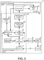
- FIG. 5 is a functional block diagram of a temperature adjustment system including a temperature adjustment device according to a second embodiment of the disclosure.
- the order of calculations of the variation rate and the average value differs from that of the first embodiment.
- the second embodiment is similar to the first embodiment in other respects and descriptions of the similar parts are omitted.
- a temperature adjustment device 10A includes the target value setting part 11, the PID calculation part 12, the input part 13, the PID control part 14, a variation rate calculation part 15A, an average value calculation part 16A, the determination part 17, and the notification part 18.
- the temperature adjustment device 10A is a component of a temperature adjustment system 1A.
- the temperature adjustment system 1A includes the temperature adjustment device 10A, the operator 20, the target device 30, and the sensor 40.
- the host device 50 connected to the temperature adjustment device 10A includes the setting part 51 and the display part 52.
- the average value calculation part 16A calculates an average value of the calculated proportional band P.
- the average value calculation part 16A outputs the calculated average value to the variation rate calculation part 15A.
- the variation rate calculation part 15A calculates a variation rate using the calculated average value of the proportional band P and a reference proportional band P.
- the variation rate calculation part 15A outputs the calculated variation rate to the setting part 51.
- the setting part 51 obtains the variation rate calculated by the variation rate calculation part 15A.
- the setting part 51 calculates a threshold value using the variation rate.
- the setting part 51 outputs the threshold value of the proportional band P to the determination part 17.
- the determination part 17 obtains the threshold value from the setting part 51.
- the determination part 17 calculates a difference between an initial value and a current value of a PID value. When the determination part 17 detects that the difference is greater than the threshold value, the determination part 17 notifies the notification part 18 that updating the PID value is required.
- FIG. 6 is a functional block diagram of a temperature adjustment system including a temperature adjustment device according to a third embodiment of the disclosure.
- the third embodiment is different from the first embodiment in that a temperature adjustment device 10B includes a setting part 51B and a display part 52B.
- the third embodiment is similar to the first embodiment in other respects and descriptions of the similar parts are omitted.
- the temperature adjustment device 10B includes the target value setting part 11, the PID calculation part 12, the input part 13, the PID control part 14, the variation rate calculation part 15, the average value calculation part 16, the determination part 17, the notification part 18, and further includes the setting part 51B and the display part 52B.
- the setting part 51B and the display part 52B are included in the temperature adjustment device 10B such that a seamless temperature adjustment system 1B is constructed. Also, since a device for connecting to the host device can be omitted, space can be saved.
Landscapes
- Engineering & Computer Science (AREA)
- Health & Medical Sciences (AREA)
- Artificial Intelligence (AREA)
- Computer Vision & Pattern Recognition (AREA)
- Evolutionary Computation (AREA)
- Medical Informatics (AREA)
- Software Systems (AREA)
- Physics & Mathematics (AREA)
- General Physics & Mathematics (AREA)
- Automation & Control Theory (AREA)
- Feedback Control In General (AREA)
Abstract

Description
- The disclosure relates to control technology such as temperature control, motor control, etc. for a target device.
- Conventionally, proportional-integral-derivative (PID) control as shown in
Patent Document 1 has been frequently used in control equipment such as a temperature adjuster. - As shown in
Patent Document 1, a PID control device includes a PID control part and a PID adjustment part. The PID adjustment part calculates a PID value (a proportional band P, an integration time TI, a differential time Td, etc.) using adaptive control or auto-tuning and provides the PID value to the PID control part. - The PID control part uses the PID value, a target value of the PID control, and a current value to determine a manipulated variable of a control target.
- The manipulated variable is feedbacked to the PID adjustment part. The PID adjustment part recalculates and updates the PID value using the manipulated variable and provides the PID value to the PID control part.
- [Patent Document 1] Japanese Laid-Open No.
2005-284828 - However, in conventional PID control as described in
Patent Document 1, control performance of the PID control may degrade due to abnormality of a PID value, etc. - Therefore, the purpose of the disclosure is to suppress degradation of control performance of the PID control.
- A control system of the disclosure includes a PID calculation part for calculating a PID value; a PID control part for executing PID control and calculating a manipulated variable of a control target using the PID value, a target value of the control target, and an actual measurement value of the control target; a determination part for notifying a notification part of a change in the PID value if the change is equal to or greater than a threshold value; and a setting part for setting the threshold value using a difference between a past value of the PID value and a current value of the PID value.
- Under this configuration, the threshold value for abnormality detection of the PID control is calculated using each value used for the PID control.
- Also, in the control system of the disclosure, a variation rate calculation part for calculating a variation rate of the PID value is provided, and the threshold value is calculated using the variation rate.
- Under this configuration, the threshold value can be calculated from the variation rate of the PID value, and the threshold value more appropriate for the situation is calculated.
- Furthermore, the variation rate in the control system of the disclosure may be calculated from a difference between a reference value of the PID value and the current value of the PID value.
- Under this configuration, the threshold value can be set according to the system using the actual measurement value of the PID value.
- In addition, the control system of the disclosure may be provided with an average value calculation part for calculating an average value of variation rate, and the average value may be used to calculate the threshold value.
- Under this configuration, a more stable variation rate can be calculated.
- Also, the determination part in the control system of the disclosure calculates a difference between an initial value and the current value of the PID value when the PID value is used. When detecting that the difference is greater than the threshold value, the determination part notifies the notification part of the change.
- Under this configuration, abnormality of the PID control is detected from an amount of change of the PID value.
- According to the disclosure, degradation of control performance of the PID control can be suppressed.
-
-
FIG. 1 is a functional block diagram of a temperature adjustment system including a temperature adjustment device according to a first embodiment of the disclosure. -
FIG. 2 is a flowchart showing a method of determining whether to notify a notification part of the disclosure. -
FIG. 3 is a flowchart showing a method of calculating a threshold value of the PID value of the disclosure. -
FIG. 4 is a table showing a calculation result of the threshold value of the PID value of the disclosure. -
FIG. 5 is a functional block diagram of a temperature adjustment system including a temperature adjustment device according to a second embodiment of the disclosure. -
FIG. 6 is a functional block diagram of a temperature adjustment system including a temperature adjustment device according to a third embodiment of the disclosure. - Embodiments of the disclosure are described below with reference to the drawings.
- First, with reference to
FIG. 1 , an embodiment in which the disclosure is applied will be described.FIG. 1 is a functional block diagram of a temperature adjustment system including a temperature adjustment device according to a first embodiment of the disclosure. - As shown in
FIG. 1 , atemperature adjustment device 10 includes a targetvalue setting part 11, aPID calculation part 12, aninput part 13, aPID control part 14, a variationrate calculation part 15, an averagevalue calculation part 16, adetermination part 17, and anotification part 18. - Also, the
temperature adjustment device 10 is a component of atemperature adjustment system 1. Thetemperature adjustment system 1 includes thetemperature adjustment device 10, anoperator 20, atarget device 30, asensor 40, and ahost device 50. Thehost device 50 connected to thetemperature adjustment device 10 includes asetting part 51 and adisplay part 52. Thetarget device 30 includes, for example, a heater (not shown). Measurement data SS is inputted to theinput part 13 of thetemperature adjustment device 10. Therefore, in this case, the control target is a temperature of thetarget device 30 at a predetermined position. - The
operator 20 is, for example, a solid state relay (SSR), an electromagnetic switch, or a power regulator. Theoperator 20 operates according to a manipulated variable MV from thetemperature adjustment device 10 and controls the power of the heater of thetarget device 30. Thesensor 40 consists of, for example, a thermocouple, etc., measures the temperature of thetarget device 30, and outputs the measurement data SS. Thetemperature adjustment system 1 corresponds to the "control system" of the disclosure. - The
input part 13 calculates an actual measurement value PV from the measurement data SS. The actual measurement value PV is a value having the same unit as a target value SP to be described later. For example, if the target value SP is in degrees Celsius (°C), the actual measurement value PV is also in degrees Celsius (°C). - The
input part 13 outputs the calculated actual measurement value PV to thePID control part 14 and thedetermination part 17. - The target
value setting part 11 sets the target value SP. The target value SP is set by an operator, etc. Also, the targetvalue setting part 11 can use the stored target value SP if including a storage means of the target value SP. The target value SP is, for example, temperature. The targetvalue setting part 11 outputs the target value SP to thePID control part 14. - The
PID calculation part 12 performs auto-tuning such as a limit cycle method and sets a PID value from temperature waveform information. The PID value includes a proportional band P, an integration time TI, and a differential time Td. Specifically, thePID calculation part 12 calculates a dead time L from a limit cycle period Tc. ThePID calculation part 12 calculates the integration time TI and the differential time Td from the dead time L. Also, thePID calculation part 12 calculates the proportional band P from an amplitude of a limit cycle. - The
PID calculation part 12 calculates the PID value by adaptive control using the manipulated variable MV. ThePID calculation part 12 provides the calculated PID value to thePID control part 14. Also, thePID calculation part 12 outputs the proportional band P to the variationrate calculation part 15. - The
PID control part 14 calculates the manipulated variable MV by executing a known PID control operation using the PID value, the target value SP, and the actual measurement value PV. ThePID control part 14 outputs the manipulated variable MV to theoperator 20. - Also, the
PID control part 14 is constituted by a digital filter. Therefore, more specifically, the target value SP and the actual measurement value PV are inputted to thePID control part 14 by an analog/digital (A/D) conversion part (not shown), and the manipulated variable MV is outputted to theoperator 20 by a digital/analog (D/A) conversion part (not shown). - The variation
rate calculation part 15 calculates a variation rate using the proportional band P from thePID calculation part 12 and a reference proportional band P. The variationrate calculation part 15 outputs the calculated variation rate to the averagevalue calculation part 16. - The average
value calculation part 16 performs a product-sum operation on the variation rate calculated by the variationrate calculation part 15 and calculates an average value. The averagevalue calculation part 16 outputs the calculated average value to the settingpart 51. - The setting
part 51 obtains the average value calculated by the averagevalue calculation part 16. The settingpart 51 calculates a threshold value using the average value of the variation rate. The settingpart 51 outputs the threshold value of the proportional band P to thedetermination part 17. - The
determination part 17 obtains the threshold value from the settingpart 51. Thedetermination part 17 calculates a difference between an initial value and a current value of the PID value. Thedetermination part 17 compares the difference with the threshold value and outputs the result to thenotification part 18. - The
notification part 18 may display an alarm by an LED, etc., based on the result received from thedetermination part 17. Thenotification part 18 may output the result to thedisplay part 52. Also, when thetemperature adjustment system 1 is connected to a host system, thetemperature adjustment system 1 may have a function of notifying the result by voltage, etc. - Under this configuration, a statistical threshold value based on the PID value calculated based on the actual measurement value can be calculated and the state of the PID control can be accurately determined. Also, when the PID control is in an abnormal state, the user is prompted to update the PID value. As a result, control degradation due to abnormality of the PID control can be suppressed.
- Next, a temperature adjustment system including a temperature adjustment device according to a first embodiment of the disclosure will be described with reference to the drawings. As mentioned above,
FIG. 1 is a functional block diagram of a temperature adjustment system including a temperature adjustment device according to a first embodiment of the disclosure.FIG. 2 is a flowchart showing a method of determining whether to notify a notification part of the disclosure.FIG. 3 is a flowchart showing a method of calculating a threshold value of the PID value of the disclosure.FIG. 4 is a table showing a calculation result of the threshold value of the PID value of the disclosure. - As mentioned above, in the temperature adjustment system including the temperature adjustment device according to the present embodiment, the presence or absence of an update on the PID value is determined using the threshold value. A determination method is realized by, for example, the flowchart shown in
FIG. 2 . - As shown in
FIG. 2 , thedetermination part 17 obtains a present PID value (a proportional band P) from the PID calculation part 12 (S101). In addition, thedetermination part 17 obtains a threshold value for the proportional band P from the settingpart 51. The method of setting the threshold value in the settingpart 51 will be described later. - The
determination part 17 calculates a difference between the present PID value and a reference PID value (S102). When thedetermination part 17 detects that the difference is equal to or greater than the threshold value Thp (S103: YES), thedetermination part 17 notifies thenotification part 18 of a notification prompting an update on the PID value (S104). - More specifically, a method of calculating the threshold value will be described based on the flowchart of
FIG. 3 . - The
PID calculation part 12 calculates the PID value (S111). The variationrate calculation part 15 sets a proportional band P as a preset reference, compares it with the present proportional band P, and calculates the variation rate (S112). - The average
value calculation part 16 calculates an average value by performing a product-sum operation on the present variation rate obtained from thevariation calculation part 15 and the variation rate calculated up to the previous time (S113). Also, when obtaining the average value for the first time, the variation rate obtained in Step S113 is set as the average value. Furthermore, Step S111, Step S112, and Step S113 may be repeatedly calculated multiple times (m times). - The setting
part 51 calculates the threshold value based on the average value (variation average deviation) obtained from the average value calculation part 16 (S114). As such, the user may update the threshold value by adding an arbitrary value. - The setting
part 51 feedbacks the threshold value to the determination part 17 (S115). - As a result, the
determination part 17 can set the threshold value according to the actual environment based on the threshold value calculated based on a statistical result. - The
display part 52 displays the threshold value set in the settingpart 51. - In
FIG. 4 , the calculation result of the variation rate in Step S112 ofFIG. 3 is shown using more concrete numerical values. - A variation average deviation Scad[n] is calculated using the following equation, wherein n is the number of calculations of the proportional band P executed, Pbfs is the reference proportional band P, and Pbf[n] is the current proportional band P.
- When the number n of calculations of the proportional band P executed is set to the present time and a number "n-1"of calculations of the proportional band P executed at the preceding time is set to the previous time. The variation average deviation Scad[n] between the n-th time and the (n-1)-th time is calculated using the following equation.
- Also, in the equation, the user may set weighting coefficients α and β for the n-th time and the (n-1)-th time respectively. By setting the weighting coefficients α and β, it is possible to select whether to emphasize the previous variation value or to emphasize the current variation value.

- Also, when the variation average deviation Scad[n-1] of the (n-1)-th time is 0, the following equation is used for calculation.

- As an example, "100" is substituted for the reference proportional band P Pbfs and "200" is substituted for Pbf[n] in the above equation. As a result, the present deviation is 100. Also, the following calculation results are calculated without setting the weighting coefficients α and β.
- First, when n = 1, Scad[1] = 50.05 is obtained by substituting the previous average of 0.1 and the above values into
Equation 1, and calculating the present average. - Next, Scad[2] is calculated. Scad[2] = 75.025 is obtained by substituting the value of Scad[1] of the previous time (n = 1) into the previous average of Scad[2].
- On the premise that the deviation changes stepwise, the value of n is incremented by 1 at a time. When the value of n is 7, Scad[7] = 99.21953 and a relative deviation is 1% or less.
- From such, when the number n of calculations of the proportional band P executed is equal to or greater than 7, a variation of the relative deviation of Scad[n] decreases. As such, the threshold value is calculated using the value of Scad[7].
- In addition, the user updates the threshold value by adding an arbitrary value X (%) to the variation average deviation Scad[7] using a ladder, etc., as the host system. For example, by substituting Scad[7] = 99.21953 and X = 3 into the equation of the threshold value (%) = Scad[7] + X, the threshold value (%) becomes "102.21953". By feedbacking this value to the
determination part 17, a more detailed threshold value can be set. - Under this configuration, a statistical threshold value based on the actual measurement value can be calculated and the state of the PID control can be accurately determined.
- That is, when the PID control is in the abnormal state, the user is prompted to update the PID value. As a result, control degradation due to abnormality of the PID control can be suppressed.
- In the above description, an example of calculating the threshold value for the proportional band P of the PID value has been described. However, the threshold value for an integration time may also be calculated.
- Next, a temperature adjustment system including a temperature adjustment device according to a second embodiment of the disclosure will be described with reference to the drawings. As mentioned above,
FIG. 5 is a functional block diagram of a temperature adjustment system including a temperature adjustment device according to a second embodiment of the disclosure. - In the second embodiment, the order of calculations of the variation rate and the average value differs from that of the first embodiment. The second embodiment is similar to the first embodiment in other respects and descriptions of the similar parts are omitted.
- As shown in
FIG. 5 , atemperature adjustment device 10A includes the targetvalue setting part 11, thePID calculation part 12, theinput part 13, thePID control part 14, a variationrate calculation part 15A, an averagevalue calculation part 16A, thedetermination part 17, and thenotification part 18. - Also, the
temperature adjustment device 10A is a component of atemperature adjustment system 1A. Thetemperature adjustment system 1A includes thetemperature adjustment device 10A, theoperator 20, thetarget device 30, and thesensor 40. Thehost device 50 connected to thetemperature adjustment device 10A includes the settingpart 51 and thedisplay part 52. - The average
value calculation part 16A calculates an average value of the calculated proportional band P. The averagevalue calculation part 16A outputs the calculated average value to the variationrate calculation part 15A. - The variation
rate calculation part 15A calculates a variation rate using the calculated average value of the proportional band P and a reference proportional band P. The variationrate calculation part 15A outputs the calculated variation rate to the settingpart 51. - The setting
part 51 obtains the variation rate calculated by the variationrate calculation part 15A. The settingpart 51 calculates a threshold value using the variation rate. The settingpart 51 outputs the threshold value of the proportional band P to thedetermination part 17. - The
determination part 17 obtains the threshold value from the settingpart 51. Thedetermination part 17 calculates a difference between an initial value and a current value of a PID value. When thedetermination part 17 detects that the difference is greater than the threshold value, thedetermination part 17 notifies thenotification part 18 that updating the PID value is required. - Even under this configuration, a statistical threshold value based on the actual measurement value can be calculated and the state of the PID control can be accurately determined.
- When the PID control is in the abnormal state, the user is prompted to update the PID value. As a result, control degradation due to abnormality of the PID control can be suppressed.
- Next, a temperature adjustment system including a temperature adjustment device according to a third embodiment of the disclosure will be described with reference to the drawings. As mentioned above,
FIG. 6 is a functional block diagram of a temperature adjustment system including a temperature adjustment device according to a third embodiment of the disclosure. - The third embodiment is different from the first embodiment in that a
temperature adjustment device 10B includes a settingpart 51B and adisplay part 52B. The third embodiment is similar to the first embodiment in other respects and descriptions of the similar parts are omitted. - As shown in
FIG. 6 , thetemperature adjustment device 10B includes the targetvalue setting part 11, thePID calculation part 12, theinput part 13, thePID control part 14, the variationrate calculation part 15, the averagevalue calculation part 16, thedetermination part 17, thenotification part 18, and further includes the settingpart 51B and thedisplay part 52B. - The setting
part 51B and thedisplay part 52B are included in thetemperature adjustment device 10B such that a seamlesstemperature adjustment system 1B is constructed. Also, since a device for connecting to the host device can be omitted, space can be saved. - Even under this configuration, a statistical threshold value based on the actual measurement value can be calculated and the state of the PID control can be accurately determined.
-
- L: time
- MV: manipulated variable
- n: number of calculations of the proportional band executed
- Pbfs: proportional band
- PV: actual measurement value
- SP: target value
- SS: measurement data
- Tc: limit cycle period
- Td: differential time
- TI: integration time
- 1, 1A, 1B: temperature adjustment system
- 10, 10A, 10B: temperature adjustment device
- 11: target value setting part
- 12: PID calculation part
- 13: input part
- 14: PID control part
- 15, 15A: variation rate calculation part
- 16, 16A: average value calculation part
- 17: determination part
- 18: notification part
- 20: operator
- 30: target device
- 40: sensor
- 50: host device
- 51, 51B: setting part
- 52, 52B: display part
Claims (9)
- A control system (1, 1A, 1B), characterized by comprising
a PID calculation part (12) for calculating a PID value (P, TI, Td);
a PID control part (14) for executing PID control and calculating a manipulated variable (MV) for a control target (30) using the PID value (P, TI, Td), a target value (SP) of the control target (30), and an actual measurement value (PV) of the control target (30);
a determination part (17) for determining whether to notify a notification part (18) by using a threshold value (Thp) of the PID value (P, TI, Td); and
a setting part (51, 51B) for setting the threshold value (Thp) using a difference between a past value of the PID value (P, TI, Td) and a current value of the PID value (P, TI, Td). - The control system (1, 1A, 1B) according to claim 1, comprising
a variation rate calculation part (15, 15A) for calculating a variation rate of the PID value (P, TI, Td), wherein
the threshold value (Thp) is calculated using the variation rate. - The control system (1, 1A, 1B) according to claim 2, wherein
the variation rate is a difference between a reference value (Pbfs) of the PID value (P, TI, Td) and the current value of the PID value (P, TI, Td). - The control system (1, 1A, 1B) according to claim 3, comprising
an average value calculating part (16, 16A) for calculating an average value of the variation rate, wherein
the threshold value (Thp) is calculated using the average value. - The control system (1, 1A, 1B) according to claim 1, wherein when the PID value (P, TI, Td) is used,
the determination part (17) calculates a difference between an initial value and the current value of the PID value (P, TI, Td) and determines whether to notify the notification part (18) upon detecting that the difference between the initial value and the current value of the PID value (P, TI, Td) is greater than the threshold value (Thp). - The control system (1, 1A, 1B) according to any one of claims 1 to 5, comprising
a display part (52, 52B) for displaying the threshold value (Thp) and receiving a correction of the threshold value (Thp). - The control system (1, 1A, 1B) according to claim 5, comprising
the notification part (18) for, when a detection result that the difference between the initial value and the current value of the PID value (P, TI, Td) is greater than the threshold value (Thp) is obtained, notifying based on the detection result. - A control method, characterized by comprising
calculating a PID value (P, TI, Td);
executing PID control and calculating a manipulated variable (MV) for a control target (30) using the PID value (P, TI, Td), a target value (SP) of the control target (30), and an actual measurement value (PV) of the control target (30);
determining whether to notify a notification part (18) by using a threshold value (Thp) of the PID value (P, TI, Td); and
setting the threshold value (Thp) using a difference between a past value of the PID value (P, TI, Td) and a current value of the PID value (P, TI, Td). - A control program, characterized by enabling a control device (10, 10A, 10B) to execute
a PID calculation process of calculating a PID value (P, TI, Td);
a process of executing PID control and calculating a manipulated variable (MV) for a control target (30) using the PID value (P, TI, Td), a target value (SP) of the control target (30), and an actual measurement value (PV) of the control target (30);
a process of determining whether to notify a notification part (18) by using a threshold value (Thp) of the PID value (P, TI, Td); and
a process of setting the threshold value (Thp) using a difference between a past value of the PID value (P, TI, Td) and a current value of the PID value (P, TI, Td).
Applications Claiming Priority (1)
| Application Number | Priority Date | Filing Date | Title |
|---|---|---|---|
| JP2017248985A JP7069702B2 (en) | 2017-12-26 | 2017-12-26 | Control system, control method, control program |
Publications (1)
| Publication Number | Publication Date |
|---|---|
| EP3506027A1 true EP3506027A1 (en) | 2019-07-03 |
Family
ID=63832302
Family Applications (1)
| Application Number | Title | Priority Date | Filing Date |
|---|---|---|---|
| EP18199553.1A Ceased EP3506027A1 (en) | 2017-12-26 | 2018-10-10 | Control system, control method, and control program |
Country Status (2)
| Country | Link |
|---|---|
| EP (1) | EP3506027A1 (en) |
| JP (1) | JP7069702B2 (en) |
Cited By (2)
| Publication number | Priority date | Publication date | Assignee | Title |
|---|---|---|---|---|
| CN111053437A (en) * | 2019-12-03 | 2020-04-24 | 珠海格力电器股份有限公司 | Silicon controlled rectifier heating control method and device, storage medium and household appliance |
| US12111634B2 (en) | 2020-07-27 | 2024-10-08 | Watlow Electric Manufacturing Company | Systems and methods for using intermediate data to improve system control and diagnostics |
Citations (1)
| Publication number | Priority date | Publication date | Assignee | Title |
|---|---|---|---|---|
| JP2005284828A (en) | 2004-03-30 | 2005-10-13 | Omron Corp | Controller, method for tuning control parameter, program, and recording medium |
Family Cites Families (5)
| Publication number | Priority date | Publication date | Assignee | Title |
|---|---|---|---|---|
| JP2004364396A (en) | 2003-06-04 | 2004-12-24 | Yaskawa Electric Corp | Motor control device and control method |
| JP5373550B2 (en) | 2009-10-26 | 2013-12-18 | アズビル株式会社 | Temperature control apparatus and abnormality determination method |
| JP6192340B2 (en) | 2013-04-08 | 2017-09-06 | 株式会社ミクニ | Valve control device |
| JP6200309B2 (en) | 2013-12-13 | 2017-09-20 | アズビル株式会社 | Valve abnormality detection device and method |
| JP6360388B2 (en) | 2014-08-22 | 2018-07-18 | 旭化成エレクトロニクス株式会社 | Motor device control circuit |
-
2017
- 2017-12-26 JP JP2017248985A patent/JP7069702B2/en active Active
-
2018
- 2018-10-10 EP EP18199553.1A patent/EP3506027A1/en not_active Ceased
Patent Citations (1)
| Publication number | Priority date | Publication date | Assignee | Title |
|---|---|---|---|---|
| JP2005284828A (en) | 2004-03-30 | 2005-10-13 | Omron Corp | Controller, method for tuning control parameter, program, and recording medium |
Non-Patent Citations (3)
| Title |
|---|
| ÉRIC POULIN ET AL: "Development and evaluation of an auto-tuning and adaptive PID controller", AUTOMATICA, vol. 32, no. 1, 1 January 1996 (1996-01-01), AMSTERDAM, NL, pages 71 - 82, XP055588660, ISSN: 0005-1098, DOI: 10.1016/0005-1098(95)00105-0 * |
| IFAC Professional Brief, Hands-on PID autotuning: a guide to better utilisation * |
| JOHN E. SEEM: "A New Pattern Recognition Adaptive Controller with Application to HVAC Systems", AUTOMATICA, vol. 34, no. 8, 1 August 1998 (1998-08-01), AMSTERDAM, NL, pages 969 - 982, XP055588760, ISSN: 0005-1098, DOI: 10.1016/S0005-1098(98)00033-8 * |
Cited By (3)
| Publication number | Priority date | Publication date | Assignee | Title |
|---|---|---|---|---|
| CN111053437A (en) * | 2019-12-03 | 2020-04-24 | 珠海格力电器股份有限公司 | Silicon controlled rectifier heating control method and device, storage medium and household appliance |
| CN111053437B (en) * | 2019-12-03 | 2023-03-14 | 珠海格力电器股份有限公司 | Silicon controlled rectifier heating control method and device, storage medium and household appliance |
| US12111634B2 (en) | 2020-07-27 | 2024-10-08 | Watlow Electric Manufacturing Company | Systems and methods for using intermediate data to improve system control and diagnostics |
Also Published As
| Publication number | Publication date |
|---|---|
| JP2019114178A (en) | 2019-07-11 |
| JP7069702B2 (en) | 2022-05-18 |
Similar Documents
| Publication | Publication Date | Title |
|---|---|---|
| Zarei et al. | Robust sensor fault detection based on nonlinear unknown input observer | |
| Bobal et al. | Adaptive predictive control of time-delay systems | |
| EP2930573B1 (en) | Adjustment device, control method, and control program | |
| KR101478450B1 (en) | Design method of variable pid gains for multivariable nonlinear systems | |
| US20110218782A1 (en) | Rapid process model identification and generation | |
| KR102173653B1 (en) | System state prediction | |
| EP2725434A1 (en) | Feedback control method, feedback control apparatus, and feedback control program | |
| EP3206094B1 (en) | Predicted value modification system, control system, predicted value modification method, control method, and predicted value modification program | |
| Ji et al. | Application of MHE to large-scale nonlinear processes with delayed lab measurements | |
| EP3349084A1 (en) | Process monitoring device and method | |
| JP6874379B2 (en) | Control device, control method, control program | |
| JP7069702B2 (en) | Control system, control method, control program | |
| EP4063975A1 (en) | Rst smith predictor | |
| EP3349074B1 (en) | Control device, control method, and control program for tuning an amount of operation of a device | |
| CN102928014A (en) | Method and device for digital measurement or telemetering processing of electric power system | |
| JP6922224B2 (en) | Control device, control method, control program | |
| JP2016173708A (en) | Control device and control method | |
| Dovhopolyi et al. | Development of the program for selftuning a proportalintegraldifferential controller with an additional controlling action | |
| Balasevicius et al. | Design of the deadbeat controller with limited output | |
| da Silva et al. | Parametric ARX modeling of the electrolytic smelter pot | |
| Juric et al. | An extension of the Ziegler-Nichol's method for parametric identification of standard plants | |
| Vojtesek et al. | Adaptive control of chemical reactor | |
| Vrána et al. | Evaluation of open-loop frequency indicators in a closed loop for PID controller autotuning | |
| Inoue et al. | Model free fault detection using one set of reference input and output data | |
| Hofreiter | Parameter Estimate of Anisochronic Models Using Method of Moments |
Legal Events
| Date | Code | Title | Description |
|---|---|---|---|
| PUAI | Public reference made under article 153(3) epc to a published international application that has entered the european phase |
Free format text: ORIGINAL CODE: 0009012 |
|
| STAA | Information on the status of an ep patent application or granted ep patent |
Free format text: STATUS: REQUEST FOR EXAMINATION WAS MADE |
|
| 17P | Request for examination filed |
Effective date: 20181010 |
|
| AK | Designated contracting states |
Kind code of ref document: A1 Designated state(s): AL AT BE BG CH CY CZ DE DK EE ES FI FR GB GR HR HU IE IS IT LI LT LU LV MC MK MT NL NO PL PT RO RS SE SI SK SM TR |
|
| AX | Request for extension of the european patent |
Extension state: BA ME |
|
| RBV | Designated contracting states (corrected) |
Designated state(s): AL AT BE BG CH CY CZ DE DK EE ES FI FR GB GR HR HU IE IS IT LI LT LU LV MC MK MT NL NO PL PT RO RS SE SI SK SM TR |
|
| STAA | Information on the status of an ep patent application or granted ep patent |
Free format text: STATUS: EXAMINATION IS IN PROGRESS |
|
| 17Q | First examination report despatched |
Effective date: 20210929 |
|
| STAA | Information on the status of an ep patent application or granted ep patent |
Free format text: STATUS: THE APPLICATION HAS BEEN REFUSED |
|
| 18R | Application refused |
Effective date: 20231114 |