EP3505990A1 - Liquid crystal panel, liquid crystal display device, display device, movable body, and light source device - Google Patents
Liquid crystal panel, liquid crystal display device, display device, movable body, and light source device Download PDFInfo
- Publication number
- EP3505990A1 EP3505990A1 EP17846091.1A EP17846091A EP3505990A1 EP 3505990 A1 EP3505990 A1 EP 3505990A1 EP 17846091 A EP17846091 A EP 17846091A EP 3505990 A1 EP3505990 A1 EP 3505990A1
- Authority
- EP
- European Patent Office
- Prior art keywords
- light
- liquid crystal
- face
- light source
- crystal panel
- Prior art date
- Legal status (The legal status is an assumption and is not a legal conclusion. Google has not performed a legal analysis and makes no representation as to the accuracy of the status listed.)
- Granted
Links
Images





Classifications
-
- G—PHYSICS
- G02—OPTICS
- G02B—OPTICAL ELEMENTS, SYSTEMS OR APPARATUS
- G02B27/00—Optical systems or apparatus not provided for by any of the groups G02B1/00 - G02B26/00, G02B30/00
- G02B27/01—Head-up displays
- G02B27/0101—Head-up displays characterised by optical features
-
- B—PERFORMING OPERATIONS; TRANSPORTING
- B60—VEHICLES IN GENERAL
- B60K—ARRANGEMENT OR MOUNTING OF PROPULSION UNITS OR OF TRANSMISSIONS IN VEHICLES; ARRANGEMENT OR MOUNTING OF PLURAL DIVERSE PRIME-MOVERS IN VEHICLES; AUXILIARY DRIVES FOR VEHICLES; INSTRUMENTATION OR DASHBOARDS FOR VEHICLES; ARRANGEMENTS IN CONNECTION WITH COOLING, AIR INTAKE, GAS EXHAUST OR FUEL SUPPLY OF PROPULSION UNITS IN VEHICLES
- B60K35/00—Instruments specially adapted for vehicles; Arrangement of instruments in or on vehicles
- B60K35/20—Output arrangements, i.e. from vehicle to user, associated with vehicle functions or specially adapted therefor
- B60K35/21—Output arrangements, i.e. from vehicle to user, associated with vehicle functions or specially adapted therefor using visual output, e.g. blinking lights or matrix displays
- B60K35/23—Head-up displays [HUD]
-
- B—PERFORMING OPERATIONS; TRANSPORTING
- B60—VEHICLES IN GENERAL
- B60K—ARRANGEMENT OR MOUNTING OF PROPULSION UNITS OR OF TRANSMISSIONS IN VEHICLES; ARRANGEMENT OR MOUNTING OF PLURAL DIVERSE PRIME-MOVERS IN VEHICLES; AUXILIARY DRIVES FOR VEHICLES; INSTRUMENTATION OR DASHBOARDS FOR VEHICLES; ARRANGEMENTS IN CONNECTION WITH COOLING, AIR INTAKE, GAS EXHAUST OR FUEL SUPPLY OF PROPULSION UNITS IN VEHICLES
- B60K35/00—Instruments specially adapted for vehicles; Arrangement of instruments in or on vehicles
- B60K35/60—Instruments characterised by their location or relative disposition in or on vehicles
-
- B—PERFORMING OPERATIONS; TRANSPORTING
- B60—VEHICLES IN GENERAL
- B60K—ARRANGEMENT OR MOUNTING OF PROPULSION UNITS OR OF TRANSMISSIONS IN VEHICLES; ARRANGEMENT OR MOUNTING OF PLURAL DIVERSE PRIME-MOVERS IN VEHICLES; AUXILIARY DRIVES FOR VEHICLES; INSTRUMENTATION OR DASHBOARDS FOR VEHICLES; ARRANGEMENTS IN CONNECTION WITH COOLING, AIR INTAKE, GAS EXHAUST OR FUEL SUPPLY OF PROPULSION UNITS IN VEHICLES
- B60K35/00—Instruments specially adapted for vehicles; Arrangement of instruments in or on vehicles
- B60K35/80—Arrangements for controlling instruments
- B60K35/81—Arrangements for controlling instruments for controlling displays
-
- G—PHYSICS
- G02—OPTICS
- G02B—OPTICAL ELEMENTS, SYSTEMS OR APPARATUS
- G02B27/00—Optical systems or apparatus not provided for by any of the groups G02B1/00 - G02B26/00, G02B30/00
- G02B27/01—Head-up displays
-
- G—PHYSICS
- G02—OPTICS
- G02B—OPTICAL ELEMENTS, SYSTEMS OR APPARATUS
- G02B27/00—Optical systems or apparatus not provided for by any of the groups G02B1/00 - G02B26/00, G02B30/00
- G02B27/28—Optical systems or apparatus not provided for by any of the groups G02B1/00 - G02B26/00, G02B30/00 for polarising
- G02B27/283—Optical systems or apparatus not provided for by any of the groups G02B1/00 - G02B26/00, G02B30/00 for polarising used for beam splitting or combining
-
- G—PHYSICS
- G02—OPTICS
- G02F—OPTICAL DEVICES OR ARRANGEMENTS FOR THE CONTROL OF LIGHT BY MODIFICATION OF THE OPTICAL PROPERTIES OF THE MEDIA OF THE ELEMENTS INVOLVED THEREIN; NON-LINEAR OPTICS; FREQUENCY-CHANGING OF LIGHT; OPTICAL LOGIC ELEMENTS; OPTICAL ANALOGUE/DIGITAL CONVERTERS
- G02F1/00—Devices or arrangements for the control of the intensity, colour, phase, polarisation or direction of light arriving from an independent light source, e.g. switching, gating or modulating; Non-linear optics
- G02F1/01—Devices or arrangements for the control of the intensity, colour, phase, polarisation or direction of light arriving from an independent light source, e.g. switching, gating or modulating; Non-linear optics for the control of the intensity, phase, polarisation or colour
- G02F1/13—Devices or arrangements for the control of the intensity, colour, phase, polarisation or direction of light arriving from an independent light source, e.g. switching, gating or modulating; Non-linear optics for the control of the intensity, phase, polarisation or colour based on liquid crystals, e.g. single liquid crystal display cells
- G02F1/133—Constructional arrangements; Operation of liquid crystal cells; Circuit arrangements
- G02F1/1333—Constructional arrangements; Manufacturing methods
-
- G—PHYSICS
- G02—OPTICS
- G02F—OPTICAL DEVICES OR ARRANGEMENTS FOR THE CONTROL OF LIGHT BY MODIFICATION OF THE OPTICAL PROPERTIES OF THE MEDIA OF THE ELEMENTS INVOLVED THEREIN; NON-LINEAR OPTICS; FREQUENCY-CHANGING OF LIGHT; OPTICAL LOGIC ELEMENTS; OPTICAL ANALOGUE/DIGITAL CONVERTERS
- G02F1/00—Devices or arrangements for the control of the intensity, colour, phase, polarisation or direction of light arriving from an independent light source, e.g. switching, gating or modulating; Non-linear optics
- G02F1/01—Devices or arrangements for the control of the intensity, colour, phase, polarisation or direction of light arriving from an independent light source, e.g. switching, gating or modulating; Non-linear optics for the control of the intensity, phase, polarisation or colour
- G02F1/13—Devices or arrangements for the control of the intensity, colour, phase, polarisation or direction of light arriving from an independent light source, e.g. switching, gating or modulating; Non-linear optics for the control of the intensity, phase, polarisation or colour based on liquid crystals, e.g. single liquid crystal display cells
- G02F1/133—Constructional arrangements; Operation of liquid crystal cells; Circuit arrangements
- G02F1/1333—Constructional arrangements; Manufacturing methods
- G02F1/133302—Rigid substrates, e.g. inorganic substrates
-
- G—PHYSICS
- G02—OPTICS
- G02F—OPTICAL DEVICES OR ARRANGEMENTS FOR THE CONTROL OF LIGHT BY MODIFICATION OF THE OPTICAL PROPERTIES OF THE MEDIA OF THE ELEMENTS INVOLVED THEREIN; NON-LINEAR OPTICS; FREQUENCY-CHANGING OF LIGHT; OPTICAL LOGIC ELEMENTS; OPTICAL ANALOGUE/DIGITAL CONVERTERS
- G02F1/00—Devices or arrangements for the control of the intensity, colour, phase, polarisation or direction of light arriving from an independent light source, e.g. switching, gating or modulating; Non-linear optics
- G02F1/01—Devices or arrangements for the control of the intensity, colour, phase, polarisation or direction of light arriving from an independent light source, e.g. switching, gating or modulating; Non-linear optics for the control of the intensity, phase, polarisation or colour
- G02F1/13—Devices or arrangements for the control of the intensity, colour, phase, polarisation or direction of light arriving from an independent light source, e.g. switching, gating or modulating; Non-linear optics for the control of the intensity, phase, polarisation or colour based on liquid crystals, e.g. single liquid crystal display cells
- G02F1/133—Constructional arrangements; Operation of liquid crystal cells; Circuit arrangements
- G02F1/1333—Constructional arrangements; Manufacturing methods
- G02F1/1335—Structural association of cells with optical devices, e.g. polarisers or reflectors
-
- G—PHYSICS
- G02—OPTICS
- G02F—OPTICAL DEVICES OR ARRANGEMENTS FOR THE CONTROL OF LIGHT BY MODIFICATION OF THE OPTICAL PROPERTIES OF THE MEDIA OF THE ELEMENTS INVOLVED THEREIN; NON-LINEAR OPTICS; FREQUENCY-CHANGING OF LIGHT; OPTICAL LOGIC ELEMENTS; OPTICAL ANALOGUE/DIGITAL CONVERTERS
- G02F1/00—Devices or arrangements for the control of the intensity, colour, phase, polarisation or direction of light arriving from an independent light source, e.g. switching, gating or modulating; Non-linear optics
- G02F1/01—Devices or arrangements for the control of the intensity, colour, phase, polarisation or direction of light arriving from an independent light source, e.g. switching, gating or modulating; Non-linear optics for the control of the intensity, phase, polarisation or colour
- G02F1/13—Devices or arrangements for the control of the intensity, colour, phase, polarisation or direction of light arriving from an independent light source, e.g. switching, gating or modulating; Non-linear optics for the control of the intensity, phase, polarisation or colour based on liquid crystals, e.g. single liquid crystal display cells
- G02F1/133—Constructional arrangements; Operation of liquid crystal cells; Circuit arrangements
- G02F1/1333—Constructional arrangements; Manufacturing methods
- G02F1/1335—Structural association of cells with optical devices, e.g. polarisers or reflectors
- G02F1/1336—Illuminating devices
- G02F1/133602—Direct backlight
- G02F1/133603—Direct backlight with LEDs
-
- G—PHYSICS
- G02—OPTICS
- G02F—OPTICAL DEVICES OR ARRANGEMENTS FOR THE CONTROL OF LIGHT BY MODIFICATION OF THE OPTICAL PROPERTIES OF THE MEDIA OF THE ELEMENTS INVOLVED THEREIN; NON-LINEAR OPTICS; FREQUENCY-CHANGING OF LIGHT; OPTICAL LOGIC ELEMENTS; OPTICAL ANALOGUE/DIGITAL CONVERTERS
- G02F1/00—Devices or arrangements for the control of the intensity, colour, phase, polarisation or direction of light arriving from an independent light source, e.g. switching, gating or modulating; Non-linear optics
- G02F1/01—Devices or arrangements for the control of the intensity, colour, phase, polarisation or direction of light arriving from an independent light source, e.g. switching, gating or modulating; Non-linear optics for the control of the intensity, phase, polarisation or colour
- G02F1/13—Devices or arrangements for the control of the intensity, colour, phase, polarisation or direction of light arriving from an independent light source, e.g. switching, gating or modulating; Non-linear optics for the control of the intensity, phase, polarisation or colour based on liquid crystals, e.g. single liquid crystal display cells
- G02F1/133—Constructional arrangements; Operation of liquid crystal cells; Circuit arrangements
- G02F1/1333—Constructional arrangements; Manufacturing methods
- G02F1/1335—Structural association of cells with optical devices, e.g. polarisers or reflectors
- G02F1/1336—Illuminating devices
- G02F1/133602—Direct backlight
- G02F1/133606—Direct backlight including a specially adapted diffusing, scattering or light controlling members
-
- B—PERFORMING OPERATIONS; TRANSPORTING
- B60—VEHICLES IN GENERAL
- B60K—ARRANGEMENT OR MOUNTING OF PROPULSION UNITS OR OF TRANSMISSIONS IN VEHICLES; ARRANGEMENT OR MOUNTING OF PLURAL DIVERSE PRIME-MOVERS IN VEHICLES; AUXILIARY DRIVES FOR VEHICLES; INSTRUMENTATION OR DASHBOARDS FOR VEHICLES; ARRANGEMENTS IN CONNECTION WITH COOLING, AIR INTAKE, GAS EXHAUST OR FUEL SUPPLY OF PROPULSION UNITS IN VEHICLES
- B60K2360/00—Indexing scheme associated with groups B60K35/00 or B60K37/00 relating to details of instruments or dashboards
- B60K2360/20—Optical features of instruments
- B60K2360/23—Optical features of instruments using reflectors
-
- B—PERFORMING OPERATIONS; TRANSPORTING
- B60—VEHICLES IN GENERAL
- B60K—ARRANGEMENT OR MOUNTING OF PROPULSION UNITS OR OF TRANSMISSIONS IN VEHICLES; ARRANGEMENT OR MOUNTING OF PLURAL DIVERSE PRIME-MOVERS IN VEHICLES; AUXILIARY DRIVES FOR VEHICLES; INSTRUMENTATION OR DASHBOARDS FOR VEHICLES; ARRANGEMENTS IN CONNECTION WITH COOLING, AIR INTAKE, GAS EXHAUST OR FUEL SUPPLY OF PROPULSION UNITS IN VEHICLES
- B60K2360/00—Indexing scheme associated with groups B60K35/00 or B60K37/00 relating to details of instruments or dashboards
- B60K2360/20—Optical features of instruments
- B60K2360/33—Illumination features
- B60K2360/334—Projection means
-
- G—PHYSICS
- G02—OPTICS
- G02B—OPTICAL ELEMENTS, SYSTEMS OR APPARATUS
- G02B27/00—Optical systems or apparatus not provided for by any of the groups G02B1/00 - G02B26/00, G02B30/00
- G02B27/01—Head-up displays
- G02B27/0101—Head-up displays characterised by optical features
- G02B2027/0118—Head-up displays characterised by optical features comprising devices for improving the contrast of the display / brillance control visibility
-
- G—PHYSICS
- G02—OPTICS
- G02F—OPTICAL DEVICES OR ARRANGEMENTS FOR THE CONTROL OF LIGHT BY MODIFICATION OF THE OPTICAL PROPERTIES OF THE MEDIA OF THE ELEMENTS INVOLVED THEREIN; NON-LINEAR OPTICS; FREQUENCY-CHANGING OF LIGHT; OPTICAL LOGIC ELEMENTS; OPTICAL ANALOGUE/DIGITAL CONVERTERS
- G02F1/00—Devices or arrangements for the control of the intensity, colour, phase, polarisation or direction of light arriving from an independent light source, e.g. switching, gating or modulating; Non-linear optics
- G02F1/01—Devices or arrangements for the control of the intensity, colour, phase, polarisation or direction of light arriving from an independent light source, e.g. switching, gating or modulating; Non-linear optics for the control of the intensity, phase, polarisation or colour
- G02F1/13—Devices or arrangements for the control of the intensity, colour, phase, polarisation or direction of light arriving from an independent light source, e.g. switching, gating or modulating; Non-linear optics for the control of the intensity, phase, polarisation or colour based on liquid crystals, e.g. single liquid crystal display cells
- G02F1/133—Constructional arrangements; Operation of liquid crystal cells; Circuit arrangements
- G02F1/1333—Constructional arrangements; Manufacturing methods
- G02F1/1335—Structural association of cells with optical devices, e.g. polarisers or reflectors
- G02F1/1336—Illuminating devices
- G02F1/133602—Direct backlight
- G02F1/133606—Direct backlight including a specially adapted diffusing, scattering or light controlling members
- G02F1/133607—Direct backlight including a specially adapted diffusing, scattering or light controlling members the light controlling member including light directing or refracting elements, e.g. prisms or lenses
Definitions
- This disclosure relates to a liquid crystal panel, a liquid crystal display apparatus, a display apparatus, a moving body and a light source apparatus.
- Patent Literature 1 discloses a technique to control the light intensity of a light source depending on the ambient brightness.
- a liquid crystal panel includes a first transmissive member, a liquid crystal layer and a second transmissive member.
- the first transmissive member has a first face. Light enters the first face.
- the second transmissive member has a second face. At least a part of the light having passed through the first transmissive member and the liquid crystal layer exits the second face. The second face is inclined relative to the liquid crystal layer.
- a liquid crystal panel includes a first transmissive member, a liquid crystal layer and a second transmissive member.
- the first transmissive member has a first face. Light enters the first face.
- the second transmissive member has a second face. At least a part of the light having passed through the first transmissive member and the liquid crystal layer exits the second face. At least a part of the light having passed approximately vertically through the liquid crystal layer is refracted at and exits the second face.
- a liquid crystal display apparatus includes a light source element and a liquid crystal panel.
- the light source element emits light.
- the liquid crystal panel is located in the direction along which the light emitted from the light source element travels.
- the liquid crystal panel includes a first transmissive member, a liquid crystal layer and a second transmissive member.
- the first transmissive member has a first face. Light from the light source element enters the first face.
- the second transmissive member has a second face. At least a part of the light having passed through the first transmissive member and the liquid crystal layer exits the second face. The second face is inclined relative to the liquid crystal layer.
- a liquid crystal display apparatus includes a light source element and a liquid crystal panel.
- the light source element emits light.
- the liquid crystal panel is located in the direction along which the light emitted from the light source element travels.
- the liquid crystal panel includes a first transmissive member, a liquid crystal layer and a second transmissive member.
- the first transmissive member has a first face. Light from the light source element enters the first face.
- the second transmissive member has a second face. At least a part of the light having passed through the first transmissive member and the liquid crystal layer exits the second face. At least a part of the light having passed approximately vertically through the liquid crystal layer is refracted at and exits the second face.
- a display apparatus includes a light source element, a liquid crystal panel and one or more optical members.
- the light source element emits light.
- the liquid crystal panel is located in the direction along which the light emitted from the light source element travels.
- the liquid crystal panel has a first transmissive member, a liquid crystal layer and a second transmissive member.
- the first transmissive member has a first face. Light from the light source element enters the first face.
- the second transmissive member has a second face. At least a part of the light having passed through the first transmissive member and the liquid crystal layer exits the second face.
- the one or more optical members allow the light having exited the second face to reach a predetermined region in a real space.
- the second face is inclined relative to the liquid crystal layer.
- a display apparatus includes a light source element, a liquid crystal panel and one or more optical members.
- the light source element emits light.
- the liquid crystal panel is located in the direction along which the light emitted from the light source element travels.
- the liquid crystal panel includes a first transmissive member, a liquid crystal layer and a second transmissive member.
- the first transmissive member has a first face. Light from the light source element enters the first face.
- the second transmissive member has a second face. At least a part of the light having passed through the first transmissive member and the liquid crystal layer exits the second face.
- the one or more optical members allow the light having exited the second face to reach a predetermined region in a real space. At least a part of the light having passed approximately vertically through the liquid crystal layer is refracted at and exits the second face.
- a moving body includes a light source element, a liquid crystal panel and one or more optical members.
- the light source element emits light.
- the liquid crystal panel is located in the direction along which the light emitted from the light source element travels.
- the liquid crystal panel includes a first transmissive member, a liquid crystal layer and a second transmissive member.
- the first transmissive member has a first face. Light from the light source element enters the first face.
- the second transmissive member has a second face. At least a part of the light having passed through the first transmissive member and the liquid crystal layer exits the second face.
- the one or more optical members allow the light having exited the second face to reach a predetermined region in a real space.
- the second face is inclined relative to the liquid crystal layer.
- a moving body includes a light source element, a liquid crystal panel and one or more optical members.
- the light source element emits light.
- the liquid crystal panel is located in the direction along which the light emitted from the light source element travels.
- the liquid crystal panel includes a first transmissive member, a liquid crystal layer and a second transmissive member.
- the first transmissive member has a first face. Light from the light source element enters the first face.
- the second transmissive member has a second face. At least a part of the light having passed through the first transmissive member and the liquid crystal layer exits the second face.
- the one or more optical members allow the light having exited the second face to reach a predetermined region in a real space. At least a part of the light having passed approximately vertically through the liquid crystal layer is refracted at and exits the second face.
- a light source apparatus includes a light source element, a liquid crystal panel, a beam splitter and a light guiding member.
- the light source element emits light.
- the liquid crystal panel is located in the progressive direction in a light path of the light emitted from the light source element.
- the beam splitter is located in the progressive direction of the liquid crystal panel.
- the beam splitter is inclined relative to a plane vertical to the progressive direction.
- the liquid crystal panel has a first face and a second face. Light from the light source element enters the first face. Image projection light resulting from polarization of the light having entered the first face in a predetermined polarization direction exits the second face.
- the beam splitter allows the image projection light having exited the second face of the liquid crystal panel and traveling in the progressive direction to pass through and also reflects external light traveling in the retrograde direction opposite to the progressive direction in the direction different from the progressive direction.
- the light guiding member guides and allows the external light reflected by the beam splitter to enter the first face of the liquid crystal panel.
- a display apparatus allows a user to visually recognize a virtual image of an image.
- the display apparatus includes a light source element, a liquid crystal panel, a beam splitter, one or more optical members and a light guiding member.
- the light source element emits light.
- the liquid crystal panel is located in the progressive direction in a light path of the light emitted from the light source element.
- the beam splitter is located in the progressive direction of the liquid crystal panel.
- the beam splitter is inclined relative to a plane vertical to the progressive direction.
- the liquid crystal panel has a first face and a second face. Light from the light source element enters the first face. Image projection light resulting from polarization of the light having entered the first face in a predetermined polarization direction exits the second face.
- the beam splitter allows the image projection light having exited the second face of the liquid crystal panel and traveling in the progressive direction to pass through and reflects external light traveling in the retrograde direction opposite to the progressive direction in the direction different from the progressive direction.
- the one or more optical members allow the image projection light having passed through the beam splitter to reach a predetermined region in a real space.
- the light guiding member guides and allows the external light reflected by the beam splitter to enter the first face of the liquid crystal panel.
- a moving body allows a user to visually recognize a virtual image of an image.
- the moving body includes a light source element, a liquid crystal panel, a beam splitter, one or more optical members and a light guiding member.
- the light source element emits light.
- the liquid crystal panel is located in the progressive direction in a light path of the light emitted from the light source element.
- the beam splitter is located in the progressive direction of the liquid crystal panel.
- the beam splitter is inclined relative to a plane vertical to the progressive direction.
- the liquid crystal panel has a first face and a second face. Light from the light source element enters the first face. Image projection light resulting from polarization of the light having entered the first face in a predetermined polarization direction exits the second face.
- the beam splitter allows the image projection light having exited the second face of the liquid crystal panel and traveling in the progressive direction to pass through and reflects external light traveling in the retrograde direction opposite to the progressive direction in the direction different from the progressive direction.
- the one or more optical members allow the image projection light having passed through the beam splitter to reach a predetermined region in a real space.
- the light guiding member guides and allows the external light reflected by the beam splitter to enter the first face of the liquid crystal panel.
- a moving body 10 and a display apparatus 11 according to Embodiment 1 will be described with reference to FIG. 1 .
- the moving body 10 is provided with a display apparatus 11.
- the moving body 10 may include, for example, vehicles, ships, aircrafts and the like.
- Vehicles may include, for example, automobiles, industrial vehicles, rail vehicles, campers, fixed-wing airplanes running on runway, and the like.
- Automobiles may include, for example, passenger cars, trucks, buses, two-wheel vehicles, trolleybuses and the like.
- Industrial vehicles may include, for example, agricultural and construction industrial vehicles and the like.
- Industrial vehicles may include, for example, forklifts, golf carts and the like.
- Agricultural industrial vehicles may include, for example, tractors, tillers, transplanters, binders, combines, lawn mowers and the like.
- Construction industrial vehicles may include, for example, bulldozers, scrapers, loading shovels, crane vehicles, dump trucks, road rollers and the like.
- Vehicles may include human-powered vehicles. Vehicle classification is not limited to the above described examples. For example, automobiles may include industrial vehicles that can travel on the road. Same vehicle may be included in some categories. Ships may include, for example, jet ski bikes, boats, tankers and the like. Aircrafts may include, for example, fixed-wing airplanes, rotor-wing airplanes and the like.
- the display apparatus 11 may be disposed at any positions in the moving body 10.
- the display apparatus 11 may be disposed in a dashboard of the moving body 10, for example.
- the display apparatus 11 serves as a part of a head-up display that allows a user 12 such as a driver of the moving body 10, for example, to visually recognize a virtual image 13 of a desired image. More specifically, in an embodiment, the display apparatus 11 emits image projection light toward a predetermined region of a first optical member 14 provided in the moving body 10.
- the first optical member 14 may be a windshield.
- the first optical member 14 may be a combiner.
- the display apparatus 11 serves as a head-up display. Details of the image projection light will be described later.
- the image projection light reflected by a predetermined region of the first optical member 14 arrives at an eye box 15.
- the eye box 15 is a region in a real space where eyes of the user 12 are supposed to be present in light of a build, a posture, a change in the posture and the like of the user 12, for example.
- the solid arrow in FIG. 1 illustrates a path along which a part of the image projection light emitted from the display apparatus 11 arrives at the eye box 15.
- a path along which the light travels is also referred to as a light path.
- the user 12 can visually recognize a virtual image 13 of an image by the image projection light arrived at the eye box 15.
- the virtual image 13 can be visually recognized in front of the moving body 10, for example.
- the display apparatus 11, in cooperation with the first optical member 14, allows the user 12 such as a driver of the moving body 10 to visually recognize the virtual image 13 of the desired image.
- external light such as sunlight and the like may pass through the first optical member 14 and enter the display apparatus 11 along a path in the direction opposite to the path along which the image projection light travels.
- the dashed arrow in FIG. 1 illustrates a path of the external light entering the display apparatus 11. Details of the external light entering the display apparatus 11 will be described later.
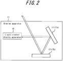
- the display apparatus 11 includes a liquid crystal display apparatus 16 and one or more second optical members 17.
- FIG. 2 illustrates a configuration in which the display apparatus 11 includes two second optical members 17a and 17b.
- FIG. 2 schematically illustrates an example of configuration of the display apparatus 11.
- the size, the shape and the arrangement and the like of the display apparatus 11 and each component of the display apparatus 11 are not limited to the example illustrated in FIG. 2 .
- the liquid crystal display apparatus 16 emits image projection light in the display apparatus 11.
- the detailed configuration of the liquid crystal display apparatus 16 will be described later.
- the second optical member 17 allows the image projection light emitted from the liquid crystal display apparatus 16 to arrive at the outside of the display apparatus 11.
- the second optical members 17a and 17b allow the image projection light emitted from the liquid crystal display apparatus 16 to arrive at the outside of the display apparatus 11.
- at least one of the second optical members 17a and 17b may be a mirror.
- the solid arrow in FIG. 2 illustrates a path indicating that a part of the image projection light emitted from the liquid crystal display apparatus 16 is reflected by the second optical members 17a and 17b, passes through a window provided in a housing of the display apparatus 11 and arrives at the outside of the display apparatus 11.
- the image projection light arrived at the outside of the display apparatus 11 arrives at a predetermined region of the first optical member 14 provided in the moving body 10, as illustrated in FIG. 1 .
- at least one of the second optical members 17a and 17b may be a lens.
- one of the second optical members 17a and 17b may be a mirror and the other may be a lens.
- the second optical members 17a and 17b may serve as an expansion optical system that expands the image projection light.
- at least one of the second optical members 17a and 17b may be a mirror having a convex or concave shape at least a part on the face where the image projection light arrives at.
- at least one of the second optical members 17a and 17b may be a lens having a convex or concave shape at least a part on the face where the image projection light enters or exits. At least a part of the convex shape and the concave shape may be sphere or non-sphere.
- the external light having entered the display apparatus 11 may, in the display apparatus 11, enter the liquid crystal display apparatus 16 by a path opposite to the path along which the image projection light travels.
- the dashed arrow in FIG. 2 illustrates a path of the external light that enters the liquid crystal display apparatus 16. The external light entering the liquid crystal display apparatus 16 will be described in detail later.
- the liquid crystal display apparatus 16 includes a substrate 18, a light source element 19, a third optical member 20, a fourth optical member 21, a liquid crystal panel 22 and a controller 23.
- the substrate 18, the light source element 19, the third optical member 20 and the fourth optical member 21 may be configured as one light source apparatus 31.
- the liquid crystal display apparatus 16 may include the liquid crystal panel 22 and the controller 23.
- the substrate 18, the third optical member 20, the fourth optical member 21 and the liquid crystal panel 22 may be fixedly disposed in the liquid crystal display apparatus 16.
- the light source element 19 may be disposed on the substrate 18.
- FIG. 3 schematically illustrates an example of a configuration of the liquid crystal display apparatus 16.
- the size, the shape and the arrangement and the like of the liquid crystal display apparatus 16 and each component of the liquid crystal display apparatus 16 are not limited to the example illustrated in FIG. 3 .
- the light source element 19 includes one or more Light Emitting Diodes (LED) or a laser apparatus and the like.
- the light source element 19 may emit light according to the control of the controller 23.
- the light source element 19 may include a plurality of light emitting diodes, the colors of lights emitted from respective diodes being different from each other.
- the solid arrow extending from the light source element 19 schematically illustrates a path along which a part of the light emitted from the light source element 19 travels.
- at least a part of the light emitted from the light source element 19 is also referred to merely as the light from the light source element 19.
- the light path of the light passing through the liquid crystal panel 22 is schematically illustrated. The details of the light path of the light passing through the liquid crystal panel 22 will be described later.
- the third optical member 20 is located, with respect to the position of the light source element 19, in the direction along which the light from the light source element 19 travels.
- the third optical member 20 is located to the right of the light source element 19.
- the third optical member 20 includes a collimator lens, for example.
- the third optical member 20 collimates light entering from the light source element 19.
- the collimated light may be the light traveling in approximately parallel to the optical axial direction of the third optical member 20.
- the fourth optical member 21 is located, with respect to the position of the third optical member 20, in the direction along which the light from the light source element 19 travels.
- the fourth optical member 21 is located to the right of the third optical member 20.
- the fourth optical member 21 includes a lens, for example.
- the fourth optical member 21 may include a Fresnel lens.
- the fourth optical member 21 is fixedly disposed in the liquid crystal display apparatus 16 such that the optical axis of the fourth optical member 21 is approximately aligned with the optical axis of the third optical member 20.
- the optical axis of the third optical member 20 or the optical axis of the fourth optical member 21 is also referred to as the optical axis of the liquid crystal display apparatus 16 or the optical axis of the light source apparatus 31.
- the progressive direction of the image projection light emitted from the liquid crystal display apparatus 16 and the optical axis direction of the liquid crystal display apparatus 16 may be approximately parallel to each other.
- the fourth optical member 21 may refract at least a part of the light having passed through and collimated by the third optical member 20 in a desired progressive direction.
- the liquid crystal panel 22 includes a transmissive liquid crystal device such as a Liquid Crystal Display (LCD), for example.
- the liquid crystal panel 22 is located in the direction along which the light from the light source element 19 travels with respect to the position of the fourth optical member 21.
- the liquid crystal panel 22 is located to the right of the fourth optical member 21.
- the light source element 19, the third optical member 20, the fourth optical member 21 and the liquid crystal panel 22 may be disposed, in this order, along the optical axis of the liquid crystal display apparatus 16.
- the light emitted from the light source element 19 and having passed through the fourth optical member 21 enters the first face 22a of the liquid crystal panel 22.
- the light emitted from the light source apparatus 31 enters the liquid crystal panel 22 from the first face 22.
- the first face 22a may be a face where the light from the light source apparatus 31 enters.
- the first face 22a may be a face where the light from the light source apparatus 31 is received.
- the first face 22a may be a face located on the light source side in a light path extending from the light source element 19 to the user 12. At least a part of the light having passed through the liquid crystal panel 22 exits the second face 22b of the liquid crystal panel 22.
- the second face 22b is a face that emits light that is emitted from the light source apparatus 31 and passed through the liquid crystal layer 26.
- the second face 22b may be a face located on the user 12 side in the light path extending from the light source element 19 to the user 12.
- the first face 22a may face the inside of the liquid crystal display apparatus 16.
- the second face 22b may face the outside of the liquid crystal display apparatus 16.
- the light exiting the second face 22b of the liquid crystal panel 22 is referred to also as the image projection light.
- the liquid crystal panel 22 includes a first polarizing plate 24, a first substrate 25, a liquid crystal layer 26, a second substrate 27 and a second polarizing plate 28.
- the first substrate 25 may include a transparent electrode and an oriented film.
- the second substrate 27 may include a transparent electrode and an oriented film.
- the first polarizing plate 24 may have the first face 22a.
- the second polarizing plate 28 may have the second face 22b.
- the first polarizing plate 24 and the first substrate 25 are collectively also referred to as a first transmissive member 29.
- the second substrate 27 and the second polarizing plate 28 are collectively also referred to as a second transmissive member 30.
- the liquid crystal panel 22 may include a light diffusion plate, a reflective plate and a color filter.
- the light diffusion plate, the reflective plate and the color filter may be located on inside or outside of the first polarizing plate 24, the first substrate 25, the second substrate 27 and the second polarizing plate 28.
- the face on the light source element 19 side of the diffusion plate may be defined as the first face.
- the face on the user 12 side of the reflective plate may be defined as the second face.
- FIG. 4 schematically illustrates an example of a configuration of the liquid crystal panel 22.
- each of components integrally provided in practice is illustrated separately. Additional members may be present between two components.
- the size, the shape, the thickness and the like of each liquid crystal panel 22 and each component of the liquid crystal panel 22 are not limited to those of the example illustrated in FIG. 4 .
- the liquid crystal panel 22 can display a variety of images when a voltage is applied to the liquid crystal layer 26. Actuation of the liquid crystal layer 26 may be controlled by the controller 23, for example.
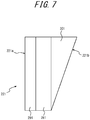
- the liquid crystal panel 22 is configured such that at least a part of the light having passed approximately vertically through the liquid crystal layer 26 is refracted at and exits the second face 22b.
- the second face 22b of the second transmissive member 30 may be inclined relative to the liquid crystal layer 26.
- the second transmissive member 30 may be inclined relative to the boundary with the liquid crystal layer 26.
- the thickness of the second transmissive member 30 may depend on the position. When the thickness of the second transmissive member 30 is different depending on the position, the second face 22b is inclined relative to the face that forms a counterpart to the second face 22b.
- the thickness thereof is adjusted such that the second face 22b is inclined relative to the liquid crystal layer 26.
- the second transmissive member 30 configured in the above described manner may be realized by obliquely polishing the second substrate 27 with respect to the liquid crystal layer 26 after the first substrate 25, the liquid crystal layer 26 and the second substrate 27 are integrally formed. The light having passed through the liquid crystal layer 26 is refracted when passing between the second substrate 27 and the second polarizing plate 28 and when being exits the second face 22b.
- the second transmissive member 30 configured in the above described manner may be realized by attaching the second polarizing plate 28 whose thickness is different depending on the position to the second substrate 27.
- the first transmissive member 29 is configured such that at least a part of the light having entered the first face 22a is refracted at the first face 22a and enters approximately vertically the liquid crystal layer 26.
- the first face 22a of the first transmissive member 29 may be inclined relative to the liquid crystal layer 26.
- the first transmissive member 29 may be inclined relative to the boundary with the liquid crystal layer 26.
- the thickness of the first transmissive member 29 may be different depending on the position. When the thickness of the first transmissive member 29 is different depending on the position, the first face 22a is inclined relative to the face that forms a counterpart to the first face 22a.
- the liquid crystal panel 22 is configured such that the second face 22b that is inclined relative to the liquid crystal layer 26 and the first face 22a are approximately parallel to each other.
- the thickness of the first transmissive member 29 and that of the second transmissive member 30 may be adjusted respectively such that the first face 22a and the second face 22b are approximately parallel to each other.
- both of the first substrate 25 and the second substrate 27 may be obliquely polished simultaneously relative to the liquid crystal layer 26.
- the first polarizing plate 24 whose thickness is different depending on the position may be applied to the first substrate 25.
- the second polarizing plate 28 whose thickness is different depending on the position may be applied to the second substrate 27.
- FIG. 5 illustrates a cross-sectional view of the liquid crystal panel 22 where the second face 22b inclined relative to the liquid crystal layer 26 and the first face 22a are approximately parallel to each other.
- the solid arrow in FIG. 5 indicates a light path along which the light emitted from the light source element 19 and having passed through the third optical member 20 and the fourth optical member 21 passes through the liquid crystal panel 22.
- the liquid crystal panel 22 is fixedly disposed in the liquid crystal display apparatus 16 such that the normal line direction of the second face 22b is inclined relative to the progressive direction of the image projection light emitted from the liquid crystal display apparatus 16. According to such configuration, as described below, the probability is reduced that the external light entering the liquid crystal display apparatus 16 and reflected by the liquid crystal panel 22 travels in the progressive direction of the image projection light emitted from the liquid crystal display apparatus 16.
- the dashed arrow in FIG. 5 illustrates a path along which the external light entering the liquid crystal display apparatus 16 travels. More specifically, as illustrated in FIG. 2 , for example, the external light entering the display apparatus 11 is reflected by or refracted at one or more second optical members 17 and travels opposite to the progressive direction of the image projection light emitted from the liquid crystal display apparatus 16. In FIG. 2 , the external light reflected by two second optical members 17 travels leftward. The external light travelling in the retrograde direction enters the liquid crystal display apparatus 16.
- the second face 22b of the liquid crystal panel 22 reflects at least a part of the external light traveling in the retrograde direction.
- the external light reflected by the second face 22b travels in the direction that is different from the progressive direction of the image projection light emitted from the liquid crystal display apparatus 16. According to such configuration, a decrease in the visibility of the virtual image 13 is reduced. More specifically, if the external light reflected by the liquid crystal panel 22 travels in the progressive direction of the image projection light, the external light arrives at the eye box 15 and may enter the eyes of the user 12. When the external light enters the eyes of the user 12, the visibility of the virtual image 13 may be reduced, for example. According to the liquid crystal panel 22 of an embodiment, the probability is reduced that the external light reflected by the second face 22b of the liquid crystal panel 22 travels in the progressive direction of the image projection light, and thus a decrease in the visibility of the virtual image is reduced.
- the second face 22b may refract a part of the external light traveling in the retrograde direction.
- the external light refracted at the second face 22b travels, in the liquid crystal panel 22, approximately vertically relative to the liquid crystal layer 26.
- the external light traveling in the liquid crystal panel 22 may enter the first face 22a.
- the external light entering the first face 22a may be reflected by the first face 22a.
- the first face 22a is inclined relative to the liquid crystal layer 26. Therefore, the external light reflected by the first face 22a travels, in the liquid crystal panel 22, in the direction different from the direction approximately vertical to the liquid crystal layer 26.
- the external light reflected by the first face 22a and refracted at and exits the second face 22b travels in the direction different from the progressive direction of the image projection light.
- the liquid crystal panel 22 of an embodiment since the probability is reduced that the external light reflected by the first face 22a of the liquid crystal panel 22 travels in the progressive direction of the image projection light, a decrease in the visibility of the virtual image 13 is reduced.
- the liquid crystal panel 22 is fixedly disposed in the liquid crystal display apparatus 16 such that the light emitted from the light source element 19 and traveling approximately parallel to the optical axis of the liquid crystal display apparatus 16 will enter the first face 22a at an incident angle A.
- the incident angle A may be represented by the following formula.
- a rad sin ⁇ 1 n • sinB
- B is an inclination [rad] of the first face 22a relative to the liquid crystal layer 26 and is equal to an angle of refraction
- n is an index of refraction of the first transmissive member 29 with respect to the ambient medium of the liquid crystal panel 22.
- the light entering the first face 22a at an incident angle A and refracted thereby travels in the first transmissive member 29 in the direction approximately vertical to the liquid crystal layer 26.
- the light passes approximately vertically through the liquid crystal layer 26.
- the light having passed through the liquid crystal layer 26 travels in the second transmissive member 30 and enters the second face 22b at an incident angle B.
- the index of refraction of the first transmissive member 29 may be approximately the same as that of the second transmissive member 30. In this case, the light having entered the second face 22b at an incident angle B exits the second face 22b at an emission angle A.
- the controller 23 includes one or more processors.
- the processor may include a general-purpose processor that reads in a specific program to execute a specific function and a processor dedicated to a specific processing.
- the dedicated processor may include Application Specific Integrated Circuit (ASIC).
- the processor may include Programmable Logic Device (PLD).
- the PLD may include Field-Programmable Gate Array (FPGA).
- SoC System-on-a-Chip
- SiP System In a Package
- the controller 23 controls overall operation of the light source apparatus 31. For example, the controller 23 controls the driving power of the light source element 19 to allow the light source element 19 to emit light.
- the driving power control of the light source element 19 may include current control, voltage control and Pulse Width Modulation (PWM) control.
- PWM Pulse Width Modulation
- the controller 23 may adjust the color of the light source element 19.
- Color adjustment of the light source element 19 may include a driving power control performed with respect to each light emitting diode.
- the controller 23 allows the liquid crystal panel 22 to display an image. Images may include characters or graphics.
- the second face 22b of the liquid crystal panel 22 is inclined relative to the liquid crystal layer 26. Therefore, at least a part of the light passing substantially vertically through the liquid crystal layer 26 is refracted at and exits the second face 22b.
- the convenience of the liquid crystal panel 22, the liquid crystal display apparatus 16, the display apparatus 11 and the moving body 10 is improved.
- the external light traveling opposite to the progressive direction of the image projection light may enter the second face 22b of the liquid crystal panel 22 at an incident angle ⁇ 0 [rad], for example.
- the image projection light may be exits the second face 22b of the liquid crystal panel 22 at an emission angle ⁇ 0 [rad].
- the light emitted from the light source element 19 and passing approximately vertically through the liquid crystal layer 26 may be exits the second face 22b.
- the light emitted from the light source element 19 and passing approximately vertically through the liquid crystal layer 26 may be exits the second face 22b at an emission angle ⁇ 0 [rad].
- the second face 22b of the liquid crystal panel 22 is inclined relative to the liquid crystal layer 26.
- at least a part of the light passing approximately vertically through the liquid crystal layer 26 is refracted at and exits the second face 22b at an emission angle ⁇ 0 [rad].
- the first face 22a of the liquid crystal panel 22 may be inclined relative to the liquid crystal layer 26. According to such configuration, out of the external light entering the second face 22b, the external light refracted at the second face 22b, traveling in the liquid crystal panel 22 and reflected by the first face 22a exits the second face 22b in the direction different from the progressive direction of the image illumination light. Therefore, the probability is reduced that the external light traveling opposite to the progressive direction of the image projection light will be reflected by the first face 22a of the liquid crystal panel 22 and travel in the progressive direction of the image projection light. Thus, since a decline in the visibility of the virtual image 13 due to the external light reflected by the first face 22a of the liquid crystal panel 22 is reduced, the convenience of the liquid crystal panel 22, the liquid crystal display apparatus 16, the display apparatus 11 and the moving body 10 is further improved.
- a moving body 100 and a display apparatus 110 according to an embodiment are described with reference to FIG. 9 .
- the moving body 100 is provided with the display apparatus 110.
- the display apparatus 110 may be disposed at any position in the moving body 100.
- the display apparatus 110 may be disposed in a dashboard of the moving body 100, for example.
- the display apparatus 110 serves as a head-up display that allows a user 120 such as a driver of the moving body 100, for example, to visually recognize a virtual image 130 of a desired image. More specifically, in an embodiment, the display apparatus 110 emits image projection light toward a predetermined region of a fifth optical member 140 provided in the moving body 100.
- the fifth optical member 140 may be a windshield.
- the fifth optical member 140 may be a combiner. The details of the image projection light will be described later.
- the image projection light reflected by the predetermined region of the fifth optical member 140 arrives at an eye box 150.
- the eye box 150 is an area in a real space where eyes of the user 120 are assumed to be present in light of a build, a posture, a change in the posture and the like of the user 120, for example.
- the solid arrow in FIG. 9 illustrates a path along which a part of the image projection light emitted from the display apparatus 110 arrives at the eye box 150.
- the user 120 can visually recognize the virtual image 130 of the image by the image projection light arrived at the eye box 150.
- the virtual image 130 may be visually recognized in front of the moving body 100, for example.
- the external light such as sunlight and the like may pass through the fifth optical member 140 and enter the display apparatus 110 along a path opposite to the path along which the image projection light travels.
- the dashed arrow in FIG. 9 illustrates a path along which the external light enters the display apparatus 110. Details of the external light entering the display apparatus 110 will be described later.
- the display apparatus 110 includes a light source apparatus 160 and one or more sixth optical members 170.
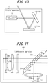
- FIG. 10 illustrates a configuration in which the display apparatus 110 is provided with two sixth optical members 170a and 170b.
- the light source apparatus 160 emits image projection light in the display apparatus 110.
- the detailed configuration of the light source apparatus 160 will be described later.
- the sixth optical members 170a and 170b allow the image projection light emitted from the light source apparatus 160 to reach the outside of the display apparatus 110.
- at least one of the sixth optical members 170a and 170b may be a mirror.
- the solid arrow illustrated in FIG. 10 indicates a path along which a part of the image projection light emitted from the light source apparatus 160 is reflected by the sixth optical members 170a and 170b, passes through a window provided in the housing of the display apparatus 110 and reaches the outside of the display apparatus 110.
- the image projection light reached the outside of the display apparatus 110 reaches a predetermined region of the fifth optical member 140 provided in the moving body 100, as illustrated in FIG. 9 .
- at least one of the sixth optical members 170a and 170b may be a lens.
- one of the sixth optical members 170a and 170b may be a mirror and the other may be a lens.
- the sixth optical members 170a and 170b may serve as an expansion optical system that expands the image projection light.
- at least one of the sixth optical members 170a and 170b may be a mirror having a convex or a concave shape at least a part on the surface where the image projection light arrives at.
- at least one of the sixth optical members 170a and 170b may be a lens having a convex or a concave shape at least a part on the surface where the image projection light enters or exits. At least a part of the convex shape and the concave shape may be sphere or non-sphere.
- the external light entering the display apparatus 110 may enter the light source apparatus in the display apparatus 110 along a path opposite to the path along which the image projection light travels.
- the dashed arrow illustrated in FIG. 10 is a path along which the external light enters the light source apparatus 160. The details of the external light entering the light source apparatus 160 will be described later.
- the light source apparatus 160 includes a substrate 180, a light source element 190, a seventh optical member 200, an eighth optical member 210, a liquid crystal panel 223, a beam splitter 240, a controller 230 and a light guiding member 250.
- the substrate 180, the seventh optical member 200, the eighth optical member 210, the liquid crystal panel 223 and the light guiding member 250 are fixedly disposed in the light source apparatus 160.
- the light source element 190 and the controller 230 are disposed on the substrate 180.
- the light source element 190 includes one or more Light Emitting Diodes (LED) or a laser apparatus and the like, for example.
- the light source element 190 emits light according to the control by the controller 230.
- the light source element 190 may include a plurality of light emitting diodes, the colors of lights emitted from respective light emitting diodes being different from each other.
- the solid arrow extending from the light source element 190 illustrates a path along which a part of the light emitted from the light source element 190 travels.
- the progressive direction of the light emitted from the light source element in the light path is approximately coincident with the first direction.
- the seventh optical member 200 is located in the first direction (the right direction in FIG. 11 ) of the light source element 190.
- the seventh optical member 200 includes a collimator lens, for example.
- the seventh optical member 200 collimates the light having entered from the light source element 190.
- the collimated light is approximately parallel light traveling in the optical axis direction of the seventh optical member 200.
- the eighth optical member 210 is located in the first direction of the seventh optical member 200.
- the eighth optical member 210 includes a lens, for example.
- the eighth optical member 210 may include a Fresnel lens.
- the eighth optical member 210 is fixedly disposed in the light source apparatus 160 such that the optical axis of the eighth optical member 210 is approximately aligned with the optical axis of the seventh optical member 200.
- the optical axis of the seventh optical member 200 (or the eighth optical member 210) is also referred to as an optical axis of the light source apparatus 160.
- the above described first direction and the optical axial direction of the light source apparatus 160 are approximately parallel to each other.
- the eighth optical member 210 refracts the light having passed through and collimated by the seventh optical member 200 in a desired progressive direction.
- the liquid crystal panel 223 includes a transmissive liquid crystal device such as a Liquid Crystal Display (LCD), for example.
- the liquid crystal panel 223 is located in the first direction of the eighth optical member 210. Therefore, as illustrated in FIG. 11 , for example, the light source element 190, the seventh optical member 200, the eighth optical member 210 and the liquid crystal panel 223 are disposed, in this order, along the optical axis of the light source apparatus 160.
- the liquid crystal panel 223 can display a variety of images by a liquid crystal layer driven according to the control by the controller 230.
- the liquid crystal panel 223 transmits or shields the light having passed through the eighth optical member 210 by the liquid crystal layer, and thus emits the image projection light to the outside of the light source apparatus 160.
- the light from the light source element 190 enters the first face 223a of the liquid crystal panel 223 via the seventh optical member 200 and the eighth optical member 210. At least a part of the light having entered the first face 223a of the liquid crystal panel 223 is polarized in a predetermined polarization direction in the liquid crystal layer driven according to the control by the controller 230 and passes through the liquid crystal layer. Linear polarized light having passed through the liquid crystal layer exits a second face 223b of the liquid crystal panel 223.
- the linear polarized light emitted from the second face 223b of the liquid crystal panel 223 is also referred to as image projection light.
- the second face 223b of the liquid crystal panel 223 is inclined relative to a plane vertical to the first direction. In another embodiment, the second face 223b of the liquid crystal panel 223 may be approximately vertical to the first direction.
- the beam splitter 240 is located in the first direction of the liquid crystal panel 223.
- the beam splitter 240 divides the light having obliquely entered relative to the beam splitter 240 into two.
- the beam splitter 240 may be a polarization beam splitter configured to, out of the light having entered, allow a component of the first polarization direction to pass through and reflect a component of the second polarization direction orthogonal to the first polarization direction.
- the beam splitter 240 may be a half mirror, for example.
- the beam splitter 240 is disposed such that it is inclined relative to a plane vertical to the first direction.
- the image projection light emitted from the second face 223b of the liquid crystal panel 223 and traveling in the first direction obliquely enters the beam splitter 240.
- the beam splitter 240 is disposed such that the first polarization direction is approximately coincident with the polarization direction of the entering image projection light. Therefore, the beam splitter 240 allows the image projection light emitted from the liquid crystal panel 223 and traveling in the first direction to pass through.
- the beam splitter 240 and the second face 223b of the liquid crystal panel 223 may be in contact or separate with each other.
- the liquid crystal panel 223 and the beam splitter 240 may be integrally formed such that the beam splitter 240 and the second face 223b of the liquid crystal panel 223 may be in contact with each other.
- the beam splitter 240 may be formed into a sheet and may be attached to the second face 223b of the liquid crystal panel 223.
- the beam splitter 240 reflects at least a part of the external light having entered the light source apparatus 160.
- the dashed arrow in FIG. 11 illustrates a path along which at least a part of the external light entering the light source element 190 travels. More specifically, as illustrated in FIG. 10 , for example, the external light entering the display apparatus 110 is reflected by or refracted at one or more second optical elements and travels in the second direction (to the left in FIG. 10 ) opposite to the first direction. In an embodiment, the retrograde direction opposite to the progressive direction of the light emitted from the light source element in the light path is approximately coincident with the second direction. The external light traveling in the second direction enters the light source apparatus 160.
- the beam splitter 240 allows a component of the first polarization direction to pass through and reflects a component of the second polarization direction.
- the external light having passed through the beam splitter 240 is reflected by the second face 223b of the liquid crystal panel 223 inclined relative to the plane vertical to the first direction and travels in the direction other than the first direction.
- the external light reflected by the beam splitter 240 travels in the direction other than the first direction.
- the progressive direction of the external light reflected by the second face 223b of the liquid crystal panel 223 may be approximately coincident with that of the external light reflected by the beam splitter 240.
- the external light reflected by the second face 223b of the liquid crystal panel 223 and the light reflected by the beam splitter 240 travel respectively in the third direction (downward direction in FIG. 11 ) that is different from the first direction.
- the progressive direction of the external light reflected by the second face 223b of the liquid crystal panel 223 and the progressive direction of the external light reflected by the beam splitter 240 may be different from each other.
- the controller 230 includes one or more processors.
- the processors may include a general-purpose processor that reads in a specific program to execute a specific function and a processor dedicated to a specific processing.
- the dedicated processor may include Application Specific Integrated Circuit (ASIC).
- the processor may include Programmable Logic Device (PLD).
- the PLD may include Field-Programmable Gate Array (FPGA).
- the controller 230 may be either System-on-a-Chip (SoC) in which one or more processors corporate with each other or System In a Package (SiP).
- SoC System-on-a-Chip
- SiP System In a Package
- the controller 230 controls overall operation of the light source apparatus 160. For example, the controller 230 controls the driving power of the light source element 190 to allow the light source element 19 to emit light.
- the driving power control of the light source element 190 may include current control, voltage control and Pulse Width Modulation (PWM) control.
- PWM Pulse Width Modulation
- the controller 230 may adjust the color of the light source element 190.
- Color adjustment of the light source element 190 may include a driving power control performed with respect to each light emitting diode.
- the controller 230 allows the liquid crystal panel 223 to display an image.
- the image may include characters or graphics.
- the light guiding member 250 guides and allows the external light reflected by the beam splitter 240 to enter the first face 223a of the liquid crystal panel 223.
- the light guiding member 250 includes a lens 320 configured to collect external light reflected by the beam splitter 240 and an optical fiber 330 configured to allow the collected external light to enter a first end 330a and to emit the external light from a second end 330b.
- the second end 330b of the optical fiber 330 may be disposed in the vicinity of the light source element 190. In the vicinity of the optical element is a position where the light from the second end 330b of the optical fiber 330 is emitted in the same space where the light from the optical element is emitted, for example.
- the light from the second end 330b of the optical fiber 330 enters the first face 223a of the liquid crystal panel 223 via the seventh optical member 200 and the eighth optical member 210.
- the solid arrow extending from the second end 330b of the optical fiber 330 indicates a path along which a part of the light emitted from the second end 330b travels.
- the light guiding member 250 may further include a diffusion member connected to the second end 330b of the optical fiber 330.
- the diffusion member may include a light diffusion plate or a light diffusion fiber, for example.
- the diffusion member diffuses the external light emitted from the second end 330b of the optical fiber 330.
- the light from the diffusion member enters the first face 223a of the liquid crystal panel 223 via the seventh optical member 200 and the eighth optical member 210.
- the diffusion member includes a light diffusion fiber
- the light diffusion fiber may be bent such that it covers around the light source element 190, for example, and may be disposed on the substrate 180.
- the light source apparatus 160 may further include a diffusion plate between the eighth optical member 210 and the liquid crystal panel 223.
- the beam splitter 240 allows the image projection light emitted from the liquid crystal panel 223 and traveling in the first direction to pass through and reflects the external light traveling in the second direction opposite to the first direction in the direction different from the first direction. According to such configuration, as described below, the light source apparatus 160 with improved convenience is realized.
- the second face 223b of the liquid crystal panel 223 is approximately vertical to the first direction and the beam splitter 240 is not provided.
- the external light entering the light source apparatus is reflected by the second face 223b of the liquid crystal panel 223 and travels in the first direction.
- the external light reflected by the liquid crystal panel 223 and traveling in the first direction is emitted from the light source apparatus along with the image projection light.
- the light source apparatus including no beam splitter 240 since the external light reflected by the liquid crystal panel 223 reaches the eye box 150, the visibility of the virtual image 130 is decreased.
- the light source apparatus 160 of an embodiment since the external light having entered the light source apparatus 160 is reflected in the direction different from the first direction, the possibility that the reflected external light reaches the eye box 150 is decreased. Since the visibility of the virtual image 130 is decreased, the convenience of the light source apparatus 160 and of the display apparatus 110 and the moving body 100 provided with the light source apparatus 160 is improved.
- the light guiding member 250 guides and allows the external light reflected by the beam splitter 240 to enter the first face 223a of the liquid crystal panel 223.
- the external light entering the light source apparatus 160 can be used as what is called back light.
- the brightness of the image projection light is increased and the visibility of the virtual image 130 is improved.
- the light entering the liquid crystal panel 223 from the light guiding member 250 is bright enough, even if the emission intensity of the light source element 190 is weak, the visibility of the virtual image 130 is maintained.
- the amount of power to drive the light source element 190 can be reduced. Therefore, the convenience of the light source apparatus 160 and of the display apparatus 110 and the moving body 100 provided with the light source apparatus 160 is improved.
- the second face 223b of the liquid crystal panel 223 may be inclined relative to a plane vertical to the first direction.
- the first face 22a of the liquid crystal panel 22 and the second face 22b that is inclined relative to the liquid crystal layer 26 are approximately parallel to each other.
- the second face 22b is inclined relative to the liquid crystal layer 26, and it is not essential that the first face 22a and the second face 22b are approximately parallel to each other.
- the absolute value of the angle formed by the liquid crystal layer 260 and the first face 220a is smaller than that formed by the liquid crystal layer 260 and the second face 220b.
- the first face 221a is parallel to the liquid crystal layer 261, and on the other hand the second face 221b is inclined relative to the liquid crystal layer 261.
- the first face 222a and the second face 222b are not approximately parallel to each other. Even if any of the above described liquid crystal panels 220, 221 and 222 is adopted, as with the above described embodiment, a decrease in the visibility of the virtual image 13 can be reduced.
- the first polarizing plate 24, the first substrate 25, the liquid crystal layer 26, the second substrate 27 and the second polarizing plate 28 are integrally formed.
- each component of the liquid crystal panel 22 may be separated.
- at least one of the first polarizing plate 24 and the second polarizing plate 28 may be separated from the liquid crystal panel 22.
- the moving body 100 may further include a polarizing filter on the fourth face of the fifth optical member 140 (for example, the windshield), the fourth face being different from the third face that reflects image projection light.
- the third face is a face of the fifth optical member 140 opposed to the inner space of the moving body 100.
- the fourth face is a face of the fifth optical member 140 opposed to the outer space of the moving body 100.
- the polarizing filter attenuates or shields a component of a predetermined polarization direction.
- the polarizing filter is provided on the fourth face of the fifth optical member 140 such that the predetermined polarization direction is approximately coincident with the polarization direction of the image projection light that reaches the fifth optical member 140.
- the light source apparatus 160 may further include a first sensor configured to detect brightness of an image displayed by the liquid crystal panel 223, that is, brightness of the image projection light.
- the first sensor may include a photodetector such as a photodiode or a photo transistor, for example.
- the first sensor may be disposed in the first direction of the liquid crystal panel 223 or the beam splitter 240, for example, of the light source apparatus 160.
- the controller 230 controls the driving power of the light source element 190 depending on the detection value of the first sensor. More specifically, when the detection value of the first sensor is a threshold or more, the controller 230 decreases the amount of power to drive the light source element 190 to reduce the brightness of the light from the light source element 190.
- the image projection light includes the light from the light source element 190 and the light from the light guiding member 250.
- the first sensor may be provided in the display apparatus 110 or the moving body 100, instead of the light source apparatus 160.
- the light source apparatus 160 may further include a second sensor configured to detect color temperatures of the external light entering the first face 223a of the liquid crystal panel 223 from the light guiding member 250 or of the photosynthesis of the external light and the light from the light source element 190.
- the second sensor may include a color thermometer, for example.
- the second sensor may be disposed in a space between the substrate 180 and the seventh optical member 200, for example.
- the controller 230 adjusts the color of the light source element 190 depending on the detection value of the second sensor.
- the controller 230 controls the driving power of each light emitting diode included in the light source element 190 such that each of R,G, and B will be a desired percent value, for example. According to such configuration, change of the color tone of the image projection light from a desired color tone due to the external light entering the first face 223a of the liquid crystal panel 223 from the light guiding member 250 can be reduced, for example. Thus, the convenience of the light source apparatus 160 and of the display apparatus 110 and the moving body 100 provided with the light source apparatus 160 is further improved.
Landscapes
- Physics & Mathematics (AREA)
- Chemical & Material Sciences (AREA)
- Engineering & Computer Science (AREA)
- Nonlinear Science (AREA)
- Optics & Photonics (AREA)
- General Physics & Mathematics (AREA)
- Transportation (AREA)
- Combustion & Propulsion (AREA)
- Mechanical Engineering (AREA)
- Crystallography & Structural Chemistry (AREA)
- Mathematical Physics (AREA)
- Inorganic Chemistry (AREA)
- Liquid Crystal (AREA)
- Instrument Panels (AREA)
Abstract
Description
- This application claims priority from and the benefit of Japanese Patent Application Nos.
2016-167333 filed on August 29, 2016 2016-192183 filed on September 29, 2016 - This disclosure relates to a liquid crystal panel, a liquid crystal display apparatus, a display apparatus, a moving body and a light source apparatus.
- An apparatus that is mounted on a moving body such as a vehicle and allows a user such as a driver to visually recognize a virtual image is conventionally known. For example, Patent Literature 1 (PTL 1) discloses a technique to control the light intensity of a light source depending on the ambient brightness.
- PTL 1:
JP 2015-168382 A - A liquid crystal panel according to an embodiment of this disclosure includes a first transmissive member, a liquid crystal layer and a second transmissive member. The first transmissive member has a first face. Light enters the first face. The second transmissive member has a second face. At least a part of the light having passed through the first transmissive member and the liquid crystal layer exits the second face. The second face is inclined relative to the liquid crystal layer.
- A liquid crystal panel according to an embodiment of this disclosure includes a first transmissive member, a liquid crystal layer and a second transmissive member. The first transmissive member has a first face. Light enters the first face. The second transmissive member has a second face. At least a part of the light having passed through the first transmissive member and the liquid crystal layer exits the second face. At least a part of the light having passed approximately vertically through the liquid crystal layer is refracted at and exits the second face.
- A liquid crystal display apparatus according to an embodiment of this disclosure includes a light source element and a liquid crystal panel. The light source element emits light. The liquid crystal panel is located in the direction along which the light emitted from the light source element travels. The liquid crystal panel includes a first transmissive member, a liquid crystal layer and a second transmissive member. The first transmissive member has a first face. Light from the light source element enters the first face. The second transmissive member has a second face. At least a part of the light having passed through the first transmissive member and the liquid crystal layer exits the second face. The second face is inclined relative to the liquid crystal layer.
- A liquid crystal display apparatus according to an embodiment of this disclosure includes a light source element and a liquid crystal panel. The light source element emits light. The liquid crystal panel is located in the direction along which the light emitted from the light source element travels. The liquid crystal panel includes a first transmissive member, a liquid crystal layer and a second transmissive member. The first transmissive member has a first face. Light from the light source element enters the first face. The second transmissive member has a second face. At least a part of the light having passed through the first transmissive member and the liquid crystal layer exits the second face. At least a part of the light having passed approximately vertically through the liquid crystal layer is refracted at and exits the second face.
- A display apparatus according to an embodiment of this disclosure includes a light source element, a liquid crystal panel and one or more optical members. The light source element emits light. The liquid crystal panel is located in the direction along which the light emitted from the light source element travels. The liquid crystal panel has a first transmissive member, a liquid crystal layer and a second transmissive member. The first transmissive member has a first face. Light from the light source element enters the first face. The second transmissive member has a second face. At least a part of the light having passed through the first transmissive member and the liquid crystal layer exits the second face. The one or more optical members allow the light having exited the second face to reach a predetermined region in a real space. The second face is inclined relative to the liquid crystal layer.
- A display apparatus according to an embodiment of this disclosure includes a light source element, a liquid crystal panel and one or more optical members. The light source element emits light. The liquid crystal panel is located in the direction along which the light emitted from the light source element travels. The liquid crystal panel includes a first transmissive member, a liquid crystal layer and a second transmissive member. The first transmissive member has a first face. Light from the light source element enters the first face. The second transmissive member has a second face. At least a part of the light having passed through the first transmissive member and the liquid crystal layer exits the second face. The one or more optical members allow the light having exited the second face to reach a predetermined region in a real space. At least a part of the light having passed approximately vertically through the liquid crystal layer is refracted at and exits the second face.
- A moving body according to an embodiment of this disclosure includes a light source element, a liquid crystal panel and one or more optical members. The light source element emits light. The liquid crystal panel is located in the direction along which the light emitted from the light source element travels. The liquid crystal panel includes a first transmissive member, a liquid crystal layer and a second transmissive member. The first transmissive member has a first face. Light from the light source element enters the first face. The second transmissive member has a second face. At least a part of the light having passed through the first transmissive member and the liquid crystal layer exits the second face. The one or more optical members allow the light having exited the second face to reach a predetermined region in a real space. The second face is inclined relative to the liquid crystal layer.
- A moving body according to an embodiment of this disclosure includes a light source element, a liquid crystal panel and one or more optical members. The light source element emits light. The liquid crystal panel is located in the direction along which the light emitted from the light source element travels. The liquid crystal panel includes a first transmissive member, a liquid crystal layer and a second transmissive member. The first transmissive member has a first face. Light from the light source element enters the first face. The second transmissive member has a second face. At least a part of the light having passed through the first transmissive member and the liquid crystal layer exits the second face. The one or more optical members allow the light having exited the second face to reach a predetermined region in a real space. At least a part of the light having passed approximately vertically through the liquid crystal layer is refracted at and exits the second face.
- A light source apparatus according to an embodiment of this disclosure includes a light source element, a liquid crystal panel, a beam splitter and a light guiding member. The light source element emits light. The liquid crystal panel is located in the progressive direction in a light path of the light emitted from the light source element. The beam splitter is located in the progressive direction of the liquid crystal panel. The beam splitter is inclined relative to a plane vertical to the progressive direction. The liquid crystal panel has a first face and a second face. Light from the light source element enters the first face. Image projection light resulting from polarization of the light having entered the first face in a predetermined polarization direction exits the second face. The beam splitter allows the image projection light having exited the second face of the liquid crystal panel and traveling in the progressive direction to pass through and also reflects external light traveling in the retrograde direction opposite to the progressive direction in the direction different from the progressive direction. The light guiding member guides and allows the external light reflected by the beam splitter to enter the first face of the liquid crystal panel.
- A display apparatus according to an embodiment of this disclosure allows a user to visually recognize a virtual image of an image. The display apparatus includes a light source element, a liquid crystal panel, a beam splitter, one or more optical members and a light guiding member. The light source element emits light. The liquid crystal panel is located in the progressive direction in a light path of the light emitted from the light source element. The beam splitter is located in the progressive direction of the liquid crystal panel. The beam splitter is inclined relative to a plane vertical to the progressive direction. The liquid crystal panel has a first face and a second face. Light from the light source element enters the first face. Image projection light resulting from polarization of the light having entered the first face in a predetermined polarization direction exits the second face. The beam splitter allows the image projection light having exited the second face of the liquid crystal panel and traveling in the progressive direction to pass through and reflects external light traveling in the retrograde direction opposite to the progressive direction in the direction different from the progressive direction. The one or more optical members allow the image projection light having passed through the beam splitter to reach a predetermined region in a real space. The light guiding member guides and allows the external light reflected by the beam splitter to enter the first face of the liquid crystal panel.
- A moving body according to an embodiment of this disclosure allows a user to visually recognize a virtual image of an image. The moving body includes a light source element, a liquid crystal panel, a beam splitter, one or more optical members and a light guiding member. The light source element emits light. The liquid crystal panel is located in the progressive direction in a light path of the light emitted from the light source element. The beam splitter is located in the progressive direction of the liquid crystal panel. The beam splitter is inclined relative to a plane vertical to the progressive direction. The liquid crystal panel has a first face and a second face. Light from the light source element enters the first face. Image projection light resulting from polarization of the light having entered the first face in a predetermined polarization direction exits the second face. The beam splitter allows the image projection light having exited the second face of the liquid crystal panel and traveling in the progressive direction to pass through and reflects external light traveling in the retrograde direction opposite to the progressive direction in the direction different from the progressive direction. The one or more optical members allow the image projection light having passed through the beam splitter to reach a predetermined region in a real space. The light guiding member guides and allows the external light reflected by the beam splitter to enter the first face of the liquid crystal panel.
- In the accompanying drawings:
-
FIG. 1 is a diagram illustrating a moving body and a display apparatus according to Embodiment 1 of this disclosure; -
FIG. 2 is a diagram illustrating a schematic configuration of the display apparatus inFIG. 1 ; -
FIG. 3 is a cross-sectional view along an optical axis of a liquid crystal display apparatus inFIG. 2 ; -
FIG. 4 is a diagram illustrating a schematic configuration of a liquid crystal panel inFIG. 3 ; -
FIG. 5 is a cross sectional view of the liquid crystal panel inFIG. 3 ; -
FIG. 6 is a cross-sectional view of a liquid crystal panel according to Variation 1 of Embodiment 1 of this disclosure; -
FIG. 7 is a cross-sectional view of a liquid crystal panel according to Variation 2 of Embodiment 1 of this disclosure; -
FIG. 8 is a cross-sectional view of a liquid crystal panel according to Variation 3 of Embodiment 1 of this disclosure; -
FIG. 9 is a diagram illustrating a moving body and a display apparatus according to Embodiment 2 of this disclosure; -
FIG. 10 is a diagram illustrating a schematic configuration of the display apparatus inFIG. 9 ; and -
FIG. 11 is a cross-sectional view along an optical axis of a light source apparatus inFIG. 10 . - Improvement of convenience is conventionally desired for an apparatus configured to allow a user to visually recognize a virtual image. According to a liquid crystal panel, a liquid crystal display apparatus, a display apparatus, a moving body and a light source apparatus of an embodiment of this disclosure, convenience is improved. Embodiments of this disclosure will be described below with reference to drawings.
- A moving
body 10 and adisplay apparatus 11 according to Embodiment 1 will be described with reference toFIG. 1 . The movingbody 10 is provided with adisplay apparatus 11. - The moving
body 10 may include, for example, vehicles, ships, aircrafts and the like. Vehicles may include, for example, automobiles, industrial vehicles, rail vehicles, campers, fixed-wing airplanes running on runway, and the like. Automobiles may include, for example, passenger cars, trucks, buses, two-wheel vehicles, trolleybuses and the like. Industrial vehicles may include, for example, agricultural and construction industrial vehicles and the like. Industrial vehicles may include, for example, forklifts, golf carts and the like. Agricultural industrial vehicles may include, for example, tractors, tillers, transplanters, binders, combines, lawn mowers and the like. Construction industrial vehicles may include, for example, bulldozers, scrapers, loading shovels, crane vehicles, dump trucks, road rollers and the like. Vehicles may include human-powered vehicles. Vehicle classification is not limited to the above described examples. For example, automobiles may include industrial vehicles that can travel on the road. Same vehicle may be included in some categories. Ships may include, for example, jet ski bikes, boats, tankers and the like. Aircrafts may include, for example, fixed-wing airplanes, rotor-wing airplanes and the like. - The
display apparatus 11 may be disposed at any positions in the movingbody 10. Thedisplay apparatus 11 may be disposed in a dashboard of the movingbody 10, for example. Thedisplay apparatus 11 serves as a part of a head-up display that allows auser 12 such as a driver of the movingbody 10, for example, to visually recognize avirtual image 13 of a desired image. More specifically, in an embodiment, thedisplay apparatus 11 emits image projection light toward a predetermined region of a firstoptical member 14 provided in the movingbody 10. In an embodiment, the firstoptical member 14 may be a windshield. In another embodiment, the firstoptical member 14 may be a combiner. When thedisplay apparatus 11 has the firstoptical member 14, thedisplay apparatus 11 serves as a head-up display. Details of the image projection light will be described later. The image projection light reflected by a predetermined region of the firstoptical member 14 arrives at aneye box 15. Theeye box 15 is a region in a real space where eyes of theuser 12 are supposed to be present in light of a build, a posture, a change in the posture and the like of theuser 12, for example. The solid arrow inFIG. 1 illustrates a path along which a part of the image projection light emitted from thedisplay apparatus 11 arrives at theeye box 15. Hereinafter a path along which the light travels is also referred to as a light path. When eyes are present in theeye box 15, theuser 12 can visually recognize avirtual image 13 of an image by the image projection light arrived at theeye box 15. Thevirtual image 13 can be visually recognized in front of the movingbody 10, for example. Thedisplay apparatus 11, in cooperation with the firstoptical member 14, allows theuser 12 such as a driver of the movingbody 10 to visually recognize thevirtual image 13 of the desired image. - For example, external light such as sunlight and the like may pass through the first
optical member 14 and enter thedisplay apparatus 11 along a path in the direction opposite to the path along which the image projection light travels. The dashed arrow inFIG. 1 illustrates a path of the external light entering thedisplay apparatus 11. Details of the external light entering thedisplay apparatus 11 will be described later. - The
display apparatus 11 according to an embodiment will be described in detail with reference toFIG. 2 . Thedisplay apparatus 11 includes a liquidcrystal display apparatus 16 and one or more secondoptical members 17.FIG. 2 illustrates a configuration in which thedisplay apparatus 11 includes two secondoptical members FIG. 2 schematically illustrates an example of configuration of thedisplay apparatus 11. For example, the size, the shape and the arrangement and the like of thedisplay apparatus 11 and each component of thedisplay apparatus 11 are not limited to the example illustrated inFIG. 2 . - The liquid
crystal display apparatus 16 emits image projection light in thedisplay apparatus 11. The detailed configuration of the liquidcrystal display apparatus 16 will be described later. - The second
optical member 17 allows the image projection light emitted from the liquidcrystal display apparatus 16 to arrive at the outside of thedisplay apparatus 11. In the example illustrated inFIG. 2 , the secondoptical members crystal display apparatus 16 to arrive at the outside of thedisplay apparatus 11. In an embodiment, at least one of the secondoptical members FIG. 2 illustrates a path indicating that a part of the image projection light emitted from the liquidcrystal display apparatus 16 is reflected by the secondoptical members display apparatus 11 and arrives at the outside of thedisplay apparatus 11. The image projection light arrived at the outside of thedisplay apparatus 11 arrives at a predetermined region of the firstoptical member 14 provided in the movingbody 10, as illustrated inFIG. 1 . In another embodiment, at least one of the secondoptical members optical members - Furthermore, the second
optical members optical members optical members - As described above, the external light having entered the
display apparatus 11 may, in thedisplay apparatus 11, enter the liquidcrystal display apparatus 16 by a path opposite to the path along which the image projection light travels. The dashed arrow inFIG. 2 illustrates a path of the external light that enters the liquidcrystal display apparatus 16. The external light entering the liquidcrystal display apparatus 16 will be described in detail later. - Details of the liquid
crystal display apparatus 16 according to an embodiment will be described with reference toFIG. 3 . The liquidcrystal display apparatus 16 includes asubstrate 18, alight source element 19, a thirdoptical member 20, a fourthoptical member 21, aliquid crystal panel 22 and acontroller 23. Thesubstrate 18, thelight source element 19, the thirdoptical member 20 and the fourthoptical member 21 may be configured as onelight source apparatus 31. In this case, the liquidcrystal display apparatus 16 may include theliquid crystal panel 22 and thecontroller 23. Thesubstrate 18, the thirdoptical member 20, the fourthoptical member 21 and theliquid crystal panel 22 may be fixedly disposed in the liquidcrystal display apparatus 16. Thelight source element 19 may be disposed on thesubstrate 18.FIG. 3 schematically illustrates an example of a configuration of the liquidcrystal display apparatus 16. For example, the size, the shape and the arrangement and the like of the liquidcrystal display apparatus 16 and each component of the liquidcrystal display apparatus 16 are not limited to the example illustrated inFIG. 3 . - The
light source element 19 includes one or more Light Emitting Diodes (LED) or a laser apparatus and the like. Thelight source element 19 may emit light according to the control of thecontroller 23. Thelight source element 19 may include a plurality of light emitting diodes, the colors of lights emitted from respective diodes being different from each other. InFIG. 3 , the solid arrow extending from thelight source element 19 schematically illustrates a path along which a part of the light emitted from thelight source element 19 travels. Hereinafter at least a part of the light emitted from thelight source element 19 is also referred to merely as the light from thelight source element 19. InFIG. 3 , the light path of the light passing through theliquid crystal panel 22 is schematically illustrated. The details of the light path of the light passing through theliquid crystal panel 22 will be described later. - The third
optical member 20 is located, with respect to the position of thelight source element 19, in the direction along which the light from thelight source element 19 travels. For example, inFIG. 3 , the thirdoptical member 20 is located to the right of thelight source element 19. The thirdoptical member 20 includes a collimator lens, for example. The thirdoptical member 20 collimates light entering from thelight source element 19. The collimated light may be the light traveling in approximately parallel to the optical axial direction of the thirdoptical member 20. - The fourth
optical member 21 is located, with respect to the position of the thirdoptical member 20, in the direction along which the light from thelight source element 19 travels. For example, inFIG. 3 , the fourthoptical member 21 is located to the right of the thirdoptical member 20. The fourthoptical member 21 includes a lens, for example. In an embodiment, the fourthoptical member 21 may include a Fresnel lens. The fourthoptical member 21 is fixedly disposed in the liquidcrystal display apparatus 16 such that the optical axis of the fourthoptical member 21 is approximately aligned with the optical axis of the thirdoptical member 20. Hereinafter the optical axis of the thirdoptical member 20 or the optical axis of the fourthoptical member 21 is also referred to as the optical axis of the liquidcrystal display apparatus 16 or the optical axis of thelight source apparatus 31. In an embodiment, the progressive direction of the image projection light emitted from the liquidcrystal display apparatus 16 and the optical axis direction of the liquidcrystal display apparatus 16 may be approximately parallel to each other. The fourthoptical member 21 may refract at least a part of the light having passed through and collimated by the thirdoptical member 20 in a desired progressive direction. - The
liquid crystal panel 22 includes a transmissive liquid crystal device such as a Liquid Crystal Display (LCD), for example. Theliquid crystal panel 22 is located in the direction along which the light from thelight source element 19 travels with respect to the position of the fourthoptical member 21. For example, inFIG. 3 , theliquid crystal panel 22 is located to the right of the fourthoptical member 21. In an embodiment, as illustrated inFIG. 3 , for example, thelight source element 19, the thirdoptical member 20, the fourthoptical member 21 and theliquid crystal panel 22 may be disposed, in this order, along the optical axis of the liquidcrystal display apparatus 16. The light emitted from thelight source element 19 and having passed through the fourthoptical member 21 enters thefirst face 22a of theliquid crystal panel 22. The light emitted from thelight source apparatus 31 enters theliquid crystal panel 22 from thefirst face 22. With respect to theliquid crystal panel 22, thefirst face 22a may be a face where the light from thelight source apparatus 31 enters. Thefirst face 22a may be a face where the light from thelight source apparatus 31 is received. Thefirst face 22a may be a face located on the light source side in a light path extending from thelight source element 19 to theuser 12. At least a part of the light having passed through theliquid crystal panel 22 exits thesecond face 22b of theliquid crystal panel 22. Thesecond face 22b is a face that emits light that is emitted from thelight source apparatus 31 and passed through theliquid crystal layer 26. Thesecond face 22b may be a face located on theuser 12 side in the light path extending from thelight source element 19 to theuser 12. In an embodiment, thefirst face 22a may face the inside of the liquidcrystal display apparatus 16. Thesecond face 22b may face the outside of the liquidcrystal display apparatus 16. Hereinafter the light exiting thesecond face 22b of theliquid crystal panel 22 is referred to also as the image projection light. - Configuration of the
liquid crystal panel 22 according to an embodiment will be described in detail. As illustrated inFIG. 4 , for example, theliquid crystal panel 22 includes a firstpolarizing plate 24, afirst substrate 25, aliquid crystal layer 26, asecond substrate 27 and a secondpolarizing plate 28. Thefirst substrate 25 may include a transparent electrode and an oriented film. Thesecond substrate 27 may include a transparent electrode and an oriented film. In an embodiment, the firstpolarizing plate 24 may have thefirst face 22a. The secondpolarizing plate 28 may have thesecond face 22b. Hereinafter the firstpolarizing plate 24 and thefirst substrate 25 are collectively also referred to as afirst transmissive member 29. Thesecond substrate 27 and the secondpolarizing plate 28 are collectively also referred to as asecond transmissive member 30. Theliquid crystal panel 22 may include a light diffusion plate, a reflective plate and a color filter. The light diffusion plate, the reflective plate and the color filter may be located on inside or outside of the firstpolarizing plate 24, thefirst substrate 25, thesecond substrate 27 and the secondpolarizing plate 28. For example, in the liquid crystal panel where the diffusion plate is located on thelight source element 19 side of the firstpolarizing plate 24, the face on thelight source element 19 side of the diffusion plate may be defined as the first face. For example, in the liquid crystal panel where the reflective plate is located on theuser 12 side of the secondpolarizing plate 28, for example, the face on theuser 12 side of the reflective plate may be defined as the second face. -
FIG. 4 schematically illustrates an example of a configuration of theliquid crystal panel 22. For example, inFIG. 4 , each of components integrally provided in practice is illustrated separately. Additional members may be present between two components. The size, the shape, the thickness and the like of eachliquid crystal panel 22 and each component of theliquid crystal panel 22 are not limited to those of the example illustrated inFIG. 4 . Theliquid crystal panel 22 can display a variety of images when a voltage is applied to theliquid crystal layer 26. Actuation of theliquid crystal layer 26 may be controlled by thecontroller 23, for example. - In an embodiment, the
liquid crystal panel 22 is configured such that at least a part of the light having passed approximately vertically through theliquid crystal layer 26 is refracted at and exits thesecond face 22b. For example, as illustrated inFIG. 5 , thesecond face 22b of thesecond transmissive member 30 may be inclined relative to theliquid crystal layer 26. Thesecond transmissive member 30 may be inclined relative to the boundary with theliquid crystal layer 26. The thickness of thesecond transmissive member 30 may depend on the position. When the thickness of thesecond transmissive member 30 is different depending on the position, thesecond face 22b is inclined relative to the face that forms a counterpart to thesecond face 22b. For example, with respect to thesecond transmissive member 30, the thickness thereof is adjusted such that thesecond face 22b is inclined relative to theliquid crystal layer 26. Thesecond transmissive member 30 configured in the above described manner may be realized by obliquely polishing thesecond substrate 27 with respect to theliquid crystal layer 26 after thefirst substrate 25, theliquid crystal layer 26 and thesecond substrate 27 are integrally formed. The light having passed through theliquid crystal layer 26 is refracted when passing between thesecond substrate 27 and the secondpolarizing plate 28 and when being exits thesecond face 22b. Thesecond transmissive member 30 configured in the above described manner may be realized by attaching the secondpolarizing plate 28 whose thickness is different depending on the position to thesecond substrate 27. - In an embodiment, the
first transmissive member 29 is configured such that at least a part of the light having entered thefirst face 22a is refracted at thefirst face 22a and enters approximately vertically theliquid crystal layer 26. For example, thefirst face 22a of thefirst transmissive member 29 may be inclined relative to theliquid crystal layer 26. Thefirst transmissive member 29 may be inclined relative to the boundary with theliquid crystal layer 26. The thickness of thefirst transmissive member 29 may be different depending on the position. When the thickness of thefirst transmissive member 29 is different depending on the position, thefirst face 22a is inclined relative to the face that forms a counterpart to thefirst face 22a. - In an embodiment, as described above, the
liquid crystal panel 22 is configured such that thesecond face 22b that is inclined relative to theliquid crystal layer 26 and thefirst face 22a are approximately parallel to each other. For example, the thickness of thefirst transmissive member 29 and that of thesecond transmissive member 30 may be adjusted respectively such that thefirst face 22a and thesecond face 22b are approximately parallel to each other. For example, after thefirst substrate 25, theliquid crystal layer 26 and thesecond substrate 27 are integrally formed, both of thefirst substrate 25 and thesecond substrate 27 may be obliquely polished simultaneously relative to theliquid crystal layer 26. For example, the firstpolarizing plate 24 whose thickness is different depending on the position may be applied to thefirst substrate 25. The secondpolarizing plate 28 whose thickness is different depending on the position may be applied to thesecond substrate 27. - Arrangement of the
liquid crystal panel 22 in the liquidcrystal display apparatus 16 will be described in detail.FIG. 5 illustrates a cross-sectional view of theliquid crystal panel 22 where thesecond face 22b inclined relative to theliquid crystal layer 26 and thefirst face 22a are approximately parallel to each other. The solid arrow inFIG. 5 indicates a light path along which the light emitted from thelight source element 19 and having passed through the thirdoptical member 20 and the fourthoptical member 21 passes through theliquid crystal panel 22. - In an embodiment, the
liquid crystal panel 22 is fixedly disposed in the liquidcrystal display apparatus 16 such that the normal line direction of thesecond face 22b is inclined relative to the progressive direction of the image projection light emitted from the liquidcrystal display apparatus 16. According to such configuration, as described below, the probability is reduced that the external light entering the liquidcrystal display apparatus 16 and reflected by theliquid crystal panel 22 travels in the progressive direction of the image projection light emitted from the liquidcrystal display apparatus 16. - The dashed arrow in
FIG. 5 illustrates a path along which the external light entering the liquidcrystal display apparatus 16 travels. More specifically, as illustrated inFIG. 2 , for example, the external light entering thedisplay apparatus 11 is reflected by or refracted at one or more secondoptical members 17 and travels opposite to the progressive direction of the image projection light emitted from the liquidcrystal display apparatus 16. InFIG. 2 , the external light reflected by two secondoptical members 17 travels leftward. The external light travelling in the retrograde direction enters the liquidcrystal display apparatus 16. - The
second face 22b of theliquid crystal panel 22 reflects at least a part of the external light traveling in the retrograde direction. The external light reflected by thesecond face 22b travels in the direction that is different from the progressive direction of the image projection light emitted from the liquidcrystal display apparatus 16. According to such configuration, a decrease in the visibility of thevirtual image 13 is reduced. More specifically, if the external light reflected by theliquid crystal panel 22 travels in the progressive direction of the image projection light, the external light arrives at theeye box 15 and may enter the eyes of theuser 12. When the external light enters the eyes of theuser 12, the visibility of thevirtual image 13 may be reduced, for example. According to theliquid crystal panel 22 of an embodiment, the probability is reduced that the external light reflected by thesecond face 22b of theliquid crystal panel 22 travels in the progressive direction of the image projection light, and thus a decrease in the visibility of the virtual image is reduced. - The
second face 22b may refract a part of the external light traveling in the retrograde direction. The external light refracted at thesecond face 22b travels, in theliquid crystal panel 22, approximately vertically relative to theliquid crystal layer 26. The external light traveling in theliquid crystal panel 22 may enter thefirst face 22a. The external light entering thefirst face 22a may be reflected by thefirst face 22a. As described above, thefirst face 22a is inclined relative to theliquid crystal layer 26. Therefore, the external light reflected by thefirst face 22a travels, in theliquid crystal panel 22, in the direction different from the direction approximately vertical to theliquid crystal layer 26. Thus, the external light reflected by thefirst face 22a and refracted at and exits thesecond face 22b travels in the direction different from the progressive direction of the image projection light. According to theliquid crystal panel 22 of an embodiment, since the probability is reduced that the external light reflected by thefirst face 22a of theliquid crystal panel 22 travels in the progressive direction of the image projection light, a decrease in the visibility of thevirtual image 13 is reduced. - In an embodiment, the
liquid crystal panel 22 is fixedly disposed in the liquidcrystal display apparatus 16 such that the light emitted from thelight source element 19 and traveling approximately parallel to the optical axis of the liquidcrystal display apparatus 16 will enter thefirst face 22a at an incident angle A. For example, the incident angle A may be represented by the following formula.
- Here, B is an inclination [rad] of the
first face 22a relative to theliquid crystal layer 26 and is equal to an angle of refraction, and n is an index of refraction of thefirst transmissive member 29 with respect to the ambient medium of theliquid crystal panel 22. - The light entering the
first face 22a at an incident angle A and refracted thereby travels in thefirst transmissive member 29 in the direction approximately vertical to theliquid crystal layer 26. The light passes approximately vertically through theliquid crystal layer 26. The light having passed through theliquid crystal layer 26 travels in thesecond transmissive member 30 and enters thesecond face 22b at an incident angle B. In an embodiment, the index of refraction of thefirst transmissive member 29 may be approximately the same as that of thesecond transmissive member 30. In this case, the light having entered thesecond face 22b at an incident angle B exits thesecond face 22b at an emission angle A. - The
controller 23 includes one or more processors. The processor may include a general-purpose processor that reads in a specific program to execute a specific function and a processor dedicated to a specific processing. The dedicated processor may include Application Specific Integrated Circuit (ASIC). The processor may include Programmable Logic Device (PLD). The PLD may include Field-Programmable Gate Array (FPGA). Thecontroller 23 may be either System-on-a-Chip (SoC) in which one or more processors corporate with each other or System In a Package (SiP). Thecontroller 23 controls overall operation of thelight source apparatus 31. For example, thecontroller 23 controls the driving power of thelight source element 19 to allow thelight source element 19 to emit light. The driving power control of thelight source element 19 may include current control, voltage control and Pulse Width Modulation (PWM) control. When thelight source element 19 includes a plurality of light emitting diodes, the colors of lights emitted from respective diodes being different from each other, thecontroller 23 may adjust the color of thelight source element 19. Color adjustment of thelight source element 19 may include a driving power control performed with respect to each light emitting diode. Thecontroller 23 allows theliquid crystal panel 22 to display an image. Images may include characters or graphics. - As described above, in the liquid
crystal display apparatus 16 according to an embodiment, thesecond face 22b of theliquid crystal panel 22 is inclined relative to theliquid crystal layer 26. Therefore, at least a part of the light passing substantially vertically through theliquid crystal layer 26 is refracted at and exits thesecond face 22b. Thus, as described below, since a decrease in the visibility of thevirtual image 13 is reduced, the convenience of theliquid crystal panel 22, the liquidcrystal display apparatus 16, thedisplay apparatus 11 and the movingbody 10 is improved. - Two factors for causing decrease in visibility of the
virtual image 13 will be described. First, when the external light traveling in the retrograde direction opposite to the progressive direction of the image projection light is reflected by thesecond face 22b of theliquid crystal panel 22 and travels in the progressive direction of the image projection light, it can reach theeye box 15. Thus, as described above, the visibility of thevirtual image 13 may decline. Secondly, when the light emitted from thelight source element 19 and traveling in theliquid crystal panel 22 passes through theliquid crystal layer 26, as an inclination of the progressive direction of the light from the direction vertical to theliquid crystal layer 26 increases, the brightness of the image projection light emitted from thesecond face 22b decreases. When the brightness of the image projection light decreases, thevirtual image 13 is dimmed, and the visibility of thevirtual image 13 may decline. - In order to decrease a decline in the visibility of the
virtual image 13 caused by the first factor, the external light traveling opposite to the progressive direction of the image projection light may enter thesecond face 22b of theliquid crystal panel 22 at an incident angle ≠ 0 [rad], for example. In other words, the image projection light may be exits thesecond face 22b of theliquid crystal panel 22 at an emission angle ≠ 0 [rad]. On the other hand, in order to decrease a decline in the visibility of thevirtual image 13 caused by the second factor, the light emitted from thelight source element 19 and passing approximately vertically through theliquid crystal layer 26 may be exits thesecond face 22b. Therefore, in order to decrease the decline in the visibility caused by the first factor and the decline in the visibility caused by the second factor at the same time, the light emitted from thelight source element 19 and passing approximately vertically through theliquid crystal layer 26 may be exits thesecond face 22b at an emission angle ≠ 0 [rad]. - In the liquid
crystal display apparatus 16 according to an embodiment, thesecond face 22b of theliquid crystal panel 22 is inclined relative to theliquid crystal layer 26. Thus, at least a part of the light passing approximately vertically through theliquid crystal layer 26 is refracted at and exits thesecond face 22b at an emission angle ≠ 0 [rad]. According to such configuration, since the decline in the visibility caused by the first factor and that caused by the second factor are decreased at the same time, the convenience of theliquid crystal panel 22, the liquidcrystal display apparatus 16, thedisplay apparatus 11 and the movingbody 10 is improved. - In the liquid
crystal display apparatus 16 according to an embodiment, thefirst face 22a of theliquid crystal panel 22 may be inclined relative to theliquid crystal layer 26. According to such configuration, out of the external light entering thesecond face 22b, the external light refracted at thesecond face 22b, traveling in theliquid crystal panel 22 and reflected by thefirst face 22a exits thesecond face 22b in the direction different from the progressive direction of the image illumination light. Therefore, the probability is reduced that the external light traveling opposite to the progressive direction of the image projection light will be reflected by thefirst face 22a of theliquid crystal panel 22 and travel in the progressive direction of the image projection light. Thus, since a decline in the visibility of thevirtual image 13 due to the external light reflected by thefirst face 22a of theliquid crystal panel 22 is reduced, the convenience of theliquid crystal panel 22, the liquidcrystal display apparatus 16, thedisplay apparatus 11 and the movingbody 10 is further improved. - A moving
body 100 and adisplay apparatus 110 according to an embodiment are described with reference toFIG. 9 . The movingbody 100 is provided with thedisplay apparatus 110. - The
display apparatus 110 may be disposed at any position in the movingbody 100. Thedisplay apparatus 110 may be disposed in a dashboard of the movingbody 100, for example. Thedisplay apparatus 110 serves as a head-up display that allows auser 120 such as a driver of the movingbody 100, for example, to visually recognize avirtual image 130 of a desired image. More specifically, in an embodiment, thedisplay apparatus 110 emits image projection light toward a predetermined region of a fifthoptical member 140 provided in the movingbody 100. In an embodiment, the fifthoptical member 140 may be a windshield. In another embodiment, the fifthoptical member 140 may be a combiner. The details of the image projection light will be described later. The image projection light reflected by the predetermined region of the fifthoptical member 140 arrives at aneye box 150. Theeye box 150 is an area in a real space where eyes of theuser 120 are assumed to be present in light of a build, a posture, a change in the posture and the like of theuser 120, for example. The solid arrow inFIG. 9 illustrates a path along which a part of the image projection light emitted from thedisplay apparatus 110 arrives at theeye box 150. When eyes are present in theeye box 150, theuser 120 can visually recognize thevirtual image 130 of the image by the image projection light arrived at theeye box 150. Thevirtual image 130 may be visually recognized in front of the movingbody 100, for example. - Here, for example, the external light such as sunlight and the like may pass through the fifth
optical member 140 and enter thedisplay apparatus 110 along a path opposite to the path along which the image projection light travels. The dashed arrow inFIG. 9 illustrates a path along which the external light enters thedisplay apparatus 110. Details of the external light entering thedisplay apparatus 110 will be described later. - The
display apparatus 110 according to an embodiment will be described in detail with reference toFIG. 10 . Thedisplay apparatus 110 includes alight source apparatus 160 and one or more sixthoptical members 170.FIG. 10 illustrates a configuration in which thedisplay apparatus 110 is provided with two sixthoptical members - The
light source apparatus 160 emits image projection light in thedisplay apparatus 110. The detailed configuration of thelight source apparatus 160 will be described later. - The sixth
optical members light source apparatus 160 to reach the outside of thedisplay apparatus 110. In an embodiment, at least one of the sixthoptical members FIG. 10 indicates a path along which a part of the image projection light emitted from thelight source apparatus 160 is reflected by the sixthoptical members display apparatus 110 and reaches the outside of thedisplay apparatus 110. The image projection light reached the outside of thedisplay apparatus 110 reaches a predetermined region of the fifthoptical member 140 provided in the movingbody 100, as illustrated inFIG. 9 . In another embodiment, at least one of the sixthoptical members optical members - Furthermore, the sixth
optical members optical members optical members - Here, as described above, the external light entering the
display apparatus 110 may enter the light source apparatus in thedisplay apparatus 110 along a path opposite to the path along which the image projection light travels. The dashed arrow illustrated inFIG. 10 is a path along which the external light enters thelight source apparatus 160. The details of the external light entering thelight source apparatus 160 will be described later. - The
light source apparatus 160 according to an embodiment will be described in detail with reference toFIG. 11 . Thelight source apparatus 160 includes asubstrate 180, alight source element 190, a seventhoptical member 200, an eighthoptical member 210, aliquid crystal panel 223, abeam splitter 240, acontroller 230 and alight guiding member 250. Thesubstrate 180, the seventhoptical member 200, the eighthoptical member 210, theliquid crystal panel 223 and thelight guiding member 250 are fixedly disposed in thelight source apparatus 160. Thelight source element 190 and thecontroller 230 are disposed on thesubstrate 180. - The
light source element 190 includes one or more Light Emitting Diodes (LED) or a laser apparatus and the like, for example. Thelight source element 190 emits light according to the control by thecontroller 230. Thelight source element 190 may include a plurality of light emitting diodes, the colors of lights emitted from respective light emitting diodes being different from each other. InFIG. 11 , the solid arrow extending from thelight source element 190 illustrates a path along which a part of the light emitted from thelight source element 190 travels. In an embodiment, the progressive direction of the light emitted from the light source element in the light path is approximately coincident with the first direction. - The seventh
optical member 200 is located in the first direction (the right direction inFIG. 11 ) of thelight source element 190. The seventhoptical member 200 includes a collimator lens, for example. The seventhoptical member 200 collimates the light having entered from thelight source element 190. The collimated light is approximately parallel light traveling in the optical axis direction of the seventhoptical member 200. - The eighth
optical member 210 is located in the first direction of the seventhoptical member 200. The eighthoptical member 210 includes a lens, for example. In an embodiment, the eighthoptical member 210 may include a Fresnel lens. The eighthoptical member 210 is fixedly disposed in thelight source apparatus 160 such that the optical axis of the eighthoptical member 210 is approximately aligned with the optical axis of the seventhoptical member 200. Hereinafter the optical axis of the seventh optical member 200 (or the eighth optical member 210) is also referred to as an optical axis of thelight source apparatus 160. In an embodiment, the above described first direction and the optical axial direction of thelight source apparatus 160 are approximately parallel to each other. The eighthoptical member 210 refracts the light having passed through and collimated by the seventhoptical member 200 in a desired progressive direction. - The
liquid crystal panel 223 includes a transmissive liquid crystal device such as a Liquid Crystal Display (LCD), for example. Theliquid crystal panel 223 is located in the first direction of the eighthoptical member 210. Therefore, as illustrated inFIG. 11 , for example, thelight source element 190, the seventhoptical member 200, the eighthoptical member 210 and theliquid crystal panel 223 are disposed, in this order, along the optical axis of thelight source apparatus 160. Theliquid crystal panel 223 can display a variety of images by a liquid crystal layer driven according to the control by thecontroller 230. Theliquid crystal panel 223 transmits or shields the light having passed through the eighthoptical member 210 by the liquid crystal layer, and thus emits the image projection light to the outside of thelight source apparatus 160. More specifically, the light from thelight source element 190 enters thefirst face 223a of theliquid crystal panel 223 via the seventhoptical member 200 and the eighthoptical member 210. At least a part of the light having entered thefirst face 223a of theliquid crystal panel 223 is polarized in a predetermined polarization direction in the liquid crystal layer driven according to the control by thecontroller 230 and passes through the liquid crystal layer. Linear polarized light having passed through the liquid crystal layer exits asecond face 223b of theliquid crystal panel 223. Hereinafter the linear polarized light emitted from thesecond face 223b of theliquid crystal panel 223 is also referred to as image projection light. - In an embodiment, the
second face 223b of theliquid crystal panel 223 is inclined relative to a plane vertical to the first direction. In another embodiment, thesecond face 223b of theliquid crystal panel 223 may be approximately vertical to the first direction. - The
beam splitter 240 is located in the first direction of theliquid crystal panel 223. Thebeam splitter 240 divides the light having obliquely entered relative to thebeam splitter 240 into two. In an embodiment, thebeam splitter 240 may be a polarization beam splitter configured to, out of the light having entered, allow a component of the first polarization direction to pass through and reflect a component of the second polarization direction orthogonal to the first polarization direction. Thebeam splitter 240 may be a half mirror, for example. In an embodiment, thebeam splitter 240 is disposed such that it is inclined relative to a plane vertical to the first direction. Thus, the image projection light emitted from thesecond face 223b of theliquid crystal panel 223 and traveling in the first direction obliquely enters thebeam splitter 240. Thebeam splitter 240 is disposed such that the first polarization direction is approximately coincident with the polarization direction of the entering image projection light. Therefore, thebeam splitter 240 allows the image projection light emitted from theliquid crystal panel 223 and traveling in the first direction to pass through. In an embodiment, thebeam splitter 240 and thesecond face 223b of theliquid crystal panel 223 may be in contact or separate with each other. In an embodiment, theliquid crystal panel 223 and thebeam splitter 240 may be integrally formed such that thebeam splitter 240 and thesecond face 223b of theliquid crystal panel 223 may be in contact with each other. In an embodiment, thebeam splitter 240 may be formed into a sheet and may be attached to thesecond face 223b of theliquid crystal panel 223. - As described above, the
beam splitter 240 reflects at least a part of the external light having entered thelight source apparatus 160. The dashed arrow inFIG. 11 illustrates a path along which at least a part of the external light entering thelight source element 190 travels. More specifically, as illustrated inFIG. 10 , for example, the external light entering thedisplay apparatus 110 is reflected by or refracted at one or more second optical elements and travels in the second direction (to the left inFIG. 10 ) opposite to the first direction. In an embodiment, the retrograde direction opposite to the progressive direction of the light emitted from the light source element in the light path is approximately coincident with the second direction. The external light traveling in the second direction enters thelight source apparatus 160. Out of the external light traveling in the second direction, thebeam splitter 240 allows a component of the first polarization direction to pass through and reflects a component of the second polarization direction. As described above, the external light having passed through thebeam splitter 240 is reflected by thesecond face 223b of theliquid crystal panel 223 inclined relative to the plane vertical to the first direction and travels in the direction other than the first direction. On the other hand, the external light reflected by thebeam splitter 240 travels in the direction other than the first direction. In an embodiment, the progressive direction of the external light reflected by thesecond face 223b of theliquid crystal panel 223 may be approximately coincident with that of the external light reflected by thebeam splitter 240. For example, the external light reflected by thesecond face 223b of theliquid crystal panel 223 and the light reflected by thebeam splitter 240 travel respectively in the third direction (downward direction inFIG. 11 ) that is different from the first direction. In another embodiment, the progressive direction of the external light reflected by thesecond face 223b of theliquid crystal panel 223 and the progressive direction of the external light reflected by thebeam splitter 240 may be different from each other. - The
controller 230 includes one or more processors. The processors may include a general-purpose processor that reads in a specific program to execute a specific function and a processor dedicated to a specific processing. The dedicated processor may include Application Specific Integrated Circuit (ASIC). The processor may include Programmable Logic Device (PLD). The PLD may include Field-Programmable Gate Array (FPGA). Thecontroller 230 may be either System-on-a-Chip (SoC) in which one or more processors corporate with each other or System In a Package (SiP). Thecontroller 230 controls overall operation of thelight source apparatus 160. For example, thecontroller 230 controls the driving power of thelight source element 190 to allow thelight source element 19 to emit light. The driving power control of thelight source element 190 may include current control, voltage control and Pulse Width Modulation (PWM) control. When thelight source element 190 includes a plurality of light emitting diodes, the colors of the light emitted being different from each other, thecontroller 230 may adjust the color of thelight source element 190. Color adjustment of thelight source element 190 may include a driving power control performed with respect to each light emitting diode. Thecontroller 230 allows theliquid crystal panel 223 to display an image. The image may include characters or graphics. - The
light guiding member 250 guides and allows the external light reflected by thebeam splitter 240 to enter thefirst face 223a of theliquid crystal panel 223. In an embodiment, thelight guiding member 250 includes alens 320 configured to collect external light reflected by thebeam splitter 240 and anoptical fiber 330 configured to allow the collected external light to enter afirst end 330a and to emit the external light from asecond end 330b. In an embodiment, thesecond end 330b of theoptical fiber 330 may be disposed in the vicinity of thelight source element 190. In the vicinity of the optical element is a position where the light from thesecond end 330b of theoptical fiber 330 is emitted in the same space where the light from the optical element is emitted, for example. In this case, in addition to the light from thelight source element 190, the light from thesecond end 330b of theoptical fiber 330 enters thefirst face 223a of theliquid crystal panel 223 via the seventhoptical member 200 and the eighthoptical member 210. InFIG. 11 , the solid arrow extending from thesecond end 330b of theoptical fiber 330 indicates a path along which a part of the light emitted from thesecond end 330b travels. - In another embodiment, the
light guiding member 250 may further include a diffusion member connected to thesecond end 330b of theoptical fiber 330. The diffusion member may include a light diffusion plate or a light diffusion fiber, for example. The diffusion member diffuses the external light emitted from thesecond end 330b of theoptical fiber 330. In this case, in addition to the light from thelight source element 190, the light from the diffusion member enters thefirst face 223a of theliquid crystal panel 223 via the seventhoptical member 200 and the eighthoptical member 210. When the diffusion member includes a light diffusion fiber, the light diffusion fiber may be bent such that it covers around thelight source element 190, for example, and may be disposed on thesubstrate 180. - In another embodiment, the
light source apparatus 160 may further include a diffusion plate between the eighthoptical member 210 and theliquid crystal panel 223. - As described above, according to the
light source apparatus 160 of an embodiment, thebeam splitter 240 allows the image projection light emitted from theliquid crystal panel 223 and traveling in the first direction to pass through and reflects the external light traveling in the second direction opposite to the first direction in the direction different from the first direction. According to such configuration, as described below, thelight source apparatus 160 with improved convenience is realized. - For example, unlike the
light source apparatus 160 according to an embodiment, assuming that, in the light source apparatus, thesecond face 223b of theliquid crystal panel 223 is approximately vertical to the first direction and thebeam splitter 240 is not provided. In this case, the external light entering the light source apparatus is reflected by thesecond face 223b of theliquid crystal panel 223 and travels in the first direction. The external light reflected by theliquid crystal panel 223 and traveling in the first direction is emitted from the light source apparatus along with the image projection light. Thus, if the light source apparatus including nobeam splitter 240 is adopted, since the external light reflected by theliquid crystal panel 223 reaches theeye box 150, the visibility of thevirtual image 130 is decreased. - On the other hand, according to the
light source apparatus 160 of an embodiment, since the external light having entered thelight source apparatus 160 is reflected in the direction different from the first direction, the possibility that the reflected external light reaches theeye box 150 is decreased. Since the visibility of thevirtual image 130 is decreased, the convenience of thelight source apparatus 160 and of thedisplay apparatus 110 and the movingbody 100 provided with thelight source apparatus 160 is improved. - Furthermore, according to the
light source apparatus 160 of an embodiment, thelight guiding member 250 guides and allows the external light reflected by thebeam splitter 240 to enter thefirst face 223a of theliquid crystal panel 223. With such configuration, as with the light from thelight source element 190, the external light entering thelight source apparatus 160 can be used as what is called back light. Thus the brightness of the image projection light is increased and the visibility of thevirtual image 130 is improved. Moreover, when the light entering theliquid crystal panel 223 from thelight guiding member 250 is bright enough, even if the emission intensity of thelight source element 190 is weak, the visibility of thevirtual image 130 is maintained. In thelight source apparatus 160, the amount of power to drive thelight source element 190 can be reduced. Therefore, the convenience of thelight source apparatus 160 and of thedisplay apparatus 110 and the movingbody 100 provided with thelight source apparatus 160 is improved. - In an embodiment, the
second face 223b of theliquid crystal panel 223 may be inclined relative to a plane vertical to the first direction. With such configuration, even if a part of the external light entering thelight source apparatus 160 and traveling in the second direction passes through thebeam splitter 240, the external light having passed through thebeam splitter 240 is reflected by thesecond face 223b of theliquid crystal panel 223 and travels in the direction different from the first direction. Therefore, a decrease in the visibility of thevirtual image 130 is reduced, and thus the convenience of thelight source apparatus 160 and of thedisplay apparatus 110 and the movingbody 100 provided with thelight source apparatus 160 is improved. - Although this disclosure has been described on the basis of the figures and the embodiments, it is to be understood that various changes and modifications may be implemented on the basis of this disclosure by those who are ordinarily skilled in the art. Accordingly, such changes and modifications are included in the scope of the disclosure herein. For example, functions and the like included in each means, each step and the like may be rearranged without logical inconsistency. A plurality of means or steps can be combined into one or divided.
- For example, in the above described Embodiment 1, the
first face 22a of theliquid crystal panel 22 and thesecond face 22b that is inclined relative to theliquid crystal layer 26 are approximately parallel to each other. However, it is enough if thesecond face 22b is inclined relative to theliquid crystal layer 26, and it is not essential that thefirst face 22a and thesecond face 22b are approximately parallel to each other. For example, in theliquid crystal panel 220 illustrated inFIG. 6 , the absolute value of the angle formed by theliquid crystal layer 260 and thefirst face 220a is smaller than that formed by theliquid crystal layer 260 and thesecond face 220b. For example, in theliquid crystal panel 221 illustrated inFIG. 7 , thefirst face 221a is parallel to theliquid crystal layer 261, and on the other hand thesecond face 221b is inclined relative to theliquid crystal layer 261. For example, in theliquid crystal panel 222 illustrated inFIG. 8 , although the absolute value of the angle formed by theliquid crystal layer 262 and thefirst face 222a is equal to the absolute value of the angle formed by theliquid crystal layer 262 and thesecond face 222b, thefirst face 222a and thesecond face 222b are not approximately parallel to each other. Even if any of the above describedliquid crystal panels virtual image 13 can be reduced. - For example, in the
liquid crystal panel 22 according to the above described Embodiment 1, the firstpolarizing plate 24, thefirst substrate 25, theliquid crystal layer 26, thesecond substrate 27 and the secondpolarizing plate 28 are integrally formed. However, each component of theliquid crystal panel 22 may be separated. For example, at least one of the firstpolarizing plate 24 and the secondpolarizing plate 28 may be separated from theliquid crystal panel 22. - For example, in the above described Embodiment 2, the moving
body 100 may further include a polarizing filter on the fourth face of the fifth optical member 140 (for example, the windshield), the fourth face being different from the third face that reflects image projection light. The third face is a face of the fifthoptical member 140 opposed to the inner space of the movingbody 100. The fourth face is a face of the fifthoptical member 140 opposed to the outer space of the movingbody 100. Out of the light entering, the polarizing filter attenuates or shields a component of a predetermined polarization direction. The polarizing filter is provided on the fourth face of the fifthoptical member 140 such that the predetermined polarization direction is approximately coincident with the polarization direction of the image projection light that reaches the fifthoptical member 140. According to the above described configuration, out of the external light passing through the polarizing filter and the fifthoptical member 140 and entering thedisplay apparatus 110, a component of the same polarization direction as the image projection light is attenuated or shielded. Therefore, out of the external light entering thedisplay apparatus 110 and reaching thebeam splitter 240 of thelight source apparatus 160, the amount of the external light that passes through thebeam splitter 240 approaches zero. For example, unlike the above described embodiment, even if thesecond face 223b of theliquid crystal panel 223 is approximately vertical to the first direction, the external light having passed through thebeam splitter 240, reflected by thesecond face 223b of theliquid crystal panel 223 and traveling in the first direction approaches zero. Thus, as with the above described embodiment, a decrease in the visibility of thevirtual image 130 is reduced and the design freedom with respect to the direction of thesecond face 223b of theliquid crystal panel 223 is improved, and thus the convenience of the movingbody 100 is further improved. - In the above described Embodiment 2, the
light source apparatus 160 may further include a first sensor configured to detect brightness of an image displayed by theliquid crystal panel 223, that is, brightness of the image projection light. The first sensor may include a photodetector such as a photodiode or a photo transistor, for example. The first sensor may be disposed in the first direction of theliquid crystal panel 223 or thebeam splitter 240, for example, of thelight source apparatus 160. Thecontroller 230 controls the driving power of thelight source element 190 depending on the detection value of the first sensor. More specifically, when the detection value of the first sensor is a threshold or more, thecontroller 230 decreases the amount of power to drive thelight source element 190 to reduce the brightness of the light from thelight source element 190. As described above, the image projection light includes the light from thelight source element 190 and the light from thelight guiding member 250. According to such configuration, when the light from thelight guiding member 250 is bright enough, for example, the amount of power to drive and the light emission of thelight source element 190 are decreased. Thus, the convenience of thelight source apparatus 160 and of thedisplay apparatus 110 and the movingbody 100 provided with thelight source apparatus 160 is further improved. In another embodiment, the first sensor may be provided in thedisplay apparatus 110 or the movingbody 100, instead of thelight source apparatus 160. - In the above described Embodiment 2, the
light source apparatus 160 may further include a second sensor configured to detect color temperatures of the external light entering thefirst face 223a of theliquid crystal panel 223 from thelight guiding member 250 or of the photosynthesis of the external light and the light from thelight source element 190. The second sensor may include a color thermometer, for example. In thelight source apparatus 160, the second sensor may be disposed in a space between thesubstrate 180 and the seventhoptical member 200, for example. Thecontroller 230 adjusts the color of thelight source element 190 depending on the detection value of the second sensor. More specifically, on the basis of the detection value of the second sensor, thecontroller 230 controls the driving power of each light emitting diode included in thelight source element 190 such that each of R,G, and B will be a desired percent value, for example. According to such configuration, change of the color tone of the image projection light from a desired color tone due to the external light entering thefirst face 223a of theliquid crystal panel 223 from thelight guiding member 250 can be reduced, for example. Thus, the convenience of thelight source apparatus 160 and of thedisplay apparatus 110 and the movingbody 100 provided with thelight source apparatus 160 is further improved. -
- 10
- Moving body
- 11
- Display apparatus
- 12
- User
- 13
- Virtual image
- 14
- First optical member
- 15
- Eye box
- 16
- Liquid crystal display apparatus
- 17, 17a, 17b
- Second optical member
- 18
- Substrate
- 19
- Light source element
- 20
- Third optical member
- 21
- Fourth optical member
- 22
- Liquid crystal panel
- 22a, 220a, 221a, 222a
- First face
- 22b, 220b, 221b, 222b
- Second face
- 23
- Controller
- 24
- First polarizing plate
- 25
- First substrate
- 26, 260, 261, 262
- Liquid crystal layer
- 27
- Second substrate
- 28
- Second polarizing plate
- 29
- First transmissive member
- 30
- Second transmissive member
- 31
- Light source apparatus
- 100
- Moving body
- 110
- Display apparatus
- 120
- User
- 130
- Virtual image
- 140
- Fifth optical member
- 150
- Eye box
- 160
- Light source apparatus
- 170, 170a, 170b
- Sixth optical member
- 180
- Substrate
- 190
- Light source element
- 200
- Seventh optical member
- 210
- Eighth optical member
- 223
- Liquid crystal panel
- 223a
- First face
- 223b
- Second face
- 230
- Controller
- 240
- Beam splitter
- 250
- Light guiding member
- 320
- Lens
- 330
- Optical fiber
- 330a
- First end
- 330b
- Second end
Claims (25)
- A liquid crystal panel, comprising:a first transmissive member having a first face where light enters;a liquid crystal layer; anda second transmissive member having a second face where at least a part of light having passed through the first transmissive member and the liquid crystal layer exits, whereinthe second face is inclined relative to the liquid crystal layer.
- A liquid crystal panel, comprising:a first transmissive member having a first face where light enters;a liquid crystal layer; anda second transmissive member having a second face where at least a part of light having passed through the first transmissive member and the liquid crystal layer exits, whereinat least a part of light having passed approximately vertically through the liquid crystal layer is refracted at and exits the second face.
- The liquid crystal panel according to claim 1 or 2, wherein the first face is inclined relative to the liquid crystal layer.
- The liquid crystal panel according to any one of claims 1 to 3, wherein the first face and the second face are approximately parallel to each other.
- A liquid crystal display apparatus, comprising:a light source element configured to emit light; anda liquid crystal panel located in a direction along which light emitted from the light source element travels, whereinthe liquid crystal panel includes a first transmissive member having a first face where light from the light source element enters, a liquid crystal layer, and a second transmissive member having a second face where at least a part of light having passed through the first transmissive member and the liquid crystal layer exits, andthe second face is inclined relative to the liquid crystal layer.
- A liquid crystal display apparatus, comprising:a light source element configured to emit light; anda liquid crystal panel located in a direction along which light emitted from the light source element travels, whereinthe liquid crystal panel includes a first transmissive member having a first face where light from the light source element enters, a liquid crystal layer, and a second transmissive member having a second face where at least a part of light having passed through the first transmissive member and the liquid crystal layer exits, andat least a part of light having passed approximately vertically through the liquid crystal layer is refracted at and exits the second face.
- The liquid crystal display apparatus according to claim 5 or 6, wherein
light entering from the first face, passing through the liquid crystal layer and exiting the second face travels in a progressive direction, and
external light traveling in a retrograde direction opposite to the progressive direction travels, when reflected by the second face, in a direction different from the progressive direction. - The liquid crystal display apparatus according to any one of claims 5 to 7, wherein, out of light emitted from the light source element, light having entered and been refracted at the first face passes approximately vertically through the liquid crystal layer.
- The liquid crystal display apparatus according to any one of claims 5 to 8, wherein, out of external light traveling in a retrograde direction opposite to a progressive direction of light passing approximately vertically through the liquid crystal layer and exiting the second face, external light having passed through the second transmissive member and the liquid crystal layer, travelled in the first transmissive member, entered the first face and been reflected by the first face travels in the first transmissive member in a direction different from a direction approximately vertical to the liquid crystal layer.
- A display apparatus, comprising:a light source element configured to emit light;a liquid crystal panel located in a direction along which light emitted from the light source element travels; andone or more optical members, whereinthe liquid crystal panel includes a first transmissive member having a first face where light from the light source element enters, a liquid crystal layer, and a second transmissive member having a second face where at least a part of light having passed through the first transmissive member and the liquid crystal layer exits,the one or more optical members allow light having exited the second face to reach a predetermined region in a real space, andthe second face is inclined relative to the liquid crystal layer.
- A display apparatus, comprising:a light source element configured to emit light;a liquid crystal panel located in a direction along which light emitted from the light source element travels; andone or more optical members, whereinthe liquid crystal panel includes a first transmissive member having a first face where light from the light source element enters, a liquid crystal layer, and a second transmissive member having a second face where at least a part of light having passed through the first transmissive member and the liquid crystal layer exits,the one or more optical members allow light having exited the second face to reach a predetermined region in a real space, andat least a part of light having passed approximately vertically through the liquid crystal layer is refracted at and exits the second face.
- A moving body, comprising:a light source element configured to emit light;a liquid crystal panel located in a direction along which light emitted from the light source element travels; andone or more optical members, whereinthe liquid crystal panel includes a first transmissive member having a first face where light from the light source element enters, a liquid crystal layer, and a second transmissive member having a second face where at least a part of light having passed through the first transmissive member and the liquid crystal layer exits,the one or more optical members allow light having exited the second face to reach a predetermined region in a real space, andthe second face is inclined relative to the liquid crystal layer.
- A moving body, comprising:a light source element configured to emit light;a liquid crystal panel located in a direction along which light emitted from the light source element travels; andone or more optical members, whereinthe liquid crystal panel includes a first transmissive member having a first face where light from the light source element enters, a liquid crystal layer, and a second transmissive member having a second face where at least a part of light having passed through the first transmissive member and the liquid crystal layer exits,the one or more optical members allow light having exited the second face to reach a predetermined region in a real space, andat least a part of light having passed approximately vertically through the liquid crystal layer is refracted at and exits the second face.
- A light source apparatus, comprising:a light source element configured to emit light;a liquid crystal panel located in a progressive direction in a light path of light emitted from the light source element;a beam splitter located in the progressive direction of the liquid crystal panel and is inclined relative to a plane vertical to the progressive direction; anda light guiding member, whereinthe liquid crystal panel has a first face where light from the light source element enters and a second face where image projection light resulting from polarization of light having entered the first face in a predetermined polarization direction exits,the beam splitter allows the image projection light having exited the second face of the liquid crystal panel and traveling in the progressive direction to pass through, and reflects external light traveling in a retrograde direction opposite to the progressive direction in a direction different from the progressive direction, andthe light guiding member guides and allows external light reflected by the beam splitter to enter the first face of the liquid crystal panel.
- The light source apparatus according to claim 14, wherein the second face of the liquid crystal panel is inclined relative to a plane vertical to the progressive direction.
- The light source apparatus according to claim 14 or 15, wherein the beam splitter is a polarization beam splitter configured to allow light in the predetermined polarization direction to pass through.
- The light source apparatus according to any one of claims 14 to 16, wherein the second face of the liquid crystal panel and the beam splitter are in contact with each other.
- The light source apparatus according to any one of claims 14 to 17, wherein
the light guiding member includes:an optical member configured to collect external light reflected by the beam splitter; andan optical fiber having a first end where external light collected by the optical member enters and a second end where external light having entered the first end exits, andexternal light having exited the second end of the optical fiber enters the first face of the liquid crystal panel. - The light source apparatus according to claim 18, wherein
the light guiding member further has a diffusion member connected to the second end of the optical fiber, and
light having exited the second end of the optical fiber is diffused by the diffusion member and enters the first face of the liquid crystal panel. - The light source apparatus according to any one of claims 14 to 19, further comprising:a first sensor configured to detect brightness of the image displayed on the liquid crystal panel; anda controller configured to control a driving power of the light source element depending on a detection value of the first sensor.
- The light source apparatus according to any one of claims 14 to 20, wherein the sensor further comprises:a second sensor configured to detect color temperature of external light entering the first face of the liquid crystal panel from the light guiding member; anda controller configured to adjust color of the light source element depending on a detection value of the second sensor.
- A display apparatus configured to allow a user to visually recognize a virtual image of an image, comprising:a light source element configured to emit light;a liquid crystal panel located in a progressive direction in a light path of light emitted from the light source element;a beam splitter located in the progressive direction of the liquid crystal panel and is inclined relative to a plane vertical to the progressive direction;one or more optical members; anda light guiding member, whereinthe liquid crystal panel has a first face where light from the light source element enters and a second face where image projection light resulting from polarization of light having entered the first face in a predetermined polarization direction exits,the beam splitter allows the image projection light having exited the second face of the liquid crystal panel and traveling in the progressive direction to pass through, and reflects external light traveling in a retrograde direction opposite to the progressive direction in a direction different from the progressive direction,the one or more optical members allow the image projection light having passed through the beam splitter to reach a predetermined region in a real space, andthe light guiding member guides and allows external light reflected by the beam splitter to enter the first face of the liquid crystal panel.
- A moving body configured to allow a user to visually recognize a virtual image of an image, comprising:a light source element configured to emit light;a liquid crystal panel located in a progressive direction in a light path of light emitted from the light source element;a beam splitter located in the progressive direction of the liquid crystal panel and is inclined relative to a plane vertical to the progressive direction;one or more optical members; anda light guiding member, whereinthe liquid crystal panel has a first face where light from the light source element enters and a second face where image projection light resulting from polarization of light having entered the first face in a predetermined polarization direction exits,the beam splitter allows the image projection light having exited the second face of the liquid crystal panel and traveling in the progressive direction to pass through, and reflects external light traveling in a retrograde direction opposite to the progressive direction in a direction different from the progressive direction,the one or more optical members allow the image projection light having passed through the beam splitter to reach a predetermined region in a real space, andthe light guiding member guides and allows external light reflected by the beam splitter to enter the first face of the liquid crystal panel.
- The moving body according to claim 23, wherein
the moving body is a vehicle;
the one or more optical members include a windshield; and
the image projection light is reflected by the windshield and reaches the predetermined region in the real space. - The moving body according to claim 24, wherein a polarizing filter is provided on a fourth face, which is different from a third face that reflects the image projection light, of the windshield, the polarizing filter being configured to attenuate or shield a component which is in a same polarization direction as the image projection light out of light entering.
Applications Claiming Priority (3)
| Application Number | Priority Date | Filing Date | Title |
|---|---|---|---|
| JP2016167333A JP6557194B2 (en) | 2016-08-29 | 2016-08-29 | Light source device, display device, and moving body |
| JP2016192183A JP2018054954A (en) | 2016-09-29 | 2016-09-29 | Liquid crystal panel, liquid crystal display, display, and movable body |
| PCT/JP2017/028951 WO2018043082A1 (en) | 2016-08-29 | 2017-08-09 | Liquid crystal panel, liquid crystal display device, display device, movable body, and light source device |
Publications (3)
| Publication Number | Publication Date |
|---|---|
| EP3505990A1 true EP3505990A1 (en) | 2019-07-03 |
| EP3505990A4 EP3505990A4 (en) | 2020-05-20 |
| EP3505990B1 EP3505990B1 (en) | 2023-05-24 |
Family
ID=61300551
Family Applications (1)
| Application Number | Title | Priority Date | Filing Date |
|---|---|---|---|
| EP17846091.1A Active EP3505990B1 (en) | 2016-08-29 | 2017-08-09 | Light source apparatus, display apparatus, and moving body |
Country Status (4)
| Country | Link |
|---|---|
| US (1) | US10969581B2 (en) |
| EP (1) | EP3505990B1 (en) |
| CN (1) | CN109643019B (en) |
| WO (1) | WO2018043082A1 (en) |
Families Citing this family (2)
| Publication number | Priority date | Publication date | Assignee | Title |
|---|---|---|---|---|
| US10670218B2 (en) | 2018-03-29 | 2020-06-02 | Tyco Electronics Canada Ulc | Electrical device for a vehicle running board |
| WO2026047482A1 (en) * | 2024-08-30 | 2026-03-05 | 3M Innovative Properties Company | Light redirecting display system |
Family Cites Families (13)
| Publication number | Priority date | Publication date | Assignee | Title |
|---|---|---|---|---|
| JP2008076633A (en) | 2006-09-20 | 2008-04-03 | Denso Corp | Display device |
| JP2009222881A (en) * | 2008-03-14 | 2009-10-01 | Fujinon Corp | Head-up display device |
| US7733572B1 (en) * | 2008-06-09 | 2010-06-08 | Rockwell Collins, Inc. | Catadioptric system, apparatus, and method for producing images on a universal, head-up display |
| CN101726920A (en) * | 2008-10-14 | 2010-06-09 | 华映视讯(吴江)有限公司 | Planar display |
| US8436952B2 (en) * | 2010-05-28 | 2013-05-07 | Hong Kong Applied Science and Technology Research Institute Company Limited | Hybrid illumination system for head-up display |
| CN101876753B (en) * | 2010-06-03 | 2012-06-27 | 香港应用科技研究院有限公司 | Hybrid illumination system for head-up display |
| US9268134B2 (en) * | 2010-08-27 | 2016-02-23 | Empire Technology Development Llc | Head up display |
| US9053913B2 (en) * | 2011-07-18 | 2015-06-09 | Perkinelmer Health Sciences, Inc. | Positioning guides and ion sources |
| JP5751419B2 (en) * | 2011-07-29 | 2015-07-22 | 株式会社Jvcケンウッド | Projection device |
| JP6200798B2 (en) * | 2013-12-18 | 2017-09-20 | 株式会社 オルタステクノロジー | Liquid crystal display device and head-up display device |
| JP6374676B2 (en) | 2014-03-10 | 2018-08-15 | 矢崎総業株式会社 | Light emitting display device for vehicle and display system for vehicle |
| DE102014217180A1 (en) * | 2014-08-28 | 2016-03-03 | Robert Bosch Gmbh | An image forming apparatus for a head-up display, head-up display, and method for generating an image for a head-up display |
| CN204687853U (en) * | 2015-03-20 | 2015-10-07 | 京东方科技集团股份有限公司 | A kind of in-vehicle display system and automobile |
-
2017
- 2017-08-09 US US16/328,638 patent/US10969581B2/en active Active
- 2017-08-09 EP EP17846091.1A patent/EP3505990B1/en active Active
- 2017-08-09 CN CN201780052932.2A patent/CN109643019B/en active Active
- 2017-08-09 WO PCT/JP2017/028951 patent/WO2018043082A1/en not_active Ceased
Also Published As
| Publication number | Publication date |
|---|---|
| US20190187468A1 (en) | 2019-06-20 |
| CN109643019A (en) | 2019-04-16 |
| EP3505990A4 (en) | 2020-05-20 |
| EP3505990B1 (en) | 2023-05-24 |
| WO2018043082A1 (en) | 2018-03-08 |
| CN109643019B (en) | 2021-06-22 |
| US10969581B2 (en) | 2021-04-06 |
Similar Documents
| Publication | Publication Date | Title |
|---|---|---|
| US20250199305A1 (en) | Vehicle information display apparatus and information display system for vehicle | |
| US20250303857A1 (en) | Light source apparatus, and information display system and head-up display apparatus using the same | |
| JP2020115158A (en) | Vehicle information display system and information display device | |
| US11526011B2 (en) | Display system of a vehicle for displaying a virtual image and method for displaying the virtual image for the vehicle | |
| CN111163966A (en) | Display device for vehicle | |
| KR20140124136A (en) | Cover of Head up Display and housing including the same | |
| EP3505990B1 (en) | Light source apparatus, display apparatus, and moving body | |
| US12313847B2 (en) | Head-up display, head-up display system, and movable body | |
| JP6688211B2 (en) | Light source device, display device, and moving body | |
| JP6557194B2 (en) | Light source device, display device, and moving body | |
| JP6607957B2 (en) | Display device, moving body, and light source device | |
| CN112092719B (en) | Lighting equipment for autonomous vehicles | |
| US20140355236A1 (en) | Vehicular display apparatus | |
| US11768371B2 (en) | Projection device and head-up display | |
| US20240329413A1 (en) | Display device | |
| US20250004270A1 (en) | Hybrid projector system with self test | |
| US20170153451A1 (en) | Head-up display of a motor vehicle and motor vehicle | |
| JP7608159B2 (en) | Three-dimensional display device and image display system | |
| EP4163713A1 (en) | Display device, head-up display, and mobile object | |
| JP2018054954A (en) | Liquid crystal panel, liquid crystal display, display, and movable body | |
| US20230398869A1 (en) | Motor vehicle | |
| JP2006290102A (en) | Projection display apparatus and method for vehicle | |
| US20230093703A1 (en) | Display device, head-up display, and mobile object | |
| US20240310632A1 (en) | Head-up display device | |
| US20180143351A1 (en) | Anti-Glare Head-Up Display System |
Legal Events
| Date | Code | Title | Description |
|---|---|---|---|
| STAA | Information on the status of an ep patent application or granted ep patent |
Free format text: STATUS: THE INTERNATIONAL PUBLICATION HAS BEEN MADE |
|
| PUAI | Public reference made under article 153(3) epc to a published international application that has entered the european phase |
Free format text: ORIGINAL CODE: 0009012 |
|
| STAA | Information on the status of an ep patent application or granted ep patent |
Free format text: STATUS: REQUEST FOR EXAMINATION WAS MADE |
|
| 17P | Request for examination filed |
Effective date: 20190228 |
|
| AK | Designated contracting states |
Kind code of ref document: A1 Designated state(s): AL AT BE BG CH CY CZ DE DK EE ES FI FR GB GR HR HU IE IS IT LI LT LU LV MC MK MT NL NO PL PT RO RS SE SI SK SM TR |
|
| AX | Request for extension of the european patent |
Extension state: BA ME |
|
| DAV | Request for validation of the european patent (deleted) | ||
| DAX | Request for extension of the european patent (deleted) | ||
| A4 | Supplementary search report drawn up and despatched |
Effective date: 20200420 |
|
| RIC1 | Information provided on ipc code assigned before grant |
Ipc: G02B 27/01 20060101AFI20200414BHEP Ipc: G02F 1/13357 20060101ALI20200414BHEP Ipc: B60K 35/00 20060101ALI20200414BHEP Ipc: G02F 1/1333 20060101ALI20200414BHEP |
|
| GRAP | Despatch of communication of intention to grant a patent |
Free format text: ORIGINAL CODE: EPIDOSNIGR1 |
|
| STAA | Information on the status of an ep patent application or granted ep patent |
Free format text: STATUS: GRANT OF PATENT IS INTENDED |
|
| INTG | Intention to grant announced |
Effective date: 20220721 |
|
| GRAJ | Information related to disapproval of communication of intention to grant by the applicant or resumption of examination proceedings by the epo deleted |
Free format text: ORIGINAL CODE: EPIDOSDIGR1 |
|
| STAA | Information on the status of an ep patent application or granted ep patent |
Free format text: STATUS: REQUEST FOR EXAMINATION WAS MADE |
|
| GRAP | Despatch of communication of intention to grant a patent |
Free format text: ORIGINAL CODE: EPIDOSNIGR1 |
|
| STAA | Information on the status of an ep patent application or granted ep patent |
Free format text: STATUS: GRANT OF PATENT IS INTENDED |
|
| INTC | Intention to grant announced (deleted) | ||
| INTG | Intention to grant announced |
Effective date: 20221212 |
|
| GRAS | Grant fee paid |
Free format text: ORIGINAL CODE: EPIDOSNIGR3 |
|
| GRAA | (expected) grant |
Free format text: ORIGINAL CODE: 0009210 |
|
| STAA | Information on the status of an ep patent application or granted ep patent |
Free format text: STATUS: THE PATENT HAS BEEN GRANTED |
|
| AK | Designated contracting states |
Kind code of ref document: B1 Designated state(s): AL AT BE BG CH CY CZ DE DK EE ES FI FR GB GR HR HU IE IS IT LI LT LU LV MC MK MT NL NO PL PT RO RS SE SI SK SM TR |
|
| REG | Reference to a national code |
Ref country code: GB Ref legal event code: FG4D |
|
| REG | Reference to a national code |
Ref country code: CH Ref legal event code: EP |
|
| REG | Reference to a national code |
Ref country code: DE Ref legal event code: R096 Ref document number: 602017069071 Country of ref document: DE |
|
| P01 | Opt-out of the competence of the unified patent court (upc) registered |
Effective date: 20230508 |
|
| REG | Reference to a national code |
Ref country code: AT Ref legal event code: REF Ref document number: 1569876 Country of ref document: AT Kind code of ref document: T Effective date: 20230615 |
|
| REG | Reference to a national code |
Ref country code: IE Ref legal event code: FG4D |
|
| REG | Reference to a national code |
Ref country code: LT Ref legal event code: MG9D |
|
| REG | Reference to a national code |
Ref country code: NL Ref legal event code: MP Effective date: 20230524 |
|
| REG | Reference to a national code |
Ref country code: AT Ref legal event code: MK05 Ref document number: 1569876 Country of ref document: AT Kind code of ref document: T Effective date: 20230524 |
|
| PG25 | Lapsed in a contracting state [announced via postgrant information from national office to epo] |
Ref country code: SE Free format text: LAPSE BECAUSE OF FAILURE TO SUBMIT A TRANSLATION OF THE DESCRIPTION OR TO PAY THE FEE WITHIN THE PRESCRIBED TIME-LIMIT Effective date: 20230524 Ref country code: PT Free format text: LAPSE BECAUSE OF FAILURE TO SUBMIT A TRANSLATION OF THE DESCRIPTION OR TO PAY THE FEE WITHIN THE PRESCRIBED TIME-LIMIT Effective date: 20230925 Ref country code: NO Free format text: LAPSE BECAUSE OF FAILURE TO SUBMIT A TRANSLATION OF THE DESCRIPTION OR TO PAY THE FEE WITHIN THE PRESCRIBED TIME-LIMIT Effective date: 20230824 Ref country code: NL Free format text: LAPSE BECAUSE OF FAILURE TO SUBMIT A TRANSLATION OF THE DESCRIPTION OR TO PAY THE FEE WITHIN THE PRESCRIBED TIME-LIMIT Effective date: 20230524 Ref country code: ES Free format text: LAPSE BECAUSE OF FAILURE TO SUBMIT A TRANSLATION OF THE DESCRIPTION OR TO PAY THE FEE WITHIN THE PRESCRIBED TIME-LIMIT Effective date: 20230524 Ref country code: AT Free format text: LAPSE BECAUSE OF FAILURE TO SUBMIT A TRANSLATION OF THE DESCRIPTION OR TO PAY THE FEE WITHIN THE PRESCRIBED TIME-LIMIT Effective date: 20230524 |
|
| PG25 | Lapsed in a contracting state [announced via postgrant information from national office to epo] |
Ref country code: RS Free format text: LAPSE BECAUSE OF FAILURE TO SUBMIT A TRANSLATION OF THE DESCRIPTION OR TO PAY THE FEE WITHIN THE PRESCRIBED TIME-LIMIT Effective date: 20230524 Ref country code: PL Free format text: LAPSE BECAUSE OF FAILURE TO SUBMIT A TRANSLATION OF THE DESCRIPTION OR TO PAY THE FEE WITHIN THE PRESCRIBED TIME-LIMIT Effective date: 20230524 Ref country code: LV Free format text: LAPSE BECAUSE OF FAILURE TO SUBMIT A TRANSLATION OF THE DESCRIPTION OR TO PAY THE FEE WITHIN THE PRESCRIBED TIME-LIMIT Effective date: 20230524 Ref country code: LT Free format text: LAPSE BECAUSE OF FAILURE TO SUBMIT A TRANSLATION OF THE DESCRIPTION OR TO PAY THE FEE WITHIN THE PRESCRIBED TIME-LIMIT Effective date: 20230524 Ref country code: IS Free format text: LAPSE BECAUSE OF FAILURE TO SUBMIT A TRANSLATION OF THE DESCRIPTION OR TO PAY THE FEE WITHIN THE PRESCRIBED TIME-LIMIT Effective date: 20230924 Ref country code: HR Free format text: LAPSE BECAUSE OF FAILURE TO SUBMIT A TRANSLATION OF THE DESCRIPTION OR TO PAY THE FEE WITHIN THE PRESCRIBED TIME-LIMIT Effective date: 20230524 Ref country code: GR Free format text: LAPSE BECAUSE OF FAILURE TO SUBMIT A TRANSLATION OF THE DESCRIPTION OR TO PAY THE FEE WITHIN THE PRESCRIBED TIME-LIMIT Effective date: 20230825 |
|
| PG25 | Lapsed in a contracting state [announced via postgrant information from national office to epo] |
Ref country code: FI Free format text: LAPSE BECAUSE OF FAILURE TO SUBMIT A TRANSLATION OF THE DESCRIPTION OR TO PAY THE FEE WITHIN THE PRESCRIBED TIME-LIMIT Effective date: 20230524 |
|
| PG25 | Lapsed in a contracting state [announced via postgrant information from national office to epo] |
Ref country code: SK Free format text: LAPSE BECAUSE OF FAILURE TO SUBMIT A TRANSLATION OF THE DESCRIPTION OR TO PAY THE FEE WITHIN THE PRESCRIBED TIME-LIMIT Effective date: 20230524 |
|
| PG25 | Lapsed in a contracting state [announced via postgrant information from national office to epo] |
Ref country code: SM Free format text: LAPSE BECAUSE OF FAILURE TO SUBMIT A TRANSLATION OF THE DESCRIPTION OR TO PAY THE FEE WITHIN THE PRESCRIBED TIME-LIMIT Effective date: 20230524 Ref country code: SK Free format text: LAPSE BECAUSE OF FAILURE TO SUBMIT A TRANSLATION OF THE DESCRIPTION OR TO PAY THE FEE WITHIN THE PRESCRIBED TIME-LIMIT Effective date: 20230524 Ref country code: RO Free format text: LAPSE BECAUSE OF FAILURE TO SUBMIT A TRANSLATION OF THE DESCRIPTION OR TO PAY THE FEE WITHIN THE PRESCRIBED TIME-LIMIT Effective date: 20230524 Ref country code: EE Free format text: LAPSE BECAUSE OF FAILURE TO SUBMIT A TRANSLATION OF THE DESCRIPTION OR TO PAY THE FEE WITHIN THE PRESCRIBED TIME-LIMIT Effective date: 20230524 Ref country code: DK Free format text: LAPSE BECAUSE OF FAILURE TO SUBMIT A TRANSLATION OF THE DESCRIPTION OR TO PAY THE FEE WITHIN THE PRESCRIBED TIME-LIMIT Effective date: 20230524 Ref country code: CZ Free format text: LAPSE BECAUSE OF FAILURE TO SUBMIT A TRANSLATION OF THE DESCRIPTION OR TO PAY THE FEE WITHIN THE PRESCRIBED TIME-LIMIT Effective date: 20230524 |
|
| REG | Reference to a national code |
Ref country code: DE Ref legal event code: R097 Ref document number: 602017069071 Country of ref document: DE |
|
| PG25 | Lapsed in a contracting state [announced via postgrant information from national office to epo] |
Ref country code: MC Free format text: LAPSE BECAUSE OF FAILURE TO SUBMIT A TRANSLATION OF THE DESCRIPTION OR TO PAY THE FEE WITHIN THE PRESCRIBED TIME-LIMIT Effective date: 20230524 |
|
| REG | Reference to a national code |
Ref country code: CH Ref legal event code: PL |
|
| PG25 | Lapsed in a contracting state [announced via postgrant information from national office to epo] |
Ref country code: MC Free format text: LAPSE BECAUSE OF FAILURE TO SUBMIT A TRANSLATION OF THE DESCRIPTION OR TO PAY THE FEE WITHIN THE PRESCRIBED TIME-LIMIT Effective date: 20230524 |
|
| PLBE | No opposition filed within time limit |
Free format text: ORIGINAL CODE: 0009261 |
|
| STAA | Information on the status of an ep patent application or granted ep patent |
Free format text: STATUS: NO OPPOSITION FILED WITHIN TIME LIMIT |
|
| PG25 | Lapsed in a contracting state [announced via postgrant information from national office to epo] |
Ref country code: LU Free format text: LAPSE BECAUSE OF NON-PAYMENT OF DUE FEES Effective date: 20230809 |
|
| PG25 | Lapsed in a contracting state [announced via postgrant information from national office to epo] |
Ref country code: LU Free format text: LAPSE BECAUSE OF NON-PAYMENT OF DUE FEES Effective date: 20230809 Ref country code: CH Free format text: LAPSE BECAUSE OF NON-PAYMENT OF DUE FEES Effective date: 20230831 |
|
| 26N | No opposition filed |
Effective date: 20240227 |
|
| PG25 | Lapsed in a contracting state [announced via postgrant information from national office to epo] |
Ref country code: SI Free format text: LAPSE BECAUSE OF FAILURE TO SUBMIT A TRANSLATION OF THE DESCRIPTION OR TO PAY THE FEE WITHIN THE PRESCRIBED TIME-LIMIT Effective date: 20230524 |
|
| REG | Reference to a national code |
Ref country code: BE Ref legal event code: MM Effective date: 20230831 |
|
| REG | Reference to a national code |
Ref country code: IE Ref legal event code: MM4A |
|
| PG25 | Lapsed in a contracting state [announced via postgrant information from national office to epo] |
Ref country code: SI Free format text: LAPSE BECAUSE OF FAILURE TO SUBMIT A TRANSLATION OF THE DESCRIPTION OR TO PAY THE FEE WITHIN THE PRESCRIBED TIME-LIMIT Effective date: 20230524 Ref country code: IT Free format text: LAPSE BECAUSE OF FAILURE TO SUBMIT A TRANSLATION OF THE DESCRIPTION OR TO PAY THE FEE WITHIN THE PRESCRIBED TIME-LIMIT Effective date: 20230524 |
|
| PG25 | Lapsed in a contracting state [announced via postgrant information from national office to epo] |
Ref country code: IE Free format text: LAPSE BECAUSE OF NON-PAYMENT OF DUE FEES Effective date: 20230809 |
|
| PGFP | Annual fee paid to national office [announced via postgrant information from national office to epo] |
Ref country code: GB Payment date: 20240627 Year of fee payment: 8 |
|
| PG25 | Lapsed in a contracting state [announced via postgrant information from national office to epo] |
Ref country code: IE Free format text: LAPSE BECAUSE OF NON-PAYMENT OF DUE FEES Effective date: 20230809 |
|
| PG25 | Lapsed in a contracting state [announced via postgrant information from national office to epo] |
Ref country code: BE Free format text: LAPSE BECAUSE OF NON-PAYMENT OF DUE FEES Effective date: 20230831 |
|
| PGFP | Annual fee paid to national office [announced via postgrant information from national office to epo] |
Ref country code: DE Payment date: 20240702 Year of fee payment: 8 |
|
| PGFP | Annual fee paid to national office [announced via postgrant information from national office to epo] |
Ref country code: FR Payment date: 20240702 Year of fee payment: 8 |
|
| PG25 | Lapsed in a contracting state [announced via postgrant information from national office to epo] |
Ref country code: BG Free format text: LAPSE BECAUSE OF FAILURE TO SUBMIT A TRANSLATION OF THE DESCRIPTION OR TO PAY THE FEE WITHIN THE PRESCRIBED TIME-LIMIT Effective date: 20230524 |
|
| PG25 | Lapsed in a contracting state [announced via postgrant information from national office to epo] |
Ref country code: BG Free format text: LAPSE BECAUSE OF FAILURE TO SUBMIT A TRANSLATION OF THE DESCRIPTION OR TO PAY THE FEE WITHIN THE PRESCRIBED TIME-LIMIT Effective date: 20230524 |
|
| PG25 | Lapsed in a contracting state [announced via postgrant information from national office to epo] |
Ref country code: CY Free format text: LAPSE BECAUSE OF FAILURE TO SUBMIT A TRANSLATION OF THE DESCRIPTION OR TO PAY THE FEE WITHIN THE PRESCRIBED TIME-LIMIT; INVALID AB INITIO Effective date: 20170809 |
|
| PG25 | Lapsed in a contracting state [announced via postgrant information from national office to epo] |
Ref country code: HU Free format text: LAPSE BECAUSE OF FAILURE TO SUBMIT A TRANSLATION OF THE DESCRIPTION OR TO PAY THE FEE WITHIN THE PRESCRIBED TIME-LIMIT; INVALID AB INITIO Effective date: 20170809 |
|
| PG25 | Lapsed in a contracting state [announced via postgrant information from national office to epo] |
Ref country code: TR Free format text: LAPSE BECAUSE OF FAILURE TO SUBMIT A TRANSLATION OF THE DESCRIPTION OR TO PAY THE FEE WITHIN THE PRESCRIBED TIME-LIMIT Effective date: 20230524 |
|
| REG | Reference to a national code |
Ref country code: DE Ref legal event code: R119 Ref document number: 602017069071 Country of ref document: DE |