EP3505980A1 - Optical member, method for manufacturing optical member, and image display system - Google Patents
Optical member, method for manufacturing optical member, and image display system Download PDFInfo
- Publication number
- EP3505980A1 EP3505980A1 EP17846215.6A EP17846215A EP3505980A1 EP 3505980 A1 EP3505980 A1 EP 3505980A1 EP 17846215 A EP17846215 A EP 17846215A EP 3505980 A1 EP3505980 A1 EP 3505980A1
- Authority
- EP
- European Patent Office
- Prior art keywords
- substrate
- optical member
- reflecting surfaces
- light
- virtual
- Prior art date
- Legal status (The legal status is an assumption and is not a legal conclusion. Google has not performed a legal analysis and makes no representation as to the accuracy of the status listed.)
- Ceased
Links
- 230000003287 optical effect Effects 0.000 title claims abstract description 65
- 238000004519 manufacturing process Methods 0.000 title claims description 15
- 238000000034 method Methods 0.000 title claims description 3
- 239000000758 substrate Substances 0.000 claims abstract description 98
- 239000000463 material Substances 0.000 claims description 7
- 238000000151 deposition Methods 0.000 claims description 6
- 239000011347 resin Substances 0.000 claims description 6
- 229920005989 resin Polymers 0.000 claims description 6
- 238000004891 communication Methods 0.000 description 6
- 239000004973 liquid crystal related substance Substances 0.000 description 5
- 238000003860 storage Methods 0.000 description 5
- 238000005401 electroluminescence Methods 0.000 description 3
- VYZAMTAEIAYCRO-UHFFFAOYSA-N Chromium Chemical compound [Cr] VYZAMTAEIAYCRO-UHFFFAOYSA-N 0.000 description 2
- BQCADISMDOOEFD-UHFFFAOYSA-N Silver Chemical compound [Ag] BQCADISMDOOEFD-UHFFFAOYSA-N 0.000 description 2
- 229910052782 aluminium Inorganic materials 0.000 description 2
- XAGFODPZIPBFFR-UHFFFAOYSA-N aluminium Chemical compound [Al] XAGFODPZIPBFFR-UHFFFAOYSA-N 0.000 description 2
- 238000010276 construction Methods 0.000 description 2
- 230000006870 function Effects 0.000 description 2
- 239000007769 metal material Substances 0.000 description 2
- 229910052709 silver Inorganic materials 0.000 description 2
- 239000004332 silver Substances 0.000 description 2
- XUIMIQQOPSSXEZ-UHFFFAOYSA-N Silicon Chemical compound [Si] XUIMIQQOPSSXEZ-UHFFFAOYSA-N 0.000 description 1
- 238000013459 approach Methods 0.000 description 1
- 239000011230 binding agent Substances 0.000 description 1
- 230000007547 defect Effects 0.000 description 1
- 230000008021 deposition Effects 0.000 description 1
- 238000010586 diagram Methods 0.000 description 1
- 239000011521 glass Substances 0.000 description 1
- 238000012986 modification Methods 0.000 description 1
- 230000004048 modification Effects 0.000 description 1
- 238000001451 molecular beam epitaxy Methods 0.000 description 1
- 238000012856 packing Methods 0.000 description 1
- 239000004065 semiconductor Substances 0.000 description 1
- 229910052710 silicon Inorganic materials 0.000 description 1
- 239000010703 silicon Substances 0.000 description 1
- 239000007787 solid Substances 0.000 description 1
- 230000003595 spectral effect Effects 0.000 description 1
- 238000004544 sputter deposition Methods 0.000 description 1
- 238000001771 vacuum deposition Methods 0.000 description 1
- 230000003936 working memory Effects 0.000 description 1
Images



Classifications
-
- G—PHYSICS
- G02—OPTICS
- G02B—OPTICAL ELEMENTS, SYSTEMS OR APPARATUS
- G02B5/00—Optical elements other than lenses
- G02B5/08—Mirrors
- G02B5/09—Multifaceted or polygonal mirrors, e.g. polygonal scanning mirrors; Fresnel mirrors
-
- G—PHYSICS
- G02—OPTICS
- G02B—OPTICAL ELEMENTS, SYSTEMS OR APPARATUS
- G02B5/00—Optical elements other than lenses
- G02B5/08—Mirrors
- G02B5/0816—Multilayer mirrors, i.e. having two or more reflecting layers
-
- G—PHYSICS
- G02—OPTICS
- G02B—OPTICAL ELEMENTS, SYSTEMS OR APPARATUS
- G02B27/00—Optical systems or apparatus not provided for by any of the groups G02B1/00 - G02B26/00, G02B30/00
- G02B27/0018—Optical systems or apparatus not provided for by any of the groups G02B1/00 - G02B26/00, G02B30/00 with means for preventing ghost images
-
- G—PHYSICS
- G02—OPTICS
- G02B—OPTICAL ELEMENTS, SYSTEMS OR APPARATUS
- G02B27/00—Optical systems or apparatus not provided for by any of the groups G02B1/00 - G02B26/00, G02B30/00
- G02B27/01—Head-up displays
- G02B27/0101—Head-up displays characterised by optical features
-
- G—PHYSICS
- G02—OPTICS
- G02B—OPTICAL ELEMENTS, SYSTEMS OR APPARATUS
- G02B3/00—Simple or compound lenses
- G02B3/02—Simple or compound lenses with non-spherical faces
- G02B3/08—Simple or compound lenses with non-spherical faces with discontinuous faces, e.g. Fresnel lens
-
- G—PHYSICS
- G02—OPTICS
- G02B—OPTICAL ELEMENTS, SYSTEMS OR APPARATUS
- G02B5/00—Optical elements other than lenses
- G02B5/18—Diffraction gratings
- G02B5/1861—Reflection gratings characterised by their structure, e.g. step profile, contours of substrate or grooves, pitch variations, materials
-
- G—PHYSICS
- G09—EDUCATION; CRYPTOGRAPHY; DISPLAY; ADVERTISING; SEALS
- G09F—DISPLAYING; ADVERTISING; SIGNS; LABELS OR NAME-PLATES; SEALS
- G09F9/00—Indicating arrangements for variable information in which the information is built-up on a support by selection or combination of individual elements
-
- G—PHYSICS
- G02—OPTICS
- G02B—OPTICAL ELEMENTS, SYSTEMS OR APPARATUS
- G02B27/00—Optical systems or apparatus not provided for by any of the groups G02B1/00 - G02B26/00, G02B30/00
- G02B27/01—Head-up displays
- G02B27/0101—Head-up displays characterised by optical features
- G02B2027/0118—Head-up displays characterised by optical features comprising devices for improving the contrast of the display / brillance control visibility
-
- G—PHYSICS
- G02—OPTICS
- G02B—OPTICAL ELEMENTS, SYSTEMS OR APPARATUS
- G02B27/00—Optical systems or apparatus not provided for by any of the groups G02B1/00 - G02B26/00, G02B30/00
- G02B27/01—Head-up displays
- G02B27/0101—Head-up displays characterised by optical features
- G02B2027/0118—Head-up displays characterised by optical features comprising devices for improving the contrast of the display / brillance control visibility
- G02B2027/012—Head-up displays characterised by optical features comprising devices for improving the contrast of the display / brillance control visibility comprising devices for attenuating parasitic image effects
-
- G—PHYSICS
- G02—OPTICS
- G02B—OPTICAL ELEMENTS, SYSTEMS OR APPARATUS
- G02B27/00—Optical systems or apparatus not provided for by any of the groups G02B1/00 - G02B26/00, G02B30/00
- G02B27/01—Head-up displays
- G02B27/0101—Head-up displays characterised by optical features
- G02B2027/0123—Head-up displays characterised by optical features comprising devices increasing the field of view
-
- G—PHYSICS
- G02—OPTICS
- G02B—OPTICAL ELEMENTS, SYSTEMS OR APPARATUS
- G02B27/00—Optical systems or apparatus not provided for by any of the groups G02B1/00 - G02B26/00, G02B30/00
- G02B27/01—Head-up displays
- G02B2027/0192—Supplementary details
- G02B2027/0194—Supplementary details with combiner of laminated type, for optical or mechanical aspects
Definitions
- the present disclosure relates to an optical member, a method of manufacturing an optical member, and an image display system.
- a head-up display for projecting image light onto the front windshield of a moveable body and displaying an enlarged virtual image is known.
- PTL patent literature
- An optical member includes a light-transmissive substrate, which includes a substrate surface, and a plurality of reflecting surfaces located inside the substrate and configured to reflect at least a portion of incident light. At least a portion of the plurality of reflecting surfaces is inclined at a predetermined angle relative to the substrate surface so as to collect at least a portion of the incident light.
- a method, according to an embodiment of the present disclosure, of manufacturing an optical member includes forming a plurality of reflecting surfaces on an inclined face of a light-transmissive first substrate including a first surface and a second surface that is opposite the first surface and includes the inclined face.
- the inclined face is inclined relative to the first surface.
- the plurality of reflecting surfaces is configured to reflect at least a portion of incident light. At least a portion of the plurality of reflecting surfaces is inclined at a predetermined angle relative to the first surface so as to collect at least a portion of the incident light.
- the method of manufacturing includes forming a second substrate on top of the second surface of the first substrate and the plurality of reflecting surfaces.
- An image display system includes an optical member and an image display apparatus.
- the optical member includes a light-transmissive substrate, which includes a substrate surface, and a plurality of reflecting surfaces located inside the substrate and configured to reflect at least a portion of incident light.
- the image display apparatus is configured to emit image projection light onto the optical member to display a virtual image. At least a portion of the plurality of reflecting surfaces is inclined at a predetermined angle relative to the substrate surface so as to collect at least a portion of the incident light.
- the range over which the user can see the virtual image is limited if light is specularly reflected by the member on which light is projected.
- the range over which a virtual image can be seen may correspond to the size of the display apparatus. Demand exists for increasing the range over which a virtual image can be seen with a relatively small display apparatus.
- FIG. 1 An image display system 1 (see FIG. 1 ) according to an embodiment of the present disclosure is described below in detail with reference to the drawings.
- the drawings referred to below are schematic illustrations. The dimensional ratios and the like in the drawings do not necessarily match the actual dimensions.
- the image display system 1 includes an optical member 2 and an image display apparatus 3.
- the optical member 2 includes a substrate 10 and a plurality of reflecting surfaces 20.
- the substrate 10 includes a substrate surface 110.
- the substrate 10 is light-transmissive and transmits at least a portion of light incident on the substrate 10.
- the substrate 10 may be a flat plate.
- the substrate 10 may have a curved surface.
- the substrate 10 may have any other shape.
- the substrate 10 may be flexible.
- At least a portion of the substrate 10 may be made of resin.
- the reflecting surface 20 reflects at least a portion of light incident on the substrate 10.
- At least a portion of the reflecting surfaces 20 is inclined with respect to the substrate surface 110.
- At least a portion of the reflecting surfaces 20 may be made of a material capable of reflecting light incident on the substrate 10.
- At least a portion of the reflecting surfaces 20 may be made of a metal material, such as aluminum, silver, or chrome.
- incident light 41 indicated by a solid line when incident light 41 indicated by a solid line is incident on the substrate 10, at least a portion of the incident light 41 may be specularly reflected by the substrate surface 110 to become reflected light 42, indicated by a dashed line. At least a portion of the incident light 41 may be transmitted by the substrate 10 to become transmitted light 43, indicated by a dashed dotted line.
- the reflecting surface 20 When incident light 44 indicated by a solid line is incident on the reflecting surface 20, at least a portion of the incident light 44 may be specularly reflected by the reflecting surface 20 to become reflected light 45, indicated by a dashed line.
- the reflecting surface 20 When the reflecting surface 20 is inclined relative to the substrate surface 110, the reflected light 45 proceeds in a different direction than the reflected light 42 reflected by the substrate surface 110. In other words, the reflected light 45 is reflected in a different direction than the direction of specular reflection relative to the substrate surface 110.
- the image display apparatus 3 emits image projection light 40, indicated by dashed lines, onto the optical member 2. At least a portion of the image projection light 40 can be reflected by the optical member 2. At least a portion of the reflected image projection light 40 can reach a virtually positioned eye box 4.
- the user of the image display system 1 can see a projection image, formed by the image projection light 40, as a virtual image when an eye 5 of the user is located in the eye box 4.
- the light transmitted through the optical member 2 can also reach the eye 5 of the user by virtue of the substrate 10 being light-transmissive. The user can see the background on the other side of the optical member 2 in overlap with the virtual image.
- the image display apparatus 3 includes a controller 32, an image generator 34, and a projection optical system 36.
- the controller 32 controls the image generator 34 to project the image projection light 40 that forms the projection image.
- the controller 32 may generate image data pertaining to the projection image on the basis of information acquired from an external apparatus.
- the controller 32 may acquire image data pertaining to the projection image from an external apparatus.
- the controller 32 may, for example, be configured by a processor or microcomputer capable of executing application software.
- the controller 32 may include a storage device storing various information, programs for operating the components of the image display apparatus 3, and the like.
- the storage device may, for example, be a semiconductor memory.
- the storage device may function as a working memory of the controller 32.
- the image display apparatus 3 may include the storage device as a storage unit.
- the controller 32 may include a communication device for acquiring various information, image data, or the like from an external apparatus.
- the communication device may, for example, be a communication interface for a local area network (LAN), control area network (CAN), or the like.
- the communication device may be capable of communicating with an external apparatus in a wired or wireless manner.
- the image display apparatus 3 may include the communication device as a communication unit.
- the image generator 34 may, for example, include a transmissive liquid crystal device such as a liquid crystal display (LCD) or a reflective liquid crystal device such as liquid crystal on silicon (LCOS).
- the image generator 34 may include a mirror device, such as a digital mirror device (DMD), a micro electro mechanical systems (MEMS) mirror, or the like.
- the image generator 34 may include a lamp, a light emission diode (LED), a laser, or the like as a light source.
- the light source may be used as a backlight of the liquid crystal display.
- the light source may be used for causing light to be incident on the mirror device.
- the image generator 34 may include a light-emitting device that is an inorganic electro-luminescence (EL) device, an organic EL device, or the like.
- EL inorganic electro-luminescence
- the projection optical system 36 reflects or refracts the image projection light 40 emitted from the image generator 34 to project the light onto the optical member 2.
- the projection optical system 36 may be a reflective optical system that includes convex or concave mirrors.
- the projection optical system 36 may be a refractive optical system that includes convex or concave lenses.
- the projection optical system 36 may be an optical system combining mirrors or lenses.
- the mirrors or lenses located in the projection optical system 36 may have a spherical surface shape in at least a portion thereof.
- the mirrors or lenses located in the projection optical system 36 may have an aspherical surface shape in at least a portion thereof.
- the mirrors or lenses located in the projection optical system 36 may have a surface shape corresponding to the shape of the optical member 2 in at least a portion thereof.
- the plurality of reflecting surfaces 20 represented by solid circles are distributed on the inside of the surface of the substrate 10.
- a virtual surface 140 that has a virtual surface shape is located inside the substrate 10.
- at least a portion of the virtual surface 140 is inclined with respect to the substrate surface 110.
- At least a portion of the reflecting surfaces 20 is positioned to correspond to the surface shape of the virtual surface 140 and is inclined with respect to the substrate surface 110.
- the virtual surface 140 may have a surface shape that collects at least a portion of incident light, incident on the virtual surface 140 from a predetermined direction, in a predetermined region.
- the predetermined region where light is collected by the virtual surface 140 is also referred to as a light-collection region.
- the virtual surface 140 may be configured to include a plurality of annular surfaces that surround a reference point 50 virtually located on the substrate surface 110. At least a portion of the annular surfaces may be configured so that a normal to the annular surface is oriented towards the inside of the ring.
- the virtual surface 140 that includes a plurality of annular surfaces may have convex portions corresponding to ridge lines and concave portions corresponding to valley lines.
- the cross-sectional shape of the virtual surface 140 that includes a plurality of annular surfaces may have a sawtooth shape with peaks and valleys.
- the reflecting surfaces 20 may be positioned to correspond to an annular surface configured so that a normal thereto is oriented towards the inside of the ring.
- the reflecting surfaces 20 may be positioned so as not to straddle a peak or valley of the virtual surface 140. This configuration facilitates control of the direction of light reflected by the reflecting surfaces 20. Ghosts caused by light reflected by the reflecting surfaces 20 can be suppressed.
- the reflecting surface 20 may be smaller in size than the width of the annular surface. This configuration makes the reflecting surface 20 less likely to straddle a peak or valley of the virtual surface 140.
- the virtual surface 140 may be configured so that the angle between the virtual surface 140 and the substrate surface 110 sequentially increases in accordance with distance from the reference point 50.
- the virtual surface 140 may be configured so that the angle between the virtual surface 140 and the substrate surface 110 at a location corresponding to a first point 51 virtually located on the substrate surface 110 sequentially increases in correspondence with increased distance between the reference point 50 and the first point 51.
- the angle between the virtual surface 140 and the substrate surface 110 is also referred to as the virtual surface inclination angle 60 (see FIG. 6 ).
- the virtual surface inclination angle 60 may be defined as the angle between a normal vector 110n to the substrate surface 110 at the reference point 50 and a normal vector 140n to the virtual surface 140 corresponding to the first point 51, as illustrated in FIG. 6 , for example.
- the virtual surface inclination angle 60 may also be defined as the angle between (i) the orthographic projection of the normal vector 140n onto a reference plane that includes the normal vector 110n and the first point 51 and (ii) the normal vector 110n.
- the virtual surface 140 may, for example, have a Fresnel shape corresponding to a Fresnel lens.
- the Fresnel shape has concentric circular grooves centered on the reference point 50. Each groove includes a substantially perpendicular face and an inclined face that has a predetermined width. The inclined face has a greater inclination as the inclined face is farther from the reference point 50.
- the reflecting surfaces 20 may be located on the inclined faces of the Fresnel shape. If the reflecting surfaces 20 are positioned on the substantially perpendicular faces, the light reflected by the reflecting surfaces 20 may produce a moiré pattern. Moiré patterns or ghosts can be suppressed by the reflecting surfaces 20 being located only on the inclined faces.
- the reflecting surface 20 may be smaller in size than the predetermined width of the inclined face.
- the virtual surface 140 may have another light collecting shape, such as a paraboloidal shape.
- the reference point 50 may be determined so that light that is incident on the optical member 2 and specularly reflected at the reference point 50 is directed towards the light-collection region.
- the optical member 2 can reflect at least a portion of incident light in a different direction than the direction of specular reflection by the substrate surface 110.
- the optical member 2 may, for example, be provided on the front windshield of a moveable body.
- light projected onto the front windshield is reflected towards the driver of the moveable body, thereby allowing the driver to see a virtual image over a wider range of the front windshield.
- the driver can see the scenery in front of the front windshield by virtue of the optical member 2 being light-transmissive.
- the optical member 2 may be provided as a display panel for digital signage. In this case, light projected onto the display panel is reflected in a particular direction, thereby allowing a virtual image to be displayed as an exclusive advertisement for a person at a particular position.
- the optical member 2 may be provided as a cover of a display panel for digital signage.
- the display panel of the digital signage is an LCD display or the like, the virtual image can be displayed in overlap on the display content of the display. This configuration allows advertisements to be deployed more effectively.
- the optical member 2 may be provided in a show window.
- the reflection of light projected onto the show window allows a virtual image to be displayed in overlap with the merchandise exhibited inside the show window.
- Light projected onto the show window is reflected in a particular direction, allowing content exclusive to a particular position to be displayed when the show window is viewed from the particular position. This configuration allows advertisements to be deployed more effectively.
- the first substrate 11 may be made of resin.
- the second surface 112 is opposite the first surface 111 and includes inclined faces inclined relative to the first surface 111.
- the shape of the second surface 112 may correspond to the virtual surface 140.
- a plurality of reflecting surfaces 20 are formed on a portion of the inclined faces of the second surface 112 of the first substrate 11 (step S1 of FIG. 7 ).
- the reflecting surfaces 20 may be formed by depositing a material capable of reflecting light.
- the reflecting surfaces 20 may be formed by depositing a metal material, such as aluminum, silver, or chrome.
- the reflecting surfaces 20 may be formed by various film deposition methods, such as sputtering, vacuum deposition, or molecular beam epitaxy (MBE).
- the reflecting surfaces 20 may be formed by depositing material after placing a mask having a predetermined pattern on the second surface 112.
- the mask having a predetermined pattern may have openings through which the deposition material can pass at portions corresponding to the inclined faces of the second surface 112.
- the regions on the second surface 112 where the reflecting surfaces 20 are formed can be controlled by forming the reflecting surfaces 20 on the second surface 112 after placement of the mask. This approach can suppress unwanted moiré patterns, ghosts, or the like.
- a second substrate 12 is formed on top of the second surface 112 of the first substrate 11 and the plurality of reflecting surfaces 20 (step S2 of FIG. 7 ).
- the second substrate 12 may be made of resin.
- the second substrate 12 may be formed by packing resin onto the first substrate 11.
- the second substrate 12 may have a shape capable of fitting onto the second surface 112 of the first substrate 11 and may be adhered onto the second surface 112.
- the second substrate 12 may be made of the same material as the first substrate 11.
- the second substrate 12 may be formed to prevent defects such as gaps or joints between the first substrate 11 and the second substrate 12. This configuration can suppress the reflection of light between the first substrate 11 and the second substrate 12.
- An optical effect, such as the lens power of the second surface 112 of the first substrate 11, can be suppressed.
- a virtual surface 140 virtually located on the optical member 2 according to the present embodiment may have a surface shape such that light incident on the substrate surface 110 is reflected in a different direction than the direction of specular reflection.
- the virtual surface 140 may include a plurality of rectangular faces.
- the cross-sectional shape of the virtual surface 140 may be a sawtooth shape including faces substantially perpendicular to the substrate surface 110 and inclined faces inclined at a predetermined angle relative to the substrate surface 110.
- Reflecting surfaces 20 may be located on the inclined faces. In this case, light incident on the optical member 2 can be reflected in a direction different than the direction of spectral reflection with respect to the substrate surface 110.
- the reflecting surfaces 20 may be positioned to be inclined at a constant angle relative to the substrate surface 110. This configuration allows control of the direction of light reflected by the optical member 2. The light whose direction of reflection is controlled by the optical member 2 according to the present embodiment can reach a wider range.
- the optical member 2 according to the present embodiment may be provided in a display panel for digital signage, a show window, or the like.
- a virtual image in overlap with the content that is normally displayed or exhibited can be displayed in correspondence with the direction in which the digital signage, show window, or the like is viewed.
- Information can be provided more effectively by a virtual image being overlapped with the content of digital signage or a show window in correspondence with the viewing direction.
- the image display system 1 can be implemented in a variety of devices.
- the image display system 1 may be implemented in a moveable body, a digital signage system, or a show window production system.
- the image display system 1 may also be implemented as a projection system.
- the image display apparatus 3 may, for example, be implemented as a projector.
- the optical member 2 according to the first and second embodiments may be formed as a film substrate. This configuration allows the optical member 2 to be mounted onto a curved surface such as glass or a wall.
- the term “moveable body” in the present disclosure includes vehicles, ships, and aircraft.
- vehicle in the present disclosure includes, but is not limited to, automobiles and industrial vehicles and may also include railway vehicles, vehicles for daily life, and fixed-wing aircraft that run on a runway.
- Automobiles include, but are not limited to, passenger vehicles, trucks, buses, motorcycles, and trolley buses, and may include other vehicles that travel on the road.
- Industrial vehicles include industrial vehicles for agriculture and for construction.
- Industrial vehicles include, but are not limited to, forklifts and golf carts.
- Industrial vehicles for agriculture include, but are not limited to, tractors, cultivators, transplanters, binders, combines, and lawnmowers.
- Industrial vehicles for construction include, but are not limited to, bulldozers, scrapers, backhoes, cranes, dump cars, and road rollers.
- vehicle includes human-powered vehicles.
- the vehicle is not limited to the above-listed types.
- automobiles may include industrial vehicles that can drive on the road, and the same vehicle may be included in multiple categories.
- ship in the present disclosure includes marine jets, boats, and tankers.
- aircraft in the present disclosure includes fixed-wing aircraft and rotorcraft.
- Configurations according to the present disclosure are not limited to the above embodiments, and a variety of modifications and changes are possible.
- the functions and the like included in the various components may be reordered in any logically consistent way.
- components may be combined into one or divided.
Landscapes
- Physics & Mathematics (AREA)
- General Physics & Mathematics (AREA)
- Optics & Photonics (AREA)
- Engineering & Computer Science (AREA)
- Theoretical Computer Science (AREA)
- Optical Elements Other Than Lenses (AREA)
Abstract
Description
- The present application claims priority to and the benefit of Japanese Patent Application No.
2016-167400 filed August 29, 2016 - The present disclosure relates to an optical member, a method of manufacturing an optical member, and an image display system.
- A head-up display for projecting image light onto the front windshield of a moveable body and displaying an enlarged virtual image is known. For example, see patent literature (PTL) 1.
- PTL 1:
JP20053918A - An optical member according to an embodiment of the present disclosure includes a light-transmissive substrate, which includes a substrate surface, and a plurality of reflecting surfaces located inside the substrate and configured to reflect at least a portion of incident light. At least a portion of the plurality of reflecting surfaces is inclined at a predetermined angle relative to the substrate surface so as to collect at least a portion of the incident light.
- A method, according to an embodiment of the present disclosure, of manufacturing an optical member includes forming a plurality of reflecting surfaces on an inclined face of a light-transmissive first substrate including a first surface and a second surface that is opposite the first surface and includes the inclined face. The inclined face is inclined relative to the first surface. The plurality of reflecting surfaces is configured to reflect at least a portion of incident light. At least a portion of the plurality of reflecting surfaces is inclined at a predetermined angle relative to the first surface so as to collect at least a portion of the incident light. The method of manufacturing includes forming a second substrate on top of the second surface of the first substrate and the plurality of reflecting surfaces.
- An image display system according to an embodiment of the present disclosure includes an optical member and an image display apparatus. The optical member includes a light-transmissive substrate, which includes a substrate surface, and a plurality of reflecting surfaces located inside the substrate and configured to reflect at least a portion of incident light. The image display apparatus is configured to emit image projection light onto the optical member to display a virtual image. At least a portion of the plurality of reflecting surfaces is inclined at a predetermined angle relative to the substrate surface so as to collect at least a portion of the incident light.
- In the accompanying drawings:
-
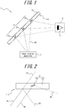
FIG. 1 illustrates an example configuration of an image display system according to a first embodiment; -
FIG. 2 illustrates an example of reflected light and transmitted light corresponding to incident light; -
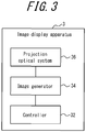
FIG. 3 is a functional block diagram illustrating an example schematic configuration of the image display apparatus inFIG. 1 ; -
FIG. 4 is a plan view illustrating an example configuration of an optical member according to the first embodiment; -
FIG. 5 is a cross-section along the A-A line inFIG. 4 ; -
FIG. 6 illustrates the definition of the inclination angle of a virtual surface; -
FIG. 7 is a flowchart illustrating an example method of manufacturing an optical member; -
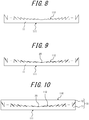
FIG. 8 illustrates an example method of manufacturing an optical member; -
FIG. 9 illustrates an example method of manufacturing an optical member; -
FIG. 10 illustrates an example method of manufacturing an optical member; -
FIG. 11 is a plan view illustrating an example configuration of an optical member according to a second embodiment; and -
FIG. 12 is a cross-section along the B-B line inFIG. 11 . - In head-up displays and other display apparatuses that allow a user to see a virtual image, the range over which the user can see the virtual image is limited if light is specularly reflected by the member on which light is projected. The range over which a virtual image can be seen may correspond to the size of the display apparatus. Demand exists for increasing the range over which a virtual image can be seen with a relatively small display apparatus.
- An image display system 1 (see
FIG. 1 ) according to an embodiment of the present disclosure is described below in detail with reference to the drawings. The drawings referred to below are schematic illustrations. The dimensional ratios and the like in the drawings do not necessarily match the actual dimensions. - As illustrated in
FIG. 1 , theimage display system 1 according to the present embodiment includes anoptical member 2 and animage display apparatus 3. - The
optical member 2 includes asubstrate 10 and a plurality of reflectingsurfaces 20. Thesubstrate 10 includes asubstrate surface 110. Thesubstrate 10 is light-transmissive and transmits at least a portion of light incident on thesubstrate 10. Thesubstrate 10 may be a flat plate. Thesubstrate 10 may have a curved surface. Thesubstrate 10 may have any other shape. Thesubstrate 10 may be flexible. At least a portion of thesubstrate 10 may be made of resin. The reflectingsurface 20 reflects at least a portion of light incident on thesubstrate 10. At least a portion of the reflectingsurfaces 20 is inclined with respect to thesubstrate surface 110. At least a portion of the reflectingsurfaces 20 may be made of a material capable of reflecting light incident on thesubstrate 10. At least a portion of the reflectingsurfaces 20 may be made of a metal material, such as aluminum, silver, or chrome. - As illustrated in
FIG. 2 , whenincident light 41 indicated by a solid line is incident on thesubstrate 10, at least a portion of theincident light 41 may be specularly reflected by thesubstrate surface 110 to become reflectedlight 42, indicated by a dashed line. At least a portion of theincident light 41 may be transmitted by thesubstrate 10 to become transmittedlight 43, indicated by a dashed dotted line. - When
incident light 44 indicated by a solid line is incident on the reflectingsurface 20, at least a portion of theincident light 44 may be specularly reflected by the reflectingsurface 20 to become reflectedlight 45, indicated by a dashed line. When the reflectingsurface 20 is inclined relative to thesubstrate surface 110, the reflectedlight 45 proceeds in a different direction than the reflectedlight 42 reflected by thesubstrate surface 110. In other words, thereflected light 45 is reflected in a different direction than the direction of specular reflection relative to thesubstrate surface 110. - As illustrated in
FIG. 1 , theimage display apparatus 3 emitsimage projection light 40, indicated by dashed lines, onto theoptical member 2. At least a portion of theimage projection light 40 can be reflected by theoptical member 2. At least a portion of the reflectedimage projection light 40 can reach a virtually positioned eye box 4. The user of theimage display system 1 can see a projection image, formed by theimage projection light 40, as a virtual image when aneye 5 of the user is located in the eye box 4. The light transmitted through theoptical member 2 can also reach theeye 5 of the user by virtue of thesubstrate 10 being light-transmissive. The user can see the background on the other side of theoptical member 2 in overlap with the virtual image. - As illustrated in
FIG. 3 , theimage display apparatus 3 includes acontroller 32, animage generator 34, and a projectionoptical system 36. - The
controller 32 controls theimage generator 34 to project theimage projection light 40 that forms the projection image. Thecontroller 32 may generate image data pertaining to the projection image on the basis of information acquired from an external apparatus. Thecontroller 32 may acquire image data pertaining to the projection image from an external apparatus. Thecontroller 32 may, for example, be configured by a processor or microcomputer capable of executing application software. - The
controller 32 may include a storage device storing various information, programs for operating the components of theimage display apparatus 3, and the like. The storage device may, for example, be a semiconductor memory. The storage device may function as a working memory of thecontroller 32. Theimage display apparatus 3 may include the storage device as a storage unit. - The
controller 32 may include a communication device for acquiring various information, image data, or the like from an external apparatus. The communication device may, for example, be a communication interface for a local area network (LAN), control area network (CAN), or the like. The communication device may be capable of communicating with an external apparatus in a wired or wireless manner. Theimage display apparatus 3 may include the communication device as a communication unit. - The
image generator 34 may, for example, include a transmissive liquid crystal device such as a liquid crystal display (LCD) or a reflective liquid crystal device such as liquid crystal on silicon (LCOS). Theimage generator 34 may include a mirror device, such as a digital mirror device (DMD), a micro electro mechanical systems (MEMS) mirror, or the like. Theimage generator 34 may include a lamp, a light emission diode (LED), a laser, or the like as a light source. The light source may be used as a backlight of the liquid crystal display. The light source may be used for causing light to be incident on the mirror device. Theimage generator 34 may include a light-emitting device that is an inorganic electro-luminescence (EL) device, an organic EL device, or the like. - The projection
optical system 36 reflects or refracts theimage projection light 40 emitted from theimage generator 34 to project the light onto theoptical member 2. The projectionoptical system 36 may be a reflective optical system that includes convex or concave mirrors. The projectionoptical system 36 may be a refractive optical system that includes convex or concave lenses. The projectionoptical system 36 may be an optical system combining mirrors or lenses. The mirrors or lenses located in the projectionoptical system 36 may have a spherical surface shape in at least a portion thereof. The mirrors or lenses located in the projectionoptical system 36 may have an aspherical surface shape in at least a portion thereof. The mirrors or lenses located in the projectionoptical system 36 may have a surface shape corresponding to the shape of theoptical member 2 in at least a portion thereof. - As illustrated in
FIG. 4 , the plurality of reflectingsurfaces 20 represented by solid circles are distributed on the inside of the surface of thesubstrate 10. Avirtual surface 140 that has a virtual surface shape is located inside thesubstrate 10. As illustrated inFIG. 5 , at least a portion of thevirtual surface 140 is inclined with respect to thesubstrate surface 110. At least a portion of the reflecting surfaces 20 is positioned to correspond to the surface shape of thevirtual surface 140 and is inclined with respect to thesubstrate surface 110. - The
virtual surface 140 may have a surface shape that collects at least a portion of incident light, incident on thevirtual surface 140 from a predetermined direction, in a predetermined region. The predetermined region where light is collected by thevirtual surface 140 is also referred to as a light-collection region. - The
virtual surface 140 may be configured to include a plurality of annular surfaces that surround areference point 50 virtually located on thesubstrate surface 110. At least a portion of the annular surfaces may be configured so that a normal to the annular surface is oriented towards the inside of the ring. Thevirtual surface 140 that includes a plurality of annular surfaces may have convex portions corresponding to ridge lines and concave portions corresponding to valley lines. The cross-sectional shape of thevirtual surface 140 that includes a plurality of annular surfaces may have a sawtooth shape with peaks and valleys. - The reflecting surfaces 20 may be positioned to correspond to an annular surface configured so that a normal thereto is oriented towards the inside of the ring. The reflecting surfaces 20 may be positioned so as not to straddle a peak or valley of the
virtual surface 140. This configuration facilitates control of the direction of light reflected by the reflecting surfaces 20. Ghosts caused by light reflected by the reflectingsurfaces 20 can be suppressed. The reflectingsurface 20 may be smaller in size than the width of the annular surface. This configuration makes the reflectingsurface 20 less likely to straddle a peak or valley of thevirtual surface 140. - The
virtual surface 140 may be configured so that the angle between thevirtual surface 140 and thesubstrate surface 110 sequentially increases in accordance with distance from thereference point 50. In other words, thevirtual surface 140 may be configured so that the angle between thevirtual surface 140 and thesubstrate surface 110 at a location corresponding to afirst point 51 virtually located on thesubstrate surface 110 sequentially increases in correspondence with increased distance between thereference point 50 and thefirst point 51. The angle between thevirtual surface 140 and thesubstrate surface 110 is also referred to as the virtual surface inclination angle 60 (seeFIG. 6 ). The virtualsurface inclination angle 60 may be defined as the angle between anormal vector 110n to thesubstrate surface 110 at thereference point 50 and anormal vector 140n to thevirtual surface 140 corresponding to thefirst point 51, as illustrated inFIG. 6 , for example. The virtualsurface inclination angle 60 may also be defined as the angle between (i) the orthographic projection of thenormal vector 140n onto a reference plane that includes thenormal vector 110n and thefirst point 51 and (ii) thenormal vector 110n. - The
virtual surface 140 may, for example, have a Fresnel shape corresponding to a Fresnel lens. The Fresnel shape has concentric circular grooves centered on thereference point 50. Each groove includes a substantially perpendicular face and an inclined face that has a predetermined width. The inclined face has a greater inclination as the inclined face is farther from thereference point 50. The reflecting surfaces 20 may be located on the inclined faces of the Fresnel shape. If the reflectingsurfaces 20 are positioned on the substantially perpendicular faces, the light reflected by the reflectingsurfaces 20 may produce a moiré pattern. Moiré patterns or ghosts can be suppressed by the reflectingsurfaces 20 being located only on the inclined faces. The reflectingsurface 20 may be smaller in size than the predetermined width of the inclined face. - The
virtual surface 140 may have another light collecting shape, such as a paraboloidal shape. - The
reference point 50 may be determined so that light that is incident on theoptical member 2 and specularly reflected at thereference point 50 is directed towards the light-collection region. - The
optical member 2 according to the present embodiment can reflect at least a portion of incident light in a different direction than the direction of specular reflection by thesubstrate surface 110. - The
optical member 2 according to the present embodiment may, for example, be provided on the front windshield of a moveable body. In this case, light projected onto the front windshield is reflected towards the driver of the moveable body, thereby allowing the driver to see a virtual image over a wider range of the front windshield. The driver can see the scenery in front of the front windshield by virtue of theoptical member 2 being light-transmissive. - The
optical member 2 according to the present embodiment may be provided as a display panel for digital signage. In this case, light projected onto the display panel is reflected in a particular direction, thereby allowing a virtual image to be displayed as an exclusive advertisement for a person at a particular position. Theoptical member 2 may be provided as a cover of a display panel for digital signage. When the display panel of the digital signage is an LCD display or the like, the virtual image can be displayed in overlap on the display content of the display. This configuration allows advertisements to be deployed more effectively. - The
optical member 2 according to the present embodiment may be provided in a show window. In this case, the reflection of light projected onto the show window allows a virtual image to be displayed in overlap with the merchandise exhibited inside the show window. Light projected onto the show window is reflected in a particular direction, allowing content exclusive to a particular position to be displayed when the show window is viewed from the particular position. This configuration allows advertisements to be deployed more effectively. - An example method of manufacturing the
optical member 2 is now described with reference to the flowchart inFIG. 7 . Afirst substrate 11 having afirst surface 111 and asecond surface 112, as illustrated inFIG. 8 , is used in the method of manufacturing according to the present embodiment. Thefirst substrate 11 may be made of resin. Thesecond surface 112 is opposite thefirst surface 111 and includes inclined faces inclined relative to thefirst surface 111. The shape of thesecond surface 112 may correspond to thevirtual surface 140. - As illustrated in
FIG. 9 , a plurality of reflectingsurfaces 20 are formed on a portion of the inclined faces of thesecond surface 112 of the first substrate 11 (step S1 ofFIG. 7 ). The reflecting surfaces 20 may be formed by depositing a material capable of reflecting light. The reflecting surfaces 20 may be formed by depositing a metal material, such as aluminum, silver, or chrome. The reflecting surfaces 20 may be formed by various film deposition methods, such as sputtering, vacuum deposition, or molecular beam epitaxy (MBE). - The reflecting surfaces 20 may be formed by depositing material after placing a mask having a predetermined pattern on the
second surface 112. The mask having a predetermined pattern may have openings through which the deposition material can pass at portions corresponding to the inclined faces of thesecond surface 112. The regions on thesecond surface 112 where the reflectingsurfaces 20 are formed can be controlled by forming the reflecting surfaces 20 on thesecond surface 112 after placement of the mask. This approach can suppress unwanted moiré patterns, ghosts, or the like. - As illustrated in
FIG. 10 , asecond substrate 12 is formed on top of thesecond surface 112 of thefirst substrate 11 and the plurality of reflecting surfaces 20 (step S2 ofFIG. 7 ). This completes the example method of manufacturing theoptical member 2 according to the present embodiment. Thesecond substrate 12 may be made of resin. Thesecond substrate 12 may be formed by packing resin onto thefirst substrate 11. Thesecond substrate 12 may have a shape capable of fitting onto thesecond surface 112 of thefirst substrate 11 and may be adhered onto thesecond surface 112. Thesecond substrate 12 may be made of the same material as thefirst substrate 11. Thesecond substrate 12 may be formed to prevent defects such as gaps or joints between thefirst substrate 11 and thesecond substrate 12. This configuration can suppress the reflection of light between thefirst substrate 11 and thesecond substrate 12. An optical effect, such as the lens power of thesecond surface 112 of thefirst substrate 11, can be suppressed. - A
virtual surface 140 virtually located on theoptical member 2 according to the present embodiment may have a surface shape such that light incident on thesubstrate surface 110 is reflected in a different direction than the direction of specular reflection. As illustrated inFIG. 11 , thevirtual surface 140 may include a plurality of rectangular faces. As illustrated inFIG. 12 , the cross-sectional shape of thevirtual surface 140 may be a sawtooth shape including faces substantially perpendicular to thesubstrate surface 110 and inclined faces inclined at a predetermined angle relative to thesubstrate surface 110. - Reflecting
surfaces 20 may be located on the inclined faces. In this case, light incident on theoptical member 2 can be reflected in a direction different than the direction of spectral reflection with respect to thesubstrate surface 110. - The reflecting surfaces 20 may be positioned to be inclined at a constant angle relative to the
substrate surface 110. This configuration allows control of the direction of light reflected by theoptical member 2. The light whose direction of reflection is controlled by theoptical member 2 according to the present embodiment can reach a wider range. - The
optical member 2 according to the present embodiment may be provided in a display panel for digital signage, a show window, or the like. In this case, a virtual image in overlap with the content that is normally displayed or exhibited can be displayed in correspondence with the direction in which the digital signage, show window, or the like is viewed. Information can be provided more effectively by a virtual image being overlapped with the content of digital signage or a show window in correspondence with the viewing direction. - The
image display system 1 according to the first and second embodiments can be implemented in a variety of devices. Theimage display system 1 may be implemented in a moveable body, a digital signage system, or a show window production system. Theimage display system 1 may also be implemented as a projection system. Theimage display apparatus 3 may, for example, be implemented as a projector. - The
optical member 2 according to the first and second embodiments may be formed as a film substrate. This configuration allows theoptical member 2 to be mounted onto a curved surface such as glass or a wall. - The term "moveable body" in the present disclosure includes vehicles, ships, and aircraft. The term "vehicle" in the present disclosure includes, but is not limited to, automobiles and industrial vehicles and may also include railway vehicles, vehicles for daily life, and fixed-wing aircraft that run on a runway. Automobiles include, but are not limited to, passenger vehicles, trucks, buses, motorcycles, and trolley buses, and may include other vehicles that travel on the road. Industrial vehicles include industrial vehicles for agriculture and for construction. Industrial vehicles include, but are not limited to, forklifts and golf carts. Industrial vehicles for agriculture include, but are not limited to, tractors, cultivators, transplanters, binders, combines, and lawnmowers. Industrial vehicles for construction include, but are not limited to, bulldozers, scrapers, backhoes, cranes, dump cars, and road rollers. The term "vehicle" includes human-powered vehicles. The vehicle is not limited to the above-listed types. For example, automobiles may include industrial vehicles that can drive on the road, and the same vehicle may be included in multiple categories. The term "ship" in the present disclosure includes marine jets, boats, and tankers. The term "aircraft" in the present disclosure includes fixed-wing aircraft and rotorcraft.
- Configurations according to the present disclosure are not limited to the above embodiments, and a variety of modifications and changes are possible. For example, the functions and the like included in the various components may be reordered in any logically consistent way. Furthermore, components may be combined into one or divided.
-
- 1
- Image display system
- 2
- Optical member
- 3
- Image display apparatus
- 4
- Eye box
- 5
- Eye of user
- 10
- Substrate
- 11
- First substrate
- 12
- Second substrate
- 20
- Reflecting surface
- 32
- Controller
- 34
- Image generator
- 36
- Projection optical system
- 41, 44
- Incident light
- 42, 45
- Reflected light
- 43
- Transmitted light
- 50
- Reference point
- 51
- First point
- 60
- Inclination angle of virtual surface
- 110
- Substrate surface
- 111
- First surface
- 112
- Second surface
- 110n
- Normal vector to substrate surface
- 140
- Virtual surface
- 140n
- Normal vector to virtual surface
Claims (15)
- An optical member comprising:a light-transmissive substrate including a substrate surface; anda plurality of reflecting surfaces located inside the substrate and configured to reflect at least a portion of incident light;wherein at least a portion of the plurality of reflecting surfaces is inclined at a predetermined angle relative to the substrate surface so as to collect at least a portion of the incident light.
- The optical member of claim 1, wherein an inclination of each of the plurality of reflecting surfaces relative to the substrate surface corresponds to a virtual surface shape inside the substrate.
- The optical member of claim 2, wherein the virtual surface shape is a Fresnel shape.
- The optical member of claim 3, wherein each of the plurality of reflecting surface is smaller than a width of an inclined face of the Fresnel shape.
- The optical member of claim 1, wherein an inclination of each of the plurality of reflecting surfaces relative to the substrate surface corresponds to a virtual surface shape inside the substrate, and the virtual surface shape is configured to reflect at least a portion of the incident light in a predetermined direction.
- The optical member of any one of claims 1 to 5, wherein at least a portion of the substrate is made of resin.
- A method of manufacturing an optical member, the method comprising:forming a plurality of reflecting surfaces, on an inclined face of a light-transmissive first substrate including a first surface and a second surface, the second surface being opposite to the first surface and including the inclined face, which is inclined relative to the first surface, wherein the plurality of reflecting surfaces are configured to reflect at least a portion of incident light and at least a portion of the plurality of reflecting surfaces are inclined at a predetermined angle relative to the first surface so as to collect at least a portion of the incident light; andforming a second substrate on top of the second surface of the first substrate and the plurality of reflecting surfaces.
- The method of manufacturing an optical member of claim 7, further wherein the plurality of reflecting surfaces is formed by placing a mask having a predetermined pattern on the second surface and depositing a material to form the reflecting surfaces on a portion of the inclined face.
- The method of manufacturing an optical member of claim 7 or 8, wherein the second substrate is made of the same material as the first substrate.
- An image display system comprising:an optical member comprising:a light-transmissive substrate including a substrate surface; anda plurality of reflecting surfaces located inside the substrate and configured to reflect at least a portion of incident light; andan image display apparatus configured to emit image projection light onto the optical member to display a virtual image;wherein at least a portion of the plurality of reflecting surfaces is inclined at a predetermined angle relative to the substrate surface so as to collect at least a portion of the incident light.
- The image display system of claim 10, wherein an inclination of each of the plurality of reflecting surfaces relative to the substrate surface corresponds to a virtual surface shape inside the substrate, and the virtual surface shape is configured to collect at least a portion of the incident light.
- The image display system of claim 11, wherein the virtual surface shape is a Fresnel shape.
- The image display system of claim 12, wherein each of the plurality of reflecting surface is smaller than a width of an inclined face of the Fresnel shape.
- The image display system of claim 10, wherein an inclination of each of the plurality of reflecting surfaces relative to the substrate surface corresponds to a virtual surface shape inside the substrate, and the virtual surface shape is configured to reflect at least a portion of the incident light in a predetermined direction.
- The image display system of any one of claims 10 to 14, wherein at least a portion of the substrate is made of resin.
Applications Claiming Priority (2)
| Application Number | Priority Date | Filing Date | Title |
|---|---|---|---|
| JP2016167400 | 2016-08-29 | ||
| PCT/JP2017/029948 WO2018043210A1 (en) | 2016-08-29 | 2017-08-22 | Optical member, method for manufacturing optical member, and image display system |
Publications (2)
| Publication Number | Publication Date |
|---|---|
| EP3505980A1 true EP3505980A1 (en) | 2019-07-03 |
| EP3505980A4 EP3505980A4 (en) | 2020-04-15 |
Family
ID=61300687
Family Applications (1)
| Application Number | Title | Priority Date | Filing Date |
|---|---|---|---|
| EP17846215.6A Ceased EP3505980A4 (en) | 2016-08-29 | 2017-08-22 | OPTICAL ELEMENT, METHOD FOR PRODUCING AN OPTICAL ELEMENT, AND IMAGE DISPLAY SYSTEM |
Country Status (4)
| Country | Link |
|---|---|
| US (1) | US11448805B2 (en) |
| EP (1) | EP3505980A4 (en) |
| JP (1) | JPWO2018043210A1 (en) |
| WO (1) | WO2018043210A1 (en) |
Cited By (1)
| Publication number | Priority date | Publication date | Assignee | Title |
|---|---|---|---|---|
| CN112782849A (en) * | 2019-11-08 | 2021-05-11 | 樊茂 | Near-to-eye display system and method |
Families Citing this family (3)
| Publication number | Priority date | Publication date | Assignee | Title |
|---|---|---|---|---|
| US11163163B2 (en) * | 2017-07-03 | 2021-11-02 | Holovisions | Augmented reality (AR) eyewear with at least one quasi Fresnel reflector (QFR) |
| CN111157541B (en) * | 2020-01-14 | 2023-03-14 | 合肥维信诺科技有限公司 | Optical detection system and optical detection method |
| KR20260039706A (en) * | 2023-07-21 | 2026-03-20 | 하만인터내셔날인더스트리스인코포레이티드 | Display equipped with a reflective film |
Family Cites Families (15)
| Publication number | Priority date | Publication date | Assignee | Title |
|---|---|---|---|---|
| US4385430A (en) * | 1980-08-11 | 1983-05-31 | Spectrolab, Inc. | Method of forming an energy concentrator |
| US5321779A (en) * | 1992-11-06 | 1994-06-14 | The Charles Stark Draper Laboratory, Inc. | Optical substrate with light absorbing segments |
| GB2364789A (en) * | 2000-07-14 | 2002-02-06 | Sharp Kk | A transflector |
| TWI230002B (en) * | 2000-10-17 | 2005-03-21 | Nissha Printing | Antireflective molded product and its manufacture method, mold for antireflective molded product |
| US20030035231A1 (en) * | 2001-08-03 | 2003-02-20 | Epstein Kenneth A. | Optical film having microreplicated structures; and methods |
| JP2005003918A (en) | 2003-06-11 | 2005-01-06 | Calsonic Kansei Corp | Head-up display |
| US7656585B1 (en) * | 2008-08-19 | 2010-02-02 | Microvision, Inc. | Embedded relay lens for head-up displays or the like |
| WO2011140199A1 (en) * | 2010-05-04 | 2011-11-10 | University Of South Carolina | Detecting heat capacity changes due to surface inconsistencies using high absorbance spectral regions in the mid-ir |
| JP2013152305A (en) * | 2012-01-24 | 2013-08-08 | Dainippon Printing Co Ltd | Method for manufacturing reflection screen, reflection screen, and image display system |
| US20130229712A1 (en) * | 2012-03-02 | 2013-09-05 | Google Inc. | Sandwiched diffractive optical combiner |
| KR20140019608A (en) * | 2012-08-06 | 2014-02-17 | 삼성전자주식회사 | Screen for front projection apparatus and fabricating method thereof |
| WO2014041691A1 (en) * | 2012-09-14 | 2014-03-20 | パイオニア株式会社 | Optical element and heads-up display |
| JP2015161732A (en) | 2014-02-26 | 2015-09-07 | 矢崎総業株式会社 | Display light projection optical device |
| KR102255145B1 (en) | 2014-12-04 | 2021-05-21 | 다이니폰 인사츠 가부시키가이샤 | Semi-transmissive reflective sheet, light guide plate, and display device |
| JP6652375B2 (en) * | 2015-11-30 | 2020-02-19 | 矢崎総業株式会社 | Display reflector, display light projection optical system, and windshield manufacturing method |
-
2017
- 2017-08-22 EP EP17846215.6A patent/EP3505980A4/en not_active Ceased
- 2017-08-22 JP JP2018537160A patent/JPWO2018043210A1/en active Pending
- 2017-08-22 WO PCT/JP2017/029948 patent/WO2018043210A1/en not_active Ceased
- 2017-08-22 US US16/328,593 patent/US11448805B2/en active Active
Cited By (1)
| Publication number | Priority date | Publication date | Assignee | Title |
|---|---|---|---|---|
| CN112782849A (en) * | 2019-11-08 | 2021-05-11 | 樊茂 | Near-to-eye display system and method |
Also Published As
| Publication number | Publication date |
|---|---|
| US11448805B2 (en) | 2022-09-20 |
| JPWO2018043210A1 (en) | 2019-06-24 |
| US20190187343A1 (en) | 2019-06-20 |
| EP3505980A4 (en) | 2020-04-15 |
| WO2018043210A1 (en) | 2018-03-08 |
Similar Documents
| Publication | Publication Date | Title |
|---|---|---|
| US10859826B2 (en) | Head-up display device | |
| JP7397925B2 (en) | Vehicle information display device and vehicle information display system | |
| EP3919961B1 (en) | Head-up display device | |
| US10302939B2 (en) | Projection device and head-up display device | |
| US20250222767A1 (en) | Information display system and vehicle information display system using the same | |
| US11448805B2 (en) | Optical member, method of manufacturing optical member, and image display system | |
| US10866414B2 (en) | System with holographic head-up display | |
| EP3943331B1 (en) | Head-up display for vehicles and head-up display system for vehicles | |
| US8773329B2 (en) | Head-up display device | |
| KR102192933B1 (en) | Virtual image display device, intermediate image forming unit, and image display light generating unit | |
| JP2017146337A (en) | Aerial graphic display device | |
| CN113103955A (en) | Multi-level imaging system | |
| JP2018097258A (en) | In-vehicle display device | |
| EP3961291B1 (en) | Vehicular head-up display and light source unit used therefor | |
| US20220091417A1 (en) | Head-up display | |
| JP2000241748A (en) | Information display device | |
| JP7591204B2 (en) | Projection system and observation aid | |
| JP7516868B2 (en) | Head-up display | |
| JP2017044926A (en) | Mirror unit | |
| US20180231773A1 (en) | Display system for a windshield and method for configuring the display system | |
| US20180321490A1 (en) | Head up display with facetted windshield | |
| JP6733151B2 (en) | Display device | |
| JP2021081556A (en) | Optical element and manufacturing method therefor | |
| JP7491156B2 (en) | Head-up display device | |
| JP2020020955A (en) | Lighting system, display system, and moving object |
Legal Events
| Date | Code | Title | Description |
|---|---|---|---|
| STAA | Information on the status of an ep patent application or granted ep patent |
Free format text: STATUS: THE INTERNATIONAL PUBLICATION HAS BEEN MADE |
|
| PUAI | Public reference made under article 153(3) epc to a published international application that has entered the european phase |
Free format text: ORIGINAL CODE: 0009012 |
|
| STAA | Information on the status of an ep patent application or granted ep patent |
Free format text: STATUS: REQUEST FOR EXAMINATION WAS MADE |
|
| 17P | Request for examination filed |
Effective date: 20190221 |
|
| AK | Designated contracting states |
Kind code of ref document: A1 Designated state(s): AL AT BE BG CH CY CZ DE DK EE ES FI FR GB GR HR HU IE IS IT LI LT LU LV MC MK MT NL NO PL PT RO RS SE SI SK SM TR |
|
| AX | Request for extension of the european patent |
Extension state: BA ME |
|
| DAV | Request for validation of the european patent (deleted) | ||
| DAX | Request for extension of the european patent (deleted) | ||
| A4 | Supplementary search report drawn up and despatched |
Effective date: 20200312 |
|
| RIC1 | Information provided on ipc code assigned before grant |
Ipc: G02B 5/18 20060101ALI20200306BHEP Ipc: G02B 27/00 20060101ALI20200306BHEP Ipc: G02B 27/01 20060101ALI20200306BHEP Ipc: G09F 9/00 20060101ALI20200306BHEP Ipc: G02B 5/09 20060101AFI20200306BHEP Ipc: G02B 5/08 20060101ALI20200306BHEP |
|
| STAA | Information on the status of an ep patent application or granted ep patent |
Free format text: STATUS: EXAMINATION IS IN PROGRESS |
|
| 17Q | First examination report despatched |
Effective date: 20220404 |
|
| P01 | Opt-out of the competence of the unified patent court (upc) registered |
Effective date: 20230505 |
|
| REG | Reference to a national code |
Ref country code: DE Ref legal event code: R003 |
|
| STAA | Information on the status of an ep patent application or granted ep patent |
Free format text: STATUS: THE APPLICATION HAS BEEN REFUSED |
|
| 18R | Application refused |
Effective date: 20241007 |