EP3505970A1 - An afterglow testing device and an afterglow testing method for a scintillator - Google Patents
An afterglow testing device and an afterglow testing method for a scintillator Download PDFInfo
- Publication number
- EP3505970A1 EP3505970A1 EP18214742.1A EP18214742A EP3505970A1 EP 3505970 A1 EP3505970 A1 EP 3505970A1 EP 18214742 A EP18214742 A EP 18214742A EP 3505970 A1 EP3505970 A1 EP 3505970A1
- Authority
- EP
- European Patent Office
- Prior art keywords
- afterglow
- scintillator
- rotating body
- segment
- testing device
- Prior art date
- Legal status (The legal status is an assumption and is not a legal conclusion. Google has not performed a legal analysis and makes no representation as to the accuracy of the status listed.)
- Withdrawn
Links
Images


Classifications
-
- G—PHYSICS
- G01—MEASURING; TESTING
- G01T—MEASUREMENT OF NUCLEAR OR X-RADIATION
- G01T1/00—Measuring X-radiation, gamma radiation, corpuscular radiation, or cosmic radiation
- G01T1/16—Measuring radiation intensity
- G01T1/20—Measuring radiation intensity with scintillation detectors
-
- G—PHYSICS
- G01—MEASURING; TESTING
- G01T—MEASUREMENT OF NUCLEAR OR X-RADIATION
- G01T7/00—Details of radiation-measuring instruments
-
- G—PHYSICS
- G01—MEASURING; TESTING
- G01N—INVESTIGATING OR ANALYSING MATERIALS BY DETERMINING THEIR CHEMICAL OR PHYSICAL PROPERTIES
- G01N23/00—Investigating or analysing materials by the use of wave or particle radiation, e.g. X-rays or neutrons, not covered by groups G01N3/00 – G01N17/00, G01N21/00 or G01N22/00
- G01N23/02—Investigating or analysing materials by the use of wave or particle radiation, e.g. X-rays or neutrons, not covered by groups G01N3/00 – G01N17/00, G01N21/00 or G01N22/00 by transmitting the radiation through the material
- G01N23/04—Investigating or analysing materials by the use of wave or particle radiation, e.g. X-rays or neutrons, not covered by groups G01N3/00 – G01N17/00, G01N21/00 or G01N22/00 by transmitting the radiation through the material and forming images of the material
-
- G—PHYSICS
- G21—NUCLEAR PHYSICS; NUCLEAR ENGINEERING
- G21K—HANDLING OF PARTICLES OR IONISING RADIATION NOT OTHERWISE PROVIDED FOR; IRRADIATION DEVICES; GAMMA RAY OR X-RAY MICROSCOPES
- G21K1/00—Arrangements for handling particles or ionising radiation, e.g. focusing or moderating
- G21K1/02—Arrangements for handling particles or ionising radiation, e.g. focusing or moderating using diaphragms, collimators
- G21K1/04—Arrangements for handling particles or ionising radiation, e.g. focusing or moderating using diaphragms, collimators using variable diaphragms, shutters, choppers
- G21K1/043—Arrangements for handling particles or ionising radiation, e.g. focusing or moderating using diaphragms, collimators using variable diaphragms, shutters, choppers changing time structure of beams by mechanical means, e.g. choppers, spinning filter wheels
-
- H—ELECTRICITY
- H01—ELECTRIC ELEMENTS
- H01J—ELECTRIC DISCHARGE TUBES OR DISCHARGE LAMPS
- H01J2237/00—Discharge tubes exposing object to beam, e.g. for analysis treatment, etching, imaging
- H01J2237/244—Detection characterized by the detecting means
- H01J2237/2443—Scintillation detectors
Definitions
- the present invention is based on the CN application No. 201711428826.8 with the application date December 26, 2017, and claims priority thereof, and the disclosure of the CN application is hereby incorporated in the present application in its entirety.
- the present invention relates to the field of ray detection, in particular to an afterglow testing device and an afterglow testing method for a scintillator.
- the afterglow problem of detectors made of cesium iodide crystals is relatively serious, especially for image penetration indicators.
- the afterglow needs to be removed from the image data during actual use. So, it is necessary to accurately test the afterglow data of the cesium iodide crystals.
- the afterglow testing device usually uses a belt to drive a steel plate to simulate a process in which an optical machine is quickly turned off.
- the inventors find through analysis that the start and stop of the steel plate driven by the belt have acceleration and deceleration. Therefore, the stability of the steel plate during the moving process is insufficient, resulting in deviation in each test, which leads to inaccurate afterglow test data.
- the present invention provides an afterglow testing device for a scintillator for improving the accuracy of an afterglow test.
- the present invention provides an afterglow testing device for a scintillator, comprising a ray generator, a rotating body and an afterglow detector, wherein the rotating body is configured to be between the ray generator and the scintillator to be tested and is provided with an exit hole which allows rays to pass through, the rotating body for rotating at a constant speed relative to the ray generator to achieve on-off of ray irradiation on the scintillator to be tested, and the afterglow detector for receiving the afterglow of the scintillator to be tested.
- the rotating body comprises a columnar rotating body rotatable about its axis.
- the exit hole comprises an elongated hole that passes through the axis of the columnar rotating body and extends in the diameter direction of the columnar rotating body.
- the vertical-sectional area of the elongated hole is constant.
- the elongated hole is provided with a first segment and a second segment that are respectively arranged on two sides of the axis of the columnar rotating body, and rays successively pass through the first segment and the second segment to illuminate the scintillator to be tested, wherein from the axis of the columnar rotating body to the radial outer side, the vertical-sectional area of the first segment is constant, and the vertical-sectional area of the second segment is gradually increased; or from the axis of the columnar rotating body to the radial outer side, the vertical-sectional areas of both the first segment and the second segment are gradually increased.
- the vertical-sectional areas of both the first segment and the second segment are gradually increased, and the cross sections of the first segment and the second segment are sector-shaped.
- one end of the second segment close to the first segment is smoothly transmitted to the first segment.
- the vertical sectional shape of the elongated hole is polygon.
- the afterglow testing device further comprises a motor for driving the rotating body to rotate.
- the afterglow testing device comprises a data processing device, which calculates the afterglow data of the scintillator to be detected according to the afterglow received by the afterglow detector.
- the density of the rotating body is greater than 16g/cm3.
- the present invention further provides an afterglow testing method for a scintillator, comprising:
- the obtaining and calculating the afterglow data of the scintillator to be tested comprises:
- the afterglow testing device for the scintillator comprises a ray generator, a rotating body and an afterglow detector, wherein the rotating body is arranged between the ray generator and a scintillator to be tested and is provided with an exit hole which allows rays to pass through, the rotating body rotates at a constant speed relative to the ray generator to achieve on-off of ray irradiation on the scintillator to be tested, and the afterglow detector is used for receiving the afterglow of the scintillator to be tested.
- the afterglow testing device of the present invention performs on-off of rays received by the scintillator to be detected by controlling the rotating body to rotate at a constant speed, thereby increasing the stability of the test. Moreover, the rotating body rotates at a constant speed to allow the rays emitted by the ray generator to pass through the exit hole at intervals to illuminate the scintillator at intervals, thereby facilitating multiple tests on the afterglow of the scintillator and improving the accuracy of the afterglow test.
- 1-ray generator 2-rotating body; 21-elongated hole; 211-first segment; 212-second segment; B-test object; A-scintillator.
- spatially relative terms such as “above", “on", “on the upper surface" and “upper” may be used here to describe the spatial positional relationship of one device or feature shown in the drawings with other devices or features. It should be understood that the spatially relative terms are intended to encompass different orientations in use or operation besides the orientations of the devices described in the drawings. For example, if a device in the drawings is inverted, the device described as “above other device or structure” or “on other device or structure” will be positioned “below other device or structure” or “under other device or structure”. Thus, the exemplary term “above" may include both “above" and "below". The device may also be positioned in other different ways (rotated 90 degrees or in other orientations) and the corresponding description of the space used herein is explained accordingly.
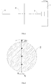
- an afterglow testing device for a scintillator includes a ray generator 1, a rotating body 2 and an afterglow detector (not shown).
- the rotating body 2 is arranged between the ray generator 1 and a scintillator A to be tested and is provided with an exit hole which allows rays to pass through.
- the rotating body 2 rotates at a constant speed relative to the ray generator 1 to control opening and closing on rays received by the scintillator to be tested, and the afterglow detector is used for receiving the afterglow of the scintillator to be tested.
- the afterglow testing device controls the rotation of the rotating body 2 to control opening and closing on rays received by the scintillator to be tested, thereby increasing the stability of the test. Moreover, the rotating body 2 rotates at a constant speed to allow the rays emitted by the ray generator to pass through the exit hole at intervals to illuminate the scintillator at intervals, thereby facilitating multiple tests on the afterglow of the scintillator and improving the accuracy of the afterglow test.
- the afterglow testing device of this embodiment includes a data processing device, which calculates the afterglow data of the scintillator to be detected according to the afterglow received by the afterglow detector.
- the data processing device can perform cumulative correction on the multiple groups of afterglow test data, thereby improving the accuracy of the afterglow test data.
- the data processing device can be provided separately, or the data processing device is integrated into the afterglow detector, and the afterglow detector can directly process the received afterglow signals.
- the afterglow testing device of this embodiment further includes a test object B arranged between the rotating body 2 and the scintillator A to simulate a real scene when the scintillator is used for the detector.
- the afterglow testing device of this embodiment further includes a sample holder for mounting the scintillator A.
- the detector equipped with the scintillator A is directly used for testing.
- the afterglow testing device of this embodiment can be used to test the afterglow of crystals of cesium iodide and the like.
- the rotating body 2 includes a columnar rotating body.
- the columnar rotating body rotates about its axis.
- the exit hole formed in the columnar rotating body can open and close rays.
- the rotating body of this embodiment is made of a high-density material, for example, a material such as tungsten alloy or tantalum having the density of greater than 16 g/cm3.
- the exit hole of this embodiment includes an elongated hole 21 that passes through the axis of the columnar rotating body and extends in the diameter direction of the columnar rotating body.
- the opening size of the elongated hole 21 is constant.
- the vertical-sectional area of the elongated hole is constant.
- the width "a" of the elongated hole should be sufficient for the rays X to map and cover all the scintillator to be tested.
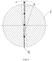
- FIG. 3 exemplarily shows that the rotating body 2 is rotated counterclockwise to achieve on-off control of the rays X.
- the rays X can be irradiated onto the scintillator through a shadow area S.
- the rotating body can completely close the rays to improve the interference of energy deposition on the scintillator to the afterglow test, as shown in FIGS.
- the elongated hole 21 is provided with a first segment 211 and a second segment 212 that are separately arranged on two sides of the axis of the columnar rotating body, and the rays X successively pass through the first segment 211 and the second segment 212 to illuminate the scintillator to be tested.
- the vertical-sectional area of the first segment 211 is constant, while the vertical-sectional area of the second segment 212 is gradually enlarged from the axis of the columnar rotating body to the radial outer side.
- the width of the first segment 211 is "a”.
- the second segment 212 has a minimum width "a” and a maximum width "b". The width "a” is large enough to ensure that the rays X map and cover all the scintillator to be tested.
- the rotating body can be controlled to perform single repeated tests, which can significantly reduce the interference of the energy deposition to the afterglow test when the rays pass through the shadow area.
- the vertical-sectional area of the first segment and the second segment are gradually enlarged from the axis of the columnar rotating body to the radial outer side.
- such arrangement can eliminate the interference of the energy deposition of the rays X passing through the shadow area on the scintillator to the afterglow test.
- the afterglow testing device of this embodiment facilitates superposition of multiple times of signals, increases the signal to noise ratio, and improves the accuracy of the afterglow test.
- first segment and the second segment are arranged symmetrically.
- the cross sections of the first segment and the second segment are sector-shaped.
- one end of the second segment close to the first segment is smoothly transmitted to the first segment.
- the vertical sectional shape of the elongated hole is polygon.
- the vertical sectional shape of the hole is quadrilateral.
- the above-mentioned rotating body of this embodiment can also directly serve as a collimator for detector test, and the exit hole directly serves as a slit for emitting rays by the collimator to define a range of ray radiation.
- the afterglow testing device of this embodiment can be used not only to test the afterglow of the scintillator to grade the afterglow of the scintillator, but also can be directly used in inspection equipment to eliminate the interference of the afterglow on the image.
- the ray generator of this embodiment is an X-ray machine that generates X rays.
- the ray generator can also be a generator that emits other rays.
- the obtaining and calculating the afterglow data of the scintillator(A) to be tested comprises:
- the afterglow testing device for the scintillator has at least the following advantages:
- the rotating body rotates at a constant speed to improve the stability of the test.
- the rotating body is rotated to achieve on-off control of the rays to facilitate the processing of the afterglow data by cumulatively correcting the error by multiple tests, thereby improving the accuracy of the afterglow test.
Landscapes
- Physics & Mathematics (AREA)
- Health & Medical Sciences (AREA)
- Life Sciences & Earth Sciences (AREA)
- General Physics & Mathematics (AREA)
- High Energy & Nuclear Physics (AREA)
- Molecular Biology (AREA)
- Spectroscopy & Molecular Physics (AREA)
- Chemical & Material Sciences (AREA)
- Analytical Chemistry (AREA)
- Biochemistry (AREA)
- General Health & Medical Sciences (AREA)
- Immunology (AREA)
- Pathology (AREA)
- Measurement Of Radiation (AREA)
- Analysing Materials By The Use Of Radiation (AREA)
Abstract
Description
- The present invention is based on the
CN application No. 201711428826.8 - The present invention relates to the field of ray detection, in particular to an afterglow testing device and an afterglow testing method for a scintillator.
- In detector products based on x-ray machines, the afterglow problem of detectors made of cesium iodide crystals is relatively serious, especially for image penetration indicators. In order to improve the accuracy of the image penetration indicators, the afterglow needs to be removed from the image data during actual use. So, it is necessary to accurately test the afterglow data of the cesium iodide crystals.
- In the prior art, the afterglow testing device usually uses a belt to drive a steel plate to simulate a process in which an optical machine is quickly turned off. The inventors find through analysis that the start and stop of the steel plate driven by the belt have acceleration and deceleration. Therefore, the stability of the steel plate during the moving process is insufficient, resulting in deviation in each test, which leads to inaccurate afterglow test data.
- The present invention provides an afterglow testing device for a scintillator for improving the accuracy of an afterglow test.
- The present invention provides an afterglow testing device for a scintillator, comprising a ray generator, a rotating body and an afterglow detector, wherein the rotating body is configured to be between the ray generator and the scintillator to be tested and is provided with an exit hole which allows rays to pass through, the rotating body for rotating at a constant speed relative to the ray generator to achieve on-off of ray irradiation on the scintillator to be tested, and the afterglow detector for receiving the afterglow of the scintillator to be tested.
- In some embodiments, the rotating body comprises a columnar rotating body rotatable about its axis.
- In some embodiments, the exit hole comprises an elongated hole that passes through the axis of the columnar rotating body and extends in the diameter direction of the columnar rotating body.
- In some embodiments, the vertical-sectional area of the elongated hole is constant.
- In some embodiments, the elongated hole is provided with a first segment and a second segment that are respectively arranged on two sides of the axis of the columnar rotating body, and rays successively pass through the first segment and the second segment to illuminate the scintillator to be tested, wherein from the axis of the columnar rotating body to the radial outer side, the vertical-sectional area of the first segment is constant, and the vertical-sectional area of the second segment is gradually increased; or from the axis of the columnar rotating body to the radial outer side, the vertical-sectional areas of both the first segment and the second segment are gradually increased.
- In some embodiments, from the axis of the columnar rotating body to the radial outer side, the vertical-sectional areas of both the first segment and the second segment are gradually increased, and the cross sections of the first segment and the second segment are sector-shaped.
- In some embodiments, one end of the second segment close to the first segment is smoothly transmitted to the first segment.
- In some embodiments, the vertical sectional shape of the elongated hole is polygon.
- In some embodiments, the afterglow testing device further comprises a motor for driving the rotating body to rotate.
- In some embodiments, the afterglow testing device comprises a data processing device, which calculates the afterglow data of the scintillator to be detected according to the afterglow received by the afterglow detector.
- In some embodiments, the density of the rotating body is greater than 16g/cm3.
- The present invention further provides an afterglow testing method for a scintillator, comprising:
- placing a rotating body between the ray generator and the scintillator to be tested;
- make the rotating body rotate at a constant speed to achieve on-off of ray irradiation on the scintillator to be tested;
- obtaining and calculating the afterglow data of the scintillator to be tested.
- In some embodiments, the obtaining and calculating the afterglow data of the scintillator to be tested comprises:
- obtaining multiple groups of the afterglow data;
- cumulative correction of the multiple groups of the afterglow data is made.
- The afterglow testing device for the scintillator according to the present invention comprises a ray generator, a rotating body and an afterglow detector, wherein the rotating body is arranged between the ray generator and a scintillator to be tested and is provided with an exit hole which allows rays to pass through, the rotating body rotates at a constant speed relative to the ray generator to achieve on-off of ray irradiation on the scintillator to be tested, and the afterglow detector is used for receiving the afterglow of the scintillator to be tested. The afterglow testing device of the present invention performs on-off of rays received by the scintillator to be detected by controlling the rotating body to rotate at a constant speed, thereby increasing the stability of the test. Moreover, the rotating body rotates at a constant speed to allow the rays emitted by the ray generator to pass through the exit hole at intervals to illuminate the scintillator at intervals, thereby facilitating multiple tests on the afterglow of the scintillator and improving the accuracy of the afterglow test.
- Other features of the present invention and the advantages thereof will become apparent through the following detailed descriptions of exemplary embodiments of the present invention with reference to the accompanying drawings.
- The accompanying drawings described here are used for providing a further understanding on the present invention, and constitute a part of the present application. The schematic embodiments of the present invention and the descriptions thereof are used for interpreting the present invention, rather than constituting improper limitations to the present invention. In the drawings:
-
FIG. 1 is a structure diagram of an afterglow testing device for a scintillator according to the present invention; -
FIG. 2 is a structure diagram of an embodiment of a rotating body inFIG. 1 . -
FIG. 3 is a schematic diagram of a rotating process of the rotating body shown inFIG. 2 ; -
FIG. 4 is a structure diagram of another embodiment of the rotating body inFIG. 1 ; -
FIG. 5 is a structure diagram of another embodiment of the rotating body inFIG. 1 ; -
FIG. 6 is a schematic diagram of a rotating process of the rotating body shown inFIG. 5 . - 1-ray generator; 2-rotating body; 21-elongated hole; 211-first segment; 212-second segment; B-test object; A-scintillator.
- A clear and complete description will be made to the technical solutions in the embodiments of the present invention below in combination with the accompanying drawing in the embodiments of the present invention. Apparently, the embodiments described are only part of the embodiments of the present invention, not all of them. The following description of at least one exemplary embodiment is actually only illustrative, and serves by no means as any limitation to the present invention and an application or usage thereof. All other embodiments obtained by a person of ordinary skill in the art based on the embodiments of the present invention without creative efforts shall fall within the protection scope of the present invention.
- Unless otherwise specified, relative arrangements of parts and steps, expressions of figures and numerical values described in these embodiments do not limit the scope of the present invention. Meanwhile, it should be understood that, in order to facilitate description, the sizes of all parts shown in the drawings are not drawn according to an actual proportional relation. Technologies, methods and devices known by those of ordinary skills in related arts may not be discussed in detail, but in appropriate situations, the technologies, methods and devices should be regarded as part of the specification as granted. In all of the examples shown and discussed here, any specific value should be interpreted as illustrative only but not restrictive. Accordingly, other examples of the exemplary embodiments may have different values. It should be noted that similar reference numerals and letters in the following drawings represent similar terms, so that once a certain term is defined in a drawing, there is no need of further discussing this term in the follow-up drawings.
- For ease of description, spatially relative terms such as "above...", "on...", "on the upper surface..." and "upper..." may be used here to describe the spatial positional relationship of one device or feature shown in the drawings with other devices or features. It should be understood that the spatially relative terms are intended to encompass different orientations in use or operation besides the orientations of the devices described in the drawings. For example, if a device in the drawings is inverted, the device described as "above other device or structure" or "on other device or structure" will be positioned "below other device or structure" or "under other device or structure". Thus, the exemplary term "above..." may include both "above..." and "below...". The device may also be positioned in other different ways (rotated 90 degrees or in other orientations) and the corresponding description of the space used herein is explained accordingly.
- As shown in
FIG. 1 , an afterglow testing device for a scintillator according to an embodiment of the present invention includes aray generator 1, a rotatingbody 2 and an afterglow detector (not shown). Therotating body 2 is arranged between theray generator 1 and a scintillator A to be tested and is provided with an exit hole which allows rays to pass through. Therotating body 2 rotates at a constant speed relative to theray generator 1 to control opening and closing on rays received by the scintillator to be tested, and the afterglow detector is used for receiving the afterglow of the scintillator to be tested. - The afterglow testing device controls the rotation of the
rotating body 2 to control opening and closing on rays received by the scintillator to be tested, thereby increasing the stability of the test. Moreover, therotating body 2 rotates at a constant speed to allow the rays emitted by the ray generator to pass through the exit hole at intervals to illuminate the scintillator at intervals, thereby facilitating multiple tests on the afterglow of the scintillator and improving the accuracy of the afterglow test. - Preferably, the afterglow testing device of this embodiment includes a data processing device, which calculates the afterglow data of the scintillator to be detected according to the afterglow received by the afterglow detector. After the
rotating body 2 rotates at a constant speed to acquire multiple groups of afterglow test data, the data processing device can perform cumulative correction on the multiple groups of afterglow test data, thereby improving the accuracy of the afterglow test data. - The data processing device can be provided separately, or the data processing device is integrated into the afterglow detector, and the afterglow detector can directly process the received afterglow signals.
- As shown in
FIG. 1 , the afterglow testing device of this embodiment further includes a test object B arranged between therotating body 2 and the scintillator A to simulate a real scene when the scintillator is used for the detector. - Preferably, the afterglow testing device of this embodiment further includes a sample holder for mounting the scintillator A.
- Specifically, the detector equipped with the scintillator A is directly used for testing.
- The afterglow testing device of this embodiment can be used to test the afterglow of crystals of cesium iodide and the like.
- The structure of the rotating body according to the specific embodiment of the present invention will be described in detail below according to
FIGS. 2 to 6 . - In this embodiment, the
rotating body 2 includes a columnar rotating body. The columnar rotating body rotates about its axis. When the columnar rotating body rotates about its axis, the exit hole formed in the columnar rotating body can open and close rays. - Preferably, the rotating body of this embodiment is made of a high-density material, for example, a material such as tungsten alloy or tantalum having the density of greater than 16 g/cm3.
- As shown in
FIGS. 2 to 6 , the exit hole of this embodiment includes anelongated hole 21 that passes through the axis of the columnar rotating body and extends in the diameter direction of the columnar rotating body. By such arrangement, rays can illuminate the scintillator at certain time intervals and be closed, thereby facilitating multiple tests on the afterglow and improving the accuracy of the afterglow tests. - In one embodiment, as shown in
FIG. 2 , the opening size of theelongated hole 21 is constant. In other words, the vertical-sectional area of the elongated hole is constant. The width "a" of the elongated hole should be sufficient for the rays X to map and cover all the scintillator to be tested. -
FIG. 3 exemplarily shows that therotating body 2 is rotated counterclockwise to achieve on-off control of the rays X. When therotating body 2 is rotated to immediately close the rays, the rays X can be irradiated onto the scintillator through a shadow area S. In order that the rotating body can completely close the rays to improve the interference of energy deposition on the scintillator to the afterglow test, as shown inFIGS. 4 and5 , in another embodiment, theelongated hole 21 is provided with afirst segment 211 and asecond segment 212 that are separately arranged on two sides of the axis of the columnar rotating body, and the rays X successively pass through thefirst segment 211 and thesecond segment 212 to illuminate the scintillator to be tested. - As shown in
FIG. 4 , in this embodiment, the vertical-sectional area of thefirst segment 211 is constant, while the vertical-sectional area of thesecond segment 212 is gradually enlarged from the axis of the columnar rotating body to the radial outer side. The width of thefirst segment 211 is "a". Thesecond segment 212 has a minimum width "a" and a maximum width "b". The width "a" is large enough to ensure that the rays X map and cover all the scintillator to be tested. - When the afterglow is tested using the rotating body as shown in
FIG. 4 , the rotating body can be controlled to perform single repeated tests, which can significantly reduce the interference of the energy deposition to the afterglow test when the rays pass through the shadow area. - Preferably, as shown in
FIG. 5 , in another embodiment, the vertical-sectional area of the first segment and the second segment are gradually enlarged from the axis of the columnar rotating body to the radial outer side. As shown inFig. 6 , such arrangement can eliminate the interference of the energy deposition of the rays X passing through the shadow area on the scintillator to the afterglow test. Moreover, the afterglow testing device of this embodiment facilitates superposition of multiple times of signals, increases the signal to noise ratio, and improves the accuracy of the afterglow test. - In this embodiment, the first segment and the second segment are arranged symmetrically.
- In this embodiment, the cross sections of the first segment and the second segment are sector-shaped.
- In this embodiment, one end of the second segment close to the first segment is smoothly transmitted to the first segment.
- In this embodiment, the vertical sectional shape of the elongated hole is polygon. Specially, the vertical sectional shape of the hole is quadrilateral.
- In addition, the above-mentioned rotating body of this embodiment can also directly serve as a collimator for detector test, and the exit hole directly serves as a slit for emitting rays by the collimator to define a range of ray radiation. Moreover, the afterglow testing device of this embodiment can be used not only to test the afterglow of the scintillator to grade the afterglow of the scintillator, but also can be directly used in inspection equipment to eliminate the interference of the afterglow on the image.
- The ray generator of this embodiment is an X-ray machine that generates X rays. Of course, the ray generator can also be a generator that emits other rays.
- An afterglow testing method for a scintillator according to an embodiment of the present invention comprises:
- placing a rotating body between the
ray generator 1 and the scintillator A to be tested; - make the rotating body rotate at a constant speed to achieve on-off of ray irradiation on the scintillator A to be tested;
- obtaining and calculating the afterglow data of the scintillator A to be tested.
- In this embodiment, the obtaining and calculating the afterglow data of the scintillator(A) to be tested comprises:
- obtaining multiple groups of the afterglow data;
- cumulative correction of the multiple groups of the afterglow data is made.
- In summary, the afterglow testing device for the scintillator according to this embodiment has at least the following advantages:
- The rotating body rotates at a constant speed to improve the stability of the test.
- The rotating body is rotated to achieve on-off control of the rays to facilitate the processing of the afterglow data by cumulatively correcting the error by multiple tests, thereby improving the accuracy of the afterglow test.
- Finally, it should be noted that the above embodiments are only for explaining, but not limiting, the technical solutions of the present invention. Although the present invention has been described in detail with reference to the preferred embodiments, those of ordinary skill in the art should understood that the specific embodiments of the present invention may still be modified, or part of the technical features may be equivalently substituted without departing from the spirit of the technical solutions of the present invention, and such modifications or substitutions shall fall within the scope of the technical solutions of the present invention.
Claims (13)
- An afterglow testing device for a scintillator, comprising a ray generator (1), a rotating body (2) and an afterglow detector, wherein the rotating body (2) is configured to be between the ray generator (1) and the scintillator (A) to be tested and is provided with an exit hole which allows rays to pass through, the rotating body (2) for rotating at a constant speed relative to the ray generator (1) to achieve on-off of ray irradiation on the scintillator (A) to be tested, and the afterglow detector for receiving the afterglow of the scintillator(A) to be tested.
- The afterglow testing device for a scintillator according to claim 1, wherein the rotating body (2) comprises a columnar rotating body rotatable about its axis.
- The afterglow testing device for a scintillator according to claim 2, wherein the exit hole comprises an elongated hole (21) that passes through the axis of the columnar rotating body and extends in the diameter direction of the columnar rotating body.
- The afterglow testing device for a scintillator according to claim 3, wherein the vertical-sectional area of the elongated hole (21) is constant.
- The afterglow testing device for a scintillator according to claim 3, wherein the elongated hole (21) is provided with a first segment (211) and a second segment (212) that are respectively arranged on two sides of the axis of the columnar rotating body, and rays successively pass through the first segment (211) and the second segment (212) to illuminate the scintillator to be tested, wherein from the axis of the columnar rotating body to the radial outer side, the vertical-sectional area of the first segment (211) is constant, and the vertical-sectional area of the second segment (212) is gradually increased; or from the axis of the columnar rotating body to the radial outer side, the vertical-sectional areas of both the first segment (211) and the second segment (212) are gradually increased.
- The afterglow testing device for a scintillator according to claim 5, wherein from the axis of the columnar rotating body to the radial outer side, the vertical-sectional areas of both the first segment (211) and the second segment (212) are gradually increased, and the cross sections of the first segment (211) and the second segment (212) are sector-shaped.
- The afterglow testing device for a scintillator according to claim 5, wherein one end of the second segment close to the first segment is smoothly transmitted to the first segment.
- The afterglow testing device for a scintillator according to claim 3, wherein the vertical-sectional shape of the elongated hole (21) is polygon.
- The afterglow testing device for a scintillator according to claim 1, further comprising a motor for driving the rotating body to rotate.
- The afterglow testing device for a scintillator according to claim 1, comprising a data processing device, which calculates the afterglow data of the scintillator to be detected according to the afterglow received by the afterglow detector.
- The afterglow testing device for a scintillator according to claim 1, wherein the density of the rotating body (2) is greater than 16g/cm3.
- An afterglow testing method for a scintillator, comprising:placing a rotating body between the ray generator (1) and the scintillator (A) to be tested,;make the rotating body rotate at a constant speed to achieve on-off of ray irradiation on the scintillator (A) to be tested;obtaining and calculating the afterglow data of the scintillator(A) to be tested.
- The afterglow testing method for a scintillator, wherein the obtaining and calculating the afterglow data of the scintillator(A) to be tested comprises:obtaining multiple groups of the afterglow data;cumulative correction of the multiple groups of the afterglow data is made.
Applications Claiming Priority (1)
| Application Number | Priority Date | Filing Date | Title |
|---|---|---|---|
| CN201711428826.8A CN107861146B (en) | 2017-12-26 | 2017-12-26 | Scintillator afterglow test device |
Publications (1)
| Publication Number | Publication Date |
|---|---|
| EP3505970A1 true EP3505970A1 (en) | 2019-07-03 |
Family
ID=61707652
Family Applications (1)
| Application Number | Title | Priority Date | Filing Date |
|---|---|---|---|
| EP18214742.1A Withdrawn EP3505970A1 (en) | 2017-12-26 | 2018-12-20 | An afterglow testing device and an afterglow testing method for a scintillator |
Country Status (3)
| Country | Link |
|---|---|
| EP (1) | EP3505970A1 (en) |
| JP (1) | JP2019117194A (en) |
| CN (1) | CN107861146B (en) |
Families Citing this family (4)
| Publication number | Priority date | Publication date | Assignee | Title |
|---|---|---|---|---|
| CN108535770B (en) * | 2018-05-09 | 2024-01-02 | 同方威视技术股份有限公司 | Afterglow detection device and afterglow detection method |
| CN110609314B (en) * | 2019-10-30 | 2024-07-02 | 北京物资学院 | Afterglow testing device of scintillator |
| CN112034505B (en) * | 2020-08-31 | 2024-08-16 | 中国科学院西安光学精密机械研究所 | Scintillator afterglow accurate measurement device and method |
| CN114296124B (en) * | 2021-12-30 | 2025-01-07 | 上海联影医疗科技股份有限公司 | Scintillator afterglow test system, method, device and electronic equipment |
Citations (1)
| Publication number | Priority date | Publication date | Assignee | Title |
|---|---|---|---|---|
| JPH02213795A (en) * | 1989-02-14 | 1990-08-24 | Shimadzu Corp | Scintillator detector |
Family Cites Families (5)
| Publication number | Priority date | Publication date | Assignee | Title |
|---|---|---|---|---|
| GB1489345A (en) * | 1975-01-16 | 1977-10-19 | Emi Ltd | Apparatus for examining bodies by means of penetrating radiation |
| US5666393A (en) * | 1994-02-17 | 1997-09-09 | Annis; Martin | Method and apparatus for reducing afterglow noise in an X-ray inspection system |
| CN102768219B (en) * | 2012-07-26 | 2014-07-30 | 清华大学 | Combined nondestructive testing method and combined nondestructive testing system |
| CN104198507B (en) * | 2014-09-16 | 2017-06-16 | 北京一体通探测技术有限公司 | Shield the shutter device and ray scanning imaging system of ray |
| CN207851314U (en) * | 2017-12-26 | 2018-09-11 | 同方威视技术股份有限公司 | Afterglow test device for scintillators |
-
2017
- 2017-12-26 CN CN201711428826.8A patent/CN107861146B/en active Active
-
2018
- 2018-12-20 EP EP18214742.1A patent/EP3505970A1/en not_active Withdrawn
- 2018-12-25 JP JP2018240733A patent/JP2019117194A/en active Pending
Patent Citations (1)
| Publication number | Priority date | Publication date | Assignee | Title |
|---|---|---|---|---|
| JPH02213795A (en) * | 1989-02-14 | 1990-08-24 | Shimadzu Corp | Scintillator detector |
Non-Patent Citations (4)
| Title |
|---|
| A LEGRAND ET AL: "An ultrafast mechanical shutter for X-rays", NUCLEAR INSTRUMENTS AND METHODS IN PHYSICS RESEARCH SECTION A: ACCELERATORS, SPECTROMETERS, DETECTORS AND ASSOCIATED EQUIPMENT, vol. 275, no. 2, 15 February 1989 (1989-02-15), pages 442 - 446, XP055001570, ISSN: 0168-9002, DOI: 10.1016/0168-9002(89)90722-5 * |
| C.M. BARTLE ET AL: "Novel methods for measuring afterglow in developmental scintillators for X-ray and neutron detection", NUCLEAR INSTRUMENTS & METHODS IN PHYSICS RESEARCH. SECTION A, vol. 651, no. 1, 12 January 2011 (2011-01-12), NL, pages 105 - 109, XP055573189, ISSN: 0168-9002, DOI: 10.1016/j.nima.2011.01.001 * |
| MOHIT TYAGI ET AL: "Development of a setup for measuring the afterglow of scintillating materials", APPLIED PHYSICS B: LASERS AND OPTICS., vol. 62, 1 January 2017 (2017-01-01), DE, pages 1126 - 1127, XP055573545, ISSN: 0946-2171 * |
| MÜLLER O ET AL: "Hard disk drive based microsecond x-ray chopper for characterization of ionization chambers and photodiodes", REVIEW OF SCIENTIFIC INSTRUMENTS, AIP, MELVILLE, NY, US, vol. 86, no. 3, 1 January 1901 (1901-01-01), XP012195358, ISSN: 0034-6748, [retrieved on 19010101], DOI: 10.1063/1.4913900 * |
Also Published As
| Publication number | Publication date |
|---|---|
| CN107861146A (en) | 2018-03-30 |
| CN107861146B (en) | 2024-05-14 |
| JP2019117194A (en) | 2019-07-18 |
Similar Documents
| Publication | Publication Date | Title |
|---|---|---|
| US12233285B2 (en) | Systems, methods, and devices for radiation beam asymmetry measurements using electronic portal imaging devices | |
| US6542578B2 (en) | Apparatus for determining the crystalline and polycrystalline materials of an item | |
| CN107861146B (en) | Scintillator afterglow test device | |
| EP3182105B1 (en) | Method and system for identifying a liquid | |
| DE4428363A1 (en) | X-ray microdiffractometer | |
| CN106572823A (en) | Projection data acquisition apparatus | |
| EP2394701A1 (en) | Characterization of a source trajectory for radiotherapy | |
| KR20150007877A (en) | Computed tomography system comprising rotatable collimator | |
| US20210003462A1 (en) | X-ray stress measurement device | |
| JP2012183283A (en) | Rotating action verification system, rotating action verification method, program, and recording medium | |
| US20220296181A1 (en) | Rotating collimator for an x-ray detection system | |
| EP3496815B1 (en) | Linac quality control device | |
| KR101997409B1 (en) | Experimental apparatus for radiation shield and the method thereof | |
| CN207851314U (en) | Afterglow test device for scintillators | |
| DE19954664B4 (en) | Device for the determination of crystalline and polycrystalline materials of an article | |
| KR101669220B1 (en) | Apparatus for multi-element analyzing X-ray fluorescence | |
| US10728996B2 (en) | Circular x-ray tube and an x-ray instrument comprising the circular x-ray tube | |
| KR102733332B1 (en) | Radiation sensor calibration device | |
| JPH1144662A (en) | Micro X-ray analyzer | |
| CN117970423A (en) | Collimation device and radioactive waste barrel measurement system | |
| CN110389142A (en) | X-ray analysis device and method | |
| JP3629542B2 (en) | X-ray fluorescence analyzer | |
| US20240359036A1 (en) | Radiotherapy systems and methods for quality assurance and calibration | |
| KR200480761Y1 (en) | Collimator radiographic testing indicators for the effective area | |
| JP3673981B2 (en) | X-ray diffraction quantitative device |
Legal Events
| Date | Code | Title | Description |
|---|---|---|---|
| PUAI | Public reference made under article 153(3) epc to a published international application that has entered the european phase |
Free format text: ORIGINAL CODE: 0009012 |
|
| STAA | Information on the status of an ep patent application or granted ep patent |
Free format text: STATUS: THE APPLICATION HAS BEEN PUBLISHED |
|
| AK | Designated contracting states |
Kind code of ref document: A1 Designated state(s): AL AT BE BG CH CY CZ DE DK EE ES FI FR GB GR HR HU IE IS IT LI LT LU LV MC MK MT NL NO PL PT RO RS SE SI SK SM TR |
|
| AX | Request for extension of the european patent |
Extension state: BA ME |
|
| STAA | Information on the status of an ep patent application or granted ep patent |
Free format text: STATUS: REQUEST FOR EXAMINATION WAS MADE |
|
| 17P | Request for examination filed |
Effective date: 20190917 |
|
| RBV | Designated contracting states (corrected) |
Designated state(s): AL AT BE BG CH CY CZ DE DK EE ES FI FR GB GR HR HU IE IS IT LI LT LU LV MC MK MT NL NO PL PT RO RS SE SI SK SM TR |
|
| STAA | Information on the status of an ep patent application or granted ep patent |
Free format text: STATUS: EXAMINATION IS IN PROGRESS |
|
| 17Q | First examination report despatched |
Effective date: 20200409 |
|
| GRAP | Despatch of communication of intention to grant a patent |
Free format text: ORIGINAL CODE: EPIDOSNIGR1 |
|
| STAA | Information on the status of an ep patent application or granted ep patent |
Free format text: STATUS: GRANT OF PATENT IS INTENDED |
|
| INTG | Intention to grant announced |
Effective date: 20210225 |
|
| STAA | Information on the status of an ep patent application or granted ep patent |
Free format text: STATUS: THE APPLICATION IS DEEMED TO BE WITHDRAWN |
|
| 18D | Application deemed to be withdrawn |
Effective date: 20210701 |