EP3505836A1 - Switching device for multi-split air conditioner and multi-split air conditioner having same - Google Patents
Switching device for multi-split air conditioner and multi-split air conditioner having same Download PDFInfo
- Publication number
- EP3505836A1 EP3505836A1 EP17842642.5A EP17842642A EP3505836A1 EP 3505836 A1 EP3505836 A1 EP 3505836A1 EP 17842642 A EP17842642 A EP 17842642A EP 3505836 A1 EP3505836 A1 EP 3505836A1
- Authority
- EP
- European Patent Office
- Prior art keywords
- indoor
- unit connection
- switching device
- air conditioner
- base
- Prior art date
- Legal status (The legal status is an assumption and is not a legal conclusion. Google has not performed a legal analysis and makes no representation as to the accuracy of the status listed.)
- Withdrawn
Links
Images





Classifications
-
- F—MECHANICAL ENGINEERING; LIGHTING; HEATING; WEAPONS; BLASTING
- F24—HEATING; RANGES; VENTILATING
- F24F—AIR-CONDITIONING; AIR-HUMIDIFICATION; VENTILATION; USE OF AIR CURRENTS FOR SCREENING
- F24F1/00—Room units for air-conditioning, e.g. separate or self-contained units or units receiving primary air from a central station
- F24F1/06—Separate outdoor units, e.g. outdoor unit to be linked to a separate room comprising a compressor and a heat exchanger
- F24F1/26—Refrigerant piping
- F24F1/32—Refrigerant piping for connecting the separate outdoor units to indoor units
-
- F—MECHANICAL ENGINEERING; LIGHTING; HEATING; WEAPONS; BLASTING
- F24—HEATING; RANGES; VENTILATING
- F24F—AIR-CONDITIONING; AIR-HUMIDIFICATION; VENTILATION; USE OF AIR CURRENTS FOR SCREENING
- F24F1/00—Room units for air-conditioning, e.g. separate or self-contained units or units receiving primary air from a central station
- F24F1/06—Separate outdoor units, e.g. outdoor unit to be linked to a separate room comprising a compressor and a heat exchanger
- F24F1/26—Refrigerant piping
- F24F1/34—Protection means thereof, e.g. covers for refrigerant pipes
-
- F—MECHANICAL ENGINEERING; LIGHTING; HEATING; WEAPONS; BLASTING
- F24—HEATING; RANGES; VENTILATING
- F24F—AIR-CONDITIONING; AIR-HUMIDIFICATION; VENTILATION; USE OF AIR CURRENTS FOR SCREENING
- F24F1/00—Room units for air-conditioning, e.g. separate or self-contained units or units receiving primary air from a central station
- F24F1/06—Separate outdoor units, e.g. outdoor unit to be linked to a separate room comprising a compressor and a heat exchanger
- F24F1/36—Drip trays for outdoor units
-
- F—MECHANICAL ENGINEERING; LIGHTING; HEATING; WEAPONS; BLASTING
- F24—HEATING; RANGES; VENTILATING
- F24F—AIR-CONDITIONING; AIR-HUMIDIFICATION; VENTILATION; USE OF AIR CURRENTS FOR SCREENING
- F24F1/00—Room units for air-conditioning, e.g. separate or self-contained units or units receiving primary air from a central station
- F24F1/06—Separate outdoor units, e.g. outdoor unit to be linked to a separate room comprising a compressor and a heat exchanger
- F24F1/40—Vibration or noise prevention at outdoor units
-
- F—MECHANICAL ENGINEERING; LIGHTING; HEATING; WEAPONS; BLASTING
- F24—HEATING; RANGES; VENTILATING
- F24F—AIR-CONDITIONING; AIR-HUMIDIFICATION; VENTILATION; USE OF AIR CURRENTS FOR SCREENING
- F24F11/00—Control or safety arrangements
- F24F11/70—Control systems characterised by their outputs; Constructional details thereof
- F24F11/72—Control systems characterised by their outputs; Constructional details thereof for controlling the supply of treated air, e.g. its pressure
-
- F—MECHANICAL ENGINEERING; LIGHTING; HEATING; WEAPONS; BLASTING
- F24—HEATING; RANGES; VENTILATING
- F24F—AIR-CONDITIONING; AIR-HUMIDIFICATION; VENTILATION; USE OF AIR CURRENTS FOR SCREENING
- F24F11/00—Control or safety arrangements
- F24F11/70—Control systems characterised by their outputs; Constructional details thereof
- F24F11/80—Control systems characterised by their outputs; Constructional details thereof for controlling the temperature of the supplied air
- F24F11/83—Control systems characterised by their outputs; Constructional details thereof for controlling the temperature of the supplied air by controlling the supply of heat-exchange fluids to heat-exchangers
- F24F11/84—Control systems characterised by their outputs; Constructional details thereof for controlling the temperature of the supplied air by controlling the supply of heat-exchange fluids to heat-exchangers using valves
-
- F—MECHANICAL ENGINEERING; LIGHTING; HEATING; WEAPONS; BLASTING
- F24—HEATING; RANGES; VENTILATING
- F24F—AIR-CONDITIONING; AIR-HUMIDIFICATION; VENTILATION; USE OF AIR CURRENTS FOR SCREENING
- F24F13/00—Details common to, or for air-conditioning, air-humidification, ventilation or use of air currents for screening
- F24F13/20—Casings or covers
-
- F—MECHANICAL ENGINEERING; LIGHTING; HEATING; WEAPONS; BLASTING
- F24—HEATING; RANGES; VENTILATING
- F24F—AIR-CONDITIONING; AIR-HUMIDIFICATION; VENTILATION; USE OF AIR CURRENTS FOR SCREENING
- F24F13/00—Details common to, or for air-conditioning, air-humidification, ventilation or use of air currents for screening
- F24F13/24—Means for preventing or suppressing noise
-
- F—MECHANICAL ENGINEERING; LIGHTING; HEATING; WEAPONS; BLASTING
- F25—REFRIGERATION OR COOLING; COMBINED HEATING AND REFRIGERATION SYSTEMS; HEAT PUMP SYSTEMS; MANUFACTURE OR STORAGE OF ICE; LIQUEFACTION SOLIDIFICATION OF GASES
- F25B—REFRIGERATION MACHINES, PLANTS OR SYSTEMS; COMBINED HEATING AND REFRIGERATION SYSTEMS; HEAT PUMP SYSTEMS
- F25B13/00—Compression machines, plants or systems, with reversible cycle
-
- F—MECHANICAL ENGINEERING; LIGHTING; HEATING; WEAPONS; BLASTING
- F24—HEATING; RANGES; VENTILATING
- F24F—AIR-CONDITIONING; AIR-HUMIDIFICATION; VENTILATION; USE OF AIR CURRENTS FOR SCREENING
- F24F1/00—Room units for air-conditioning, e.g. separate or self-contained units or units receiving primary air from a central station
- F24F1/06—Separate outdoor units, e.g. outdoor unit to be linked to a separate room comprising a compressor and a heat exchanger
- F24F1/08—Compressors specially adapted for separate outdoor units
- F24F1/12—Vibration or noise prevention thereof
-
- F—MECHANICAL ENGINEERING; LIGHTING; HEATING; WEAPONS; BLASTING
- F24—HEATING; RANGES; VENTILATING
- F24F—AIR-CONDITIONING; AIR-HUMIDIFICATION; VENTILATION; USE OF AIR CURRENTS FOR SCREENING
- F24F1/00—Room units for air-conditioning, e.g. separate or self-contained units or units receiving primary air from a central station
- F24F1/06—Separate outdoor units, e.g. outdoor unit to be linked to a separate room comprising a compressor and a heat exchanger
- F24F1/56—Casing or covers of separate outdoor units, e.g. fan guards
-
- F—MECHANICAL ENGINEERING; LIGHTING; HEATING; WEAPONS; BLASTING
- F24—HEATING; RANGES; VENTILATING
- F24F—AIR-CONDITIONING; AIR-HUMIDIFICATION; VENTILATION; USE OF AIR CURRENTS FOR SCREENING
- F24F13/00—Details common to, or for air-conditioning, air-humidification, ventilation or use of air currents for screening
- F24F13/24—Means for preventing or suppressing noise
- F24F2013/242—Sound-absorbing material
-
- F—MECHANICAL ENGINEERING; LIGHTING; HEATING; WEAPONS; BLASTING
- F24—HEATING; RANGES; VENTILATING
- F24F—AIR-CONDITIONING; AIR-HUMIDIFICATION; VENTILATION; USE OF AIR CURRENTS FOR SCREENING
- F24F3/00—Air-conditioning systems in which conditioned primary air is supplied from one or more central stations to distributing units in the rooms or spaces where it may receive secondary treatment; Apparatus specially designed for such systems
- F24F3/06—Air-conditioning systems in which conditioned primary air is supplied from one or more central stations to distributing units in the rooms or spaces where it may receive secondary treatment; Apparatus specially designed for such systems characterised by the arrangements for the supply of heat-exchange fluid for the subsequent treatment of primary air in the room units
- F24F3/065—Air-conditioning systems in which conditioned primary air is supplied from one or more central stations to distributing units in the rooms or spaces where it may receive secondary treatment; Apparatus specially designed for such systems characterised by the arrangements for the supply of heat-exchange fluid for the subsequent treatment of primary air in the room units with a plurality of evaporators or condensers
-
- F—MECHANICAL ENGINEERING; LIGHTING; HEATING; WEAPONS; BLASTING
- F25—REFRIGERATION OR COOLING; COMBINED HEATING AND REFRIGERATION SYSTEMS; HEAT PUMP SYSTEMS; MANUFACTURE OR STORAGE OF ICE; LIQUEFACTION SOLIDIFICATION OF GASES
- F25B—REFRIGERATION MACHINES, PLANTS OR SYSTEMS; COMBINED HEATING AND REFRIGERATION SYSTEMS; HEAT PUMP SYSTEMS
- F25B2313/00—Compression machines, plants or systems with reversible cycle not otherwise provided for
- F25B2313/023—Compression machines, plants or systems with reversible cycle not otherwise provided for using multiple indoor units
- F25B2313/0231—Compression machines, plants or systems with reversible cycle not otherwise provided for using multiple indoor units with simultaneous cooling and heating
-
- F—MECHANICAL ENGINEERING; LIGHTING; HEATING; WEAPONS; BLASTING
- F25—REFRIGERATION OR COOLING; COMBINED HEATING AND REFRIGERATION SYSTEMS; HEAT PUMP SYSTEMS; MANUFACTURE OR STORAGE OF ICE; LIQUEFACTION SOLIDIFICATION OF GASES
- F25B—REFRIGERATION MACHINES, PLANTS OR SYSTEMS; COMBINED HEATING AND REFRIGERATION SYSTEMS; HEAT PUMP SYSTEMS
- F25B2400/00—Component parts or details not otherwise provided for in this subclass
- F25B2400/13—Economisers
-
- F—MECHANICAL ENGINEERING; LIGHTING; HEATING; WEAPONS; BLASTING
- F25—REFRIGERATION OR COOLING; COMBINED HEATING AND REFRIGERATION SYSTEMS; HEAT PUMP SYSTEMS; MANUFACTURE OR STORAGE OF ICE; LIQUEFACTION SOLIDIFICATION OF GASES
- F25B—REFRIGERATION MACHINES, PLANTS OR SYSTEMS; COMBINED HEATING AND REFRIGERATION SYSTEMS; HEAT PUMP SYSTEMS
- F25B2400/00—Component parts or details not otherwise provided for in this subclass
- F25B2400/23—Separators
-
- F—MECHANICAL ENGINEERING; LIGHTING; HEATING; WEAPONS; BLASTING
- F25—REFRIGERATION OR COOLING; COMBINED HEATING AND REFRIGERATION SYSTEMS; HEAT PUMP SYSTEMS; MANUFACTURE OR STORAGE OF ICE; LIQUEFACTION SOLIDIFICATION OF GASES
- F25B—REFRIGERATION MACHINES, PLANTS OR SYSTEMS; COMBINED HEATING AND REFRIGERATION SYSTEMS; HEAT PUMP SYSTEMS
- F25B40/00—Subcoolers, desuperheaters or superheaters
Definitions
- the present disclosure relates to a technical field of air conditioners, more particularly to a switching device for a multi-split air conditioner and a multi-split air conditioner having the same.
- the drain tank in the switching device of the air conditioner, is usually disposed inside the base, and the heat exchange part or the like is arranged above the drain tank, such that the drain tank can collect the condensed water generated by the heat exchange part.
- the noise generated when the refrigerant flows through the heat exchange system will be propagated to the base through the drain tank, which enlarges the noise of the air conditioner, thereby greatly limiting the application occasions and installation positions of the air conditioner.
- the switching device of the air conditioner can realize the separate cooling and heating of different indoor units through the valve body and the related control, due to the limitation of system setting and structural space, the number of indoor units that can be connected is relatively limited, generally less than six ports, i.e., the capacity is not large enough. If the size of the cabinet of the switching device is increased proportionally on the existing basis, the entire device will be too large, thus affecting the application occasion and the installation position. In addition, many of the existing small-sized switching devices are foamed inside the cabinet, thus making the entire refrigeration part unable to be repaired.
- an objective of the present disclosure is to provide a switching device for a multi-split air conditioner, which can effectively reduce the noise of the air conditioner and tends not to affect the application occasion and the installation position thereof.
- Another objective of the present disclosure is to provide a multi-split air conditioner having the above switching device.
- the switching device for the multi-split air conditioner includes: a base including a bottom wall and a side wall surrounding the bottom wall and extending upwards from an edge of the bottom wall; a drain tank disposed in the base and having a bottom surface spaced apart from the bottom wall of the base in an up and down direction; a plurality of damping pads disposed to the drain tank and arranged at intervals in a circumferential direction of the drain tank; a plurality of fixing members respectively disposed to the plurality of damping pads, and connected to the side wall of the base, all the plurality of fixing members being spaced apart from the drain tank.
- the drain tank is spaced apart from the fixing member.
- the switching device for the multi-split air conditioner according to the present disclosure may further include following additional technical features.
- each damping pad has a clamping slot in a middle portion thereof, and the clamping slot is configured as an annular slot extending along a circumferential direction of the damping pad.
- Each fixing member includes: an engaging part having a groove recessed from a side of the engaging part to a center of the engaging part, the middle portion where the clamping slot is formed going into the groove through an opening of the groove and being fitted with a bottom of the groove; a connecting part connected to a side of the engaging part adjacent to the side wall of the base and further connected to the side wall of the base.
- the bottom wall of the base is provided with at least one support damping pad thereon, and the support damping pad is arranged between the bottom surface of the drain tank and the bottom wall of the base.
- the upper surface of the support damping pad is provided with a blind hole recessed downwards
- the switching device further includes: a positioning screw penetrating through the bottom wall of the base and the bottom wall of the blind hole from the bottom up, so as to connect the support damping pad to the base.
- a sponge body is disposed to the bottom surface of the drain tank.
- an anti-vibration gum is disposed on the bottom wall of the base.
- the multi-split air conditioner includes an outdoor unit and a plurality of indoor units having a plurality of first ports and a plurality of second ports.
- the switching device further includes: a housing having an open bottom and arranged above the base; a gas-liquid separator disposed in the housing, the gas-liquid separator has an inlet, a first outlet and a second outlet, the inlet being configured to be connected to the outdoor unit; a plurality of first indoor-unit connection tubes spaced apart from one another in a first direction, the first outlet being connected to the plurality of first ports respectively via the plurality of first indoor-unit connection tubes; at least one heat exchange part having an end connected to the second outlet; and a plurality of second indoor-unit connection tubes spaced apart from the plurality of first indoor-unit connection tubes in a second direction perpendicular to the first direction, and the plurality of second indoor-unit connection tubes being spaced apart from one another in the first direction, the heat exchange part having another end connected to the plurality of second ports
- the switching device further includes: a solenoid valve assembly including a plurality of solenoid valve units arranged side by side, a first U-shaped tube and a second U-shaped tube, each solenoid valve unit including a first one-way solenoid valve and a second one-way solenoid valve, the first U-shaped tube being connected to the first outlet and further connected to the plurality of first indoor-unit connection tubes respectively via the plurality of first one-way solenoid valves, the plurality of first indoor-unit connection tubes being configured to be connected to the outdoor unit respectively via the plurality of second one-way solenoid valves, the first one-way solenoid valve being configured to unidirectionally guide a refrigerant in the first U-shaped tube to the corresponding first indoor-unit connection tube, the second one-way solenoid valve being configured to unidirectionally guide the refrigerant in the first indoor-unit connection tube to the outdoor unit, and one of the first U-shaped tube and the second U-shaped tube being disposed at an inner side of the
- the housing has a substantially cuboid shape, and the first direction is a length direction of the housing, the heat exchange part.
- the solenoid valve assembly and the check valve assembly are all disposed in the housing, and the solenoid valve assembly is arranged above the check valve assembly.
- the solenoid valve assembly and the check valve assembly are disposed at one side in the length direction of the housing, while the gas-liquid separator and the heat exchange part are disposed at the other side in the length direction of the housing.
- the gas-liquid separator and the heat exchange part are arranged sequentially in a width direction of the housing.
- An electric control box assembly is disposed outside the housing.
- the electric control box assembly is arranged vertically and disposed to a side surface of the housing.
- a multi-split air conditioner according to a second aspect of the present disclosure includes the switching device for the multi-split air conditioner according to the above first aspect of the present disclosure.
- orientation or positional relationship indicated by the terms such as “central”, “length”, “width”, “thickness”, “upper”, “lower”, “front”, “rear”, “left”, “right”, “vertical”, “horizontal”, “top”, “bottom”, “inner”, “outer”, “axial” and “circumferential” and the like is based on the orientation or positional relationship shown in the drawings, only for convenience of description of the present disclosure and simplification, and is not intended to indicate or imply that the device or component referred to has a particular orientation, is constructed and operated in a particular orientation, and thus is not to be understood as limiting the present disclosure.
- first and second are used herein for purposes of description and are not intended to indicate or imply relative importance or significance or to imply the number of indicated technical features.
- the feature defined with “first” and “second” may comprise one or more of this features either explicitly or implicitly.
- the terms “mounted”, “connected”, “coupled” and the like are used broadly, and may be, for example, fixed connections, detachable connections, or integral connections; may also be mechanical or electrical connections; may also be direct connections or indirect connections via intervening structures; may also be inner communications of two elements, which can be understood by those skilled in the art according to specific situations.
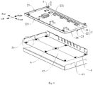
- a switching device 100 for a multi-split air conditioner will be described with reference to Figs. 1-9 .
- the switching device 100 is suitable for an air conditioner, such as a multi-split air conditioner or the like.
- the switching device 100 for the multi-split air conditioner includes a base 1, a drain tank 2, a plurality of damping pads 3, and a plurality of fixing members 4.
- the base 1 may be a bottom support of the switching device 100.
- the base 1 includes a bottom wall and a side wall, and the side wall of the base 1 surrounds the bottom wall of the base 1 and extends upwards from an edge of the bottom wall.
- the bottom wall of the base 1 may be formed in a substantially rectangular shape, but is not limited thereto.
- the bottom wall of the base 1 may be formed in a circular shape, a triangular shape, or an irregular shape.
- the specific shape thereof may be adjusted and designed according to the specification of the air conditioner, and the present disclosure does not particularly limit this.
- the side wall of the base 1 may surround the bottom wall of the base 1 and extend vertically upwards from the bottom wall of the base 1.
- the structure is simple, the processing is convenient, and it is easy for the base assembly 100 to be assembled with parts, such as a housing, of the air conditioner.
- the drain tank 2 is disposed in the base 1, and a bottom surface of the drain tank 2 is spaced apart from the bottom wall of the base 1 in an up and down direction.
- the drain tank 2 includes a drain-tank bottom wall 21 and a drain-tank side wall 22.
- the drain-tank side wall 22 surrounds the drain-tank bottom wall 21 and extends upwards from an edge of the drain-tank bottom wall 21 to define a water collecting sump between the drain-tank bottom wall 21 and the drain-tank side wall 22. Thereby, it is convenient for the drain tank 2 to collect condensed water or the like generated by heat exchange parts of the air conditioner.
- the lower surface of the drain-tank bottom wall 21 is spaced apart from the bottom wall of the base 1 in an up and down direction. That is, the lower surface of the drain-tank bottom wall 21 is not in direct contact with the bottom wall of the base 1. Thereby, it is possible to effectively prevent the noise generated when the refrigerant flows through the heat exchange system from being propagated through the drain tank 2 to the base 1, thereby greatly reducing the noise of the air conditioner using the base assembly 100.
- the drain-tank side wall 22 is provided with a drain pipe 23 disposed adjacent to the drain-tank bottom wall 21 of the drain tank.
- the side wall of the base 1 is provided with a mounting portion 11, and the drain pipe 23 passes through the mounting portion 11 to facilitate the discharge of water in the water collecting sump.
- the mounting portion 11 may be formed as a U-shaped groove (as shown in Fig. 1 ) penetrating a top of the side wall of the base 1, but is not limited thereto.
- the mounting portion 11 may also be formed as a through hole (not shown) penetrating the direction of the side wall of the base 1 in a thickness direction of the side wall of the base 1.
- the plurality of damping pads 3 are disposed on the drain tank 2 and arranged at intervals in a circumferential direction of the drain tank 2.
- the drain-tank side wall 22 may be provided with a flange 221 extending horizontally towards a center of the drain tank 2, and the damping pad 3 may be disposed on the flange 221.
- the left side wall and the right side wall of the drain tank 2 each are provided with the flange 221, and four damping pads 3 are provided.
- the flange 221 of the left side wall of the drain tank 2 is provided with two damping pads 3, and the right side wall of the drain tank 2 is provided with other two damping pads 3.
- the damping pad 3 may be connected to the drain tank 2 by a threaded fastener 5.
- the threaded fastener 5 may be a screw, a bolt or the like.
- the damping pad 3 may be provided with a screw hole through which the threaded fastener 5 may be connected to the drain tank 2. The structure is simple and the assembling is convenient.
- the plurality of fixing members 4 are correspondingly disposed to the plurality of damping pads 3 and further connected to the side wall of the base 1, and all the plurality of fixing members 4 are spaced apart from the drain tank 2. Specifically, referring to Fig. 2 and combining with Fig. 3 , the fixing member 4 may be firstly fitted with the damping pad 3 and then connected to the side wall of the base 1, and the drain tank 2 is spaced apart from the fixing member 4 by the damping pad 3.
- the fixing member 4 may be connected to the side wall of the base 1 by a screw or the like (not shown).
- the fixing member 4 may be first fitted with the damping pad 3, and then the fixing member 4 is connected to the side wall of the base 1 by the screw.
- the drain tank 2 can be firmly fixed to the base 1, and the fixing member 4 can be effectively prevented from being in direct contact with the drain tank 2. Therefore, it is possible to effectively prevent the noise generated when the refrigerant flows through the heat exchange system from being propagated through the drain tank 2 to the side wall of the base 1, thereby further reducing the noise of the air conditioner using the switching device 100, expanding the application occasion and installation position of the air conditioner, and improving the comfort of the air conditioner.
- the vibration of the switching device 100 can be effectively reduced, and the stability of the switching device 100 can be improved.
- the drain tank 2 is spaced apart from the fixing member 4.
- each damping pad 3 has a clamping slot 31 in a middle portion thereof.
- the above “middle portion” refers to a middle portion in a broad sense, and specifically, a portion between a upper surface and a lower surface of the damping pad 3 can be understood as "the middle portion of the damping pad 3".
- the damping pad 3 may be formed in a substantially cylindrical shape, and the clamping slot 31 may be formed as an annular slot extending along a circumferential direction of the damping pad 3, but is not limited thereto.
- Each fixing member 4 includes an engaging part 41 and a connecting part 42.
- the engaging part 41 has a groove 411 recessed from a side (for example, a front side in Fig. 3 ) of the engaging part 41 to a center of the engaging part 41, and the portion of the damping pad 3 where the clamping slot 31 is formed goes into the groove 41 through an opening of the groove 411 and is fitted with a bottom of the groove 411.
- the connecting part 42 is connected to a side (for example, a left side in Fig. 3 ) of the engaging part 41 adjacent to the side wall of the base 1 and is connected to the side wall of the base 1.
- the groove 411 may be generally formed in a U shape, and the bottom of the groove 411 may be understood as a closed end of the U shape.
- the bottom of the groove 411 may be first caught at the clamping slot 31, and then the connecting part 42 is fixed to the side wall of the base 1 by the screw.
- the structure is simple and the assembling is convenient.
- the fixing member 4 may be a sheet metal part, but is not limited thereto.
- the drain tank 2 can be fixed to the side wall of the base 1 firmly, so as to improve the reliability of the base assembly 100.
- each damping pad 3 may be a rubber member, but is not limited thereto.
- the damping pad 3 may also be a plastic member or the like.
- the bottom wall of the base 1 is provided with at least one support damping pad 6, and the support damping pad 6 is located between the bottom surface of the drain tank 2 and the bottom wall of the base 1.
- one or more support damping pads 6 may be provided.
- a plurality of support damping pads 6 are provided, and specifically nine support damping pads 6 are provided.
- the drain tank 2 can be supported by the support damping pad 6, such that the position of the drain tank 2 is stabilized, thereby improving the performance of the drain tank 2, and the propagation of the noise generated by the refrigerant to the base 1 can be reduced by the support damping pad 6.
- the vibration of the switching device 100 can be effectively reduced, and the stability of the switching device 100 can be improved.
- the support damping pad 6 may be a rubber member, but is not limited thereto.
- the support damping pad 6 may also be a plastic member or the like.
- an upper surface of the support damping pad 6 is formed with a blind hole 61 recessed downwards, and the support damping pad 6 may be formed substantially in the shape of a cylinder.
- a cross section of the blind hole 61 may have a circular shape, and a central axis of the blind hole 61 may coincide with a central axis of the support damping pad 6. Therefore, the material of the support damping pad 6 can be effectively reduced, thereby effectively reducing the material cost of the support damping pad 6.
- the weight of the support damping pad 6 is effectively reduced, and the contact area of the support damping pad 6 and the drain tank 2 is increased, thereby further improving the stability of the drain tank 2.
- an outer peripheral wall of the support damping pad 6 is provided with at least one weight-reducing groove 62.
- One or more weight-reducing grooves 62 may be provided.
- the weight-reducing groove 62 may be formed by recessing the outer peripheral wall of the support damping pad 6 towards a center of the support damping pad 6.
- the weight-reducing groove 62 may extend along a circumferential direction of the support damping pad 6 or may extend along an axial direction of the support damping pad 6, which is not specifically limited in the present disclosure.
- one weight-reducing groove 62 is provided, and extends along the circumferential direction of the support damping pad 6, such that the structure is simple and the processing is easy.
- the switching device 100 also includes a positioning screw 7.
- the positioning screw 7 penetrates through the bottom wall of the base 1 and a bottom wall of the blind hole 61 of the support damping pad 6 from the bottom up, so as to connect the support damping pad 6 to the base 1. Therefore, the support damping pad 6 can be firmly connected to the bottom wall of the base 1, such that the position of the support damping pad 6 is stabilized, thereby improving the performance of supporting, noise reduction and vibration damping of the support damping pad 6.
- the support damping pad 6 may be provided with a positioning hole configured to be fitted with the positioning screw 7, and an inner diameter of the positioning hole may be slightly smaller than an outer diameter of the positioning screw 7, such that the fit between the positioning hole and the positioning screw 7 can be closer and firmer.
- the positioning screw 7 sequentially passes through the bottom wall of the base 1 and the positioning hole from the bottom up to fix the support damping pad 6 to the base 1. Thereby, the assembling difficulty of the support damping pad 6 is reduced, and the firmness of the support damping pad 6 is improved.
- the positioning hole may be located below the blind hole 61 and penetrate the bottom wall of the blind hole 61. That is, the positioning hole may be formed as a through hole. Thereby, the firmness of the support damping pad 6 is further improved, the structure is simple, the processing is convenient, and the processing cost is reduced.
- a sponge body 24 may be disposed to the bottom surface of the drain tank 2. Thereby, condensation on the bottom surface of the drain tank 2 can be effectively reduced, and the noise can be further prevented from being propagated downwards through the bottom of the drain tank 2. In addition, the vibration of the base assembly 100 can be further reduced.
- the sponge body 24 may be adhered to the bottom surface of the drain tank 2.
- the area of the sponge body 24 may be substantially the same with that of the bottom surface of the drain tank 2, and one or more sponge bodies 24 may be provided.
- the sponge body 24 is provided with a first relief portion configured to avoid the support damping pad 6, such that the support damping pad 6 can be in direct contact with the bottom surface of the drain tank 2, thereby ensuring the stability of the drain tank 2.
- an anti-vibration gum 12 is disposed on the bottom wall of the base 1. Specifically, the anti-vibration gum 12 may be adhered to an inner wall of the base 1 and located below the drain tank 2. Specifically, the anti-vibration gum 12 may be located below the sponge body 24. Thereby, the propagation of the noise and the vibration of the base assembly 100 can be further reduced, thus further improving the effect of vibration reduction and noise reduction.
- a plurality of pieces of anti-vibration gum 12 may be provided, and the plurality of pieces of anti-vibration gum 12 are spliced together on the inner wall of the base 1.
- the plurality of pieces of anti-vibration gum 12 are spliced together on the inner wall of the base 1.
- four pieces of anti-vibration gum 12 are provided.
- the anti-vibration gum 12 may be formed in a substantially rectangular shape, but is not limited thereto.
- the anti-vibration gum 12 may be provided with a second relief portion 121 in a portion thereof adjacent to the support damping pad 6, so as to facilitate the assembling of the support damping pad 6.
- the multi-split air conditioner includes an outdoor unit and a plurality of indoor units having a plurality of first ports and a plurality of second ports.
- the outdoor unit is connected to the plurality of indoor units through the switching device 100, and the plurality of indoor units may be respectively disposed in a plurality of rooms, such that separate cooling or heating in different rooms can be realized by the switching device 100.
- "a plurality" means two or more, unless specified otherwise.
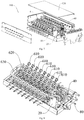
- the switching device 100 includes a housing 10, a gas-liquid separator 20, a plurality of first indoor-unit connection tubes 30, at least one heat exchange part 40, and a plurality of second indoor-unit connection tubes 50.
- first and second are used herein for purposes of description and are not intended to indicate or imply relative importance or significance or to imply the number of indicated technical features.
- the feature defined with “first” and “second” may include one or more this feature.
- the bottom of the housing 10 is open and the housing is arranged above the base 1.
- the housing 10 functions to close and protect the various parts disposed therein.
- the gas-liquid separator 20 is disposed in the housing 10, and the gas-liquid separator 20 may be used for a gas-liquid separation of a gas-liquid two-phase refrigerant entering from the outdoor unit, so as to improve the heating and cooling effects.
- the gas-liquid separator 20 has an inlet 210, a first outlet 220 and a second outlet 230.
- the inlet 210 is configured to be connected to the outdoor unit, such that the refrigerant entering through the inlet 210 is discharged out of the first outlet 220 and the second outlet 230 respectively after being subjected to the gas-liquid separation in the gas-liquid separator 20.
- the gas-liquid separator 20 can separate the gas-liquid two-phase refrigerant, such that the gaseous refrigerant flows out of the gas output pipe, and the liquid refrigerant flows out of the liquid output pipe.
- the gaseous refrigerant can flow from the gas side to the indoor units for heating, and on the contrary, the liquid refrigerant flows from the liquid side to the indoor units for cooling, in which the control of the different indoor units is realized separately by the reverse control of the corresponding solenoid valve.
- the first outlet 220 is preferably disposed to the top of the gas-liquid separator 20
- the second outlet 230 is preferably disposed to a lower portion of the gas-liquid separator 20.
- the inlet 210 may be in the form of a section of inlet pipe, and an end of the inlet pipe preferably extends into the gas-liquid separator 20, so as to provide a better gas-liquid separation effect.
- An end of the heat exchange part 40 is connected to the second outlet 231 of the gas-liquid separator 21. Therefore, by arranging the heat exchange part 40 downstream of the liquid refrigerant outlet of the gas-liquid separator 20, the separated liquid refrigerant enters the heat exchange part 40, and is subjected to the heat exchange and supercooling of the heat exchange part 40, such that it is possible to effectively ensure that the refrigerant flowing through the heat exchange part 40 is completely liquid.
- the plurality of first indoor-unit connection tubes 30 are spaced apart from one another in a first direction (e.g. a length direction in Fig. 6 ), and the first outlet 220 is connected to the plurality of first ports respectively via the plurality of first indoor-unit connection tubes 30.
- the plurality of second indoor-unit connection tubes 50 are spaced apart from one another in the first direction, and another end of the heat exchange part 40 is connected to the plurality of second ports respectively via the plurality of second indoor-unit connection tubes 50.
- the circulation flow of the refrigerant among the indoor unit, the first indoor-unit connection tube 30 and the second indoor-unit connection tube 50 can be realized after the indoor unit is assembled in place with the first indoor-unit connection tube 30 and the second indoor-unit connection tube 50 of the switching device 100 through the first port and the second port, and the connection between the switching device 100 and the indoor unit is facilitated.
- the plurality of first indoor-unit connection tubes 30 and the plurality of second indoor-unit connection tubes 50 are preferably arranged at even intervals in the first direction.
- the plurality of second indoor-unit connection tubes 50 are spaced apart from the plurality of first indoor-unit connection tubes 30 in a second direction perpendicular to the first direction.
- the first indoor-unit connection tube 30 and the corresponding second indoor-unit connection tube 50 i.e., the second indoor-unit connection tube 50 connected to the same indoor unit to which the first indoor unit 30 is connected
- have a one-to-one correspondence in the second direction e.g., the first indoor-unit connection tube 30 and the second indoor-unit connection tube 50 are aligned in an up and down direction, in the example of Fig. 6 ).
- the first indoor-unit connection tube 30 and the second indoor-unit connection tube 50 connected to the indoor unit are arranged in two layers, which relatively reduces a size of the switching device 100 in the first direction.
- Part of the plurality of first indoor-unit connection tubes 30 and the plurality of second indoor-unit connection tubes 50 are spaced apart from the rest of the first indoor-unit connection tubes and the second indoor-unit connection tubes in the second direction.
- the first indoor-unit connection tubes 30 and the second indoor-unit connection tubes 50 connected to the indoor units are respectively arranged in plurality of layers, which can further reduce the size of the switching device 100 in the first direction, thereby making the structure of entire switching device 100 simple and compact, and thus expanding the installation position and application occasion of the switching device 100.
- the indoor unit may have one first port and one second port respectively, the plurality of first indoor-unit connection tubes 30 are in one-to-one correspondence to the plurality of first ports, and the plurality of second indoor-unit connection tubes 50 are in one-to-one correspondence to the plurality of second ports.
- the first indoor-unit connection tube 30 and the second indoor-unit connection tube 50 both extend out of the side wall of the housing 10, such that the "first direction" may be the length direction of the housing 1 shown in Fig. 6 and the "second direction” may be a height direction of the housing 10 shown in Fig. 6 .
- the switching device 100 according to the present disclosure can be connected to more than six indoor units (e.g., the switching device 100 can be connected to sixteen indoor units in the example of Fig. 6 ), thereby implementing the control of the plurality of rooms.
- first direction may also be the length direction of the housing 10 shown in Fig. 6
- second direction is a width direction of the housing 10 shown in Fig. 6
- both the first indoor-unit connection tube 30 and the second indoor-unit connection tube 50 extend out of a top wall of the housing 1.
- first direction may be inclined with respect to the length direction of the housing 10 shown in Fig 6 .
- specific orientations of the "first direction” and the “second direction” may be specifically configured according to the actual assembling requirements of the first indoor-unit connection tube 30 and the second indoor-unit connection tube 50, so as to better meet the requirements of practical application occasions and installation positions.
- the switching device 100 for the multi-split air conditioner by arranging the first indoor-unit connection tubes 30 and the second indoor-unit connection tubes 50 configured to be connected with the indoor units into the plurality of layers, the length of the switching device 100 in the first direction can be relatively reduced, so as not to affect the application occasions and installation positions of the switching device 100. Further, by providing the gas-liquid separator 20 to perform the gas-liquid separation on the refrigerant, the state of the refrigerant can be improved and the noise of the multi-split air conditioner can be reduced, thereby further facilitating the heating or cooling of the multi-split air conditioner.
- the plurality of first indoor-unit connection tubes 30 are arranged in a plurality of layers spaced apart from one another in the second direction, and each layer of the first indoor-unit connection tubes 30 include at least one first indoor-unit connection tube 30; the plurality of second indoor-unit connection tubes 50 are arranged in a plurality of layers spaced apart from one another in the second direction, and each layer of the second indoor-unit connection tubes 50 include at least one second indoor-unit connection tube 50; and the plurality of layers of the first indoor-unit connection tubes 30 are spaced apart from the plurality of layers of the second indoor-unit connection tubes 50 in the second direction.
- the length of the switching device 100 in the first direction can be further reduced.
- first indoor-unit connection tubes 30 are staggered with one another in the first direction
- two adjacent layers of the second indoor-unit connection tube 50 are staggered with one another in the first direction.
- the first indoor-unit connection tubes 30 and the second indoor-unit connection tubes 50 can be arranged more compactly in the first direction, thus reducing the space occupied by the entire switching device 100, and further expanding the application occasions and installation positions of the switching device 100.
- sixteen first indoor-unit connection tubes 30 and sixteen second indoor-unit connection tubes 50 are respectively provided, and the first indoor-unit connection tubes 30 and the second indoor-unit connection tubes 50 are respectively arranged in two layers.
- Each layer includes eight first indoor-unit connection tubes 30 or eight second indoor-unit connection tubes 50 evenly spaced apart from one another in the length direction of the housing 10, and the four layers of the first indoor-unit connection tubes 30 and the second indoor-unit connection tubes 50 are evenly spaced from one another in the height direction of the housing 1.
- a group of the first indoor-unit connection tube 30 and the second indoor-unit connection tube 50 connected with the same indoor unit are aligned with each other in the up and down direction.
- the two layers of the first indoor-unit connection tubes 30 are staggered along the length direction of the housing 10, and the two layers of the second indoor-unit connection tubes 50 are staggered along the length direction of the housing 10, such that the first indoor-unit connection tubes 30 and the second indoor-unit connection tubes 50 can be arranged more compactly in the length direction of the housing 10, reducing the volume of the switching device 100, thereby reducing the space occupied by the switching device 100.
- the switching device 100 for the multi-split air conditioner further includes a solenoid valve assembly 60
- the solenoid valve assembly 60 includes a first U-shaped tube 620, a second U-shaped tube 630, and a plurality of solenoid valve units 610 arranged side by side. Therefore, by arranging the plurality of solenoid valve units 610 side by side, the entire solenoid valve assembly 60 has a modular design such that the entire structure of the solenoid valve assembly 60 is arranged in an orderly and compact manner.
- each solenoid valve unit 610 includes a first one-way solenoid valve 6110 and a second one-way solenoid valve 6120 for controlling different flow directions of heating and cooling of the multi-split air conditioner.
- the first U-shaped tube 620 is connected to the first outlet 220 and further connected to the plurality of first indoor-unit connection tubes 30 respectively via the plurality of first one-way solenoid valves 6110.
- the first one-way solenoid valve 6110 is configured to unidirectionally guide the refrigerant in the first U-shaped tube 620 into the corresponding first indoor-unit connection tube 30, while the refrigerant in the first indoor-unit connection tube 30 cannot enter the first U-shaped tube 620 through the first one-way solenoid valve 6110.
- the plurality of first indoor-unit connection tubes 30 are configured to be connected to the outdoor unit respectively via the plurality of second one-way solenoid valves 6120.
- the second one-way solenoid valve 6120 is configured to unidirectionally guide the refrigerant in the first indoor-unit connection tube 30 into the outdoor unit, while the refrigerant in the outdoor unit cannot enter the first indoor-unit connection tube 30 through the second one-way solenoid valves 6120.
- the gaseous refrigerant separated from the gas-liquid separator 20 enters the first one-way solenoid valve 6110 through the first U-shaped tube 620, and further enters the indoor unit through the first indoor-unit connection tube 30 to realize heating, and the refrigerant after heat exchange flows back to the outdoor unit through the second indoor-unit connection tube 50.
- the refrigerant flows through the second indoor-unit connection tube 50 to the indoor unit, then returns to the second U-shaped tube 630 through the second one-way solenoid valve 6120, and finally returns to the outdoor unit.
- the connection tubes i.e.
- the first indoor-unit connection tubes 30 and the second indoor-unit connection tubes 50) connecting the entire solenoid valve assembly 60 with the indoor units may be arranged in a single layer or a multi-layer array according to the actual size of the switching device 100, thereby balancing the dimensional control between the length and the height of the switching device 100.
- one of the first U-shaped tube 620 and the second U-shaped tube 630 is disposed at an inner side of the other one of the first U-shaped tube 620 and the second U-shaped tube 630. Therefore, by arranging the first U-shaped tube 620 and the second U-shaped tube 630 inside and outside, it is convenient for the first U-shaped tube 620 and the second U-shaped tube 630 to be connected with the plurality of solenoid valve units 610, and the structure of the entire solenoid valve assembly 60 is more compact.
- the plurality of solenoid valve units 610 may be located inside the first U-shaped tube 620 and the second U-shaped tube 630, and disposed adjacent to curved portions of the first U-shaped tube 620 and the second U-shaped tube 630.
- the first one-way solenoid valves 6110 and the second one-way solenoid valves 6120 of the plurality of solenoid valve units 610 are respectively connected to tube walls of the first U-shaped tube 620 and the second U-shaped tube 630 through pipes.
- the heat exchange part 40 is disposed inside the first U-shaped tube 620 and the second U-shaped tube 630. As shown in Figs. 6-8 , the heat exchange part 40 is located between ends of the first U-shaped tube 620 and also between ends of the second U-shaped tube 630, so as to more fully and reasonably utilize the internal space of the housing 10.
- One or more heat exchange parts 40 may be provided.
- two heat exchange parts 40 are sequentially disposed downstream of the gas-liquid separator 20, so as to achieve better heat exchange and supercooling.
- the heat exchange part 40 may be provided with a heat exchange portion on both sides thereof, and the refrigerant sequentially flows through the two heat exchange portions.
- the function of the heat exchange part 40 is substantially the same with that of the two heat exchange parts 40 shown in Fig 9 .
- a throttling device 90 is disposed between the two heat exchange parts 40, and the throttling device 90 may be a capillary tube or an electronic expansion valve, but is not limited thereto.
- the switching device 100 for the multi-split air conditioner further includes a check valve assembly 70.
- the check valve assembly 70 is disposed below the solenoid valve assembly 60, and the check valve assembly 70 may be disposed between the solenoid valve assembly 60 and the drain tank 2.
- the check valve assembly 70 includes a plurality of check valve units extending in a horizontal direction and arranged side by side. Thereby, the height of the switching device 100 in the up and down direction can be effectively reduced by flattening the check valve assembly 70.
- each of the check valve units includes a first check valve 710 and a second check valve 720 configured to be arranged in parallel between the heat exchange part 40 and the second indoor-unit connection tube 50 for controlling different flow directions of heating and cooling of the multi-split air conditioner.
- the first check valve 710 is configured to unidirectionally guide the refrigerant in the heat exchange part 40 to the indoor unit, while the refrigerant in the indoor unit cannot enter the heat exchange part 40 through the first check valve 710.
- the second check valve 720 is configured to unidirectionally guide the refrigerant in the indoor unit to the heat exchange part 40, while the refrigerant in the heat exchange part 40 cannot enter the indoor unit through the second check valve 720.
- the entire check valve assembly 70 can be connected during field installation.
- connection tubes i.e. the second indoor-unit connection tubes 50
- the connection tubes connecting the entire check valve assembly 70 to the indoor unit may be arranged in a single layer or a multi-layer array according to the actual size of the switching device 100, thereby balancing the dimensional control between the length and height of the switching device 100.
- the first check valve 710 and the second check valve 720 are arranged in the up and down direction as shown in Fig 6 .
- the size of the entire check valve assembly 70 in the length direction of the housing 10 can be reduced, thus making the entire structure of the switching device 100 more compact.
- the pipe connected between the second check valve 720 and the heat exchange part 40 has an extension section 80 that extends out of the housing 10.
- An end of the first U-shaped tube 620 and an end of the second U-shaped tube 630 may respectively extend out of the housing 10.
- the above ends of the first U-shaped tubes 620, the above ends of the second U-shaped tubes 630, and the extension sections 80 of multiple switching devices 100 may be respectively connected together in one to one correspondence, thereby realizing the series connection of the multiple switching devices 100 and facilitating the expansion of the number of ports of the indoor units.
- the gas-liquid separator 20 is configured to be disposed adjacent to the outdoor unit.
- the gas-liquid separator 20 is located in the housing 1 and at a side close to the outdoor unit, and the main function of the gas-liquid separator 20 is to separate the gas-liquid two-phase refrigerant entering from the outdoor unit, such that the gaseous refrigerant is discharged from the heating side, and the liquid refrigerant is discharged from the cooling side, thereby achieving better cooling and heating effects.
- the placement manner of the gas-liquid separator 20 is not limited to a vertical or horizontal type, as long as the gas-liquid separation function can be realized.
- the housing 10 has a substantially cuboid shape, and the first direction is the length direction of the housing 10 shown in Fig. 6 .
- the gas-liquid separator 20, the heat exchange part 40, the solenoid valve assembly 60 and the check valve assembly 70 are all disposed in the housing 10, and the solenoid valve assembly 60 is arranged above the check valve assembly 70.
- the solenoid valve assembly 60 is preferably arranged direct above the check valve assembly 70 so as to further improve the compactness of the entire switching device 100.
- the solenoid valve assembly 60 and the check valve assembly 70 are disposed at one side (e.g. a left side in Fig. 6 ) in the length direction of the housing 10.
- the solenoid valve assembly 60 and the check valve assembly 70 may be adjacent to a left side wall of the housing 10, while the gas-liquid separator 20 and the heat exchange part 40 are disposed at the other side (e.g. a right side in Fig. 6 ) in the length direction of the housing 10, and the gas-liquid separator 20 and the heat exchange part 40 are arranged sequentially in the width direction of the housing 10.
- the gas-liquid separator 20 and the heat exchange part 40 may be adjacent to a right side wall of the housing 10. Therefore, by adopting the above arrangement, the structure of the entire switching device 100 is more compact and the space occupied by the switching device 100 is reduced, such that the application occasion and the installation position of the switching device 100 will not be affected.
- the housing 10 includes a top cover 120 removably disposed on the top of the housing 10 for ease of maintenance or the like.
- the housing 1 is a sheet metal member, but is not limited thereto.
- an electric control box assembly 910 is disposed outside the housing 10.
- the electric control box assembly 910 is arranged vertically and disposed to a side surface of the housing 10.
- the electric control box assembly 910 may be hung on the side surface of the housing 10, but is not limited to being fixed to any one side surface, as long as the entire electric control box assembly 910 can be fixed, such that the electric control box assembly 910 can implement the control function.
- the electric control box assembly 910 may be connected to an electric control component such as a solenoid valve or the like in the housing 10.
- the switching device 100 for the multi-split air conditioner can realize separate control of cooling and heating of different indoor units.
- the main principle and realization method thereof are that the gas-liquid separator 20 separates the gas-liquid two-phase refrigerant such that the gaseous refrigerant flows out of the first outlet 220 and flows from the gas side to the corresponding indoor unit for heating, while the liquid refrigerant flows out of the second outlet 230 and flows from the liquid side to the corresponding indoor unit for cooling.
- the separate control of different indoor units is realized by the reverse control of the corresponding solenoid valve assembly 60.
- the first one-way solenoid valve 6110 corresponding to the indoor unit for heating is opened (in this case, the second one-way solenoid valve 6120 corresponding to the indoor unit for heating is closed) and the second one-way solenoid valve 6120 corresponding to the indoor unit for cooling is opened (in this case, the first one-way solenoid valve 6110 corresponding to the indoor unit for cooling is closed).
- the refrigerant in the outdoor unit first enters the gas-liquid separator 20 of the switching device 100 for gas-liquid separation, the separated gaseous refrigerant is discharged out of the first outlet 220, sequentially flows through the first U-shaped tube 620, the corresponding first one-way solenoid valve 6110 and the first indoor-unit connection tube 30, then enters the indoor unit for heating, and the refrigerant after heat exchange returns to the outdoor unit through the second indoor-unit connection tube 50, the second check valve 720 and the second U-shaped tube 630.
- the separated liquid refrigerant is discharged out of the second outlet 230, sequentially flows through the heat exchange part 40, the throttling device 90, the heat exchange part 40, the first check valve 710 and the second indoor-unit connection tube 50, then enters the indoor unit for cooling, and the refrigerant after heat exchange returns to the outdoor unit through the first indoor-unit connection tube 30, the second one-way solenoid valve 6120 and the second U-shaped tube 630.
- the switching device 100 for the multi-split air conditioner can effectively prevent the noise generated when the refrigerant flows through the heat exchange system from being propagated through the drain tank 2 to the base 1, thereby greatly reducing the noise of using the air conditioner, expanding the application occasions and installation positions of the air conditioner, improving the comfort of the air conditioner, and providing a simple structure, convenient assembling and a low processing cost.
- the entire switching device 100 is hierarchical and modular, thus providing great convenience for on-site maintenance.
- the switching device 100 may be disposed outside the outdoor unit, thereby facilitating maintenance of the switching device 100 and various components in the outdoor unit.
- a multi-split air conditioner according to a second aspect of embodiments of the present disclosure includes the switching device 100 for the multi-split air conditioner according to the above first aspect of embodiments of the present disclosure.
Landscapes
- Engineering & Computer Science (AREA)
- Mechanical Engineering (AREA)
- General Engineering & Computer Science (AREA)
- Chemical & Material Sciences (AREA)
- Combustion & Propulsion (AREA)
- Physics & Mathematics (AREA)
- Thermal Sciences (AREA)
- Other Air-Conditioning Systems (AREA)
- Air Conditioning Control Device (AREA)
Abstract
Description
- The present disclosure relates to a technical field of air conditioners, more particularly to a switching device for a multi-split air conditioner and a multi-split air conditioner having the same.
- In the related art, in the switching device of the air conditioner, the drain tank is usually disposed inside the base, and the heat exchange part or the like is arranged above the drain tank, such that the drain tank can collect the condensed water generated by the heat exchange part. However, the noise generated when the refrigerant flows through the heat exchange system will be propagated to the base through the drain tank, which enlarges the noise of the air conditioner, thereby greatly limiting the application occasions and installation positions of the air conditioner.
- In addition, although the switching device of the air conditioner can realize the separate cooling and heating of different indoor units through the valve body and the related control, due to the limitation of system setting and structural space, the number of indoor units that can be connected is relatively limited, generally less than six ports, i.e., the capacity is not large enough. If the size of the cabinet of the switching device is increased proportionally on the existing basis, the entire device will be too large, thus affecting the application occasion and the installation position. In addition, many of the existing small-sized switching devices are foamed inside the cabinet, thus making the entire refrigeration part unable to be repaired.
- The present disclosure aims to solve at least one of the technical problems existing in the related art. To this end, an objective of the present disclosure is to provide a switching device for a multi-split air conditioner, which can effectively reduce the noise of the air conditioner and tends not to affect the application occasion and the installation position thereof.
- Another objective of the present disclosure is to provide a multi-split air conditioner having the above switching device.
- The switching device for the multi-split air conditioner according to a first aspect of the present disclosure includes: a base including a bottom wall and a side wall surrounding the bottom wall and extending upwards from an edge of the bottom wall; a drain tank disposed in the base and having a bottom surface spaced apart from the bottom wall of the base in an up and down direction; a plurality of damping pads disposed to the drain tank and arranged at intervals in a circumferential direction of the drain tank; a plurality of fixing members respectively disposed to the plurality of damping pads, and connected to the side wall of the base, all the plurality of fixing members being spaced apart from the drain tank.
- In the switching device for the multi-split air conditioner according to the present disclosure, by spacing the bottom surface of the drain tank apart from the inner wall of the base and by disposing the damping pad to the drain tank, the drain tank is spaced apart from the fixing member. Thereby, the noise generated when the refrigerant flows through the heat exchange system is effectively prevented from being propagated through the drain tank to the base, thus greatly reducing the noise of the air conditioner using the base assembly, expanding the application occasion and the installation position of the air conditioner, and improving the comfort of the air conditioner, without affecting the application occasion and the installation position of the switching device.
- In addition, the switching device for the multi-split air conditioner according to the present disclosure may further include following additional technical features.
- According to some embodiments of the present disclosure, each damping pad has a clamping slot in a middle portion thereof, and the clamping slot is configured as an annular slot extending along a circumferential direction of the damping pad. Each fixing member includes: an engaging part having a groove recessed from a side of the engaging part to a center of the engaging part, the middle portion where the clamping slot is formed going into the groove through an opening of the groove and being fitted with a bottom of the groove; a connecting part connected to a side of the engaging part adjacent to the side wall of the base and further connected to the side wall of the base.
- Further, the bottom wall of the base is provided with at least one support damping pad thereon, and the support damping pad is arranged between the bottom surface of the drain tank and the bottom wall of the base.
- According to some embodiments of the present disclosure, the upper surface of the support damping pad is provided with a blind hole recessed downwards, and the switching device further includes: a positioning screw penetrating through the bottom wall of the base and the bottom wall of the blind hole from the bottom up, so as to connect the support damping pad to the base.
- Optionally, a sponge body is disposed to the bottom surface of the drain tank.
- Specifically, an anti-vibration gum is disposed on the bottom wall of the base.
- According to some embodiments of the present disclosure, the multi-split air conditioner includes an outdoor unit and a plurality of indoor units having a plurality of first ports and a plurality of second ports. The switching device further includes: a housing having an open bottom and arranged above the base; a gas-liquid separator disposed in the housing, the gas-liquid separator has an inlet, a first outlet and a second outlet, the inlet being configured to be connected to the outdoor unit; a plurality of first indoor-unit connection tubes spaced apart from one another in a first direction, the first outlet being connected to the plurality of first ports respectively via the plurality of first indoor-unit connection tubes; at least one heat exchange part having an end connected to the second outlet; and a plurality of second indoor-unit connection tubes spaced apart from the plurality of first indoor-unit connection tubes in a second direction perpendicular to the first direction, and the plurality of second indoor-unit connection tubes being spaced apart from one another in the first direction, the heat exchange part having another end connected to the plurality of second ports respectively via the plurality of second indoor-unit connection tubes, and part of the plurality of first indoor-unit connection tubes and the plurality of second indoor-unit connection tubes are spaced apart from the rest of the first indoor-unit connection tubes and the second indoor-unit connection tubes in the second direction.
- Further, the switching device further includes: a solenoid valve assembly including a plurality of solenoid valve units arranged side by side, a first U-shaped tube and a second U-shaped tube, each solenoid valve unit including a first one-way solenoid valve and a second one-way solenoid valve, the first U-shaped tube being connected to the first outlet and further connected to the plurality of first indoor-unit connection tubes respectively via the plurality of first one-way solenoid valves, the plurality of first indoor-unit connection tubes being configured to be connected to the outdoor unit respectively via the plurality of second one-way solenoid valves, the first one-way solenoid valve being configured to unidirectionally guide a refrigerant in the first U-shaped tube to the corresponding first indoor-unit connection tube, the second one-way solenoid valve being configured to unidirectionally guide the refrigerant in the first indoor-unit connection tube to the outdoor unit, and one of the first U-shaped tube and the second U-shaped tube being disposed at an inner side of the other one of the first U-shaped tube and the second U-shaped tube; and a check valve assembly disposed below the solenoid valve assembly, the check valve assembly including a plurality of check valve units arranged side by side and extending in a horizontal direction, each check valve unit including a first check valve and a second check valve configured to be arranged in parallel between the heat exchange part and the second indoor-unit connection tube, the first check valve being configured to unidirectionally guide the refrigerant in the heat exchange part to the indoor unit, and the second check valve being configured to unidirectionally guide the refrigerant in the indoor unit to the heat exchange part.
- According to some embodiments of the present disclosure, the housing has a substantially cuboid shape, and the first direction is a length direction of the housing, the heat exchange part. The solenoid valve assembly and the check valve assembly are all disposed in the housing, and the solenoid valve assembly is arranged above the check valve assembly. The solenoid valve assembly and the check valve assembly are disposed at one side in the length direction of the housing, while the gas-liquid separator and the heat exchange part are disposed at the other side in the length direction of the housing. The gas-liquid separator and the heat exchange part are arranged sequentially in a width direction of the housing. An electric control box assembly is disposed outside the housing. The electric control box assembly is arranged vertically and disposed to a side surface of the housing.
- A multi-split air conditioner according to a second aspect of the present disclosure includes the switching device for the multi-split air conditioner according to the above first aspect of the present disclosure.
- Additional aspects and advantages of embodiments of present disclosure will be given in part in the following descriptions, become apparent in part from the following descriptions, or be learned from the practice of the embodiments of the present disclosure.
- The above and/or additional aspects and advantages of the present disclosure will become apparent and more readily appreciated from descriptions of embodiments made with reference to the following drawings, in which:
-
Fig. 1 is a perspective view of a base according to an embodiment of the present disclosure; -
Fig. 2 is an exploded view of the base shown inFig. 1 ; -
Fig. 3 is an enlarged view of portion A circled inFig. 2 ; -
Fig. 4 is another exploded view of the base shown inFig. 1 ; -
Fig. 5 is an enlarged view of portion B circled inFig. 4 ; -
Fig. 6 is an exploded view of a switching device according to an embodiment of the present disclosure; -
Fig. 7 is another exploded view of the switching device shown inFig. 6 ; -
Fig. 8 is a schematic view showing the assembling of a base, a solenoid valve assembly, a check valve assembly, a gas-liquid separator and a heat exchange part shown inFig. 7 ; -
Fig. 9 is a schematic view of a switching device according to an embodiment of the present disclosure. -
- switching
device 100, -
base 1,mounting portion 11,anti-vibration gum 12,second relief portion 121, - drain
tank 2, drain-tank bottom wall 21, drain-tank side wall 22,flange 221,drain pipe 23,sponge body 24, -
damping pad 3,clamping slot 31, - fixing
member 4, engagingpart 41,groove 411, connectingpart 42, - threaded
fastener 5, supportdamping pad 6,blind hole 61, weight-reducinggroove 62,positioning screw 7, -
housing 10,top cover 120, - gas-
liquid separator 20,inlet 210,first outlet 220,second outlet 230, - first indoor-
unit connection tube 30,heat exchange part 40, second indoor-unit connection tube 50,solenoid valve assembly 60, -
solenoid valve unit 610, first one-way solenoid valve 6110, second one-way solenoid valve 6120, - first U-shaped
tube 620,second U-shaped tube 630, -
check valve assembly 70,first check valve 710,second check valve 720, -
extension section 80,throttling device 90, electriccontrol box assembly 910. - Embodiments of the present disclosure will be described in detail and examples of embodiments are illustrated in the drawings. The same or similar elements and the elements having the same or similar functions are denoted by like reference numerals throughout the descriptions. Embodiments described herein with reference to drawings are explanatory, serve to explain the present disclosure, and are not construed to limit embodiments of the present disclosure.
- In the description of the specification, it should be understood that the orientation or positional relationship indicated by the terms such as "central", "length", "width", "thickness", "upper", "lower", "front", "rear", "left", "right", "vertical", "horizontal", "top", "bottom", "inner", "outer", "axial" and "circumferential" and the like is based on the orientation or positional relationship shown in the drawings, only for convenience of description of the present disclosure and simplification, and is not intended to indicate or imply that the device or component referred to has a particular orientation, is constructed and operated in a particular orientation, and thus is not to be understood as limiting the present disclosure. In addition, terms such as "first" and "second" are used herein for purposes of description and are not intended to indicate or imply relative importance or significance or to imply the number of indicated technical features. Thus, the feature defined with "first" and "second" may comprise one or more of this features either explicitly or implicitly.
- In the description of the present disclosure, unless specified or limited otherwise, the terms "mounted", "connected", "coupled" and the like are used broadly, and may be, for example, fixed connections, detachable connections, or integral connections; may also be mechanical or electrical connections; may also be direct connections or indirect connections via intervening structures; may also be inner communications of two elements, which can be understood by those skilled in the art according to specific situations.
- A
switching device 100 for a multi-split air conditioner according to an embodiment of the present disclosure will be described with reference toFigs. 1-9 . Theswitching device 100 is suitable for an air conditioner, such as a multi-split air conditioner or the like. - As shown in
Fig. 1 , theswitching device 100 for the multi-split air conditioner according to a first aspect of embodiments of the present disclosure includes abase 1, adrain tank 2, a plurality of dampingpads 3, and a plurality of fixingmembers 4. Thebase 1 may be a bottom support of theswitching device 100. - Specifically, referring to
Figs. 1 and 2 , thebase 1 includes a bottom wall and a side wall, and the side wall of thebase 1 surrounds the bottom wall of thebase 1 and extends upwards from an edge of the bottom wall. The bottom wall of thebase 1 may be formed in a substantially rectangular shape, but is not limited thereto. For example, the bottom wall of thebase 1 may be formed in a circular shape, a triangular shape, or an irregular shape. The specific shape thereof may be adjusted and designed according to the specification of the air conditioner, and the present disclosure does not particularly limit this. The side wall of thebase 1 may surround the bottom wall of thebase 1 and extend vertically upwards from the bottom wall of thebase 1. The structure is simple, the processing is convenient, and it is easy for thebase assembly 100 to be assembled with parts, such as a housing, of the air conditioner. - The
drain tank 2 is disposed in thebase 1, and a bottom surface of thedrain tank 2 is spaced apart from the bottom wall of thebase 1 in an up and down direction. Specifically, referring toFig. 2 , thedrain tank 2 includes a drain-tank bottom wall 21 and a drain-tank side wall 22. The drain-tank side wall 22 surrounds the drain-tank bottom wall 21 and extends upwards from an edge of the drain-tank bottom wall 21 to define a water collecting sump between the drain-tank bottom wall 21 and the drain-tank side wall 22. Thereby, it is convenient for thedrain tank 2 to collect condensed water or the like generated by heat exchange parts of the air conditioner. - The lower surface of the drain-
tank bottom wall 21 is spaced apart from the bottom wall of thebase 1 in an up and down direction. That is, the lower surface of the drain-tank bottom wall 21 is not in direct contact with the bottom wall of thebase 1. Thereby, it is possible to effectively prevent the noise generated when the refrigerant flows through the heat exchange system from being propagated through thedrain tank 2 to thebase 1, thereby greatly reducing the noise of the air conditioner using thebase assembly 100. - Further, the drain-
tank side wall 22 is provided with adrain pipe 23 disposed adjacent to the drain-tank bottom wall 21 of the drain tank. The side wall of thebase 1 is provided with a mountingportion 11, and thedrain pipe 23 passes through the mountingportion 11 to facilitate the discharge of water in the water collecting sump. The mountingportion 11 may be formed as a U-shaped groove (as shown inFig. 1 ) penetrating a top of the side wall of thebase 1, but is not limited thereto. For example, the mountingportion 11 may also be formed as a through hole (not shown) penetrating the direction of the side wall of thebase 1 in a thickness direction of the side wall of thebase 1. - The plurality of damping
pads 3 are disposed on thedrain tank 2 and arranged at intervals in a circumferential direction of thedrain tank 2. Specifically, the drain-tank side wall 22 may be provided with aflange 221 extending horizontally towards a center of thedrain tank 2, and the dampingpad 3 may be disposed on theflange 221. For example, in the example ofFig. 2 , the left side wall and the right side wall of thedrain tank 2 each are provided with theflange 221, and four dampingpads 3 are provided. Theflange 221 of the left side wall of thedrain tank 2 is provided with two dampingpads 3, and the right side wall of thedrain tank 2 is provided with other two dampingpads 3. - It should be noted herein that, in the description of the present disclosure, "a plurality of' means two or more, for example, three or four, unless specified otherwise.
- Specifically, referring to
Fig. 2 and combining withFig. 3 , the dampingpad 3 may be connected to thedrain tank 2 by a threadedfastener 5. The threadedfastener 5 may be a screw, a bolt or the like. For example, the dampingpad 3 may be provided with a screw hole through which the threadedfastener 5 may be connected to thedrain tank 2. The structure is simple and the assembling is convenient. - The plurality of fixing
members 4 are correspondingly disposed to the plurality of dampingpads 3 and further connected to the side wall of thebase 1, and all the plurality of fixingmembers 4 are spaced apart from thedrain tank 2. Specifically, referring toFig. 2 and combining withFig. 3 , the fixingmember 4 may be firstly fitted with the dampingpad 3 and then connected to the side wall of thebase 1, and thedrain tank 2 is spaced apart from the fixingmember 4 by the dampingpad 3. The fixingmember 4 may be connected to the side wall of thebase 1 by a screw or the like (not shown). - For example, during assembling, the fixing
member 4 may be first fitted with the dampingpad 3, and then the fixingmember 4 is connected to the side wall of thebase 1 by the screw. Thereby, thedrain tank 2 can be firmly fixed to thebase 1, and the fixingmember 4 can be effectively prevented from being in direct contact with thedrain tank 2. Therefore, it is possible to effectively prevent the noise generated when the refrigerant flows through the heat exchange system from being propagated through thedrain tank 2 to the side wall of thebase 1, thereby further reducing the noise of the air conditioner using theswitching device 100, expanding the application occasion and installation position of the air conditioner, and improving the comfort of the air conditioner. In addition, the vibration of theswitching device 100 can be effectively reduced, and the stability of theswitching device 100 can be improved. - In the
switching device 100 for the multi-split air conditioner according to the embodiment of the present disclosure, since the bottom surface of thedrain tank 2 is spaced apart from the inner wall of thebase 1 and thedrain tank 2 is provided with the dampingpad 3, thedrain tank 2 is spaced apart from the fixingmember 4. Thereby, the noise generated when that the refrigerant flows through the heat exchange system is effectively prevented from being propagated through thedrain tank 2 to thebase 1, thus greatly reducing the noise and vibration of the air conditioner using theswitching device 100. Therefore, the application occasion and installation position of the switching device will not be affected, but will be expanded, and also, the comfort and stability of the air conditioner will be improved. - According to some embodiments of the present disclosure, referring to
Fig. 3 , each dampingpad 3 has a clampingslot 31 in a middle portion thereof. It can be understood that the above "middle portion" refers to a middle portion in a broad sense, and specifically, a portion between a upper surface and a lower surface of the dampingpad 3 can be understood as "the middle portion of the dampingpad 3". For example, in the example ofFig. 3 , the dampingpad 3 may be formed in a substantially cylindrical shape, and the clampingslot 31 may be formed as an annular slot extending along a circumferential direction of the dampingpad 3, but is not limited thereto. - Each fixing
member 4 includes anengaging part 41 and a connectingpart 42. The engagingpart 41 has agroove 411 recessed from a side (for example, a front side inFig. 3 ) of theengaging part 41 to a center of theengaging part 41, and the portion of the dampingpad 3 where the clampingslot 31 is formed goes into thegroove 41 through an opening of thegroove 411 and is fitted with a bottom of thegroove 411. The connectingpart 42 is connected to a side (for example, a left side inFig. 3 ) of theengaging part 41 adjacent to the side wall of thebase 1 and is connected to the side wall of thebase 1. For example, referring toFig. 3 , thegroove 411 may be generally formed in a U shape, and the bottom of thegroove 411 may be understood as a closed end of the U shape. During assembling, the bottom of thegroove 411 may be first caught at the clampingslot 31, and then the connectingpart 42 is fixed to the side wall of thebase 1 by the screw. The structure is simple and the assembling is convenient. - Alternatively, the fixing
member 4 may be a sheet metal part, but is not limited thereto. Thereby, thedrain tank 2 can be fixed to the side wall of thebase 1 firmly, so as to improve the reliability of thebase assembly 100. - According to some embodiments of the present disclosure, each damping
pad 3 may be a rubber member, but is not limited thereto. For example, the dampingpad 3 may also be a plastic member or the like. Thereby, the noise reduction effect can be effectively improved, the vibration of thebase assembly 100 can be reduced, the processing is convenient, and the material cost and the processing cost are low. - Further, the bottom wall of the
base 1 is provided with at least onesupport damping pad 6, and thesupport damping pad 6 is located between the bottom surface of thedrain tank 2 and the bottom wall of thebase 1. Specifically, one or moresupport damping pads 6 may be provided. For example, referring toFig. 4 , a plurality ofsupport damping pads 6 are provided, and specifically ninesupport damping pads 6 are provided. Thereby, thedrain tank 2 can be supported by thesupport damping pad 6, such that the position of thedrain tank 2 is stabilized, thereby improving the performance of thedrain tank 2, and the propagation of the noise generated by the refrigerant to thebase 1 can be reduced by thesupport damping pad 6. In addition, the vibration of theswitching device 100 can be effectively reduced, and the stability of theswitching device 100 can be improved. - Alternatively, the
support damping pad 6 may be a rubber member, but is not limited thereto. For example, thesupport damping pad 6 may also be a plastic member or the like. Thereby, the effects of noise reduction and vibration reduction can be effectively improved, the processing is convenient and the cost is low. - According to some embodiments of the present disclosure, referring to
Fig. 4 and combining withFig. 5 , an upper surface of thesupport damping pad 6 is formed with ablind hole 61 recessed downwards, and thesupport damping pad 6 may be formed substantially in the shape of a cylinder. A cross section of theblind hole 61 may have a circular shape, and a central axis of theblind hole 61 may coincide with a central axis of thesupport damping pad 6. Therefore, the material of thesupport damping pad 6 can be effectively reduced, thereby effectively reducing the material cost of thesupport damping pad 6. In addition, the weight of thesupport damping pad 6 is effectively reduced, and the contact area of thesupport damping pad 6 and thedrain tank 2 is increased, thereby further improving the stability of thedrain tank 2. - Optionally, an outer peripheral wall of the
support damping pad 6 is provided with at least one weight-reducinggroove 62. One or more weight-reducinggrooves 62 may be provided. The weight-reducinggroove 62 may be formed by recessing the outer peripheral wall of thesupport damping pad 6 towards a center of thesupport damping pad 6. The weight-reducinggroove 62 may extend along a circumferential direction of thesupport damping pad 6 or may extend along an axial direction of thesupport damping pad 6, which is not specifically limited in the present disclosure. For example, in the example ofFig. 5 , one weight-reducinggroove 62 is provided, and extends along the circumferential direction of thesupport damping pad 6, such that the structure is simple and the processing is easy. - Further, the
switching device 100 also includes apositioning screw 7. Referring toFig. 5 , thepositioning screw 7 penetrates through the bottom wall of thebase 1 and a bottom wall of theblind hole 61 of thesupport damping pad 6 from the bottom up, so as to connect thesupport damping pad 6 to thebase 1. Therefore, thesupport damping pad 6 can be firmly connected to the bottom wall of thebase 1, such that the position of thesupport damping pad 6 is stabilized, thereby improving the performance of supporting, noise reduction and vibration damping of thesupport damping pad 6. - According to some embodiments of the present disclosure, the
support damping pad 6 may be provided with a positioning hole configured to be fitted with thepositioning screw 7, and an inner diameter of the positioning hole may be slightly smaller than an outer diameter of thepositioning screw 7, such that the fit between the positioning hole and thepositioning screw 7 can be closer and firmer. - During assembling, the
positioning screw 7 sequentially passes through the bottom wall of thebase 1 and the positioning hole from the bottom up to fix thesupport damping pad 6 to thebase 1. Thereby, the assembling difficulty of thesupport damping pad 6 is reduced, and the firmness of thesupport damping pad 6 is improved. - Specifically, the positioning hole may be located below the
blind hole 61 and penetrate the bottom wall of theblind hole 61. That is, the positioning hole may be formed as a through hole. Thereby, the firmness of thesupport damping pad 6 is further improved, the structure is simple, the processing is convenient, and the processing cost is reduced. - According to some embodiments of the disclosure, a
sponge body 24 may be disposed to the bottom surface of thedrain tank 2. Thereby, condensation on the bottom surface of thedrain tank 2 can be effectively reduced, and the noise can be further prevented from being propagated downwards through the bottom of thedrain tank 2. In addition, the vibration of thebase assembly 100 can be further reduced. - The
sponge body 24 may be adhered to the bottom surface of thedrain tank 2. The area of thesponge body 24 may be substantially the same with that of the bottom surface of thedrain tank 2, and one ormore sponge bodies 24 may be provided. Further, thesponge body 24 is provided with a first relief portion configured to avoid thesupport damping pad 6, such that thesupport damping pad 6 can be in direct contact with the bottom surface of thedrain tank 2, thereby ensuring the stability of thedrain tank 2. - Further, an
anti-vibration gum 12 is disposed on the bottom wall of thebase 1. Specifically, theanti-vibration gum 12 may be adhered to an inner wall of thebase 1 and located below thedrain tank 2. Specifically, theanti-vibration gum 12 may be located below thesponge body 24. Thereby, the propagation of the noise and the vibration of thebase assembly 100 can be further reduced, thus further improving the effect of vibration reduction and noise reduction. - Alternatively, a plurality of pieces of
anti-vibration gum 12 may be provided, and the plurality of pieces ofanti-vibration gum 12 are spliced together on the inner wall of thebase 1. For example, in the example ofFig. 4 , four pieces ofanti-vibration gum 12 are provided. Thereby, the adhering difficulty of theanti-vibration gum 12 is effectively reduced, and the assembling efficiency is improved. - Specifically, the
anti-vibration gum 12 may be formed in a substantially rectangular shape, but is not limited thereto. Theanti-vibration gum 12 may be provided with asecond relief portion 121 in a portion thereof adjacent to thesupport damping pad 6, so as to facilitate the assembling of thesupport damping pad 6. - The multi-split air conditioner includes an outdoor unit and a plurality of indoor units having a plurality of first ports and a plurality of second ports. The outdoor unit is connected to the plurality of indoor units through the
switching device 100, and the plurality of indoor units may be respectively disposed in a plurality of rooms, such that separate cooling or heating in different rooms can be realized by theswitching device 100. In the description of the present disclosure, "a plurality" means two or more, unless specified otherwise. - As shown in
Fig. 6 andFig. 9 , theswitching device 100 includes ahousing 10, a gas-liquid separator 20, a plurality of first indoor-unit connection tubes 30, at least oneheat exchange part 40, and a plurality of second indoor-unit connection tubes 50. - It should be noted that, in descriptions of the present disclosure, terms such as "first" and "second" are used herein for purposes of description and are not intended to indicate or imply relative importance or significance or to imply the number of indicated technical features. Thus, the feature defined with "first" and "second" may include one or more this feature.
- The bottom of the
housing 10 is open and the housing is arranged above thebase 1. Thehousing 10 functions to close and protect the various parts disposed therein. The gas-liquid separator 20 is disposed in thehousing 10, and the gas-liquid separator 20 may be used for a gas-liquid separation of a gas-liquid two-phase refrigerant entering from the outdoor unit, so as to improve the heating and cooling effects. The gas-liquid separator 20 has aninlet 210, afirst outlet 220 and asecond outlet 230. Theinlet 210 is configured to be connected to the outdoor unit, such that the refrigerant entering through theinlet 210 is discharged out of thefirst outlet 220 and thesecond outlet 230 respectively after being subjected to the gas-liquid separation in the gas-liquid separator 20. - During the operation of the air conditioner, the gas-
liquid separator 20 can separate the gas-liquid two-phase refrigerant, such that the gaseous refrigerant flows out of the gas output pipe, and the liquid refrigerant flows out of the liquid output pipe. At the same time, the gaseous refrigerant can flow from the gas side to the indoor units for heating, and on the contrary, the liquid refrigerant flows from the liquid side to the indoor units for cooling, in which the control of the different indoor units is realized separately by the reverse control of the corresponding solenoid valve. In the following description of the present disclosure, an example, in which the separated gaseous refrigerant is discharged out of thefirst outlet 220 and the separated liquid refrigerant is discharged out of thesecond outlet 230, will be described for illustration. In this case, thefirst outlet 220 is preferably disposed to the top of the gas-liquid separator 20, and thesecond outlet 230 is preferably disposed to a lower portion of the gas-liquid separator 20. Theinlet 210 may be in the form of a section of inlet pipe, and an end of the inlet pipe preferably extends into the gas-liquid separator 20, so as to provide a better gas-liquid separation effect. - An end of the
heat exchange part 40 is connected to the second outlet 231 of the gas-liquid separator 21. Therefore, by arranging theheat exchange part 40 downstream of the liquid refrigerant outlet of the gas-liquid separator 20, the separated liquid refrigerant enters theheat exchange part 40, and is subjected to the heat exchange and supercooling of theheat exchange part 40, such that it is possible to effectively ensure that the refrigerant flowing through theheat exchange part 40 is completely liquid. - The plurality of first indoor-
unit connection tubes 30 are spaced apart from one another in a first direction (e.g. a length direction inFig. 6 ), and thefirst outlet 220 is connected to the plurality of first ports respectively via the plurality of first indoor-unit connection tubes 30. The plurality of second indoor-unit connection tubes 50 are spaced apart from one another in the first direction, and another end of theheat exchange part 40 is connected to the plurality of second ports respectively via the plurality of second indoor-unit connection tubes 50. Therefore, by providing the first indoor-unit connection tube 30 and the second indoor-unit connection tube 50, the circulation flow of the refrigerant among the indoor unit, the first indoor-unit connection tube 30 and the second indoor-unit connection tube 50 can be realized after the indoor unit is assembled in place with the first indoor-unit connection tube 30 and the second indoor-unit connection tube 50 of theswitching device 100 through the first port and the second port, and the connection between the switchingdevice 100 and the indoor unit is facilitated. The plurality of first indoor-unit connection tubes 30 and the plurality of second indoor-unit connection tubes 50 are preferably arranged at even intervals in the first direction. - The plurality of second indoor-
unit connection tubes 50 are spaced apart from the plurality of first indoor-unit connection tubes 30 in a second direction perpendicular to the first direction. Optionally, the first indoor-unit connection tube 30 and the corresponding second indoor-unit connection tube 50 (i.e., the second indoor-unit connection tube 50 connected to the same indoor unit to which the firstindoor unit 30 is connected) have a one-to-one correspondence in the second direction (e.g., the first indoor-unit connection tube 30 and the second indoor-unit connection tube 50 are aligned in an up and down direction, in the example ofFig. 6 ). Thereby, the first indoor-unit connection tube 30 and the second indoor-unit connection tube 50 connected to the indoor unit are arranged in two layers, which relatively reduces a size of theswitching device 100 in the first direction. - Part of the plurality of first indoor-
unit connection tubes 30 and the plurality of second indoor-unit connection tubes 50 (which may be one or more) are spaced apart from the rest of the first indoor-unit connection tubes and the second indoor-unit connection tubes in the second direction. Thereby, the first indoor-unit connection tubes 30 and the second indoor-unit connection tubes 50 connected to the indoor units are respectively arranged in plurality of layers, which can further reduce the size of theswitching device 100 in the first direction, thereby making the structure ofentire switching device 100 simple and compact, and thus expanding the installation position and application occasion of theswitching device 100. The indoor unit may have one first port and one second port respectively, the plurality of first indoor-unit connection tubes 30 are in one-to-one correspondence to the plurality of first ports, and the plurality of second indoor-unit connection tubes 50 are in one-to-one correspondence to the plurality of second ports. - For example, as shown in
Fig. 6 , the first indoor-unit connection tube 30 and the second indoor-unit connection tube 50 both extend out of the side wall of thehousing 10, such that the "first direction" may be the length direction of thehousing 1 shown inFig. 6 and the "second direction" may be a height direction of thehousing 10 shown inFig. 6 . Thereby, the length of theentire switching device 100 in the length direction is effectively saved, and the number of the indoor units to which theswitching device 100 can be connected is relatively expanded. For example, theswitching device 100 according to the present disclosure can be connected to more than six indoor units (e.g., theswitching device 100 can be connected to sixteen indoor units in the example ofFig. 6 ), thereby implementing the control of the plurality of rooms. Of course, the "first direction" may also be the length direction of thehousing 10 shown inFig. 6 , while the "second direction" is a width direction of thehousing 10 shown inFig. 6 . In this case, both the first indoor-unit connection tube 30 and the second indoor-unit connection tube 50 extend out of a top wall of thehousing 1. Alternatively, the "first direction" may be inclined with respect to the length direction of thehousing 10 shown inFig 6 . It can be understood that the specific orientations of the "first direction" and the "second direction" may be specifically configured according to the actual assembling requirements of the first indoor-unit connection tube 30 and the second indoor-unit connection tube 50, so as to better meet the requirements of practical application occasions and installation positions. - In the
switching device 100 for the multi-split air conditioner according to the embodiment of the present disclosure, by arranging the first indoor-unit connection tubes 30 and the second indoor-unit connection tubes 50 configured to be connected with the indoor units into the plurality of layers, the length of theswitching device 100 in the first direction can be relatively reduced, so as not to affect the application occasions and installation positions of theswitching device 100. Further, by providing the gas-liquid separator 20 to perform the gas-liquid separation on the refrigerant, the state of the refrigerant can be improved and the noise of the multi-split air conditioner can be reduced, thereby further facilitating the heating or cooling of the multi-split air conditioner. - According to some embodiments of the present disclosure, the plurality of first indoor-
unit connection tubes 30 are arranged in a plurality of layers spaced apart from one another in the second direction, and each layer of the first indoor-unit connection tubes 30 include at least one first indoor-unit connection tube 30; the plurality of second indoor-unit connection tubes 50 are arranged in a plurality of layers spaced apart from one another in the second direction, and each layer of the second indoor-unit connection tubes 50 include at least one second indoor-unit connection tube 50; and the plurality of layers of the first indoor-unit connection tubes 30 are spaced apart from the plurality of layers of the second indoor-unit connection tubes 50 in the second direction. Thereby, the length of theswitching device 100 in the first direction can be further reduced. Optionally, two adjacent layers of the first indoor-unit connection tubes 30 are staggered with one another in the first direction, and two adjacent layers of the second indoor-unit connection tube 50 are staggered with one another in the first direction. Thereby, the first indoor-unit connection tubes 30 and the second indoor-unit connection tubes 50 can be arranged more compactly in the first direction, thus reducing the space occupied by theentire switching device 100, and further expanding the application occasions and installation positions of theswitching device 100. - For example, in the example of
Fig. 6 , sixteen first indoor-unit connection tubes 30 and sixteen second indoor-unit connection tubes 50 are respectively provided, and the first indoor-unit connection tubes 30 and the second indoor-unit connection tubes 50 are respectively arranged in two layers. Each layer includes eight first indoor-unit connection tubes 30 or eight second indoor-unit connection tubes 50 evenly spaced apart from one another in the length direction of thehousing 10, and the four layers of the first indoor-unit connection tubes 30 and the second indoor-unit connection tubes 50 are evenly spaced from one another in the height direction of thehousing 1. A group of the first indoor-unit connection tube 30 and the second indoor-unit connection tube 50 connected with the same indoor unit are aligned with each other in the up and down direction. Further, the two layers of the first indoor-unit connection tubes 30 are staggered along the length direction of thehousing 10, and the two layers of the second indoor-unit connection tubes 50 are staggered along the length direction of thehousing 10, such that the first indoor-unit connection tubes 30 and the second indoor-unit connection tubes 50 can be arranged more compactly in the length direction of thehousing 10, reducing the volume of theswitching device 100, thereby reducing the space occupied by theswitching device 100. - According to some embodiments of the present disclosure, as shown in
Figs. 6-9 , theswitching device 100 for the multi-split air conditioner further includes asolenoid valve assembly 60, and thesolenoid valve assembly 60 includes a firstU-shaped tube 620, a secondU-shaped tube 630, and a plurality ofsolenoid valve units 610 arranged side by side. Therefore, by arranging the plurality ofsolenoid valve units 610 side by side, the entiresolenoid valve assembly 60 has a modular design such that the entire structure of thesolenoid valve assembly 60 is arranged in an orderly and compact manner. - Specifically, each
solenoid valve unit 610 includes a first one-way solenoid valve 6110 and a second one-way solenoid valve 6120 for controlling different flow directions of heating and cooling of the multi-split air conditioner. The firstU-shaped tube 620 is connected to thefirst outlet 220 and further connected to the plurality of first indoor-unit connection tubes 30 respectively via the plurality of first one-way solenoid valves 6110. The first one-way solenoid valve 6110 is configured to unidirectionally guide the refrigerant in the firstU-shaped tube 620 into the corresponding first indoor-unit connection tube 30, while the refrigerant in the first indoor-unit connection tube 30 cannot enter the firstU-shaped tube 620 through the first one-way solenoid valve 6110. The plurality of first indoor-unit connection tubes 30 are configured to be connected to the outdoor unit respectively via the plurality of second one-way solenoid valves 6120. The second one-way solenoid valve 6120 is configured to unidirectionally guide the refrigerant in the first indoor-unit connection tube 30 into the outdoor unit, while the refrigerant in the outdoor unit cannot enter the first indoor-unit connection tube 30 through the second one-way solenoid valves 6120. Thereby, the gaseous refrigerant separated from the gas-liquid separator 20 enters the first one-way solenoid valve 6110 through the firstU-shaped tube 620, and further enters the indoor unit through the first indoor-unit connection tube 30 to realize heating, and the refrigerant after heat exchange flows back to the outdoor unit through the second indoor-unit connection tube 50. When the multi-split air conditioner operates for refrigeration, the refrigerant flows through the second indoor-unit connection tube 50 to the indoor unit, then returns to the secondU-shaped tube 630 through the second one-way solenoid valve 6120, and finally returns to the outdoor unit. The connection tubes (i.e. the first indoor-unit connection tubes 30 and the second indoor-unit connection tubes 50) connecting the entiresolenoid valve assembly 60 with the indoor units may be arranged in a single layer or a multi-layer array according to the actual size of theswitching device 100, thereby balancing the dimensional control between the length and the height of theswitching device 100. - As shown in
Fig. 1 , one of the firstU-shaped tube 620 and the secondU-shaped tube 630 is disposed at an inner side of the other one of the firstU-shaped tube 620 and the secondU-shaped tube 630. Therefore, by arranging the firstU-shaped tube 620 and the secondU-shaped tube 630 inside and outside, it is convenient for the firstU-shaped tube 620 and the secondU-shaped tube 630 to be connected with the plurality ofsolenoid valve units 610, and the structure of the entiresolenoid valve assembly 60 is more compact. The plurality ofsolenoid valve units 610 may be located inside the firstU-shaped tube 620 and the secondU-shaped tube 630, and disposed adjacent to curved portions of the firstU-shaped tube 620 and the secondU-shaped tube 630. The first one-way solenoid valves 6110 and the second one-way solenoid valves 6120 of the plurality ofsolenoid valve units 610 are respectively connected to tube walls of the firstU-shaped tube 620 and the secondU-shaped tube 630 through pipes. - Alternatively, the
heat exchange part 40 is disposed inside the firstU-shaped tube 620 and the secondU-shaped tube 630. As shown inFigs. 6-8 , theheat exchange part 40 is located between ends of the firstU-shaped tube 620 and also between ends of the secondU-shaped tube 630, so as to more fully and reasonably utilize the internal space of thehousing 10. - One or more
heat exchange parts 40 may be provided. For example, referring toFig. 9 , twoheat exchange parts 40 are sequentially disposed downstream of the gas-liquid separator 20, so as to achieve better heat exchange and supercooling. When oneheat exchange part 40 is provided, theheat exchange part 40 may be provided with a heat exchange portion on both sides thereof, and the refrigerant sequentially flows through the two heat exchange portions. In this case, the function of theheat exchange part 40 is substantially the same with that of the twoheat exchange parts 40 shown inFig 9 . Further, athrottling device 90 is disposed between the twoheat exchange parts 40, and thethrottling device 90 may be a capillary tube or an electronic expansion valve, but is not limited thereto. - According to a further embodiment of the present disclosure, as shown in
Fig. 6 , theswitching device 100 for the multi-split air conditioner further includes acheck valve assembly 70. Thecheck valve assembly 70 is disposed below thesolenoid valve assembly 60, and thecheck valve assembly 70 may be disposed between thesolenoid valve assembly 60 and thedrain tank 2. Thecheck valve assembly 70 includes a plurality of check valve units extending in a horizontal direction and arranged side by side. Thereby, the height of theswitching device 100 in the up and down direction can be effectively reduced by flattening thecheck valve assembly 70. - Specifically, each of the check valve units includes a
first check valve 710 and asecond check valve 720 configured to be arranged in parallel between theheat exchange part 40 and the second indoor-unit connection tube 50 for controlling different flow directions of heating and cooling of the multi-split air conditioner. Thefirst check valve 710 is configured to unidirectionally guide the refrigerant in theheat exchange part 40 to the indoor unit, while the refrigerant in the indoor unit cannot enter theheat exchange part 40 through thefirst check valve 710. Thesecond check valve 720 is configured to unidirectionally guide the refrigerant in the indoor unit to theheat exchange part 40, while the refrigerant in theheat exchange part 40 cannot enter the indoor unit through thesecond check valve 720. The entirecheck valve assembly 70 can be connected during field installation. The connection tubes (i.e. the second indoor-unit connection tubes 50) connecting the entirecheck valve assembly 70 to the indoor unit may be arranged in a single layer or a multi-layer array according to the actual size of theswitching device 100, thereby balancing the dimensional control between the length and height of theswitching device 100. - Optionally, the
first check valve 710 and thesecond check valve 720 are arranged in the up and down direction as shown inFig 6 . Thereby, the size of the entirecheck valve assembly 70 in the length direction of thehousing 10 can be reduced, thus making the entire structure of theswitching device 100 more compact. - As shown in
Figs. 7-9 , the pipe connected between thesecond check valve 720 and theheat exchange part 40 has anextension section 80 that extends out of thehousing 10. An end of the firstU-shaped tube 620 and an end of the secondU-shaped tube 630 may respectively extend out of thehousing 10. When the number of the indoor units to be connected is large, the above ends of the firstU-shaped tubes 620, the above ends of the secondU-shaped tubes 630, and theextension sections 80 ofmultiple switching devices 100 may be respectively connected together in one to one correspondence, thereby realizing the series connection of themultiple switching devices 100 and facilitating the expansion of the number of ports of the indoor units. - According to some embodiments of the present disclosure, as shown in
Fig. 9 , the gas-liquid separator 20 is configured to be disposed adjacent to the outdoor unit. In this case, the gas-liquid separator 20 is located in thehousing 1 and at a side close to the outdoor unit, and the main function of the gas-liquid separator 20 is to separate the gas-liquid two-phase refrigerant entering from the outdoor unit, such that the gaseous refrigerant is discharged from the heating side, and the liquid refrigerant is discharged from the cooling side, thereby achieving better cooling and heating effects. The placement manner of the gas-liquid separator 20 is not limited to a vertical or horizontal type, as long as the gas-liquid separation function can be realized. - According to some specific embodiments of the present disclosure, as shown in
Figs. 6 and7 , thehousing 10 has a substantially cuboid shape, and the first direction is the length direction of thehousing 10 shown inFig. 6 . The gas-liquid separator 20, theheat exchange part 40, thesolenoid valve assembly 60 and thecheck valve assembly 70 are all disposed in thehousing 10, and thesolenoid valve assembly 60 is arranged above thecheck valve assembly 70. Thesolenoid valve assembly 60 is preferably arranged direct above thecheck valve assembly 70 so as to further improve the compactness of theentire switching device 100. Thesolenoid valve assembly 60 and thecheck valve assembly 70 are disposed at one side (e.g. a left side inFig. 6 ) in the length direction of thehousing 10. In this case, thesolenoid valve assembly 60 and thecheck valve assembly 70 may be adjacent to a left side wall of thehousing 10, while the gas-liquid separator 20 and theheat exchange part 40 are disposed at the other side (e.g. a right side inFig. 6 ) in the length direction of thehousing 10, and the gas-liquid separator 20 and theheat exchange part 40 are arranged sequentially in the width direction of thehousing 10. In this case, the gas-liquid separator 20 and theheat exchange part 40 may be adjacent to a right side wall of thehousing 10. Therefore, by adopting the above arrangement, the structure of theentire switching device 100 is more compact and the space occupied by theswitching device 100 is reduced, such that the application occasion and the installation position of theswitching device 100 will not be affected. - According to some embodiments of the present disclosure, as shown in
Figs. 6 and7 , thehousing 10 includes atop cover 120 removably disposed on the top of thehousing 10 for ease of maintenance or the like. Alternatively, thehousing 1 is a sheet metal member, but is not limited thereto. - Further, as shown in
Fig. 6 , an electriccontrol box assembly 910 is disposed outside thehousing 10. The electriccontrol box assembly 910 is arranged vertically and disposed to a side surface of thehousing 10. For example, the electriccontrol box assembly 910 may be hung on the side surface of thehousing 10, but is not limited to being fixed to any one side surface, as long as the entire electriccontrol box assembly 910 can be fixed, such that the electriccontrol box assembly 910 can implement the control function. The electriccontrol box assembly 910 may be connected to an electric control component such as a solenoid valve or the like in thehousing 10. - The
switching device 100 for the multi-split air conditioner according to the embodiment of the present disclosure can realize separate control of cooling and heating of different indoor units. The main principle and realization method thereof are that the gas-liquid separator 20 separates the gas-liquid two-phase refrigerant such that the gaseous refrigerant flows out of thefirst outlet 220 and flows from the gas side to the corresponding indoor unit for heating, while the liquid refrigerant flows out of thesecond outlet 230 and flows from the liquid side to the corresponding indoor unit for cooling. Moreover, the separate control of different indoor units is realized by the reverse control of the correspondingsolenoid valve assembly 60. - Specifically, as shown in
Fig. 9 , when a part of the plurality of indoor units operate for heating and another part of the plurality of indoor units operate for cooling, the first one-way solenoid valve 6110 corresponding to the indoor unit for heating is opened (in this case, the second one-way solenoid valve 6120 corresponding to the indoor unit for heating is closed) and the second one-way solenoid valve 6120 corresponding to the indoor unit for cooling is opened (in this case, the first one-way solenoid valve 6110 corresponding to the indoor unit for cooling is closed). The refrigerant in the outdoor unit first enters the gas-liquid separator 20 of theswitching device 100 for gas-liquid separation, the separated gaseous refrigerant is discharged out of thefirst outlet 220, sequentially flows through the firstU-shaped tube 620, the corresponding first one-way solenoid valve 6110 and the first indoor-unit connection tube 30, then enters the indoor unit for heating, and the refrigerant after heat exchange returns to the outdoor unit through the second indoor-unit connection tube 50, thesecond check valve 720 and the secondU-shaped tube 630. Moreover, the separated liquid refrigerant is discharged out of thesecond outlet 230, sequentially flows through theheat exchange part 40, the throttlingdevice 90, theheat exchange part 40, thefirst check valve 710 and the second indoor-unit connection tube 50, then enters the indoor unit for cooling, and the refrigerant after heat exchange returns to the outdoor unit through the first indoor-unit connection tube 30, the second one-way solenoid valve 6120 and the secondU-shaped tube 630. - The
switching device 100 for the multi-split air conditioner according to the embodiment of the present disclosure can effectively prevent the noise generated when the refrigerant flows through the heat exchange system from being propagated through thedrain tank 2 to thebase 1, thereby greatly reducing the noise of using the air conditioner, expanding the application occasions and installation positions of the air conditioner, improving the comfort of the air conditioner, and providing a simple structure, convenient assembling and a low processing cost. In addition, it is beneficial to increasing the number of indoor units that can be controlled by the outdoor unit of the entire multi-split air conditioner, reducing the splicing ofmultiple switching devices 100, and also, improving the efficiency of on-site installation. Meanwhile, theentire switching device 100 is hierarchical and modular, thus providing great convenience for on-site maintenance. In addition, theswitching device 100 may be disposed outside the outdoor unit, thereby facilitating maintenance of theswitching device 100 and various components in the outdoor unit. - A multi-split air conditioner according to a second aspect of embodiments of the present disclosure includes the
switching device 100 for the multi-split air conditioner according to the above first aspect of embodiments of the present disclosure. - Other configurations and operations of the multi-split air conditioner according to the embodiment of the present disclosure are known to those skilled in the art and will not be described in detail herein.
- Reference throughout this specification to "an embodiment," "some embodiments," "an illustrative embodiment," "an example," "a specific example," or "some examples," means that a particular feature, structure, material, or characteristic described in connection with the embodiment or example is included in at least one embodiment or example of the present disclosure. The appearances of the above phrases in various places throughout this specification are not necessarily referring to the same embodiment or example of the present disclosure. Furthermore, the particular features, structures, materials, or characteristics may be combined in any suitable manner in one or more embodiments or examples.
- Although explanatory embodiments have been shown and described, it would be appreciated by those skilled in the art that the changes, modifications, alternatives and varieties can be made in the embodiments without departing from the principles and objectives of the present disclosure. The scope of the present disclosure is limited by claims and their equivalents.
Claims (10)
- A switching device for a multi-split air conditioner, comprising:a base comprising a bottom wall and a side wall, the side wall surrounding the bottom wall and extending upwards from an edge of the bottom wall;a drain tank disposed in the base and having a bottom surface spaced apart from the bottom wall of the base in an up and down direction;a plurality of damping pads disposed to the drain tank and arranged at intervals in a circumferential direction of the drain tank;a plurality of fixing members respectively disposed to the plurality of damping pads, and connected to the side wall of the base, all the plurality of fixing members being spaced apart from the drain tank.
- The switching device for the multi-split air conditioner according to claim 1, wherein each damping pad has a clamping slot in a middle portion thereof, the clamping slot is configured as an annular slot extending along a circumferential direction of the damping pad,
each fixing member comprises:an engaging part having a groove recessed from a side of the engaging part to a center of the engaging part, the middle portion where the clamping slot is formed going into the groove through an opening of the groove and being fitted with a bottom of the groove;a connecting part connected to a side of the engaging part adjacent to the side wall of the base and further connected to the side wall of the base. - The switching device for the multi-split air conditioner according to claim 1 or 2, wherein the bottom wall of the base is provided with at least one support damping pad thereon, and the support damping pad is arranged between the bottom surface of the drain tank and the bottom wall of the base.
- The switching device for the multi-split air conditioner according to claim 3, wherein an upper surface of the support damping pad is provided with a blind hole recessed downwards, and the switching device further comprises:
a positioning screw penetrating through the bottom wall of the base and a bottom wall of the blind hole from the bottom up, so as to connect the support damping pad to the base. - The switching device for the multi-split air conditioner according to any one of claims 1 to 4, wherein a sponge body is disposed to the bottom surface of the drain tank.
- The switching device for the multi-split air conditioner according to any one of claims 1 to 5, wherein an anti-vibration gum is disposed on the bottom wall of the base.
- The switching device for the multi-split air conditioner according to any one of claims 1 to 6, wherein the multi-split air conditioner comprises an outdoor unit and a plurality of indoor units having a plurality of first ports and a plurality of second ports, and the switching device further comprises:a housing having an open bottom and arranged above the base;a gas-liquid separator disposed in the housing, the gas-liquid separator having an inlet, a first outlet and a second outlet, the inlet being configured to be connected to the outdoor unit;a plurality of first indoor-unit connection tubes spaced apart from one another in a first direction, the first outlet being connected to the plurality of first ports respectively via the plurality of first indoor-unit connection tubes;at least one heat exchange part having an end connected to the second outlet; anda plurality of second indoor-unit connection tubes spaced apart from the plurality of first indoor-unit connection tubes in a second direction perpendicular to the first direction, the plurality of second indoor-unit connection tubes being spaced apart from one another in the first direction, the heat exchange part having another end connected to the plurality of second ports respectively via the plurality of second indoor-unit connection tubes, and part of the plurality of first indoor-unit connection tubes and the plurality of second indoor-unit connection tubes are spaced apart from the rest of the first indoor-unit connection tubes and the second indoor-unit connection tubes in the second direction.
- The switching device for the multi-split air conditioner according to claim 7, further comprising:a solenoid valve assembly comprising a plurality of solenoid valve units arranged side by side, a first U-shaped tube and a second U-shaped tube, each solenoid valve unit comprising a first one-way solenoid valve and a second one-way solenoid valve, the first U-shaped tube being connected to the first outlet and further connected to the plurality of first indoor-unit connection tubes respectively via the plurality of first one-way solenoid valves, the plurality of first indoor-unit connection tubes being configured to be connected to the outdoor unit respectively via the plurality of second one-way solenoid valves, the first one-way solenoid valve being configured to unidirectionally guide a refrigerant in the first U-shaped tube into the corresponding first indoor-unit connection tube, the second one-way solenoid valve being configured to unidirectionally guide the refrigerant in the first indoor-unit connection tube into the outdoor unit, and one of the first U-shaped tube and the second U-shaped tube being disposed at an inner side of the other one of the first U-shaped tube and the second U-shaped tube; anda check valve assembly disposed below the solenoid valve assembly, the check valve assembly comprising a plurality of check valve units arranged side by side and extending in a horizontal direction, each check valve unit comprising a first check valve and a second check valve configured to be arranged in parallel between the heat exchange part and the second indoor-unit connection tube, the first check valve being configured to unidirectionally guide the refrigerant in the heat exchange part to the indoor unit, and the second check valve being configured to unidirectionally guide the refrigerant in the indoor unit to the heat exchange part.
- The switching device for the multi-split air conditioner according to claim 8, wherein
the housing has a substantially cuboid shape, the first direction is a length direction of the housing,
the heat exchange part, the solenoid valve assembly and the check valve assembly are all disposed in the housing, the solenoid valve assembly is arranged above the check valve assembly, the solenoid valve assembly and the check valve assembly are disposed at one side in the length direction of the housing, while the gas-liquid separator and the heat exchange part are disposed at the other side in the length direction of the housing, and the gas-liquid separator and the heat exchange part are arranged sequentially in a width direction of the housing,
an electric control box assembly is disposed outside the housing, the electric control box assembly is arranged vertically and disposed to a side surface of the housing. - A multi-split air conditioner, comprising a switching device for a multi-split air conditioner according to any one of claims 1 to 9.
Applications Claiming Priority (3)
| Application Number | Priority Date | Filing Date | Title |
|---|---|---|---|
| CN201610709381.XA CN106196345B (en) | 2016-08-23 | 2016-08-23 | Switching device for multi-split air conditioner and multi-split air conditioner with switching device |
| CN201620925793.2U CN205957354U (en) | 2016-08-23 | 2016-08-23 | A multi -connected air conditioner that is used for multi -connected air conditioner's auto -change over device and has it |
| PCT/CN2017/084972 WO2018036217A1 (en) | 2016-08-23 | 2017-05-18 | Switching device for multi-split air conditioner and multi-split air conditioner having same |
Publications (2)
| Publication Number | Publication Date |
|---|---|
| EP3505836A1 true EP3505836A1 (en) | 2019-07-03 |
| EP3505836A4 EP3505836A4 (en) | 2019-07-31 |
Family
ID=61246417
Family Applications (1)
| Application Number | Title | Priority Date | Filing Date |
|---|---|---|---|
| EP17842642.5A Withdrawn EP3505836A4 (en) | 2016-08-23 | 2017-05-18 | SWITCHING DEVICE FOR MULTI-DIVISION AIR CONDITIONER AND MULTI-DIVISION AIR CONDITIONER HAVING THE SAME |
Country Status (4)
| Country | Link |
|---|---|
| US (1) | US11175063B2 (en) |
| EP (1) | EP3505836A4 (en) |
| CA (1) | CA3034327C (en) |
| WO (1) | WO2018036217A1 (en) |
Families Citing this family (5)
| Publication number | Priority date | Publication date | Assignee | Title |
|---|---|---|---|---|
| CN206001759U (en) * | 2016-08-23 | 2017-03-08 | 广东美的暖通设备有限公司 | Switching device for multi-gang air-conditioner and the multi-gang air-conditioner with it |
| JP7260805B2 (en) * | 2021-03-31 | 2023-04-19 | ダイキン工業株式会社 | refrigeration equipment |
| EP4382819B1 (en) * | 2021-08-07 | 2025-08-13 | GD Midea Heating & Ventilating Equipment Co., Ltd. | Electric control box, air conditioner outdoor unit, and air conditioner |
| EP4517199A4 (en) * | 2022-04-25 | 2025-06-11 | Mitsubishi Electric Corporation | HEAT SOURCE UNIT |
| CN115097352B (en) * | 2022-05-31 | 2025-03-04 | 江苏阿姆德光电科技有限公司 | Leakage detection equipment and detection method for preparing military unmanned aerial vehicle communication optical cable |
Family Cites Families (36)
| Publication number | Priority date | Publication date | Assignee | Title |
|---|---|---|---|---|
| US4614090A (en) * | 1985-01-31 | 1986-09-30 | Yanmar Diesel Engine Co. Ltd. | Outdoor unit of an air conditioner of an engine heat pump type |
| JPH071105B2 (en) * | 1990-03-16 | 1995-01-11 | 三菱電機株式会社 | Anti-vibration device for air conditioner |
| US5937663A (en) * | 1997-12-23 | 1999-08-17 | Yang Fan Development Co., Ltd. | Multipurpose heat pump system |
| KR100469783B1 (en) * | 2002-04-29 | 2005-02-02 | 위니아만도 주식회사 | The suppling device of oxygen at air-conditioner |
| JP2005172258A (en) * | 2003-12-08 | 2005-06-30 | Matsushita Electric Ind Co Ltd | Piping vibration reduction device for refrigeration cycle equipment |
| CN2694431Y (en) * | 2004-03-19 | 2005-04-20 | 鸿富锦精密工业(深圳)有限公司 | damping device CD driver |
| KR101166574B1 (en) | 2004-07-12 | 2012-07-18 | 엘지전자 주식회사 | Distributor for multi type air conditioner |
| TWI240477B (en) * | 2004-09-29 | 2005-09-21 | Benq Corp | Motor vibration damping device |
| US7137268B2 (en) * | 2004-11-17 | 2006-11-21 | Lennox Manufacturing Inc. | Vibration dampening device |
| CN2797956Y (en) * | 2005-05-25 | 2006-07-19 | 黄秋林 | Drain shock absorber structure |
| KR100710390B1 (en) | 2005-09-08 | 2007-04-24 | 엘지전자 주식회사 | Multi air conditioner and control method |
| CN1952532A (en) | 2005-10-18 | 2007-04-25 | 乐金电子(天津)电器有限公司 | Refrigerant distributor for air conditioner having a compressor with multiple evaporator |
| KR20080016760A (en) | 2006-08-19 | 2008-02-22 | 엘지전자 주식회사 | Multi air conditioner |
| CN100523651C (en) | 2007-02-13 | 2009-08-05 | 珠海格力电器股份有限公司 | Air conditioning units that can cool and heat at the same time |
| US8418494B2 (en) | 2007-09-26 | 2013-04-16 | Mitsubishi Electric Corporation | Air conditioning apparatus |
| US20090241577A1 (en) * | 2008-03-26 | 2009-10-01 | Sanyo Electric Co., Ltd. | Chiller unit, refrigeration system having chiller unit and air conditioner having chiller unit |
| CN201407307Y (en) * | 2009-04-24 | 2010-02-17 | 海信(山东)空调有限公司 | Damping device for air-conditioning outdoor unit |
| JP5614757B2 (en) | 2009-10-22 | 2014-10-29 | 三菱電機株式会社 | Air conditioner |
| US9410731B1 (en) * | 2011-07-06 | 2016-08-09 | J.F.R. Enterprises, Inc. | Expandable drain pan |
| EP2833086B1 (en) * | 2012-03-27 | 2017-06-21 | Mitsubishi Electric Corporation | Air-conditioning apparatus |
| CN103375904B (en) * | 2012-04-17 | 2016-05-11 | 太仓京和机电有限公司 | The air-conditioning internal machine of the two drip trays of tool |
| WO2013171783A1 (en) | 2012-05-14 | 2013-11-21 | 三菱電機株式会社 | Multi-room air conditioner |
| JP6003635B2 (en) | 2012-12-28 | 2016-10-05 | ダイキン工業株式会社 | AIR CONDITIONER AND AIR CONDITIONER CONSTRUCTION METHOD |
| CN103353162B (en) | 2013-07-25 | 2015-11-18 | 海信(山东)空调有限公司 | Idle call valve cap and use the air-conditioner of this valve cap |
| JP5812084B2 (en) * | 2013-12-11 | 2015-11-11 | ダイキン工業株式会社 | Channel switching collective unit and method for manufacturing channel switching collective unit |
| JP5884855B2 (en) * | 2014-05-30 | 2016-03-15 | ダイキン工業株式会社 | Refrigerant flow path switching unit |
| CN104154673B (en) | 2014-09-01 | 2016-04-20 | 广东志高暖通设备股份有限公司 | A kind of refrigerating method of Three-pipe heat recovery multi-connected machine system and system |
| CN204438440U (en) * | 2015-02-05 | 2015-07-01 | 珠海格力电器股份有限公司 | Air conditioner and heat recovery mode converter thereof |
| CN204612118U (en) * | 2015-03-02 | 2015-09-02 | 珠海格力电器股份有限公司 | Idle call is with preventing water collector overflow device and air conditioner |
| CN104776630B (en) * | 2015-04-28 | 2017-05-03 | 广东美的暖通设备有限公司 | Multi-split system |
| BR112018004729B1 (en) * | 2015-09-18 | 2023-03-14 | Electrolux Appliances Aktiebolag | PORTABLE AIR CONDITIONER |
| CN105674532B (en) * | 2016-01-28 | 2018-12-04 | 珠海格力电器股份有限公司 | Drain tray assembly and air conditioner |
| CN105864982B (en) | 2016-04-25 | 2019-01-22 | 广东美的暖通设备有限公司 | Multi-connection air conditioning system and control method thereof |
| CN205957354U (en) * | 2016-08-23 | 2017-02-15 | 广东美的暖通设备有限公司 | A multi -connected air conditioner that is used for multi -connected air conditioner's auto -change over device and has it |
| CN206001759U (en) | 2016-08-23 | 2017-03-08 | 广东美的暖通设备有限公司 | Switching device for multi-gang air-conditioner and the multi-gang air-conditioner with it |
| CN106196345B (en) * | 2016-08-23 | 2021-12-31 | 广东美的暖通设备有限公司 | Switching device for multi-split air conditioner and multi-split air conditioner with switching device |
-
2017
- 2017-05-18 CA CA3034327A patent/CA3034327C/en not_active Expired - Fee Related
- 2017-05-18 EP EP17842642.5A patent/EP3505836A4/en not_active Withdrawn
- 2017-05-18 WO PCT/CN2017/084972 patent/WO2018036217A1/en not_active Ceased
-
2019
- 2019-02-21 US US16/282,037 patent/US11175063B2/en active Active
Also Published As
| Publication number | Publication date |
|---|---|
| US11175063B2 (en) | 2021-11-16 |
| CA3034327C (en) | 2020-04-07 |
| WO2018036217A1 (en) | 2018-03-01 |
| EP3505836A4 (en) | 2019-07-31 |
| US20190186772A1 (en) | 2019-06-20 |
| CA3034327A1 (en) | 2018-03-01 |
Similar Documents
| Publication | Publication Date | Title |
|---|---|---|
| US11175063B2 (en) | Switching device for multi-split air conditioner and multi-split air conditioner having same | |
| US11022336B2 (en) | Switching device for multi-split air conditioner and multi-split air conditioner having same | |
| JP2020041797A (en) | Compressor unit, heat source unit and air conditioning device | |
| AU2015338177B2 (en) | Outdoor unit of a refrigerating apparatus | |
| CN101165436B (en) | air conditioner | |
| CN106196345A (en) | For the switching device of multi-gang air-conditioner and the multi-gang air-conditioner with it | |
| CN205957354U (en) | A multi -connected air conditioner that is used for multi -connected air conditioner's auto -change over device and has it | |
| CN220062207U (en) | Heating and ventilation equipment | |
| CN209588208U (en) | Outdoor unit of air conditioner | |
| JP2013007557A (en) | Outdoor unit for refrigeration device | |
| CN219572141U (en) | Heat pump outdoor unit | |
| JP2013007561A (en) | Outdoor unit for refrigeration device | |
| CN218096301U (en) | Outdoor unit and outdoor unit assembly | |
| US20200340688A1 (en) | Outdoor unit of gas heat pump system | |
| CN104482606B (en) | Outdoor unit of multi-connected air conditioner and multi-connected air conditioner device | |
| KR20100084402A (en) | Air conditioner | |
| CN211823145U (en) | Integrated heat pump water heater | |
| JP6028462B2 (en) | Refrigeration equipment outdoor unit | |
| CN221076851U (en) | Air conditioner | |
| JP7295477B2 (en) | air conditioner | |
| CN118935799B (en) | Heating and ventilation equipment | |
| CN222799171U (en) | Air Conditioner | |
| KR20190003071A (en) | An outdoor unit of an air conditioner | |
| JP6628931B2 (en) | Air conditioner outdoor unit | |
| KR100565513B1 (en) | Valve Support for Multi Air Conditioners |
Legal Events
| Date | Code | Title | Description |
|---|---|---|---|
| STAA | Information on the status of an ep patent application or granted ep patent |
Free format text: STATUS: THE INTERNATIONAL PUBLICATION HAS BEEN MADE |
|
| PUAI | Public reference made under article 153(3) epc to a published international application that has entered the european phase |
Free format text: ORIGINAL CODE: 0009012 |
|
| STAA | Information on the status of an ep patent application or granted ep patent |
Free format text: STATUS: REQUEST FOR EXAMINATION WAS MADE |
|
| 17P | Request for examination filed |
Effective date: 20190314 |
|
| AK | Designated contracting states |
Kind code of ref document: A1 Designated state(s): AL AT BE BG CH CY CZ DE DK EE ES FI FR GB GR HR HU IE IS IT LI LT LU LV MC MK MT NL NO PL PT RO RS SE SI SK SM TR |
|
| AX | Request for extension of the european patent |
Extension state: BA ME |
|
| A4 | Supplementary search report drawn up and despatched |
Effective date: 20190702 |
|
| RIC1 | Information provided on ipc code assigned before grant |
Ipc: F25B 13/00 20060101ALI20190626BHEP Ipc: F24F 1/32 20110101ALI20190626BHEP Ipc: F25B 41/00 20060101ALI20190626BHEP Ipc: F24F 1/12 20110101ALI20190626BHEP Ipc: F24F 1/40 20110101ALI20190626BHEP Ipc: F24F 1/36 20110101ALI20190626BHEP Ipc: F24F 13/22 20060101ALI20190626BHEP Ipc: F24F 3/06 20060101AFI20190626BHEP Ipc: F24F 13/24 20060101ALI20190626BHEP Ipc: F24F 1/56 20110101ALI20190626BHEP Ipc: F24F 1/34 20110101ALI20190626BHEP |
|
| DAV | Request for validation of the european patent (deleted) | ||
| DAX | Request for extension of the european patent (deleted) | ||
| STAA | Information on the status of an ep patent application or granted ep patent |
Free format text: STATUS: THE APPLICATION HAS BEEN WITHDRAWN |
|
| 18W | Application withdrawn |
Effective date: 20200609 |