EP3505795A1 - Transmission apparatus - Google Patents
Transmission apparatus Download PDFInfo
- Publication number
- EP3505795A1 EP3505795A1 EP18213885.9A EP18213885A EP3505795A1 EP 3505795 A1 EP3505795 A1 EP 3505795A1 EP 18213885 A EP18213885 A EP 18213885A EP 3505795 A1 EP3505795 A1 EP 3505795A1
- Authority
- EP
- European Patent Office
- Prior art keywords
- shift
- sensor
- spindle
- drum
- shift spindle
- Prior art date
- Legal status (The legal status is an assumption and is not a legal conclusion. Google has not performed a legal analysis and makes no representation as to the accuracy of the status listed.)
- Granted
Links
Images





Classifications
-
- F—MECHANICAL ENGINEERING; LIGHTING; HEATING; WEAPONS; BLASTING
- F16—ENGINEERING ELEMENTS AND UNITS; GENERAL MEASURES FOR PRODUCING AND MAINTAINING EFFECTIVE FUNCTIONING OF MACHINES OR INSTALLATIONS; THERMAL INSULATION IN GENERAL
- F16H—GEARING
- F16H63/00—Control outputs from the control unit to change-speed- or reversing-gearings for conveying rotary motion or to other devices than the final output mechanism
- F16H63/40—Control outputs from the control unit to change-speed- or reversing-gearings for conveying rotary motion or to other devices than the final output mechanism comprising signals other than signals for actuating the final output mechanisms
- F16H63/50—Signals to an engine or motor
- F16H63/502—Signals to an engine or motor for smoothing gear shifts
-
- F—MECHANICAL ENGINEERING; LIGHTING; HEATING; WEAPONS; BLASTING
- F16—ENGINEERING ELEMENTS AND UNITS; GENERAL MEASURES FOR PRODUCING AND MAINTAINING EFFECTIVE FUNCTIONING OF MACHINES OR INSTALLATIONS; THERMAL INSULATION IN GENERAL
- F16H—GEARING
- F16H57/00—General details of gearing
- F16H57/02—Gearboxes; Mounting gearing therein
-
- B—PERFORMING OPERATIONS; TRANSPORTING
- B62—LAND VEHICLES FOR TRAVELLING OTHERWISE THAN ON RAILS
- B62K—CYCLES; CYCLE FRAMES; CYCLE STEERING DEVICES; RIDER-OPERATED TERMINAL CONTROLS SPECIALLY ADAPTED FOR CYCLES; CYCLE AXLE SUSPENSIONS; CYCLE SIDECARS, FORECARS, OR THE LIKE
- B62K11/00—Motorcycles, engine-assisted cycles or motor scooters with one or two wheels
- B62K11/02—Frames
- B62K11/04—Frames characterised by the engine being between front and rear wheels
-
- B—PERFORMING OPERATIONS; TRANSPORTING
- B62—LAND VEHICLES FOR TRAVELLING OTHERWISE THAN ON RAILS
- B62M—RIDER PROPULSION OF WHEELED VEHICLES OR SLEDGES; POWERED PROPULSION OF SLEDGES OR SINGLE-TRACK CYCLES; TRANSMISSIONS SPECIALLY ADAPTED FOR SUCH VEHICLES
- B62M25/00—Actuators for gearing speed-change mechanisms specially adapted for cycles
- B62M25/08—Actuators for gearing speed-change mechanisms specially adapted for cycles with electrical or fluid transmitting systems
-
- B—PERFORMING OPERATIONS; TRANSPORTING
- B62—LAND VEHICLES FOR TRAVELLING OTHERWISE THAN ON RAILS
- B62M—RIDER PROPULSION OF WHEELED VEHICLES OR SLEDGES; POWERED PROPULSION OF SLEDGES OR SINGLE-TRACK CYCLES; TRANSMISSIONS SPECIALLY ADAPTED FOR SUCH VEHICLES
- B62M6/00—Rider propulsion of wheeled vehicles with additional source of power, e.g. combustion engine or electric motor
- B62M6/40—Rider propelled cycles with auxiliary electric motor
- B62M6/45—Control or actuating devices therefor
- B62M6/50—Control or actuating devices therefor characterised by detectors or sensors, or arrangement thereof
-
- F—MECHANICAL ENGINEERING; LIGHTING; HEATING; WEAPONS; BLASTING
- F02—COMBUSTION ENGINES; HOT-GAS OR COMBUSTION-PRODUCT ENGINE PLANTS
- F02D—CONTROLLING COMBUSTION ENGINES
- F02D29/00—Controlling engines, such controlling being peculiar to the devices driven thereby, the devices being other than parts or accessories essential to engine operation, e.g. controlling of engines by signals external thereto
- F02D29/02—Controlling engines, such controlling being peculiar to the devices driven thereby, the devices being other than parts or accessories essential to engine operation, e.g. controlling of engines by signals external thereto peculiar to engines driving vehicles; peculiar to engines driving variable pitch propellers
-
- F—MECHANICAL ENGINEERING; LIGHTING; HEATING; WEAPONS; BLASTING
- F16—ENGINEERING ELEMENTS AND UNITS; GENERAL MEASURES FOR PRODUCING AND MAINTAINING EFFECTIVE FUNCTIONING OF MACHINES OR INSTALLATIONS; THERMAL INSULATION IN GENERAL
- F16H—GEARING
- F16H59/00—Control inputs to control units of change-speed- or reversing-gearings for conveying rotary motion
- F16H59/02—Selector apparatus
-
- F—MECHANICAL ENGINEERING; LIGHTING; HEATING; WEAPONS; BLASTING
- F16—ENGINEERING ELEMENTS AND UNITS; GENERAL MEASURES FOR PRODUCING AND MAINTAINING EFFECTIVE FUNCTIONING OF MACHINES OR INSTALLATIONS; THERMAL INSULATION IN GENERAL
- F16H—GEARING
- F16H59/00—Control inputs to control units of change-speed- or reversing-gearings for conveying rotary motion
- F16H59/68—Inputs being a function of gearing status
-
- F—MECHANICAL ENGINEERING; LIGHTING; HEATING; WEAPONS; BLASTING
- F16—ENGINEERING ELEMENTS AND UNITS; GENERAL MEASURES FOR PRODUCING AND MAINTAINING EFFECTIVE FUNCTIONING OF MACHINES OR INSTALLATIONS; THERMAL INSULATION IN GENERAL
- F16H—GEARING
- F16H63/00—Control outputs from the control unit to change-speed- or reversing-gearings for conveying rotary motion or to other devices than the final output mechanism
- F16H63/02—Final output mechanisms therefor; Actuating means for the final output mechanisms
- F16H63/08—Multiple final output mechanisms being moved by a single common final actuating mechanism
- F16H63/16—Multiple final output mechanisms being moved by a single common final actuating mechanism the final output mechanisms being successively actuated by progressive movement of the final actuating mechanism
- F16H63/18—Multiple final output mechanisms being moved by a single common final actuating mechanism the final output mechanisms being successively actuated by progressive movement of the final actuating mechanism the final actuating mechanism comprising cams
-
- F—MECHANICAL ENGINEERING; LIGHTING; HEATING; WEAPONS; BLASTING
- F16—ENGINEERING ELEMENTS AND UNITS; GENERAL MEASURES FOR PRODUCING AND MAINTAINING EFFECTIVE FUNCTIONING OF MACHINES OR INSTALLATIONS; THERMAL INSULATION IN GENERAL
- F16H—GEARING
- F16H63/00—Control outputs from the control unit to change-speed- or reversing-gearings for conveying rotary motion or to other devices than the final output mechanism
- F16H63/02—Final output mechanisms therefor; Actuating means for the final output mechanisms
- F16H63/30—Constructional features of the final output mechanisms
-
- F—MECHANICAL ENGINEERING; LIGHTING; HEATING; WEAPONS; BLASTING
- F16—ENGINEERING ELEMENTS AND UNITS; GENERAL MEASURES FOR PRODUCING AND MAINTAINING EFFECTIVE FUNCTIONING OF MACHINES OR INSTALLATIONS; THERMAL INSULATION IN GENERAL
- F16H—GEARING
- F16H63/00—Control outputs from the control unit to change-speed- or reversing-gearings for conveying rotary motion or to other devices than the final output mechanism
- F16H63/40—Control outputs from the control unit to change-speed- or reversing-gearings for conveying rotary motion or to other devices than the final output mechanism comprising signals other than signals for actuating the final output mechanisms
- F16H63/42—Ratio indicator devices
-
- B—PERFORMING OPERATIONS; TRANSPORTING
- B60—VEHICLES IN GENERAL
- B60Y—INDEXING SCHEME RELATING TO ASPECTS CROSS-CUTTING VEHICLE TECHNOLOGY
- B60Y2200/00—Type of vehicle
- B60Y2200/10—Road Vehicles
- B60Y2200/12—Motorcycles, Trikes; Quads; Scooters
-
- F—MECHANICAL ENGINEERING; LIGHTING; HEATING; WEAPONS; BLASTING
- F16—ENGINEERING ELEMENTS AND UNITS; GENERAL MEASURES FOR PRODUCING AND MAINTAINING EFFECTIVE FUNCTIONING OF MACHINES OR INSTALLATIONS; THERMAL INSULATION IN GENERAL
- F16H—GEARING
- F16H59/00—Control inputs to control units of change-speed- or reversing-gearings for conveying rotary motion
- F16H59/02—Selector apparatus
- F16H2059/026—Details or special features of the selector casing or lever support
Definitions
- the present invention relates to a transmission apparatus incorporated in a power unit mounted on a small-size vehicle.
- Transmission apparatus of the type described generally have a normally meshing type transmission that operates to achieve a desired transmission gear position by rotationally moving a shift spindle in response to a gear shifting action, converting the rotary motion of the shift spindle into intermittent rotary motion of a shift drum with a shift drum actuating mechanism, axially moving a shift fork with the intermittent rotary motion of the shift drum, and moving a shift gear of the transmission with the axial motion of the shift fork, thereby selecting an effectively working transmission gear pair out of a plurality of intermeshing transmission gear pairs.
- a transmission apparatus having a neutral switch or shift drum sensor for detecting the rotational motion of the shift drum and a shifter switch or shift spindle sensor for detecting the rotational motion of the shift spindle in order to reliably determine whether or not the transmission is in a neutral position (see, for example, Japanese Patent No. 6 069 774 ( JP 6069774 )).
- the neutral switch or shift drum sensor for detecting a neutral rotational position of the shift drum is mounted on a rear wall of an upper crankcase member or upper crankcase section that faces the outer circumferential surface of the shift drum.
- the shifter switch or shift spindle sensor for detecting the rotational motion of the shift spindle is illustrated in a configurational diagram ( FIG. 6 ) of a transmission control system. Meanwhile, the shifter switch or shift spindle sensor is not illustrated in a side elevational view ( FIG. 2 ) of a power unit and a plan view ( FIG. 3 ) of the power unit.
- the neutral switch denoted by S4
- S4 is installed on a rear surface 32b of the upper crankcase member, denoted by 32, substantially from behind, so that the neutral switch S4 is mounted on a substantially rearwardly facing mount seat face on the upper crankcase member 32.
- a third rotational speed sensor S3 is mounted on the rear surface 32b of the upper crankcase member 32.
- a shifter switch 135 is not illustrated.
- the shifter switch 135 is not illustrated on an upper surface 32a of the upper crankcase member 32 either.
- the shifter switch 135 seems to be mounted on the upper crankcase member 32 in view of the position of the shift spindle, denoted by 84, illustrated in FIG. 2 .
- the shifter switch 135 is not present on the rear surface 32b of the upper crankcase member 32, and any structure is not disclosed wherein the mount seat face for the shifter switch 135 and the mount seat face for the neutral switch S4 lie parallel to each other.
- the neutral switch and the shifter switch are installed perpendicularly on and removed perpendicularly from the respective mount seat faces in different directions, and hence cannot be well serviced when they are attached to and detached from their mount seat faces.
- the present invention has been made in view of the above problems. It is an object of at least the preferred embodiments of the present invention to provide a transmission apparatus that includes a shift spindle sensor and a shift drum sensor that can be easily attached to and detached from their mount seats and that can be well serviced for excellent maintainability, and that allows the mount seats respectively for the shift spindle sensor and the shift drum sensor to be machined with ease and excellent machinability.
- a transmission apparatus incorporated in a power unit mounted on a small-size vehicle and including a shift spindle rotatable in response to a gear shifting action, a shift drum rotatable through a shift drum actuating mechanism by rotation of the shift spindle, and a case covering the shift spindle and the shift drum
- the transmission apparatus comprising: a shift spindle sensor for detecting rotary movement of the shift spindle; and a shift drum sensor for detecting rotary movement of the shift drum; wherein the shift spindle sensor is mounted in and extends through a through spindle sensor mount hole defined in a spindle sensor mount seat formed on a predetermined portion of the case; the shift drum sensor is mounted in and extends through a through drum sensor mount hole defined in a drum sensor mount seat formed on a predetermined portion of the case; and a direction in which the shift spindle sensor is mounted in and extends through the through spindle sensor mount hole is same as a direction in which the shift drum sensor
- the shift spindle sensor and the shift drum sensor can be installed on and removed from the case on one external side thereof. Therefore, the shift spindle sensor and the shift drum sensor can be installed and removed with ease and can be serviced for excellent maintainability.
- the spindle sensor mount seat and the drum sensor mount seat can be machined in the same direction with ease for excellent machinability.
- the shift spindle sensor is a limit switch having a spindle sensor actuator projecting from a spindle sensor body, and is capable of selectively being turned on and off in response to advancing and retracting movement of the spindle sensor actuator which is held in contact with a detectable surface on a part of an outer circumferential surface of the shift spindle.
- the shift drum sensor may be a limit switch having a drum sensor actuator projecting from a drum sensor body, and may be capable to be selectively turned on and off in response to advancing and retracting movement of the drum sensor actuator which is held in contact with a detectable surface on a part of an outer circumferential surface of the shift drum.
- directions of advancing and retracting movement of the spindle sensor actuator and directions of advancing and retracting movement of the drum sensor actuator may be the same as each other.
- the shift spindle and the shift drum have respective rotational central axes extending parallel to each other and are staggered horizontally with respect to each other such that they are kept out of vertical alignment with each other.
- the spindle sensor mount seat and the drum sensor mount seat may be formed on an upper wall of the case that covers the shift spindle and the shift drum from above.
- the spindle sensor mount seat and the drum sensor mount seat are formed on the upper wall of the case that covers the shift spindle and the shift drum from above, the shift spindle sensor mounted on and extending through the spindle sensor mount seat and the shift drum sensor mounted on and extending through the drum sensor mount seat are protected by the crankcase from pebbles or the like flipped up from the ground.
- At least one of the spindle sensor mount seat and the drum sensor mount seat is disposed on a bottom wall of a recess defined in the case and extending inward from an outer surface of the case.
- At least one of the spindle sensor mount seat and the drum sensor mount seat is disposed on a bottom wall of a recess defined in the case and extending inward from an outer surface of the case, at least one of the shift spindle sensor and the shift drum sensor, which is mounted on the mount seat on the bottom wall of the recess, is at least partly housed in the recess and protected from pebbles or the like.
- the power unit is suspended from a vehicle body frame of the small-size vehicle through a projecting hanger of the case.
- the shift drum sensor may be mounted on the drum sensor mount seat on the bottom wall of the recess defined in the hanger.
- the shift drum sensor is mounted on the drum sensor mount seat on the bottom wall of the recess defined in the projecting hanger of the case, the shift drum sensor is at least partly housed in the recess in the hanger, and is reliably protected by the hanger from pebbles or the like and easily kept out of interference with other devices.
- a rotational speed sensor for detecting rotation of a transmission gear rotatably supported on a transmission gear shaft of the transmission apparatus is mounted in and extends through the case at a position closer to either one of the shift spindle sensor and the shift drum sensor than to the other of the shift spindle sensor and the shift drum sensor.
- the shift drum sensor is mounted on the drum sensor mount seat formed on a portion of the case adjacent to one end of the shift drum in rotational central axis directions thereof.
- the rotational speed sensor may be mounted on a portion of the case adjacent to the other end, which is opposite to the one end, of the shift drum in the rotational central axis directions thereof.
- the shift drum sensor is mounted on the drum sensor mount seat formed on a portion of the case adjacent to one end of the shift drum in the rotational axis directions thereof, and the rotational speed sensor is mounted on a portion of the case adjacent to the other end, which is opposite to the one end of the shift drum, in the rotational axis directions thereof, the shift drum sensor and the rotational speed sensor are spaced from each other on the respective portions of the case on both ends of the shift drum in the rotational axis directions thereof. Therefore, there is a large space available on the case between the shift drum sensor and the rotational speed sensor for effective use as a space to place other devices therein.
- a second shift spindle sensor for detecting rotary movement of the shift spindle is provided on the case.
- the first-named shift spindle sensor is for detecting rotary movement of the shift spindle in one direction
- the second shift spindle sensor is for detecting rotary movement of the shift spindle in the other direction
- the first named shift spindle sensor and the second shift spindle sensor operate to detect rotary movements in mutually different directions, whereby rotary movements in both the upshifting and downshifting directions can be detected in a distinguished way.
- the small-size vehicle includes center frames extending rearward from left and right main frames extending from a head pipe; a fuel tank is mounted between the center frames; a fuel pump unit having a fuel pump with a fuel delivery portion is mounted on a bottom plate of the fuel tank with the fuel delivery portion protruding downward from the bottom plate; the fuel tank is positioned above the case; and at least a portion of the fuel pump unit is in vertically overlapping relation with the first-named shift spindle sensor and the second shift spindle sensor.
- the fuel pump unit mounted on the bottom plate of the fuel pump and disposed above the case is in overlapping relation with the first-named shift spindle sensor and the second shift spindle sensor. Therefore, the downwardly protruding fuel delivery portion in the central portion of the fuel pump unit is positioned between the two shift spindle sensors with respect to the length direction of the shift spindle and can avoid interference with the two shift spindle sensors.
- the fuel pump unit can be installed at a lowered level as close as possible to the case, whereby the bottom plate of the fuel tank, on which the fuel pump unit is mounted, can be lowered with resultant increase of the volume of the fuel tank.
- the small-size vehicle is mounted thereon with a quick-shifting mechanism for lowering output of the engine to perform speed change operation without transmission clutch operation;
- the shift spindle is configured to rotate by a shifting operation of a shift lever by way of a link mechanism;
- a shift sensor is provided for detecting initial movement of the link mechanism due to a shifting action; and the quick-shifting mechanism is operable based on a detection signal from the shift sensor and on detection signals from the first-named shift spindle sensor and the second shift spindle sensor.
- the small-size vehicle is mounted thereon with a quick-shifting mechanism for lowering output of the engine to perform speed change operation without transmission clutch operation, and the quick-shifting mechanism operates based on a detection signal from the shift sensor for detecting initial movement of the link mechanism due to a shifting action and based on detection signals from the first-named shift spindle sensor and the second shift spindle sensor.
- the quick-shifting mechanism thus performs engine output reduction upon detecting initial movement of speed change action.
- the quick-shifting mechanism then operates to cease the engine output reduction upon detection signals from the first-named shift spindle sensor and the second shift spindle sensor.
- the quick-shifting mechanism thus operates to perform engine output control at a proper timing without transmission clutch operation to lower the transmission torque and to smoothly disconnect the transmission dog clutch, ensuring smooth and quick speed change operation in the transmission.
- the direction in which the shift spindle sensor is mounted in and extends through the through spindle sensor mount hole in the spindle sensor mount seat formed in the predetermined portion of the case is same as the direction in which the shift drum sensor is mounted in and extends through the through drum sensor mount hole in the drum sensor mount seat formed in the predetermined portion of the case. Consequently, the shift spindle sensor and the shift drum sensor can be installed on and removed from the case on one external side thereof. Therefore, the shift spindle sensor and the shift drum sensor can be installed and removed with ease and can be serviced for excellent maintainability.
- the spindle sensor mount seat and the drum sensor mount seat can be machined in the same direction with ease and hence have excellent machinability.
- a transmission apparatus according to a first embodiment of the present invention will be described in detail below with reference to FIGS. 1 through 9 .
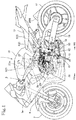
- FIG. 1 is a side elevational view of a motorcycle 1 as a saddle-type vehicle that incorporates a transmission apparatus according to the first embodiment of the present invention.
- forward, rearward, leftward, and rightward directions are defined in accordance with the normal orientations of the motorcycle 1 that include a forward direction along which the motorcycle 1 moves straight ahead.
- the reference letters FR represent a forward direction, RR a rearward direction, LH a leftward direction, and RH a rightward direction.
- the saddle-type motorcycle 1 includes a vehicle body frame 2 having a pair of left and right main frames 3 extending rearward, i.e., wide frames including respective down frame portions 3b, and a pair of central frames 4 (see FIG. 2 ) coupled to respective rear ends of the main frames 3 and bent downward into rear fork pivot portions 4a.
- a seat rail 5 extends rearward and upward from the bent portions of the central frames 4.
- the vehicle body frame 2 also includes a head pipe 3a extending downward from the front ends of the main frames 3.
- a front wheel 7 is rotatably supported on the lower end of a front fork 6 that is steerably supported by the head pipe 3a.
- a steering handle 8 is coupled to the upper end of the front fork 6.
- a rear fork 10 has a front end angularly movably supported by a pivot shaft 9 on the rear fork pivot portions 4a of the central frames 4.
- the rear fork 10 extends rearward and has a rear end on which a rear wheel 11 is rotatably supported by a rear axle, so that the rear wheel 11 is vertically swingable about the pivot shaft 9.
- a power unit 20 is mounted on the vehicle body frame 2 of the motorcycle 1.
- the power unit 20 includes an internal combustion engine 21 having a crankcase 23 and a transmission apparatus 30 ( FIG. 3 ) having a manual multistage transmission (hereinafter referred to as "transmission") 31 integrally housed in a rear portion of the crankcase 23.
- the power unit 20 is suspended from the down frame portions 3b of the main frames 3 and the central frames 4 disposed behind the down frame portions 3b.
- a fuel tank 13 is mounted on the main frames 3 and the central frames 4 above the power unit 20, and a rider's seat 14 is supported on the seat rail 5 behind the fuel tank 13.
- a side stand 15 pivotally mounted on the lower end of the left central frame 4 for angular movement between a lifted position and a lowered position.
- Support brackets 16 have their front ends fixed to the central frames 4 behind the pivot shaft 9 by which the rear fork 10 is supported, and extend rearward.
- Back steps 17 for placing the rider's feet thereon are supported on and project laterally outward from the rear ends of the support brackets 16.
- crankshaft 22 is rotatably supported by the crankcase 23.
- crankcase 23 On the crankcase 23, there are successively stacked a cylinder block 24 and a cylinder head 25 in a substantially upright configuration with the cylinder head 25 being covered with a cylinder head cover 26.
- An intake pipe 27 extends upward through a throttle body 27t from the cylinder head 25, which is tilted forward, of the internal combustion engine 21, and is connected to an air cleaner 27A.
- An exhaust pipe 28 extends forward from the cylinder head 25, is bent downward, then extends rearward, and is connected to a muffler 28M in a rear section of the motorcycle 1.
- crankcase 23 of the internal combustion engine 21 is made up of an upper crankcase member 23U and a lower crankcase member 23L that are vertically separable from each other.
- a hanger 23h extends obliquely rearward and upward from an upper rear portion of the upper crankcase member 23U.
- the hanger 23h has four arms 23ha extending obliquely rearward and upward from the upper crankcase member 23U and arrayed in the transverse directions of the motorcycle 1.
- the four arms 23ha support on their distal ends a hollow cylindrical bearing 23hb extending in the transverse directions of the motorcycle 1, i.e., the leftward and rightward directions thereof.
- the hollow cylindrical bearing 23hb of the hanger 23h is disposed between the left and right central frames 4 of the vehicle body frame 2 and supported by a support shaft 18 extending therethrough and supported by the central frames 4, so that the power unit 20 is suspended by the vehicle body frame 2.
- crankshaft 22 is rotatably supported between and by mating surfaces of left and right bearing walls of the upper crankcase member 23U and the lower crankcase member 23L of the crankcase 23.
- the transmission 31 has a main shaft 32 and a countershaft 33 that extend in the transverse directions of the motorcycle 1, i.e., the leftward and rightward directions thereof.
- the countershaft 33 is also rotatably supported between and by the mating surfaces of the left and right bearing walls of the upper crankcase member 23U and the lower crankcase member 23L of the crankcase 23.
- the main shaft 32 of the transmission 31 is positioned upward and slightly forward of the countershaft 33, and supported by the upper crankcase member 23U.
- the transmission 31 has a group of transmission drive gears 32g rotatably supported on the main shaft 32 and a group of transmission driven gears 33g supported on the countershaft 33, the drive gears 32g and the driven gears 33g being normally held in mesh with each other in pairs corresponding to respective transmission gear ratios.
- the countershaft 33 which is the output shaft of the power unit 20, extends through the left bearing walls and has a projecting left end fitted in an output sprocket 34 that is covered with an output sprocket cover 37 (see FIG. 2 ) on the left side of the crankcase 23.
- the output sprocket 34 is disposed at a position forward of and close to the pivot shaft 9 by which the rear fork 10 is supported on the rear fork pivot portions 4a.
- a drive chain 36 (see FIG. 1 ) is trained around the output sprocket 34 and a driven sprocket 35 fitted coaxially over the rear axle of the rear wheel 11. The output power from the power unit 20 is transmitted from the output sprocket 34 through the drive chain 36 to the rear wheel 11, propelling the motorcycle 1.
- the group of transmission drive gears 32g and the group of transmission driven gears 33g of the transmission 31 are covered with an upper wall 23Ua of the upper crankcase member 23U disposed thereabove.
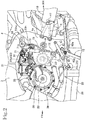
- a rotational speed sensor 80 is mounted on and extends downward through the upper wall 23Ua. The rotational speed sensor 80 is disposed in the vicinity of the rightmost one of the transmission drive gears 32g that rotate in unison with the main shaft 32 (see also FIGS. 6 and 9 ) .
- the rotational speed sensor 80 includes a hollow cylindrical sensor body 80a mounted in and extends through a through mount hole defined in a rotational sensor mount seat 23C of the upper wall 23Ua.
- a lock arm 81 projecting from the sensor body 80a is fastened to the rotational sensor mount seat 23C by a bolt 82 (see FIG. 9 ).
- the rotational speed sensor 80 is a proximity sensor having a detector 80b on its distal end of the sensor body 80a that faces the teeth of the transmission drive gear 32g to detect the rotational speed of the main shaft 32 based on the rotation of the transmission drive gear 32g.
- an AC generator 38 is mounted on the left end of the crankshaft 22 that extends through the left bearing walls for the crankshaft 22.
- the AC generator 38 that projects on the left side of the crankshaft 22 is covered with an ACG cover 39 on the left side of the crankshaft 22.
- a transmission clutch 45 is mounted on the right end of the main shaft 32 that extends through the right bearing walls of the crankcase 23, along a primary driven gear 44 mounted on the main shaft 32.
- the upper crankcase member 23U includes a clutch housing 23Ub that protrudes upward beyond the upper wall 23Ua covering the transmission 31 and that covers the outer circumference of the transmission clutch 45.
- the rotational speed sensor 80 that is mounted on and extends downward through the upper wall 23Ua is disposed on the left side of and along the clutch housing 23Ub protruding upward beyond the upper wall 23Ua.
- the transmission clutch 45 has a right side covered with a clutch cover 46.
- a clutch actuator 47 is mounted on the clutch cover 46 to manually actuate the transmission clutch 45.
- the main shaft 32 and the countershaft 33 are disposed in vertically spaced upper and lower positions behind the crankshaft 22 of the internal combustion engine 21.
- a shift drum 41 is disposed behind the main shaft 32.
- a shift fork shaft 42 is disposed obliquely forward and downward of the shift drum 41 and between the group of transmission driven gears 33g and the shift drum 41.
- the shift fork shaft 42 extends parallel to the main shaft 32 and the countershaft 33.
- a shift fork 43 is rotatably supported on the shift fork shaft 42 and is slidable on and along the shift fork shaft 42 in the leftward and rightward directions.
- the shift fork 43 has an engagement pin 43p slidably engaging in a lead groove 41v defined in the shift drum 41 and a bifurcated fork member engaging shifter gears slidably supported on the main shaft 32 and the countershaft 33.
- the shift fork 43 is axially moved by the engagement pin 43p guided by the lead groove 41v defined in the shift drum 41, moving the shifter gears to bring dog clutches thereon into mesh with each other to make effective the meshing of a pair of transmission gear pair on the main shaft 32 and the countershaft 33, thereby establishing a corresponding transmission gear position.
- the shift drum 41 includes a hollow cylindrical body having a rotational central axis extending in the leftward and rightward directions.
- the hollow cylindrical body of the shift drum 41 has on its left end in the leftward and rightward directions a detectable surface 41f (see FIG. 7 ) that can be detected by a shift drum sensor 48.
- the detectable surface 41f is basically a circumferentially extending cylindrical surface.
- the shift drum sensor 48 corresponds to a neutral switch for detecting a neutral position of the transmission apparatus 30, in particular, in an angular displacement of the shift drum 41.
- the detectable surface 41f of the shift drum 41 includes a projection tip 41fp that projects radially outward from the circumferential surface of the detectable surface 41f.
- the projection tip 41fp is positioned to be directed upward.
- the shift drum sensor 48 is mounted on the upper wall 23Ua of the upper crankcase member 23U that covers the shift drum 41 from above, and is positioned above the detectable surface 41f on the left end of the shift drum 41.
- the upper wall 23Ua of the upper crankcase member 23U has its portion above the detectable surface 41f on the left end of the shift drum 41 adjacent to a proximal end portion of the leftmost one 23hal of the four arms 23ha of the hanger 23h that extends obliquely rearward and upward from the upper wall 23Ua.
- the proximal end portion of the arm 23hal has a recess 23D defined therein that is concave downward and inward from above and a drum sensor mount seat 23A on the bottom wall of the recess 23D.
- the drum sensor mount seat 23A has a through drum sensor mount hole 23Ah defined therein that extends substantially vertically therethrough.
- the through drum sensor mount hole 23Ah has an internally threaded inner circumferential surface.
- the through drum sensor mount hole 23Ah that extends substantially vertically through the drum sensor mount seat 23A has an upper opening surrounded by a substantially horizontal upper end face that serves as a drum sensor mount seat face 23Af of the drum sensor mount seat 23A.
- the shift drum sensor 48 is mounted on the drum sensor mount seat 23A at the bottom wall of the recess 23D defined in the proximal end portion of the leftmost arm 23hal of the hanger 23h that extends from the upper wall 23Ua of the upper crankcase member 23U.
- the shift drum sensor 48 is a limit switch having a drum sensor actuator 48b that is normally biased by a spring to project downward from the distal end of a hollow cylindrical drum sensor body 48a.
- the shift drum sensor 48 is selectively turned on and off in response to advanced and retracted movement of the drum sensor actuator 48b.
- the shift drum sensor 48 includes an enlarged-diameter flange 48f on the drum sensor body 48a.
- a portion of the drum sensor body 48a which is closer to the proximal end, i.e., the upper end, of the shift drum sensor 48 than the enlarged-diameter flange 48f is connected to a harness, whereas a portion of the drum sensor body 48a which is closer to the distal end, i.e., the lower end, of the shift drum sensor 48 than the enlarged-diameter flange 48f has an externally threaded outer circumferential surface.
- the shift drum sensor 48 is mounted in place on the drum sensor mount seat 23A when the externally threaded outer circumferential surface of the portion of the drum sensor body 48a which is closer to the distal end of the shift drum sensor 48 than the enlarged-diameter flange 48f is threaded downward into the internally threaded inner circumferential surface of the through drum sensor mount hole 23Ah defined in the drum sensor mount seat 23A, and the enlarged-diameter flange 48f is held against the substantially horizontal drum sensor mount seat face 23Af of the drum sensor mount seat 23A.
- the portion of the drum sensor body 48a which is closer to the proximal end of the shift drum sensor 48 than the enlarged-diameter flange 48f is disposed outside of the through drum sensor mount hole 23Ah and is almost entirety housed in the recess 23D, whereas the portion of the drum sensor body 48a which is closer to the distal end of the shift drum sensor 48 than the enlarged-diameter flange 48f is mounted in and extends through the through drum sensor mount hole 23Ah.
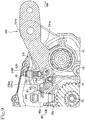
- the drum sensor actuator 48b normally biased to project downward from the drum sensor body 48a is held in contact with the detectable surface 41f on the left end of the shift drum 41 (see FIG. 8 ).
- FIG. 8 depicts the positions of the parts when the transmission apparatus 30 is in the neutral position.
- the projection tip 41fp of the detectable surface 41f of the shift drum 41 is in an upper position, to thereby upwardly retract the drum sensor actuator 48b of the shift drum sensor 48 that is held against the projection tip 41fp to turn on the shift drum sensor 48.
- the projection tip 41fp of the detectable surface 41f is angularly moved out of engagement with the drum sensor actuator 48b of the shift drum sensor 48, which moves downward to turn off the shift drum sensor 48.
- the shift drum sensor 48 can detect the neutral position when the shift drum 41 and hence the transmission apparatus 30 are in the neutral position, to distinguish from the non-neutral position.
- shift spindle 51 that is oriented transversely across the motorcycle 1, i.e., in leftward and rightward directions, is rotatably supported in the crankcase 23 obliquely forward and upward of the shift drum 41.
- the shift spindle 51 and the shift drum 41 have respective rotational central axes extending parallel to each other and are staggered horizontally with respect to each other such that they are kept out of vertical alignment with each other.
- the shift spindle 51 has an upper portion covered with the upper wall 23Ua of the upper crankcase member 23U.
- a ratchet arm 53 is fitted over the right end of the shift spindle 51.
- a shift drum actuating mechanism 52 for transmitting power to intermittently turn the shift drum 41 is provided between the ratchet arm 53 and the right end of the shift drum 41.
- the shift spindle 51 has a flat detectable surface 51f formed as a recess in an arcuate surface that is part of a circular outer circumferential surface of the shift spindle 51 and lying parallel to a plane including the central axis of the shift spindle 51.
- the flat detectable surface 51f is at a position near the right end of the shift spindle 51 over which the ratchet arm 53 of the shift drum actuating mechanism 52 is fitted on the output side, i.e., the right side, of the shift spindle 51.
- a shift spindle sensor 55 is mounted on and extends downward through the upper wall 23Ua of the upper crankcase member 23U that overlies the shift spindle 51 at a position on the left side of and along the clutch housing 23Ub that protrudes upward beyond the upper wall 23Ua.
- the detectable surface 51f of the shift spindle 51 is positioned directly below the shift spindle sensor 55.
- the upper wall 23Ua of the upper crankcase member 23U has a spindle sensor mount seat 23B above the detectable surface 51f in the vicinity of the right end of the shift spindle 51.
- the spindle sensor mount seat 23B has a through spindle sensor mount hole 23Bh defined therein that extends substantially vertically therethrough.
- the through spindle sensor mount hole 23Bh has an internally threaded inner circumferential surface.
- the through spindle sensor mount hole 23Bh that extends substantially vertically through the spindle sensor mount seat 23B has an upper opening surrounded by a substantially horizontal upper end face that serves as a spindle sensor mount seat face 23Bf of the spindle sensor mount seat 23B.
- the shift spindle sensor 55 is a limit switch having a spindle sensor actuator 55b that is normally biased by a spring to project downward from the distal end of a hollow cylindrical spindle sensor body 55a.
- the shift spindle sensor 55 is selectively turned on and off in response to advancing and retracting movement of the spindle sensor actuator 55b.
- the shift spindle sensor 55 includes an enlarged-diameter flange 55f on the spindle sensor body 55a.
- a portion of the spindle sensor body 55a which is closer to the proximal end, i.e., the upper end, of the shift spindle sensor 55 than the enlarged-diameter flange 55f is connected to a harness, whereas a portion of the spindle sensor body 55a which is closer to the distal end, i.e., the lower end, of the shift spindle sensor 55 than the enlarged-diameter flange 55f has an externally threaded outer circumferential surface.
- the shift spindle sensor 55 is mounted in place on the spindle sensor mount seat 23B when the externally threaded outer circumferential surface of the portion of the spindle sensor body 55a which is closer to the distal end of the shift spindle sensor 55 than the enlarged-diameter flange 55f is threaded downward into the internally threaded inner circumferential surface of the through spindle sensor mount hole 23Bh defined in the spindle sensor mount seat 23B, and the enlarged-diameter flange 55f is held against the substantially horizontal spindle sensor mount seat face 23Bf of the spindle sensor mount seat 23B.
- the portion of the spindle sensor body 55a which is closer to the proximal end of the shift spindle sensor 55 than the enlarged-diameter flange 55f, is exposed outwardly, while the portion of the spindle sensor body 55a, which is closer to the distal end of the shift spindle sensor 55 than the enlarged-diameter flange 55f, is mounted in and extends through the through spindle sensor mount hole 23Bh of the spindle sensor mount seat 23B.
- the spindle sensor actuator 55b normally biased to project downward from the spindle sensor body 55a is held in contact with the detectable surface 51f near the left end of the shift spindle 51.
- the spindle sensor actuator 55b that can be vertically advanced and retracted in the shift spindle sensor 55 is slightly displaced forward from the rotational central axis of the shift spindle 51 that is oriented horizontally in the leftward and rightward directions.
- FIG. 9 illustrates the positions of the parts when the shift spindle 51 is not turned, i.e., is in its normal position.
- the spindle sensor actuator 55b of the shift spindle sensor 55 projects in contact with a central area of the flat detectable surface 51f that is inclined, and is advanced to turn on the shift spindle sensor 55.
- the spindle sensor actuator 55b slides against the turning detectable surface 51f and is pushed back or retracted by the turning detectable surface 51f, turning off the shift spindle sensor 55.
- the shift spindle sensor 55 can thus detect turning movement of the shift spindle 51 when the shift spindle 51 is turned.
- the shift spindle 51 is turned about its own axis through a small angular range.
- the vertically movable spindle sensor actuator 55b of the shift spindle sensor 55 is slightly displaced forward from the rotational central axis of the shift spindle 51, the distance by which the spindle sensor actuator 55b is vertically movable is maximized to increase the accuracy with which the shift spindle sensor 55 detects turning movement of the shift spindle 51.
- the shift spindle 51 extends leftward through the crankcase 23 and has a left end portion projecting out of the crankcase 23.
- a support bracket 60 is fixed to the lower end of the left central frame 4 below the projecting left end portion of the shift spindle 51.
- a shift lever 62 has its front end pivotally supported on a shift support shaft 61 projecting from the support bracket 60 and extends rearward from the shift support shaft 61.
- a shift pedal 63 projects leftward from the rear end of the shift lever 62.
- the shift pedal 63 on the shift lever 62 is thus swingable about the shift support shaft 61.
- the shift lever 62 is positioned below the left end of the shift spindle 51 and is operatively coupled to the shift spindle 51 by a link mechanism 70.
- the link mechanism 70 includes a substantially vertical shift rod 72 that interconnects the shift lever 62 and a shift arm 71 fitted over the left end portion of the shift spindle 51 that projects leftward out of the crankcase 23.
- the shift rod 72 has a lower end pivotally connected by a joint pin 62p to a support web 62a projecting downward from the shift lever 62 at a position displaced toward the shift support shaft 61 from the center of the shift lever 62.
- the shift rod 72 has its upper end pivotally connected by a joint pin 71p to the rear end of the shift arm 71 whose front end is fitted over the left end portion of the shift spindle 51.
- the shift rod 72 includes a lost-motion mechanism 73 for transmitting shifting forces from the shift lever 62 through a resilient member incorporated therein.
- the lost-motion mechanism 73 serves to absorb impacts due to engagement of the dogs of the dog clutches of the transmission 31, thereby giving the rider on the motorcycle 1 a smooth gear shift feeling.
- a back step 17 projects from the support bracket 16 on the left central frame 4 behind the shift pedal 63 on the rear end of the shift lever 62 at a position slightly higher than the shift pedal 63.
- the shift lever 62 swings upward about the shift support shaft 61, shifting up the transmission 31.
- the shift lever 62 swings downward about the shift support shaft 61, shifting down the transmission 31.
- the shift lever 62 is swung upward, pushing up the shift rod 72 pivotally coupled to the shift lever 62 by the joint pin 62p.
- the shift arm 71 is now swung upward by the joint pin 71p, turning the shift spindle 51 counterclockwise as viewed in left side elevation as illustrated in FIG. 2 .
- the shift lever 62 is swung downward, pulling down the shift rod 72 pivotally coupled to the shift lever 62 by the joint pin 62p.
- the shift arm 71 is now swung downward by the joint pin 71p, turning the shift spindle 51 clockwise as viewed in left side elevation as illustrated in FIG. 2 .
- the shift drum actuating mechanism 52 angularly moves the shift spindle 51 to change between transmission gear positions of the transmission 51.
- the detectable surface 51f is positioned closely to the ratchet arm 53 on the output side, i.e., the right side, of the shift spindle 51 in view of torsions of the shift spindle 51, whereby the shift spindle sensor 55 can accurately detect angular movement of the shift spindle 51 on the side of the shift drum actuating mechanism 52, i.e., the establishment of a transmission gear position.
- the transmission 31 is reliably detected as being in the neutral position.
- the rotational speed sensor 80 that is disposed in the vicinity of the rightmost one of the transmission drive gears 32g that rotate in unison with the main shaft 32 is located close to the shift spindle sensor 55 disposed above the detectable surface 51f positioned near the right end of the shift spindle 51.
- the upper wall 23Ua of the upper crankcase member 23U that covers the shift drum 41 and the shift spindle 51 from above has the drum sensor mount seat 23A on which the shift drum sensor 48 is mounted and the spindle sensor mount seat 23B on which the shift spindle sensor 55 is mounted.
- the direction in which the shift drum sensor 48 is threaded and mounted in and extends through the through drum sensor mount hole 23Ah defined substantially vertically in the drum sensor mount seat 23A i.e., a central axis direction of the through drum sensor mount hole 23Ah
- the directions in which the drum sensor actuator 48B of the shift drum sensor 48 mounted on the drum sensor mount seat 23A are advanced and retracted, and the directions in which the spindle sensor actuator 55b of the shift spindle sensor 55 mounted on the spindle sensor mount seat 23B are advanced and retracted are substantially vertical directions and parallel to each other.
- a starter motor 90 is disposed on a left portion of the upper crankcase member 23U obliquely rearward and upward of the crankshaft 22.
- the starter motor 90 has its drive shaft 91 projecting rightward and inserted in the crankcase 23.
- the drive shaft 91 has a pinion held in mesh with an enlarged-diameter gear 92g that is integrally coaxial with a small-diameter gear 93 held in mesh with a starter driven gear 94 that is rotatably supported on the main shaft 32 through a one-way clutch, whereby a starter mechanism is made up.
- the transmission apparatus 30 described in detail above according to the first embodiment of the present invention offers the following advantages: As illustrated in FIG. 7 , the direction in which the shift spindle sensor 55 is mounted in and extends through the through spindle sensor mount hole 23Bh in the spindle sensor mount seat 23B is the same as the direction in which the shift drum sensor 48 is mounted in and extends through the through drum sensor mount hole 23Ah in the drum sensor mount seat 23A, so that the shift spindle sensor 55 and the shift drum sensor 48 can be installed on and removed from the upper crankcase member 23U on one external side or the same external side thereof. Therefore, the shift spindle sensor 55 and the shift drum sensor 48 can be installed and removed with ease and can be serviced for excellent maintainability.
- the spindle sensor mount seat 23B and the drum sensor mount seat 23A can be machined in the same direction with ease and hence have excellent machinability.
- the internally threaded inner circumferential surface of the through spindle sensor mount hole 23Bh in the spindle sensor mount seat 23B and the spindle sensor mount seat face 23Bf thereof, and the internally threaded inner circumferential surface of the through drum sensor mount hole 23Ah in the drum sensor mount seat 23A and the drum sensor mount seat face 23Af thereof can easily be machined.
- the spindle sensor mount seat 23B and the drum sensor mount seat 23A are formed in the upper wall 23Ua of the crankcase 23 that covers the shift spindle 51 and the shift drum 41 from above, the shift spindle sensor 55 mounted on and extending through the spindle sensor mount seat 23B and the shift drum sensor 48 mounted on and extending through the drum sensor mount seat 23A are protected by the crankcase 23 from pebbles or the like flipped up from the ground.
- the shift drum sensor 48 mounted on the drum sensor mount seat 23A on the bottom wall of the recess 23D has its portion extending from the flange 48f, disposed inward of the upper wall 23Ua, and its portion including the flange 48f, housed in the recess 23D, so that the shift drum sensor 48 is protected from pebbles or the like flipped up from the ground.
- the shift drum sensor 48 is mounted on a portion of the upper crankcase member 23U near the left end of the shift drum 41 along the rotational axis directions thereof, and the rotational speed sensor 80 is mounted on a portion of the upper crankcase member 23U near the right end of the shift drum 41 along the rotational axis directions thereof, the shift drum sensor 48 and the rotational speed sensor 80 are spaced from each other in the leftward and rightward directions on the respective portions of the upper crankcase member 23U on both ends of the shift drum 41 along the rotational axis directions thereof. Therefore, there is a large space available on the upper crankcase member 23U between the shift drum sensor 48 and the rotational speed sensor 80 for effective use as a space to place other devices therein.
- a transmission apparatus according to a second embodiment of the present invention will be described with reference to FIGS. 10 to 21 .
- the power unit including the transmission apparatus according to a second embodiment and the motorcycle with the power unit mounted thereon are substantially the same as the power unit 20 and the motorcycle 1 in the first embodiment. Therefore, the same reference signs as in the first embodiment will be used in the description of the second embodiment.
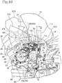
- the power unit 20 includes an internal combustion engine 21 and the transmission apparatus 30 at the front and rear, and a fuel tank 13 is mounted on the transmission apparatus 30 at the rear of the power unit 20.
- the fuel tank 13 is supported with its lower portion located between left and right center frames 4. Between the fuel tank 13 and a cylinder head 25 (and a cylinder head cover 26) in front of the fuel tank 13 are disposed a suction pipe 27 and an air cleaner 27A.
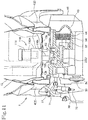
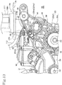
- An upper crankcase member 23U of a crankcase 23 has its upper wall portion 23Ua (see FIG.12 ) covering a group of transmission drive gears 32g and a group of transmission driven gears 33g of the transmission 31. As shown in FIG.11 , a bottom plate 13b of the fuel tank 13 covers the upper wall portion 23Ua from above.
- the bottom plate 13b of the fuel tank 13 is at a height level at which the left and right center frames 4 extend.
- a fuel pump unit 110 On the bottom plate 13b is fixedly supported a fuel pump unit 110 at an intermediate position of the crankcase 23 in the vehicle width direction (approximately a central position with respect to the vehicle width)
- the fuel pump unit 110 has a fuel pump 111 and a cylindrical unit main body 110H provided therein with a fuel passage (not shown) with a fuel pressure adjusting device.
- the fuel pump 111 and the cylindrical unit main body 110H are disposed above the bottom plate 13b and within the fuel tank 13.
- the fuel pump unit 110 has a fuel delivery portion 110t projecting downward from the unit main body 110H out of the fuel tank 13 and below the bottom plate 13b.
- a space defined between the upper wall portion 23Ua of the upper crankcase member 23U and the bottom plate 23b of the fuel tank 13 is narrow. Therefore, the fuel delivery portion 110t of the fuel pump unit 110 projecting downward from the bottom plate 13b, and a fuel supply hose 112 (see FIG. 10 ) are located close to the upper wall portion 23Ua of the upper crankcase member 23U.
- the fuel pump 111 of the fuel pump unit 110 operates to suck fuel in the fuel tank 13 by way of an area on the bottom plate 23b, and fuel supplied from the fuel pump 111 is sent by way of a fuel supply passage into the fuel delivery portion 110t. The fuel is then caused to flow through the fuel supply hose 112 to a fuel injection valve 113 (see FIG.10 ) provided in the intake system of the engine 21.
- a shift spindle 51 is subjected to rotary displacement by way of a link mechanism 70. Then, the rotary displacement of the shift spindle 51 causes a shift drum 41 to make rotary movement by way of a shift drum actuating mechanism 52. The rotary movement of the shift drum 41 is transmitted to a shifter gear of a transmission 31 through a shift fork 43 to select an effectively working transmission gear pair out of a plurality of intermeshing transmission gear pairs.
- a link mechanism 70 is constituted by connecting a shift lever 62 at a lower level to a shift arm 71 projecting from the left end of a shift spindle 51 beyond the crankcase 23, by way of a shift rod 72 directed substantially vertically.
- the shift rod 72 includes a lost motion mechanism 73 for transmitting operating forces by way of an elastic member.
- the lost motion mechanism 73 operates to absorb impacts due to engagement of the dogs of the dog clutches of the transmission 31, thereby giving the rider on the motorcycle 1 a smooth gear shift feeling.
- the lost motion mechanism 73 has a shift stroke sensor 75 for detecting expansion and contraction of the shift rod 72 as a result of operation of the lost motion mechanism 73.
- the lost motion mechanism 73 includes a coil spring interposed between one longitudinal end of the mechanism and the other longitudinal end, so as to be able to expand and contract.
- the shift stroke sensor 75 is a linear stroke sensor capable of detecting relative displacement of the one and the other longitudinal ends of the lost motion mechanism 73.
- the shift stroke sensor 75 is means for detecting an initial change in length of the shift rod 72 of the link mechanism 70, by means of the lost motion mechanism 73, prior to rotary movement of the shift spindle 51 by the shifting action, and the shift stroke sensor 75 can thus detect the shifting action to distinguish whether the shifting action is an upshifting action or a downshifting action.
- a first shift spindle sensor 55 and a second shift spindle sensor 155 are mounted on an upper wall 23Ua of the upper crankcase member 23U covering the shift spindle from above.
- the first and second shift spindle sensors 55 and 155 operate to detect rotational motion of the shift spindle 51.
- the first and second shift spindle sensors 55 and 155 are positioned to be spaced apart in the direction along the longitudinal axis of the shift spindle 51.
- the first and second shift spindle sensors 55 and 155 may be identical members in construction to save cost.
- the upper wall 23Ua of the upper crankcase member 23U has a transmission clutch accommodating part 23Ub, which is located adjacent to the right end of the shift spindle 51.
- a spindle sensor mount seat 23B is provided on the upper wall 23Ua at a position adjacent to the transmission clutch accommodating part 23Ub.
- the spindle sensor mount seat 23B is formed therein with a spindle sensor mount through hole 23Bh in which the first shift spindle sensor 55 is vertically inserted and screw-engaged therein.
- a spindle sensor mount seat 123B is provided on the upper wall 23Ua at a location spaced apart leftward from the spindle sensor mount seat 23B.
- the spindle sensor mount seat 123B is formed therein with a spindle sensor mount through hole 123Bh in which the second shift spindle sensor 155 is vertically inserted and screw-engaged therein.
- a shift drum sensor 48 is provided to detect rotary movement of the shift drum 41, as in the first embodiment of the invention.
- the shift drum sensor 48 is inserted and screw-engaged in a through drum sensor mount hole 23Ah (see FIG. 7 ) extending at right angles to a drum sensor mount seat on the upper wall portion 23Ua (see FIG. 12 ).
- the direction in which the shift drum sensor 48 extends in the through drum sensor mount hole 23Ah is a direction parallel to the directions in which the first and second shift spindle sensors 55 and 155 extend in the respective first and second spindle sensor mount through holes 23Bh and 123Bh.
- first and second shift spindle sensors 55 and 155, together with the shift drum sensor 48 can be mounted on and dismounted from the outer surface of the upper crankcase member 23U, in the same directions, whereby the mounting and dismounting operations of the first and second shift spindle sensors 55 and 155 and the shift drum sensor 48 can be made easy with improved maintainability.
- the spindle sensor mount through holes 23Bh and 123Bh are directed in the same direction as the through drum sensor mount hole 23Ah, the machining operations on the spindle sensor mount seats 23B and 123B and on the drum sensor mount seat 23A can be made on the same side, which makes it easy to perform the machining operations with resultant excellent machinability.
- the above arrangement makes easy the machining operations on the female screws of the spindle sensor mount holes 23Bh and 123Bh in the spindle sensor mount seats 23B and 123B, as well as on the spindle sensor mount seat faces 23Bf and 123Bf.
- the above arrangement also makes easy the machining operations on the female screw of the drum sensor mount hole 23Ah in the drum sensor mount seat 23A, as well as on the drum sensor mount seat face 23Af.
- the first and second shift spindle sensors 55 and 155 are limit switches having spindle sensor bodies 55a and 155a from which spindle sensor actuators 55b and 155b are urged to project under spring forces, respectively.
- the first and second shift spindle sensors 55 and 155 are made on and off by retracting and advancing movements of the spindle sensor actuators 55b and 155b.
- the projecting spindle sensor actuator 55b is positioned directly above a flat detectable surface 51f formed near the right end of the shift spindle 51.
- the projecting spindle sensor actuator 155b is positioned directly above a flat detectable surface 51g formed near the left end of the shift spindle 51.
- the spindle sensor actuator 55b capable of advancing and retracting movement along the length of the first shift spindle sensor 55 is offset somewhat rearward relative to the rotational center axis of the shift spindle 51 oriented horizontally.
- the spindle sensor actuator 155b capable of advancing and retracting movement along the length of the second shift spindle sensor 155 is offset somewhat forward relative to the rotational center axis of the shift spindle 51 oriented horizontally.
- the rearward and forward offset amounts of the spindle sensor actuators 55b and 155b, relative to the rotational center axis of the shift spindle 51, are approximately equal.
- FIG. 15 shows a section of the upper crankcase member 23U covering the shift drum 41 and the shift spindle 51 from above, the section being taken at the location of the second shift spindle sensor 155 and being viewed from the left side.
- FIG. 17 shows a perspective view of the shift spindle 51 and the first and second shift spindle sensors 55 and 155, illustrating positional relation of the first and second shift spindle sensors 55 and 155 relative to the shift spindle 51.
- FIG. 18 shows a section of the shift spindle 51, taken at the position of the second shift spindle sensors 155.
- the section is viewed from the left side of the shift spindle 51, while the shift spindle 51 and the first and second shift spindle sensors 55 and 155 are in the relative positions shown in FIG. 17 .
- FIGS. 15 to 18 show a normal state in which shifting action is not made and the shift spindle 51 is not rotated
- the flat detectable surface 51f on the right side of the shift spindle 51, to which surface 51f the downwardly protruding spindle sensor actuator 55b of the first shift spindle sensors 55 is directed is not parallel to, and makes an angle relative to the flat detectable surface 51g on the left side of the shift spindle 51, to which surface 51g the downwardly protruding spindle sensor actuator 155b of the second shift spindle sensors 155 is directed.
- the flat detectable surface 51f on the upper surface of the right side of the horizontally directed shift spindle 51 faces the downwardly protruding and rearwardly offset spindle sensor actuator 55b of the first shift spindle sensors 55 and is downwardly inclined to the rear at an angle of 16° , for example.
- the flat detectable surface 51g on the upper surface of the left side of the horizontally directed shift spindle 51 faces the downwardly protruding and forwardly offset spindle sensor actuator 155b of the second shift spindle sensors 155 and is downwardly inclined to the front at an angle of 16°, for example.
- the spindle sensor actuator 55b of the first shift spindle sensors 55 is located adjacent to the flat detectable surface 51f but not in contact with the detectable surface 51f, so that the spindle sensor actuator 55b is in the OFF state.
- the spindle sensor actuator 155b of the second shift spindle sensors 155 is located adjacent to the flat detectable surface 51g but not in contact with the detectable surface 51g, so that the spindle sensor actuator 155b is in the OFF state.
- first and second shift spindle sensor actuators 55b and 155b of the first and second shift spindle sensors 55 and 155 are in the OFF state when these actuators 55b and 155b are in the advanced state.
- the detectable surface 51f When the counterclockwise rotation of the shift spindle 51 is finished, that is, at the time the upshifting is established, the detectable surface 51f, downwardly inclining to the rear, takes a horizontal attitude as a result of the counterclockwise rotation, as shown in FIG. 19 . Consequently, a rear end 51fr of the detectable surface 51f is brought into contact with the shift spindle sensor actuators 55b of the first shift spindle sensor 55, to thereby press or push up the shift spindle sensor actuators 55b. This brings the first shift spindle sensor 55 in the ON state.
- the detectable surface 51g which has faced obliquely forward in the state of FIG. 18 , is caused to have an increased inclination toward the front as the shift spindle 51 rotates counterclockwise.
- the detectable surface 51g does not reach the shift spindle sensor actuators 155b of the second shift spindle sensor 55, so that the second shift spindle sensor 55 remains in the OFF state.
- the first spindle sensor 55 is brought in the ON state, thus ensuring detection of the completion of the upshifting operation.
- the detectable surface 51g When the clockwise rotation of the shift spindle 51 is finished, that is, at the time the downshifting is established, the detectable surface 51g, downwardly inclining to the front, takes a horizontal attitude as a result of the clockwise rotation, as shown in FIG. 20 . Consequently, a rear end 51gr of the detectable surface 51g is brought into contact with the shift spindle sensor actuators 155b of the second shift spindle sensor 155, to thereby press or push up the shift spindle sensor actuators 155b. This brings the second shift spindle sensor 155 in the ON state.
- the detectable surface 51f downwardly inclining to the rear, is caused to have an increased inclination as the shift spindle 51 rotate clockwise. However, the detectable surface 51f does not reach the shift spindle sensor actuator 55b of the first shift spindle sensor 55, so that the first shift spindle sensor 55 is maintained in the OFF state.
- the second spindle sensor 55 is brought in the ON state, thus ensuring detection of the completion of the downshifting operation.
- the motorcycle 1 is installed with a quick-shifting mechanism Q for enabling a speed change operation without the clutching action, by lowering the output of the internal combustion engine 21.
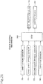
- the quick-shifting mechanism Q includes an ECU (electronic control unit) 200 shown in FIG. 21 .
- the ECU 200 operates to control a fuel injection valve 113 and ignition device 201 to lower the output of the internal combustion engine 21.
- detection signals are input to the ECU 200 from the shift stroke sensor 75, the first shift spindle sensor 55 and the second shift spindle sensor 155.
- the ECU 200 sends control signals to the fuel injection valve 113 and the ignition device 201, to control the motorcycle, based on the detection signals input from the shift stroke sensor 75, the first shift spindle sensor 55 and the second shift spindle sensor 155.
- the ECU 200 operates, in particular, when the shift stroke sensor 75 detects initial movement of the link mechanism 70 as a result of an upshifting operation, to lower the output of the internal combustion engine 21 by controlling the fuel injection valve 113 to stop fuel supply and by controlling the ignition device 201 to delay the ignition timing.
- Lowering the output of the engine 21 enables smooth disconnection of the dog clutch of the transmission by reducing the torque transmitted through the transmission without the operation of the transmission clutch 45, whereby speed change operation can be performed smoothly and quickly.
- the first shift spindle sensor 55 When the shift spindle 51 is rotated by means of the link mechanism 70 for upshifting operation and the upshifting is established with the rotary movement of the shift spindle 51 finished, the first shift spindle sensor 55 is put in the ON state. When the first shift spindle sensor 55 is put in the ON state, the ECU 200 operates to stop the operation of lowering the output of the engine 21 to recover the engine output quickly.
- the action of the kick-down is judged by the ECU 200 based on the signal from the shift stroke sensor 75 and the signal from the throttle sensor 160, and the ECU 200 controls the fuel injection valve 113 to stop fuel supply and the ignition device 201 to delay the ignition timing, to thereby lower the output of the engine 21.
- a smooth and quick speed change operation can be performed without operating the transmission clutch.
- the lowering of the output of the engine 21 is released to recover the engine output, when the second shift spindle sensor 155 is brought in the ON state as a result of completion of the rotary movement of the shift spindle 51, which means establishment of the state of downshift.
- the transmission apparatus according to the second embodiment of the invention as described above provides the advantageous effects as follows.
- the rotary movement of the shift spindle 51 is detected not only by the first shift spindle sensor 55 but also by the second shift spindle sensor 155. Therefore, the rotary movement of the shift spindle 51 can be detected precisely because of the use of the two shift spindle sensors 55 and 155.
- the first shift spindle sensor 55 operates to detect rotary movement of the shift spindle 51 in the case of upshift
- the second shift spindle sensor 155 operates to detect rotary movement of the shift spindle 51 in the case of downshift.
- the first shift spindle sensor 55 may be made to detect downshifting action and the second shift spindle sensor 155 may be to detect upshifting action.
- the fuel pump unit 110 (shown in dotted pattern) fixed to the bottom plate 13b of the fuel tank 13 disposed above the crankcase 23 has at least portion thereof overlapping vertically with the first and second shift spindle sensors 55 and 155, with respect to the longitudinal and widthwise directions of the vehicle.
- the fuel delivery portion 110t projecting downward from a central region of the pump unit 110 is located between the first and second shift spindle sensors 55 and 155, with respect to the direction of the length of the shift spindle 51. Therefore, the fuel delivery portion 110t can be set without interference with the first and second shift spindle sensors 55 and 155, whereby the fuel pump unit 110 can be installed at a lowered position as possible, close to the crankcase 23.
- the motorcycle 1 is mounted thereon the quick-shifting mechanism Q for enabling a speed change operation without the clutching action by lowering the output of the internal combustion engine 21.
- the quick-shifting mechanism Q is operated by detection signal from the shift stroke sensor 75 detecting initial movement of the link mechanism 70 and by detection signals from the first and second shift spindle sensors 55 and 155.
- the quick-shifting mechanism Q performs reduction of the output of the internal combustion engine base on the signal from the shift stroke sensor 75 and performs release of the engine output reduction based on signals from the first and second shift spindle sensors 55 and 155. For this reason, the quick-shifting mechanism Q enables engine output control at a proper timing, as well as a reduction in transmission torque, with resultant smooth disengagement of the dog clutch in the transmission and with resultant smooth and quick speed change of the transmission.
- the transmission apparatus 30 changes transmission gear positions when the shift lever 62 is operated to turn the shift spindle 51 through the link mechanism 70.
- the shift spindle may, for example, be turned by an actuator such as an electric motor to cause the transmission apparatus 30 to change transmission gear positions, as disclosed in JP 6069774 referred to above.
- the detectable surface 51f of the shift spindle 51 is not limited to the illustrated flat shape, but may be formed as an uneven surface.
Landscapes
- Engineering & Computer Science (AREA)
- General Engineering & Computer Science (AREA)
- Mechanical Engineering (AREA)
- Chemical & Material Sciences (AREA)
- Combustion & Propulsion (AREA)
- Transportation (AREA)
- Gear-Shifting Mechanisms (AREA)
Abstract
Description
- The present invention relates to a transmission apparatus incorporated in a power unit mounted on a small-size vehicle.
- Transmission apparatus of the type described generally have a normally meshing type transmission that operates to achieve a desired transmission gear position by rotationally moving a shift spindle in response to a gear shifting action, converting the rotary motion of the shift spindle into intermittent rotary motion of a shift drum with a shift drum actuating mechanism, axially moving a shift fork with the intermittent rotary motion of the shift drum, and moving a shift gear of the transmission with the axial motion of the shift fork, thereby selecting an effectively working transmission gear pair out of a plurality of intermeshing transmission gear pairs.
- Among those transmission apparatus, there is a transmission apparatus having a neutral switch or shift drum sensor for detecting the rotational motion of the shift drum and a shifter switch or shift spindle sensor for detecting the rotational motion of the shift spindle in order to reliably determine whether or not the transmission is in a neutral position (see, for example, Japanese Patent No.
6 069 774 JP 6069774 - In the transmission apparatus disclosed in
JP 6069774 - In the transmission apparatus disclosed in
JP 6069774 FIG. 6 ) of a transmission control system. Meanwhile, the shifter switch or shift spindle sensor is not illustrated in a side elevational view (FIG. 2 ) of a power unit and a plan view (FIG. 3 ) of the power unit. - Referring to
FIGS. 2 and3 ofJP 6069774 upper crankcase member 32. - As illustrated in
FIGS. 1 through 5 ofJP 6069774 upper crankcase member 32. However, a shifter switch 135 is not illustrated. - The shifter switch 135 is not illustrated on an upper surface 32a of the
upper crankcase member 32 either. - In the transmission apparatus disclosed in
JP 6069774 upper crankcase member 32 in view of the position of the shift spindle, denoted by 84, illustrated inFIG. 2 . However the shifter switch 135 is not present on the rear surface 32b of theupper crankcase member 32, and any structure is not disclosed wherein the mount seat face for the shifter switch 135 and the mount seat face for the neutral switch S4 lie parallel to each other. - Therefore, the neutral switch and the shifter switch are installed perpendicularly on and removed perpendicularly from the respective mount seat faces in different directions, and hence cannot be well serviced when they are attached to and detached from their mount seat faces.
- Furthermore, when the mount seat faces for the neutral switch and the shifter switch are machined, their machinability is poor.
- The present invention has been made in view of the above problems. It is an object of at least the preferred embodiments of the present invention to provide a transmission apparatus that includes a shift spindle sensor and a shift drum sensor that can be easily attached to and detached from their mount seats and that can be well serviced for excellent maintainability, and that allows the mount seats respectively for the shift spindle sensor and the shift drum sensor to be machined with ease and excellent machinability.
- There is provided in accordance with the present invention a transmission apparatus incorporated in a power unit mounted on a small-size vehicle and including a shift spindle rotatable in response to a gear shifting action, a shift drum rotatable through a shift drum actuating mechanism by rotation of the shift spindle, and a case covering the shift spindle and the shift drum, the transmission apparatus comprising: a shift spindle sensor for detecting rotary movement of the shift spindle; and a shift drum sensor for detecting rotary movement of the shift drum; wherein the shift spindle sensor is mounted in and extends through a through spindle sensor mount hole defined in a spindle sensor mount seat formed on a predetermined portion of the case; the shift drum sensor is mounted in and extends through a through drum sensor mount hole defined in a drum sensor mount seat formed on a predetermined portion of the case; and a direction in which the shift spindle sensor is mounted in and extends through the through spindle sensor mount hole is same as a direction in which the shift drum sensor is mounted in and extends through the through drum sensor mount hole.
- With this arrangement, since the direction in which the shift spindle sensor is mounted in and extends through the through spindle sensor mount hole in the spindle sensor mount seat formed in the predetermined portion of the case is same as the direction in which the shift drum sensor is mounted in and extends through the through drum sensor mount hole in the drum sensor mount seat formed in the predetermined portion of the case, the shift spindle sensor and the shift drum sensor can be installed on and removed from the case on one external side thereof. Therefore, the shift spindle sensor and the shift drum sensor can be installed and removed with ease and can be serviced for excellent maintainability.
- Furthermore, as the through spindle sensor mount hole and the through drum sensor mount hole are oriented in the same direction, the spindle sensor mount seat and the drum sensor mount seat can be machined in the same direction with ease for excellent machinability.
- In a preferred embodiment of the invention, the shift spindle sensor is a limit switch having a spindle sensor actuator projecting from a spindle sensor body, and is capable of selectively being turned on and off in response to advancing and retracting movement of the spindle sensor actuator which is held in contact with a detectable surface on a part of an outer circumferential surface of the shift spindle.
- The shift drum sensor may be a limit switch having a drum sensor actuator projecting from a drum sensor body, and may be capable to be selectively turned on and off in response to advancing and retracting movement of the drum sensor actuator which is held in contact with a detectable surface on a part of an outer circumferential surface of the shift drum.
- Further, directions of advancing and retracting movement of the spindle sensor actuator and directions of advancing and retracting movement of the drum sensor actuator may be the same as each other.
- With the above arrangement, inasmuch as the directions in which the spindle sensor actuator is advanced and retracted, and the directions in which the drum sensor actuator is advanced and retracted are the same as each other, accelerations due to the vibrations of the power unit act equally on the spindle sensor actuator and the drum sensor actuator, and any differences due to disturbances between timings at which the shift spindle sensor and the shift drum sensor detect operating states of the transmission apparatus are minimized.
- In a preferred embodiment of the invention, the shift spindle and the shift drum have respective rotational central axes extending parallel to each other and are staggered horizontally with respect to each other such that they are kept out of vertical alignment with each other.
- The spindle sensor mount seat and the drum sensor mount seat may be formed on an upper wall of the case that covers the shift spindle and the shift drum from above.
- With the above arrangement, since the spindle sensor mount seat and the drum sensor mount seat are formed on the upper wall of the case that covers the shift spindle and the shift drum from above, the shift spindle sensor mounted on and extending through the spindle sensor mount seat and the shift drum sensor mounted on and extending through the drum sensor mount seat are protected by the crankcase from pebbles or the like flipped up from the ground.
- In a preferred embodiment of the invention, at least one of the spindle sensor mount seat and the drum sensor mount seat is disposed on a bottom wall of a recess defined in the case and extending inward from an outer surface of the case.
- With the above arrangement, since at least one of the spindle sensor mount seat and the drum sensor mount seat is disposed on a bottom wall of a recess defined in the case and extending inward from an outer surface of the case, at least one of the shift spindle sensor and the shift drum sensor, which is mounted on the mount seat on the bottom wall of the recess, is at least partly housed in the recess and protected from pebbles or the like.
- In a further preferred embodiment of the invention, the power unit is suspended from a vehicle body frame of the small-size vehicle through a projecting hanger of the case.
- The shift drum sensor may be mounted on the drum sensor mount seat on the bottom wall of the recess defined in the hanger.
- With the above arrangement, since the shift drum sensor is mounted on the drum sensor mount seat on the bottom wall of the recess defined in the projecting hanger of the case, the shift drum sensor is at least partly housed in the recess in the hanger, and is reliably protected by the hanger from pebbles or the like and easily kept out of interference with other devices.
- In a still further embodiment of the invention, a rotational speed sensor for detecting rotation of a transmission gear rotatably supported on a transmission gear shaft of the transmission apparatus is mounted in and extends through the case at a position closer to either one of the shift spindle sensor and the shift drum sensor than to the other of the shift spindle sensor and the shift drum sensor.
- In the above arrangement, inasmuch as the rotational speed sensor is mounted on the case at a position closer to either one of the shift spindle sensor than to the shift drum sensor, the rotational speed sensor and either one of the shift spindle sensor and the shift drum sensor are put closely together, creating a space on the case that can effectively be used to place other devices therein.
- In an embodiment of the invention, the shift drum sensor is mounted on the drum sensor mount seat formed on a portion of the case adjacent to one end of the shift drum in rotational central axis directions thereof.
- Further, the rotational speed sensor may be mounted on a portion of the case adjacent to the other end, which is opposite to the one end, of the shift drum in the rotational central axis directions thereof.
- With the above arrangement, since the shift drum sensor is mounted on the drum sensor mount seat formed on a portion of the case adjacent to one end of the shift drum in the rotational axis directions thereof, and the rotational speed sensor is mounted on a portion of the case adjacent to the other end, which is opposite to the one end of the shift drum, in the rotational axis directions thereof, the shift drum sensor and the rotational speed sensor are spaced from each other on the respective portions of the case on both ends of the shift drum in the rotational axis directions thereof. Therefore, there is a large space available on the case between the shift drum sensor and the rotational speed sensor for effective use as a space to place other devices therein.
- In a preferred embodiment of the invention, at a position separated from the shift spindle sensor along a longitudinal direction of the shift spindle, a second shift spindle sensor for detecting rotary movement of the shift spindle is provided on the case.
- According to the above configuration, since rotational movement of the shift spindle is detected not only by the shift spindle sensor but also by the second shift spindle sensor, rotational movement of the shift spindle is detected by the two shift spindle sensors, whereby detection of the rotational movement of the shift spindle can be detected precisely.
- In a preferred embodiment of the invention, the first-named shift spindle sensor is for detecting rotary movement of the shift spindle in one direction, and the second shift spindle sensor is for detecting rotary movement of the shift spindle in the other direction.
- According to the above configuration, the first named shift spindle sensor and the second shift spindle sensor operate to detect rotary movements in mutually different directions, whereby rotary movements in both the upshifting and downshifting directions can be detected in a distinguished way.
- In a further preferred embodiment of the invention, the small-size vehicle includes center frames extending rearward from left and right main frames extending from a head pipe; a fuel tank is mounted between the center frames; a fuel pump unit having a fuel pump with a fuel delivery portion is mounted on a bottom plate of the fuel tank with the fuel delivery portion protruding downward from the bottom plate; the fuel tank is positioned above the case; and at least a portion of the fuel pump unit is in vertically overlapping relation with the first-named shift spindle sensor and the second shift spindle sensor.
- According to the above configuration, at least a portion of the fuel pump unit mounted on the bottom plate of the fuel pump and disposed above the case is in overlapping relation with the first-named shift spindle sensor and the second shift spindle sensor. Therefore, the downwardly protruding fuel delivery portion in the central portion of the fuel pump unit is positioned between the two shift spindle sensors with respect to the length direction of the shift spindle and can avoid interference with the two shift spindle sensors. As a result, the fuel pump unit can be installed at a lowered level as close as possible to the case, whereby the bottom plate of the fuel tank, on which the fuel pump unit is mounted, can be lowered with resultant increase of the volume of the fuel tank.
- In a preferred embodiment of the invention, the small-size vehicle is mounted thereon with a quick-shifting mechanism for lowering output of the engine to perform speed change operation without transmission clutch operation; the shift spindle is configured to rotate by a shifting operation of a shift lever by way of a link mechanism; a shift sensor is provided for detecting initial movement of the link mechanism due to a shifting action; and the quick-shifting mechanism is operable based on a detection signal from the shift sensor and on detection signals from the first-named shift spindle sensor and the second shift spindle sensor.
- According to the above configuration, the small-size vehicle is mounted thereon with a quick-shifting mechanism for lowering output of the engine to perform speed change operation without transmission clutch operation, and the quick-shifting mechanism operates based on a detection signal from the shift sensor for detecting initial movement of the link mechanism due to a shifting action and based on detection signals from the first-named shift spindle sensor and the second shift spindle sensor. The quick-shifting mechanism thus performs engine output reduction upon detecting initial movement of speed change action. The quick-shifting mechanism then operates to cease the engine output reduction upon detection signals from the first-named shift spindle sensor and the second shift spindle sensor. The quick-shifting mechanism thus operates to perform engine output control at a proper timing without transmission clutch operation to lower the transmission torque and to smoothly disconnect the transmission dog clutch, ensuring smooth and quick speed change operation in the transmission.
- According to the present invention, the direction in which the shift spindle sensor is mounted in and extends through the through spindle sensor mount hole in the spindle sensor mount seat formed in the predetermined portion of the case is same as the direction in which the shift drum sensor is mounted in and extends through the through drum sensor mount hole in the drum sensor mount seat formed in the predetermined portion of the case. Consequently, the shift spindle sensor and the shift drum sensor can be installed on and removed from the case on one external side thereof. Therefore, the shift spindle sensor and the shift drum sensor can be installed and removed with ease and can be serviced for excellent maintainability.
- Further, as the through spindle sensor mount hole and the through drum sensor mount hole are oriented in the same directions, the spindle sensor mount seat and the drum sensor mount seat can be machined in the same direction with ease and hence have excellent machinability.
- Certain preferred embodiments of the invention will now be described by way of example only, and with reference to the accompanying drawings, in which:
-
FIG. 1 is a side elevational view of a motorcycle mounted thereon with a transmission apparatus according to a first embodiment of the present invention; -
FIG. 2 is a side elevational view of a power unit mounted on the motorcycle illustrated inFIG. 1 ; -
FIG. 3 is a plan view of the power unit illustrated inFIG. 2 ; -
FIG. 4 is a fragmentary side elevational view of a rear portion of the power unit illustrated inFIG. 2 ; -
FIG. 5 is a fragmentary perspective view of the rear portion of the power unit illustrated inFIG. 2 ; -
FIG. 6 is a fragmentary perspective view depicting the internal structure of the transmission apparatus in the rear portion of the power unit, with a crankcase omitted from illustration; -
FIG. 7 is a sectional view of the power unit, partly cut away, taken along line VIII-VIII ofFIG. 3 , immediately prior to the installation of a shift drum sensor and a shift spindle sensor; -
FIG. 8 is a sectional view of the power unit taken along line VIII-VIII ofFIG. 3 ; -
FIG. 9 is a sectional view of the power unit taken along line IX-IX ofFIG. 3 ; -
FIG. 10 is a side elevational view of a motorcycle mounted thereon with a transmission apparatus according to a second embodiment of the present invention; -
FIG. 11 is a sectional view showing a principal portion of the motorcycle, taken along line XI-XI ofFIG. 10 ; -
FIG. 12 is a plan view of a power unit mounted on the motorcycle; -
FIG. 13 is a rear side view of the power unit; -
FIG. 14 is a perspective view of the power unit as viewed from the rear side; -
FIG. 15 is a sectional view of a portion of the power unit; -
FIG. 16 is a perspective view of the power unit as seen from the rear side, showing the inside of the power unit with a crank case removed; -
FIG. 17 is a perspective view showing positional relation of first and second shift spindle sensors relative to a shift spindle; -
FIG. 18 is a left side view, partly in section, showing the first and second shift spindle sensors relative to the shift spindle, which is in a normal state; -
FIG. 19 is a similar left side view showing the first and second shift spindle sensors relative to the shift spindle, which is operated for upshifting operation; -
FIG. 20 is a similar left side view when the shift spindle is operated for downshifting operation; and -
FIG. 21 is a block diagram of a quick-shifting mechanism. - A transmission apparatus according to a first embodiment of the present invention will be described in detail below with reference to
FIGS. 1 through 9 . -
FIG. 1 is a side elevational view of amotorcycle 1 as a saddle-type vehicle that incorporates a transmission apparatus according to the first embodiment of the present invention. - In the present description, forward, rearward, leftward, and rightward directions, and similar directional expressions are defined in accordance with the normal orientations of the
motorcycle 1 that include a forward direction along which themotorcycle 1 moves straight ahead. In the drawings, the reference letters FR represent a forward direction, RR a rearward direction, LH a leftward direction, and RH a rightward direction. - As illustrated in
FIG. 1 , the saddle-type motorcycle 1 includes avehicle body frame 2 having a pair of left and rightmain frames 3 extending rearward, i.e., wide frames including respective downframe portions 3b, and a pair of central frames 4 (seeFIG. 2 ) coupled to respective rear ends of themain frames 3 and bent downward into rearfork pivot portions 4a. - A
seat rail 5 extends rearward and upward from the bent portions of thecentral frames 4. - The
vehicle body frame 2 also includes ahead pipe 3a extending downward from the front ends of themain frames 3. A front wheel 7 is rotatably supported on the lower end of afront fork 6 that is steerably supported by thehead pipe 3a. Asteering handle 8 is coupled to the upper end of thefront fork 6. - A
rear fork 10 has a front end angularly movably supported by apivot shaft 9 on the rearfork pivot portions 4a of thecentral frames 4. Therear fork 10 extends rearward and has a rear end on which arear wheel 11 is rotatably supported by a rear axle, so that therear wheel 11 is vertically swingable about thepivot shaft 9. - A
power unit 20 is mounted on thevehicle body frame 2 of themotorcycle 1. Thepower unit 20 includes aninternal combustion engine 21 having acrankcase 23 and a transmission apparatus 30 (FIG. 3 ) having a manual multistage transmission (hereinafter referred to as "transmission") 31 integrally housed in a rear portion of thecrankcase 23. Thepower unit 20 is suspended from thedown frame portions 3b of themain frames 3 and thecentral frames 4 disposed behind thedown frame portions 3b. - A
fuel tank 13 is mounted on themain frames 3 and thecentral frames 4 above thepower unit 20, and a rider'sseat 14 is supported on theseat rail 5 behind thefuel tank 13. - A side stand 15 pivotally mounted on the lower end of the left
central frame 4 for angular movement between a lifted position and a lowered position. -
Support brackets 16 have their front ends fixed to thecentral frames 4 behind thepivot shaft 9 by which therear fork 10 is supported, and extend rearward. Back steps 17 for placing the rider's feet thereon are supported on and project laterally outward from the rear ends of thesupport brackets 16. - The
internal combustion engine 21, which is a water-cooled 4-cylinder, 4-stroke-cycle internal combustion engine, is mounted on themotorcycle 1 and has a crankshaft 22 (FIG. 2 ) oriented transversely across themotorcycle 1, i.e., in leftward and rightward directions. - The
crankshaft 22 is rotatably supported by thecrankcase 23. On thecrankcase 23, there are successively stacked acylinder block 24 and acylinder head 25 in a substantially upright configuration with thecylinder head 25 being covered with acylinder head cover 26. - An
intake pipe 27 extends upward through athrottle body 27t from thecylinder head 25, which is tilted forward, of theinternal combustion engine 21, and is connected to anair cleaner 27A. - An
exhaust pipe 28 extends forward from thecylinder head 25, is bent downward, then extends rearward, and is connected to amuffler 28M in a rear section of themotorcycle 1. - As illustrated in
FIG. 4 , thecrankcase 23 of theinternal combustion engine 21 is made up of anupper crankcase member 23U and alower crankcase member 23L that are vertically separable from each other. Ahanger 23h extends obliquely rearward and upward from an upper rear portion of theupper crankcase member 23U. - As illustrated in
FIGS. 4 and5 , thehanger 23h has four arms 23ha extending obliquely rearward and upward from theupper crankcase member 23U and arrayed in the transverse directions of themotorcycle 1. The four arms 23ha support on their distal ends a hollow cylindrical bearing 23hb extending in the transverse directions of themotorcycle 1, i.e., the leftward and rightward directions thereof. - As illustrated in
FIG. 2 , the hollow cylindrical bearing 23hb of thehanger 23h is disposed between the left and rightcentral frames 4 of thevehicle body frame 2 and supported by asupport shaft 18 extending therethrough and supported by thecentral frames 4, so that thepower unit 20 is suspended by thevehicle body frame 2. - As illustrated in
FIG. 4 , thecrankshaft 22 is rotatably supported between and by mating surfaces of left and right bearing walls of theupper crankcase member 23U and thelower crankcase member 23L of thecrankcase 23. Thetransmission 31 has amain shaft 32 and acountershaft 33 that extend in the transverse directions of themotorcycle 1, i.e., the leftward and rightward directions thereof. Thecountershaft 33 is also rotatably supported between and by the mating surfaces of the left and right bearing walls of theupper crankcase member 23U and thelower crankcase member 23L of thecrankcase 23. - The
main shaft 32 of thetransmission 31 is positioned upward and slightly forward of thecountershaft 33, and supported by theupper crankcase member 23U. - As illustrated in
FIG.6 , thetransmission 31 has a group of transmission drive gears 32g rotatably supported on themain shaft 32 and a group of transmission drivengears 33g supported on thecountershaft 33, the drive gears 32g and the drivengears 33g being normally held in mesh with each other in pairs corresponding to respective transmission gear ratios. - The
countershaft 33, which is the output shaft of thepower unit 20, extends through the left bearing walls and has a projecting left end fitted in anoutput sprocket 34 that is covered with an output sprocket cover 37 (seeFIG. 2 ) on the left side of thecrankcase 23. - As shown in
FIG. 2 , theoutput sprocket 34 is disposed at a position forward of and close to thepivot shaft 9 by which therear fork 10 is supported on the rearfork pivot portions 4a. A drive chain 36 (seeFIG. 1 ) is trained around theoutput sprocket 34 and a drivensprocket 35 fitted coaxially over the rear axle of therear wheel 11. The output power from thepower unit 20 is transmitted from theoutput sprocket 34 through thedrive chain 36 to therear wheel 11, propelling themotorcycle 1. - As illustrated in
FIG. 3 , the group of transmission drive gears 32g and the group of transmission drivengears 33g of thetransmission 31 are covered with an upper wall 23Ua of theupper crankcase member 23U disposed thereabove. Arotational speed sensor 80 is mounted on and extends downward through the upper wall 23Ua. Therotational speed sensor 80 is disposed in the vicinity of the rightmost one of the transmission drive gears 32g that rotate in unison with the main shaft 32 (see alsoFIGS. 6 and9 ) . - The
rotational speed sensor 80 includes a hollowcylindrical sensor body 80a mounted in and extends through a through mount hole defined in a rotationalsensor mount seat 23C of the upper wall 23Ua. Alock arm 81 projecting from thesensor body 80a is fastened to the rotationalsensor mount seat 23C by a bolt 82 (seeFIG. 9 ). - The
rotational speed sensor 80 is a proximity sensor having adetector 80b on its distal end of thesensor body 80a that faces the teeth of thetransmission drive gear 32g to detect the rotational speed of themain shaft 32 based on the rotation of thetransmission drive gear 32g. - As illustrated in
FIGS. 2 and3 , anAC generator 38 is mounted on the left end of thecrankshaft 22 that extends through the left bearing walls for thecrankshaft 22. TheAC generator 38 that projects on the left side of thecrankshaft 22 is covered with anACG cover 39 on the left side of thecrankshaft 22. - As illustrated in
FIG. 6 , atransmission clutch 45 is mounted on the right end of themain shaft 32 that extends through the right bearing walls of thecrankcase 23, along a primary drivengear 44 mounted on themain shaft 32. As illustrated inFIGS. 3 and5 , theupper crankcase member 23U includes a clutch housing 23Ub that protrudes upward beyond the upper wall 23Ua covering thetransmission 31 and that covers the outer circumference of thetransmission clutch 45. - The
rotational speed sensor 80 that is mounted on and extends downward through the upper wall 23Ua is disposed on the left side of and along the clutch housing 23Ub protruding upward beyond the upper wall 23Ua. - As illustrated in
FIG. 4 , thetransmission clutch 45 has a right side covered with aclutch cover 46. - As illustrated in
FIG. 3 , aclutch actuator 47 is mounted on theclutch cover 46 to manually actuate thetransmission clutch 45. - As illustrated in
FIG. 6 , themain shaft 32 and thecountershaft 33 are disposed in vertically spaced upper and lower positions behind thecrankshaft 22 of theinternal combustion engine 21. Ashift drum 41 is disposed behind themain shaft 32. - As shown in
FIG. 7 , ashift fork shaft 42 is disposed obliquely forward and downward of theshift drum 41 and between the group of transmission drivengears 33g and theshift drum 41. Theshift fork shaft 42 extends parallel to themain shaft 32 and thecountershaft 33. Ashift fork 43 is rotatably supported on theshift fork shaft 42 and is slidable on and along theshift fork shaft 42 in the leftward and rightward directions. - As illustrated in
FIGS. 6 through 8 , theshift fork 43 has anengagement pin 43p slidably engaging in alead groove 41v defined in theshift drum 41 and a bifurcated fork member engaging shifter gears slidably supported on themain shaft 32 and thecountershaft 33. - When the
shift drum 41 is turned about its own axis, theshift fork 43 is axially moved by theengagement pin 43p guided by thelead groove 41v defined in theshift drum 41, moving the shifter gears to bring dog clutches thereon into mesh with each other to make effective the meshing of a pair of transmission gear pair on themain shaft 32 and thecountershaft 33, thereby establishing a corresponding transmission gear position. - The
shift drum 41 includes a hollow cylindrical body having a rotational central axis extending in the leftward and rightward directions. The hollow cylindrical body of theshift drum 41 has on its left end in the leftward and rightward directions adetectable surface 41f (seeFIG. 7 ) that can be detected by ashift drum sensor 48. Thedetectable surface 41f is basically a circumferentially extending cylindrical surface. - The
shift drum sensor 48 corresponds to a neutral switch for detecting a neutral position of thetransmission apparatus 30, in particular, in an angular displacement of theshift drum 41. - The
detectable surface 41f of theshift drum 41 includes a projection tip 41fp that projects radially outward from the circumferential surface of thedetectable surface 41f. When theshift drum 41 is rotationally moved to bring thetransmission apparatus 30 into the neutral position, the projection tip 41fp is positioned to be directed upward. - As illustrated in
FIGS. 5 and7 , theshift drum sensor 48 is mounted on the upper wall 23Ua of theupper crankcase member 23U that covers theshift drum 41 from above, and is positioned above thedetectable surface 41f on the left end of theshift drum 41. - As shown in
FIGS. 7 and8 , the upper wall 23Ua of theupper crankcase member 23U has its portion above thedetectable surface 41f on the left end of theshift drum 41 adjacent to a proximal end portion of the leftmost one 23hal of the four arms 23ha of thehanger 23h that extends obliquely rearward and upward from the upper wall 23Ua. The proximal end portion of the arm 23hal has arecess 23D defined therein that is concave downward and inward from above and a drumsensor mount seat 23A on the bottom wall of therecess 23D. The drumsensor mount seat 23A has a through drum sensor mount hole 23Ah defined therein that extends substantially vertically therethrough. - The through drum sensor mount hole 23Ah has an internally threaded inner circumferential surface.
- The through drum sensor mount hole 23Ah that extends substantially vertically through the drum
sensor mount seat 23A has an upper opening surrounded by a substantially horizontal upper end face that serves as a drum sensor mount seat face 23Af of the drumsensor mount seat 23A. - As illustrated in
FIGS. 5 and7 , theshift drum sensor 48 is mounted on the drumsensor mount seat 23A at the bottom wall of therecess 23D defined in the proximal end portion of the leftmost arm 23hal of thehanger 23h that extends from the upper wall 23Ua of theupper crankcase member 23U. - The
shift drum sensor 48 is a limit switch having adrum sensor actuator 48b that is normally biased by a spring to project downward from the distal end of a hollow cylindricaldrum sensor body 48a. Theshift drum sensor 48 is selectively turned on and off in response to advanced and retracted movement of thedrum sensor actuator 48b. - As illustrated in
FIG. 7 , theshift drum sensor 48 includes an enlarged-diameter flange 48f on thedrum sensor body 48a. A portion of thedrum sensor body 48a which is closer to the proximal end, i.e., the upper end, of theshift drum sensor 48 than the enlarged-diameter flange 48f is connected to a harness, whereas a portion of thedrum sensor body 48a which is closer to the distal end, i.e., the lower end, of theshift drum sensor 48 than the enlarged-diameter flange 48f has an externally threaded outer circumferential surface. - The
shift drum sensor 48 is mounted in place on the drumsensor mount seat 23A when the externally threaded outer circumferential surface of the portion of thedrum sensor body 48a which is closer to the distal end of theshift drum sensor 48 than the enlarged-diameter flange 48f is threaded downward into the internally threaded inner circumferential surface of the through drum sensor mount hole 23Ah defined in the drumsensor mount seat 23A, and the enlarged-diameter flange 48f is held against the substantially horizontal drum sensor mount seat face 23Af of the drumsensor mount seat 23A. - With the
shift drum sensor 48 mounted on the drumsensor mount seat 23A, the portion of thedrum sensor body 48a which is closer to the proximal end of theshift drum sensor 48 than the enlarged-diameter flange 48f is disposed outside of the through drum sensor mount hole 23Ah and is almost entirety housed in therecess 23D, whereas the portion of thedrum sensor body 48a which is closer to the distal end of theshift drum sensor 48 than the enlarged-diameter flange 48f is mounted in and extends through the through drum sensor mount hole 23Ah. Thedrum sensor actuator 48b normally biased to project downward from thedrum sensor body 48a is held in contact with thedetectable surface 41f on the left end of the shift drum 41 (seeFIG. 8 ). -
FIG. 8 depicts the positions of the parts when thetransmission apparatus 30 is in the neutral position. At this time, the projection tip 41fp of thedetectable surface 41f of theshift drum 41 is in an upper position, to thereby upwardly retract thedrum sensor actuator 48b of theshift drum sensor 48 that is held against the projection tip 41fp to turn on theshift drum sensor 48. - As the
shift drum 41 is turned to bring thetransmission apparatus 30 out of the neutral position, the projection tip 41fp of thedetectable surface 41f is angularly moved out of engagement with thedrum sensor actuator 48b of theshift drum sensor 48, which moves downward to turn off theshift drum sensor 48. - In this manner, the
shift drum sensor 48 can detect the neutral position when theshift drum 41 and hence thetransmission apparatus 30 are in the neutral position, to distinguish from the non-neutral position. - As shown in
FIG.8 , shiftspindle 51 that is oriented transversely across themotorcycle 1, i.e., in leftward and rightward directions, is rotatably supported in thecrankcase 23 obliquely forward and upward of theshift drum 41. - The
shift spindle 51 and theshift drum 41 have respective rotational central axes extending parallel to each other and are staggered horizontally with respect to each other such that they are kept out of vertical alignment with each other. - The
shift spindle 51 has an upper portion covered with the upper wall 23Ua of theupper crankcase member 23U. - As illustrated in
FIG. 6 , aratchet arm 53 is fitted over the right end of theshift spindle 51. A shiftdrum actuating mechanism 52 for transmitting power to intermittently turn theshift drum 41 is provided between theratchet arm 53 and the right end of theshift drum 41. - The
shift spindle 51 has a flatdetectable surface 51f formed as a recess in an arcuate surface that is part of a circular outer circumferential surface of theshift spindle 51 and lying parallel to a plane including the central axis of theshift spindle 51. The flatdetectable surface 51f is at a position near the right end of theshift spindle 51 over which theratchet arm 53 of the shiftdrum actuating mechanism 52 is fitted on the output side, i.e., the right side, of theshift spindle 51. - As illustrated in
FIGS. 3 and5 , ashift spindle sensor 55 is mounted on and extends downward through the upper wall 23Ua of theupper crankcase member 23U that overlies theshift spindle 51 at a position on the left side of and along the clutch housing 23Ub that protrudes upward beyond the upper wall 23Ua. As illustrated inFIGS. 6 and9 , thedetectable surface 51f of theshift spindle 51 is positioned directly below theshift spindle sensor 55. - As illustrated in
FIGS. 7 and9 , the upper wall 23Ua of theupper crankcase member 23U has a spindlesensor mount seat 23B above thedetectable surface 51f in the vicinity of the right end of theshift spindle 51. The spindlesensor mount seat 23B has a through spindle sensor mount hole 23Bh defined therein that extends substantially vertically therethrough. - The through spindle sensor mount hole 23Bh has an internally threaded inner circumferential surface.
- The through spindle sensor mount hole 23Bh that extends substantially vertically through the spindle
sensor mount seat 23B has an upper opening surrounded by a substantially horizontal upper end face that serves as a spindle sensor mount seat face 23Bf of the spindlesensor mount seat 23B. - As the
shift drum sensor 48, theshift spindle sensor 55 is a limit switch having aspindle sensor actuator 55b that is normally biased by a spring to project downward from the distal end of a hollow cylindricalspindle sensor body 55a. Theshift spindle sensor 55 is selectively turned on and off in response to advancing and retracting movement of thespindle sensor actuator 55b. - As
FIG. 7 shows, theshift spindle sensor 55 includes an enlarged-diameter flange 55f on thespindle sensor body 55a. A portion of thespindle sensor body 55a which is closer to the proximal end, i.e., the upper end, of theshift spindle sensor 55 than the enlarged-diameter flange 55f is connected to a harness, whereas a portion of thespindle sensor body 55a which is closer to the distal end, i.e., the lower end, of theshift spindle sensor 55 than the enlarged-diameter flange 55f has an externally threaded outer circumferential surface. - The
shift spindle sensor 55 is mounted in place on the spindlesensor mount seat 23B when the externally threaded outer circumferential surface of the portion of thespindle sensor body 55a which is closer to the distal end of theshift spindle sensor 55 than the enlarged-diameter flange 55f is threaded downward into the internally threaded inner circumferential surface of the through spindle sensor mount hole 23Bh defined in the spindlesensor mount seat 23B, and the enlarged-diameter flange 55f is held against the substantially horizontal spindle sensor mount seat face 23Bf of the spindlesensor mount seat 23B. - As illustrated in
FIG. 9 , with theshift spindle sensor 55 mounted on the spindlesensor mount seat 23B, the portion of thespindle sensor body 55a, which is closer to the proximal end of theshift spindle sensor 55 than the enlarged-diameter flange 55f, is exposed outwardly, while the portion of thespindle sensor body 55a, which is closer to the distal end of theshift spindle sensor 55 than the enlarged-diameter flange 55f, is mounted in and extends through the through spindle sensor mount hole 23Bh of the spindlesensor mount seat 23B. Thespindle sensor actuator 55b normally biased to project downward from thespindle sensor body 55a is held in contact with thedetectable surface 51f near the left end of theshift spindle 51. - The
spindle sensor actuator 55b that can be vertically advanced and retracted in theshift spindle sensor 55 is slightly displaced forward from the rotational central axis of theshift spindle 51 that is oriented horizontally in the leftward and rightward directions. -
FIG. 9 illustrates the positions of the parts when theshift spindle 51 is not turned, i.e., is in its normal position. At this time, thespindle sensor actuator 55b of theshift spindle sensor 55 projects in contact with a central area of the flatdetectable surface 51f that is inclined, and is advanced to turn on theshift spindle sensor 55. - When the
shift spindle 51 is turned about its own axis counterclockwise as viewed inFIG.9 , thespindle sensor actuator 55b slides against the turningdetectable surface 51f and is pushed back or retracted by the turningdetectable surface 51f, turning off theshift spindle sensor 55. Theshift spindle sensor 55 can thus detect turning movement of theshift spindle 51 when theshift spindle 51 is turned. - The
shift spindle 51 is turned about its own axis through a small angular range. As the vertically movablespindle sensor actuator 55b of theshift spindle sensor 55 is slightly displaced forward from the rotational central axis of theshift spindle 51, the distance by which thespindle sensor actuator 55b is vertically movable is maximized to increase the accuracy with which theshift spindle sensor 55 detects turning movement of theshift spindle 51. - The
shift spindle 51 extends leftward through thecrankcase 23 and has a left end portion projecting out of thecrankcase 23. - As illustrated in
FIG. 2 , asupport bracket 60 is fixed to the lower end of the leftcentral frame 4 below the projecting left end portion of theshift spindle 51. Ashift lever 62 has its front end pivotally supported on ashift support shaft 61 projecting from thesupport bracket 60 and extends rearward from theshift support shaft 61. - A
shift pedal 63 projects leftward from the rear end of theshift lever 62. Theshift pedal 63 on theshift lever 62 is thus swingable about theshift support shaft 61. - The
shift lever 62 is positioned below the left end of theshift spindle 51 and is operatively coupled to theshift spindle 51 by alink mechanism 70. - Specifically, as illustrated in
FIG. 2 , thelink mechanism 70 includes a substantiallyvertical shift rod 72 that interconnects theshift lever 62 and ashift arm 71 fitted over the left end portion of theshift spindle 51 that projects leftward out of thecrankcase 23. - As illustrated in
FIG. 2 , theshift rod 72 has a lower end pivotally connected by ajoint pin 62p to asupport web 62a projecting downward from theshift lever 62 at a position displaced toward theshift support shaft 61 from the center of theshift lever 62. Theshift rod 72 has its upper end pivotally connected by ajoint pin 71p to the rear end of theshift arm 71 whose front end is fitted over the left end portion of theshift spindle 51. - The
shift rod 72 includes a lost-motion mechanism 73 for transmitting shifting forces from theshift lever 62 through a resilient member incorporated therein. - The lost-
motion mechanism 73 serves to absorb impacts due to engagement of the dogs of the dog clutches of thetransmission 31, thereby giving the rider on the motorcycle 1 a smooth gear shift feeling. - As illustrated in
FIG. 2 , aback step 17 projects from thesupport bracket 16 on the leftcentral frame 4 behind theshift pedal 63 on the rear end of theshift lever 62 at a position slightly higher than theshift pedal 63. When the rider who is seated on theseat 14 places its left foot on theback step 17 and raises theshift pedal 63 with the big toe placed therebeneath, theshift lever 62 swings upward about theshift support shaft 61, shifting up thetransmission 31. When the rider lowers theshift pedal 63 with the big toe placed thereon, theshift lever 62 swings downward about theshift support shaft 61, shifting down thetransmission 31. - Specifically, during the shifting up of the
transmission 31, theshift lever 62 is swung upward, pushing up theshift rod 72 pivotally coupled to theshift lever 62 by thejoint pin 62p. Theshift arm 71 is now swung upward by thejoint pin 71p, turning theshift spindle 51 counterclockwise as viewed in left side elevation as illustrated inFIG. 2 . - During the shifting down of the
transmission 31, theshift lever 62 is swung downward, pulling down theshift rod 72 pivotally coupled to theshift lever 62 by thejoint pin 62p. Theshift arm 71 is now swung downward by thejoint pin 71p, turning theshift spindle 51 clockwise as viewed in left side elevation as illustrated inFIG. 2 . - As described above, the shift
drum actuating mechanism 52 angularly moves theshift spindle 51 to change between transmission gear positions of thetransmission 51. - As illustrated in
FIG. 6 , thedetectable surface 51f is positioned closely to theratchet arm 53 on the output side, i.e., the right side, of theshift spindle 51 in view of torsions of theshift spindle 51, whereby theshift spindle sensor 55 can accurately detect angular movement of theshift spindle 51 on the side of the shiftdrum actuating mechanism 52, i.e., the establishment of a transmission gear position. - When the
shift drum sensor 48 detects that theshift drum 41 is in the neutral position and theshift spindle sensor 55 detects that theshift spindle 51 is in the neutral position, thetransmission 31 is reliably detected as being in the neutral position. - The
rotational speed sensor 80 that is disposed in the vicinity of the rightmost one of the transmission drive gears 32g that rotate in unison with themain shaft 32 is located close to theshift spindle sensor 55 disposed above thedetectable surface 51f positioned near the right end of theshift spindle 51. - As shown in
FIG.7 , the upper wall 23Ua of theupper crankcase member 23U that covers theshift drum 41 and theshift spindle 51 from above has the drumsensor mount seat 23A on which theshift drum sensor 48 is mounted and the spindlesensor mount seat 23B on which theshift spindle sensor 55 is mounted. As illustrated, the direction in which theshift drum sensor 48 is threaded and mounted in and extends through the through drum sensor mount hole 23Ah defined substantially vertically in the drumsensor mount seat 23A, i.e., a central axis direction of the through drum sensor mount hole 23Ah, is the same as the direction in which theshift spindle sensor 55 is threaded and mounted in and extends through the through spindle sensor mount hole 23Bh defined substantially vertically in the spindlesensor mount seat 23B, i.e., a central axis direction of the through spindle sensor mount hole 23Bh. - As illustrated in
FIGS. 7 and8 , the directions in which the drum sensor actuator 48B of theshift drum sensor 48 mounted on the drumsensor mount seat 23A are advanced and retracted, and the directions in which thespindle sensor actuator 55b of theshift spindle sensor 55 mounted on the spindlesensor mount seat 23B are advanced and retracted are substantially vertical directions and parallel to each other. - As illustrated in
FIGS. 3 through 5 , astarter motor 90 is disposed on a left portion of theupper crankcase member 23U obliquely rearward and upward of thecrankshaft 22. As illustrated inFIG. 6 , thestarter motor 90 has its drive shaft 91 projecting rightward and inserted in thecrankcase 23. The drive shaft 91 has a pinion held in mesh with an enlarged-diameter gear 92g that is integrally coaxial with a small-diameter gear 93 held in mesh with a starter drivengear 94 that is rotatably supported on themain shaft 32 through a one-way clutch, whereby a starter mechanism is made up. - The
transmission apparatus 30 described in detail above according to the first embodiment of the present invention offers the following advantages:
As illustrated inFIG. 7 , the direction in which theshift spindle sensor 55 is mounted in and extends through the through spindle sensor mount hole 23Bh in the spindlesensor mount seat 23B is the same as the direction in which theshift drum sensor 48 is mounted in and extends through the through drum sensor mount hole 23Ah in the drumsensor mount seat 23A, so that theshift spindle sensor 55 and theshift drum sensor 48 can be installed on and removed from theupper crankcase member 23U on one external side or the same external side thereof. Therefore, theshift spindle sensor 55 and theshift drum sensor 48 can be installed and removed with ease and can be serviced for excellent maintainability. - Furthermore, as the through spindle sensor mount hole 23Bh and the through drum sensor mount hole 23Ah are oriented in the same directions, the spindle
sensor mount seat 23B and the drumsensor mount seat 23A can be machined in the same direction with ease and hence have excellent machinability. - Specifically, the internally threaded inner circumferential surface of the through spindle sensor mount hole 23Bh in the spindle
sensor mount seat 23B and the spindle sensor mount seat face 23Bf thereof, and the internally threaded inner circumferential surface of the through drum sensor mount hole 23Ah in the drumsensor mount seat 23A and the drum sensor mount seat face 23Af thereof can easily be machined. - As illustrated in
FIGS. 7 through 9 , inasmuch as the directions in which thespindle sensor actuator 55b of theshift spindle sensor 55 is advanced and retracted, and the directions in which thedrum sensor actuator 48b of theshift drum sensor 48 is advanced and retracted are the same as each other, accelerations due to the vibrations of thepower unit 20 act equally on thespindle sensor actuator 55b and thedrum sensor actuator 48b, and any differences due to disturbances between timings at which theshift spindle sensor 55 and theshift drum sensor 48 detect operating states, particularly the neutral position, of thetransmission apparatus 30 are minimized. - As illustrated in
FIGS. 3 through 5 , since the spindlesensor mount seat 23B and the drumsensor mount seat 23A are formed in the upper wall 23Ua of thecrankcase 23 that covers theshift spindle 51 and theshift drum 41 from above, theshift spindle sensor 55 mounted on and extending through the spindlesensor mount seat 23B and theshift drum sensor 48 mounted on and extending through the drumsensor mount seat 23A are protected by thecrankcase 23 from pebbles or the like flipped up from the ground. - As illustrated in
FIGS. 5 and8 , because the drumsensor mount seat 23A is disposed on the bottom wall of therecess 23D defined in the upper wall 23Ua of theupper crankcase member 23U and extending inward from an outer surface of the upper wall 23Ua, theshift drum sensor 48 mounted on the drumsensor mount seat 23A on the bottom wall of therecess 23D has its portion extending from theflange 48f, disposed inward of the upper wall 23Ua, and its portion including theflange 48f, housed in therecess 23D, so that theshift drum sensor 48 is protected from pebbles or the like flipped up from the ground. - As illustrated in
FIGS. 5 and7 , because theshift drum sensor 48 is mounted on the drumsensor mount seat 23A on the bottom wall of therecess 23D defined in the projectinghanger 23h of theupper crankcase member 23U, most of the proximal end portion of thedrum sensor body 48a that is exposed outward is housed in therecess 23D in thehanger 23h, and is reliably protected by thehanger 23h from pebbles or the like flipped up from the ground and easily kept out of interference with other devices. - As illustrated in
FIG. 5 , inasmuch as therotational speed sensor 80 is mounted on theupper crankcase member 23U at a position closer to theshift spindle sensor 55 than to theshift drum sensor 48, therotational speed sensor 80 and theshift spindle sensor 55 are put closely together, creating a space on theupper crankcase member 23U that can effectively be used to place other devices therein. - As illustrated in
FIGS. 5 and6 , since theshift drum sensor 48 is mounted on a portion of theupper crankcase member 23U near the left end of theshift drum 41 along the rotational axis directions thereof, and therotational speed sensor 80 is mounted on a portion of theupper crankcase member 23U near the right end of theshift drum 41 along the rotational axis directions thereof, theshift drum sensor 48 and therotational speed sensor 80 are spaced from each other in the leftward and rightward directions on the respective portions of theupper crankcase member 23U on both ends of theshift drum 41 along the rotational axis directions thereof. Therefore, there is a large space available on theupper crankcase member 23U between theshift drum sensor 48 and therotational speed sensor 80 for effective use as a space to place other devices therein. - A transmission apparatus according to a second embodiment of the present invention will be described with reference to
FIGS. 10 to 21 . The power unit including the transmission apparatus according to a second embodiment and the motorcycle with the power unit mounted thereon are substantially the same as thepower unit 20 and themotorcycle 1 in the first embodiment. Therefore, the same reference signs as in the first embodiment will be used in the description of the second embodiment. - As shown in
FIG. 10 , thepower unit 20 includes aninternal combustion engine 21 and thetransmission apparatus 30 at the front and rear, and afuel tank 13 is mounted on thetransmission apparatus 30 at the rear of thepower unit 20. - With reference to
FIGS. 10 and11 , thefuel tank 13 is supported with its lower portion located between left and right center frames 4. Between thefuel tank 13 and a cylinder head 25 (and a cylinder head cover 26) in front of thefuel tank 13 are disposed asuction pipe 27 and anair cleaner 27A. - An
upper crankcase member 23U of acrankcase 23 has its upper wall portion 23Ua (seeFIG.12 ) covering a group of transmission drive gears 32g and a group of transmission drivengears 33g of thetransmission 31. As shown inFIG.11 , abottom plate 13b of thefuel tank 13 covers the upper wall portion 23Ua from above. - As
FIG. 11 shows, thebottom plate 13b of thefuel tank 13 is at a height level at which the left and right center frames 4 extend. - On the
bottom plate 13b is fixedly supported afuel pump unit 110 at an intermediate position of thecrankcase 23 in the vehicle width direction (approximately a central position with respect to the vehicle width) - The
fuel pump unit 110 has afuel pump 111 and a cylindrical unitmain body 110H provided therein with a fuel passage (not shown) with a fuel pressure adjusting device. Thefuel pump 111 and the cylindrical unitmain body 110H are disposed above thebottom plate 13b and within thefuel tank 13. Thefuel pump unit 110 has afuel delivery portion 110t projecting downward from the unitmain body 110H out of thefuel tank 13 and below thebottom plate 13b. - A space defined between the upper wall portion 23Ua of the
upper crankcase member 23U and the bottom plate 23b of thefuel tank 13 is narrow. Therefore, thefuel delivery portion 110t of thefuel pump unit 110 projecting downward from thebottom plate 13b, and a fuel supply hose 112 (seeFIG. 10 ) are located close to the upper wall portion 23Ua of theupper crankcase member 23U. - The
fuel pump 111 of thefuel pump unit 110 operates to suck fuel in thefuel tank 13 by way of an area on the bottom plate 23b, and fuel supplied from thefuel pump 111 is sent by way of a fuel supply passage into thefuel delivery portion 110t. The fuel is then caused to flow through thefuel supply hose 112 to a fuel injection valve 113 (seeFIG.10 ) provided in the intake system of theengine 21. - In the transmission apparatus according to the present embodiment operates as follows. By operating a
shift lever 62, ashift spindle 51 is subjected to rotary displacement by way of alink mechanism 70. Then, the rotary displacement of theshift spindle 51 causes ashift drum 41 to make rotary movement by way of a shiftdrum actuating mechanism 52. The rotary movement of theshift drum 41 is transmitted to a shifter gear of atransmission 31 through ashift fork 43 to select an effectively working transmission gear pair out of a plurality of intermeshing transmission gear pairs. - Referring to
FIG. 10 (alsoFIG. 2 ), alink mechanism 70 is constituted by connecting ashift lever 62 at a lower level to ashift arm 71 projecting from the left end of ashift spindle 51 beyond thecrankcase 23, by way of ashift rod 72 directed substantially vertically. - The
shift rod 72 includes a lostmotion mechanism 73 for transmitting operating forces by way of an elastic member. - The lost
motion mechanism 73 operates to absorb impacts due to engagement of the dogs of the dog clutches of thetransmission 31, thereby giving the rider on the motorcycle 1 a smooth gear shift feeling. The lostmotion mechanism 73 has ashift stroke sensor 75 for detecting expansion and contraction of theshift rod 72 as a result of operation of the lostmotion mechanism 73. - The lost
motion mechanism 73 includes a coil spring interposed between one longitudinal end of the mechanism and the other longitudinal end, so as to be able to expand and contract. Thus, theshift stroke sensor 75 is a linear stroke sensor capable of detecting relative displacement of the one and the other longitudinal ends of the lostmotion mechanism 73. - When speed change action is made on the
shift lever 62 and theshift lever 62 is swung to upward or downward, the coil spring of the lostmotion mechanism 73 is compressed or expanded, so that theshift stroke sensor 75 can detect the amount of compression or expansion. - The
shift stroke sensor 75 is means for detecting an initial change in length of theshift rod 72 of thelink mechanism 70, by means of the lostmotion mechanism 73, prior to rotary movement of theshift spindle 51 by the shifting action, and theshift stroke sensor 75 can thus detect the shifting action to distinguish whether the shifting action is an upshifting action or a downshifting action. - In the transmission apparatus according to this embodiment, as illustrated in
FIG. 11 , a firstshift spindle sensor 55 and a secondshift spindle sensor 155 are mounted on an upper wall 23Ua of theupper crankcase member 23U covering the shift spindle from above. The first and secondshift spindle sensors shift spindle 51. The first and secondshift spindle sensors shift spindle 51. The first and secondshift spindle sensors - As shown in
FIG. 14 , the upper wall 23Ua of theupper crankcase member 23U has a transmission clutch accommodating part 23Ub, which is located adjacent to the right end of theshift spindle 51. As illustrated inFIG. 15 , a spindlesensor mount seat 23B is provided on the upper wall 23Ua at a position adjacent to the transmission clutch accommodating part 23Ub. The spindlesensor mount seat 23B is formed therein with a spindle sensor mount through hole 23Bh in which the firstshift spindle sensor 55 is vertically inserted and screw-engaged therein. - On the other hand, a spindle
sensor mount seat 123B is provided on the upper wall 23Ua at a location spaced apart leftward from the spindlesensor mount seat 23B. The spindlesensor mount seat 123B is formed therein with a spindle sensor mount through hole 123Bh in which the secondshift spindle sensor 155 is vertically inserted and screw-engaged therein. - As illustrated in
FIG. 12 , ashift drum sensor 48 is provided to detect rotary movement of theshift drum 41, as in the first embodiment of the invention. Theshift drum sensor 48 is inserted and screw-engaged in a through drum sensor mount hole 23Ah (seeFIG. 7 ) extending at right angles to a drum sensor mount seat on the upper wall portion 23Ua (seeFIG. 12 ). The direction in which theshift drum sensor 48 extends in the through drum sensor mount hole 23Ah is a direction parallel to the directions in which the first and secondshift spindle sensors - Consequently, the first and second
shift spindle sensors shift drum sensor 48 can be mounted on and dismounted from the outer surface of theupper crankcase member 23U, in the same directions, whereby the mounting and dismounting operations of the first and secondshift spindle sensors shift drum sensor 48 can be made easy with improved maintainability. - Furthermore, since the spindle sensor mount through holes 23Bh and 123Bh are directed in the same direction as the through drum sensor mount hole 23Ah, the machining operations on the spindle
sensor mount seats sensor mount seat 23A can be made on the same side, which makes it easy to perform the machining operations with resultant excellent machinability. - This means that the above arrangement makes easy the machining operations on the female screws of the spindle sensor mount holes 23Bh and 123Bh in the spindle
sensor mount seats sensor mount seat 23A, as well as on the drum sensor mount seat face 23Af. - The first and second
shift spindle sensors spindle sensor bodies spindle sensor actuators shift spindle sensors spindle sensor actuators - As shown in
FIGS. 15 to 17 , when the firstshift spindle sensor 55 is mounted on the spindlesensor mount seat 23B, the projectingspindle sensor actuator 55b is positioned directly above a flatdetectable surface 51f formed near the right end of theshift spindle 51. - Similarly, when the second
shift spindle sensor 155 is mounted on the spindlesensor mount seat 123B, the projectingspindle sensor actuator 155b is positioned directly above a flatdetectable surface 51g formed near the left end of theshift spindle 51. - The
spindle sensor actuator 55b capable of advancing and retracting movement along the length of the firstshift spindle sensor 55 is offset somewhat rearward relative to the rotational center axis of theshift spindle 51 oriented horizontally. - Further, the
spindle sensor actuator 155b capable of advancing and retracting movement along the length of the secondshift spindle sensor 155 is offset somewhat forward relative to the rotational center axis of theshift spindle 51 oriented horizontally. - The rearward and forward offset amounts of the
spindle sensor actuators shift spindle 51, are approximately equal. -
FIG. 15 shows a section of theupper crankcase member 23U covering theshift drum 41 and theshift spindle 51 from above, the section being taken at the location of the secondshift spindle sensor 155 and being viewed from the left side. -
FIG. 17 shows a perspective view of theshift spindle 51 and the first and secondshift spindle sensors shift spindle sensors shift spindle 51. -
FIG. 18 shows a section of theshift spindle 51, taken at the position of the secondshift spindle sensors 155. The section is viewed from the left side of theshift spindle 51, while theshift spindle 51 and the first and secondshift spindle sensors FIG. 17 . -
FIGS. 15 to 18 show a normal state in which shifting action is not made and theshift spindle 51 is not rotated - In the state shown in
FIGS. 15 to 18 , the flatdetectable surface 51f on the right side of theshift spindle 51, to whichsurface 51f the downwardly protrudingspindle sensor actuator 55b of the firstshift spindle sensors 55 is directed, is not parallel to, and makes an angle relative to the flatdetectable surface 51g on the left side of theshift spindle 51, to whichsurface 51g the downwardly protrudingspindle sensor actuator 155b of the secondshift spindle sensors 155 is directed. - As shown in
FIG. 18 , in the normal state where theshift spindle 51 has not yet been rotated, the flatdetectable surface 51f on the upper surface of the right side of the horizontally directedshift spindle 51, faces the downwardly protruding and rearwardly offsetspindle sensor actuator 55b of the firstshift spindle sensors 55 and is downwardly inclined to the rear at an angle of 16° , for example. On the other hand, in the normal state where theshift spindle 51 has not yet been rotated, the flatdetectable surface 51g on the upper surface of the left side of the horizontally directedshift spindle 51, faces the downwardly protruding and forwardly offsetspindle sensor actuator 155b of the secondshift spindle sensors 155 and is downwardly inclined to the front at an angle of 16°, for example. - In the normal state where the
shift spindle 51 has not yet been rotated, as shown inFIG. 18 , thespindle sensor actuator 55b of the firstshift spindle sensors 55 is located adjacent to the flatdetectable surface 51f but not in contact with thedetectable surface 51f, so that thespindle sensor actuator 55b is in the OFF state. Likewise, thespindle sensor actuator 155b of the secondshift spindle sensors 155 is located adjacent to the flatdetectable surface 51g but not in contact with thedetectable surface 51g, so that thespindle sensor actuator 155b is in the OFF state. - It is to be noted that, contrary to the case of the first embodiment, the first and second shift
spindle sensor actuators shift spindle sensors actuators - When the
shift lever 62 is operated to be swung upward for upshifting operation, theshift rod 72 is moved upward, so that theshift spindle 51 is rotated in the counterclockwise direction as viewed inFIG. 18 . - When the counterclockwise rotation of the
shift spindle 51 is finished, that is, at the time the upshifting is established, thedetectable surface 51f, downwardly inclining to the rear, takes a horizontal attitude as a result of the counterclockwise rotation, as shown inFIG. 19 . Consequently, a rear end 51fr of thedetectable surface 51f is brought into contact with the shiftspindle sensor actuators 55b of the firstshift spindle sensor 55, to thereby press or push up the shiftspindle sensor actuators 55b. This brings the firstshift spindle sensor 55 in the ON state. - On the other hand, the
detectable surface 51g, which has faced obliquely forward in the state ofFIG. 18 , is caused to have an increased inclination toward the front as theshift spindle 51 rotates counterclockwise. However, thedetectable surface 51g does not reach the shiftspindle sensor actuators 155b of the secondshift spindle sensor 55, so that the secondshift spindle sensor 55 remains in the OFF state. - It will be noted that at the time of completion of the counterclockwise rotation of the
shift spindle 51, that is, at the time of establishment of the upshifting operation, thefirst spindle sensor 55 is brought in the ON state, thus ensuring detection of the completion of the upshifting operation. - When the
shift lever 62 is operated to be swung downward for downshifting operation, theshift rod 72 is moved downward, so that theshift spindle 51 is rotated in the clockwise direction as viewed inFIG. 18 . - When the clockwise rotation of the
shift spindle 51 is finished, that is, at the time the downshifting is established, thedetectable surface 51g, downwardly inclining to the front, takes a horizontal attitude as a result of the clockwise rotation, as shown inFIG. 20 . Consequently, a rear end 51gr of thedetectable surface 51g is brought into contact with the shiftspindle sensor actuators 155b of the secondshift spindle sensor 155, to thereby press or push up the shiftspindle sensor actuators 155b. This brings the secondshift spindle sensor 155 in the ON state. - On the other hand, the
detectable surface 51f, downwardly inclining to the rear, is caused to have an increased inclination as theshift spindle 51 rotate clockwise. However, thedetectable surface 51f does not reach the shiftspindle sensor actuator 55b of the firstshift spindle sensor 55, so that the firstshift spindle sensor 55 is maintained in the OFF state. - It will be noted that at the time of completion of the clockwise rotation of the
shift spindle 51, that is, at the time of establishment of the downshifting operation, thesecond spindle sensor 55 is brought in the ON state, thus ensuring detection of the completion of the downshifting operation. - The
motorcycle 1 is installed with a quick-shifting mechanism Q for enabling a speed change operation without the clutching action, by lowering the output of theinternal combustion engine 21. - The quick-shifting mechanism Q includes an ECU (electronic control unit) 200 shown in
FIG. 21 . TheECU 200 operates to control afuel injection valve 113 andignition device 201 to lower the output of theinternal combustion engine 21. - As illustrated in
FIG. 21 , detection signals are input to theECU 200 from theshift stroke sensor 75, the firstshift spindle sensor 55 and the secondshift spindle sensor 155. TheECU 200 sends control signals to thefuel injection valve 113 and theignition device 201, to control the motorcycle, based on the detection signals input from theshift stroke sensor 75, the firstshift spindle sensor 55 and the secondshift spindle sensor 155. - To the
ECU 200 is input a signal from athrottle sensor 160 provided in thethrottle body 27t to detect the degree of opening of the throttle valve. - In the
transmission apparatus 30, theECU 200 operates, in particular, when theshift stroke sensor 75 detects initial movement of thelink mechanism 70 as a result of an upshifting operation, to lower the output of theinternal combustion engine 21 by controlling thefuel injection valve 113 to stop fuel supply and by controlling theignition device 201 to delay the ignition timing. - Lowering the output of the
engine 21 enables smooth disconnection of the dog clutch of the transmission by reducing the torque transmitted through the transmission without the operation of thetransmission clutch 45, whereby speed change operation can be performed smoothly and quickly. - When the
shift spindle 51 is rotated by means of thelink mechanism 70 for upshifting operation and the upshifting is established with the rotary movement of theshift spindle 51 finished, the firstshift spindle sensor 55 is put in the ON state. When the firstshift spindle sensor 55 is put in the ON state, theECU 200 operates to stop the operation of lowering the output of theengine 21 to recover the engine output quickly. - In a case of acceleration of the motorcycle such as a kick-down, the action of the kick-down is judged by the
ECU 200 based on the signal from theshift stroke sensor 75 and the signal from thethrottle sensor 160, and theECU 200 controls thefuel injection valve 113 to stop fuel supply and theignition device 201 to delay the ignition timing, to thereby lower the output of theengine 21. Thus, a smooth and quick speed change operation can be performed without operating the transmission clutch. The lowering of the output of theengine 21 is released to recover the engine output, when the secondshift spindle sensor 155 is brought in the ON state as a result of completion of the rotary movement of theshift spindle 51, which means establishment of the state of downshift. - The transmission apparatus according to the second embodiment of the invention as described above provides the advantageous effects as follows.
- As illustrated in
FIG. 17 , the rotary movement of theshift spindle 51 is detected not only by the firstshift spindle sensor 55 but also by the secondshift spindle sensor 155. Therefore, the rotary movement of theshift spindle 51 can be detected precisely because of the use of the twoshift spindle sensors - As shown in
FIGS 11 and17 , the firstshift spindle sensor 55 operates to detect rotary movement of theshift spindle 51 in the case of upshift, and the secondshift spindle sensor 155 operates to detect rotary movement of theshift spindle 51 in the case of downshift. - In the
motorcycle 1 with the transmission apparatus mounted thereon, when the rider kicks up theshift pedal 63 from below with the big toe, theshift lever 62 is swung up and theshift spindle 51 is rotated counterclockwise as viewed inFIG.10 , to enable upshifting operation. When the rider presses down theshift pedal 63 from above with the big toe on theshift pedal 63, theshift lever 62 is swung down and theshift spindle 51 is rotated clockwise, to enable downshifting operation. The upshifting action is detected by the firstshift spindle sensor 55, while the downshifting action is detected by the secondshift spindle sensor 155. - In small-size vehicles provided with a shift operating mechanism in which upshifting is made by pressing down the shift pedal and downshifting is made by kicking up the shift pedal, the first
shift spindle sensor 55 may be made to detect downshifting action and the secondshift spindle sensor 155 may be to detect upshifting action. By doing so, with the positional relation of the first and secondshift spindle sensors shift spindle 51 as it is, the arrangement shown inFIG. 11 can be used in the above case. - As shown in
FIG. 12 , the fuel pump unit 110 (shown in dotted pattern) fixed to thebottom plate 13b of thefuel tank 13 disposed above thecrankcase 23 has at least portion thereof overlapping vertically with the first and secondshift spindle sensors fuel delivery portion 110t projecting downward from a central region of thepump unit 110 is located between the first and secondshift spindle sensors shift spindle 51. Therefore, thefuel delivery portion 110t can be set without interference with the first and secondshift spindle sensors fuel pump unit 110 can be installed at a lowered position as possible, close to thecrankcase 23. This means that thebottom plate 13b of thefuel tank 13 attached to thefuel pump unit 110 can be lowered, whereby the total volume of thefuel tank 13 can be increased as much as possible. - With reference to
FIG. 21 , themotorcycle 1 is mounted thereon the quick-shifting mechanism Q for enabling a speed change operation without the clutching action by lowering the output of theinternal combustion engine 21. The quick-shifting mechanism Q is operated by detection signal from theshift stroke sensor 75 detecting initial movement of thelink mechanism 70 and by detection signals from the first and secondshift spindle sensors shift stroke sensor 75 and performs release of the engine output reduction based on signals from the first and secondshift spindle sensors - Although the two embodiments of the
transmission apparatus 30 according to the present invention have been described in detail above, the present invention is not limited to the above embodiments, but many changes and modifications may be made therein without departing from the scope of the invention. - The
transmission apparatus 30 according to the embodiments of the present invention changes transmission gear positions when theshift lever 62 is operated to turn theshift spindle 51 through thelink mechanism 70. However, the shift spindle may, for example, be turned by an actuator such as an electric motor to cause thetransmission apparatus 30 to change transmission gear positions, as disclosed inJP 6069774 - The
detectable surface 51f of theshift spindle 51 is not limited to the illustrated flat shape, but may be formed as an uneven surface. -
- 1···Motorcycle, 2···Vehicle frame, 3···Main frame, 3a···Head pipe, 4···Center frame, 5···Seat rail, 13···Fuel tank, 13b···Bottom plate, 14···Seat, 16···Support bracket, 17···Back step,
- 20···Power unit, 21···Internal combustion engine, 22···Crankshaft, 23···Crankcase, 23U···Upper crankcase member, 23Ua···Upper wall, 23D···Recess, 23A···Drum sensor mount seat, 23Af···Drum sensor mount seat face, 23Ah···Through drum sensor mount hole, 23B···Spindle sensor mount seat, 23Bf···Spindle sensor mount seat face, 23Bh···Through spindle sensor mount hole, 23C···Rotational sensor mount seat, 23h···Hanger, 23Ub···Clutch housing, 23Uc···Bulging portion, 23L···Lower crankcase member,
- 30···Transmission apparatus, 31···Transmission, 32···Main shaft, 33···Countershaft or output shaft, 37···Output sprocket cover, 38···AC generator, 39···ACG cover,
- 41···Shift drum, 41f···Detectable surface, 41fp···Projection tip, 42···Shift fork shaft, 43···Shift fork, 44···Primary driven gear, 45···Transmission clutch, 46···Clutch cover, 47···Clutch actuator,
- 48···Shift drum sensor or neutral switch, 48a···Drum sensor body, 48b···
Drum sensor actuator 48f···Flange, - 51···Shift spindle, 51f···Detectable surface, 52···Shift drum actuating mechanism, 53···Ratchet arm,
- 55···(First) shift spindle sensor, 55a···Spindle sensor body, 55b···Spindle sensor actuator, 55f···Flange, 60···Support bracket, 61···Shift support shaft, 62···Shift lever, 63···Shift pedal, 64···Pin, 70···Link mechanism, 71···Shift arm, 72···Shift rod, 73···Lost-motion mechanism, 75···Shift stroke sensor,
- 80···Rotational speed sensor, 80a···Sensor body, 80b···Detector, 81···Lock arm, 82···Bolt,
- 90···Starter motor, 91···Drive shaft, 92···Large-diameter gear, 93···Small-diameter gear, 94···Starter driven gear
- 101···Shift spindle, 111···Fuel pump, 112···Fuel supply hose, 113···Fuel injection valve,
- 155···Second shift spindle sensor, 155a···Spindle sensor body, 155b···Spindle sensor actuator,
- 160···Throttle sensor,
- Q···Quick-shifting mechanism, 200···ECU (Electronic control unit), 201···Ignition device.
Claims (11)
- A transmission apparatus incorporated in a power unit mounted on a small-size vehicle and including a shift spindle (51) rotatable in response to a gear shifting action, a shift drum (41) rotatable through a shift drum actuating mechanism (52) by rotation of the shift spindle (51), and a case (23) covering the shift spindle (51) and the shift drum (41), the transmission apparatus (30) comprising:a shift spindle sensor (55) for detecting rotary movement of the shift spindle (51); anda shift drum sensor (48) for detecting rotary movement of the shift drum (41);wherein the shift spindle sensor (55) is mounted in and extends through a through spindle sensor mount hole (23Bh) defined in a spindle sensor mount seat (23B) formed on a predetermined portion of the case (23);
the shift drum sensor (48) is mounted in and extends through a through drum sensor mount hole (23Ah) defined in a drum sensor mount seat (23A) formed on a predetermined portion of the case (23); and
a direction in which the shift spindle sensor (55) is mounted in and extends through the through spindle sensor mount hole (23Bh) is same as a direction in which the shift drum sensor (48) is mounted in and extends through the through drum sensor mount hole (23Ah). - The transmission apparatus as claimed in Claim 1,
wherein the shift spindle sensor (55) is a limit switch having a spindle sensor actuator (55b) projecting from a spindle sensor body (55a), and is operable to be selectively turned on and off in response to advancing and retracting movement of the spindle sensor actuator (55b), which is held in contact with a detectable surface (51f) on a part of an outer circumferential surface of the shift spindle (51);
the shift drum sensor (48) is a limit switch having a drum sensor actuator (48b) projecting from a drum sensor body (48a), and is operable to be selectively turned on and off in response to advancing and retracting movement of the drum sensor actuator (48b), which is held in contact with a detectable surface (41f) on a part of an outer circumferential surface of the shift drum (48); and
directions of advancing and retracting movement of the spindle sensor actuator (55b) are same as directions of advancing and retracting movement of the drum sensor actuator (48b) . - The transmission apparatus as claimed in Claim 1 or 2,
wherein the shift spindle (51) and the shift drum (41) have respective rotational central axes extending parallel to each other and are staggered horizontally with respect to each other such that they are kept out of vertical alignment with each other; and
the spindle sensor mount seat (23B) and the drum sensor mount seat (23A) are formed on an upper wall (23Ua) of the case (23) covering the shift spindle (51) and the shift drum (41) from above. - The transmission apparatus as claimed in any one of Claims 1 through 3,
wherein at least one of the spindle sensor mount seat (23B) and the drum sensor mount seat (23A) is provided on a bottom wall of a recess (23D) defined in the case (23) and extending inward from an outer surface of the case (23). - The transmission apparatus as claimed in Claim 4,
wherein the power unit (20) is suspended from a vehicle body frame (2) of the small-size vehicle through a projecting hanger (23h) of the case (23); and
the shift drum sensor (48) is mounted on the drum sensor mount seat (23A) on the bottom wall of the recess (23D) defined in the hanger (23h). - The transmission apparatus as claimed in any one of Claims 1 through 5,
wherein a rotational speed sensor (80) for detecting rotation of a transmission gear (32g) rotatably supported on a transmission gear shaft (32) of the transmission apparatus (30) is provided, and the rotational speed sensor (80) is mounted in and extends through the case (23) at a position closer to one of the shift spindle sensor (55) and the shift drum sensor (48) than to the other of the shift spindle sensor (55) and the shift drum sensor (48). - The transmission apparatus as claimed in Claim 6,
wherein the shift drum sensor (48) is mounted on the drum sensor mount seat (23A) formed on a portion of the case (23) adjacent to one end of the shift drum (41) in rotational central axis directions thereof; and
the rotational speed sensor (80) is mounted on a portion of the case (23) adjacent to another end of the shift drum (41) which is opposite to the one end in the rotational central axis directions thereof. - The transmission apparatus as claimed in any one of Claims 1 through 7,
wherein, at a position separated from the shift spindle sensor (55) along a longitudinal direction of the shift spindle (51), a second shift spindle sensor (155) for detecting rotary movement of the shift spindle (51) is provided on the case (23). - The transmission apparatus as claimed in Claim 8,
wherein the first-named shift spindle sensor (55) is for detecting rotary movement of the shift spindle (51) in one direction, and the second shift spindle sensor (155) is for detecting rotary movement of the shift spindle (51) in the other direction. - The transmission apparatus as claimed in Claim 8 or Claim 9,
wherein the small-size vehicle includes center frames (4) extending rearward from left and right main frames (3) extending from a head pipe (3a);
a fuel tank (13) is mounted between the center frames (4);
a fuel pump unit (110) having a fuel pump (111) with a fuel delivery portion (110t) is mounted on a bottom plate (13b) of the fuel tank (13) with the fuel delivery portion (110t) protruding downward from the bottom plate (13b);
the fuel tank (13) is positioned above the case (23); and
at least a portion of the fuel pump unit (110) is in vertically overlapping relation with the first-named shift spindle sensor (55) and the second shift spindle sensor (155). - The transmission apparatus as claimed in any one of Claims 8 through 10,
wherein the small-size vehicle (1) is mounted thereon with a quick-shifting mechanism (Q) for lowering output of the engine (21) to perform speed change operation without transmission clutch operation;
the shift spindle (51) is configured to rotate by a shifting operation of a shift lever (62) by way of a link mechanism (70);
a shift sensor (75) is provided for detecting initial movement of the link mechanism (70) due to a shifting action; and
the quick-shifting mechanism (Q) is operable based on a detection signal from the shift sensor (75) and on detection signals from the first-named shift spindle sensor (55) and the second shift spindle sensor (155).
Applications Claiming Priority (2)
| Application Number | Priority Date | Filing Date | Title |
|---|---|---|---|
| JP2017252991 | 2017-12-28 | ||
| JP2018181673A JP6997691B2 (en) | 2017-12-28 | 2018-09-27 | Transmission |
Publications (2)
| Publication Number | Publication Date |
|---|---|
| EP3505795A1 true EP3505795A1 (en) | 2019-07-03 |
| EP3505795B1 EP3505795B1 (en) | 2020-12-02 |
Family
ID=64746071
Family Applications (1)
| Application Number | Title | Priority Date | Filing Date |
|---|---|---|---|
| EP18213885.9A Active EP3505795B1 (en) | 2017-12-28 | 2018-12-19 | Transmission apparatus |
Country Status (3)
| Country | Link |
|---|---|
| US (1) | US10900567B2 (en) |
| EP (1) | EP3505795B1 (en) |
| CN (1) | CN110005794B (en) |
Cited By (1)
| Publication number | Priority date | Publication date | Assignee | Title |
|---|---|---|---|---|
| DE102020107257B4 (en) | 2019-03-29 | 2024-12-05 | Honda Motor Co., Ltd. | TRANSMISSION DEVICE FOR A SADDLE SEAT TYPE VEHICLE |
Families Citing this family (7)
| Publication number | Priority date | Publication date | Assignee | Title |
|---|---|---|---|---|
| JP6670788B2 (en) * | 2017-03-27 | 2020-03-25 | 本田技研工業株式会社 | Body structure of saddle type vehicle |
| JP7222865B2 (en) * | 2019-10-02 | 2023-02-15 | カワサキモータース株式会社 | Vehicle control device with quick shifter and motorcycle |
| JP6979995B2 (en) | 2019-11-14 | 2021-12-15 | 本田技研工業株式会社 | Saddle-type vehicle |
| DE102019220181B3 (en) * | 2019-12-19 | 2021-06-02 | Magna Pt B.V. & Co. Kg | Shift drum arrangement for a shifting device of a transmission arrangement |
| EP4143459A2 (en) * | 2020-04-29 | 2023-03-08 | TVS Motor Company Limited | An internal combustion engine and gearbox for a motor vehicle |
| IT202000021343A1 (en) * | 2020-09-09 | 2022-03-09 | Piaggio & C Spa | Method for recognizing a shifting operating pattern of a shifter drive mechanism of a ride-on vehicle |
| CN115306544A (en) * | 2022-08-10 | 2022-11-08 | 江门市大长江集团有限公司 | An engine and motorcycle |
Citations (4)
| Publication number | Priority date | Publication date | Assignee | Title |
|---|---|---|---|---|
| US20150276053A1 (en) * | 2014-03-31 | 2015-10-01 | Honda Motor Co., Ltd. | Variable speed drive for internal combustion engine |
| DE102016204014A1 (en) * | 2015-03-30 | 2016-10-06 | Honda Motor Co., Ltd. | Gearbox equipped with synchronization mechanism |
| DE102016205016A1 (en) * | 2015-03-31 | 2016-10-06 | Honda Motor Co., Ltd. | Double clutch |
| JP6069774B2 (en) | 2013-09-11 | 2017-02-01 | 本田技研工業株式会社 | Power unit for vehicle |
Family Cites Families (13)
| Publication number | Priority date | Publication date | Assignee | Title |
|---|---|---|---|---|
| DE69820004T2 (en) * | 1997-10-21 | 2004-06-03 | Honda Giken Kogyo K.K. | Drive unit for vehicle |
| US7096753B2 (en) * | 2003-07-23 | 2006-08-29 | Honda Motor Co., Ltd. | Engine having a cartridge type transmission |
| JP4372480B2 (en) * | 2003-08-05 | 2009-11-25 | 本田技研工業株式会社 | Change device for transmission |
| JP4384457B2 (en) * | 2003-09-09 | 2009-12-16 | 本田技研工業株式会社 | engine |
| JP5164337B2 (en) | 2006-04-18 | 2013-03-21 | ヤマハ発動機株式会社 | Automatic transmission control device and saddle riding type vehicle |
| JP5253068B2 (en) * | 2008-09-29 | 2013-07-31 | 本田技研工業株式会社 | Shift control device |
| US20100107792A1 (en) | 2008-10-30 | 2010-05-06 | Yamaha Hatsudoki Kabushiki Kaisha | Shift mechanism, and vehicle equipped therewith |
| US8387477B2 (en) * | 2009-03-31 | 2013-03-05 | Honda Motor Co., Ltd. | Gear shift device |
| JP5468439B2 (en) * | 2010-03-30 | 2014-04-09 | 本田技研工業株式会社 | Vehicle transmission |
| DE102011000957A1 (en) * | 2011-02-28 | 2012-08-30 | Dr. Ing. H.C. F. Porsche Aktiengesellschaft | Method for switching a semi-automatic powershift transmission |
| JP6097264B2 (en) * | 2014-09-29 | 2017-03-15 | 本田技研工業株式会社 | Transmission mechanism drive device |
| JP6196270B2 (en) * | 2015-09-18 | 2017-09-13 | 本田技研工業株式会社 | Fuel injection control device |
| JP6227022B2 (en) * | 2016-01-20 | 2017-11-08 | 本田技研工業株式会社 | Motorcycle transmission |
-
2018
- 2018-12-19 EP EP18213885.9A patent/EP3505795B1/en active Active
- 2018-12-21 US US16/229,924 patent/US10900567B2/en active Active
- 2018-12-28 CN CN201811629140.XA patent/CN110005794B/en active Active
Patent Citations (4)
| Publication number | Priority date | Publication date | Assignee | Title |
|---|---|---|---|---|
| JP6069774B2 (en) | 2013-09-11 | 2017-02-01 | 本田技研工業株式会社 | Power unit for vehicle |
| US20150276053A1 (en) * | 2014-03-31 | 2015-10-01 | Honda Motor Co., Ltd. | Variable speed drive for internal combustion engine |
| DE102016204014A1 (en) * | 2015-03-30 | 2016-10-06 | Honda Motor Co., Ltd. | Gearbox equipped with synchronization mechanism |
| DE102016205016A1 (en) * | 2015-03-31 | 2016-10-06 | Honda Motor Co., Ltd. | Double clutch |
Cited By (1)
| Publication number | Priority date | Publication date | Assignee | Title |
|---|---|---|---|---|
| DE102020107257B4 (en) | 2019-03-29 | 2024-12-05 | Honda Motor Co., Ltd. | TRANSMISSION DEVICE FOR A SADDLE SEAT TYPE VEHICLE |
Also Published As
| Publication number | Publication date |
|---|---|
| EP3505795B1 (en) | 2020-12-02 |
| CN110005794A (en) | 2019-07-12 |
| CN110005794B (en) | 2020-09-29 |
| US10900567B2 (en) | 2021-01-26 |
| US20190203835A1 (en) | 2019-07-04 |
Similar Documents
| Publication | Publication Date | Title |
|---|---|---|
| EP3505795B1 (en) | Transmission apparatus | |
| US10174838B2 (en) | Speed change device for motorcycle | |
| US9518649B2 (en) | Shift rod device of motorcycle | |
| US7819037B2 (en) | Shift control device and straddle type vehicle | |
| JP5238464B2 (en) | Control system and saddle riding type vehicle equipped with the same | |
| US7717007B2 (en) | Gear change control device and straddle-type vehicle | |
| US8251869B2 (en) | Control system and saddle-straddling type vehicle including the same | |
| US7673727B2 (en) | Automatic shift control device and vehicle | |
| US20080149409A1 (en) | Engine output adjustment system and vehicle including the same | |
| EP2567889A1 (en) | Gear shift control device of saddle ride type vehicle | |
| EP1826443A1 (en) | Clutch failure detector | |
| US7513849B2 (en) | Automated transmission controller and vehicle including the automated transmission controller | |
| US7882756B2 (en) | Shift actuator, vehicle having the same, and method for mounting shift actuator | |
| JP6115369B2 (en) | Automatic transmission equipment for motorcycles | |
| JP5107184B2 (en) | Control system and vehicle | |
| JP6997691B2 (en) | Transmission | |
| US20060035747A1 (en) | Electric multi-stage transmission | |
| JP6982699B2 (en) | Transmission of saddle-riding vehicle | |
| ES2782098T3 (en) | Motorcycle vehicle | |
| JP2019177824A (en) | Saddle-type vehicle | |
| JP2002112609A (en) | Planting unit mechanism of riding rice transplanter | |
| JP7774740B2 (en) | Clutch control device | |
| US11932346B2 (en) | Saddle-type vehicle | |
| JP7105270B2 (en) | Shift detection device for saddle type vehicle | |
| US20020066613A1 (en) | Gear shift assembly for straddle-type vehicle |
Legal Events
| Date | Code | Title | Description |
|---|---|---|---|
| PUAI | Public reference made under article 153(3) epc to a published international application that has entered the european phase |
Free format text: ORIGINAL CODE: 0009012 |
|
| STAA | Information on the status of an ep patent application or granted ep patent |
Free format text: STATUS: REQUEST FOR EXAMINATION WAS MADE |
|
| 17P | Request for examination filed |
Effective date: 20181219 |
|
| AK | Designated contracting states |
Kind code of ref document: A1 Designated state(s): AL AT BE BG CH CY CZ DE DK EE ES FI FR GB GR HR HU IE IS IT LI LT LU LV MC MK MT NL NO PL PT RO RS SE SI SK SM TR |
|
| AX | Request for extension of the european patent |
Extension state: BA ME |
|
| STAA | Information on the status of an ep patent application or granted ep patent |
Free format text: STATUS: EXAMINATION IS IN PROGRESS |
|
| 17Q | First examination report despatched |
Effective date: 20200205 |
|
| GRAP | Despatch of communication of intention to grant a patent |
Free format text: ORIGINAL CODE: EPIDOSNIGR1 |
|
| STAA | Information on the status of an ep patent application or granted ep patent |
Free format text: STATUS: GRANT OF PATENT IS INTENDED |
|
| INTG | Intention to grant announced |
Effective date: 20200722 |
|
| GRAS | Grant fee paid |
Free format text: ORIGINAL CODE: EPIDOSNIGR3 |
|
| GRAA | (expected) grant |
Free format text: ORIGINAL CODE: 0009210 |
|
| STAA | Information on the status of an ep patent application or granted ep patent |
Free format text: STATUS: THE PATENT HAS BEEN GRANTED |
|
| AK | Designated contracting states |
Kind code of ref document: B1 Designated state(s): AL AT BE BG CH CY CZ DE DK EE ES FI FR GB GR HR HU IE IS IT LI LT LU LV MC MK MT NL NO PL PT RO RS SE SI SK SM TR |
|
| REG | Reference to a national code |
Ref country code: GB Ref legal event code: FG4D |
|
| REG | Reference to a national code |
Ref country code: AT Ref legal event code: REF Ref document number: 1341276 Country of ref document: AT Kind code of ref document: T Effective date: 20201215 Ref country code: CH Ref legal event code: EP |
|
| REG | Reference to a national code |
Ref country code: IE Ref legal event code: FG4D |
|
| REG | Reference to a national code |
Ref country code: DE Ref legal event code: R096 Ref document number: 602018010393 Country of ref document: DE |
|
| PG25 | Lapsed in a contracting state [announced via postgrant information from national office to epo] |
Ref country code: NO Free format text: LAPSE BECAUSE OF FAILURE TO SUBMIT A TRANSLATION OF THE DESCRIPTION OR TO PAY THE FEE WITHIN THE PRESCRIBED TIME-LIMIT Effective date: 20210302 Ref country code: GR Free format text: LAPSE BECAUSE OF FAILURE TO SUBMIT A TRANSLATION OF THE DESCRIPTION OR TO PAY THE FEE WITHIN THE PRESCRIBED TIME-LIMIT Effective date: 20210303 Ref country code: FI Free format text: LAPSE BECAUSE OF FAILURE TO SUBMIT A TRANSLATION OF THE DESCRIPTION OR TO PAY THE FEE WITHIN THE PRESCRIBED TIME-LIMIT Effective date: 20201202 Ref country code: RS Free format text: LAPSE BECAUSE OF FAILURE TO SUBMIT A TRANSLATION OF THE DESCRIPTION OR TO PAY THE FEE WITHIN THE PRESCRIBED TIME-LIMIT Effective date: 20201202 |
|
| REG | Reference to a national code |
Ref country code: NL Ref legal event code: MP Effective date: 20201202 |
|
| REG | Reference to a national code |
Ref country code: AT Ref legal event code: MK05 Ref document number: 1341276 Country of ref document: AT Kind code of ref document: T Effective date: 20201202 |
|
| PG25 | Lapsed in a contracting state [announced via postgrant information from national office to epo] |
Ref country code: BG Free format text: LAPSE BECAUSE OF FAILURE TO SUBMIT A TRANSLATION OF THE DESCRIPTION OR TO PAY THE FEE WITHIN THE PRESCRIBED TIME-LIMIT Effective date: 20210302 Ref country code: PL Free format text: LAPSE BECAUSE OF FAILURE TO SUBMIT A TRANSLATION OF THE DESCRIPTION OR TO PAY THE FEE WITHIN THE PRESCRIBED TIME-LIMIT Effective date: 20201202 Ref country code: LV Free format text: LAPSE BECAUSE OF FAILURE TO SUBMIT A TRANSLATION OF THE DESCRIPTION OR TO PAY THE FEE WITHIN THE PRESCRIBED TIME-LIMIT Effective date: 20201202 Ref country code: SE Free format text: LAPSE BECAUSE OF FAILURE TO SUBMIT A TRANSLATION OF THE DESCRIPTION OR TO PAY THE FEE WITHIN THE PRESCRIBED TIME-LIMIT Effective date: 20201202 |
|
| PG25 | Lapsed in a contracting state [announced via postgrant information from national office to epo] |
Ref country code: NL Free format text: LAPSE BECAUSE OF FAILURE TO SUBMIT A TRANSLATION OF THE DESCRIPTION OR TO PAY THE FEE WITHIN THE PRESCRIBED TIME-LIMIT Effective date: 20201202 Ref country code: HR Free format text: LAPSE BECAUSE OF FAILURE TO SUBMIT A TRANSLATION OF THE DESCRIPTION OR TO PAY THE FEE WITHIN THE PRESCRIBED TIME-LIMIT Effective date: 20201202 |
|
| REG | Reference to a national code |
Ref country code: LT Ref legal event code: MG9D |
|
| PG25 | Lapsed in a contracting state [announced via postgrant information from national office to epo] |
Ref country code: RO Free format text: LAPSE BECAUSE OF FAILURE TO SUBMIT A TRANSLATION OF THE DESCRIPTION OR TO PAY THE FEE WITHIN THE PRESCRIBED TIME-LIMIT Effective date: 20201202 Ref country code: PT Free format text: LAPSE BECAUSE OF FAILURE TO SUBMIT A TRANSLATION OF THE DESCRIPTION OR TO PAY THE FEE WITHIN THE PRESCRIBED TIME-LIMIT Effective date: 20210405 Ref country code: LT Free format text: LAPSE BECAUSE OF FAILURE TO SUBMIT A TRANSLATION OF THE DESCRIPTION OR TO PAY THE FEE WITHIN THE PRESCRIBED TIME-LIMIT Effective date: 20201202 Ref country code: EE Free format text: LAPSE BECAUSE OF FAILURE TO SUBMIT A TRANSLATION OF THE DESCRIPTION OR TO PAY THE FEE WITHIN THE PRESCRIBED TIME-LIMIT Effective date: 20201202 Ref country code: CZ Free format text: LAPSE BECAUSE OF FAILURE TO SUBMIT A TRANSLATION OF THE DESCRIPTION OR TO PAY THE FEE WITHIN THE PRESCRIBED TIME-LIMIT Effective date: 20201202 Ref country code: SM Free format text: LAPSE BECAUSE OF FAILURE TO SUBMIT A TRANSLATION OF THE DESCRIPTION OR TO PAY THE FEE WITHIN THE PRESCRIBED TIME-LIMIT Effective date: 20201202 Ref country code: SK Free format text: LAPSE BECAUSE OF FAILURE TO SUBMIT A TRANSLATION OF THE DESCRIPTION OR TO PAY THE FEE WITHIN THE PRESCRIBED TIME-LIMIT Effective date: 20201202 |
|
| REG | Reference to a national code |
Ref country code: DE Ref legal event code: R084 Ref document number: 602018010393 Country of ref document: DE |
|
| PG25 | Lapsed in a contracting state [announced via postgrant information from national office to epo] |
Ref country code: AT Free format text: LAPSE BECAUSE OF FAILURE TO SUBMIT A TRANSLATION OF THE DESCRIPTION OR TO PAY THE FEE WITHIN THE PRESCRIBED TIME-LIMIT Effective date: 20201202 |
|
| REG | Reference to a national code |
Ref country code: DE Ref legal event code: R097 Ref document number: 602018010393 Country of ref document: DE Ref country code: BE Ref legal event code: MM Effective date: 20201231 |
|
| PG25 | Lapsed in a contracting state [announced via postgrant information from national office to epo] |
Ref country code: IS Free format text: LAPSE BECAUSE OF FAILURE TO SUBMIT A TRANSLATION OF THE DESCRIPTION OR TO PAY THE FEE WITHIN THE PRESCRIBED TIME-LIMIT Effective date: 20210402 Ref country code: MC Free format text: LAPSE BECAUSE OF FAILURE TO SUBMIT A TRANSLATION OF THE DESCRIPTION OR TO PAY THE FEE WITHIN THE PRESCRIBED TIME-LIMIT Effective date: 20201202 |
|
| PLBE | No opposition filed within time limit |
Free format text: ORIGINAL CODE: 0009261 |
|
| STAA | Information on the status of an ep patent application or granted ep patent |
Free format text: STATUS: NO OPPOSITION FILED WITHIN TIME LIMIT |
|
| PG25 | Lapsed in a contracting state [announced via postgrant information from national office to epo] |
Ref country code: IE Free format text: LAPSE BECAUSE OF NON-PAYMENT OF DUE FEES Effective date: 20201219 Ref country code: FR Free format text: LAPSE BECAUSE OF NON-PAYMENT OF DUE FEES Effective date: 20210202 Ref country code: LU Free format text: LAPSE BECAUSE OF NON-PAYMENT OF DUE FEES Effective date: 20201219 Ref country code: AL Free format text: LAPSE BECAUSE OF FAILURE TO SUBMIT A TRANSLATION OF THE DESCRIPTION OR TO PAY THE FEE WITHIN THE PRESCRIBED TIME-LIMIT Effective date: 20201202 |
|
| 26N | No opposition filed |
Effective date: 20210903 |
|
| PG25 | Lapsed in a contracting state [announced via postgrant information from national office to epo] |
Ref country code: SI Free format text: LAPSE BECAUSE OF FAILURE TO SUBMIT A TRANSLATION OF THE DESCRIPTION OR TO PAY THE FEE WITHIN THE PRESCRIBED TIME-LIMIT Effective date: 20201202 Ref country code: DK Free format text: LAPSE BECAUSE OF FAILURE TO SUBMIT A TRANSLATION OF THE DESCRIPTION OR TO PAY THE FEE WITHIN THE PRESCRIBED TIME-LIMIT Effective date: 20201202 |
|
| PG25 | Lapsed in a contracting state [announced via postgrant information from national office to epo] |
Ref country code: ES Free format text: LAPSE BECAUSE OF FAILURE TO SUBMIT A TRANSLATION OF THE DESCRIPTION OR TO PAY THE FEE WITHIN THE PRESCRIBED TIME-LIMIT Effective date: 20201202 |
|
| PG25 | Lapsed in a contracting state [announced via postgrant information from national office to epo] |
Ref country code: IS Free format text: LAPSE BECAUSE OF FAILURE TO SUBMIT A TRANSLATION OF THE DESCRIPTION OR TO PAY THE FEE WITHIN THE PRESCRIBED TIME-LIMIT Effective date: 20210402 Ref country code: TR Free format text: LAPSE BECAUSE OF FAILURE TO SUBMIT A TRANSLATION OF THE DESCRIPTION OR TO PAY THE FEE WITHIN THE PRESCRIBED TIME-LIMIT Effective date: 20201202 Ref country code: MT Free format text: LAPSE BECAUSE OF FAILURE TO SUBMIT A TRANSLATION OF THE DESCRIPTION OR TO PAY THE FEE WITHIN THE PRESCRIBED TIME-LIMIT Effective date: 20201202 Ref country code: CY Free format text: LAPSE BECAUSE OF FAILURE TO SUBMIT A TRANSLATION OF THE DESCRIPTION OR TO PAY THE FEE WITHIN THE PRESCRIBED TIME-LIMIT Effective date: 20201202 |
|
| PG25 | Lapsed in a contracting state [announced via postgrant information from national office to epo] |
Ref country code: MK Free format text: LAPSE BECAUSE OF FAILURE TO SUBMIT A TRANSLATION OF THE DESCRIPTION OR TO PAY THE FEE WITHIN THE PRESCRIBED TIME-LIMIT Effective date: 20201202 |
|
| PG25 | Lapsed in a contracting state [announced via postgrant information from national office to epo] |
Ref country code: BE Free format text: LAPSE BECAUSE OF NON-PAYMENT OF DUE FEES Effective date: 20201231 |
|
| REG | Reference to a national code |
Ref country code: CH Ref legal event code: PL |
|
| PG25 | Lapsed in a contracting state [announced via postgrant information from national office to epo] |
Ref country code: LI Free format text: LAPSE BECAUSE OF NON-PAYMENT OF DUE FEES Effective date: 20211231 Ref country code: CH Free format text: LAPSE BECAUSE OF NON-PAYMENT OF DUE FEES Effective date: 20211231 |
|
| PGFP | Annual fee paid to national office [announced via postgrant information from national office to epo] |
Ref country code: IT Payment date: 20221111 Year of fee payment: 5 |
|
| GBPC | Gb: european patent ceased through non-payment of renewal fee |
Effective date: 20221219 |
|
| PG25 | Lapsed in a contracting state [announced via postgrant information from national office to epo] |
Ref country code: GB Free format text: LAPSE BECAUSE OF NON-PAYMENT OF DUE FEES Effective date: 20221219 |
|
| PG25 | Lapsed in a contracting state [announced via postgrant information from national office to epo] |
Ref country code: IT Free format text: LAPSE BECAUSE OF NON-PAYMENT OF DUE FEES Effective date: 20231219 |
|
| PGFP | Annual fee paid to national office [announced via postgrant information from national office to epo] |
Ref country code: DE Payment date: 20251126 Year of fee payment: 8 |