EP3505728A2 - In situ foam generation within a turbine engine - Google Patents
In situ foam generation within a turbine engine Download PDFInfo
- Publication number
- EP3505728A2 EP3505728A2 EP18215708.1A EP18215708A EP3505728A2 EP 3505728 A2 EP3505728 A2 EP 3505728A2 EP 18215708 A EP18215708 A EP 18215708A EP 3505728 A2 EP3505728 A2 EP 3505728A2
- Authority
- EP
- European Patent Office
- Prior art keywords
- turbine engine
- fluid path
- foam generating
- generating device
- foam
- Prior art date
- Legal status (The legal status is an assumption and is not a legal conclusion. Google has not performed a legal analysis and makes no representation as to the accuracy of the status listed.)
- Pending
Links
Images




Classifications
-
- F—MECHANICAL ENGINEERING; LIGHTING; HEATING; WEAPONS; BLASTING
- F01—MACHINES OR ENGINES IN GENERAL; ENGINE PLANTS IN GENERAL; STEAM ENGINES
- F01D—NON-POSITIVE DISPLACEMENT MACHINES OR ENGINES, e.g. STEAM TURBINES
- F01D25/00—Component parts, details, or accessories, not provided for in, or of interest apart from, other groups
- F01D25/002—Cleaning of turbomachines
-
- B—PERFORMING OPERATIONS; TRANSPORTING
- B01—PHYSICAL OR CHEMICAL PROCESSES OR APPARATUS IN GENERAL
- B01F—MIXING, e.g. DISSOLVING, EMULSIFYING OR DISPERSING
- B01F23/00—Mixing according to the phases to be mixed, e.g. dispersing or emulsifying
- B01F23/20—Mixing gases with liquids
- B01F23/23—Mixing gases with liquids by introducing gases into liquid media, e.g. for producing aerated liquids
- B01F23/235—Mixing gases with liquids by introducing gases into liquid media, e.g. for producing aerated liquids for making foam
-
- B—PERFORMING OPERATIONS; TRANSPORTING
- B01—PHYSICAL OR CHEMICAL PROCESSES OR APPARATUS IN GENERAL
- B01F—MIXING, e.g. DISSOLVING, EMULSIFYING OR DISPERSING
- B01F25/00—Flow mixers; Mixers for falling materials, e.g. solid particles
- B01F25/30—Injector mixers
- B01F25/31—Injector mixers in conduits or tubes through which the main component flows
- B01F25/311—Injector mixers in conduits or tubes through which the main component flows for mixing more than two components; Devices specially adapted for generating foam
- B01F25/3111—Devices specially adapted for generating foam, e.g. air foam
-
- B—PERFORMING OPERATIONS; TRANSPORTING
- B01—PHYSICAL OR CHEMICAL PROCESSES OR APPARATUS IN GENERAL
- B01F—MIXING, e.g. DISSOLVING, EMULSIFYING OR DISPERSING
- B01F25/00—Flow mixers; Mixers for falling materials, e.g. solid particles
- B01F25/30—Injector mixers
- B01F25/31—Injector mixers in conduits or tubes through which the main component flows
- B01F25/312—Injector mixers in conduits or tubes through which the main component flows with Venturi elements; Details thereof
- B01F25/3124—Injector mixers in conduits or tubes through which the main component flows with Venturi elements; Details thereof characterised by the place of introduction of the main flow
- B01F25/31243—Eductor or eductor-type venturi, i.e. the main flow being injected through the venturi with high speed in the form of a jet
-
- B—PERFORMING OPERATIONS; TRANSPORTING
- B01—PHYSICAL OR CHEMICAL PROCESSES OR APPARATUS IN GENERAL
- B01F—MIXING, e.g. DISSOLVING, EMULSIFYING OR DISPERSING
- B01F25/00—Flow mixers; Mixers for falling materials, e.g. solid particles
- B01F25/30—Injector mixers
- B01F25/31—Injector mixers in conduits or tubes through which the main component flows
- B01F25/313—Injector mixers in conduits or tubes through which the main component flows wherein additional components are introduced in the centre of the conduit
- B01F25/3133—Injector mixers in conduits or tubes through which the main component flows wherein additional components are introduced in the centre of the conduit characterised by the specific design of the injector
- B01F25/31331—Perforated, multi-opening, with a plurality of holes
-
- B—PERFORMING OPERATIONS; TRANSPORTING
- B01—PHYSICAL OR CHEMICAL PROCESSES OR APPARATUS IN GENERAL
- B01F—MIXING, e.g. DISSOLVING, EMULSIFYING OR DISPERSING
- B01F25/00—Flow mixers; Mixers for falling materials, e.g. solid particles
- B01F25/30—Injector mixers
- B01F25/31—Injector mixers in conduits or tubes through which the main component flows
- B01F25/314—Injector mixers in conduits or tubes through which the main component flows wherein additional components are introduced at the circumference of the conduit
- B01F25/3143—Injector mixers in conduits or tubes through which the main component flows wherein additional components are introduced at the circumference of the conduit characterised by the specific design of the injector
-
- F—MECHANICAL ENGINEERING; LIGHTING; HEATING; WEAPONS; BLASTING
- F02—COMBUSTION ENGINES; HOT-GAS OR COMBUSTION-PRODUCT ENGINE PLANTS
- F02C—GAS-TURBINE PLANTS; AIR INTAKES FOR JET-PROPULSION PLANTS; CONTROLLING FUEL SUPPLY IN AIR-BREATHING JET-PROPULSION PLANTS
- F02C7/00—Features, components parts, details or accessories, not provided for in, or of interest apart form groups F02C1/00 - F02C6/00; Air intakes for jet-propulsion plants
-
- F—MECHANICAL ENGINEERING; LIGHTING; HEATING; WEAPONS; BLASTING
- F02—COMBUSTION ENGINES; HOT-GAS OR COMBUSTION-PRODUCT ENGINE PLANTS
- F02C—GAS-TURBINE PLANTS; AIR INTAKES FOR JET-PROPULSION PLANTS; CONTROLLING FUEL SUPPLY IN AIR-BREATHING JET-PROPULSION PLANTS
- F02C7/00—Features, components parts, details or accessories, not provided for in, or of interest apart form groups F02C1/00 - F02C6/00; Air intakes for jet-propulsion plants
- F02C7/30—Preventing corrosion or unwanted deposits in gas-swept spaces
-
- B—PERFORMING OPERATIONS; TRANSPORTING
- B01—PHYSICAL OR CHEMICAL PROCESSES OR APPARATUS IN GENERAL
- B01F—MIXING, e.g. DISSOLVING, EMULSIFYING OR DISPERSING
- B01F2101/00—Mixing characterised by the nature of the mixed materials or by the application field
- B01F2101/4505—Mixing ingredients comprising detergents, soaps, for washing, e.g. washing machines
-
- F—MECHANICAL ENGINEERING; LIGHTING; HEATING; WEAPONS; BLASTING
- F05—INDEXING SCHEMES RELATING TO ENGINES OR PUMPS IN VARIOUS SUBCLASSES OF CLASSES F01-F04
- F05D—INDEXING SCHEME FOR ASPECTS RELATING TO NON-POSITIVE-DISPLACEMENT MACHINES OR ENGINES, GAS-TURBINES OR JET-PROPULSION PLANTS
- F05D2220/00—Application
- F05D2220/30—Application in turbines
- F05D2220/32—Application in turbines in gas turbines
- F05D2220/323—Application in turbines in gas turbines for aircraft propulsion, e.g. jet engines
-
- F—MECHANICAL ENGINEERING; LIGHTING; HEATING; WEAPONS; BLASTING
- F05—INDEXING SCHEMES RELATING TO ENGINES OR PUMPS IN VARIOUS SUBCLASSES OF CLASSES F01-F04
- F05D—INDEXING SCHEME FOR ASPECTS RELATING TO NON-POSITIVE-DISPLACEMENT MACHINES OR ENGINES, GAS-TURBINES OR JET-PROPULSION PLANTS
- F05D2230/00—Manufacture
- F05D2230/72—Maintenance
-
- F—MECHANICAL ENGINEERING; LIGHTING; HEATING; WEAPONS; BLASTING
- F05—INDEXING SCHEMES RELATING TO ENGINES OR PUMPS IN VARIOUS SUBCLASSES OF CLASSES F01-F04
- F05D—INDEXING SCHEME FOR ASPECTS RELATING TO NON-POSITIVE-DISPLACEMENT MACHINES OR ENGINES, GAS-TURBINES OR JET-PROPULSION PLANTS
- F05D2260/00—Function
-
- F—MECHANICAL ENGINEERING; LIGHTING; HEATING; WEAPONS; BLASTING
- F05—INDEXING SCHEMES RELATING TO ENGINES OR PUMPS IN VARIOUS SUBCLASSES OF CLASSES F01-F04
- F05D—INDEXING SCHEME FOR ASPECTS RELATING TO NON-POSITIVE-DISPLACEMENT MACHINES OR ENGINES, GAS-TURBINES OR JET-PROPULSION PLANTS
- F05D2260/00—Function
- F05D2260/60—Fluid transfer
- F05D2260/607—Preventing clogging or obstruction of flow paths by dirt, dust, or foreign particles
-
- Y—GENERAL TAGGING OF NEW TECHNOLOGICAL DEVELOPMENTS; GENERAL TAGGING OF CROSS-SECTIONAL TECHNOLOGIES SPANNING OVER SEVERAL SECTIONS OF THE IPC; TECHNICAL SUBJECTS COVERED BY FORMER USPC CROSS-REFERENCE ART COLLECTIONS [XRACs] AND DIGESTS
- Y02—TECHNOLOGIES OR APPLICATIONS FOR MITIGATION OR ADAPTATION AGAINST CLIMATE CHANGE
- Y02T—CLIMATE CHANGE MITIGATION TECHNOLOGIES RELATED TO TRANSPORTATION
- Y02T50/00—Aeronautics or air transport
- Y02T50/60—Efficient propulsion technologies, e.g. for aircraft
Definitions
- the invention disclosed herein relates to cleaning of turbine engines. More specifically, the present disclosure relates to generation of cleaning foam.
- Turbine engines typically combust a mixture of carbonaceous fuel and compressed oxidant to generate high temperature, high pressure combustion gases.
- the combustion gases drive a turbine, which may be coupled via a shaft to a compressor.
- the shaft may also be coupled to an electrical generator.
- the combustion gases may pass through the turbine and through a nozzle, causing the exhaust gas exiting the nozzle to produce thrust.
- turbine engines are generally susceptible to deposits or contaminants, such as dust in particular, which may reduce efficiency and/or effectiveness of the turbine engine.
- the deposits and contaminants may be formed or may gather in any component of the turbine engine, including but not limited to the compressor, the combustor or combustion chamber, and the turbine.
- traditional cleaning systems utilizing cleaning foam may be imprecise and inefficient. Accordingly, improved cleaning systems are needed for gas turbine engines.
- a turbine system includes a foam generating assembly having an in situ foam generating device at least partially positioned within the fluid passageway of the turbine engine, such that the in situ foam generating device is configured to generate foam within the fluid passageway of the turbine engine.
- an in situ foam generating device of a cleaning system for a turbine engine includes an inner fluid path and an outer fluid path concentric with the inner fluid path, wherein the inner fluid path is configured to receive one of a foaming liquid or an aerating gas, and wherein the outer fluid path is configured to receive the other of the foaming liquid or the aerating gas.
- the in situ foam generating device also includes an interface between the inner fluid path and the outer fluid path, where the interface enables mixing of the aerating gas with the foaming liquid to generate foam.
- Turbine engines typically combust a mixture of carbonaceous fuel and compressed oxidant to generate high temperature, high pressure combustion gases, which are utilized in a number of ways depending on the type of turbine engine.
- the combustion products may cause components of the turbine engine to output power to an electrical generator.
- the combustion products may pass through a nozzle (e.g., in an aero-derivative turbine engine) to produce thrust.
- gas turbine engines are generally susceptible to deposits or contaminants, such as dust in particular, which may reduce efficiency and/or effectiveness of the turbine engine.
- the deposits and contaminants may be formed or may gather in any component of the turbine engine, including but not limited to the compressor, the combustor or combustion chamber, and the turbine.
- a cleaning system for cleaning the turbine engines such as those described above includes a foam generating assembly at least partially positioned internal to the turbine engine.
- the foam generating assembly includes an in situ foam generating device having a foam outlet that, when the in situ foam generating device is installed during a cleaning procedure, opens into a fluid passage of the turbine engine.
- "In situ foam generating device” used in this present specification is intended to mean that the foam generating device and the target cleaning area are both disposed internal to the turbine engine, such that the foam is generated within the turbine engine and delivered to the target within the turbine engine.
- materials to generate the foam are conveyed (e.g., via hoses) into the foam generating device positioned within the turbine engine, which receives the materials and generates the foam inside the turbine engine.
- the in situ foam generating device may be positioned within a fluid passageway (e.g., a hot gas path, a cooling circuit, or both) of the turbine engine, such that the foam is generated within the fluid passageway and delivered through the fluid passageways to one or more cleaning targets.
- materials for generating the foam may be individually conveyed to the in situ foam generating device.
- the in situ foam generating device may receive a detergent (e.g., a liquid detergent, such as a water-based detergent containing citric acid) or other foaming liquid and an aerating gas (e.g., air, nitrogen), and may mix the detergent and the aerating gas to generate bubbles.
- a detergent e.g., a liquid detergent, such as a water-based detergent containing citric acid
- an aerating gas e.g., air, nitrogen
- the in situ foam generating device may be coupled with a detergent storage source or tank (e.g., via a detergent hose), and an intervening flow biasing device (e.g., a pump) may be controlled to supply the detergent from the detergent storage tank, through the hose, and to the in situ foam generating device.
- an intervening flow biasing device e.g., a pump
- the in situ foam generating device may be coupled to an aerating gas source or tank (e.g., via an aerating gas hose), and an intervening flow biasing device (e.g., a fan or blower) may be controlled to supply the aerating gas from the detergent storage tank, through the hose, and to the in situ foam generating device.
- the detergent hose and the aerating gas hose may be concentric with each other proximate the in situ foam generating device.
- the aerating gas hose may be encapsulated by the detergent hose, or vice versa, adjacent the in situ foam generating device.
- the in situ foam generating device may generate foam in an area internal to the turbine engine (e.g., within a fluid passageway of the turbine engine).
- foam quality may be improved compared to embodiments in which foam is generated external to the turbine engine and subsequently routed to the turbine engine.
- bubbles generated via traditional external generators must be routed into the turbine engine, which may cause undesired expansion of the foam bubbles.
- the undesired expansion of the foam bubbles may cause at least certain of the bubbles to be too large to pass through certain openings, orifices, or regions of the fluid passageway of the turbine engine.
- the foam bubbles are routed between the traditional external foam generator and the turbine engine and grow in size, a large percentage of the foam bubbles may collapse prior to contacting, soaking, or otherwise adequately cleaning the inside of the turbine engine, thereby reducing an efficiency of the cleaning procedure.
- the in situ foam generating device of the present disclosure facilitates improved bubble diameter and improved bubble collapse percentages, thereby improving a cleaning precision and efficiency of the cleaning system.
- the in situ foam generating device facilitates more precise bubble qualities and does not require a large traversal distance to the turbine engine, the bubbles are more effective and require less resources (e.g., detergent, water, and aerating gas) than traditional embodiments.
- the in situ foam generating device maybe configured (e.g., sized) such that it is capable of being positioned through various ports of the turbine engine (e.g., borescope inspection ports, igniter ports, fuel nozzle orifices), a throat area of the turbine engine (e.g., if properly sized), and/or between rotor blades and a stator of the turbine engine.
- the in situ foam generating device supplies improved bubbles closer to targeted areas that would otherwise be difficult to clean in traditional embodiments.
- the in situ foam generating device facilitates improved bubble quality for general cleaning, in addition to improved access to targeted areas of the turbine engine that are traditionally difficult to reach.
- more cost effective materials having lower foam stability may be used to generate the foam in disclosed internal foam generation embodiments.
- the bubbles in the disclosed internal foam generation embodiments are closer to the areas of the turbine engine requiring cleaning, the bubbles may not need to maintain bubble integrity for as long as a volume of bubbles that requires passage to the turbine engine from an external foam generator.
- a higher collapse rate may be desired as a means to reduce material cost and reduce a cleaning time period.
- using materials with lower foam stability may enable the improved material cost and may enable the shorter cleaning time.
- FIG. 1 is a block diagram of a turbine system 10 and a cleaning system 11 configured to clean the turbine system 10.
- the turbine system 10 includes a fuel injector 12, a fuel supply 14, a combustor 16, and a turbine 18.
- the fuel supply 14 routes a liquid fuel and/or gas fuel, such as natural gas, to the gas turbine system 10 through the fuel injector 12 and into the combustor 16.
- the fuel injector 12 is configured to inject and mix the fuel with compressed air.
- the combustor 16 ignites and combusts the fuel-air mixture, and then passes hot pressurized exhaust gas into the turbine 18.
- the turbine 18 includes one or more stators having fixed vanes or blades, and one or more rotors having blades which rotate relative to the stators.
- the exhaust gas passes through the turbine rotor blades, thereby driving the turbine rotor to rotate. Coupling between the turbine rotor and a shaft 19 will cause the rotation of the shaft 19, which is also coupled to several components throughout the gas turbine system 10, as illustrated.
- the exhaust of the combustion process may exit the gas turbine system 10 via an exhaust outlet 20.
- the gas turbine system 10 may be a gas turbine system of an aircraft, in which the exhaust outlet 20 may be a nozzle through which the exhaust gases are accelerated.
- Acceleration of the exhaust gases through the exhaust outlet 20 may provide thrust to the aircraft.
- the shaft 19 e.g., in an aircraft gas turbine system 10
- a propeller which may provide thrust to the aircraft in addition to, or in place of, the exhaust gases accelerated through the exhaust outlet 20 (e.g., the nozzle).
- a compressor 22 includes blades rigidly mounted to a rotor which is driven to rotate by the shaft 19. As air passes through the rotating blades, air pressure increases, thereby providing the combustor 16 with sufficient air for proper combustion.
- the compressor 22 may intake air to the gas turbine system 10 via an air intake 24.
- the shaft 19 may be coupled to a load 26, which may be powered via rotation of the shaft 19.
- the load 26 may be any suitable device that may use the power of the rotational output of the gas turbine system 10, such as a power generation plant or an external mechanical load.
- the load 26 may include an electrical generator, a propeller of an airplane as previously described, and so forth.
- the air intake 24 draws air 30 into the gas turbine system 10 via a suitable mechanism, such as a cold air intake.
- the air 30 then flows through blades of the compressor 22, which provides compressed air 32 to the combustor 16.
- the fuel injector 12 may inject the compressed air 32 and fuel 14, as a fuel-air mixture 34, into the combustor 16.
- the compressed air 32 and fuel 14 may be injected directly into the combustor for mixing and combustion.
- the turbine system 10 may be susceptible to gathering of deposits or contaminants, namely dust, within components of the turbine system 10. Accordingly, as illustrated, the turbine system 10 includes the cleaning system 11 fluidly coupled to at least one component of the turbine system 10.
- the illustrated cleaning system 11 includes a foam generating assembly 13 having an in situ foam generating device 15.
- the in situ foam generating device 15 is illustrated as positioned within the turbine 18, although the in situ foam generating device 15 may be positioned internal to a different component of the turbine system 10, such as the air intake(s) 24, the compressor 22, the fuel injector(s) 12, the combustor(s) 16, the turbine 18, and/or the exhaust outlet 20.
- the in situ foam generating device 15 is configured to receive a foaming liquid or, more specifically, a detergent (e.g., liquid citric acid based detergent) from a detergent source or storage tank 17, and aerating gas (e.g., air, nitrogen) from an aerating gas source or storage tank 21.
- a surfactant may be mixed with the detergent at the detergent storage tank 17, or at any location downstream of the detergent storage tank 17.
- the in situ foam generating device 15 may mix the detergent and the aerating gas to form bubbles inside a fluid passageway 35 of the turbine 18 (and/or other components of the turbine system 10).
- the fluid passageway 35 may include a hot gas path of the turbine system 10, a cooling circuit of the turbine system 10, or both.
- the in situ foam generating device 15 may be configured (e.g., sized, shaped) to be disposed internal to the turbine 18 (and/or other components of the turbine system 10) by passing the in situ foam generating device 15 through a port of the turbine system 10.
- the in situ foam generating device 15 enables an improved foam quality compared to traditional embodiments, enhancing an efficiency of the cleaning procedure in terms of both cost and time.
- the components may connected such that the fluid passageway 35 extends continuously through multiple ones of the components of the turbine system 10 (e.g., the turbine 18, the combustor 16, the fuel injectors 12, the compressor 22, the air intake 24, or a combination thereof).
- the turbine system 10 e.g., the turbine 18, the combustor 16, the fuel injectors 12, the compressor 22, the air intake 24, or a combination thereof.
- the cleaning system 11 in FIG. 1 is configured to generate, and provide to the component(s) of the gas turbine system 10, a foam output from the in situ foam generating device 15 into the fluid passageway 35 of the turbine system 10.
- the foam loosens, soaks, absorbs, and/or cleans the deposits or contaminants, namely dust, within the components of the turbine system 10.
- the cleaning system 11 may also include components configured to rinse the gas turbine system 10 after the detergent based foam soaks the insides of the components of the gas turbine system 10 for a defined period of time.
- a flushing assembly 23 may rinse or flush the effluent (e.g., collapsed foam and contaminants) from the turbine system 10 (e.g., with jets of water).
- the flushing assembly 23 is illustrated as interfacing with the turbine system 10 at a similar location as the in situ foam generating device 15 of the foam generating assembly 13, the flushing assembly 23 may access the turbine system 10 at a different location.
- FIG. 2 illustrates a cross-sectional schematic view of an embodiment of the cleaning system 11 and an aircraft gas turbine engine 40 (e.g., aero-derivative gas turbine engine) that includes a fan assembly 41 and a core engine 42 including a high pressure compressor 43, a combustor 44, a high-pressure turbine (HPT) 45, and a low-pressure turbine (LPT) 46.
- the cleaning system 11 may be equipped with the in situ foam generating device 15 positioned within the fluid passageway 35 of the aircraft gas turbine engine 40, as previously described.
- the illustrated aircraft gas turbine engine 40 may be an example of the gas turbine system 10 illustrated in FIG. 1 .
- the fan assembly 41 of the gas turbine engine 40 (e.g., aircraft gas turbine engine) includes an array of fan blades 47 that extend radially outward from a rotor disk 48.
- the gas turbine engine 40 has an intake side (e.g., proximate the fan assembly 41) and an exhaust side (e.g., proximate the LPT 46).
- the fan assembly 41 and the LPT 46 are coupled by a low-speed rotor shaft 49, and the high pressure compressor 43 and the HPT 45 are coupled by a highspeed rotor shaft 51.
- the gas turbine engine 40 may be any type of gas or combustion turbine aircraft engine including, but not limited to, turbofan, turbojet, turboprop, turboshaft engines as well as geared turbine engines such as geared turbofans, un-ducted fans and open rotor configurations.
- the gas turbine engine 40 may be any time of gas or combustion turbine engine, including, but not limited to, land-based gas turbine engines in simply cycle, combined cycle, cogeneration, marine and industrial applications.
- air flows axially through the fan assembly 41, in a direction that is substantially parallel to a centerline 53 that extends through the gas turbine engine 40, and compressed air is supplied to the high pressure compressor 43.
- the highly compressed air is delivered to the combustor 44.
- Combustion gas flow (not shown) from the combustor 44 drives the turbines 45 and 46.
- the HPT 45 drives the compressor 43 by way of the shaft 51
- the LPT 46 drives the fan assembly 41 by way of the shaft 49.
- foreign material such as mineral dust
- the cleaning system 11 includes a foam generating assembly 13 having the in situ foam generating device 15, the detergent storage tank 17 (or source), the aerating gas storage tank 21 (or source), and a hose assembly 50 for routing the detergent and the aerating gas from the storage tanks 17, 21 to the in situ foam generating device 15.
- the hose assembly 50 in the illustrated embodiment includes, downstream from a hose juncture 54, a dual-hose portion 55 in which the hose assembly includes an inner hose that receives either the aerating gas or the detergent, and an outer hose encapsulating the inner house and configured to receive, between an inner wall of the outer house and an outer wall of the inner hose, the other of the detergent or the aerating gas.
- the in situ foam generating device 15 is configured to receive the aerating gas and the detergent while the in situ foam generating device 15 is positioned within the aircraft gas turbine engine 40, generate the foam, and supply the foam to the fluid passageway 35.
- the flushing assembly 23 of the cleaning system 11 may be configured to rinse the effluent from the fluid passageway after a soaking period lapses.
- FIG. 3 another example of an embodiment of the fluid passageway 35 extending continuously through various components of the gas turbine engine 40 of FIG. 2 (e.g., through at least the compressor 43, the combustor 44, and the turbine stages 45, 46) is shown in FIG. 3 . In FIG.
- the fluid passageway 35 may include a hot gas path 37 and a cooling circuit 39, where the hot gas path 37 is depicted schematically in FIG. 3 as a center of the fluid passageway 35, and the cooling circuit 39 is depicted schematically in FIG. 3 as surrounding the hot gas path 37 (e.g., along an edge of the hot gas path 37).
- the cooling circuit 39 may be substantially fluidly isolated from the hot gas path 37.
- the disclosed in situ foam generating device 15 may access the hot gas path 37 and the cooling circuit 39 independently or simultaneously.
- FIGS. 7-16 illustrate various aspects of the foam generating assembly 13 having the in situ foam generating device 15
- FIGS. 4-6 are first provided and described to depict certain advantages associated with in situ foam generation.
- FIG. 4 includes a plot 60 illustrating bubble diameter 62 as a function of bubble traversal distance 64.
- foam is generated external to a turbine engine, routed to the turbine engine, and then routed to a particular location or target 65 within the turbine engine (e.g., as illustrated by the external foam generation bubble size data 66).
- the foam is generated inside the turbine engine, in some cases immediately adjacent the target 65 (e.g., as illustrated by the internal foam generation bubble size data 68).
- the bubbles forming the foam may expand. Since traditional embodiments require a larger traversal distance than the in situ embodiments described by the present disclosure, the bubbles may include larger bubble diameters once the bubbles reach the target 65. Bubbles having too large of a diameter may have difficulty passing through smaller areas, openings, orifices, or fluid paths inside the turbine, which may reduce an effectiveness of the cleaning procedure. Accordingly, the smaller and more controllable bubble sizes associated with internal foam generation may be desired for improved efficiency and effectiveness of the cleaning procedure. In general, bubble diameters between 25 microns and 1 millimeter are desirable. Further, by utilizing the in situ foam generation, the bubbles may expand in size along the traversal distance between the in situ foam generation device and the target cleaning area by no more than 500%.
- the bubbles may increase in size along the traversal distance no more than 400%, no more than 300%, or no more than 200%, depending on a proximity of the generating device and the target cleaning area (i.e., the traversal distance).
- foam temperature is another factor dependent on traversal distance. For example, as the foam travels from the generating device toward the target cleaning position or region, a temperature of the foam may decrease as energy is lost. By generating the foam internal to the turbine engine, the loss of energy or temperature may be reduced, thereby reducing or negating cleaning cycles that produce foam having insufficient temperature. Since the traversal distance of internally generated foam is less than that of externally generated foam, the temperature of the internally generated foam may be more controllable and less reliant on features involved during foam traversal (e.g., ambient temperature, imperfections along the traversal distance, etc.).
- the initial starting temperature of the internally generated foam may be less than the initial starting temperature of traditional externally generated foam, which may reduce a cleaning cost.
- the foam may be generated with an initial temperature of approximately 85-125 degrees Celsius, and may be delivered to the target cleaning region at a temperature of approximately 70-105 degrees Celsius.
- the temperature of the foam in accordance with present embodiments may drop by 20% or less along the traversal distance from the in situ foam generating device and the target cleaning area, region, or point.
- FIG. 4 assumes a comparable initial bubble size between the externally generated foam and the internally generated foam.
- the externally generated foam could be generated with a smaller initial bubble diameter than that of the internally generated foam such that the externally and internally generated foam embodiments include comparable bubble size at the target 65, bubbles having different initial bubble diameters behave differently. For example, bubbles having smaller initial diameters may coarsen at a higher rate (e.g., as an inverse function of the bubble diameter or radius) than those having larger initial diameters, which may cause a poor bubble size distribution, may cause expansion and/or collapsing of the bubbles, and in general may reduce an effectiveness of the foam.
- a minimum bubble diameter for foam generated to clean turbine engines is approximately 0.10 millimeters or 0.05 millimeters, depending on features such as materials/devices used.
- bubble diameter is more controllable (and/or evenly distributed) for delivery to the target 65 with internal foam generation than with external foam generation, even if the bubbles in external foam generation include smaller initial diameters.
- FIG. 5 includes a plot 70 illustrating bubble collapse percentage 72 as a function of the foam traversal distance 64. Similar to the plot 60 illustrating bubble diameter 62 as a function of the foam traversal distance 64, the plot 70 illustrates advantages of internal foam generation compared to external foam generation. For example, as the foam travels between the foam generating device and the target 65, the bubbles forming the foam may expand until they collapse. Of course, certain bubbles will expand and collapse at different rates; thus, the volume of foam may include a percentage of collapsed foam that increases as a function of traversal distance 64.
- the plot 70 included in FIG. 5 assumes that the same detergent and aerating gas is used for the external foam generation and the internal foam generation.
- the illustrated plot 70 illustrates how, assuming the same materials, the internal foam generation can enable a reduced amount of collapsed bubbles at the target 65.
- FIG. 6 includes another plot 80 illustrating the bubble collapse percentage 72 as a function of the foam traversal distance 64. Similar to the plots 60, 70 above, the plot 80 illustrates advantages of internal foam generation compared to external foam generation. For example, cheaper and less stable materials may be selected for the external foam generating embodiments such that a rate of bubble collapse is increased compared to internal foam generating embodiments utilizing more stable materials. Indeed, while FIGS. 5 and 6 both plot bubble collapse percentage 72 as a function of traversal distance 64, the internally generated foam data 79 in FIG. 6 includes a different (i.e., greater) slope than any of the other foam data 76, 78 in FIGS.
- FIG. 6 illustrates how the reduced traversal distance 64 associated with in situ foam generation, coupled with the use of less stable materials, may result in the internally generated bubbles of the internal foam data 79 of FIG. 6 having the same collapse percentage 72 at the target 65 as externally generated bubbles utilizing more stable materials.
- the bubbles associated with the internal bubble generation data 79 of FIG. 6 and formed by less stable materials will collapse faster after reaching the target 65 (e.g., during a soaking period), which reduces an amount of time required to clean the turbine engine.
- the less stable materials may include a more cost effective detergent, a more cost effective aerating gas, a more cost effective ratio of detergent to aerating gas, a more cost effective surfactant, or a combination thereof.
- the more cost-effective, less stable materials in the internally generated foam data 79 of FIG. 6 could not be used with an external foam generator, since the collapse percentage would be far too high.
- FIGS. 7 and 8 are schematic illustrations of the foam generating assembly 13 having the in situ foam generating device 15 being inserted through a port 100 of a component of a turbine engine 101.
- the port 100 may be an existing port (e.g., a borescope inspection port, an ignitor port, a fuel nozzle orifice, or some other opening in the turbine engine 101).
- the in situ foam generating device 15 may be sized to fit through the port 100. For example, as illustrated in FIG. 7 , a maximum diameter or width 104 of the in situ foaming device 15 is less than a minimum diameter or width 102 of the port 100.
- the minimum diameter or width 102 of the port 100 may be one inch (approximately 25 millimeters), one half inch (approximately 13 millimeters), or one quarter inch (approximately 6 millimeters), depending on the embodiment and/or port 100.
- the maximum diameter or width 104 of the in situ foaming device 15 (or the portion thereof passing through the port 100) may be less than one inch, one half inch, or one quarter inch. Accordingly, as illustrated in FIG. 8 , the in situ foaming device 15 is capable of passing through the port 100 for positioning inside the component of the turbine engine 101.
- a hose arrangement 50 may couple the in situ foaming device 15 with the detergent storage tank 17 (or source) and the aerating gas detergent storage tank 21 (or source).
- the hose arrangement 50 may include two separate, side-by-side hoses as shown, or the hose arrangement 50 may include at least a portion having an outer hose encapsulating an inner hose, where the outer hose routes one of the detergent or aerating gas, and the inner hose routes the other of the detergent or aerating gas (e.g., as illustrated in, and described with respect to, FIG. 2 ).
- the in situ foaming device 15 may include inner and outer fluid paths that couple with the aforementioned inner and outer hoses.
- the side-by-side hose arrangement 50 illustrated in FIGS. 7 and 8 may also be capable of interfacing with inner and outer fluid paths of the in situ foaming device 15 (e.g., via a manifold or juncture configuration positioned at or within the in situ foaming device 15).
- inner and outer fluid paths of the in situ foaming device 15 e.g., via a manifold or juncture configuration positioned at or within the in situ foaming device 15.
- Other aspects of the in situ foaming device 15 will be described in detail below with reference to FIGS. 9-16 .
- a flow biasing device such as a pump 108 may be used to route the detergent from the tank 17 to the in situ foam generating device 15.
- the detergent may also include a surfactant mixed therein (e.g., at the tank 17 or elsewhere).
- a flow biasing device such as a fan 110 or blower may be used to route the aerating gas from the tank 21 to the in situ foam generating device 15.
- the foam generating assembly 13 (e.g., of the cleaning system) may include the in situ foam generating device 15, the hoses of the hose arrangement 50, the pump 108 and the tank 17, the fan 110 and the tank 21, or a combination thereof.
- FIGS. 9-16 illustrate various embodiments of the in situ foam generating device. It should be noted that, while certain of FIGS. 9-16 illustrate in situ foam generating devices having axisymmetric and/or cylindrically arranged flow paths and features, any of the illustrated embodiments may include non-axisymmetric and/or non-cylindrical arrangements. Indeed, the devices may be rectangular, triangular, cylindrical, hexagonal, octagonal, irregular, or otherwise shaped. Further, the features (e.g., inner and outer fluid paths, or other features) of the device may be centered on a longitudinal axis, or one or more of the features (e.g., the inner fluid path, the outer fluidpath, or both, or other features) may be offset from, or not centered on, the longitudinal axis. Certain of FIGS. 9-16 are illustrated and/or described as axisymmetric and/or cylindrical for purposes of clarity, but any of FIGS. 9-16 may include non-axisymmetric and/or non-cylindrical arrangements.
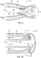
- FIG. 9 is a cross-sectional view of an embodiment of an in situ foam generating eductor 150.
- the eductor 150 includes an outer fluid path 152 configured to receive liquid detergent (e.g., citric based detergent), an inner fluid path 154 configured to receive aerating gas (e.g., air), and an interface 156 between the outer fluid path 152 and the inner fluid path 154.
- the outer fluid path 152 is disposed between the interface 156 and an outer (e.g., annular) wall 155 of the eductor 150.
- the inner fluid path 154 and the outer fluid path 152 are arranged about a longitudinal axis 149 (e.g., the inner fluid path 154 and the outer fluid path 152 are concentric and centered on the longitudinal axis 149).
- the interface 156 in the illustrated embodiment is a wall having openings 158 through which the liquid detergent passes from the outer fluid path 152 to the inner fluid path 154.
- a flow biasing device may cause the liquid to pass through the openings 158.
- the structure of the eductor 150 may enable the Venturi principle, where the flow of the aerating gas through a throat 157 (e.g., Venturi) of the inner path 154 causes a low pressure area proximate the openings 158 of the interface 156 that draws the liquid 152 through the openings 158 of the interface 156.
- the eductor 150 causes the flow of the aerating gas through the throat 157 of the inner path 154 to perform the work of pumping the liquid detergent from the outer path 152 into the inner path 154.
- the liquid detergent and the aerating gas may mix within (and/or downstream of) the throat 157 to generate foam, and the foam may be output at an outlet 153 of the eductor 150.
- An island 159 may be positioned downstream of the throat 157, which may enhance mixing of the detergent and aerating gas.
- FIG. 10 is a cross-sectional view of an embodiment of an in situ foam generating air mixer 160.
- the air mixer 160 includes an outer fluid path 162 configured to receive liquid detergent (e.g., citric based detergent), an inner fluid path 164 configured to receive aerating gas (e.g., air), and an interface 166 between the outer fluid path 162 and the inner fluid path 164.
- the outer fluid path 162 is disposed between the interface 166 and an outer (e.g., annular) wall 165 of the air mixer 160.
- the inner fluid path 164 and the outer fluid path 162 are arranged about a longitudinal axis 149 (e.g., the inner fluid path 164 and the outer fluid path 162 are concentric and centered on the longitudinal axis 149).
- the interface 166 in the illustrated embodiment is a wall having openings 168 through which the air passes from the inner fluid path 164 to a mixing region 167 between the outer fluid path 162 and the outlet 163 (e.g., along the bottleneck between the outer fluid path 162 and the outlet 163).
- the liquid detergent and the aerating gas may mix within the mixing area 167 to generate foam, and the foam may be output at an outlet 163 of the air mixer 160.
- the outlet 163 is disposed at the outer (e.g., annular) wall 165.
- the air mixer 160 may be oriented (during operation/foam generation) such that Earth's gravity vector 169 opposes the flow of the detergent and the aerating gas.
- FIG. 11 is a cross-sectional view of another embodiment of an in situ foam generating air mixer 170.
- the air mixer 170 includes an outer fluid path 172 configured to receive liquid detergent (e.g., citric based detergent), an inner fluid path 174 configured to receive aerating gas (e.g., air), and an interface 176 between the outer fluid path 172 and the inner fluid path 174.
- the outer fluid path 172 is disposed between the interface 176 and an outer (e.g., annular) wall 175 of the air mixer 170.
- the inner fluid path 174 and the outer fluid path 172 are arranged about a longitudinal axis 149 (e.g., the inner fluid path 174 and the outer fluid path 172 are concentric and centered on the longitudinal axis 149).
- the interface 176 in the illustrated embodiment is a wall having openings 178 through which the air passes from the inner fluid path 174 to the outer fluid path 176.
- the liquid detergent and the aerating gas may mix within a mixing area 177 to generate foam, and the foam may be output at an outlet 173 of the air mixer 170.
- Ridges 179 positioned on the outer wall 175 of the device 170, and protruding inward from the outer wall 175, may facilitate control of a pressure drop adjacent the mixing area 177 and/or enhance mixing of the detergent and air.
- the outlet 173 is disposed at an end of the air mixer 170, as opposed to along the outer (e.g., annular) wall 175.
- the air mixer 170 may be oriented (during operation/foam generation) such that Earth's gravity vector 169 does not oppose the flow of the detergent and the aerating gas. In other words, Earth's gravity vector 169 may cause the detergent and the aerating gas to travel toward the outlet 173 in the illustrated air mixer 170, such that liquid detergent does not seep into the inner fluid path 174.
- FIG. 12 is a cross-sectional view of another embodiment of an in situ foam generating air mixer 180.
- the air mixer 180 includes an outer fluid path 182 configured to receive liquid detergent (e.g., citric based detergent), an inner fluid path 184 configured to receive aerating gas (e.g., air), and an interface 186 between the outer fluid path 182 and the inner fluid path 184.
- the outer fluid path 182 is disposed between the interface 186 and an outer (e.g., annular) wall 185 of the air mixer 180.
- the inner fluid path 184 and the outer fluid path 182 are arranged about a longitudinal axis 149 (e.g., the inner fluid path 184 and the outer fluid path 182 are concentric and centered on the longitudinal axis 149).
- the interface 186 in the illustrated embodiment is a wall having openings 188 through which the air passes from the inner fluid path 184 to the outer fluid path 182.
- the liquid detergent and the aerating gas may mix within a mixing area 187 to generate foam, and the foam may be output at one or more outlets 183 of the air mixer 180.
- the outlets 183 are disposed at the outer (e.g., annular) wall 175, as opposed to an end or end cap of the air mixer 180.
- FIG. 13 is a cross-sectional view of embodiment of an in situ foam generating porous air mixer 190 having an inner wicking cap 191.
- the porous air mixer 190 includes an outer fluid path 192 configured to receive liquid detergent (e.g., citric based detergent), an inner fluid path 194 configured to receive aerating gas (e.g., air), and an interface 196 between the outer fluid path 192 and the inner fluid path 194.
- the outer fluid path 192 is disposed between the interface 196 and an outer (e.g., annular) wall 195 of the porous air mixer 190.
- the inner fluid path 194 and the outer fluid path 192 are arranged about a longitudinal axis 149 (e.g., the inner fluid path 194 and the outer fluid path 192 are concentric and centered on the longitudinal axis 149).
- the interface 196 in the illustrated embodiment is an annular wall having the internal wicking cap 191 disposed at an end of the annular wall.
- the internal wicking cap 191 may be soaked with the liquid detergent passing through the outer fluid path 192.
- ridges 199 on an inside of the outer (e.g., annular) wall 195 may protrude radially inward and facilitate control of (e.g., reduce) a pressure drop adjacent the ridges 199, and/or mixing of the detergent and air.
- the aerating gas may pass through the internal wicking cap 191 having the detergent soaked therein.
- foam bubbles may be produced within the wicking cap 191, along a surface 198 of the internal wicking cap 191, and in an area 197 immediately downstream of the internal wicking cap 191.
- the bubbles may be output at the outlet 193 of the porous air mixer 190 illustrated in FIG. 13 .
- FIG. 14 is a cross-sectional view of another embodiment of an in situ foam generating porous air mixer 200 having an end wicking cap 201.
- the porous air mixer 200 includes an outer fluid path 202 configured to receive liquid detergent (e.g., citric based detergent), an inner fluid path 204 configured to receive aerating gas (e.g., air), and an interface 206 between the outer fluid path 202 and the inner fluid path 204.
- the outer fluid path 202 is disposed between the interface 206 and an outer (e.g., annular) wall 205 of the porous air mixer 200.
- the inner fluid path 204 and the outer fluid path 202 are arranged about a longitudinal axis 149 (e.g., the inner fluid path 204 and the outer fluid path 202 are concentric and centered on the longitudinal axis 149).
- the interface 206 in the illustrated embodiment is an annular wall having the end wicking cap 201 disposed at an end of the annular wall.
- the end wicking cap 201 spans between the annular wall of the interface 206 and the outer (e.g., annular) wall 205 radially outward from the outer fluid path 202.
- the end wicking cap 201 may be soaked with the liquid detergent passing through the outer fluid path 202. Further, the aerating gas may pass through the end wicking cap 201 having the detergent soaked therein.
- foam bubbles may be produced within the end wicking cap 201, along a surface 208 of the wicking cap 201, and in an area 207 immediately downstream of the end wicking cap 201 (e.g., within the fluid passageway of the turbine engine).
- the outlet 203 in the illustrated embodiment may be the end wicking cap 201 itself.
- FIG. 15 is a cross-sectional view of another embodiment of an in situ foam generating porous air mixer 210 having a porous wicking insert 211.
- the porous air mixer 210 includes an outer fluid path 212 configured to receive aerating gas (e.g., air), an inner fluid path 214 configured to receive liquid detergent (e.g., citric based detergent), and an interface 216 between the outer fluid path 212 and the inner fluid path 214.
- the outer fluid path 212 is disposed between the interface 216 and an outer (e.g., annular) wall 215 of the porous air mixer 210.
- the inner fluid path 214 and the outer fluid path 212 are arranged about a longitudinal axis 149 (e.g., the inner fluid path 214 and the outer fluid path 212 are concentric and centered on the longitudinal axis 149).
- the interface 216 in the illustrated embodiment is an annular wall having the wicking insert 211 disposed at an end of the annular wall.
- the wicking insert 211 may be soaked with the liquid detergent passing through the inner fluid path 214.
- the wicking insert 211 between the inner surface of the outer (e.g., annular) wall 215 positioned radially outward from the outer fluid path 212.
- the wicking insert 211 also contacts an end of the annular wall portion of the interface 216.
- the aerating gas may pass through the wicking insert 211 having the detergent soaked therein.
- foam bubbles may be produced within the wicking insert 211, along a surface 218 of the wicking insert 211, and in an area 217 immediately downstream of the wicking insert 211.
- the bubbles may be output at the outlet 213 of the porous air mixer 210 illustrated in FIG. 15 .
- FIG. 16 is a cross-sectional view of an embodiment of an in situ foam generating spinner device 220.
- the spinner device 220 includes an outer fluid path 222 configured to receive liquid detergent (e.g., citric based detergent), an inner fluid path 224 configured to receive aerating gas (e.g., air), and an interface 226 between the outer fluid path 222 and the inner fluid path 224.
- the outer fluid path 222 is disposed between the interface 226 and an outer (e.g., annular) wall 225 of the spinner device 220.
- the inner fluid path 224 and the outer fluid path 222 are arranged about a longitudinal axis 149 (e.g., the inner fluid path 224 and the outer fluid path 222 are concentric and centered on the longitudinal axis 149).
- the interface 226 in the illustrated embodiment includes a wall and a spinner 221 (e.g., fan, blower, fan wheel, blades, etc.).
- the spinner 221 may turn to draw the aerating gas toward the spinner 221, and to mix the aerating gas with the detergent flowing through the outer fluid path 222 toward the spinner 221.
- foam bubbles may be generated at the spinner 221 and in an area 227 immediately downstream from the spinner 221.
- the bubbles may be output at the outlet 223 of the spinner device 220 in the illustrated embodiment.
- FIG. 17 is an embodiment of a block diagram 300 of cleaning a turbine engine.
- the block diagram 300 includes inserting (block 301) an in situ foam generating device of a foam generating assembly of a cleaning system into an interior a turbine engine.
- the in situ foam generating device may be inserted through a port of the turbine engine (e.g., a borescope inspection port, an ignitor port, a fuel nozzle orifice, or another port), a throat of the turbine engine, or between blades and a stator of the turbine engine.
- the in situ foam generating device (or another portion or component of the foam generating assembly) may include a coupling mechanism that interfaces with (e.g., clamps onto) a feature of the turbine engine, such as a wall of the turbine engine surrounding the port through which the in situ foam generating device is disposed, to maintain a position of the in situ foam generating device within the interior of turbine engine.
- a coupling mechanism that interfaces with (e.g., clamps onto) a feature of the turbine engine, such as a wall of the turbine engine surrounding the port through which the in situ foam generating device is disposed, to maintain a position of the in situ foam generating device within the interior of turbine engine.
- the block diagram also includes generating (block 302) foam, via the in situ foam generating device, from a detergent and an aerating gas in the interior (e.g., fluid passageway) of the turbine engine.
- the detergent and the aerating gas may be individually and/or separately routed to an in situ foam generating device positioned within the turbine engine.
- the in situ foam generating device may receive the aerating gas and the detergent, and may mix the aerating gas and the detergent to form the foam.
- the foam may be output from the in situ foam generating device to an internal area of the turbine engine.
- the block diagram 300 also includes soaking (block 304) a fluid passageway of the turbine engine with the foam.
- the foam may contact surfaces of the turbine engine and may soak the surfaces of the turbine engine for a period of time.
- the turbine engine may be turned as the foam travels through the turbine engine, which may cause the foam to contact a greater number or percentage of surfaces of the turbine engine.
- the block diagram 300 may also include rinsing or flushing (block 306) the fluid passageway of the turbine engine after the above-described soaking procedure.
- the foam may loosen, break down, or otherwise remove contaminants disposed on the surfaces of the turbine engine.
- the foam may collapse into an effluent having the detergent, the contaminants, and other materials (e.g., surfactants) that may be mixed with, or a part of, the detergent.
- the effluent may then be rinsed or flushed from the fluid passageway.
- the block diagram 300 may include the use of several in situ foam generating devices configured to generate foam at various locations internal to the turbine engine.
- the in situ foam generating devices may be inserted through various ports and orifices of the turbine engine.
- Each in situ foam generating device may include independent aerating gas and detergent sources, or the in situ foam generating devices may receive aerating gas form the same aerating gas source, and detergent from the same detergent source.
- the in situ foam generating devices may be used exclusively, or together with other foam generating assemblies or devices that clean certain portions of the turbine engine.
- in situ foam generation reduces a traversal distance of the generated foam between the generating device and the target cleaning surface in the interior of the turbine engine. By reducing the traversal distance, bubble diameters and bubble collapse are more controllable. Further, for the above reasons, more cost effective materials (e.g., having a lower foam stability) may be used to achieve the same or better cleaning results (e.g., accuracy, efficiency) compared to traditional embodiments having external foam generation.
Landscapes
- Engineering & Computer Science (AREA)
- Chemical & Material Sciences (AREA)
- Chemical Kinetics & Catalysis (AREA)
- Mechanical Engineering (AREA)
- General Engineering & Computer Science (AREA)
- Combustion & Propulsion (AREA)
- Cleaning By Liquid Or Steam (AREA)
- Other Liquid Machine Or Engine Such As Wave Power Use (AREA)
Abstract
Description
- The invention disclosed herein relates to cleaning of turbine engines. More specifically, the present disclosure relates to generation of cleaning foam.
- Turbine engines (e.g., gas turbine engines, such as aircraft engines) typically combust a mixture of carbonaceous fuel and compressed oxidant to generate high temperature, high pressure combustion gases. The combustion gases drive a turbine, which may be coupled via a shaft to a compressor. In some embodiments, the shaft may also be coupled to an electrical generator. In such embodiments, as the combustion gases drive the turbine and corresponding shaft into rotation, the shaft outputs power to the electrical generator. In aircraft engines, the combustion gases may pass through the turbine and through a nozzle, causing the exhaust gas exiting the nozzle to produce thrust.
- Unfortunately, turbine engines are generally susceptible to deposits or contaminants, such as dust in particular, which may reduce efficiency and/or effectiveness of the turbine engine. Generally, the deposits and contaminants may be formed or may gather in any component of the turbine engine, including but not limited to the compressor, the combustor or combustion chamber, and the turbine. Unfortunately, traditional cleaning systems utilizing cleaning foam may be imprecise and inefficient. Accordingly, improved cleaning systems are needed for gas turbine engines.
- In one embodiment, a turbine system includes a foam generating assembly having an in situ foam generating device at least partially positioned within the fluid passageway of the turbine engine, such that the in situ foam generating device is configured to generate foam within the fluid passageway of the turbine engine.
- In another embodiment, an in situ foam generating device of a cleaning system for a turbine engine includes an inner fluid path and an outer fluid path concentric with the inner fluid path, wherein the inner fluid path is configured to receive one of a foaming liquid or an aerating gas, and wherein the outer fluid path is configured to receive the other of the foaming liquid or the aerating gas. The in situ foam generating device also includes an interface between the inner fluid path and the outer fluid path, where the interface enables mixing of the aerating gas with the foaming liquid to generate foam.
- These and other features, aspects, and advantages of the present invention will become better understood when the following detailed description is read with reference to the accompanying drawings in which like characters represent like parts throughout the drawings, wherein:
-
FIG. 1 is a cross-sectional schematic view of an embodiment of a turbine system having a turbine engine, a foam generating assembly, and an in situ foam generating device of the foam generating assembly, in accordance with an aspect of the present disclosure; -
FIG. 2 is a cross-sectional schematic view of an embodiment of an aircraft turbine engine having a foam generating assembly with an in situ foam generating device for cleaning the aircraft turbine engine, in accordance with an aspect of the present disclosure; -
FIG. 3 is a cross-sectional schematic view of an embodiment of a cleaning volume or fluid passageway of the aircraft turbine engine ofFIG. 2 , in accordance with an aspect of the present disclosure; -
FIG. 4 is a plot illustrating certain technical effects associated with the in situ foam generating device ofFIGS. 1 and2 , in accordance with an aspect of the present disclosure; -
FIG. 5 is another plot illustrating certain technical effects associated with the in situ foam generating device ofFIGS. 1 and2 , in accordance with an aspect of the present disclosure; -
FIG. 6 is another plot illustrating certain technical effects associated with the in situ foam generating device ofFIGS. 1 and2 , in accordance with an aspect of the present disclosure; -
FIG. 7 is a schematic illustration of a portion of the turbine system ofFIG. 1 prior to insertion of the in situ foam generating device into the turbine engine, in accordance with an aspect of the present disclosure; -
FIG. 8 is a schematic illustration of a portion of the turbine system ofFIG. 1 after insertion of the in situ foam generating device within the turbine engine, in accordance with an aspect of the present disclosure; -
FIG. 9 is a cross-sectional view of an embodiment of an in situ foam generating device for use in a foam generating assembly of a turbine engine cleaning system, in accordance with an aspect of the present disclosure; -
FIG. 10 is a cross-sectional view of another embodiment of an in situ foam generating device for use in a foam generating assembly of a turbine engine cleaning system, in accordance with an aspect of the present disclosure; -
FIG. 11 is a cross-sectional view of another embodiment of an in situ foam generating device for use in a foam generating assembly of a turbine engine cleaning system, in accordance with an aspect of the present disclosure; -
FIG. 12 is a cross-sectional view of another embodiment of an in situ foam generating device for use in a foam generating assembly of a turbine engine cleaning system, in accordance with an aspect of the present disclosure; -
FIG. 13 is a cross-sectional view of another embodiment of an in situ foam generating device for use in a foam generating assembly of a turbine engine cleaning system, in accordance with an aspect of the present disclosure; -
FIG. 14 is a cross-sectional view of another embodiment of an in situ foam generating device for use in a foam generating assembly of a turbine engine cleaning system, in accordance with an aspect of the present disclosure; -
FIG. 15 is a cross-sectional view of another embodiment of an in situ foam generating device for use in a foam generating assembly of a turbine engine cleaning system, in accordance with an aspect of the present disclosure; -
FIG. 16 is a cross-sectional view of another embodiment of an in situ foam generating device for use in a foam generating assembly of a turbine engine cleaning system, in accordance with an aspect of the present disclosure; and -
FIG. 17 is an embodiment of a block diagram of cleaning a turbine engine with a cleaning system having a foam generating assembly that includes an in situ foam generating device, in accordance with an aspect of the present disclosure. - Turbine engines (e.g., gas turbine engines, such as certain aircraft engines) typically combust a mixture of carbonaceous fuel and compressed oxidant to generate high temperature, high pressure combustion gases, which are utilized in a number of ways depending on the type of turbine engine. For example, the combustion products may cause components of the turbine engine to output power to an electrical generator. Additionally or alternatively, the combustion products may pass through a nozzle (e.g., in an aero-derivative turbine engine) to produce thrust.
- Unfortunately, gas turbine engines are generally susceptible to deposits or contaminants, such as dust in particular, which may reduce efficiency and/or effectiveness of the turbine engine. Generally, the deposits and contaminants may be formed or may gather in any component of the turbine engine, including but not limited to the compressor, the combustor or combustion chamber, and the turbine.
- In accordance with present embodiments, a cleaning system for cleaning the turbine engines such as those described above includes a foam generating assembly at least partially positioned internal to the turbine engine. For example, the foam generating assembly includes an in situ foam generating device having a foam outlet that, when the in situ foam generating device is installed during a cleaning procedure, opens into a fluid passage of the turbine engine. "In situ foam generating device" used in this present specification is intended to mean that the foam generating device and the target cleaning area are both disposed internal to the turbine engine, such that the foam is generated within the turbine engine and delivered to the target within the turbine engine. In other words, materials to generate the foam are conveyed (e.g., via hoses) into the foam generating device positioned within the turbine engine, which receives the materials and generates the foam inside the turbine engine. In particular, the in situ foam generating device may be positioned within a fluid passageway (e.g., a hot gas path, a cooling circuit, or both) of the turbine engine, such that the foam is generated within the fluid passageway and delivered through the fluid passageways to one or more cleaning targets.
- As noted above, materials for generating the foam may be individually conveyed to the in situ foam generating device. For example, the in situ foam generating device may receive a detergent (e.g., a liquid detergent, such as a water-based detergent containing citric acid) or other foaming liquid and an aerating gas (e.g., air, nitrogen), and may mix the detergent and the aerating gas to generate bubbles. The bubbles may be directed from an outlet of the foam generating device toward general and/or targeted areas of the turbine engine for cleaning the turbine engine. The in situ foam generating device may be coupled with a detergent storage source or tank (e.g., via a detergent hose), and an intervening flow biasing device (e.g., a pump) may be controlled to supply the detergent from the detergent storage tank, through the hose, and to the in situ foam generating device. Likewise, the in situ foam generating device may be coupled to an aerating gas source or tank (e.g., via an aerating gas hose), and an intervening flow biasing device (e.g., a fan or blower) may be controlled to supply the aerating gas from the detergent storage tank, through the hose, and to the in situ foam generating device. In some embodiments, the detergent hose and the aerating gas hose may be concentric with each other proximate the in situ foam generating device. In other words, in some embodiments, the aerating gas hose may be encapsulated by the detergent hose, or vice versa, adjacent the in situ foam generating device.
- As described above, the in situ foam generating device may generate foam in an area internal to the turbine engine (e.g., within a fluid passageway of the turbine engine). In doing so, foam quality may be improved compared to embodiments in which foam is generated external to the turbine engine and subsequently routed to the turbine engine. For example, bubbles generated via traditional external generators must be routed into the turbine engine, which may cause undesired expansion of the foam bubbles. The undesired expansion of the foam bubbles may cause at least certain of the bubbles to be too large to pass through certain openings, orifices, or regions of the fluid passageway of the turbine engine. Additionally, as the foam bubbles are routed between the traditional external foam generator and the turbine engine and grow in size, a large percentage of the foam bubbles may collapse prior to contacting, soaking, or otherwise adequately cleaning the inside of the turbine engine, thereby reducing an efficiency of the cleaning procedure. The in situ foam generating device of the present disclosure facilitates improved bubble diameter and improved bubble collapse percentages, thereby improving a cleaning precision and efficiency of the cleaning system. In other words, since the in situ foam generating device facilitates more precise bubble qualities and does not require a large traversal distance to the turbine engine, the bubbles are more effective and require less resources (e.g., detergent, water, and aerating gas) than traditional embodiments.
- Further to the points above, the in situ foam generating device maybe configured (e.g., sized) such that it is capable of being positioned through various ports of the turbine engine (e.g., borescope inspection ports, igniter ports, fuel nozzle orifices), a throat area of the turbine engine (e.g., if properly sized), and/or between rotor blades and a stator of the turbine engine. Accordingly, the in situ foam generating device supplies improved bubbles closer to targeted areas that would otherwise be difficult to clean in traditional embodiments. In other words, the in situ foam generating device facilitates improved bubble quality for general cleaning, in addition to improved access to targeted areas of the turbine engine that are traditionally difficult to reach.
- Further still, in part because of the advantages described above, more cost effective materials having lower foam stability may be used to generate the foam in disclosed internal foam generation embodiments. For example, since the bubbles in the disclosed internal foam generation embodiments are closer to the areas of the turbine engine requiring cleaning, the bubbles may not need to maintain bubble integrity for as long as a volume of bubbles that requires passage to the turbine engine from an external foam generator. In other words, because the foam bubbles in disclosed embodiments are closer to the turbine cleaning areas than those in externally generated embodiments, a higher collapse rate may be desired as a means to reduce material cost and reduce a cleaning time period. Indeed, using materials with lower foam stability may enable the improved material cost and may enable the shorter cleaning time. These and other features will be described in detail below with reference to the drawings.
- Turning now to the drawings,
FIG. 1 is a block diagram of aturbine system 10 and acleaning system 11 configured to clean theturbine system 10. Theturbine system 10 includes afuel injector 12, afuel supply 14, acombustor 16, and aturbine 18. As illustrated, thefuel supply 14 routes a liquid fuel and/or gas fuel, such as natural gas, to thegas turbine system 10 through thefuel injector 12 and into thecombustor 16. As discussed below, thefuel injector 12 is configured to inject and mix the fuel with compressed air. Thecombustor 16 ignites and combusts the fuel-air mixture, and then passes hot pressurized exhaust gas into theturbine 18. As will be appreciated, theturbine 18 includes one or more stators having fixed vanes or blades, and one or more rotors having blades which rotate relative to the stators. The exhaust gas passes through the turbine rotor blades, thereby driving the turbine rotor to rotate. Coupling between the turbine rotor and ashaft 19 will cause the rotation of theshaft 19, which is also coupled to several components throughout thegas turbine system 10, as illustrated. Eventually, the exhaust of the combustion process may exit thegas turbine system 10 via anexhaust outlet 20. In some embodiments, thegas turbine system 10 may be a gas turbine system of an aircraft, in which theexhaust outlet 20 may be a nozzle through which the exhaust gases are accelerated. Acceleration of the exhaust gases through the exhaust outlet 20 (e.g., the nozzle) may provide thrust to the aircraft. As described below, the shaft 19 (e.g., in an aircraft gas turbine system 10) may be coupled to a propeller, which may provide thrust to the aircraft in addition to, or in place of, the exhaust gases accelerated through the exhaust outlet 20 (e.g., the nozzle). - A
compressor 22 includes blades rigidly mounted to a rotor which is driven to rotate by theshaft 19. As air passes through the rotating blades, air pressure increases, thereby providing thecombustor 16 with sufficient air for proper combustion. Thecompressor 22 may intake air to thegas turbine system 10 via anair intake 24. Further, theshaft 19 may be coupled to aload 26, which may be powered via rotation of theshaft 19. As will be appreciated, theload 26 may be any suitable device that may use the power of the rotational output of thegas turbine system 10, such as a power generation plant or an external mechanical load. For example, theload 26 may include an electrical generator, a propeller of an airplane as previously described, and so forth. Theair intake 24 drawsair 30 into thegas turbine system 10 via a suitable mechanism, such as a cold air intake. Theair 30 then flows through blades of thecompressor 22, which provides compressedair 32 to thecombustor 16. In particular, thefuel injector 12 may inject thecompressed air 32 andfuel 14, as a fuel-air mixture 34, into thecombustor 16. Alternatively, thecompressed air 32 andfuel 14 may be injected directly into the combustor for mixing and combustion. - The
turbine system 10 may be susceptible to gathering of deposits or contaminants, namely dust, within components of theturbine system 10. Accordingly, as illustrated, theturbine system 10 includes thecleaning system 11 fluidly coupled to at least one component of theturbine system 10. For example, the illustratedcleaning system 11 includes afoam generating assembly 13 having an in situfoam generating device 15. The in situfoam generating device 15 is illustrated as positioned within theturbine 18, although the in situfoam generating device 15 may be positioned internal to a different component of theturbine system 10, such as the air intake(s) 24, thecompressor 22, the fuel injector(s) 12, the combustor(s) 16, theturbine 18, and/or theexhaust outlet 20. The in situfoam generating device 15 is configured to receive a foaming liquid or, more specifically, a detergent (e.g., liquid citric acid based detergent) from a detergent source orstorage tank 17, and aerating gas (e.g., air, nitrogen) from an aerating gas source orstorage tank 21. In some embodiments, a surfactant may be mixed with the detergent at thedetergent storage tank 17, or at any location downstream of thedetergent storage tank 17. The in situfoam generating device 15 may mix the detergent and the aerating gas to form bubbles inside afluid passageway 35 of the turbine 18 (and/or other components of the turbine system 10). Thefluid passageway 35 may include a hot gas path of theturbine system 10, a cooling circuit of theturbine system 10, or both. In general, the in situfoam generating device 15 may be configured (e.g., sized, shaped) to be disposed internal to the turbine 18 (and/or other components of the turbine system 10) by passing the in situfoam generating device 15 through a port of theturbine system 10. As described above and in detail below with reference to the drawings, the in situfoam generating device 15 enables an improved foam quality compared to traditional embodiments, enhancing an efficiency of the cleaning procedure in terms of both cost and time. Although the components of theturbine system 10 inFIG. 1 are illustrated as separate blocks, the components (or certain components) may connected such that thefluid passageway 35 extends continuously through multiple ones of the components of the turbine system 10 (e.g., theturbine 18, thecombustor 16, thefuel injectors 12, thecompressor 22, theair intake 24, or a combination thereof). - The
cleaning system 11 inFIG. 1 is configured to generate, and provide to the component(s) of thegas turbine system 10, a foam output from the in situfoam generating device 15 into thefluid passageway 35 of theturbine system 10. The foam loosens, soaks, absorbs, and/or cleans the deposits or contaminants, namely dust, within the components of theturbine system 10. Thecleaning system 11 may also include components configured to rinse thegas turbine system 10 after the detergent based foam soaks the insides of the components of thegas turbine system 10 for a defined period of time. For example, a flushingassembly 23 may rinse or flush the effluent (e.g., collapsed foam and contaminants) from the turbine system 10 (e.g., with jets of water). Although the flushingassembly 23 is illustrated as interfacing with theturbine system 10 at a similar location as the in situfoam generating device 15 of thefoam generating assembly 13, the flushingassembly 23 may access theturbine system 10 at a different location. -
FIG. 2 illustrates a cross-sectional schematic view of an embodiment of thecleaning system 11 and an aircraft gas turbine engine 40 (e.g., aero-derivative gas turbine engine) that includes afan assembly 41 and acore engine 42 including ahigh pressure compressor 43, acombustor 44, a high-pressure turbine (HPT) 45, and a low-pressure turbine (LPT) 46. In general, thecleaning system 11 may be equipped with the in situfoam generating device 15 positioned within thefluid passageway 35 of the aircraftgas turbine engine 40, as previously described. The illustrated aircraftgas turbine engine 40 may be an example of thegas turbine system 10 illustrated inFIG. 1 . In the illustrated embodiment, thefan assembly 41 of the gas turbine engine 40 (e.g., aircraft gas turbine engine) includes an array offan blades 47 that extend radially outward from arotor disk 48. Thegas turbine engine 40 has an intake side (e.g., proximate the fan assembly 41) and an exhaust side (e.g., proximate the LPT 46). Thefan assembly 41 and the LPT 46 are coupled by a low-speed rotor shaft 49, and thehigh pressure compressor 43 and theHPT 45 are coupled by ahighspeed rotor shaft 51. Thegas turbine engine 40 may be any type of gas or combustion turbine aircraft engine including, but not limited to, turbofan, turbojet, turboprop, turboshaft engines as well as geared turbine engines such as geared turbofans, un-ducted fans and open rotor configurations. Alternatively, thegas turbine engine 40 may be any time of gas or combustion turbine engine, including, but not limited to, land-based gas turbine engines in simply cycle, combined cycle, cogeneration, marine and industrial applications. - Generally, in operation, air flows axially through the
fan assembly 41, in a direction that is substantially parallel to acenterline 53 that extends through thegas turbine engine 40, and compressed air is supplied to thehigh pressure compressor 43. The highly compressed air is delivered to thecombustor 44. Combustion gas flow (not shown) from thecombustor 44 drives theturbines 45 and 46. TheHPT 45 drives thecompressor 43 by way of theshaft 51, and the LPT 46 drives thefan assembly 41 by way of theshaft 49. Moreover, in operation, foreign material, such as mineral dust, is ingested by thegas turbine engine 40 along with the air, and the foreign material accumulates on surfaces therein. - As shown, the
cleaning system 11 includes afoam generating assembly 13 having the in situfoam generating device 15, the detergent storage tank 17 (or source), the aerating gas storage tank 21 (or source), and ahose assembly 50 for routing the detergent and the aerating gas from thestorage tanks foam generating device 15. Thehose assembly 50 in the illustrated embodiment includes, downstream from ahose juncture 54, a dual-hose portion 55 in which the hose assembly includes an inner hose that receives either the aerating gas or the detergent, and an outer hose encapsulating the inner house and configured to receive, between an inner wall of the outer house and an outer wall of the inner hose, the other of the detergent or the aerating gas. However, other arrangements of thehose assembly 50 are also possible and will be described with reference to later figures. The in situfoam generating device 15 is configured to receive the aerating gas and the detergent while the in situfoam generating device 15 is positioned within the aircraftgas turbine engine 40, generate the foam, and supply the foam to thefluid passageway 35. The flushingassembly 23 of thecleaning system 11 may be configured to rinse the effluent from the fluid passageway after a soaking period lapses. For clarity, another example of an embodiment of thefluid passageway 35 extending continuously through various components of thegas turbine engine 40 ofFIG. 2 (e.g., through at least thecompressor 43, thecombustor 44, and the turbine stages 45, 46) is shown inFIG. 3 . InFIG. 3 , thefluid passageway 35 may include ahot gas path 37 and acooling circuit 39, where thehot gas path 37 is depicted schematically inFIG. 3 as a center of thefluid passageway 35, and thecooling circuit 39 is depicted schematically inFIG. 3 as surrounding the hot gas path 37 (e.g., along an edge of the hot gas path 37). It should be noted that thecooling circuit 39 may be substantially fluidly isolated from thehot gas path 37. Further, the disclosed in situfoam generating device 15 may access thehot gas path 37 and thecooling circuit 39 independently or simultaneously. - While
FIGS. 7-16 illustrate various aspects of thefoam generating assembly 13 having the in situfoam generating device 15,FIGS. 4-6 are first provided and described to depict certain advantages associated with in situ foam generation. For example,FIG. 4 includes aplot 60 illustratingbubble diameter 62 as a function ofbubble traversal distance 64. In traditional embodiments, foam is generated external to a turbine engine, routed to the turbine engine, and then routed to a particular location or target 65 within the turbine engine (e.g., as illustrated by the external foam generation bubble size data 66). Using in situ foam generation in accordance with the present disclosure, the foam is generated inside the turbine engine, in some cases immediately adjacent the target 65 (e.g., as illustrated by the internal foam generation bubble size data 68). During foam traversal, the bubbles forming the foam may expand. Since traditional embodiments require a larger traversal distance than the in situ embodiments described by the present disclosure, the bubbles may include larger bubble diameters once the bubbles reach thetarget 65. Bubbles having too large of a diameter may have difficulty passing through smaller areas, openings, orifices, or fluid paths inside the turbine, which may reduce an effectiveness of the cleaning procedure. Accordingly, the smaller and more controllable bubble sizes associated with internal foam generation may be desired for improved efficiency and effectiveness of the cleaning procedure. In general, bubble diameters between 25 microns and 1 millimeter are desirable. Further, by utilizing the in situ foam generation, the bubbles may expand in size along the traversal distance between the in situ foam generation device and the target cleaning area by no more than 500%. In some embodiments in accordance with the present disclosure, the bubbles may increase in size along the traversal distance no more than 400%, no more than 300%, or no more than 200%, depending on a proximity of the generating device and the target cleaning area (i.e., the traversal distance). - It should be noted that, while not included in the
plots FIGS. 4-6 , foam temperature is another factor dependent on traversal distance. For example, as the foam travels from the generating device toward the target cleaning position or region, a temperature of the foam may decrease as energy is lost. By generating the foam internal to the turbine engine, the loss of energy or temperature may be reduced, thereby reducing or negating cleaning cycles that produce foam having insufficient temperature. Since the traversal distance of internally generated foam is less than that of externally generated foam, the temperature of the internally generated foam may be more controllable and less reliant on features involved during foam traversal (e.g., ambient temperature, imperfections along the traversal distance, etc.). Additionally or alternatively, in some embodiments, the initial starting temperature of the internally generated foam may be less than the initial starting temperature of traditional externally generated foam, which may reduce a cleaning cost. In accordance with certain embodiments, the foam may be generated with an initial temperature of approximately 85-125 degrees Celsius, and may be delivered to the target cleaning region at a temperature of approximately 70-105 degrees Celsius. In general, the temperature of the foam in accordance with present embodiments may drop by 20% or less along the traversal distance from the in situ foam generating device and the target cleaning area, region, or point. - It should also be noted that
FIG. 4 assumes a comparable initial bubble size between the externally generated foam and the internally generated foam. Although it appears as though the externally generated foam could be generated with a smaller initial bubble diameter than that of the internally generated foam such that the externally and internally generated foam embodiments include comparable bubble size at thetarget 65, bubbles having different initial bubble diameters behave differently. For example, bubbles having smaller initial diameters may coarsen at a higher rate (e.g., as an inverse function of the bubble diameter or radius) than those having larger initial diameters, which may cause a poor bubble size distribution, may cause expansion and/or collapsing of the bubbles, and in general may reduce an effectiveness of the foam. Further, a minimum bubble diameter for foam generated to clean turbine engines is approximately 0.10 millimeters or 0.05 millimeters, depending on features such as materials/devices used. In other words, bubble diameter is more controllable (and/or evenly distributed) for delivery to thetarget 65 with internal foam generation than with external foam generation, even if the bubbles in external foam generation include smaller initial diameters. -
FIG. 5 includes aplot 70 illustratingbubble collapse percentage 72 as a function of thefoam traversal distance 64. Similar to theplot 60 illustratingbubble diameter 62 as a function of thefoam traversal distance 64, theplot 70 illustrates advantages of internal foam generation compared to external foam generation. For example, as the foam travels between the foam generating device and thetarget 65, the bubbles forming the foam may expand until they collapse. Of course, certain bubbles will expand and collapse at different rates; thus, the volume of foam may include a percentage of collapsed foam that increases as a function oftraversal distance 64. Since embodiments having external foam generation require a greater traversal distance (i.e., represented by the external foam generationcollapse percentage data 76 in the illustrated plot 70), a larger percentage of the bubbles forming the foam collapses by the time the volume of foam reaches thetarget 65 than embodiments having internal foam generation (i.e., represented by the internal foam generationcollapse percentage data 78 in the illustrated plot 70). Reducing a percentage of bubbles that collapse before reaching thetarget 65 may improve effectiveness of the cleaning procedure. - The
plot 70 included inFIG. 5 assumes that the same detergent and aerating gas is used for the external foam generation and the internal foam generation. The illustratedplot 70 illustrates how, assuming the same materials, the internal foam generation can enable a reduced amount of collapsed bubbles at thetarget 65. - Additionally or alternatively, internal foam generation may enable the use of cheaper, less stable materials to generate the foam. For example,
FIG. 6 includes anotherplot 80 illustrating thebubble collapse percentage 72 as a function of thefoam traversal distance 64. Similar to theplots plot 80 illustrates advantages of internal foam generation compared to external foam generation. For example, cheaper and less stable materials may be selected for the external foam generating embodiments such that a rate of bubble collapse is increased compared to internal foam generating embodiments utilizing more stable materials. Indeed, whileFIGS. 5 and 6 both plotbubble collapse percentage 72 as a function oftraversal distance 64, the internally generatedfoam data 79 inFIG. 6 includes a different (i.e., greater) slope than any of theother foam data FIGS. 5 and 6 , since the internally generatedfoam data 79 inFIG. 6 is indicative of a foam formed by less stable, more cost-effective materials than that of theother foam data FIG. 6 illustrates how the reducedtraversal distance 64 associated with in situ foam generation, coupled with the use of less stable materials, may result in the internally generated bubbles of theinternal foam data 79 ofFIG. 6 having thesame collapse percentage 72 at thetarget 65 as externally generated bubbles utilizing more stable materials. In addition to material cost savings, the bubbles associated with the internalbubble generation data 79 ofFIG. 6 and formed by less stable materials will collapse faster after reaching the target 65 (e.g., during a soaking period), which reduces an amount of time required to clean the turbine engine. By reducing a time required for the cleaning period, a turbine engine maintenance period is reduced. The less stable materials may include a more cost effective detergent, a more cost effective aerating gas, a more cost effective ratio of detergent to aerating gas, a more cost effective surfactant, or a combination thereof. As suggested in the illustrations, the more cost-effective, less stable materials in the internally generatedfoam data 79 ofFIG. 6 could not be used with an external foam generator, since the collapse percentage would be far too high. -
FIGS. 7 and 8 are schematic illustrations of thefoam generating assembly 13 having the in situfoam generating device 15 being inserted through aport 100 of a component of aturbine engine 101. As previously described, theport 100 may be an existing port (e.g., a borescope inspection port, an ignitor port, a fuel nozzle orifice, or some other opening in the turbine engine 101). The in situfoam generating device 15 may be sized to fit through theport 100. For example, as illustrated inFIG. 7 , a maximum diameter orwidth 104 of the in situ foamingdevice 15 is less than a minimum diameter orwidth 102 of theport 100. The minimum diameter orwidth 102 of theport 100 may be one inch (approximately 25 millimeters), one half inch (approximately 13 millimeters), or one quarter inch (approximately 6 millimeters), depending on the embodiment and/orport 100. Thus, the maximum diameter orwidth 104 of the in situ foaming device 15 (or the portion thereof passing through the port 100) may be less than one inch, one half inch, or one quarter inch. Accordingly, as illustrated inFIG. 8 , the in situ foamingdevice 15 is capable of passing through theport 100 for positioning inside the component of theturbine engine 101. - As previously described, a
hose arrangement 50 may couple the in situ foamingdevice 15 with the detergent storage tank 17 (or source) and the aerating gas detergent storage tank 21 (or source). Thehose arrangement 50 may include two separate, side-by-side hoses as shown, or thehose arrangement 50 may include at least a portion having an outer hose encapsulating an inner hose, where the outer hose routes one of the detergent or aerating gas, and the inner hose routes the other of the detergent or aerating gas (e.g., as illustrated in, and described with respect to,FIG. 2 ). As will be appreciated in view of later figures, the in situ foamingdevice 15 may include inner and outer fluid paths that couple with the aforementioned inner and outer hoses. However, the side-by-side hose arrangement 50 illustrated inFIGS. 7 and 8 may also be capable of interfacing with inner and outer fluid paths of the in situ foaming device 15 (e.g., via a manifold or juncture configuration positioned at or within the in situ foaming device 15). Other aspects of the in situ foamingdevice 15 will be described in detail below with reference toFIGS. 9-16 . - Since the detergent may be a liquid based citric acid detergent, a flow biasing device such as a
pump 108 may be used to route the detergent from thetank 17 to the in situfoam generating device 15. As previously described, the detergent may also include a surfactant mixed therein (e.g., at thetank 17 or elsewhere). A flow biasing device such as afan 110 or blower may be used to route the aerating gas from thetank 21 to the in situfoam generating device 15. The foam generating assembly 13 (e.g., of the cleaning system) may include the in situfoam generating device 15, the hoses of thehose arrangement 50, thepump 108 and thetank 17, thefan 110 and thetank 21, or a combination thereof. -
FIGS. 9-16 illustrate various embodiments of the in situ foam generating device. It should be noted that, while certain ofFIGS. 9-16 illustrate in situ foam generating devices having axisymmetric and/or cylindrically arranged flow paths and features, any of the illustrated embodiments may include non-axisymmetric and/or non-cylindrical arrangements. Indeed, the devices may be rectangular, triangular, cylindrical, hexagonal, octagonal, irregular, or otherwise shaped. Further, the features (e.g., inner and outer fluid paths, or other features) of the device may be centered on a longitudinal axis, or one or more of the features (e.g., the inner fluid path, the outer fluidpath, or both, or other features) may be offset from, or not centered on, the longitudinal axis. Certain ofFIGS. 9-16 are illustrated and/or described as axisymmetric and/or cylindrical for purposes of clarity, but any ofFIGS. 9-16 may include non-axisymmetric and/or non-cylindrical arrangements. - For example,
FIG. 9 is a cross-sectional view of an embodiment of an in situfoam generating eductor 150. In the illustrated embodiment, theeductor 150 includes an outerfluid path 152 configured to receive liquid detergent (e.g., citric based detergent), an innerfluid path 154 configured to receive aerating gas (e.g., air), and aninterface 156 between the outerfluid path 152 and the innerfluid path 154. The outerfluid path 152 is disposed between theinterface 156 and an outer (e.g., annular)wall 155 of theeductor 150. The innerfluid path 154 and the outerfluid path 152 are arranged about a longitudinal axis 149 (e.g., the innerfluid path 154 and the outerfluid path 152 are concentric and centered on the longitudinal axis 149). Theinterface 156 in the illustrated embodiment is awall having openings 158 through which the liquid detergent passes from the outerfluid path 152 to the innerfluid path 154. In some embodiments, a flow biasing device may cause the liquid to pass through theopenings 158. Additionally or alternatively, the structure of theeductor 150 may enable the Venturi principle, where the flow of the aerating gas through a throat 157 (e.g., Venturi) of theinner path 154 causes a low pressure area proximate theopenings 158 of theinterface 156 that draws the liquid 152 through theopenings 158 of theinterface 156. In other words, theeductor 150 causes the flow of the aerating gas through thethroat 157 of theinner path 154 to perform the work of pumping the liquid detergent from theouter path 152 into theinner path 154. The liquid detergent and the aerating gas may mix within (and/or downstream of) thethroat 157 to generate foam, and the foam may be output at anoutlet 153 of theeductor 150. Anisland 159 may be positioned downstream of thethroat 157, which may enhance mixing of the detergent and aerating gas. -
FIG. 10 is a cross-sectional view of an embodiment of an in situ foam generatingair mixer 160. In the illustrated embodiment, theair mixer 160 includes an outerfluid path 162 configured to receive liquid detergent (e.g., citric based detergent), an innerfluid path 164 configured to receive aerating gas (e.g., air), and aninterface 166 between the outerfluid path 162 and the innerfluid path 164. The outerfluid path 162 is disposed between theinterface 166 and an outer (e.g., annular)wall 165 of theair mixer 160. The innerfluid path 164 and the outerfluid path 162 are arranged about a longitudinal axis 149 (e.g., the innerfluid path 164 and the outerfluid path 162 are concentric and centered on the longitudinal axis 149). Theinterface 166 in the illustrated embodiment is awall having openings 168 through which the air passes from the innerfluid path 164 to amixing region 167 between the outerfluid path 162 and the outlet 163 (e.g., along the bottleneck between the outerfluid path 162 and the outlet 163). The liquid detergent and the aerating gas may mix within the mixingarea 167 to generate foam, and the foam may be output at anoutlet 163 of theair mixer 160. In the illustrated embodiment, theoutlet 163 is disposed at the outer (e.g., annular)wall 165. In some embodiments, theair mixer 160 may be oriented (during operation/foam generation) such that Earth'sgravity vector 169 opposes the flow of the detergent and the aerating gas. -
FIG. 11 is a cross-sectional view of another embodiment of an in situ foam generatingair mixer 170. In the illustrated embodiment, theair mixer 170 includes an outerfluid path 172 configured to receive liquid detergent (e.g., citric based detergent), an innerfluid path 174 configured to receive aerating gas (e.g., air), and aninterface 176 between the outerfluid path 172 and the innerfluid path 174. The outerfluid path 172 is disposed between theinterface 176 and an outer (e.g., annular)wall 175 of theair mixer 170. The innerfluid path 174 and the outerfluid path 172 are arranged about a longitudinal axis 149 (e.g., the innerfluid path 174 and the outerfluid path 172 are concentric and centered on the longitudinal axis 149). Theinterface 176 in the illustrated embodiment is awall having openings 178 through which the air passes from the innerfluid path 174 to the outerfluid path 176. The liquid detergent and the aerating gas may mix within amixing area 177 to generate foam, and the foam may be output at anoutlet 173 of theair mixer 170.Ridges 179 positioned on theouter wall 175 of thedevice 170, and protruding inward from theouter wall 175, may facilitate control of a pressure drop adjacent the mixingarea 177 and/or enhance mixing of the detergent and air. Theoutlet 173 is disposed at an end of theair mixer 170, as opposed to along the outer (e.g., annular)wall 175. In some embodiments, theair mixer 170 may be oriented (during operation/foam generation) such that Earth'sgravity vector 169 does not oppose the flow of the detergent and the aerating gas. In other words, Earth'sgravity vector 169 may cause the detergent and the aerating gas to travel toward theoutlet 173 in the illustratedair mixer 170, such that liquid detergent does not seep into the innerfluid path 174. -
FIG. 12 is a cross-sectional view of another embodiment of an in situ foam generatingair mixer 180. In the illustrated embodiment, theair mixer 180 includes an outerfluid path 182 configured to receive liquid detergent (e.g., citric based detergent), an innerfluid path 184 configured to receive aerating gas (e.g., air), and aninterface 186 between the outerfluid path 182 and the innerfluid path 184. The outerfluid path 182 is disposed between theinterface 186 and an outer (e.g., annular)wall 185 of theair mixer 180. The innerfluid path 184 and the outerfluid path 182 are arranged about a longitudinal axis 149 (e.g., the innerfluid path 184 and the outerfluid path 182 are concentric and centered on the longitudinal axis 149). Theinterface 186 in the illustrated embodiment is awall having openings 188 through which the air passes from the innerfluid path 184 to the outerfluid path 182. The liquid detergent and the aerating gas may mix within amixing area 187 to generate foam, and the foam may be output at one ormore outlets 183 of theair mixer 180. Theoutlets 183 are disposed at the outer (e.g., annular)wall 175, as opposed to an end or end cap of theair mixer 180. -
FIG. 13 is a cross-sectional view of embodiment of an in situ foam generatingporous air mixer 190 having aninner wicking cap 191. In the illustrated embodiment, theporous air mixer 190 includes an outerfluid path 192 configured to receive liquid detergent (e.g., citric based detergent), an innerfluid path 194 configured to receive aerating gas (e.g., air), and aninterface 196 between the outerfluid path 192 and the innerfluid path 194. The outerfluid path 192 is disposed between theinterface 196 and an outer (e.g., annular)wall 195 of theporous air mixer 190. The innerfluid path 194 and the outerfluid path 192 are arranged about a longitudinal axis 149 (e.g., the innerfluid path 194 and the outerfluid path 192 are concentric and centered on the longitudinal axis 149). Theinterface 196 in the illustrated embodiment is an annular wall having theinternal wicking cap 191 disposed at an end of the annular wall. Theinternal wicking cap 191 may be soaked with the liquid detergent passing through the outerfluid path 192. In the illustrated embodiment,ridges 199 on an inside of the outer (e.g., annular)wall 195 may protrude radially inward and facilitate control of (e.g., reduce) a pressure drop adjacent theridges 199, and/or mixing of the detergent and air. Further, the aerating gas may pass through theinternal wicking cap 191 having the detergent soaked therein. Thus, as the aerating gas passes through the detergent-soakedinternal wicking cap 191, foam bubbles may be produced within thewicking cap 191, along asurface 198 of theinternal wicking cap 191, and in anarea 197 immediately downstream of theinternal wicking cap 191. The bubbles may be output at theoutlet 193 of theporous air mixer 190 illustrated inFIG. 13 . -
FIG. 14 is a cross-sectional view of another embodiment of an in situ foam generatingporous air mixer 200 having anend wicking cap 201. In the illustrated embodiment, theporous air mixer 200 includes an outerfluid path 202 configured to receive liquid detergent (e.g., citric based detergent), an innerfluid path 204 configured to receive aerating gas (e.g., air), and aninterface 206 between the outerfluid path 202 and the innerfluid path 204. The outerfluid path 202 is disposed between theinterface 206 and an outer (e.g., annular)wall 205 of theporous air mixer 200. The innerfluid path 204 and the outerfluid path 202 are arranged about a longitudinal axis 149 (e.g., the innerfluid path 204 and the outerfluid path 202 are concentric and centered on the longitudinal axis 149). Theinterface 206 in the illustrated embodiment is an annular wall having theend wicking cap 201 disposed at an end of the annular wall. Theend wicking cap 201 spans between the annular wall of theinterface 206 and the outer (e.g., annular)wall 205 radially outward from the outerfluid path 202. Theend wicking cap 201 may be soaked with the liquid detergent passing through the outerfluid path 202. Further, the aerating gas may pass through theend wicking cap 201 having the detergent soaked therein. Thus, as the aerating gas passes through the detergent-soakedend wicking cap 201, foam bubbles may be produced within theend wicking cap 201, along asurface 208 of thewicking cap 201, and in anarea 207 immediately downstream of the end wicking cap 201 (e.g., within the fluid passageway of the turbine engine). Accordingly, theoutlet 203 in the illustrated embodiment may be theend wicking cap 201 itself. -
FIG. 15 is a cross-sectional view of another embodiment of an in situ foam generatingporous air mixer 210 having aporous wicking insert 211. In the illustrated embodiment, theporous air mixer 210 includes an outerfluid path 212 configured to receive aerating gas (e.g., air), an innerfluid path 214 configured to receive liquid detergent (e.g., citric based detergent), and aninterface 216 between the outerfluid path 212 and the innerfluid path 214. The outerfluid path 212 is disposed between theinterface 216 and an outer (e.g., annular)wall 215 of theporous air mixer 210. The innerfluid path 214 and the outerfluid path 212 are arranged about a longitudinal axis 149 (e.g., the innerfluid path 214 and the outerfluid path 212 are concentric and centered on the longitudinal axis 149). Theinterface 216 in the illustrated embodiment is an annular wall having thewicking insert 211 disposed at an end of the annular wall. Thewicking insert 211 may be soaked with the liquid detergent passing through the innerfluid path 214. In the illustrated embodiment, thewicking insert 211 between the inner surface of the outer (e.g., annular)wall 215 positioned radially outward from the outerfluid path 212. Thewicking insert 211 also contacts an end of the annular wall portion of theinterface 216. The aerating gas may pass through thewicking insert 211 having the detergent soaked therein. Thus, as the aerating gas passes through the detergent-soakedwicking insert 211, foam bubbles may be produced within thewicking insert 211, along asurface 218 of thewicking insert 211, and in anarea 217 immediately downstream of thewicking insert 211. The bubbles may be output at theoutlet 213 of theporous air mixer 210 illustrated inFIG. 15 . -
FIG. 16 is a cross-sectional view of an embodiment of an in situ foam generatingspinner device 220. In the illustrated embodiment, thespinner device 220 includes an outerfluid path 222 configured to receive liquid detergent (e.g., citric based detergent), an innerfluid path 224 configured to receive aerating gas (e.g., air), and aninterface 226 between the outerfluid path 222 and the innerfluid path 224. The outerfluid path 222 is disposed between theinterface 226 and an outer (e.g., annular)wall 225 of thespinner device 220. The innerfluid path 224 and the outerfluid path 222 are arranged about a longitudinal axis 149 (e.g., the innerfluid path 224 and the outerfluid path 222 are concentric and centered on the longitudinal axis 149). Theinterface 226 in the illustrated embodiment includes a wall and a spinner 221 (e.g., fan, blower, fan wheel, blades, etc.). Thespinner 221 may turn to draw the aerating gas toward thespinner 221, and to mix the aerating gas with the detergent flowing through the outerfluid path 222 toward thespinner 221. Thus, foam bubbles may be generated at thespinner 221 and in anarea 227 immediately downstream from thespinner 221. The bubbles may be output at theoutlet 223 of thespinner device 220 in the illustrated embodiment. -
FIG. 17 is an embodiment of a block diagram 300 of cleaning a turbine engine. In the illustrated embodiment, the block diagram 300 includes inserting (block 301) an in situ foam generating device of a foam generating assembly of a cleaning system into an interior a turbine engine. For example, the in situ foam generating device may be inserted through a port of the turbine engine (e.g., a borescope inspection port, an ignitor port, a fuel nozzle orifice, or another port), a throat of the turbine engine, or between blades and a stator of the turbine engine. In some embodiments, the in situ foam generating device (or another portion or component of the foam generating assembly) may include a coupling mechanism that interfaces with (e.g., clamps onto) a feature of the turbine engine, such as a wall of the turbine engine surrounding the port through which the in situ foam generating device is disposed, to maintain a position of the in situ foam generating device within the interior of turbine engine. - The block diagram also includes generating (block 302) foam, via the in situ foam generating device, from a detergent and an aerating gas in the interior (e.g., fluid passageway) of the turbine engine. For example, as described above, the detergent and the aerating gas may be individually and/or separately routed to an in situ foam generating device positioned within the turbine engine. The in situ foam generating device may receive the aerating gas and the detergent, and may mix the aerating gas and the detergent to form the foam. The foam may be output from the in situ foam generating device to an internal area of the turbine engine.
- The block diagram 300 also includes soaking (block 304) a fluid passageway of the turbine engine with the foam. For example, the foam may contact surfaces of the turbine engine and may soak the surfaces of the turbine engine for a period of time. In some embodiments, the turbine engine may be turned as the foam travels through the turbine engine, which may cause the foam to contact a greater number or percentage of surfaces of the turbine engine.
- The block diagram 300 may also include rinsing or flushing (block 306) the fluid passageway of the turbine engine after the above-described soaking procedure. For example, as the foam contacts the surfaces of the turbine engine in the fluid passageway, the foam may loosen, break down, or otherwise remove contaminants disposed on the surfaces of the turbine engine. As the contaminants are removed, the foam may collapse into an effluent having the detergent, the contaminants, and other materials (e.g., surfactants) that may be mixed with, or a part of, the detergent. The effluent may then be rinsed or flushed from the fluid passageway.
- It should be noted that the block diagram 300 may include the use of several in situ foam generating devices configured to generate foam at various locations internal to the turbine engine. For example, the in situ foam generating devices may be inserted through various ports and orifices of the turbine engine. Each in situ foam generating device may include independent aerating gas and detergent sources, or the in situ foam generating devices may receive aerating gas form the same aerating gas source, and detergent from the same detergent source. By utilizing multiple in situ foam generating devices simultaneously, several targets internal to the turbine engine can be cleaned simultaneously, and the foam generated by each foam generating device is only responsible for cleaning areas adjacent to the particular device. Further still, the in situ foam generating devices may be used exclusively, or together with other foam generating assemblies or devices that clean certain portions of the turbine engine.
- Technical effects of the invention include improved cleaning accuracy, improved cleaning efficiency, and cost savings over traditional embodiments having external foam generation. For example, as described above, in situ foam generation reduces a traversal distance of the generated foam between the generating device and the target cleaning surface in the interior of the turbine engine. By reducing the traversal distance, bubble diameters and bubble collapse are more controllable. Further, for the above reasons, more cost effective materials (e.g., having a lower foam stability) may be used to achieve the same or better cleaning results (e.g., accuracy, efficiency) compared to traditional embodiments having external foam generation.
- This written description uses examples to disclose the invention and also to enable any person skilled in the art to practice the invention, including making and using any devices or systems. The patentable scope of the invention is defined by the claims.
Claims (15)
- A turbine system (10), comprising:a turbine engine (40) having a fluid passageway (35); anda foam generating assembly (13) having an in situ foam generating device (15) at least partially positioned within the fluid passageway (35) of the turbine engine (40), such that the in situ foam generating device (15) is configured to generate foam within the fluid passageway (35) of the turbine engine (40).
- The turbine system (10) of claim 1, wherein the in situ foam generating device (15) comprises an inner fluid path (154) and an outer fluid path (152), wherein the outer fluid path (152) is positioned radially outward from the inner fluid path (154) and encapsulates the inner fluid path (154), wherein the inner fluid path (154) is configured to receive an aerating gas or a foaming liquid, and wherein the outer fluid path (154) is configured to receive the other of the aerating gas or the foaming liquid.
- The turbine system (10) of claim 2, wherein the in situ foam generating device (15) comprises an eductor (150), an air mixer (160), a porous air mixer (190), a porous wicking mixer (180), a spinner (220), or a combination thereof.
- The turbine system (10) of claim 1, wherein the foam generating assembly (13) includes a portion extending through a borescope inspection port (100) of the turbine engine (40), an ignitor port (100) of the turbine engine (40), a fuel nozzle orifice (100) of the turbine engine (40), a throat (100) of the turbine engine (40), a turbine inlet section, a turbine outlet section, or between blades (47) and a stator of the turbine engine (40).
- The turbine system (10) of claim 4, wherein the portion of the foam generating assembly (13) comprises a hose (50) of the foam generating assembly (13), a body of the foam generating device (13), or both.
- The turbine system (10) of claim 1, wherein the foam generating assembly (13) comprises a foaming liquid storage tank (21) and a fluid path (50) extending between the foaming liquid storage tank (17) and the in situ foam generating device (15).
- The turbine system (10) of claim 1, comprising an aerating gas storage tank (21) and an additional fluid path (50) separate from the fluid path (50) and extending between the aerating storage tank (21) and the in situ foam generating device (15).
- The turbine system (10) of claim 1, comprising a traversal distance (64) between the in situ foam generating device (15) and a cleaning target of the turbine engine (40), wherein the traversal distance (64) is sized such that bubbles forming the foam comprise bubble diameters that increase in size along the traversal distance no more than 500% on average, and such that the foam decreases in temperature along the traversal distance (64) no more than 20%.
- The turbine system (10) of claim 1, wherein the fluid passageway (35) comprises a hot gas path (37) of the turbine engine (40), a cooling circuit (39) of the turbine engine (40), or a combination thereof.
- An in situ foam generating device (15) of a cleaning system (11) for a turbine engine (40), comprising:an inner fluid path (154) and an outer fluid path (152) at least partially surrounding the inner fluid path (154), wherein the inner fluid path (154) is configured to receive one of a foaming liquid or an aerating gas, and wherein the outer fluid path (152) is configured to receive the other of the foaming liquid or the aerating gas; andan interface (156) between the inner fluid path (154) and the outer fluid path (152), wherein the interface (156) enables mixing of the aerating gas with the foaming liquid to generate foam.
- The in situ foam generating device (15) of claim 10, wherein the in situ foam generating device (15) is configured to pass through a port (100) of the turbine engine (40), through an orifice (100) of the turbine engine (40), through a throat of the turbine engine (40), through an inlet section of the turbine engine (40), through an outlet section of the turbine engine (40), or between blades (47) and a stator of the turbine engine (40), and to be positioned during an operating mode within an interior of the turbine engine (40).
- The in situ foam generating device (15) of claim 11, wherein the in situ foam generating device (15) is sized to pass through the port (100) or the orifice (100) of the turbine engine (40).
- The in situ foam generating device (15) of claim 10, wherein the in situ foam generating device (15) comprises an eductor (150), an air mixer (160), a porous air mixer (190), a porous wicking mixer (200), a spinner (220), or a combination thereof.
- The in situ foam generating device (15) of claim 10, wherein the interface (226) comprises a wall (225) disposed between the inner fluid path (224) and the outer fluid path (222), wherein the wall (225) comprises access holes (158) fluidly coupling the inner fluid (154) path and the outer fluid path (152).
- The in situ foam generating device (15) of claim 10, wherein the interface (54) comprises a porous membrane (191).
Applications Claiming Priority (1)
| Application Number | Priority Date | Filing Date | Title |
|---|---|---|---|
| US15/860,347 US10871082B2 (en) | 2018-01-02 | 2018-01-02 | In situ foam generation within a turbine engine |
Publications (2)
| Publication Number | Publication Date |
|---|---|
| EP3505728A2 true EP3505728A2 (en) | 2019-07-03 |
| EP3505728A3 EP3505728A3 (en) | 2019-07-24 |
Family
ID=64901894
Family Applications (1)
| Application Number | Title | Priority Date | Filing Date |
|---|---|---|---|
| EP18215708.1A Pending EP3505728A3 (en) | 2018-01-02 | 2018-12-21 | In situ foam generation within a turbine engine |
Country Status (4)
| Country | Link |
|---|---|
| US (3) | US10871082B2 (en) |
| EP (1) | EP3505728A3 (en) |
| CN (1) | CN109989829B (en) |
| CA (1) | CA3028073A1 (en) |
Families Citing this family (1)
| Publication number | Priority date | Publication date | Assignee | Title |
|---|---|---|---|---|
| US10871082B2 (en) * | 2018-01-02 | 2020-12-22 | General Electric Company | In situ foam generation within a turbine engine |
Citations (1)
| Publication number | Priority date | Publication date | Assignee | Title |
|---|---|---|---|---|
| US20160236799A1 (en) * | 2015-02-13 | 2016-08-18 | General Electric Company | Detergent delivery methods and systems for turbine engines |
Family Cites Families (35)
| Publication number | Priority date | Publication date | Assignee | Title |
|---|---|---|---|---|
| NL227197A (en) | 1957-04-24 | |||
| NL251243A (en) * | 1959-05-04 | |||
| US3212762A (en) | 1960-05-23 | 1965-10-19 | Dow Chemical Co | Foam generator |
| US3436262A (en) | 1964-09-25 | 1969-04-01 | Dow Chemical Co | Cleaning by foam contact,and foam regeneration method |
| US4400220A (en) | 1974-11-27 | 1983-08-23 | Cole Jr Howard W | Suppression of respirable dust with foam |
| US4133773A (en) | 1977-07-28 | 1979-01-09 | The Dow Chemical Company | Apparatus for making foamed cleaning solutions and method of operation |
| US4474680A (en) | 1983-03-14 | 1984-10-02 | Valerin Technologies Limited | Foam generating apparatus and method |
| US4805700A (en) | 1987-05-29 | 1989-02-21 | Mine Safety Appliances Company | Foam generator adjustable to produce foam having various expansion ratios |
| US5057174A (en) | 1989-02-06 | 1991-10-15 | Grumman Aerospace Corporation | Foam tooling removal method |
| US5018355A (en) * | 1989-08-28 | 1991-05-28 | Foster Charles D | Method and apparatus for periodic chemical cleanings of turbines |
| US5085371A (en) | 1990-06-15 | 1992-02-04 | Shop-Vac Corporation | Foam creating nozzle system |
| CA2070383C (en) | 1990-10-12 | 2000-04-11 | Takaharu Tasaki | Foaming nozzle for sprayer |
| CA2081392A1 (en) | 1992-10-26 | 1994-04-27 | Toshiharu Fukai | Nozzle for generating bubbles |
| US5837168A (en) | 1996-12-03 | 1998-11-17 | Rowe; Carroll G. | Foam generating apparatus |
| US5900191A (en) * | 1997-01-14 | 1999-05-04 | Stable Air, Inc. | Foam producing apparatus and method |
| AU8012100A (en) | 1999-11-05 | 2001-06-06 | Dow Chemical Company, The | Method for optimizing industrial gas turbine operation subject to emissions controls |
| US6311704B1 (en) | 2000-03-03 | 2001-11-06 | Hydrochem Industrial Services | Methods and apparatus for chemically cleaning turbines |
| US6491048B1 (en) | 2000-05-26 | 2002-12-10 | Hydrochem Industrial Services, Inc. | Manifold for use in cleaning combustion turbines |
| US8051861B2 (en) * | 2001-07-30 | 2011-11-08 | Tennant Company | Cleaning system utilizing purified water |
| US6662600B1 (en) * | 2002-08-07 | 2003-12-16 | Tennant Company | Foamed cleaning liquid dispensing system |
| CN1788143B (en) | 2004-06-14 | 2011-07-06 | 燃气涡轮效率股份有限公司 | System and apparatus for collecting and treating wastewater from engine cleaning |
| WO2007102738A1 (en) * | 2006-03-08 | 2007-09-13 | Dynatrend As | A method and device for cleaning an axial compressor |
| DE102008047493B4 (en) | 2008-09-17 | 2016-09-22 | MTU Aero Engines AG | Method for cleaning an engine |
| CN201565020U (en) * | 2009-12-15 | 2010-09-01 | 广州三业科技有限公司 | Digital definite-proportion foam-mixing equipment |
| US20130087175A1 (en) | 2011-10-05 | 2013-04-11 | Petter Investments, Inc. d/b/a Riveer Co | Aircraft Washing System |
| KR102355641B1 (en) | 2013-10-02 | 2022-01-25 | 에어로코어 테크놀로지스 엘엘씨 | Cleaning method for jet engine |
| US9926517B2 (en) * | 2013-12-09 | 2018-03-27 | General Electric Company | Cleaning solution and methods of cleaning a turbine engine |
| US9579613B2 (en) * | 2013-12-16 | 2017-02-28 | Gojo Industries, Inc. | Foam-at-a-distance systems, foam generators and refill units |
| US9821349B2 (en) | 2014-09-10 | 2017-11-21 | Rolls-Royce Corporation | Wands for gas turbine engine cleaning |
| GB201416928D0 (en) | 2014-09-25 | 2014-11-12 | Rolls Royce Plc | A gas turbine and a method of washing a gas turbine engine |
| US9835048B2 (en) | 2014-12-03 | 2017-12-05 | Rolls-Royce Corporation | Turbine engine fleet wash management system |
| AU2015261669A1 (en) * | 2014-12-08 | 2016-06-23 | Robert Pulz | A Firefighting Foam Generator |
| US20160186602A1 (en) | 2014-12-31 | 2016-06-30 | Aerocore Technologies Llc | Nozzle for foam washing of jet engine |
| US11415019B2 (en) * | 2015-12-11 | 2022-08-16 | General Electric Company | Meta-stable detergent based foam cleaning system and method for gas turbine engines |
| US10871082B2 (en) * | 2018-01-02 | 2020-12-22 | General Electric Company | In situ foam generation within a turbine engine |
-
2018
- 2018-01-02 US US15/860,347 patent/US10871082B2/en active Active
- 2018-12-20 CA CA3028073A patent/CA3028073A1/en not_active Abandoned
- 2018-12-21 EP EP18215708.1A patent/EP3505728A3/en active Pending
-
2019
- 2019-01-02 CN CN201910000841.5A patent/CN109989829B/en active Active
-
2020
- 2020-11-11 US US17/095,396 patent/US11702956B2/en active Active
-
2023
- 2023-06-01 US US18/204,669 patent/US12203380B2/en active Active
Patent Citations (1)
| Publication number | Priority date | Publication date | Assignee | Title |
|---|---|---|---|---|
| US20160236799A1 (en) * | 2015-02-13 | 2016-08-18 | General Electric Company | Detergent delivery methods and systems for turbine engines |
Also Published As
| Publication number | Publication date |
|---|---|
| US12203380B2 (en) | 2025-01-21 |
| US20190203610A1 (en) | 2019-07-04 |
| CN109989829B (en) | 2022-11-25 |
| US10871082B2 (en) | 2020-12-22 |
| EP3505728A3 (en) | 2019-07-24 |
| US20240076998A1 (en) | 2024-03-07 |
| CN109989829A (en) | 2019-07-09 |
| US20210254499A1 (en) | 2021-08-19 |
| US11702956B2 (en) | 2023-07-18 |
| CA3028073A1 (en) | 2019-07-02 |
Similar Documents
| Publication | Publication Date | Title |
|---|---|---|
| US11591928B2 (en) | Meta-stable detergent based foam cleaning system and method for gas turbine engines | |
| US20180258787A1 (en) | Methods and systems for cleaning components of a turbine engine | |
| EP3192590B1 (en) | System and method for in situ cleaning of internal components of a gas turbine engine and a related plug assembly | |
| US8245952B2 (en) | Compressor wash nozzle integrated in an inlet case strut | |
| US20170254217A1 (en) | Dry Detergent For Cleaning Gas Turbine Engine Components | |
| US20180347470A1 (en) | Cavity swirl fuel injector for an augmentor section of a gas turbine engine | |
| EP3466528B1 (en) | Foaming nozzle of a cleaning system for turbine engines | |
| US12203380B2 (en) | In situ foam generation within a turbine engine | |
| KR20160007547A (en) | Device for washing a turbomachine air intake casing | |
| EP3646957B1 (en) | System and method for cleaning, restoring, and protecting gas turbine engine components | |
| JPH1183017A (en) | Combustor for gas turbine | |
| KR101070914B1 (en) | Gas turbine engine | |
| EP4431811A1 (en) | Asymmetric introduction of steam into turbine engine combustion chamber |
Legal Events
| Date | Code | Title | Description |
|---|---|---|---|
| PUAI | Public reference made under article 153(3) epc to a published international application that has entered the european phase |
Free format text: ORIGINAL CODE: 0009012 |
|
| STAA | Information on the status of an ep patent application or granted ep patent |
Free format text: STATUS: THE APPLICATION HAS BEEN PUBLISHED |
|
| PUAL | Search report despatched |
Free format text: ORIGINAL CODE: 0009013 |
|
| AK | Designated contracting states |
Kind code of ref document: A2 Designated state(s): AL AT BE BG CH CY CZ DE DK EE ES FI FR GB GR HR HU IE IS IT LI LT LU LV MC MK MT NL NO PL PT RO RS SE SI SK SM TR |
|
| AX | Request for extension of the european patent |
Extension state: BA ME |
|
| AK | Designated contracting states |
Kind code of ref document: A3 Designated state(s): AL AT BE BG CH CY CZ DE DK EE ES FI FR GB GR HR HU IE IS IT LI LT LU LV MC MK MT NL NO PL PT RO RS SE SI SK SM TR |
|
| AX | Request for extension of the european patent |
Extension state: BA ME |
|
| RIC1 | Information provided on ipc code assigned before grant |
Ipc: F01D 25/00 20060101AFI20190619BHEP |
|
| STAA | Information on the status of an ep patent application or granted ep patent |
Free format text: STATUS: REQUEST FOR EXAMINATION WAS MADE |
|
| 17P | Request for examination filed |
Effective date: 20200123 |
|
| RBV | Designated contracting states (corrected) |
Designated state(s): AL AT BE BG CH CY CZ DE DK EE ES FI FR GB GR HR HU IE IS IT LI LT LU LV MC MK MT NL NO PL PT RO RS SE SI SK SM TR |
|
| STAA | Information on the status of an ep patent application or granted ep patent |
Free format text: STATUS: EXAMINATION IS IN PROGRESS |
|
| 17Q | First examination report despatched |
Effective date: 20220307 |