EP3505719A1 - Top drive service loop clamp with torsional relief - Google Patents
Top drive service loop clamp with torsional relief Download PDFInfo
- Publication number
- EP3505719A1 EP3505719A1 EP18306611.7A EP18306611A EP3505719A1 EP 3505719 A1 EP3505719 A1 EP 3505719A1 EP 18306611 A EP18306611 A EP 18306611A EP 3505719 A1 EP3505719 A1 EP 3505719A1
- Authority
- EP
- European Patent Office
- Prior art keywords
- flange
- cable
- lugs
- flange body
- top drive
- Prior art date
- Legal status (The legal status is an assumption and is not a legal conclusion. Google has not performed a legal analysis and makes no representation as to the accuracy of the status listed.)
- Withdrawn
Links
- 230000014759 maintenance of location Effects 0.000 claims abstract description 52
- 238000013461 design Methods 0.000 description 8
- 229910052751 metal Inorganic materials 0.000 description 8
- 239000002184 metal Substances 0.000 description 8
- 229920000642 polymer Polymers 0.000 description 8
- 229910001220 stainless steel Inorganic materials 0.000 description 7
- 239000010935 stainless steel Substances 0.000 description 7
- 230000000712 assembly Effects 0.000 description 6
- 238000000429 assembly Methods 0.000 description 6
- 239000004020 conductor Substances 0.000 description 6
- 238000005553 drilling Methods 0.000 description 5
- 239000000463 material Substances 0.000 description 5
- 230000002787 reinforcement Effects 0.000 description 5
- 229910000831 Steel Inorganic materials 0.000 description 4
- 238000005452 bending Methods 0.000 description 4
- 239000007767 bonding agent Substances 0.000 description 4
- 238000005065 mining Methods 0.000 description 4
- 239000010959 steel Substances 0.000 description 4
- 230000006835 compression Effects 0.000 description 3
- 238000007906 compression Methods 0.000 description 3
- 238000000034 method Methods 0.000 description 3
- RYGMFSIKBFXOCR-UHFFFAOYSA-N Copper Chemical compound [Cu] RYGMFSIKBFXOCR-UHFFFAOYSA-N 0.000 description 2
- XEEYBQQBJWHFJM-UHFFFAOYSA-N Iron Chemical compound [Fe] XEEYBQQBJWHFJM-UHFFFAOYSA-N 0.000 description 2
- 229920006231 aramid fiber Polymers 0.000 description 2
- 239000011230 binding agent Substances 0.000 description 2
- 229910052802 copper Inorganic materials 0.000 description 2
- 239000010949 copper Substances 0.000 description 2
- 239000000945 filler Substances 0.000 description 2
- 229910000906 Bronze Inorganic materials 0.000 description 1
- ZOKXTWBITQBERF-UHFFFAOYSA-N Molybdenum Chemical group [Mo] ZOKXTWBITQBERF-UHFFFAOYSA-N 0.000 description 1
- IYFATESGLOUGBX-YVNJGZBMSA-N Sorbitan monopalmitate Chemical compound CCCCCCCCCCCCCCCC(=O)OC[C@@H](O)[C@H]1OC[C@H](O)[C@H]1O IYFATESGLOUGBX-YVNJGZBMSA-N 0.000 description 1
- 239000004760 aramid Substances 0.000 description 1
- 229910000963 austenitic stainless steel Inorganic materials 0.000 description 1
- 239000010974 bronze Substances 0.000 description 1
- 238000004891 communication Methods 0.000 description 1
- KUNSUQLRTQLHQQ-UHFFFAOYSA-N copper tin Chemical compound [Cu].[Sn] KUNSUQLRTQLHQQ-UHFFFAOYSA-N 0.000 description 1
- 230000007797 corrosion Effects 0.000 description 1
- 238000005260 corrosion Methods 0.000 description 1
- 230000009977 dual effect Effects 0.000 description 1
- 239000000835 fiber Substances 0.000 description 1
- 238000007667 floating Methods 0.000 description 1
- 229910052742 iron Inorganic materials 0.000 description 1
- 238000004519 manufacturing process Methods 0.000 description 1
- 238000012986 modification Methods 0.000 description 1
- 230000004048 modification Effects 0.000 description 1
- 229910052750 molybdenum Inorganic materials 0.000 description 1
- 239000011733 molybdenum Substances 0.000 description 1
- 238000004382 potting Methods 0.000 description 1
- 230000002028 premature Effects 0.000 description 1
- 239000011347 resin Substances 0.000 description 1
- 229920005989 resin Polymers 0.000 description 1
- 230000003068 static effect Effects 0.000 description 1
- 238000006467 substitution reaction Methods 0.000 description 1
- 229920002994 synthetic fiber Polymers 0.000 description 1
- 239000012209 synthetic fiber Substances 0.000 description 1
- 238000012360 testing method Methods 0.000 description 1
- 239000011800 void material Substances 0.000 description 1
- XLYOFNOQVPJJNP-UHFFFAOYSA-N water Substances O XLYOFNOQVPJJNP-UHFFFAOYSA-N 0.000 description 1
Images







Classifications
-
- E—FIXED CONSTRUCTIONS
- E21—EARTH OR ROCK DRILLING; MINING
- E21B—EARTH OR ROCK DRILLING; OBTAINING OIL, GAS, WATER, SOLUBLE OR MELTABLE MATERIALS OR A SLURRY OF MINERALS FROM WELLS
- E21B19/00—Handling rods, casings, tubes or the like outside the borehole, e.g. in the derrick; Apparatus for feeding the rods or cables
- E21B19/02—Rod or cable suspensions
-
- F—MECHANICAL ENGINEERING; LIGHTING; HEATING; WEAPONS; BLASTING
- F16—ENGINEERING ELEMENTS AND UNITS; GENERAL MEASURES FOR PRODUCING AND MAINTAINING EFFECTIVE FUNCTIONING OF MACHINES OR INSTALLATIONS; THERMAL INSULATION IN GENERAL
- F16L—PIPES; JOINTS OR FITTINGS FOR PIPES; SUPPORTS FOR PIPES, CABLES OR PROTECTIVE TUBING; MEANS FOR THERMAL INSULATION IN GENERAL
- F16L3/00—Supports for pipes, cables or protective tubing, e.g. hangers, holders, clamps, cleats, clips, brackets
- F16L3/08—Supports for pipes, cables or protective tubing, e.g. hangers, holders, clamps, cleats, clips, brackets substantially surrounding the pipe, cable or protective tubing
- F16L3/12—Supports for pipes, cables or protective tubing, e.g. hangers, holders, clamps, cleats, clips, brackets substantially surrounding the pipe, cable or protective tubing comprising a member substantially surrounding the pipe, cable or protective tubing
- F16L3/1222—Supports for pipes, cables or protective tubing, e.g. hangers, holders, clamps, cleats, clips, brackets substantially surrounding the pipe, cable or protective tubing comprising a member substantially surrounding the pipe, cable or protective tubing the member having the form of a closed ring, e.g. used for the function of two adjacent pipe sections
-
- H—ELECTRICITY
- H02—GENERATION; CONVERSION OR DISTRIBUTION OF ELECTRIC POWER
- H02G—INSTALLATION OF ELECTRIC CABLES OR LINES, OR OF COMBINED OPTICAL AND ELECTRIC CABLES OR LINES
- H02G3/00—Installations of electric cables or lines or protective tubing therefor in or on buildings, equivalent structures or vehicles
- H02G3/02—Details
- H02G3/06—Joints for connecting lengths of protective tubing or channels, to each other or to casings, e.g. to distribution boxes; Ensuring electrical continuity in the joint
- H02G3/0616—Joints for connecting tubing to casing
- H02G3/0625—Joints for connecting tubing to casing with means for preventing disengagement of conductors
- H02G3/0666—Joints for connecting tubing to casing with means for preventing disengagement of conductors with means clamping the armour of the conductor
-
- F—MECHANICAL ENGINEERING; LIGHTING; HEATING; WEAPONS; BLASTING
- F16—ENGINEERING ELEMENTS AND UNITS; GENERAL MEASURES FOR PRODUCING AND MAINTAINING EFFECTIVE FUNCTIONING OF MACHINES OR INSTALLATIONS; THERMAL INSULATION IN GENERAL
- F16L—PIPES; JOINTS OR FITTINGS FOR PIPES; SUPPORTS FOR PIPES, CABLES OR PROTECTIVE TUBING; MEANS FOR THERMAL INSULATION IN GENERAL
- F16L15/00—Screw-threaded joints; Forms of screw-threads for such joints
- F16L15/006—Screw-threaded joints; Forms of screw-threads for such joints with straight threads
- F16L15/008—Screw-threaded joints; Forms of screw-threads for such joints with straight threads with sealing rings
Definitions
- the present invention relates to a cable assembly for drilling and mining type cables. More particularly, the present invention relates to a cable assembly and torsion relief mount, and method for making the same, for drilling and mining type cables.
- a dynamic application cable assembly as differentiated from a static application cable, is one which may be subjected to one or more cyclical or continual forces such as bending, twisting, tension, compression, thermal loading, external pressure, and the like.
- FIG 1 shows a typical top drive service loop arrangement where a top drive service loop cable 1000 connects between two supports 1003A and 1003B, one located on the top drive equipment 1002 and the other on the derrick 1004 (for further connection to power and control equipment).
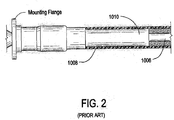
- These large dynamic application cables 1000 shown in Figures 2-3 typically include a combination of electrical wires, hydraulic lines and fiber optic cables 1006.
- the cables are fitted into a large diameter rubber hose 1008 which is often reinforced with steel wires or synthetic fibers 1009.
- a potting material 1010 to support the cable components against the inside diameter of the hose as shown for example in the prior art Figures 2 and 3 .
- One prior art solution to the traditional potted hose method outlined above is to provide a dynamic application cable assembly, including a cable and connection arrangement that incorporates several improved design features that collectively work to support not only the weight of the cable but also the dynamic loads experienced by the cable assembly without the need for the potted hose design.
- Such an arrangement may include a double-thick inner cable jacket with reinforced aramid fibers designed to carry the entire assembly load.
- the jacket thickness for drilling cables is equal to or greater than twice the thickness specified for such cables according to IEEE 1580, entitled "Recommended Practice for Marine Cable for Use on Shipboard and Fixed or Floating Facilities," incorporated herein by reference.
- the arrangement further includes a high-strength, high-dielectric resin chemically bonded to the inner jacket of the cable as well as to the assembly support flange.
- An overall metallic armor provides both secondary cable support and electrical grounding.
- a braid shielding for power cables provides a unique grounding arrangement within flange body itself.
- Such an arrangement can include a cable and flange assembly having at least one cable and at least one flange.
- the cable has an armor, a jacket and at least one conductor element therein.
- the flange includes a flange body, an arm or retainer and a grommet holder. The arm or of the cable is configured to be secured to the flange via the armor retainer.
- Figures 4A and 4B illustrate such a prior art flange 2000 having a flange body 2002, an armor retainer 2004, a grommet holder 2006, socket head cap screws 2008, a rubber grommet 2010, a shield terminator 2012, and a polymer fill port 2012.
- this flange design is an improvement over the potted hose arrangement, owing to the cable and flange's operation as a top drive service loop cable there are still continual forces such as bending, twisting, tension, compression, thermal loading, external pressure, and the like acting on the connection point between the flange body of the flange as it connects with the equipment elements.
- the flange body itself is dimensioned to replicate a standard pipe flange.
- the connected service loop cables experience many forces, both internal and external, during operation, which can result in "corkscrewing” as a result of trapped torsion within the cable. These forces can often lead to failure of the cable connection or cable conductors.
- the present arrangement corrects these issues by altering the shape of the flange body to include a plurality of circumferentially radiating lugs each spanning a given radial amount about the circumference of the flange body.
- a separate metal retaining ring is correspondingly constructed with lug retention slots, each spaning at least the same or a somewhat circumferentially larger amount of the circumference of the flange body than the lugs.
- the metal retaining ring is adapted to be fit onto the flange body with the lugs positioned with the lug slots and then the metal retention ring is attached or bolted to the support on either the top drive or derrick/platform.
- the metal retention ring is dimensioned, along with its lug slots to hold the flange body of the flange tightly against the support, thus supporting the full weight of the top drive service cable.
- the flange body may torsionally rotate against the support and within the metal retention ring (i.e. during top drive operation) while the metal retention ring continues to support the flange.
- the metal retaining ring is employed to attach the flange to a standard pipe flange bracket.
- a custom bracket may be employed with pre-machined lug slots as described above.
- FIGS. 5A - 5C show the exemplary basic structure top drive service cables used with a flange configured in accordance with various embodiments of the present invention.
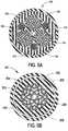
- Figure 5A illustrates an exemplary power cable 12A that includes an outer sheath 100, armoring 102, and a reinforcement layer 104 within jacket 106.
- power cable 12A has a shielding 110, encompassing the entirety of the conducting elements.
- shielding 110 there are primary ground wires 112 and conductors 114 (777KCMIL 1/C-- Kilo circular mils) forming the core of cable 12A.
- control cable 12B includes an outer sheath 200, armoring 202, and a reinforcement layer 204 within inner jacket 206.
- cable 12B Inside of inner jacket 206, cable 12B has a core binder 208 having a group of insulated conductors 210 and a central filler 212.
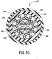
- auxiliary/instruments cable 12C includes an outer sheath 300, armor 302, and a reinforcement layer 304 within inner jacket 306. Inside of inner jacket 306, cable 12C has a series of electrical conductors 308, filler 310 and a central set of twisted pair communication cables 312 all held within binder 314.
- the present arrangement employs a different material for its armor than the prior art which is usually the standard armor of bronze or tinned copper.
- armor 102, 202 and 302 is constructed from 316 type stainless steel (standard molybdenum-bearing grade, austenitic stainless steel).
- Stainless steel armor such as 102, 202 and 302 serve three purposes: First, it protects cables 12A-12C from external damage. Second, it is designed in such a way that it also independently supports the weight of cables 12A-12C, along with a generous safety factor, when properly secured. Third, it guards against Electromagnetic Interference (EMI) when primary shielding is not provided between adjacent cables, when properly grounded electrically.
- EMI Electromagnetic Interference
- the cables 12A-12C work together with flange (described below) to create a durable cable which stands up to multiple flexations typically seen in dynamic applications such as on top drive service loops 11.
- Inner jackets 106, 206, 306 of each of cables 12A-12C is greater than or equal to the thickness specified for such cables according to standard IEEE 1580, and includes an aramid fiber reinforcement 104, 204, 304. According to this arrangement, when cables 12A-12C and their corresponding jackets 106, 206, 306 are properly secured to flanges 16, this reinforcement along with the thick jackets 106, 206, 306 allow the entire weight of cables 12A-12C to be supported by jackets 106, 206, 306, with a generous safety factor.
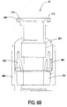
- FIG. 6A and 6B each illustrate a flange 16 ( figure 6A showing compression of the grommet 405) in accordance with one embodiment of the invention.
- Flange 16 has a flange body 400, armor retainer 402, and grommet holder 404.
- Flange body 400 while varying in dimensions for different cables 12A-12C serves the basic function of enabling inner jackets 106, 206, 306 of cables 12A-12C to be supported by means of a polymer bonding agent added through fill port 401 ( FIG. 6B ), The polymer bonding agent is designed to bond chemically with cable jackets such as 106, 206, 306.
- Flange body 400 has a void which, when filled with the polymer bonding agent, geometrically prevents cable 12 from being pulled through flange body 400 since the cured polymer gets bonded to cable jackets such as 106, 206, 306.
- Armor retainer 402 serves a dual purpose in each flange 16. First, armor retainer 402, works to secure stainless steel armors such as 102, 202, 302 so that the weight of cables 12A-12C may be supported by the stainless steel armor. Second, armor retainer 402 acts as an electrical ground path between stainless steel armor 102, 202, 302 and flange 16. Armor retainer 402 is secured to flange body 400 by means of socket head cap screws 403.
- Grommet holder 404 of flange 16 when screwed on to flange body 400, compresses a rubber grommet 405 ( FIG. 6B ) which then creates a seal within the interior of flange body 400. This not only prevents the ingress of water into flange 16A-16C but also prevents the polymer bonding agent from escaping during the pouring and subsequent curing process.
- flange 16 for power cable 12A has one additional item, namely a shield terminator 406.
- Shield terminator 406 secures shielding 110 of power cable 12A, which is typically created from tinned copper braid, and allows for a second electrical path for EMI shielding.
- Flange 16 may be advantageously made from a variety of materials depending on the application.
- High strength steel is typically used for land based applications (ASTM (American Society, for Testing and Materials) standards such as--A675, GR 70, 4140 HT, etc. - incorporated herein by reference), and stainless steel is predominantly used for applications where corrosion resistance is required (AISI (American Iron and Steel Institute) standards such as 316, AISI 304, etc - incorporated herein by reference).
- ASTM American Society, for Testing and Materials
- AISI American Iron and Steel Institute
- this additional support from the cured polymer is capable of independently supporting all cables 12A-12C within the entire cable assembly even if the stainless steel armor system were to fail.
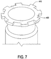
- flange body 400 is shown in Figure 7 with a series of lugs 410 in accordance with one embodiment. It is noted that lugs 410 and the related features described hereinafter may be used on a flange 16 as shown in Figures 6A and 6B , or alternatively on other flanges used in top drive service loops. To the extent such features of lugs 410 are described in connection with flange 16 the structure of flange 16 is considered exemplary.
- a flange body 400 maintains a series of lugs 410.
- the number of lugs 410 may be eight, each with an arc width of 20°.
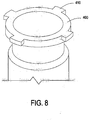
- lugs 410 are of the same size (20°), but they are only four lugs 410 present on the flange body 400.
- flange body 400 also has four lugs 410, but they are larger, e.g. 80°, covering a greater circumferential area.
- the size/circumferential arc of lugs 410 may be a matter of design depending on the desired expected weight load of the top drive service loop cable, as well as the degree of torsional freedom desired, as described below.
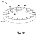
- a metal retention ring 420 is used as shown in Figure 10 .
- the retention ring is constructed of a similar material as the flange body 400, such as 4140 HT steel.
- Retention ring 420 has an outer ring 422 and a series of lug retention elements 424. Lug retention elements 424 have side walls 426 and a bottom lug retainer 428. In accordance with one embodiment, retention ring 420 includes a corresponding number of lug retention elements to match the number of lugs 410 in flange body 400. For example, retention ring 420 shown in Figure 10 has eight lug retention elements 424 corresponding for example to the eight lugs 410 on flange body 400 shown in Figure 7 .
- Figure 11 shows retention ring 420 with four lug retention elements 424 corresponding for example to the four lugs 410 on flange body 400 shown in Figure 8 .
- Figure 12 shows retention ring 420 with four larger lug retention elements 424 corresponding for example to the four larger lugs 410 on flange body 400 shown in Figure 9 .
- lugs 410 preferably have some rotational/torsional freedom as the two walls 426 of lug retention elements 424 are spaced farther apart than the arc size of the corresponding lugs 410. For example, if lugs 410 span an arc of 20° and lug retention elements 424 have walls 426 that span 30°, then flange body 400 and lugs 410 would have 10° (+/- 5°) of torsional freedom. If lug retention elements 424 have walls 426 than span 40°, using the same 20° lugs 410 then flange body 400 and lugs 410 would have 20° (+/- 10°) of torsional freedom.
- the amount of torsional freedom that is desired can be adjusted down to 0° of freedom (walls 426 spaced to the exact size of lugs 410) and up to 360° (+/- 180°) is desired (ring 420 having one retention element 424 with no walls 426 and one large lug retainer 428).
- typically lugs 410 preferable have between 10° (+/- 5°) - 40° (+/- 20°) of freedom within lug retainers.
- the amount of torsional freedom may be a matter of design depending on the desired expected weight load of the top drive service loop cable, and torsional flexibility of the cable.
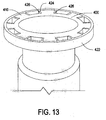
- Figure 13 shows flange 400 with lugs 410 and the retention ring 420 fitted thereover with lugs 410 contained within lug retention members 424.
- Retention ring 420 may then be bolted to the derrick or top drive support, preferably in the area between lug retention elements 424.
- lug retention elements 424 may be directly formed in similar style into a support 500 such as the support on a derrick or top drive equipment.
- a cap 502 may be placed over flange body 400 and bolted to support 500, locking flange body 400 and lugs 410 into their respective lug retention elements 420.
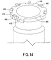
- retention elements 424 may be on the inside of support 500 (as shown in Figure 14 ) and thus cap 502 is not needed as flange body 400 is larger than the opening in support 500.
- this arrangement has the same function as flange retention ring 420, but builds its feature of lug retention members 424 directly into a custom support 500 (whereas flange retention ring 420 shown in Figure 13 can be used on existing/regular top drive service loop cable attachment supports).
- the connection to the derrick support and the top drive support allows for torsional movement of the flange/connection point.
- lugs 410 move within lug retention elements 420 with a given amount of rotational freedom. This absorbs some or all of the torsional stress imparted into the cable by the movement of the top drive within the derrick, without imparting it to the cable or flange elements extending the life of the cable and connection.
Landscapes
- Engineering & Computer Science (AREA)
- Life Sciences & Earth Sciences (AREA)
- Mining & Mineral Resources (AREA)
- Geology (AREA)
- Mechanical Engineering (AREA)
- General Engineering & Computer Science (AREA)
- Fluid Mechanics (AREA)
- Physics & Mathematics (AREA)
- Environmental & Geological Engineering (AREA)
- General Life Sciences & Earth Sciences (AREA)
- Geochemistry & Mineralogy (AREA)
- Structural Engineering (AREA)
- Civil Engineering (AREA)
- Architecture (AREA)
- Installation Of Indoor Wiring (AREA)
Abstract
Description
- The present invention relates to a cable assembly for drilling and mining type cables. More particularly, the present invention relates to a cable assembly and torsion relief mount, and method for making the same, for drilling and mining type cables.
- A dynamic application cable assembly, as differentiated from a static application cable, is one which may be subjected to one or more cyclical or continual forces such as bending, twisting, tension, compression, thermal loading, external pressure, and the like.
- Examples of such dynamic cable assemblies include top drive service loop cable assemblies for drilling rigs, bridle cable assemblies used on offshore tender vessels, and shuttle car cable assemblies used in mining operations.
Figure 1 shows a typical top drive service loop arrangement where a top driveservice loop cable 1000 connects between twosupports top drive equipment 1002 and the other on the derrick 1004 (for further connection to power and control equipment). These largedynamic application cables 1000 shown inFigures 2-3 typically include a combination of electrical wires, hydraulic lines and fiberoptic cables 1006. For protection, the cables are fitted into a largediameter rubber hose 1008 which is often reinforced with steel wires orsynthetic fibers 1009. Within this hose there is typically apotting material 1010 to support the cable components against the inside diameter of the hose as shown for example in the prior artFigures 2 and3 . - However, such designs are very heavy and relatively inflexible. In addition, they typically have a large outer diameter which often limits the effective bending radius of the assembly. While the prior art designs are workable, they are not ideal for the dynamic applications in which they are used. These cable assemblies are repeatedly subjected to moving forces, particularly bending and flexing, in which the size, weight, and relative stiffness of the assembly often limits its effective run life. Since the cable assembly is a vital link in the operation, top drive cable failure is costly, especially in drilling and mining operations where this translates into lost production, and typically hundreds of thousands of dollars per day in lost revenues.
- Additionally, these designs are generally not field-repairable and in most cases the cable assembly must be replaced when it is damaged. This has the potential impact of extending the down-time of the operation even further.
- One prior art solution to the traditional potted hose method outlined above is to provide a dynamic application cable assembly, including a cable and connection arrangement that incorporates several improved design features that collectively work to support not only the weight of the cable but also the dynamic loads experienced by the cable assembly without the need for the potted hose design.
- Such an arrangement may include a double-thick inner cable jacket with reinforced aramid fibers designed to carry the entire assembly load. For example, the jacket thickness for drilling cables is equal to or greater than twice the thickness specified for such cables according to IEEE 1580, entitled "Recommended Practice for Marine Cable for Use on Shipboard and Fixed or Floating Facilities," incorporated herein by reference. The arrangement further includes a high-strength, high-dielectric resin chemically bonded to the inner jacket of the cable as well as to the assembly support flange. An overall metallic armor provides both secondary cable support and electrical grounding. A braid shielding for power cables provides a unique grounding arrangement within flange body itself.
- Such an arrangement can include a cable and flange assembly having at least one cable and at least one flange. The cable has an armor, a jacket and at least one conductor element therein. The flange includes a flange body, an arm or retainer and a grommet holder. The arm or of the cable is configured to be secured to the flange via the armor retainer.
- For example
Figures 4A and4B illustrate such aprior art flange 2000 having aflange body 2002, anarmor retainer 2004, agrommet holder 2006, sockethead cap screws 2008, arubber grommet 2010, ashield terminator 2012, and apolymer fill port 2012. - Although this flange design is an improvement over the potted hose arrangement, owing to the cable and flange's operation as a top drive service loop cable there are still continual forces such as bending, twisting, tension, compression, thermal loading, external pressure, and the like acting on the connection point between the flange body of the flange as it connects with the equipment elements.
- For example, despite the use of such improved flange assemblies as shown in
Figure 4A and4B , the flange body itself is dimensioned to replicate a standard pipe flange. The connected service loop cables experience many forces, both internal and external, during operation, which can result in "corkscrewing" as a result of trapped torsion within the cable. These forces can often lead to failure of the cable connection or cable conductors. - Additionally, all prior art flanges, including those described above, still require that the flanges be properly aligned with their respective bolt holes on both sides (i.e. at both supports on either end of the cable). These bolt holes on the flanges and the respective supports are separated by long distances of 20-40m, making it difficult to achieve connection without adjusting or twisting the cable. By fixing these end flanges to their respective supports as shown for example in
Figure 1 , even slightly improper alignments, can induce torsional forces onto the cable assembly, which when subjected to dynamic forces during the top drive operation, can result in premature failure of the assembly. - The present arrangement corrects these issues by altering the shape of the flange body to include a plurality of circumferentially radiating lugs each spanning a given radial amount about the circumference of the flange body.
- In one embodiment a separate metal retaining ring is correspondingly constructed with lug retention slots, each spaning at least the same or a somewhat circumferentially larger amount of the circumference of the flange body than the lugs. The metal retaining ring is adapted to be fit onto the flange body with the lugs positioned with the lug slots and then the metal retention ring is attached or bolted to the support on either the top drive or derrick/platform. The metal retention ring is dimensioned, along with its lug slots to hold the flange body of the flange tightly against the support, thus supporting the full weight of the top drive service cable. Additionally, because the lug slots have a greater circumferential opening or span than the lugs of the flange body, the flange body may torsionally rotate against the support and within the metal retention ring (i.e. during top drive operation) while the metal retention ring continues to support the flange.
- In one embodiment the metal retaining ring is employed to attach the flange to a standard pipe flange bracket. Alternatively, a custom bracket may be employed with pre-machined lug slots as described above.
- The present invention can be best understood through the following description and accompanying drawings, wherein:
-
Figure 1 is an image of a prior art of a top drive service loop; -
Figure 2 is an image of a prior art top drive service loop cable; -
Figure 3 is an image of a prior art top drive service loop cable; -
Figures 4A and4B are images of a prior art top drive service loop cable flange; -
Figures 5A - 5C are images of a top drive service loop cable in accordance with one embodiment; -
Figures 6A and6B are images of a top drive service loop cable flange in accordance with one embodiment; -
Figure 7 is an image of a flange body with lugs in accordance with one embodiment; -
Figure 8 is an image of a flange body with lugs in accordance with one embodiment; -
Figure 9 is an image of a flange body with lugs in accordance with one embodiment; -
Figure 10 is an image of a flange body retention ring with lug retention elements in accordance with one embodiment; -
Figure 11 is an image of a flange body retention ring with lug retention elements in accordance with one embodiment; -
Figure 12 is an image of a flange body retention ring with lug retention elements in accordance with one embodiment; -
Figure 13 is an image of a flange body with lugs in a flange body retention ring with lug retention elements in accordance with one embodiment; and -
Figure 14 is an image of a flange body with lugs in a support with lug retention elements in accordance with one embodiment. - Beginning with the structure of the top drive service loop cables,
cables 12A-12C,Figures 5A - 5C show the exemplary basic structure top drive service cables used with a flange configured in accordance with various embodiments of the present invention. -
Figure 5A illustrates anexemplary power cable 12A that includes anouter sheath 100,armoring 102, and areinforcement layer 104 withinjacket 106. - Inside of
jacket 106,power cable 12A has ashielding 110, encompassing the entirety of the conducting elements. For example, inside shielding 110, there areprimary ground wires 112 and conductors 114 (777KCMIL 1/C-- Kilo circular mils) forming the core ofcable 12A. - As shown in
FIG. 5B , the basic structure ofcontrol cable 12B, includes anouter sheath 200, armoring 202, and areinforcement layer 204 withininner jacket 206. Inside ofinner jacket 206,cable 12B has acore binder 208 having a group ofinsulated conductors 210 and acentral filler 212. - As shown in
FIG. 5C , the basic structure of auxiliary/instruments cable 12C, includes anouter sheath 300,armor 302, and areinforcement layer 304 withininner jacket 306. Inside ofinner jacket 306,cable 12C has a series ofelectrical conductors 308,filler 310 and a central set of twistedpair communication cables 312 all held withinbinder 314. - In one embodiment, the present arrangement employs a different material for its armor than the prior art which is usually the standard armor of bronze or tinned copper. In one
arrangement armor cables 12A-12C from external damage. Second, it is designed in such a way that it also independently supports the weight ofcables 12A-12C, along with a generous safety factor, when properly secured. Third, it guards against Electromagnetic Interference (EMI) when primary shielding is not provided between adjacent cables, when properly grounded electrically. - In accordance with one embodiment, the
cables 12A-12C work together with flange (described below) to create a durable cable which stands up to multiple flexations typically seen in dynamic applications such as on top drive service loops 11.Inner jackets cables 12A-12C is greater than or equal to the thickness specified for such cables according to standard IEEE 1580, and includes anaramid fiber reinforcement cables 12A-12C and theircorresponding jackets flanges 16, this reinforcement along with thethick jackets cables 12A-12C to be supported byjackets -
Figures 6A and6B each illustrate a flange 16 (figure 6A showing compression of the grommet 405) in accordance with one embodiment of the invention.Flange 16 has aflange body 400,armor retainer 402, andgrommet holder 404.Flange body 400, while varying in dimensions fordifferent cables 12A-12C serves the basic function of enablinginner jackets cables 12A-12C to be supported by means of a polymer bonding agent added through fill port 401 (FIG. 6B ), The polymer bonding agent is designed to bond chemically with cable jackets such as 106, 206, 306.Flange body 400 has a void which, when filled with the polymer bonding agent, geometrically prevents cable 12 from being pulled throughflange body 400 since the cured polymer gets bonded to cable jackets such as 106, 206, 306. -
Armor retainer 402 serves a dual purpose in eachflange 16. First,armor retainer 402, works to secure stainless steel armors such as 102, 202, 302 so that the weight ofcables 12A-12C may be supported by the stainless steel armor. Second,armor retainer 402 acts as an electrical ground path betweenstainless steel armor flange 16.Armor retainer 402 is secured toflange body 400 by means of socket head cap screws 403. -
Grommet holder 404 offlange 16, when screwed on toflange body 400, compresses a rubber grommet 405 (FIG. 6B ) which then creates a seal within the interior offlange body 400. This not only prevents the ingress of water into flange 16A-16C but also prevents the polymer bonding agent from escaping during the pouring and subsequent curing process. - In one arrangement,
flange 16 forpower cable 12A has one additional item, namely ashield terminator 406.Shield terminator 406 secures shielding 110 ofpower cable 12A, which is typically created from tinned copper braid, and allows for a second electrical path for EMI shielding. -
Flange 16 may be advantageously made from a variety of materials depending on the application. High strength steel is typically used for land based applications (ASTM (American Society, for Testing and Materials) standards such as--A675, GR 70, 4140 HT, etc. - incorporated herein by reference), and stainless steel is predominantly used for applications where corrosion resistance is required (AISI (American Iron and Steel Institute) standards such as 316,AISI 304, etc - incorporated herein by reference). - Once the polymer cures and sets up within
flange 16 and also chemically bonds to the jackets such as 106, 206, 306 surrounding each of the individual conductors withincables 12A-12C, this additional support from the cured polymer is capable of independently supporting allcables 12A-12C within the entire cable assembly even if the stainless steel armor system were to fail. - Turning to the torsional relief aspect,
flange body 400 is shown inFigure 7 with a series oflugs 410 in accordance with one embodiment. It is noted that lugs 410 and the related features described hereinafter may be used on aflange 16 as shown inFigures 6A and6B , or alternatively on other flanges used in top drive service loops. To the extent such features oflugs 410 are described in connection withflange 16 the structure offlange 16 is considered exemplary. - In accordance with one embodiment, as illustrated in
Figure 7 , aflange body 400 maintains a series oflugs 410. In the illustrated instance the number oflugs 410 may be eight, each with an arc width of 20°. In another embodiment as shown infigure 8 , lugs 410 are of the same size (20°), but they are only fourlugs 410 present on theflange body 400. In another embodiment as shown infigure 9 ,flange body 400 also has fourlugs 410, but they are larger, e.g. 80°, covering a greater circumferential area. - The size/circumferential arc of
lugs 410 may be a matter of design depending on the desired expected weight load of the top drive service loop cable, as well as the degree of torsional freedom desired, as described below. - To connect
flange body 400 and lugs 410 to the support on the derrick or top drive service equipment, ametal retention ring 420 is used as shown inFigure 10 . The retention ring is constructed of a similar material as theflange body 400, such as 4140 HT steel. -
Retention ring 420 has anouter ring 422 and a series oflug retention elements 424.Lug retention elements 424 haveside walls 426 and abottom lug retainer 428. In accordance with one embodiment,retention ring 420 includes a corresponding number of lug retention elements to match the number oflugs 410 inflange body 400. For example,retention ring 420 shown inFigure 10 has eightlug retention elements 424 corresponding for example to the eightlugs 410 onflange body 400 shown inFigure 7 . -
Figure 11 showsretention ring 420 with fourlug retention elements 424 corresponding for example to the fourlugs 410 onflange body 400 shown inFigure 8 . -
Figure 12 showsretention ring 420 with four largerlug retention elements 424 corresponding for example to the fourlarger lugs 410 onflange body 400 shown inFigure 9 . - In each arrangement lugs 410 preferably have some rotational/torsional freedom as the two
walls 426 oflug retention elements 424 are spaced farther apart than the arc size of the corresponding lugs 410. For example, iflugs 410 span an arc of 20° and lugretention elements 424 havewalls 426 that span 30°, then flangebody 400 and lugs 410 would have 10° (+/- 5°) of torsional freedom. Iflug retention elements 424 havewalls 426 than span 40°, using the same 20°lugs 410 thenflange body 400 and lugs 410 would have 20° (+/- 10°) of torsional freedom. The amount of torsional freedom that is desired can be adjusted down to 0° of freedom (walls 426 spaced to the exact size of lugs 410) and up to 360° (+/- 180°) is desired (ring 420 having oneretention element 424 with nowalls 426 and one large lug retainer 428). However, typically lugs 410 preferable have between 10° (+/- 5°) - 40° (+/- 20°) of freedom within lug retainers. The amount of torsional freedom may be a matter of design depending on the desired expected weight load of the top drive service loop cable, and torsional flexibility of the cable. -
Figure 13 showsflange 400 withlugs 410 and theretention ring 420 fitted thereover withlugs 410 contained withinlug retention members 424.Retention ring 420 may then be bolted to the derrick or top drive support, preferably in the area betweenlug retention elements 424. - In another embodiment as shown in
Figure 14 , instead of using aseparate retention ring 420 fitted overlugs 410 andflange body 400, lugretention elements 424 may be directly formed in similar style into a support 500 such as the support on a derrick or top drive equipment. Afterlugs 410 are fitted intolug retention elements 424 with support 500, in one arrangement a cap 502 may be placed overflange body 400 and bolted to support 500, lockingflange body 400 and lugs 410 into their respectivelug retention elements 420. In another arrangement,retention elements 424 may be on the inside of support 500 (as shown inFigure 14 ) and thus cap 502 is not needed asflange body 400 is larger than the opening in support 500. - Essentially, this arrangement has the same function as
flange retention ring 420, but builds its feature oflug retention members 424 directly into a custom support 500 (whereasflange retention ring 420 shown inFigure 13 can be used on existing/regular top drive service loop cable attachment supports). - Owing to the above arrangement as described, as the top drive moves within the derrick, and as the top drive service loop cable correspondingly moves, the connection to the derrick support and the top drive support allows for torsional movement of the flange/connection point. As such, unlike the prior art where such torsional strains are imparted to the flange and cable elements, in the present arrangement, lugs 410 move within
lug retention elements 420 with a given amount of rotational freedom. This absorbs some or all of the torsional stress imparted into the cable by the movement of the top drive within the derrick, without imparting it to the cable or flange elements extending the life of the cable and connection. - While only certain features of the invention have been illustrated and described herein, many modifications, substitutions, changes or equivalents will now occur to those skilled in the art.
Claims (6)
- A flange assembly for supporting a cable comprising:a flange (16) for supporting a cable (12A; 12B; 12C) therein;a flange body (400) having one or more lugs (410) disposed about a circumference of said flange body (400); anda retention ring (420) dimensioned to fit over said flange body (400) and retain said flange assembly by connecting with said lugs (410).
- The flange assembly as claimed in claim 1, wherein said flange body (400) has a plurality of lugs (410).
- The flange assembly as claimed in claim 2, wherein said retention ring (420) has a plurality of lug retention elements (424) corresponding to said plurality of lugs (410).
- The flange assembly as claimed in claim 3, wherein said flange body (400) has a plurality of lugs (410).
- The flange assembly as claimed in claim 4, wherein said lugs (410) each have a first dimension spanning an arc of the circumference of the flange body (400) and said lug retention elements (424) each have a corresponding first dimension spanning an arc of the retention ring (420).
- The flange assembly as claimed in claim 5, wherein first dimension spanning an arc of the circumference of the flange body (400) of said lugs (410) is smaller than corresponding first dimension spanning an arc of the retention ring (420) of said lug retention elements (424).
Applications Claiming Priority (1)
| Application Number | Priority Date | Filing Date | Title |
|---|---|---|---|
| US15/857,023 US10591090B2 (en) | 2017-12-28 | 2017-12-28 | Top drive service loop clamp with torsional relief |
Publications (1)
| Publication Number | Publication Date |
|---|---|
| EP3505719A1 true EP3505719A1 (en) | 2019-07-03 |
Family
ID=64665790
Family Applications (1)
| Application Number | Title | Priority Date | Filing Date |
|---|---|---|---|
| EP18306611.7A Withdrawn EP3505719A1 (en) | 2017-12-28 | 2018-12-04 | Top drive service loop clamp with torsional relief |
Country Status (2)
| Country | Link |
|---|---|
| US (1) | US10591090B2 (en) |
| EP (1) | EP3505719A1 (en) |
Citations (6)
| Publication number | Priority date | Publication date | Assignee | Title |
|---|---|---|---|---|
| GB251960A (en) * | 1925-05-11 | 1926-09-16 | Siemens Schuckertwerke Gmbh | Means for supplying current to electric motors sunk in bore holes |
| DE2505620A1 (en) * | 1975-02-11 | 1976-08-19 | Goeransson Bengt S | Connecting union for electrical tubular conduit - has holding sleeve over which flexible hose cover fits to exclude water |
| CA2464045A1 (en) * | 1994-02-17 | 1995-08-18 | Duramax, Inc. | Torque control device for rotary mine drilling machine |
| US20150318086A1 (en) * | 2014-04-30 | 2015-11-05 | Nexans | Dynamic application cable assembly and method for making the same |
| CN206250455U (en) * | 2015-10-09 | 2017-06-13 | 山一电机株式会社 | Connector for modular |
| US20170338641A1 (en) * | 2014-12-25 | 2017-11-23 | Autonetworks Technologies, Ltd. | Seal structure for multicore cable, and seal member |
Family Cites Families (5)
| Publication number | Priority date | Publication date | Assignee | Title |
|---|---|---|---|---|
| US6145597A (en) * | 1999-02-17 | 2000-11-14 | Camco International, Inc. | Method and apparatus for retaining a cable in a conduit |
| US6916988B1 (en) * | 2004-07-12 | 2005-07-12 | Bridgeport Fittings, Inc. | Electrical connector with frustro conical snap fit retaining ring |
| US7075007B2 (en) * | 2004-09-13 | 2006-07-11 | Bridgeport Fittings, Inc. | Snap fit electrical connector assembly with conical outer snap fit retainer and one or more internal snap fit wire retainers |
| US8210268B2 (en) * | 2007-12-12 | 2012-07-03 | Weatherford/Lamb, Inc. | Top drive system |
| US9677351B2 (en) * | 2012-09-18 | 2017-06-13 | Blackhawk Specialty Tools, Llc | Method and apparatus for anchoring casing and other tubular goods |
-
2017
- 2017-12-28 US US15/857,023 patent/US10591090B2/en active Active
-
2018
- 2018-12-04 EP EP18306611.7A patent/EP3505719A1/en not_active Withdrawn
Patent Citations (6)
| Publication number | Priority date | Publication date | Assignee | Title |
|---|---|---|---|---|
| GB251960A (en) * | 1925-05-11 | 1926-09-16 | Siemens Schuckertwerke Gmbh | Means for supplying current to electric motors sunk in bore holes |
| DE2505620A1 (en) * | 1975-02-11 | 1976-08-19 | Goeransson Bengt S | Connecting union for electrical tubular conduit - has holding sleeve over which flexible hose cover fits to exclude water |
| CA2464045A1 (en) * | 1994-02-17 | 1995-08-18 | Duramax, Inc. | Torque control device for rotary mine drilling machine |
| US20150318086A1 (en) * | 2014-04-30 | 2015-11-05 | Nexans | Dynamic application cable assembly and method for making the same |
| US20170338641A1 (en) * | 2014-12-25 | 2017-11-23 | Autonetworks Technologies, Ltd. | Seal structure for multicore cable, and seal member |
| CN206250455U (en) * | 2015-10-09 | 2017-06-13 | 山一电机株式会社 | Connector for modular |
Also Published As
| Publication number | Publication date |
|---|---|
| US10591090B2 (en) | 2020-03-17 |
| US20190203854A1 (en) | 2019-07-04 |
Similar Documents
| Publication | Publication Date | Title |
|---|---|---|
| US9035185B2 (en) | Top-drive power cable | |
| US5119457A (en) | High-performance electric power cable and connector system | |
| US11232886B2 (en) | Reinforced submarine power cable | |
| US6538198B1 (en) | Marine umbilical | |
| EP2294587B1 (en) | Power umbilical | |
| US20060193572A1 (en) | Power umbilical for deep water | |
| EP2567386B1 (en) | Power cable for top-drive drilling rig | |
| US20120234597A1 (en) | Power umbilical | |
| US11646132B2 (en) | Cable with lightweight tensile elements | |
| AU2009275328B2 (en) | Umbilical | |
| US11270812B2 (en) | Power umbilical with impact protection | |
| US9742179B2 (en) | Conduit and end fitting for offshore cable assembly | |
| US20230126536A1 (en) | Power cable, method for production and use thereof | |
| US9449737B2 (en) | Dynamic application cable assembly and method for making the same | |
| US10591090B2 (en) | Top drive service loop clamp with torsional relief | |
| US20150167782A1 (en) | Braided termination for fiber subsea umbilical line | |
| WO2018052311A1 (en) | Umbilical fluid line, umbilical, and method | |
| US10801645B2 (en) | Dynamic application cable assembly with adjustable armor clamp | |
| EP3089298B1 (en) | Reinforcement arrangement for submarine cable junctions | |
| CN122025245A (en) | High-tensile towing cable for ocean engineering and preparation method thereof | |
| US20190025448A1 (en) | Hose assembly for underwater use | |
| CN118800507A (en) | Submarine cables and submarine cable modules |
Legal Events
| Date | Code | Title | Description |
|---|---|---|---|
| PUAI | Public reference made under article 153(3) epc to a published international application that has entered the european phase |
Free format text: ORIGINAL CODE: 0009012 |
|
| STAA | Information on the status of an ep patent application or granted ep patent |
Free format text: STATUS: THE APPLICATION HAS BEEN PUBLISHED |
|
| AK | Designated contracting states |
Kind code of ref document: A1 Designated state(s): AL AT BE BG CH CY CZ DE DK EE ES FI FR GB GR HR HU IE IS IT LI LT LU LV MC MK MT NL NO PL PT RO RS SE SI SK SM TR |
|
| AX | Request for extension of the european patent |
Extension state: BA ME |
|
| STAA | Information on the status of an ep patent application or granted ep patent |
Free format text: STATUS: REQUEST FOR EXAMINATION WAS MADE |
|
| 17P | Request for examination filed |
Effective date: 20200103 |
|
| RBV | Designated contracting states (corrected) |
Designated state(s): AL AT BE BG CH CY CZ DE DK EE ES FI FR GB GR HR HU IE IS IT LI LT LU LV MC MK MT NL NO PL PT RO RS SE SI SK SM TR |
|
| STAA | Information on the status of an ep patent application or granted ep patent |
Free format text: STATUS: EXAMINATION IS IN PROGRESS |
|
| 17Q | First examination report despatched |
Effective date: 20200514 |
|
| GRAP | Despatch of communication of intention to grant a patent |
Free format text: ORIGINAL CODE: EPIDOSNIGR1 |
|
| STAA | Information on the status of an ep patent application or granted ep patent |
Free format text: STATUS: GRANT OF PATENT IS INTENDED |
|
| INTG | Intention to grant announced |
Effective date: 20201117 |
|
| RIN1 | Information on inventor provided before grant (corrected) |
Inventor name: WHITE, ROBERT |
|
| GRAS | Grant fee paid |
Free format text: ORIGINAL CODE: EPIDOSNIGR3 |
|
| STAA | Information on the status of an ep patent application or granted ep patent |
Free format text: STATUS: THE APPLICATION IS DEEMED TO BE WITHDRAWN |
|
| 18D | Application deemed to be withdrawn |
Effective date: 20210330 |