EP3505696A1 - Automated window for installation in an inclined roof - Google Patents
Automated window for installation in an inclined roof Download PDFInfo
- Publication number
- EP3505696A1 EP3505696A1 EP18150103.2A EP18150103A EP3505696A1 EP 3505696 A1 EP3505696 A1 EP 3505696A1 EP 18150103 A EP18150103 A EP 18150103A EP 3505696 A1 EP3505696 A1 EP 3505696A1
- Authority
- EP
- European Patent Office
- Prior art keywords
- window
- actuator
- window sash
- side member
- sash
- Prior art date
- Legal status (The legal status is an assumption and is not a legal conclusion. Google has not performed a legal analysis and makes no representation as to the accuracy of the status listed.)
- Granted
Links
Images




Classifications
-
- E—FIXED CONSTRUCTIONS
- E04—BUILDING
- E04B—GENERAL BUILDING CONSTRUCTIONS; WALLS, e.g. PARTITIONS; ROOFS; FLOORS; CEILINGS; INSULATION OR OTHER PROTECTION OF BUILDINGS
- E04B7/00—Roofs; Roof construction with regard to insulation
- E04B7/18—Special structures in or on roofs, e.g. dormer windows
-
- E—FIXED CONSTRUCTIONS
- E04—BUILDING
- E04D—ROOF COVERINGS; SKY-LIGHTS; GUTTERS; ROOF-WORKING TOOLS
- E04D13/00—Special arrangements or devices in connection with roof coverings; Protection against birds; Roof drainage ; Sky-lights
- E04D13/03—Sky-lights; Domes; Ventilating sky-lights
- E04D13/035—Sky-lights; Domes; Ventilating sky-lights characterised by having movable parts
- E04D13/0351—Sky-lights; Domes; Ventilating sky-lights characterised by having movable parts the parts pivoting about a fixed axis
- E04D13/0354—Sky-lights; Domes; Ventilating sky-lights characterised by having movable parts the parts pivoting about a fixed axis the parts being flat
-
- E—FIXED CONSTRUCTIONS
- E04—BUILDING
- E04D—ROOF COVERINGS; SKY-LIGHTS; GUTTERS; ROOF-WORKING TOOLS
- E04D13/00—Special arrangements or devices in connection with roof coverings; Protection against birds; Roof drainage ; Sky-lights
- E04D13/03—Sky-lights; Domes; Ventilating sky-lights
- E04D13/035—Sky-lights; Domes; Ventilating sky-lights characterised by having movable parts
- E04D13/0357—Sky-lights; Domes; Ventilating sky-lights characterised by having movable parts the parts pivoting about an axis supported on a hinged frame or arms
-
- E—FIXED CONSTRUCTIONS
- E05—LOCKS; KEYS; WINDOW OR DOOR FITTINGS; SAFES
- E05F—DEVICES FOR MOVING WINGS INTO OPEN OR CLOSED POSITION; CHECKS FOR WINGS; WING FITTINGS NOT OTHERWISE PROVIDED FOR, CONCERNED WITH THE FUNCTIONING OF THE WING
- E05F15/00—Power-operated mechanisms for wings
- E05F15/60—Power-operated mechanisms for wings using electrical actuators
- E05F15/603—Power-operated mechanisms for wings using electrical actuators using rotary electromotors
- E05F15/611—Power-operated mechanisms for wings using electrical actuators using rotary electromotors for swinging wings
-
- E—FIXED CONSTRUCTIONS
- E05—LOCKS; KEYS; WINDOW OR DOOR FITTINGS; SAFES
- E05F—DEVICES FOR MOVING WINGS INTO OPEN OR CLOSED POSITION; CHECKS FOR WINGS; WING FITTINGS NOT OTHERWISE PROVIDED FOR, CONCERNED WITH THE FUNCTIONING OF THE WING
- E05F15/00—Power-operated mechanisms for wings
- E05F15/60—Power-operated mechanisms for wings using electrical actuators
- E05F15/603—Power-operated mechanisms for wings using electrical actuators using rotary electromotors
- E05F15/611—Power-operated mechanisms for wings using electrical actuators using rotary electromotors for swinging wings
- E05F15/63—Power-operated mechanisms for wings using electrical actuators using rotary electromotors for swinging wings operated by swinging arms
- E05F2015/631—Power-operated mechanisms for wings using electrical actuators using rotary electromotors for swinging wings operated by swinging arms the end of the arm sliding in a track; Slider arms therefor
-
- E—FIXED CONSTRUCTIONS
- E05—LOCKS; KEYS; WINDOW OR DOOR FITTINGS; SAFES
- E05Y—INDEXING SCHEME ASSOCIATED WITH SUBCLASSES E05D AND E05F, RELATING TO CONSTRUCTION ELEMENTS, ELECTRIC CONTROL, POWER SUPPLY, POWER SIGNAL OR TRANSMISSION, USER INTERFACES, MOUNTING OR COUPLING, DETAILS, ACCESSORIES, AUXILIARY OPERATIONS NOT OTHERWISE PROVIDED FOR, APPLICATION THEREOF
- E05Y2900/00—Application of doors, windows, wings or fittings thereof
- E05Y2900/10—Application of doors, windows, wings or fittings thereof for buildings or parts thereof
- E05Y2900/13—Type of wing
- E05Y2900/148—Windows
- E05Y2900/152—Roof windows
-
- E—FIXED CONSTRUCTIONS
- E05—LOCKS; KEYS; WINDOW OR DOOR FITTINGS; SAFES
- E05Y—INDEXING SCHEME ASSOCIATED WITH SUBCLASSES E05D AND E05F, RELATING TO CONSTRUCTION ELEMENTS, ELECTRIC CONTROL, POWER SUPPLY, POWER SIGNAL OR TRANSMISSION, USER INTERFACES, MOUNTING OR COUPLING, DETAILS, ACCESSORIES, AUXILIARY OPERATIONS NOT OTHERWISE PROVIDED FOR, APPLICATION THEREOF
- E05Y2900/00—Application of doors, windows, wings or fittings thereof
- E05Y2900/10—Application of doors, windows, wings or fittings thereof for buildings or parts thereof
- E05Y2900/13—Type of wing
- E05Y2900/148—Windows
- E05Y2900/152—Roof windows
- E05Y2900/154—Skylights
Definitions
- the disclosure relates to a window adapted for being installed in an inclined roof.
- the window comprises a window frame in which a top-hinged upper window sash and a bottom-hinged lower window sash are installed.
- the window further comprises collapsible side railings connected to the window frame and the lower window sash. The side railings are collapsed when the lower window sash is in the closed position and extended when the lower window sash is in the open position.
- Balcony roof windows having a window frame, an upper window sash, and a lower window sash may be a cost effective and labor efficient substitute for a traditional balcony.
- the space closest to the roof foot can be used as a balcony when the window sashes are opened outwards.
- the lower window sash functions as a balcony breast wall, while protective side railings, extending between frame and lower window sash, function as balcony side walls.
- EP0518988 discloses such a balcony roof window wherein the side railing is designed such that the window, in a relatively simple manner, can be adapted for being installed in inclined roof surfaces of varying inclinations.
- a roof window is adapted for being installed in an inclined roof, the window comprising a window frame in which a top-hinged upper window sash and a bottom-hinged lower window sash are installed, the window frame comprising a top member, a bottom member, and at least two side members, each window sash comprising a top member, a bottom member, and two side members, the upper window sash being hinged adjacent to the window frame top member by means of at least one hinge mechanism, the lower window sash being hinged adjacent to the window frame bottom member by means of at least one hinge mechanism, each window sash being adapted for pivoting between at least one open position and a closed position, the roof window further comprising two collapsible side railings, each side railing being connected to a window frame side member and a lower window sash side member, the side railings being collapsed when the lower window sash is in the closed position and extended when the lower window sash is in the open position(s), at least
- Providing one, or both, sash(es) of a roof window with electrically driven actuators facilitates automatic opening and closing of the window. This is not only a comfortable solution for everyday use, but especially advantageous for persons having difficulties manoeuvring a window manually. It is also an advantage seen from an environmental perspective, since the window can be set to open or close automatically, e.g. preventing the window being left open unintentionally. A further advantage from a safety perspective is automatic closing due to weather conditions such as wind or rain. Since at least one actuator part extends in parallel with window frame side member, this part does not protrude into the interior of the building. Such a solution is not visible from the interior, at least when the window is closed, providing a more aesthetic window.
- the roof window further comprises at least one electrically driven upper actuator, comprising an electric drive motor, arranged to pivot the upper window sash between the open and closed positions, allowing both window sashes to be operated automatically.
- at least one electrically driven upper actuator comprising an electric drive motor, arranged to pivot the upper window sash between the open and closed positions, allowing both window sashes to be operated automatically.
- the first hand rail end is slidingly and pivotally connected to the lower window sash side member, and the second hand rail end is pivotally connected to the window frame side member, allowing another simple solution for moving the lower window sash, and the side railing, along the window frame.
- the side rail is arranged, at least partially, along an outer side of the window frame side member, providing a window in which the side rail is invisible from the inside.
- the hand rail is arranged such that it is offset past a front face of the window frame, when the lower window sash is in the closed position, allowing the roof window be provided with standard window frame elements since the provision of a hand rail does not affect the external dimensions of the window.
- the lower window sash side member comprises at least one flashing, a part of the flashing covering a gap between the lower window sash side member and an adjacent window frame side member, providing a waterproof seal of the gap towards the interior.
- At least one of the first and second actuator parts is arranged inside the window frame side member, improving the aesthetics of the window and protecting the electric components.
- the first and second actuator parts extend in parallel with the window frame side member such that the actuator parts do not protrude past the external dimensions of the side member, in a direction perpendicular to a face of the window frame, when the lower window sash is in the closed position.
- Such a solution is invisible from the interior of the room when the window is closed, providing a more aesthetic window.
- At least one of the hinge mechanisms is integral with the electrically driven upper actuator and/or the electrically driven lower actuator, allowing a hinge mechanism which is invisible as well as reinforced by the actuator.
- the first actuator part is stationary and the second actuator part is moveable. This way, the more stable housing of the actuator may be fixedly and securely attached to the window frame, providing a stable solution.
- the second actuator part is connected to either the lower window sash, which increases the simplicity of the solution, or to the second hand rail end, allowing the actuator to both operate a hand rail lock and pivot the sash, sequentially.
- the lower actuator comprising a spindle actuator.
- a spindle actuator is a well-tried and reliable solution.
- a linkage mechanism is arranged between the lower window sash and the second actuator part.
- the use of an intermediate linkage mechanism allows the actuator to connect to any suitable part of the lower window sash, increasing the flexibility of the solution.
- the lower actuator comprises a chain actuator, the first actuator part being an actuator housing.
- a chain actuator is a highly cost-effective solution which has a strong holding/locking force when the sash is closed.
- Fig. 1 shows a schematic perspective view of a first embodiment of a roof window, wherein the roof window is in a fully open position.
- Fig. 2 shows the same roof window from the side and in a closed position.
- the roof window 1 is a so-called balcony window which is to be installed in an inclined roof.
- the roof window 1 comprises a window frame 2, which is to be installed in the roof such that the plane of the window frame 2 substantially aligns with the plane of the roof.
- a top-hinged upper window sash 3 and a bottom-hinged lower window sash 4 are installed in the window frame 2.
- the window frame 2 comprises a top member 2a, a bottom member 2b, and at least two side members 2c, 2d, each side member extending between the top member and the bottom member.
- Each window sash 3, 4 comprises a top member 3a, 4a, a bottom member 3b, 4b, and two side members 3c, 3d, 4c, 4d.
- Each window frame side member 2c, 2d may comprise an upper side member part 2ca, 2da and a lower side member part 2cb, 2db, the upper side member part 2ca, 2da extending in parallel with the upper window sash 3 and the lower side member part 2cb, 2db extending in parallel with the lower window sash 4, when the upper and lower window sashes 3, 4 are in the closed position.
- the window frame in this embodiment, is essentially divided into an upper U-shaped part and a lower U-shaped part.
- the top member 3a of the upper window sash 3 is hinged, by means of at least one hinge mechanism 13, adjacent to the top member 2a of the window frame 2a, and the bottom member 4b of the lower window sash 4 is hinged, by means of at least one similar hinge mechanism 13, adjacent to the bottom member 2b of the window frame 2.
- the window sash top members 3a, 4a, the window frame top member 2a, the window sash bottom members 3b, 4b, and the window frame bottom member 2b in other words, extend in parallel with each other.
- the upper window sash 3 is connected to the window frame 2 such that it can be pivoted between at least one open position, shown in Figs. 1 and 3-9 , and a closed position, shown in Fig. 2 .
- the lower window sash 4 is, correspondingly, connected to the window frame 2 such that it can be pivoted between at least one open position, shown in Figs. 1 and 3-9 , and a closed position, shown in Fig. 2 .
- the lower window sash 4 may, simultaneously with the pivoting movement, be moved obliquely downwards from the bottom member 2b of the window frame 2.
- the lower window sash 4 is hinged adjacent to the bottom member 2b of the window frame 2 in such a way that the bottom member 4b of the lower window sash 4 is displaced downwards from the bottom member of the window frame 2b and substantially parallel to the plane of the window frame 2, when being opened, while correspondingly being displaced upwards towards the bottom member of the window frame 2b and substantially parallel to the plane of the window frame 2, when being closed.
- the side railing 6 comprises a hand rail 7 with a first hand rail end 7a which is pivotally connected to an upper section of a lower window sash side member 4c, 4d.
- the opposite, second hand rail end 7b is pivotally and slidably connected to the window frame side member 2c, 2d.
- the hand rail 7 When the lower window sash 4 is moved from the open position to the closed position, the hand rail 7 is collapsed such that the first hand rail end 7a pivots on the lower window sash side member 4c, 4d, while the second hand rail end 7b pivots on, and slides along, the window frame side member 2c, 2d in a direction from the lower window sash 3, see Figs. 3 and 4 .
- the side rail 6, including the hand rail 7, is arranged along an outer side of the window frame side member 2c, 2d such that the side rail 6 extends, substantially, in parallel with the window frame side member 2c, 2d when the lower window sash is in the closed position.
- the side rail 6, is arranged at least partially in the gap between the lower window sash side member 4c, 4d and the adjacent window frame side member 2c, 2d, i.e. along an inner side of the window frame side member 2c, 2d such that the side rail 6 extends, substantially, in parallel with the window frame side member 2c, 2d when the lower window sash is in the closed position.
- a passive lock can be engaged and/or released by the second actuator part 9b, 10b, e.g. by guiding a pin in a groove with a locking path toward the end.
- An active lock can be engaged and/or released by a discrete electric means such as a magnet, a solenoid, or a small motor. Such electric means are preferably arranged on the window frame side member 2c, 2d.
- the lock may further be configured for manual override such that a person can, at least, release the lock without the use of electricity, e.g. by means of a lever or a pin.
- the first actuator part 10a and the second actuator part 10b both extend along the window frame side member 2c, 2d, in the longitudinal direction of the frame side member 2c, 2d, and are both substantially parallel with the inner and outer sides of the window frame side members 2c, 2d, regardless of the position of the lower window sash 4.
- the first actuator part 10a is secured to a side member 2c, 2d of the window frame 2, while the second actuator part 10b is slidingly connected to the first actuator part 10a. Further, one end of the second actuator part 10b is pivotally connected to the second hand rail end 7b.
- the lower actuator 10 of the lower window sash 4 is a chain actuator, also referred to as a push-pull chain actuator.
- the major part of the second actuator part 10b is pushed out of the first actuator part 10a towards an end stop defined during window installation.
- the second actuator part 10b is pulled towards the interior of the first actuator part 10a, in a direction towards the top member 2a of the window frame 2.
- the movement of the linkage mechanism 8 causes the lower window sash 3 to pivot inwards towards the plane of the window frame 2, Subsequently, the second hand rail end 7b is moved in the same direction.
- the entire side railing 6 is turned/folded into the window frame 2 such that it is substantially aligned with the plane of the window frame 2, as shown in Fig. 2 .
- the first actuator part/wire and windup 10a is connected to both a window frame side member 2c, 2d and to a second hand rail end 7b.
- One end of the second actuator part/resilient mechanism 10b is pivotally connected to a window frame side member 2c, 2d and the other end of the second actuator part/resilient mechanism 10b is pivotally connected to the lower window sash 4.
Landscapes
- Engineering & Computer Science (AREA)
- Architecture (AREA)
- Civil Engineering (AREA)
- Structural Engineering (AREA)
- Physics & Mathematics (AREA)
- Electromagnetism (AREA)
- Power-Operated Mechanisms For Wings (AREA)
Abstract
Description
- The disclosure relates to a window adapted for being installed in an inclined roof. The window comprises a window frame in which a top-hinged upper window sash and a bottom-hinged lower window sash are installed. The window further comprises collapsible side railings connected to the window frame and the lower window sash. The side railings are collapsed when the lower window sash is in the closed position and extended when the lower window sash is in the open position.
- Over the years, few houses were built with roof windows since the volume directly underneath the roof, the attic, usually was to be used for storage or not at all. Today, however, due to e.g. a severe lack of housing, attic spaces are often rebuilt into functional homes or offices. When rebuilding, roof windows of different variants are usually installed. It may also be desirable to provide the new home or office with a balcony. Adding a traditional balcony to an existing building is an expensive and labor intense process, as it requires significant modification of the roof, e.g. affecting the roof trusses.
- Balcony roof windows, having a window frame, an upper window sash, and a lower window sash may be a cost effective and labor efficient substitute for a traditional balcony. When installing the frame of a roof window at a sufficiently low height above the floor, the space closest to the roof foot can be used as a balcony when the window sashes are opened outwards. When open, the lower window sash functions as a balcony breast wall, while protective side railings, extending between frame and lower window sash, function as balcony side walls.
-
EP0518988 discloses such a balcony roof window wherein the side railing is designed such that the window, in a relatively simple manner, can be adapted for being installed in inclined roof surfaces of varying inclinations. - There is a constant need for improving the design of balcony roof window arrangements in order to achieve a balcony roof window which is environmentally friendly in both design and function, and which is easy to operate for everyone, including disabled persons.
- It is an object to mitigate the above problems, and to provide a window with two easily and efficiently operated window sashes.
- The foregoing and other objects are achieved by the features of the independent claim. Further implementation forms are apparent from the dependent claims, the description, and the figures.
- According to a first aspect, a roof window is adapted for being installed in an inclined roof, the window comprising a window frame in which a top-hinged upper window sash and a bottom-hinged lower window sash are installed, the window frame comprising a top member, a bottom member, and at least two side members, each window sash comprising a top member, a bottom member, and two side members, the upper window sash being hinged adjacent to the window frame top member by means of at least one hinge mechanism, the lower window sash being hinged adjacent to the window frame bottom member by means of at least one hinge mechanism, each window sash being adapted for pivoting between at least one open position and a closed position, the roof window further comprising two collapsible side railings, each side railing being connected to a window frame side member and a lower window sash side member, the side railings being collapsed when the lower window sash is in the closed position and extended when the lower window sash is in the open position(s), at least one electrically driven lower actuator, comprising an electric drive motor, arranged to pivot the lower window sash between the open and closed positions, the lower actuator comprising a first actuator part and a second actuator part, at least one of the first and second actuator parts extending in parallel with the window frame side member when the lower window sash is in the open position, and the first and second actuator parts extending in parallel with the window frame side member when the lower window sash is in the closed position.
- Providing one, or both, sash(es) of a roof window with electrically driven actuators facilitates automatic opening and closing of the window. This is not only a comfortable solution for everyday use, but especially advantageous for persons having difficulties manoeuvring a window manually. It is also an advantage seen from an environmental perspective, since the window can be set to open or close automatically, e.g. preventing the window being left open unintentionally. A further advantage from a safety perspective is automatic closing due to weather conditions such as wind or rain. Since at least one actuator part extends in parallel with window frame side member, this part does not protrude into the interior of the building. Such a solution is not visible from the interior, at least when the window is closed, providing a more aesthetic window.
- In one possible implementation form of the first aspect, the roof window further comprises at least one electrically driven upper actuator, comprising an electric drive motor, arranged to pivot the upper window sash between the open and closed positions, allowing both window sashes to be operated automatically.
- In one further possible implementation form of the first aspect, each side railing comprises a hand rail extending in parallel with the lower window sash side member when the lower window sash is in the closed position, and extending perpendicular to the lower window sash side member when the lower window sash is in the open position, a first hand rail end being connected to the lower window sash side member and an opposite second hand rail end being connected to the window frame side member, one of the hand rail ends being slidingly and pivotally connected, and one of the hand rail ends being pivotally connected to the side members, allowing a simple solution for moving the lower window sash, and the side railing, along the window frame.
- In one further possible implementation form of the first aspect, the first hand rail end is slidingly and pivotally connected to the lower window sash side member, and the second hand rail end is pivotally connected to the window frame side member, allowing another simple solution for moving the lower window sash, and the side railing, along the window frame.
- In one further possible implementation form of the first aspect, the side rail is arranged, at least partially, along an outer side of the window frame side member, providing a window in which the side rail is invisible from the inside.
- In one further possible implementation form of the first aspect, the hand rail is arranged such that it is offset past a front face of the window frame, when the lower window sash is in the closed position, allowing the roof window be provided with standard window frame elements since the provision of a hand rail does not affect the external dimensions of the window.
- In one further possible implementation form of the first aspect, the lower window sash side member comprises at least one flashing, a part of the flashing covering a gap between the lower window sash side member and an adjacent window frame side member, providing a waterproof seal of the gap towards the interior.
- In one further possible implementation form of the first aspect, the hand rail is arranged such that it is offset past a front face of the window frame, when the lower window sash is in the closed position, allowing the provision of a hand rail without affecting the standard width of the window.
- In one further possible implementation form of the first aspect, the lower window sash side member comprises at least one flashing, a part of the flashing covering a gap between the lower window sash side member and an adjacent window frame side member such that a water-tight window is provided.
- In one further possible implementation form of the first aspect, the hand rail is arranged at least partially in the gap between the lower window sash side member and an adjacent window frame side member, allowing a hand rail which is less visible from the exterior of a building to be provided.
- In one further possible implementation form of the first aspect, at least one of the first and second actuator parts is arranged inside the window frame side member, improving the aesthetics of the window and protecting the electric components.
- In one further possible implementation form of the first aspect, at least one of the first and second actuator parts extends in parallel with the window frame side member such that the actuator part(s) do(es) not protrude past the external dimensions of the side member in a direction perpendicular to a face of the window frame, when the lower window sash is in the open position. When the actuator does not protrude past the extension of the window frame, there are no parts protruding into the interior of the room when the window sash is in being opened or in the open position.
- In one further possible implementation form of the first aspect, the first and second actuator parts extend in parallel with the window frame side member such that the actuator parts do not protrude past the external dimensions of the side member, in a direction perpendicular to a face of the window frame, when the lower window sash is in the closed position. Such a solution is invisible from the interior of the room when the window is closed, providing a more aesthetic window.
- In one further possible implementation form of the first aspect, at least one of the hinge mechanisms is integral with the electrically driven upper actuator and/or the electrically driven lower actuator, allowing a hinge mechanism which is invisible as well as reinforced by the actuator.
- In one further possible implementation form of the first aspect, the first actuator part is stationary and the second actuator part is moveable. This way, the more stable housing of the actuator may be fixedly and securely attached to the window frame, providing a stable solution.
- In one further possible implementation form of the first aspect, the second actuator part is connected to either the lower window sash, which increases the simplicity of the solution, or to the second hand rail end, allowing the actuator to both operate a hand rail lock and pivot the sash, sequentially.
- In one further possible implementation form of the first aspect, the lower actuator comprising a spindle actuator. A spindle actuator is a well-tried and reliable solution.
- In one further possible implementation form of the first aspect, a linkage mechanism is arranged between the lower window sash and the second actuator part. The use of an intermediate linkage mechanism allows the actuator to connect to any suitable part of the lower window sash, increasing the flexibility of the solution.
- In one further possible implementation form of the first aspect, the lower actuator comprises a chain actuator, the first actuator part being an actuator housing. A chain actuator is a highly cost-effective solution which has a strong holding/locking force when the sash is closed.
The above will be apparent from the drawings and the embodiments described below. - In the following detailed portion of the present disclosure, the aspects, embodiments, and implementations will be explained in more detail with reference to the example embodiments shown in the drawings, in which:
-
Fig. 1 shows a schematic perspective view of an embodiment of a roof window according to the present invention, wherein the roof window is in a fully open position. -
Fig. 2 shows a schematic side view of the roof window according toFig. 1 , wherein the roof window is in a closed position. -
Fig. 3 shows a schematic side view of the roof window according toFigs. 1 and 2 , wherein the roof window is in a partially open position. -
Fig. 4 shows a schematic side view of the roof window according toFigs. 1 to 3 , wherein the roof window is in fully open position. -
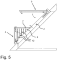
Fig. 5 shows a further embodiment of a roof window according to the present invention. -
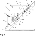
Fig. 6 shows a further embodiment of a roof window according to the present invention. -
Fig. 7 shows a further embodiment of a roof window according to the present invention. -
Fig. 8 shows a further embodiment of a roof window according to the present invention. -
Fig. 9 shows a further embodiment of a roof window according to the present invention. -
Fig. 10 shows a cross-sectional view of a further embodiment of a roof window according to the present invention. -
Fig. 11 shows a cross-sectional view of a further embodiment of a roof window according to the present invention. -
Fig. 1 shows a schematic perspective view of a first embodiment of a roof window, wherein the roof window is in a fully open position.Fig. 2 shows the same roof window from the side and in a closed position. - The
roof window 1 is a so-called balcony window which is to be installed in an inclined roof. Theroof window 1 comprises awindow frame 2, which is to be installed in the roof such that the plane of thewindow frame 2 substantially aligns with the plane of the roof. A top-hingedupper window sash 3 and a bottom-hingedlower window sash 4 are installed in thewindow frame 2. Thewindow frame 2 comprises atop member 2a, abottom member 2b, and at least twoside members window sash top member bottom member side members - Each window
frame side member upper window sash 3 and the lower side member part 2cb, 2db extending in parallel with thelower window sash 4, when the upper andlower window sashes - The
top member 3a of theupper window sash 3 is hinged, by means of at least onehinge mechanism 13, adjacent to thetop member 2a of thewindow frame 2a, and thebottom member 4b of thelower window sash 4 is hinged, by means of at least onesimilar hinge mechanism 13, adjacent to thebottom member 2b of thewindow frame 2. The window sashtop members frame top member 2a, the windowsash bottom members frame bottom member 2b, in other words, extend in parallel with each other. - The
upper window sash 3 is connected to thewindow frame 2 such that it can be pivoted between at least one open position, shown inFigs. 1 and3-9 , and a closed position, shown inFig. 2 . Thelower window sash 4 is, correspondingly, connected to thewindow frame 2 such that it can be pivoted between at least one open position, shown inFigs. 1 and3-9 , and a closed position, shown inFig. 2 . - The
lower window sash 4 may, simultaneously with the pivoting movement, be moved obliquely downwards from thebottom member 2b of thewindow frame 2. I.e., thelower window sash 4 is hinged adjacent to thebottom member 2b of thewindow frame 2 in such a way that thebottom member 4b of thelower window sash 4 is displaced downwards from the bottom member of thewindow frame 2b and substantially parallel to the plane of thewindow frame 2, when being opened, while correspondingly being displaced upwards towards the bottom member of thewindow frame 2b and substantially parallel to the plane of thewindow frame 2, when being closed. This movement may be achieved by hinging thebottom member 4b of thelower window sash 4, at both sides, to the lower end of a supporting lever which extends in parallel with the windowframe side member frame side members - Other pivotal joints may be used as well. Furthermore, the
lower window sash 4 may be provided with springs which are compressed by the pivotal joints when thewindow sash 4 is in the closed position, in order to reduce the force needed to pivot thelower window sash 4 open. - In the closed position, shown in
Fig. 2 , theupper window sash 3 and thelower window sash 4 are substantially aligned with each other and with the plane of thewindow frame 2 such that they cover the opening of thewindow frame 2. - However, there may be some overlap between the
upper window sash 3 and thelower window sash 4 in order to keep the window water-tight. In one embodiment, thebottom member 3b of theupper window sash 3 overlaps thetop member 4a of thelower window sash 4 when thewindow sashes - Further, the
upper window sash 3 may be configured to enter into locking engagement with thewindow frame 2 when theupper window sash 3 is in the closed position. - In the open position, the
upper window sash 3 and thelower window sash 4 may be arranged at acute angles α, β to the plane of thewindow frame 2, see for exampleFig. 4 . The acute angles α, β are adjustable during installment of the window, such that they can be adjusted to match horizontal and vertical sash positions in relation to the roof slope. Theupper window sash 3 may be arranged at a variety of angles α, from substantially just over 0°, 0° corresponding to a closed window sash, to an angle where thewindow sash 3 extends horizontally when installed in a roof, i.e. a balcony position as well as a range of ventilation positions. Thelower window sash 4, preferably, only has one open position at an angle β where thewindow sash 4 extends substantially vertically when installed in a roof, i.e. a balcony position. This is due to the fact that thelower window sash 4 functions as a balcony breast wall, wherefore the extension of thelower window sash 4 cannot deviate too much from the vertical plane. The openupper window sash 3 forms a roof which partly covers the balcony formed by thelower window sash 4 being opened outwards. - The
roof window 1 is further provided with twocollapsible side railings 6. Eachside railing 6 is connected to a windowframe side member lower window sash 4side member window frame 2 and thelower window sash 4 and functions as balcony side walls. Theside railings 6 are collapsible such that they fold into, or onto, thewindow frame 2 when thelower window sash 4 is in the closed position, and extend when thelower window sash 4 is in the open position. Eachside railing 6 comprises a plurality ofrods 12 and ahand rail 7. - In one embodiment, the
side railing 6 comprises ahand rail 7 with a firsthand rail end 7a which is pivotally connected to an upper section of a lower windowsash side member hand rail end 7b is pivotally and slidably connected to the windowframe side member - When the
lower window sash 4 is moved from the open position to the closed position, thehand rail 7 is collapsed such that the firsthand rail end 7a pivots on the lower windowsash side member hand rail end 7b pivots on, and slides along, the windowframe side member lower window sash 3, seeFigs. 3 and 4 . - In a further embodiment, the first
hand rail end 7a is pivotally and slidably connected to the windowsash side member hand rail end 7b is pivotably connected to the windowframe side member Fig. 5 . When thelower window sash 4 is moved from the open position to the closed position, thehand rail 7 is collapsed such that the firsthand rail end 7a both pivots on, and slides along, the lower windowsash side member sash bottom member 4b, while the secondhand rail end 7b pivots on the windowframe side member - The
hand rail 7 extends substantially perpendicular to the plane of thelower window sash 4, i.e. perpendicular to the lower windowsash side member lower window sash 4 is in the open position, i.e. horizontally when installed in a roof, as shown inFigs. 4-9 . Thehand rail 7 extends in parallel with the lower windowsash side member lower window sash 4 is in the closed position. - As mentioned above, as the
lower window sash 4 moves from the open position to the closed position, in one embodiment, the secondhand rail end 7b slides along the windowframe side member lower window sash 3, seeFigs. 3 and 4 , such that it eventually extends along and aligns with the windowframe side member Fig. 2 . In a further embodiment, the firsthand rail end 7a slides along the lower windowsash side member sash bottom member 4b, seeFig. 5 . - The
hand rail 7 is also connected to vertical rail bars 12 which, when moving thelower window sash 4 to its closed position, are folded from their vertical position into, or onto, thewindow frame 2 together with thehand rail 7, such that they also extend along and align with the windowframe side member hand rail 7 and the other end is adapted for sliding freely along the windowframe side member - The lower window
sash side member sash side member frame side member hand rail 7 and the lower windowsash side member hand rail 7. - In one embodiment, shown in
Fig. 10 , theside rail 6, including thehand rail 7, is arranged along an outer side of the windowframe side member side rail 6 extends, substantially, in parallel with the windowframe side member Fig. 11 , theside rail 6, is arranged at least partially in the gap between the lower windowsash side member frame side member frame side member side rail 6 extends, substantially, in parallel with the windowframe side member - The outer side of the window
frame side member frame side member roof window 1 is mounted. Correspondingly, the inner side if the windowframe side member frame side member window sash - Similarly, the front face F of the
window frame 2 is the face which is directed towards the exterior of a building, when theroof window 1 is mounted in the roof of the building, i.e. the front face F comprises the front sides of the window frame top, bottom, andside members roof window 1 is mounted in the roof of the building, i.e. the rear face R comprises the rear sides of the window frame top, bottom, andside members - In one embodiment, shown in
Fig. 10 , thehand rail 7 of theside railing 6 is arranged such that it is offset to protrude past the front face of thewindow frame 2, towards the exterior of a building when mounted in the roof of the building, when thelower window sash 4 is in the closed position. In a further embodiment, thehand rail 7 is arranged such that it does not protrude past the front face of thewindow frame 2, when thelower window sash 4 is in the closed position. - The
roof window 1 further comprises at least one electrically drivenlower actuator 10, which comprises anelectric drive motor 11, and which is adapted for pivoting thelower window sash 4 between open and closed positions. In one embodiment, theroof window 1 also comprises at least one electrically drivenupper actuator 9, comprising anelectric drive motor 11, and which is adapted for pivoting theupper window sash 3 between open and closed positions. In a further embodiment, the window is provided with oneupper actuator 9 and onelower actuator 10 per side. Both theupper actuator 9 and thelower actuator 10 are associated with thewindow frame 2, preferably aside member - At least one of the above-mentioned
hinge mechanisms 13 may be integral with the electrically drivenupper actuator 9 and/or the electrically drivenlower actuator 10. Thehinge mechanism 13 may be located within the structural housing of the upper orlower actuator - The
lower actuator 10 may be arranged at least partially within the windowframe side member frame side member lower actuator 10 is arranged such that it extends along the outer side of the windowframe side member hand rail 7 and/or theflashing 5 may be arranged above thelower actuator 10, such that the flashing extends between thehand rail 7 and thelower actuator 10. - In one embodiment, the
lower actuator 10 is arranged next to thesash side member sash side member lower actuator 10 are substantially in the same plane. - In a further embodiment, the
lower actuator 10 is arranged at least partially between the windowframe side member flashing 5. - The electrically driven
lower actuator 10 comprises afirst actuator part 10a and asecond actuator part 10b. Correspondingly, the electrically drivenupper actuator 9 comprises afirst actuator part 9a and asecond actuator part 9b. At least one of theactuator parts frame side member first actuator part second actuator part frame side member lower window sash 4 is in the closed position, i.e. do not protrude from the plane of thewindow frame 2. In one embodiment, at least one of thefirst actuator parts second actuator parts frame side member - The
second actuator part first actuator part first actuator part frame side members second actuator part frame side members window frame 2. - The
second actuator part 10b of the electrically drivenlower actuator 10 is connected to either thelower window sash 4 or to the secondhand rail end 7b. The connection may be made through a bracket, a chain, a link, and/or a hinge. - In one embodiment, at least one of the first and
second actuator parts frame side member actuator part side member window frame 2, when thelower window sash 4 is in the open position, seeFig. 10 . The external dimensions of the windowframe side member frame side member - In a further embodiment, both the first and
second actuator parts frame side member second actuator part side member window frame 2, when thelower window sash 4 is in the closed position. - The
lower window sash 4 may be maintained in its open position either by means of the self-locking effect of thelower actuator 10, or by means of a lock. The lock may be arranged in connection with a sliding hand rail end, e.g. ahand rail end 7b which is slidably connected to the windowframe side member hand rail end 7a which is slidably connected to the windowsash side member side railing 6/hand rail 7 in position when thelower window sash 4 is in the open position and theside rail 6 is extended, as shown inFigs. 4 to 9 . The lock may be active or passive, and configured to be released by a controller. A passive lock can be engaged and/or released by thesecond actuator part frame side member - The
upper actuator 9 and thelower actuator 10 may each comprise anelectric drive motor 11, operated by an electronic control unit. The electric drive motor has a feedback signal which establishes the position of the actuator. Theactuators window sashes - As mentioned above, the
upper window sash 3 may overlap thelower window sash 4 when in the closed position. Therefore, theactuators upper window sash 3 starts opening slightly before thelower window sash 4, and such that thelower window sash 4 arrives at the closed position slightly before theupper window sash 3. The electronic control unit is configured to initiate the pivoting movement of theupper window sash 3 from the closed position to the open position prior to initiating the pivoting movement of thelower window sash 4 from the closed position to said open position. - Correspondingly, the electronic control unit is configured to initiate the pivoting movement of the
lower window sash 4 from the open position to the closed position in relation to initiating the pivoting movement of theupper window sash 3 from the open position to the closed position in such a way that thelower window sash 4 arrives at its closed position before theupper window sash 3 arrives at its closed position. - In one embodiment, the electronic control unit is configured to initiate the pivoting movement of the
lower window sash 4 from the open position to the closed position prior to initiating the pivoting movement of theupper window sash 3 from the open position to the closed position, and thelower window sash 4 and theupper window sash 3 are moved at substantially equal speed. - In a further embodiment, the electronic control unit is configured to simultaneously initiate the pivoting movement of the
lower window sash 4 from the open position to the closed position and the pivoting movement of theupper window sash 3 from the open position to the closed position, while moving thelower window sash 4 to the closed position at a higher speed than theupper window sash 3. - In one embodiment, the
actuators upper window sash 3 and/or thelower window sash 4 when thewindow sash actuators window sash - In some embodiments, see
Figs. 6 and8 , thelower actuator 10 of thelower window sash 4 is a linear actuator, preferably a spindle actuator. A spindle actuator operated sash may have a dead extreme position, since the spindle force is low when the sash is in the closed position. Hence, a ramp guide may be employed to aid the sash movement at an almost closed position, i.e. to push the spindle away from the dead extreme position. Such a ramp guide may be operated by the same spindle actuator. - The
first actuator part 10a and thesecond actuator part 10b, shown inFig. 6 , both extend along the windowframe side member frame side member frame side members lower window sash 4. - The
first actuator part 10a is secured to aside member window frame 2, while thesecond actuator part 10b is slidingly connected to thefirst actuator part 10a. Further, one end of thesecond actuator part 10b is pivotally connected to the secondhand rail end 7b. - In the open position, the major part of the
second actuator part 10b is arranged within thefirst actuator part 10a. When moving thelower window sash 4 from the open position to the closed position, thesecond actuator part 10b is pushed outwards from within thefirst actuator part 10a, in a direction towards thetop member 2a of thewindow frame 2. Subsequently, the secondhand rail end 7b is moved in the same direction. The movement of thehand rail 7 causes thelower window sash 3 to pivot inwards towards the plane of thewindow frame 2, and theside railing 6 is folded into thewindow frame 2 such that it, eventually, is aligned with the plane of thewindow frame 2, as shown inFig. 2 . - In the closed position, the major part of the
second actuator part 10b extends from thefirst actuator part 10a. When moving thelower window sash 4 from the closed position to the open position, thesecond actuator part 10b is pulled inwards towards the interior of thefirst actuator part 10a, in a direction towards thebottom member 2b of thewindow frame 2. Subsequently, the secondhand rail end 7b is moved in the same direction. The movement of thehand rail 7 causes thelower window sash 3 to pivot outwards from the plane of thewindow frame 2, and theside railing 6 is extended such that thehand rail 7 eventually extends perpendicular to thelower window sash 4, i.e. horizontally when installed in a roof. - In a further embodiment, shown in
Fig. 7 , thelower actuator 10 of thelower window sash 4 is a chain actuator, also referred to as a push-pull chain actuator. - The
first actuator part 10a extends along the windowframe side member window frame 2 regardless of the position of thelower window sash 4. - The
first actuator part 10a, a housing, is fixed to aside member window frame 2 and extends along the windowframe side member frame side member second actuator part 10b, i.e. the chain, is connected to the interior of the first actuator part/housing 10a. The other end of the second actuator part/chain 10b is connected to thelower window sash 4. - In the open position, the main part of the second actuator part/
chain 10b is pushed out of the first actuator part/housing 10a. When moving thelower window sash 4 from the open position to the closed position, the second actuator part/chain 10b is pulled into the interior of the first actuator part/housing 10a, in a direction towards theside member window frame 2. The movement of the second actuator part/chain 10b causes thelower window sash 3 to pivot inwards towards the plane of thewindow frame 2, Subsequently, the secondhand rail end 7b is moved in the same direction. Theentire side railing 6 is turned/folded into thewindow frame 2 such that it is eventually aligned with the plane of thewindow frame 2, as shown inFig. 2 . - In the closed position, the main part of the second actuator part, i.e. the
chain 10b, is pulled into the first actuator part/housing 10a. Thechain 10b is stored in a magazine inside thehousing 10a and extends in parallel with the housing, possibly folded in multiple layers. When moving thelower window sash 4 from the closed position to the open position, the second actuator part/chain 10b is pushed outwards from the interior of the first actuator part/housing 10a, in a direction substantially perpendicular to plane of thewindow frame 2. The movement of thelower window sash 4 causes thehand rail end 7b to move in a direction towards thebottom member 2b of thewindow frame 2, and theside railing 6 is extended such that thehand rail 7 eventually extends perpendicular to thelower window sash 4, i.e. horizontally when installed in a roof. - In an additional embodiment, shown in
Fig. 8 , thelower actuator 10 of thelower window sash 4 is a linear actuator, preferably a spindle actuator. Thefirst actuator part 10a and thesecond actuator part 10b both extend along the windowframe side member window frame 2 regardless of the position of thelower window sash 4. - The
first actuator part 10a is fixed to aside member window frame 2, while thesecond actuator part 10b is slidingly connected to thefirst actuator part 10a. One end of the second actuator part is connected to thelower window sash 4 by means of alinkage mechanism 8 arranged between thelower window sash 4 and an end of thesecond actuator part 10b. Thelinkage mechanism 8 may provide both a pivot and a translatory displacement, such that when thelower window sash 4 is pivoted from the closed position to the open vertical position, its bottom may be displaced simultaneously. In other words, the pivot axis is translatorily displaced during the opening movement. This is, i.a., due to the water drain design of roof windows and a desire for better use of space.Such linkage mechanisms 8 may, e.g., be provided in the form of a scissor linkage, a parallelogram linkage mechanism, or a pivot hinge. Furthermore, the linkage mechanism may be provided with an arm slide whereby the pivot axis is displaced by the arm. Themovable actuator part 10b may act directly on thelinkage mechanism 8 to open and close thelower window sash 4. Themovable actuator part 10b may alternatively act on thelower sash 4. Thelinkage mechanism 8 disclosed in this embodiment is compatible with all other embodiments. Optionally, an actuator and/or spring acts on thelinkage mechanism 8. - In the open position, the major part of the
second actuator part 10b is pushed out of thefirst actuator part 10a towards an end stop defined during window installation. When moving thelower window sash 4 from the open position to the closed position, thesecond actuator part 10b is pulled towards the interior of thefirst actuator part 10a, in a direction towards thetop member 2a of thewindow frame 2. The movement of thelinkage mechanism 8 causes thelower window sash 3 to pivot inwards towards the plane of thewindow frame 2, Subsequently, the secondhand rail end 7b is moved in the same direction. Theentire side railing 6 is turned/folded into thewindow frame 2 such that it is substantially aligned with the plane of thewindow frame 2, as shown inFig. 2 . - In the closed position, the main part of the
second actuator part 10b is pulled into thefirst actuator part 10a towards the end stop. When moving thelower window sash 4 from the closed position to the open position, thesecond actuator part 10b is pushed outwards from the interior of thefirst actuator part 10a, in a direction towards thebottom member 2b of thewindow frame 2. The movement of thelower window sash 4 causes thehand rail end 7b to move in the same direction, and theside railing 6 is extended such that thehand rail 7 eventually extends perpendicular to thelower window sash 4, i.e. horizontally when installed in a roof. - In yet another embodiment, shown in
Fig. 9 , thelower actuator 10 of thelower window sash 4 is combination of a pull actuator and a push actuator. Thefirst actuator part 10a of saidlower actuator 10 is a pull actuator comprising a wire and a windup mechanism. Thesecond actuator part 10b of saidlower actuator 10 is a push actuator comprising a resilient mechanism such as e.g. a gas spring. - The first actuator part/wire and
windup 10a is connected to both a windowframe side member hand rail end 7b. One end of the second actuator part/resilient mechanism 10b is pivotally connected to a windowframe side member resilient mechanism 10b is pivotally connected to thelower window sash 4. - The windup is fixedly connected to the window
frame side member hand rail end 7b. - The first actuator part/wire and
windup 10a of is adapted for only moving thelower window sash 4 from the open position to the closed position. The second actuator part/resilient mechanism 10b is, on the other hand, adapted for only moving thelower window sash 4 from the closed position to the open position. Thepush actuator 10b and thepull actuator 10a can also be arranged in other ways. For example the push actuator may be provided by the same spring which aids opening the lower sash. Such spring may be connected to the bottom hinge or to the rail. For example the pull actuator needs not be connected to therail 7, but it may be connected to the lower sash. - In the open position, the wire of the
first actuator part 10a is wound out and the second actuator part/resilient means 10b is arranged at an angle to the plane of thewindow frame 2 so as to push thelower window sash 4 outwards and hold it in open position. When moving thelower window sash 4 from the open position to the closed position, the wire of thefirst actuator part 10a is wound up onto the windup mechanism of thefirst actuator part 10a. As the wire is wound up, it pulls the secondhand rail end 7b in a direction towards thetop member 2a of thewindow frame 2. The movement of thehand rail 7 causes thelower window sash 3 to pivot inwards towards the plane of thewindow frame 2, and theside railing 6 is turned/folded into thewindow frame 2 such that it is substantially aligned with the plane of thewindow frame 2, as shown inFig. 2 . The pulling force provided by the first actuator part/wire andwindup 10a is larger than the pushing force provided by the second actuator part/resilient mechanism 10b, and therefore the second actuator part/resilient mechanism 10b is pressed together and moved to a position where it stores energy and optionally aligns with the plane of thewindow frame 2. - The
first actuator part 10a may be similar to that which is shown inEP2957700 . Such an actuator may be operated by means of the previously mentioned electronic control unit, and it is also possible to extend and withdraw manually (e.g. it is not self-locking) due to the wind up drum which is spring loaded and rotated by a one-way clutch motor. Thefirst actuator part 10 may also be a motorised drum that withdraws and winds up the wire. - In the closed position, the wire of the
first actuator part 10a is wound up and resting on the windup without applying substantial force to thelower window sash 3. The second actuator part/resilient means 10b is pressed together. When activating the second actuator part/resilient means 10b such that it expands and hence pivots, thelower window sash 4 is moved from the closed position to the open position. The second actuator part/resilient means 10b is preferably activated by means of an electrically releasable lock or by withdrawal of the wire, and moved from its closed position to a position which is at an angle to the plane of thewindow frame 2. As the second actuator part/resilient means 10b is activated, its push force is applied onto thelower window sash 4 such that thelower window sash 4 is pivoted outwards and thereafter held in open position. As thelower window sash 4 moves, thehand rail end 7b moves in a direction towards thebottom member 2b of thewindow frame 2. As thehand rail end 7b moves, the wire of thefirst actuator part 10a is wound out from the windup mechanism of thefirst actuator part 10a. At the same time, theside railing 6 is extended such that thehand rail 7 eventually extends perpendicular to thelower window sash 4, i.e. horizontally when installed in a roof. - The second actuator part/
resilient means 10b acts automatically and moves thelower window sash 4 towards the open position. The second actuator part/resilient means 10b can be closed manually by means of human force or electrically by means of force from thefirst actuator part 10a, e.g. wire windup. - The various aspects and implementations have been described in conjunction with various embodiments herein. However, other variations to the disclosed embodiments can be understood and effected by those skilled in the art in practicing the claimed subject-matter, from a study of the drawings, the disclosure, and the appended claims. In the claims, the word "comprising" does not exclude other elements or steps, and the indefinite article "a" or "an" does not exclude a plurality. The mere fact that certain measures are recited in mutually different dependent claims does not indicate that a combination of these measured cannot be used to advantage.
- The reference signs used in the claims shall not be construed as limiting the scope.
Claims (19)
- A roof window (1) adapted for being installed in an inclined roof, said window (1) comprising
a window frame (2) in which a top-hinged upper window sash (3) and a bottom-hinged lower window sash (4) are installed, said window frame (2) comprising a top member (2a), a bottom member (2b), and at least two side members (2c, 2d), each window sash (3, 4) comprising a top member (3a, 4a), a bottom member (3b, 4b), and two side members (3c, 3d; 4c, 4d),
said upper window sash (3) being hinged adjacent to said window frame top member (2a) by means of at least one hinge mechanism (13), said lower window sash (4) being hinged adjacent to said window frame bottom member (2b) by means of at least one hinge mechanism (13), each window sash (3, 4) being adapted for pivoting between at least one open position and a closed position,
said roof window (1) further comprising two collapsible side railings (6), each side railing (6) being connected to a window frame side member (2c, 2d) and a lower window sash side member (4c, 4d), said side railings (6) being collapsed when said lower window sash (4) is in said closed position and extended when said lower window sash (4) is in said open position(s), at least one electrically driven lower actuator (10), comprising an electric drive motor (11), arranged to pivot said lower window sash (4) between said open and closed positions,
said lower actuator (10) comprising a first actuator part (10a) and a second actuator part (10b), at least one of said first and second actuator parts (10a, 10b) extending in parallel with said window frame side member (2c, 2d) when said lower window sash (4) is in said open position, and
said first and second actuator parts (10a, 10b) extending in parallel with said window frame side member (2c, 2d) when said lower window sash (4) is in said closed position. - The roof window (1) according to claim 1, further comprising at least one electrically driven upper actuator (9), comprising an electric drive motor (11), arranged to pivot said upper window sash (3) between said open and closed positions.
- The roof window (1) according to claim 1 or 2, wherein each side railing (6) comprises a hand rail (7) extending in parallel with said lower window sash side member (4c, 4d) when said lower window sash (4) is in said closed position, and extending perpendicular to said lower window sash side member (4c, 4d) when said lower window sash (4) is in said open position,
a first hand rail end (7a) being connected to said lower window sash side member (4c, 4d) and an opposite second hand rail end (7b) being connected to said window frame side member (2c, 2d), one of said hand rail ends (7a, 7b) being slidingly and pivotally connected, and one of said hand rail ends (7b, 7a) being pivotally connected to said side members (2c, 2d, 4c, 4d). - The roof window (1) according to claim 3, wherein said first hand rail end (7a) is slidingly and pivotally connected to said lower window sash side member (4c, 4d), and said second hand rail end (7b) is pivotally connected to said window frame side member (2c, 2d).
- The roof window (1) according to any one of the previous claims, wherein said side rail (6) is arranged, at least partially, along an outer side of said window frame side member (2c, 2d).
- The roof window (1) according to claim 5, wherein said hand rail (7) is arranged such that it is offset past a front face of said window frame (2), when said lower window sash (4) is in said closed position.
- The roof window (1) according to any one of the previous claim, wherein said lower window sash side member (4c, 4d) comprises at least one flashing (5), a part of said flashing (5) covering a gap between said lower window sash side member (4c, 4d) and an adjacent window frame side member (2c, 2d).
- The roof window (1) according to claim 7, wherein said hand rail (7) is arranged at least partially in said gap between said lower window sash side member (4c, 4d) and an adjacent window frame side member (2c, 2d).
- The roof window (1) according to claim 7 or 8, wherein said flashing (5) at least partially covers said hand rail (7).
- The roof window (1) according to claim 7 or 8, wherein said flashing (5) extends at least partially between said hand rail (7) and said window frame (2).
- The roof window (1) according to any one of the previous claims, wherein at least one of said first and second actuator parts (10a, 10b) is arranged inside said window frame side member (2c, 2d).
- The roof window (1) according to any one of the previous claims, wherein at least one of said first and second actuator parts (10a, 10b) extends in parallel with said window frame side member (2c, 2d) such that said actuator part(s) (10a, 10b) do(es) not protrude past the external dimensions of said side member (2c, 2d) in a direction (d) perpendicular to a face of said window frame (2), when said lower window sash (4) is in said open position.
- The roof window (1) according to any one of the previous claims, wherein said first and second actuator parts (10a, 10b) extend in parallel with said window frame side member (2c, 2d) such that said actuator parts (10a, 10b) do not protrude past the external dimensions of said side member (2c, 2d), in a direction (d) perpendicular to a face of said window frame (2), when said lower window sash (4) is in said closed position.
- The roof window (1) according to any one of the previous claims, wherein at least one of said hinge mechanisms (13) is integral with said electrically driven upper actuator (9) and/or said electrically driven lower actuator (10).
- The roof window (1) according to any one of the previous claims, wherein said first actuator part (10a) is stationary and said second actuator part (10b) is moveable.
- The roof window (1) according to any one of the previous claims, wherein said second actuator part (10b) is connected to either said lower window sash (4) or to said second hand rail end (7b).
- The roof window (1) according to any one of the previous claims, wherein said lower actuator (10) comprises a spindle actuator.
- The roof window (1) according to any one of the previous claims, wherein a linkage mechanism (8) is arranged between said lower window sash (4) and said second actuator part (10b).
- The roof window (1) according to any one of claims 1 to 16, wherein said lower actuator (10) comprises a chain actuator, the first actuator part (10a) being an actuator housing.
Priority Applications (1)
| Application Number | Priority Date | Filing Date | Title |
|---|---|---|---|
| EP18150103.2A EP3505696B1 (en) | 2018-01-02 | 2018-01-02 | Automated window for installation in an inclined roof |
Applications Claiming Priority (1)
| Application Number | Priority Date | Filing Date | Title |
|---|---|---|---|
| EP18150103.2A EP3505696B1 (en) | 2018-01-02 | 2018-01-02 | Automated window for installation in an inclined roof |
Publications (2)
| Publication Number | Publication Date |
|---|---|
| EP3505696A1 true EP3505696A1 (en) | 2019-07-03 |
| EP3505696B1 EP3505696B1 (en) | 2024-03-27 |
Family
ID=60915441
Family Applications (1)
| Application Number | Title | Priority Date | Filing Date |
|---|---|---|---|
| EP18150103.2A Active EP3505696B1 (en) | 2018-01-02 | 2018-01-02 | Automated window for installation in an inclined roof |
Country Status (1)
| Country | Link |
|---|---|
| EP (1) | EP3505696B1 (en) |
Citations (7)
| Publication number | Priority date | Publication date | Assignee | Title |
|---|---|---|---|---|
| EP0518988A1 (en) | 1990-03-07 | 1992-12-23 | Rasmussen Kann Ind As | A balcony window with siderailing for installation in an inclined roof. |
| DE29816102U1 (en) * | 1998-09-08 | 1998-12-17 | D + H Mechatronic, Dingfelder + Kern GmbH, 22949 Ammersbek | Device for moving radially and linearly guided elements |
| WO2010047606A1 (en) * | 2008-10-21 | 2010-04-29 | Fakro Pp Spolka Z O.O. | Roof window, in particular a smoke extraction window, with a pivot sash |
| EP2460969A1 (en) * | 2010-12-03 | 2012-06-06 | Fakro PP Spolka Z O.O. | Double-sash roof window with side barriers |
| EP2479370A1 (en) * | 2010-12-03 | 2012-07-25 | Fakro PP Spolka Z O.O. | Roof window with balcony function |
| EP2924209A1 (en) * | 2014-03-26 | 2015-09-30 | VKR Holding A/S | An openable roof window with active lock |
| EP2957700A1 (en) | 2014-04-29 | 2015-12-23 | VKR Holding A/S | Roof window operator |
-
2018
- 2018-01-02 EP EP18150103.2A patent/EP3505696B1/en active Active
Patent Citations (7)
| Publication number | Priority date | Publication date | Assignee | Title |
|---|---|---|---|---|
| EP0518988A1 (en) | 1990-03-07 | 1992-12-23 | Rasmussen Kann Ind As | A balcony window with siderailing for installation in an inclined roof. |
| DE29816102U1 (en) * | 1998-09-08 | 1998-12-17 | D + H Mechatronic, Dingfelder + Kern GmbH, 22949 Ammersbek | Device for moving radially and linearly guided elements |
| WO2010047606A1 (en) * | 2008-10-21 | 2010-04-29 | Fakro Pp Spolka Z O.O. | Roof window, in particular a smoke extraction window, with a pivot sash |
| EP2460969A1 (en) * | 2010-12-03 | 2012-06-06 | Fakro PP Spolka Z O.O. | Double-sash roof window with side barriers |
| EP2479370A1 (en) * | 2010-12-03 | 2012-07-25 | Fakro PP Spolka Z O.O. | Roof window with balcony function |
| EP2924209A1 (en) * | 2014-03-26 | 2015-09-30 | VKR Holding A/S | An openable roof window with active lock |
| EP2957700A1 (en) | 2014-04-29 | 2015-12-23 | VKR Holding A/S | Roof window operator |
Non-Patent Citations (1)
| Title |
|---|
| VELUX: "GDL", INTERNET CITATION, 31 December 2003 (2003-12-31), pages 1 - 20, XP002644115, Retrieved from the Internet <URL:http://www.velux.de/de-DE/Documents/PDF/Info-Dokumente/7500/7521.pdf> [retrieved on 20110622] * |
Also Published As
| Publication number | Publication date |
|---|---|
| EP3505696B1 (en) | 2024-03-27 |
Similar Documents
| Publication | Publication Date | Title |
|---|---|---|
| EP2364392B1 (en) | Roof window, in particular a smoke extraction window, with a pivot sash | |
| EP3468837B1 (en) | Balustrade apparatus | |
| KR101014408B1 (en) | Mobile homes | |
| JP2012508334A (en) | Versatile joinery | |
| US9957720B1 (en) | Retractable staircase and method | |
| US20230392438A1 (en) | System and method for implementing an improved bi-fold shutter | |
| EP1644591B1 (en) | Balcony that can be folded | |
| US5638645A (en) | Skyhatch | |
| US7469737B2 (en) | Support system for a sectional door | |
| EP2460969B1 (en) | Double-sash roof window with side barriers | |
| EP3505696B1 (en) | Automated window for installation in an inclined roof | |
| RU2724842C1 (en) | Attic window (embodiments) | |
| US20170030138A1 (en) | Awning window assembly having a double hung appearance | |
| CN103282594B (en) | Closing or solar protection apparatus, and method for implementing same | |
| JP6317969B2 (en) | Joinery | |
| DE9418875U1 (en) | Motor-operated, flap-shaped device for closing openings, in particular windows or doors, from the outside | |
| RU192874U1 (en) | MANSARD WINDOW | |
| US7587866B1 (en) | Integrated housing system activated by the action of a pull down stairway | |
| KR101936360B1 (en) | Automatic folding door | |
| EP1934416B1 (en) | An opening device for a facade element | |
| CN115387706B (en) | Steel structure assembled residential fireproof windowsill and application method | |
| CN218407043U (en) | A simple hand push-pull and wind support device for window sash | |
| US12366104B2 (en) | Adaptive threshold for sliding doors | |
| JP3193307B2 (en) | Bay window with shutter | |
| RU2748096C1 (en) | Skylight |
Legal Events
| Date | Code | Title | Description |
|---|---|---|---|
| PUAI | Public reference made under article 153(3) epc to a published international application that has entered the european phase |
Free format text: ORIGINAL CODE: 0009012 |
|
| STAA | Information on the status of an ep patent application or granted ep patent |
Free format text: STATUS: THE APPLICATION HAS BEEN PUBLISHED |
|
| AK | Designated contracting states |
Kind code of ref document: A1 Designated state(s): AL AT BE BG CH CY CZ DE DK EE ES FI FR GB GR HR HU IE IS IT LI LT LU LV MC MK MT NL NO PL PT RO RS SE SI SK SM TR |
|
| AX | Request for extension of the european patent |
Extension state: BA ME |
|
| STAA | Information on the status of an ep patent application or granted ep patent |
Free format text: STATUS: REQUEST FOR EXAMINATION WAS MADE |
|
| 17P | Request for examination filed |
Effective date: 20190830 |
|
| RBV | Designated contracting states (corrected) |
Designated state(s): AL AT BE BG CH CY CZ DE DK EE ES FI FR GB GR HR HU IE IS IT LI LT LU LV MC MK MT NL NO PL PT RO RS SE SI SK SM TR |
|
| STAA | Information on the status of an ep patent application or granted ep patent |
Free format text: STATUS: EXAMINATION IS IN PROGRESS |
|
| 17Q | First examination report despatched |
Effective date: 20200116 |
|
| GRAP | Despatch of communication of intention to grant a patent |
Free format text: ORIGINAL CODE: EPIDOSNIGR1 |
|
| STAA | Information on the status of an ep patent application or granted ep patent |
Free format text: STATUS: GRANT OF PATENT IS INTENDED |
|
| INTG | Intention to grant announced |
Effective date: 20231222 |
|
| GRAS | Grant fee paid |
Free format text: ORIGINAL CODE: EPIDOSNIGR3 |
|
| GRAA | (expected) grant |
Free format text: ORIGINAL CODE: 0009210 |
|
| STAA | Information on the status of an ep patent application or granted ep patent |
Free format text: STATUS: THE PATENT HAS BEEN GRANTED |
|
| AK | Designated contracting states |
Kind code of ref document: B1 Designated state(s): AL AT BE BG CH CY CZ DE DK EE ES FI FR GB GR HR HU IE IS IT LI LT LU LV MC MK MT NL NO PL PT RO RS SE SI SK SM TR |
|
| REG | Reference to a national code |
Ref country code: GB Ref legal event code: FG4D |
|
| REG | Reference to a national code |
Ref country code: CH Ref legal event code: EP |
|
| REG | Reference to a national code |
Ref country code: DE Ref legal event code: R096 Ref document number: 602018067060 Country of ref document: DE |
|
| REG | Reference to a national code |
Ref country code: IE Ref legal event code: FG4D |
|
| PG25 | Lapsed in a contracting state [announced via postgrant information from national office to epo] |
Ref country code: LT Free format text: LAPSE BECAUSE OF FAILURE TO SUBMIT A TRANSLATION OF THE DESCRIPTION OR TO PAY THE FEE WITHIN THE PRESCRIBED TIME-LIMIT Effective date: 20240327 |
|
| REG | Reference to a national code |
Ref country code: LT Ref legal event code: MG9D |
|
| PG25 | Lapsed in a contracting state [announced via postgrant information from national office to epo] |
Ref country code: GR Free format text: LAPSE BECAUSE OF FAILURE TO SUBMIT A TRANSLATION OF THE DESCRIPTION OR TO PAY THE FEE WITHIN THE PRESCRIBED TIME-LIMIT Effective date: 20240628 |
|
| PG25 | Lapsed in a contracting state [announced via postgrant information from national office to epo] |
Ref country code: RS Free format text: LAPSE BECAUSE OF FAILURE TO SUBMIT A TRANSLATION OF THE DESCRIPTION OR TO PAY THE FEE WITHIN THE PRESCRIBED TIME-LIMIT Effective date: 20240627 Ref country code: HR Free format text: LAPSE BECAUSE OF FAILURE TO SUBMIT A TRANSLATION OF THE DESCRIPTION OR TO PAY THE FEE WITHIN THE PRESCRIBED TIME-LIMIT Effective date: 20240327 |
|
| PG25 | Lapsed in a contracting state [announced via postgrant information from national office to epo] |
Ref country code: RS Free format text: LAPSE BECAUSE OF FAILURE TO SUBMIT A TRANSLATION OF THE DESCRIPTION OR TO PAY THE FEE WITHIN THE PRESCRIBED TIME-LIMIT Effective date: 20240627 Ref country code: NO Free format text: LAPSE BECAUSE OF FAILURE TO SUBMIT A TRANSLATION OF THE DESCRIPTION OR TO PAY THE FEE WITHIN THE PRESCRIBED TIME-LIMIT Effective date: 20240627 Ref country code: LT Free format text: LAPSE BECAUSE OF FAILURE TO SUBMIT A TRANSLATION OF THE DESCRIPTION OR TO PAY THE FEE WITHIN THE PRESCRIBED TIME-LIMIT Effective date: 20240327 Ref country code: HR Free format text: LAPSE BECAUSE OF FAILURE TO SUBMIT A TRANSLATION OF THE DESCRIPTION OR TO PAY THE FEE WITHIN THE PRESCRIBED TIME-LIMIT Effective date: 20240327 Ref country code: GR Free format text: LAPSE BECAUSE OF FAILURE TO SUBMIT A TRANSLATION OF THE DESCRIPTION OR TO PAY THE FEE WITHIN THE PRESCRIBED TIME-LIMIT Effective date: 20240628 Ref country code: FI Free format text: LAPSE BECAUSE OF FAILURE TO SUBMIT A TRANSLATION OF THE DESCRIPTION OR TO PAY THE FEE WITHIN THE PRESCRIBED TIME-LIMIT Effective date: 20240327 Ref country code: BG Free format text: LAPSE BECAUSE OF FAILURE TO SUBMIT A TRANSLATION OF THE DESCRIPTION OR TO PAY THE FEE WITHIN THE PRESCRIBED TIME-LIMIT Effective date: 20240327 |
|
| REG | Reference to a national code |
Ref country code: NL Ref legal event code: MP Effective date: 20240327 |
|
| PG25 | Lapsed in a contracting state [announced via postgrant information from national office to epo] |
Ref country code: SE Free format text: LAPSE BECAUSE OF FAILURE TO SUBMIT A TRANSLATION OF THE DESCRIPTION OR TO PAY THE FEE WITHIN THE PRESCRIBED TIME-LIMIT Effective date: 20240327 Ref country code: LV Free format text: LAPSE BECAUSE OF FAILURE TO SUBMIT A TRANSLATION OF THE DESCRIPTION OR TO PAY THE FEE WITHIN THE PRESCRIBED TIME-LIMIT Effective date: 20240327 |
|
| PG25 | Lapsed in a contracting state [announced via postgrant information from national office to epo] |
Ref country code: NL Free format text: LAPSE BECAUSE OF FAILURE TO SUBMIT A TRANSLATION OF THE DESCRIPTION OR TO PAY THE FEE WITHIN THE PRESCRIBED TIME-LIMIT Effective date: 20240327 |
|
| REG | Reference to a national code |
Ref country code: AT Ref legal event code: MK05 Ref document number: 1670028 Country of ref document: AT Kind code of ref document: T Effective date: 20240327 |
|
| PG25 | Lapsed in a contracting state [announced via postgrant information from national office to epo] |
Ref country code: NL Free format text: LAPSE BECAUSE OF FAILURE TO SUBMIT A TRANSLATION OF THE DESCRIPTION OR TO PAY THE FEE WITHIN THE PRESCRIBED TIME-LIMIT Effective date: 20240327 |
|
| PG25 | Lapsed in a contracting state [announced via postgrant information from national office to epo] |
Ref country code: IS Free format text: LAPSE BECAUSE OF FAILURE TO SUBMIT A TRANSLATION OF THE DESCRIPTION OR TO PAY THE FEE WITHIN THE PRESCRIBED TIME-LIMIT Effective date: 20240727 |
|
| PG25 | Lapsed in a contracting state [announced via postgrant information from national office to epo] |
Ref country code: PT Free format text: LAPSE BECAUSE OF FAILURE TO SUBMIT A TRANSLATION OF THE DESCRIPTION OR TO PAY THE FEE WITHIN THE PRESCRIBED TIME-LIMIT Effective date: 20240729 Ref country code: SM Free format text: LAPSE BECAUSE OF FAILURE TO SUBMIT A TRANSLATION OF THE DESCRIPTION OR TO PAY THE FEE WITHIN THE PRESCRIBED TIME-LIMIT Effective date: 20240327 |
|
| PG25 | Lapsed in a contracting state [announced via postgrant information from national office to epo] |
Ref country code: ES Free format text: LAPSE BECAUSE OF FAILURE TO SUBMIT A TRANSLATION OF THE DESCRIPTION OR TO PAY THE FEE WITHIN THE PRESCRIBED TIME-LIMIT Effective date: 20240327 |
|
| PG25 | Lapsed in a contracting state [announced via postgrant information from national office to epo] |
Ref country code: CZ Free format text: LAPSE BECAUSE OF FAILURE TO SUBMIT A TRANSLATION OF THE DESCRIPTION OR TO PAY THE FEE WITHIN THE PRESCRIBED TIME-LIMIT Effective date: 20240327 Ref country code: EE Free format text: LAPSE BECAUSE OF FAILURE TO SUBMIT A TRANSLATION OF THE DESCRIPTION OR TO PAY THE FEE WITHIN THE PRESCRIBED TIME-LIMIT Effective date: 20240327 |
|
| PG25 | Lapsed in a contracting state [announced via postgrant information from national office to epo] |
Ref country code: AT Free format text: LAPSE BECAUSE OF FAILURE TO SUBMIT A TRANSLATION OF THE DESCRIPTION OR TO PAY THE FEE WITHIN THE PRESCRIBED TIME-LIMIT Effective date: 20240327 |
|
| PG25 | Lapsed in a contracting state [announced via postgrant information from national office to epo] |
Ref country code: PL Free format text: LAPSE BECAUSE OF FAILURE TO SUBMIT A TRANSLATION OF THE DESCRIPTION OR TO PAY THE FEE WITHIN THE PRESCRIBED TIME-LIMIT Effective date: 20240327 |
|
| PG25 | Lapsed in a contracting state [announced via postgrant information from national office to epo] |
Ref country code: SK Free format text: LAPSE BECAUSE OF FAILURE TO SUBMIT A TRANSLATION OF THE DESCRIPTION OR TO PAY THE FEE WITHIN THE PRESCRIBED TIME-LIMIT Effective date: 20240327 |
|
| PG25 | Lapsed in a contracting state [announced via postgrant information from national office to epo] |
Ref country code: SM Free format text: LAPSE BECAUSE OF FAILURE TO SUBMIT A TRANSLATION OF THE DESCRIPTION OR TO PAY THE FEE WITHIN THE PRESCRIBED TIME-LIMIT Effective date: 20240327 Ref country code: SK Free format text: LAPSE BECAUSE OF FAILURE TO SUBMIT A TRANSLATION OF THE DESCRIPTION OR TO PAY THE FEE WITHIN THE PRESCRIBED TIME-LIMIT Effective date: 20240327 Ref country code: RO Free format text: LAPSE BECAUSE OF FAILURE TO SUBMIT A TRANSLATION OF THE DESCRIPTION OR TO PAY THE FEE WITHIN THE PRESCRIBED TIME-LIMIT Effective date: 20240327 Ref country code: PT Free format text: LAPSE BECAUSE OF FAILURE TO SUBMIT A TRANSLATION OF THE DESCRIPTION OR TO PAY THE FEE WITHIN THE PRESCRIBED TIME-LIMIT Effective date: 20240729 Ref country code: PL Free format text: LAPSE BECAUSE OF FAILURE TO SUBMIT A TRANSLATION OF THE DESCRIPTION OR TO PAY THE FEE WITHIN THE PRESCRIBED TIME-LIMIT Effective date: 20240327 Ref country code: IS Free format text: LAPSE BECAUSE OF FAILURE TO SUBMIT A TRANSLATION OF THE DESCRIPTION OR TO PAY THE FEE WITHIN THE PRESCRIBED TIME-LIMIT Effective date: 20240727 Ref country code: ES Free format text: LAPSE BECAUSE OF FAILURE TO SUBMIT A TRANSLATION OF THE DESCRIPTION OR TO PAY THE FEE WITHIN THE PRESCRIBED TIME-LIMIT Effective date: 20240327 Ref country code: EE Free format text: LAPSE BECAUSE OF FAILURE TO SUBMIT A TRANSLATION OF THE DESCRIPTION OR TO PAY THE FEE WITHIN THE PRESCRIBED TIME-LIMIT Effective date: 20240327 Ref country code: CZ Free format text: LAPSE BECAUSE OF FAILURE TO SUBMIT A TRANSLATION OF THE DESCRIPTION OR TO PAY THE FEE WITHIN THE PRESCRIBED TIME-LIMIT Effective date: 20240327 Ref country code: AT Free format text: LAPSE BECAUSE OF FAILURE TO SUBMIT A TRANSLATION OF THE DESCRIPTION OR TO PAY THE FEE WITHIN THE PRESCRIBED TIME-LIMIT Effective date: 20240327 |
|
| PG25 | Lapsed in a contracting state [announced via postgrant information from national office to epo] |
Ref country code: IT Free format text: LAPSE BECAUSE OF FAILURE TO SUBMIT A TRANSLATION OF THE DESCRIPTION OR TO PAY THE FEE WITHIN THE PRESCRIBED TIME-LIMIT Effective date: 20240327 |
|
| PG25 | Lapsed in a contracting state [announced via postgrant information from national office to epo] |
Ref country code: IT Free format text: LAPSE BECAUSE OF FAILURE TO SUBMIT A TRANSLATION OF THE DESCRIPTION OR TO PAY THE FEE WITHIN THE PRESCRIBED TIME-LIMIT Effective date: 20240327 |
|
| REG | Reference to a national code |
Ref country code: DE Ref legal event code: R097 Ref document number: 602018067060 Country of ref document: DE |
|
| PG25 | Lapsed in a contracting state [announced via postgrant information from national office to epo] |
Ref country code: DK Free format text: LAPSE BECAUSE OF FAILURE TO SUBMIT A TRANSLATION OF THE DESCRIPTION OR TO PAY THE FEE WITHIN THE PRESCRIBED TIME-LIMIT Effective date: 20240327 |
|
| PG25 | Lapsed in a contracting state [announced via postgrant information from national office to epo] |
Ref country code: DK Free format text: LAPSE BECAUSE OF FAILURE TO SUBMIT A TRANSLATION OF THE DESCRIPTION OR TO PAY THE FEE WITHIN THE PRESCRIBED TIME-LIMIT Effective date: 20240327 |
|
| PLBE | No opposition filed within time limit |
Free format text: ORIGINAL CODE: 0009261 |
|
| STAA | Information on the status of an ep patent application or granted ep patent |
Free format text: STATUS: NO OPPOSITION FILED WITHIN TIME LIMIT |
|
| 26N | No opposition filed |
Effective date: 20250103 |
|
| PG25 | Lapsed in a contracting state [announced via postgrant information from national office to epo] |
Ref country code: SI Free format text: LAPSE BECAUSE OF FAILURE TO SUBMIT A TRANSLATION OF THE DESCRIPTION OR TO PAY THE FEE WITHIN THE PRESCRIBED TIME-LIMIT Effective date: 20240327 |
|
| REG | Reference to a national code |
Ref country code: CH Ref legal event code: PL |
|
| PG25 | Lapsed in a contracting state [announced via postgrant information from national office to epo] |
Ref country code: MC Free format text: LAPSE BECAUSE OF FAILURE TO SUBMIT A TRANSLATION OF THE DESCRIPTION OR TO PAY THE FEE WITHIN THE PRESCRIBED TIME-LIMIT Effective date: 20240327 Ref country code: LU Free format text: LAPSE BECAUSE OF NON-PAYMENT OF DUE FEES Effective date: 20250102 |
|
| PG25 | Lapsed in a contracting state [announced via postgrant information from national office to epo] |
Ref country code: BE Free format text: LAPSE BECAUSE OF NON-PAYMENT OF DUE FEES Effective date: 20250131 |
|
| PG25 | Lapsed in a contracting state [announced via postgrant information from national office to epo] |
Ref country code: CH Free format text: LAPSE BECAUSE OF NON-PAYMENT OF DUE FEES Effective date: 20250131 |
|
| REG | Reference to a national code |
Ref country code: BE Ref legal event code: MM Effective date: 20250131 |
|
| PGFP | Annual fee paid to national office [announced via postgrant information from national office to epo] |
Ref country code: GB Payment date: 20251204 Year of fee payment: 9 |
|
| PGFP | Annual fee paid to national office [announced via postgrant information from national office to epo] |
Ref country code: FR Payment date: 20251208 Year of fee payment: 9 |
|
| PG25 | Lapsed in a contracting state [announced via postgrant information from national office to epo] |
Ref country code: IE Free format text: LAPSE BECAUSE OF NON-PAYMENT OF DUE FEES Effective date: 20250102 |
|
| PGFP | Annual fee paid to national office [announced via postgrant information from national office to epo] |
Ref country code: DE Payment date: 20251203 Year of fee payment: 9 |