EP3505588A1 - Lower gwp refrigerant compositions - Google Patents
Lower gwp refrigerant compositions Download PDFInfo
- Publication number
- EP3505588A1 EP3505588A1 EP18213868.5A EP18213868A EP3505588A1 EP 3505588 A1 EP3505588 A1 EP 3505588A1 EP 18213868 A EP18213868 A EP 18213868A EP 3505588 A1 EP3505588 A1 EP 3505588A1
- Authority
- EP
- European Patent Office
- Prior art keywords
- refrigerant
- composition
- compositions
- less
- capacity
- Prior art date
- Legal status (The legal status is an assumption and is not a legal conclusion. Google has not performed a legal analysis and makes no representation as to the accuracy of the status listed.)
- Granted
Links
Images












Classifications
-
- C—CHEMISTRY; METALLURGY
- C09—DYES; PAINTS; POLISHES; NATURAL RESINS; ADHESIVES; COMPOSITIONS NOT OTHERWISE PROVIDED FOR; APPLICATIONS OF MATERIALS NOT OTHERWISE PROVIDED FOR
- C09K—MATERIALS FOR MISCELLANEOUS APPLICATIONS, NOT PROVIDED FOR ELSEWHERE
- C09K5/00—Heat-transfer, heat-exchange or heat-storage materials, e.g. refrigerants; Materials for the production of heat or cold by chemical reactions other than by combustion
- C09K5/02—Materials undergoing a change of physical state when used
- C09K5/04—Materials undergoing a change of physical state when used the change of state being from liquid to vapour or vice versa
- C09K5/041—Materials undergoing a change of physical state when used the change of state being from liquid to vapour or vice versa for compression-type refrigeration systems
- C09K5/044—Materials undergoing a change of physical state when used the change of state being from liquid to vapour or vice versa for compression-type refrigeration systems comprising halogenated compounds
-
- C—CHEMISTRY; METALLURGY
- C09—DYES; PAINTS; POLISHES; NATURAL RESINS; ADHESIVES; COMPOSITIONS NOT OTHERWISE PROVIDED FOR; APPLICATIONS OF MATERIALS NOT OTHERWISE PROVIDED FOR
- C09K—MATERIALS FOR MISCELLANEOUS APPLICATIONS, NOT PROVIDED FOR ELSEWHERE
- C09K5/00—Heat-transfer, heat-exchange or heat-storage materials, e.g. refrigerants; Materials for the production of heat or cold by chemical reactions other than by combustion
- C09K5/02—Materials undergoing a change of physical state when used
- C09K5/04—Materials undergoing a change of physical state when used the change of state being from liquid to vapour or vice versa
- C09K5/041—Materials undergoing a change of physical state when used the change of state being from liquid to vapour or vice versa for compression-type refrigeration systems
- C09K5/044—Materials undergoing a change of physical state when used the change of state being from liquid to vapour or vice versa for compression-type refrigeration systems comprising halogenated compounds
- C09K5/045—Materials undergoing a change of physical state when used the change of state being from liquid to vapour or vice versa for compression-type refrigeration systems comprising halogenated compounds containing only fluorine as halogen
-
- F—MECHANICAL ENGINEERING; LIGHTING; HEATING; WEAPONS; BLASTING
- F25—REFRIGERATION OR COOLING; COMBINED HEATING AND REFRIGERATION SYSTEMS; HEAT PUMP SYSTEMS; MANUFACTURE OR STORAGE OF ICE; LIQUEFACTION SOLIDIFICATION OF GASES
- F25B—REFRIGERATION MACHINES, PLANTS OR SYSTEMS; COMBINED HEATING AND REFRIGERATION SYSTEMS; HEAT PUMP SYSTEMS
- F25B45/00—Arrangements for charging or discharging refrigerant
-
- C—CHEMISTRY; METALLURGY
- C09—DYES; PAINTS; POLISHES; NATURAL RESINS; ADHESIVES; COMPOSITIONS NOT OTHERWISE PROVIDED FOR; APPLICATIONS OF MATERIALS NOT OTHERWISE PROVIDED FOR
- C09K—MATERIALS FOR MISCELLANEOUS APPLICATIONS, NOT PROVIDED FOR ELSEWHERE
- C09K2205/00—Aspects relating to compounds used in compression type refrigeration systems
- C09K2205/10—Components
- C09K2205/12—Hydrocarbons
- C09K2205/122—Halogenated hydrocarbons
-
- C—CHEMISTRY; METALLURGY
- C09—DYES; PAINTS; POLISHES; NATURAL RESINS; ADHESIVES; COMPOSITIONS NOT OTHERWISE PROVIDED FOR; APPLICATIONS OF MATERIALS NOT OTHERWISE PROVIDED FOR
- C09K—MATERIALS FOR MISCELLANEOUS APPLICATIONS, NOT PROVIDED FOR ELSEWHERE
- C09K2205/00—Aspects relating to compounds used in compression type refrigeration systems
- C09K2205/10—Components
- C09K2205/12—Hydrocarbons
- C09K2205/126—Unsaturated fluorinated hydrocarbons
-
- C—CHEMISTRY; METALLURGY
- C09—DYES; PAINTS; POLISHES; NATURAL RESINS; ADHESIVES; COMPOSITIONS NOT OTHERWISE PROVIDED FOR; APPLICATIONS OF MATERIALS NOT OTHERWISE PROVIDED FOR
- C09K—MATERIALS FOR MISCELLANEOUS APPLICATIONS, NOT PROVIDED FOR ELSEWHERE
- C09K2205/00—Aspects relating to compounds used in compression type refrigeration systems
- C09K2205/22—All components of a mixture being fluoro compounds
-
- C—CHEMISTRY; METALLURGY
- C09—DYES; PAINTS; POLISHES; NATURAL RESINS; ADHESIVES; COMPOSITIONS NOT OTHERWISE PROVIDED FOR; APPLICATIONS OF MATERIALS NOT OTHERWISE PROVIDED FOR
- C09K—MATERIALS FOR MISCELLANEOUS APPLICATIONS, NOT PROVIDED FOR ELSEWHERE
- C09K2205/00—Aspects relating to compounds used in compression type refrigeration systems
- C09K2205/34—The mixture being non-azeotropic
-
- C—CHEMISTRY; METALLURGY
- C09—DYES; PAINTS; POLISHES; NATURAL RESINS; ADHESIVES; COMPOSITIONS NOT OTHERWISE PROVIDED FOR; APPLICATIONS OF MATERIALS NOT OTHERWISE PROVIDED FOR
- C09K—MATERIALS FOR MISCELLANEOUS APPLICATIONS, NOT PROVIDED FOR ELSEWHERE
- C09K2205/00—Aspects relating to compounds used in compression type refrigeration systems
- C09K2205/40—Replacement mixtures
-
- F—MECHANICAL ENGINEERING; LIGHTING; HEATING; WEAPONS; BLASTING
- F25—REFRIGERATION OR COOLING; COMBINED HEATING AND REFRIGERATION SYSTEMS; HEAT PUMP SYSTEMS; MANUFACTURE OR STORAGE OF ICE; LIQUEFACTION SOLIDIFICATION OF GASES
- F25B—REFRIGERATION MACHINES, PLANTS OR SYSTEMS; COMBINED HEATING AND REFRIGERATION SYSTEMS; HEAT PUMP SYSTEMS
- F25B2400/00—Component parts or details not otherwise provided for in this subclass
- F25B2400/12—Inflammable refrigerants
- F25B2400/121—Inflammable refrigerants using R1234
Definitions
- HVAC heating, ventilation, air conditioning, and refrigeration
- Refrigerant compositions that are non-flammable and have an increased capacity and methods of making such compositions are described. Refrigerant compositions that perform similar to R134a are described. Refrigerant compositions, methods of making refrigerant compositions, and methods of retrofitting refrigerant compositions for servicing, controlling flammability, decreasing GWP, improving performance, and/or improving safety of an HVACR system are described.
- a refrigerant composition is non-flammable and includes a first refrigerant, a second refrigerant, and a third refrigerant.
- the first refrigerant is R152a refrigerant, R1234yf refrigerant, or R1234ze(E) refrigerant.
- the second refrigerant is R134a refrigerant.
- the third refrigerant is CF 3 I.
- the refrigerant composition has a GWP of less than 600.
- the amounts of the first refrigerant, second refrigerant, and third refrigerant are selected so that the GWP of the refrigerant composition is less than 150.
- the refrigerant composition has a temperature glide that is at or about or less than 1.0°C.
- the refrigerant composition has an occupational exposure limit (OEL) of 300 parts per million (ppm) or greater. In an embodiment, the refrigerant composition has an OEL of 400ppm or greater.
- OEL occupational exposure limit
- a capacity of the refrigerant composition is at or about or within 10% of a capacity of R134a refrigerant.
- a method of making the refrigerant composition includes mixing an amount of a first refrigerant, an amount of a second refrigerant, and an amount of a third refrigerant.
- the first refrigerant being R134a refrigerant
- the second refrigerant being CF 3 I
- the third refrigerant being either R152a refrigerant, R1234yf refrigerant, or R1234ze(E) refrigerant.
- the refrigerant composition is nonflammable.
- the amounts of the first refrigerant, second refrigerant, and third refrigerant are selected so that the GWP of the refrigerant composition is less than 600.
- the amounts of the first refrigerant, second refrigerant, and third refrigerant are selected so that the GWP of the refrigerant composition is less than 150.
- the refrigerant composition has a temperature glide that is at or about or less than 1.0°C.
- the refrigerant composition has an occupational exposure limit (OEL) of 300 parts per million (ppm) or greater. In an embodiment, the refrigerant composition has an OEL of 400ppm or greater.
- OEL occupational exposure limit
- a capacity of the refrigerant composition is at or about or within 10% of a capacity of R134a refrigerant.
- a method of retrofitting a refrigerant composition in an HVACR system results in a retrofitted refrigerant composition that is the refrigerant composition including the first refrigerant, the second refrigerant, and the third refrigerant.
- the method includes adding the second refrigerant and the third refrigerant to the first refrigerant.
- the method includes adding the first refrigerant to the second and third refrigerants.
- the first refrigerant is R134a refrigerant
- the second refrigerant is CF 3 I
- the third refrigerant is either R152a refrigerant, R1234yf refrigerant, or R1234ze(E) refrigerant.
- the retrofitted refrigerant composition is nonflammable.
- the amounts of the first refrigerant, second refrigerant, and the third refrigerant are such that the resulting retrofitted refrigerant composition has a GWP of less than 600.
- the amounts of the first refrigerant, second refrigerant, and third refrigerant are selected so that the GWP of the refrigerant composition is less than 150.
- the refrigerant composition has a temperature glide that is at or about or less than 1.0°C.
- the refrigerant composition has an occupational exposure limit (OEL) of 300 parts per million (ppm) or greater. In an embodiment, the refrigerant composition has an OEL of 400ppm or greater.
- OEL occupational exposure limit
- a capacity of the refrigerant composition is at or about or within 10% of a capacity of R134a refrigerant.
- HFOs e.g., R1234yf, R1234ze(E)
- low GWP HFCs e.g., R152a
- R134a which has a GWP of 1300.
- GWP described herein is based on the values reported in the Fifth Assessment Report of the Intergovernmental Panel on Climate Change ("AR5").
- AR5" Intergovernmental Panel on climate Change
- HFOs with a GWP of less than 1 may be of interest.
- a HFC having a GWP of less than 150 may be considered a low GWP HFC in an embodiment.
- R1234yf has a GWP of less than 1, similar thermodynamic properties to R134a, and an OEL of 500 ppm, but is flammable (classified as A2L under ASHRAE Standard 34) and has a lower capacity (approximately 6% less) and lower thermodynamic efficiency (approximately 4% less) relative to R134a.
- R1234ze(E) has a GWP of less than 1 an OEL of 800 ppm, but is flammable (classified as A2L under ASHRAE Standard 34) and has a significantly lower capacity relative to R134a (approximately 25%).
- R152a has similar thermodynamic properties to R134a, a GWP of 138, an OEL of 1000 ppm, but is flammable (classified as A2 under ASHRAE Standard 34).
- CF 3 I is a fire suppressant with a low GWP (approximately 0.4 in AR5) and thermodynamic properties that are similar to R1234ze(E) regarding operating pressures and capacity.
- R1234yf, R1234ze(E), or R152a may be mixed with CF 3 I to form refrigerant compositions that are non-flammable.
- refrigerant compositions have lower capacity due to CF 3 I's significantly lower capacity relative to R134a (approximately 25% less).
- CF 3 I currently has a low OEL of 165 ppm. However, further testing of CF 3 I may result in its OEL being raised.
- Embodiments disclosed are directed to refrigerant compositions, and methods of retrofitting a refrigerant composition, and methods of making a refrigerant composition.
- the refrigerant compositions or retrofitted refrigerant compositions are non-flammable and have a GWP of less than 600.
- the refrigerant compositions or retrofitted compositions are non-flammable have a GWP of less than 600 and an OEL of 300ppm or greater.
- the refrigerant compositions or retrofitted compositions are non-flammable have a GWP of less than 600 and an OEL of 400ppm or greater.
- a determination of flammability is based on ASHRAE Standard 35. Compositions described as non-flammable have a flammability that would result in their classification as a class 1 refrigerant as described by ASHRAE Standard 35.
- a refrigerant composition with a specific set of performance properties is desired.
- the refrigerant composition may be utilized in an HVACR designed for R134a.
- Performance of a refrigerant may be based on one or more properties of the refrigerant composition. For example, properties that affect performance are capacity, temperature glide, coefficient of performance, a compressor discharge temperature, mass flow rate, and a density of the refrigerant when in the fluid phase.
- a composition with a capacity that is at or about or less than a 10% difference from the capacity of R134a is desired.
- this range includes compositions having a capacity that from 90% to 110% of the capacity of R134a refrigerant.
- a HVACR system may be designed for utilizing R134a refrigerant. If the HVACR system is modified to utilize a working fluid that has a capacity that is greater than 110% or less than 90%, it may result in, for example, pressures exceeding design limits, requiring larger amounts of process fluid, and/or larger temperature differences that decrease the efficiency of the HVACR system. In some embodiments, a working fluid with a capacity that is from 95% to 105% of the capacity of R134a is desired.
- a working fluid with a capacity that has a capacity that is at or about or less than 5% different from R134a result in, for example, a minimal impact on the efficiency of the HVACR system designed for R134a.
- the performance properties may be relative to the performance properties of R134a.
- one or more properties of a refrigerant composition may be simulated and/or estimated by an Excel-based thermodynamic tool such as NIST's REFPROP program.
- Described refrigerant compositions include a low GWP HFC or HFO, CF 3 I, and R134a.
- a low GWP HFC may be R152a refrigerant.
- an HFO may be R1234yf or R1234ze(E).
- An HFO, such as R1234ze(E) may exist as different isomers or stereoisomers.
- the embodiments disclosed herein include all single isomers, single stereoisomers, or any combination or mixture thereof unless noted otherwise.
- R1234ze(E) includes only the E (trans) isomer of R1234ze and does not include the Z (cis) isomer.
- An HVACR system can be used to cool or heat one or more conditioned spaces.
- a HVACR system may utilize a refrigerant in a circuit to cool a process fluid (e.g., air, water).
- a process fluid e.g., air, water
- an HVACR system in some instances will cool an area by performing work on a refrigerant that is in a heat exchange relationship with air. The cooled air may then be ventilated to an area to cool the area.
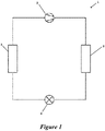
- FIG. 1 is a schematic diagram of a heat transfer circuit 1 of a HVACR system, according to an embodiment.
- the heat transfer circuit 1 includes a compressor 2, a condenser 3, an expansion device 4, and an evaporator 5.
- the heat transfer circuit 1 can be modified to include additional components.
- the heat transfer circuit 1 can include an economizer heat exchanger, one or more flow control devices, a receiver tank, a dryer, a suction-liquid heat exchanger, or the like.
- the components of the heat transfer circuit 1 are fluidly connected.
- the heat transfer circuit 1 can be configured as a cooling system (e.g., a fluid chiller of an HVACR, an air conditioning system, and the like) that can be operated in a cooling mode, and/or the heat transfer circuit 1 can be configured to operate as a heat pump system that can run in a cooling mode and a heating mode.
- a cooling system e.g., a fluid chiller of an HVACR, an air conditioning system, and the like
- the heat transfer circuit 1 can be configured to operate as a heat pump system that can run in a cooling mode and a heating mode.
- the heat transfer circuit 1 as described applies known principles of gas compression and cooling.
- the heat transfer circuit can be configured to heat or cool a process fluid (e.g., water, air).
- a process fluid e.g., water, air
- the heat transfer circuit 1 may represent a chiller that cools a process fluid such as water or the like.
- the heat transfer circuit 1 may represent an air conditioner and/or heat pump that includes a process fluid such as air or the like.
- a working fluid e.g., refrigerant, refrigerant mixture
- a working fluid flows into the compressor 2 from the evaporator 5 at a relatively lower pressure in a gaseous state.
- the compressor 2 compresses the gas into a high pressure state, which also heats the gas.
- the relatively higher pressure and higher temperature gas flows from the compressor 2 to the condenser 3.
- an external fluid e.g., external air, external water, chiller water, and the like
- the external fluid absorbs the heat from the working fluid as it flows through the condenser 3.
- the working fluid condenses to liquid and then flows into the expansion device 4.
- the expansion device 4 reduces the pressure of the working fluid.
- the reduced pressure allows the working fluid to expand and be converted to a mixed vapor and liquid state.
- the relatively lower temperature, vapor/liquid working fluid then flows into the evaporator 5.
- a process fluid e.g., air, water, and the like
- the working fluid absorbs heat from the process fluid as it flows through the evaporator 5.
- the working fluid evaporates to vapor.
- the working fluid then returns to the compressor 2.
- the above-described process continues while the heat transfer circuit 1 is operated, for example, in a cooling mode.
- refrigerant compositions and methods described herein may be used in the heat transfer circuit 1 of the HVACR system. For example, methods of retrofitting a refrigerant composition may be applied to the heat circuit 1 of Figure 1 . Further, refrigerant compositions described herein may be used as a working fluid in the heat circuit of Figure 1 .
- Figure 2 illustrates a matrix 10 that was developed to show plots of GWP, flammability, temperature glide, capacity (relative to R134a), and OEL as a function of the concentration of R1234yf, R134a, and CF 3 I.
- Each side 11, 12, 13 of the triangle corresponds to weight percentages of R1234yf, R134a, or CF 3 I.
- Each vertex 14, 15, 16 corresponds to a composition of 100 wt% R1234yf, R134a, and CF 3 I, respectively.
- compositions for the matrix 10 were estimated using a thermodynamic model. Various properties are described as relative to R134a. R134a and refrigerant compositions were compared based on their properties while used in the simple vapor compression refrigeration cycle. The simple vapor compression refrigerant cycle was operated based under the following conditions:
- FIG. 2 the boundary between flammable and non-flammable compositions is shown in the lower right corner of matrix 10 by a large dashed line. Flammable compositions are on the right side of the boundary and non-flammable compositions are on the left side of the boundary.
- the boundary is based on the known flammability characteristics of R1234yf, R134a, CF 3 I, R513A, and the flame suppressant properties of CF 3 I.
- R513A is a mixture of 56 wt% R1234yf and 44 wt% R134a.
- OEL and GWP are based on the GWP and OEL of the individual components.
- the flammability boundary is estimated based on known characteristics of the individual components and various binary mixtures of the components.
- the amount of each refrigerant in a composition along the flammability boundary may, for example, vary by about 5 percent in an embodiment. It should be appreciated the compositions and ranges shown and/or described may be updated based on further testing to confirm the location of the flammability boundary.
- the OEL of a composition was determined based on the methodology used in ASHRAE Standard 34 for determining OEL of mixtures, which is based on the OEL of the individual refrigerants in the composition.
- OEL n is the OEL of refrigerant n
- M n is the mole fraction of refrigerant n of the total composition.
- M 1 , M 2 , and M 3 are the mole fractions of the first refrigerant, second refrigerant, and third refrigerant, respectively, in the composition.
- OEL 1 , OEL 2 , and OEL 3 are the OELs of the first refrigerant, second refrigerant, and third refrigerant, respectively. Accordingly, it should be appreciated the lines for OELs in Figures 2 - 5 may be revised based on any changes to the OELs of the individual refrigerants.
- Each of Figures 3 - 5 illustrates a matrix 20, 30, 40 that is based on matrix 10 of Figure 2 and has the same sides and vertices as the matrix 10 of Figure 2 .
- Each matrix 20, 30, 40 is the same as the matrix 10 of Figure 2 , except that ranges of refrigerant compositions are illustrated.
- Each matrix 20, 30, 40 can be used in a method of making a refrigerant composition of R1234yf, CF 3 I, and R134a having one or more desired properties.
- an increase in the weight percentage of R134a (shown by side 12) in a composition also increases the GWP of the composition.
- the weight percentage of CF 3 I has the most significant impact on the OEL of the refrigerant composition.
- the capacity of a composition increases as it approaches a mixture 17 of 50 wt% CF 3 I and 50 wt% R134a.
- a desired set of properties of a useful refrigerant composition includes being non-flammable, having a GWP of less than 600, and having a capacity that is not less than 95 wt% of the capacity of R134a. Based on these desired properties, a range of useful refrigerant compositions 21 is shown in the matrix 20 of Figure 3 .
- the useful refrigerant compositions 21 include at or about 85 wt%, or less than 85 wt% and greater than 0 wt% of R1234yf; at or about 46 wt%, or less than 46 wt% and greater than 0 wt% of R134a; and at or about 87.7%, or less than 87.7 wt% and greater than 0 wt% of CF 3 I.
- the useful refrigerant compositions 21 include at or about 85 wt%, or less than 85 wt% and greater than 0 wt% of R1234yf; at or about 46 wt%, or less than 46 wt% and greater than 0 wt% of R134a; and at or about 88 wt%, or less than 88 wt% and greater than 0 wt% of CF 3 I.
- the matrix 20 includes a shaded area 22 and a hatched area 23.
- the shaded area 22 illustrates compositions of the useful compositions 21 that have a temperature glide greater than 1°C.
- the hatched area 23 illustrates compositions of the useful compositions 21 that have a temperature glide of at or about or less than 1°C and greater than 0.5°C.
- the set of desired properties further includes a temperature glide that is at or about or less than 1°C.
- the useful compositions 21 in Figure 3 would not include those compositions within the shaded area 22.
- the set of desired properties further includes a temperature glide that is at or about or less than 0.5°C.
- the useful compositions 21 in Figure 3 would not include those compositions within the shaded area 22 and the hatched area 23.
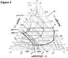
- the useful compositions 20 may include preferred compositions 25 as shown in Figures 3 and 4 .
- the properties of the preferred compositions 25 is that they are non-flammable, have a GWP of less than 600, a temperature glide of 1°C or less, and a capacity that is from 100% to 110% of the capacity of R134a.
- the preferred compositions 25 include from at or about 2 wt% to at or about 68 wt% of R1234yf; from at or about 9.8 wt% to at or about 46 wt% of R134a; and about 63.7 wt%, or less than 63.7 wt% and greater than 0 wt% of CF 3 I.
- the preferred compositions 25 include from at or about 2 wt% to at or about 68 wt% of R1234yf; from at or about 10 wt% to at or about 46 wt% of R134a; and at or about 64 wt%, or less 63.7 wt% and greater than 0 wt% of CF 3 I.
- the desired property of the GWP being less than 600 may be different.
- a composition having a GWP of less than 500 is desired.
- a composition having a GWP of less than 400 is desired.
- composition having a GWP of less than 300 is desired.
- a composition having a GWP of less than 150 is desired.
- the useful compositions 20 in Figure 3 and the preferred compositions 25 in Figures 3 and 4 would include those compositions with the desired GWP.
- the set of desired properties may also include a capacity relative to R134a.
- a composition having a capacity at or about or greater than the capacity of R134a is desired.
- a composition having a capacity at or about or greater than 105% of the capacity of R134a is desired.
- a composition having a capacity from 100% to 110% may be desired.
- a composition having a capacity from 100% to 105% of the capcity of R134a is desired.
- a composition having a capacity from 105% to 110% may be desired.
- the useful compositions 21 shown in Figure 3 and the preferred compositions 25 shown in Figures 3 and 4 would include the compositions that have the desired capacity.
- compositions within the range of preferred compositions 25 may be desired based on the specific properties desired in an embodiment.
- matrix 30 in Figure 4 identifies compositions 25A - 25B of the preferred compositions 25 that have properties that may be desired in a particular embodiment.
- Compositions 25A - 25B are exemplary.
- compositions 25A may be selected as they have capacity that is from 105% to 110% of the capacity of R134a.
- compositions 25A-1, 25A-2, and 25A-3 may be selected in an embodiment as they have a GWP of less than 500 and provide a capacity that is from 105% to 110% of the capacity of R134a.
- compositions 25A-2 and 25A-3 may be selected in an embodiment as they have a GWP of less than 400.
- compositions 25A may be selected as they have a GWP of less than 300.
- compositions 25B may be selected as they have a GWP of 150 or less and a capacity at or about or greater than the capacity of R134a.
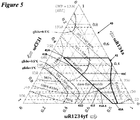
- a desired set of properties of a useful refrigerant composition includes being non-flammable, having a GWP of less than 600, and having an OEL of 400 ppm or greater.
- the matrix 40 of Figure 5 illustrates a range of useful refrigerant compositions 41.
- the useful refrigerant compositions 41 include from at or about 13.5 wt% to at or about 85 wt% of R1234yf; at or about 46 wt%, or less than 46 wt% and greater than 0 wt% of R134a; and at or about 40.5 wt%, or less than 40.5 wt% and greater than 0 wt% of CF 3 I.
- the useful refrigerant compositions 41 include from at or about 14 wt% to at or about 85 wt% of R1234yf; at or about 46 wt%, or less than 46 wt% and greater than 0 wt% of R134a; and at or about 41 wt%, or less than 41 wt% and greater than 0 wt% of CF 3 I.
- the desired property of the GWP being less than 600 may be different.
- a composition having a GWP of less than 500 is desired.
- a composition having a GWP of less than 400 is desired.
- a composition having a GWP of less than 300 is desired.
- a composition that has a GWP of less than 150 is desired.
- the useful compositions 41 in Figure 5 would include those compositions that have the desired GWP.
- the set of desired properties may include a specific capacity.
- a composition having a capacity at or about or greater than the capacity of R134a is desired.
- a composition having a capacity at or about or greater than 105% of the capacity of R134a is desired.
- the useful compositions 41 in Figure 5 would include those compositions that have the desired capacity.
- compositions within the range of useful compositions 25 may be desired based on the specific properties desired in an embodiment.
- matrix 40 in Figure 5 identifies compositions 41A - 41E and 45A of useful compositions 41 that have properties that are desired in a particular embodiment.
- Compositions 41A - 41E and 45A are exemplary.
- compositions 41A, 41B, or 41C may be selected as they have a capacity that is at or about or greater than 105% of the capacity of R134a while also being less than 110% of the capacity of R134a.
- compositions 41B or 41C may be selected as they have a GWP of less than 500 and a capacity that is at or about or greater than 105% of the capacity of R134a.
- compositions 41C may be selected as they have a GWP of less than 400 and a capacity that is at or about or greater than 105% of the capacity of R134a.
- compositions 41D or 41E may be selected as they have a GWP of less than 300 and a capacity that is at or about or greater than the capacity of R134a. In an embodiment, compositions 41E may be selected as they have a GWP of less than 200 and a capacity that is at or about or greater than the capacity of R134a.
- compositions 45A are preferred as they have a GWP of less than 150.
- composition 45A-1 may be selected in an embodiment as it provides the highest capacity.
- Composition 45A-1 is at or about 64 wt% R1234yf, at or about 11.5 wt% R134a, and at or about 24.5 wt% CF 3 I by weight. Table 2 below shows various properties of composition 45A-1.
- Table 2 Properties of Composition 45A-1 Capacity* 99.4% Coefficient of Performance* 97.2% Change in Compressor Discharge Temperature* -12°F Mass Flow Rate* 140% Density (Liquid Phase)* 102% Temperature Glide 0.3°F Compressor Pressure Ratio (Discharge Pressure: Suction Pressure)* 92% * Property is relative to R134a (100% being equivalent to R134a).
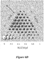
- FIG. 6A - 6D illustrates a matrix of a thermodynamic property for compositions of R1234yf, R134a, and CF 3 I by weight percentage.
- Compositions in each matrix 50, 60, 70, 80 are calculated similarly to the matrixes 10, 20, 30, 40 in Figure 2 - 6 . Accordingly, in Figures 6A - 6D , the axes of R134a are horizontal and parallel to the side for R1234yf, the axes for R1234yf are parallel to the side for CF 3 I, and the axes for CF 3 I are parallel to the side for R134a.
- Each matrix 50, 60, 70, 80 shows values at each 10 wt% of R1234yf, R134a, and CF 3 I (except for 100 wt% R134a in Figures 6A , 6B , and 6D ).
- the values at 100 wt% R134a in Figures 6A , 6B , and 6D are not shown because they are zero.
- composition 51 in Figure 6A corresponds to a composition of 20 wt% R1234yf, 70 wt% R134a, and 10 wt% CF 3 I.
- Figure 6A illustrates a matrix 50 of coefficients of performance (relative to R134a) for compositions of R1234yf, R134a, and CF 3 I.
- Figure 6B illustrates a matrix 60 of compressor discharge temperatures in Fahrenheit (relative to R134a) for compositions of R1234yf, R134a, and CF 3 I.
- Figure 6C illustrates a matrix 70 of mass flow rates (relative to R134a) for compositions of R1234yf, R134a, and CF 3 I.
- Figure 6D illustrates a matrix 80 of operating pressures in PSI (relative to R134a) for compositions of R1234yf, R134a, and CF 3 I.
- Performance of a refrigerant composition may be based on one or more of a coefficient of performance, compressor discharge temperature, mass flow rate, and operating pressure.
- the desired set of properties includes one or more of a coefficient of performance (relative to R134a), compressor discharge temperature (relative to R134a), mass flow rate (relative to R134a), and operating pressure (relative to R134a).
- a composition that has a coefficient of performance of greater than 97% relative to R134a may be preferred.
- a composition that results in a change in the compressor change discharge temperature, relative to R134a, that is at or about or less than 20° F may be preferred.
- a composition that has results in a mass flow rate of less than 1.5 times greater than R134a may be desired. In an embodiment, a composition that has results in a mass flow rate of less than 1.2 times greater than R134a may be desired. In an embodiment, a composition that has results in a mass flow rate of less than 1.1 times greater than R134a may be desired. In an embodiment, a composition that results in an operating pressure of about at or about R134a may be desired. In an embodiment, composition that results in a change in the condenser operating pressure, relative to R134a, of less than less than 20 psid may be desired. In an embodiment, a method of making a refrigerant composition utilizes one or more of the matrices of Figures 2 - 6D so that the refrigerant composition has a desired set of properties.
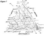
- Figure 7 illustrates a matrix 110 that was developed to show plots of GWP, flammability, temperature glide, capacity (relative to R134a), and OEL as a function of the concentration of R1234ze(E), R134a, and CF 3 I.
- Each side 111, 112, 113 of the triangle corresponds to a percent (by weight) of R1234ze(E), R134a, or CF 3 I.
- Each vertex 14, 15, 16 corresponds to composition of 100 wt% R1234ze(E), R134a, and CF 3 I, respectively.
- Properties e.g., GWP, capacity (relative to R134a), flammability, temperature glide, OEL) of a refrigerant composition with weight percentages of R1234ze(E), R134a, and CF 3 I can be estimated using the matrix 110.
- compositions for the matrix 110 were estimated using a thermodynamic model.
- the boundary between flammable and non-flammable compositions is shown in the lower right corner of matrix 110 by a large dashed line. Flammable compositions are on the right side of the boundary and non-flammable compositions are on the left side of the boundary.
- the boundary is estimated based on known characteristics of R1234ze(E), R134a, CF 3 I, the flammability of R1234ze(E) relative to R1234yf, and the flame suppressant properties of CF 3 I relative to R134a.
- OEL and GWP are based on the GWP and OEL of the individual components.
- the flammability boundary is estimated based on known characteristics of the individual components and various binary mixtures of the individual components.
- the amount of each refrigerant in a composition along the flammability boundary may, for example, vary by about 5 percent in an embodiment. It should be appreciated the compositions and ranges shown and/or described may be updated based on further testing to confirm the location of the flammability boundary.
- the OEL of the compositions in Figure 7 are calculated using the methodology described in ASHRAE 34 in a similar manner as described above. Accordingly, the lines of OELs shown in Figures 7 - 10 may be revised if the OEL of CF 3 I or the refrigerants is changed.
- Each of Figures 8 - 11 illustrates a matrix 120, 130, 140 that is based on matrix 110 of Figure 7 and has the same sides and vertices as the matrix 110 of Figure 7 .
- Each matrix 120, 130, 140 is the same as the matrix 110 of Figure 7 , except that ranges of certain refrigerant compositions are illustrated.
- Each matrix 120, 130, 140 can be used in a method of making a refrigerant composition to make a refrigerant of R1234ze(E), CF 3 I, and R134a with a set of desired properties. As shown in Figure 7 , an increase in the weight percent of R134a (shown by side 112) in a refrigerant composition results in an increase in the composition's GWP.
- weight percentage of CF 3 I in the composition has the most significant impact on the OEL of the composition.
- the capacity of a refrigerant composition increases as it approaches a mixture 117 of approximately 51.5 wt% CF 3 I and 48.5 wt% R134a.
- a mixture of 51.5 wt% CF3I and 48.5 wt% R134a has a coefficient of performance, relative to R134a, of about1.122.
- a desired set of properties of a refrigerant composition includes being non-flammable, having a GWP of less than 600, and having a capacity that is at or about or greater than 90% of the capacity of R134a. Based on these properties, a range of useful refrigerant compositions 121 is shown in matrix 120 of Figure 8 .
- the useful refrigerant compositions 121 include at or about 54.8 wt%, or less than 54.8 wt% and greater than 0 wt% of R1234ze(E); from at or about 1.9 wt% to at or about 46 wt% of R134a; and from at or about 4.5 wt% to at or about 91 wt% of CF 3 I.
- the useful refrigerant compositions 121 include at or about 55 wt%, or less than 55wt% and greater than 0 wt% of R1234ze(E); from at or about 2 wt% to at or about 46 wt% of R134a, and from at or about 5 wt% to at or about 91 wt% of CF 3 I
- the desired property of the GWP being less than 600 may be different.
- a composition having a GWP of less than 500 is desired.
- a composition having a GWP of less than 400 is desired.
- a composition having a GWP of less than 300 is desired.
- a composition having a GWP of less than 150 is desired.
- the useful compositions 121 shown in Figure 8 and preferred compositions 125 shown in Figures 8 and 9 would include those compositions that have the desired GWP.
- the desired property of the capacity being at or about or less than 90% of the capacity of R134a may be different.
- a composition having a capacity at or about or greater than 90% of the capacity of R134a is desired.
- a composition having a capacity at or about or greater than 95% of the capacity of R134a is desired.
- a composition having a capacity at or about or greater than the capacity of R134a is desired.
- the useful compositions 121 shown in Figure 8 and the preferred compositions 125 shown in Figures 8 and 9 would include those compositions that have the desired capacity.
- the matrix 120 includes shaded area 122, 123.
- the shaded areas 122, 123 illustrate compositions of the useful compositions 121 that have a temperature glide of greater than 1°C.
- the set of desired properties includes a temperature glide that is at or about or less than 1°C.
- the useful compositions 121 may include preferred compositions 125 as shown in Figures 8 and 9 .
- the properties of the preferred compositions 125 is that they are non-flammable, have a GWP of less than 600, a temperature glide of 1°C or less, and a capacity that is at least 90% of the capacity of R134a.
- the preferred refrigerant compositions 125 include at or about or less than 52.6 wt% and greater than 0 wt% of R1234ze(E), from 1.9 wt% to 46 wt% of R134a, and from 25.2 wt% to 76.2 wt% of CF 3 I. As similarly discussed previously, these ranges may be updated if further testing determines that the OEL of CF 3 I is revised to be greater. For example, maximum amount in the range of CF 3 I may be greater if the OEL is determined to be larger value than 150 ppm.
- compositions within the range of the preferred compositions 125 may have specific properties that are desired in a particular embodiment.
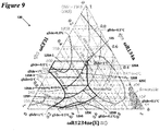
- matrix 130 in Figure 9 identifies compositions 125A - 125G of the preferred compositions 125 that have properties that may be desired in a particular embodiment.
- Compositions 125A - 125G are exemplary compositions.
- compositions 125A, 125B, 125C and 125D-1 may be selected as they have a capacity that is at or about or greater than the capacity of R134a.
- compositions 125A-1 may be selected in an embodiment as they have a temperature glide that is at or about or less than 0.5°C.
- compositions 125B, 125C, and 125D-1 may be selected as they have GWP of less than 500 and a capacity that is at or about or greater than the capacity of R134a.
- compositions 125B-1 may be selected in an embodiment as they have a temperature glide that is at or about or less than 0.5°C.
- compositions 125C and 125D-1 may be selected as they have a GWP of less than 400 and a capacity at or about or greater than the capacity of R134a.
- compositions 125D may be selected as they have a GWP of less than 300 and a capacity that is at or about or greater than 95% of the capacity of R134a.
- compositions 125D-1 may be selected in an embodiment as they have a capacity that is at or about or greater than the capacity of R134a.
- compositions 125E may be selected as they have a GWP of less than 200 and a capacity that is at or about or greater than 95% of the capacity of R134a.
- compositions 125F may be selected as they have a GWP of less than 150 and a capacity that is at or about or greater than 95% of the capacity of R134a.
- compositions 125G may be selected as they have GWP of less than 150 and a temperature glide that is at or about or less than 0.5°C.
- a desired set of properties of a useful refrigerant composition includes being non-flammable, having a GWP of less than 600, and having an OEL of 400 ppm or greater. Based on these desired properties, a range of useful refrigerant compositions 141 of R1234ze(E), R134a, and CF 3 I is shown in the matrix 140 of Figure 10 .
- the useful refrigerant compositions 141 include from at or about 10 wt% to at or about 90 wt% of R1234ze(E); at or about 46 wt%, or less than 46 wt% and greater than 0 wt% of R134a; and at or about 43.5 wt%, or less than 43.5 wt% and greater than 0 wt% of CF 3 I.
- the useful refrigerant compositions 141 may include from at or about 10 wt% to at or about 90 wt% of R1234ze(E); at or about 46 wt%, or less than 46 wt% and greater than 0 wt% of R134a; and at or about 44 wt%, or less than 44 wt% and greater than 0 wt% of CF 3 I.
- the lines for OEL may be revised upon a determination that the OEL of CF 3 I is greater than described. It should be appreciated that the ranges shown and/or described may be similarly revised. For example, maximum amount in the range of CF 3 I may be greater if the OEL is determined to be larger value than 165 ppm.
- the desired property of the GWP being less than 600 may be different.
- a composition having a GWP of less than 500 is desired.
- a composition having a GWP of less than 400 is desired.
- a composition having a GWP of less than 300 is desired.
- a composition having a GWP of less than 150 is desired.
- the useful compositions 141 in Figure 10 would include those compositions that have the desired GWP.
- set of desired properties may include a specific capacity.
- a composition having a capacity at or about or greater than 90% of the capacity of R134a is desired.
- a composition having a capacity at or about or greater than 95% of the capacity of R134a is desired.
- a composition having a capacity at or about or greater than the capacity of R134a is desired.
- the useful compositions 141 in Figure 10 would include those compositions that have the desired capacity.
- Figure 10 includes shaded area 142.
- the shaded area 142 shows those compositions of the useful compositions 141 that have a temperature glide of greater than 1°C.
- a composition having a temperature glide of 1°C or less may be desired.
- useful compositions 141 shown in Figure 10 may not include those compositions that have a temperature glide greater than 1°C. Accordingly, in such embodiments, each of compositions 141C, 141E, and 145 shown in Figure 10 would be modified to not include any composition in the shaded area 142.
- compositions within the range of useful compositions 141 in Figure 10 may be desired based on the specific properties desired in an embodiment.
- matrix 140 of Figure 10 identifies ranges of compositions 141A - 141E and 145A that may be desired in an embodiment.
- Compositions 141A - 141G and 145A are exemplary.
- compositions 141A and 141B may be selected as they have a capacity that is at or about or greater than 100% of the capacity of R134a. In an embodiment, compositions 141B may be selected as they have a GWP of less than 500 and a capacity that is at or about or greater than 100% of the capacity of R134a. In an embodiment, compositions 141C and 141 D may be selected as they have a GWP of less than 400 and a capacity that is at or about or greater than 95% of the capacity of R134a. In an embodiment, compositions 141D may be selected as they have a GWP that is less than 300 and a capacity that is at or about or greater than the 90% of the capacity of R134a. In an embodiment, compositions 141E may be selected as they have a GWP of less than 200 and a capacity that is at or about or greater than 90% of the capacity of R134a.
- compositions 145A of useful compositions 141 are preferred as they have a GWP of less than 150.
- the compositions 145 include from at or about 49.5 wt% to at or about 90 wt% of R1234ze(E); at or about 11.5 wt%, or less than 11.5 wt% and greater than 0 wt% of R134a; and from at or about 6.6 wt% to at or about 39 wt% of CF 3 I.
- compositions 145 may include at or about 49 wt% to at or about 90 wt% of R1234ze(E); at or about 11 wt%, or less than 11 wt% and greater than 0 wt% of R134a; and from at or about 6 wt% to at or about 39 wt% of CF 3 I.
- compositions 145A may be selected as they have a capacity that is at or about or greater than 90% of the capacity of R134a.
- composition 145A-1 may be selected in an embodiment as it provides the greater capacity.
- Composition 145A-1 is at or about 49.5 wt% of 1234ze(E), at or about 11.5 wt% of R134a, and at or about 39 wt% of CF 3 I. Table 3 below shows various properties of composition 145A-1.
- Table 3 Properties of Composition 145A-1 Capacity* 90.5% Coefficient of Performance* 99.3% Change in Compressor Discharge Temperature* -5°F Mass Flow Rate* 136% Density (Liquid)* 1.14% Temperature Glide 0.9°F Compressor Pressure Ratio (Discharge Pressure: Suction Pressure)* 97% * Property is relative to R134a (100% being equal to R134a).
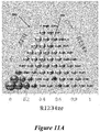
- FIG. 11A - 11D illustrates a matrix 150, 160, 170, 180 of a thermodynamic property for compositions of R1234ze(E), R134a, and CF 3 I.
- Compositions in each matrix 150, 160, 170, 180 are calculated similarly to each matrix 110, 120, 130, 140 in Figures 7 - 10 . Accordingly, the axes for R134a are horizontal and parallel to the side for R1234ze(E), the axes for R1234ze(E) are parallel to the side for CF 3 I, and the axes for CF 3 I are parallel to the side for R134a.
- Each matrix 150, 160, 170, 180 shows a value for its respective thermodynamic property at 10 wt% increments of R1234yf, R134a, and CF 3 I (except for 100 wt% R134a in Figures 11A , 11B , and 11D ).
- a value for 100 wt% R134a in Figures 11A , 11B , and 11D is not shown as the value is zero.
- composition 151 in Figure 11A is 20 wt% R1234ze(E), 70 wt% R134a, and 10 wt% CF 3 I.
- Figure 11A illustrates a matrix 150 of coefficients of performance (relative to R134a) for compositions of R1234ze(E), R134a, and CF 3 I.
- Figure 11B illustrates a matrix 160 of compressor discharge temperatures in Fahrenheit (relative to R134a) for compositions of R1234ze(E), R134a, and CF 3 I.
- Figure 11C illustrates a matrix 170 of mass flow rates (relative to R134a) for compositions of R1234ze(E), R134a, and CF 3 I.
- Figure 11D illustrates a matrix 180 of operating pressures in PSI (relative to R134a) for compositions of R1234ze(E), R134a, and CF 3 I.
- Performance of a refrigerant composition may be based on a coefficient of performance, compressor discharge temperature, mass flow rate, and/or operating pressure.
- a composition having a specific coefficient of performance (relative to R134a), compressor discharge temperature (relative to R134a), mass flow rate (relative to R134a), and/or operating pressure (relative to R134a) may be desired.
- a composition that has a coefficient of performance of greater than 97% relative to R134a may be preferred.
- a composition that results in a change in the compressor change discharge temperature, relative to R134a, that is at or about or less than 20° F may be preferred.
- a composition that has results in a mass flow rate of less than 1.5 times greater than R134a may be desired. In an embodiment, a composition that has results in a mass flow rate of less than 1.2 times greater than R134a may be desired. In an embodiment, a composition that has results in a mass flow rate of less than 1.1 times greater than R134a may be desired. In an embodiment, a composition that results in an operating pressure of about at or about the operating pressure of R134a may be desired. In an embodiment, composition that results in a change in the condenser operating pressure, relative to R134a, of less than less than 20 psid may be desired. In an embodiment, a method of making a refrigerant composition utilizes one or more of the matrices of Figures 7 - 11D so that the refrigerant composition has a desired set of properties.
- Figure 12 illustrates a matrix 210 that was developed to show plots of GWP, flammability, temperature glide, capacity (relative to R134a), and OEL as a function of the concentration of R152a, R134a, and CF 3 I.
- Each side 211, 212, 213 of the triangle corresponds to percentages (by weight) of R134a, R152a, or CF 3 I.
- Each vertex 214, 215, 216 corresponds to composition of 100 wt% R152a, CF 3 I, and R134a, respectively.
- Properties e.g., GWP, capacity relative to R134a, flammability, temperature glide, OEL
- GWP capacity relative to R134a
- OEL temperature glide
- compositions for the matrix 210 were estimated using a thermodynamic model.
- the boundary between flammable and non-flammable compositions is shown matrix 210 by the large dashed line. Flammable compositions are on the right side of the boundary and non-flammable compositions are on the left side of the boundary.
- the boundary is estimated based on the flammability characteristics of R152a, R134a, and CF 3 I; the known flammability boundary of binary mixtures of R152a and R134a; the flammability of R152a relative to R1234yf; and the flame suppressant properties of CF 3 I.
- OEL and GWP are based on the GWP and OEL of the individual components.
- the flammability boundary is estimated based on known characteristics of the individual components and binary mixtures of the individual components. Accordingly, the amount of each refrigerant in a composition along the flammability boundary may, for example, vary by about 5 percent in an embodiment. It should be appreciated the compositions and ranges shown and/or described may be updated based on further testing to confirm the location of the flammability boundary.
- the OEL of the compositions in Figure 12 are calculated using the methodology described in ASHRAE 34, in a similar manner as described above regarding Figure 1 . Accordingly, the lines of OELs shown in Figures 12 - 15 may be revised based on any changes to the OELs of the refrigerants.
- Each of Figures 13 - 15 illustrates a matrix 220, 230, 240 that is based on the matrix 210 of Figure 12 and has the same sides and vertices as matrix 210.
- Each matrix 220, 230, 240 is the same as the matrix 210 of Figure 12 , except that ranges of refrigerant compositions are illustrated.
- an increase in the weight percent of R134a (shown by side 211) in a composition also increases the GWP of the composition.
- weight percentage of CF 3 I in the composition has the largest impact on the composition's OEL of the composition.
- the capacity of a composition increases as it approaches a mixture 217 of at or about 51.5 wt% CF 3 I and at or about 48.5 wt% R134a.
- a desired set of properties of a useful refrigerant composition includes being non-flammable and having a GWP of less than 600. Based on these desired properties, a range of useful refrigerant compositions 221 of R152a,
- R134a, and CF 3 I is shown in the matrix 220 of Figure 13 .
- the useful refrigerant compositions 221 include at or about 30 wt%, or less than 30 wt% and greater than 0 wt% of R152a; at or about 46 wt%, or less than 46 wt% and greater than 0% of R134a; and at or about 33.9 wt%, or greater than 33.9 wt% and less than 100 wt% of CF 3 I.
- the useful composition 221 may include at or about 30 wt%, or less than 30 wt% and greater than 0 wt% of R152a; at or about 46 wt%, or less than 46 wt% and greater than 0% of R134a; and at or about 34 wt%, or greater than 34 wt% and less than 100 wt% of CF 3 I.
- Figure 13 includes a shaded area 222 and hatched areas 223, 224.
- the shaded area illustrates compositions of the useful compositions 221 that have a temperature glide that is greater than 1°C.
- the hatched areas 223, 224 illustrate compositions of the useful compositions 221 that have a temperature glide that is at or about or less than 1.0°C and greater than 0.5°C.
- the set of desired properties includes a temperature glide that is at or about or less than 1°C.
- the useful compositions 221 in Figure 13 would include those compositions that are not within the shaded area 222.
- the set of desired properties includes a temperature glide that is at or about or less than 0.5°C.
- the useful compositions 221 in Figure 13 would include those compositions that are not within the shaded area 222 or the hatched areas 223, 224.
- useful compositions 220 may include preferred compositions 225 as shown in Figures 13 and 14 .
- the preferred compositions 225 are non-flammable, have a GWP of less than 600, a capacity at or about or less than 110% of the capacity of R134a, and a temperature glide of 1°C or less.
- the preferred refrigerant compositions 225 include from at or about1 wt% to at or about 30 wt% of R152a; at or about 46 wt%, or less than 46 wt% and greater than 0 wt% of R134a, and from at or about 33.9 wt% to at or about 78.6 wt% of CF 3 I.
- the preferred refrigerant compositions 225 include from at or about 1 wt% to at or about 30 wt% of R152a; at or about 46 wt%, or less than 46 wt% and greater than 0 wt% of R134a, and from at or about 34 wt% to at or about 79 wt% of CF 3 I.
- a desired property of the GWP being less than 600 may be different.
- a composition having a GWP of less than 500 is desired.
- a composition having a GWP of less than 400 is desired.
- a composition having GWP of less than 300 is desired.
- a composition having a GWP of less than 150 is desired.
- the useful compositions 221 shown in Figure 13 and preferred compositions 225 shown in Figures 13 and 14 would include those compositions that have the desired GWP.
- the set of desired properties may include a capacity relative to R134a.
- a composition having a capacity at or about or greater than the capacity of R134a is desired.
- a composition having a capacity at or about or greater than 105% of the capacity of R134a is desired.
- a composition having a capacity that is from 100% to 110% of the capacity of R134a is desired.
- a composition having a capacity that is from 100% to 105% is desired.
- a composition having a capacity that is from 105% to 110% of the capacity of R134a is desired.
- the useful compositions 221 shown in Figure 13 and the preferred compositions 225 shown in Figures 13 and 14 would include those compositions that have the desired capacity.
- compositions within the range of preferred compositions 225 may be desired based on the specific properties desired in an embodiment.
- matrix 230 in Figure 14 identifies compositions 225A - 225B of preferred composition 225 that have properties that may be desired in a particular embodiment.
- Compositions 225A - 225B are exemplary.
- compositions 225A may be selected as they have a GWP of less than 200 and a capacity that is at or about or greater than the 105% of the capacity of R134a.
- compositions 225B may be selected as they a GWP of less than 150.
- compositions 225B-1 may be selected in an embodiment as they have a capacity that is at or about or greater than 105% of the capacity of R134a.
- Figure 14 includes hatched areas 224, 233.
- the hatched areas 224, 233 illustrate compositions of the preferred compositions 225 that have a temperature glide greater than 0.5°C.
- a desired set of properties includes a temperature glide at or about or less than 0.5°C.
- the preferred compositions 225 shown in Figure 14 would not include those compositions within the hatched areas 224, 233. Accordingly, in such embodiments, the compositions 225A - 225D shown in Figure 14 would include those compositions that are not within the hatched area 233.
- a desired set of properties of a refrigerant composition includes being non-flammable, having a GWP of less than 600, and having an OEL of 300 ppm or greater.
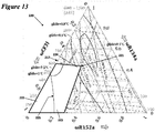
- the matrix 240 of Figure 15 shows a range of useful refrigerant compositions 241 of R152a, R134a, and CF 3 I.
- the useful refrigerant compositions 241 include from at or about 2 wt% to at or about 30 wt% R152a; at or about 46 wt%, or less than 46 wt% and greater than 0 wt% of R134a, and from at or about 33.9 wt% to at or about 74.2 wt% of CF 3 I.
- the useful refrigerant compositions may include at or about 2 wt% to at or about 30 wt% R152a; at or about 46 wt%, or less than 46 wt% and greater than 0 wt% of R134a, and from at or about 34 wt% to at or about 75 wt% of CF 3 I.
- the lines for OEL may be revised upon a determination that the OEL of CF 3 I is greater than described. It should be appreciated that the ranges shown and/or described may be similarly revised. For example, maximum amount in the range of CF 3 I may be greater if the OEL is determined to be larger value than 165 ppm.
- the desired property of the GWP being less than 600 may be different.
- a composition having a GWP of less than 500 is desired.
- a composition having a GWP of less than 400 is desired.
- a composition having a GWP of less than 300 is desired.
- a composition having a GWP of less than 150 is desired.
- the useful compositions 241 in Figure 15 would include those compositions that have the desired GWP.
- the set of desired properties may include a capacity relative to R134a.
- a composition having a capacity at or about or greater than the 105% of the capacity of R134a may be desired.
- a composition having a capacity from 100% to 110% of the capacity of R134a may be desired.
- a composition having a capacity that is from 100% to 105% of the capacity of R134a may be desired.
- a composition having a capacity that is from 105% to 110% of the capacity of R134a may be desired.
- the useful compositions 241 in Figure 15 would include those compositions that have the desired capacity.
- compositions within the range of useful compositions 241 of matrix 240 may be desired based on the specific properties desired in an embodiment.
- matrix 240 of Figure 15 identifies ranges of compositions 241A - 241C and 245 that have properties that may be desired in a particular embodiment.
- Compositions 241A - 241C and 245 are exemplary.
- compositions 241A, 241B, and 241C may be selected as they have an OEL that is at or about or greater than 400 ppm. In an embodiment, compositions 241B and 241C may be selected as they have an OEL at or about or greater than 400 ppm and a GWP less than 500. In an embodiment, compositions 241C may be selected as they have an OEL of 400ppm or greater and a GWP of less than 400. Compositions 241A, 241B, and 241C would be ASHRAE class A refrigerants as they have an OEL of 400 ppm or greater.
- compositions 245 of useful compositions 241 may be preferred as they have a GWP of less than 150.
- Compositions 245 include from at or about 21.5 wt% to at or about 30 wt% of R152a; at or about 49 wt%, or less than 49 wt% and greater than 0 wt% of R134a; and from at or about 63.4 wt% to at or about 78.6 wt% of CF 3 I.
- compositions 245 may include from at or about 21 wt% to at or about 30 wt% of R152a; at or about 49 wt%, or less than 49 wt% and greater than 0 wt% of R134a; and from at or about 63 wt% to at or about 79 wt% of CF 3 I.
- compositions 245A may be selected in an embodiment as they have a capacity that is at least 105% of the capacity of R134a.
- composition 245A-1 may be selected in an embodiment as it provides the greatest capacity.
- Composition 245A-1 is at or about 21.5 wt% R152a, at or about 9 wt% R134a, and at or about 69.5 wt% CF 3 I by weight. Table 4 below shows various properties of composition 245A-1. Table 4: Properties of Composition 245A-1 Capacity* 105% Coefficient of Performance* 101% Change in Compressor Discharge Temperature* +12°F Mass Flow Rate* 134% Density (Liquid)* 123% Temperature Glide 0.8°F Compressor Pressure Ratio (Discharge Pressure: Suction Pressure)* 92% * Property is relative to R134a (100% being equal to R134a).
- Figure 15 includes hatched areas 242, 243.
- the hatched areas 242, 243 illustrate compositions of the useful compositions 241 that have a temperature glide that is greater than 0.5°C.
- the set of desired properties includes a temperature glide of 0.5°C or less.
- the useful compositions 241 shown in Figure 15 would include those compositions that are not within the hatched areas 242, 243.
- compositions 241A would include those compositions that are not within the hatched area 243.
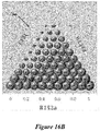
- FIG. 16A - 16D illustrates a matrix 250, 260, 270, 280 of a thermodynamic property for compositions of R152a, R134a, and CF 3 I.
- Compositions in each matrix 250, 260, 270, 280 are calculated similarly to the matrixes 210, 220, 230, 240 in Figure 12 - 15 .
- the axes for R134a are parallel axis to the side for R152a (e.g., horizontal)
- the axes for R152a are parallel to the side for CF 3 I
- the axes for CF 3 I are parallel to axis of side for R134a.
- Each matrix 250, 260, 270, 280 shows values of compositions at each 10 wt% increments of R152a, R134a, and CF 3 I (except for 100 wt% R134a in Figures 16A , 16B , and 16D ).
- the values for 100 wt% R134a in Figure 16A , 16B , and 16D are not shown as they have values of at or about zero.
- composition 251 in Figure 16A corresponds to a composition of 20 wt% R152a, 70 wt% R134a, and 10 wt% CF 3 I.
- Figure 16A illustrates a matrix 250 of coefficients of performance (relative to R134a) for compositions of R152a, R134a, and CF 3 I.
- Figure 16B illustrates a matrix 260 of compressor discharge temperatures in Fahrenheit (relative to R134a) for compositions of R152a, R134a, and CF 3 I.
- Figure 16C illustrates a matrix 270 of mass flow rates (relative to R134a) for compositions of R152a, R134a, and CF 3 I.
- Figure 16D illustrates a matrix 280 of operating pressures in PSI (relative to R134a) for compositions of R152a, R134a, and CF 3 I.
- Performance of a refrigerant composition may be based on one or more of a coefficient of performance, compressor discharge temperature, mass flow rate, and operating pressure.
- a composition having a specific coefficient of performance (relative to R134a), compressor discharge temperature (relative to R134a), mass flow rate (relative to R134a), and/or operating pressure (relative to R134a) may be desired.
- a composition that has a coefficient of performance of greater than 97% relative to R134a may be preferred.
- a composition that results in a change in the compressor change discharge temperature, relative to R134a, that is at or about or less than 20° F may be preferred.
- a composition that has results in a mass flow rate of less than 1.5 times greater than R134a may be desired. In an embodiment, a composition that has results in a mass flow rate of less than 1.2 times greater than R134a may be desired. In an embodiment, a composition that has results in a mass flow rate of less than 1.1 times greater than R134a may be desired. In an embodiment, a composition that results in an operating pressure of about at or about R134a may be desired. In an embodiment, composition that results in a change in the condenser operating pressure, relative to R134a, of less than less than 20 psid may be desired. In an embodiment, a method of making a refrigerant composition utilizes one or more of the matrices of Figures 12 - 15D so that the refrigerant composition has a desired set of properties.
- the described refrigerant compositions may include one or more additional components.
- additional components may be impurities, lubricant, and refrigeration system additives, tracers, and an ultraviolet ("UV") dye and solubilizing agent.
- UV ultraviolet
- a refrigerant composition may include less than 1 wt% of these additional components.
- Some refrigerant compositions, depending upon their components, may have less than about 5 wt% of some additives, such as lubricants, in a particular location or piece of equipment in a heat transfer circuit.
- the refrigerant compositions described would have the ranges described above and the additive would be added in addition to the composition.
- a refrigerant composition may include one or more impurities.
- An impurity may be, for example, a refrigerant or refrigerant blend used in an HVACR system.
- An impurity may be, for example, refrigeration lubricants, particulates (e.g., metal particles, metal salts, elastomer particles) from equipment of the HVACR system, and other contaminant that may adversely affect a working fluid.
- a refrigerant composition may include one or more lubricants that are compatible with the refrigerant composition.
- a lubricant may be a lubricant that is designed for use with HFCs and HFOs and is compatible with refrigerant compositions described herein.
- the lubricant may be based on the HVACR system that will be using the refrigerant composition.
- a lubricant may be selected based on the equipment of the HVACR system (e.g., compressor 2 in Figure 1 ) and the environment in which the refrigerant may be exposed to.
- a refrigerant composition may include those lubricants known as "mineral oils” and/or those lubricants known as "synthetic oils” in the field of compression refrigeration lubrication.
- a refrigerant composition may include one or more refrigeration system additives to, for example, enhance lubricity and/or system stability.
- a refrigeration system additive may be, for example, an anti-wear agent, an extreme pressure lubricant, a corrosion or oxidation inhibitor, a metal surface deactivator, a stabilizer (e.g., antioxidant, free radial scavenger, water scavenger), a foaming and antifoam control agent, or a leak detectant.
- a refrigerant composition may include one or more tracers.
- the tracers may be used in detecting if any dilution, contamination, or other alteration of the working fluid (which includes the refrigerant composition) has occurred.
- a refrigerant composition may include one or more UV dyes.
- the UV dye may allow a person (e.g., operator, field technician) to observe leaks in or near the HVACR system. Due to the low solubility of some UV dyes in some refrigerant compositions, a solubilizing agent may be included with the UV dye.
- a refrigerant composition in a HVACR system may be retrofitted.
- the refrigerant composition is retrofitted to have a desired set of properties.
- the refrigerant composition is retrofitted so as to result in a retrofitted refrigerant composition that includes a first refrigerant, a second refrigerant, and a third refrigerant.
- the first refrigerant is R134a
- the second refrigerant is CF 3 I
- the third refrigerant is either R152a, R1234yf, or R1234ze(E).
- the refrigerant composition to be retrofitted in an embodiment may include R134a; a mixture of R152a and CF 3 I; or a mixture of a HFO (R1234yf or R1234ze(E)) and CF 3 I.
- an HVACR utilizes a refrigerant composition including R134a
- a method of retrofitting the refrigerant composition of the HVACR includes adding an amount of a low GWP HFC or a HFO and adding an amount of a CF 3 I.
- the amount of low GWP HFC or HFO added and the amount of CF 3 I added are amounts that result in a retrofitted refrigerant composition with the desired set of properties.
- retrofitted compositions with the desired set of properties can be determined using the matrices in Figures 2 - 6D .
- retrofitted compositions that would have the desired set of properties can be determined using the matrices in Figures 7 - 11D .
- retrofitted compositions that would have the desired set of properties can be determined using the matrices in Figures 12 - 16D .
- an HVACR utilizes a refrigerant composition that is a mixture of a low GWP HFC and CF 3 I or a mixture of a HFO and CF 3 I, and a method of retrofitting the refrigerant composition of the HVACR includes adding an amount of R134a.
- the amount of R134a added is an amount that results in a retrofitted refrigerant composition that has the desired properties.
- retrofitted compositions that have the desired set of properties can be determined using the matrices in Figures 2 - 6D .
- retrofitted compositions that would have the desired set of properties can be determined using the matrices in Figures 7 - 11D .
- the retrofitted composition that would have the desired set of properties can be determined using the matrices in Figures 12 - 16D .
- a method for making a refrigerant composition for a HVACR system includes selecting an amount of a first refrigerant, selecting an amount of CF 3 I, selecting an amount of R134a, and mixing the amounts of the first refrigerant, the CF 3 I, and the R134a.
- the amounts of the first refrigerant, the CF 3 I, and the R134a may be selected so that the refrigerant composition has one or more desired properties.
- a desired property may be, for example, flammability, GWP, OEL, temperature glide, a coefficient of performance, compressor discharge temperature, mass flow rate, or operating pressure.
- the first refrigerant is either a low GWP HFC or a HFO.
- the HFO is R1234yf.
- one or more matrixes in Figures 2 - 6D are utilized so that the refrigerant composition has the one or more desired properties.
- the low GWP HFC is R152a.
- one or more matrixes in Figures 12 - 16D are utilized so that the refrigerant composition has the one or more desired properties.
- the HFO is R1234ze(E).
- one or more matrixes in Figures 7 - 11D are utilized so that the refrigerant composition has the one or more desired properties.
- the method may include selecting an appropriate amount of one or more additional components (e.g., lubricant, and refrigeration system additives, tracers, an ultraviolet dye, a solubilizing agent).
- additional components e.g., lubricant, and refrigeration system additives, tracers, an ultraviolet dye, a solubilizing agent.
- the amount of the first refrigerant is selected so that the refrigerant composition has a GWP of less than 600. In an embodiment, the amount of CF 3 I is selected so that the refrigerant composition is non-flammable. As CF 3 I has a low GWP, selecting the amount of the first refrigerant may also consider the amount of the CF 3 I selected in an embodiment.
- the amount of the R134a is selected to address the capacity of the refrigerant composition in an embodiment.
- any of aspects 1 - 13 can be combined with any of aspects 14 -26 and any of aspects 14 - 17 can be combined with any of aspects 18 - 26.
Landscapes
- Chemical & Material Sciences (AREA)
- Engineering & Computer Science (AREA)
- Physics & Mathematics (AREA)
- Thermal Sciences (AREA)
- Chemical Kinetics & Catalysis (AREA)
- Combustion & Propulsion (AREA)
- Materials Engineering (AREA)
- Organic Chemistry (AREA)
- Mechanical Engineering (AREA)
- General Engineering & Computer Science (AREA)
- Lubricants (AREA)
Abstract
Description
- The disclosure herein relates to refrigerant compositions, which can be used in, for example, refrigeration, air conditioning, and/or heat pump systems, which, for example, can be incorporated into a heating, ventilation, air conditioning, and refrigeration (HVACR) system or unit.
- Concern about environmental impact (e.g., ozone depletion) and the approval of the Montreal Protocol have resulted in a movement to replace ozone depleting refrigerants such as chlorofluorocarbons (CFCs) and hydrochlorofluorocarbons (HCFCs). Refrigerants, such as hydrofluorocarbons (HFCs) refrigerants and hydrofluoroolefins (HFOs) refrigerants have been utilized as replacements for previous refrigerants containing CFCs and HFCs. However, there has been recent movement (e.g., the Kigali Amendment to the Montreal Protocol, the Paris Agreement, United States' Significant New Alternatives Policy ("SNAP")) to phase out refrigerants that have a high global warming potential (GWP) such as some HFCs.
- Refrigerant compositions that are non-flammable and have an increased capacity and methods of making such compositions are described. Refrigerant compositions that perform similar to R134a are described. Refrigerant compositions, methods of making refrigerant compositions, and methods of retrofitting refrigerant compositions for servicing, controlling flammability, decreasing GWP, improving performance, and/or improving safety of an HVACR system are described.
- In an embodiment, a refrigerant composition is non-flammable and includes a first refrigerant, a second refrigerant, and a third refrigerant. In an embodiment, the first refrigerant is R152a refrigerant, R1234yf refrigerant, or R1234ze(E) refrigerant. In an embodiment, the second refrigerant is R134a refrigerant. In an embodiment, the third refrigerant is CF3I. In an embodiment, the refrigerant composition has a GWP of less than 600.
- In an embodiment, the amounts of the first refrigerant, second refrigerant, and third refrigerant are selected so that the GWP of the refrigerant composition is less than 150.
- In an embodiment, the refrigerant composition has a temperature glide that is at or about or less than 1.0°C.
- In an embodiment, the refrigerant composition has an occupational exposure limit (OEL) of 300 parts per million (ppm) or greater. In an embodiment, the refrigerant composition has an OEL of 400ppm or greater.
- In an embodiment, a capacity of the refrigerant composition is at or about or within 10% of a capacity of R134a refrigerant.
- In an embodiment, a method of making the refrigerant composition includes mixing an amount of a first refrigerant, an amount of a second refrigerant, and an amount of a third refrigerant. The first refrigerant being R134a refrigerant, the second refrigerant being CF3I, and the third refrigerant being either R152a refrigerant, R1234yf refrigerant, or R1234ze(E) refrigerant. The refrigerant composition is nonflammable. The amounts of the first refrigerant, second refrigerant, and third refrigerant are selected so that the GWP of the refrigerant composition is less than 600.
- In an embodiment, the amounts of the first refrigerant, second refrigerant, and third refrigerant are selected so that the GWP of the refrigerant composition is less than 150.
- In an embodiment, the refrigerant composition has a temperature glide that is at or about or less than 1.0°C.
- In an embodiment, the refrigerant composition has an occupational exposure limit (OEL) of 300 parts per million (ppm) or greater. In an embodiment, the refrigerant composition has an OEL of 400ppm or greater.
- In an embodiment, a capacity of the refrigerant composition is at or about or within 10% of a capacity of R134a refrigerant.
- In an embodiment, a method of retrofitting a refrigerant composition in an HVACR system results in a retrofitted refrigerant composition that is the refrigerant composition including the first refrigerant, the second refrigerant, and the third refrigerant. In an embodiment, the method includes adding the second refrigerant and the third refrigerant to the first refrigerant. In an embodiment, the method includes adding the first refrigerant to the second and third refrigerants. The first refrigerant is R134a refrigerant, the second refrigerant is CF3I, and the third refrigerant is either R152a refrigerant, R1234yf refrigerant, or R1234ze(E) refrigerant. The retrofitted refrigerant composition is nonflammable. The amounts of the first refrigerant, second refrigerant, and the third refrigerant are such that the resulting retrofitted refrigerant composition has a GWP of less than 600.
- In an embodiment, the amounts of the first refrigerant, second refrigerant, and third refrigerant are selected so that the GWP of the refrigerant composition is less than 150.
- In an embodiment, the refrigerant composition has a temperature glide that is at or about or less than 1.0°C.
- In an embodiment, the refrigerant composition has an occupational exposure limit (OEL) of 300 parts per million (ppm) or greater. In an embodiment, the refrigerant composition has an OEL of 400ppm or greater.
- In an embodiment, a capacity of the refrigerant composition is at or about or within 10% of a capacity of R134a refrigerant.
- Both described and other features, aspects, and advantages of refrigerant composition, methods of making, and methods of retrofitting a refrigerant composition in an HVACR will be better understood with reference to the following drawings:
-
Figure 1 illustrates a heat transfer circuit of a HVACR system in an embodiment. -
Figure 2 illustrates a matrix of compositions of R1234yf, R134a, and CF3I showing plots of GWP, flammability, temperature glide, capacity (relative to R134a), and OEL. -
Figures 3 - 5 each illustrate a matrix based on the matrix ofFigure 2 that can be used to select a refrigerant composition with a desired set of properties in an embodiment. -
Figures 6A - 6D each illustrate a matrix of a thermodynamic property of compositions of R1234yf, R134a, and CF3I. -
Figure 7 illustrates a matrix of compositions of R1234ze(E), R134a, and CF3I showing plots of GWP, flammability, temperature glide, capacity (relative to R134a), and OEL. -
Figures 8 - 10 each illustrate a matrix based on the matrix ofFigure 7 that can be used to select a refrigerant composition with a desired set of properties in an embodiment. -
Figures 11A - 11D each illustrate a matrix of a thermodynamic property of compositions of R1234ze(E), R134a, and CF3I. -
Figure 12 illustrates a matrix of compositions of R152a, R134a, and CF3I showing plots of GWP, flammability, temperature glide, capacity (relative to R134a), and OEL. -
Figures 13 - 15 each illustrate a matrix based on the matrix ofFigure 12 that can be used to select a refrigerant composition with a desired set of properties in an embodiment. -
Figures 16A - 16D each illustrate a matrix of a thermodynamic property of compositions of R152a, R134a, and CF3I. - HFOs (e.g., R1234yf, R1234ze(E)) and low GWP HFCs (e.g., R152a) are proposed as being alternatives to R134a, which has a GWP of 1300. GWP described herein is based on the values reported in the Fifth Assessment Report of the Intergovernmental Panel on Climate Change ("AR5"). In particular, HFOs with a GWP of less than 1 may be of interest. A HFC having a GWP of less than 150 may be considered a low GWP HFC in an embodiment.
- R1234yf has a GWP of less than 1, similar thermodynamic properties to R134a, and an OEL of 500 ppm, but is flammable (classified as A2L under ASHRAE Standard 34) and has a lower capacity (approximately 6% less) and lower thermodynamic efficiency (approximately 4% less) relative to R134a. R1234ze(E) has a GWP of less than 1 an OEL of 800 ppm, but is flammable (classified as A2L under ASHRAE Standard 34) and has a significantly lower capacity relative to R134a (approximately 25%). R152a has similar thermodynamic properties to R134a, a GWP of 138, an OEL of 1000 ppm, but is flammable (classified as A2 under ASHRAE Standard 34).
- CF3I is a fire suppressant with a low GWP (approximately 0.4 in AR5) and thermodynamic properties that are similar to R1234ze(E) regarding operating pressures and capacity. R1234yf, R1234ze(E), or R152a may be mixed with CF3I to form refrigerant compositions that are non-flammable. However, such refrigerant compositions have lower capacity due to CF3I's significantly lower capacity relative to R134a (approximately 25% less). Further, CF3I currently has a low OEL of 165 ppm. However, further testing of CF3I may result in its OEL being raised.
- Embodiments disclosed are directed to refrigerant compositions, and methods of retrofitting a refrigerant composition, and methods of making a refrigerant composition. In some embodiments, the refrigerant compositions or retrofitted refrigerant compositions are non-flammable and have a GWP of less than 600. In some embodiments, the refrigerant compositions or retrofitted compositions are non-flammable have a GWP of less than 600 and an OEL of 300ppm or greater. In some embodiments, the refrigerant compositions or retrofitted compositions are non-flammable have a GWP of less than 600 and an OEL of 400ppm or greater. A determination of flammability is based on
ASHRAE Standard 35. Compositions described as non-flammable have a flammability that would result in their classification as aclass 1 refrigerant as described byASHRAE Standard 35. - In an embodiment, a refrigerant composition with a specific set of performance properties is desired. The refrigerant composition may be utilized in an HVACR designed for R134a. In such embodiments, it would be desired for the refrigerant composition or retrofitted composition to perform similar to R134a so that the HVACR system does not have to be modified. Performance of a refrigerant may be based on one or more properties of the refrigerant composition. For example, properties that affect performance are capacity, temperature glide, coefficient of performance, a compressor discharge temperature, mass flow rate, and a density of the refrigerant when in the fluid phase. In some embodiments, a composition with a capacity that is at or about or less than a 10% difference from the capacity of R134a is desired. For example, this range includes compositions having a capacity that from 90% to 110% of the capacity of R134a refrigerant. A HVACR system may be designed for utilizing R134a refrigerant. If the HVACR system is modified to utilize a working fluid that has a capacity that is greater than 110% or less than 90%, it may result in, for example, pressures exceeding design limits, requiring larger amounts of process fluid, and/or larger temperature differences that decrease the efficiency of the HVACR system. In some embodiments, a working fluid with a capacity that is from 95% to 105% of the capacity of R134a is desired. A working fluid with a capacity that has a capacity that is at or about or less than 5% different from R134a result in, for example, a minimal impact on the efficiency of the HVACR system designed for R134a. The performance properties may be relative to the performance properties of R134a. In some embodiments, one or more properties of a refrigerant composition may be simulated and/or estimated by an Excel-based thermodynamic tool such as NIST's REFPROP program.
- Described refrigerant compositions include a low GWP HFC or HFO, CF3I, and R134a. In an embodiment, a low GWP HFC may be R152a refrigerant. In an embodiment, an HFO may be R1234yf or R1234ze(E). An HFO, such as R1234ze(E), may exist as different isomers or stereoisomers. The embodiments disclosed herein include all single isomers, single stereoisomers, or any combination or mixture thereof unless noted otherwise. For example, R1234ze(E) includes only the E (trans) isomer of R1234ze and does not include the Z (cis) isomer.
- An HVACR system can be used to cool or heat one or more conditioned spaces. A HVACR system may utilize a refrigerant in a circuit to cool a process fluid (e.g., air, water). For example, an HVACR system in some instances will cool an area by performing work on a refrigerant that is in a heat exchange relationship with air. The cooled air may then be ventilated to an area to cool the area.
-
Figure 1 is a schematic diagram of aheat transfer circuit 1 of a HVACR system, according to an embodiment. Theheat transfer circuit 1 includes acompressor 2, acondenser 3, anexpansion device 4, and anevaporator 5. In an embodiment, theheat transfer circuit 1 can be modified to include additional components. For example, in an embodiment, theheat transfer circuit 1 can include an economizer heat exchanger, one or more flow control devices, a receiver tank, a dryer, a suction-liquid heat exchanger, or the like. - The components of the
heat transfer circuit 1 are fluidly connected. Theheat transfer circuit 1 can be configured as a cooling system (e.g., a fluid chiller of an HVACR, an air conditioning system, and the like) that can be operated in a cooling mode, and/or theheat transfer circuit 1 can be configured to operate as a heat pump system that can run in a cooling mode and a heating mode. - The
heat transfer circuit 1 as described applies known principles of gas compression and cooling. The heat transfer circuit can be configured to heat or cool a process fluid (e.g., water, air). In an embodiment, theheat transfer circuit 1 may represent a chiller that cools a process fluid such as water or the like. In an embodiment, theheat transfer circuit 1 may represent an air conditioner and/or heat pump that includes a process fluid such as air or the like. - During the operation of the
refrigerant circuit 1, a working fluid (e.g., refrigerant, refrigerant mixture) flows into thecompressor 2 from theevaporator 5 at a relatively lower pressure in a gaseous state. Thecompressor 2 compresses the gas into a high pressure state, which also heats the gas. After being compressed, the relatively higher pressure and higher temperature gas flows from thecompressor 2 to thecondenser 3. In addition to the refrigerant flowing through thecondenser 3, an external fluid (e.g., external air, external water, chiller water, and the like) also flows through thecondenser 3. The external fluid absorbs the heat from the working fluid as it flows through thecondenser 3. The working fluid condenses to liquid and then flows into theexpansion device 4. Theexpansion device 4 reduces the pressure of the working fluid. The reduced pressure allows the working fluid to expand and be converted to a mixed vapor and liquid state. The relatively lower temperature, vapor/liquid working fluid then flows into theevaporator 5. A process fluid (e.g., air, water, and the like) also flows through theevaporator 5. In accordance with known principles, the working fluid absorbs heat from the process fluid as it flows through theevaporator 5. As the working fluid absorbs heat, the working fluid evaporates to vapor. The working fluid then returns to thecompressor 2. The above-described process continues while theheat transfer circuit 1 is operated, for example, in a cooling mode. - The refrigerant compositions and methods described herein may be used in the
heat transfer circuit 1 of the HVACR system. For example, methods of retrofitting a refrigerant composition may be applied to theheat circuit 1 ofFigure 1 . Further, refrigerant compositions described herein may be used as a working fluid in the heat circuit ofFigure 1 . -
Figure 2 illustrates amatrix 10 that was developed to show plots of GWP, flammability, temperature glide, capacity (relative to R134a), and OEL as a function of the concentration of R1234yf, R134a, and CF3I. Eachside vertex matrix 10. - Properties of the compositions for the
matrix 10 were estimated using a thermodynamic model. Various properties are described as relative to R134a. R134a and refrigerant compositions were compared based on their properties while used in the simple vapor compression refrigeration cycle. The simple vapor compression refrigerant cycle was operated based under the following conditions: - Tsat,evap = 40°F with no suction superheat (saturated vapor)
- Tsat,cond = 115°F with 15°Fd exit liquid subcooling
- Compressor isentropic efficiency = 70%
- The properties of refrigerant R134a, when operated in this simple vapor compression refrigeration cycle, are shown below in Table 1.
Table 1: Properties of R134a Capacity 0.334* Coefficient of Performance 4.00 Compressor Discharge Temperature 140°F Mass Flow Rate 
Evaporator/Compressor Suction Pressure 49.7 psia Condenser/Compressor Discharge Pressure 173.1 psia *Tons per CFM of compressor displacement (assumed to be fixed) - In
Figure 2 , the boundary between flammable and non-flammable compositions is shown in the lower right corner ofmatrix 10 by a large dashed line. Flammable compositions are on the right side of the boundary and non-flammable compositions are on the left side of the boundary. The boundary is based on the known flammability characteristics of R1234yf, R134a, CF3I, R513A, and the flame suppressant properties of CF3I. R513A is a mixture of 56 wt% R1234yf and 44 wt% R134a. OEL and GWP are based on the GWP and OEL of the individual components. The flammability boundary is estimated based on known characteristics of the individual components and various binary mixtures of the components. Accordingly, the amount of each refrigerant in a composition along the flammability boundary may, for example, vary by about 5 percent in an embodiment. It should be appreciated the compositions and ranges shown and/or described may be updated based on further testing to confirm the location of the flammability boundary. - The OEL of a composition was determined based on the methodology used in ASHRAE Standard 34 for determining OEL of mixtures, which is based on the OEL of the individual refrigerants in the composition. In particular, ASHRAE calculates the OEL of a composition (OELcomp) based on the formula:

- Wherein n is equal to the number of refrigerants in the composition, OELn is the OEL of refrigerant n, and Mn is the mole fraction of refrigerant n of the total composition. Thus, the OEL of a composition (OELcomp) including three refrigerants would be calculated as follows:

- M1, M2, and M3 are the mole fractions of the first refrigerant, second refrigerant, and third refrigerant, respectively, in the composition. OEL1, OEL2, and OEL3, are the OELs of the first refrigerant, second refrigerant, and third refrigerant, respectively. Accordingly, it should be appreciated the lines for OELs in
Figures 2 - 5 may be revised based on any changes to the OELs of the individual refrigerants. - Each of
Figures 3 - 5 illustrates amatrix matrix 10 ofFigure 2 and has the same sides and vertices as thematrix 10 ofFigure 2 . Eachmatrix matrix 10 ofFigure 2 , except that ranges of refrigerant compositions are illustrated. Eachmatrix Figure 2 , an increase in the weight percentage of R134a (shown by side 12) in a composition also increases the GWP of the composition. As also shown byFigure 2 , the weight percentage of CF3I has the most significant impact on the OEL of the refrigerant composition. The capacity of a composition increases as it approaches amixture 17 of 50 wt% CF3I and 50 wt% R134a. - In an embodiment, a desired set of properties of a useful refrigerant composition includes being non-flammable, having a GWP of less than 600, and having a capacity that is not less than 95 wt% of the capacity of R134a. Based on these desired properties, a range of useful
refrigerant compositions 21 is shown in thematrix 20 ofFigure 3 . The usefulrefrigerant compositions 21 include at or about 85 wt%, or less than 85 wt% and greater than 0 wt% of R1234yf; at or about 46 wt%, or less than 46 wt% and greater than 0 wt% of R134a; and at or about 87.7%, or less than 87.7 wt% and greater than 0 wt% of CF3I. In an embodiment, The usefulrefrigerant compositions 21 include at or about 85 wt%, or less than 85 wt% and greater than 0 wt% of R1234yf; at or about 46 wt%, or less than 46 wt% and greater than 0 wt% of R134a; and at or about 88 wt%, or less than 88 wt% and greater than 0 wt% of CF3I. - The
matrix 20 includes a shadedarea 22 and a hatchedarea 23. The shadedarea 22 illustrates compositions of theuseful compositions 21 that have a temperature glide greater than 1°C. The hatchedarea 23 illustrates compositions of theuseful compositions 21 that have a temperature glide of at or about or less than 1°C and greater than 0.5°C. In some embodiments, the set of desired properties further includes a temperature glide that is at or about or less than 1°C. In such embodiments, theuseful compositions 21 inFigure 3 would not include those compositions within the shadedarea 22. In some embodiments, the set of desired properties further includes a temperature glide that is at or about or less than 0.5°C. In such embodiments, theuseful compositions 21 inFigure 3 would not include those compositions within the shadedarea 22 and the hatchedarea 23. - In an embodiment, the
useful compositions 20 may includepreferred compositions 25 as shown inFigures 3 and4 . The properties of thepreferred compositions 25 is that they are non-flammable, have a GWP of less than 600, a temperature glide of 1°C or less, and a capacity that is from 100% to 110% of the capacity of R134a. Thepreferred compositions 25 include from at or about 2 wt% to at or about 68 wt% of R1234yf; from at or about 9.8 wt% to at or about 46 wt% of R134a; and about 63.7 wt%, or less than 63.7 wt% and greater than 0 wt% of CF3I. In an embodiment, thepreferred compositions 25 include from at or about 2 wt% to at or about 68 wt% of R1234yf; from at or about 10 wt% to at or about 46 wt% of R134a; and at or about 64 wt%, or less 63.7 wt% and greater than 0 wt% of CF3I. - In an embodiment, the desired property of the GWP being less than 600 may be different. In an embodiment, a composition having a GWP of less than 500 is desired. In an embodiment, a composition having a GWP of less than 400 is desired. In an embodiment, composition having a GWP of less than 300 is desired. In an embodiment, a composition having a GWP of less than 150 is desired. In such embodiments, the
useful compositions 20 inFigure 3 and thepreferred compositions 25 inFigures 3 and4 would include those compositions with the desired GWP. - The set of desired properties may also include a capacity relative to R134a. In an embodiment, a composition having a capacity at or about or greater than the capacity of R134a is desired. In an embodiment, a composition having a capacity at or about or greater than 105% of the capacity of R134a is desired. In an embodiment, a composition having a capacity from 100% to 110% may be desired. In an embodiment, a composition having a capacity from 100% to 105% of the capcity of R134a is desired. In an embodiment, a composition having a capacity from 105% to 110% may be desired. In such embodiments, the
useful compositions 21 shown inFigure 3 and thepreferred compositions 25 shown inFigures 3 and4 would include the compositions that have the desired capacity. - Specific compositions within the range of
preferred compositions 25 may be desired based on the specific properties desired in an embodiment. For example,matrix 30 inFigure 4 identifiescompositions 25A - 25B of thepreferred compositions 25 that have properties that may be desired in a particular embodiment.Compositions 25A - 25B are exemplary. - In an embodiment,
compositions 25A may be selected as they have capacity that is from 105% to 110% of the capacity of R134a. Of thecompositions 25A,compositions 25A-1, 25A-2, and 25A-3 may be selected in an embodiment as they have a GWP of less than 500 and provide a capacity that is from 105% to 110% of the capacity of R134a. Ofcompositions 25A,compositions 25A-2 and 25A-3 may be selected in an embodiment as they have a GWP of less than 400. OfCompositions 25A,compositions 25A may be selected as they have a GWP of less than 300. In an embodiment,compositions 25B may be selected as they have a GWP of 150 or less and a capacity at or about or greater than the capacity of R134a. In an embodiment, a desired set of properties of a useful refrigerant composition includes being non-flammable, having a GWP of less than 600, and having an OEL of 400 ppm or greater. Based on these desired properties, thematrix 40 ofFigure 5 illustrates a range of usefulrefrigerant compositions 41. The usefulrefrigerant compositions 41 include from at or about 13.5 wt% to at or about 85 wt% of R1234yf; at or about 46 wt%, or less than 46 wt% and greater than 0 wt% of R134a; and at or about 40.5 wt%, or less than 40.5 wt% and greater than 0 wt% of CF3I. In an embodiment, the usefulrefrigerant compositions 41 include from at or about 14 wt% to at or about 85 wt% of R1234yf; at or about 46 wt%, or less than 46 wt% and greater than 0 wt% of R134a; and at or about 41 wt%, or less than 41 wt% and greater than 0 wt% of CF3I. - In an embodiment, the desired property of the GWP being less than 600 may be different. In an embodiment, a composition having a GWP of less than 500 is desired. In an embodiment, a composition having a GWP of less than 400 is desired. In an embodiment, a composition having a GWP of less than 300 is desired. In an embodiment, a composition that has a GWP of less than 150 is desired. In such embodiments, the
useful compositions 41 inFigure 5 would include those compositions that have the desired GWP. - The set of desired properties may include a specific capacity. In an embodiment, a composition having a capacity at or about or greater than the capacity of R134a is desired. In an embodiment, a composition having a capacity at or about or greater than 105% of the capacity of R134a is desired. In such embodiments, the
useful compositions 41 inFigure 5 would include those compositions that have the desired capacity. - Specific compositions within the range of
useful compositions 25 may be desired based on the specific properties desired in an embodiment. For example,matrix 40 inFigure 5 identifies compositions 41A - 41E and 45A ofuseful compositions 41 that have properties that are desired in a particular embodiment. Compositions 41A - 41E and 45A are exemplary. - In an embodiment,
compositions compositions compositions 41C may be selected as they have a GWP of less than 400 and a capacity that is at or about or greater than 105% of the capacity of R134a. In an embodiment,compositions compositions 41E may be selected as they have a GWP of less than 200 and a capacity that is at or about or greater than the capacity of R134a. - In an embodiment,
compositions 45A are preferred as they have a GWP of less than 150. Ofcompositions 45A,composition 45A-1 may be selected in an embodiment as it provides the highest capacity.Composition 45A-1 is at or about 64 wt% R1234yf, at or about 11.5 wt% R134a, and at or about 24.5 wt% CF3I by weight. Table 2 below shows various properties ofcomposition 45A-1.Table 2: Properties of Composition 45A-1Capacity* 99.4% Coefficient of Performance* 97.2% Change in Compressor Discharge Temperature* -12°F Mass Flow Rate* 140% Density (Liquid Phase)* 102% Temperature Glide 0.3°F Compressor Pressure Ratio (Discharge Pressure: Suction Pressure)* 92% * Property is relative to R134a (100% being equivalent to R134a). - Each of
Figures 6A - 6D illustrates a matrix of a thermodynamic property for compositions of R1234yf, R134a, and CF3I by weight percentage. Compositions in eachmatrix matrixes Figure 2 - 6 . Accordingly, inFigures 6A - 6D , the axes of R134a are horizontal and parallel to the side for R1234yf, the axes for R1234yf are parallel to the side for CF3I, and the axes for CF3I are parallel to the side for R134a. Eachmatrix Figures 6A ,6B , and6D ). The values at 100 wt% R134a inFigures 6A ,6B , and6D are not shown because they are zero. For example,composition 51 inFigure 6A corresponds to a composition of 20 wt% R1234yf, 70 wt% R134a, and 10 wt% CF3I. -
Figure 6A illustrates amatrix 50 of coefficients of performance (relative to R134a) for compositions of R1234yf, R134a, and CF3I.Figure 6B illustrates amatrix 60 of compressor discharge temperatures in Fahrenheit (relative to R134a) for compositions of R1234yf, R134a, and CF3I.Figure 6C illustrates amatrix 70 of mass flow rates (relative to R134a) for compositions of R1234yf, R134a, and CF3I.Figure 6D illustrates amatrix 80 of operating pressures in PSI (relative to R134a) for compositions of R1234yf, R134a, and CF3I. - Performance of a refrigerant composition may be based on one or more of a coefficient of performance, compressor discharge temperature, mass flow rate, and operating pressure. In an embodiment, the desired set of properties includes one or more of a coefficient of performance (relative to R134a), compressor discharge temperature (relative to R134a), mass flow rate (relative to R134a), and operating pressure (relative to R134a). In an embodiment, a composition that has a coefficient of performance of greater than 97% relative to R134a may be preferred. In an embodiment, a composition that results in a change in the compressor change discharge temperature, relative to R134a, that is at or about or less than 20° F may be preferred. In an embodiment, a composition that has results in a mass flow rate of less than 1.5 times greater than R134a may be desired. In an embodiment, a composition that has results in a mass flow rate of less than 1.2 times greater than R134a may be desired. In an embodiment, a composition that has results in a mass flow rate of less than 1.1 times greater than R134a may be desired. In an embodiment, a composition that results in an operating pressure of about at or about R134a may be desired. In an embodiment, composition that results in a change in the condenser operating pressure, relative to R134a, of less than less than 20 psid may be desired. In an embodiment, a method of making a refrigerant composition utilizes one or more of the matrices of
Figures 2 - 6D so that the refrigerant composition has a desired set of properties. -
Figure 7 illustrates amatrix 110 that was developed to show plots of GWP, flammability, temperature glide, capacity (relative to R134a), and OEL as a function of the concentration of R1234ze(E), R134a, and CF3I. Eachside vertex matrix 110. - Properties of the compositions for the
matrix 110 were estimated using a thermodynamic model. The boundary between flammable and non-flammable compositions is shown in the lower right corner ofmatrix 110 by a large dashed line. Flammable compositions are on the right side of the boundary and non-flammable compositions are on the left side of the boundary. The boundary is estimated based on known characteristics of R1234ze(E), R134a, CF3I, the flammability of R1234ze(E) relative to R1234yf, and the flame suppressant properties of CF3I relative to R134a. OEL and GWP are based on the GWP and OEL of the individual components. The flammability boundary is estimated based on known characteristics of the individual components and various binary mixtures of the individual components. Accordingly, the amount of each refrigerant in a composition along the flammability boundary may, for example, vary by about 5 percent in an embodiment. It should be appreciated the compositions and ranges shown and/or described may be updated based on further testing to confirm the location of the flammability boundary. - The OEL of the compositions in
Figure 7 are calculated using the methodology described in ASHRAE 34 in a similar manner as described above. Accordingly, the lines of OELs shown inFigures 7 - 10 may be revised if the OEL of CF3I or the refrigerants is changed. - Each of
Figures 8 - 11 illustrates amatrix matrix 110 ofFigure 7 and has the same sides and vertices as thematrix 110 ofFigure 7 . Eachmatrix matrix 110 ofFigure 7 , except that ranges of certain refrigerant compositions are illustrated. Eachmatrix Figure 7 , an increase in the weight percent of R134a (shown by side 112) in a refrigerant composition results in an increase in the composition's GWP. As also shown byFigure 7 , weight percentage of CF3I in the composition has the most significant impact on the OEL of the composition. The capacity of a refrigerant composition increases as it approaches amixture 117 of approximately 51.5 wt% CF3I and 48.5 wt% R134a. A mixture of 51.5 wt% CF3I and 48.5 wt% R134a has a coefficient of performance, relative to R134a, of about1.122. - In an embodiment, a desired set of properties of a refrigerant composition includes being non-flammable, having a GWP of less than 600, and having a capacity that is at or about or greater than 90% of the capacity of R134a. Based on these properties, a range of useful
refrigerant compositions 121 is shown inmatrix 120 ofFigure 8 . The usefulrefrigerant compositions 121 include at or about 54.8 wt%, or less than 54.8 wt% and greater than 0 wt% of R1234ze(E); from at or about 1.9 wt% to at or about 46 wt% of R134a; and from at or about 4.5 wt% to at or about 91 wt% of CF3I. In an embodiment, the usefulrefrigerant compositions 121 include at or about 55 wt%, or less than 55wt% and greater than 0 wt% of R1234ze(E); from at or about 2 wt% to at or about 46 wt% of R134a, and from at or about 5 wt% to at or about 91 wt% of CF3I - The desired property of the GWP being less than 600 may be different. In an embodiment, a composition having a GWP of less than 500 is desired. In an embodiment, a composition having a GWP of less than 400 is desired. In an embodiment, a composition having a GWP of less than 300 is desired. In an embodiment, a composition having a GWP of less than 150 is desired. In such embodiments, the
useful compositions 121 shown inFigure 8 andpreferred compositions 125 shown inFigures 8 and9 would include those compositions that have the desired GWP. - The desired property of the capacity being at or about or less than 90% of the capacity of R134a may be different. In an embodiment, a composition having a capacity at or about or greater than 90% of the capacity of R134a is desired. In an embodiment, a composition having a capacity at or about or greater than 95% of the capacity of R134a is desired. In an embodiment, a composition having a capacity at or about or greater than the capacity of R134a is desired. In such embodiments, the
useful compositions 121 shown inFigure 8 and thepreferred compositions 125 shown inFigures 8 and9 would include those compositions that have the desired capacity. - The
matrix 120 includes shadedarea areas useful compositions 121 that have a temperature glide of greater than 1°C. In some embodiments, the set of desired properties includes a temperature glide that is at or about or less than 1°C. - The
useful compositions 121 may includepreferred compositions 125 as shown inFigures 8 and9 . The properties of thepreferred compositions 125 is that they are non-flammable, have a GWP of less than 600, a temperature glide of 1°C or less, and a capacity that is at least 90% of the capacity of R134a. The preferredrefrigerant compositions 125 include at or about or less than 52.6 wt% and greater than 0 wt% of R1234ze(E), from 1.9 wt% to 46 wt% of R134a, and from 25.2 wt% to 76.2 wt% of CF3I. As similarly discussed previously, these ranges may be updated if further testing determines that the OEL of CF3I is revised to be greater. For example, maximum amount in the range of CF3I may be greater if the OEL is determined to be larger value than 150 ppm. - Specific compositions within the range of the
preferred compositions 125 may have specific properties that are desired in a particular embodiment. For example,matrix 130 inFigure 9 identifiescompositions 125A - 125G of thepreferred compositions 125 that have properties that may be desired in a particular embodiment.Compositions 125A - 125G are exemplary compositions. - In an embodiment,
compositions compositions 125A,compositions 125A-1 may be selected in an embodiment as they have a temperature glide that is at or about or less than 0.5°C. In an embodiment,compositions compositions 125B,compositions 125B-1 may be selected in an embodiment as they have a temperature glide that is at or about or less than 0.5°C. In an embodiment,compositions compositions 125D may be selected as they have a GWP of less than 300 and a capacity that is at or about or greater than 95% of the capacity of R134a. Ofcompositions 125D,compositions 125D-1 may be selected in an embodiment as they have a capacity that is at or about or greater than the capacity of R134a. In an embodiment,compositions 125E may be selected as they have a GWP of less than 200 and a capacity that is at or about or greater than 95% of the capacity of R134a. In an embodiment,compositions 125F may be selected as they have a GWP of less than 150 and a capacity that is at or about or greater than 95% of the capacity of R134a. In an embodiment,compositions 125G may be selected as they have GWP of less than 150 and a temperature glide that is at or about or less than 0.5°C. - In an embodiment, a desired set of properties of a useful refrigerant composition includes being non-flammable, having a GWP of less than 600, and having an OEL of 400 ppm or greater. Based on these desired properties, a range of useful
refrigerant compositions 141 of R1234ze(E), R134a, and CF3I is shown in thematrix 140 ofFigure 10 . The usefulrefrigerant compositions 141 include from at or about 10 wt% to at or about 90 wt% of R1234ze(E); at or about 46 wt%, or less than 46 wt% and greater than 0 wt% of R134a; and at or about 43.5 wt%, or less than 43.5 wt% and greater than 0 wt% of CF3I. In an embodiment, the usefulrefrigerant compositions 141 may include from at or about 10 wt% to at or about 90 wt% of R1234ze(E); at or about 46 wt%, or less than 46 wt% and greater than 0 wt% of R134a; and at or about 44 wt%, or less than 44 wt% and greater than 0 wt% of CF3I. - As similarly discussed above, the lines for OEL may be revised upon a determination that the OEL of CF3I is greater than described. It should be appreciated that the ranges shown and/or described may be similarly revised. For example, maximum amount in the range of CF3I may be greater if the OEL is determined to be larger value than 165 ppm.
- In an embodiment, the desired property of the GWP being less than 600 may be different. In an embodiment, a composition having a GWP of less than 500 is desired. In an embodiment, a composition having a GWP of less than 400 is desired. In an embodiment, a composition having a GWP of less than 300 is desired. In an embodiment, a composition having a GWP of less than 150 is desired. In such embodiments, the
useful compositions 141 inFigure 10 would include those compositions that have the desired GWP. - In an embodiment, set of desired properties may include a specific capacity. In an embodiment, a composition having a capacity at or about or greater than 90% of the capacity of R134a is desired. In an embodiment, a composition having a capacity at or about or greater than 95% of the capacity of R134a is desired. In an embodiment, a composition having a capacity at or about or greater than the capacity of R134a is desired. In such embodiments, the
useful compositions 141 inFigure 10 would include those compositions that have the desired capacity. -
Figure 10 includes shadedarea 142. The shadedarea 142 shows those compositions of theuseful compositions 141 that have a temperature glide of greater than 1°C. In an embodiment, a composition having a temperature glide of 1°C or less may be desired. In such embodiments,useful compositions 141 shown inFigure 10 may not include those compositions that have a temperature glide greater than 1°C. Accordingly, in such embodiments, each ofcompositions Figure 10 would be modified to not include any composition in the shadedarea 142. - Specific compositions within the range of
useful compositions 141 inFigure 10 may be desired based on the specific properties desired in an embodiment. For example,matrix 140 ofFigure 10 identifies ranges ofcompositions 141A - 141E and 145A that may be desired in an embodiment.Compositions 141A - 141G and 145A are exemplary. - In an embodiment,
compositions 141A and 141B may be selected as they have a capacity that is at or about or greater than 100% of the capacity of R134a. In an embodiment, compositions 141B may be selected as they have a GWP of less than 500 and a capacity that is at or about or greater than 100% of the capacity of R134a. In an embodiment,compositions compositions 141D may be selected as they have a GWP that is less than 300 and a capacity that is at or about or greater than the 90% of the capacity of R134a. In an embodiment, compositions 141E may be selected as they have a GWP of less than 200 and a capacity that is at or about or greater than 90% of the capacity of R134a. - In an embodiment,
compositions 145A ofuseful compositions 141 are preferred as they have a GWP of less than 150. Thecompositions 145 include from at or about 49.5 wt% to at or about 90 wt% of R1234ze(E); at or about 11.5 wt%, or less than 11.5 wt% and greater than 0 wt% of R134a; and from at or about 6.6 wt% to at or about 39 wt% of CF3I. In an embodiment,compositions 145 may include at or about 49 wt% to at or about 90 wt% of R1234ze(E); at or about 11 wt%, or less than 11 wt% and greater than 0 wt% of R134a; and from at or about 6 wt% to at or about 39 wt% of CF3I. - Of
compositions 145,compositions 145A may be selected as they have a capacity that is at or about or greater than 90% of the capacity of R134a. Ofcompositions 145A,composition 145A-1 may be selected in an embodiment as it provides the greater capacity.Composition 145A-1 is at or about 49.5 wt% of 1234ze(E), at or about 11.5 wt% of R134a, and at or about 39 wt% of CF3I. Table 3 below shows various properties ofcomposition 145A-1.Table 3: Properties of Composition 145A-1Capacity* 90.5% Coefficient of Performance* 99.3% Change in Compressor Discharge Temperature* -5°F Mass Flow Rate* 136% Density (Liquid)* 1.14% Temperature Glide 0.9°F Compressor Pressure Ratio (Discharge Pressure: Suction Pressure)* 97% * Property is relative to R134a (100% being equal to R134a). - Each of
Figures 11A - 11D illustrates amatrix matrix matrix Figures 7 - 10 . Accordingly, the axes for R134a are horizontal and parallel to the side for R1234ze(E), the axes for R1234ze(E) are parallel to the side for CF3I, and the axes for CF3I are parallel to the side for R134a. Eachmatrix Figures 11A ,11B , and11D ). A value for 100 wt% R134a inFigures 11A ,11B , and11D is not shown as the value is zero. For example,composition 151 inFigure 11A is 20 wt% R1234ze(E), 70 wt% R134a, and 10 wt% CF3I. -
Figure 11A illustrates amatrix 150 of coefficients of performance (relative to R134a) for compositions of R1234ze(E), R134a, and CF3I.Figure 11B illustrates amatrix 160 of compressor discharge temperatures in Fahrenheit (relative to R134a) for compositions of R1234ze(E), R134a, and CF3I.Figure 11C illustrates amatrix 170 of mass flow rates (relative to R134a) for compositions of R1234ze(E), R134a, and CF3I.Figure 11D illustrates amatrix 180 of operating pressures in PSI (relative to R134a) for compositions of R1234ze(E), R134a, and CF3I. - Performance of a refrigerant composition may be based on a coefficient of performance, compressor discharge temperature, mass flow rate, and/or operating pressure. In an embodiment, a composition having a specific coefficient of performance (relative to R134a), compressor discharge temperature (relative to R134a), mass flow rate (relative to R134a), and/or operating pressure (relative to R134a) may be desired. In an embodiment, a composition that has a coefficient of performance of greater than 97% relative to R134a may be preferred. In an embodiment, a composition that results in a change in the compressor change discharge temperature, relative to R134a, that is at or about or less than 20° F may be preferred. In an embodiment, a composition that has results in a mass flow rate of less than 1.5 times greater than R134a may be desired. In an embodiment, a composition that has results in a mass flow rate of less than 1.2 times greater than R134a may be desired. In an embodiment, a composition that has results in a mass flow rate of less than 1.1 times greater than R134a may be desired. In an embodiment, a composition that results in an operating pressure of about at or about the operating pressure of R134a may be desired. In an embodiment, composition that results in a change in the condenser operating pressure, relative to R134a, of less than less than 20 psid may be desired. In an embodiment, a method of making a refrigerant composition utilizes one or more of the matrices of
Figures 7 - 11D so that the refrigerant composition has a desired set of properties. -
Figure 12 illustrates amatrix 210 that was developed to show plots of GWP, flammability, temperature glide, capacity (relative to R134a), and OEL as a function of the concentration of R152a, R134a, and CF3I. Eachside vertex matrix 210. - Properties of the compositions for the
matrix 210 were estimated using a thermodynamic model. The boundary between flammable and non-flammable compositions is shownmatrix 210 by the large dashed line. Flammable compositions are on the right side of the boundary and non-flammable compositions are on the left side of the boundary. The boundary is estimated based on the flammability characteristics of R152a, R134a, and CF3I; the known flammability boundary of binary mixtures of R152a and R134a; the flammability of R152a relative to R1234yf; and the flame suppressant properties of CF3I. OEL and GWP are based on the GWP and OEL of the individual components. The flammability boundary is estimated based on known characteristics of the individual components and binary mixtures of the individual components. Accordingly, the amount of each refrigerant in a composition along the flammability boundary may, for example, vary by about 5 percent in an embodiment. It should be appreciated the compositions and ranges shown and/or described may be updated based on further testing to confirm the location of the flammability boundary. - The OEL of the compositions in
Figure 12 are calculated using the methodology described in ASHRAE 34, in a similar manner as described above regardingFigure 1 . Accordingly, the lines of OELs shown inFigures 12 - 15 may be revised based on any changes to the OELs of the refrigerants. - Each of
Figures 13 - 15 illustrates amatrix matrix 210 ofFigure 12 and has the same sides and vertices asmatrix 210. Eachmatrix matrix 210 ofFigure 12 , except that ranges of refrigerant compositions are illustrated. As shown inFigure 12 , an increase in the weight percent of R134a (shown by side 211) in a composition also increases the GWP of the composition. As also shown byFigure 12 , weight percentage of CF3I in the composition has the largest impact on the composition's OEL of the composition. The capacity of a composition increases as it approaches amixture 217 of at or about 51.5 wt% CF3I and at or about 48.5 wt% R134a. - In an embodiment, a desired set of properties of a useful refrigerant composition includes being non-flammable and having a GWP of less than 600. Based on these desired properties, a range of useful
refrigerant compositions 221 of R152a, - R134a, and CF3I is shown in the
matrix 220 ofFigure 13 . The usefulrefrigerant compositions 221 include at or about 30 wt%, or less than 30 wt% and greater than 0 wt% of R152a; at or about 46 wt%, or less than 46 wt% and greater than 0% of R134a; and at or about 33.9 wt%, or greater than 33.9 wt% and less than 100 wt% of CF3I. In an embodiment, theuseful composition 221 may include at or about 30 wt%, or less than 30 wt% and greater than 0 wt% of R152a; at or about 46 wt%, or less than 46 wt% and greater than 0% of R134a; and at or about 34 wt%, or greater than 34 wt% and less than 100 wt% of CF3I. -
Figure 13 includes a shadedarea 222 and hatchedareas useful compositions 221 that have a temperature glide that is greater than 1°C. The hatchedareas useful compositions 221 that have a temperature glide that is at or about or less than 1.0°C and greater than 0.5°C. In some embodiments, the set of desired properties includes a temperature glide that is at or about or less than 1°C. In such embodiments, theuseful compositions 221 inFigure 13 would include those compositions that are not within the shadedarea 222. In some embodiments, the set of desired properties includes a temperature glide that is at or about or less than 0.5°C. In such embodiments, theuseful compositions 221 inFigure 13 would include those compositions that are not within the shadedarea 222 or the hatchedareas - In an embodiment,
useful compositions 220 may includepreferred compositions 225 as shown inFigures 13 and14 . Thepreferred compositions 225 are non-flammable, have a GWP of less than 600, a capacity at or about or less than 110% of the capacity of R134a, and a temperature glide of 1°C or less. The preferredrefrigerant compositions 225 include from at or about1 wt% to at or about 30 wt% of R152a; at or about 46 wt%, or less than 46 wt% and greater than 0 wt% of R134a, and from at or about 33.9 wt% to at or about 78.6 wt% of CF3I. In an embodiment, the preferredrefrigerant compositions 225 include from at or about 1 wt% to at or about 30 wt% of R152a; at or about 46 wt%, or less than 46 wt% and greater than 0 wt% of R134a, and from at or about 34 wt% to at or about 79 wt% of CF3I. - A desired property of the GWP being less than 600 may be different. In an embodiment, a composition having a GWP of less than 500 is desired. In an embodiment, a composition having a GWP of less than 400 is desired. In an embodiment, a composition having GWP of less than 300 is desired. In an embodiment, a composition having a GWP of less than 150 is desired. In such embodiments, the
useful compositions 221 shown inFigure 13 andpreferred compositions 225 shown inFigures 13 and14 would include those compositions that have the desired GWP. - The set of desired properties may include a capacity relative to R134a. In an embodiment, a composition having a capacity at or about or greater than the capacity of R134a is desired. In an embodiment, a composition having a capacity at or about or greater than 105% of the capacity of R134a is desired. In an embodiment, a composition having a capacity that is from 100% to 110% of the capacity of R134a is desired. In an embodiment, a composition having a capacity that is from 100% to 105% is desired. In an embodiment, a composition having a capacity that is from 105% to 110% of the capacity of R134a is desired. In such embodiments, the
useful compositions 221 shown inFigure 13 and thepreferred compositions 225 shown inFigures 13 and14 would include those compositions that have the desired capacity. - Specific compositions within the range of
preferred compositions 225 may be desired based on the specific properties desired in an embodiment. For example,matrix 230 inFigure 14 identifiescompositions 225A - 225B ofpreferred composition 225 that have properties that may be desired in a particular embodiment.Compositions 225A - 225B are exemplary. - In an embodiment,
compositions 225A may be selected as they have a GWP of less than 200 and a capacity that is at or about or greater than the 105% of the capacity of R134a. In an embodiment,compositions 225B may be selected as they a GWP of less than 150. Ofcompositions 225B,compositions 225B-1 may be selected in an embodiment as they have a capacity that is at or about or greater than 105% of the capacity of R134a. -
Figure 14 includes hatchedareas areas preferred compositions 225 that have a temperature glide greater than 0.5°C. In some embodiments, a desired set of properties includes a temperature glide at or about or less than 0.5°C. In such embodiments, thepreferred compositions 225 shown inFigure 14 would not include those compositions within the hatchedareas compositions 225A - 225D shown inFigure 14 would include those compositions that are not within the hatchedarea 233. - In an embodiment, a desired set of properties of a refrigerant composition includes being non-flammable, having a GWP of less than 600, and having an OEL of 300 ppm or greater. Based on these desired properties, the
matrix 240 ofFigure 15 shows a range of usefulrefrigerant compositions 241 of R152a, R134a, and CF3I. The usefulrefrigerant compositions 241 include from at or about 2 wt% to at or about 30 wt% R152a; at or about 46 wt%, or less than 46 wt% and greater than 0 wt% of R134a, and from at or about 33.9 wt% to at or about 74.2 wt% of CF3I. In an embodiment, the useful refrigerant compositions may include at or about 2 wt% to at or about 30 wt% R152a; at or about 46 wt%, or less than 46 wt% and greater than 0 wt% of R134a, and from at or about 34 wt% to at or about 75 wt% of CF3I. - As similarly discussed above, the lines for OEL may be revised upon a determination that the OEL of CF3I is greater than described. It should be appreciated that the ranges shown and/or described may be similarly revised. For example, maximum amount in the range of CF3I may be greater if the OEL is determined to be larger value than 165 ppm.
- The desired property of the GWP being less than 600 may be different. In an embodiment, a composition having a GWP of less than 500 is desired. In an embodiment, a composition having a GWP of less than 400 is desired. In an embodiment, a composition having a GWP of less than 300 is desired. In an embodiment, a composition having a GWP of less than 150 is desired. In such embodiments, the
useful compositions 241 inFigure 15 would include those compositions that have the desired GWP. - The set of desired properties may include a capacity relative to R134a. In an embodiment, a composition having a capacity at or about or greater than the 105% of the capacity of R134a may be desired. In an embodiment, a composition having a capacity from 100% to 110% of the capacity of R134a may be desired. In an embodiment, a composition having a capacity that is from 100% to 105% of the capacity of R134a may be desired. In an embodiment, a composition having a capacity that is from 105% to 110% of the capacity of R134a may be desired. In such embodiments, the
useful compositions 241 inFigure 15 would include those compositions that have the desired capacity. - Specific compositions within the range of
useful compositions 241 ofmatrix 240 may be desired based on the specific properties desired in an embodiment. For example,matrix 240 ofFigure 15 identifies ranges ofcompositions 241A - 241C and 245 that have properties that may be desired in a particular embodiment.Compositions 241A - 241C and 245 are exemplary. - In an embodiment,
compositions compositions compositions 241C may be selected as they have an OEL of 400ppm or greater and a GWP of less than 400.Compositions - In an embodiment,
compositions 245 ofuseful compositions 241 may be preferred as they have a GWP of less than 150.Compositions 245 include from at or about 21.5 wt% to at or about 30 wt% of R152a; at or about 49 wt%, or less than 49 wt% and greater than 0 wt% of R134a; and from at or about 63.4 wt% to at or about 78.6 wt% of CF3I. In an embodiment,compositions 245 may include from at or about 21 wt% to at or about 30 wt% of R152a; at or about 49 wt%, or less than 49 wt% and greater than 0 wt% of R134a; and from at or about 63 wt% to at or about 79 wt% of CF3I. Ofcompositions 245,compositions 245A may be selected in an embodiment as they have a capacity that is at least 105% of the capacity of R134a. Of compositions 245a,composition 245A-1 may be selected in an embodiment as it provides the greatest capacity.Composition 245A-1 is at or about 21.5 wt% R152a, at or about 9 wt% R134a, and at or about 69.5 wt% CF3I by weight. Table 4 below shows various properties ofcomposition 245A-1.Table 4: Properties of Composition 245A-1Capacity* 105% Coefficient of Performance* 101% Change in Compressor Discharge Temperature* +12°F Mass Flow Rate* 134% Density (Liquid)* 123% Temperature Glide 0.8°F Compressor Pressure Ratio (Discharge Pressure: Suction Pressure)* 92% * Property is relative to R134a (100% being equal to R134a). -
Figure 15 includes hatchedareas areas useful compositions 241 that have a temperature glide that is greater than 0.5°C. In some embodiment, the set of desired properties includes a temperature glide of 0.5°C or less. In such embodiments, theuseful compositions 241 shown inFigure 15 would include those compositions that are not within the hatchedareas compositions 241A would include those compositions that are not within the hatchedarea 243. - Each of
Figures 16A - 16D illustrates amatrix matrix matrixes Figure 12 - 15 . Accordingly, the axes for R134a are parallel axis to the side for R152a (e.g., horizontal), the axes for R152a are parallel to the side for CF3I, and the axes for CF3I are parallel to axis of side for R134a. Eachmatrix Figures 16A ,16B , and16D ). The values for 100 wt% R134a inFigure 16A ,16B , and16D are not shown as they have values of at or about zero. For example,composition 251 inFigure 16A corresponds to a composition of 20 wt% R152a, 70 wt% R134a, and 10 wt% CF3I. -
Figure 16A illustrates amatrix 250 of coefficients of performance (relative to R134a) for compositions of R152a, R134a, and CF3I.Figure 16B illustrates amatrix 260 of compressor discharge temperatures in Fahrenheit (relative to R134a) for compositions of R152a, R134a, and CF3I.Figure 16C illustrates amatrix 270 of mass flow rates (relative to R134a) for compositions of R152a, R134a, and CF3I.Figure 16D illustrates amatrix 280 of operating pressures in PSI (relative to R134a) for compositions of R152a, R134a, and CF3I. - Performance of a refrigerant composition may be based on one or more of a coefficient of performance, compressor discharge temperature, mass flow rate, and operating pressure. In an embodiment, a composition having a specific coefficient of performance (relative to R134a), compressor discharge temperature (relative to R134a), mass flow rate (relative to R134a), and/or operating pressure (relative to R134a) may be desired. In an embodiment, a composition that has a coefficient of performance of greater than 97% relative to R134a may be preferred. In an embodiment, a composition that results in a change in the compressor change discharge temperature, relative to R134a, that is at or about or less than 20° F may be preferred. In an embodiment, a composition that has results in a mass flow rate of less than 1.5 times greater than R134a may be desired. In an embodiment, a composition that has results in a mass flow rate of less than 1.2 times greater than R134a may be desired. In an embodiment, a composition that has results in a mass flow rate of less than 1.1 times greater than R134a may be desired. In an embodiment, a composition that results in an operating pressure of about at or about R134a may be desired. In an embodiment, composition that results in a change in the condenser operating pressure, relative to R134a, of less than less than 20 psid may be desired. In an embodiment, a method of making a refrigerant composition utilizes one or more of the matrices of
Figures 12 - 15D so that the refrigerant composition has a desired set of properties. - It should be noted that the described refrigerant compositions may include one or more additional components. For example, additional components may be impurities, lubricant, and refrigeration system additives, tracers, and an ultraviolet ("UV") dye and solubilizing agent. Typically, a refrigerant composition may include less than 1 wt% of these additional components. Some refrigerant compositions, depending upon their components, may have less than about 5 wt% of some additives, such as lubricants, in a particular location or piece of equipment in a heat transfer circuit. In an embodiment, the refrigerant compositions described would have the ranges described above and the additive would be added in addition to the composition.
- In an embodiment, a refrigerant composition may include one or more impurities. An impurity may be, for example, a refrigerant or refrigerant blend used in an HVACR system. An impurity may be, for example, refrigeration lubricants, particulates (e.g., metal particles, metal salts, elastomer particles) from equipment of the HVACR system, and other contaminant that may adversely affect a working fluid.
- In an embodiment, a refrigerant composition may include one or more lubricants that are compatible with the refrigerant composition. For example, a lubricant may be a lubricant that is designed for use with HFCs and HFOs and is compatible with refrigerant compositions described herein. Further, the lubricant may be based on the HVACR system that will be using the refrigerant composition. For example, a lubricant may be selected based on the equipment of the HVACR system (e.g.,
compressor 2 inFigure 1 ) and the environment in which the refrigerant may be exposed to. A refrigerant composition may include those lubricants known as "mineral oils" and/or those lubricants known as "synthetic oils" in the field of compression refrigeration lubrication. - In an embodiment, a refrigerant composition may include one or more refrigeration system additives to, for example, enhance lubricity and/or system stability. A refrigeration system additive may be, for example, an anti-wear agent, an extreme pressure lubricant, a corrosion or oxidation inhibitor, a metal surface deactivator, a stabilizer (e.g., antioxidant, free radial scavenger, water scavenger), a foaming and antifoam control agent, or a leak detectant.
- In an embodiment, a refrigerant composition may include one or more tracers. The tracers may be used in detecting if any dilution, contamination, or other alteration of the working fluid (which includes the refrigerant composition) has occurred. In an embodiment, a refrigerant composition may include one or more UV dyes. The UV dye may allow a person (e.g., operator, field technician) to observe leaks in or near the HVACR system. Due to the low solubility of some UV dyes in some refrigerant compositions, a solubilizing agent may be included with the UV dye.
- In an embodiment, a refrigerant composition in a HVACR system may be retrofitted. The refrigerant composition is retrofitted to have a desired set of properties. The refrigerant composition is retrofitted so as to result in a retrofitted refrigerant composition that includes a first refrigerant, a second refrigerant, and a third refrigerant. The first refrigerant is R134a, the second refrigerant is CF3I, and the third refrigerant is either R152a, R1234yf, or R1234ze(E). For example, the refrigerant composition to be retrofitted in an embodiment may include R134a; a mixture of R152a and CF3I; or a mixture of a HFO (R1234yf or R1234ze(E)) and CF3I.
- In an embodiment, an HVACR utilizes a refrigerant composition including R134a, and a method of retrofitting the refrigerant composition of the HVACR includes adding an amount of a low GWP HFC or a HFO and adding an amount of a CF3I. The amount of low GWP HFC or HFO added and the amount of CF3I added are amounts that result in a retrofitted refrigerant composition with the desired set of properties.
- In an embodiment where the HFO being added is R1234yf, retrofitted compositions with the desired set of properties can be determined using the matrices in
Figures 2 - 6D . In an embodiment where the HFO being added is R1234ze(E), retrofitted compositions that would have the desired set of properties can be determined using the matrices inFigures 7 - 11D . In an embodiment where R152a is being added as the low GWP HFC, retrofitted compositions that would have the desired set of properties can be determined using the matrices inFigures 12 - 16D . - In an embodiment, an HVACR utilizes a refrigerant composition that is a mixture of a low GWP HFC and CF3I or a mixture of a HFO and CF3I, and a method of retrofitting the refrigerant composition of the HVACR includes adding an amount of R134a. The amount of R134a added is an amount that results in a retrofitted refrigerant composition that has the desired properties.
- In an embodiment where the HVACR utilizes a refrigerant composition of R1234yf and CF3I, retrofitted compositions that have the desired set of properties can be determined using the matrices in
Figures 2 - 6D . In an embodiment where the HVACR utilizes a refrigerant composition that is a mixture of R1234ze(E) and CF3I, retrofitted compositions that would have the desired set of properties can be determined using the matrices inFigures 7 - 11D . In an embodiment where the HVACR utilizes a refrigerant composition that is a mixture of R152a and CF3I, the retrofitted composition that would have the desired set of properties can be determined using the matrices inFigures 12 - 16D . - In an embodiment, a method for making a refrigerant composition for a HVACR system includes selecting an amount of a first refrigerant, selecting an amount of CF3I, selecting an amount of R134a, and mixing the amounts of the first refrigerant, the CF3I, and the R134a. The amounts of the first refrigerant, the CF3I, and the R134a may be selected so that the refrigerant composition has one or more desired properties. A desired property may be, for example, flammability, GWP, OEL, temperature glide, a coefficient of performance, compressor discharge temperature, mass flow rate, or operating pressure.
- The first refrigerant is either a low GWP HFC or a HFO. In an embodiment, the HFO is R1234yf. In such an embodiment, one or more matrixes in
Figures 2 - 6D are utilized so that the refrigerant composition has the one or more desired properties. In an embodiment, the low GWP HFC is R152a. In such an embodiment, one or more matrixes inFigures 12 - 16D are utilized so that the refrigerant composition has the one or more desired properties. In an embodiment, the HFO is R1234ze(E). In such an embodiment, one or more matrixes inFigures 7 - 11D are utilized so that the refrigerant composition has the one or more desired properties. - In an embodiment, the method may include selecting an appropriate amount of one or more additional components (e.g., lubricant, and refrigeration system additives, tracers, an ultraviolet dye, a solubilizing agent).
- In an embodiment, the amount of the first refrigerant is selected so that the refrigerant composition has a GWP of less than 600. In an embodiment, the amount of CF3I is selected so that the refrigerant composition is non-flammable. As CF3I has a low GWP, selecting the amount of the first refrigerant may also consider the amount of the CF3I selected in an embodiment. The amount of the R134a is selected to address the capacity of the refrigerant composition in an embodiment.
- Any of aspects 1 - 13 can be combined with any of aspects 14 -26 and any of aspects 14 - 17 can be combined with any of aspects 18 - 26.
-
Aspect 1. A non-flammable refrigerant composition for a HVACR system, the non-flammable refrigerant composition comprising:- a first refrigerant that is one of R152a refrigerant, R1234yf refrigerant, or R1234ze(E) refrigerant;
- CF3I; and
- R134a refrigerant, wherein
- the refrigerant composition has a global warming potential (GWP) of less than 600.
-
Aspect 2. The non-flammable refrigerant composition ofaspect 1, wherein the GWP of the non-flammable refrigerant composition is less than 150. -
Aspect 3. The non-flammable refrigerant composition ofaspect -
Aspect 4. The non-flammable refrigerant composition of any of aspects 1 - 3, wherein the non-flammable refrigerant composition has an occupational exposure limit of 300 parts per million or greater. -
Aspect 5. The non-flammable refrigerant composition of any of aspects 1 - 4, wherein the first refrigerant is R1234yf refrigerant. -
Aspect 6. The non-flammable refrigerant composition of any of aspects 1 - 5, wherein the non-flammable refrigerant composition has a capacity that is about or greater than 90% of a capacity of R134a refrigerant alone. -
Aspect 7. The non-flammable refrigerant composition of any of aspects 1 - 6, wherein
the 1234yf refrigerant is from about 2% to about 68%by weight of the non-flammable refrigerant composition,
the CF3I is about or less than 63.7% by weight of the non-flammable refrigerant composition, and
the R134a refrigerant is from about 9.8% to about 46% by weight of the non-flammable refrigerant composition. - Aspect 8. The non-flammable refrigerant composition of any of aspects 1 - 6, wherein
the 1234yf refrigerant is from about 13.5% to about 85% by weight of the non-flammable refrigerant composition,
the CF3I is less than 40.5% by weight of the non-flammable refrigerant composition, and
the R134a refrigerant is about or less than 46% by weight of the non-flammable refrigerant composition. - Aspect 9. The non-flammable refrigerant composition of any of aspects 1 - 4, wherein the first refrigerant is the R1234ze(E) refrigerant.
-
Aspect 10. The non-flammable refrigerant composition of any of aspects 1 - 4 or 9, wherein the non-flammable refrigerant composition has a capacity that is about or greater than a capacity of R134a refrigerant alone. -
Aspect 11. The non-flammable refrigerant composition of any of aspects 1 -4, 9, or 10, wherein
the R1234ze(E) refrigerant is about or less than 54.8% by weight of the non-flammable refrigerant composition,
the CF3I is from about 4.5% to about 91.1% by weight of the non-flammable refrigerant composition, and
the R134a refrigerant is from about 1.9% to about 46% by weight of the non-flammable refrigerant composition. -
Aspect 12. The non-flammable refrigerant composition of any of aspects 1 - 4, 9, or 10, wherein
the R1234ze(E) refrigerant is from about 10% to about 90% by weight of the non-flammable refrigerant composition,
the CF3I is about or less than 43.5% by weight of the non-flammable refrigerant composition, and
the R134a refrigerant is about or less than 46% by weight of the non-flammable refrigerant composition. -
Aspect 13. The non-flammable refrigerant composition of any of aspects 1 - 4, wherein
the first refrigerant is a R152a refrigerant, the R152a refrigerant being from about 1% to about 30% by weight of the non-flammable refrigerant composition,
the CF3I is from about 33.9% to about 78.6% by weight of the non-flammable refrigerant composition, and
the R134a refrigerant is about or less than 46% by weight of the non-flammable refrigerant composition. -
Aspect 14. A method of making a refrigerant composition for a HVACR system, the method including:- mixing an amount of a first refrigerant, an amount of a second refrigerant, and an amount of a third refrigerant, wherein
- the first refrigerant is one of R152a refrigerant, R1234yf refrigerant, or R1234ze(E) refrigerant, the second refrigerant is CF3I, and the third refrigerant is R134a refrigerant, and
- the refrigerant composition is nonflammable and has a global warming potential (GWP) of less than 600.
-
Aspect 15. The method ofaspect 14, wherein the amount of the first refrigerant is selected so that the GWP of the refrigerant composition is less than 150. -
Aspect 16. The method of either ofaspects -
Aspect 17. The method of any one of aspects 14 - 16, wherein the refrigerant composition has a capacity about or greater than a capacity of R134a refrigerant alone. -
Aspect 18. A method of retrofitting a refrigerant composition in an HVACR system, comprising:- adding one or more compounds to the refrigerant composition resulting in a retrofitted refrigerant composition that is either:
- a first retrofitted refrigerant composition R152a refrigerant, CF3I, and R134a refrigerant, or
- a second retrofitted refrigerant composition comprising a hydrofluoroolefin (HFO) refrigerant, the CF3I, and the R134a refrigerant, the HFO refrigerant being R1234yf or R1234ze(E) wherein
- when the retrofitted refrigerant composition is the first retrofitted refrigerant composition, and the refrigerant composition comprises the R134a refrigerant, adding one or more compounds includes:
- adding an amount of the CF3I so that the retrofitted refrigerant composition is non-flammable, and
- adding an amount of the R152a refrigerant so that a global warming potential (GWP) of the retrofitted refrigerant composition is less than 600, or
- when the retrofitted refrigerant composition is the first retrofitted refrigerant composition, and the refrigerant composition comprises the R152a refrigerant and the CF3I, adding one or more compounds includes:
adding an amount of the R134a refrigerant to address capacity, the amount of the R134a refrigerant being selected so that a GWP of the retrofitted refrigerant composition is less than 600, or - when the retrofitted refrigerant composition is the second retrofitted refrigerant composition, and the refrigerant composition comprises the R134a refrigerant, adding one or more compounds includes:
- adding an amount of the CF3I to the refrigerant composition so that the retrofitted refrigerant composition is non-flammable, and
- adding an amount of the R152a refrigerant to the refrigerant composition so that a GWP of the retrofitted refrigerant composition is less than 600, or
- when the retrofitted refrigerant composition is the second retrofitted refrigerant composition, and the refrigerant composition comprises the R152a refrigerant and the CF3I, adding one or more compounds includes:
Adding an amount of the R134a refrigerant to address capacity, the amount of the R134a being selected so that a GWP of the retrofitted refrigerant composition is less than 600.
- adding one or more compounds to the refrigerant composition resulting in a retrofitted refrigerant composition that is either:
-
Aspect 19. The method ofaspect 18, wherein the retrofitted refrigerant composition comprises the R152a refrigerant, the CF3I, and the R134a refrigerant. -
Aspect 20. The method ofaspect 18, wherein the retrofitted refrigerant composition comprises the HFO refrigerant, the CF3I, and the R134a refrigerant. -
Aspect 21. The method of either ofaspects -
Aspect 22. The method of either ofaspects -
Aspect 23. The method of any one of the aspects 18 - 22, wherein the retrofitted refrigerant composition has a capacity of that is about or greater than 90% of a capacity of R134a refrigerant alone. -
Aspect 24. The method of any one of the aspects 18 - 23, wherein the retrofitted refrigerant composition has a capacity that is about or greater than a capacity of R134a refrigerant alone. -
Aspect 25. The method of any one of the aspects 18 - 24, wherein a temperature glide of the retrofitted refrigerant composition is that is about or less than 1°C. -
Aspect 26. The method of one of aspects 18 - 25, wherein the GWP of the retrofitted refrigerant composition is less than 150. - The examples disclosed in this application are to be considered in all respects as illustrative and not limitative. The scope of the invention is indicated by the appended claims rather than by the foregoing description; and all changes which come within the meaning and range of equivalency of the claims are intended to be embraced therein.
Claims (15)
- A non-flammable refrigerant composition for a HVACR system, the non-flammable refrigerant composition comprising:a first refrigerant that is one of R152a refrigerant, R1234yf refrigerant, or R1234ze(E) refrigerant;CF3I; andR134a refrigerant, whereinthe refrigerant composition has a global warming potential (GWP) of less than 600.
- The non-flammable refrigerant composition of claim 1, wherein the GWP of the non-flammable refrigerant composition is less than 150.
- The non-flammable refrigerant composition of claim 1 or 2, wherein the non-flammable refrigerant composition has a temperature glide that is about or less than 1.0°C.
- The non-flammable refrigerant composition of any preceding claim, wherein the first refrigerant is the R1234yf refrigerant.
- The non-flammable refrigerant composition of claim 4, wherein the non-flammable refrigerant composition has a capacity that is about or greater than a capacity of R134a refrigerant alone.
- The non-flammable refrigerant composition of any of claims 1 to 3, wherein the first refrigerant is the R1234ze(E) refrigerant.
- The non-flammable refrigerant composition of claim 6, wherein the non-flammable refrigerant composition has a capacity that is about or greater than 90% of a capacity of R134a refrigerant alone.
- The non-flammable refrigerant composition of any of claims 1 to 3, wherein
the first refrigerant is the R152a refrigerant, the 152a refrigerant being from about 1% to about 30% by weight of the non-flammable refrigerant composition,
the CF3I is from about 33.9% to about 78.6% by weight of the non-flammable refrigerant composition, and
the R134a is about 46% by weight or less than 46% by weight of the non-flammable refrigerant composition. - A method of making a refrigerant composition for a HVACR system, the method including:mixing an amount of a first refrigerant, an amount of a second refrigerant, and an amount of a third refrigerant, whereinthe first refrigerant is one of R152a refrigerant, R1234yf refrigerant, or R1234ze(E) refrigerant, the second refrigerant is CF3I, and the third refrigerant is R134a refrigerant,the refrigerant composition is nonflammable and has a GWP of less than 600.
- The method of claim 9, wherein the GWP of the refrigerant composition is less than 150.
- The method of claim 9, wherein the refrigerant composition has a capacity that is about or greater than 90% of a capacity of R134a refrigerant alone.
- A method of retrofitting a refrigerant composition in an HVACR system, comprising:adding one or more compounds to the refrigerant composition resulting in a retrofitted refrigerant composition that is either:a first retrofitted refrigerant composition comprising R152a refrigerant, CF3I, and R134a refrigerant, ora second retrofitted refrigerant composition comprising a hydrofluoroolefin (HFO) refrigerant, the CF3I, and the R134a refrigerant, the HFO refrigerant being R1234yf or R1234ze(E), whereinwhen the retrofitted refrigerant composition is the first retrofitted refrigerant composition, and the refrigerant composition comprises the R134a refrigerant, adding one or more compounds includes:adding an amount of the CF3I so that the retrofitted refrigerant composition is non-flammable, andadding an amount of the R152a refrigerant so that a GWP of the retrofitted refrigerant composition is less than 600, orwhen the retrofitted refrigerant composition is the first retrofitted refrigerant composition, and the refrigerant composition comprises the R152a refrigerant and the CF3I, adding one or more compounds includes:
adding an amount of the R134a refrigerant to address capacity, the amount of the R134a refrigerant being selected so that a GWP of the retrofitted refrigerant composition is less than 600, orwhen the retrofitted refrigerant composition is the second retrofitted refrigerant composition, and the refrigerant composition comprises the R134a refrigerant, adding one or more compounds includes:adding an amount of the CF3I to the refrigerant composition so that the retrofitted refrigerant composition is non-flammable, andadding an amount of the HFO refrigerant to the refrigerant composition so that a GWP of the retrofitted refrigerant composition is less than 600, orwhen the retrofitted refrigerant composition is the second retrofitted refrigerant composition, and the refrigerant composition comprises the HFO refrigerant and the CF3I, adding one or more compounds includes:
adding an amount of the R134a refrigerant to address capacity, the amount of the R134a being selected so that a GWP of the retrofitted refrigerant composition is less than 600. - The method of claim 12, wherein the retrofitted refrigerant composition comprises the R152a refrigerant, the CF3I, and the R134a refrigerant.
- The method of claim 12, wherein the retrofitted refrigerant composition comprises the HFO refrigerant, the CF3I, and the R134a refrigerant.
- The method of claim 14, wherein the HFO refrigerant is the R1234yf refrigerant.
Applications Claiming Priority (1)
| Application Number | Priority Date | Filing Date | Title |
|---|---|---|---|
| US15/858,896 US11078392B2 (en) | 2017-12-29 | 2017-12-29 | Lower GWP refrigerant compositions |
Publications (2)
| Publication Number | Publication Date |
|---|---|
| EP3505588A1 true EP3505588A1 (en) | 2019-07-03 |
| EP3505588B1 EP3505588B1 (en) | 2023-06-07 |
Family
ID=64746065
Family Applications (1)
| Application Number | Title | Priority Date | Filing Date |
|---|---|---|---|
| EP18213868.5A Active EP3505588B1 (en) | 2017-12-29 | 2018-12-19 | Lower gwp refrigerant compositions |
Country Status (3)
| Country | Link |
|---|---|
| US (1) | US11078392B2 (en) |
| EP (1) | EP3505588B1 (en) |
| CN (1) | CN109988546B (en) |
Families Citing this family (2)
| Publication number | Priority date | Publication date | Assignee | Title |
|---|---|---|---|---|
| CN110843457B (en) * | 2019-10-16 | 2021-01-15 | 珠海格力电器股份有限公司 | Automobile air conditioner heat pump system adopting environment-friendly refrigerant |
| CN110699043B (en) * | 2019-10-18 | 2020-11-27 | 天津大学 | An environmentally friendly mixed refrigerant |
Citations (4)
| Publication number | Priority date | Publication date | Assignee | Title |
|---|---|---|---|---|
| US6270689B1 (en) * | 1998-03-26 | 2001-08-07 | Ikon Corporation | Blend compositions of trifluoroiodomethane, tetrafluoroethane and difluoroethane |
| US20060243944A1 (en) * | 2005-03-04 | 2006-11-02 | Minor Barbara H | Compositions comprising a fluoroolefin |
| WO2007148046A1 (en) * | 2006-06-23 | 2007-12-27 | Ineos Fluor Holdings Limited | Heat transfer compositions |
| US20150135765A1 (en) * | 2009-05-08 | 2015-05-21 | Honeywell International Inc. | Heat transfer compositions and methods |
Family Cites Families (15)
| Publication number | Priority date | Publication date | Assignee | Title |
|---|---|---|---|---|
| US5611210A (en) | 1993-03-05 | 1997-03-18 | Ikon Corporation | Fluoroiodocarbon blends as CFC and halon replacements |
| CN1061075C (en) | 1998-03-06 | 2001-01-24 | 清华大学 | a refrigerant |
| CN1431270A (en) | 2003-01-08 | 2003-07-23 | 苏州联氟化学有限公司 | Environmental protection refrigerant |
| US7413674B2 (en) | 2004-04-16 | 2008-08-19 | Honeywell International Inc. | Azeotrope-like trifluoroiodomethane compositions |
| US7074751B2 (en) | 2004-04-16 | 2006-07-11 | Honeywell International Inc. | Azeotrope-like compositions of tetrafluoropropene and trifluoroiodomethane |
| EP1735399A1 (en) | 2004-04-16 | 2006-12-27 | Honeywell International, Inc. | Stabilized trifluoroiodmethane compositions |
| US6969701B2 (en) | 2004-04-16 | 2005-11-29 | Honeywell International Inc. | Azeotrope-like compositions of tetrafluoropropene and trifluoroiodomethane |
| US7465698B2 (en) | 2004-04-16 | 2008-12-16 | Honeywell International Inc. | Azeotrope-like compositions of difluoromethane and trifluoroiodomethane |
| US7341984B2 (en) | 2004-04-16 | 2008-03-11 | Honeywell International Inc. | Azeotrope-like compositions of tetrafluoropropene and trifluoroiodomethane |
| US7569170B2 (en) * | 2005-03-04 | 2009-08-04 | E.I. Du Pont De Nemours And Company | Compositions comprising a fluoroolefin |
| JP2010513827A (en) | 2006-09-01 | 2010-04-30 | イー・アイ・デュポン・ドウ・ヌムール・アンド・カンパニー | Method of circulating selected heat transfer fluid during closed loop cycle |
| GB201002616D0 (en) | 2010-02-16 | 2010-03-31 | Ineos Fluor Holdings Ltd | Heat transfer compositions |
| CN102925108B (en) | 2010-04-06 | 2015-03-18 | 中国科学院理化技术研究所 | Mixed refrigerant containing trifluoroiodomethane |
| FR2989084B1 (en) * | 2012-04-04 | 2015-04-10 | Arkema France | COMPOSITIONS BASED ON 2,3,3,4,4,4-HEXAFLUOROBUT-1-ENE |
| JP6779875B2 (en) * | 2014-11-11 | 2020-11-04 | トレイン インターナショナル インク | Refrigerant composition and usage |
-
2017
- 2017-12-29 US US15/858,896 patent/US11078392B2/en active Active
-
2018
- 2018-12-19 EP EP18213868.5A patent/EP3505588B1/en active Active
- 2018-12-28 CN CN201811626582.9A patent/CN109988546B/en active Active
Patent Citations (4)
| Publication number | Priority date | Publication date | Assignee | Title |
|---|---|---|---|---|
| US6270689B1 (en) * | 1998-03-26 | 2001-08-07 | Ikon Corporation | Blend compositions of trifluoroiodomethane, tetrafluoroethane and difluoroethane |
| US20060243944A1 (en) * | 2005-03-04 | 2006-11-02 | Minor Barbara H | Compositions comprising a fluoroolefin |
| WO2007148046A1 (en) * | 2006-06-23 | 2007-12-27 | Ineos Fluor Holdings Limited | Heat transfer compositions |
| US20150135765A1 (en) * | 2009-05-08 | 2015-05-21 | Honeywell International Inc. | Heat transfer compositions and methods |
Also Published As
| Publication number | Publication date |
|---|---|
| EP3505588B1 (en) | 2023-06-07 |
| US20190203091A1 (en) | 2019-07-04 |
| CN109988546B (en) | 2023-03-07 |
| CN109988546A (en) | 2019-07-09 |
| US11078392B2 (en) | 2021-08-03 |
Similar Documents
| Publication | Publication Date | Title |
|---|---|---|
| JP6934627B2 (en) | Working medium for refrigeration cycle and refrigeration cycle system | |
| US11834602B2 (en) | Refrigerant-containing composition, and refrigerating method, refrigerating device operating method, and refrigerating device using said composition | |
| EP3730571A1 (en) | Refrigeration cycle device | |
| US11820933B2 (en) | Refrigeration cycle apparatus | |
| CN107257836B (en) | Refrigerant composition and method of use | |
| US20200393178A1 (en) | Refrigeration cycle apparatus | |
| US20200325376A1 (en) | Refrigeration cycle apparatus | |
| US20200325375A1 (en) | Refrigeration cycle apparatus and method of determining refrigerant enclosure amount in refrigeration cycle apparatus | |
| US20200363105A1 (en) | Air-conditioning unit | |
| US20200326105A1 (en) | Heat source unit and refrigeration cycle apparatus | |
| US10655039B2 (en) | Lower GWP refrigerant compositions | |
| EP3699252A1 (en) | REFRIGERANT COMPOSITION INCLUDING HFO-1234ze (E) AND HFC-134 AND USE FOR SAME | |
| WO2020256134A1 (en) | Working medium for refrigeration cycle, and refrigeration cycle system | |
| MX2012009376A (en) | Heat transfer compositions. | |
| EP3505588B1 (en) | Lower gwp refrigerant compositions | |
| CN111989380A (en) | Composition containing refrigerant containing R32, R125, R143a, R1234yf and R134a, and method for freezing, method for operating a refrigerator, and a refrigerator using the same | |
| US20220127508A1 (en) | Lower gwp refrigerant compositions | |
| EP4335912A1 (en) | Lower gwp refrigerant compositions | |
| EP4495206A1 (en) | Low gwp refrigerant compositions | |
| Kujak et al. | Assessment of Next Generation Refrigerant R452A to Replace R404A for Transport Refrigeration Products |
Legal Events
| Date | Code | Title | Description |
|---|---|---|---|
| PUAI | Public reference made under article 153(3) epc to a published international application that has entered the european phase |
Free format text: ORIGINAL CODE: 0009012 |
|
| STAA | Information on the status of an ep patent application or granted ep patent |
Free format text: STATUS: THE APPLICATION HAS BEEN PUBLISHED |
|
| AK | Designated contracting states |
Kind code of ref document: A1 Designated state(s): AL AT BE BG CH CY CZ DE DK EE ES FI FR GB GR HR HU IE IS IT LI LT LU LV MC MK MT NL NO PL PT RO RS SE SI SK SM TR |
|
| AX | Request for extension of the european patent |
Extension state: BA ME |
|
| STAA | Information on the status of an ep patent application or granted ep patent |
Free format text: STATUS: REQUEST FOR EXAMINATION WAS MADE |
|
| 17P | Request for examination filed |
Effective date: 20200103 |
|
| RBV | Designated contracting states (corrected) |
Designated state(s): AL AT BE BG CH CY CZ DE DK EE ES FI FR GB GR HR HU IE IS IT LI LT LU LV MC MK MT NL NO PL PT RO RS SE SI SK SM TR |
|
| STAA | Information on the status of an ep patent application or granted ep patent |
Free format text: STATUS: EXAMINATION IS IN PROGRESS |
|
| 17Q | First examination report despatched |
Effective date: 20210312 |
|
| GRAP | Despatch of communication of intention to grant a patent |
Free format text: ORIGINAL CODE: EPIDOSNIGR1 |
|
| STAA | Information on the status of an ep patent application or granted ep patent |
Free format text: STATUS: GRANT OF PATENT IS INTENDED |
|
| INTG | Intention to grant announced |
Effective date: 20221223 |
|
| GRAS | Grant fee paid |
Free format text: ORIGINAL CODE: EPIDOSNIGR3 |
|
| GRAA | (expected) grant |
Free format text: ORIGINAL CODE: 0009210 |
|
| STAA | Information on the status of an ep patent application or granted ep patent |
Free format text: STATUS: THE PATENT HAS BEEN GRANTED |
|
| AK | Designated contracting states |
Kind code of ref document: B1 Designated state(s): AL AT BE BG CH CY CZ DE DK EE ES FI FR GB GR HR HU IE IS IT LI LT LU LV MC MK MT NL NO PL PT RO RS SE SI SK SM TR |
|
| REG | Reference to a national code |
Ref country code: GB Ref legal event code: FG4D |
|
| P01 | Opt-out of the competence of the unified patent court (upc) registered |
Effective date: 20230505 |
|
| REG | Reference to a national code |
Ref country code: CH Ref legal event code: EP Ref country code: AT Ref legal event code: REF Ref document number: 1574998 Country of ref document: AT Kind code of ref document: T Effective date: 20230615 |
|
| REG | Reference to a national code |
Ref country code: DE Ref legal event code: R096 Ref document number: 602018050824 Country of ref document: DE |
|
| REG | Reference to a national code |
Ref country code: LT Ref legal event code: MG9D |
|
| REG | Reference to a national code |
Ref country code: NL Ref legal event code: MP Effective date: 20230607 |
|
| PG25 | Lapsed in a contracting state [announced via postgrant information from national office to epo] |
Ref country code: SE Free format text: LAPSE BECAUSE OF FAILURE TO SUBMIT A TRANSLATION OF THE DESCRIPTION OR TO PAY THE FEE WITHIN THE PRESCRIBED TIME-LIMIT Effective date: 20230607 Ref country code: NO Free format text: LAPSE BECAUSE OF FAILURE TO SUBMIT A TRANSLATION OF THE DESCRIPTION OR TO PAY THE FEE WITHIN THE PRESCRIBED TIME-LIMIT Effective date: 20230907 Ref country code: ES Free format text: LAPSE BECAUSE OF FAILURE TO SUBMIT A TRANSLATION OF THE DESCRIPTION OR TO PAY THE FEE WITHIN THE PRESCRIBED TIME-LIMIT Effective date: 20230607 |
|
| REG | Reference to a national code |
Ref country code: AT Ref legal event code: MK05 Ref document number: 1574998 Country of ref document: AT Kind code of ref document: T Effective date: 20230607 |
|
| PG25 | Lapsed in a contracting state [announced via postgrant information from national office to epo] |
Ref country code: RS Free format text: LAPSE BECAUSE OF FAILURE TO SUBMIT A TRANSLATION OF THE DESCRIPTION OR TO PAY THE FEE WITHIN THE PRESCRIBED TIME-LIMIT Effective date: 20230607 Ref country code: NL Free format text: LAPSE BECAUSE OF FAILURE TO SUBMIT A TRANSLATION OF THE DESCRIPTION OR TO PAY THE FEE WITHIN THE PRESCRIBED TIME-LIMIT Effective date: 20230607 Ref country code: LV Free format text: LAPSE BECAUSE OF FAILURE TO SUBMIT A TRANSLATION OF THE DESCRIPTION OR TO PAY THE FEE WITHIN THE PRESCRIBED TIME-LIMIT Effective date: 20230607 Ref country code: LT Free format text: LAPSE BECAUSE OF FAILURE TO SUBMIT A TRANSLATION OF THE DESCRIPTION OR TO PAY THE FEE WITHIN THE PRESCRIBED TIME-LIMIT Effective date: 20230607 Ref country code: HR Free format text: LAPSE BECAUSE OF FAILURE TO SUBMIT A TRANSLATION OF THE DESCRIPTION OR TO PAY THE FEE WITHIN THE PRESCRIBED TIME-LIMIT Effective date: 20230607 Ref country code: GR Free format text: LAPSE BECAUSE OF FAILURE TO SUBMIT A TRANSLATION OF THE DESCRIPTION OR TO PAY THE FEE WITHIN THE PRESCRIBED TIME-LIMIT Effective date: 20230908 |
|
| PG25 | Lapsed in a contracting state [announced via postgrant information from national office to epo] |
Ref country code: FI Free format text: LAPSE BECAUSE OF FAILURE TO SUBMIT A TRANSLATION OF THE DESCRIPTION OR TO PAY THE FEE WITHIN THE PRESCRIBED TIME-LIMIT Effective date: 20230607 |
|
| PG25 | Lapsed in a contracting state [announced via postgrant information from national office to epo] |
Ref country code: SK Free format text: LAPSE BECAUSE OF FAILURE TO SUBMIT A TRANSLATION OF THE DESCRIPTION OR TO PAY THE FEE WITHIN THE PRESCRIBED TIME-LIMIT Effective date: 20230607 |
|
| PG25 | Lapsed in a contracting state [announced via postgrant information from national office to epo] |
Ref country code: IS Free format text: LAPSE BECAUSE OF FAILURE TO SUBMIT A TRANSLATION OF THE DESCRIPTION OR TO PAY THE FEE WITHIN THE PRESCRIBED TIME-LIMIT Effective date: 20231007 |
|
| PG25 | Lapsed in a contracting state [announced via postgrant information from national office to epo] |
Ref country code: SM Free format text: LAPSE BECAUSE OF FAILURE TO SUBMIT A TRANSLATION OF THE DESCRIPTION OR TO PAY THE FEE WITHIN THE PRESCRIBED TIME-LIMIT Effective date: 20230607 Ref country code: SK Free format text: LAPSE BECAUSE OF FAILURE TO SUBMIT A TRANSLATION OF THE DESCRIPTION OR TO PAY THE FEE WITHIN THE PRESCRIBED TIME-LIMIT Effective date: 20230607 Ref country code: RO Free format text: LAPSE BECAUSE OF FAILURE TO SUBMIT A TRANSLATION OF THE DESCRIPTION OR TO PAY THE FEE WITHIN THE PRESCRIBED TIME-LIMIT Effective date: 20230607 Ref country code: PT Free format text: LAPSE BECAUSE OF FAILURE TO SUBMIT A TRANSLATION OF THE DESCRIPTION OR TO PAY THE FEE WITHIN THE PRESCRIBED TIME-LIMIT Effective date: 20231009 Ref country code: IS Free format text: LAPSE BECAUSE OF FAILURE TO SUBMIT A TRANSLATION OF THE DESCRIPTION OR TO PAY THE FEE WITHIN THE PRESCRIBED TIME-LIMIT Effective date: 20231007 Ref country code: EE Free format text: LAPSE BECAUSE OF FAILURE TO SUBMIT A TRANSLATION OF THE DESCRIPTION OR TO PAY THE FEE WITHIN THE PRESCRIBED TIME-LIMIT Effective date: 20230607 Ref country code: CZ Free format text: LAPSE BECAUSE OF FAILURE TO SUBMIT A TRANSLATION OF THE DESCRIPTION OR TO PAY THE FEE WITHIN THE PRESCRIBED TIME-LIMIT Effective date: 20230607 Ref country code: AT Free format text: LAPSE BECAUSE OF FAILURE TO SUBMIT A TRANSLATION OF THE DESCRIPTION OR TO PAY THE FEE WITHIN THE PRESCRIBED TIME-LIMIT Effective date: 20230607 |
|
| PG25 | Lapsed in a contracting state [announced via postgrant information from national office to epo] |
Ref country code: PL Free format text: LAPSE BECAUSE OF FAILURE TO SUBMIT A TRANSLATION OF THE DESCRIPTION OR TO PAY THE FEE WITHIN THE PRESCRIBED TIME-LIMIT Effective date: 20230607 |
|
| REG | Reference to a national code |
Ref country code: DE Ref legal event code: R097 Ref document number: 602018050824 Country of ref document: DE |
|
| PLBE | No opposition filed within time limit |
Free format text: ORIGINAL CODE: 0009261 |
|
| STAA | Information on the status of an ep patent application or granted ep patent |
Free format text: STATUS: NO OPPOSITION FILED WITHIN TIME LIMIT |
|
| PG25 | Lapsed in a contracting state [announced via postgrant information from national office to epo] |
Ref country code: DK Free format text: LAPSE BECAUSE OF FAILURE TO SUBMIT A TRANSLATION OF THE DESCRIPTION OR TO PAY THE FEE WITHIN THE PRESCRIBED TIME-LIMIT Effective date: 20230607 |
|
| PG25 | Lapsed in a contracting state [announced via postgrant information from national office to epo] |
Ref country code: SI Free format text: LAPSE BECAUSE OF FAILURE TO SUBMIT A TRANSLATION OF THE DESCRIPTION OR TO PAY THE FEE WITHIN THE PRESCRIBED TIME-LIMIT Effective date: 20230607 |
|
| 26N | No opposition filed |
Effective date: 20240308 |
|
| PG25 | Lapsed in a contracting state [announced via postgrant information from national office to epo] |
Ref country code: SI Free format text: LAPSE BECAUSE OF FAILURE TO SUBMIT A TRANSLATION OF THE DESCRIPTION OR TO PAY THE FEE WITHIN THE PRESCRIBED TIME-LIMIT Effective date: 20230607 Ref country code: IT Free format text: LAPSE BECAUSE OF FAILURE TO SUBMIT A TRANSLATION OF THE DESCRIPTION OR TO PAY THE FEE WITHIN THE PRESCRIBED TIME-LIMIT Effective date: 20230607 |
|
| REG | Reference to a national code |
Ref country code: CH Ref legal event code: PL |
|
| PG25 | Lapsed in a contracting state [announced via postgrant information from national office to epo] |
Ref country code: LU Free format text: LAPSE BECAUSE OF NON-PAYMENT OF DUE FEES Effective date: 20231219 |
|
| PG25 | Lapsed in a contracting state [announced via postgrant information from national office to epo] |
Ref country code: MC Free format text: LAPSE BECAUSE OF FAILURE TO SUBMIT A TRANSLATION OF THE DESCRIPTION OR TO PAY THE FEE WITHIN THE PRESCRIBED TIME-LIMIT Effective date: 20230607 |
|
| REG | Reference to a national code |
Ref country code: BE Ref legal event code: MM Effective date: 20231231 |
|
| PG25 | Lapsed in a contracting state [announced via postgrant information from national office to epo] |
Ref country code: MC Free format text: LAPSE BECAUSE OF FAILURE TO SUBMIT A TRANSLATION OF THE DESCRIPTION OR TO PAY THE FEE WITHIN THE PRESCRIBED TIME-LIMIT Effective date: 20230607 Ref country code: LU Free format text: LAPSE BECAUSE OF NON-PAYMENT OF DUE FEES Effective date: 20231219 |
|
| REG | Reference to a national code |
Ref country code: IE Ref legal event code: MM4A |
|
| PG25 | Lapsed in a contracting state [announced via postgrant information from national office to epo] |
Ref country code: IE Free format text: LAPSE BECAUSE OF NON-PAYMENT OF DUE FEES Effective date: 20231219 |
|
| PG25 | Lapsed in a contracting state [announced via postgrant information from national office to epo] |
Ref country code: BE Free format text: LAPSE BECAUSE OF NON-PAYMENT OF DUE FEES Effective date: 20231231 |
|
| PG25 | Lapsed in a contracting state [announced via postgrant information from national office to epo] |
Ref country code: CH Free format text: LAPSE BECAUSE OF NON-PAYMENT OF DUE FEES Effective date: 20231231 |
|
| PG25 | Lapsed in a contracting state [announced via postgrant information from national office to epo] |
Ref country code: IE Free format text: LAPSE BECAUSE OF NON-PAYMENT OF DUE FEES Effective date: 20231219 Ref country code: CH Free format text: LAPSE BECAUSE OF NON-PAYMENT OF DUE FEES Effective date: 20231231 Ref country code: BE Free format text: LAPSE BECAUSE OF NON-PAYMENT OF DUE FEES Effective date: 20231231 |
|
| PG25 | Lapsed in a contracting state [announced via postgrant information from national office to epo] |
Ref country code: BG Free format text: LAPSE BECAUSE OF FAILURE TO SUBMIT A TRANSLATION OF THE DESCRIPTION OR TO PAY THE FEE WITHIN THE PRESCRIBED TIME-LIMIT Effective date: 20230607 |
|
| PG25 | Lapsed in a contracting state [announced via postgrant information from national office to epo] |
Ref country code: BG Free format text: LAPSE BECAUSE OF FAILURE TO SUBMIT A TRANSLATION OF THE DESCRIPTION OR TO PAY THE FEE WITHIN THE PRESCRIBED TIME-LIMIT Effective date: 20230607 |
|
| PG25 | Lapsed in a contracting state [announced via postgrant information from national office to epo] |
Ref country code: CY Free format text: LAPSE BECAUSE OF FAILURE TO SUBMIT A TRANSLATION OF THE DESCRIPTION OR TO PAY THE FEE WITHIN THE PRESCRIBED TIME-LIMIT; INVALID AB INITIO Effective date: 20181219 |
|
| PG25 | Lapsed in a contracting state [announced via postgrant information from national office to epo] |
Ref country code: HU Free format text: LAPSE BECAUSE OF FAILURE TO SUBMIT A TRANSLATION OF THE DESCRIPTION OR TO PAY THE FEE WITHIN THE PRESCRIBED TIME-LIMIT; INVALID AB INITIO Effective date: 20181219 |
|
| PG25 | Lapsed in a contracting state [announced via postgrant information from national office to epo] |
Ref country code: TR Free format text: LAPSE BECAUSE OF FAILURE TO SUBMIT A TRANSLATION OF THE DESCRIPTION OR TO PAY THE FEE WITHIN THE PRESCRIBED TIME-LIMIT Effective date: 20230607 |
|
| PGFP | Annual fee paid to national office [announced via postgrant information from national office to epo] |
Ref country code: DE Payment date: 20251126 Year of fee payment: 8 |
|
| PGFP | Annual fee paid to national office [announced via postgrant information from national office to epo] |
Ref country code: GB Payment date: 20251119 Year of fee payment: 8 |
|
| PGFP | Annual fee paid to national office [announced via postgrant information from national office to epo] |
Ref country code: FR Payment date: 20251120 Year of fee payment: 8 |