EP3505502A1 - Ceramic base composite material and method for producing same - Google Patents
Ceramic base composite material and method for producing same Download PDFInfo
- Publication number
- EP3505502A1 EP3505502A1 EP17843107.8A EP17843107A EP3505502A1 EP 3505502 A1 EP3505502 A1 EP 3505502A1 EP 17843107 A EP17843107 A EP 17843107A EP 3505502 A1 EP3505502 A1 EP 3505502A1
- Authority
- EP
- European Patent Office
- Prior art keywords
- silicon
- alloy
- silicon carbide
- ceramic matrix
- matrix composite
- Prior art date
- Legal status (The legal status is an assumption and is not a legal conclusion. Google has not performed a legal analysis and makes no representation as to the accuracy of the status listed.)
- Pending
Links
- 238000004519 manufacturing process Methods 0.000 title claims description 20
- 239000000919 ceramic Substances 0.000 title description 3
- 239000002131 composite material Substances 0.000 title 1
- HBMJWWWQQXIZIP-UHFFFAOYSA-N silicon carbide Chemical compound [Si+]#[C-] HBMJWWWQQXIZIP-UHFFFAOYSA-N 0.000 claims abstract description 142
- 229910010271 silicon carbide Inorganic materials 0.000 claims abstract description 80
- 239000000835 fiber Substances 0.000 claims abstract description 74
- 239000011153 ceramic matrix composite Substances 0.000 claims abstract description 56
- 239000000758 substrate Substances 0.000 claims abstract description 50
- 239000002210 silicon-based material Substances 0.000 claims abstract description 49
- 239000011159 matrix material Substances 0.000 claims abstract description 45
- 229910000676 Si alloy Inorganic materials 0.000 claims abstract description 31
- XUIMIQQOPSSXEZ-UHFFFAOYSA-N Silicon Chemical compound [Si] XUIMIQQOPSSXEZ-UHFFFAOYSA-N 0.000 claims abstract description 31
- 229910052710 silicon Inorganic materials 0.000 claims abstract description 31
- 239000010703 silicon Substances 0.000 claims abstract description 31
- OKTJSMMVPCPJKN-UHFFFAOYSA-N Carbon Chemical compound [C] OKTJSMMVPCPJKN-UHFFFAOYSA-N 0.000 claims description 47
- 229910052799 carbon Inorganic materials 0.000 claims description 41
- 229910045601 alloy Inorganic materials 0.000 claims description 39
- 239000000956 alloy Substances 0.000 claims description 39
- 238000002844 melting Methods 0.000 claims description 33
- 230000008018 melting Effects 0.000 claims description 33
- 238000007669 thermal treatment Methods 0.000 claims description 32
- 229910021417 amorphous silicon Inorganic materials 0.000 claims description 21
- 239000000843 powder Substances 0.000 claims description 20
- 229910008326 Si-Y Inorganic materials 0.000 claims description 19
- 229910006773 Si—Y Inorganic materials 0.000 claims description 19
- 238000001764 infiltration Methods 0.000 claims description 19
- 230000008595 infiltration Effects 0.000 claims description 19
- 229910008332 Si-Ti Inorganic materials 0.000 claims description 14
- 229910006749 Si—Ti Inorganic materials 0.000 claims description 14
- 229910001029 Hf alloy Inorganic materials 0.000 claims description 13
- 238000000626 liquid-phase infiltration Methods 0.000 claims description 11
- 230000015556 catabolic process Effects 0.000 claims description 6
- 238000006731 degradation reaction Methods 0.000 claims description 6
- 239000000155 melt Substances 0.000 claims description 2
- 230000003647 oxidation Effects 0.000 description 45
- 238000007254 oxidation reaction Methods 0.000 description 45
- 239000002245 particle Substances 0.000 description 20
- 239000002002 slurry Substances 0.000 description 19
- 230000000052 comparative effect Effects 0.000 description 10
- 239000011148 porous material Substances 0.000 description 8
- 229910021419 crystalline silicon Inorganic materials 0.000 description 7
- 239000012535 impurity Substances 0.000 description 7
- 239000002904 solvent Substances 0.000 description 7
- 239000010936 titanium Substances 0.000 description 7
- XLYOFNOQVPJJNP-UHFFFAOYSA-N water Chemical compound O XLYOFNOQVPJJNP-UHFFFAOYSA-N 0.000 description 7
- LFQSCWFLJHTTHZ-UHFFFAOYSA-N Ethanol Chemical compound CCO LFQSCWFLJHTTHZ-UHFFFAOYSA-N 0.000 description 5
- 229910009365 YSi2 Inorganic materials 0.000 description 5
- 239000007789 gas Substances 0.000 description 5
- 238000009941 weaving Methods 0.000 description 5
- 238000010586 diagram Methods 0.000 description 4
- 238000010438 heat treatment Methods 0.000 description 4
- CSCPPACGZOOCGX-UHFFFAOYSA-N Acetone Chemical compound CC(C)=O CSCPPACGZOOCGX-UHFFFAOYSA-N 0.000 description 3
- OKKJLVBELUTLKV-UHFFFAOYSA-N Methanol Chemical compound OC OKKJLVBELUTLKV-UHFFFAOYSA-N 0.000 description 3
- QVGXLLKOCUKJST-UHFFFAOYSA-N atomic oxygen Chemical compound [O] QVGXLLKOCUKJST-UHFFFAOYSA-N 0.000 description 3
- 230000007423 decrease Effects 0.000 description 3
- 230000005496 eutectics Effects 0.000 description 3
- 230000001590 oxidative effect Effects 0.000 description 3
- 239000001301 oxygen Substances 0.000 description 3
- 229910052760 oxygen Inorganic materials 0.000 description 3
- 239000000126 substance Substances 0.000 description 3
- 239000002759 woven fabric Substances 0.000 description 3
- XKRFYHLGVUSROY-UHFFFAOYSA-N Argon Chemical compound [Ar] XKRFYHLGVUSROY-UHFFFAOYSA-N 0.000 description 2
- PZNSFCLAULLKQX-UHFFFAOYSA-N Boron nitride Chemical compound N#B PZNSFCLAULLKQX-UHFFFAOYSA-N 0.000 description 2
- LRHPLDYGYMQRHN-UHFFFAOYSA-N N-Butanol Chemical compound CCCCO LRHPLDYGYMQRHN-UHFFFAOYSA-N 0.000 description 2
- 229910000946 Y alloy Inorganic materials 0.000 description 2
- 239000011230 binding agent Substances 0.000 description 2
- 238000006243 chemical reaction Methods 0.000 description 2
- 238000005229 chemical vapour deposition Methods 0.000 description 2
- 239000011248 coating agent Substances 0.000 description 2
- 238000000576 coating method Methods 0.000 description 2
- 238000001035 drying Methods 0.000 description 2
- 239000007769 metal material Substances 0.000 description 2
- 238000000034 method Methods 0.000 description 2
- JLUFWMXJHAVVNN-UHFFFAOYSA-N methyltrichlorosilane Chemical compound C[Si](Cl)(Cl)Cl JLUFWMXJHAVVNN-UHFFFAOYSA-N 0.000 description 2
- 238000002156 mixing Methods 0.000 description 2
- 230000003287 optical effect Effects 0.000 description 2
- 239000002861 polymer material Substances 0.000 description 2
- 238000005245 sintering Methods 0.000 description 2
- 238000005979 thermal decomposition reaction Methods 0.000 description 2
- 229910000990 Ni alloy Inorganic materials 0.000 description 1
- CTQNGGLPUBDAKN-UHFFFAOYSA-N O-Xylene Chemical compound CC1=CC=CC=C1C CTQNGGLPUBDAKN-UHFFFAOYSA-N 0.000 description 1
- VYPSYNLAJGMNEJ-UHFFFAOYSA-N Silicium dioxide Chemical compound O=[Si]=O VYPSYNLAJGMNEJ-UHFFFAOYSA-N 0.000 description 1
- 229910008479 TiSi2 Inorganic materials 0.000 description 1
- RTAQQCXQSZGOHL-UHFFFAOYSA-N Titanium Chemical compound [Ti] RTAQQCXQSZGOHL-UHFFFAOYSA-N 0.000 description 1
- 229910052786 argon Inorganic materials 0.000 description 1
- 230000015572 biosynthetic process Effects 0.000 description 1
- DFJQEGUNXWZVAH-UHFFFAOYSA-N bis($l^{2}-silanylidene)titanium Chemical compound [Si]=[Ti]=[Si] DFJQEGUNXWZVAH-UHFFFAOYSA-N 0.000 description 1
- -1 carbon powder Chemical compound 0.000 description 1
- 239000008119 colloidal silica Substances 0.000 description 1
- 238000001816 cooling Methods 0.000 description 1
- 239000010432 diamond Substances 0.000 description 1
- 238000009792 diffusion process Methods 0.000 description 1
- 238000009826 distribution Methods 0.000 description 1
- 230000005484 gravity Effects 0.000 description 1
- 229910052735 hafnium Inorganic materials 0.000 description 1
- VBJZVLUMGGDVMO-UHFFFAOYSA-N hafnium atom Chemical compound [Hf] VBJZVLUMGGDVMO-UHFFFAOYSA-N 0.000 description 1
- 238000005470 impregnation Methods 0.000 description 1
- 239000011261 inert gas Substances 0.000 description 1
- 230000002401 inhibitory effect Effects 0.000 description 1
- 239000000463 material Substances 0.000 description 1
- 238000000691 measurement method Methods 0.000 description 1
- 239000005055 methyl trichlorosilane Substances 0.000 description 1
- 230000035515 penetration Effects 0.000 description 1
- 229920000642 polymer Polymers 0.000 description 1
- 238000000197 pyrolysis Methods 0.000 description 1
- 239000012495 reaction gas Substances 0.000 description 1
- 230000003014 reinforcing effect Effects 0.000 description 1
- 238000009774 resonance method Methods 0.000 description 1
- 238000000790 scattering method Methods 0.000 description 1
- RMAQACBXLXPBSY-UHFFFAOYSA-N silicic acid Chemical compound O[Si](O)(O)O RMAQACBXLXPBSY-UHFFFAOYSA-N 0.000 description 1
- 229910052719 titanium Inorganic materials 0.000 description 1
- 239000008096 xylene Substances 0.000 description 1
- 229910052727 yttrium Inorganic materials 0.000 description 1
- VWQVUPCCIRVNHF-UHFFFAOYSA-N yttrium atom Chemical compound [Y] VWQVUPCCIRVNHF-UHFFFAOYSA-N 0.000 description 1
Images


Classifications
-
- C—CHEMISTRY; METALLURGY
- C04—CEMENTS; CONCRETE; ARTIFICIAL STONE; CERAMICS; REFRACTORIES
- C04B—LIME, MAGNESIA; SLAG; CEMENTS; COMPOSITIONS THEREOF, e.g. MORTARS, CONCRETE OR LIKE BUILDING MATERIALS; ARTIFICIAL STONE; CERAMICS; REFRACTORIES; TREATMENT OF NATURAL STONE
- C04B35/00—Shaped ceramic products characterised by their composition; Ceramics compositions; Processing powders of inorganic compounds preparatory to the manufacturing of ceramic products
- C04B35/515—Shaped ceramic products characterised by their composition; Ceramics compositions; Processing powders of inorganic compounds preparatory to the manufacturing of ceramic products based on non-oxide ceramics
- C04B35/56—Shaped ceramic products characterised by their composition; Ceramics compositions; Processing powders of inorganic compounds preparatory to the manufacturing of ceramic products based on non-oxide ceramics based on carbides or oxycarbides
- C04B35/565—Shaped ceramic products characterised by their composition; Ceramics compositions; Processing powders of inorganic compounds preparatory to the manufacturing of ceramic products based on non-oxide ceramics based on carbides or oxycarbides based on silicon carbide
-
- C—CHEMISTRY; METALLURGY
- C04—CEMENTS; CONCRETE; ARTIFICIAL STONE; CERAMICS; REFRACTORIES
- C04B—LIME, MAGNESIA; SLAG; CEMENTS; COMPOSITIONS THEREOF, e.g. MORTARS, CONCRETE OR LIKE BUILDING MATERIALS; ARTIFICIAL STONE; CERAMICS; REFRACTORIES; TREATMENT OF NATURAL STONE
- C04B35/00—Shaped ceramic products characterised by their composition; Ceramics compositions; Processing powders of inorganic compounds preparatory to the manufacturing of ceramic products
- C04B35/622—Forming processes; Processing powders of inorganic compounds preparatory to the manufacturing of ceramic products
- C04B35/626—Preparing or treating the powders individually or as batches ; preparing or treating macroscopic reinforcing agents for ceramic products, e.g. fibres; mechanical aspects section B
- C04B35/628—Coating the powders or the macroscopic reinforcing agents
- C04B35/62844—Coating fibres
- C04B35/62857—Coating fibres with non-oxide ceramics
- C04B35/6286—Carbides
- C04B35/62863—Silicon carbide
-
- C—CHEMISTRY; METALLURGY
- C04—CEMENTS; CONCRETE; ARTIFICIAL STONE; CERAMICS; REFRACTORIES
- C04B—LIME, MAGNESIA; SLAG; CEMENTS; COMPOSITIONS THEREOF, e.g. MORTARS, CONCRETE OR LIKE BUILDING MATERIALS; ARTIFICIAL STONE; CERAMICS; REFRACTORIES; TREATMENT OF NATURAL STONE
- C04B35/00—Shaped ceramic products characterised by their composition; Ceramics compositions; Processing powders of inorganic compounds preparatory to the manufacturing of ceramic products
- C04B35/622—Forming processes; Processing powders of inorganic compounds preparatory to the manufacturing of ceramic products
- C04B35/626—Preparing or treating the powders individually or as batches ; preparing or treating macroscopic reinforcing agents for ceramic products, e.g. fibres; mechanical aspects section B
- C04B35/628—Coating the powders or the macroscopic reinforcing agents
- C04B35/62844—Coating fibres
- C04B35/62857—Coating fibres with non-oxide ceramics
- C04B35/62865—Nitrides
- C04B35/62868—Boron nitride
-
- C—CHEMISTRY; METALLURGY
- C04—CEMENTS; CONCRETE; ARTIFICIAL STONE; CERAMICS; REFRACTORIES
- C04B—LIME, MAGNESIA; SLAG; CEMENTS; COMPOSITIONS THEREOF, e.g. MORTARS, CONCRETE OR LIKE BUILDING MATERIALS; ARTIFICIAL STONE; CERAMICS; REFRACTORIES; TREATMENT OF NATURAL STONE
- C04B35/00—Shaped ceramic products characterised by their composition; Ceramics compositions; Processing powders of inorganic compounds preparatory to the manufacturing of ceramic products
- C04B35/622—Forming processes; Processing powders of inorganic compounds preparatory to the manufacturing of ceramic products
- C04B35/626—Preparing or treating the powders individually or as batches ; preparing or treating macroscopic reinforcing agents for ceramic products, e.g. fibres; mechanical aspects section B
- C04B35/628—Coating the powders or the macroscopic reinforcing agents
- C04B35/62884—Coating the powders or the macroscopic reinforcing agents by gas phase techniques
-
- C—CHEMISTRY; METALLURGY
- C04—CEMENTS; CONCRETE; ARTIFICIAL STONE; CERAMICS; REFRACTORIES
- C04B—LIME, MAGNESIA; SLAG; CEMENTS; COMPOSITIONS THEREOF, e.g. MORTARS, CONCRETE OR LIKE BUILDING MATERIALS; ARTIFICIAL STONE; CERAMICS; REFRACTORIES; TREATMENT OF NATURAL STONE
- C04B35/00—Shaped ceramic products characterised by their composition; Ceramics compositions; Processing powders of inorganic compounds preparatory to the manufacturing of ceramic products
- C04B35/622—Forming processes; Processing powders of inorganic compounds preparatory to the manufacturing of ceramic products
- C04B35/626—Preparing or treating the powders individually or as batches ; preparing or treating macroscopic reinforcing agents for ceramic products, e.g. fibres; mechanical aspects section B
- C04B35/63—Preparing or treating the powders individually or as batches ; preparing or treating macroscopic reinforcing agents for ceramic products, e.g. fibres; mechanical aspects section B using additives specially adapted for forming the products, e.g.. binder binders
- C04B35/6303—Inorganic additives
- C04B35/6316—Binders based on silicon compounds
-
- C—CHEMISTRY; METALLURGY
- C04—CEMENTS; CONCRETE; ARTIFICIAL STONE; CERAMICS; REFRACTORIES
- C04B—LIME, MAGNESIA; SLAG; CEMENTS; COMPOSITIONS THEREOF, e.g. MORTARS, CONCRETE OR LIKE BUILDING MATERIALS; ARTIFICIAL STONE; CERAMICS; REFRACTORIES; TREATMENT OF NATURAL STONE
- C04B35/00—Shaped ceramic products characterised by their composition; Ceramics compositions; Processing powders of inorganic compounds preparatory to the manufacturing of ceramic products
- C04B35/622—Forming processes; Processing powders of inorganic compounds preparatory to the manufacturing of ceramic products
- C04B35/653—Processes involving a melting step
- C04B35/657—Processes involving a melting step for manufacturing refractories
-
- C—CHEMISTRY; METALLURGY
- C04—CEMENTS; CONCRETE; ARTIFICIAL STONE; CERAMICS; REFRACTORIES
- C04B—LIME, MAGNESIA; SLAG; CEMENTS; COMPOSITIONS THEREOF, e.g. MORTARS, CONCRETE OR LIKE BUILDING MATERIALS; ARTIFICIAL STONE; CERAMICS; REFRACTORIES; TREATMENT OF NATURAL STONE
- C04B35/00—Shaped ceramic products characterised by their composition; Ceramics compositions; Processing powders of inorganic compounds preparatory to the manufacturing of ceramic products
- C04B35/71—Ceramic products containing macroscopic reinforcing agents
- C04B35/78—Ceramic products containing macroscopic reinforcing agents containing non-metallic materials
- C04B35/80—Fibres, filaments, whiskers, platelets, or the like
-
- C—CHEMISTRY; METALLURGY
- C04—CEMENTS; CONCRETE; ARTIFICIAL STONE; CERAMICS; REFRACTORIES
- C04B—LIME, MAGNESIA; SLAG; CEMENTS; COMPOSITIONS THEREOF, e.g. MORTARS, CONCRETE OR LIKE BUILDING MATERIALS; ARTIFICIAL STONE; CERAMICS; REFRACTORIES; TREATMENT OF NATURAL STONE
- C04B41/00—After-treatment of mortars, concrete, artificial stone or ceramics; Treatment of natural stone
- C04B41/80—After-treatment of mortars, concrete, artificial stone or ceramics; Treatment of natural stone of only ceramics
- C04B41/81—Coating or impregnation
- C04B41/85—Coating or impregnation with inorganic materials
-
- C—CHEMISTRY; METALLURGY
- C04—CEMENTS; CONCRETE; ARTIFICIAL STONE; CERAMICS; REFRACTORIES
- C04B—LIME, MAGNESIA; SLAG; CEMENTS; COMPOSITIONS THEREOF, e.g. MORTARS, CONCRETE OR LIKE BUILDING MATERIALS; ARTIFICIAL STONE; CERAMICS; REFRACTORIES; TREATMENT OF NATURAL STONE
- C04B2235/00—Aspects relating to ceramic starting mixtures or sintered ceramic products
- C04B2235/02—Composition of constituents of the starting material or of secondary phases of the final product
- C04B2235/30—Constituents and secondary phases not being of a fibrous nature
- C04B2235/38—Non-oxide ceramic constituents or additives
- C04B2235/3817—Carbides
- C04B2235/3826—Silicon carbides
-
- C—CHEMISTRY; METALLURGY
- C04—CEMENTS; CONCRETE; ARTIFICIAL STONE; CERAMICS; REFRACTORIES
- C04B—LIME, MAGNESIA; SLAG; CEMENTS; COMPOSITIONS THEREOF, e.g. MORTARS, CONCRETE OR LIKE BUILDING MATERIALS; ARTIFICIAL STONE; CERAMICS; REFRACTORIES; TREATMENT OF NATURAL STONE
- C04B2235/00—Aspects relating to ceramic starting mixtures or sintered ceramic products
- C04B2235/02—Composition of constituents of the starting material or of secondary phases of the final product
- C04B2235/30—Constituents and secondary phases not being of a fibrous nature
- C04B2235/38—Non-oxide ceramic constituents or additives
- C04B2235/3891—Silicides, e.g. molybdenum disilicide, iron silicide
-
- C—CHEMISTRY; METALLURGY
- C04—CEMENTS; CONCRETE; ARTIFICIAL STONE; CERAMICS; REFRACTORIES
- C04B—LIME, MAGNESIA; SLAG; CEMENTS; COMPOSITIONS THEREOF, e.g. MORTARS, CONCRETE OR LIKE BUILDING MATERIALS; ARTIFICIAL STONE; CERAMICS; REFRACTORIES; TREATMENT OF NATURAL STONE
- C04B2235/00—Aspects relating to ceramic starting mixtures or sintered ceramic products
- C04B2235/02—Composition of constituents of the starting material or of secondary phases of the final product
- C04B2235/30—Constituents and secondary phases not being of a fibrous nature
- C04B2235/40—Metallic constituents or additives not added as binding phase
-
- C—CHEMISTRY; METALLURGY
- C04—CEMENTS; CONCRETE; ARTIFICIAL STONE; CERAMICS; REFRACTORIES
- C04B—LIME, MAGNESIA; SLAG; CEMENTS; COMPOSITIONS THEREOF, e.g. MORTARS, CONCRETE OR LIKE BUILDING MATERIALS; ARTIFICIAL STONE; CERAMICS; REFRACTORIES; TREATMENT OF NATURAL STONE
- C04B2235/00—Aspects relating to ceramic starting mixtures or sintered ceramic products
- C04B2235/02—Composition of constituents of the starting material or of secondary phases of the final product
- C04B2235/30—Constituents and secondary phases not being of a fibrous nature
- C04B2235/42—Non metallic elements added as constituents or additives, e.g. sulfur, phosphor, selenium or tellurium
- C04B2235/428—Silicon
-
- C—CHEMISTRY; METALLURGY
- C04—CEMENTS; CONCRETE; ARTIFICIAL STONE; CERAMICS; REFRACTORIES
- C04B—LIME, MAGNESIA; SLAG; CEMENTS; COMPOSITIONS THEREOF, e.g. MORTARS, CONCRETE OR LIKE BUILDING MATERIALS; ARTIFICIAL STONE; CERAMICS; REFRACTORIES; TREATMENT OF NATURAL STONE
- C04B2235/00—Aspects relating to ceramic starting mixtures or sintered ceramic products
- C04B2235/02—Composition of constituents of the starting material or of secondary phases of the final product
- C04B2235/50—Constituents or additives of the starting mixture chosen for their shape or used because of their shape or their physical appearance
- C04B2235/52—Constituents or additives characterised by their shapes
- C04B2235/5208—Fibers
- C04B2235/5216—Inorganic
- C04B2235/524—Non-oxidic, e.g. borides, carbides, silicides or nitrides
- C04B2235/5244—Silicon carbide
-
- C—CHEMISTRY; METALLURGY
- C04—CEMENTS; CONCRETE; ARTIFICIAL STONE; CERAMICS; REFRACTORIES
- C04B—LIME, MAGNESIA; SLAG; CEMENTS; COMPOSITIONS THEREOF, e.g. MORTARS, CONCRETE OR LIKE BUILDING MATERIALS; ARTIFICIAL STONE; CERAMICS; REFRACTORIES; TREATMENT OF NATURAL STONE
- C04B2235/00—Aspects relating to ceramic starting mixtures or sintered ceramic products
- C04B2235/02—Composition of constituents of the starting material or of secondary phases of the final product
- C04B2235/50—Constituents or additives of the starting mixture chosen for their shape or used because of their shape or their physical appearance
- C04B2235/54—Particle size related information
- C04B2235/5418—Particle size related information expressed by the size of the particles or aggregates thereof
- C04B2235/5436—Particle size related information expressed by the size of the particles or aggregates thereof micrometer sized, i.e. from 1 to 100 micron
-
- C—CHEMISTRY; METALLURGY
- C04—CEMENTS; CONCRETE; ARTIFICIAL STONE; CERAMICS; REFRACTORIES
- C04B—LIME, MAGNESIA; SLAG; CEMENTS; COMPOSITIONS THEREOF, e.g. MORTARS, CONCRETE OR LIKE BUILDING MATERIALS; ARTIFICIAL STONE; CERAMICS; REFRACTORIES; TREATMENT OF NATURAL STONE
- C04B2235/00—Aspects relating to ceramic starting mixtures or sintered ceramic products
- C04B2235/60—Aspects relating to the preparation, properties or mechanical treatment of green bodies or pre-forms
- C04B2235/616—Liquid infiltration of green bodies or pre-forms
-
- C—CHEMISTRY; METALLURGY
- C04—CEMENTS; CONCRETE; ARTIFICIAL STONE; CERAMICS; REFRACTORIES
- C04B—LIME, MAGNESIA; SLAG; CEMENTS; COMPOSITIONS THEREOF, e.g. MORTARS, CONCRETE OR LIKE BUILDING MATERIALS; ARTIFICIAL STONE; CERAMICS; REFRACTORIES; TREATMENT OF NATURAL STONE
- C04B2235/00—Aspects relating to ceramic starting mixtures or sintered ceramic products
- C04B2235/70—Aspects relating to sintered or melt-casted ceramic products
- C04B2235/72—Products characterised by the absence or the low content of specific components, e.g. alkali metal free alumina ceramics
- C04B2235/721—Carbon content
-
- C—CHEMISTRY; METALLURGY
- C04—CEMENTS; CONCRETE; ARTIFICIAL STONE; CERAMICS; REFRACTORIES
- C04B—LIME, MAGNESIA; SLAG; CEMENTS; COMPOSITIONS THEREOF, e.g. MORTARS, CONCRETE OR LIKE BUILDING MATERIALS; ARTIFICIAL STONE; CERAMICS; REFRACTORIES; TREATMENT OF NATURAL STONE
- C04B2235/00—Aspects relating to ceramic starting mixtures or sintered ceramic products
- C04B2235/70—Aspects relating to sintered or melt-casted ceramic products
- C04B2235/96—Properties of ceramic products, e.g. mechanical properties such as strength, toughness, wear resistance
-
- C—CHEMISTRY; METALLURGY
- C04—CEMENTS; CONCRETE; ARTIFICIAL STONE; CERAMICS; REFRACTORIES
- C04B—LIME, MAGNESIA; SLAG; CEMENTS; COMPOSITIONS THEREOF, e.g. MORTARS, CONCRETE OR LIKE BUILDING MATERIALS; ARTIFICIAL STONE; CERAMICS; REFRACTORIES; TREATMENT OF NATURAL STONE
- C04B2235/00—Aspects relating to ceramic starting mixtures or sintered ceramic products
- C04B2235/70—Aspects relating to sintered or melt-casted ceramic products
- C04B2235/96—Properties of ceramic products, e.g. mechanical properties such as strength, toughness, wear resistance
- C04B2235/9669—Resistance against chemicals, e.g. against molten glass or molten salts
- C04B2235/9684—Oxidation resistance
Definitions
- the present disclosure relates to a ceramic matrix composite and a method of manufacturing the same.
- Ceramic matrix composites As high-temperature materials for aircraft engines, and the like, ceramic matrix composites (CMCs) have drawn attention since the specific gravities of the ceramic matrix composites are equal to or less than one third of those of heat-resistant metal materials such as Ni alloys, and the ceramic matrix composites are excellent in heat resistance.
- Melt infiltration is one of ceramic matrix composite manufacturing methods, and forms a matrix by infiltrating molten silicon. Melt infiltration makes it possible to manufacture a dense ceramic matrix composite by processing the matrix for a short time.
- Japanese Patent Application Publication No. Hei 10-59780 discloses a ceramic matrix composite including a matrix with a silicon carbide main phase which is formed by infiltrating carbon powder into a preform containing fiber bundles of ceramic fibers, thereafter infiltrating molten silicon into the preform, and reactively sintering the resultant preform.
- the matrix is formed by the carbon powder infiltration
- the subsequent molten silicon infiltration and the reactive sintering in manufacturing the ceramic matrix composite unreacted carbon powder is likely to remain in the matrix. If such carbon powder remains in the matrix, the carbon is oxidized to form gas which is a combination of carbon and oxygen (CO and the like), and there is a case where the oxidation resistance of the ceramic matrix composite deteriorates.
- an object of the present disclosure is to provide a ceramic matrix composite whose oxidation resistance can be further improved, and a method of manufacturing the same.
- a ceramic matrix composite according to an embodiment of the present invention includes a substrate which contains a fibrous body made of silicon carbide fiber, and a matrix which is formed in the substrate, and which contains silicon carbide and a silicon material made of silicon or a binary silicon alloy.
- the matrix contains no elemental carbon.
- the silicon carbide fiber is amorphous silicon carbide fiber, and the silicon material is a binary silicon alloy.
- the binary silicon alloy is a Si-Y alloy, a Si-Ti alloy or a Si-Hf alloy.
- a method of manufacturing a ceramic matrix composite according to an embodiment of the present invention includes a powder infiltration step of infiltrating silicon carbide powder containing no elemental carbon into a substrate which contains a fibrous body made of silicon carbide fiber, and a melt infiltration step of infiltrating a silicon material made of silicon or a binary silicon alloy into the substrate, into which the silicon carbide powder has been infiltrated, by melting the silicon material through thermal treatment at a temperature equal to or higher than a melting point of the silicon material.
- the silicon carbide fiber is amorphous silicon carbide fiber
- the silicon material in the melt infiltrating step, is a binary silicon alloy, and the binary silicon alloy is thermally treated at a temperature equal to or higher than the melting point of the silicon material, but lower than a thermal degradation temperature of the amorphous silicon carbide fiber.
- the binary silicon alloy is a Si-Y alloy, a Si-Ti alloy of a Si-Hf alloy.
- the foregoing configuration makes the matrix of the ceramic matrix composite contain no elemental carbon, and can accordingly improve the oxidation resistance of the ceramic matrix composite.
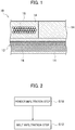
- Fig. 1 is a schematic cross-sectional diagram illustrating a configuration of a ceramic matrix composite 10.
- the ceramic matrix composite 10 includes a substrate 12 which includes fibrous bodies made of silicon carbide fiber, and a matrix 14 formed in the substrate 12.
- the ceramic matrix composite 10 can be used, for example, for gas turbine components such as a jet engine turbine blade, high-temperature components such as a rocket engine thruster, and the like.
- the substrate 12 includes fibrous bodies 16 made of silicon carbide fiber (SiC fiber), and has a function of reinforcing the ceramic matrix composite 10.
- Crystalline silicon carbide fiber and amorphous silicon carbide fiber are usable as the silicon carbide fiber.
- Crystalline silicon carbide fiber is better in heat resistance than amorphous silicon carbide fiber, and can improve the heat resistance of the ceramic matrix composite 10.
- the silicon carbide fiber is usable, for example, in the form of continuous fiber, discontinuous fiber, whisker and the like.
- three-dimensional fiber woven fabric having a three-dimensional structure which is obtained by weaving fiber bundles of hundreds to thousands of silicon carbide fiber filaments in the XYZ directions is usable as the fibrous bodies 16.
- two-dimensional fiber woven fabric and the like having a two-dimensional structure which is obtained by weaving fiber bundles of hundreds to thousands of silicon carbide fiber filaments using plain-weaving, satin-weaving or other weaving techniques is usable as the fibrous bodies 16.
- the silicon carbide fiber of each fibrous body 16 may be coated with an interface layer.
- the interface layer has a function of inhibiting the propagation of cracks and the like from the matrix 14 to the silicon carbide fiber.
- the interface layer may be made of boron nitride (BN) with excellent oxidation resistance or the like.
- the thickness of the interface layer may be, for example, 0.1 ⁇ m or more and 0.5 ⁇ m or less.
- silicon carbide layers may be provided in pores between the silicon carbide fibers of the fibrous bodies 16.
- the silicon carbide layer is capable of protecting the interface layers coating the silicon carbide fibers.
- the matrix 14 is formed in the substrate 12.
- the matrix 14 contains silicon carbide, and a silicon material made of silicon or a binary silicon alloy, but no elemental carbon.
- the matrix 14 has a function of supporting the substrate 12.
- the matrix 14 is formed in pores and the like in the substrate 12. To put it more specifically, the matrix 14 is formed, for example, in pores between fiber bundles, pores between fibers, and the like.
- the matrix 14 contains silicon carbide.
- the silicon carbide contained in the matrix 14 improves chemical stability between the silicon carbide fibers and the matrix 14, and inhibits the occurrence of cracks and the like due to the thermal expansion difference. Furthermore, the silicon carbide is excellent in oxidation resistance, and can improve the oxidation resistance of the ceramic matrix composite 10.
- the silicon carbide is formed in a particle shape.
- the matrix 14 contains the silicon material made of silicon or a binary silicon alloy.
- the silicon material is formed in gaps between the silicon carbide particles or the like.
- the silicon material has a function of making the matrix 14 dense.
- the silicon material contains silicon, and is excellent in oxidation resistance. The silicon material, therefore, can improve the oxidation resistance of the ceramic matrix composite 10.
- the silicon material can improve the heat resistance of the ceramic matrix resistance 10 since the melting point (approximately 1414 °C) of silicon is high.
- the silicon material is made of a binary silicon alloy
- the silicon material makes it possible to lower the thermal treatment temperature in the melt infiltration step (discussed later) since the melting point of the binary silicon alloy can be made lower than that of silicon. Even in a case where amorphous silicon carbide fibers are used, this makes it possible to inhibit thermal degradation in the amorphous silicon carbide fibers (grain coarsening, thermal decomposition, and the like) .
- the binary silicon alloy may be a Si-Y (Yttrium) alloy, a Si-Ti (titanium) alloy or a Si-Hf (hafnium) alloy with excellent oxidation resistance.
- the Si-Y alloy may be an alloy which contains 8 at% or more and 18 at% or less of Y, and whose rest is Si and inevitable impurities.
- the melting point of the Si-Y alloy is equal to or close to the eutectic temperature, and is accordingly lower than the melting point of elemental silicon.
- the content of silicon contained in the Si-Y alloy is large, and the thermal expansion difference between the matrix 14 and the silicon carbide fibers is smaller than otherwise. Accordingly this content makes it possible to inhibit the occurrence of cracks and the like.
- the Si-Y alloy includes, for example, Si phases and YSi 2 phases.
- the Si-Ti alloy may be an alloy which contains 8 at% or more and 18 at% or less of Ti, and whose rest is Si and inevitable impurities.
- the melting point of the Si-Ti alloy is equal to or close to the eutectic temperature, and is accordingly lower than the melting point of elemental silicon.
- the content of silicon contained in the Si-Ti alloy is large, and the thermal expansion difference between the matrix 14 and the silicon carbide fibers is smaller than otherwise. Accordingly this content makes it possible to inhibit the occurrence of cracks and the like.
- the Si-Ti alloy includes, for example, Si phases and TiSi 2 phases.
- the Si-Hf alloy may be an alloy which contains 5 at% or more and 12 at% or less of Hf, and whose rest is Si and inevitable impurities.
- the melting point of the Si-Hf alloy is equal to or close to the eutectic temperature, and is accordingly lower than the melting point of elemental silicon.
- the content of silicon contained in the Si-Hf alloy is large, and the thermal expansion difference between the matrix 14 and the silicon carbide fibers is smaller than otherwise. Accordingly this content makes it possible to inhibit the occurrence of cracks and the like.
- the Si-Hf alloy includes, for example, Si phases and HfSi 2 phases.
- the matrix 14 is formed without containing elemental carbon. "Without containing elemental carbon” means not actively making the matrix 14 contain elemental carbon while the ceramic matrix composite 10 is being manufactured. In a case where the matrix 14 contains elemental carbon such as residual carbon, carbon powder and the like caused while the ceramic matrix composite 10 is being manufactured, the oxidation resistance of the ceramic matrix composite 10 deteriorates when exposed to heat of approximately 600 °C or higher in the atmosphere because elemental carbon is oxidized to form gas which is a combination of carbon and oxygen (CO and the like) . In a case where the matrix 14 contains no elemental carbon, no such elemental carbon oxidation occurs, and the oxidation resistance of the ceramic matrix composite 10 improves.
- the matrix 14 may be made of silicon carbide, and the silicon material made of silicon or a binary silicon alloy, without containing elemental carbon.
- Fig. 2 is a flowchart illustrating a configuration of the method of manufacturing the ceramic matrix composite 10.
- the method of manufacturing the ceramic matrix composite 10 includes a powder infiltration step (S10) and a melt infiltration step (S12).
- the powder infiltration step (S10) is a step of infiltrating silicon carbide powder containing no elemental carbon into the substrate 12 which contains the fibrous bodies 16 made of the silicon carbide fiber.
- the fibrous bodies 16 contained in the substrate 12 are made of silicon carbide fiber, and includes a preform of three-dimensionally fiber woven fabric or the like. Crystalline silicon carbide fiber and amorphous silicon carbide fiber may be used as the silicon carbide fiber.
- Hi-NicalonTM Type S (Nippon Carbon Co. Ltd), Tyranno FiberTM SA-Grade (Ube Industries, Ltd.) or the like may be used as the crystalline silicon carbide fiber.
- the crystalline silicon carbide fiber is better in heat resistance than the amorphous silicon carbide fiber, and can improve the heat resistance of the ceramic matrix composite 10.
- Hi-NicalonTM (Nippon Carbon Co. Ltd), Tyranno FiberTM ZMI-Grade (Ube Industries, Ltd.) or the like may be used as the amorphous silicon carbide fiber.
- the amorphous silicon carbide fiber has a lower elastic modulus than the crystalline silicon carbide fiber, and has a larger fracture strain.
- the amorphous silicon carbide fiber therefore, makes the fibrous bodies 16 easier to form.
- the amorphous silicon carbide fiber is more inexpensive than the crystalline silicon carbide fiber, and makes it possible to reduce manufacturing costs of the ceramic matrix composite 10.
- the silicon carbide fiber of each fibrous body 16 may be coated with the interface layer made of boron nitride (BN) or the like.
- the coating of the silicon carbide fiber with the interface layer may be achieved by chemical vapor deposition (CVD) .
- silicon carbide layers may be formed in pores between the fibers of the fibrous bodies 16 by chemical vapor infiltration (CVI) before the powder infiltration step (S10).
- the silicon carbide layers can be formed in pores between the fibers of the fibrous bodies 16, for example, by setting the fibrous bodies 16 in a reactor, heating the fibrous bodies 16 (at a reaction temperature of 900 °c to 1000 °C), and using methyltrichlorosilane (CH 3 SiCl 3 ) as the reaction gas.
- the silicon carbide layers are each made in the form of a dense film by chemical vapor infiltration, and can protect the interface layers.
- the slurry includes the silicon carbide powder and a solvent. Silicon carbide powder containing no elemental carbon such as carbon powder is used as the silicon carbide powder. This makes it possible to prevent the matrix 14 from containing elemental carbon.
- the average particle diameter of the silicon carbide powder may be 1 ⁇ m or more and 10 ⁇ m or less. This is because if the average particle diameter of the silicon carbide powder is less than 1 ⁇ m, silicon carbide particles aggregate to decrease the infiltration property of the silicon carbide powder. This is also because if the average particle diameter of the silicon carbide powder is greater than 10 ⁇ m, the silicon carbide powder's property of being filled into the substrate 12 is worsened.
- the particle size of the silicon carbide powder can be adjusted by classification using a sieve.
- the particle diameters and the particle size distribution of the silicon carbide powder can be measured using a general measurement method such as a laser diffraction scattering method.
- the content of the silicon carbide powder in the slurry may be 30 volume % or more and 70 volume % or less. This is because if the content of the silicon carbide power is less than 30 volume %, the silicon carbide powder's property of being filled into the substrate 12 is worsened. This is also because if the content of the silicon carbide is greater than 70 volume %, the viscosity of the slurry is too large, and decreases the infiltration property of the silicon carbide powder.
- the content of the silicon carbide powder may be 40 volume % or more and 60 volume % or less. A commercially available product may be used as the silicon carbide powder.
- Any solvent may be used as long as the solvent is capable of dispersing the silicon carbide powder.
- ethanol, methanol, butanol, acetone, xylene, water and the like may be used as the solvent.
- a commercially available product may be used as the solvent.
- the slurry is produced by mixing the silicon carbide powder containing no elemental carbon and the solvent together using a mixer or the like.
- the slurry may include a binder.
- silica sol such as colloidal silica may be uses as the binder.
- the substrate 12 and the slurry are put into a container, and the substrate 12 is dipped into the slurry. Thereby, the slurry is infiltrated into the substrate 12.
- the inside of the container may be vacuumed using a vacuum pump or the like before or while the substrate 12 is dipped into the slurry.
- the removal of air and the like from pores in the substrate 12 by the vacuuming makes it easier to infiltrate the slurry into the substrate 12.
- ultrasonic vibration may be applied to the substrate 12 and the slurry using an ultrasonic vibrator or the like (so-called wet vibration application infiltration) while the substrate 12 is dipped in the slurry.
- the vibration frequency may be, for example, in a range of 50Hz to 30kHz.
- a length of time for which the ultrasonic vibration is applied may be, for example, in a range of 10 minutes to 30 minutes.
- the substrate 12 into which the slurry has been infiltrated is dried.
- the substrate 12 into which the slurry has been infiltrated is dried by being heated using a drier or the like. Thereby, the solvent is removed from the slurry, and the silicon carbide powder remains in the substrate 12.
- the drying temperature may be, for example, in a range of 80 °C to 100 °C.
- the drying length of time may be, for example, in a range of one hour to three hours.
- the melt infiltration step (S12) is a step of infiltrating the silicon material made of silicon or the binary silicon alloy into the substrate 12, into which the silicon carbide powder containing no elemental carbon has been infiltrated, by melting the silicon material through thermal treatment at a temperature equal to or higher than the melting point of the silicon material.
- Fig. 3 is a diagram for explaining how the melt infiltration step (S12) is performed.
- ingots or the like of the silicon material 18 made of silicon or the binary silicon alloy are disposed on the substrate 12 into which the silicon carbide powder containing no elemental carbon has been infiltrated.
- the ingots can be formed by arc melting or the like.
- the binary silicon alloy may be the Si-Y alloy, the Si-Ti alloy or the Si-Hf alloy with excellent oxidation resistance.
- the Si-Y alloy may be the alloy which contains 8 at% or more and 18 at% or less of Y, and whose rest is Si and inevitable impurities. In the case where the content of Y in the Si-Y alloy is 8 at% or more and 18 at% or less, the melting point of the Si-Y alloy can be made lower than the melting point of silicon.
- the Si-Ti alloy may be the alloy which contains 8 at% or more and 18 at% or less of Ti, and whose rest is Si and inevitable impurities. In the case where the content of Ti in the Si-Ti alloy is 8 at% or more and 18 at% or less, the melting point of the Si-Ti alloy can be made lower than the melting point of silicon.
- the Si-Hf alloy may be the alloy which contains 5 at% or more and 12 at% or less of Hf, and whose rest is Si and inevitable impurities.
- the melting point of the Si-Hf alloy can be made lower than the melting point of silicon.
- the ingots of the silicon material 18 are thermally treated after the ingots are disposed on the substrate 12 into which the silicon carbide powder containing no elemental carbon has been infiltrated.
- the thermal treatment is performed by heating at a thermal treatment temperature equal to or higher than the melting point of the silicon material 18 for the purpose of melting the silicon material 18.
- the thermal treatment is performed by heating at a thermal treatment temperature equal to or higher than the melting point (approximately 1414 °C) of silicon.
- the thermal treatment temperature may be, for example, approximately 1450 °C.
- the thermal treatment is performed by heating at a temperature equal to or higher than the melting point of the binary silicon alloy. Since the melting point of the binary silicon alloy can be made lower than that of silicon, the thermal treatment temperature can be lowered. Thus, even in the case where amorphous silicon carbide fiber is used, the thermal treatment temperature can be lowered. This lower thermal treatment temperature inhibits the thermal degradation caused by the coarsening of the grains, thermal decomposition and the like of the amorphous silicon carbide fiber, and therefore inhibits a decrease in the mechanical strength of the ceramic matrix composite 10. Furthermore, since the thermal treatment temperature can be lowered, the productivity can be improved, and the manufacturing costs can be reduced.
- the thermal treatment temperature may be equal to or higher than the melting point of the binary silicon alloy, but lower than the thermal degradation temperature of the amorphous silicon carbide fiber.
- the thermal degradation temperature of the amorphous silicon carbide fiber may be equal to a temperature at which the grains of the amorphous silicon carbide fiber coarsens and thermally decomposes.
- the thermal treatment time period may be set in a range from approximate 10 minutes to 1 hour at the thermal treatment temperature.
- the thermal treatment atmosphere may be the vacuum atmosphere, or an inert gas atmosphere using an argon gas or the like in order to inhibit the oxidation. From a viewpoint of facilitation of the infiltration, the thermal treatment atmosphere may be the vacuum atmosphere.
- a general vacuum thermal treatment furnace, a general atmospheric thermal treatment furnace or the like which is used to thermally treat metallic materials, may be used.
- the thermal treatment is performed at the thermal treatment temperature for the predetermined length of time.
- the cooling following the thermal treatment is performed to room temperature.
- the molten silicon material 18 penetrates into gaps and the like between the silicon carbide particles, and is thereby infiltrated into the gaps and the like between the silicon carbide particles. Since the silicon carbide powder does not contain elemental carbon such as carbon powder, the molten silicon material 18 is densely infiltrated into the gaps between the silicon carbide particles up to the inside of the substrate 12. To put it specifically, in the case where the silicon carbide powder contains elemental carbon, the molten silicon material 18 reacts with elemental carbon on the surface of the substrate 12, and forms silicon carbide. The thus-formed silicon carbide blocks the infiltration channels which are formed from the gaps between the silicon carbide particles, and inhibits the penetration of the molten silicon material 18 into the inside of the substrate 12.
- the infiltration channels to the inside of the substrate 12 can be secured, and the molten silicon material 18 can penetrate into the inside of the substrate 12.
- the molten silicon material 18 is densely infiltrated into the gaps between the silicon carbide particles up to the inside of the substrate 12, and inhibits the occurrence of non-infiltrated portions.
- the matrix 14 made of silicon carbide particles containing no elemental carbon, and the silicon material 18 filled in the gaps between the silicon carbide particles is densely formed in the pores, voids and the like in the substrate 12. Since the matrix 14 is densely formed, the Young's modulus of the matrix 14 can be made substantially equal to that of silicon carbide continuous fiber.
- the method of manufacturing the ceramic matrix composite 10 may be provided with a polymer impregnation and pyrolysis step of forming silicon carbide by impregnating the substrate 12 with a polymer material for forming the silicon carbide, and pyrolyzing the polymer material.
- the ceramic matrix composite includes the substrate which contains the fibrous bodies made of the silicon carbide fiber, and the matrix which is formed in the substrate, and which contains silicon carbide and the silicon material made of silicon or the binary silicon alloy, but no elemental carbon. Since the matrix contains no elemental carbon, the oxidation resistance of the ceramic matrix composite is improved.
- the method of manufacturing the ceramic matrix composite includes the powder infiltration step of infiltrating the silicon carbide powder containing no elemental carbon into the substrate which contains the fibrous bodies made of the silicon carbide fiber, and the melt infiltration step of infiltrating the silicon material made of silicon or the binary silicon alloy into the substrate, into which the silicon carbide powder containing no elemental carbon has been infiltrated, by melting the silicon material through the thermal treatment at a temperature equal to or higher than the melting point of the silicon material. Since the matrix contains no elemental carbon, the oxidation resistance of the ceramic matrix composite is improved.
- the use of the silicon carbide powder containing no elemental carbon makes it possible to enhance the molten silicon material's infiltration property, and to form the dense matrix.
- a matrix formation test was performed on the ceramic matrix composite.
- Example 1 Slurry was produced by mixing SiC powder containing no elemental carbon such as carbon powder with ethanol. SiC powder with an average particle diameter of 1 ⁇ m or more and 10 ⁇ m or less was used as the SiC powder. The slurry was poured into a rectangular mold, and was subsequently dried. Thereby, a rectangular SiC powder compact was formed.
- Si was melted and infiltrated into the SiC powder compact.
- Ingots of Si were disposed on the SiC powder compact.
- the ingots were formed by arc melting.
- the SiC powder compact with the ingots disposed thereon was put into a thermal treatment furnace, and was thermally treated in the vacuum atmosphere at a thermal treatment temperature of 1450 °C for a holding time of 20 minutes. Through this thermal treatment, the ingots were melted, and Si was melted and infiltrated into the SiC powder compact.
- the specimen of Example 1 was observed with an optical microscope.
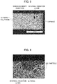
- Fig. 4 is a photograph showing a result of observing a cross section of the specimen of Example 1. In the specimen of Example 1, the molten Si penetrated into gaps between SiC particles, and the matrix was integrally densely formed.
- Example 2 A silicon material to be melted and infiltrated in Example 2 was different from that to be melted and infiltrated in Example 1, but Example 2 used the same SiC powder compact as used in Example 1.
- a Si-Y alloy was melted and infiltrated into the SiC powder compact.
- a Si-10 at% Y alloy which contained 10 at% of Y, and whose rest was Si and inevitable impurities, was used as the Si-Y alloy.
- Ingots of the Si-Y alloy were formed by arc melting. The ingots were disposed on the SiC powder compact.
- the SiC powder compact with the ingots disposed thereon was put into the thermal treatment furnace, and was thermally treated in the vacuum atmosphere at a thermal treatment temperature of 1380 °C for a holding time of 20 minutes. Through this thermal treatment, the ingots were melted, and the Si-Y was thus melted and infiltrated into the SiC powder compact.
- Example 2 An oxidation test was performed on the specimen of Example 2, and the oxidation resistance of the specimen was evaluated. Furthermore, the oxidation test was similarly performed on a specimen Comparative Example 1 made of the Si-10 at% Y alloy. The oxidation test was performed in the atmosphere at an exposure temperature of 1100 °C for an exposure time of 100 hours. After the oxidation test, cross-sections of the respective specimens were observed with the optical microscope.
- Fig. 5 is a photograph showing a result of observing the cross-section of the specimen of Comparative Example 1 after the oxidation test. As shown in Fig. 5 , it was observed that the specimen of Comparative Example 1 included Si phases and YSi 2 phases, and the YSi 2 phases and grain boundaries were preferentially oxidized.
- Fig. 6 is a photograph showing a result of observing the cross-section of the specimen of Example 2 after the oxidation test.
- the molten Si-Y alloy penetrated into gaps between SiC particles, and the matrix was integrally densely formed. Mainly Si phases were formed in the gaps between the SiC particles, and fine YSi 2 phases were dispersed in between. Internal oxidation less occurred in the specimen of Example 2 than in the specimen of Comparative Example 1, and the specimen of Example 2 was better in oxidation resistance than the specimen of Comparative Example 1.
- This is because less of the YSi 2 phases were exposed to the surface of the specimen, and the grain boundary density was small enough to inhibit the diffusion of oxygen.
- Oxidation rate constants were calculated based on increases in the respective oxidation weights in the atmosphere.
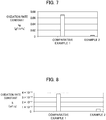
- Fig. 7 is a graph illustrating the oxidation rate constants kp in the atmosphere.
- the vertical axis represents the oxidation rate constants kp, and the lengths of the bars are respectively proportional to the values of the oxidation rate constants kp.
- the graph of Fig. 7 shows that the oxidation rate constant of the specimen of Example 2 was smaller than that of the specimen of Comparative Example 1, and the specimen of Example 2 was better in oxidation resistance than the specimen of Comparative Example 1.
- a water vapor oxidation test was performed.
- the water vapor oxidation test was performed in an oxidizing atmosphere containing water vapor at an exposure temperature of 1100 °C for an exposure time of 100 hours.
- Oxidation rate constants were calculated based on the film thicknesses of the respective oxide films.
- Fig. 8 is a graph showing the oxidation rate constants k in the oxidizing atmosphere containing water vapor.
- the vertical axis represents the oxidation rate constants k, and the lengths of the bars are respectively proportional to the values of the oxidation rate constants k.
- the graph of Fig. 8 shows that the oxidation rate constant of the specimen of Example 2 was smaller than that of the specimen of Comparative Example 1, and the specimen of Example 2 was better in water vapor oxidation resistance than the specimen of Comparative Example 1.
- Fig. 9 is a graph showing results of measuring the Young's modulus.
- the horizontal axis represents temperature, while the vertical axis represents the Young's modulus.
- Black diamonds in Fig. 9 correspond to Young's moduli at the respective temperatures. It became clear that in the environment in the temperature range of room temperature to 1000 °C, the Young's modulus of the specimen of Example 2 was substantially equal to that of the SiC continuous fiber.
- the present disclosure is effective for gas turbine components such as a jet engine turbine blade, high-temperature components such as a rocket engine thruster, and the like since the matrix in the ceramic matrix composite contains no elemental carbon and is accordingly capable of improving the oxidation resistance of the ceramic matrix composite.
Landscapes
- Chemical & Material Sciences (AREA)
- Engineering & Computer Science (AREA)
- Ceramic Engineering (AREA)
- Manufacturing & Machinery (AREA)
- Materials Engineering (AREA)
- Structural Engineering (AREA)
- Organic Chemistry (AREA)
- Inorganic Chemistry (AREA)
- Chemical Kinetics & Catalysis (AREA)
- Ceramic Products (AREA)
Abstract
Description
- The present disclosure relates to a ceramic matrix composite and a method of manufacturing the same.
- As high-temperature materials for aircraft engines, and the like, ceramic matrix composites (CMCs) have drawn attention since the specific gravities of the ceramic matrix composites are equal to or less than one third of those of heat-resistant metal materials such as Ni alloys, and the ceramic matrix composites are excellent in heat resistance. Melt infiltration is one of ceramic matrix composite manufacturing methods, and forms a matrix by infiltrating molten silicon. Melt infiltration makes it possible to manufacture a dense ceramic matrix composite by processing the matrix for a short time.
- Japanese Patent Application Publication No.
Hei 10-59780 - [PTL 1] Japanese Patent Application Publication No.
Hei 10-59780 - However, in the case where the matrix is formed by the carbon powder infiltration, the subsequent molten silicon infiltration and the reactive sintering in manufacturing the ceramic matrix composite, unreacted carbon powder is likely to remain in the matrix. If such carbon powder remains in the matrix, the carbon is oxidized to form gas which is a combination of carbon and oxygen (CO and the like), and there is a case where the oxidation resistance of the ceramic matrix composite deteriorates.
- With the above taken into consideration, an object of the present disclosure is to provide a ceramic matrix composite whose oxidation resistance can be further improved, and a method of manufacturing the same.
- A ceramic matrix composite according to an embodiment of the present invention includes a substrate which contains a fibrous body made of silicon carbide fiber, and a matrix which is formed in the substrate, and which contains silicon carbide and a silicon material made of silicon or a binary silicon alloy.
- In the ceramic matrix composite according to an embodiment of the present invention, the matrix contains no elemental carbon.
- In the ceramic matrix composite according to an embodiment of the present invention, the silicon carbide fiber is amorphous silicon carbide fiber, and the silicon material is a binary silicon alloy.
- In the ceramic matrix composite according to an embodiment of the present invention, the binary silicon alloy is a Si-Y alloy, a Si-Ti alloy or a Si-Hf alloy.
- A method of manufacturing a ceramic matrix composite according to an embodiment of the present invention includes a powder infiltration step of infiltrating silicon carbide powder containing no elemental carbon into a substrate which contains a fibrous body made of silicon carbide fiber, and a melt infiltration step of infiltrating a silicon material made of silicon or a binary silicon alloy into the substrate, into which the silicon carbide powder has been infiltrated, by melting the silicon material through thermal treatment at a temperature equal to or higher than a melting point of the silicon material.
- In the method of manufacturing a ceramic matrix composite according to an embodiment of the present invention, the silicon carbide fiber is amorphous silicon carbide fiber, and in the melt infiltrating step, the silicon material is a binary silicon alloy, and the binary silicon alloy is thermally treated at a temperature equal to or higher than the melting point of the silicon material, but lower than a thermal degradation temperature of the amorphous silicon carbide fiber.
- In the method of manufacturing a ceramic matrix composite according to an embodiment of the present invention, the binary silicon alloy is a Si-Y alloy, a Si-Ti alloy of a Si-Hf alloy.
- The foregoing configuration makes the matrix of the ceramic matrix composite contain no elemental carbon, and can accordingly improve the oxidation resistance of the ceramic matrix composite.
-
-
Fig. 1 is a schematic cross-sectional diagram illustrating a configuration of a ceramic matrix composite according to an embodiment of the present invention. -
Fig. 2 is a flowchart illustrating a configuration of a method of manufacturing a ceramic matrix composite according to the embodiment of the present invention. -
Fig. 3 is a diagram for explaining how a melt infiltration step is performed in the embodiment of the present invention. -
Fig. 4 is a photograph showing a result of observing a cross section of a specimen of Example 1 in the embodiment of the present invention. -
Fig. 5 is a photograph showing a result of observing a cross section of the specimen of Comparative Example 1 after an oxidation test in the embodiment of the present invention. -
Fig. 6 is a photograph showing a result of observing a cross section of a specimen of Example 2 after an oxidation test in the embodiment of the present invention. -
Fig. 7 is a graph showing an oxidation rate constant kp in the atmosphere in the embodiment of the present invention. -
Fig. 8 is a graph showing an oxidation rate constant k in an oxidizing atmosphere containing water vapor in the embodiment of the present invention. -
Fig. 9 is a graph showing a result of measuring a Young's modulus in the embodiment of the present invention. - Referring to the drawings, detailed descriptions will be hereinbelow provided for an embodiment of the present invention.
Fig. 1 is a schematic cross-sectional diagram illustrating a configuration of aceramic matrix composite 10. Theceramic matrix composite 10 includes asubstrate 12 which includes fibrous bodies made of silicon carbide fiber, and amatrix 14 formed in thesubstrate 12. Theceramic matrix composite 10 can be used, for example, for gas turbine components such as a jet engine turbine blade, high-temperature components such as a rocket engine thruster, and the like. - The
substrate 12 includesfibrous bodies 16 made of silicon carbide fiber (SiC fiber), and has a function of reinforcing theceramic matrix composite 10. Crystalline silicon carbide fiber and amorphous silicon carbide fiber are usable as the silicon carbide fiber. Crystalline silicon carbide fiber is better in heat resistance than amorphous silicon carbide fiber, and can improve the heat resistance of theceramic matrix composite 10. The silicon carbide fiber is usable, for example, in the form of continuous fiber, discontinuous fiber, whisker and the like. - For example, three-dimensional fiber woven fabric having a three-dimensional structure which is obtained by weaving fiber bundles of hundreds to thousands of silicon carbide fiber filaments in the XYZ directions is usable as the
fibrous bodies 16. Otherwise, two-dimensional fiber woven fabric and the like having a two-dimensional structure which is obtained by weaving fiber bundles of hundreds to thousands of silicon carbide fiber filaments using plain-weaving, satin-weaving or other weaving techniques is usable as thefibrous bodies 16. - The silicon carbide fiber of each
fibrous body 16 may be coated with an interface layer. The interface layer has a function of inhibiting the propagation of cracks and the like from thematrix 14 to the silicon carbide fiber. The interface layer may be made of boron nitride (BN) with excellent oxidation resistance or the like. The thickness of the interface layer may be, for example, 0.1 µm or more and 0.5 µm or less. - In the
substrate 12, silicon carbide layers may be provided in pores between the silicon carbide fibers of thefibrous bodies 16. The silicon carbide layer is capable of protecting the interface layers coating the silicon carbide fibers. - The
matrix 14 is formed in thesubstrate 12. Thematrix 14 contains silicon carbide, and a silicon material made of silicon or a binary silicon alloy, but no elemental carbon. Thematrix 14 has a function of supporting thesubstrate 12. Thematrix 14 is formed in pores and the like in thesubstrate 12. To put it more specifically, thematrix 14 is formed, for example, in pores between fiber bundles, pores between fibers, and the like. - The
matrix 14 contains silicon carbide. The silicon carbide contained in thematrix 14 improves chemical stability between the silicon carbide fibers and thematrix 14, and inhibits the occurrence of cracks and the like due to the thermal expansion difference. Furthermore, the silicon carbide is excellent in oxidation resistance, and can improve the oxidation resistance of theceramic matrix composite 10. The silicon carbide is formed in a particle shape. - The
matrix 14 contains the silicon material made of silicon or a binary silicon alloy. The silicon material is formed in gaps between the silicon carbide particles or the like. The silicon material has a function of making thematrix 14 dense. In addition, the silicon material contains silicon, and is excellent in oxidation resistance. The silicon material, therefore, can improve the oxidation resistance of theceramic matrix composite 10. - In the case where the silicon material is made of silicon, the silicon material can improve the heat resistance of the
ceramic matrix resistance 10 since the melting point (approximately 1414 °C) of silicon is high. - In the case where the silicon material is made of a binary silicon alloy, the silicon material makes it possible to lower the thermal treatment temperature in the melt infiltration step (discussed later) since the melting point of the binary silicon alloy can be made lower than that of silicon. Even in a case where amorphous silicon carbide fibers are used, this makes it possible to inhibit thermal degradation in the amorphous silicon carbide fibers (grain coarsening, thermal decomposition, and the like) . The binary silicon alloy may be a Si-Y (Yttrium) alloy, a Si-Ti (titanium) alloy or a Si-Hf (hafnium) alloy with excellent oxidation resistance.
- The Si-Y alloy may be an alloy which contains 8 at% or more and 18 at% or less of Y, and whose rest is Si and inevitable impurities. In the case where the content of Y is 8 at% or more and 18 at% or less, the melting point of the Si-Y alloy is equal to or close to the eutectic temperature, and is accordingly lower than the melting point of elemental silicon. In addition, in the case where the content of Y is 8 at% or more and 18 at% or less, the content of silicon contained in the Si-Y alloy is large, and the thermal expansion difference between the
matrix 14 and the silicon carbide fibers is smaller than otherwise. Accordingly this content makes it possible to inhibit the occurrence of cracks and the like. In the case where the content of Y is 8 at% or more and 18 at% or less, the Si-Y alloy includes, for example, Si phases and YSi2 phases. - The Si-Ti alloy may be an alloy which contains 8 at% or more and 18 at% or less of Ti, and whose rest is Si and inevitable impurities. In the case where the content of Ti is 8 at% or more and 18 at% or less, the melting point of the Si-Ti alloy is equal to or close to the eutectic temperature, and is accordingly lower than the melting point of elemental silicon. In addition, in the case where the content of Ti is 8 at% or more and 18 at% or less, the content of silicon contained in the Si-Ti alloy is large, and the thermal expansion difference between the
matrix 14 and the silicon carbide fibers is smaller than otherwise. Accordingly this content makes it possible to inhibit the occurrence of cracks and the like. In the case where the content of Ti is 8 at% or more and 18 at% or less, the Si-Ti alloy includes, for example, Si phases and TiSi2 phases. - The Si-Hf alloy may be an alloy which contains 5 at% or more and 12 at% or less of Hf, and whose rest is Si and inevitable impurities. In the case where the content of Hf is 5 at% or more and 12 at% or less, the melting point of the Si-Hf alloy is equal to or close to the eutectic temperature, and is accordingly lower than the melting point of elemental silicon. In addition, in the case where the content of Hf is 5 at% or more and 12 at% or less, the content of silicon contained in the Si-Hf alloy is large, and the thermal expansion difference between the
matrix 14 and the silicon carbide fibers is smaller than otherwise. Accordingly this content makes it possible to inhibit the occurrence of cracks and the like. In the case where the content of Hf is 5 at% or more and 12 at% or less, the Si-Hf alloy includes, for example, Si phases and HfSi2 phases. - The
matrix 14 is formed without containing elemental carbon. "Without containing elemental carbon" means not actively making thematrix 14 contain elemental carbon while theceramic matrix composite 10 is being manufactured. In a case where thematrix 14 contains elemental carbon such as residual carbon, carbon powder and the like caused while theceramic matrix composite 10 is being manufactured, the oxidation resistance of theceramic matrix composite 10 deteriorates when exposed to heat of approximately 600 °C or higher in the atmosphere because elemental carbon is oxidized to form gas which is a combination of carbon and oxygen (CO and the like) . In a case where thematrix 14 contains no elemental carbon, no such elemental carbon oxidation occurs, and the oxidation resistance of theceramic matrix composite 10 improves. Thematrix 14 may be made of silicon carbide, and the silicon material made of silicon or a binary silicon alloy, without containing elemental carbon. - Next, descriptions will be provided for a method of manufacturing the
ceramic matrix composite 10.Fig. 2 is a flowchart illustrating a configuration of the method of manufacturing theceramic matrix composite 10. The method of manufacturing theceramic matrix composite 10 includes a powder infiltration step (S10) and a melt infiltration step (S12). - The powder infiltration step (S10) is a step of infiltrating silicon carbide powder containing no elemental carbon into the
substrate 12 which contains thefibrous bodies 16 made of the silicon carbide fiber. - To begin with, the
substrate 12 will be described. Thefibrous bodies 16 contained in thesubstrate 12 are made of silicon carbide fiber, and includes a preform of three-dimensionally fiber woven fabric or the like. Crystalline silicon carbide fiber and amorphous silicon carbide fiber may be used as the silicon carbide fiber. - For example, Hi-Nicalon™ Type S (Nippon Carbon Co. Ltd), Tyranno Fiber™ SA-Grade (Ube Industries, Ltd.) or the like may be used as the crystalline silicon carbide fiber. The crystalline silicon carbide fiber is better in heat resistance than the amorphous silicon carbide fiber, and can improve the heat resistance of the
ceramic matrix composite 10. - For example, Hi-Nicalon™ (Nippon Carbon Co. Ltd), Tyranno Fiber™ ZMI-Grade (Ube Industries, Ltd.) or the like may be used as the amorphous silicon carbide fiber. The amorphous silicon carbide fiber has a lower elastic modulus than the crystalline silicon carbide fiber, and has a larger fracture strain. The amorphous silicon carbide fiber, therefore, makes the
fibrous bodies 16 easier to form. Furthermore, the amorphous silicon carbide fiber is more inexpensive than the crystalline silicon carbide fiber, and makes it possible to reduce manufacturing costs of theceramic matrix composite 10. - The silicon carbide fiber of each
fibrous body 16 may be coated with the interface layer made of boron nitride (BN) or the like. The coating of the silicon carbide fiber with the interface layer may be achieved by chemical vapor deposition (CVD) . - In the
substrate 12, silicon carbide layers may be formed in pores between the fibers of thefibrous bodies 16 by chemical vapor infiltration (CVI) before the powder infiltration step (S10). The silicon carbide layers can be formed in pores between the fibers of thefibrous bodies 16, for example, by setting thefibrous bodies 16 in a reactor, heating the fibrous bodies 16 (at a reaction temperature of 900 °c to 1000 °C), and using methyltrichlorosilane (CH3SiCl3) as the reaction gas. The silicon carbide layers are each made in the form of a dense film by chemical vapor infiltration, and can protect the interface layers. - Next, descriptions will be provided for a powder infiltration method. First of all, slurry for infiltrating the silicon carbide powder containing no elemental carbon is produced. The slurry includes the silicon carbide powder and a solvent. Silicon carbide powder containing no elemental carbon such as carbon powder is used as the silicon carbide powder. This makes it possible to prevent the
matrix 14 from containing elemental carbon. - The average particle diameter of the silicon carbide powder may be 1 µm or more and 10 µm or less. This is because if the average particle diameter of the silicon carbide powder is less than 1 µm, silicon carbide particles aggregate to decrease the infiltration property of the silicon carbide powder. This is also because if the average particle diameter of the silicon carbide powder is greater than 10 µm, the silicon carbide powder's property of being filled into the
substrate 12 is worsened. The particle size of the silicon carbide powder can be adjusted by classification using a sieve. The particle diameters and the particle size distribution of the silicon carbide powder can be measured using a general measurement method such as a laser diffraction scattering method. - The content of the silicon carbide powder in the slurry may be 30 volume % or more and 70 volume % or less. This is because if the content of the silicon carbide power is less than 30 volume %, the silicon carbide powder's property of being filled into the
substrate 12 is worsened. This is also because if the content of the silicon carbide is greater than 70 volume %, the viscosity of the slurry is too large, and decreases the infiltration property of the silicon carbide powder. The content of the silicon carbide powder may be 40 volume % or more and 60 volume % or less. A commercially available product may be used as the silicon carbide powder. - Any solvent may be used as long as the solvent is capable of dispersing the silicon carbide powder. For example, ethanol, methanol, butanol, acetone, xylene, water and the like may be used as the solvent. A commercially available product may be used as the solvent.
- The slurry is produced by mixing the silicon carbide powder containing no elemental carbon and the solvent together using a mixer or the like. The slurry may include a binder. For example, silica sol such as colloidal silica may be uses as the binder.
- The
substrate 12 and the slurry are put into a container, and thesubstrate 12 is dipped into the slurry. Thereby, the slurry is infiltrated into thesubstrate 12. The inside of the container may be vacuumed using a vacuum pump or the like before or while thesubstrate 12 is dipped into the slurry. The removal of air and the like from pores in thesubstrate 12 by the vacuuming makes it easier to infiltrate the slurry into thesubstrate 12. - For the purpose of facilitating the infiltration of the slurry into the
substrate 12, ultrasonic vibration may be applied to thesubstrate 12 and the slurry using an ultrasonic vibrator or the like (so-called wet vibration application infiltration) while thesubstrate 12 is dipped in the slurry. The vibration frequency may be, for example, in a range of 50Hz to 30kHz. A length of time for which the ultrasonic vibration is applied may be, for example, in a range of 10 minutes to 30 minutes. - Thereafter, the
substrate 12 into which the slurry has been infiltrated is dried. Thesubstrate 12 into which the slurry has been infiltrated is dried by being heated using a drier or the like. Thereby, the solvent is removed from the slurry, and the silicon carbide powder remains in thesubstrate 12. The drying temperature may be, for example, in a range of 80 °C to 100 °C. The drying length of time may be, for example, in a range of one hour to three hours. - The melt infiltration step (S12) is a step of infiltrating the silicon material made of silicon or the binary silicon alloy into the
substrate 12, into which the silicon carbide powder containing no elemental carbon has been infiltrated, by melting the silicon material through thermal treatment at a temperature equal to or higher than the melting point of the silicon material.Fig. 3 is a diagram for explaining how the melt infiltration step (S12) is performed. - As illustrated in
Fig. 3 , ingots or the like of thesilicon material 18 made of silicon or the binary silicon alloy are disposed on thesubstrate 12 into which the silicon carbide powder containing no elemental carbon has been infiltrated. The ingots can be formed by arc melting or the like. The binary silicon alloy may be the Si-Y alloy, the Si-Ti alloy or the Si-Hf alloy with excellent oxidation resistance. - The Si-Y alloy may be the alloy which contains 8 at% or more and 18 at% or less of Y, and whose rest is Si and inevitable impurities. In the case where the content of Y in the Si-Y alloy is 8 at% or more and 18 at% or less, the melting point of the Si-Y alloy can be made lower than the melting point of silicon.
- The Si-Ti alloy may be the alloy which contains 8 at% or more and 18 at% or less of Ti, and whose rest is Si and inevitable impurities. In the case where the content of Ti in the Si-Ti alloy is 8 at% or more and 18 at% or less, the melting point of the Si-Ti alloy can be made lower than the melting point of silicon.
- The Si-Hf alloy may be the alloy which contains 5 at% or more and 12 at% or less of Hf, and whose rest is Si and inevitable impurities. In the case where the content of Hf in the Si-Hf alloy is 5 at% or more and 12 at% or less, the melting point of the Si-Hf alloy can be made lower than the melting point of silicon.
- The ingots of the
silicon material 18 are thermally treated after the ingots are disposed on thesubstrate 12 into which the silicon carbide powder containing no elemental carbon has been infiltrated. The thermal treatment is performed by heating at a thermal treatment temperature equal to or higher than the melting point of thesilicon material 18 for the purpose of melting thesilicon material 18. - In the case where the
silicon material 18 is made of silicon, the thermal treatment is performed by heating at a thermal treatment temperature equal to or higher than the melting point (approximately 1414 °C) of silicon. The thermal treatment temperature may be, for example, approximately 1450 °C. - In the case where the
silicon material 18 is made of the binary silicon alloy, the thermal treatment is performed by heating at a temperature equal to or higher than the melting point of the binary silicon alloy. Since the melting point of the binary silicon alloy can be made lower than that of silicon, the thermal treatment temperature can be lowered. Thus, even in the case where amorphous silicon carbide fiber is used, the thermal treatment temperature can be lowered. This lower thermal treatment temperature inhibits the thermal degradation caused by the coarsening of the grains, thermal decomposition and the like of the amorphous silicon carbide fiber, and therefore inhibits a decrease in the mechanical strength of theceramic matrix composite 10. Furthermore, since the thermal treatment temperature can be lowered, the productivity can be improved, and the manufacturing costs can be reduced. The thermal treatment temperature may be equal to or higher than the melting point of the binary silicon alloy, but lower than the thermal degradation temperature of the amorphous silicon carbide fiber. The thermal degradation temperature of the amorphous silicon carbide fiber may be equal to a temperature at which the grains of the amorphous silicon carbide fiber coarsens and thermally decomposes. - The thermal treatment time period may be set in a range from approximate 10 minutes to 1 hour at the thermal treatment temperature. The thermal treatment atmosphere may be the vacuum atmosphere, or an inert gas atmosphere using an argon gas or the like in order to inhibit the oxidation. From a viewpoint of facilitation of the infiltration, the thermal treatment atmosphere may be the vacuum atmosphere. As for the thermal treatment facility, a general vacuum thermal treatment furnace, a general atmospheric thermal treatment furnace or the like, which is used to thermally treat metallic materials, may be used. The thermal treatment is performed at the thermal treatment temperature for the predetermined length of time. The cooling following the thermal treatment is performed to room temperature.
- The
molten silicon material 18 penetrates into gaps and the like between the silicon carbide particles, and is thereby infiltrated into the gaps and the like between the silicon carbide particles. Since the silicon carbide powder does not contain elemental carbon such as carbon powder, themolten silicon material 18 is densely infiltrated into the gaps between the silicon carbide particles up to the inside of thesubstrate 12. To put it specifically, in the case where the silicon carbide powder contains elemental carbon, themolten silicon material 18 reacts with elemental carbon on the surface of thesubstrate 12, and forms silicon carbide. The thus-formed silicon carbide blocks the infiltration channels which are formed from the gaps between the silicon carbide particles, and inhibits the penetration of themolten silicon material 18 into the inside of thesubstrate 12. In contrast to this, in the case where the silicon carbide powder contains no elemental carbon, almost no reaction occurs between the silicon carbide powder and themolten silicon material 18. Thus, the infiltration channels to the inside of thesubstrate 12 can be secured, and themolten silicon material 18 can penetrate into the inside of thesubstrate 12. Themolten silicon material 18 is densely infiltrated into the gaps between the silicon carbide particles up to the inside of thesubstrate 12, and inhibits the occurrence of non-infiltrated portions. Thereby, thematrix 14 made of silicon carbide particles containing no elemental carbon, and thesilicon material 18 filled in the gaps between the silicon carbide particles is densely formed in the pores, voids and the like in thesubstrate 12. Since thematrix 14 is densely formed, the Young's modulus of thematrix 14 can be made substantially equal to that of silicon carbide continuous fiber. - It should be noted that after the melt infiltration step (S12), the method of manufacturing the
ceramic matrix composite 10 may be provided with a polymer impregnation and pyrolysis step of forming silicon carbide by impregnating thesubstrate 12 with a polymer material for forming the silicon carbide, and pyrolyzing the polymer material. - As discussed above, according to the foregoing configuration, the ceramic matrix composite includes the substrate which contains the fibrous bodies made of the silicon carbide fiber, and the matrix which is formed in the substrate, and which contains silicon carbide and the silicon material made of silicon or the binary silicon alloy, but no elemental carbon. Since the matrix contains no elemental carbon, the oxidation resistance of the ceramic matrix composite is improved.
- According to the foregoing configuration, the method of manufacturing the ceramic matrix composite includes the powder infiltration step of infiltrating the silicon carbide powder containing no elemental carbon into the substrate which contains the fibrous bodies made of the silicon carbide fiber, and the melt infiltration step of infiltrating the silicon material made of silicon or the binary silicon alloy into the substrate, into which the silicon carbide powder containing no elemental carbon has been infiltrated, by melting the silicon material through the thermal treatment at a temperature equal to or higher than the melting point of the silicon material. Since the matrix contains no elemental carbon, the oxidation resistance of the ceramic matrix composite is improved. In addition, the use of the silicon carbide powder containing no elemental carbon makes it possible to enhance the molten silicon material's infiltration property, and to form the dense matrix.
- A matrix formation test was performed on the ceramic matrix composite.
- To begin with, descriptions will be provided for Example 1. Slurry was produced by mixing SiC powder containing no elemental carbon such as carbon powder with ethanol. SiC powder with an average particle diameter of 1 µm or more and 10 µm or less was used as the SiC powder. The slurry was poured into a rectangular mold, and was subsequently dried. Thereby, a rectangular SiC powder compact was formed.
- Si was melted and infiltrated into the SiC powder compact. Ingots of Si were disposed on the SiC powder compact. The ingots were formed by arc melting. The SiC powder compact with the ingots disposed thereon was put into a thermal treatment furnace, and was thermally treated in the vacuum atmosphere at a thermal treatment temperature of 1450 °C for a holding time of 20 minutes. Through this thermal treatment, the ingots were melted, and Si was melted and infiltrated into the SiC powder compact. The specimen of Example 1 was observed with an optical microscope.
Fig. 4 is a photograph showing a result of observing a cross section of the specimen of Example 1. In the specimen of Example 1, the molten Si penetrated into gaps between SiC particles, and the matrix was integrally densely formed. - Next, descriptions will be provided for Example 2. A silicon material to be melted and infiltrated in Example 2 was different from that to be melted and infiltrated in Example 1, but Example 2 used the same SiC powder compact as used in Example 1. In Example 2, a Si-Y alloy was melted and infiltrated into the SiC powder compact. A Si-10 at% Y alloy which contained 10 at% of Y, and whose rest was Si and inevitable impurities, was used as the Si-Y alloy. Ingots of the Si-Y alloy were formed by arc melting. The ingots were disposed on the SiC powder compact. The SiC powder compact with the ingots disposed thereon was put into the thermal treatment furnace, and was thermally treated in the vacuum atmosphere at a thermal treatment temperature of 1380 °C for a holding time of 20 minutes. Through this thermal treatment, the ingots were melted, and the Si-Y was thus melted and infiltrated into the SiC powder compact.
- An oxidation test was performed on the specimen of Example 2, and the oxidation resistance of the specimen was evaluated. Furthermore, the oxidation test was similarly performed on a specimen Comparative Example 1 made of the Si-10 at% Y alloy. The oxidation test was performed in the atmosphere at an exposure temperature of 1100 °C for an exposure time of 100 hours. After the oxidation test, cross-sections of the respective specimens were observed with the optical microscope.
-
Fig. 5 is a photograph showing a result of observing the cross-section of the specimen of Comparative Example 1 after the oxidation test. As shown inFig. 5 , it was observed that the specimen of Comparative Example 1 included Si phases and YSi2 phases, and the YSi2 phases and grain boundaries were preferentially oxidized. -
Fig. 6 is a photograph showing a result of observing the cross-section of the specimen of Example 2 after the oxidation test. In the specimen of Example 2, the molten Si-Y alloy penetrated into gaps between SiC particles, and the matrix was integrally densely formed. Mainly Si phases were formed in the gaps between the SiC particles, and fine YSi2 phases were dispersed in between. Internal oxidation less occurred in the specimen of Example 2 than in the specimen of Comparative Example 1, and the specimen of Example 2 was better in oxidation resistance than the specimen of Comparative Example 1. One may consider that this is because less of the YSi2 phases were exposed to the surface of the specimen, and the grain boundary density was small enough to inhibit the diffusion of oxygen. - Oxidation rate constants were calculated based on increases in the respective oxidation weights in the atmosphere.
Fig. 7 is a graph illustrating the oxidation rate constants kp in the atmosphere. InFig. 7 , the vertical axis represents the oxidation rate constants kp, and the lengths of the bars are respectively proportional to the values of the oxidation rate constants kp. The graph ofFig. 7 shows that the oxidation rate constant of the specimen of Example 2 was smaller than that of the specimen of Comparative Example 1, and the specimen of Example 2 was better in oxidation resistance than the specimen of Comparative Example 1. - Thereafter, a water vapor oxidation test was performed. The water vapor oxidation test was performed in an oxidizing atmosphere containing water vapor at an exposure temperature of 1100 °C for an exposure time of 100 hours. Oxidation rate constants were calculated based on the film thicknesses of the respective oxide films.
Fig. 8 is a graph showing the oxidation rate constants k in the oxidizing atmosphere containing water vapor. InFig. 8 , the vertical axis represents the oxidation rate constants k, and the lengths of the bars are respectively proportional to the values of the oxidation rate constants k. The graph ofFig. 8 shows that the oxidation rate constant of the specimen of Example 2 was smaller than that of the specimen of Comparative Example 1, and the specimen of Example 2 was better in water vapor oxidation resistance than the specimen of Comparative Example 1. - Thereafter, the Young's modulus of the specimen of Example 2 was measured. The Young's modulus was measured by a resonance method in the atmosphere in a temperature range of room temperature to 1000 °C.
Fig. 9 is a graph showing results of measuring the Young's modulus. InFig. 9 , the horizontal axis represents temperature, while the vertical axis represents the Young's modulus. Black diamonds inFig. 9 correspond to Young's moduli at the respective temperatures. It became clear that in the environment in the temperature range of room temperature to 1000 °C, the Young's modulus of the specimen of Example 2 was substantially equal to that of the SiC continuous fiber. - The present disclosure is effective for gas turbine components such as a jet engine turbine blade, high-temperature components such as a rocket engine thruster, and the like since the matrix in the ceramic matrix composite contains no elemental carbon and is accordingly capable of improving the oxidation resistance of the ceramic matrix composite.
Claims (8)
- A ceramic matrix composite comprising:a substrate which contains a fibrous body made of silicon carbide fiber; anda matrix which is formed in the substrate, and which contains silicon carbide and a silicon material made of silicon or a binary silicon alloy.
- The ceramic matrix composite according to claim 1, wherein the matrix contains no elemental carbon.
- The ceramic matrix composite according to claim 1 or 2, wherein
the silicon carbide fiber is amorphous silicon carbide fiber, and
the silicon material is a binary silicon alloy. - The ceramic matrix composite according to claim 1 or 2, wherein the binary silicon alloy is a Si-Y alloy, a Si-Ti alloy or a Si-Hf alloy.
- The ceramic matrix composite according to claim 3, wherein the binary silicon alloy is a Si-Y alloy, a Si-Ti alloy or a Si-Hf alloy.
- A method of manufacturing a ceramic matrix composite, comprising:
a powder infiltration step of infiltrating silicon carbide powder containing no elemental carbon into a substrate which contains a fibrous body made of silicon carbide fiber; and
a melt infiltration step of infiltrating a silicon material made of silicon or a binary silicon alloy into the substrate, into which the silicon carbide powder has been infiltrated, by melting the silicon material through thermal treatment at a temperature equal to or higher than a melting point of the silicon material. - The method of manufacturing a ceramic matrix composite according to claim 6, wherein
the silicon carbide fiber is amorphous silicon carbide fiber, and
in the melt infiltrating step, the silicon material is a binary silicon alloy, and the binary silicon alloy is thermally treated at a temperature equal to or higher than the melting point of the silicon material, but lower than a thermal degradation temperature of the amorphous silicon carbide fiber. - The method of manufacturing a ceramic matrix composite according to claim 6 or 7, wherein the binary silicon alloy is a Si-Y alloy, a Si-Ti alloy or a Si-Hf alloy.
Applications Claiming Priority (2)
| Application Number | Priority Date | Filing Date | Title |
|---|---|---|---|
| JP2016164731 | 2016-08-25 | ||
| PCT/JP2017/015243 WO2018037617A1 (en) | 2016-08-25 | 2017-04-14 | Ceramic base composite material and method for producing same |
Publications (2)
| Publication Number | Publication Date |
|---|---|
| EP3505502A1 true EP3505502A1 (en) | 2019-07-03 |
| EP3505502A4 EP3505502A4 (en) | 2020-03-25 |
Family
ID=61245753
Family Applications (1)
| Application Number | Title | Priority Date | Filing Date |
|---|---|---|---|
| EP17843107.8A Pending EP3505502A4 (en) | 2016-08-25 | 2017-04-14 | CERAMIC-BASED COMPOSITE MATERIAL AND METHOD FOR THE PRODUCTION THEREOF |
Country Status (4)
| Country | Link |
|---|---|
| US (1) | US11548828B2 (en) |
| EP (1) | EP3505502A4 (en) |
| JP (1) | JP6658897B2 (en) |
| WO (1) | WO2018037617A1 (en) |
Cited By (2)
| Publication number | Priority date | Publication date | Assignee | Title |
|---|---|---|---|---|
| CN113480320A (en) * | 2021-07-02 | 2021-10-08 | 中国科学院上海硅酸盐研究所 | High-stress-cracking-resistance SiCf/SiC ceramic matrix composite material and preparation method thereof |
| US20240002296A1 (en) * | 2020-12-04 | 2024-01-04 | Ihi Aerospace Co., Ltd. | Ceramic matrix composite and method for manufacturing same |
Families Citing this family (4)
| Publication number | Priority date | Publication date | Assignee | Title |
|---|---|---|---|---|
| CN109415275B (en) * | 2016-09-06 | 2021-08-24 | 株式会社Ihi | Manufacturing method of ceramic matrix composites |
| JP7173372B2 (en) * | 2019-10-17 | 2022-11-16 | 株式会社Ihi | Ceramic matrix composite material and its manufacturing method |
| CN111243681B (en) * | 2020-01-15 | 2023-08-01 | 南京航空航天大学 | Method for predicting internal oxidation morphology of ceramic matrix composite in stress oxidation environment |
| CN111170754B (en) * | 2020-02-08 | 2022-05-13 | 西北工业大学 | Composite material with Si-Y-C ternary ceramic matrix and preparation method thereof |
Family Cites Families (17)
| Publication number | Priority date | Publication date | Assignee | Title |
|---|---|---|---|---|
| US5296311A (en) * | 1992-03-17 | 1994-03-22 | The Carborundum Company | Silicon carbide reinforced reaction bonded silicon carbide composite |
| CN1102632A (en) | 1993-06-25 | 1995-05-17 | 株式会社日立制作所 | Fibre reinforcement composite, making of same and unit made of same |
| JPH07223876A (en) | 1993-06-25 | 1995-08-22 | Hitachi Ltd | Fiber-reinforced composite material, manufacturing method thereof and member using the same |
| JPH1059780A (en) | 1996-08-20 | 1998-03-03 | Toshiba Corp | Ceramic based fiber composite material and method for producing the same |
| US5840221A (en) * | 1996-12-02 | 1998-11-24 | Saint-Gobain/Norton Industrial Ceramics Corporation | Process for making silicon carbide reinforced silicon carbide composite |
| JPH10167831A (en) * | 1996-12-16 | 1998-06-23 | Ngk Insulators Ltd | SiC fiber reinforced Si-SiC composite material and method for producing the same |
| JP4907777B2 (en) * | 2001-04-02 | 2012-04-04 | 太平洋セメント株式会社 | Metal-ceramic composite material |
| DE10133635A1 (en) | 2001-07-11 | 2003-02-06 | Sgl Carbon Ag | Multi-layer ceramic composite |
| FR2869609B1 (en) * | 2004-05-03 | 2006-07-28 | Snecma Propulsion Solide Sa | PROCESS FOR MANUFACTURING A THERMOSTRUCTURAL COMPOSITE MATERIAL PART |
| JP2011011922A (en) | 2009-06-30 | 2011-01-20 | Hitachi Chem Co Ltd | Carbon/silicon carbide system composite material |
| JP5916088B2 (en) | 2012-01-18 | 2016-05-11 | 国立研究開発法人宇宙航空研究開発機構 | Method for producing ceramic fiber reinforced composite material and ceramic fiber reinforced composite material |
| US20130287941A1 (en) * | 2012-04-27 | 2013-10-31 | General Electric Company | Method of producing a melt-infiltrated ceramic matrix composite article |
| US9726025B2 (en) * | 2013-03-15 | 2017-08-08 | Rolls-Royce Corporation | Ceramic matrix composite |
| FR3008968B1 (en) * | 2013-07-23 | 2016-12-09 | Herakles | PROCESS FOR MANUFACTURING COMPOSITE MATERIAL PARTS BY LOW TEMPERATURE FUSION IMPREGNATION |
| US10017424B2 (en) * | 2014-12-04 | 2018-07-10 | Rolls-Royce Corporation | Ceramic matrix composites and methods of making the same |
| JP2016150873A (en) * | 2015-02-18 | 2016-08-22 | 株式会社Ihi | Method for producing ceramic-based composite material |
| FR3047988B1 (en) * | 2016-02-18 | 2018-03-16 | Centre National De La Recherche Scientifique | METHOD FOR MANUFACTURING A PIECE OF CERAMIC MATRIX COMPOSITE MATERIAL |
-
2017
- 2017-04-14 WO PCT/JP2017/015243 patent/WO2018037617A1/en not_active Ceased
- 2017-04-14 EP EP17843107.8A patent/EP3505502A4/en active Pending
- 2017-04-14 JP JP2018536053A patent/JP6658897B2/en active Active
-
2018
- 2018-11-20 US US16/196,179 patent/US11548828B2/en active Active
Cited By (2)
| Publication number | Priority date | Publication date | Assignee | Title |
|---|---|---|---|---|
| US20240002296A1 (en) * | 2020-12-04 | 2024-01-04 | Ihi Aerospace Co., Ltd. | Ceramic matrix composite and method for manufacturing same |
| CN113480320A (en) * | 2021-07-02 | 2021-10-08 | 中国科学院上海硅酸盐研究所 | High-stress-cracking-resistance SiCf/SiC ceramic matrix composite material and preparation method thereof |
Also Published As
| Publication number | Publication date |
|---|---|
| US20200024198A1 (en) | 2020-01-23 |
| EP3505502A4 (en) | 2020-03-25 |
| JPWO2018037617A1 (en) | 2019-04-18 |
| WO2018037617A1 (en) | 2018-03-01 |
| US11548828B2 (en) | 2023-01-10 |
| JP6658897B2 (en) | 2020-03-04 |
Similar Documents
| Publication | Publication Date | Title |
|---|---|---|
| US11548828B2 (en) | Ceramic matrix composite and method of manufacturing the same | |
| JP5916088B2 (en) | Method for producing ceramic fiber reinforced composite material and ceramic fiber reinforced composite material | |
| US9611180B2 (en) | Method for manufacturing a part made of CMC | |
| JP4106086B2 (en) | Ceramic matrix fiber composite material | |
| EP2248786A1 (en) | Process of producing ceramic matrix composites | |
| US8545938B2 (en) | Method of fabricating a ceramic component | |
| JP2001505522A (en) | Silicon carbide reinforced silicon carbide composite material | |
| JP2015508382A (en) | Method of manufacturing a ceramic matrix composite and ceramic matrix composite formed thereby | |
| JPH05105521A (en) | Carbon-fiber reinforced silicon nitride-based nano-composite material and its production | |
| CN105408288A (en) | Method for manufacturing composite parts by low melting point impregnation | |
| US11987533B2 (en) | Ceramic matrix composite component and method of producing the same | |
| EP2918569A1 (en) | Process of producing ceramic matrix composites | |
| CN109415275B (en) | Manufacturing method of ceramic matrix composites | |
| CN100564319C (en) | Composite material and its manufacturing method | |
| EP3957620B1 (en) | Method of making a ceramic matrix composite that exhibits moisture and environmental resistance | |
| Abdollahi et al. | High temperature anti‐oxidation behavior of in situ and ex situ nanostructured C/SiC/ZrB2‐SiC gradient coatings: Thermodynamical evolution, microstructural characterization, and residual stress analysis | |
| JPH09268065A (en) | Long fiber composite ceramics and manufacturing method thereof | |
| Mohammad et al. | Development and characterization of Silicon Carbide coating on Graphite substrate | |
| EP3568382B1 (en) | Melt infiltration with siga and/or siin alloys | |
| Perevislov et al. | Preparation and properties of reinforced engineering materials | |
| US20190023618A1 (en) | Composite material and method for making | |
| EP2574604B1 (en) | Method for Fabricating Ceramic Material | |
| Tülbez | Processing and characterization of carbon fiber reinforced silicon carbide (C/C-SiC) matrix composites | |
| CN105985113A (en) | Process for producing ceramic matrix compound and ceramic matrix compound formed through process | |
| JPH09268063A (en) | Ceramic-based fiber composite material |
Legal Events
| Date | Code | Title | Description |
|---|---|---|---|
| STAA | Information on the status of an ep patent application or granted ep patent |
Free format text: STATUS: THE INTERNATIONAL PUBLICATION HAS BEEN MADE |
|
| PUAI | Public reference made under article 153(3) epc to a published international application that has entered the european phase |
Free format text: ORIGINAL CODE: 0009012 |
|
| STAA | Information on the status of an ep patent application or granted ep patent |
Free format text: STATUS: REQUEST FOR EXAMINATION WAS MADE |
|
| 17P | Request for examination filed |
Effective date: 20190325 |
|
| AK | Designated contracting states |
Kind code of ref document: A1 Designated state(s): AL AT BE BG CH CY CZ DE DK EE ES FI FR GB GR HR HU IE IS IT LI LT LU LV MC MK MT NL NO PL PT RO RS SE SI SK SM TR |
|
| AX | Request for extension of the european patent |
Extension state: BA ME |
|
| DAV | Request for validation of the european patent (deleted) | ||
| DAX | Request for extension of the european patent (deleted) | ||
| A4 | Supplementary search report drawn up and despatched |
Effective date: 20200226 |
|
| RIC1 | Information provided on ipc code assigned before grant |
Ipc: C04B 35/63 20060101ALI20200219BHEP Ipc: C04B 35/80 20060101AFI20200219BHEP Ipc: C04B 35/565 20060101ALI20200219BHEP Ipc: C04B 35/628 20060101ALI20200219BHEP |
|
| STAA | Information on the status of an ep patent application or granted ep patent |
Free format text: STATUS: EXAMINATION IS IN PROGRESS |
|
| 17Q | First examination report despatched |
Effective date: 20220428 |