EP3505499A1 - Optical glass, optical element formed of optical glass, and optical device - Google Patents
Optical glass, optical element formed of optical glass, and optical device Download PDFInfo
- Publication number
- EP3505499A1 EP3505499A1 EP17843283.7A EP17843283A EP3505499A1 EP 3505499 A1 EP3505499 A1 EP 3505499A1 EP 17843283 A EP17843283 A EP 17843283A EP 3505499 A1 EP3505499 A1 EP 3505499A1
- Authority
- EP
- European Patent Office
- Prior art keywords
- component
- optical glass
- optical
- glass according
- glass
- Prior art date
- Legal status (The legal status is an assumption and is not a legal conclusion. Google has not performed a legal analysis and makes no representation as to the accuracy of the status listed.)
- Granted
Links
Images


Classifications
-
- C—CHEMISTRY; METALLURGY
- C03—GLASS; MINERAL OR SLAG WOOL
- C03C—CHEMICAL COMPOSITION OF GLASSES, GLAZES OR VITREOUS ENAMELS; SURFACE TREATMENT OF GLASS; SURFACE TREATMENT OF FIBRES OR FILAMENTS MADE FROM GLASS, MINERALS OR SLAGS; JOINING GLASS TO GLASS OR OTHER MATERIALS
- C03C3/00—Glass compositions
- C03C3/12—Silica-free oxide glass compositions
- C03C3/253—Silica-free oxide glass compositions containing germanium
-
- C—CHEMISTRY; METALLURGY
- C03—GLASS; MINERAL OR SLAG WOOL
- C03B—MANUFACTURE, SHAPING, OR SUPPLEMENTARY PROCESSES
- C03B19/00—Other methods of shaping glass
- C03B19/10—Forming beads
- C03B19/1005—Forming solid beads
-
- C—CHEMISTRY; METALLURGY
- C03—GLASS; MINERAL OR SLAG WOOL
- C03B—MANUFACTURE, SHAPING, OR SUPPLEMENTARY PROCESSES
- C03B40/00—Preventing adhesion between glass and glass or between glass and the means used to shape it, hold it or support it
- C03B40/04—Preventing adhesion between glass and glass or between glass and the means used to shape it, hold it or support it using gas
-
- C—CHEMISTRY; METALLURGY
- C03—GLASS; MINERAL OR SLAG WOOL
- C03C—CHEMICAL COMPOSITION OF GLASSES, GLAZES OR VITREOUS ENAMELS; SURFACE TREATMENT OF GLASS; SURFACE TREATMENT OF FIBRES OR FILAMENTS MADE FROM GLASS, MINERALS OR SLAGS; JOINING GLASS TO GLASS OR OTHER MATERIALS
- C03C3/00—Glass compositions
- C03C3/04—Glass compositions containing silica
- C03C3/062—Glass compositions containing silica with less than 40% silica by weight
-
- C—CHEMISTRY; METALLURGY
- C03—GLASS; MINERAL OR SLAG WOOL
- C03C—CHEMICAL COMPOSITION OF GLASSES, GLAZES OR VITREOUS ENAMELS; SURFACE TREATMENT OF GLASS; SURFACE TREATMENT OF FIBRES OR FILAMENTS MADE FROM GLASS, MINERALS OR SLAGS; JOINING GLASS TO GLASS OR OTHER MATERIALS
- C03C3/00—Glass compositions
- C03C3/04—Glass compositions containing silica
- C03C3/062—Glass compositions containing silica with less than 40% silica by weight
- C03C3/064—Glass compositions containing silica with less than 40% silica by weight containing boron
- C03C3/068—Glass compositions containing silica with less than 40% silica by weight containing boron containing rare earths
-
- C—CHEMISTRY; METALLURGY
- C03—GLASS; MINERAL OR SLAG WOOL
- C03C—CHEMICAL COMPOSITION OF GLASSES, GLAZES OR VITREOUS ENAMELS; SURFACE TREATMENT OF GLASS; SURFACE TREATMENT OF FIBRES OR FILAMENTS MADE FROM GLASS, MINERALS OR SLAGS; JOINING GLASS TO GLASS OR OTHER MATERIALS
- C03C3/00—Glass compositions
- C03C3/12—Silica-free oxide glass compositions
-
- C—CHEMISTRY; METALLURGY
- C03—GLASS; MINERAL OR SLAG WOOL
- C03C—CHEMICAL COMPOSITION OF GLASSES, GLAZES OR VITREOUS ENAMELS; SURFACE TREATMENT OF GLASS; SURFACE TREATMENT OF FIBRES OR FILAMENTS MADE FROM GLASS, MINERALS OR SLAGS; JOINING GLASS TO GLASS OR OTHER MATERIALS
- C03C3/00—Glass compositions
- C03C3/12—Silica-free oxide glass compositions
- C03C3/14—Silica-free oxide glass compositions containing boron
- C03C3/15—Silica-free oxide glass compositions containing boron containing rare earths
-
- C—CHEMISTRY; METALLURGY
- C03—GLASS; MINERAL OR SLAG WOOL
- C03C—CHEMICAL COMPOSITION OF GLASSES, GLAZES OR VITREOUS ENAMELS; SURFACE TREATMENT OF GLASS; SURFACE TREATMENT OF FIBRES OR FILAMENTS MADE FROM GLASS, MINERALS OR SLAGS; JOINING GLASS TO GLASS OR OTHER MATERIALS
- C03C3/00—Glass compositions
- C03C3/12—Silica-free oxide glass compositions
- C03C3/14—Silica-free oxide glass compositions containing boron
- C03C3/15—Silica-free oxide glass compositions containing boron containing rare earths
- C03C3/155—Silica-free oxide glass compositions containing boron containing rare earths containing zirconium, titanium, tantalum or niobium
-
- C—CHEMISTRY; METALLURGY
- C03—GLASS; MINERAL OR SLAG WOOL
- C03C—CHEMICAL COMPOSITION OF GLASSES, GLAZES OR VITREOUS ENAMELS; SURFACE TREATMENT OF GLASS; SURFACE TREATMENT OF FIBRES OR FILAMENTS MADE FROM GLASS, MINERALS OR SLAGS; JOINING GLASS TO GLASS OR OTHER MATERIALS
- C03C4/00—Compositions for glass with special properties
- C03C4/0085—Compositions for glass with special properties for UV-transmitting glass
-
- C—CHEMISTRY; METALLURGY
- C03—GLASS; MINERAL OR SLAG WOOL
- C03C—CHEMICAL COMPOSITION OF GLASSES, GLAZES OR VITREOUS ENAMELS; SURFACE TREATMENT OF GLASS; SURFACE TREATMENT OF FIBRES OR FILAMENTS MADE FROM GLASS, MINERALS OR SLAGS; JOINING GLASS TO GLASS OR OTHER MATERIALS
- C03C4/00—Compositions for glass with special properties
- C03C4/10—Compositions for glass with special properties for infrared transmitting glass
-
- G—PHYSICS
- G02—OPTICS
- G02B—OPTICAL ELEMENTS, SYSTEMS OR APPARATUS
- G02B1/00—Optical elements characterised by the material of which they are made; Optical coatings for optical elements
Definitions
- Optical glass is used in various kinds of optical elements and optical apparatuses, and for example, JP 07-081973 A discloses halide glass used in a light range from an ultraviolet region to an infrared region.
- JP 07-081973 A discloses halide glass used in a light range from an ultraviolet region to an infrared region.
- development of optical glass having a high refractive index is required to widen a degree of freedom in design of an optical system used for an optical apparatus.
- vitrification is likely to be difficult.
- optical glass containing, in terms of mol% of cations: 10 to 60% of a La 3+ component; more than 0% and up to 75% of a Ga 3+ component; and 5 to 75% of a Nb 5+ component, in which a total amount of the La 3+ component, Ga 3+ component, and Nb 5+ component is 60 to 100%.
- an optical element including the optical glass of the first aspect.
- an optical apparatus including the optical element of the second aspect.
- the present embodiment An embodiment of the present invention (hereinafter referred to as "the present embodiment") will be described below.
- the present embodiment described below is an example to describe the present invention and is not intended to limit the present invention to the following matters.
- a range of composition and a range of characteristics of each of components of optical glass in the present embodiment are as described below. Note that, in the present specification, the content of every one of components is indicated in terms of mol% of cations unless otherwise particularly specified.
- a La 3+ component is 10 to 60%; a Ga 3+ component is more than 0% and up to 75%; a Nb 5+ component is 5 to 75%; and a total amount of the La 3+ component, Ga 3+ component, and Nb 5+ component is 60 to 100%.
- a form of each of the cations is not particularly limited, but each of the cations is contained in the optical glass in a form of, for example, an oxide described later. As far as these relations are satisfied, the content of Nb 5+ may be 0%.
- the optical glass according to the present embodiment is novel optical glass that can be vitrified even when the content of cations constituting a network-forming oxide such as SiO 2 or B 2 O 3 is low. Furthermore, optical glass having a high refractive index and a broad transmission band for a light range from ultraviolet to mid-infrared can be obtained. Generally, the optical glass can hardly achieve both a high refractive index and transmissivity for the light range from the ultraviolet region to a visible region, and both of them tend to have a trade-off relation. From this fact, it is difficult to obtain optical glass having a high refractive index and being colorless and transparent in the visible region. However, in the optical glass according to the present embodiment, these characteristics can also be provided by having the above-described composition of the components.
- optical glass examples include, for example, Ti 4+ , Zr 4+ , Hf 4+ , Ta 5+ , W 6+ , Al 3+ , B 3+ , Si 4+ , Ge 4+ , Zn 2+ , Y 3+ , Gd 3+ , Lu 3+ , Mg 2+ , Ca 2+ , Sr 2+ , and Ba 2+ .
- a form of each of the cations is not particularly limited, but each of the cations is contained in the optical glass in a form of, for example, an oxide described later. Needless to mention, not only one kind but also two or more kinds of cations may be introduced. These optional components will be described below.
- Ti 4+ is a component contained as TiO 2 in terms of oxide composition. Ti 4+ has an effect of increasing the refractive index of the glass, however; when the content is much, the ultraviolet transmissivity is largely degraded. Therefore, the content is preferably 0 to 30%, more preferably 0 to 20%, and still more preferably 0 to 10%.
- Zr 4+ and Hf 4+ are components contained as ZrO 2 and HfO 2 respectively in terms of oxide composition.
- Zr 4+ and Hf 4+ do not largely degrade the ultraviolet transmissivity and have an effect of increasing the refractive index of the glass, however; when the content is much, the glass tends to be devitrified. Therefore, the content is preferably 0 to 30%, more preferably 5 to 25%, and still more preferably from 5 to 20%.
- Ta 5+ is a component contained as Ta 2 O 5 in terms of oxide composition.
- Ta 5+ has an effect of increasing the refractive index and improving the ultraviolet transmissivity and the infrared transmissivity, however; when Ta 5+ is excessively introduced, the glass is likely to be crystallized. Therefore, the content is preferably 0 to 30%, more preferably 5 to 25%, and still more preferably 10 to 20%.
- W 6+ is a component contained as WO 3 in terms of oxide composition.
- W 6+ has an effect of increasing the refractive index, but is a component that degrades the ultraviolet transmissivity and infrared transmissivity of the glass. Therefore, the content is preferably 0 to 20%, more preferably 0 to 10%, and still more preferably 0 to 5%.
- Al 3+ is a component contained as Al 2 O 3 in terms of oxide composition.
- Al 3+ has an effect of stabilizing the glass and improving the ultraviolet transmissivity, however; when Al 3+ is excessively introduced, the refractive index is decreased. Therefore, the content is preferably 0 to 30%, more preferably 0 to 20%, and still more preferably 0 to 15%.
- B 3+ is contained as B 2 O 3 in terms of oxide composition and is a component constituting a network forming oxide.
- B 3+ has an effect of improving glass formability, however; since B 3+ is a component with high volatility, B 3+ tends to deteriorate quality of striae when B 3+ is excessively introduced.
- B 3+ is component that degrades the infrared transmissivity. Therefore, the content is preferably 0 to 30%, more preferably 0 to 20%, and still more preferably 0 to 10%, and still furthermore preferably 0%. Even when the content of B 3+ constituting the network forming oxide is reduced to this extent, the optical glass according to the present embodiment can be vitrified and can provide an excellent physical property.
- Si 4+ is contained as SiO 2 in terms of oxide composition and also is a component constituting a network forming oxide.
- Si 4+ has an effect of easily improving glass formability, however; Si 4+ largely decreases the refractive index and the infrared transmissivity. Therefore, the content is preferably 0 to 20%, more preferably 0 to 15%, still more preferably 0 to 10%, and still furthermore preferably 0%. Even when the content of Si 4+ constituting a network forming oxide is reduced to this extent, the optical glass according to the present embodiment can be vitrified and can provide an excellent physical property.
- Ge 4+ is contained as GeO 2 in terms of oxide composition and is a component constituting a network forming oxide.
- Ge 4+ has an effect of easily improving glass formability, however; a raw material is expensive. Additionally, when Ge 4+ is excessively introduced, volatility is exhibited and the quality of striae of the glass is deteriorated. Therefore, the content is preferably 0 to 20%, more preferably 0 to 15%, still more preferably 0 to 10%, and still furthermore preferably 0%. Even when the content of Ge 4+ is reduced to this extent, the optical glass according to the present embodiment can be vitrified and can provide an excellent physical property.
- Zn 2+ is a component contained as ZnO in terms of oxide composition.
- Zn 2+ has an effect similar to the above-mentioned Ln 3+ component does, however; since the effect of increasing the refractive index is lower than of that of the Ln 3+ component, a high refractive index is impaired when Zn 2+ is excessively introduced. Also, when Zn 2+ is excessively introduced, volatility is exhibited and the quality of striae of the glass is deteriorated. Therefore, the content is preferably 0 to 20%, more preferably 0 to 15%, and still more preferably 0 to 10%.
- R 2+ has an effect similar to the above-described Ln 3+ component, however; since the effect of increasing the refractive index is lower than that of the Ln 3+ component, the property of high refractive index is impaired when R 2+ is excessively introduced. Therefore, a total amount of the R 2+ component is preferably 0 to 20%, more preferably 0 to 15%, and still more preferably 0 to 10%.
- the total amount of the La 3+ component, Ga 3+ component, and Nb 5+ component satisfies a relation of 60 to 100%.
- the total amount of the La 3+ component, Ga 3+ component, and Nb 5+ component is preferably 80 to 100%, more preferably 90 to 100%, and still more preferably 95 to 100%.
- a preferable combination of the above optional components preferably satisfies following respective relations in terms of mol% of cations: the B 3+ component is 0 to 30%, Si 4+ component is 0 to 20%, the Ge 4+ component is 0 to 20%; and a total amount of the B 3+ component, Si 4+ component, and Ge 4+ component is 0 to 30%.
- the total amount of the B 3+ component, Si 4+ component, and Ge 4+ component may also be 0%.
- B 3+ , Si 4+ and Ge 4+ may not be substantially contained.
- the optical glass according to the present embodiment can be vitrified without containing these components constituting the network forming oxides. Additionally, since Ge 4+ is especially the expensive component, economic efficiency can be improved by not substantially containing B 3+ , Si 4+ and Ge 4+ .
- a form of each of the cations is not particularly limited, but each of the cations is contained in the optical glass in a form of, for example, an oxide.
- the transmissivity and the refractive index of the optical glass are further improved by having the combination in the above-described composition of the components.
- the optical glass according to the present embodiment relates to the optical glass with a high refractive index region.
- a refractive index (n d ) of the optical glass of the present embodiment in a d-line (wavelength: 587.562 nm) is preferably 1.85 to 2.25, more preferably 1.88 to 2.25, and still more preferably 1.92 to 2.25.
- the optical glass according to the present embodiment is the glass with a high refractive index, which exhibits excellent transmissivity for the light range from the ultraviolet region to the infrared region.
- a degree of freedom in optical design more than that in the related art.
- the optical glass according to the present embodiment is preferable as an optical element like a lens included in an optical apparatus such as a camera or a microscope.
- an optical apparatus such as a camera or a microscope.
- a multi-photon microscope is particularly preferable.
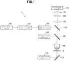
- a pulse laser apparatus 101 emits, for example, ultrashort pulse light with a near infrared wavelength (about 1000 nm) and a pulse width of femtoseconds (e.g., 100 femtoseconds).
- the ultrashort pulse light immediately after being emitted from the pulse laser apparatus 101 is generally linearly-polarized light polarized in a predetermined direction.
- a beam adjuster 103 has: a function to adjust a beam diameter of the ultrashort pulse light incident from the pulse divider 102 in accordance with a pupil diameter of the objective lens 106; a function to condense the ultrashort pulse light and adjust a divergence angle of the ultrashort pulse light in order to correct an axial chromatic aberration (focus difference) between a wavelength of multi-photon excitation light emitted from a specimen S and a wavelength of the ultrashort pulse light; and a pre-chirp function (group velocity dispersion compensation function) to impart reverse group velocity dispersion to the ultrashort pulse light in order to correct a pulse width of the ultrashort pulse light from being widened due to group velocity dispersion while the ultrashort pulse light passes through the optical system.
- group velocity dispersion compensation function group velocity dispersion compensation function
- the repetition frequency of the ultrashort pulse light emitted from the pulse laser apparatus 101 is increased by the pulse divider 102, and the above-described adjustment is performed by the beam adjuster 103. Then, the ultrashort pulse light emitted from the beam adjuster 103 is reflected by a dichroic mirror 104 in a direction to a dichroic mirror 105, passes through the dichroic mirror 105, is condensed by the objective lens 106, and emitted to the specimen S. At this point, an observation surface of the specimen S may be scanned with the ultrashort pulse light by using a scanning unit (not shown).
- the observation light emitted from the specimen S in the direction of the objective lens 106 is collimated by the objective lens 106, and then reflected by the dichroic mirror 105 or passes through the dichroic mirror 105 depending on the wavelength of the observation light.
- the observation light reflected by the dichroic mirror 105 is incident on a fluorescence detector 107.
- the fluorescence detector 107 includes, for example, a barrier filter, a photo multiplier tube (PMT), and the like, receives the observation light reflected by the dichroic mirror 105, and outputs an electric signal corresponding to a light amount thereof. Furthermore, the fluorescence detector 107 detects the observation light over the observation surface of the specimen S when the observation surface of the specimen S is scanned with the ultrashort pulse light.
- descanning is performed by the scanning unit (not shown) for the observation light that has passed through the dichroic mirror 105, and the observation light passes through the dichroic mirror 104, is collected by the condenser lens 108, passes through a pinhole 109 provided at a position substantially conjugate to a focal position of the objective lens 106, passes through the image-forming lens 110, and is incident on a fluorescence detector 111.
- the fluorescence detector 111 includes, for example, a barrier filter, a PMT, and the like, receives the observation light imaged by the image-forming lens 110 on a light receiving surface of the fluorescence detector 111, and outputs an electric signal corresponding to a light amount thereof. Furthermore, the fluorescence detector 111 detects the observation light over the observation surface of the specimen S when the observation surface of the specimen S is scanned with the ultrashort pulse light.
- all of the observation light emitted from the specimen S in the direction of the objective lens 106 may be detected by the fluorescence detector 111 by removing the dichroic mirror 105 from an optical path.
- the observation light emitted from the specimen S in a direction opposite to the objective lens 106 is reflected by a dichroic mirror 112 and incident on a fluorescence detector 113.
- the fluorescence detector 113 includes, for example, a barrier filter, a PMT, and the like, receives the observation light reflected by the dichroic mirror 112, and outputs an electric signal corresponding to a light amount thereof. Furthermore, the fluorescence detector 113 detects the observation light over the observation surface of the specimen S when the observation surface of the specimen S is scanned with the ultrashort pulse light.
- the electric signals output from the fluorescence detectors 107, 111 and 113 respectively are received in, for example, a computer (not shown), and the computer can generate an observation image on the basis of the received electric signals, display the generated observation image, and store data of the observation image.
- the optical glass of the present embodiment can be manufactured by using, for example, a levitation furnace.
- a levitation furnace there are: an electrostatic type; an electromagnetic type; a sonic type; a magnetic type; a gas-jet type; and the like, and the type is not particularly limited, however; it is preferable to use a gas-jet levitation furnace for levitation melting of an oxide.
- a manufacturing method using the gas-jet levitation furnace will be described below as an example.
- FIGS. 3A and 3B show schematic views of a gas-jet levitation furnace.
- FIG. 3A is the schematic view of an entire structure of the levitation furnace
- FIG. 3B is the enlarged schematic view of a base on a stage of the gas-jet levitation furnace.
- a raw material M is placed on a base 302 on a stage 301. Then, the raw material M is irradiated with laser light L emitted from a laser light source 303 via a mirror 304 and a mirror 305. A temperature of the raw material M heated by the irradiation with the laser light L is monitored by a radiation thermometer 306.
- Output of the laser light source 303 is controlled by a computer 307 on the basis of temperature information of the raw material M monitored by the radiation thermometer 306. Furthermore, a state of the raw material M is imaged by a CCD camera 308 and output to a monitor 309 (see FIG. 3A ). Note that a carbon dioxide laser can be used as the laser light source, for example.
- the raw material M is in a state of being levitated by a gas fed into the base (see FIG. 3B ).
- a flow rate of the gas fed into the base is controlled by a gas flow rate regulator 310.
- the gas can be jetted from a nozzle provided with a conical hole, and non-contact heating can be performed by a laser beam L in a state where the raw material M is levitated.
- a shape of the material becomes spherical or ellipsoidal due to own surface tension and is levitated in this state.
- the laser beam L intercepted, the raw material that has become a state of a melt is cooled, and a transparent glass is obtained.
- a kind of the gas is not particularly limited, and a known gas can be appropriately adopted, and oxygen, nitrogen, carbon dioxide, argon, air, or the like can be exemplified. Additionally, a shape of the nozzle and the heating method are not particularly limited, and a known method can be appropriately adopted.
- a La 3+ -Ga 3+ system that is basic composition of the optical glass according to the present embodiment is hardly vitrified.
- a container such as a crucible that is normally used
- crystallization starts from an interface between the container and the melt (heterogeneous nucleation) and vitrification is difficult in most cases.
- the optical glass according to the present embodiment has a high n d , a high Abbe number, and high optical transmitting property for the light in a broad band approximately from 270 nm to 10 ⁇ m. Therefore, the optical glass is applicable as a glass material with a high refractive index and low dispersion or a material with broad band light transmission. Furthermore, since a third component such as Nb 5+ is combined with the two-component La 3+ -Ga 3+ system, a region of a higher refractive index can also be covered without seriously impairing transmissivity of the above-described component system for the broad light region (however, the action and effect of the present embodiment are not limited thereto).
- Optical glass was prepared in accordance with following procedures by using the gas-jet levitation furnace 3 shown in FIGS. 3A and 3B .
- the mixed raw material was uniaxially pressurized at 20 MPa and shaped into cylindrical pellets.
- the obtained pellets were fired in the air by an electric furnace at 1000 to 1300°C for 6 to 12 hours to prepare a sintered body.
- the obtained sintered body was coarsely crushed, and several tens of milligrams thereof were sampled and set at the nozzle of the base.
- the raw material was melted by emitting carbonic dioxide laser beams from above while injecting an oxygen gas.
- the melted raw material came to have a spherical or ellipsoidal shape due to own surface tension, and was brought into a levitated state by pressure of the gas.
- the raw material was cooled by intercepting output of the laser beams in a state where the raw material was completely melted, and then the glass was obtained. Note that a transparent glass sphere having a diameter of 2 to 3 mm was obtained in each of Examples. Additionally, in the glass of each of Examples, volatilization that could be visually recognized was not observed during melting, and the glass was obtained without bubbles and devitrification.
- UV-Visible/NIR Spectrophotometer (“UH4150” manufactured by Hitachi High-Technologies Corporation) was used to measure transmissivity for the light in the range from the ultraviolet region to the visible region. Two surfaces of the glass sphere were polished so as to form flat parallel faces with a thickness of 1 mm, and the processed specimen was fixed at an aperture provided with a hole of a diameter of 2.0 mm, and transmissivity was measured for the light in the range from 250 to 700 nm.
- FT-IR Fourier transform infrared
- NICOLET 6700 manufactured by Thermo Fisher
- a refractive index of the glass was measured by using a prism coupler (model "2010/M” manufactured by Metricon).
- the polished faces of the specimen used in the above-described transmissivity measurement was brought into tight contact with a single crystal rutile prism, and a refractive index was acquired by measuring a total reflection angle when light having a measurement wavelength was incident. Measurement was executed five times at three wavelengths of 473 nm, 594.1 nm, and 656 nm, and an average value was adopted as a measured value.
- n 2 ⁇ 1 ⁇ m c 2 e 2 Nf 1 ⁇ 0 2 ⁇ 1 ⁇ 2 n: refractive index
- m electron mass
- c light velocity
- e elementary charge
- N number of molecules per unit volume
- f oscillator strength
- ⁇ 0 natural resonance wavelength
- ⁇ wavelength
- composition of the components (mass% basis), a specimen thickness, an ultraviolet absorption edge wavelength (UV ⁇ 5 ), an infrared absorption edge wavelength (IR ⁇ 5 ), a refractive index (n d ), and an Abbe number ( ⁇ d ) are shown respectively in each of Tables.
- EXAMPLE 1 EXAMPLE 2 EXAMPLE 3 EXAMPLE 4 EXAMPLE 5 EXAMPLE 6 EXAMPLE 7 EXAMPLE 8 EXAMPLE 9 EXAMPLE 10 La 3+ 55 50 45 40 35 30 25 60 60 55 Ga 3+ 45 50 55 60 65 70 75 15 10 40 Nb 5+ 25 30 5 B 3+ Si 4+ Ge 4+ Al 3+ Ti 4+ Zr 4+ Hf 4+ Ta 5+ W 6+ Y 3+ Gd 3+ Lu 3+ Mg 2+ Ca 2+ Sr 2+ Ba 2+ Zn 2+ Total 100 100 100 100 100 100 100 100 100 100 100 100 100 100 100 100 100 100 100 100 100 100 100 100 100 100 100 100 100 100 100 100 100 100 100 100 100 100 100 100 100 100 100 100 100 100 100 100 100 100 100 100 100 100 100 100 100 100 100 100 100 100 100 100 100 100 100 100 100 100 100 100 100 100 100 100 100 100 100 100 100 100 100 100 100 100 100 100 100 100 100 100 100 100 100 100 100 100 100 100 100 100 100 100 100 100 100 100 100 100 100 100
- the optical glass in all of Examples had the refractive index (n d ) of 1.85 to 2.25, the ultraviolet absorption edge wavelength (UV ⁇ 5 ) of 370 nm or less, the infrared absorption edge wavelength (IR ⁇ 5 ) of 6 ⁇ m or more, and the optical glass exhibited excellent transmissivity for the light from the ultraviolet to the mid-infrared while having the high refractive index.
Landscapes
- Chemical & Material Sciences (AREA)
- Engineering & Computer Science (AREA)
- Materials Engineering (AREA)
- Organic Chemistry (AREA)
- Chemical Kinetics & Catalysis (AREA)
- Geochemistry & Mineralogy (AREA)
- General Chemical & Material Sciences (AREA)
- Life Sciences & Earth Sciences (AREA)
- Physics & Mathematics (AREA)
- General Physics & Mathematics (AREA)
- Optics & Photonics (AREA)
- Manufacturing & Machinery (AREA)
- Glass Compositions (AREA)
Abstract
Description
- The present invention relates to optical glass, an optical element including the optical glass, and an optical apparatus. The present invention claims the priority of Japanese Patent Application No.
2016-165366 filed August 26, 2016 - Optical glass is used in various kinds of optical elements and optical apparatuses, and for example,
JP 07-081973 A - In a first aspect of the present invention, provided is optical glass containing, in terms of mol% of cations: 10 to 60% of a La3+ component; more than 0% and up to 75% of a Ga3+ component; and 5 to 75% of a Nb5+ component, in which a total amount of the La3+ component, Ga3+ component, and Nb5+ component is 60 to 100%.
- In a second aspect of the present invention, provided is an optical element including the optical glass of the first aspect.
- In a third aspect of the present invention, provided is an optical apparatus including the optical element of the second aspect.
-
-
FIG. 1 is a block diagram showing an exemplary configuration of a multi-photon microscope including an optical element using optical glass according to an embodiment of the present invention; -
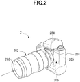
FIG. 2 is a perspective view of an imaging apparatus including an optical element using optical glass according to an embodiment of the present invention; -
FIG. 3A is a diagram showing a schematic view of an entire structure of a gas-jet levitation furnace; and -
FIG. 3B is an enlarged schematic view of a base on a stage of the gas-jet levitation furnace. - An embodiment of the present invention (hereinafter referred to as "the present embodiment") will be described below. The present embodiment described below is an example to describe the present invention and is not intended to limit the present invention to the following matters.
- A range of composition and a range of characteristics of each of components of optical glass in the present embodiment are as described below. Note that, in the present specification, the content of every one of components is indicated in terms of mol% of cations unless otherwise particularly specified.
- In the optical glass according to the present embodiment, following relations are satisfied in terms of mol% of cations: a La3+ component is 10 to 60%; a Ga3+ component is more than 0% and up to 75%; a Nb5+ component is 5 to 75%; and a total amount of the La3+ component, Ga3+ component, and Nb5+ component is 60 to 100%. A form of each of the cations is not particularly limited, but each of the cations is contained in the optical glass in a form of, for example, an oxide described later. As far as these relations are satisfied, the content of Nb5+ may be 0%. The optical glass according to the present embodiment is novel optical glass that can be vitrified even when the content of cations constituting a network-forming oxide such as SiO2 or B2O3 is low. Furthermore, optical glass having a high refractive index and a broad transmission band for a light range from ultraviolet to mid-infrared can be obtained. Generally, the optical glass can hardly achieve both a high refractive index and transmissivity for the light range from the ultraviolet region to a visible region, and both of them tend to have a trade-off relation. From this fact, it is difficult to obtain optical glass having a high refractive index and being colorless and transparent in the visible region. However, in the optical glass according to the present embodiment, these characteristics can also be provided by having the above-described composition of the components.
- La3+ is an essential component in the optical glass according to the present embodiment and contained as La2O3 in terms of oxide composition. La3+ is effective as a component to increase a refractive index and improve ultraviolet transmitting property and infrared transmissivity, however; the effect is not sufficient when the content is little. On the other hand, when the content of La3+ exceeds 60%, the glass tends to be devitrified. Therefore, the content is 10 to 60%, preferably 30 to 60%, and more preferably 40 to 55%.
- Ga3+ is an essential component in the optical glass according to the present embodiment and contained as Ga2O3 in terms of oxide composition. Ga3+ has an effect of improving the ultraviolet transmissivity and the infrared transmissivity, but the effect is not sufficient when the content is little. On the other hand, when Ga3+ is excessively introduced, the refractive index is decreased. Therefore, the content is more than 0 and to 75% (more than 0% and up to 75% or less), preferably 10 to 70% (10% or more and 70% or less), and more preferably 20 to 60% (20% or more and 60% or less).
- Nb5+ is an optional component in the optical glass according to the present embodiment and contained as Nb2O5 in terms of oxide composition. Nb5+ has a significant effect of increasing the refractive index of the glass, and stability of the glass can be further enhanced by introducing Nb5+ as a glass component together with La3+ and Ga3+. On the other hand, when Nb5+ is excessively introduced, the ultraviolet transmissivity is largely degraded. Therefore, the content is 0 to 75%, preferably 5 to 60%, and more preferably 10 to 50%.
- Other components that can be contained in the optical glass according to the present embodiment include, for example, Ti4+, Zr4+, Hf4+, Ta5+, W6+, Al3+, B3+, Si4+, Ge4+, Zn2+, Y3+, Gd3+, Lu3+, Mg2+, Ca2+, Sr2+, and Ba2+. A form of each of the cations is not particularly limited, but each of the cations is contained in the optical glass in a form of, for example, an oxide described later. Needless to mention, not only one kind but also two or more kinds of cations may be introduced. These optional components will be described below.
- Ti4+ is a component contained as TiO2 in terms of oxide composition. Ti4+ has an effect of increasing the refractive index of the glass, however; when the content is much, the ultraviolet transmissivity is largely degraded. Therefore, the content is preferably 0 to 30%, more preferably 0 to 20%, and still more preferably 0 to 10%.
- Zr4+ and Hf4+ are components contained as ZrO2 and HfO2 respectively in terms of oxide composition. Zr4+ and Hf4+ do not largely degrade the ultraviolet transmissivity and have an effect of increasing the refractive index of the glass, however; when the content is much, the glass tends to be devitrified. Therefore, the content is preferably 0 to 30%, more preferably 5 to 25%, and still more preferably from 5 to 20%.
- Ta5+ is a component contained as Ta2O5 in terms of oxide composition. Ta5+ has an effect of increasing the refractive index and improving the ultraviolet transmissivity and the infrared transmissivity, however; when Ta5+ is excessively introduced, the glass is likely to be crystallized. Therefore, the content is preferably 0 to 30%, more preferably 5 to 25%, and still more preferably 10 to 20%.
- W6+ is a component contained as WO3 in terms of oxide composition. W6+ has an effect of increasing the refractive index, but is a component that degrades the ultraviolet transmissivity and infrared transmissivity of the glass. Therefore, the content is preferably 0 to 20%, more preferably 0 to 10%, and still more preferably 0 to 5%.
- Al3+ is a component contained as Al2O3 in terms of oxide composition. Al3+ has an effect of stabilizing the glass and improving the ultraviolet transmissivity, however; when Al3+ is excessively introduced, the refractive index is decreased. Therefore, the content is preferably 0 to 30%, more preferably 0 to 20%, and still more preferably 0 to 15%.
- B3+ is contained as B2O3 in terms of oxide composition and is a component constituting a network forming oxide. B3+ has an effect of improving glass formability, however; since B3+ is a component with high volatility, B3+ tends to deteriorate quality of striae when B3+ is excessively introduced. Also, B3+ is component that degrades the infrared transmissivity. Therefore, the content is preferably 0 to 30%, more preferably 0 to 20%, and still more preferably 0 to 10%, and still furthermore preferably 0%. Even when the content of B3+ constituting the network forming oxide is reduced to this extent, the optical glass according to the present embodiment can be vitrified and can provide an excellent physical property.
- Si4+ is contained as SiO2 in terms of oxide composition and also is a component constituting a network forming oxide. Si4+ has an effect of easily improving glass formability, however; Si4+ largely decreases the refractive index and the infrared transmissivity. Therefore, the content is preferably 0 to 20%, more preferably 0 to 15%, still more preferably 0 to 10%, and still furthermore preferably 0%. Even when the content of Si4+ constituting a network forming oxide is reduced to this extent, the optical glass according to the present embodiment can be vitrified and can provide an excellent physical property.
- Ge4+ is contained as GeO2 in terms of oxide composition and is a component constituting a network forming oxide. Ge4+ has an effect of easily improving glass formability, however; a raw material is expensive. Additionally, when Ge4+ is excessively introduced, volatility is exhibited and the quality of striae of the glass is deteriorated. Therefore, the content is preferably 0 to 20%, more preferably 0 to 15%, still more preferably 0 to 10%, and still furthermore preferably 0%. Even when the content of Ge4+ is reduced to this extent, the optical glass according to the present embodiment can be vitrified and can provide an excellent physical property.
- Zn2+ is a component contained as ZnO in terms of oxide composition. Zn2+ has an effect similar to the above-mentioned Ln3+ component does, however; since the effect of increasing the refractive index is lower than of that of the Ln3+ component, a high refractive index is impaired when Zn2+ is excessively introduced. Also, when Zn2+ is excessively introduced, volatility is exhibited and the quality of striae of the glass is deteriorated. Therefore, the content is preferably 0 to 20%, more preferably 0 to 15%, and still more preferably 0 to 10%.
- Rare earth Ln3+ (representing one or more of Ln = Y, Gd, and Lu) is a component contained as Ln2O3 in terms of oxide composition. Similar to La3+, Ln3+ has an effect of increasing the refractive index and improving the ultraviolet transmissivity and the infrared transmissivity, however; when Ln3+ is excessively introduced, the glass tends to be devitrified. Therefore, a total amount of the Ln3+ component is preferably 0 to 30%, more preferably 0 to 25%, and still more preferably 0 to 20%.
- An alkaline earth metal oxide R2+ (representing one or more of R = Mg, Ca, Sr, and Ba) is a component contained as RO in terms of oxide composition. R2+ has an effect similar to the above-described Ln3+ component, however; since the effect of increasing the refractive index is lower than that of the Ln3+ component, the property of high refractive index is impaired when R2+ is excessively introduced. Therefore, a total amount of the R2+ component is preferably 0 to 20%, more preferably 0 to 15%, and still more preferably 0 to 10%.
- In the optical glass according to the present embodiment, the total amount of the La3+ component, Ga3+ component, and Nb5+ component satisfies a relation of 60 to 100%. The total amount of the La3+ component, Ga3+ component, and Nb5+ component is preferably 80 to 100%, more preferably 90 to 100%, and still more preferably 95 to 100%. When the above-described conditions are satisfied, it is possible to improve the transmissivity for the light from ultraviolet to infrared, the refractive index, and economic efficiency of the optical glass.
- In the optical glass according to the present embodiment, a preferable combination of the above optional components preferably satisfies following respective relations in terms of mol% of cations: the B3+ component is 0 to 30%, Si4+ component is 0 to 20%, the Ge4+ component is 0 to 20%; and a total amount of the B3+ component, Si4+ component, and Ge4+ component is 0 to 30%.
- Furthermore, in the optical glass according to the present embodiment, the total amount of the B3+ component, Si4+component, and Ge4+ component may also be 0%. In other words, B3+, Si4+ and Ge4+ may not be substantially contained. The optical glass according to the present embodiment can be vitrified without containing these components constituting the network forming oxides. Additionally, since Ge4+ is especially the expensive component, economic efficiency can be improved by not substantially containing B3+, Si4+ and Ge4+.
- In the optical glass according to the present embodiment, a preferable combination of the above optional components satisfies following respective relations in terms of mol% of cations: the Ti4+ component is 0 to 30%, the Zr4+ component is 0 to 20%, the Hf4+ component is 0 to 20%, the Ta5+ component is 0 to 30%, the W6+ component is 0 to 20%, the Al3+ component is 0 to 30%, the B3+ component is 0 to 30%, the Si4+ component is 0 to 20%, the Ge4+ component is 0 to 20%, the Zn2+ component is 0 to 20%, a total amount of the Ln3+ component (representing one or more of Ln = Y, Gd, and Lu) is 0 to 30%, and a total amount of R2+ component (representing one or more of R = Mg, Ca, Sr, and Ba) is 0 to 20%. A form of each of the cations is not particularly limited, but each of the cations is contained in the optical glass in a form of, for example, an oxide. The transmissivity and the refractive index of the optical glass are further improved by having the combination in the above-described composition of the components.
- Not limited to the above-described components, other optional components may also be further added within a range not affecting achievement of the object of the optical glass according to the present embodiment.
- Next, physical property values of the optical glass of the present embodiment will be described.
- The optical glass according to the present embodiment relates to the optical glass with a high refractive index region. A refractive index (nd) of the optical glass of the present embodiment in a d-line (wavelength: 587.562 nm) is preferably 1.85 to 2.25, more preferably 1.88 to 2.25, and still more preferably 1.92 to 2.25.
- Furthermore, the optical glass according to the present embodiment is glass with low dispersion (a high Abbe number (νd)). The Abbe number (νd) of the optical glass according to the present embodiment is preferably 19 to 37, more preferably 25 to 36, and still more preferably 30 to 35.
- To achieve wide utility for the light from the ultraviolet to the mid-infrared, it is desirable that: an ultraviolet absorption edge wavelength of the glass be on a short wavelength side as much as possible; and an infrared absorption edge wavelength be on a long wavelength side as much as possible. In this respect, the optical glass according to the present embodiment can preferably have a wavelength (UVλ5) of 370 nm or less, more preferably 330 nm or less, and still more preferably 300 nm or less as a wavelength at which an ultraviolet transmissivity value including a surface reflection loss becomes 5% under the condition of a thickness of 1mm. Furthermore, it is possible to have a wavelength (IRλ5) of 6µm or more, more preferably 6.5 µm or more, and still more preferably 7 µm or more as a wavelength at which an infrared transmissivity value including a surface reflection loss becomes 5% under the condition of a thickness of 1mm. Note that the absorption edge wavelengths described in the present specification represent the above-described UVλ5 and IRλ5.
- The optical glass according to the present embodiment is the glass with a high refractive index, which exhibits excellent transmissivity for the light range from the ultraviolet region to the infrared region. For example, in an optical system using the above-described optical glass in combination with another optical glass, it is possible to widen a degree of freedom in optical design more than that in the related art.
- The optical glass according to the present embodiment is preferable as an optical element like a lens included in an optical apparatus such as a camera or a microscope. As the optical apparatus, a multi-photon microscope is particularly preferable.
-
FIG. 1 is a block diagram showing an exemplary configuration of a multi-photon microscope 1 that is an embodiment of the present invention. The multi-photon microscope 1 includes, as optical elements, anobjective lens 106, acondenser lens 108, and an image-forminglens 110. An optical system of the multi-photon microscope 1 will be mainly described below. - A
pulse laser apparatus 101 emits, for example, ultrashort pulse light with a near infrared wavelength (about 1000 nm) and a pulse width of femtoseconds (e.g., 100 femtoseconds). The ultrashort pulse light immediately after being emitted from thepulse laser apparatus 101 is generally linearly-polarized light polarized in a predetermined direction. - A
pulse divider 102 divides the ultrashort pulse light and emits the ultrashort pulse light while increasing a repetition frequency thereof. - A
beam adjuster 103 has: a function to adjust a beam diameter of the ultrashort pulse light incident from thepulse divider 102 in accordance with a pupil diameter of theobjective lens 106; a function to condense the ultrashort pulse light and adjust a divergence angle of the ultrashort pulse light in order to correct an axial chromatic aberration (focus difference) between a wavelength of multi-photon excitation light emitted from a specimen S and a wavelength of the ultrashort pulse light; and a pre-chirp function (group velocity dispersion compensation function) to impart reverse group velocity dispersion to the ultrashort pulse light in order to correct a pulse width of the ultrashort pulse light from being widened due to group velocity dispersion while the ultrashort pulse light passes through the optical system. - The repetition frequency of the ultrashort pulse light emitted from the
pulse laser apparatus 101 is increased by thepulse divider 102, and the above-described adjustment is performed by thebeam adjuster 103. Then, the ultrashort pulse light emitted from thebeam adjuster 103 is reflected by adichroic mirror 104 in a direction to adichroic mirror 105, passes through thedichroic mirror 105, is condensed by theobjective lens 106, and emitted to the specimen S. At this point, an observation surface of the specimen S may be scanned with the ultrashort pulse light by using a scanning unit (not shown). - For example, when the specimen S is observed with fluorescence, fluorescent pigment with which the specimen S is colored is subjected to multi-photon excitation in a region of the specimen S irradiated with the ultrashort pulse light as well as in the vicinity of this region, and fluorescence having a wavelength shorter than that of the ultrashort pulse light, namely, the infrared wavelength is emitted (hereinafter referred to as "observation light").
- The observation light emitted from the specimen S in the direction of the
objective lens 106 is collimated by theobjective lens 106, and then reflected by thedichroic mirror 105 or passes through thedichroic mirror 105 depending on the wavelength of the observation light. - The observation light reflected by the
dichroic mirror 105 is incident on afluorescence detector 107. Thefluorescence detector 107 includes, for example, a barrier filter, a photo multiplier tube (PMT), and the like, receives the observation light reflected by thedichroic mirror 105, and outputs an electric signal corresponding to a light amount thereof. Furthermore, thefluorescence detector 107 detects the observation light over the observation surface of the specimen S when the observation surface of the specimen S is scanned with the ultrashort pulse light. - On the other hand, descanning is performed by the scanning unit (not shown) for the observation light that has passed through the
dichroic mirror 105, and the observation light passes through thedichroic mirror 104, is collected by thecondenser lens 108, passes through apinhole 109 provided at a position substantially conjugate to a focal position of theobjective lens 106, passes through the image-forminglens 110, and is incident on afluorescence detector 111. Thefluorescence detector 111 includes, for example, a barrier filter, a PMT, and the like, receives the observation light imaged by the image-forminglens 110 on a light receiving surface of thefluorescence detector 111, and outputs an electric signal corresponding to a light amount thereof. Furthermore, thefluorescence detector 111 detects the observation light over the observation surface of the specimen S when the observation surface of the specimen S is scanned with the ultrashort pulse light. - Meanwhile, all of the observation light emitted from the specimen S in the direction of the
objective lens 106 may be detected by thefluorescence detector 111 by removing thedichroic mirror 105 from an optical path. - Also, the observation light emitted from the specimen S in a direction opposite to the
objective lens 106 is reflected by adichroic mirror 112 and incident on afluorescence detector 113. Thefluorescence detector 113 includes, for example, a barrier filter, a PMT, and the like, receives the observation light reflected by thedichroic mirror 112, and outputs an electric signal corresponding to a light amount thereof. Furthermore, thefluorescence detector 113 detects the observation light over the observation surface of the specimen S when the observation surface of the specimen S is scanned with the ultrashort pulse light. - The electric signals output from the
fluorescence detectors - An optical element using the optical glass according to the present embodiment can also be used in an imaging apparatus.
FIG. 2 is a perspective view of an imaging apparatus including an optical element using the optical glass according to an embodiment of the present invention. The imaging apparatus 2 (optical apparatus) includes a lens 203 (optical element) in which the optical glass according to the present embodiment is adopted as a base material. - The
imaging apparatus 2 is a so-called digital single-lens reflex camera, and alens barrel 202 is detachably attached to a lens mount (not shown) of acamera body 201. Light having passed through alens 203 of thelens barrel 202 is formed as an image on a sensor chip (solid-state imaging element) 204 of amulti-chip module 206 arranged on a rear side of thecamera body 201. Thissensor chip 204 is a bare chip such as a so-called CMOS image sensor. Themulti-chip module 206 is, for example, a chip on glass (COG) type module in which thesensor chip 204 is mounted on aglass substrate 205 in a bare chip state. - Note that the optical apparatus is not limited to such an imaging apparatus and includes a variety of apparatuses like a projector. The optical element is also not limited to a lens and includes, for example, a variety of elements such as a prism.
- The optical glass of the present embodiment can be manufactured by using, for example, a levitation furnace. As the levitation furnace, there are: an electrostatic type; an electromagnetic type; a sonic type; a magnetic type; a gas-jet type; and the like, and the type is not particularly limited, however; it is preferable to use a gas-jet levitation furnace for levitation melting of an oxide. A manufacturing method using the gas-jet levitation furnace will be described below as an example.
-
FIGS. 3A and3B show schematic views of a gas-jet levitation furnace. In the drawings,FIG. 3A is the schematic view of an entire structure of the levitation furnace, andFIG. 3B is the enlarged schematic view of a base on a stage of the gas-jet levitation furnace. In the gas-jet levitation furnace 3, a raw material M is placed on a base 302 on astage 301. Then, the raw material M is irradiated with laser light L emitted from alaser light source 303 via amirror 304 and amirror 305. A temperature of the raw material M heated by the irradiation with the laser light L is monitored by aradiation thermometer 306. Output of thelaser light source 303 is controlled by acomputer 307 on the basis of temperature information of the raw material M monitored by theradiation thermometer 306. Furthermore, a state of the raw material M is imaged by aCCD camera 308 and output to a monitor 309 (seeFIG. 3A ). Note that a carbon dioxide laser can be used as the laser light source, for example. - In the gas-
jet levitation furnace 3, the raw material M is in a state of being levitated by a gas fed into the base (seeFIG. 3B ). A flow rate of the gas fed into the base is controlled by a gasflow rate regulator 310. For example, the gas can be jetted from a nozzle provided with a conical hole, and non-contact heating can be performed by a laser beam L in a state where the raw material M is levitated. When the raw material M is melted, a shape of the material becomes spherical or ellipsoidal due to own surface tension and is levitated in this state. After that, when the laser beam L is intercepted, the raw material that has become a state of a melt is cooled, and a transparent glass is obtained. Note that a kind of the gas is not particularly limited, and a known gas can be appropriately adopted, and oxygen, nitrogen, carbon dioxide, argon, air, or the like can be exemplified. Additionally, a shape of the nozzle and the heating method are not particularly limited, and a known method can be appropriately adopted. - Conventionally, a La3+-Ga3+ system that is basic composition of the optical glass according to the present embodiment is hardly vitrified. For example, in a case of manufacturing optical glass by using a container such as a crucible that is normally used, it is necessary to improve glass formability by containing a large amount of network forming oxides such as SiO2, B2O3, P2O5, and GeO2 In a case of the composition having little content of the network forming oxides with low glass formability, crystallization starts from an interface between the container and the melt (heterogeneous nucleation) and vitrification is difficult in most cases.
- On the other hand, in a case of manufacturing the optical glass by the above-described method using the levitation furnace, there is no contact between the container and the melt, and therefore, heterogeneous nucleation can be suppressed to a maximum extent. As a result, vitrification of the melt can be greatly promoted and vitrification can be achieved even in a case of having the composition with which manufacturing by the crucible melting is impossible and in which little content of network forming oxides is contained or no network forming oxide is contained. With adoption of the above-described manufacturing method, it is possible to manufacture the optical glass of the La3+-Ga3+ system that cannot be vitrified in the related art. The optical glass according to the present embodiment has a high nd, a high Abbe number, and high optical transmitting property for the light in a broad band approximately from 270 nm to 10 µm. Therefore, the optical glass is applicable as a glass material with a high refractive index and low dispersion or a material with broad band light transmission. Furthermore, since a third component such as Nb5+ is combined with the two-component La3+-Ga3+ system, a region of a higher refractive index can also be covered without seriously impairing transmissivity of the above-described component system for the broad light region (however, the action and effect of the present embodiment are not limited thereto).
- The present invention will be described more in detail using following Examples and Comparative Examples, but the present invention is not limited by the following Examples.
- Optical glass was prepared in accordance with following procedures by using the gas-
jet levitation furnace 3 shown inFIGS. 3A and3B . First, raw materials selected from oxides, hydroxides, carbonates, nitrates, sulfates, and the like were weighed so as to obtain predetermined chemical composition, and then mixed in an alumina mortar. The mixed raw material was uniaxially pressurized at 20 MPa and shaped into cylindrical pellets. The obtained pellets were fired in the air by an electric furnace at 1000 to 1300°C for 6 to 12 hours to prepare a sintered body. The obtained sintered body was coarsely crushed, and several tens of milligrams thereof were sampled and set at the nozzle of the base. Then, the raw material was melted by emitting carbonic dioxide laser beams from above while injecting an oxygen gas. The melted raw material came to have a spherical or ellipsoidal shape due to own surface tension, and was brought into a levitated state by pressure of the gas. The raw material was cooled by intercepting output of the laser beams in a state where the raw material was completely melted, and then the glass was obtained. Note that a transparent glass sphere having a diameter of 2 to 3 mm was obtained in each of Examples. Additionally, in the glass of each of Examples, volatilization that could be visually recognized was not observed during melting, and the glass was obtained without bubbles and devitrification. - An UV-Visible/NIR Spectrophotometer ("UH4150" manufactured by Hitachi High-Technologies Corporation) was used to measure transmissivity for the light in the range from the ultraviolet region to the visible region. Two surfaces of the glass sphere were polished so as to form flat parallel faces with a thickness of 1 mm, and the processed specimen was fixed at an aperture provided with a hole of a diameter of 2.0 mm, and transmissivity was measured for the light in the range from 250 to 700 nm.
- A Fourier transform infrared (FT-IR) spectrophotometer ("NICOLET 6700" manufactured by Thermo Fisher) was used to measure infrared transmissivity. Similar to measurement of transmissivity for ultraviolet to visible light, the transmissivity was measured in a range from 400 to 4000 cm-1 by using an aperture with a diameter of 2.0 mm.
- A refractive index of the glass was measured by using a prism coupler (model "2010/M" manufactured by Metricon). The polished faces of the specimen used in the above-described transmissivity measurement was brought into tight contact with a single crystal rutile prism, and a refractive index was acquired by measuring a total reflection angle when light having a measurement wavelength was incident. Measurement was executed five times at three wavelengths of 473 nm, 594.1 nm, and 656 nm, and an average value was adopted as a measured value. Additionally, for the provided measured value, fitting was performed by a least-square method using a Drude-Voigt dispersion equation shown below to calculate a refractive index and an Abbe number (νd) in each of a d-line (587.562 nm), an F-line (486.133 nm), and a C-line (656.273 nm).

- Additionally, the Abbe number (νd) is defined by an Equation below.

- As for optical glass in each of Examples and each of Comparative Examples, composition of the components (mass% basis), a specimen thickness, an ultraviolet absorption edge wavelength (UVλ5), an infrared absorption edge wavelength (IRλ5), a refractive index (nd), and an Abbe number (νd) are shown respectively in each of Tables.
[Table 1] EXAMPLE 1 EXAMPLE 2 EXAMPLE 3 EXAMPLE 4 EXAMPLE 5 EXAMPLE 6 EXAMPLE 7 EXAMPLE 8 EXAMPLE 9 EXAMPLE 10 La3+ 55 50 45 40 35 30 25 60 60 55 Ga3+ 45 50 55 60 65 70 75 15 10 40 Nb5+ 25 30 5 B3+ Si4+ Ge4+ Al3+ Ti4+ Zr4+ Hf4+ Ta5+ W6+ Y3+ Gd3+ Lu3+ Mg2+ Ca2+ Sr2+ Ba2+ Zn2+ Total 100 100 100 100 100 100 100 100 100 100 VITRIFICATION ○ ○ ○ ○ ○ ○ ○ ○ ○ ○ UV λ 5(nm) 274 281 277 278 282 286 289 316 322 301 IR λ 5 (µm) 8.38 7.58 8.06 7.97 7.90 7.65 7.69 7.44 706 7.76 nd 1.96183 1.95368 1.94806 1.94771 1.93512 1.92851 1.92161 2.10192 2.12566 1.99055 ν d 34.3 33.6 34.0 34.7 33.6 33.6 34.6 27.6 27.0 32.2 [Table 2] EXAMPLE 11 EXAMPLE 12 EXAMPLE 13 EXAMPLE 14 EXAMPLE 15 EXAMPLE 16 EXAMPLE 17 EXAMPLE 18 EXAMPLE 19 EXAMPLE 20 La3+ 55 55 55 55 50 50 50 40 40 40 Ga3+ 35 30 25 20 40 30 20 50 40 30 Nb5+ 10 15 20 25 10 20 30 10 20 30 B3+ Si4+ Ge4+ Al3+ Ti4+ Zr4+ Hf4+ Ta5+ W6+ Y3+ Gd3+ Lu3+ Mg2+ Ca2+ Sr2+ Ba2+ Zn2+ Total 100 100 100 100 100 100 100 100 100 100 VITRIFICATION ○ ○ ○ ○ ○ ○ ○ ○ ○ ○ UV λ 5(nm) 306 310 314 317 307 314 323 307 317 326 IR λ 5(µm) 7.64 7.56 7.46 7.34 7.48 7.21 6.96 7.31 7.20 6.80 nd 2.01952 2.04528 2.07086 2.09497 2.01905 2.06478 2.11349 2.00786 2.05451 2.10232 ν d 31.1 29.5 28.8 27.9 30.7 28.7 27.2 30.8 28.7 26.9 [Table 3] EXAMPLE 21 EXAMPLE 22 EXAMPLE 23 EXAMPLE 24 EXAMPLE 25 EXAMPLE 26 EXAMPLE 27 EXAMPLE 28 EXAMPLE 29 EXAMPLE 30 La3+ 40 40 30 30 30 30 30 30 20 20 Ga3+ 20 10 60 50 40 30 20 10 30 20 Nb5+ 40 50 10 20 30 40 50 60 50 60 B3+ Si4+ Ge4+ Al3+ Ti4+ Zr4+ Hf4+ Ta5+ W6+ Y3+ Gd3+ Lu3+ Mg2+ Ca2+ Sr2+ Ba2+ Zn2+ Total 100 100 100 100 100 100 100 100 100 100 VITRIFICATION ○ ○ ○ ○ ○ ○ ○ ○ ○ ○ UV λ5(nm) 332 342 304 315 324 332 342 347 351 359 IR λ5(µm) 6.78 6.45 7.48 7.33 7.19 7.04 6.45 6.78 6.70 6.61 nd 2.14495 2.18276 1.98507 2.03847 2.09007 2.12886 2.16991 2.21373 2.15838 2.20384 ν d 25.2 23.8 30.7 28.6 26.4 24.7 23.1 21.6 22.3 20.8 [Table 4] EXAMPLE 31 EXAMPLE 32 EXAMPLE 33 EXAMPLE 34 EXAMPLE 35 EXAMPLE 36 EXAMPLE 37 EXAMPLE 38 EXAMPLE 39 EXAMPLE 40 La3+ 20 10 30 30 30 30 30 30 55 30 Ga3+ 10 30 65 60 65 60 65 60 35 60 Nb5+ 70 60 B3+ 5 10 Si4+ 5 10 Ge4+ 5 10 Al3+ 10 Ti4+ 10 Zr4+ Hf4+ Ta5+ W6+ Y3+ Gd3+ Lu3+ Mg2+ Ca2+ Sr2+ Ba2+ Zn2+ Total 100 100 100 100 100 100 100 100 100 100 VITRIFICATION ○ ○ ○ ○ ○ ○ ○ ○ ○ ○ UV λ 5(nm) 365 363 284 282 281 279 286 286 272 328 IR λ 5(µm) 6.54 6.63 6.90 6.47 7.38 7.10 7.48 7.43 7.40 7.29 nd 2.24826 2.18795 1.92761 1.91967 1.90537 1.88538 1.92858 1.93319 1.94163 1.98842 ν d 19.3 19.9 34.7 35.7 35.3 36.9 34.3 34.0 34.7 30.3 [Table 5] EXAMPLE 41 EXAMPLE 42 EXAMPLE 43 EXAMPLE 44 EXAMPLE 45 EXAMPLE 46 EXAMPLE 47 EXAMPLE 48 EXAMPLE 49 EXAMPLE 50 La3+ 30 30 55 55 45 45 45 50 45 45 Ga3+ 60 60 35 35 45 45 45 45 45 45 Nb5+ B3+ Si4+ Ge4+ Al3+ Ti4+ Zr4+ 10 Hf4+ 10 Ta5+ 10 W6+ 10 Y3+ 10 Gd3+ 10 Lu3+ 10 Mg2+ 5 Ca2+ 10 Sr2+ 10 Ba2+ Zn2+ Total 100 100 100 100 100 100 100 100 100 100 VITRIFICATION ○ ○ ○ ○ ○ ○ ○ ○ ○ ○ UV λ 5(nm) 278 279 270 350 276 278 278 276 279 280 IR λ 5(µm) 7.53 7.53 7.64 7.44 7.73 7.73 7.71 7.83 7.66 7.68 nd 1.96295 1.95337 2.00278 2.02550 1.95512 1.96209 1.95955 1.95226 1.92822 1.92665 ν d 33.6 34.9 32.7 28.9 34.0 33.8 34.2 33.8 34.0 32.8 [Table 6] EXAMPLE 51 EXAMPLE 52 La3+ 45 45 Ga3+ 45 45 Nb5+ B 3+ Si4+ Ge4+ Al3+ Ti4+ Zr4+ Hf4+ Ta5+ W6+ Y3+ Gd3+ Lu3+ Mg2+ Ca2+ Sr2+ Ba2+ 10 Zn2+ 10 Total 100 100 VITRIFICATION ○ ○ UV λ 5(nm) 280 278 IR λ 5(µm) 7.72 7.65 nd 1.92758 1.95550 ν d 33.3 34.7 - Kinds of optical glass each having different composition of the components shown in each of Tables 7 to 9 were prepared by a method similar to Examples described above. However, crystallization was observed in a part or an entire part of each specimen, and it was impossible to obtain a specimen usable as optical glass.
[Table 7] COMP.EX.1 COMP.EX.2 COMP.EX. 3 COMP.EX. 4 COMP.EX. 5 COMP.EX. 6 COMP.EX. 7 COMP.EX. 8 COMP.EX. 9 COMP.EX 10 La3+ 90 85 80 75 70 65 20 15 70 70 Ga3+ 10 15 20 25 30 35 80 85 10 20 Nb5+ 20 10 B3+ Si4+ Ge4+ Al3+ Ti4+ Zr4+ Hf4+ Ta5+ W6+ Y3+ Gd3+ Lu3+ Mg2+ Ca2+ Sr2+ Ba2+ Zn2+ Total 100 100 100 100 100 100 100 100 100 100 VITRIFICATION × × × × × × × × × × UV λ5(nm) IR λ5(µm) nd ν d [Table 8] COMP.EX.11 COMP.EX.12 COMP.EX.13 COMP.EX.14 COMP.EX.15 COMP.EX.16 COMP.EX.17 COMP.EX.18 COMP.EX.19 COMP.EX. 20 La3+ 65 65 65 10 10 Ga3+ 5 10 15 10 80 20 25 30 35 40 Nb5+ 30 25 20 80 10 80 75 70 65 60 B3+ Si4+ Ge4+ Al3+ Ti4+ Zr4+ Hf4+ Ta5+ W6+ Y3+ Gd3+ Lu3+ Mg2+ Ca2+ Sr2+ Ba2+ Zn2+ Total 100 100 100 100 100 100 100 100 100 100 VITRIFICATION × × × × × × × × × × UV λ 5(nm) IR λ 5(µm) nd ν4 [Table 9] COMP.EX. 21 COMP.EX. 22 COMP.EX.23 COMP.EX. 24 COMP.EX.25 COMP.EX. 26 La3+ Ga3+ 45 50 55 60 65 70 Nb5+ 55 50 45 40 35 30 B3+ Si4+ Ge4+ Al3+ Ti4+ Zr4+ Hf4+ Ta5+ W6+ Y3+ Gd3+ Lu3+ Mg2+ Ca2+ Sr2+ Ba2+ Zn2+ Total 100 100 100 100 100 100 VITRIFICATION × × × × × × UV λ 5(nm) IR λ 5(µ m) nd ν d - From the above, it was confirmed that the optical glass in all of Examples had the refractive index (nd) of 1.85 to 2.25, the ultraviolet absorption edge wavelength (UVλ5) of 370 nm or less, the infrared absorption edge wavelength (IRλ5) of 6 µm or more, and the optical glass exhibited excellent transmissivity for the light from the ultraviolet to the mid-infrared while having the high refractive index.
Claims (11)
- Optical glass containing, in terms of mol% of cations:10 to 60% of a La3+ component;more than 0% and up to 75% of a Ga3+ component; and5 to 75% of a Nb5+ component,wherein a total amount of the La3+ component, the Ga3+ component, and the Nb5+ component is 60 to 100%.
- The optical glass according to claim 1, further containing at least one component selected from a group consisting of Ti4+, Zr4+, Hf4+, Ta5+, W6+, Al3+, B3+, Si4+, Ge4+, Zn2+, Y3+, Gd3+, Lu3+, Mg2+, Ca2+, Sr2+, and Ba2+.
- The optical glass according to claim 1 or 2, containing, in terms of mol% of cations:0 to 30% of a B3+ component;0 to 20% of a Si4+ component; and0 to 20% of a Ge4+ component,wherein a total amount of the B3+ component, the Si4+ component, and the Ge4+ component is 0 to 30%.
- The optical glass according to claim 1 or 2, wherein the total amount of the B3+ component, the Si4+ component, and the Ge4+ component is 0%.
- The optical glass according to any one of claims 1 to 4, containing, in terms of mol% of cations:0 to 30% of a Ti4+ component;0 to 20% of a Zr4+ component;0 to 20% of a Hf4+ component;0 to 30% of a Ta5+ component;0 to 20% of a W6+ component;0 to 30% of Al3+ component; and0 to 20% of Zn2+ component,wherein a total amount of a Ln3+ component (representing one or more of Ln = Y, Gd, and Lu) is 0 to 30%, and a total amount of a R2+ component (representing one or more of R = Mg, Ca, Sr, and Ba) is 0 to 20%.
- The optical glass according to any one of claims 1 to 5, wherein a refractive index (nd) in a d-line is 1.85 to 2.25.
- The optical glass according to any one of claims 1 to 6, wherein an Abbe number (νd) is 19 to 37.
- The optical glass according to any one of claims 1 to 7,
wherein a wavelength (UVλ5) at which an ultraviolet transmittance value including a surface reflection loss becomes 5% under a condition of a thickness of 1 mm is 370 nm or less. - The optical glass according to any one of claims 1 to 8,
wherein a wavelength (IRλ5) at which an infrared transmittance value including a surface reflection loss becomes 5% under the condition of the thickness of 1 mm is 6 µm or more. - An optical element comprising the optical glass according to any one of claims 1 to 9.
- An optical apparatus comprising the optical element according to claim 10.
Applications Claiming Priority (2)
| Application Number | Priority Date | Filing Date | Title |
|---|---|---|---|
| JP2016165366 | 2016-08-26 | ||
| PCT/JP2017/026520 WO2018037797A1 (en) | 2016-08-26 | 2017-07-21 | Optical glass, optical element formed of optical glass, and optical device |
Publications (3)
| Publication Number | Publication Date |
|---|---|
| EP3505499A1 true EP3505499A1 (en) | 2019-07-03 |
| EP3505499A4 EP3505499A4 (en) | 2020-04-15 |
| EP3505499B1 EP3505499B1 (en) | 2023-12-13 |
Family
ID=61246523
Family Applications (1)
| Application Number | Title | Priority Date | Filing Date |
|---|---|---|---|
| EP17843283.7A Active EP3505499B1 (en) | 2016-08-26 | 2017-07-21 | Optical glass, optical element formed of optical glass, and optical device |
Country Status (5)
| Country | Link |
|---|---|
| US (2) | US11236009B2 (en) |
| EP (1) | EP3505499B1 (en) |
| JP (2) | JP7142572B2 (en) |
| CN (2) | CN114605069B (en) |
| WO (1) | WO2018037797A1 (en) |
Families Citing this family (6)
| Publication number | Priority date | Publication date | Assignee | Title |
|---|---|---|---|---|
| CN111108074B (en) | 2017-09-21 | 2022-07-01 | 株式会社尼康 | Optical glass, optical element comprising optical glass, optical system, interchangeable lens, and optical device |
| JP7076981B2 (en) * | 2017-10-25 | 2022-05-30 | キヤノン株式会社 | Manufacturing method of optical glass, optical element, optical equipment and optical glass |
| EP3949794A4 (en) * | 2019-04-05 | 2022-12-21 | Nippon Electric Glass Co., Ltd. | DECORATIVE GLASS ARTICLE |
| JP7378985B2 (en) * | 2019-07-02 | 2023-11-14 | 株式会社オハラ | Optical glass, preforms and optical elements |
| JP7712599B2 (en) * | 2020-05-15 | 2025-07-24 | 日本電気硝子株式会社 | Glass Material |
| CN119907780A (en) * | 2022-09-30 | 2025-04-29 | 株式会社 尼康 | Optical glass, optical elements, optical systems, cemented lenses, microscope objectives, interchangeable lenses for cameras, and optical devices |
Family Cites Families (22)
| Publication number | Priority date | Publication date | Assignee | Title |
|---|---|---|---|---|
| US5232879A (en) * | 1992-08-06 | 1993-08-03 | Corning Incorporated | Alkali metal lanthanum gallate glasses |
| JPH0781973A (en) | 1993-09-14 | 1995-03-28 | Yamamura Glass Co Ltd | Halide glass |
| US5392376A (en) * | 1994-04-11 | 1995-02-21 | Corning Incorporated | Gallium sulfide glasses |
| JP3301034B2 (en) | 1995-05-17 | 2002-07-15 | 日本電信電話株式会社 | Glass composition |
| US7141522B2 (en) * | 2003-09-18 | 2006-11-28 | 3M Innovative Properties Company | Ceramics comprising Al2O3, Y2O3, ZrO2 and/or HfO2, and Nb2O5 and/or Ta2O5 and methods of making the same |
| JP2005154251A (en) | 2003-10-30 | 2005-06-16 | Asahi Glass Co Ltd | Optical glass and lens |
| JP4359169B2 (en) | 2004-03-24 | 2009-11-04 | Hoya株式会社 | Press molding preform manufacturing method, manufacturing apparatus, and optical element manufacturing method |
| JP2006131450A (en) * | 2004-11-05 | 2006-05-25 | Asahi Glass Co Ltd | Optical glass and lens |
| JP4743681B2 (en) * | 2004-11-11 | 2011-08-10 | Hoya株式会社 | OPTICAL GLASS, GLASS MATERIAL FOR PRESS MOLDING AND ITS MANUFACTURING METHOD, OPTICAL COMPONENT AND ITS MANUFACTURING METHOD |
| JP4522392B2 (en) * | 2006-06-16 | 2010-08-11 | Hoya株式会社 | Optical glass and optical product using the same |
| CN101495419A (en) * | 2006-08-01 | 2009-07-29 | 佳能株式会社 | Optical glass and optical device |
| JP5450937B2 (en) | 2006-08-01 | 2014-03-26 | キヤノン株式会社 | Optical glass and optical element |
| JP4953234B2 (en) * | 2006-09-14 | 2012-06-13 | 独立行政法人 宇宙航空研究開発機構 | Titanium-based oxide glass and method for producing the same |
| JP5174368B2 (en) * | 2007-04-03 | 2013-04-03 | 株式会社オハラ | Optical glass |
| US8053384B2 (en) | 2007-04-03 | 2011-11-08 | Ohara Inc. | Optical glass |
| JP5602987B2 (en) | 2007-10-12 | 2014-10-08 | 株式会社オハラ | Optical glass |
| JP5863227B2 (en) * | 2009-09-30 | 2016-02-16 | 株式会社オハラ | Glass member for optical component, method for producing optical component, and glass composition for optical component |
| TWI594966B (en) * | 2010-10-08 | 2017-08-11 | Ohara Kk | Optical glass, preform and optical element |
| CN103313947A (en) * | 2011-01-18 | 2013-09-18 | 株式会社小原 | Optical glass, preforms and optical components |
| JP5767179B2 (en) * | 2012-08-30 | 2015-08-19 | 株式会社オハラ | Optical glass, preform and optical element |
| CN104341000B (en) * | 2013-08-05 | 2017-09-29 | 北京化工大学 | The preparation method and purposes of mixed nanometer group vib metal oxide particle or its dispersion |
| US11236099B2 (en) * | 2017-06-20 | 2022-02-01 | Takeda Pharmaceutical Company Limited | Heterocyclic compound |
-
2017
- 2017-07-21 EP EP17843283.7A patent/EP3505499B1/en active Active
- 2017-07-21 JP JP2018535535A patent/JP7142572B2/en active Active
- 2017-07-21 WO PCT/JP2017/026520 patent/WO2018037797A1/en not_active Ceased
- 2017-07-21 CN CN202210393403.1A patent/CN114605069B/en active Active
- 2017-07-21 CN CN201780049727.0A patent/CN109562980B/en active Active
-
2019
- 2019-02-22 US US16/283,349 patent/US11236009B2/en active Active
-
2021
- 2021-12-28 US US17/563,760 patent/US12319616B2/en active Active
-
2022
- 2022-04-07 JP JP2022063843A patent/JP2022106744A/en active Pending
Also Published As
| Publication number | Publication date |
|---|---|
| US11236009B2 (en) | 2022-02-01 |
| CN109562980B (en) | 2022-05-06 |
| JP2022106744A (en) | 2022-07-20 |
| CN109562980A (en) | 2019-04-02 |
| WO2018037797A1 (en) | 2018-03-01 |
| EP3505499A4 (en) | 2020-04-15 |
| CN114605069A (en) | 2022-06-10 |
| US20190185369A1 (en) | 2019-06-20 |
| JPWO2018037797A1 (en) | 2019-06-20 |
| EP3505499B1 (en) | 2023-12-13 |
| US20220119302A1 (en) | 2022-04-21 |
| CN114605069B (en) | 2024-06-11 |
| JP7142572B2 (en) | 2022-09-27 |
| US12319616B2 (en) | 2025-06-03 |
Similar Documents
| Publication | Publication Date | Title |
|---|---|---|
| US12319616B2 (en) | Optical glass, optical element including optical glass, and optical apparatus | |
| US12466759B2 (en) | Optical glass, optical element composed of optical glass, optical system interchangeable lens, and optical device | |
| EP3702336B1 (en) | Optical glass, and optical element, cemented lens, optical system, interchangeable lens for camera and optical device using same | |
| EP4365144A1 (en) | Optical glass, optical element, optical system, cemented lens, interchangeable lens for cameras, objective lens for microscopes, and optical device | |
| US20220162112A1 (en) | Optical glass, optical element, optical system, interchangeable lens, and optical device | |
| CN110650927A (en) | Optical glass, optical element using same, optical system, cemented lens, interchangeable lens for camera, and optical device | |
| US20250250191A1 (en) | Optical glass, optical element, optical system, cemented lens, microscope objective lens, interchangeable camera lens, and optical device | |
| CN113165954A (en) | Optical glass, optical element, optical system, interchangeable lens, and optical device | |
| EP4245736A1 (en) | Optical glass, optical element, optical system, cemented lens, interchangable lens for camera, objective lens for microscope, and optical device | |
| EP3385233B1 (en) | Optical glass, optical element using optical glass, and optical device | |
| JP2020200204A (en) | Optical glass, optical element including optical glass, optical system, interchangeable lens, and an optical device | |
| WO2025135173A1 (en) | Optical glass, optical element, optical system, objective lens for microscope, interchangeable lens for camera, endoscopic instrument, and optical device | |
| WO2025134659A1 (en) | Optical glass, optical element, optical system, cemented lens, objective lens for microscope, interchangeable camera lens, and optical device | |
| WO2025142288A1 (en) | Optical glass, optical element, optical system, cemented lens, objective lens for microscope, interchangeable lens for camera, endoscope device and optical device | |
| US20080144167A1 (en) | Optical imaging system and method for high speed and high resolution |
Legal Events
| Date | Code | Title | Description |
|---|---|---|---|
| STAA | Information on the status of an ep patent application or granted ep patent |
Free format text: STATUS: THE INTERNATIONAL PUBLICATION HAS BEEN MADE |
|
| PUAI | Public reference made under article 153(3) epc to a published international application that has entered the european phase |
Free format text: ORIGINAL CODE: 0009012 |
|
| STAA | Information on the status of an ep patent application or granted ep patent |
Free format text: STATUS: REQUEST FOR EXAMINATION WAS MADE |
|
| 17P | Request for examination filed |
Effective date: 20190225 |
|
| AK | Designated contracting states |
Kind code of ref document: A1 Designated state(s): AL AT BE BG CH CY CZ DE DK EE ES FI FR GB GR HR HU IE IS IT LI LT LU LV MC MK MT NL NO PL PT RO RS SE SI SK SM TR |
|
| AX | Request for extension of the european patent |
Extension state: BA ME |
|
| DAV | Request for validation of the european patent (deleted) | ||
| DAX | Request for extension of the european patent (deleted) | ||
| A4 | Supplementary search report drawn up and despatched |
Effective date: 20200317 |
|
| RIC1 | Information provided on ipc code assigned before grant |
Ipc: C03C 4/10 20060101ALI20200311BHEP Ipc: C03C 3/12 20060101ALI20200311BHEP Ipc: C03C 3/062 20060101ALI20200311BHEP Ipc: C03C 3/253 20060101ALI20200311BHEP Ipc: C03B 1/00 20060101ALI20200311BHEP Ipc: C03C 3/15 20060101AFI20200311BHEP Ipc: C03C 3/068 20060101ALI20200311BHEP Ipc: C03C 3/155 20060101ALI20200311BHEP Ipc: C03C 4/00 20060101ALI20200311BHEP Ipc: G02B 1/00 20060101ALI20200311BHEP |
|
| GRAP | Despatch of communication of intention to grant a patent |
Free format text: ORIGINAL CODE: EPIDOSNIGR1 |
|
| STAA | Information on the status of an ep patent application or granted ep patent |
Free format text: STATUS: GRANT OF PATENT IS INTENDED |
|
| INTG | Intention to grant announced |
Effective date: 20230803 |
|
| P01 | Opt-out of the competence of the unified patent court (upc) registered |
Effective date: 20230821 |
|
| GRAS | Grant fee paid |
Free format text: ORIGINAL CODE: EPIDOSNIGR3 |
|
| GRAA | (expected) grant |
Free format text: ORIGINAL CODE: 0009210 |
|
| STAA | Information on the status of an ep patent application or granted ep patent |
Free format text: STATUS: THE PATENT HAS BEEN GRANTED |
|
| AK | Designated contracting states |
Kind code of ref document: B1 Designated state(s): AL AT BE BG CH CY CZ DE DK EE ES FI FR GB GR HR HU IE IS IT LI LT LU LV MC MK MT NL NO PL PT RO RS SE SI SK SM TR |
|
| REG | Reference to a national code |
Ref country code: GB Ref legal event code: FG4D |
|
| REG | Reference to a national code |
Ref country code: CH Ref legal event code: EP |
|
| REG | Reference to a national code |
Ref country code: DE Ref legal event code: R096 Ref document number: 602017077537 Country of ref document: DE |
|
| REG | Reference to a national code |
Ref country code: IE Ref legal event code: FG4D |
|
| PG25 | Lapsed in a contracting state [announced via postgrant information from national office to epo] |
Ref country code: GR Free format text: LAPSE BECAUSE OF FAILURE TO SUBMIT A TRANSLATION OF THE DESCRIPTION OR TO PAY THE FEE WITHIN THE PRESCRIBED TIME-LIMIT Effective date: 20240314 |
|
| REG | Reference to a national code |
Ref country code: LT Ref legal event code: MG9D |
|
| PG25 | Lapsed in a contracting state [announced via postgrant information from national office to epo] |
Ref country code: LT Free format text: LAPSE BECAUSE OF FAILURE TO SUBMIT A TRANSLATION OF THE DESCRIPTION OR TO PAY THE FEE WITHIN THE PRESCRIBED TIME-LIMIT Effective date: 20231213 |
|
| REG | Reference to a national code |
Ref country code: NL Ref legal event code: MP Effective date: 20231213 |
|
| PG25 | Lapsed in a contracting state [announced via postgrant information from national office to epo] |
Ref country code: ES Free format text: LAPSE BECAUSE OF FAILURE TO SUBMIT A TRANSLATION OF THE DESCRIPTION OR TO PAY THE FEE WITHIN THE PRESCRIBED TIME-LIMIT Effective date: 20231213 |
|
| PG25 | Lapsed in a contracting state [announced via postgrant information from national office to epo] |
Ref country code: LT Free format text: LAPSE BECAUSE OF FAILURE TO SUBMIT A TRANSLATION OF THE DESCRIPTION OR TO PAY THE FEE WITHIN THE PRESCRIBED TIME-LIMIT Effective date: 20231213 Ref country code: GR Free format text: LAPSE BECAUSE OF FAILURE TO SUBMIT A TRANSLATION OF THE DESCRIPTION OR TO PAY THE FEE WITHIN THE PRESCRIBED TIME-LIMIT Effective date: 20240314 Ref country code: ES Free format text: LAPSE BECAUSE OF FAILURE TO SUBMIT A TRANSLATION OF THE DESCRIPTION OR TO PAY THE FEE WITHIN THE PRESCRIBED TIME-LIMIT Effective date: 20231213 Ref country code: BG Free format text: LAPSE BECAUSE OF FAILURE TO SUBMIT A TRANSLATION OF THE DESCRIPTION OR TO PAY THE FEE WITHIN THE PRESCRIBED TIME-LIMIT Effective date: 20240313 |
|
| REG | Reference to a national code |
Ref country code: AT Ref legal event code: MK05 Ref document number: 1640328 Country of ref document: AT Kind code of ref document: T Effective date: 20231213 |
|
| PG25 | Lapsed in a contracting state [announced via postgrant information from national office to epo] |
Ref country code: NL Free format text: LAPSE BECAUSE OF FAILURE TO SUBMIT A TRANSLATION OF THE DESCRIPTION OR TO PAY THE FEE WITHIN THE PRESCRIBED TIME-LIMIT Effective date: 20231213 |
|
| PG25 | Lapsed in a contracting state [announced via postgrant information from national office to epo] |
Ref country code: SE Free format text: LAPSE BECAUSE OF FAILURE TO SUBMIT A TRANSLATION OF THE DESCRIPTION OR TO PAY THE FEE WITHIN THE PRESCRIBED TIME-LIMIT Effective date: 20231213 Ref country code: RS Free format text: LAPSE BECAUSE OF FAILURE TO SUBMIT A TRANSLATION OF THE DESCRIPTION OR TO PAY THE FEE WITHIN THE PRESCRIBED TIME-LIMIT Effective date: 20231213 Ref country code: NO Free format text: LAPSE BECAUSE OF FAILURE TO SUBMIT A TRANSLATION OF THE DESCRIPTION OR TO PAY THE FEE WITHIN THE PRESCRIBED TIME-LIMIT Effective date: 20240313 Ref country code: NL Free format text: LAPSE BECAUSE OF FAILURE TO SUBMIT A TRANSLATION OF THE DESCRIPTION OR TO PAY THE FEE WITHIN THE PRESCRIBED TIME-LIMIT Effective date: 20231213 Ref country code: LV Free format text: LAPSE BECAUSE OF FAILURE TO SUBMIT A TRANSLATION OF THE DESCRIPTION OR TO PAY THE FEE WITHIN THE PRESCRIBED TIME-LIMIT Effective date: 20231213 Ref country code: HR Free format text: LAPSE BECAUSE OF FAILURE TO SUBMIT A TRANSLATION OF THE DESCRIPTION OR TO PAY THE FEE WITHIN THE PRESCRIBED TIME-LIMIT Effective date: 20231213 |
|
| PG25 | Lapsed in a contracting state [announced via postgrant information from national office to epo] |
Ref country code: IS Free format text: LAPSE BECAUSE OF FAILURE TO SUBMIT A TRANSLATION OF THE DESCRIPTION OR TO PAY THE FEE WITHIN THE PRESCRIBED TIME-LIMIT Effective date: 20240413 |
|
| PG25 | Lapsed in a contracting state [announced via postgrant information from national office to epo] |
Ref country code: AT Free format text: LAPSE BECAUSE OF FAILURE TO SUBMIT A TRANSLATION OF THE DESCRIPTION OR TO PAY THE FEE WITHIN THE PRESCRIBED TIME-LIMIT Effective date: 20231213 Ref country code: CZ Free format text: LAPSE BECAUSE OF FAILURE TO SUBMIT A TRANSLATION OF THE DESCRIPTION OR TO PAY THE FEE WITHIN THE PRESCRIBED TIME-LIMIT Effective date: 20231213 |
|
| PG25 | Lapsed in a contracting state [announced via postgrant information from national office to epo] |
Ref country code: SK Free format text: LAPSE BECAUSE OF FAILURE TO SUBMIT A TRANSLATION OF THE DESCRIPTION OR TO PAY THE FEE WITHIN THE PRESCRIBED TIME-LIMIT Effective date: 20231213 |
|
| PG25 | Lapsed in a contracting state [announced via postgrant information from national office to epo] |
Ref country code: SM Free format text: LAPSE BECAUSE OF FAILURE TO SUBMIT A TRANSLATION OF THE DESCRIPTION OR TO PAY THE FEE WITHIN THE PRESCRIBED TIME-LIMIT Effective date: 20231213 Ref country code: SK Free format text: LAPSE BECAUSE OF FAILURE TO SUBMIT A TRANSLATION OF THE DESCRIPTION OR TO PAY THE FEE WITHIN THE PRESCRIBED TIME-LIMIT Effective date: 20231213 Ref country code: RO Free format text: LAPSE BECAUSE OF FAILURE TO SUBMIT A TRANSLATION OF THE DESCRIPTION OR TO PAY THE FEE WITHIN THE PRESCRIBED TIME-LIMIT Effective date: 20231213 Ref country code: IT Free format text: LAPSE BECAUSE OF FAILURE TO SUBMIT A TRANSLATION OF THE DESCRIPTION OR TO PAY THE FEE WITHIN THE PRESCRIBED TIME-LIMIT Effective date: 20231213 Ref country code: IS Free format text: LAPSE BECAUSE OF FAILURE TO SUBMIT A TRANSLATION OF THE DESCRIPTION OR TO PAY THE FEE WITHIN THE PRESCRIBED TIME-LIMIT Effective date: 20240413 Ref country code: EE Free format text: LAPSE BECAUSE OF FAILURE TO SUBMIT A TRANSLATION OF THE DESCRIPTION OR TO PAY THE FEE WITHIN THE PRESCRIBED TIME-LIMIT Effective date: 20231213 Ref country code: CZ Free format text: LAPSE BECAUSE OF FAILURE TO SUBMIT A TRANSLATION OF THE DESCRIPTION OR TO PAY THE FEE WITHIN THE PRESCRIBED TIME-LIMIT Effective date: 20231213 Ref country code: AT Free format text: LAPSE BECAUSE OF FAILURE TO SUBMIT A TRANSLATION OF THE DESCRIPTION OR TO PAY THE FEE WITHIN THE PRESCRIBED TIME-LIMIT Effective date: 20231213 |
|
| PG25 | Lapsed in a contracting state [announced via postgrant information from national office to epo] |
Ref country code: PT Free format text: LAPSE BECAUSE OF FAILURE TO SUBMIT A TRANSLATION OF THE DESCRIPTION OR TO PAY THE FEE WITHIN THE PRESCRIBED TIME-LIMIT Effective date: 20240415 Ref country code: PL Free format text: LAPSE BECAUSE OF FAILURE TO SUBMIT A TRANSLATION OF THE DESCRIPTION OR TO PAY THE FEE WITHIN THE PRESCRIBED TIME-LIMIT Effective date: 20231213 |
|
| PG25 | Lapsed in a contracting state [announced via postgrant information from national office to epo] |
Ref country code: PT Free format text: LAPSE BECAUSE OF FAILURE TO SUBMIT A TRANSLATION OF THE DESCRIPTION OR TO PAY THE FEE WITHIN THE PRESCRIBED TIME-LIMIT Effective date: 20240415 Ref country code: PL Free format text: LAPSE BECAUSE OF FAILURE TO SUBMIT A TRANSLATION OF THE DESCRIPTION OR TO PAY THE FEE WITHIN THE PRESCRIBED TIME-LIMIT Effective date: 20231213 |
|
| REG | Reference to a national code |
Ref country code: DE Ref legal event code: R097 Ref document number: 602017077537 Country of ref document: DE |
|
| PG25 | Lapsed in a contracting state [announced via postgrant information from national office to epo] |
Ref country code: DK Free format text: LAPSE BECAUSE OF FAILURE TO SUBMIT A TRANSLATION OF THE DESCRIPTION OR TO PAY THE FEE WITHIN THE PRESCRIBED TIME-LIMIT Effective date: 20231213 |
|
| PLBE | No opposition filed within time limit |
Free format text: ORIGINAL CODE: 0009261 |
|
| STAA | Information on the status of an ep patent application or granted ep patent |
Free format text: STATUS: NO OPPOSITION FILED WITHIN TIME LIMIT |
|
| PG25 | Lapsed in a contracting state [announced via postgrant information from national office to epo] |
Ref country code: SI Free format text: LAPSE BECAUSE OF FAILURE TO SUBMIT A TRANSLATION OF THE DESCRIPTION OR TO PAY THE FEE WITHIN THE PRESCRIBED TIME-LIMIT Effective date: 20231213 |
|
| PG25 | Lapsed in a contracting state [announced via postgrant information from national office to epo] |
Ref country code: SI Free format text: LAPSE BECAUSE OF FAILURE TO SUBMIT A TRANSLATION OF THE DESCRIPTION OR TO PAY THE FEE WITHIN THE PRESCRIBED TIME-LIMIT Effective date: 20231213 Ref country code: DK Free format text: LAPSE BECAUSE OF FAILURE TO SUBMIT A TRANSLATION OF THE DESCRIPTION OR TO PAY THE FEE WITHIN THE PRESCRIBED TIME-LIMIT Effective date: 20231213 |
|
| 26N | No opposition filed |
Effective date: 20240916 |
|
| PG25 | Lapsed in a contracting state [announced via postgrant information from national office to epo] |
Ref country code: MC Free format text: LAPSE BECAUSE OF FAILURE TO SUBMIT A TRANSLATION OF THE DESCRIPTION OR TO PAY THE FEE WITHIN THE PRESCRIBED TIME-LIMIT Effective date: 20231213 |
|
| REG | Reference to a national code |
Ref country code: CH Ref legal event code: PL |
|
| PG25 | Lapsed in a contracting state [announced via postgrant information from national office to epo] |
Ref country code: LU Free format text: LAPSE BECAUSE OF NON-PAYMENT OF DUE FEES Effective date: 20240721 |
|
| PG25 | Lapsed in a contracting state [announced via postgrant information from national office to epo] |
Ref country code: LU Free format text: LAPSE BECAUSE OF NON-PAYMENT OF DUE FEES Effective date: 20240721 |
|
| PG25 | Lapsed in a contracting state [announced via postgrant information from national office to epo] |
Ref country code: CH Free format text: LAPSE BECAUSE OF NON-PAYMENT OF DUE FEES Effective date: 20240731 Ref country code: BE Free format text: LAPSE BECAUSE OF NON-PAYMENT OF DUE FEES Effective date: 20240731 |
|
| REG | Reference to a national code |
Ref country code: BE Ref legal event code: MM Effective date: 20240731 |
|
| PG25 | Lapsed in a contracting state [announced via postgrant information from national office to epo] |
Ref country code: IE Free format text: LAPSE BECAUSE OF NON-PAYMENT OF DUE FEES Effective date: 20240721 |
|
| PG25 | Lapsed in a contracting state [announced via postgrant information from national office to epo] |
Ref country code: FI Free format text: LAPSE BECAUSE OF FAILURE TO SUBMIT A TRANSLATION OF THE DESCRIPTION OR TO PAY THE FEE WITHIN THE PRESCRIBED TIME-LIMIT Effective date: 20231213 |
|
| PGFP | Annual fee paid to national office [announced via postgrant information from national office to epo] |
Ref country code: DE Payment date: 20250528 Year of fee payment: 9 |
|
| PG25 | Lapsed in a contracting state [announced via postgrant information from national office to epo] |
Ref country code: CY Free format text: LAPSE BECAUSE OF FAILURE TO SUBMIT A TRANSLATION OF THE DESCRIPTION OR TO PAY THE FEE WITHIN THE PRESCRIBED TIME-LIMIT; INVALID AB INITIO Effective date: 20170721 |
|
| PG25 | Lapsed in a contracting state [announced via postgrant information from national office to epo] |
Ref country code: HU Free format text: LAPSE BECAUSE OF FAILURE TO SUBMIT A TRANSLATION OF THE DESCRIPTION OR TO PAY THE FEE WITHIN THE PRESCRIBED TIME-LIMIT; INVALID AB INITIO Effective date: 20170721 |
|
| PG25 | Lapsed in a contracting state [announced via postgrant information from national office to epo] |
Ref country code: TR Free format text: LAPSE BECAUSE OF FAILURE TO SUBMIT A TRANSLATION OF THE DESCRIPTION OR TO PAY THE FEE WITHIN THE PRESCRIBED TIME-LIMIT Effective date: 20231213 |
|
| PGFP | Annual fee paid to national office [announced via postgrant information from national office to epo] |
Ref country code: GB Payment date: 20260601 Year of fee payment: 10 |
|
| PGFP | Annual fee paid to national office [announced via postgrant information from national office to epo] |
Ref country code: FR Payment date: 20260608 Year of fee payment: 10 |