EP3505472A1 - Yarn joining device - Google Patents
Yarn joining device Download PDFInfo
- Publication number
- EP3505472A1 EP3505472A1 EP18214587.0A EP18214587A EP3505472A1 EP 3505472 A1 EP3505472 A1 EP 3505472A1 EP 18214587 A EP18214587 A EP 18214587A EP 3505472 A1 EP3505472 A1 EP 3505472A1
- Authority
- EP
- European Patent Office
- Prior art keywords
- yarn
- guide
- untwisting
- joining device
- pipe
- Prior art date
- Legal status (The legal status is an assumption and is not a legal conclusion. Google has not performed a legal analysis and makes no representation as to the accuracy of the status listed.)
- Granted
Links
Images



Classifications
-
- B—PERFORMING OPERATIONS; TRANSPORTING
- B65—CONVEYING; PACKING; STORING; HANDLING THIN OR FILAMENTARY MATERIAL
- B65H—HANDLING THIN OR FILAMENTARY MATERIAL, e.g. SHEETS, WEBS, CABLES
- B65H69/00—Methods of, or devices for, interconnecting successive lengths of material; Knot-tying devices ;Control of the correct working of the interconnecting device
- B65H69/06—Methods of, or devices for, interconnecting successive lengths of material; Knot-tying devices ;Control of the correct working of the interconnecting device by splicing
- B65H69/061—Methods of, or devices for, interconnecting successive lengths of material; Knot-tying devices ;Control of the correct working of the interconnecting device by splicing using pneumatic means
- B65H69/063—Preparation of the yarn ends
-
- B—PERFORMING OPERATIONS; TRANSPORTING
- B65—CONVEYING; PACKING; STORING; HANDLING THIN OR FILAMENTARY MATERIAL
- B65H—HANDLING THIN OR FILAMENTARY MATERIAL, e.g. SHEETS, WEBS, CABLES
- B65H67/00—Replacing or removing cores, receptacles, or completed packages at paying-out, winding, or depositing stations
- B65H67/08—Automatic end-finding and material-interconnecting arrangements
- B65H67/081—Automatic end-finding and material-interconnecting arrangements acting after interruption of the winding process, e.g. yarn breakage, yarn cut or package replacement
-
- B—PERFORMING OPERATIONS; TRANSPORTING
- B65—CONVEYING; PACKING; STORING; HANDLING THIN OR FILAMENTARY MATERIAL
- B65H—HANDLING THIN OR FILAMENTARY MATERIAL, e.g. SHEETS, WEBS, CABLES
- B65H2701/00—Handled material; Storage means
- B65H2701/30—Handled filamentary material
- B65H2701/31—Textiles threads or artificial strands of filaments
Definitions
- the present invention relates to a yarn joining device that untwists a yarn and then twists and joins the yarn.
- a yarn joining device provided in a yarn winding machine such as a spinning machine and that joins yarn ends of a yarn that has been discontinued for some reason during winding of the yarn is known in the art.
- Japanese Utility Model Laid-Open No. H2-2365 discloses such a yarn joining device.
- Japanese Utility Model Laid-Open No. H2-2365 discloses a yarn joining device including a pair of untwisting pipes and a yarn joining member.
- a pair of slits is formed in an edge of an opening of each of the untwisting pipes.
- the slits are separated by 180 degrees from each other whereby the slits oppose each other.
- Air jetting holes for jetting air in the depth direction of the untwisting pipe are formed inside each of the untwisting pipes.
- the yarn is held by positioning the yarn ends in the slits of the untwisting pipe.
- One object of the present invention is to provide a yarn joining device that prevents failure in the yarn joining of an elastic yarn.
- the yarn joining device includes two untwisting pipes, a yarn joining section, and a yarn guide section corresponding to each of the untwisting pipes.
- the untwisting pipe is configured as a hollow member and the untwisting pipe untwists a yarn end that entered therein by applying air current to the yarn end.
- the yarn joining section has an air chamber in which yarn joining of untwisted yarn ends is performed by applying air current to the yarn ends.
- a guide surface that guides the yarn end pulled out from the corresponding untwisting pipe before the yarn end arrives in the air chamber is formed in the yarn guide section.
- An opening from which the yarn end pulled out from the untwisting pipe is pushed into the air chamber is formed in the yarn joining section.
- the guide surface When seen from a length direction of the untwisting pipe, the guide surface extends from the untwisting pipe and makes a first angle that is larger than zero degrees with respect to an opening surface of the opening. The first angle is smaller than a second angle that an imaginary line connecting a center of the untwisting pipe and an edge of the opening of the yarn joining section that is nearest to the untwisting pipe makes with the opening surface.
- FIG. 1 is a side view indicating an overall configuration of a winder unit 1 including a yarn joining device 41 according to an embodiment of the present invention.
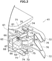
- FIG. 2 is a perspective view of a part of the yarn joining device 41.
- An automatic winder (textile machine) of the present embodiment includes a plurality of winder units 1 shown in FIG. 1 .
- Each winder unit 1 unwinds a yarn 21 from a yarn supplying bobbin 20 and winds the yarn 21 on a winding bobbin 22.
- the winding bobbin 22 with the yarn 21 wound thereon will be called a package 23.
- upstream and downstream respectively refer to the upstream and the downstream in a traveling direction of the yarn 21.
- the winder unit 1 mainly includes a frame 24, a yarn supplying section 25, and a winding section 26.
- the frame 24 is a chassis of the winder unit 1. Majority of the parts of the winder unit 1 are directly or indirectly supported by the frame 24.
- the yarn supplying section 25 holds the yarn supplying bobbin 20 that supplies the yarn 21.
- the yarn supplying section 25 can be, for example, a holding section that holds the yarn supplying bobbin 20 in a substantially upright posture.
- the yarn supplying bobbin 20 can be, for example, the one on which a spandex yarn, in which a yarn having high elasticity made of polyurethane and the like is coated with short fiber of cotton and the like, has been wound.
- the winding section 26 includes a cradle 28 and a winding drum 29.
- the cradle 28 rotatably holds the winding bobbin 22 in a state in which a peripheral surface of the winding bobbin 22 contacts a peripheral surface of the winding drum 29.
- the winding drum 29 is arranged opposed to the winding bobbin 22, and the winding drum 29 is rotationally driven by a not-shown winding-drum driving motor.
- a reciprocating spiral traversing groove is formed on the peripheral surface of the winding drum 29. Because of this traversing groove, the yarn 21 that is wound on the winding bobbin 22 can be traversed.
- the configuration for traversing the yarn 21 is not limited to the winding drum 29 explained above.
- the traversing can be performed by using an arm-type traversing device that includes a traversing guide that reciprocates within a predetermined traversing width and guides the yarn 21.
- a driving force can be applied directly to the winding bobbin 22.
- the winder unit 1 includes, in a yarn traveling path between the yarn supplying section 25 and the winding section 26, an unwinding assisting device 31, a tension applying device 32, and a yarn monitoring device 33 from upstream to downstream of the yarn traveling path in this order.
- the unwinding assisting device 31 includes a regulating member 35 that touches a bulged part (balloon) of the yarn 21 produced because of outward swinging around of the yarn 21 due to a centrifugal force when the yarn 21 is unwound from the yarn supplying bobbin 20. Excessive swinging around of the yarn 21 can be suppressed by touching the regulating member 35 to the balloon. Therefore, by maintaining the size of the balloon to a certain size, the unwinding of the yarn 21 from the yarn supplying bobbin 20 can be performed with a constant tension.
- the tension applying device 32 applies a predetermined tension to the traveling yarn 21.
- the tension applying device 32 is a gate-type member having fixed comb teeth and movable comb teeth. By passing the yarn 21 in a meandering state between the comb teeth that are in an engaged state, an appropriate tension can be applied to the yarn 21 in the tension applying device 32.
- a disk-type tension applying device 32 can be used instead of the gate-type.
- the yarn monitoring device 33 monitors quality of the traveling yarn 21 to detect a yarn defect (portion where there is abnormality) in the yarn 21.
- a not-shown cutter is arranged near the yarn monitoring device 33. The cutter immediately cuts the yarn 21 when the yarn monitoring device 33 detects a yarn defect.
- the winder unit 1 includes the yarn joining device 41, an upper yarn suction pipe 36, and a lower yarn suction pipe 37.
- the yarn joining device 41 joins the yarn 21 from the yarn supplying bobbin 20 and the yarn 21 from the winding bobbin 22.
- the cause of discontinuing the yarn 21 can be cutting of the yarn 21 when a yarn defect is detected by the yarn monitoring device 33, and the like.
- the yarn joining device 41 is positioned between the tension applying device 32 and the yarn monitoring device 33.
- the upper yarn suction pipe 36 is supported by the frame 24 so as to be pivotable up and down.
- the upper yarn suction pipe 36 guides to the yarn joining device 41 the yarn end of the yarn 21 from the winding bobbin 22 that is on the downstream side.
- a suction port is arranged at a tip end part of the upper yarn suction pipe 36.
- the upper yarn suction pipe 36 catches the yarn 21 from the winding bobbin 22 by a suction current generated by a not-shown negative pressure source and guides the caught yarn end of the yarn 21 to the yarn joining device 41.
- the lower yarn suction pipe 37 is supported by the frame 24 so as to be pivotable up and down.
- the lower yarn suction pipe 37 guides to the yarn joining device 41 the yarn end of the yarn 21 from the yarn supplying bobbin 20 that is on the upstream side.
- a suction port is arranged at a tip end part of the lower yarn suction pipe 37.
- the lower yarn suction pipe 37 catches the yarn 21 on the yarn supplying bobbin 20 side by a suction current generated by a not-shown negative pressure source and guides the caught yarn end of the yarn 21 to the yarn joining device 41.
- the yarn joining device 41 is explained in detail below.
- the yarn joining device 41 is configured as a splicer device.
- the yarn joining device 41 generates a swirling current by jetting compressed air and applies the swirling current to the untwisted yarn ends to twist and join the yarn ends.
- the yarn joining device 41 twists the yarn ends by using the force of the air; however, it is allowable to mix an appropriate liquid (e.g., water) with the air in performing the yarn joining.
- an appropriate liquid e.g., water
- it is allowable to heat the air by using an appropriate heater and use the heated air in performing the yarn joining.
- the yarn joining device 41 mainly includes a frame 61, a support plate 68, untwisting pipes 66, a twisting member (yarn joining section) 63, guide plates 71, yarn shifting levers 72, and yarn pressing levers 76.
- the frame 61 is a chassis to which various parts of the yarn joining device 41 are attached.
- the guide plates 71 and the like are fixed to the frame 61.
- the yarn shifting levers 72, the yarn pressing levers 76, and the like are supported by the frame 61.
- a flow path member 62 is fixed to the frame 61.
- a not-shown air flowing path is formed in the flow path member 62.
- the compressed air that is discharged by a not-shown compressed air source, such as a compressor, to perform untwisting and twisting of the yarn ends is circulated in this air flowing path.
- the air flowing path is connected to the two untwisting pipes 66 and the twisting member 63.
- the support plate 68 is a plate-shaped member having a predetermined thickness.
- the support plate 68 is fixed to the flow path member 62.
- the support plate 68 is arranged so as to oppose the yarn traveling path formed in the winder unit 1.
- a pair of the untwisting pipes 66 is arranged on either side of the twisting member 63 in a length direction of the yarn traveling path.
- Each of the untwisting pipes 66 is a narrow cylindrical member with both ends thereof open.
- the length direction of the untwisting pipes 66 is orthogonal to the yarn traveling path.
- a yarn suction port 68A is formed in the support plate 68 at an end near the yarn traveling path.
- a later-explained flexure guide member 81 is attached to this yarn suction port 68A.
- a nozzle hole 66h (see FIG. 3 ) is formed in an inner wall of each of the untwisting pipes 66.
- the nozzle hole 66h is connected to a flow path of the compressed air formed in the flow path member 62.
- An air current that flows toward an opening on the other side of the yarn suction port 68A is generated inside the untwisting pipes 66 when the compressed air is jetted from the nozzle hole 66h.
- the yarn end of the yarn 21, which is guided to the yarn joining device 41 by the upper yarn suction pipe 36 and cut by a later-explained cutter 75 arranged on a lower side is sucked in the untwisting pipe 66 of the lower side and untwisted because of the action of the air current generated in the untwisting pipe 66.
- the yarn end of the yarn 21, which is guided to the yarn joining device 41 by the lower yarn suction pipe 37 and cut by the later-explained cutter 75 arranged on an upper side is sucked in the untwisting pipe 66 of the upper side and untwisted because of the action of the air current generated in the untwisting pipe 66.
- the twisting member 63 is box shaped.
- the twisting member 63 is fixed to the support plate 68 such that the twisting member 63 protrudes from the support plate 68 toward the yarn traveling path.
- a swirling chamber 67 that is long and slender in an up-down direction (that is, a direction that is substantially parallel to the yarn traveling path) and that penetrates through the twisting member 63 is formed in the twisting member 63.
- An end of the swirling chamber 67 in the length direction thereof opens in each of an upper surface and a lower surface of the twisting member 63.
- a twisting guide groove 69 that is open on the yarn traveling path side is formed in the twisting member 63.
- the twisting guide groove 69 communicates to the swirling chamber 67.
- the twisting guide groove 69 is formed in a tapered shape that widens toward the open side thereof. Note that, instead of using the swirling chamber 67, a cylindrical swirling chamber for the lower yarn and a cylindrical swirling chamber for the upper yarn can be provided separately, and the axis of the cylindrical swirling chamber for the lower yarn and the axis of the cylindrical swirling chamber for the upper yarn can be shifted. When this configuration is adopted, interference between swirling air for the lower yarn and swirling air for the upper yarn can be prevented.
- nozzle holes are formed in an inner wall of the swirling chamber 67 for jetting the compressed air inside the swirling chamber 67 to twist the yarn ends.
- the nozzle holes are connected to the flow path of the compressed air formed in the flow path member 62.
- the compressed air is jetted from the nozzle holes to generate the swirling current inside the swirling chamber 67. Because of this swirling current, the yarn ends in the swirling chamber 67 are twisted.
- the swirling chamber 67 in which the air swirls functions as an air chamber 67.
- nozzle holes that generate the swirling air current
- it is allowable to form nozzle holes in the inner wall of the swirling chamber 67 for jetting the air current in crossing directions inside the swirling chamber 67 to twist the yarns by applying impact to the yarns.
- a pair of the guide plates 71 is fixed to the frame 61. Like the pair of the untwisting pipes 66, when the yarn joining device 41 is seen from the yarn traveling path, the pair of the guide plates 71 is arranged on either side of the twisting member 63 in the length direction of the yarn traveling path. A distance between the guide plates 71 and the twisting member 63 is longer than a distance between the untwisting pipes 66 and the twisting member 63.
- Each of the guide grooves 73 is open on the side of the yarn traveling path.
- Each of the guide plates 71 includes a clamp 74 and the cutter 75.
- the clamp 74 can hold the yarn 21 that entered one of the two guide grooves 73.
- the cutter 75 can cut the yarn 21 that entered the other one of the guide grooves 73.
- clamp side guide groove and the other may be referred to as "cutter side guide groove”.
- a clamp cutter having a clamping function can be used as the cutter 75.
- the yarn can be clamped when cutting the yarn, it can be prevented that the cut yarn shrinks and goes away from the untwisting pipe 66.
- the yarn By releasing the clamping in the state that the air current is being applied inside the untwisting pipe 66, the yarn can be surely sucked in the untwisting pipe 66 and the yarn can be untwisted.
- the yarn shifting levers 72 include a pair of arm-shaped members each located on either side of the twisting member 63 in the length direction of the yarn traveling path.
- the two yarn shifting levers 72 rotate integrally with each other. Accordingly, the two yarn shifting levers 72 can move in a pulling direction, in which the yarn is pulled on the side of the yarn joining device 41, and in the opposite direction of the pulling direction.
- An appropriate gap is secured between the support plate 68 and the pair of the guide plates 71. Each of the yarn shifting levers 72 pass through this gap when rotating in the manner explained above.
- the yarn pressing levers 76 include a pair of arm-shaped members each located on either side of the twisting member 63 in the length direction of the yarn traveling path.
- the two yarn pressing levers 76 rotate integrally with each other. Accordingly, the two yarn pressing levers 76 can move in a pressing direction, in which the yarn 21 is pressed toward the support plate 68 (yarn joining device 41), and in the opposite direction of the pressing direction.
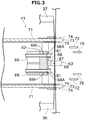
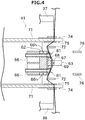
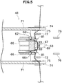
- a yarn joining operation performed by the yarn joining device 41 is explained below by referring to FIGS. 3 to 6 .
- the yarn joining operation performed by the yarn joining device 41 when the yarn 21 is discontinued is shown step by step in FIGS. 3 to 6 .
- the upper yarn suction pipe 36 guides the yarn 21 so that the yarn 21 enters the clamp side guide groove 73 of the upper guide plate 71 and enters the cutter side guide groove 73 of the lower guide plate 71.
- the lower yarn suction pipe 37 guides the yarn 21 so that the yarn 21 enters the clamp side guide groove 73 of the lower guide plate 71 and enters the cutter side guide groove 73 of the upper guide plate 71. Simultaneously with this, the two yarns 21 present between the upper and lower guide plates 71 enter the swirling chamber 67 of the twisting member 63 after passing through the twisting guide groove 69.
- the yarn 21 that is guided by the upper yarn suction pipe 36 is held by the clamp 74 of the upper guide plate 71 and cut by the cutter 75 of the lower guide plate 71.
- the yarn 21 that is guided by the lower yarn suction pipe 37 is held by the clamp 74 of the lower guide plate 71 and cut by the cutter 75 of the upper guide plate 71.
- the unnecessary portions of the yarns 21 can be removed.
- the cut unnecessary portions of the yarns 21 are sucked by the upper yarn suction pipe 36 and the lower yarn suction pipe 37.
- the two yarn shifting levers 72 rotate further as shown in FIG. 6 and enter, while shifting the yarn 21, the gap between the support plate 68 and the pair of the guide plates 71.
- the yarn ends that have entered the untwisting pipes 66 and untwisted are pulled out from the untwisting pipes 66 and inserted into the swirling chamber 67 of the twisting member 63.
- the compressed air is jetted from the nozzle holes of the swirling chamber 67 to twist the two yarn ends and join the yarn ends.
- FIG. 7 is a perspective view of a part of the yarn joining device 41 indicating the flexure guide member 81.
- FIG. 8 is a front view for explaining an angle of a guide groove 84 of the flexure guide member 81 and a contact of the yarns 21 with each other.
- One flexure guide member 81 is arranged at each yarn suction port 68A of each of the two untwisting pipes 66.
- Each of the flexure guide member 81 guides the yarn 21, whose yarn end has been untwisted by the untwisting pipe 66, in the swirling chamber 67 of the twisting member 63.
- the guide groove 84 in which the yarn 21 can enter is formed in the flexure guide member 81. The untwisted yarn 21 is pulled through this guide groove 84 and guided to the swirling chamber 67.
- the flexure guide member 81 is box shaped.
- the flexure guide member 81 is fixed to the support plate 68 such that the flexure guide member 81 protrudes from the support plate 68 toward the yarn traveling path.
- a circular through-hole 82 is formed in the flexure guide member 81. This through-hole 82 constitutes an opening that opens on a surface of the flexure guide member 81 present on the yarn traveling path side.
- the through-hole 82 is provided substantially coaxially with the yarn suction port 68A of the untwisting pipe 66.
- the through-hole 82 is connected to the untwisting pipe 66. Therefore, the untwisting pipe 66 can suck the yarn 21 via the opening of the through-hole 82 by the negative pressure generated because of the air current flowing in the untwisting pipe 66.
- the guide groove 84 that opens on the yarn traveling path side is formed in the flexure guide member 81.
- the guide groove 84 When seen from the length direction of the untwisting pipe 66, the guide groove 84 is formed in a linear shape and connects the inside and the outside of the through-hole 82.
- One of the yarns between the two yarns 21 guided to the yarn joining device 41 is introduced into the guide groove 84 by the yarn end thereof being sucked by the untwisting pipe 66.
- the direction of the guide groove 84 makes an angle ⁇ toward the clamp 74 that clamps the other yarn 21 that is to be joined to the yarn 21 that enters the guide groove 84, with respect to a line that connects a center 66c of the untwisting pipe 66 to a center 67c of an opening surface 67f at which the swirling chamber 67 opens in the surface of the twisting member 63 on the side near the flexure guide member 81.
- the inner wall surface of the wall on the side near the twisting member 63 constitutes a guide surface 83 for guiding the yarn 21.
- the direction of the guide groove 84 and the direction of the guide surface 83 are the same.
- the yarn 21 that entered the guide groove 84 bends at a bending point 21b at an end that is near the swirling chamber 67 among the ends of the guide groove 84 in the length direction of the guide groove 84. Moreover, this end of the guide groove 84 is closer to a path of the other yarn 21 that is to be joined to the yarn 21 that has entered the guide groove 84. Therefore, when each of the yarns 21 have entered the guide groove 84 of the two flexure guide members 81, as shown in FIG. 8 , the two yarns 21 come closer to each other inside as well as near the swirling chamber 67.
- a smoothly curved leading-in guide surface 87 that connects to the guide groove 84 is formed in the flexure guide member 81.
- the leading-in guide surface 87 contacts the yarn 21 sucked in the untwisting pipe 66 (as shown in FIG. 5 )
- the leading-in guide surface 87 guides the yarn 21 in the guide groove 84 while the yarn 21 touches the guide surface 83.
- a recess 85 is formed in an edge of the through-hole 82 that is farther from the twisting member 63. Because the yarn 21 is guided by the recess 85, the yarn end obtained by cutting the yarn 21 with the cutter 75 can be introduced smoothly into the through-hole 82 (that is, into the untwisting pipe 66).
- a composite yarn in which a core yarn made of elastic polyurethane is coated with cotton, or chemical fiber such as polyester, or mixed fiber of cotton and chemical fiber is sometimes used as the yarn 21 wound in the winder unit 1. Because the composite yarn has elasticity, as shown in FIG. 5 , the yarn is stretched by the action of the air current when the yarn end is inserted in the untwisting pipe 66 and untwisted by using the air current.
- the yarn end is pulled up to the swirling chamber 67 by the yarn shifting lever 72.
- the yarn 21 suddenly shrinks because of a restoring force thereof whereby the yarn end does not enter the swirling chamber 67, whereby the twisting operation fails and the yarns cannot be joined.
- the coating yarns may be joined with the core yarn absent at the spliced point.
- the yarn end that had entered the untwisting pipe 66 is pulled such that the yarn end follows the guide groove 84, a stable friction is generated between the yarn 21 and the flexure guide member 81 at the bending point 21b. Therefore, because the yarn end can be pulled into the swirling chamber 67 while preventing with the frictional force any shrinking of the yarn 21 because of the restoring force, the twisting operation can be performed surely.
- a pair of plate-shaped guide members 86 is fixed to the twisting member 63.
- each of the guide members 86 is arranged so as to oppose, with a small gap, an end of the guide groove 84 of the flexure guide member 81.
- An edge of the guide member 86 projects toward the flexure guide member 81 than the center 67c of the opening surface 67f of the swirling chamber 67.
- the angle of the guide groove 84 is not particularly limited.
- an angle ⁇ that the guide groove 84 makes with the opening surface 67f is about 40 degrees.
- the angle ⁇ is smaller than an angle ⁇ that an imaginary line L1 connecting the center 66c of the untwisting pipe 66 and an edge of the opening in the swirling chamber 67 that is the nearest to the untwisting pipe 66 makes with the opening surface 67f.
- the angle ⁇ is larger than zero degrees but equal to or smaller than 45 degrees.
- the yarn 21 can be bent relatively more, and the frictional force can be produced surely.
- the angle ⁇ is equal to or larger than 20 degrees but equal to or smaller than 45 degrees.
- the yarn joining device 41 includes the untwisting pipe 66, the twisting member 63, and the flexure guide member 81.
- the untwisting pipe 66 is a long, slender, and hollow member.
- the swirling chamber 67 in which the yarn joining is performed by the action of the air current on the untwisted yarn ends is formed in the twisting member 63.
- the guide surface 83 that guides the yarn end before the yarn end pulled out from the untwisting pipe 66 arrives at the swirling chamber 67 is formed in the flexure guide member 81.
- An opening 67g from which the yarn end pulled out from the untwisting pipe 66 is pushed into the swirling chamber 67 is formed in the twisting member 63.
- the guide surface 83 extends from the untwisting pipe 66 and makes the angle ⁇ that is larger than zero degrees with respect to the opening surface 67f of the opening 67g.
- the angle ⁇ is smaller than the angle ⁇ ( ⁇ ) that the imaginary line L1 connecting the center 66c of the untwisting pipe 66 and the edge of the opening 67g that is the nearest to the untwisting pipe 66 makes with the opening surface 67f.
- the flexure guide member 81 can guide the yarn 21 in the swirling chamber 67 while bending the yarn 21 at the edge of the guide surface 83. Therefore, in the process of pulling the yarn 21 from the untwisting pipe 66, the yarn 21 can be prevented from suddenly shrinking because of the friction at the bending point 21b. As a result, because the yarn end can be surely guided to the swirling chamber 67, failure of the yarn joining can be prevented.
- the friction is generated because of the bending of the yarn 21, in comparison to a configuration that addresses the issue of shrinking of the yarn by putting the yarn in a slit, the frictional force does not change with the thickness of the yarn 21, and the shrinking of the yarn 21 can be suppressed stably.
- the angle between the guide surface 83 and the opening surface 67f is preferably larger than zero degrees but equal to or smaller than 45 degrees and more preferably equal to or larger than 20 degrees but equal to or smaller than 45 degrees.
- the guide surface 83 is constructed as one inner wall surface of the guide groove 84 formed in the flexure guide member 81.
- the yarn 21 is guided in the state in which the yarn 21 is in the groove, the path at the time the yarn 21 is pulled out from the untwisting pipe 66 can be stabilized. As a result, the yarn 21 can be pulled while forming the stable bending point 21b.
- the leading-in guide surface 87 that guides the yarn 21 to the guide surface 83 while contacting the yarn 21 whose yarn end has been sucked into the untwisting pipe 66 and connects to the guide surface 83.
- the yarn 21 can be smoothly guided to the guide surface 83 by using the sucking action of the untwisting pipe 66, the yarn 21 can be bent surely.
- the flexure guide member 81 includes the through-hole 82 that communicates to the inside of the untwisting pipe 66.
- the guide surface 83 connects to the inner wall of the through-hole 82.
- the yarn 21 with the yarn end thereof sucked in the untwisting pipe 66 via the through-hole 82 can be suitably guided by the guide surface 83.
- An automatic winder includes the yarn joining device 41.
- an automatic winder that can favorably perform the yarn joining of the yarn having elasticity can be realized.
- the yarn 21 having elasticity used in the winder unit 1 is not particularly limited.
- the spandex yarn can be used as the yarn 21.
- the shape of the guide groove 84 formed in the flexure guide member 81 can be changed appropriately.
- the flexure guide member 81 can be detachably attached to the yarn joining device 41. By adopting this configuration, it is possible to handle both the ordinary yarn and the special yarn having elasticity with a simple operation.
- a wall of the flexure guide member 81 located opposite to the guide surface 83 across the guide groove 84 may be omitted.
- the guide groove 84 is not provided and the yarn 21 is guided by the guide surface 83.
- the movement of the yarn can be restricted by making the surface of the guide surface 83 rough. This leads to enhancing the frictional force for suppressing sudden shrinking of the yarn 21.
- the yarn joining device includes two untwisting pipes, a yarn joining section, and a yarn guide section corresponding to each of the untwisting pipes.
- the untwisting pipe is configured as a hollow member and the untwisting pipe untwists a yarn end that entered therein by applying air current to the yarn end.
- the yarn joining section has an air chamber in which yarn joining of untwisted yarn ends is performed by applying air current to the yarn ends.
- a guide surface that guides the yarn end pulled out from the corresponding untwisting pipe before the yarn end arrives in the air chamber is formed in the yarn guide section.
- An opening from which the yarn end pulled out from the untwisting pipe is pushed into the air chamber is formed in the yarn joining section.
- the guide surface When seen from a length direction of the untwisting pipe, the guide surface extends from the untwisting pipe and makes a first angle that is larger than zero degrees with respect to an opening surface of the opening. The first angle is smaller than a second angle that an imaginary line connecting a center of the untwisting pipe and an edge of the opening of the yarn joining section that is nearest to the untwisting pipe makes with the opening surface.
- the yarn guide section can guide the yarn in the air chamber while bending the yarn at the edge of the guide surface. Therefore, in the process of pulling the yarn from the untwisting pipe, the yarn can be prevented from suddenly shrinking because of the friction at the bending point. As a result, because the yarn end can be surely guided to the air chamber, failure of the yarn joining can be prevented. Moreover, since the friction is generated because of the bending of the yarn, in comparison to a configuration that addresses the issue of shrinking of the yarn by putting the yarn in a slit, the frictional force does not change with the thickness of the yarn, and the shrinking of the yarn can be suppressed stably.
- the first angle between the guide surface and the opening surface of the opening is preferably larger than zero degrees but equal to or smaller than 45 degrees.
- the frictional force that is sufficient to prevent the sudden shrinking of the yarn can be obtained by bending the yarn relatively more.
- the first angle between the guide surface and the opening surface of the opening is preferably equal to or larger than 20 degrees but equal to or smaller than 45 degrees.
- the guide surface is constructed as one inner wall surface of a guide groove formed in the yarn guide section.
- the yarn is guided in the state in which the yarn is in the groove, the path at the time the yarn is pulled out from the untwisting pipe can be stabilized. As a result, the yarn can be pulled while forming the stable bending point.
- the yarn guide section is formed a leading-in guide surface that guides the yarn to the guide surface while contacting the yarn whose yarn end has been sucked into the untwisting pipe and connects to the guide surface.
- the yarn can be smoothly guided to the guide surface by using the sucking action of the untwisting pipe, the yarn can be bent surely.
- the yarn guide section includes a through-hole that communicates to the inside of the untwisting pipe.
- the guide surface connects to an inner wall of the through-hole.
- the yarn with the yarn end thereof sucked in the untwisting pipe via the through-hole can be suitably guided by the guide surface.
- a textile machine including the above yarn joining device is provided.
- the yarn joining device can be used, for example, as a yarn joining device of an air spinning machine, instead of using the same in the automatic winder.
Landscapes
- Engineering & Computer Science (AREA)
- Textile Engineering (AREA)
- Spinning Or Twisting Of Yarns (AREA)
- Replacing, Conveying, And Pick-Finding For Filamentary Materials (AREA)
- Guides For Winding Or Rewinding, Or Guides For Filamentary Materials (AREA)
Abstract
Description
- The present invention relates to a yarn joining device that untwists a yarn and then twists and joins the yarn.
- Conventionally, a yarn joining device provided in a yarn winding machine such as a spinning machine and that joins yarn ends of a yarn that has been discontinued for some reason during winding of the yarn is known in the art. For example, Japanese Utility Model Laid-Open No.
H2-2365 - Japanese Utility Model Laid-Open No.
H2-2365 - In this yarn joining device, the yarn is held by positioning the yarn ends in the slits of the untwisting pipe.
- With this configuration, in the yarn joining device disclosed in Japanese Utility Model Laid-Open No.
H2-2365 - However, when the yarn joining device disclosed in Japanese Utility Model Laid-Open No.
H2-2365 H2-2365 - The present invention was made in view of the above discussion. One object of the present invention is to provide a yarn joining device that prevents failure in the yarn joining of an elastic yarn.
- The problem to be solved by the invention is explained above and the means for solving the problem and the advantages thereof are as explained below.
- According to one aspect of the present invention, a yarn joining device having the following configuration is provided. That is, the yarn joining device includes two untwisting pipes, a yarn joining section, and a yarn guide section corresponding to each of the untwisting pipes. The untwisting pipe is configured as a hollow member and the untwisting pipe untwists a yarn end that entered therein by applying air current to the yarn end. The yarn joining section has an air chamber in which yarn joining of untwisted yarn ends is performed by applying air current to the yarn ends. A guide surface that guides the yarn end pulled out from the corresponding untwisting pipe before the yarn end arrives in the air chamber is formed in the yarn guide section. An opening from which the yarn end pulled out from the untwisting pipe is pushed into the air chamber is formed in the yarn joining section. When seen from a length direction of the untwisting pipe, the guide surface extends from the untwisting pipe and makes a first angle that is larger than zero degrees with respect to an opening surface of the opening. The first angle is smaller than a second angle that an imaginary line connecting a center of the untwisting pipe and an edge of the opening of the yarn joining section that is nearest to the untwisting pipe makes with the opening surface.
- The above and other objects, features, advantages and technical and industrial significance of this invention will be better understood by reading the following detailed description of presently preferred embodiments of the invention, when considered in connection with the accompanying drawings.
-
-
FIG. 1 is a side view indicating an overall configuration of a winder unit according to an embodiment of the present invention. -
FIG. 2 is a perspective view of a part of a yarn joining device. -
FIG. 3 is a schematic cross-section taken parallel to a side face of the yarn joining device and indicates a state in which, after a yarn is discontinued, an upper yarn and a lower yarn are guided to the yarn joining device. -
FIG. 4 is a schematic cross-section taken parallel to a side face of the yarn joining device and indicates a state in which the upper yarn and the lower yarn are shifted by a yarn shifting lever from the state thereof shown inFIG. 3 . -
FIG. 5 is a schematic cross-section taken parallel to a side face of the yarn joining device and indicates a state in which the upper yarn and the lower yarn are cut from the state thereof shown inFIG. 4 , and untwisting of yarn ends is performed by an untwisting pipe. -
FIG. 6 is a schematic cross-section taken parallel to a side face of the yarn joining device and indicates a state in which the yarn ends are pulled by the yarn shifting lever from the untwisting pipe from the state thereof shown inFIG. 5 and twisting of the yarn ends is performed by a first twisting member. -
FIG. 7 is a perspective view of a part of the yarn joining device indicating a flexure guide member. -
FIG. 8 is a view for explaining an angle of a guide groove of the flexure guide member and a contact of the yarns with each other. - Exemplary embodiments of the present invention are explained below with reference to the accompanying drawings.
FIG. 1 is a side view indicating an overall configuration of a winder unit 1 including ayarn joining device 41 according to an embodiment of the present invention.FIG. 2 is a perspective view of a part of theyarn joining device 41. - An automatic winder (textile machine) of the present embodiment includes a plurality of winder units 1 shown in
FIG. 1 . Each winder unit 1 unwinds ayarn 21 from ayarn supplying bobbin 20 and winds theyarn 21 on a windingbobbin 22. The windingbobbin 22 with theyarn 21 wound thereon will be called apackage 23. In the following explanation, "upstream" and "downstream" respectively refer to the upstream and the downstream in a traveling direction of theyarn 21. - The winder unit 1 mainly includes a
frame 24, ayarn supplying section 25, and awinding section 26. - The
frame 24 is a chassis of the winder unit 1. Majority of the parts of the winder unit 1 are directly or indirectly supported by theframe 24. - The
yarn supplying section 25 holds theyarn supplying bobbin 20 that supplies theyarn 21. Theyarn supplying section 25 can be, for example, a holding section that holds theyarn supplying bobbin 20 in a substantially upright posture. Theyarn supplying bobbin 20 can be, for example, the one on which a spandex yarn, in which a yarn having high elasticity made of polyurethane and the like is coated with short fiber of cotton and the like, has been wound. - The
winding section 26 includes acradle 28 and awinding drum 29. Thecradle 28 rotatably holds the windingbobbin 22 in a state in which a peripheral surface of the windingbobbin 22 contacts a peripheral surface of the windingdrum 29. The windingdrum 29 is arranged opposed to the windingbobbin 22, and the windingdrum 29 is rotationally driven by a not-shown winding-drum driving motor. Although not-shown, a reciprocating spiral traversing groove is formed on the peripheral surface of the windingdrum 29. Because of this traversing groove, theyarn 21 that is wound on the windingbobbin 22 can be traversed. - In this configuration, in a state in which the peripheral surface of the winding
bobbin 22 is in contact with thewinding drum 29, when thewinding drum 29 is rotationally driven, thewinding bobbin 22 rotatably supported by thecradle 28 is rotationally driven following the rotation of thewinding drum 29. As a result, theyarn 21 unwound from theyarn supplying bobbin 20 can be wound on the windingbobbin 22 while being traversed by the traversing groove. - Note that, the configuration for traversing the
yarn 21 is not limited to the windingdrum 29 explained above. Alternatively, for example, the traversing can be performed by using an arm-type traversing device that includes a traversing guide that reciprocates within a predetermined traversing width and guides theyarn 21. Moreover, instead of driving the windingbobbin 22 by using the windingdrum 29, a driving force can be applied directly to the windingbobbin 22. - As shown in
FIG. 1 , the winder unit 1 includes, in a yarn traveling path between theyarn supplying section 25 and the windingsection 26, anunwinding assisting device 31, atension applying device 32, and ayarn monitoring device 33 from upstream to downstream of the yarn traveling path in this order. - The unwinding assisting
device 31 includes a regulatingmember 35 that touches a bulged part (balloon) of theyarn 21 produced because of outward swinging around of theyarn 21 due to a centrifugal force when theyarn 21 is unwound from theyarn supplying bobbin 20. Excessive swinging around of theyarn 21 can be suppressed by touching the regulatingmember 35 to the balloon. Therefore, by maintaining the size of the balloon to a certain size, the unwinding of theyarn 21 from theyarn supplying bobbin 20 can be performed with a constant tension. - The
tension applying device 32 applies a predetermined tension to the travelingyarn 21. In the present embodiment, thetension applying device 32 is a gate-type member having fixed comb teeth and movable comb teeth. By passing theyarn 21 in a meandering state between the comb teeth that are in an engaged state, an appropriate tension can be applied to theyarn 21 in thetension applying device 32. Note that, for example, a disk-typetension applying device 32 can be used instead of the gate-type. - The
yarn monitoring device 33 monitors quality of the travelingyarn 21 to detect a yarn defect (portion where there is abnormality) in theyarn 21. A not-shown cutter is arranged near theyarn monitoring device 33. The cutter immediately cuts theyarn 21 when theyarn monitoring device 33 detects a yarn defect. - The winder unit 1 includes the
yarn joining device 41, an upperyarn suction pipe 36, and a loweryarn suction pipe 37. - When the
yarn 21 between theyarn supplying bobbin 20 and the windingbobbin 22 is discontinued for some reason, theyarn joining device 41 joins theyarn 21 from theyarn supplying bobbin 20 and theyarn 21 from the windingbobbin 22. For example, the cause of discontinuing theyarn 21 can be cutting of theyarn 21 when a yarn defect is detected by theyarn monitoring device 33, and the like. As shown inFIG. 1 , theyarn joining device 41 is positioned between thetension applying device 32 and theyarn monitoring device 33. - The upper
yarn suction pipe 36 is supported by theframe 24 so as to be pivotable up and down. When theyarn 21 is cut, the upperyarn suction pipe 36 guides to theyarn joining device 41 the yarn end of theyarn 21 from the windingbobbin 22 that is on the downstream side. A suction port is arranged at a tip end part of the upperyarn suction pipe 36. The upperyarn suction pipe 36 catches theyarn 21 from the windingbobbin 22 by a suction current generated by a not-shown negative pressure source and guides the caught yarn end of theyarn 21 to theyarn joining device 41. - The lower
yarn suction pipe 37 is supported by theframe 24 so as to be pivotable up and down. When theyarn 21 is cut, the loweryarn suction pipe 37 guides to theyarn joining device 41 the yarn end of theyarn 21 from theyarn supplying bobbin 20 that is on the upstream side. A suction port is arranged at a tip end part of the loweryarn suction pipe 37. The loweryarn suction pipe 37 catches theyarn 21 on theyarn supplying bobbin 20 side by a suction current generated by a not-shown negative pressure source and guides the caught yarn end of theyarn 21 to theyarn joining device 41. - The
yarn joining device 41 is explained in detail below. Theyarn joining device 41 is configured as a splicer device. Theyarn joining device 41 generates a swirling current by jetting compressed air and applies the swirling current to the untwisted yarn ends to twist and join the yarn ends. Basically, theyarn joining device 41 twists the yarn ends by using the force of the air; however, it is allowable to mix an appropriate liquid (e.g., water) with the air in performing the yarn joining. Moreover, it is allowable to heat the air by using an appropriate heater and use the heated air in performing the yarn joining. - As shown in
FIG. 2 , theyarn joining device 41 mainly includes aframe 61, asupport plate 68, untwistingpipes 66, a twisting member (yarn joining section) 63,guide plates 71, yarn shifting levers 72, andyarn pressing levers 76. - The
frame 61 is a chassis to which various parts of theyarn joining device 41 are attached. Theguide plates 71 and the like are fixed to theframe 61. Moreover, the yarn shifting levers 72, theyarn pressing levers 76, and the like are supported by theframe 61. - A
flow path member 62 is fixed to theframe 61. A not-shown air flowing path is formed in theflow path member 62. The compressed air that is discharged by a not-shown compressed air source, such as a compressor, to perform untwisting and twisting of the yarn ends is circulated in this air flowing path. The air flowing path is connected to the two untwistingpipes 66 and the twistingmember 63. - The
support plate 68 is a plate-shaped member having a predetermined thickness. Thesupport plate 68 is fixed to theflow path member 62. In theyarn joining device 41, thesupport plate 68 is arranged so as to oppose the yarn traveling path formed in the winder unit 1. - When the
yarn joining device 41 is seen from the yarn traveling path, a pair of the untwistingpipes 66 is arranged on either side of the twistingmember 63 in a length direction of the yarn traveling path. Each of the untwistingpipes 66 is a narrow cylindrical member with both ends thereof open. The length direction of the untwistingpipes 66 is orthogonal to the yarn traveling path. Inside the untwistingpipe 66, ayarn suction port 68A is formed in thesupport plate 68 at an end near the yarn traveling path. A later-explainedflexure guide member 81 is attached to thisyarn suction port 68A. - A
nozzle hole 66h (seeFIG. 3 ) is formed in an inner wall of each of the untwistingpipes 66. Thenozzle hole 66h is connected to a flow path of the compressed air formed in theflow path member 62. An air current that flows toward an opening on the other side of theyarn suction port 68A is generated inside the untwistingpipes 66 when the compressed air is jetted from thenozzle hole 66h. - In this configuration, the yarn end of the
yarn 21, which is guided to theyarn joining device 41 by the upperyarn suction pipe 36 and cut by a later-explainedcutter 75 arranged on a lower side, is sucked in the untwistingpipe 66 of the lower side and untwisted because of the action of the air current generated in the untwistingpipe 66. Similarly, the yarn end of theyarn 21, which is guided to theyarn joining device 41 by the loweryarn suction pipe 37 and cut by the later-explainedcutter 75 arranged on an upper side, is sucked in the untwistingpipe 66 of the upper side and untwisted because of the action of the air current generated in the untwistingpipe 66. - The twisting
member 63 is box shaped. The twistingmember 63 is fixed to thesupport plate 68 such that the twistingmember 63 protrudes from thesupport plate 68 toward the yarn traveling path. A swirlingchamber 67 that is long and slender in an up-down direction (that is, a direction that is substantially parallel to the yarn traveling path) and that penetrates through the twistingmember 63 is formed in the twistingmember 63. An end of the swirlingchamber 67 in the length direction thereof opens in each of an upper surface and a lower surface of the twistingmember 63. Furthermore, a twistingguide groove 69 that is open on the yarn traveling path side is formed in the twistingmember 63. The twistingguide groove 69 communicates to the swirlingchamber 67. The twistingguide groove 69 is formed in a tapered shape that widens toward the open side thereof. Note that, instead of using the swirlingchamber 67, a cylindrical swirling chamber for the lower yarn and a cylindrical swirling chamber for the upper yarn can be provided separately, and the axis of the cylindrical swirling chamber for the lower yarn and the axis of the cylindrical swirling chamber for the upper yarn can be shifted. When this configuration is adopted, interference between swirling air for the lower yarn and swirling air for the upper yarn can be prevented. - Although not shown, nozzle holes are formed in an inner wall of the swirling
chamber 67 for jetting the compressed air inside the swirlingchamber 67 to twist the yarn ends. The nozzle holes are connected to the flow path of the compressed air formed in theflow path member 62. In the state that the yarn ends of theyarn 21 are positioned in the swirlingchamber 67, the compressed air is jetted from the nozzle holes to generate the swirling current inside the swirlingchamber 67. Because of this swirling current, the yarn ends in the swirlingchamber 67 are twisted. Thus, the swirlingchamber 67 in which the air swirls functions as anair chamber 67. Alternatively, instead of forming the nozzle holes that generate the swirling air current, it is allowable to form nozzle holes in the inner wall of the swirlingchamber 67 for jetting the air current in crossing directions inside the swirlingchamber 67 to twist the yarns by applying impact to the yarns. - A pair of the
guide plates 71 is fixed to theframe 61. Like the pair of the untwistingpipes 66, when theyarn joining device 41 is seen from the yarn traveling path, the pair of theguide plates 71 is arranged on either side of the twistingmember 63 in the length direction of the yarn traveling path. A distance between theguide plates 71 and the twistingmember 63 is longer than a distance between the untwistingpipes 66 and the twistingmember 63. - Two
guide grooves 73 in which theyarn 21 can be inserted is formed in each of theguide plates 71. Each of theguide grooves 73 is open on the side of the yarn traveling path. Each of theguide plates 71 includes aclamp 74 and thecutter 75. Theclamp 74 can hold theyarn 21 that entered one of the twoguide grooves 73. Thecutter 75 can cut theyarn 21 that entered the other one of theguide grooves 73. In the following explanation, to distinguish the twoguide grooves 73 to identify them, one may be referred to as "clamp side guide groove" and the other may be referred to as "cutter side guide groove". Note that, a clamp cutter having a clamping function can be used as thecutter 75. When the clamp cutter is used, because the yarn can be clamped when cutting the yarn, it can be prevented that the cut yarn shrinks and goes away from the untwistingpipe 66. By releasing the clamping in the state that the air current is being applied inside the untwistingpipe 66, the yarn can be surely sucked in the untwistingpipe 66 and the yarn can be untwisted. - The yarn shifting levers 72 include a pair of arm-shaped members each located on either side of the twisting
member 63 in the length direction of the yarn traveling path. The two yarn shifting levers 72 rotate integrally with each other. Accordingly, the two yarn shifting levers 72 can move in a pulling direction, in which the yarn is pulled on the side of theyarn joining device 41, and in the opposite direction of the pulling direction. An appropriate gap is secured between thesupport plate 68 and the pair of theguide plates 71. Each of the yarn shifting levers 72 pass through this gap when rotating in the manner explained above. - Like the yarn shifting levers 72, the
yarn pressing levers 76 include a pair of arm-shaped members each located on either side of the twistingmember 63 in the length direction of the yarn traveling path. The twoyarn pressing levers 76 rotate integrally with each other. Accordingly, the twoyarn pressing levers 76 can move in a pressing direction, in which theyarn 21 is pressed toward the support plate 68 (yarn joining device 41), and in the opposite direction of the pressing direction. - A yarn joining operation performed by the
yarn joining device 41 is explained below by referring toFIGS. 3 to 6 . The yarn joining operation performed by theyarn joining device 41 when theyarn 21 is discontinued is shown step by step inFIGS. 3 to 6 . - When the
yarn 21 is discontinued for some reason, as shown inFIG. 3 , the upperyarn suction pipe 36 guides theyarn 21 so that theyarn 21 enters the clampside guide groove 73 of theupper guide plate 71 and enters the cutterside guide groove 73 of thelower guide plate 71. Moreover, the loweryarn suction pipe 37 guides theyarn 21 so that theyarn 21 enters the clampside guide groove 73 of thelower guide plate 71 and enters the cutterside guide groove 73 of theupper guide plate 71. Simultaneously with this, the twoyarns 21 present between the upper andlower guide plates 71 enter the swirlingchamber 67 of the twistingmember 63 after passing through the twistingguide groove 69. - In this state, the upper and lower yarn shifting levers 72 rotate from their state shown in
FIG. 2 . As a result, as shown inFIG. 4 , the twoyarns 21 are shifted by the yarn shifting levers 72 and pushed in the depth direction of each of theguide grooves 73. - In this state, the
yarn 21 that is guided by the upperyarn suction pipe 36 is held by theclamp 74 of theupper guide plate 71 and cut by thecutter 75 of thelower guide plate 71. Moreover, theyarn 21 that is guided by the loweryarn suction pipe 37 is held by theclamp 74 of thelower guide plate 71 and cut by thecutter 75 of theupper guide plate 71. As a result, the unnecessary portions of theyarns 21 can be removed. The cut unnecessary portions of theyarns 21 are sucked by the upperyarn suction pipe 36 and the loweryarn suction pipe 37. - At this time, the air current is flowing in each of the two untwisting
pipes 66. Therefore, as shown inFIG. 5 , the yarn end obtained by cutting theyarn 21 by theupper cutter 75 is sucked by theupper untwisting pipe 66 and untwisted. Similarly, the yarn end obtained by cutting theyarn 21 by thelower cutter 75 is sucked by thelower untwisting pipe 66 and untwisted. - Thereafter, the two yarn shifting levers 72 rotate further as shown in
FIG. 6 and enter, while shifting theyarn 21, the gap between thesupport plate 68 and the pair of theguide plates 71. As a result, the yarn ends that have entered the untwistingpipes 66 and untwisted are pulled out from the untwistingpipes 66 and inserted into the swirlingchamber 67 of the twistingmember 63. In this state, the compressed air is jetted from the nozzle holes of the swirlingchamber 67 to twist the two yarn ends and join the yarn ends. - The flexure guide member (yarn guide section) 81 is explained in detail below while referring to
FIGS. 7 and8 .FIG. 7 is a perspective view of a part of theyarn joining device 41 indicating theflexure guide member 81.FIG. 8 is a front view for explaining an angle of aguide groove 84 of theflexure guide member 81 and a contact of theyarns 21 with each other. - One
flexure guide member 81 is arranged at eachyarn suction port 68A of each of the two untwistingpipes 66. Each of theflexure guide member 81 guides theyarn 21, whose yarn end has been untwisted by the untwistingpipe 66, in the swirlingchamber 67 of the twistingmember 63. Theguide groove 84 in which theyarn 21 can enter is formed in theflexure guide member 81. The untwistedyarn 21 is pulled through thisguide groove 84 and guided to the swirlingchamber 67. - The
flexure guide member 81 is box shaped. Theflexure guide member 81 is fixed to thesupport plate 68 such that theflexure guide member 81 protrudes from thesupport plate 68 toward the yarn traveling path. A circular through-hole 82 is formed in theflexure guide member 81. This through-hole 82 constitutes an opening that opens on a surface of theflexure guide member 81 present on the yarn traveling path side. - The through-
hole 82 is provided substantially coaxially with theyarn suction port 68A of the untwistingpipe 66. The through-hole 82 is connected to the untwistingpipe 66. Therefore, the untwistingpipe 66 can suck theyarn 21 via the opening of the through-hole 82 by the negative pressure generated because of the air current flowing in the untwistingpipe 66. - The
guide groove 84 that opens on the yarn traveling path side is formed in theflexure guide member 81. When seen from the length direction of the untwistingpipe 66, theguide groove 84 is formed in a linear shape and connects the inside and the outside of the through-hole 82. One of the yarns between the twoyarns 21 guided to theyarn joining device 41 is introduced into theguide groove 84 by the yarn end thereof being sucked by the untwistingpipe 66. When seen from the length direction of the untwistingpipe 66, as shown inFIG. 8 , the direction of theguide groove 84 makes an angle α toward theclamp 74 that clamps theother yarn 21 that is to be joined to theyarn 21 that enters theguide groove 84, with respect to a line that connects acenter 66c of the untwistingpipe 66 to acenter 67c of anopening surface 67f at which the swirlingchamber 67 opens in the surface of the twistingmember 63 on the side near theflexure guide member 81. - Among the walls of the
flexure guide member 81 divided by theguide groove 84, the inner wall surface of the wall on the side near the twistingmember 63 constitutes aguide surface 83 for guiding theyarn 21. When seen from the length direction of the untwistingpipe 66, as shown inFIG. 8 , the direction of theguide groove 84 and the direction of theguide surface 83 are the same. - Because the
guide groove 84 is inclined in the manner explained above, theyarn 21 that entered theguide groove 84 bends at abending point 21b at an end that is near the swirlingchamber 67 among the ends of theguide groove 84 in the length direction of theguide groove 84. Moreover, this end of theguide groove 84 is closer to a path of theother yarn 21 that is to be joined to theyarn 21 that has entered theguide groove 84. Therefore, when each of theyarns 21 have entered theguide groove 84 of the twoflexure guide members 81, as shown inFIG. 8 , the twoyarns 21 come closer to each other inside as well as near the swirlingchamber 67. - As shown in
FIG. 7 , a smoothly curved leading-inguide surface 87 that connects to theguide groove 84 is formed in theflexure guide member 81. As the leading-inguide surface 87 contacts theyarn 21 sucked in the untwisting pipe 66 (as shown inFIG. 5 ), the leading-inguide surface 87 guides theyarn 21 in theguide groove 84 while theyarn 21 touches theguide surface 83. - In the
flexure guide member 81, arecess 85 is formed in an edge of the through-hole 82 that is farther from the twistingmember 63. Because theyarn 21 is guided by therecess 85, the yarn end obtained by cutting theyarn 21 with thecutter 75 can be introduced smoothly into the through-hole 82 (that is, into the untwisting pipe 66). - The advantage obtained because of the
flexure guide member 81 having theguide groove 84 is explained below. - A composite yarn in which a core yarn made of elastic polyurethane is coated with cotton, or chemical fiber such as polyester, or mixed fiber of cotton and chemical fiber is sometimes used as the
yarn 21 wound in the winder unit 1. Because the composite yarn has elasticity, as shown inFIG. 5 , the yarn is stretched by the action of the air current when the yarn end is inserted in the untwistingpipe 66 and untwisted by using the air current. - Thereafter, to perform the twisting operation, as shown in
FIG. 6 , the yarn end is pulled up to the swirlingchamber 67 by theyarn shifting lever 72. At this time, at the instant the yarn end comes out of the untwistingpipe 66, because the pulling force on the yarn end by the air current is released, theyarn 21 suddenly shrinks because of a restoring force thereof whereby the yarn end does not enter the swirlingchamber 67, whereby the twisting operation fails and the yarns cannot be joined. Alternatively, because only the core yarn present inside the coating yarn may shrink and come out of the swirlingchamber 67, the coating yarns may be joined with the core yarn absent at the spliced point. - In this regard, in the present embodiment, because the yarn end that had entered the untwisting
pipe 66 is pulled such that the yarn end follows theguide groove 84, a stable friction is generated between theyarn 21 and theflexure guide member 81 at thebending point 21b. Therefore, because the yarn end can be pulled into the swirlingchamber 67 while preventing with the frictional force any shrinking of theyarn 21 because of the restoring force, the twisting operation can be performed surely. - Because of the
guide groove 84, theyarn 21 is pulled from thebending point 21b and immediately comes close to theother yarn 21. As a result, in addition to generation of the friction between theyarn 21 and theflexure guide member 81 at thebending point 21b, friction is generated between theyarn 21 and theother yarn 21 because of the contact therebetween. It is expected that this friction acts against any sudden shrinking of theyarn 21. - Particularly, in the state in which each of the two yarn ends of the
yarn 21 have been sucked by each of the untwistingpipes 66, a tension acts on each of theyarns 21 because of the suction force. Accordingly, theyarns 21 are guided by the inner wall of thecylindrical swirling chamber 67, and as shown inFIG. 5 , the twoyarns 21 come close to each other in the innermost part of the swirlingchamber 67. - In the
yarn joining device 41 according to the present embodiment, for example, as shown inFIG. 8 , to surely bring the twoyarns 21 close, a pair of plate-shapedguide members 86 is fixed to the twistingmember 63. As shown inFIG. 8 , each of theguide members 86 is arranged so as to oppose, with a small gap, an end of theguide groove 84 of theflexure guide member 81. An edge of theguide member 86 projects toward theflexure guide member 81 than thecenter 67c of the openingsurface 67f of the swirlingchamber 67. - In this configuration, in the state that one of the
yarns 21 has been shifted toward theflexure guide member 81 by theguide member 86, theother yarn 21 is pulled via theguide groove 84. As a result, the twoyarns 21 are made to come close to each other and the occurrence of friction between the twoyarns 21 can be promoted. - An angle of the
guide groove 84 formed in theflexure guide member 81 is explained next. - As long as the
yarn 21 is bent at thebending point 21b, the angle of theguide groove 84 is not particularly limited. In the present embodiment, when seen from the length direction of the untwistingpipe 66, as shown inFIG. 8 , an angle θ that theguide groove 84 makes with the openingsurface 67f is about 40 degrees. - The angle θ is smaller than an angle ϕ that an imaginary line L1 connecting the
center 66c of the untwistingpipe 66 and an edge of the opening in the swirlingchamber 67 that is the nearest to the untwistingpipe 66 makes with the openingsurface 67f. - More the angle θ approaches zero degrees, stronger the bending of the
yarn 21 at thebending point 21b is. It is preferable that the angle θ is larger than zero degrees but equal to or smaller than 45 degrees. When the angle θ is within this range, theyarn 21 can be bent relatively more, and the frictional force can be produced surely. It is more preferable that the angle θ is equal to or larger than 20 degrees but equal to or smaller than 45 degrees. When the angle θ is within this range, an appropriate balance can be achieved between the frictional force that prevents shrinking of theyarn 21 and smooth pulling of theyarn 21. - As explained above, the
yarn joining device 41 according to the present embodiment includes the untwistingpipe 66, the twistingmember 63, and theflexure guide member 81. The untwistingpipe 66 is a long, slender, and hollow member. When the yarn end enters the untwistingpipe 66, the yarn end is untwisted by the air current flowing in the untwistingpipe 66. The swirlingchamber 67 in which the yarn joining is performed by the action of the air current on the untwisted yarn ends is formed in the twistingmember 63. Theguide surface 83 that guides the yarn end before the yarn end pulled out from the untwistingpipe 66 arrives at the swirlingchamber 67 is formed in theflexure guide member 81. Anopening 67g from which the yarn end pulled out from the untwistingpipe 66 is pushed into the swirlingchamber 67 is formed in the twistingmember 63. When seen from the length direction of the untwistingpipe 66, theguide surface 83 extends from the untwistingpipe 66 and makes the angle θ that is larger than zero degrees with respect to theopening surface 67f of theopening 67g. When seen from the length direction of the untwistingpipe 66, the angle θ is smaller than the angle ϕ (θ<ϕ) that the imaginary line L1 connecting thecenter 66c of the untwistingpipe 66 and the edge of theopening 67g that is the nearest to the untwistingpipe 66 makes with the openingsurface 67f. - As a result, even when joining the
yarn 21 having elasticity, theflexure guide member 81 can guide theyarn 21 in the swirlingchamber 67 while bending theyarn 21 at the edge of theguide surface 83. Therefore, in the process of pulling theyarn 21 from the untwistingpipe 66, theyarn 21 can be prevented from suddenly shrinking because of the friction at thebending point 21b. As a result, because the yarn end can be surely guided to the swirlingchamber 67, failure of the yarn joining can be prevented. Moreover, since the friction is generated because of the bending of theyarn 21, in comparison to a configuration that addresses the issue of shrinking of the yarn by putting the yarn in a slit, the frictional force does not change with the thickness of theyarn 21, and the shrinking of theyarn 21 can be suppressed stably. - Moreover, in the
yarn joining device 41 according to the present embodiment, the angle between theguide surface 83 and theopening surface 67f is preferably larger than zero degrees but equal to or smaller than 45 degrees and more preferably equal to or larger than 20 degrees but equal to or smaller than 45 degrees. - When the angle is within this range, the frictional force that is sufficient to prevent the sudden shrinking of the
yarn 21 can be obtained by bending theyarn 21 relatively more. - In the
yarn joining device 41 according to the present embodiment, theguide surface 83 is constructed as one inner wall surface of theguide groove 84 formed in theflexure guide member 81. - Accordingly, because the
yarn 21 is guided in the state in which theyarn 21 is in the groove, the path at the time theyarn 21 is pulled out from the untwistingpipe 66 can be stabilized. As a result, theyarn 21 can be pulled while forming thestable bending point 21b. - In the
yarn joining device 41 according to the present embodiment, in theflexure guide member 81 is formed the leading-inguide surface 87 that guides theyarn 21 to theguide surface 83 while contacting theyarn 21 whose yarn end has been sucked into the untwistingpipe 66 and connects to theguide surface 83. - Accordingly, because the
yarn 21 can be smoothly guided to theguide surface 83 by using the sucking action of the untwistingpipe 66, theyarn 21 can be bent surely. - In the
yarn joining device 41 according to the present embodiment, theflexure guide member 81 includes the through-hole 82 that communicates to the inside of the untwistingpipe 66. Theguide surface 83 connects to the inner wall of the through-hole 82. - Accordingly, the
yarn 21 with the yarn end thereof sucked in the untwistingpipe 66 via the through-hole 82 can be suitably guided by theguide surface 83. - An automatic winder according to the present embodiment includes the
yarn joining device 41. - Accordingly, an automatic winder that can favorably perform the yarn joining of the yarn having elasticity can be realized.
- Exemplary embodiments of the present invention are explained above. The configuration explained above can, however, be modified as explained below.
- The
yarn 21 having elasticity used in the winder unit 1 is not particularly limited. For example, the spandex yarn can be used as theyarn 21. - As long as the
flexure guide member 81 can guide theyarn 21 in the bent state, the shape of theguide groove 84 formed in theflexure guide member 81 can be changed appropriately. - The
flexure guide member 81 can be detachably attached to theyarn joining device 41. By adopting this configuration, it is possible to handle both the ordinary yarn and the special yarn having elasticity with a simple operation. - A wall of the
flexure guide member 81 located opposite to theguide surface 83 across theguide groove 84 may be omitted. When this wall is omitted, theguide groove 84 is not provided and theyarn 21 is guided by theguide surface 83. Moreover, the movement of the yarn can be restricted by making the surface of theguide surface 83 rough. This leads to enhancing the frictional force for suppressing sudden shrinking of theyarn 21. - According to one aspect of the present invention, a yarn joining device having the following configuration is provided. That is, the yarn joining device includes two untwisting pipes, a yarn joining section, and a yarn guide section corresponding to each of the untwisting pipes. The untwisting pipe is configured as a hollow member and the untwisting pipe untwists a yarn end that entered therein by applying air current to the yarn end. The yarn joining section has an air chamber in which yarn joining of untwisted yarn ends is performed by applying air current to the yarn ends. A guide surface that guides the yarn end pulled out from the corresponding untwisting pipe before the yarn end arrives in the air chamber is formed in the yarn guide section. An opening from which the yarn end pulled out from the untwisting pipe is pushed into the air chamber is formed in the yarn joining section. When seen from a length direction of the untwisting pipe, the guide surface extends from the untwisting pipe and makes a first angle that is larger than zero degrees with respect to an opening surface of the opening. The first angle is smaller than a second angle that an imaginary line connecting a center of the untwisting pipe and an edge of the opening of the yarn joining section that is nearest to the untwisting pipe makes with the opening surface.
- As a result, even when joining the yarn having elasticity, the yarn guide section can guide the yarn in the air chamber while bending the yarn at the edge of the guide surface. Therefore, in the process of pulling the yarn from the untwisting pipe, the yarn can be prevented from suddenly shrinking because of the friction at the bending point. As a result, because the yarn end can be surely guided to the air chamber, failure of the yarn joining can be prevented. Moreover, since the friction is generated because of the bending of the yarn, in comparison to a configuration that addresses the issue of shrinking of the yarn by putting the yarn in a slit, the frictional force does not change with the thickness of the yarn, and the shrinking of the yarn can be suppressed stably.
- In the yarn joining device, the first angle between the guide surface and the opening surface of the opening is preferably larger than zero degrees but equal to or smaller than 45 degrees.
- When the first angle is within this range, the frictional force that is sufficient to prevent the sudden shrinking of the yarn can be obtained by bending the yarn relatively more.
- In the yarn joining device, the first angle between the guide surface and the opening surface of the opening is preferably equal to or larger than 20 degrees but equal to or smaller than 45 degrees.
- When the first angle is within this range, an appropriate balance can be achieved between the frictional force that prevents shrinking of the yarn and smooth pulling of the yarn.
- In the yarn joining device, it is preferable that the guide surface is constructed as one inner wall surface of a guide groove formed in the yarn guide section.
- Accordingly, because the yarn is guided in the state in which the yarn is in the groove, the path at the time the yarn is pulled out from the untwisting pipe can be stabilized. As a result, the yarn can be pulled while forming the stable bending point.
- In the yarn joining device, it is preferable that in the yarn guide section is formed a leading-in guide surface that guides the yarn to the guide surface while contacting the yarn whose yarn end has been sucked into the untwisting pipe and connects to the guide surface.
- Accordingly, because the yarn can be smoothly guided to the guide surface by using the sucking action of the untwisting pipe, the yarn can be bent surely.
- It is preferable that the yarn joining device has the following configuration. The yarn guide section includes a through-hole that communicates to the inside of the untwisting pipe. The guide surface connects to an inner wall of the through-hole.
- As a result, the yarn with the yarn end thereof sucked in the untwisting pipe via the through-hole can be suitably guided by the guide surface.
- According to another aspect of the present invention, a textile machine including the above yarn joining device is provided.
- As a result, a textile machine that can favorably perform the yarn joining of the yarn having elasticity can be realized.
- The yarn joining device can be used, for example, as a yarn joining device of an air spinning machine, instead of using the same in the automatic winder.
- In the above explanation, the meaning of "a plurality of" also includes "a predetermined number of".
- Although the invention has been explained with respect to specific embodiments for a complete and clear disclosure, the appended claims are not to be thus limited but are to be construed as embodying all modifications and alternative constructions that may occur to one skilled in the art that fairly fall within the scope of the claims.
Claims (7)
- A yarn joining device (41) comprising:two hollow untwisting pipes (66) that respectively untwists a yarn end by applying air current to the yarn end that entered therein;a yarn joining section (63) having an air chamber (67) in which yarn joining of untwisted yarn ends is performed by applying air current to the yarn ends; anda yarn guide section (81) corresponding to each of the untwisting pipes (66) having a guide surface (83) that guides the yarn end pulled out from the corresponding untwisting pipe (66) before the yarn end arrives in the air chamber (67), whereinan opening (67g) from which the yarn end pulled by the untwisting pipe (66) is pushed into the air chamber (67) is formed in the yarn joining section (63),when seen from a length direction of the untwisting pipe (66), the guide surface (83) extends from the untwisting pipe (66) and makes a first angle (θ) that is larger than zero degrees with respect to an opening surface (67f) of the opening (67g), andthe first angle (θ) is smaller than a second angle (ϕ) that an imaginary line (L1) connecting a center (66c) of the untwisting pipe (66) and an edge of the opening (67g) of the yarn joining section (63) that is nearest to the untwisting pipe (66) makes with the opening surface (67f).
- The yarn joining device (41) as claimed in Claim 1, wherein the guide surface (83) is arranged such that the first angle (θ) is larger than zero degrees but equal to or smaller than 45 degrees.
- The yarn joining device (41) as claimed in Claim 1 or 2, wherein the guide surface (83) is arranged such that the first angle (θ) is equal to or larger than 20 degrees but equal to or smaller than 45 degrees.
- The yarn joining device (41) as claimed in any one of Claims 1 to 3, wherein the guide surface (83) is constructed as one inner wall surface of a guide groove (84) formed in the yarn guide section (81).
- The yarn joining device (41) as claimed in any one of Claims 1 to 4, wherein, in the yarn guide section (81) is formed a leading-in guide surface (87) that guides the yarn to the guide surface (83) while contacting the yarn whose yarn end has been sucked into the untwisting pipe (66) and connects to the guide surface (83).
- The yarn joining device (41) as claimed in any one of Claims 1 to 5, wherein the yarn guide section (81) includes a through-hole (82) that communicates to the inside of the untwisting pipe (66), and the guide surface (83) connects to an inner wall of the through-hole (82).
- A textile machine comprising the yarn joining device (41) as claimed in any one of Claims 1 to 6.
Applications Claiming Priority (1)
| Application Number | Priority Date | Filing Date | Title |
|---|---|---|---|
| JP2017249253A JP2019112211A (en) | 2017-12-26 | 2017-12-26 | Yarn splicing device |
Publications (2)
| Publication Number | Publication Date |
|---|---|
| EP3505472A1 true EP3505472A1 (en) | 2019-07-03 |
| EP3505472B1 EP3505472B1 (en) | 2020-12-09 |
Family
ID=64746431
Family Applications (1)
| Application Number | Title | Priority Date | Filing Date |
|---|---|---|---|
| EP18214587.0A Active EP3505472B1 (en) | 2017-12-26 | 2018-12-20 | Yarn joining device |
Country Status (3)
| Country | Link |
|---|---|
| EP (1) | EP3505472B1 (en) |
| JP (1) | JP2019112211A (en) |
| CN (1) | CN109956366B (en) |
Cited By (1)
| Publication number | Priority date | Publication date | Assignee | Title |
|---|---|---|---|---|
| WO2023041329A1 (en) * | 2021-09-17 | 2023-03-23 | Saurer Spinning Solutions Gmbh & Co. Kg | Thread-splicing device for a workstation of a textile machine producing cross-wound bobbins |
Families Citing this family (2)
| Publication number | Priority date | Publication date | Assignee | Title |
|---|---|---|---|---|
| CN111778705B (en) * | 2020-07-06 | 2022-06-07 | 浙江凯成智能设备股份有限公司 | Automatic shearing method for yarn knot of high-strength yarn |
| CN120348803B (en) * | 2025-06-23 | 2025-08-26 | 晋江市懋鸿纺织科技有限公司 | Automatic nylon yarn cross winding winder |
Citations (7)
| Publication number | Priority date | Publication date | Assignee | Title |
|---|---|---|---|---|
| US4549392A (en) * | 1983-05-10 | 1985-10-29 | Murata Kikai Kabushiki Kaisha | Yarn splicing device for spun yarns |
| DE3518316A1 (en) * | 1985-05-22 | 1986-11-27 | W. Schlafhorst & Co, 4050 Mönchengladbach | Compressed-air thread-splicing apparatus |
| US4676055A (en) * | 1985-02-15 | 1987-06-30 | Murata Kikai Kabushiki Kaisha | Device for untwisting the end of yarn in yarn splicing apparatus |
| JPH022365U (en) | 1988-06-14 | 1990-01-09 | ||
| JPH05229738A (en) * | 1992-02-20 | 1993-09-07 | Murata Mach Ltd | Yarn end untwisting method |
| US20020174643A1 (en) * | 2001-05-22 | 2002-11-28 | Baldur Humml | Yarn splicing device |
| EP1671910A2 (en) * | 2004-12-16 | 2006-06-21 | Murata Kikai Kabushiki Kaisha | Yarn splicer |
Family Cites Families (6)
| Publication number | Priority date | Publication date | Assignee | Title |
|---|---|---|---|---|
| IT1299006B1 (en) * | 1998-04-02 | 2000-02-07 | Mesdan Spa | DEVICE FOR THE PREPARATION OF THE END OF THE WIRE AT THE JOINT WITH AN EQUIPMENT FOR THE PNEUMATIC JOINT WITHOUT WIRES AND |
| CN100410433C (en) * | 2002-09-09 | 2008-08-13 | 村田机械株式会社 | Jointing device and jointing method |
| DE102013102770A1 (en) * | 2013-03-19 | 2014-09-25 | Maschinenfabrik Rieter Ag | Spinning a spinning machine and method for operating the same |
| JP2014234308A (en) * | 2013-06-05 | 2014-12-15 | 村田機械株式会社 | Yarn splicing device, winding unit, textile machine and yarn splicing method |
| DE102014018656A1 (en) * | 2014-12-13 | 2016-06-16 | Saurer Germany Gmbh & Co. Kg | Splice channel unit with specially designed inlet channel for the splicing air, splicer with such splice channel unit and textile machine with such a splicer |
| DE102015108740A1 (en) * | 2015-06-02 | 2016-12-08 | Rieter Ingolstadt Gmbh | Method for operating a spinning machine with work-station-own handling organs for re-spinning a thread and spinning machine with work-own handling organs |
-
2017
- 2017-12-26 JP JP2017249253A patent/JP2019112211A/en active Pending
-
2018
- 2018-11-29 CN CN201811440810.3A patent/CN109956366B/en active Active
- 2018-12-20 EP EP18214587.0A patent/EP3505472B1/en active Active
Patent Citations (7)
| Publication number | Priority date | Publication date | Assignee | Title |
|---|---|---|---|---|
| US4549392A (en) * | 1983-05-10 | 1985-10-29 | Murata Kikai Kabushiki Kaisha | Yarn splicing device for spun yarns |
| US4676055A (en) * | 1985-02-15 | 1987-06-30 | Murata Kikai Kabushiki Kaisha | Device for untwisting the end of yarn in yarn splicing apparatus |
| DE3518316A1 (en) * | 1985-05-22 | 1986-11-27 | W. Schlafhorst & Co, 4050 Mönchengladbach | Compressed-air thread-splicing apparatus |
| JPH022365U (en) | 1988-06-14 | 1990-01-09 | ||
| JPH05229738A (en) * | 1992-02-20 | 1993-09-07 | Murata Mach Ltd | Yarn end untwisting method |
| US20020174643A1 (en) * | 2001-05-22 | 2002-11-28 | Baldur Humml | Yarn splicing device |
| EP1671910A2 (en) * | 2004-12-16 | 2006-06-21 | Murata Kikai Kabushiki Kaisha | Yarn splicer |
Cited By (2)
| Publication number | Priority date | Publication date | Assignee | Title |
|---|---|---|---|---|
| WO2023041329A1 (en) * | 2021-09-17 | 2023-03-23 | Saurer Spinning Solutions Gmbh & Co. Kg | Thread-splicing device for a workstation of a textile machine producing cross-wound bobbins |
| CN117916181A (en) * | 2021-09-17 | 2024-04-19 | 卓郎纺织解决方案两合股份有限公司 | Yarn splicing device in the working position of a textile machine for producing cross-wound yarns |
Also Published As
| Publication number | Publication date |
|---|---|
| JP2019112211A (en) | 2019-07-11 |
| EP3505472B1 (en) | 2020-12-09 |
| CN109956366A (en) | 2019-07-02 |
| CN109956366B (en) | 2022-05-10 |
Similar Documents
| Publication | Publication Date | Title |
|---|---|---|
| JP6747803B2 (en) | An axially split splicing passage unit with two radially offset chambers and a sharp butting edge between the chambers, a splicer with such a splicing passage unit and a splicer of this kind Equipped textile machine | |
| JP2013193883A (en) | Yarn splicing device for textile machinery manufacturing cheese winding package | |
| EP3505472B1 (en) | Yarn joining device | |
| JP5943700B2 (en) | Yarn splicing device for the working position of textile machine to manufacture twill winding package | |
| EP2727870A2 (en) | Yarn winding machine and yarn winding method | |
| JP2016155648A (en) | Piecing unit and yarn winding device | |
| JP6895774B2 (en) | Thread splicing equipment for working units of textile machines that manufacture twill-wound packages | |
| JP2019131400A (en) | Splicing prismatic body used for splicing device | |
| JP7489188B2 (en) | Yarn handling equipment | |
| EP2666741A2 (en) | Yarn splicing device, yarn splicing system, and textile machine | |
| EP3025996B1 (en) | Yarn winding machine with a yarn joining device, and yarn joining method | |
| EP2573025A2 (en) | Spinning machine | |
| CN106698096B (en) | Yarn joining mechanism, yarn winding device, and yarn joining method | |
| EP3636572B1 (en) | Yarn joining device and yarn winding device | |
| JP6747802B2 (en) | Splicing passage unit with specially configured inlet passage for splicing air, splicer with such splicing passage unit and textile machine with such splicer | |
| JP2017100879A (en) | Yarn guide metal thin plate element for yarn piecing device of work unit of winder, and method for operating yarn piecing device and work unit | |
| EP3067306B1 (en) | Yarn joining device, spinning machine, and automatic winder | |
| EP3466856A1 (en) | Yarn joining nozzle, yarn joining device, yarn winding device, and yarn joining method | |
| CN112342648B (en) | Air spinning device and fiber guiding member | |
| JP2019142654A (en) | Thread piecing device, take-up unit, and textile machine | |
| EP1384696B1 (en) | Splicer | |
| JP2013230917A (en) | Yarn winder | |
| CN111470382A (en) | Yarn joining device and yarn winding device | |
| EP1894873A1 (en) | Untwisting Nozzle | |
| EP4155249A1 (en) | Yarn end untwisting pipe, yarn joining device, and yarn winding machine |
Legal Events
| Date | Code | Title | Description |
|---|---|---|---|
| PUAI | Public reference made under article 153(3) epc to a published international application that has entered the european phase |
Free format text: ORIGINAL CODE: 0009012 |
|
| STAA | Information on the status of an ep patent application or granted ep patent |
Free format text: STATUS: THE APPLICATION HAS BEEN PUBLISHED |
|
| AK | Designated contracting states |
Kind code of ref document: A1 Designated state(s): AL AT BE BG CH CY CZ DE DK EE ES FI FR GB GR HR HU IE IS IT LI LT LU LV MC MK MT NL NO PL PT RO RS SE SI SK SM TR |
|
| AX | Request for extension of the european patent |
Extension state: BA ME |
|
| STAA | Information on the status of an ep patent application or granted ep patent |
Free format text: STATUS: REQUEST FOR EXAMINATION WAS MADE |
|
| 17P | Request for examination filed |
Effective date: 20190909 |
|
| RBV | Designated contracting states (corrected) |
Designated state(s): AL AT BE BG CH CY CZ DE DK EE ES FI FR GB GR HR HU IE IS IT LI LT LU LV MC MK MT NL NO PL PT RO RS SE SI SK SM TR |
|
| GRAP | Despatch of communication of intention to grant a patent |
Free format text: ORIGINAL CODE: EPIDOSNIGR1 |
|
| STAA | Information on the status of an ep patent application or granted ep patent |
Free format text: STATUS: GRANT OF PATENT IS INTENDED |
|
| INTG | Intention to grant announced |
Effective date: 20200713 |
|
| GRAS | Grant fee paid |
Free format text: ORIGINAL CODE: EPIDOSNIGR3 |
|
| GRAA | (expected) grant |
Free format text: ORIGINAL CODE: 0009210 |
|
| STAA | Information on the status of an ep patent application or granted ep patent |
Free format text: STATUS: THE PATENT HAS BEEN GRANTED |
|
| AK | Designated contracting states |
Kind code of ref document: B1 Designated state(s): AL AT BE BG CH CY CZ DE DK EE ES FI FR GB GR HR HU IE IS IT LI LT LU LV MC MK MT NL NO PL PT RO RS SE SI SK SM TR |
|
| REG | Reference to a national code |
Ref country code: GB Ref legal event code: FG4D |
|
| REG | Reference to a national code |
Ref country code: AT Ref legal event code: REF Ref document number: 1343227 Country of ref document: AT Kind code of ref document: T Effective date: 20201215 Ref country code: CH Ref legal event code: EP |
|
| REG | Reference to a national code |
Ref country code: DE Ref legal event code: R096 Ref document number: 602018010621 Country of ref document: DE |
|
| REG | Reference to a national code |
Ref country code: IE Ref legal event code: FG4D |
|
| PG25 | Lapsed in a contracting state [announced via postgrant information from national office to epo] |
Ref country code: FI Free format text: LAPSE BECAUSE OF FAILURE TO SUBMIT A TRANSLATION OF THE DESCRIPTION OR TO PAY THE FEE WITHIN THE PRESCRIBED TIME-LIMIT Effective date: 20201209 Ref country code: RS Free format text: LAPSE BECAUSE OF FAILURE TO SUBMIT A TRANSLATION OF THE DESCRIPTION OR TO PAY THE FEE WITHIN THE PRESCRIBED TIME-LIMIT Effective date: 20201209 Ref country code: GR Free format text: LAPSE BECAUSE OF FAILURE TO SUBMIT A TRANSLATION OF THE DESCRIPTION OR TO PAY THE FEE WITHIN THE PRESCRIBED TIME-LIMIT Effective date: 20210310 Ref country code: NO Free format text: LAPSE BECAUSE OF FAILURE TO SUBMIT A TRANSLATION OF THE DESCRIPTION OR TO PAY THE FEE WITHIN THE PRESCRIBED TIME-LIMIT Effective date: 20210309 |
|
| REG | Reference to a national code |
Ref country code: AT Ref legal event code: MK05 Ref document number: 1343227 Country of ref document: AT Kind code of ref document: T Effective date: 20201209 |
|
| PG25 | Lapsed in a contracting state [announced via postgrant information from national office to epo] |
Ref country code: BG Free format text: LAPSE BECAUSE OF FAILURE TO SUBMIT A TRANSLATION OF THE DESCRIPTION OR TO PAY THE FEE WITHIN THE PRESCRIBED TIME-LIMIT Effective date: 20210309 Ref country code: LV Free format text: LAPSE BECAUSE OF FAILURE TO SUBMIT A TRANSLATION OF THE DESCRIPTION OR TO PAY THE FEE WITHIN THE PRESCRIBED TIME-LIMIT Effective date: 20201209 Ref country code: SE Free format text: LAPSE BECAUSE OF FAILURE TO SUBMIT A TRANSLATION OF THE DESCRIPTION OR TO PAY THE FEE WITHIN THE PRESCRIBED TIME-LIMIT Effective date: 20201209 |
|
| REG | Reference to a national code |
Ref country code: NL Ref legal event code: MP Effective date: 20201209 |
|
| PG25 | Lapsed in a contracting state [announced via postgrant information from national office to epo] |
Ref country code: NL Free format text: LAPSE BECAUSE OF FAILURE TO SUBMIT A TRANSLATION OF THE DESCRIPTION OR TO PAY THE FEE WITHIN THE PRESCRIBED TIME-LIMIT Effective date: 20201209 Ref country code: HR Free format text: LAPSE BECAUSE OF FAILURE TO SUBMIT A TRANSLATION OF THE DESCRIPTION OR TO PAY THE FEE WITHIN THE PRESCRIBED TIME-LIMIT Effective date: 20201209 |
|
| REG | Reference to a national code |
Ref country code: LT Ref legal event code: MG9D |
|
| PG25 | Lapsed in a contracting state [announced via postgrant information from national office to epo] |
Ref country code: LT Free format text: LAPSE BECAUSE OF FAILURE TO SUBMIT A TRANSLATION OF THE DESCRIPTION OR TO PAY THE FEE WITHIN THE PRESCRIBED TIME-LIMIT Effective date: 20201209 Ref country code: PT Free format text: LAPSE BECAUSE OF FAILURE TO SUBMIT A TRANSLATION OF THE DESCRIPTION OR TO PAY THE FEE WITHIN THE PRESCRIBED TIME-LIMIT Effective date: 20210409 Ref country code: RO Free format text: LAPSE BECAUSE OF FAILURE TO SUBMIT A TRANSLATION OF THE DESCRIPTION OR TO PAY THE FEE WITHIN THE PRESCRIBED TIME-LIMIT Effective date: 20201209 Ref country code: SK Free format text: LAPSE BECAUSE OF FAILURE TO SUBMIT A TRANSLATION OF THE DESCRIPTION OR TO PAY THE FEE WITHIN THE PRESCRIBED TIME-LIMIT Effective date: 20201209 Ref country code: SM Free format text: LAPSE BECAUSE OF FAILURE TO SUBMIT A TRANSLATION OF THE DESCRIPTION OR TO PAY THE FEE WITHIN THE PRESCRIBED TIME-LIMIT Effective date: 20201209 Ref country code: CZ Free format text: LAPSE BECAUSE OF FAILURE TO SUBMIT A TRANSLATION OF THE DESCRIPTION OR TO PAY THE FEE WITHIN THE PRESCRIBED TIME-LIMIT Effective date: 20201209 Ref country code: EE Free format text: LAPSE BECAUSE OF FAILURE TO SUBMIT A TRANSLATION OF THE DESCRIPTION OR TO PAY THE FEE WITHIN THE PRESCRIBED TIME-LIMIT Effective date: 20201209 |
|
| PG25 | Lapsed in a contracting state [announced via postgrant information from national office to epo] |
Ref country code: AT Free format text: LAPSE BECAUSE OF FAILURE TO SUBMIT A TRANSLATION OF THE DESCRIPTION OR TO PAY THE FEE WITHIN THE PRESCRIBED TIME-LIMIT Effective date: 20201209 Ref country code: PL Free format text: LAPSE BECAUSE OF FAILURE TO SUBMIT A TRANSLATION OF THE DESCRIPTION OR TO PAY THE FEE WITHIN THE PRESCRIBED TIME-LIMIT Effective date: 20201209 |
|
| REG | Reference to a national code |
Ref country code: BE Ref legal event code: MM Effective date: 20201231 |
|
| REG | Reference to a national code |
Ref country code: DE Ref legal event code: R097 Ref document number: 602018010621 Country of ref document: DE |
|
| PG25 | Lapsed in a contracting state [announced via postgrant information from national office to epo] |
Ref country code: IS Free format text: LAPSE BECAUSE OF FAILURE TO SUBMIT A TRANSLATION OF THE DESCRIPTION OR TO PAY THE FEE WITHIN THE PRESCRIBED TIME-LIMIT Effective date: 20210409 Ref country code: MC Free format text: LAPSE BECAUSE OF FAILURE TO SUBMIT A TRANSLATION OF THE DESCRIPTION OR TO PAY THE FEE WITHIN THE PRESCRIBED TIME-LIMIT Effective date: 20201209 |
|
| PLBE | No opposition filed within time limit |
Free format text: ORIGINAL CODE: 0009261 |
|
| STAA | Information on the status of an ep patent application or granted ep patent |
Free format text: STATUS: NO OPPOSITION FILED WITHIN TIME LIMIT |
|
| PG25 | Lapsed in a contracting state [announced via postgrant information from national office to epo] |
Ref country code: LU Free format text: LAPSE BECAUSE OF NON-PAYMENT OF DUE FEES Effective date: 20201220 Ref country code: IE Free format text: LAPSE BECAUSE OF NON-PAYMENT OF DUE FEES Effective date: 20201220 Ref country code: AL Free format text: LAPSE BECAUSE OF FAILURE TO SUBMIT A TRANSLATION OF THE DESCRIPTION OR TO PAY THE FEE WITHIN THE PRESCRIBED TIME-LIMIT Effective date: 20201209 |
|
| 26N | No opposition filed |
Effective date: 20210910 |
|
| PG25 | Lapsed in a contracting state [announced via postgrant information from national office to epo] |
Ref country code: DK Free format text: LAPSE BECAUSE OF FAILURE TO SUBMIT A TRANSLATION OF THE DESCRIPTION OR TO PAY THE FEE WITHIN THE PRESCRIBED TIME-LIMIT Effective date: 20201209 Ref country code: SI Free format text: LAPSE BECAUSE OF FAILURE TO SUBMIT A TRANSLATION OF THE DESCRIPTION OR TO PAY THE FEE WITHIN THE PRESCRIBED TIME-LIMIT Effective date: 20201209 |
|
| PG25 | Lapsed in a contracting state [announced via postgrant information from national office to epo] |
Ref country code: FR Free format text: LAPSE BECAUSE OF NON-PAYMENT OF DUE FEES Effective date: 20210209 Ref country code: ES Free format text: LAPSE BECAUSE OF FAILURE TO SUBMIT A TRANSLATION OF THE DESCRIPTION OR TO PAY THE FEE WITHIN THE PRESCRIBED TIME-LIMIT Effective date: 20201209 |
|
| PG25 | Lapsed in a contracting state [announced via postgrant information from national office to epo] |
Ref country code: IS Free format text: LAPSE BECAUSE OF FAILURE TO SUBMIT A TRANSLATION OF THE DESCRIPTION OR TO PAY THE FEE WITHIN THE PRESCRIBED TIME-LIMIT Effective date: 20210409 Ref country code: MT Free format text: LAPSE BECAUSE OF FAILURE TO SUBMIT A TRANSLATION OF THE DESCRIPTION OR TO PAY THE FEE WITHIN THE PRESCRIBED TIME-LIMIT Effective date: 20201209 Ref country code: CY Free format text: LAPSE BECAUSE OF FAILURE TO SUBMIT A TRANSLATION OF THE DESCRIPTION OR TO PAY THE FEE WITHIN THE PRESCRIBED TIME-LIMIT Effective date: 20201209 |
|
| PG25 | Lapsed in a contracting state [announced via postgrant information from national office to epo] |
Ref country code: MK Free format text: LAPSE BECAUSE OF FAILURE TO SUBMIT A TRANSLATION OF THE DESCRIPTION OR TO PAY THE FEE WITHIN THE PRESCRIBED TIME-LIMIT Effective date: 20201209 |
|
| PG25 | Lapsed in a contracting state [announced via postgrant information from national office to epo] |
Ref country code: BE Free format text: LAPSE BECAUSE OF NON-PAYMENT OF DUE FEES Effective date: 20201231 |
|
| REG | Reference to a national code |
Ref country code: CH Ref legal event code: PL |
|
| PG25 | Lapsed in a contracting state [announced via postgrant information from national office to epo] |
Ref country code: LI Free format text: LAPSE BECAUSE OF NON-PAYMENT OF DUE FEES Effective date: 20211231 Ref country code: CH Free format text: LAPSE BECAUSE OF NON-PAYMENT OF DUE FEES Effective date: 20211231 |
|
| GBPC | Gb: european patent ceased through non-payment of renewal fee |
Effective date: 20221220 |
|
| PG25 | Lapsed in a contracting state [announced via postgrant information from national office to epo] |
Ref country code: GB Free format text: LAPSE BECAUSE OF NON-PAYMENT OF DUE FEES Effective date: 20221220 |
|
| PGFP | Annual fee paid to national office [announced via postgrant information from national office to epo] |
Ref country code: TR Payment date: 20231124 Year of fee payment: 6 |
|
| PGFP | Annual fee paid to national office [announced via postgrant information from national office to epo] |
Ref country code: DE Payment date: 20251126 Year of fee payment: 8 |
|
| PGFP | Annual fee paid to national office [announced via postgrant information from national office to epo] |
Ref country code: IT Payment date: 20251119 Year of fee payment: 8 |