EP3505440A1 - Horizontal stabilizer trim actuator assembly - Google Patents
Horizontal stabilizer trim actuator assembly Download PDFInfo
- Publication number
- EP3505440A1 EP3505440A1 EP17306961.8A EP17306961A EP3505440A1 EP 3505440 A1 EP3505440 A1 EP 3505440A1 EP 17306961 A EP17306961 A EP 17306961A EP 3505440 A1 EP3505440 A1 EP 3505440A1
- Authority
- EP
- European Patent Office
- Prior art keywords
- actuator
- assembly
- manual control
- motor
- resolver
- Prior art date
- Legal status (The legal status is an assumption and is not a legal conclusion. Google has not performed a legal analysis and makes no representation as to the accuracy of the status listed.)
- Granted
Links
Images

Classifications
-
- B—PERFORMING OPERATIONS; TRANSPORTING
- B64—AIRCRAFT; AVIATION; COSMONAUTICS
- B64C—AEROPLANES; HELICOPTERS
- B64C13/00—Control systems or transmitting systems for actuating flying-control surfaces, lift-increasing flaps, air brakes, or spoilers
- B64C13/24—Transmitting means
- B64C13/38—Transmitting means with power amplification
- B64C13/50—Transmitting means with power amplification using electrical energy
- B64C13/503—Fly-by-Wire
-
- B—PERFORMING OPERATIONS; TRANSPORTING
- B64—AIRCRAFT; AVIATION; COSMONAUTICS
- B64C—AEROPLANES; HELICOPTERS
- B64C13/00—Control systems or transmitting systems for actuating flying-control surfaces, lift-increasing flaps, air brakes, or spoilers
- B64C13/02—Initiating means
- B64C13/04—Initiating means actuated personally
-
- B—PERFORMING OPERATIONS; TRANSPORTING
- B64—AIRCRAFT; AVIATION; COSMONAUTICS
- B64C—AEROPLANES; HELICOPTERS
- B64C13/00—Control systems or transmitting systems for actuating flying-control surfaces, lift-increasing flaps, air brakes, or spoilers
- B64C13/02—Initiating means
- B64C13/04—Initiating means actuated personally
- B64C13/042—Initiating means actuated personally operated by hand
- B64C13/0427—Initiating means actuated personally operated by hand for actuating trim
-
- B—PERFORMING OPERATIONS; TRANSPORTING
- B64—AIRCRAFT; AVIATION; COSMONAUTICS
- B64C—AEROPLANES; HELICOPTERS
- B64C13/00—Control systems or transmitting systems for actuating flying-control surfaces, lift-increasing flaps, air brakes, or spoilers
- B64C13/02—Initiating means
- B64C13/16—Initiating means actuated automatically, e.g. responsive to gust detectors
- B64C13/22—Initiating means actuated automatically, e.g. responsive to gust detectors readily revertible to personal control
-
- B—PERFORMING OPERATIONS; TRANSPORTING
- B64—AIRCRAFT; AVIATION; COSMONAUTICS
- B64C—AEROPLANES; HELICOPTERS
- B64C13/00—Control systems or transmitting systems for actuating flying-control surfaces, lift-increasing flaps, air brakes, or spoilers
- B64C13/24—Transmitting means
- B64C13/38—Transmitting means with power amplification
- B64C13/50—Transmitting means with power amplification using electrical energy
- B64C13/506—Transmitting means with power amplification using electrical energy overriding of personal controls; with automatic return to inoperative position
Definitions
- the present disclosure is concerned with controlling actuators that move moveable surfaces such as aircraft wings, slats and flaps, especially but not exclusively with horizontal stabilizer trim actuator (HSTA) control and, in particular, with HTSA assemblies having automatic and manual control.
- HSTA horizontal stabilizer trim actuator
- HSTAs also known as trimmable horizontal stabilizer actuators (THSAs)
- THSAs trimmable horizontal stabilizer actuators
- the actuator must have a very high structural integrity to move a large surface in response to trim signals from the pilot or autopilot. Severe working environment, workloads and criticality of THSA function makes the system's engineering and manufacturing very complex.
- the actuators are hydraulic actuators, but more recently it has become more common to use electromechanical stabilizer actuators, particularly for larger aircraft. Similar actuators are used to position other moveable surfaces in aircraft such as wings, slats, flaps and rudders.
- HSTAs are commanded by, usually, three independent motors connected to the flight control computer (FCC) which drives a hydraulic control valve to control the position of the movable surfaces.
- FCC flight control computer
- Position feedback is provided to enable more accurate surface position control.
- Such systems are known from, e.g. US 4,840,031 and US 6,439,512 .
- a manual control for the HSTA as a back-up to the automatic control.
- the pilot can directly drive the actuator from the cockpit by means of a manual handle or trim wheel.
- the trim wheel is usually installed in the cockpit central panel or elsewhere in the cockpit easily accessible to the pilot.
- the pilot can select to control the HSTA manually and thus override the FCC.
- a back-up flight control system is taught, for example, in US 8,935,015 .
- Such HSTA architecture is used, for example, in some AirbusTM fly-by-wire programs.
- the manual back-up control has safety-related advantages - i.e. in the case of failure of the automatic control
- the manual control is also particularly useful in setting the horizontal trim to the best position during take-off.
- the pilot takes the actual position of the trim wheel in front of him, that he is turning, as an indication of the position of the trim.
- the linkage between the manual trim wheel and the input to the HSTA is, however, a complex system made of cables and pulleys etc.
- the system is quite bulky and heavy and maintenance is also time intensive, difficult and expensive.
- an assembly for manual control of an actuator for controlling the position of a moveable surface comprising a user-operated manual control element, and transfer means configured to translate movement of the manual control element to movement of an actuator associated therewith, in use;
- the transfer means comprising a first motor and a first resolver connected to the manual control element and a second motor and a second resolver arranged to communicate with the first motor and the first resolver and to cause corresponding movement of the actuator, in use.
- the actuator is a HSTA, although it is envisaged that the assembly could be used to control other types of actuator that control movable surfaces in aircraft and also in other applications.
- the manual control element should be configured such that the user moves it by an amount or degree corresponding to or proportional to the desired movement of the actuator and of the movable surface.
- this is a rotatable element such as a wheel or, more specifically, a trim wheel.
- the second resolver provides a signal as feedback to the first motor, indicative of the actual position of the actuator. This may also be provided while the actuator is being driven in an automatic mode e.g. by the FCC.
- the feedback is translated to movement of the manual control element e.g. the trim wheel so that the actual orientation of the wheel represents the position of the actuator, providing a visual indication to the user looking at the manual control element.
- the manual control element e.g. the trim wheel
- a mechanism is preferably provided to override automatic control of the actuator on actuation of the manual control element.
- one of the motors usually used for automatic control of the actuator is connected for use as the second motor in the manual control when manual control is selected.
- automatic control is disabled, and the function of one of the motors used for automatic control changes to operate as the second motor in manual control.
- FIG. 1 A conventional manual trim will now be briefly described with reference to Fig. 1 .
- the description relates to the control of a horizontal stabiliser, but the same principles also apply to other moveable surfaces, flaps etc. driven by an actuator.
- a trim wheel 1 is provided in the cockpit e.g. in the cockpit central panel to be easily accessible to the pilot.
- the pilot turns the trim wheel by an amount corresponding to the amount that the tail stabiliser 3 or other moveable surface is to be adjusted.
- Rotation of the trim wheel 1 is translated by a linkage 4 comprising links, cables and pulleys, to the actuator 2, and corresponding movement of the actuator drives the moveable surface 3 as commanded.
- the pilot is informed by the rotary position of the trim wheel 1 of the position of the moveable surface 3.
- the rotary position of the trim wheel 1 also informs the pilot of the position of the moveable surface 3 when it has been driven automatically, as the trim wheel 1 is back driven by the linkage 4 responsive to movement of the HSTA.
- a motor 5 and a resolver 6 are installed at the trim wheel 1'.
- the mechanical input to the HSTA is replaced by a motor 7 and a resolver 8.
- the complex, bulky linkage 4 is replaced. This will simplify maintenance.
- the second resolver 8 at the HSTA, provides position feedback as part of the control.
- the resolver 8 detects the angular position of the moveable surface 30 (or the drive position of the HSTA 2). This provides an output indicative of mechanical input angle ⁇ MI .
- an angle command is sent from the trim wheel resolver 6, this is compared e.g. at comparator or summer 9 with the mechanical input angle from the HSTA resolver 8 and a command is sent to the HSTA based on the difference in the commanded position and the actual position. This command is sent to the motor 7 of the HSTA.
- Feedback of the mechanical input angle, indicative of the position of the moveable surface can also be fed back, from the HSTA resolver 8 mechanical input angle ⁇ MI , to the trim wheel motor 5, via comparator 11, to turn the trim wheel 1' (via first motor 5) so that its rotary position corresponds to the position of the moveable surface so that, even when the HSTA is controlled automatically, via the FCC (not shown) the pilot has a visual indication - the trim wheel 1' position - as to the current position of the moveable surface.
- system is also arranged such that if a pilot provides a manual command to the HSTA, as described above, this overrides the automatic FCC control by means of an override circuit 10.
- a conventional HSTA architecture includes three electrical motors connected to the FCC for the automatic control, as well as a manual input (as shown in Fig. 1 ) for the pilot.
- a manual input as shown in Fig. 1
- an override mechanism de-clutches the electrical motors to give priority to the manual pilot operation.
- control commands I SM are provided from the FCC (not shown) to control three electric motors 12,12' which drive the actuator (not shown) by signals ELAC1, ELAC2 via mechanical stops 14.
- one of the three electric motors 12' usually used for the automatic FCC control can also be used as the HSTA motor 7 for the manual control. This also avoids the need for a mechanical overriding system, as the overriding function can be performed electrically.
- the trim wheel 1' is operated for the pilot to take manual control, this is compared with the FCC command, at 10. If the trim wheel command supersedes the FCC control, the electrical motors 12 are overridden - i.e. disconnected. In the preferred embodiment, when the manual operation takes over, two of the three motors 12 are disconnected e.g. by switches 11. The third motor 12', however, is used as an input motor 7 in the manual control architecture of Fig. 2 .
Landscapes
- Engineering & Computer Science (AREA)
- Automation & Control Theory (AREA)
- Aviation & Aerospace Engineering (AREA)
- Control Of Position Or Direction (AREA)
- Radar, Positioning & Navigation (AREA)
- Remote Sensing (AREA)
- Physics & Mathematics (AREA)
- General Physics & Mathematics (AREA)
Abstract
Description
- The present disclosure is concerned with controlling actuators that move moveable surfaces such as aircraft wings, slats and flaps, especially but not exclusively with horizontal stabilizer trim actuator (HSTA) control and, in particular, with HTSA assemblies having automatic and manual control.
- HSTAs, also known as trimmable horizontal stabilizer actuators (THSAs), are actuators that move tail surfaces to trim an aircraft. The actuator must have a very high structural integrity to move a large surface in response to trim signals from the pilot or autopilot. Severe working environment, workloads and criticality of THSA function makes the system's engineering and manufacturing very complex.
- Conventionally, in aircraft, the actuators are hydraulic actuators, but more recently it has become more common to use electromechanical stabilizer actuators, particularly for larger aircraft. Similar actuators are used to position other moveable surfaces in aircraft such as wings, slats, flaps and rudders.
- On some types of aircraft, conventional HSTAs are commanded by, usually, three independent motors connected to the flight control computer (FCC) which drives a hydraulic control valve to control the position of the movable surfaces. Position feedback is provided to enable more accurate surface position control. Such systems are known from, e.g.
US 4,840,031 andUS 6,439,512 . - Many aircraft are now also provided with a manual control for the HSTA, as a back-up to the automatic control. Using the manual control, the pilot can directly drive the actuator from the cockpit by means of a manual handle or trim wheel. The trim wheel is usually installed in the cockpit central panel or elsewhere in the cockpit easily accessible to the pilot. The pilot can select to control the HSTA manually and thus override the FCC. A back-up flight control system is taught, for example, in
US 8,935,015 . Such HSTA architecture is used, for example, in some Airbus™ fly-by-wire programs. - Although the manual back-up control has safety-related advantages - i.e. in the case of failure of the automatic control, the manual control is also particularly useful in setting the horizontal trim to the best position during take-off. The pilot takes the actual position of the trim wheel in front of him, that he is turning, as an indication of the position of the trim.
- The linkage between the manual trim wheel and the input to the HSTA is, however, a complex system made of cables and pulleys etc. The system is quite bulky and heavy and maintenance is also time intensive, difficult and expensive.
- An HSTA assembly is desired that addresses these issues.
- According to the present disclosure, there is provided an assembly for manual control of an actuator for controlling the position of a moveable surface, the assembly comprising a user-operated manual control element, and transfer means configured to translate movement of the manual control element to movement of an actuator associated therewith, in use; the transfer means comprising a first motor and a first resolver connected to the manual control element and a second motor and a second resolver arranged to communicate with the first motor and the first resolver and to cause corresponding movement of the actuator, in use.
- Preferably, the actuator is a HSTA, although it is envisaged that the assembly could be used to control other types of actuator that control movable surfaces in aircraft and also in other applications.
- The manual control element should be configured such that the user moves it by an amount or degree corresponding to or proportional to the desired movement of the actuator and of the movable surface. In a preferred example, this is a rotatable element such as a wheel or, more specifically, a trim wheel.
- In a preferred embodiment, the second resolver provides a signal as feedback to the first motor, indicative of the actual position of the actuator. This may also be provided while the actuator is being driven in an automatic mode e.g. by the FCC.
- The feedback is translated to movement of the manual control element e.g. the trim wheel so that the actual orientation of the wheel represents the position of the actuator, providing a visual indication to the user looking at the manual control element.
- A mechanism is preferably provided to override automatic control of the actuator on actuation of the manual control element.
- In a most preferred embodiment, one of the motors usually used for automatic control of the actuator is connected for use as the second motor in the manual control when manual control is selected.. When the manual control element is operated, automatic control is disabled, and the function of one of the motors used for automatic control changes to operate as the second motor in manual control.
- Preferred embodiments will now be described with reference to the drawings, wherein:
-
Figure 1 is a schematic view of a conventional manual trim control system. -
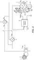
Figure 2 is a schematic of a modified manual trim according to the disclosure. -
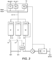
Figure 3 is a schematic of a preferred arrangement according to the disclosure. - A conventional manual trim will now be briefly described with reference to
Fig. 1 . The description relates to the control of a horizontal stabiliser, but the same principles also apply to other moveable surfaces, flaps etc. driven by an actuator. - A trim wheel 1 is provided in the cockpit e.g. in the cockpit central panel to be easily accessible to the pilot. For manual control of the HSTA, the pilot turns the trim wheel by an amount corresponding to the amount that the tail stabiliser 3 or other moveable surface is to be adjusted. Rotation of the trim wheel 1 is translated by a linkage 4 comprising links, cables and pulleys, to the actuator 2, and corresponding movement of the actuator drives the
moveable surface 3 as commanded. The pilot is informed by the rotary position of the trim wheel 1 of the position of themoveable surface 3. The rotary position of the trim wheel 1 also informs the pilot of the position of themoveable surface 3 when it has been driven automatically, as the trim wheel 1 is back driven by the linkage 4 responsive to movement of the HSTA. - As mentioned above, the linkage in such systems is complex and bulky and position feedback is not highly accurate due to the long transfer chain.
- In the system of the present disclosure, described with reference to
Fig. 2 , amotor 5 and a resolver 6 are installed at the trim wheel 1'. In addition, the mechanical input to the HSTA is replaced by amotor 7 and aresolver 8. Thus, the complex, bulky linkage 4 is replaced. This will simplify maintenance. - When a pilot wishes to take manual control of the HSTA, he turns the trim wheel 1. The rotation is detected by the first resolver 6, via the
first motor 5, and is converted to an angle command θTRIM. The angle command is received by thesecond motor 7 connected to the HSTA 20 to drive the HSTA 20 to cause a corresponding movement of themoveable surface 30. - In the preferred arrangement, the
second resolver 8, at the HSTA, provides position feedback as part of the control. Theresolver 8 detects the angular position of the moveable surface 30 (or the drive position of the HSTA 2). This provides an output indicative of mechanical input angle θMI. When an angle command is sent from the trim wheel resolver 6, this is compared e.g. at comparator orsummer 9 with the mechanical input angle from the HSTAresolver 8 and a command is sent to the HSTA based on the difference in the commanded position and the actual position. This command is sent to themotor 7 of the HSTA. - Feedback of the mechanical input angle, indicative of the position of the moveable surface, can also be fed back, from the HSTA
resolver 8 mechanical input angle θMI, to thetrim wheel motor 5, viacomparator 11, to turn the trim wheel 1' (via first motor 5) so that its rotary position corresponds to the position of the moveable surface so that, even when the HSTA is controlled automatically, via the FCC (not shown) the pilot has a visual indication - the trim wheel 1' position - as to the current position of the moveable surface. - In a preferred embodiment, the system is also arranged such that if a pilot provides a manual command to the HSTA, as described above, this overrides the automatic FCC control by means of an
override circuit 10. - A conventional HSTA architecture includes three electrical motors connected to the FCC for the automatic control, as well as a manual input (as shown in
Fig. 1 ) for the pilot. When the pilot takes control by means of the trim wheel 1' an override mechanism de-clutches the electrical motors to give priority to the manual pilot operation.
With reference toFig. 3 , during automatic control, control commands ISM are provided from the FCC (not shown) to control threeelectric motors 12,12' which drive the actuator (not shown) by signals ELAC1, ELAC2 viamechanical stops 14. In one preferred embodiment of the system of this disclosure described above in relation toFig. 2 , one of the three electric motors 12' usually used for the automatic FCC control can also be used as theHSTA motor 7 for the manual control. This also avoids the need for a mechanical overriding system, as the overriding function can be performed electrically. - As shown in, and described above in relation to,
Fig. 2 , once the trim wheel 1' is operated for the pilot to take manual control, this is compared with the FCC command, at 10. If the trim wheel command supersedes the FCC control, theelectrical motors 12 are overridden - i.e. disconnected. In the preferred embodiment, when the manual operation takes over, two of the threemotors 12 are disconnected e.g. by switches 11. The third motor 12', however, is used as aninput motor 7 in the manual control architecture ofFig. 2 . - As the motors and resolvers communicate via electric signals, the mechanical input and linkage is removed.
- Using this preferred architecture, there is no need for a separate mechanical manual input to the HSTA, thus greatly simplifying the system and providing a simpler, smaller, lighter system that is easier to maintain and that is more responsive, thus improving position feedback accuracy.
Claims (12)
- An assembly for manual control of an actuator for controlling the position of a moveable surface, the assembly comprising a user-operated manual control element (1'), and transfer means configured to translate movement of the manual control element to movement of an actuator associated therewith, in use; the transfer means comprising a first motor (5) and a first resolver (6) connected to the manual control element and a second motor (7) and a second resolver (8) arranged to communicate with the first motor and the first resolver and to cause corresponding movement of the actuator, in use.
- The assembly of claim 1, wherein the manual control element is configured such that the user moves it by an amount or degree corresponding to or proportional to the desired movement of the actuator and of the movable surface.
- The assembly of claim 2, wherein the manual control element is a rotatable element.
- The assembly of claim 3, wherein the rotatable element is a wheel or, more specifically, a trim wheel.
- The assembly of any preceding claim, whereby the first resolver communicates an electrical command signal, indicative of movement of the manual control element, to the second motor to cause the corresponding movement of the actuator.
- The assembly of claim 5, wherein the electrical command signal is compared to a feedback signal from the second resolver, indicative of a position of the actuator, and a difference signal is communicated to the second motor to cause the corresponding movement of the actuator.
- The assembly of any preceding claim, further comprising means for providing a feedback signal from the second resolver to the first motor indicative of the position of the actuator.
- The assembly of claim 7, whereby the feedback signal causes corresponding movement of the manual control element.
- The assembly of any preceding claim, configured to control movement of a horizontal stabiliser trim actuator, HSTA, of an aircraft.
- An assembly for controlling movement of a movable surface comprising an actuator (20) in engagement with the surface and an assembly as claimed in any preceding claim for controlling the actuator.
- The assembly of claim 10, further comprising an automatic control arrangement for automatic control of the actuator via a control computer, and wherein operation of the assembly for manual control overrides operation of the automatic control arrangement.
- The assembly of claim 11, wherein the arrangement for automatic control of the actuator comprises a plurality of motors providing communication between the control computer and the actuator, and wherein, when the manual control overrides the automatic control, one of said plurality of motors operates as said second motor and the other(s) of the plurality of motors is/are disconnected.
Priority Applications (4)
| Application Number | Priority Date | Filing Date | Title |
|---|---|---|---|
| EP17306961.8A EP3505440B1 (en) | 2017-12-28 | 2017-12-28 | Horizontal stabilizer trim actuator assembly |
| BR102018071409-0A BR102018071409B1 (en) | 2017-12-28 | 2018-10-17 | ASSEMBLY FOR CONTROLLING MOVEMENT OF A MOVING SURFACE |
| CA3021492A CA3021492A1 (en) | 2017-12-28 | 2018-10-18 | Horizontal stabilizer trim actuator assembly |
| US16/167,715 US11554852B2 (en) | 2017-12-28 | 2018-10-23 | Horizontal stabilizer trim actuator assembly |
Applications Claiming Priority (1)
| Application Number | Priority Date | Filing Date | Title |
|---|---|---|---|
| EP17306961.8A EP3505440B1 (en) | 2017-12-28 | 2017-12-28 | Horizontal stabilizer trim actuator assembly |
Publications (2)
| Publication Number | Publication Date |
|---|---|
| EP3505440A1 true EP3505440A1 (en) | 2019-07-03 |
| EP3505440B1 EP3505440B1 (en) | 2022-03-09 |
Family
ID=60971970
Family Applications (1)
| Application Number | Title | Priority Date | Filing Date |
|---|---|---|---|
| EP17306961.8A Active EP3505440B1 (en) | 2017-12-28 | 2017-12-28 | Horizontal stabilizer trim actuator assembly |
Country Status (3)
| Country | Link |
|---|---|
| US (1) | US11554852B2 (en) |
| EP (1) | EP3505440B1 (en) |
| CA (1) | CA3021492A1 (en) |
Families Citing this family (2)
| Publication number | Priority date | Publication date | Assignee | Title |
|---|---|---|---|---|
| EP3650336A1 (en) * | 2018-11-12 | 2020-05-13 | Goodrich Actuation Systems SAS | Trim control system |
| EP3816042B1 (en) * | 2019-10-28 | 2022-01-12 | AIRBUS HELICOPTERS DEUTSCHLAND GmbH | A vehicle control system for autonomous, remotely-controlled, or manual operation of a vehicle |
Citations (6)
| Publication number | Priority date | Publication date | Assignee | Title |
|---|---|---|---|---|
| US4840031A (en) | 1987-05-05 | 1989-06-20 | Fluid Regulators Corp. | Control system for fluid pressure operated actuator |
| US6439512B1 (en) | 2000-08-24 | 2002-08-27 | Hr Textron, Inc. | All-hydraulic powered horizontal stabilizer trim control surface position control system |
| EP2415669A1 (en) * | 2010-08-04 | 2012-02-08 | EUROCOPTER DEUTSCHLAND GmbH | Control system |
| US8376283B2 (en) * | 2008-11-19 | 2013-02-19 | Eurocopter Deutschland, GmbH | Device for switchable pilot control forces |
| US8935015B2 (en) | 2011-05-09 | 2015-01-13 | Parker-Hannifin Corporation | Flight control system with alternate control path |
| US20150108281A1 (en) * | 2013-10-22 | 2015-04-23 | Ratier Figeac | Method for monitoring the operation of an aircraft piloting device and an aircraft piloting device thus monitored |
Family Cites Families (18)
| Publication number | Priority date | Publication date | Assignee | Title |
|---|---|---|---|---|
| US2696956A (en) * | 1951-01-09 | 1954-12-14 | Douglas Aircraft Co Inc | Safety mechanism for operating control surfaces |
| US3038352A (en) * | 1960-04-07 | 1962-06-12 | Bendix Corp | Dual speed trim actuator mechanism and control system for a control surface of an aircraft |
| US4825375A (en) * | 1985-12-23 | 1989-04-25 | Boeing Company | Apparatus and methods for apportioning commands between aircraft flight control surfaces |
| US5286203A (en) * | 1992-10-07 | 1994-02-15 | Aai Microflite Simulation International | Simulating horizontal stabilizer trimming in an aircraft |
| GB0127254D0 (en) * | 2001-11-13 | 2002-01-02 | Lucas Industries Ltd | Aircraft flight surface control system |
| US7556224B2 (en) | 2005-12-27 | 2009-07-07 | Honeywell International Inc. | Distributed flight control surface actuation system |
| US8380364B2 (en) * | 2006-05-17 | 2013-02-19 | Textron Innovations, Inc. | Manual and computerized flight control system with natural feedback |
| US9340278B2 (en) | 2006-05-17 | 2016-05-17 | Textron Innovations, Inc. | Flight control system |
| US7658349B2 (en) | 2006-10-26 | 2010-02-09 | Honeywell International Inc. | Pilot flight control stick haptic feedback system and method |
| US20080156939A1 (en) * | 2007-01-03 | 2008-07-03 | Honeywell International, Inc. | Active pilot flight control stick system with passive electromagnetic feedback |
| US8960031B2 (en) | 2009-09-01 | 2015-02-24 | Parker-Hannifin Corporation | Aircraft stabilizer actuator |
| US20110251739A1 (en) | 2010-04-09 | 2011-10-13 | Honeywell International Inc. | Distributed fly-by-wire system |
| US10065728B2 (en) * | 2011-06-30 | 2018-09-04 | Parker-Hannifin Corporation | Horizontal stabilizer trim actuator failure detection system and method using position sensors |
| DE102011115362A1 (en) * | 2011-10-07 | 2013-04-11 | Liebherr-Aerospace Lindenberg Gmbh | Modular electronic flight control system for controlling actuators in e.g. primary flight controls of e.g. civilian aircraft, has control units comprising electronic control of actuators and arranged and distributed in airplane |
| US8812177B2 (en) | 2012-02-10 | 2014-08-19 | Bell Helicopter Textron Inc. | Integrated aircraft flight control units |
| FR3008457B1 (en) | 2013-07-15 | 2015-07-24 | Eurocopter France | COUPLING MECHANISM BETWEEN A MANUAL FLIGHT CONTROL ARRANGEMENT AND A "TRIM" CYLINDER EQUIPPED WITH AN AIRCRAFT |
| FR3021627B1 (en) | 2014-05-28 | 2016-06-10 | Airbus Helicopters | ALARM DEVICE FOR A TILT SIGNAL GYROVAN PILOT USING A "TRIM CYLINDER" CONNECTED TO A FLIGHT CONTROL MEMBER |
| US9446838B2 (en) * | 2014-08-14 | 2016-09-20 | Gulfstream Aerospace Corporation | Systems for inceptor control in fly-by-wire aircraft systems |
-
2017
- 2017-12-28 EP EP17306961.8A patent/EP3505440B1/en active Active
-
2018
- 2018-10-18 CA CA3021492A patent/CA3021492A1/en active Pending
- 2018-10-23 US US16/167,715 patent/US11554852B2/en active Active
Patent Citations (6)
| Publication number | Priority date | Publication date | Assignee | Title |
|---|---|---|---|---|
| US4840031A (en) | 1987-05-05 | 1989-06-20 | Fluid Regulators Corp. | Control system for fluid pressure operated actuator |
| US6439512B1 (en) | 2000-08-24 | 2002-08-27 | Hr Textron, Inc. | All-hydraulic powered horizontal stabilizer trim control surface position control system |
| US8376283B2 (en) * | 2008-11-19 | 2013-02-19 | Eurocopter Deutschland, GmbH | Device for switchable pilot control forces |
| EP2415669A1 (en) * | 2010-08-04 | 2012-02-08 | EUROCOPTER DEUTSCHLAND GmbH | Control system |
| US8935015B2 (en) | 2011-05-09 | 2015-01-13 | Parker-Hannifin Corporation | Flight control system with alternate control path |
| US20150108281A1 (en) * | 2013-10-22 | 2015-04-23 | Ratier Figeac | Method for monitoring the operation of an aircraft piloting device and an aircraft piloting device thus monitored |
Also Published As
| Publication number | Publication date |
|---|---|
| US11554852B2 (en) | 2023-01-17 |
| CA3021492A1 (en) | 2019-06-28 |
| EP3505440B1 (en) | 2022-03-09 |
| BR102018071409A2 (en) | 2019-07-16 |
| US20190202545A1 (en) | 2019-07-04 |
Similar Documents
| Publication | Publication Date | Title |
|---|---|---|
| US8080966B2 (en) | Motor control architecture for simultaneously controlling multiple motors | |
| US7658349B2 (en) | Pilot flight control stick haptic feedback system and method | |
| US7556224B2 (en) | Distributed flight control surface actuation system | |
| EP3495261B1 (en) | Combined active stick and control boost actuator system | |
| EP3403924B1 (en) | In-cockpit control of a fixed wing aircraft | |
| EP2465770B1 (en) | Adjustment of wings for variable camber for optimum take-off and landing configuration | |
| EP1908685B1 (en) | Motor balanced active user interface assembly | |
| EP3208189B1 (en) | Aerodynamic control surface movement monitoring system | |
| EP4025495B1 (en) | Rudder and brake pedal assembly | |
| US11396363B2 (en) | Open and closed control of actuators, which drive aerodynamic control surfaces of an aircraft | |
| US11554852B2 (en) | Horizontal stabilizer trim actuator assembly | |
| EP4029776B1 (en) | Actuator control for force fight mitigation | |
| US10562609B2 (en) | High trim demand relief | |
| US20070108342A1 (en) | Reconfigurable flight control surface actuation system and method | |
| US11975861B2 (en) | Retrofit aircraft autothrottle control for aircraft with engine controllers | |
| US11027825B2 (en) | Split-aileron control | |
| EP2987722B1 (en) | Rotorcraft autopilot control | |
| US20240409203A1 (en) | Hybrid Flight Control System | |
| US12534187B2 (en) | Mode-dependent tactile feedback profiles for an inceptor | |
| BR102018071409B1 (en) | ASSEMBLY FOR CONTROLLING MOVEMENT OF A MOVING SURFACE | |
| KR101885663B1 (en) | Fly-by-wire flight control system with backup mechanical flight control system |
Legal Events
| Date | Code | Title | Description |
|---|---|---|---|
| PUAI | Public reference made under article 153(3) epc to a published international application that has entered the european phase |
Free format text: ORIGINAL CODE: 0009012 |
|
| STAA | Information on the status of an ep patent application or granted ep patent |
Free format text: STATUS: THE APPLICATION HAS BEEN PUBLISHED |
|
| AK | Designated contracting states |
Kind code of ref document: A1 Designated state(s): AL AT BE BG CH CY CZ DE DK EE ES FI FR GB GR HR HU IE IS IT LI LT LU LV MC MK MT NL NO PL PT RO RS SE SI SK SM TR |
|
| AX | Request for extension of the european patent |
Extension state: BA ME |
|
| STAA | Information on the status of an ep patent application or granted ep patent |
Free format text: STATUS: REQUEST FOR EXAMINATION WAS MADE |
|
| 17P | Request for examination filed |
Effective date: 20191231 |
|
| RBV | Designated contracting states (corrected) |
Designated state(s): AL AT BE BG CH CY CZ DE DK EE ES FI FR GB GR HR HU IE IS IT LI LT LU LV MC MK MT NL NO PL PT RO RS SE SI SK SM TR |
|
| STAA | Information on the status of an ep patent application or granted ep patent |
Free format text: STATUS: EXAMINATION IS IN PROGRESS |
|
| 17Q | First examination report despatched |
Effective date: 20200901 |
|
| GRAP | Despatch of communication of intention to grant a patent |
Free format text: ORIGINAL CODE: EPIDOSNIGR1 |
|
| STAA | Information on the status of an ep patent application or granted ep patent |
Free format text: STATUS: GRANT OF PATENT IS INTENDED |
|
| INTG | Intention to grant announced |
Effective date: 20211006 |
|
| GRAS | Grant fee paid |
Free format text: ORIGINAL CODE: EPIDOSNIGR3 |
|
| GRAA | (expected) grant |
Free format text: ORIGINAL CODE: 0009210 |
|
| STAA | Information on the status of an ep patent application or granted ep patent |
Free format text: STATUS: THE PATENT HAS BEEN GRANTED |
|
| AK | Designated contracting states |
Kind code of ref document: B1 Designated state(s): AL AT BE BG CH CY CZ DE DK EE ES FI FR GB GR HR HU IE IS IT LI LT LU LV MC MK MT NL NO PL PT RO RS SE SI SK SM TR |
|
| REG | Reference to a national code |
Ref country code: CH Ref legal event code: EP Ref country code: AT Ref legal event code: REF Ref document number: 1473950 Country of ref document: AT Kind code of ref document: T Effective date: 20220315 |
|
| REG | Reference to a national code |
Ref country code: IE Ref legal event code: FG4D |
|
| REG | Reference to a national code |
Ref country code: DE Ref legal event code: R096 Ref document number: 602017054306 Country of ref document: DE |
|
| REG | Reference to a national code |
Ref country code: LT Ref legal event code: MG9D |
|
| REG | Reference to a national code |
Ref country code: NL Ref legal event code: MP Effective date: 20220309 |
|
| PG25 | Lapsed in a contracting state [announced via postgrant information from national office to epo] |
Ref country code: SE Free format text: LAPSE BECAUSE OF FAILURE TO SUBMIT A TRANSLATION OF THE DESCRIPTION OR TO PAY THE FEE WITHIN THE PRESCRIBED TIME-LIMIT Effective date: 20220309 Ref country code: RS Free format text: LAPSE BECAUSE OF FAILURE TO SUBMIT A TRANSLATION OF THE DESCRIPTION OR TO PAY THE FEE WITHIN THE PRESCRIBED TIME-LIMIT Effective date: 20220309 Ref country code: NO Free format text: LAPSE BECAUSE OF FAILURE TO SUBMIT A TRANSLATION OF THE DESCRIPTION OR TO PAY THE FEE WITHIN THE PRESCRIBED TIME-LIMIT Effective date: 20220609 Ref country code: LT Free format text: LAPSE BECAUSE OF FAILURE TO SUBMIT A TRANSLATION OF THE DESCRIPTION OR TO PAY THE FEE WITHIN THE PRESCRIBED TIME-LIMIT Effective date: 20220309 Ref country code: HR Free format text: LAPSE BECAUSE OF FAILURE TO SUBMIT A TRANSLATION OF THE DESCRIPTION OR TO PAY THE FEE WITHIN THE PRESCRIBED TIME-LIMIT Effective date: 20220309 Ref country code: BG Free format text: LAPSE BECAUSE OF FAILURE TO SUBMIT A TRANSLATION OF THE DESCRIPTION OR TO PAY THE FEE WITHIN THE PRESCRIBED TIME-LIMIT Effective date: 20220609 |
|
| RAP4 | Party data changed (patent owner data changed or rights of a patent transferred) |
Owner name: GOODRICH ACTUATION SYSTEMS SAS |
|
| REG | Reference to a national code |
Ref country code: AT Ref legal event code: MK05 Ref document number: 1473950 Country of ref document: AT Kind code of ref document: T Effective date: 20220309 |
|
| PG25 | Lapsed in a contracting state [announced via postgrant information from national office to epo] |
Ref country code: LV Free format text: LAPSE BECAUSE OF FAILURE TO SUBMIT A TRANSLATION OF THE DESCRIPTION OR TO PAY THE FEE WITHIN THE PRESCRIBED TIME-LIMIT Effective date: 20220309 Ref country code: GR Free format text: LAPSE BECAUSE OF FAILURE TO SUBMIT A TRANSLATION OF THE DESCRIPTION OR TO PAY THE FEE WITHIN THE PRESCRIBED TIME-LIMIT Effective date: 20220610 Ref country code: FI Free format text: LAPSE BECAUSE OF FAILURE TO SUBMIT A TRANSLATION OF THE DESCRIPTION OR TO PAY THE FEE WITHIN THE PRESCRIBED TIME-LIMIT Effective date: 20220309 |
|
| RAP4 | Party data changed (patent owner data changed or rights of a patent transferred) |
Owner name: GOODRICH ACTUATION SYSTEMS SAS |
|
| PG25 | Lapsed in a contracting state [announced via postgrant information from national office to epo] |
Ref country code: NL Free format text: LAPSE BECAUSE OF FAILURE TO SUBMIT A TRANSLATION OF THE DESCRIPTION OR TO PAY THE FEE WITHIN THE PRESCRIBED TIME-LIMIT Effective date: 20220309 |
|
| PG25 | Lapsed in a contracting state [announced via postgrant information from national office to epo] |
Ref country code: SM Free format text: LAPSE BECAUSE OF FAILURE TO SUBMIT A TRANSLATION OF THE DESCRIPTION OR TO PAY THE FEE WITHIN THE PRESCRIBED TIME-LIMIT Effective date: 20220309 Ref country code: SK Free format text: LAPSE BECAUSE OF FAILURE TO SUBMIT A TRANSLATION OF THE DESCRIPTION OR TO PAY THE FEE WITHIN THE PRESCRIBED TIME-LIMIT Effective date: 20220309 Ref country code: RO Free format text: LAPSE BECAUSE OF FAILURE TO SUBMIT A TRANSLATION OF THE DESCRIPTION OR TO PAY THE FEE WITHIN THE PRESCRIBED TIME-LIMIT Effective date: 20220309 Ref country code: PT Free format text: LAPSE BECAUSE OF FAILURE TO SUBMIT A TRANSLATION OF THE DESCRIPTION OR TO PAY THE FEE WITHIN THE PRESCRIBED TIME-LIMIT Effective date: 20220711 Ref country code: ES Free format text: LAPSE BECAUSE OF FAILURE TO SUBMIT A TRANSLATION OF THE DESCRIPTION OR TO PAY THE FEE WITHIN THE PRESCRIBED TIME-LIMIT Effective date: 20220309 Ref country code: EE Free format text: LAPSE BECAUSE OF FAILURE TO SUBMIT A TRANSLATION OF THE DESCRIPTION OR TO PAY THE FEE WITHIN THE PRESCRIBED TIME-LIMIT Effective date: 20220309 Ref country code: CZ Free format text: LAPSE BECAUSE OF FAILURE TO SUBMIT A TRANSLATION OF THE DESCRIPTION OR TO PAY THE FEE WITHIN THE PRESCRIBED TIME-LIMIT Effective date: 20220309 Ref country code: AT Free format text: LAPSE BECAUSE OF FAILURE TO SUBMIT A TRANSLATION OF THE DESCRIPTION OR TO PAY THE FEE WITHIN THE PRESCRIBED TIME-LIMIT Effective date: 20220309 |
|
| PG25 | Lapsed in a contracting state [announced via postgrant information from national office to epo] |
Ref country code: PL Free format text: LAPSE BECAUSE OF FAILURE TO SUBMIT A TRANSLATION OF THE DESCRIPTION OR TO PAY THE FEE WITHIN THE PRESCRIBED TIME-LIMIT Effective date: 20220309 Ref country code: IS Free format text: LAPSE BECAUSE OF FAILURE TO SUBMIT A TRANSLATION OF THE DESCRIPTION OR TO PAY THE FEE WITHIN THE PRESCRIBED TIME-LIMIT Effective date: 20220709 Ref country code: AL Free format text: LAPSE BECAUSE OF FAILURE TO SUBMIT A TRANSLATION OF THE DESCRIPTION OR TO PAY THE FEE WITHIN THE PRESCRIBED TIME-LIMIT Effective date: 20220309 |
|
| REG | Reference to a national code |
Ref country code: DE Ref legal event code: R097 Ref document number: 602017054306 Country of ref document: DE |
|
| PLBE | No opposition filed within time limit |
Free format text: ORIGINAL CODE: 0009261 |
|
| STAA | Information on the status of an ep patent application or granted ep patent |
Free format text: STATUS: NO OPPOSITION FILED WITHIN TIME LIMIT |
|
| PG25 | Lapsed in a contracting state [announced via postgrant information from national office to epo] |
Ref country code: DK Free format text: LAPSE BECAUSE OF FAILURE TO SUBMIT A TRANSLATION OF THE DESCRIPTION OR TO PAY THE FEE WITHIN THE PRESCRIBED TIME-LIMIT Effective date: 20220309 |
|
| 26N | No opposition filed |
Effective date: 20221212 |
|
| PG25 | Lapsed in a contracting state [announced via postgrant information from national office to epo] |
Ref country code: SI Free format text: LAPSE BECAUSE OF FAILURE TO SUBMIT A TRANSLATION OF THE DESCRIPTION OR TO PAY THE FEE WITHIN THE PRESCRIBED TIME-LIMIT Effective date: 20220309 |
|
| REG | Reference to a national code |
Ref country code: CH Ref legal event code: PL |
|
| REG | Reference to a national code |
Ref country code: BE Ref legal event code: MM Effective date: 20221231 |
|
| PG25 | Lapsed in a contracting state [announced via postgrant information from national office to epo] |
Ref country code: LU Free format text: LAPSE BECAUSE OF NON-PAYMENT OF DUE FEES Effective date: 20221228 |
|
| PG25 | Lapsed in a contracting state [announced via postgrant information from national office to epo] |
Ref country code: LI Free format text: LAPSE BECAUSE OF NON-PAYMENT OF DUE FEES Effective date: 20221231 Ref country code: IE Free format text: LAPSE BECAUSE OF NON-PAYMENT OF DUE FEES Effective date: 20221228 Ref country code: CH Free format text: LAPSE BECAUSE OF NON-PAYMENT OF DUE FEES Effective date: 20221231 |
|
| PG25 | Lapsed in a contracting state [announced via postgrant information from national office to epo] |
Ref country code: BE Free format text: LAPSE BECAUSE OF NON-PAYMENT OF DUE FEES Effective date: 20221231 |
|
| PG25 | Lapsed in a contracting state [announced via postgrant information from national office to epo] |
Ref country code: HU Free format text: LAPSE BECAUSE OF FAILURE TO SUBMIT A TRANSLATION OF THE DESCRIPTION OR TO PAY THE FEE WITHIN THE PRESCRIBED TIME-LIMIT; INVALID AB INITIO Effective date: 20171228 |
|
| PG25 | Lapsed in a contracting state [announced via postgrant information from national office to epo] |
Ref country code: CY Free format text: LAPSE BECAUSE OF FAILURE TO SUBMIT A TRANSLATION OF THE DESCRIPTION OR TO PAY THE FEE WITHIN THE PRESCRIBED TIME-LIMIT Effective date: 20220309 |
|
| PG25 | Lapsed in a contracting state [announced via postgrant information from national office to epo] |
Ref country code: MK Free format text: LAPSE BECAUSE OF FAILURE TO SUBMIT A TRANSLATION OF THE DESCRIPTION OR TO PAY THE FEE WITHIN THE PRESCRIBED TIME-LIMIT Effective date: 20220309 |
|
| PG25 | Lapsed in a contracting state [announced via postgrant information from national office to epo] |
Ref country code: MC Free format text: LAPSE BECAUSE OF FAILURE TO SUBMIT A TRANSLATION OF THE DESCRIPTION OR TO PAY THE FEE WITHIN THE PRESCRIBED TIME-LIMIT Effective date: 20220309 |
|
| PG25 | Lapsed in a contracting state [announced via postgrant information from national office to epo] |
Ref country code: TR Free format text: LAPSE BECAUSE OF FAILURE TO SUBMIT A TRANSLATION OF THE DESCRIPTION OR TO PAY THE FEE WITHIN THE PRESCRIBED TIME-LIMIT Effective date: 20220309 Ref country code: MC Free format text: LAPSE BECAUSE OF FAILURE TO SUBMIT A TRANSLATION OF THE DESCRIPTION OR TO PAY THE FEE WITHIN THE PRESCRIBED TIME-LIMIT Effective date: 20220309 |
|
| PG25 | Lapsed in a contracting state [announced via postgrant information from national office to epo] |
Ref country code: MT Free format text: LAPSE BECAUSE OF FAILURE TO SUBMIT A TRANSLATION OF THE DESCRIPTION OR TO PAY THE FEE WITHIN THE PRESCRIBED TIME-LIMIT Effective date: 20220309 |
|
| PGFP | Annual fee paid to national office [announced via postgrant information from national office to epo] |
Ref country code: GB Payment date: 20251229 Year of fee payment: 9 |
|
| PGFP | Annual fee paid to national office [announced via postgrant information from national office to epo] |
Ref country code: IT Payment date: 20251210 Year of fee payment: 9 |
|
| PGFP | Annual fee paid to national office [announced via postgrant information from national office to epo] |
Ref country code: FR Payment date: 20251230 Year of fee payment: 9 |
|
| PGFP | Annual fee paid to national office [announced via postgrant information from national office to epo] |
Ref country code: DE Payment date: 20251231 Year of fee payment: 9 |