EP3505392B1 - Method and system of installation of a plurality of droppers of an overhead contact system section - Google Patents
Method and system of installation of a plurality of droppers of an overhead contact system section Download PDFInfo
- Publication number
- EP3505392B1 EP3505392B1 EP18305001.2A EP18305001A EP3505392B1 EP 3505392 B1 EP3505392 B1 EP 3505392B1 EP 18305001 A EP18305001 A EP 18305001A EP 3505392 B1 EP3505392 B1 EP 3505392B1
- Authority
- EP
- European Patent Office
- Prior art keywords
- platform
- contact
- wire
- droppers
- dropper
- Prior art date
- Legal status (The legal status is an assumption and is not a legal conclusion. Google has not performed a legal analysis and makes no representation as to the accuracy of the status listed.)
- Active
Links
Images

Classifications
-
- B—PERFORMING OPERATIONS; TRANSPORTING
- B60—VEHICLES IN GENERAL
- B60M—POWER SUPPLY LINES, AND DEVICES ALONG RAILS, FOR ELECTRICALLY- PROPELLED VEHICLES
- B60M1/00—Power supply lines for contact with collector on vehicle
- B60M1/12—Trolley lines; Accessories therefor
- B60M1/28—Manufacturing or repairing trolley lines
-
- B—PERFORMING OPERATIONS; TRANSPORTING
- B60—VEHICLES IN GENERAL
- B60M—POWER SUPPLY LINES, AND DEVICES ALONG RAILS, FOR ELECTRICALLY- PROPELLED VEHICLES
- B60M1/00—Power supply lines for contact with collector on vehicle
- B60M1/12—Trolley lines; Accessories therefor
- B60M1/20—Arrangements for supporting or suspending trolley wires, e.g. from buildings
- B60M1/22—Separate lines from which power lines are suspended, e.g. catenary lines, supporting-lines under tension
-
- B—PERFORMING OPERATIONS; TRANSPORTING
- B60—VEHICLES IN GENERAL
- B60M—POWER SUPPLY LINES, AND DEVICES ALONG RAILS, FOR ELECTRICALLY- PROPELLED VEHICLES
- B60M1/00—Power supply lines for contact with collector on vehicle
- B60M1/12—Trolley lines; Accessories therefor
- B60M1/20—Arrangements for supporting or suspending trolley wires, e.g. from buildings
- B60M1/23—Arrangements for suspending trolley wires from catenary line
-
- G—PHYSICS
- G01—MEASURING; TESTING
- G01S—RADIO DIRECTION-FINDING; RADIO NAVIGATION; DETERMINING DISTANCE OR VELOCITY BY USE OF RADIO WAVES; LOCATING OR PRESENCE-DETECTING BY USE OF THE REFLECTION OR RERADIATION OF RADIO WAVES; ANALOGOUS ARRANGEMENTS USING OTHER WAVES
- G01S17/00—Systems using the reflection or reradiation of electromagnetic waves other than radio waves, e.g. lidar systems
- G01S17/02—Systems using the reflection of electromagnetic waves other than radio waves
- G01S17/06—Systems determining position data of a target
- G01S17/08—Systems determining position data of a target for measuring distance only
Definitions
- the present invention concerns a method and a system of installation of the droppers of an overhead contact system.
- Figure 1 represents a first type of an overhead contact system section, sometimes also called a catenary system.
- a section 10 of the overhead contact system comprises one contact wire 12 suspended above the pair of rails 2 and 3 of a track 1.
- the contact wire 12 is hung by means of a plurality of droppers 21 - 28 to one messenger wire 14.
- the messenger wire 14 is supported at intervals by support poles erected successively along the track 1. Two successive support poles delimit a section of the overhead contact system, such as the support poles 31 and 32 delimiting the section 10.
- the messenger wire assumes the form of a curve that is called a catenary. This curve results from the balance between the different mechanical forces applied on the messenger wire. It can be precisely calculated given the distance between the support poles, the mass per unit length of the contact line, the messenger line and the droppers, and the number of droppers and the interval between two successive droppers.
- the contact wire must be set at a predetermined height relative to the rails to be sure that the pantograph of a train running on the track stays in a suitable contact with it: This height must not be too high to avoid the pantograph to lose the contact with the contact wire, the formation of a gap leading to an electric arcs and a variation in the electric power supplied by the overhead contact line to the train; This height must not be too low to avoid the pantograph to lift the contact wire and apply a mechanical force while the train is moving which would cause the breaking of the contact wire.
- a workman walks from one pole to the other along the track and paints marks on the ballast above which a dropper has to be installed.
- Prefabricated droppers are sourced and delivered on site in yarns of different but defined lengths.
- the yards of prefabricated droppers are loaded on a lifting platform.
- the platform operated manually, is then moved along the track and stopped roughly in correspondence with each mark on the ballast.
- the workman reads the layout to determine the length of the dropper to be installed at this point.
- a dropper is taken from the suitable yarn and is clamped by its ends to the messenger wire and the contact wire respectively.
- Document JP 2004 217149 A discloses a platform for the installation of droppers between a messenger wire and a contact wire.
- the platform comprises a trolley movable vertically (Z direction) and longitudinally (Y direction).
- the trolley is stopped when the actual position measured along the contact wire by a sensor corresponds to a predefined position for the installation of a dropper.
- the dropper to be installed is retrieved by the worker from a container located on the platform, is hung by the worker on the messenger wire, and the free end of the hunger is inserted by the worker into a tool of the platform for anchoring the contact wire to the hunger.
- the object of the present invention is to remedy this problem.
- the subject-matter of the invention is a method according to claim 7 and a system according to claim 1 to implement said method.
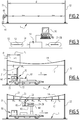
- Figure 2 corresponds to a first step consisting in the measurement of the distance d between the two successive supporting poles 31 and 32 of the considered section of the overhead contact system.
- a laser scanner 40 is used by a workman 41 to realize this measurement.
- a GPS device is used in place of the laser scanner.
- Other parameters of interest may also be measured in this first step, such as the altitude difference between the support poles 31 and 32, when the track 1 is not horizontal.
- Figure 3 corresponds to a second step and a third step of the method.
- a computer 50 is used to determine a layout plan of section 10 to be realized.
- Information is inputted into a computer 50.
- Said information comprises at least the distance d measured in the first step, and advantageously the other parameters of interest measured in the first step.
- This information may comprise also configuration variables, such that the number of droppers per section.
- the computer 50 is programmed to determine the form of the messenger wire 14, taking into account the information input.
- the layout plan output by computer 50 indicates, for each dropper 21 to 28 of section 10, an id of the dropper, a length of the dropper and a position pi of the dropper.
- the position pi of the i th dropper may for example be the distance from the support pole 31 chosen as reference.
- each dropper is manufactured at its correct length as indicated by the layout plan.
- a dedicated machine 51 is used. It is interfaced with the computer 50, which thus command the manufacturing of the droppers.
- the machine 51 assembles the different components of a dropper. For example, a cable is cut at the correct length 52 and clamp mechanisms 53 and 54 are fixed at each of its ends to obtain the desired dropper. Droppers 21 to 28 are thus fabricated.
- Figure 4 represent a fourth step and a fifth step.
- a first platform 60 is driven along track 1, as indicated by arrow V, from the support pole 31 to the support pole 32.
- the first platform 60 is equipped with a positioning unit 61 for determining the actual position p of the first platform 60.
- the positioning unit 61 comprises preferably an odometer to provide a precise positioning of the first platform.
- the position p output by the position unit 61 is reset when the first platform 60 passes the support pole 31 which is taken as a reference.
- the position p given at each time by the position unit 61 is the distance from the support pole 31.
- the first platform 60 also comprises a marking device 70 capable of marking the contact wire 12.
- the marking device 70 comprises a paint container 71, an actuated valve 72 and a nozzle 73 situated at the extremity of a mast so as to be in the vicinity of the contact line 12. Each time the valve is actuated, a spray of paint is applied through the nozzle onto the contact line.
- the marking device 70 is actuated by the positioning unit 61 each time the current position p of the first platform 60 is equal to the position pi of a dropper as indicated by the layout plan, which have been loaded into the positioning unit 61.
- the contact wire 12 has a plurality of marks mi, mark m i corresponding to the point where the ⁇ th dropper has to be installed.
- mark m 1 has been painted on contact wire 12 at position p 1 and mark m 2 is in the process of being applied at position p 2 .
- the first platform 60 is also equipped with a dedicated system that is able to apply the final tension to the contact wire 12.
- the tension is applied on the contact wire 12 during the movement of the first platform 60.
- the marks are then drawn on the contact wire correctly stretched. A better precision on the location of the marks is thus obtained.
- Figure 5 represent a sixth step and a seventh step.
- a second platform 80 is moved along the track 1, as indicated by arrow V, from the support pole 31 to the support pole 32.
- the second platform is provided with an aerial device 82.
- the aerial device 82 is loaded with the droppers 21 to 28 which have been prepared and have to be installed.
- the droppers are preferably placed into a delivery means 81, such that they will be presented to the workman 83 in the order of their installation as the second platform 80 moves along section 10.
- the workman 83 when the workman 83 can see mark mi on the contact wire 12, he stops the second platform 80 and fixes the corresponding dropper between the messenger wire and a contact wire in registration with mark mi.
- droppers 21 and 22 have been installed, and dropper 23 is in the process of being installed.
- the workman drives the second platform 80 to the next mark. This process is repeated until the support pole 32 is reached.
- the computer is programmed to calculate a layout plan suitable for the type of overhead contact system to be realized.
- the type of overhead contact system to be realized may be a configuration parameter the operator has to initially set.
- the machine is also adapted to interpret one suitable layout plan and to manufacture the correct dropper for the type of overhead contact system to be realized.
- the first platform is adapted to put marks on each of the two contact wires.
- the measurement means used in the first step to measure the relevant data on site may be placed onboard the first platform and operated automatically.
- the measurement means are activated to get at least the distance with the second post. This and other measurements are remotely transmitted to the computer on the ground.
- the computer is also onboard the first platform to determine the correct layout plan and to pilot the unit to mark the contact wire or wires.
- the layout plan is remotely transmitted to the machine, located on the ground, to prepare the droppers.
- the machine is onboard the second platform to manufacture the droppers, preferably as the installation process goes on and the second platform moves along the tracks.
- a unique platform is used throughout the method, which combines the means arranged on the first and second platforms of the previous embodiments.
- the automatic marking is faster and more reliable.
- the determination of the layout plan on site allows taking into account the real and exact configuration of the overhead contact system and the track, as they have been realized.
- the method provides a precise installation of the droppers with the exact length so that the overhead contact system obtained is within the tolerances required for such a system. A lengthy and painful process of adjusting the droppers once in place to respect these tolerances can be spared.
- the system may comprise redundant components.
- the system comprises two marking devices, so that, in case of failure of the first position device, the second device is used and the process can still be realized.
Landscapes
- Engineering & Computer Science (AREA)
- Mechanical Engineering (AREA)
- Manufacturing & Machinery (AREA)
- Length Measuring Devices With Unspecified Measuring Means (AREA)
- Train Traffic Observation, Control, And Security (AREA)
- Electric Cable Installation (AREA)
Description
- The present invention concerns a method and a system of installation of the droppers of an overhead contact system.
-
Figure 1 represents a first type of an overhead contact system section, sometimes also called a catenary system. Asection 10 of the overhead contact system comprises onecontact wire 12 suspended above the pair ofrails 2 and 3 of atrack 1. Thecontact wire 12 is hung by means of a plurality of droppers 21 - 28 to onemessenger wire 14. Themessenger wire 14 is supported at intervals by support poles erected successively along thetrack 1. Two successive support poles delimit a section of the overhead contact system, such as thesupport poles section 10. - Between two successive support poles, the messenger wire assumes the form of a curve that is called a catenary. This curve results from the balance between the different mechanical forces applied on the messenger wire. It can be precisely calculated given the distance between the support poles, the mass per unit length of the contact line, the messenger line and the droppers, and the number of droppers and the interval between two successive droppers.
- On the contrary, the contact wire must be set at a predetermined height relative to the rails to be sure that the pantograph of a train running on the track stays in a suitable contact with it: This height must not be too high to avoid the pantograph to lose the contact with the contact wire, the formation of a gap leading to an electric arcs and a variation in the electric power supplied by the overhead contact line to the train; This height must not be too low to avoid the pantograph to lift the contact wire and apply a mechanical force while the train is moving which would cause the breaking of the contact wire.
- Knowing theoretically the position of the support poles, the height at which the contact wire must be set and the shape of the curve assumed by the messenger wire, the length and position of each dropper of a section can be calculated in the engineering and design department. A layout plan is thus generated and used on site as follows.
- A workman walks from one pole to the other along the track and paints marks on the ballast above which a dropper has to be installed.
- Prefabricated droppers are sourced and delivered on site in yarns of different but defined lengths.
- Once the contact and messenger wires have been suspended, the yards of prefabricated droppers are loaded on a lifting platform.
- The platform, operated manually, is then moved along the track and stopped roughly in correspondence with each mark on the ballast.
- At each stop, the workman reads the layout to determine the length of the dropper to be installed at this point.
- A dropper is taken from the suitable yarn and is clamped by its ends to the messenger wire and the contact wire respectively.
- Such an installation method involves heavy manual and time consuming operations to prepare and correctly position the droppers.
- It is prone to human errors cause by a misreading of the layout plan.
- In addition, when it is performed for repairing a fallen overhead contact system, a short period of time is allowed to minimize the impact on the operation of the railway. The workmen have to work as fast as possible in a time window of several hours. Often such a time window is only available at night, rendering the task particularly difficult, the workmen having to distinguish the marks on the ballast in low ambient light conditions.
- Document
JP 2004 217149 A - Other type of overhead contact system are known, in particular a second type comprising two contact wires supported by one single messenger wire or a third type comprising two contact wires supported by two messenger wires. Obviously, the droppers for each of these other types of overhead contact system are specific of that system, but are installed essentially in the same way than the droppers of the first type of overhead contact system. Thus these other types of overhead contact system suffer the same disadvantages.
- The object of the present invention is to remedy this problem.
- The subject-matter of the invention is a method according to claim 7 and a system according to
claim 1 to implement said method. - The invention will be more easily understood by way of a preferred embodiment illustrated by the accompanying drawings, on which:
-
Figure 1 is an overhead contact system obtained by the implementation of the method according to the invention; -
Figure 2 to 5 represent schematically the successive steps of the method according of the invention, each step involving a device, a machine or a platform constituting parts of the system according to the invention. - For realizing the
section 10 of the overhead contact system offigure 1 , the method of implantation of plurality of droppers according to the invention will now be described by reference tofigures 2 to 5 . -
Figure 2 corresponds to a first step consisting in the measurement of the distance d between the two successive supportingpoles - A
laser scanner 40 is used by aworkman 41 to realize this measurement. In another embodiment, a GPS device is used in place of the laser scanner. - Other parameters of interest may also be measured in this first step, such as the altitude difference between the
support poles track 1 is not horizontal. -
Figure 3 corresponds to a second step and a third step of the method. - In the second step, a
computer 50 is used to determine a layout plan ofsection 10 to be realized. - Information is inputted into a
computer 50. Said information comprises at least the distance d measured in the first step, and advantageously the other parameters of interest measured in the first step. This information may comprise also configuration variables, such that the number of droppers per section. - The
computer 50 is programmed to determine the form of themessenger wire 14, taking into account the information input. - The layout plan output by
computer 50 indicates, for eachdropper 21 to 28 ofsection 10, an id of the dropper, a length of the dropper and a position pi of the dropper. - The position pi of the ith dropper may for example be the distance from the
support pole 31 chosen as reference. - In the third step, each dropper is manufactured at its correct length as indicated by the layout plan. To this end, a
dedicated machine 51 is used. It is interfaced with thecomputer 50, which thus command the manufacturing of the droppers. - The
machine 51 assembles the different components of a dropper. For example, a cable is cut at thecorrect length 52 andclamp mechanisms -
Figure 4 represent a fourth step and a fifth step. - In the fourth step, a
first platform 60 is driven alongtrack 1, as indicated by arrow V, from thesupport pole 31 to thesupport pole 32. - The
first platform 60 is equipped with apositioning unit 61 for determining the actual position p of thefirst platform 60. Thepositioning unit 61 comprises preferably an odometer to provide a precise positioning of the first platform. The position p output by theposition unit 61 is reset when thefirst platform 60 passes thesupport pole 31 which is taken as a reference. Thus the position p given at each time by theposition unit 61 is the distance from thesupport pole 31. - The
first platform 60 also comprises amarking device 70 capable of marking thecontact wire 12. For example themarking device 70 comprises apaint container 71, an actuatedvalve 72 and anozzle 73 situated at the extremity of a mast so as to be in the vicinity of thecontact line 12. Each time the valve is actuated, a spray of paint is applied through the nozzle onto the contact line. In the fifth step, themarking device 70 is actuated by thepositioning unit 61 each time the current position p of thefirst platform 60 is equal to the position pi of a dropper as indicated by the layout plan, which have been loaded into thepositioning unit 61. - At the end of the fifth step, the
contact wire 12 has a plurality of marks mi, mark mi corresponding to the point where the ¡th dropper has to be installed. Infigure 4 , mark m1 has been painted oncontact wire 12 at position p1 and mark m2 is in the process of being applied at position p2. - According to the invention, the
first platform 60 is also equipped with a dedicated system that is able to apply the final tension to thecontact wire 12. The tension is applied on thecontact wire 12 during the movement of thefirst platform 60. The marks are then drawn on the contact wire correctly stretched. A better precision on the location of the marks is thus obtained. -
Figure 5 represent a sixth step and a seventh step. - In the sixth step, a
second platform 80 is moved along thetrack 1, as indicated by arrow V, from thesupport pole 31 to thesupport pole 32. - The second platform is provided with an
aerial device 82. - The
aerial device 82 is loaded with thedroppers 21 to 28 which have been prepared and have to be installed. The droppers are preferably placed into a delivery means 81, such that they will be presented to theworkman 83 in the order of their installation as thesecond platform 80 moves alongsection 10. - In the seventh step, when the
workman 83 can see mark mi on thecontact wire 12, he stops thesecond platform 80 and fixes the corresponding dropper between the messenger wire and a contact wire in registration with mark mi. - In
figure 5 ,droppers dropper 23 is in the process of being installed. - Once a dropper has been installed, the workman drives the
second platform 80 to the next mark. This process is repeated until thesupport pole 32 is reached. - The technical teaching of the previous description made in relation to the first type of overhead contact system can be readily adapted by a person skilled in the art for the specific case of the droppers equipping another type of overhead contact system, such as a second type where droppers connect one messenger wire with two contact wires or the third type where droppers connect two messenger wire with two contact wires.
- For example, the computer is programmed to calculate a layout plan suitable for the type of overhead contact system to be realized. Incidentally, the type of overhead contact system to be realized may be a configuration parameter the operator has to initially set.
- The machine is also adapted to interpret one suitable layout plan and to manufacture the correct dropper for the type of overhead contact system to be realized.
- Similarly, when the overhead contact system comprises two contact wires, the first platform is adapted to put marks on each of the two contact wires.
- While in two different vehicles are used the embodiment presented in details above, other arrangements may be made and used.
- For example, the measurement means used in the first step to measure the relevant data on site may be placed onboard the first platform and operated automatically. When the first platform is at the level of the first post, as determine by the odometer, the measurement means are activated to get at least the distance with the second post. This and other measurements are remotely transmitted to the computer on the ground.
- In another embodiment, the computer is also onboard the first platform to determine the correct layout plan and to pilot the unit to mark the contact wire or wires. The layout plan is remotely transmitted to the machine, located on the ground, to prepare the droppers.
- In another embodiment, the machine is onboard the second platform to manufacture the droppers, preferably as the installation process goes on and the second platform moves along the tracks.
- In another embodiment, a unique platform is used throughout the method, which combines the means arranged on the first and second platforms of the previous embodiments.
- The person skilled in the art will understand that the solution according to the invention allows the manual operations related to marking the position of the droppers to be avoided.
- The automatic marking is faster and more reliable.
- The determination of the layout plan on site allows taking into account the real and exact configuration of the overhead contact system and the track, as they have been realized.
- The manufacturing of the droppers on site based on the precise layout plan leads to material and cost savings.
- Finally the method provides a precise installation of the droppers with the exact length so that the overhead contact system obtained is within the tolerances required for such a system. A lengthy and painful process of adjusting the droppers once in place to respect these tolerances can be spared.
- Because the use of the present system is firstly aimed at repairing a damaged overhead contact system impairing the proper exploitation of a rail line, the maintenance operation has to take a minimum amount of time while offering the guaranty to deliver an operational overhead contact system to be able to restart as soon as possible the full exploitation of the rail line. To reach that goal, the system may comprise redundant components. For example, the system comprises two marking devices, so that, in case of failure of the first position device, the second device is used and the process can still be realized.
Claims (8)
- System of installation of a plurality of droppers (21-28) of an overhead contact system section (10), which comprises at least a contact wire (12) and at least a messenger wire (14) hung between two successive supporting poles (31, 32) delimiting the ends of said overhead contact system section, the system comprising:- a means (40) of measuring a distance (d) between said two successive supporting poles;- a computer (50) programmed to output a layout plan indicating a position and a length for each dropper of the plurality of droppers to be installed based on inputted data, that comprises at least the distance (d) measured by the means of measuring a distance;- a machine (51) for preparing each dropper to be installed at the length thereof indicated in the layout plan output by the computer (50);- a first platform (60) capable of moving along the overhead contact system section, the first platform being equipped with a position unit (61) for determining the actual position of the first platform and a marking device (70) to set a mark on the at least one contact wire, the marking device being capable of setting a mark on the at least one contact wire each time the position determined by the position unit corresponds to a position of a dropper of the plurality of droppers as indicated in the layout plan; and,- a second platform (80) capable of moving along the overhead contact system section and provided with an aerial device (82) loaded with the droppers that have been prepared, the second platform being thus suitable for a person to fix the droppers in place, the marking device (70) comprising a paint container (71), an actuated valve (72) and a nozzle (73) situated at the extremity of a mast so as to be in the vicinity of the contact wire (12), so that, each time the valve is actuated, a spray of paint is applied through the nozzle onto the contact line, the marking device being actuated by the positioning unit (61) each time the current position (p) of the first platform (60) is equal to the position (pi) of a dropper as indicated by the layout plan, which have been loaded into the positioning unit (61),
and the first platform (60) being also equipped with a dedicated system that is able to apply a final tension to the contact wire (12), the tension being applied on the contact wire (12) during the movement of the first platform (60), the marks being then drawn on the contact wire correctly stretched. - System according to claim 1, wherein the overhead contact system section to be realized is of the type comprising:- one messenger wire and one contact wire; or,- one messenger wire and two contact wires; or,- two messenger wires and two contact wires,
wherein the computer (50) is configured to output a layout plan corresponding to the type of the overhead contact system section to be realized, and
wherein the machine (51) is capable of manufacturing droppers corresponding to the type of the overhead contact system section to be realized. - System according to claim 1 or claim 2, wherein, when the overhead contact system section comprises two contact wires, the marking device (70) is capable of marking each contact wire separately.
- System according to any one of claims 1 to 3, wherein the means (40) of measuring a distance (d) between said two successive supporting poles is placed on board the first platform and is operated automatically.
- System according to any one of claims 1 to 4, wherein the machine for preparing each dropper to be installed is placed onboard the second platform.
- System according to any one of claims 1 to 5, wherein the first and second platforms are arranged to constitute a single platform.
- Method of installation of a plurality of droppers (21-28) of an overhead contact system section (10), which comprises at least one contact wire (12) and at least one messenger wire (14) hung between two successive supporting poles (31, 32) delimiting the ends of said overhead contact system section, the method applied in a system according to any one of claims 1 to 6, the method comprising the steps of:- a) Measuring a distance (d) between said two successive supporting poles;- b) Inputting data into the computer (50), said data comprising at least the distance
measured, the computer (50) being programmed to output a layout plan indicating a position (pi) and a length for each dropper of the plurality of droppers to be installed between the at least one contact wire and the at least one messenger wire;- c) Preparing each dropper to be installed at the length thereof indicated in the layout plan with a dedicated machine (51);- d) Moving the first platform (60) along the overhead contact system section, the position unit (61) determining the actual position (p) of the first platform, a tension being applied by means of the dedicated system on the contact wire (12) during the movement of the first platform (60);- e) Actuating the valve of the marking device (70) of the first platform so that a spray of paint is applied through the nozzle onto the contact wire to set a mark on the wire, the mark being then drawn on the contact wire correctly stretched, the valve of marking device being actuated by the positioning unit (61) each time the current position (p) of the first platform (60) is equal to the position (pi) of a dropper as indicated by the layout plan, which have been loaded into the positioning unit (61);- f) Moving the second platform (80) along the overhead contact system section, the second platform being loaded with the droppers (21-28) that have been prepared; and,- g) Fixing manually each dropper between the messenger wire and the contact wire in registration with the corresponding mark set on the wire. - Method according to claim 7, wherein the steps a) to g) are performed once the at least one contact wire and the at least one messenger wire of the overhead contact system section to be realized have been hung.
Priority Applications (4)
| Application Number | Priority Date | Filing Date | Title |
|---|---|---|---|
| ES18305001T ES2884843T3 (en) | 2018-01-02 | 2018-01-02 | Installation method and system of a plurality of hangers of a section of air contact system |
| EP18305001.2A EP3505392B1 (en) | 2018-01-02 | 2018-01-02 | Method and system of installation of a plurality of droppers of an overhead contact system section |
| US16/231,590 US11065982B2 (en) | 2018-01-02 | 2018-12-23 | Method and system of installation of a plurality of droppers of an overhead contact system section |
| CA3028743A CA3028743A1 (en) | 2018-01-02 | 2018-12-27 | Method and system of installation of a plurality of droppers of an overhead contact system section |
Applications Claiming Priority (1)
| Application Number | Priority Date | Filing Date | Title |
|---|---|---|---|
| EP18305001.2A EP3505392B1 (en) | 2018-01-02 | 2018-01-02 | Method and system of installation of a plurality of droppers of an overhead contact system section |
Publications (2)
| Publication Number | Publication Date |
|---|---|
| EP3505392A1 EP3505392A1 (en) | 2019-07-03 |
| EP3505392B1 true EP3505392B1 (en) | 2021-06-23 |
Family
ID=60990740
Family Applications (1)
| Application Number | Title | Priority Date | Filing Date |
|---|---|---|---|
| EP18305001.2A Active EP3505392B1 (en) | 2018-01-02 | 2018-01-02 | Method and system of installation of a plurality of droppers of an overhead contact system section |
Country Status (4)
| Country | Link |
|---|---|
| US (1) | US11065982B2 (en) |
| EP (1) | EP3505392B1 (en) |
| CA (1) | CA3028743A1 (en) |
| ES (1) | ES2884843T3 (en) |
Families Citing this family (9)
| Publication number | Priority date | Publication date | Assignee | Title |
|---|---|---|---|---|
| CN112440832B (en) * | 2019-08-28 | 2022-02-22 | 湖南华宏铁路高新科技开发有限公司 | Method and system for deducing grouping and sequencing linkage of contact net operation vehicle |
| CN113124840B (en) * | 2019-12-31 | 2024-03-22 | 中船重工海为郑州高科技有限公司 | Hanger calibration device, hanger calibration machine and calibration method |
| CN111775079B (en) * | 2020-06-12 | 2021-09-10 | 兰新伟 | Positioning machine with automatic electric power mounting point searching function for electric power engineering positioning |
| CN111811486A (en) * | 2020-07-01 | 2020-10-23 | 江苏核电有限公司 | Positioning device and positioning method for dome service mechanism |
| CN113022388B (en) * | 2020-08-28 | 2022-12-30 | 北京中铁建电气化设计研究院有限公司 | Automatic dropper calibration system and method |
| CN112009311B (en) * | 2020-09-17 | 2021-09-28 | 西南交通大学 | Full-parameter customized catenary dropper pre-allocation method and system |
| CN112857281B (en) * | 2021-01-23 | 2025-04-04 | 中船海为高科技有限公司 | A contact line real-time following method and system |
| CN115257469B (en) * | 2022-07-01 | 2025-07-01 | 成都唐源电气股份有限公司 | A contact rail insulation bracket quick identification method, device and storage medium |
| WO2024148319A1 (en) | 2023-01-06 | 2024-07-11 | Herzog Railroad Services, Inc. | Catenary arm fabrication and installation rail car consist for overhead catenary systems |
Family Cites Families (4)
| Publication number | Priority date | Publication date | Assignee | Title |
|---|---|---|---|---|
| AT398738B (en) * | 1991-09-19 | 1995-01-25 | Plasser Bahnbaumasch Franz | METHOD FOR MOUNTING TRAILERS ON A CABLE |
| JP4111502B2 (en) * | 2003-01-17 | 2008-07-02 | 三和テッキ株式会社 | Installation equipment for train line Hangaiya |
| CN102381212A (en) * | 2011-09-09 | 2012-03-21 | 中铁建电气化局集团南方工程有限公司 | Full-compensation elastic chain hanging construction method for high-speed rail contact network |
| CN105691243B (en) * | 2016-01-29 | 2018-11-09 | 中铁第一勘察设计院集团有限公司 | The accurate pre- method of completing the square of railway polymorphic type Contact Net's Suspension Chord |
-
2018
- 2018-01-02 EP EP18305001.2A patent/EP3505392B1/en active Active
- 2018-01-02 ES ES18305001T patent/ES2884843T3/en active Active
- 2018-12-23 US US16/231,590 patent/US11065982B2/en active Active
- 2018-12-27 CA CA3028743A patent/CA3028743A1/en active Pending
Non-Patent Citations (1)
| Title |
|---|
| None * |
Also Published As
| Publication number | Publication date |
|---|---|
| US11065982B2 (en) | 2021-07-20 |
| US20190202321A1 (en) | 2019-07-04 |
| ES2884843T3 (en) | 2021-12-13 |
| CA3028743A1 (en) | 2019-07-02 |
| EP3505392A1 (en) | 2019-07-03 |
Similar Documents
| Publication | Publication Date | Title |
|---|---|---|
| EP3505392B1 (en) | Method and system of installation of a plurality of droppers of an overhead contact system section | |
| CN111148711B (en) | Alignment device and method for mounting guide rails in an elevator shaft of an elevator installation | |
| US9561938B2 (en) | Method and an arrangement for automatic elevator installation | |
| EP0559850B1 (en) | Process for measuring railway lines | |
| EP0391206B1 (en) | Navigationsystem and method for cordless guidance of pilotless carts | |
| EP3085659A1 (en) | An arrangement and a method for measuring the position of an installation platform in an elevator shaft | |
| AU2015340556B2 (en) | Method for installing guide rails | |
| CN109594439A (en) | A kind of track geometric parameter measurement method being applied in combination based on GNSS/INS and total station | |
| EP3109086A1 (en) | Transport system | |
| CN108534724B (en) | Device for automatically detecting elevator installation accuracy | |
| CN114514187B (en) | Printing equipment for the construction of concrete load-bearing structures for personnel transport equipment | |
| US20240343274A1 (en) | Automotive Inspection Robotic Vehicle, Inspection System, and Method for Inspecting a Railway Track and/or a Railway Vehicle | |
| EP2972083A1 (en) | Method of determining the orientation of a machine | |
| CN117355475A (en) | Method and device for aligning elevator guide rails | |
| CN108909533B (en) | Construction method for integrally replacing existing electrified railway contact net crossover and sectional insulator | |
| CN106368089A (en) | Construction method for small-radius curve track laying and linear control of tram | |
| CN113401754A (en) | Elevator inspection system with robot for inspecting operating condition of elevator car | |
| CN109425329B (en) | Detecting Method of Slab Tracking Offset in Heating Furnace | |
| US9909263B2 (en) | Method for guiding a device for inserting elements into the ground for the building of a structure; insertion device and associated vehicle | |
| DE102006021040B4 (en) | Method for determining distances between points along a track | |
| EP4558436A1 (en) | An arrangement and a method for auditing car guide rail straightness | |
| EP4269169B1 (en) | Method for detecting the state of a roadside overhead line system | |
| JPH0931915A (en) | Main girder installation method | |
| CN117822359A (en) | Intelligent rail laying system for urban rail transit and rail laying method thereof | |
| KR20180106314A (en) | Movable scaffold for bridge |
Legal Events
| Date | Code | Title | Description |
|---|---|---|---|
| PUAI | Public reference made under article 153(3) epc to a published international application that has entered the european phase |
Free format text: ORIGINAL CODE: 0009012 |
|
| STAA | Information on the status of an ep patent application or granted ep patent |
Free format text: STATUS: THE APPLICATION HAS BEEN PUBLISHED |
|
| AK | Designated contracting states |
Kind code of ref document: A1 Designated state(s): AL AT BE BG CH CY CZ DE DK EE ES FI FR GB GR HR HU IE IS IT LI LT LU LV MC MK MT NL NO PL PT RO RS SE SI SK SM TR |
|
| AX | Request for extension of the european patent |
Extension state: BA ME |
|
| STAA | Information on the status of an ep patent application or granted ep patent |
Free format text: STATUS: REQUEST FOR EXAMINATION WAS MADE |
|
| 17P | Request for examination filed |
Effective date: 20191203 |
|
| RBV | Designated contracting states (corrected) |
Designated state(s): AL AT BE BG CH CY CZ DE DK EE ES FI FR GB GR HR HU IE IS IT LI LT LU LV MC MK MT NL NO PL PT RO RS SE SI SK SM TR |
|
| STAA | Information on the status of an ep patent application or granted ep patent |
Free format text: STATUS: EXAMINATION IS IN PROGRESS |
|
| 17Q | First examination report despatched |
Effective date: 20200213 |
|
| GRAP | Despatch of communication of intention to grant a patent |
Free format text: ORIGINAL CODE: EPIDOSNIGR1 |
|
| STAA | Information on the status of an ep patent application or granted ep patent |
Free format text: STATUS: GRANT OF PATENT IS INTENDED |
|
| INTG | Intention to grant announced |
Effective date: 20210204 |
|
| GRAS | Grant fee paid |
Free format text: ORIGINAL CODE: EPIDOSNIGR3 |
|
| GRAA | (expected) grant |
Free format text: ORIGINAL CODE: 0009210 |
|
| STAA | Information on the status of an ep patent application or granted ep patent |
Free format text: STATUS: THE PATENT HAS BEEN GRANTED |
|
| AK | Designated contracting states |
Kind code of ref document: B1 Designated state(s): AL AT BE BG CH CY CZ DE DK EE ES FI FR GB GR HR HU IE IS IT LI LT LU LV MC MK MT NL NO PL PT RO RS SE SI SK SM TR |
|
| REG | Reference to a national code |
Ref country code: GB Ref legal event code: FG4D |
|
| REG | Reference to a national code |
Ref country code: CH Ref legal event code: EP |
|
| REG | Reference to a national code |
Ref country code: DE Ref legal event code: R096 Ref document number: 602018018941 Country of ref document: DE Ref country code: AT Ref legal event code: REF Ref document number: 1404038 Country of ref document: AT Kind code of ref document: T Effective date: 20210715 |
|
| REG | Reference to a national code |
Ref country code: IE Ref legal event code: FG4D |
|
| REG | Reference to a national code |
Ref country code: LT Ref legal event code: MG9D |
|
| PG25 | Lapsed in a contracting state [announced via postgrant information from national office to epo] |
Ref country code: FI Free format text: LAPSE BECAUSE OF FAILURE TO SUBMIT A TRANSLATION OF THE DESCRIPTION OR TO PAY THE FEE WITHIN THE PRESCRIBED TIME-LIMIT Effective date: 20210623 Ref country code: HR Free format text: LAPSE BECAUSE OF FAILURE TO SUBMIT A TRANSLATION OF THE DESCRIPTION OR TO PAY THE FEE WITHIN THE PRESCRIBED TIME-LIMIT Effective date: 20210623 Ref country code: LT Free format text: LAPSE BECAUSE OF FAILURE TO SUBMIT A TRANSLATION OF THE DESCRIPTION OR TO PAY THE FEE WITHIN THE PRESCRIBED TIME-LIMIT Effective date: 20210623 Ref country code: BG Free format text: LAPSE BECAUSE OF FAILURE TO SUBMIT A TRANSLATION OF THE DESCRIPTION OR TO PAY THE FEE WITHIN THE PRESCRIBED TIME-LIMIT Effective date: 20210923 |
|
| REG | Reference to a national code |
Ref country code: AT Ref legal event code: MK05 Ref document number: 1404038 Country of ref document: AT Kind code of ref document: T Effective date: 20210623 |
|
| PG25 | Lapsed in a contracting state [announced via postgrant information from national office to epo] |
Ref country code: NO Free format text: LAPSE BECAUSE OF FAILURE TO SUBMIT A TRANSLATION OF THE DESCRIPTION OR TO PAY THE FEE WITHIN THE PRESCRIBED TIME-LIMIT Effective date: 20210923 Ref country code: LV Free format text: LAPSE BECAUSE OF FAILURE TO SUBMIT A TRANSLATION OF THE DESCRIPTION OR TO PAY THE FEE WITHIN THE PRESCRIBED TIME-LIMIT Effective date: 20210623 Ref country code: SE Free format text: LAPSE BECAUSE OF FAILURE TO SUBMIT A TRANSLATION OF THE DESCRIPTION OR TO PAY THE FEE WITHIN THE PRESCRIBED TIME-LIMIT Effective date: 20210623 Ref country code: RS Free format text: LAPSE BECAUSE OF FAILURE TO SUBMIT A TRANSLATION OF THE DESCRIPTION OR TO PAY THE FEE WITHIN THE PRESCRIBED TIME-LIMIT Effective date: 20210623 Ref country code: GR Free format text: LAPSE BECAUSE OF FAILURE TO SUBMIT A TRANSLATION OF THE DESCRIPTION OR TO PAY THE FEE WITHIN THE PRESCRIBED TIME-LIMIT Effective date: 20210924 |
|
| REG | Reference to a national code |
Ref country code: NL Ref legal event code: MP Effective date: 20210623 |
|
| REG | Reference to a national code |
Ref country code: ES Ref legal event code: FG2A Ref document number: 2884843 Country of ref document: ES Kind code of ref document: T3 Effective date: 20211213 |
|
| PG25 | Lapsed in a contracting state [announced via postgrant information from national office to epo] |
Ref country code: SK Free format text: LAPSE BECAUSE OF FAILURE TO SUBMIT A TRANSLATION OF THE DESCRIPTION OR TO PAY THE FEE WITHIN THE PRESCRIBED TIME-LIMIT Effective date: 20210623 Ref country code: SM Free format text: LAPSE BECAUSE OF FAILURE TO SUBMIT A TRANSLATION OF THE DESCRIPTION OR TO PAY THE FEE WITHIN THE PRESCRIBED TIME-LIMIT Effective date: 20210623 Ref country code: EE Free format text: LAPSE BECAUSE OF FAILURE TO SUBMIT A TRANSLATION OF THE DESCRIPTION OR TO PAY THE FEE WITHIN THE PRESCRIBED TIME-LIMIT Effective date: 20210623 Ref country code: RO Free format text: LAPSE BECAUSE OF FAILURE TO SUBMIT A TRANSLATION OF THE DESCRIPTION OR TO PAY THE FEE WITHIN THE PRESCRIBED TIME-LIMIT Effective date: 20210623 Ref country code: NL Free format text: LAPSE BECAUSE OF FAILURE TO SUBMIT A TRANSLATION OF THE DESCRIPTION OR TO PAY THE FEE WITHIN THE PRESCRIBED TIME-LIMIT Effective date: 20210623 Ref country code: PT Free format text: LAPSE BECAUSE OF FAILURE TO SUBMIT A TRANSLATION OF THE DESCRIPTION OR TO PAY THE FEE WITHIN THE PRESCRIBED TIME-LIMIT Effective date: 20211025 Ref country code: CZ Free format text: LAPSE BECAUSE OF FAILURE TO SUBMIT A TRANSLATION OF THE DESCRIPTION OR TO PAY THE FEE WITHIN THE PRESCRIBED TIME-LIMIT Effective date: 20210623 Ref country code: AT Free format text: LAPSE BECAUSE OF FAILURE TO SUBMIT A TRANSLATION OF THE DESCRIPTION OR TO PAY THE FEE WITHIN THE PRESCRIBED TIME-LIMIT Effective date: 20210623 |
|
| PG25 | Lapsed in a contracting state [announced via postgrant information from national office to epo] |
Ref country code: PL Free format text: LAPSE BECAUSE OF FAILURE TO SUBMIT A TRANSLATION OF THE DESCRIPTION OR TO PAY THE FEE WITHIN THE PRESCRIBED TIME-LIMIT Effective date: 20210623 |
|
| REG | Reference to a national code |
Ref country code: DE Ref legal event code: R097 Ref document number: 602018018941 Country of ref document: DE |
|
| PG25 | Lapsed in a contracting state [announced via postgrant information from national office to epo] |
Ref country code: DK Free format text: LAPSE BECAUSE OF FAILURE TO SUBMIT A TRANSLATION OF THE DESCRIPTION OR TO PAY THE FEE WITHIN THE PRESCRIBED TIME-LIMIT Effective date: 20210623 |
|
| PLBE | No opposition filed within time limit |
Free format text: ORIGINAL CODE: 0009261 |
|
| STAA | Information on the status of an ep patent application or granted ep patent |
Free format text: STATUS: NO OPPOSITION FILED WITHIN TIME LIMIT |
|
| 26N | No opposition filed |
Effective date: 20220324 |
|
| PG25 | Lapsed in a contracting state [announced via postgrant information from national office to epo] |
Ref country code: AL Free format text: LAPSE BECAUSE OF FAILURE TO SUBMIT A TRANSLATION OF THE DESCRIPTION OR TO PAY THE FEE WITHIN THE PRESCRIBED TIME-LIMIT Effective date: 20210623 |
|
| REG | Reference to a national code |
Ref country code: DE Ref legal event code: R119 Ref document number: 602018018941 Country of ref document: DE |
|
| PG25 | Lapsed in a contracting state [announced via postgrant information from national office to epo] |
Ref country code: MC Free format text: LAPSE BECAUSE OF FAILURE TO SUBMIT A TRANSLATION OF THE DESCRIPTION OR TO PAY THE FEE WITHIN THE PRESCRIBED TIME-LIMIT Effective date: 20210623 |
|
| REG | Reference to a national code |
Ref country code: CH Ref legal event code: PL |
|
| GBPC | Gb: european patent ceased through non-payment of renewal fee |
Effective date: 20220102 |
|
| REG | Reference to a national code |
Ref country code: BE Ref legal event code: MM Effective date: 20220131 |
|
| PG25 | Lapsed in a contracting state [announced via postgrant information from national office to epo] |
Ref country code: LU Free format text: LAPSE BECAUSE OF NON-PAYMENT OF DUE FEES Effective date: 20220102 Ref country code: GB Free format text: LAPSE BECAUSE OF NON-PAYMENT OF DUE FEES Effective date: 20220102 Ref country code: DE Free format text: LAPSE BECAUSE OF NON-PAYMENT OF DUE FEES Effective date: 20220802 |
|
| PG25 | Lapsed in a contracting state [announced via postgrant information from national office to epo] |
Ref country code: BE Free format text: LAPSE BECAUSE OF NON-PAYMENT OF DUE FEES Effective date: 20220131 |
|
| PG25 | Lapsed in a contracting state [announced via postgrant information from national office to epo] |
Ref country code: LI Free format text: LAPSE BECAUSE OF NON-PAYMENT OF DUE FEES Effective date: 20220131 Ref country code: CH Free format text: LAPSE BECAUSE OF NON-PAYMENT OF DUE FEES Effective date: 20220131 |
|
| PG25 | Lapsed in a contracting state [announced via postgrant information from national office to epo] |
Ref country code: IE Free format text: LAPSE BECAUSE OF NON-PAYMENT OF DUE FEES Effective date: 20220102 |
|
| P01 | Opt-out of the competence of the unified patent court (upc) registered |
Effective date: 20230823 |
|
| PG25 | Lapsed in a contracting state [announced via postgrant information from national office to epo] |
Ref country code: HU Free format text: LAPSE BECAUSE OF FAILURE TO SUBMIT A TRANSLATION OF THE DESCRIPTION OR TO PAY THE FEE WITHIN THE PRESCRIBED TIME-LIMIT; INVALID AB INITIO Effective date: 20180102 |
|
| PG25 | Lapsed in a contracting state [announced via postgrant information from national office to epo] |
Ref country code: MK Free format text: LAPSE BECAUSE OF FAILURE TO SUBMIT A TRANSLATION OF THE DESCRIPTION OR TO PAY THE FEE WITHIN THE PRESCRIBED TIME-LIMIT Effective date: 20210623 Ref country code: CY Free format text: LAPSE BECAUSE OF FAILURE TO SUBMIT A TRANSLATION OF THE DESCRIPTION OR TO PAY THE FEE WITHIN THE PRESCRIBED TIME-LIMIT Effective date: 20210623 |
|
| PG25 | Lapsed in a contracting state [announced via postgrant information from national office to epo] |
Ref country code: TR Free format text: LAPSE BECAUSE OF FAILURE TO SUBMIT A TRANSLATION OF THE DESCRIPTION OR TO PAY THE FEE WITHIN THE PRESCRIBED TIME-LIMIT Effective date: 20210623 |
|
| PG25 | Lapsed in a contracting state [announced via postgrant information from national office to epo] |
Ref country code: MT Free format text: LAPSE BECAUSE OF FAILURE TO SUBMIT A TRANSLATION OF THE DESCRIPTION OR TO PAY THE FEE WITHIN THE PRESCRIBED TIME-LIMIT Effective date: 20210623 |
|
| REG | Reference to a national code |
Ref country code: ES Ref legal event code: PC2A Owner name: ALSTOM HOLDINGS Effective date: 20250310 |
|
| PGFP | Annual fee paid to national office [announced via postgrant information from national office to epo] |
Ref country code: ES Payment date: 20260227 Year of fee payment: 9 |
|
| PGFP | Annual fee paid to national office [announced via postgrant information from national office to epo] |
Ref country code: IT Payment date: 20260126 Year of fee payment: 9 |
|
| PGFP | Annual fee paid to national office [announced via postgrant information from national office to epo] |
Ref country code: FR Payment date: 20260123 Year of fee payment: 9 |