EP3505386B1 - Power follower for electric vehicle, and control apparatus and method for power battery - Google Patents
Power follower for electric vehicle, and control apparatus and method for power battery Download PDFInfo
- Publication number
- EP3505386B1 EP3505386B1 EP17860350.2A EP17860350A EP3505386B1 EP 3505386 B1 EP3505386 B1 EP 3505386B1 EP 17860350 A EP17860350 A EP 17860350A EP 3505386 B1 EP3505386 B1 EP 3505386B1
- Authority
- EP
- European Patent Office
- Prior art keywords
- power
- driving mode
- power battery
- predetermined value
- follower
- Prior art date
- Legal status (The legal status is an assumption and is not a legal conclusion. Google has not performed a legal analysis and makes no representation as to the accuracy of the status listed.)
- Not-in-force
Links
Images


Classifications
-
- B—PERFORMING OPERATIONS; TRANSPORTING
- B60—VEHICLES IN GENERAL
- B60L—PROPULSION OF ELECTRICALLY-PROPELLED VEHICLES; SUPPLYING ELECTRIC POWER FOR AUXILIARY EQUIPMENT OF ELECTRICALLY-PROPELLED VEHICLES; ELECTRODYNAMIC BRAKE SYSTEMS FOR VEHICLES IN GENERAL; MAGNETIC SUSPENSION OR LEVITATION FOR VEHICLES; MONITORING OPERATING VARIABLES OF ELECTRICALLY-PROPELLED VEHICLES; ELECTRIC SAFETY DEVICES FOR ELECTRICALLY-PROPELLED VEHICLES
- B60L50/00—Electric propulsion with power supplied within the vehicle
- B60L50/50—Electric propulsion with power supplied within the vehicle using propulsion power supplied by batteries or fuel cells
-
- B—PERFORMING OPERATIONS; TRANSPORTING
- B60—VEHICLES IN GENERAL
- B60L—PROPULSION OF ELECTRICALLY-PROPELLED VEHICLES; SUPPLYING ELECTRIC POWER FOR AUXILIARY EQUIPMENT OF ELECTRICALLY-PROPELLED VEHICLES; ELECTRODYNAMIC BRAKE SYSTEMS FOR VEHICLES IN GENERAL; MAGNETIC SUSPENSION OR LEVITATION FOR VEHICLES; MONITORING OPERATING VARIABLES OF ELECTRICALLY-PROPELLED VEHICLES; ELECTRIC SAFETY DEVICES FOR ELECTRICALLY-PROPELLED VEHICLES
- B60L50/00—Electric propulsion with power supplied within the vehicle
- B60L50/50—Electric propulsion with power supplied within the vehicle using propulsion power supplied by batteries or fuel cells
- B60L50/60—Electric propulsion with power supplied within the vehicle using propulsion power supplied by batteries or fuel cells using power supplied by batteries
- B60L50/61—Electric propulsion with power supplied within the vehicle using propulsion power supplied by batteries or fuel cells using power supplied by batteries by batteries charged by engine-driven generators, e.g. series hybrid electric vehicles
-
- B—PERFORMING OPERATIONS; TRANSPORTING
- B60—VEHICLES IN GENERAL
- B60L—PROPULSION OF ELECTRICALLY-PROPELLED VEHICLES; SUPPLYING ELECTRIC POWER FOR AUXILIARY EQUIPMENT OF ELECTRICALLY-PROPELLED VEHICLES; ELECTRODYNAMIC BRAKE SYSTEMS FOR VEHICLES IN GENERAL; MAGNETIC SUSPENSION OR LEVITATION FOR VEHICLES; MONITORING OPERATING VARIABLES OF ELECTRICALLY-PROPELLED VEHICLES; ELECTRIC SAFETY DEVICES FOR ELECTRICALLY-PROPELLED VEHICLES
- B60L50/00—Electric propulsion with power supplied within the vehicle
- B60L50/50—Electric propulsion with power supplied within the vehicle using propulsion power supplied by batteries or fuel cells
- B60L50/60—Electric propulsion with power supplied within the vehicle using propulsion power supplied by batteries or fuel cells using power supplied by batteries
-
- B—PERFORMING OPERATIONS; TRANSPORTING
- B60—VEHICLES IN GENERAL
- B60L—PROPULSION OF ELECTRICALLY-PROPELLED VEHICLES; SUPPLYING ELECTRIC POWER FOR AUXILIARY EQUIPMENT OF ELECTRICALLY-PROPELLED VEHICLES; ELECTRODYNAMIC BRAKE SYSTEMS FOR VEHICLES IN GENERAL; MAGNETIC SUSPENSION OR LEVITATION FOR VEHICLES; MONITORING OPERATING VARIABLES OF ELECTRICALLY-PROPELLED VEHICLES; ELECTRIC SAFETY DEVICES FOR ELECTRICALLY-PROPELLED VEHICLES
- B60L58/00—Methods or circuit arrangements for monitoring or controlling batteries or fuel cells, specially adapted for electric vehicles
- B60L58/10—Methods or circuit arrangements for monitoring or controlling batteries or fuel cells, specially adapted for electric vehicles for monitoring or controlling batteries
- B60L58/12—Methods or circuit arrangements for monitoring or controlling batteries or fuel cells, specially adapted for electric vehicles for monitoring or controlling batteries responding to state of charge [SoC]
- B60L58/13—Maintaining the SoC within a determined range
-
- B—PERFORMING OPERATIONS; TRANSPORTING
- B60—VEHICLES IN GENERAL
- B60W—CONJOINT CONTROL OF VEHICLE SUB-UNITS OF DIFFERENT TYPE OR DIFFERENT FUNCTION; CONTROL SYSTEMS SPECIALLY ADAPTED FOR HYBRID VEHICLES; ROAD VEHICLE DRIVE CONTROL SYSTEMS FOR PURPOSES NOT RELATED TO THE CONTROL OF A PARTICULAR SUB-UNIT
- B60W30/00—Purposes of road vehicle drive control systems not related to the control of a particular sub-unit, e.g. of systems using conjoint control of vehicle sub-units
- B60W30/18—Propelling the vehicle
- B60W30/182—Selecting between different operative modes, e.g. comfort and performance modes
-
- B—PERFORMING OPERATIONS; TRANSPORTING
- B60—VEHICLES IN GENERAL
- B60L—PROPULSION OF ELECTRICALLY-PROPELLED VEHICLES; SUPPLYING ELECTRIC POWER FOR AUXILIARY EQUIPMENT OF ELECTRICALLY-PROPELLED VEHICLES; ELECTRODYNAMIC BRAKE SYSTEMS FOR VEHICLES IN GENERAL; MAGNETIC SUSPENSION OR LEVITATION FOR VEHICLES; MONITORING OPERATING VARIABLES OF ELECTRICALLY-PROPELLED VEHICLES; ELECTRIC SAFETY DEVICES FOR ELECTRICALLY-PROPELLED VEHICLES
- B60L2240/00—Control parameters of input or output; Target parameters
- B60L2240/40—Drive Train control parameters
- B60L2240/54—Drive Train control parameters related to batteries
-
- B—PERFORMING OPERATIONS; TRANSPORTING
- B60—VEHICLES IN GENERAL
- B60L—PROPULSION OF ELECTRICALLY-PROPELLED VEHICLES; SUPPLYING ELECTRIC POWER FOR AUXILIARY EQUIPMENT OF ELECTRICALLY-PROPELLED VEHICLES; ELECTRODYNAMIC BRAKE SYSTEMS FOR VEHICLES IN GENERAL; MAGNETIC SUSPENSION OR LEVITATION FOR VEHICLES; MONITORING OPERATING VARIABLES OF ELECTRICALLY-PROPELLED VEHICLES; ELECTRIC SAFETY DEVICES FOR ELECTRICALLY-PROPELLED VEHICLES
- B60L2260/00—Operating Modes
- B60L2260/20—Drive modes; Transition between modes
- B60L2260/26—Transition between different drive modes
-
- Y—GENERAL TAGGING OF NEW TECHNOLOGICAL DEVELOPMENTS; GENERAL TAGGING OF CROSS-SECTIONAL TECHNOLOGIES SPANNING OVER SEVERAL SECTIONS OF THE IPC; TECHNICAL SUBJECTS COVERED BY FORMER USPC CROSS-REFERENCE ART COLLECTIONS [XRACs] AND DIGESTS
- Y02—TECHNOLOGIES OR APPLICATIONS FOR MITIGATION OR ADAPTATION AGAINST CLIMATE CHANGE
- Y02T—CLIMATE CHANGE MITIGATION TECHNOLOGIES RELATED TO TRANSPORTATION
- Y02T10/00—Road transport of goods or passengers
- Y02T10/60—Other road transportation technologies with climate change mitigation effect
- Y02T10/62—Hybrid vehicles
-
- Y—GENERAL TAGGING OF NEW TECHNOLOGICAL DEVELOPMENTS; GENERAL TAGGING OF CROSS-SECTIONAL TECHNOLOGIES SPANNING OVER SEVERAL SECTIONS OF THE IPC; TECHNICAL SUBJECTS COVERED BY FORMER USPC CROSS-REFERENCE ART COLLECTIONS [XRACs] AND DIGESTS
- Y02—TECHNOLOGIES OR APPLICATIONS FOR MITIGATION OR ADAPTATION AGAINST CLIMATE CHANGE
- Y02T—CLIMATE CHANGE MITIGATION TECHNOLOGIES RELATED TO TRANSPORTATION
- Y02T10/00—Road transport of goods or passengers
- Y02T10/60—Other road transportation technologies with climate change mitigation effect
- Y02T10/70—Energy storage systems for electromobility, e.g. batteries
Definitions
- the present invention relates to the technical field of electric vehicles, in particular to a control apparatus and method for a power follower and a power battery for an electric vehicle.
- an extended-range electric vehicle for reducing the fuel consumption of vehicle and reducing the emissions of vehicle has appeared on the market.
- the energy supply is based on a power battery, and the power battery required is large in capacity and heavy in weight.
- the power follower serves as an auxiliary energy source, and when the remaining electric quantity (soc) ("soc" described herein is an abbreviation of "State of Charge", indicating the state of charge, that is, the state of battery power) of the power battery is less than a certain value, the power follower charges the power battery.
- the engine in the power follower operates efficiently at one or several fixed speed points, the power follower charges the power battery, and the battery outputs power to the traction motor to drive the vehicle.
- the power follower charges the power battery and the battery discharges to the traction motor, both of which will lose a certain amount of energy, and the frequent use of the power battery results in a reduced service life.
- the control strategy for the power follower and the power battery in the prior art has the problem of high fuel consumption and poor energy-saving performance.
- US 2015/0191164 A1 describes a vehicle that has electrical motor generators and an internal combustion motor. A user can make a choice via a switch, whether use of the internal combustion motor shall be allowed or not.
- An object of the present invention is to provide a control apparatus for a power follower and a power battery for an electric vehicle, to solve the problem of high-power consumption and poor energy-saving performance of the power follower and the power battery control strategy in the prior art.
- the present invention provides a control apparatus and method for a power follower and a power battery for an electric vehicle, the control apparatus comprising:
- the power follower comprises an engine and an electric generator.
- the activation apparatus is disposed at a position in a vehicle center console, which position is convenient for the operation of a driver.
- the activation apparatus comprises an inactive state and an active state, wherein, in the inactive state, the second predetermined value is an electric quantity when the power battery is substantially in a fully charged state; and in the active state, the second predetermined value is obtained by manual control according to the requirement of a driver.
- the second predetermined value is 82-100%.
- the second predetermined value is 25-82%.
- the first predetermined value is 18-24%.
- the driving mode further comprises a third driving mode in which the power battery and the power follower simultaneously output electric power to drive the traction motor; wherein the controller is configured to: select the third driving mode when the first driving mode or the second driving mode fails to meet the instantaneous power demand of the electric vehicle, and correspondingly return to the original first driving mode or second driving mode when the instantaneous power demand of the electric vehicle falls back.
- the present invention further provides a control method for a power follower and a power battery for an electric vehicle, the control method comprising the following steps:
- the driving mode further comprises a third driving mode in which the power battery and the power follower simultaneously output electric power to drive the traction motor; wherein the controller is configured to: select the third driving mode when the first driving mode or the second driving mode fails to meet the instantaneous power demand of the electric vehicle, and correspondingly return to the original first driving mode or second driving mode when the instantaneous power demand of the electric vehicle falls back.
- the power follower and the power battery are used as two energy output sources to provide power for the electric vehicle
- the power battery is used as the main energy output source
- the controller is used to realize the switching between different driving modes between the two energy output sources, i.e., the power follower and the power battery
- the activation apparatus is used to manually control the numerical value of the second predetermined value according to the requirement of a driver to control the quantity of charge of the power battery, thereby reducing the fuel consumption and improving the energy-saving performance.
- various predetermined values are provided to define the range of the electric quantity of charge and discharge of the power battery, so that the state of charge of the power battery is maintained within a prescribed range to prevent the state of charge of the battery state from being too high or too low so as to prolong the battery life.
- Fig. 1 is a general structural block diagram of a power follower for an electric vehicle and a control apparatus for a power battery according to one embodiment of the present invention.
- a control apparatus for a power follower and a power battery for an electric vehicle may comprises a power battery 1, a power follower 2, a controller 3 and an activation apparatus 4.
- the power battery 1 is used to output electric power to drive a traction motor 5 of the electric vehicle and further drive the rotation of wheels 6 of the electric vehicle.
- the power follower 2 comprises an engine 21 and an electric generator 22 used to output electric power to drive the traction motor 5 and/or charge the power battery 1.
- the engine 21 is connected to the electric generator 22 so that the engine 21, when in operation, drives the rotation of the electric generator 22 to generate electric power, and the engine 21 may use gasoline, diesel, natural gas and the other energy sources.
- the electric generator 22 is connected to the power battery 1 to charge the power battery, and the electric generator 22 is connected to the traction motor 5 to output electric power to cause the traction motor 5 to rotate.
- the controller 3 is electrically connected to the power follower 2 and the power battery for controlling the driving modes of the power battery 1 and the power follower 2; and multiple driving modes are provided, and the controller 3 controls the power battery 1 and the power follower 2 to select one mode to operate from the multiple driving modes.
- the multiple driving modes comprise a first driving mode and a second driving mode, wherein the first driving mode is that the power battery 1 operates alone to output electric power to drive the traction motor 5; and the second driving mode is that the power follower 2 operates alone to output electric power to drive the traction motor 5 and charge the power battery 1.
- the controller 3 is configured to: select, when the remaining electric quantity of the power battery is not greater than a first predetermined value, a second driving mode until the remaining electric quantity of the power battery 1 rises to a second predetermined value; select, when the remaining electric quantity of the power battery 1 is not less than the second predetermined value, a first driving mode until the remaining electric quantity of the power battery 1 is not greater than the first predetermined value; and alternately switch between the first driving mode and the second driving mode, the second predetermined value being greater than the first predetermined value.
- the activation apparatus 4 is electrically connected to the controller 3 for manually controlling the numerical value of the second predetermined value according to the requirement of a driver so as to control the quantity of charge of the power battery 1.
- the power battery 1 operates alone to output electric power to drive the traction motor 5, and at this time, the power follower 2 is in a stop state.
- the power follower 2 operates alone to output electric power to drive the traction motor 5 while simultaneously charging the power battery 1.
- the power battery 1 is only in a charging state, and the power battery 1 does not output power, so that the power battery 1 can be charged as quickly as possible.
- the activation apparatus 4 is disposed at a position in a vehicle center console, which position is convenient for the operation of a driver, for example, can be disposed on a shift lever for ease of operation.
- the activation apparatus 4 may be a button or a switch with a rotary scale so as to control it to be in an active state or an inactive state.
- the second predetermined value is set to be an electric quantity when the power battery 1 is substantially in a fully charged state, and at this time, when the controller controls the power battery 1 and the power follower 2 to operate in the second driving mode, the power battery 1 can be charged from the remaining electric quantity (soc) to a substantially fully charged state, and then the power battery 1 and the power follower 2 operates in the first driving mode again until the soc is not greater than the first predetermined value.
- the second predetermined value is set to the numerical value selected by the driver, and at this time, when the controller controls the power battery 1 and the power follower 2 to operate in the second driving mode, the power battery 1 is shallowly charged according to the real-time requirements of the driver only by charging the power battery 1 from the remaining electric quantity (soc) to the numerical value of the second predetermined value selected by the driver, that is, by controlling the power battery 1 and the power follower 2 to operate in the first driving mode.
- the percentage of charge to the power battery depends on the real-time requirements of the driver and the numerical value of the second predetermined value set by the driver.
- the activation apparatus 4 can control the switch from the automatic full charging state to the quantitative shallow charging state of the battery, so that the quantity of charge is just enough to satisfy the power consumption for the next half hour to reduce the fuel consumption of the engine 21 and improve the energy-saving performance.
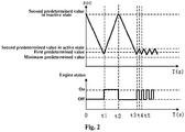
- Fig. 2 is a schematic diagram of a control strategy for switching between different driving modes of the control apparatus for a power follower and a power battery for an electric vehicle according to one embodiment of the present invention.
- T 0, the electric quantity of the power battery 1 is at the maximum value (max), and during the time 0 to t1, the driving mode is the first driving mode, and the electric quantity of the power battery 1 is gradually reduced to the first predetermined value.
- the electric quantity of the power battery 1 is at a first predetermined value, and the engine 21 is in a state for starting up, and when the electric quantity of the power battery 1 is less than the first predetermined value, the driving mode is switched to the second driving mode, and at this time, the power battery 1 stops operation, the engine 21 starts to operate and drive the electric generator 22 to generate power so as to simultaneously output electric power to drive the traction motor 5 and charge the power battery 1.
- the second predetermined value is substantially equal to the maximum value (max), and the power battery 1 can be substantially charged in the second driving mode to the fully charged state.
- the controller 3 controls the switch to the first driving mode, and the operating state during the time 0 to t1 is repeated.
- T t3
- the activation apparatus is in an active state, and at this time, the second predetermined value in the active state is the numerical value set by the driver according to the real-time requirements
- the power battery 1 is charged to the second predetermined value in the active state, and then the charging is stopped and meanwhile it is switched to the first driving mode.
- the power battery 1 operates alone to drive the rotation of the traction motor 5, and alternately switches between the first driving mode and the second driving mode, so that the power battery 1 is in a shallowly charged state.
- the first predetermined value is any percentage value within 18-24%.
- the second predetermined value is any percentage value within 82-100%.
- the second predetermined value is any percentage value within 25-82%.
- the present invention further sets the minimum electric quantity (min) of the power battery 1 to be any percentage value within 15-18%.
- the range of the electric quantity of charge and discharge of the power battery 1 is defined, so that the state of charge can always be within a prescribed range so as to prevent the state of charge of the battery from being too high or too low to prolong the battery life.
- the driving mode of the control apparatus of the present invention further comprises a third driving mode, and the power battery 1 and the power follower 2 simultaneously output electric power to drive the traction motor 5, wherein the controller 3 is configured to: select the third driving mode when the first driving mode or the second driving mode fails to meet the instantaneous power demand of the electric vehicle, and correspondingly return to the original first driving mode or second driving mode when the instantaneous power demand of the electric vehicle falls back. For example, during the driving of the vehicle, some special conditions, such as climbing a long ramp and/or sudden acceleration, may not be avoided.
- the controller controls the power battery 1 and the power follower 2 to operate in the third driving mode, so that the power battery 1 and the power follower 2 operate simultaneously to provide electric power to drive the traction motor 5.
- the controller 3 correspondingly controls the power battery 1 and the power follower 2 to return to the original first driving mode or second driving mode before the special condition.
- the power follower 2 and the power battery 1 are used as two energy output sources to provide power for the electric vehicle
- the power battery 1 is used as the main energy output source
- the controller 3 is used to realize the switching between different driving modes between the two energy output sources, i.e., the power follower 2 and the power battery 1
- the activation apparatus 4 is used to manually control the numerical value of the second predetermined value according to the requirement of a driver to control the quantity of charge of the power battery 1, thereby reducing the fuel consumption and improving the energy-saving performance.
- various predetermined values are provided to define the range of the electric quantity of charge and discharge of the power battery 1, so that the state of charge of the power battery is maintained within a prescribed range to prevent the state of charge of the battery state from being too high or too low so as to prolong the battery life.
- the present invention further provides a control method for a power follower and a power battery for an electric vehicle, the control method comprising the following steps:
- Fig. 3 is a schematic diagram of a control flow for switching between different driving modes of the control apparatus for a power follower and a power battery for an electric vehicle according to one embodiment of the present invention.
- a power battery 1 is used to output electric power to drive a traction motor 5 of the electric vehicle; and a power follower 2 is used to output electric power to drive the traction motor 5 of the electric vehicle and/or charge the power battery 1.
- the following steps are comprised:
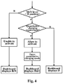
- Fig. 4 is a schematic diagram of a control flow for a driver of a control apparatus requesting a quantitative charging mode according to the requirement according to one embodiment of the present invention.
- the activation apparatus 4 is integrated at the shift lever of the vehicle.
- the activation apparatus 4 is an activation button C, which represents Charging, and can realize the quantitative charging of the battery.
- the activation button C has only two modes, ON/OFF, which respectively indicate being activated and inactivated, and is pressed to be ON and lifted to be OFF.
- the dashboard can also display the current status, such as gear position, whether it is charged, the charging percentage and other information. As shown in Fig.
Landscapes
- Engineering & Computer Science (AREA)
- Transportation (AREA)
- Mechanical Engineering (AREA)
- Life Sciences & Earth Sciences (AREA)
- Sustainable Development (AREA)
- Sustainable Energy (AREA)
- Power Engineering (AREA)
- Automation & Control Theory (AREA)
- Electric Propulsion And Braking For Vehicles (AREA)
- Charge And Discharge Circuits For Batteries Or The Like (AREA)
- Secondary Cells (AREA)
Description
- The present invention relates to the technical field of electric vehicles, in particular to a control apparatus and method for a power follower and a power battery for an electric vehicle.
-
DE 10 2016 102 930 A1 ,US 2013/0166125 A1 andUS 2011/0166733 A1 disclose different types of hybrid vehicles. - At present, as the requirements for fuel consumption and emissions of vehicles become more and more strict, an extended-range electric vehicle for reducing the fuel consumption of vehicle and reducing the emissions of vehicle has appeared on the market. For such extended-range electric vehicles, the energy supply is based on a power battery, and the power battery required is large in capacity and heavy in weight. The power follower serves as an auxiliary energy source, and when the remaining electric quantity (soc) ("soc" described herein is an abbreviation of "State of Charge", indicating the state of charge, that is, the state of battery power) of the power battery is less than a certain value, the power follower charges the power battery. The engine in the power follower operates efficiently at one or several fixed speed points, the power follower charges the power battery, and the battery outputs power to the traction motor to drive the vehicle. The power follower charges the power battery and the battery discharges to the traction motor, both of which will lose a certain amount of energy, and the frequent use of the power battery results in a reduced service life. The control strategy for the power follower and the power battery in the prior art has the problem of high fuel consumption and poor energy-saving performance.
-
US 2015/0191164 A1 describes a vehicle that has electrical motor generators and an internal combustion motor. A user can make a choice via a switch, whether use of the internal combustion motor shall be allowed or not. - An object of the present invention is to provide a control apparatus for a power follower and a power battery for an electric vehicle, to solve the problem of high-power consumption and poor energy-saving performance of the power follower and the power battery control strategy in the prior art.
- In particular, the present invention provides a control apparatus and method for a power follower and a power battery for an electric vehicle, the control apparatus comprising:
- a power battery used to output electric power to drive a traction motor of the electric vehicle;
- a power follower used to output electric power to drive the traction motor and/or charge the power battery;
- a controller used to control the driving modes of the power battery and the power follower, wherein the controller is configured to: select, when the remaining electric quantity of the power battery is not greater than a first predetermined value, a second driving mode until the remaining electric quantity of the power battery rises to a second predetermined value; select, when the remaining electric quantity of the power battery is not less than the second predetermined value, a first driving mode until the remaining electric quantity of the power battery is not greater than the first predetermined value; and alternately switch between the first driving mode and the second driving mode, the second predetermined value being greater than the first predetermined value; and
- an activation apparatus used to manually control the numerical value of second predetermined value according to the requirement of a driver,
- wherein the first driving mode is that the power battery operates alone to output electric power to drive the traction motor; and the second driving mode is that the power follower operates alone to output electric power to drive the traction motor and to charge the power battery.
- Further, the power follower comprises an engine and an electric generator.
- Further, the activation apparatus is disposed at a position in a vehicle center console, which position is convenient for the operation of a driver.
- Further, the activation apparatus comprises an inactive state and an active state, wherein, in the inactive state, the second predetermined value is an electric quantity when the power battery is substantially in a fully charged state; and in the active state, the second predetermined value is obtained by manual control according to the requirement of a driver.
- Further, in the inactive state, the second predetermined value is 82-100%.
- Further, in the active state, the second predetermined value is 25-82%.
- Further, the first predetermined value is 18-24%.
- Further, the driving mode further comprises a third driving mode in which the power battery and the power follower simultaneously output electric power to drive the traction motor;
wherein the controller is configured to: select the third driving mode when the first driving mode or the second driving mode fails to meet the instantaneous power demand of the electric vehicle, and correspondingly return to the original first driving mode or second driving mode when the instantaneous power demand of the electric vehicle falls back. - In particular, the present invention further provides a control method for a power follower and a power battery for an electric vehicle, the control method comprising the following steps:
- outputting electric power to drive a traction motor of the electric vehicle by using a power battery;
- outputting electric power to drive the traction motor of the electric vehicle and/or charge the power battery by using a power follower;
- controlling the driving mode of the power battery and the power follower by means of a controller, wherein the controller is configured to: select, when the remaining electric quantity of the power battery is not greater than a first predetermined value, a second driving mode until the remaining electric quantity of the power battery rises to a second predetermined value; select, when the remaining electric quantity of the power battery is not less than the second predetermined value, a first driving mode until the remaining electric quantity of the power battery is not greater than the first predetermined value; and alternately switch between the first driving mode and the second driving mode, the second predetermined value being greater than the first predetermined value; and wherein the first driving mode is that the power battery operates alone to output electric power to drive the traction motor; and the second driving mode is that the power follower operates alone to output electric power to drive the traction motor and to charge the power battery; and
- manually controlling the numerical value of the second predetermined value by means of an activation apparatus according to the requirement of a driver to control the quantity of charge of the power battery.
- Further, the driving mode further comprises a third driving mode in which the power battery and the power follower simultaneously output electric power to drive the traction motor;
wherein the controller is configured to: select the third driving mode when the first driving mode or the second driving mode fails to meet the instantaneous power demand of the electric vehicle, and correspondingly return to the original first driving mode or second driving mode when the instantaneous power demand of the electric vehicle falls back. - As to the control apparatus for a power follower and a power battery for an electric vehicle provided in the present invention, the power follower and the power battery are used as two energy output sources to provide power for the electric vehicle, the power battery is used as the main energy output source, the controller is used to realize the switching between different driving modes between the two energy output sources, i.e., the power follower and the power battery, and the activation apparatus is used to manually control the numerical value of the second predetermined value according to the requirement of a driver to control the quantity of charge of the power battery, thereby reducing the fuel consumption and improving the energy-saving performance.
- As to the control apparatus for a power follower and a power battery for an electric vehicle provided in the present invention, various predetermined values are provided to define the range of the electric quantity of charge and discharge of the power battery, so that the state of charge of the power battery is maintained within a prescribed range to prevent the state of charge of the battery state from being too high or too low so as to prolong the battery life.
- According to the detailed description of specific embodiments of the present invention below in conjunction with the accompanying drawings, the above and other purposes, advantages and features will become more apparent for a person skilled in the art.
- Some specific embodiments of the present invention will be described below in detail with reference to the accompanying drawings by way of example but not by way of limitation. The same reference signs indicate the same or similar components or parts in the accompanying drawings. It is understood by a person skilled in the art that the drawings are not drawn to scale necessarily. In the accompanying drawings:
-
Fig. 1 is a general structural block diagram of a control apparatus for a power follower and a power battery for an electric vehicle according to one embodiment of the present invention; -
Fig. 2 is a schematic diagram of a control strategy for switching between different driving modes of the control apparatus for a power follower and a power battery for an electric vehicle according to one embodiment of the present invention; -
Fig. 3 is a schematic diagram of a control flow for switching between different driving modes of the control apparatus for a power follower and a power battery for an electric vehicle according to one embodiment of the present invention; and -
Fig. 4 is a schematic diagram of a control flow for a driver of a control apparatus requesting a quantitative charging mode according to the requirement according to one embodiment of the present invention. -
Fig. 1 is a general structural block diagram of a power follower for an electric vehicle and a control apparatus for a power battery according to one embodiment of the present invention. As shown inFig. 1 , a control apparatus for a power follower and a power battery for an electric vehicle may comprises apower battery 1, apower follower 2, acontroller 3 and anactivation apparatus 4. Thepower battery 1 is used to output electric power to drive atraction motor 5 of the electric vehicle and further drive the rotation of wheels 6 of the electric vehicle. Thepower follower 2 comprises anengine 21 and anelectric generator 22 used to output electric power to drive thetraction motor 5 and/or charge thepower battery 1. Theengine 21 is connected to theelectric generator 22 so that theengine 21, when in operation, drives the rotation of theelectric generator 22 to generate electric power, and theengine 21 may use gasoline, diesel, natural gas and the other energy sources. Theelectric generator 22 is connected to thepower battery 1 to charge the power battery, and theelectric generator 22 is connected to thetraction motor 5 to output electric power to cause thetraction motor 5 to rotate. Thecontroller 3 is electrically connected to thepower follower 2 and the power battery for controlling the driving modes of thepower battery 1 and thepower follower 2; and multiple driving modes are provided, and thecontroller 3 controls thepower battery 1 and thepower follower 2 to select one mode to operate from the multiple driving modes. The multiple driving modes comprise a first driving mode and a second driving mode, wherein the first driving mode is that thepower battery 1 operates alone to output electric power to drive thetraction motor 5; and the second driving mode is that thepower follower 2 operates alone to output electric power to drive thetraction motor 5 and charge thepower battery 1. Thecontroller 3 is configured to: select, when the remaining electric quantity of the power battery is not greater than a first predetermined value, a second driving mode until the remaining electric quantity of thepower battery 1 rises to a second predetermined value; select, when the remaining electric quantity of thepower battery 1 is not less than the second predetermined value, a first driving mode until the remaining electric quantity of thepower battery 1 is not greater than the first predetermined value; and alternately switch between the first driving mode and the second driving mode, the second predetermined value being greater than the first predetermined value. Theactivation apparatus 4 is electrically connected to thecontroller 3 for manually controlling the numerical value of the second predetermined value according to the requirement of a driver so as to control the quantity of charge of thepower battery 1. - Specifically, in the first driving mode, the
power battery 1 operates alone to output electric power to drive thetraction motor 5, and at this time, thepower follower 2 is in a stop state. In the second driving mode, thepower follower 2 operates alone to output electric power to drive thetraction motor 5 while simultaneously charging thepower battery 1. At this time, thepower battery 1 is only in a charging state, and thepower battery 1 does not output power, so that thepower battery 1 can be charged as quickly as possible. In a particular embodiment, theactivation apparatus 4 is disposed at a position in a vehicle center console, which position is convenient for the operation of a driver, for example, can be disposed on a shift lever for ease of operation. More specifically, theactivation apparatus 4 may be a button or a switch with a rotary scale so as to control it to be in an active state or an inactive state. In the inactive state, the second predetermined value is set to be an electric quantity when thepower battery 1 is substantially in a fully charged state, and at this time, when the controller controls thepower battery 1 and thepower follower 2 to operate in the second driving mode, thepower battery 1 can be charged from the remaining electric quantity (soc) to a substantially fully charged state, and then thepower battery 1 and thepower follower 2 operates in the first driving mode again until the soc is not greater than the first predetermined value. When theactivation apparatus 4 is in an active state, that is, when the driver presses or opens theactivation apparatus 4 as needed, the second predetermined value is set to the numerical value selected by the driver, and at this time, when the controller controls thepower battery 1 and thepower follower 2 to operate in the second driving mode, thepower battery 1 is shallowly charged according to the real-time requirements of the driver only by charging thepower battery 1 from the remaining electric quantity (soc) to the numerical value of the second predetermined value selected by the driver, that is, by controlling thepower battery 1 and thepower follower 2 to operate in the first driving mode. The percentage of charge to the power battery depends on the real-time requirements of the driver and the numerical value of the second predetermined value set by the driver. For example, in a specific embodiment, when the driver has a self-charging requirement, if it is determined that the plug-in charging can be performed after half an hour, theactivation apparatus 4 can control the switch from the automatic full charging state to the quantitative shallow charging state of the battery, so that the quantity of charge is just enough to satisfy the power consumption for the next half hour to reduce the fuel consumption of theengine 21 and improve the energy-saving performance. -
Fig. 2 is a schematic diagram of a control strategy for switching between different driving modes of the control apparatus for a power follower and a power battery for an electric vehicle according to one embodiment of the present invention. As shown inFig. 2 , when T = 0, the electric quantity of thepower battery 1 is at the maximum value (max), and during thetime 0 to t1, the driving mode is the first driving mode, and the electric quantity of thepower battery 1 is gradually reduced to the first predetermined value. When T = t1, the electric quantity of thepower battery 1 is at a first predetermined value, and theengine 21 is in a state for starting up, and when the electric quantity of thepower battery 1 is less than the first predetermined value, the driving mode is switched to the second driving mode, and at this time, thepower battery 1 stops operation, theengine 21 starts to operate and drive theelectric generator 22 to generate power so as to simultaneously output electric power to drive thetraction motor 5 and charge thepower battery 1. At this time, if the activation apparatus is in an inactive state, during the time t1 to t2 as shown in the figure, the second predetermined value is substantially equal to the maximum value (max), and thepower battery 1 can be substantially charged in the second driving mode to the fully charged state. During the time t2 to t3, after thepower battery 1 is charged to the fully charged state, thecontroller 3 controls the switch to the first driving mode, and the operating state during thetime 0 to t1 is repeated. When T = t3, the activation apparatus is in an active state, and at this time, the second predetermined value in the active state is the numerical value set by the driver according to the real-time requirements, and during the time t3 to t4, in the second driving mode, thepower battery 1 is charged to the second predetermined value in the active state, and then the charging is stopped and meanwhile it is switched to the first driving mode. During the time t4 to t5, in the first driving mode, thepower battery 1 operates alone to drive the rotation of thetraction motor 5, and alternately switches between the first driving mode and the second driving mode, so that thepower battery 1 is in a shallowly charged state. - In a preferred embodiment, the first predetermined value is any percentage value within 18-24%. When the
activation apparatus 4 is in the inactive state, the second predetermined value is any percentage value within 82-100%. When theactivation apparatus 4 is in the active state, the second predetermined value is any percentage value within 25-82%. The present invention further sets the minimum electric quantity (min) of thepower battery 1 to be any percentage value within 15-18%. During charging and discharging of thepower battery 1, the range of the electric quantity of charge and discharge of thepower battery 1 is defined, so that the state of charge can always be within a prescribed range so as to prevent the state of charge of the battery from being too high or too low to prolong the battery life. - Further, The driving mode of the control apparatus of the present invention further comprises a third driving mode, and the
power battery 1 and thepower follower 2 simultaneously output electric power to drive thetraction motor 5, wherein thecontroller 3 is configured to: select the third driving mode when the first driving mode or the second driving mode fails to meet the instantaneous power demand of the electric vehicle, and correspondingly return to the original first driving mode or second driving mode when the instantaneous power demand of the electric vehicle falls back. For example, during the driving of the vehicle, some special conditions, such as climbing a long ramp and/or sudden acceleration, may not be avoided. At this time, the power demand of the entire vehicle cannot be satisfied when the driving mode is the first driving mode or the second driving mode, and the controller controls thepower battery 1 and thepower follower 2 to operate in the third driving mode, so that thepower battery 1 and thepower follower 2 operate simultaneously to provide electric power to drive thetraction motor 5. Also, after a special condition, such as climbing a long ramp and/or a sudden acceleration disappears, when the instantaneous power demand of the electric vehicle can be satisfied in the first driving mode or the second driving mode, thecontroller 3 correspondingly controls thepower battery 1 and thepower follower 2 to return to the original first driving mode or second driving mode before the special condition. - As to the control apparatus for a power follower and a power battery for an electric vehicle provided in the present invention, the
power follower 2 and thepower battery 1 are used as two energy output sources to provide power for the electric vehicle, thepower battery 1 is used as the main energy output source, thecontroller 3 is used to realize the switching between different driving modes between the two energy output sources, i.e., thepower follower 2 and thepower battery 1, and theactivation apparatus 4 is used to manually control the numerical value of the second predetermined value according to the requirement of a driver to control the quantity of charge of thepower battery 1, thereby reducing the fuel consumption and improving the energy-saving performance. - As to the control apparatus for a power follower and a power battery for an electric vehicle provided in the present invention, various predetermined values are provided to define the range of the electric quantity of charge and discharge of the
power battery 1, so that the state of charge of the power battery is maintained within a prescribed range to prevent the state of charge of the battery state from being too high or too low so as to prolong the battery life. - The present invention further provides a control method for a power follower and a power battery for an electric vehicle, the control method comprising the following steps:
- outputting electric power to drive a
traction motor 5 of the electric vehicle by using apower battery 1; - outputting electric power to drive the
traction motor 5 of the electric vehicle and/or charge thepower battery 1 by using apower follower 2; - controlling the driving mode of the
power battery 1 and thepower follower 2 by means of acontroller 3, wherein thecontroller 3 is configured to: select, when the remaining electric quantity of thepower battery 1 is not greater than a first predetermined value, a second driving mode until the remaining electric quantity of thepower battery 1 rises to a second predetermined value; select, when the remaining electric quantity of thepower battery 1 is not less than the second predetermined value, a first driving mode until the remaining electric quantity of thepower battery 1 is not greater than the first predetermined value; and alternately switch between the first driving mode and the second driving mode, the second predetermined value being greater than the first predetermined value; and wherein the first driving mode is that thepower battery 1 operates alone to output electric power to drive thetraction motor 5; and the second driving mode is that thepower follower 2 operates alone to output electric power to drive thetraction motor 5 and charge thepower battery 1; and - the numerical value of the second predetermined value is manually controlled by means of an
activation apparatus 4 according to the requirement of a driver to control the quantity of charge of thepower battery 1. - Further, the driving mode further comprises a third driving mode in which the power battery and the power follower simultaneously output electric power to drive the traction motor;
- wherein the
controller 3 is configured to: select the third driving mode when the first driving mode or the second driving mode fails to meet the instantaneous power demand of the electric vehicle, and correspondingly return to the original first driving mode or second driving mode when the instantaneous power demand of the electric vehicle falls back. -
Fig. 3 is a schematic diagram of a control flow for switching between different driving modes of the control apparatus for a power follower and a power battery for an electric vehicle according to one embodiment of the present invention. As shown inFig. 3 , apower battery 1 is used to output electric power to drive atraction motor 5 of the electric vehicle; and apower follower 2 is used to output electric power to drive thetraction motor 5 of the electric vehicle and/or charge thepower battery 1. The following steps are comprised: - Step 1: the vehicle is driven by the
power battery 1. - Step 2: when the electric quantity of the
power battery 1 drops to a first predetermined value (the first predetermined value > the minimum value (min) set by the soc, to avoid damage to the battery caused by excessive discharge), the engine is started for power supply, and the power supplying from the battery is stopped. At this time: <1> if the driver does not need to charge the battery, that is, theactivation apparatus 4 is not activated, the battery is automatically controlled to be charged to the second predetermined value in the active state (which is substantially equal to the maximum value (max) set by the soc), andstep 3 is executed next. <2> If the driver has a self-charging requirement, that is, theactivation apparatus 4 is activated, for example, it is determined that the plug-in charging can be performed after half an hour, theactivation apparatus 4 designed on a shift lever can be used to switch from the automatic full charging state to the quantitative shallow charging state of the battery, andstep 4 is executed next. At the same time, this function should be informed in the operating instruction manual of the vehicle. - Step 3: when the SOC ≥ the maximum value (max), the
engine 21 is stopped, andstep 1 is repeated. - Step 4: when the SOC ≥ the second predetermined value, the
engine 21 is stopped, andstep 1 is repeated. -
Fig. 4 is a schematic diagram of a control flow for a driver of a control apparatus requesting a quantitative charging mode according to the requirement according to one embodiment of the present invention. As shown inFig. 4 , theactivation apparatus 4 is integrated at the shift lever of the vehicle. In a specific embodiment, theactivation apparatus 4 is an activation button C, which represents Charging, and can realize the quantitative charging of the battery. The activation button C has only two modes, ON/OFF, which respectively indicate being activated and inactivated, and is pressed to be ON and lifted to be OFF. Preferably, the dashboard can also display the current status, such as gear position, whether it is charged, the charging percentage and other information. As shown inFig. 4 , only when the position of the shift lever is in the D position (forward gear), the driver is allowed to activate the button, and at the same time the dashboard displays that the current status is D position and quantitative charging C is carried out; if the button is not activated, the dashboard only displays running in the D position; otherwise, the dashboard displays a non-D position (that is, R/N gear position, i.e., reverse gear or neutral position). At the same time, this function should be informed in the operating instruction manual of the vehicle. - So far, it is recognized by a person skilled in the art that although multiple exemplary embodiments of the present invention have been shown and described in detail herein, many other variations or modifications complying with the principles of the present invention can be directly determined or derived from the contents disclosed in the present invention.
Claims (10)
- A control apparatus for a power follower (2) and a power battery (1) for an electric vehicle, the control apparatus comprising:a power battery (1) used to output electric power to drive a traction motor (5) of the electric vehicle;a power follower (2) used to output electric power to drive the traction motor (5) and/or charge the power battery (1);a controller (3) used to control the driving modes of the power battery (1) and the power follower (2), wherein the controller (3) is configured to: select, when the remaining electric quantity (soc) of the power battery (1) is not greater than a first predetermined value, a second driving mode until the remaining electric quantity (soc) of the power battery (1) rises to a second predetermined value; select, when the remaining electric quantity (soc) of the power battery is not less than the second predetermined value, a first driving mode until the remaining electric quantity (soc) of the power battery (1) is not greater than the first predetermined value; and alternately switch between the first driving mode and the second driving mode, the second predetermined value being greater than the first predetermined value; andan activation apparatus (4) used to manually control the numerical value of the second predetermined value according to the requirement of a driver;wherein the first driving mode is that the power battery (1) operates alone to output electric power to drive the traction motor (5); and the second driving mode is that the power follower (2) operates alone to output electric power to drive the traction motor (5) and to charge the power battery (1).
- The control apparatus according to claim 1, wherein the power follower (2) comprises an engine (21) and an electric generator (22).
- The control apparatus according to claim 1, wherein the activation apparatus (4) is disposed at a position in a vehicle center console, which position is convenient for the operation of a driver.
- The control apparatus according to any one of claims 1 to 3, wherein the activation apparatus (4) comprises an inactive state and an active state; and wherein, in the inactive state, the second predetermined value is an electric quantity when the power battery is in a fully charged state; and in the active state, the second predetermined value is obtained by manual control according to the requirement of a driver.
- The control apparatus according to claim 4, wherein, in the inactive state, the second predetermined value is 82-100%.
- The control apparatus according to claim 4, wherein, in the active state, the second predetermined value is 25-82%.
- The control apparatus according to claim 1, wherein the first predetermined value is 18-24%.
- The control apparatus according to claim 1, wherein the driving mode further comprises a third driving mode in which the power battery (1) and the power follower (2) simultaneously output electric power to drive the traction motor (5);
wherein the controller (3) is configured to: select the third driving mode when the first driving mode or the second driving mode fails to meet the instantaneous power demand of the electric vehicle, and correspondingly return to the original first driving mode or second driving mode when the instantaneous power demand of the electric vehicle falls back. - A control method for a power follower (2) and a power battery (1) for an electric vehicle, the control method comprising the following steps:outputting electric power to drive a traction motor (5) of the electric vehicle by using a power battery (1);outputting electric power to drive the traction motor (5) of the electric vehicle and/or charge the power battery (1) by using a power follower (2);controlling the driving modes of the power battery (1) and the power follower (2) by means of a controller (3), wherein the controller (3) is configured to: select, when the remaining electric quantity (soc) of the power battery (1) is not greater than a first predetermined value, a second driving mode until the remaining electric quantity (soc) of the power battery (1) rises to a second predetermined value; select, when the remaining electric quantity (soc) of the power battery (1) is not less than the second predetermined value, a first driving mode until the remaining electric quantity (soc) of the power battery (1) is not greater than the first predetermined value; and alternately switch between the first driving mode and the second driving mode, the second predetermined value being greater than the first predetermined value; and wherein the first driving mode is that the power battery (1) operates alone to output electric power to drive the traction motor (5); and the second driving mode is that the power follower (2) operates alone to output electric power to drive the traction motor (5) and to charge the power battery (1); andmanually controlling the numerical value of the second predetermined value by means of an activation apparatus (4) according to the requirement of a driver to control the quantity of charge of the power battery (1).
- The control method according to claim 9, wherein the driving mode further comprises a third driving mode in which the power battery (1) and the power follower (2) simultaneously output electric power to drive the traction motor (5);
wherein the controller (3) is configured to: select the third driving mode when the first driving mode or the second driving mode fails to meet the instantaneous power demand of the electric vehicle, and correspondingly return to the original first driving mode or second driving mode when the instantaneous power demand of the electric vehicle falls back.
Applications Claiming Priority (2)
| Application Number | Priority Date | Filing Date | Title |
|---|---|---|---|
| CN201610887401.2A CN106347145B (en) | 2016-10-11 | 2016-10-11 | For the power follower of electric vehicle and the control device and method of power battery |
| PCT/CN2017/100514 WO2018068595A1 (en) | 2016-10-11 | 2017-09-05 | Power follower for electric vehicle, and control apparatus and method for power battery |
Publications (3)
| Publication Number | Publication Date |
|---|---|
| EP3505386A1 EP3505386A1 (en) | 2019-07-03 |
| EP3505386A4 EP3505386A4 (en) | 2019-08-28 |
| EP3505386B1 true EP3505386B1 (en) | 2021-03-10 |
Family
ID=57866745
Family Applications (1)
| Application Number | Title | Priority Date | Filing Date |
|---|---|---|---|
| EP17860350.2A Not-in-force EP3505386B1 (en) | 2016-10-11 | 2017-09-05 | Power follower for electric vehicle, and control apparatus and method for power battery |
Country Status (3)
| Country | Link |
|---|---|
| EP (1) | EP3505386B1 (en) |
| CN (1) | CN106347145B (en) |
| WO (1) | WO2018068595A1 (en) |
Families Citing this family (10)
| Publication number | Priority date | Publication date | Assignee | Title |
|---|---|---|---|---|
| CN106541940B (en) * | 2016-10-11 | 2019-03-19 | 浙江吉利新能源商用车有限公司 | A kind of power source for electric vehicle and power source selection method |
| CN106347145B (en) * | 2016-10-11 | 2018-12-25 | 浙江吉利新能源商用车有限公司 | For the power follower of electric vehicle and the control device and method of power battery |
| CN110254254A (en) * | 2019-02-23 | 2019-09-20 | 福爱电子(贵州)有限公司 | A kind of low-speed electronic vehicle distance increasing unit control system and method |
| CN112659982B (en) * | 2020-04-03 | 2022-10-11 | 长城汽车股份有限公司 | Energy management method and battery control system for plug-in fuel cell vehicle |
| CN112277728B (en) * | 2020-10-30 | 2024-12-03 | 东风汽车集团有限公司 | A power control system and method for extended-range vehicle |
| CN112319248B (en) * | 2020-11-17 | 2022-04-26 | 睿驰电装(大连)电动系统有限公司 | Method and device for controlling starting of engine of extended range electric vehicle |
| CN112644502A (en) * | 2020-12-31 | 2021-04-13 | 大运汽车股份有限公司 | Control method suitable for driving mode switching of new energy commercial vehicle |
| CN114506246B (en) * | 2022-03-15 | 2023-04-18 | 厦门金龙联合汽车工业有限公司 | Time-sharing control method of power battery power conversion system of electric automobile |
| CN115742863B (en) * | 2022-10-25 | 2024-11-29 | 中车永济电机有限公司 | Multi-group power battery hybrid power supply control logic method suitable for hybrid power locomotive |
| CN116160875B (en) * | 2023-04-23 | 2023-07-18 | 新誉轨道交通科技有限公司 | Control method and control device for range extender system |
Family Cites Families (14)
| Publication number | Priority date | Publication date | Assignee | Title |
|---|---|---|---|---|
| CN1311999C (en) * | 2005-01-31 | 2007-04-25 | 上海汽车工业(集团)总公司汽车工程研究院 | Parallel connection mixed power driving system and its driving method |
| CN101468610B (en) * | 2007-12-28 | 2011-03-30 | 比亚迪股份有限公司 | A charging control device and method for a hybrid vehicle |
| JP5359621B2 (en) * | 2009-07-03 | 2013-12-04 | トヨタ自動車株式会社 | Fuel cell system and control method thereof |
| US9764632B2 (en) * | 2010-01-07 | 2017-09-19 | Ford Global Technologies, Llc | Plug-in hybrid electric vehicle battery state of charge hold function and energy management |
| JP5712915B2 (en) * | 2011-12-21 | 2015-05-07 | トヨタ自動車株式会社 | Plug-in hybrid vehicle |
| BR112014032945A2 (en) * | 2012-08-31 | 2017-06-27 | Toyota Motor Co Ltd | vehicle and vehicle control method |
| CN103419675B (en) * | 2013-09-05 | 2015-12-09 | 安徽江淮汽车股份有限公司 | A kind of operating method of stroke-increasing electric automobile |
| US20150217755A1 (en) * | 2014-02-05 | 2015-08-06 | Ford Global Technologies, Llc | Vehicle energy management system and method |
| CN104163114B (en) * | 2014-07-22 | 2016-06-08 | 浙江大学 | A kind of car load energy management method for internal combustion power generating mileage increasing type electric vehicle |
| JP6068531B2 (en) * | 2015-02-23 | 2017-01-25 | 富士重工業株式会社 | SOC display device for hybrid vehicle |
| CN206436841U (en) * | 2016-10-11 | 2017-08-25 | 浙江吉利新能源商用车有限公司 | Power follower and the control device of electrokinetic cell for electric vehicle |
| CN106541940B (en) * | 2016-10-11 | 2019-03-19 | 浙江吉利新能源商用车有限公司 | A kind of power source for electric vehicle and power source selection method |
| CN106347145B (en) * | 2016-10-11 | 2018-12-25 | 浙江吉利新能源商用车有限公司 | For the power follower of electric vehicle and the control device and method of power battery |
| CN106347358B (en) * | 2016-10-11 | 2019-03-19 | 浙江吉利新能源商用车有限公司 | A kind of power source for electric vehicle and power source switching control method |
-
2016
- 2016-10-11 CN CN201610887401.2A patent/CN106347145B/en active Active
-
2017
- 2017-09-05 WO PCT/CN2017/100514 patent/WO2018068595A1/en not_active Ceased
- 2017-09-05 EP EP17860350.2A patent/EP3505386B1/en not_active Not-in-force
Non-Patent Citations (1)
| Title |
|---|
| None * |
Also Published As
| Publication number | Publication date |
|---|---|
| EP3505386A1 (en) | 2019-07-03 |
| CN106347145A (en) | 2017-01-25 |
| CN106347145B (en) | 2018-12-25 |
| EP3505386A4 (en) | 2019-08-28 |
| WO2018068595A1 (en) | 2018-04-19 |
Similar Documents
| Publication | Publication Date | Title |
|---|---|---|
| EP3505386B1 (en) | Power follower for electric vehicle, and control apparatus and method for power battery | |
| CN114290916B (en) | Energy management method and system for hydrogen fuel hybrid power heavy truck | |
| CN109334476B (en) | A fuel cell vehicle control system and control method | |
| US8140204B2 (en) | Charge depleting energy management strategy for plug-in hybrid electric vehicles | |
| JP4020646B2 (en) | Control method of hybrid electric vehicle | |
| CN108146254B (en) | Control method and device of range extender | |
| US8676418B2 (en) | Control system and control method | |
| EP2262672B1 (en) | Battery pack management strategy in a hybrid electric motor vehicle | |
| CN103879399B (en) | The driving mode switch controller of motor vehicle driven by mixed power | |
| KR100916428B1 (en) | Auxiliary Battery Charging Control Method for Hybrid Vehicle | |
| US20180233943A1 (en) | Power supply system for vehicle | |
| EP3045367A1 (en) | Control system and method for hybrid vehicle | |
| CN104955699A (en) | Hybrid vehicle | |
| WO2011000259A1 (en) | Control method for generator set of electric vehicle | |
| CN106347358B (en) | A kind of power source for electric vehicle and power source switching control method | |
| JP2009247057A (en) | Electric vehicle control device | |
| JP2013086529A (en) | Power control device of hybrid vehicle | |
| JP2004084484A (en) | Vehicle control device | |
| JP2023031954A (en) | Fuel-cell vehicle | |
| CN103339006B (en) | Motor vehicle driven by mixed power | |
| US12594926B2 (en) | System and method for power allocation to high-voltage thermal loads from multiple energy sources in a hybrid powertrain during cold conditions | |
| JP5310640B2 (en) | Drive device | |
| CN206436841U (en) | Power follower and the control device of electrokinetic cell for electric vehicle | |
| CN116674424B (en) | Vehicle power supply methods and systems, non-volatile storage media and vehicles | |
| CN109149679A (en) | Improve method, power source management controller and the automobile of electric car course continuation mileage |
Legal Events
| Date | Code | Title | Description |
|---|---|---|---|
| STAA | Information on the status of an ep patent application or granted ep patent |
Free format text: STATUS: THE INTERNATIONAL PUBLICATION HAS BEEN MADE |
|
| PUAI | Public reference made under article 153(3) epc to a published international application that has entered the european phase |
Free format text: ORIGINAL CODE: 0009012 |
|
| STAA | Information on the status of an ep patent application or granted ep patent |
Free format text: STATUS: REQUEST FOR EXAMINATION WAS MADE |
|
| 17P | Request for examination filed |
Effective date: 20190327 |
|
| AK | Designated contracting states |
Kind code of ref document: A1 Designated state(s): AL AT BE BG CH CY CZ DE DK EE ES FI FR GB GR HR HU IE IS IT LI LT LU LV MC MK MT NL NO PL PT RO RS SE SI SK SM TR |
|
| AX | Request for extension of the european patent |
Extension state: BA ME |
|
| STAA | Information on the status of an ep patent application or granted ep patent |
Free format text: STATUS: EXAMINATION IS IN PROGRESS |
|
| A4 | Supplementary search report drawn up and despatched |
Effective date: 20190729 |
|
| RIC1 | Information provided on ipc code assigned before grant |
Ipc: B60L 58/13 20190101AFI20190723BHEP |
|
| 17Q | First examination report despatched |
Effective date: 20190812 |
|
| DAV | Request for validation of the european patent (deleted) | ||
| DAX | Request for extension of the european patent (deleted) | ||
| REG | Reference to a national code |
Ref country code: DE Ref legal event code: R079 Ref document number: 602017034538 Country of ref document: DE Free format text: PREVIOUS MAIN CLASS: B60L0011120000 Ipc: B60L0050610000 |
|
| RIC1 | Information provided on ipc code assigned before grant |
Ipc: B60L 50/60 20190101ALI20200723BHEP Ipc: B60L 50/61 20190101AFI20200723BHEP Ipc: B60L 58/13 20190101ALI20200723BHEP |
|
| GRAP | Despatch of communication of intention to grant a patent |
Free format text: ORIGINAL CODE: EPIDOSNIGR1 |
|
| STAA | Information on the status of an ep patent application or granted ep patent |
Free format text: STATUS: GRANT OF PATENT IS INTENDED |
|
| INTG | Intention to grant announced |
Effective date: 20201001 |
|
| GRAS | Grant fee paid |
Free format text: ORIGINAL CODE: EPIDOSNIGR3 |
|
| GRAA | (expected) grant |
Free format text: ORIGINAL CODE: 0009210 |
|
| STAA | Information on the status of an ep patent application or granted ep patent |
Free format text: STATUS: THE PATENT HAS BEEN GRANTED |
|
| AK | Designated contracting states |
Kind code of ref document: B1 Designated state(s): AL AT BE BG CH CY CZ DE DK EE ES FI FR GB GR HR HU IE IS IT LI LT LU LV MC MK MT NL NO PL PT RO RS SE SI SK SM TR |
|
| REG | Reference to a national code |
Ref country code: GB Ref legal event code: FG4D |
|
| REG | Reference to a national code |
Ref country code: AT Ref legal event code: REF Ref document number: 1369457 Country of ref document: AT Kind code of ref document: T Effective date: 20210315 Ref country code: CH Ref legal event code: EP |
|
| REG | Reference to a national code |
Ref country code: IE Ref legal event code: FG4D |
|
| REG | Reference to a national code |
Ref country code: DE Ref legal event code: R096 Ref document number: 602017034538 Country of ref document: DE |
|
| REG | Reference to a national code |
Ref country code: LT Ref legal event code: MG9D |
|
| PG25 | Lapsed in a contracting state [announced via postgrant information from national office to epo] |
Ref country code: LT Free format text: LAPSE BECAUSE OF FAILURE TO SUBMIT A TRANSLATION OF THE DESCRIPTION OR TO PAY THE FEE WITHIN THE PRESCRIBED TIME-LIMIT Effective date: 20210310 Ref country code: BG Free format text: LAPSE BECAUSE OF FAILURE TO SUBMIT A TRANSLATION OF THE DESCRIPTION OR TO PAY THE FEE WITHIN THE PRESCRIBED TIME-LIMIT Effective date: 20210610 Ref country code: GR Free format text: LAPSE BECAUSE OF FAILURE TO SUBMIT A TRANSLATION OF THE DESCRIPTION OR TO PAY THE FEE WITHIN THE PRESCRIBED TIME-LIMIT Effective date: 20210611 Ref country code: HR Free format text: LAPSE BECAUSE OF FAILURE TO SUBMIT A TRANSLATION OF THE DESCRIPTION OR TO PAY THE FEE WITHIN THE PRESCRIBED TIME-LIMIT Effective date: 20210310 Ref country code: FI Free format text: LAPSE BECAUSE OF FAILURE TO SUBMIT A TRANSLATION OF THE DESCRIPTION OR TO PAY THE FEE WITHIN THE PRESCRIBED TIME-LIMIT Effective date: 20210310 Ref country code: NO Free format text: LAPSE BECAUSE OF FAILURE TO SUBMIT A TRANSLATION OF THE DESCRIPTION OR TO PAY THE FEE WITHIN THE PRESCRIBED TIME-LIMIT Effective date: 20210610 |
|
| REG | Reference to a national code |
Ref country code: AT Ref legal event code: MK05 Ref document number: 1369457 Country of ref document: AT Kind code of ref document: T Effective date: 20210310 |
|
| REG | Reference to a national code |
Ref country code: NL Ref legal event code: MP Effective date: 20210310 |
|
| PG25 | Lapsed in a contracting state [announced via postgrant information from national office to epo] |
Ref country code: SE Free format text: LAPSE BECAUSE OF FAILURE TO SUBMIT A TRANSLATION OF THE DESCRIPTION OR TO PAY THE FEE WITHIN THE PRESCRIBED TIME-LIMIT Effective date: 20210310 Ref country code: RS Free format text: LAPSE BECAUSE OF FAILURE TO SUBMIT A TRANSLATION OF THE DESCRIPTION OR TO PAY THE FEE WITHIN THE PRESCRIBED TIME-LIMIT Effective date: 20210310 Ref country code: LV Free format text: LAPSE BECAUSE OF FAILURE TO SUBMIT A TRANSLATION OF THE DESCRIPTION OR TO PAY THE FEE WITHIN THE PRESCRIBED TIME-LIMIT Effective date: 20210310 |
|
| PG25 | Lapsed in a contracting state [announced via postgrant information from national office to epo] |
Ref country code: NL Free format text: LAPSE BECAUSE OF FAILURE TO SUBMIT A TRANSLATION OF THE DESCRIPTION OR TO PAY THE FEE WITHIN THE PRESCRIBED TIME-LIMIT Effective date: 20210310 |
|
| PG25 | Lapsed in a contracting state [announced via postgrant information from national office to epo] |
Ref country code: EE Free format text: LAPSE BECAUSE OF FAILURE TO SUBMIT A TRANSLATION OF THE DESCRIPTION OR TO PAY THE FEE WITHIN THE PRESCRIBED TIME-LIMIT Effective date: 20210310 Ref country code: CZ Free format text: LAPSE BECAUSE OF FAILURE TO SUBMIT A TRANSLATION OF THE DESCRIPTION OR TO PAY THE FEE WITHIN THE PRESCRIBED TIME-LIMIT Effective date: 20210310 Ref country code: SM Free format text: LAPSE BECAUSE OF FAILURE TO SUBMIT A TRANSLATION OF THE DESCRIPTION OR TO PAY THE FEE WITHIN THE PRESCRIBED TIME-LIMIT Effective date: 20210310 Ref country code: AT Free format text: LAPSE BECAUSE OF FAILURE TO SUBMIT A TRANSLATION OF THE DESCRIPTION OR TO PAY THE FEE WITHIN THE PRESCRIBED TIME-LIMIT Effective date: 20210310 |
|
| PG25 | Lapsed in a contracting state [announced via postgrant information from national office to epo] |
Ref country code: IS Free format text: LAPSE BECAUSE OF FAILURE TO SUBMIT A TRANSLATION OF THE DESCRIPTION OR TO PAY THE FEE WITHIN THE PRESCRIBED TIME-LIMIT Effective date: 20210710 Ref country code: RO Free format text: LAPSE BECAUSE OF FAILURE TO SUBMIT A TRANSLATION OF THE DESCRIPTION OR TO PAY THE FEE WITHIN THE PRESCRIBED TIME-LIMIT Effective date: 20210310 Ref country code: SK Free format text: LAPSE BECAUSE OF FAILURE TO SUBMIT A TRANSLATION OF THE DESCRIPTION OR TO PAY THE FEE WITHIN THE PRESCRIBED TIME-LIMIT Effective date: 20210310 Ref country code: PT Free format text: LAPSE BECAUSE OF FAILURE TO SUBMIT A TRANSLATION OF THE DESCRIPTION OR TO PAY THE FEE WITHIN THE PRESCRIBED TIME-LIMIT Effective date: 20210712 Ref country code: PL Free format text: LAPSE BECAUSE OF FAILURE TO SUBMIT A TRANSLATION OF THE DESCRIPTION OR TO PAY THE FEE WITHIN THE PRESCRIBED TIME-LIMIT Effective date: 20210310 |
|
| REG | Reference to a national code |
Ref country code: DE Ref legal event code: R097 Ref document number: 602017034538 Country of ref document: DE |
|
| PLBE | No opposition filed within time limit |
Free format text: ORIGINAL CODE: 0009261 |
|
| STAA | Information on the status of an ep patent application or granted ep patent |
Free format text: STATUS: NO OPPOSITION FILED WITHIN TIME LIMIT |
|
| PG25 | Lapsed in a contracting state [announced via postgrant information from national office to epo] |
Ref country code: ES Free format text: LAPSE BECAUSE OF FAILURE TO SUBMIT A TRANSLATION OF THE DESCRIPTION OR TO PAY THE FEE WITHIN THE PRESCRIBED TIME-LIMIT Effective date: 20210310 Ref country code: DK Free format text: LAPSE BECAUSE OF FAILURE TO SUBMIT A TRANSLATION OF THE DESCRIPTION OR TO PAY THE FEE WITHIN THE PRESCRIBED TIME-LIMIT Effective date: 20210310 Ref country code: AL Free format text: LAPSE BECAUSE OF FAILURE TO SUBMIT A TRANSLATION OF THE DESCRIPTION OR TO PAY THE FEE WITHIN THE PRESCRIBED TIME-LIMIT Effective date: 20210310 |
|
| 26N | No opposition filed |
Effective date: 20211213 |
|
| PG25 | Lapsed in a contracting state [announced via postgrant information from national office to epo] |
Ref country code: SI Free format text: LAPSE BECAUSE OF FAILURE TO SUBMIT A TRANSLATION OF THE DESCRIPTION OR TO PAY THE FEE WITHIN THE PRESCRIBED TIME-LIMIT Effective date: 20210310 |
|
| REG | Reference to a national code |
Ref country code: DE Ref legal event code: R119 Ref document number: 602017034538 Country of ref document: DE |
|
| PG25 | Lapsed in a contracting state [announced via postgrant information from national office to epo] |
Ref country code: IT Free format text: LAPSE BECAUSE OF FAILURE TO SUBMIT A TRANSLATION OF THE DESCRIPTION OR TO PAY THE FEE WITHIN THE PRESCRIBED TIME-LIMIT Effective date: 20210310 |
|
| REG | Reference to a national code |
Ref country code: CH Ref legal event code: PL |
|
| REG | Reference to a national code |
Ref country code: BE Ref legal event code: MM Effective date: 20210930 |
|
| GBPC | Gb: european patent ceased through non-payment of renewal fee |
Effective date: 20210905 |
|
| PG25 | Lapsed in a contracting state [announced via postgrant information from national office to epo] |
Ref country code: IS Free format text: LAPSE BECAUSE OF FAILURE TO SUBMIT A TRANSLATION OF THE DESCRIPTION OR TO PAY THE FEE WITHIN THE PRESCRIBED TIME-LIMIT Effective date: 20210710 Ref country code: MC Free format text: LAPSE BECAUSE OF FAILURE TO SUBMIT A TRANSLATION OF THE DESCRIPTION OR TO PAY THE FEE WITHIN THE PRESCRIBED TIME-LIMIT Effective date: 20210310 |
|
| PG25 | Lapsed in a contracting state [announced via postgrant information from national office to epo] |
Ref country code: LU Free format text: LAPSE BECAUSE OF NON-PAYMENT OF DUE FEES Effective date: 20210905 Ref country code: IE Free format text: LAPSE BECAUSE OF NON-PAYMENT OF DUE FEES Effective date: 20210905 Ref country code: GB Free format text: LAPSE BECAUSE OF NON-PAYMENT OF DUE FEES Effective date: 20210905 Ref country code: FR Free format text: LAPSE BECAUSE OF NON-PAYMENT OF DUE FEES Effective date: 20210930 Ref country code: DE Free format text: LAPSE BECAUSE OF NON-PAYMENT OF DUE FEES Effective date: 20220401 Ref country code: BE Free format text: LAPSE BECAUSE OF NON-PAYMENT OF DUE FEES Effective date: 20210930 |
|
| PG25 | Lapsed in a contracting state [announced via postgrant information from national office to epo] |
Ref country code: LI Free format text: LAPSE BECAUSE OF NON-PAYMENT OF DUE FEES Effective date: 20210930 Ref country code: CH Free format text: LAPSE BECAUSE OF NON-PAYMENT OF DUE FEES Effective date: 20210930 |
|
| PG25 | Lapsed in a contracting state [announced via postgrant information from national office to epo] |
Ref country code: CY Free format text: LAPSE BECAUSE OF FAILURE TO SUBMIT A TRANSLATION OF THE DESCRIPTION OR TO PAY THE FEE WITHIN THE PRESCRIBED TIME-LIMIT Effective date: 20210310 |
|
| PG25 | Lapsed in a contracting state [announced via postgrant information from national office to epo] |
Ref country code: HU Free format text: LAPSE BECAUSE OF FAILURE TO SUBMIT A TRANSLATION OF THE DESCRIPTION OR TO PAY THE FEE WITHIN THE PRESCRIBED TIME-LIMIT; INVALID AB INITIO Effective date: 20170905 |
|
| PG25 | Lapsed in a contracting state [announced via postgrant information from national office to epo] |
Ref country code: MK Free format text: LAPSE BECAUSE OF FAILURE TO SUBMIT A TRANSLATION OF THE DESCRIPTION OR TO PAY THE FEE WITHIN THE PRESCRIBED TIME-LIMIT Effective date: 20210310 |
|
| PG25 | Lapsed in a contracting state [announced via postgrant information from national office to epo] |
Ref country code: MT Free format text: LAPSE BECAUSE OF FAILURE TO SUBMIT A TRANSLATION OF THE DESCRIPTION OR TO PAY THE FEE WITHIN THE PRESCRIBED TIME-LIMIT Effective date: 20210310 |
|
| PG25 | Lapsed in a contracting state [announced via postgrant information from national office to epo] |
Ref country code: TR Free format text: LAPSE BECAUSE OF FAILURE TO SUBMIT A TRANSLATION OF THE DESCRIPTION OR TO PAY THE FEE WITHIN THE PRESCRIBED TIME-LIMIT Effective date: 20210310 |