EP3505336A1 - Article with electronic component inclusion and method of manufacturing - Google Patents
Article with electronic component inclusion and method of manufacturing Download PDFInfo
- Publication number
- EP3505336A1 EP3505336A1 EP18213551.7A EP18213551A EP3505336A1 EP 3505336 A1 EP3505336 A1 EP 3505336A1 EP 18213551 A EP18213551 A EP 18213551A EP 3505336 A1 EP3505336 A1 EP 3505336A1
- Authority
- EP
- European Patent Office
- Prior art keywords
- electronic component
- tire
- article
- compound
- previous
- Prior art date
- Legal status (The legal status is an assumption and is not a legal conclusion. Google has not performed a legal analysis and makes no representation as to the accuracy of the status listed.)
- Granted
Links
Images

Classifications
-
- B—PERFORMING OPERATIONS; TRANSPORTING
- B60—VEHICLES IN GENERAL
- B60C—VEHICLE TYRES; TYRE INFLATION; TYRE CHANGING; CONNECTING VALVES TO INFLATABLE ELASTIC BODIES IN GENERAL; DEVICES OR ARRANGEMENTS RELATED TO TYRES
- B60C23/00—Devices for measuring, signalling, controlling, or distributing tyre pressure or temperature, specially adapted for mounting on vehicles; Arrangement of tyre inflating devices on vehicles, e.g. of pumps or of tanks; Tyre cooling arrangements
- B60C23/02—Signalling devices actuated by tyre pressure
- B60C23/04—Signalling devices actuated by tyre pressure mounted on the wheel or tyre
-
- B—PERFORMING OPERATIONS; TRANSPORTING
- B29—WORKING OF PLASTICS; WORKING OF SUBSTANCES IN A PLASTIC STATE IN GENERAL
- B29D—PRODUCING PARTICULAR ARTICLES FROM PLASTICS OR FROM SUBSTANCES IN A PLASTIC STATE
- B29D30/00—Producing pneumatic or solid tyres or parts thereof
- B29D30/0061—Accessories, details or auxiliary operations not otherwise provided for
-
- B—PERFORMING OPERATIONS; TRANSPORTING
- B60—VEHICLES IN GENERAL
- B60C—VEHICLE TYRES; TYRE INFLATION; TYRE CHANGING; CONNECTING VALVES TO INFLATABLE ELASTIC BODIES IN GENERAL; DEVICES OR ARRANGEMENTS RELATED TO TYRES
- B60C23/00—Devices for measuring, signalling, controlling, or distributing tyre pressure or temperature, specially adapted for mounting on vehicles; Arrangement of tyre inflating devices on vehicles, e.g. of pumps or of tanks; Tyre cooling arrangements
- B60C23/20—Devices for measuring or signalling tyre temperature only
-
- G—PHYSICS
- G01—MEASURING; TESTING
- G01M—TESTING STATIC OR DYNAMIC BALANCE OF MACHINES OR STRUCTURES; TESTING OF STRUCTURES OR APPARATUS, NOT OTHERWISE PROVIDED FOR
- G01M17/00—Testing of vehicles
- G01M17/007—Wheeled or endless-tracked vehicles
- G01M17/02—Tyres
-
- H—ELECTRICITY
- H05—ELECTRIC TECHNIQUES NOT OTHERWISE PROVIDED FOR
- H05K—PRINTED CIRCUITS; CASINGS OR CONSTRUCTIONAL DETAILS OF ELECTRIC APPARATUS; MANUFACTURE OF ASSEMBLAGES OF ELECTRICAL COMPONENTS
- H05K5/00—Casings, cabinets or drawers for electric apparatus
- H05K5/06—Hermetically-sealed casings
- H05K5/065—Hermetically-sealed casings sealed by encapsulation, e.g. waterproof resin forming an integral casing, injection moulding
-
- H—ELECTRICITY
- H05—ELECTRIC TECHNIQUES NOT OTHERWISE PROVIDED FOR
- H05K—PRINTED CIRCUITS; CASINGS OR CONSTRUCTIONAL DETAILS OF ELECTRIC APPARATUS; MANUFACTURE OF ASSEMBLAGES OF ELECTRICAL COMPONENTS
- H05K7/00—Constructional details common to different types of electric apparatus
- H05K7/02—Arrangements of circuit components or wiring on supporting structure
-
- B—PERFORMING OPERATIONS; TRANSPORTING
- B29—WORKING OF PLASTICS; WORKING OF SUBSTANCES IN A PLASTIC STATE IN GENERAL
- B29D—PRODUCING PARTICULAR ARTICLES FROM PLASTICS OR FROM SUBSTANCES IN A PLASTIC STATE
- B29D30/00—Producing pneumatic or solid tyres or parts thereof
- B29D30/0061—Accessories, details or auxiliary operations not otherwise provided for
- B29D2030/0077—Directly attaching monitoring devices to tyres before or after vulcanization, e.g. microchips
-
- B—PERFORMING OPERATIONS; TRANSPORTING
- B29—WORKING OF PLASTICS; WORKING OF SUBSTANCES IN A PLASTIC STATE IN GENERAL
- B29D—PRODUCING PARTICULAR ARTICLES FROM PLASTICS OR FROM SUBSTANCES IN A PLASTIC STATE
- B29D30/00—Producing pneumatic or solid tyres or parts thereof
- B29D30/0061—Accessories, details or auxiliary operations not otherwise provided for
- B29D2030/0083—Attaching monitoring devices to tyres before or after vulcanization by inserting them inside tyre cavities
-
- B—PERFORMING OPERATIONS; TRANSPORTING
- B60—VEHICLES IN GENERAL
- B60C—VEHICLE TYRES; TYRE INFLATION; TYRE CHANGING; CONNECTING VALVES TO INFLATABLE ELASTIC BODIES IN GENERAL; DEVICES OR ARRANGEMENTS RELATED TO TYRES
- B60C19/00—Tyre parts or constructions not otherwise provided for
- B60C2019/004—Tyre sensors other than for detecting tyre pressure
Definitions
- the invention relates to articles that experience repeated deformation, such as tires. More particularly, the invention relates to electronic components that sense various conditions within an article that experiences deformation. Specifically, the invention is directed to an article that includes an electronic component that is incorporated into the material of a structure of the article as an inclusion and a respective method of manufacturing.
- articles experience repeated deformation.
- articles that experience repeated deformation include any type of tires, such as pneumatic tires, non-pneumatic tires, automotive tires, passenger tires, truck tires, commercial tires, off-the-road tires, aircraft tires, spacecraft tires, and the like, as well as buildings, bridges, shoe soles, medical devices, rubber engineered products such as air springs and vibration mounts, bearings, sealants, adhesives, and the like.
- Reference herein is made to a pneumatic tire by way of example, with the understanding that the invention applies to any article that experiences repeated deformation.
- the tire In the manufacture of a pneumatic tire, the tire is typically built on the drum of a tire-building machine, which is known in the art as a tire building drum. Numerous tire components are wrapped about and/or applied to the drum in sequence, forming a cylindrical-shaped tire carcass. The tire carcass is then expanded into a toroidal shape for receipt of the remaining components of the tire, such as a belt package and a rubber tread. The completed toroidally-shaped unvulcanized tire carcass, which is known in the art at that stage as a green tire, is then inserted into a mold or press for forming of the tread pattern and curing or vulcanization.
- Each of the tire components is made of a material that includes an elastomer compound, and certain components may be reinforced with other materials depending on specific design and performance requirements.
- the belt package includes layers of strips of rubber that are reinforced with cords, and the tread is typically an elastomer compound that may be reinforced with particulate materials.
- All modern electronic components include an integrated circuit that processes and stores information.
- One or more sensors are integrated with or electronically connected to the integrated circuit.
- An antenna for receiving and transmitting a signal to an external reader is also electronically connected to the integrated circuit, and may be carried on a substrate with the integrated circuit.
- prior art electronic components have typically been attached to the inside surface of a pneumatic tire, which defines the cavity containing the inflation gas. Such a location has enabled the electronic components to continuously sense parameters such as the temperature and pressure inside the tire cavity, while not interfering with the structure of the tire. More particularly, prior art electronic component units for tires have typically been 5 to 10 millimeters (mm) thick by 20 to 25 mm in diameter. Because the integrity of the tire components is important, the size of prior art electronic component units has dictated placement on the inside surface of the pneumatic tire, and thus inside the tire cavity.
- an article such as a tire, which includes an electronic component that is integrated into the structure of the article without adversely affecting the performance or life of the article.
- the invention relates to an article in accordance with claim 1 and to a method in accordance with claim 14.
- an article with an electronic component inclusion includes at least one structural element, in which the structural element includes a material. At least one electronic component is incorporated into the material as an inclusion, and the electronic component includes an integrated circuit.
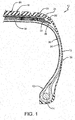
- FIG. 1 An exemplary embodiment of an article of the present invention is shown in Figure 1 .
- the tire 10 includes a bead area 12 and a bead core 14 embedded in the bead area.
- a sidewall 16 extends radially outward from the bead area 12 to a ground-contacting tread 18.
- the tire 10 is reinforced by a carcass 20 that toroidally extends from one bead area 12 to a second bead area (not shown), as known to those skilled in the art.
- the carcass 20 includes at least one ply that preferably winds around each bead core 14.
- a belt reinforcement package 22 is disposed between the carcass 20 and the tread 18.
- the belt reinforcement package 22 may employ specific configurations as desired.
- the belt reinforcement package 22 may include at least one of a radially outer belt structure 24 and a radially inner belt structure 26, and an intermediate belt structure 28 disposed between the radially outer belt structure and the radially inner belt structure.
- an integrated circuit/sensor/antenna unit (not shown), which is typically 5 to 10 mm thick by 20 to 25 mm in diameter, would be attached to an innerliner 30, which is the layer that forms the radial inside of the tire 10.
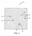
- the tread 18 of the tire 10 includes a material that in turn includes an elastomer compound 32 which may be reinforced with a predetermined amount of rigid particulate inclusions 34, such as carbon black and/or silica.
- the inclusions 34 are dispersed throughout the compound 32 and typically include a size of up to 500 microns or 0.5 millimeters (mm) in diameter.
- the compound 32 may include a limited amount of other particulate inclusions (not shown), such as particles of dirt or sand. Those particulate inclusions may be up to 2,000 microns or 2 mm in diameter. While the size of such dirt or sand particulate inclusions may be larger than the particulate inclusions 34 of carbon black or silica, the amount of such inclusions is limited and the tire 10 is designed to account for a certain amount of them.
- the design of the tire 10 allows for a predetermined number or amount of inclusions 34 in the tread compound 32 that are up to 0.5mm in diameter, and for a limited number of inclusions that are up to 2 mm in diameter.
- the compound 32 of the tread 18 is shown and described by way of example, as the invention applies to any material or compound of a component or structure of the tire 10, including components of the sidewall 16, the carcass 20, the belt reinforcement package 22, and the innerliner 30, as well as other articles that experience repeated deformation.
- the tire 10 includes an electronic component 36 that is incorporated into the material of the tire, such as compound 32, as an inclusion.
- inclusion means a component that is integrated into a compound of a component of the tire 10 as a rigid particulate that is under 2 mm in diameter.
- the electronic component 36 is as small as possible, and may be up to 0.2 mm in diameter or up to 0.5 mm in diameter, as forming techniques (to be described below) dictate.
- the maximum size of the rigid electronic component or components 36 in such a size preferably is no larger than inclusions already existing in the compound, and therefore will not reduce the resistance of the tire 10 to mechanical fatigue during repeated mechanical deformations.
- the size range may be different than that described above, with the understanding that the present invention is directed to a size of the electronic inclusion 36 being no greater than the largest inclusions or grain sizes that are usually present in the material of the articles.
- the term "diameter" as used herein is by way of convenience, as the electronic inclusion may be of any geometric shape known to those skilled in the art, including any circle, sphere, polygon, polyhedron, and the like.
- the electronic component 36 preferably is formed by micro-assembly techniques, such as three-dimensional (3D) printing.
- micro-3D printing techniques have been developed that reduce the size of integrated circuits and other electronic components to a range of under 2 mm in diameter. Such techniques are described in greater detail in WO-A-2016/144944 , WO-A-2016/145309 and US-A-2016/0290880 .
- the electronic component 36 may be inserted into the compound 32 before curing of the tire 10 at a specific location in the tire, as will be described in greater detail below. Once the tire 10 is cured, the electronic component 36 is permanently disposed at its selected location inside the tire. Alternatively, the electronic component 36 may be inserted into the compound 32 after the tire 10 is cured and glued or secured in place by an adhesive or an interference fit. Moreover, the electronic component 36 may be employed in a new tire 10, or in a tire that is being retreaded. For a retreaded tire, the electronic component 36 is inserted into the compound 32 of the new tread, which may be in a flat, circular or semi-circular configuration. The new tread is bonded to the carcass to form the retreaded tire, which includes the electronic component 36.
- the electronic component 36 includes an integrated circuit 38 that processes and stores information.
- the electronic component 36 also includes at least one sensor 40 that is electronically connected to the integrated circuit 38 or is integrated into the integrated circuit. Of course, multiple sensors 40 may be electronically connected to the integrated circuit 38 or integrated into the integrated circuit.
- the electronic component 36 preferably includes an antenna 42 for receiving and transmitting a signal to an external reader, which will be described in greater detail below.
- the antenna 42 is also electronically connected to the integrated circuit 38 and may be carried on a substrate with the integrated circuit.
- the electronic component 36 includes an integrated circuit 38, at least one sensor 40 and an antenna 42 that are integrated with one another or otherwise electronically connected.
- the electronic component 36 may include a modular construction to enable easy electronic connection of multiple sensors 40 or other components.
- the electronic component 36 may include more than one integrated circuit 38. Because the tire 10 is designed to accommodate multiple particulate inclusions, multiple electronic components 36 may be incorporated into several locations in the tire. For example, a plurality of electronic components 36 may be incorporated into the tread compound 32 across the tread 18 and/or about the circumference of the tire 10.
- multiple electronic components 36 may be placed in desired locations as inclusions within the same tire 10 to create an array.
- multiple electronic components 36 may be positioned circumferentially around the tire 10 at locations where stresses and heat are concentrated, such as both edges of a belt or both endings of a ply.
- the use of multiple electronic components 36 as an array of sensors is advantageous for structural health monitoring of the tire 10 because the temperature and stress typically are not uniform around the circumference of the belt edge or ply ending due to inevitable variations in thicknesses caused by splices and the like. Therefore, the health and/or conditions of the tire 10 typically are not uniform around the tire circumference, making it difficult to determine the location of the most adverse conditions in the tire.
- An array provided by multiple electronic components 36 would desirably be able to detect the point of the most adverse conditions in the tire 10. Data from each electronic component 36 in the array preferably is communicated wirelessly, as will be described in greater detail below.
- the electronic component 36 provides a desired electronic function through the use of the sensor 40 and the integrated circuit 38, such as measuring temperature, pressure, wear, force, strain and/or acceleration of the tire 10.
- the sensor 40 may include one or more of at least one sensor includes at least one of a temperature sensor, a pressure sensor, a wear sensor, a force sensor, a strain sensor and an acceleration sensor or accelerometer.
- the electronic component 36 may be configured to receive a radio frequency (RF) power signal and/or transmit an RF data signal using the antenna 42 and the integrated circuit 38.
- the RF signal is an ultra high frequency (UHF) signal in a range of from 300 MegaHertz (MHz) to 3 GigaHertz (GHz).
- the integrated circuit 38 of the electronic component 36 may include a module 44 for storing information that identifies the tire 10 through tire type, manufacturing location and the like, and/or a unique identification code, such as a tire identification (ID) code as will be described in greater detail below.
- the electronic component 36 optionally includes a non-rechargeable battery, rechargeable battery, supercapacitor, energy harvesting structure or wireless power receiver 50 that is integrated with or coupled to the integrated circuit 38, as will be described in greater detail below.
- the electronic component 36 may optionally be encapsulated in a rubber compound 52 that is softer than the tire tread compound 32.
- the encapsulation compound 52 may be a relatively soft gum rubber.
- the electronic component 36 with encapsulation 52 may be inserted into the compound 32 of an uncured tire, which is then cured.
- a pocket may be formed in the cured compound 32, and the electronic component 36 with encapsulation 52 inserted into the pocket.
- the encapsulation compound 52 protects the electronic elements in the component 36 from the mechanical forces arising in the tire 10 during operation by transmitting less force than a denser or harder compound, such as the tread compound 32.
- the encapsulation compound 52 preferably is of a type that allows RF signals and/or wireless power signals as described above to pass through it, which enables efficient signal and/or energy transmission to and from the electronic component 36.
- the electronic component 36 may be disposed at a particular location inside the tire 10 to detect specific information.
- the electronic component 36 may be employed to detect the temperature profiles within the tire 10 during curing.
- the electronic component 36 may be disposed in the last part of the tire 10 to cure, which is referred to as the point of least cure.
- the electronic component 36 measures the actual integrated time and temperature history during the curing of the tire, which may be used to control the cycle time of the curing press.
- Such a measurement of actual temperature at the point of least cure of the tire 10 by the electronic component 36 is more reliable than prediction techniques.
- prediction techniques often add more curing time as a precautionary factor, measurement of actual temperature may reduce the curing time that is required for the tire 10, thereby increasing the efficiency of the curing process.
- the electronic component 36 may also be employed to detect temperature within the tire 10 during its use on a vehicle.
- the electronic component 36 may be disposed at the edge of the intermediate belts 28 in the belt reinforcement package 22 to measure the belt edge temperature.
- Belt edge temperature is an indicator of performance and/or life issues for the tire 10, and by detecting temperature in the compound at the belt edge, the electronic component 36 provides data indicating when tire replacement is recommended.
- the electronic component 36 may also track a temperature versus time history at a specific location, such as the belt edge or a belt splice, in order to provide data to predict when tire replacement should occur.
- the electronic component 36 may be disposed in a lower area of the tire sidewall 16, at the bead area 12 and/or near the bead core 14 for temperature monitoring at a flange of a rim to which the tire 10 is mounted.
- the electronic component 36 may be employed to detect wear of the tire 10 during its use on a vehicle.
- the electronic component 36 may be disposed in the compound 32 of the tread 18 at a specific distance from the radially outer surface of the tread. By measuring changes in electrical resistance, temperature and/or pressure, the electronic component 36 provides data indicating the amount of wear of the tread 18 of the tire 10. Such data may be used to indicate when replacement of the tire 10 is recommended.
- the electronic component 36 may include a strain and force indicator for the tire 10 during its use on a vehicle.
- the electronic component 36 may be disposed in the compound 32 of the tread 18 and/or in the compound of the sidewall 16.
- the electronic component 36 may provide data indicating road conditions, and by measuring the strain in the sidewall 16 of the tire, the electronic component may provide data indicating the load on the tire. This data can be communicated to the vehicle stability and/or braking systems to provide improved control of the vehicle and can also be used for monitoring or tracking driving behavior.
- the integrated circuit 38 of the electronic component 36 may include identification (ID) information for the tire 10.
- the tire ID information may include manufacturing information for the tire 10, such as: the tire type; tire model; size information, such as rim size, width, and outer diameter; manufacturing location; manufacturing date; a treadcap code that includes or correlates to a compound identification; and a mold code that includes or correlates to a tread structure identification.
- the tire ID information may also include a service history or other information to identify specific features and parameters of each tire 10, as well as mechanical characteristics of the tire, such as cornering parameters, spring rate, load-inflation relationship, and the like.
- Such tire identification enables correlation of any of the above data with the specific tire 10 to provide local or central tracking of the tire, its current condition, and/or its condition over time.
- GPS Global positioning system
- GPS Global positioning system
- the electronic component 36 preferably is a passive RF component that is actuated by an external reader 46. More particularly, the electronic component 36, including the integrated circuit 38 and the sensor 40, remain in a passive state.
- the antenna 42 receives a wireless signal from the reader through a reader antenna 48 that actuates the integrated circuit 38.
- the sensor 40 takes its respective measurements, and data from the sensor measurements is communicated to the integrated circuit 38. The data is stored on the integrated circuit 38 and transmitted wirelessly by the antenna 42 from the electronic component 36 to the reader antenna 48 and the reader 46.
- the electronic component After the reader 46 is removed from proximity with the electronic component 36, the electronic component preferably returns to its passive state. Each time that the reader 46 is placed into proximity with the electronic component 36, the electronic component is actuated as described above. In this manner, multiple sensor measurements may be taken and stored without an ongoing power requirement by the electronic component 36.
- the electronic component 36 may include a micro-battery or an energy harvester 50 to extend the transmission range of the electronic component and/or to periodically actuate the electronic component to contact the reader 46.
- the reader 46 may be a hand-held unit or a unit that is attached to a structure in proximity with the electronic component 36.
- the reader 46 may be attached to the vehicle, including the vehicle body or a hub of a rim to which the tire is mounted.
- the reader may be attached on or in a center mechanism of a tire curing press.
- the reader may transmit it to the vehicle control system and/or to a device for analysis of the data.
- the reader 46 may transmit the data to a central server for analysis, or to the cell phone of a user or technician for review.
- an article 10 such as a tire includes the electronic component 36 as a rigid electronic inclusion that is no larger than the largest particulate inclusions already present in typical tire rubber compounds.
- the electronic component 36 provides useful data about the tire while not adversely affecting the performance of the tire, including resistance of the compound to fatigue.
- the present invention also includes a method of forming an article 10 with an electronic component 36 as an inclusion.
- the method includes steps in accordance with the description that is presented above and shown in Figures 1 through 4 .
- tire 10 by way of example, with the understanding that the invention applies to any article that experiences repeated deformation.
- the invention applies to any type of tires, including pneumatic tires, non-pneumatic tires, automotive tires, passenger tires, truck tires, commercial tires, off-the-road tires, aircraft tires, spacecraft tires, and the like, as well as to buildings, bridges, shoe soles, medical devices, rubber engineered products such as air springs and vibration mounts, bearings, sealants, adhesives, and the like.
- the structure of the above-described tire 10 and/or the electronic component 36 may be altered or rearranged, or components or steps known to those skilled in the art omitted or added, without affecting the overall concept or operation of the invention.
- the electronic component 36 may be disposed in any location in the tire 10 as an inclusion, any number of electronic components may be disposed in the tire 10 as inclusions, and other electronic structures may be connected to or integrated into the electronic component.
Landscapes
- Engineering & Computer Science (AREA)
- Mechanical Engineering (AREA)
- Microelectronics & Electronic Packaging (AREA)
- Physics & Mathematics (AREA)
- General Physics & Mathematics (AREA)
- Tires In General (AREA)
Abstract
Description
- The invention relates to articles that experience repeated deformation, such as tires. More particularly, the invention relates to electronic components that sense various conditions within an article that experiences deformation. Specifically, the invention is directed to an article that includes an electronic component that is incorporated into the material of a structure of the article as an inclusion and a respective method of manufacturing.
- Many articles, such as tires, experience repeated deformation. For example, articles that experience repeated deformation include any type of tires, such as pneumatic tires, non-pneumatic tires, automotive tires, passenger tires, truck tires, commercial tires, off-the-road tires, aircraft tires, spacecraft tires, and the like, as well as buildings, bridges, shoe soles, medical devices, rubber engineered products such as air springs and vibration mounts, bearings, sealants, adhesives, and the like. Reference herein is made to a pneumatic tire by way of example, with the understanding that the invention applies to any article that experiences repeated deformation.
- In the manufacture of a pneumatic tire, the tire is typically built on the drum of a tire-building machine, which is known in the art as a tire building drum. Numerous tire components are wrapped about and/or applied to the drum in sequence, forming a cylindrical-shaped tire carcass. The tire carcass is then expanded into a toroidal shape for receipt of the remaining components of the tire, such as a belt package and a rubber tread. The completed toroidally-shaped unvulcanized tire carcass, which is known in the art at that stage as a green tire, is then inserted into a mold or press for forming of the tread pattern and curing or vulcanization.
- Each of the tire components is made of a material that includes an elastomer compound, and certain components may be reinforced with other materials depending on specific design and performance requirements. For example, the belt package includes layers of strips of rubber that are reinforced with cords, and the tread is typically an elastomer compound that may be reinforced with particulate materials.
- For many modern tires, it is often desirable to mount electronic components to the tires either before or after curing. Such electronic components enable the temperature, pressure and/or other parameters of the tire to be continuously monitored during vehicle operation. All modern electronic components include an integrated circuit that processes and stores information. One or more sensors are integrated with or electronically connected to the integrated circuit. An antenna for receiving and transmitting a signal to an external reader is also electronically connected to the integrated circuit, and may be carried on a substrate with the integrated circuit.
- In the prior art, such electronic components have typically been attached to the inside surface of a pneumatic tire, which defines the cavity containing the inflation gas. Such a location has enabled the electronic components to continuously sense parameters such as the temperature and pressure inside the tire cavity, while not interfering with the structure of the tire. More particularly, prior art electronic component units for tires have typically been 5 to 10 millimeters (mm) thick by 20 to 25 mm in diameter. Because the integrity of the tire components is important, the size of prior art electronic component units has dictated placement on the inside surface of the pneumatic tire, and thus inside the tire cavity.
- While prior art electronic component units are acceptable for many uses, it is desirable to monitor the actual temperature and other parameters at specific structural locations inside the tire structure during use on a vehicle or on a dynamic tire testing apparatus. For example, monitoring the actual temperature at the edge of the belts in the belt package would be advantageous in predicting ongoing tire performance and potential tire replacement, as well as in providing immediate information to a driver or dispatcher to adjust the speed of a vehicle before potential thermal damage to the tire may occur. However, accurate measurement of the actual temperature at such a location requires the electronic component unit to be permanently embedded into the tire interior structure. Due to the size of prior art electronic component units, any permanent embedding of such units into the tire interior structure may undesirably impair the structure of the tire by potentially creating stress risers, which may compromise the fatigue resistance of the tire.
- Other prior art techniques of measuring the interior temperature of tires at specific locations has included inserting needle-like temperature-measuring probes into the structure of the tire until the tip of the probe reaches the desired location. Such prior art techniques are not suitable for monitoring temperature during tire use, since the tire has to be stationary while the needle is inserted and removed.
- As a result, it is desirable to develop an article, such as a tire, which includes an electronic component that is integrated into the structure of the article without adversely affecting the performance or life of the article.
- The invention relates to an article in accordance with claim 1 and to a method in accordance with
claim 14. - Dependent claims refer to preferred embodiments of the invention.
- According to an aspect of an exemplary embodiment of the invention, an article with an electronic component inclusion is provided. The article includes at least one structural element, in which the structural element includes a material. At least one electronic component is incorporated into the material as an inclusion, and the electronic component includes an integrated circuit.
-
- "Axial" and "axially" mean lines or directions that are parallel to the axis of rotation of the tire.
- "Axially inward" and "axially inwardly" refer to an axial direction that is toward the axial center of the tire.
- "Axially outward" and "axially outwardly" refer to an axial direction that is away from the axial center of the tire.
- "Circumferential" means lines or directions extending along the perimeter of the surface of the annular tread perpendicular to the axial direction.
- "Innerliner" means the layer or layers of elastomer or other material that form the inside surface of a tubeless tire and that contain the inflating fluid within the tire.
- "Radial" and "radially" mean lines or directions that are perpendicular to the axis of rotation of the tire.
- The invention will be described by way of example and with reference to the accompanying drawings, in which:
-
Figure 1 is a schematic cross-sectional view of an exemplary article of the present invention; -
Figure 2 is a representation of the microstructure of a vulcanized rubber compound of a structural component of the article shown inFigure 1 ; -
Figure 3 is a circuit diagram of an exemplary electronic component incorporated into a compound of the article shown inFigure 1 ; and -
Figure 4 is a schematic representation of a reader and the exemplary electronic component shown inFigure 3 . - Similar numerals refer to similar parts throughout the drawings.
- An exemplary embodiment of an article of the present invention is shown in
Figure 1 . By way of example, the article is shown and described herein as atire 10, with the understanding that the invention applies to any article that experiences repeated deformation. Thetire 10 includes abead area 12 and abead core 14 embedded in the bead area. Asidewall 16 extends radially outward from thebead area 12 to a ground-contactingtread 18. Thetire 10 is reinforced by acarcass 20 that toroidally extends from onebead area 12 to a second bead area (not shown), as known to those skilled in the art. Thecarcass 20 includes at least one ply that preferably winds around eachbead core 14. - A
belt reinforcement package 22 is disposed between thecarcass 20 and thetread 18. Thebelt reinforcement package 22 may employ specific configurations as desired. For example, thebelt reinforcement package 22 may include at least one of a radiallyouter belt structure 24 and a radiallyinner belt structure 26, and anintermediate belt structure 28 disposed between the radially outer belt structure and the radially inner belt structure. In the prior art, an integrated circuit/sensor/antenna unit (not shown), which is typically 5 to 10 mm thick by 20 to 25 mm in diameter, would be attached to aninnerliner 30, which is the layer that forms the radial inside of thetire 10. - With additional reference to
Figure 2 , thetread 18 of thetire 10 includes a material that in turn includes anelastomer compound 32 which may be reinforced with a predetermined amount ofrigid particulate inclusions 34, such as carbon black and/or silica. Theinclusions 34 are dispersed throughout thecompound 32 and typically include a size of up to 500 microns or 0.5 millimeters (mm) in diameter. - In addition, the
compound 32 may include a limited amount of other particulate inclusions (not shown), such as particles of dirt or sand. Those particulate inclusions may be up to 2,000 microns or 2 mm in diameter. While the size of such dirt or sand particulate inclusions may be larger than theparticulate inclusions 34 of carbon black or silica, the amount of such inclusions is limited and thetire 10 is designed to account for a certain amount of them. - Therefore, the design of the
tire 10 allows for a predetermined number or amount ofinclusions 34 in thetread compound 32 that are up to 0.5mm in diameter, and for a limited number of inclusions that are up to 2 mm in diameter. It is to be understood that thecompound 32 of thetread 18 is shown and described by way of example, as the invention applies to any material or compound of a component or structure of thetire 10, including components of thesidewall 16, thecarcass 20, thebelt reinforcement package 22, and theinnerliner 30, as well as other articles that experience repeated deformation. - In accordance with a feature of the invention, the
tire 10 includes anelectronic component 36 that is incorporated into the material of the tire, such ascompound 32, as an inclusion. It is to be understood that the term inclusion as used herein means a component that is integrated into a compound of a component of thetire 10 as a rigid particulate that is under 2 mm in diameter. For example, theelectronic component 36 is as small as possible, and may be up to 0.2 mm in diameter or up to 0.5 mm in diameter, as forming techniques (to be described below) dictate. The maximum size of the rigid electronic component orcomponents 36 in such a size preferably is no larger than inclusions already existing in the compound, and therefore will not reduce the resistance of thetire 10 to mechanical fatigue during repeated mechanical deformations. - In non-rubber articles that experience deformation, the size range may be different than that described above, with the understanding that the present invention is directed to a size of the
electronic inclusion 36 being no greater than the largest inclusions or grain sizes that are usually present in the material of the articles. It is to be understood that the term "diameter" as used herein is by way of convenience, as the electronic inclusion may be of any geometric shape known to those skilled in the art, including any circle, sphere, polygon, polyhedron, and the like. - The
electronic component 36 preferably is formed by micro-assembly techniques, such as three-dimensional (3D) printing. For example, micro-3D printing techniques have been developed that reduce the size of integrated circuits and other electronic components to a range of under 2 mm in diameter. Such techniques are described in greater detail inWO-A-2016/144944 ,WO-A-2016/145309 andUS-A-2016/0290880 . - The
electronic component 36 may be inserted into thecompound 32 before curing of thetire 10 at a specific location in the tire, as will be described in greater detail below. Once thetire 10 is cured, theelectronic component 36 is permanently disposed at its selected location inside the tire. Alternatively, theelectronic component 36 may be inserted into thecompound 32 after thetire 10 is cured and glued or secured in place by an adhesive or an interference fit. Moreover, theelectronic component 36 may be employed in anew tire 10, or in a tire that is being retreaded. For a retreaded tire, theelectronic component 36 is inserted into thecompound 32 of the new tread, which may be in a flat, circular or semi-circular configuration. The new tread is bonded to the carcass to form the retreaded tire, which includes theelectronic component 36. - With reference to
Figure 3 , theelectronic component 36 includes anintegrated circuit 38 that processes and stores information. Theelectronic component 36 also includes at least onesensor 40 that is electronically connected to theintegrated circuit 38 or is integrated into the integrated circuit. Of course,multiple sensors 40 may be electronically connected to theintegrated circuit 38 or integrated into the integrated circuit. Theelectronic component 36 preferably includes anantenna 42 for receiving and transmitting a signal to an external reader, which will be described in greater detail below. Theantenna 42 is also electronically connected to theintegrated circuit 38 and may be carried on a substrate with the integrated circuit. - In this manner, the
electronic component 36 includes anintegrated circuit 38, at least onesensor 40 and anantenna 42 that are integrated with one another or otherwise electronically connected. Theelectronic component 36 may include a modular construction to enable easy electronic connection ofmultiple sensors 40 or other components. In addition, theelectronic component 36 may include more than one integratedcircuit 38. Because thetire 10 is designed to accommodate multiple particulate inclusions, multipleelectronic components 36 may be incorporated into several locations in the tire. For example, a plurality ofelectronic components 36 may be incorporated into thetread compound 32 across thetread 18 and/or about the circumference of thetire 10. - As shown in
Figure 1 , multipleelectronic components 36 may be placed in desired locations as inclusions within thesame tire 10 to create an array. For example, multipleelectronic components 36 may be positioned circumferentially around thetire 10 at locations where stresses and heat are concentrated, such as both edges of a belt or both endings of a ply. The use of multipleelectronic components 36 as an array of sensors is advantageous for structural health monitoring of thetire 10 because the temperature and stress typically are not uniform around the circumference of the belt edge or ply ending due to inevitable variations in thicknesses caused by splices and the like. Therefore, the health and/or conditions of thetire 10 typically are not uniform around the tire circumference, making it difficult to determine the location of the most adverse conditions in the tire. An array provided by multipleelectronic components 36 would desirably be able to detect the point of the most adverse conditions in thetire 10. Data from eachelectronic component 36 in the array preferably is communicated wirelessly, as will be described in greater detail below. - The
electronic component 36 provides a desired electronic function through the use of thesensor 40 and theintegrated circuit 38, such as measuring temperature, pressure, wear, force, strain and/or acceleration of thetire 10. For example, thesensor 40 may include one or more of at least one sensor includes at least one of a temperature sensor, a pressure sensor, a wear sensor, a force sensor, a strain sensor and an acceleration sensor or accelerometer. - In addition, as shown in
Figure 3 , theelectronic component 36 may be configured to receive a radio frequency (RF) power signal and/or transmit an RF data signal using theantenna 42 and theintegrated circuit 38. Preferably, the RF signal is an ultra high frequency (UHF) signal in a range of from 300 MegaHertz (MHz) to 3 GigaHertz (GHz). Moreover, theintegrated circuit 38 of theelectronic component 36 may include amodule 44 for storing information that identifies thetire 10 through tire type, manufacturing location and the like, and/or a unique identification code, such as a tire identification (ID) code as will be described in greater detail below. Theelectronic component 36 optionally includes a non-rechargeable battery, rechargeable battery, supercapacitor, energy harvesting structure orwireless power receiver 50 that is integrated with or coupled to theintegrated circuit 38, as will be described in greater detail below. - Returning to
Figure 2 , theelectronic component 36 may optionally be encapsulated in arubber compound 52 that is softer than thetire tread compound 32. For example, theencapsulation compound 52 may be a relatively soft gum rubber. Theelectronic component 36 withencapsulation 52 may be inserted into thecompound 32 of an uncured tire, which is then cured. Alternatively, for atire 10 that has already been cured, a pocket may be formed in the curedcompound 32, and theelectronic component 36 withencapsulation 52 inserted into the pocket. Theencapsulation compound 52 protects the electronic elements in thecomponent 36 from the mechanical forces arising in thetire 10 during operation by transmitting less force than a denser or harder compound, such as thetread compound 32. In addition, theencapsulation compound 52 preferably is of a type that allows RF signals and/or wireless power signals as described above to pass through it, which enables efficient signal and/or energy transmission to and from theelectronic component 36. - As shown in
Figure 1 and mentioned above, theelectronic component 36 may be disposed at a particular location inside thetire 10 to detect specific information. For example, theelectronic component 36 may be employed to detect the temperature profiles within thetire 10 during curing. In such a case, theelectronic component 36 may be disposed in the last part of thetire 10 to cure, which is referred to as the point of least cure. By being located at the point of least cure in thetire 10, theelectronic component 36 measures the actual integrated time and temperature history during the curing of the tire, which may be used to control the cycle time of the curing press. Such a measurement of actual temperature at the point of least cure of thetire 10 by theelectronic component 36 is more reliable than prediction techniques. In addition, because prediction techniques often add more curing time as a precautionary factor, measurement of actual temperature may reduce the curing time that is required for thetire 10, thereby increasing the efficiency of the curing process. - The
electronic component 36 may also be employed to detect temperature within thetire 10 during its use on a vehicle. For example, theelectronic component 36 may be disposed at the edge of theintermediate belts 28 in thebelt reinforcement package 22 to measure the belt edge temperature. Belt edge temperature is an indicator of performance and/or life issues for thetire 10, and by detecting temperature in the compound at the belt edge, theelectronic component 36 provides data indicating when tire replacement is recommended. Theelectronic component 36 may also track a temperature versus time history at a specific location, such as the belt edge or a belt splice, in order to provide data to predict when tire replacement should occur. Moreover, theelectronic component 36 may be disposed in a lower area of thetire sidewall 16, at thebead area 12 and/or near thebead core 14 for temperature monitoring at a flange of a rim to which thetire 10 is mounted. - In addition, the
electronic component 36 may be employed to detect wear of thetire 10 during its use on a vehicle. For example, theelectronic component 36 may be disposed in thecompound 32 of thetread 18 at a specific distance from the radially outer surface of the tread. By measuring changes in electrical resistance, temperature and/or pressure, theelectronic component 36 provides data indicating the amount of wear of thetread 18 of thetire 10. Such data may be used to indicate when replacement of thetire 10 is recommended. - Moreover, the
electronic component 36 may include a strain and force indicator for thetire 10 during its use on a vehicle. For example, theelectronic component 36 may be disposed in thecompound 32 of thetread 18 and/or in the compound of thesidewall 16. By measuring the strain in thetread 18 of thetire 10, theelectronic component 36 may provide data indicating road conditions, and by measuring the strain in thesidewall 16 of the tire, the electronic component may provide data indicating the load on the tire. This data can be communicated to the vehicle stability and/or braking systems to provide improved control of the vehicle and can also be used for monitoring or tracking driving behavior. - As mentioned above, the
integrated circuit 38 of theelectronic component 36 may include identification (ID) information for thetire 10. The tire ID information may include manufacturing information for thetire 10, such as: the tire type; tire model; size information, such as rim size, width, and outer diameter; manufacturing location; manufacturing date; a treadcap code that includes or correlates to a compound identification; and a mold code that includes or correlates to a tread structure identification. The tire ID information may also include a service history or other information to identify specific features and parameters of eachtire 10, as well as mechanical characteristics of the tire, such as cornering parameters, spring rate, load-inflation relationship, and the like. Such tire identification enables correlation of any of the above data with thespecific tire 10 to provide local or central tracking of the tire, its current condition, and/or its condition over time. For example, Global positioning system (GPS) capability may be included to provide location tracking of thetire 10 during transport and/or location tracking of the vehicle on which the tire is installed. - Referring now to
Figures 3 and 4 , theelectronic component 36 preferably is a passive RF component that is actuated by anexternal reader 46. More particularly, theelectronic component 36, including the integratedcircuit 38 and thesensor 40, remain in a passive state. When thereader 46 and is placed in proximity with theelectronic component 36, theantenna 42 receives a wireless signal from the reader through areader antenna 48 that actuates theintegrated circuit 38. Thesensor 40 takes its respective measurements, and data from the sensor measurements is communicated to theintegrated circuit 38. The data is stored on theintegrated circuit 38 and transmitted wirelessly by theantenna 42 from theelectronic component 36 to thereader antenna 48 and thereader 46. - After the
reader 46 is removed from proximity with theelectronic component 36, the electronic component preferably returns to its passive state. Each time that thereader 46 is placed into proximity with theelectronic component 36, the electronic component is actuated as described above. In this manner, multiple sensor measurements may be taken and stored without an ongoing power requirement by theelectronic component 36. Optionally, theelectronic component 36 may include a micro-battery or anenergy harvester 50 to extend the transmission range of the electronic component and/or to periodically actuate the electronic component to contact thereader 46. - The
reader 46 may be a hand-held unit or a unit that is attached to a structure in proximity with theelectronic component 36. For example, when theelectronic component 36 is used to detect parameters of thetire 10 during operation of a vehicle, thereader 46 may be attached to the vehicle, including the vehicle body or a hub of a rim to which the tire is mounted. When theelectronic component 36 is used to detect parameters of thetire 10 during curing, the reader may be attached on or in a center mechanism of a tire curing press. Once the data is received by thereader 46, the reader may transmit it to the vehicle control system and/or to a device for analysis of the data. For example, thereader 46 may transmit the data to a central server for analysis, or to the cell phone of a user or technician for review. - In this manner, an
article 10 such as a tire includes theelectronic component 36 as a rigid electronic inclusion that is no larger than the largest particulate inclusions already present in typical tire rubber compounds. By being incorporated as an inclusion into a compound of a structure of thetire 10 at such a size, theelectronic component 36 provides useful data about the tire while not adversely affecting the performance of the tire, including resistance of the compound to fatigue. - The present invention also includes a method of forming an
article 10 with anelectronic component 36 as an inclusion. The method includes steps in accordance with the description that is presented above and shown inFigures 1 through 4 . - Reference herein has been made to a
tire 10 by way of example, with the understanding that the invention applies to any article that experiences repeated deformation. For example, the invention applies to any type of tires, including pneumatic tires, non-pneumatic tires, automotive tires, passenger tires, truck tires, commercial tires, off-the-road tires, aircraft tires, spacecraft tires, and the like, as well as to buildings, bridges, shoe soles, medical devices, rubber engineered products such as air springs and vibration mounts, bearings, sealants, adhesives, and the like. - It is also to be understood that the structure of the above-described
tire 10 and/or theelectronic component 36 may be altered or rearranged, or components or steps known to those skilled in the art omitted or added, without affecting the overall concept or operation of the invention. For example, theelectronic component 36 may be disposed in any location in thetire 10 as an inclusion, any number of electronic components may be disposed in thetire 10 as inclusions, and other electronic structures may be connected to or integrated into the electronic component.
Claims (15)
- An article with an electronic component inclusion, the article (10) comprising at least one structural element, the structural element including a material (32) and at least one electronic component (36) being incorporated into the material (32) as an inclusion, the electronic component (36) including an integrated circuit (38).
- The article of claim 1, wherein the electronic component (36) has a diameter of up to 2 millimeters or up to 0.5 millimeters,
- The article of claim 1 or 2, wherein the electronic component (36) includes at least one sensor (40) in electronic communication with the integrated circuit (38); and/or wherein the at least one sensor (40) includes at least one of a temperature sensor, a pressure sensor, a wear sensor, a force sensor, a strain sensor and an acceleration sensor.
- The article of at least one of the previous claims, wherein the electronic component (36) includes a modular construction with multiple sensors; and/or wherein the at least one electronic component (36) includes multiple electronic components that are electrically interconnected.
- The article of at least one of the previous claims, wherein the electronic component (36) includes an antenna (42) in electronic communication with the integrated circuit (38).
- The article of at least one of the previous claims, wherein the article (10) includes a plurality of materials (32, 36, 52) and wherein the at least one electronic component (36) is incorporated into a respective one of the materials (32, 36, 52) as an inclusion.
- The article of at least one of the previous claims, wherein the electronic component (36) includes at least one of a battery, a supercapacitor, an energy harvesting structure (50) and a wireless power receiver.
- The article of at least one of the previous claims, wherein the electronic component (36) is a passive radio frequency unit that is actuated by an external reader (46).
- The article of at least one of the previous claims, wherein the material (32) is a first material and the electronic component (36) is encapsulated in a second material (52) that is softer than the first material.
- The article of at least one of the previous claims, wherein the article is a tire (10), and, preferably, wherein the integrated circuit (38) includes information for identification of the tire (10).
- The article of claim 10, wherein the tire (10) comprises:a pair of bead areas (12);a sidewall (16) extending from each respective bead area (12) to a tread (18), the sidewall (16) including a first compound and the tread (18) including a second compound;a carcass (20) extending toroidally between each of the bead areas (12), the carcass (20) including a third compound; anda belt reinforcement package (22) disposed between the tread (12) and the carcass (20), the belt reinforcing package (22) including a fourth compound; andwherein the at least one electronic component (36) is incorporated into at least one of the first, second, third or fourth compound as an inclusion.
- The article of claim 11, wherein the at least one of the first, second, third or fourth compound includes a plurality of electronic components (36) incorporated into the at least one of the first, second, third or fourth compound as inclusions.
- The article of claim 11, wherein the at least one electronic component (36) includes a plurality of electronic components incorporated into at least one of the first, second, third or fourth compound as a respective plurality of inclusions.
- A method of manufacturing an article with an electronic component inclusion in accordance with at least one of the previous claims, the method comprising inserting the electronic component (36) into at least one of the first, second, third or fourth compounds before, after or while curing of the tire (10), and, optionally, wherein the electronic component (36) is disposed at a point of least cure in the tire (10) or close to point of least cure in the tire (10).
- A method of manufacturing an article with an electronic component inclusion in accordance with at least one of the previous claims 1 to 13, wherein the electronic component (36) is formed by a micro-assembly technique.
Applications Claiming Priority (2)
| Application Number | Priority Date | Filing Date | Title |
|---|---|---|---|
| US201762608123P | 2017-12-20 | 2017-12-20 | |
| US16/182,869 US10792960B2 (en) | 2017-12-20 | 2018-11-07 | Article with electronic component inclusion |
Publications (2)
| Publication Number | Publication Date |
|---|---|
| EP3505336A1 true EP3505336A1 (en) | 2019-07-03 |
| EP3505336B1 EP3505336B1 (en) | 2021-09-01 |
Family
ID=64744693
Family Applications (1)
| Application Number | Title | Priority Date | Filing Date |
|---|---|---|---|
| EP18213551.7A Active EP3505336B1 (en) | 2017-12-20 | 2018-12-18 | Article with electronic component inclusion and method of manufacturing |
Country Status (2)
| Country | Link |
|---|---|
| US (1) | US10792960B2 (en) |
| EP (1) | EP3505336B1 (en) |
Cited By (2)
| Publication number | Priority date | Publication date | Assignee | Title |
|---|---|---|---|---|
| EP3663110A1 (en) * | 2018-12-05 | 2020-06-10 | The Goodyear Tire & Rubber Company | Integrated tire sensor and reader system |
| US10935466B2 (en) | 2017-12-20 | 2021-03-02 | The Goodyear Tire & Rubber Company | Integrated tire sensor and reader system |
Families Citing this family (6)
| Publication number | Priority date | Publication date | Assignee | Title |
|---|---|---|---|---|
| US11273801B2 (en) | 2018-12-18 | 2022-03-15 | The Goodyear Tire & Rubber Company | Control system for an air maintenance tire system |
| JP6756004B1 (en) * | 2019-05-08 | 2020-09-16 | Toyo Tire株式会社 | Tires and tire manufacturing methods |
| CN115103779A (en) * | 2020-02-17 | 2022-09-23 | 横滨橡胶株式会社 | RFID module and pneumatic tire in which the RFID module is embedded |
| CN115052759B (en) * | 2020-02-17 | 2024-08-02 | 横滨橡胶株式会社 | Pneumatic tire |
| DE112021000296T5 (en) * | 2020-02-17 | 2022-10-27 | The Yokohama Rubber Co., Ltd. | tire |
| JP2024082100A (en) * | 2022-12-07 | 2024-06-19 | 株式会社ブリヂストン | Tire condition display device, terminal device, and tire condition display method |
Citations (4)
| Publication number | Priority date | Publication date | Assignee | Title |
|---|---|---|---|---|
| EP2275286A1 (en) * | 2006-04-25 | 2011-01-19 | Bridgestone Americas Tire Operations, LLC | Elastomeric article with wireless micro and nano sensor system |
| WO2016144944A1 (en) | 2015-03-09 | 2016-09-15 | President And Fellows Of Harvard College | Method of making an electrode structure and a microbattery cell |
| WO2016145309A1 (en) | 2015-03-11 | 2016-09-15 | President And Fellows Of Harvard College | 3d printed flexible electronic device |
| US20160290880A1 (en) | 2013-11-18 | 2016-10-06 | President And Fellows Of Harvard College | Printed stretchable strain sensor |
Family Cites Families (13)
| Publication number | Priority date | Publication date | Assignee | Title |
|---|---|---|---|---|
| US4695823A (en) | 1984-04-27 | 1987-09-22 | Vernon Roger W | Vehicle tire monitoring apparatus |
| US4911217A (en) | 1989-03-24 | 1990-03-27 | The Goodyear Tire & Rubber Company | Integrated circuit transponder in a pneumatic tire for tire identification |
| US5218861A (en) | 1991-03-27 | 1993-06-15 | The Goodyear Tire & Rubber Company | Pneumatic tire having an integrated circuit transponder and pressure transducer |
| US5181975A (en) | 1991-03-27 | 1993-01-26 | The Goodyear Tire & Rubber Company | Integrated circuit transponder with coil antenna in a pneumatic tire for use in tire identification |
| FR2682323A1 (en) | 1991-10-15 | 1993-04-16 | Michelin & Cie | IMPLEMENTATION OF AN ELECTRONIC CIRCUIT IN A TIRE. |
| US20050076982A1 (en) * | 2003-10-09 | 2005-04-14 | Metcalf Arthur Richard | Post patch assembly for mounting devices in a tire interior |
| US20060185429A1 (en) | 2005-02-21 | 2006-08-24 | Finemems Inc. | An Intelligent Integrated Sensor Of Tire Pressure Monitoring System (TPMS) |
| JP5146309B2 (en) * | 2006-02-27 | 2013-02-20 | 横浜ゴム株式会社 | Rubber-coated RFID module and pneumatic tire embedded therewith |
| DE602007003952D1 (en) | 2007-04-27 | 2010-02-04 | Infineon Technologies Ag | System for measuring tire pressure with reduced power consumption |
| US7741964B2 (en) | 2007-05-31 | 2010-06-22 | Schrader Electronics Ltd. | Tire pressure detector having reduced power consumption mechanism |
| DE102014111968A1 (en) | 2014-08-08 | 2016-02-11 | Huf Hülsbeck & Fürst Gmbh & Co. Kg | Universal tire pressure sensor |
| DE102014111966A1 (en) | 2014-08-08 | 2016-02-11 | Huf Hülsbeck & Fürst Gmbh & Co. Kg | Universal tire pressure sensor |
| US10126153B2 (en) * | 2014-07-22 | 2018-11-13 | Deere & Company | Particulate matter impact sensor |
-
2018
- 2018-11-07 US US16/182,869 patent/US10792960B2/en active Active
- 2018-12-18 EP EP18213551.7A patent/EP3505336B1/en active Active
Patent Citations (4)
| Publication number | Priority date | Publication date | Assignee | Title |
|---|---|---|---|---|
| EP2275286A1 (en) * | 2006-04-25 | 2011-01-19 | Bridgestone Americas Tire Operations, LLC | Elastomeric article with wireless micro and nano sensor system |
| US20160290880A1 (en) | 2013-11-18 | 2016-10-06 | President And Fellows Of Harvard College | Printed stretchable strain sensor |
| WO2016144944A1 (en) | 2015-03-09 | 2016-09-15 | President And Fellows Of Harvard College | Method of making an electrode structure and a microbattery cell |
| WO2016145309A1 (en) | 2015-03-11 | 2016-09-15 | President And Fellows Of Harvard College | 3d printed flexible electronic device |
Cited By (2)
| Publication number | Priority date | Publication date | Assignee | Title |
|---|---|---|---|---|
| US10935466B2 (en) | 2017-12-20 | 2021-03-02 | The Goodyear Tire & Rubber Company | Integrated tire sensor and reader system |
| EP3663110A1 (en) * | 2018-12-05 | 2020-06-10 | The Goodyear Tire & Rubber Company | Integrated tire sensor and reader system |
Also Published As
| Publication number | Publication date |
|---|---|
| EP3505336B1 (en) | 2021-09-01 |
| US20190184771A1 (en) | 2019-06-20 |
| US10792960B2 (en) | 2020-10-06 |
Similar Documents
| Publication | Publication Date | Title |
|---|---|---|
| EP3505336B1 (en) | Article with electronic component inclusion and method of manufacturing | |
| EP3838631B1 (en) | Flexible tire sensor unit and tire | |
| US10935466B2 (en) | Integrated tire sensor and reader system | |
| EP3838632B1 (en) | Encapsulated embedded tire sensor unit | |
| US11675995B2 (en) | Post-cure read range enhancement of RFID tire tags | |
| EP3628513B1 (en) | Tire with printed shear sensors | |
| CN114580592B (en) | RFID tags attached to tires | |
| CN104589928B (en) | Pneumatic tire | |
| EP3628479B1 (en) | Tire with printed strain sensors | |
| US20210016614A1 (en) | Tire with an integrated rfid and tpms sensor | |
| EP4015255B1 (en) | Tire with polymer plug for tread wear sensing and method of manufacturing | |
| CN101432154A (en) | Device for fixing a module to the inner wall of a tyre | |
| US20230161993A1 (en) | Antenna connection for integrated rfid tag and tpms sensor | |
| CN1318231C (en) | System and method for monitoring characteristic parameters of a tyre | |
| EP4015252B1 (en) | Vehicle tire sensor retaining system | |
| EP4197823A1 (en) | Tire with cellular member and sensor | |
| JP2003501733A (en) | System for detecting tire pressure of automobile tires | |
| US20260061784A1 (en) | Systems and methods for integrating sensors into rim flange transition area of a tire during process of manufacture | |
| US11117429B2 (en) | Tire with sensor attachment reservoir and method of attaching sensor | |
| EP4015256A1 (en) | Tire sensor container system | |
| EP3663110B1 (en) | Integrated tire sensor and reader system | |
| US20240416690A1 (en) | Sensor data retrieval from radio frequency identification (rfid) device | |
| CN119142076A (en) | Tyre with a set of print sensors | |
| CN119159931A (en) | Detection of uneven and irregular tread wear |
Legal Events
| Date | Code | Title | Description |
|---|---|---|---|
| PUAI | Public reference made under article 153(3) epc to a published international application that has entered the european phase |
Free format text: ORIGINAL CODE: 0009012 |
|
| STAA | Information on the status of an ep patent application or granted ep patent |
Free format text: STATUS: THE APPLICATION HAS BEEN PUBLISHED |
|
| AK | Designated contracting states |
Kind code of ref document: A1 Designated state(s): AL AT BE BG CH CY CZ DE DK EE ES FI FR GB GR HR HU IE IS IT LI LT LU LV MC MK MT NL NO PL PT RO RS SE SI SK SM TR |
|
| AX | Request for extension of the european patent |
Extension state: BA ME |
|
| STAA | Information on the status of an ep patent application or granted ep patent |
Free format text: STATUS: REQUEST FOR EXAMINATION WAS MADE |
|
| 17P | Request for examination filed |
Effective date: 20200103 |
|
| RBV | Designated contracting states (corrected) |
Designated state(s): AL AT BE BG CH CY CZ DE DK EE ES FI FR GB GR HR HU IE IS IT LI LT LU LV MC MK MT NL NO PL PT RO RS SE SI SK SM TR |
|
| STAA | Information on the status of an ep patent application or granted ep patent |
Free format text: STATUS: EXAMINATION IS IN PROGRESS |
|
| 17Q | First examination report despatched |
Effective date: 20200702 |
|
| GRAP | Despatch of communication of intention to grant a patent |
Free format text: ORIGINAL CODE: EPIDOSNIGR1 |
|
| STAA | Information on the status of an ep patent application or granted ep patent |
Free format text: STATUS: GRANT OF PATENT IS INTENDED |
|
| INTG | Intention to grant announced |
Effective date: 20210406 |
|
| GRAS | Grant fee paid |
Free format text: ORIGINAL CODE: EPIDOSNIGR3 |
|
| GRAA | (expected) grant |
Free format text: ORIGINAL CODE: 0009210 |
|
| STAA | Information on the status of an ep patent application or granted ep patent |
Free format text: STATUS: THE PATENT HAS BEEN GRANTED |
|
| AK | Designated contracting states |
Kind code of ref document: B1 Designated state(s): AL AT BE BG CH CY CZ DE DK EE ES FI FR GB GR HR HU IE IS IT LI LT LU LV MC MK MT NL NO PL PT RO RS SE SI SK SM TR |
|
| REG | Reference to a national code |
Ref country code: GB Ref legal event code: FG4D |
|
| REG | Reference to a national code |
Ref country code: CH Ref legal event code: EP Ref country code: AT Ref legal event code: REF Ref document number: 1425796 Country of ref document: AT Kind code of ref document: T Effective date: 20210915 |
|
| REG | Reference to a national code |
Ref country code: DE Ref legal event code: R096 Ref document number: 602018022754 Country of ref document: DE |
|
| REG | Reference to a national code |
Ref country code: IE Ref legal event code: FG4D |
|
| REG | Reference to a national code |
Ref country code: LT Ref legal event code: MG9D |
|
| REG | Reference to a national code |
Ref country code: NL Ref legal event code: MP Effective date: 20210901 |
|
| PG25 | Lapsed in a contracting state [announced via postgrant information from national office to epo] |
Ref country code: BG Free format text: LAPSE BECAUSE OF FAILURE TO SUBMIT A TRANSLATION OF THE DESCRIPTION OR TO PAY THE FEE WITHIN THE PRESCRIBED TIME-LIMIT Effective date: 20211201 Ref country code: LT Free format text: LAPSE BECAUSE OF FAILURE TO SUBMIT A TRANSLATION OF THE DESCRIPTION OR TO PAY THE FEE WITHIN THE PRESCRIBED TIME-LIMIT Effective date: 20210901 Ref country code: NO Free format text: LAPSE BECAUSE OF FAILURE TO SUBMIT A TRANSLATION OF THE DESCRIPTION OR TO PAY THE FEE WITHIN THE PRESCRIBED TIME-LIMIT Effective date: 20211201 Ref country code: RS Free format text: LAPSE BECAUSE OF FAILURE TO SUBMIT A TRANSLATION OF THE DESCRIPTION OR TO PAY THE FEE WITHIN THE PRESCRIBED TIME-LIMIT Effective date: 20210901 Ref country code: SE Free format text: LAPSE BECAUSE OF FAILURE TO SUBMIT A TRANSLATION OF THE DESCRIPTION OR TO PAY THE FEE WITHIN THE PRESCRIBED TIME-LIMIT Effective date: 20210901 Ref country code: HR Free format text: LAPSE BECAUSE OF FAILURE TO SUBMIT A TRANSLATION OF THE DESCRIPTION OR TO PAY THE FEE WITHIN THE PRESCRIBED TIME-LIMIT Effective date: 20210901 Ref country code: ES Free format text: LAPSE BECAUSE OF FAILURE TO SUBMIT A TRANSLATION OF THE DESCRIPTION OR TO PAY THE FEE WITHIN THE PRESCRIBED TIME-LIMIT Effective date: 20210901 Ref country code: FI Free format text: LAPSE BECAUSE OF FAILURE TO SUBMIT A TRANSLATION OF THE DESCRIPTION OR TO PAY THE FEE WITHIN THE PRESCRIBED TIME-LIMIT Effective date: 20210901 |
|
| REG | Reference to a national code |
Ref country code: AT Ref legal event code: MK05 Ref document number: 1425796 Country of ref document: AT Kind code of ref document: T Effective date: 20210901 |
|
| PG25 | Lapsed in a contracting state [announced via postgrant information from national office to epo] |
Ref country code: PL Free format text: LAPSE BECAUSE OF FAILURE TO SUBMIT A TRANSLATION OF THE DESCRIPTION OR TO PAY THE FEE WITHIN THE PRESCRIBED TIME-LIMIT Effective date: 20210901 Ref country code: LV Free format text: LAPSE BECAUSE OF FAILURE TO SUBMIT A TRANSLATION OF THE DESCRIPTION OR TO PAY THE FEE WITHIN THE PRESCRIBED TIME-LIMIT Effective date: 20210901 Ref country code: GR Free format text: LAPSE BECAUSE OF FAILURE TO SUBMIT A TRANSLATION OF THE DESCRIPTION OR TO PAY THE FEE WITHIN THE PRESCRIBED TIME-LIMIT Effective date: 20211202 |
|
| PG25 | Lapsed in a contracting state [announced via postgrant information from national office to epo] |
Ref country code: AT Free format text: LAPSE BECAUSE OF FAILURE TO SUBMIT A TRANSLATION OF THE DESCRIPTION OR TO PAY THE FEE WITHIN THE PRESCRIBED TIME-LIMIT Effective date: 20210901 |
|
| PG25 | Lapsed in a contracting state [announced via postgrant information from national office to epo] |
Ref country code: IS Free format text: LAPSE BECAUSE OF FAILURE TO SUBMIT A TRANSLATION OF THE DESCRIPTION OR TO PAY THE FEE WITHIN THE PRESCRIBED TIME-LIMIT Effective date: 20220101 Ref country code: SM Free format text: LAPSE BECAUSE OF FAILURE TO SUBMIT A TRANSLATION OF THE DESCRIPTION OR TO PAY THE FEE WITHIN THE PRESCRIBED TIME-LIMIT Effective date: 20210901 Ref country code: SK Free format text: LAPSE BECAUSE OF FAILURE TO SUBMIT A TRANSLATION OF THE DESCRIPTION OR TO PAY THE FEE WITHIN THE PRESCRIBED TIME-LIMIT Effective date: 20210901 Ref country code: RO Free format text: LAPSE BECAUSE OF FAILURE TO SUBMIT A TRANSLATION OF THE DESCRIPTION OR TO PAY THE FEE WITHIN THE PRESCRIBED TIME-LIMIT Effective date: 20210901 Ref country code: PT Free format text: LAPSE BECAUSE OF FAILURE TO SUBMIT A TRANSLATION OF THE DESCRIPTION OR TO PAY THE FEE WITHIN THE PRESCRIBED TIME-LIMIT Effective date: 20220103 Ref country code: NL Free format text: LAPSE BECAUSE OF FAILURE TO SUBMIT A TRANSLATION OF THE DESCRIPTION OR TO PAY THE FEE WITHIN THE PRESCRIBED TIME-LIMIT Effective date: 20210901 Ref country code: EE Free format text: LAPSE BECAUSE OF FAILURE TO SUBMIT A TRANSLATION OF THE DESCRIPTION OR TO PAY THE FEE WITHIN THE PRESCRIBED TIME-LIMIT Effective date: 20210901 Ref country code: CZ Free format text: LAPSE BECAUSE OF FAILURE TO SUBMIT A TRANSLATION OF THE DESCRIPTION OR TO PAY THE FEE WITHIN THE PRESCRIBED TIME-LIMIT Effective date: 20210901 Ref country code: AL Free format text: LAPSE BECAUSE OF FAILURE TO SUBMIT A TRANSLATION OF THE DESCRIPTION OR TO PAY THE FEE WITHIN THE PRESCRIBED TIME-LIMIT Effective date: 20210901 |
|
| REG | Reference to a national code |
Ref country code: DE Ref legal event code: R097 Ref document number: 602018022754 Country of ref document: DE |
|
| PLBE | No opposition filed within time limit |
Free format text: ORIGINAL CODE: 0009261 |
|
| STAA | Information on the status of an ep patent application or granted ep patent |
Free format text: STATUS: NO OPPOSITION FILED WITHIN TIME LIMIT |
|
| PG25 | Lapsed in a contracting state [announced via postgrant information from national office to epo] |
Ref country code: MC Free format text: LAPSE BECAUSE OF FAILURE TO SUBMIT A TRANSLATION OF THE DESCRIPTION OR TO PAY THE FEE WITHIN THE PRESCRIBED TIME-LIMIT Effective date: 20210901 Ref country code: DK Free format text: LAPSE BECAUSE OF FAILURE TO SUBMIT A TRANSLATION OF THE DESCRIPTION OR TO PAY THE FEE WITHIN THE PRESCRIBED TIME-LIMIT Effective date: 20210901 |
|
| REG | Reference to a national code |
Ref country code: CH Ref legal event code: PL |
|
| 26N | No opposition filed |
Effective date: 20220602 |
|
| PG25 | Lapsed in a contracting state [announced via postgrant information from national office to epo] |
Ref country code: SI Free format text: LAPSE BECAUSE OF FAILURE TO SUBMIT A TRANSLATION OF THE DESCRIPTION OR TO PAY THE FEE WITHIN THE PRESCRIBED TIME-LIMIT Effective date: 20210901 |
|
| REG | Reference to a national code |
Ref country code: BE Ref legal event code: MM Effective date: 20211231 |
|
| PG25 | Lapsed in a contracting state [announced via postgrant information from national office to epo] |
Ref country code: LU Free format text: LAPSE BECAUSE OF NON-PAYMENT OF DUE FEES Effective date: 20211218 Ref country code: IE Free format text: LAPSE BECAUSE OF NON-PAYMENT OF DUE FEES Effective date: 20211218 |
|
| PG25 | Lapsed in a contracting state [announced via postgrant information from national office to epo] |
Ref country code: BE Free format text: LAPSE BECAUSE OF NON-PAYMENT OF DUE FEES Effective date: 20211231 |
|
| PG25 | Lapsed in a contracting state [announced via postgrant information from national office to epo] |
Ref country code: LI Free format text: LAPSE BECAUSE OF NON-PAYMENT OF DUE FEES Effective date: 20211231 Ref country code: CH Free format text: LAPSE BECAUSE OF NON-PAYMENT OF DUE FEES Effective date: 20211231 |
|
| PG25 | Lapsed in a contracting state [announced via postgrant information from national office to epo] |
Ref country code: CY Free format text: LAPSE BECAUSE OF FAILURE TO SUBMIT A TRANSLATION OF THE DESCRIPTION OR TO PAY THE FEE WITHIN THE PRESCRIBED TIME-LIMIT Effective date: 20210901 |
|
| PG25 | Lapsed in a contracting state [announced via postgrant information from national office to epo] |
Ref country code: HU Free format text: LAPSE BECAUSE OF FAILURE TO SUBMIT A TRANSLATION OF THE DESCRIPTION OR TO PAY THE FEE WITHIN THE PRESCRIBED TIME-LIMIT; INVALID AB INITIO Effective date: 20181218 |
|
| PG25 | Lapsed in a contracting state [announced via postgrant information from national office to epo] |
Ref country code: MK Free format text: LAPSE BECAUSE OF FAILURE TO SUBMIT A TRANSLATION OF THE DESCRIPTION OR TO PAY THE FEE WITHIN THE PRESCRIBED TIME-LIMIT Effective date: 20210901 |
|
| PG25 | Lapsed in a contracting state [announced via postgrant information from national office to epo] |
Ref country code: TR Free format text: LAPSE BECAUSE OF FAILURE TO SUBMIT A TRANSLATION OF THE DESCRIPTION OR TO PAY THE FEE WITHIN THE PRESCRIBED TIME-LIMIT Effective date: 20210901 |
|
| PG25 | Lapsed in a contracting state [announced via postgrant information from national office to epo] |
Ref country code: MT Free format text: LAPSE BECAUSE OF FAILURE TO SUBMIT A TRANSLATION OF THE DESCRIPTION OR TO PAY THE FEE WITHIN THE PRESCRIBED TIME-LIMIT Effective date: 20210901 |
|
| PGFP | Annual fee paid to national office [announced via postgrant information from national office to epo] |
Ref country code: DE Payment date: 20241023 Year of fee payment: 7 |
|
| PGFP | Annual fee paid to national office [announced via postgrant information from national office to epo] |
Ref country code: GB Payment date: 20241001 Year of fee payment: 7 |
|
| PGFP | Annual fee paid to national office [announced via postgrant information from national office to epo] |
Ref country code: FR Payment date: 20241008 Year of fee payment: 7 |
|
| PGFP | Annual fee paid to national office [announced via postgrant information from national office to epo] |
Ref country code: IT Payment date: 20241112 Year of fee payment: 7 |