EP3505276A1 - Ferromagnetic particle surface coating layers for obtaining soft magnetic composites (smcs) - Google Patents
Ferromagnetic particle surface coating layers for obtaining soft magnetic composites (smcs) Download PDFInfo
- Publication number
- EP3505276A1 EP3505276A1 EP17842476.8A EP17842476A EP3505276A1 EP 3505276 A1 EP3505276 A1 EP 3505276A1 EP 17842476 A EP17842476 A EP 17842476A EP 3505276 A1 EP3505276 A1 EP 3505276A1
- Authority
- EP
- European Patent Office
- Prior art keywords
- ferromagnetic particles
- particles
- fact
- alkali metal
- ferromagnetic
- Prior art date
- Legal status (The legal status is an assumption and is not a legal conclusion. Google has not performed a legal analysis and makes no representation as to the accuracy of the status listed.)
- Withdrawn
Links
- 239000002245 particle Substances 0.000 title claims abstract description 138
- 230000005294 ferromagnetic effect Effects 0.000 title claims abstract description 78
- 230000005291 magnetic effect Effects 0.000 title claims description 20
- 239000002131 composite material Substances 0.000 title claims description 15
- 239000002345 surface coating layer Substances 0.000 title 1
- 239000000843 powder Substances 0.000 claims abstract description 55
- 238000000034 method Methods 0.000 claims abstract description 54
- 238000000576 coating method Methods 0.000 claims abstract description 42
- 239000011248 coating agent Substances 0.000 claims abstract description 37
- 239000000463 material Substances 0.000 claims abstract description 26
- 239000000725 suspension Substances 0.000 claims abstract description 10
- 150000001639 boron compounds Chemical class 0.000 claims abstract description 9
- XEEYBQQBJWHFJM-UHFFFAOYSA-N Iron Chemical compound [Fe] XEEYBQQBJWHFJM-UHFFFAOYSA-N 0.000 claims description 98
- 230000008569 process Effects 0.000 claims description 43
- 229910052742 iron Inorganic materials 0.000 claims description 41
- 238000010438 heat treatment Methods 0.000 claims description 38
- KGBXLFKZBHKPEV-UHFFFAOYSA-N boric acid Chemical compound OB(O)O KGBXLFKZBHKPEV-UHFFFAOYSA-N 0.000 claims description 31
- 239000000243 solution Substances 0.000 claims description 31
- 239000000203 mixture Substances 0.000 claims description 30
- 239000011572 manganese Substances 0.000 claims description 29
- 239000004327 boric acid Substances 0.000 claims description 24
- 229910052910 alkali metal silicate Inorganic materials 0.000 claims description 18
- 239000013528 metallic particle Substances 0.000 claims description 16
- PWHULOQIROXLJO-UHFFFAOYSA-N Manganese Chemical compound [Mn] PWHULOQIROXLJO-UHFFFAOYSA-N 0.000 claims description 13
- KFZMGEQAYNKOFK-UHFFFAOYSA-N Isopropanol Chemical compound CC(C)O KFZMGEQAYNKOFK-UHFFFAOYSA-N 0.000 claims description 12
- 229910052748 manganese Inorganic materials 0.000 claims description 11
- BPQQTUXANYXVAA-UHFFFAOYSA-N Orthosilicate Chemical compound [O-][Si]([O-])([O-])[O-] BPQQTUXANYXVAA-UHFFFAOYSA-N 0.000 claims description 10
- 229910010272 inorganic material Inorganic materials 0.000 claims description 10
- 239000011147 inorganic material Substances 0.000 claims description 10
- 230000003647 oxidation Effects 0.000 claims description 10
- 238000007254 oxidation reaction Methods 0.000 claims description 10
- UQSXHKLRYXJYBZ-UHFFFAOYSA-N Iron oxide Chemical compound [Fe]=O UQSXHKLRYXJYBZ-UHFFFAOYSA-N 0.000 claims description 9
- 238000002156 mixing Methods 0.000 claims description 9
- 238000012545 processing Methods 0.000 claims description 9
- 238000000926 separation method Methods 0.000 claims description 8
- 229910052710 silicon Inorganic materials 0.000 claims description 8
- 229910015136 FeMn Inorganic materials 0.000 claims description 7
- 150000004760 silicates Chemical class 0.000 claims description 7
- XLYOFNOQVPJJNP-UHFFFAOYSA-N water Chemical compound O XLYOFNOQVPJJNP-UHFFFAOYSA-N 0.000 claims description 7
- 150000001875 compounds Chemical class 0.000 claims description 6
- 238000010292 electrical insulation Methods 0.000 claims description 6
- 239000007788 liquid Substances 0.000 claims description 6
- WPBNNNQJVZRUHP-UHFFFAOYSA-L manganese(2+);methyl n-[[2-(methoxycarbonylcarbamothioylamino)phenyl]carbamothioyl]carbamate;n-[2-(sulfidocarbothioylamino)ethyl]carbamodithioate Chemical compound [Mn+2].[S-]C(=S)NCCNC([S-])=S.COC(=O)NC(=S)NC1=CC=CC=C1NC(=S)NC(=O)OC WPBNNNQJVZRUHP-UHFFFAOYSA-L 0.000 claims description 6
- 230000003071 parasitic effect Effects 0.000 claims description 6
- 238000000859 sublimation Methods 0.000 claims description 6
- 230000008022 sublimation Effects 0.000 claims description 6
- 230000000694 effects Effects 0.000 claims description 5
- 239000010703 silicon Substances 0.000 claims description 5
- QPLDLSVMHZLSFG-UHFFFAOYSA-N Copper oxide Chemical compound [Cu]=O QPLDLSVMHZLSFG-UHFFFAOYSA-N 0.000 claims description 4
- 239000005751 Copper oxide Substances 0.000 claims description 4
- PXHVJJICTQNCMI-UHFFFAOYSA-N Nickel Chemical compound [Ni] PXHVJJICTQNCMI-UHFFFAOYSA-N 0.000 claims description 4
- XUIMIQQOPSSXEZ-UHFFFAOYSA-N Silicon Chemical compound [Si] XUIMIQQOPSSXEZ-UHFFFAOYSA-N 0.000 claims description 4
- 239000007864 aqueous solution Substances 0.000 claims description 4
- 229910000428 cobalt oxide Inorganic materials 0.000 claims description 4
- IVMYJDGYRUAWML-UHFFFAOYSA-N cobalt(ii) oxide Chemical compound [Co]=O IVMYJDGYRUAWML-UHFFFAOYSA-N 0.000 claims description 4
- 229910000431 copper oxide Inorganic materials 0.000 claims description 4
- 229910000480 nickel oxide Inorganic materials 0.000 claims description 4
- GNRSAWUEBMWBQH-UHFFFAOYSA-N oxonickel Chemical compound [Ni]=O GNRSAWUEBMWBQH-UHFFFAOYSA-N 0.000 claims description 4
- 239000000126 substance Substances 0.000 claims description 4
- 229910000519 Ferrosilicon Inorganic materials 0.000 claims description 3
- RTAQQCXQSZGOHL-UHFFFAOYSA-N Titanium Chemical compound [Ti] RTAQQCXQSZGOHL-UHFFFAOYSA-N 0.000 claims description 3
- 229910052782 aluminium Inorganic materials 0.000 claims description 3
- XAGFODPZIPBFFR-UHFFFAOYSA-N aluminium Chemical compound [Al] XAGFODPZIPBFFR-UHFFFAOYSA-N 0.000 claims description 3
- 150000004767 nitrides Chemical class 0.000 claims description 3
- 239000010936 titanium Substances 0.000 claims description 3
- 229910052719 titanium Inorganic materials 0.000 claims description 3
- 238000009736 wetting Methods 0.000 claims description 3
- VYZAMTAEIAYCRO-UHFFFAOYSA-N Chromium Chemical compound [Cr] VYZAMTAEIAYCRO-UHFFFAOYSA-N 0.000 claims description 2
- 229910000616 Ferromanganese Inorganic materials 0.000 claims description 2
- 229910045601 alloy Inorganic materials 0.000 claims description 2
- 239000000956 alloy Substances 0.000 claims description 2
- 229910052729 chemical element Inorganic materials 0.000 claims description 2
- 229910052804 chromium Inorganic materials 0.000 claims description 2
- 239000011651 chromium Substances 0.000 claims description 2
- 238000001035 drying Methods 0.000 claims description 2
- 150000002222 fluorine compounds Chemical class 0.000 claims description 2
- DALUDRGQOYMVLD-UHFFFAOYSA-N iron manganese Chemical compound [Mn].[Fe] DALUDRGQOYMVLD-UHFFFAOYSA-N 0.000 claims description 2
- 150000001247 metal acetylides Chemical class 0.000 claims description 2
- 229910052759 nickel Inorganic materials 0.000 claims description 2
- 239000011236 particulate material Substances 0.000 claims description 2
- 230000035699 permeability Effects 0.000 claims description 2
- 229910052715 tantalum Inorganic materials 0.000 claims description 2
- GUVRBAGPIYLISA-UHFFFAOYSA-N tantalum atom Chemical compound [Ta] GUVRBAGPIYLISA-UHFFFAOYSA-N 0.000 claims description 2
- 229910052720 vanadium Inorganic materials 0.000 claims description 2
- GPPXJZIENCGNKB-UHFFFAOYSA-N vanadium Chemical compound [V]#[V] GPPXJZIENCGNKB-UHFFFAOYSA-N 0.000 claims description 2
- 239000007800 oxidant agent Substances 0.000 claims 5
- VYPSYNLAJGMNEJ-UHFFFAOYSA-N Silicium dioxide Chemical compound O=[Si]=O VYPSYNLAJGMNEJ-UHFFFAOYSA-N 0.000 claims 2
- XDVOLDOITVSJGL-UHFFFAOYSA-N 3,7-dihydroxy-2,4,6,8,9-pentaoxa-1,3,5,7-tetraborabicyclo[3.3.1]nonane Chemical compound O1B(O)OB2OB(O)OB1O2 XDVOLDOITVSJGL-UHFFFAOYSA-N 0.000 claims 1
- 229910000272 alkali metal oxide Inorganic materials 0.000 claims 1
- 229910010293 ceramic material Inorganic materials 0.000 claims 1
- 239000010941 cobalt Substances 0.000 claims 1
- 229910017052 cobalt Inorganic materials 0.000 claims 1
- GUTLYIVDDKVIGB-UHFFFAOYSA-N cobalt atom Chemical compound [Co] GUTLYIVDDKVIGB-UHFFFAOYSA-N 0.000 claims 1
- AUTNMGCKBXKHNV-UHFFFAOYSA-P diazanium;3,7-dioxido-2,4,6,8,9-pentaoxa-1,3,5,7-tetraborabicyclo[3.3.1]nonane Chemical compound [NH4+].[NH4+].O1B([O-])OB2OB([O-])OB1O2 AUTNMGCKBXKHNV-UHFFFAOYSA-P 0.000 claims 1
- 238000010790 dilution Methods 0.000 claims 1
- 239000012895 dilution Substances 0.000 claims 1
- 238000010348 incorporation Methods 0.000 claims 1
- 229910052751 metal Inorganic materials 0.000 claims 1
- 239000002184 metal Substances 0.000 claims 1
- VGTPKLINSHNZRD-UHFFFAOYSA-N oxoborinic acid Chemical compound OB=O VGTPKLINSHNZRD-UHFFFAOYSA-N 0.000 claims 1
- 150000004977 peroxyborates Chemical class 0.000 claims 1
- 239000000377 silicon dioxide Substances 0.000 claims 1
- 238000006243 chemical reaction Methods 0.000 abstract description 5
- 235000019353 potassium silicate Nutrition 0.000 abstract description 3
- 238000003889 chemical engineering Methods 0.000 abstract description 2
- 238000004870 electrical engineering Methods 0.000 abstract description 2
- 238000007734 materials engineering Methods 0.000 abstract description 2
- 238000011089 mechanical engineering Methods 0.000 abstract description 2
- 238000007580 dry-mixing Methods 0.000 abstract 1
- 150000002736 metal compounds Chemical class 0.000 abstract 1
- 229910052755 nonmetal Inorganic materials 0.000 abstract 1
- 238000010301 surface-oxidation reaction Methods 0.000 abstract 1
- 239000004115 Sodium Silicate Substances 0.000 description 15
- 238000005056 compaction Methods 0.000 description 15
- 229910052911 sodium silicate Inorganic materials 0.000 description 15
- NTHWMYGWWRZVTN-UHFFFAOYSA-N sodium silicate Chemical compound [Na+].[Na+].[O-][Si]([O-])=O NTHWMYGWWRZVTN-UHFFFAOYSA-N 0.000 description 14
- 239000002105 nanoparticle Substances 0.000 description 13
- 239000010410 layer Substances 0.000 description 12
- 239000000314 lubricant Substances 0.000 description 12
- 229910000831 Steel Inorganic materials 0.000 description 8
- PNEYBMLMFCGWSK-UHFFFAOYSA-N aluminium oxide Inorganic materials [O-2].[O-2].[O-2].[Al+3].[Al+3] PNEYBMLMFCGWSK-UHFFFAOYSA-N 0.000 description 8
- 239000010959 steel Substances 0.000 description 8
- 239000000047 product Substances 0.000 description 7
- 239000006185 dispersion Substances 0.000 description 6
- 239000007787 solid Substances 0.000 description 6
- 239000002585 base Substances 0.000 description 5
- 230000008021 deposition Effects 0.000 description 5
- JKWMSGQKBLHBQQ-UHFFFAOYSA-N diboron trioxide Chemical compound O=BOB=O JKWMSGQKBLHBQQ-UHFFFAOYSA-N 0.000 description 5
- 230000006698 induction Effects 0.000 description 5
- QVGXLLKOCUKJST-UHFFFAOYSA-N atomic oxygen Chemical compound [O] QVGXLLKOCUKJST-UHFFFAOYSA-N 0.000 description 4
- 229910052810 boron oxide Inorganic materials 0.000 description 4
- 239000000919 ceramic Substances 0.000 description 4
- 238000004519 manufacturing process Methods 0.000 description 4
- 230000001590 oxidative effect Effects 0.000 description 4
- 229910052760 oxygen Inorganic materials 0.000 description 4
- 239000001301 oxygen Substances 0.000 description 4
- 230000015572 biosynthetic process Effects 0.000 description 3
- ZDVYABSQRRRIOJ-UHFFFAOYSA-N boron;iron Chemical compound [Fe]#B ZDVYABSQRRRIOJ-UHFFFAOYSA-N 0.000 description 3
- 230000007423 decrease Effects 0.000 description 3
- 238000013461 design Methods 0.000 description 3
- 230000009477 glass transition Effects 0.000 description 3
- 239000000696 magnetic material Substances 0.000 description 3
- 230000007935 neutral effect Effects 0.000 description 3
- 230000003068 static effect Effects 0.000 description 3
- 239000002344 surface layer Substances 0.000 description 3
- 229910000859 α-Fe Inorganic materials 0.000 description 3
- ZOXJGFHDIHLPTG-UHFFFAOYSA-N Boron Chemical compound [B] ZOXJGFHDIHLPTG-UHFFFAOYSA-N 0.000 description 2
- DGAQECJNVWCQMB-PUAWFVPOSA-M Ilexoside XXIX Chemical compound C[C@@H]1CC[C@@]2(CC[C@@]3(C(=CC[C@H]4[C@]3(CC[C@@H]5[C@@]4(CC[C@@H](C5(C)C)OS(=O)(=O)[O-])C)C)[C@@H]2[C@]1(C)O)C)C(=O)O[C@H]6[C@@H]([C@H]([C@@H]([C@H](O6)CO)O)O)O.[Na+] DGAQECJNVWCQMB-PUAWFVPOSA-M 0.000 description 2
- KKCBUQHMOMHUOY-UHFFFAOYSA-N Na2O Inorganic materials [O-2].[Na+].[Na+] KKCBUQHMOMHUOY-UHFFFAOYSA-N 0.000 description 2
- GWEVSGVZZGPLCZ-UHFFFAOYSA-N Titan oxide Chemical compound O=[Ti]=O GWEVSGVZZGPLCZ-UHFFFAOYSA-N 0.000 description 2
- MCMNRKCIXSYSNV-UHFFFAOYSA-N Zirconium dioxide Chemical compound O=[Zr]=O MCMNRKCIXSYSNV-UHFFFAOYSA-N 0.000 description 2
- 229910052796 boron Inorganic materials 0.000 description 2
- -1 carbonitrides Chemical class 0.000 description 2
- 230000008859 change Effects 0.000 description 2
- 239000007795 chemical reaction product Substances 0.000 description 2
- 230000001143 conditioned effect Effects 0.000 description 2
- 229910052593 corundum Inorganic materials 0.000 description 2
- 238000002425 crystallisation Methods 0.000 description 2
- 230000008025 crystallization Effects 0.000 description 2
- 230000003247 decreasing effect Effects 0.000 description 2
- 238000000635 electron micrograph Methods 0.000 description 2
- 239000011810 insulating material Substances 0.000 description 2
- 238000009413 insulation Methods 0.000 description 2
- 230000000670 limiting effect Effects 0.000 description 2
- 238000003760 magnetic stirring Methods 0.000 description 2
- 238000005259 measurement Methods 0.000 description 2
- 238000005088 metallography Methods 0.000 description 2
- 239000011148 porous material Substances 0.000 description 2
- 230000009467 reduction Effects 0.000 description 2
- 238000007873 sieving Methods 0.000 description 2
- 238000005245 sintering Methods 0.000 description 2
- 239000011734 sodium Substances 0.000 description 2
- 238000002411 thermogravimetry Methods 0.000 description 2
- 230000009466 transformation Effects 0.000 description 2
- 238000009834 vaporization Methods 0.000 description 2
- 230000008016 vaporization Effects 0.000 description 2
- 229910001845 yogo sapphire Inorganic materials 0.000 description 2
- LFQSCWFLJHTTHZ-UHFFFAOYSA-N Ethanol Chemical compound CCO LFQSCWFLJHTTHZ-UHFFFAOYSA-N 0.000 description 1
- FYYHWMGAXLPEAU-UHFFFAOYSA-N Magnesium Chemical compound [Mg] FYYHWMGAXLPEAU-UHFFFAOYSA-N 0.000 description 1
- 229910000503 Na-aluminosilicate Inorganic materials 0.000 description 1
- 229910019142 PO4 Inorganic materials 0.000 description 1
- ZLMJMSJWJFRBEC-UHFFFAOYSA-N Potassium Chemical compound [K] ZLMJMSJWJFRBEC-UHFFFAOYSA-N 0.000 description 1
- 239000004111 Potassium silicate Substances 0.000 description 1
- 238000002441 X-ray diffraction Methods 0.000 description 1
- 238000010521 absorption reaction Methods 0.000 description 1
- 239000002253 acid Substances 0.000 description 1
- 239000012190 activator Substances 0.000 description 1
- 229910052783 alkali metal Inorganic materials 0.000 description 1
- 150000001340 alkali metals Chemical class 0.000 description 1
- 238000005275 alloying Methods 0.000 description 1
- 230000015556 catabolic process Effects 0.000 description 1
- 238000009833 condensation Methods 0.000 description 1
- 230000005494 condensation Effects 0.000 description 1
- 238000010276 construction Methods 0.000 description 1
- 238000001816 cooling Methods 0.000 description 1
- 230000007547 defect Effects 0.000 description 1
- 238000006731 degradation reaction Methods 0.000 description 1
- 230000001419 dependent effect Effects 0.000 description 1
- 238000011161 development Methods 0.000 description 1
- 238000009792 diffusion process Methods 0.000 description 1
- 238000001704 evaporation Methods 0.000 description 1
- 230000008020 evaporation Effects 0.000 description 1
- 230000001747 exhibiting effect Effects 0.000 description 1
- 238000000605 extraction Methods 0.000 description 1
- 239000007789 gas Substances 0.000 description 1
- 150000004678 hydrides Chemical class 0.000 description 1
- 239000011261 inert gas Substances 0.000 description 1
- 150000002500 ions Chemical class 0.000 description 1
- 230000001788 irregular Effects 0.000 description 1
- 229910052749 magnesium Inorganic materials 0.000 description 1
- 239000011777 magnesium Substances 0.000 description 1
- AMWRITDGCCNYAT-UHFFFAOYSA-L manganese oxide Inorganic materials [Mn].O[Mn]=O.O[Mn]=O AMWRITDGCCNYAT-UHFFFAOYSA-L 0.000 description 1
- 230000008018 melting Effects 0.000 description 1
- 238000002844 melting Methods 0.000 description 1
- 238000000465 moulding Methods 0.000 description 1
- 238000005457 optimization Methods 0.000 description 1
- 239000011368 organic material Substances 0.000 description 1
- 235000021317 phosphate Nutrition 0.000 description 1
- 150000003013 phosphoric acid derivatives Chemical class 0.000 description 1
- 229910052700 potassium Inorganic materials 0.000 description 1
- 239000011591 potassium Substances 0.000 description 1
- NNHHDJVEYQHLHG-UHFFFAOYSA-N potassium silicate Chemical compound [K+].[K+].[O-][Si]([O-])=O NNHHDJVEYQHLHG-UHFFFAOYSA-N 0.000 description 1
- 229910052913 potassium silicate Inorganic materials 0.000 description 1
- 238000004663 powder metallurgy Methods 0.000 description 1
- 239000002243 precursor Substances 0.000 description 1
- 238000002360 preparation method Methods 0.000 description 1
- 230000001737 promoting effect Effects 0.000 description 1
- 230000002829 reductive effect Effects 0.000 description 1
- 229920005989 resin Polymers 0.000 description 1
- 239000011347 resin Substances 0.000 description 1
- 238000005096 rolling process Methods 0.000 description 1
- 239000011863 silicon-based powder Substances 0.000 description 1
- 229910052708 sodium Inorganic materials 0.000 description 1
- 239000000429 sodium aluminium silicate Substances 0.000 description 1
- 235000012217 sodium aluminium silicate Nutrition 0.000 description 1
- URGAHOPLAPQHLN-UHFFFAOYSA-N sodium aluminosilicate Chemical compound [Na+].[Al+3].[O-][Si]([O-])=O.[O-][Si]([O-])=O URGAHOPLAPQHLN-UHFFFAOYSA-N 0.000 description 1
- 238000001228 spectrum Methods 0.000 description 1
- 238000000844 transformation Methods 0.000 description 1
- 238000007666 vacuum forming Methods 0.000 description 1
- 230000003313 weakening effect Effects 0.000 description 1
Images




Classifications
-
- H—ELECTRICITY
- H01—ELECTRIC ELEMENTS
- H01F—MAGNETS; INDUCTANCES; TRANSFORMERS; SELECTION OF MATERIALS FOR THEIR MAGNETIC PROPERTIES
- H01F1/00—Magnets or magnetic bodies characterised by the magnetic materials therefor; Selection of materials for their magnetic properties
- H01F1/01—Magnets or magnetic bodies characterised by the magnetic materials therefor; Selection of materials for their magnetic properties of inorganic materials
- H01F1/03—Magnets or magnetic bodies characterised by the magnetic materials therefor; Selection of materials for their magnetic properties of inorganic materials characterised by their coercivity
- H01F1/12—Magnets or magnetic bodies characterised by the magnetic materials therefor; Selection of materials for their magnetic properties of inorganic materials characterised by their coercivity of soft-magnetic materials
- H01F1/33—Magnets or magnetic bodies characterised by the magnetic materials therefor; Selection of materials for their magnetic properties of inorganic materials characterised by their coercivity of soft-magnetic materials mixtures of metallic and non-metallic particles; metallic particles having oxide skin
-
- B—PERFORMING OPERATIONS; TRANSPORTING
- B22—CASTING; POWDER METALLURGY
- B22F—WORKING METALLIC POWDER; MANUFACTURE OF ARTICLES FROM METALLIC POWDER; MAKING METALLIC POWDER; APPARATUS OR DEVICES SPECIALLY ADAPTED FOR METALLIC POWDER
- B22F1/00—Metallic powder; Treatment of metallic powder, e.g. to facilitate working or to improve properties
- B22F1/06—Metallic powder characterised by the shape of the particles
-
- B—PERFORMING OPERATIONS; TRANSPORTING
- B22—CASTING; POWDER METALLURGY
- B22F—WORKING METALLIC POWDER; MANUFACTURE OF ARTICLES FROM METALLIC POWDER; MAKING METALLIC POWDER; APPARATUS OR DEVICES SPECIALLY ADAPTED FOR METALLIC POWDER
- B22F1/00—Metallic powder; Treatment of metallic powder, e.g. to facilitate working or to improve properties
- B22F1/16—Metallic particles coated with a non-metal
-
- H—ELECTRICITY
- H01—ELECTRIC ELEMENTS
- H01F—MAGNETS; INDUCTANCES; TRANSFORMERS; SELECTION OF MATERIALS FOR THEIR MAGNETIC PROPERTIES
- H01F1/00—Magnets or magnetic bodies characterised by the magnetic materials therefor; Selection of materials for their magnetic properties
- H01F1/01—Magnets or magnetic bodies characterised by the magnetic materials therefor; Selection of materials for their magnetic properties of inorganic materials
- H01F1/03—Magnets or magnetic bodies characterised by the magnetic materials therefor; Selection of materials for their magnetic properties of inorganic materials characterised by their coercivity
- H01F1/12—Magnets or magnetic bodies characterised by the magnetic materials therefor; Selection of materials for their magnetic properties of inorganic materials characterised by their coercivity of soft-magnetic materials
- H01F1/14—Magnets or magnetic bodies characterised by the magnetic materials therefor; Selection of materials for their magnetic properties of inorganic materials characterised by their coercivity of soft-magnetic materials metals or alloys
- H01F1/20—Magnets or magnetic bodies characterised by the magnetic materials therefor; Selection of materials for their magnetic properties of inorganic materials characterised by their coercivity of soft-magnetic materials metals or alloys in the form of particles, e.g. powder
- H01F1/22—Magnets or magnetic bodies characterised by the magnetic materials therefor; Selection of materials for their magnetic properties of inorganic materials characterised by their coercivity of soft-magnetic materials metals or alloys in the form of particles, e.g. powder pressed, sintered, or bound together
-
- H—ELECTRICITY
- H01—ELECTRIC ELEMENTS
- H01F—MAGNETS; INDUCTANCES; TRANSFORMERS; SELECTION OF MATERIALS FOR THEIR MAGNETIC PROPERTIES
- H01F1/00—Magnets or magnetic bodies characterised by the magnetic materials therefor; Selection of materials for their magnetic properties
- H01F1/01—Magnets or magnetic bodies characterised by the magnetic materials therefor; Selection of materials for their magnetic properties of inorganic materials
- H01F1/03—Magnets or magnetic bodies characterised by the magnetic materials therefor; Selection of materials for their magnetic properties of inorganic materials characterised by their coercivity
- H01F1/12—Magnets or magnetic bodies characterised by the magnetic materials therefor; Selection of materials for their magnetic properties of inorganic materials characterised by their coercivity of soft-magnetic materials
- H01F1/14—Magnets or magnetic bodies characterised by the magnetic materials therefor; Selection of materials for their magnetic properties of inorganic materials characterised by their coercivity of soft-magnetic materials metals or alloys
- H01F1/20—Magnets or magnetic bodies characterised by the magnetic materials therefor; Selection of materials for their magnetic properties of inorganic materials characterised by their coercivity of soft-magnetic materials metals or alloys in the form of particles, e.g. powder
- H01F1/22—Magnets or magnetic bodies characterised by the magnetic materials therefor; Selection of materials for their magnetic properties of inorganic materials characterised by their coercivity of soft-magnetic materials metals or alloys in the form of particles, e.g. powder pressed, sintered, or bound together
- H01F1/24—Magnets or magnetic bodies characterised by the magnetic materials therefor; Selection of materials for their magnetic properties of inorganic materials characterised by their coercivity of soft-magnetic materials metals or alloys in the form of particles, e.g. powder pressed, sintered, or bound together the particles being insulated
-
- B—PERFORMING OPERATIONS; TRANSPORTING
- B22—CASTING; POWDER METALLURGY
- B22F—WORKING METALLIC POWDER; MANUFACTURE OF ARTICLES FROM METALLIC POWDER; MAKING METALLIC POWDER; APPARATUS OR DEVICES SPECIALLY ADAPTED FOR METALLIC POWDER
- B22F1/00—Metallic powder; Treatment of metallic powder, e.g. to facilitate working or to improve properties
- B22F1/10—Metallic powder containing lubricating or binding agents; Metallic powder containing organic material
-
- B—PERFORMING OPERATIONS; TRANSPORTING
- B22—CASTING; POWDER METALLURGY
- B22F—WORKING METALLIC POWDER; MANUFACTURE OF ARTICLES FROM METALLIC POWDER; MAKING METALLIC POWDER; APPARATUS OR DEVICES SPECIALLY ADAPTED FOR METALLIC POWDER
- B22F2201/00—Treatment under specific atmosphere
- B22F2201/01—Reducing atmosphere
-
- B—PERFORMING OPERATIONS; TRANSPORTING
- B22—CASTING; POWDER METALLURGY
- B22F—WORKING METALLIC POWDER; MANUFACTURE OF ARTICLES FROM METALLIC POWDER; MAKING METALLIC POWDER; APPARATUS OR DEVICES SPECIALLY ADAPTED FOR METALLIC POWDER
- B22F2201/00—Treatment under specific atmosphere
- B22F2201/05—Water or water vapour
-
- B—PERFORMING OPERATIONS; TRANSPORTING
- B22—CASTING; POWDER METALLURGY
- B22F—WORKING METALLIC POWDER; MANUFACTURE OF ARTICLES FROM METALLIC POWDER; MAKING METALLIC POWDER; APPARATUS OR DEVICES SPECIALLY ADAPTED FOR METALLIC POWDER
- B22F2998/00—Supplementary information concerning processes or compositions relating to powder metallurgy
- B22F2998/10—Processes characterised by the sequence of their steps
-
- B—PERFORMING OPERATIONS; TRANSPORTING
- B22—CASTING; POWDER METALLURGY
- B22F—WORKING METALLIC POWDER; MANUFACTURE OF ARTICLES FROM METALLIC POWDER; MAKING METALLIC POWDER; APPARATUS OR DEVICES SPECIALLY ADAPTED FOR METALLIC POWDER
- B22F2999/00—Aspects linked to processes or compositions used in powder metallurgy
-
- B—PERFORMING OPERATIONS; TRANSPORTING
- B22—CASTING; POWDER METALLURGY
- B22F—WORKING METALLIC POWDER; MANUFACTURE OF ARTICLES FROM METALLIC POWDER; MAKING METALLIC POWDER; APPARATUS OR DEVICES SPECIALLY ADAPTED FOR METALLIC POWDER
- B22F3/00—Manufacture of workpieces or articles from metallic powder characterised by the manner of compacting or sintering; Apparatus specially adapted therefor ; Presses and furnaces
- B22F3/10—Sintering only
-
- C—CHEMISTRY; METALLURGY
- C22—METALLURGY; FERROUS OR NON-FERROUS ALLOYS; TREATMENT OF ALLOYS OR NON-FERROUS METALS
- C22C—ALLOYS
- C22C2202/00—Physical properties
- C22C2202/02—Magnetic
-
- C—CHEMISTRY; METALLURGY
- C22—METALLURGY; FERROUS OR NON-FERROUS ALLOYS; TREATMENT OF ALLOYS OR NON-FERROUS METALS
- C22C—ALLOYS
- C22C33/00—Making ferrous alloys
- C22C33/02—Making ferrous alloys by powder metallurgy
Definitions
- the present invention describes a process for enriching particle surface layer and coating particles.
- the present invention is in the field of Mechanical Engineering, Electrical Engineering, Chemical Engineering and Materials Engineering.
- SMCs Soft Magnetic Composites
- the SMC consists of a ferromagnetic powder composite coated with insulating material which, when combined with powder metallurgy techniques, is an alternative to steels for electromagnetic purposes of great technological interest, such as rotary machines, sensors and solenoids of fast switching, motors etc.
- Patent JP 2008063642 cites the formation of films via vaporization.
- the SMCs with organic coating on the ferromagnetic particles present low cost and simplicity in the production of the material in the form of finished components.
- this class of composites presents a great disadvantage that is the low processing temperature possible, which considerably increases its component of static losses.
- degradation of the organic coating is common, also weakening its component of dynamic losses over time.
- the inorganic coatings although usually more expensive, they expand the possibilities of processing, mainly in relation to temperature, allowing the reduction of the residual stresses and defects introduced in the compaction and, therefore, reducing the component of static losses.
- the present invention comprises the production of soft magnetic composites (SMCs) of ferromagnetic particles coated by insulating phase, aiming at reducing their losses by parasitic currents and consequently increasing the efficiency of electrical machine components.
- SMCs soft magnetic composites
- the present invention presents a process for enriching the surface layer of ferromagnetic particles with alloying elements, aiming at the optimization of the subsequent coating step.
- This process is characterized by the enrichment of the surface layer of iron particles (or other metallic particles of magnetic material) with chemical elements that form stable compounds (oxides, nitrides, carbonitrides, hydrides and borides) such as manganese, silicon, aluminum, chromium, titanium, tantalum, vanadium etc.
- the enrichment can be accomplished by sublimation/ resublimation, vaporization/ condensation or even via interdiffusion by mechanical contact.
- the present invention comprises processes for coating the ferromagnetic particles, preferably the enriched ferromagnetic particles obtained by the first object, these being characterized by at least one of the subsequent steps:
- this can be done by mixing the ferromagnetic powder (with a particle size in the order of 80 to 400 ⁇ m) with fine powder of pure Mn or Ferromanganese of high Mn content, in the ratio of 1: 0.1 to 2.
- the mixture of ferromagnetic powder and manganese powder is placed in a refractory crucible (loose powder, that is, uncompacted powder) and said crucible is taken to the oven.
- the atmosphere for the heat treatment must be sealed, with internal pressure in the tube of about 0.2 to 0.4 atm, in order to favor the sublimation/ deposition of the Mn on the iron particles.
- the atoms are incorporated in the surface of the iron particles due to the chemical potential gradient, either by mechanical contact between iron particles with the particles of Mn, or via the gas phase, since the Mn easily sublimates from the solid state (it has high sublimation vapor pressure).
- the difference lies in the fact that the enrichment occurs due to the chemical potential gradient of Mn between the treatment environment and the particles of iron.
- the desired enrichment should present the concentration profile as schematized in Figure 1 .
- the powder when it is desired to form an insulating film of Mn mixed oxide, after the enrichment treatment, the powder is cooled and a mixture of the enriched powder is prepared including up to 0.8% solid lubricant and from 0.1 to 3% of a reducible oxide in the form of a fine powder selected from iron oxide, nickel oxide, cobalt oxide or even copper oxide.
- concentration profile is not affected by the compaction of the desired magnetic part, that is, the pressure applied in the compaction will not change the concentration profile.
- the presence of the Mn enriched layer will remain uniform throughout the surface of the particles.
- the oxidation of the layer has as its driving force the concentration gradient of manganese, it will be much more uniform in its thickness, as well as, the control of its thickness will depend only on the concentration of manganese and the amount of oxygen available in the interior of the part, which depends on the amount of oxygen-rich phase used as an oxygen carrier.
- the parts are heat treated in a neutral or reactive atmosphere, at temperatures of about 500 °C.
- ferromagnetic powder having a particle size of the order of 80 to 400 ⁇ m
- fine Si or ferrosilicon powder with a content of greater than 20% by weight of Si (or other Si- carrying phase) in the ratio of 1: 0.1 to 1: 2.
- the mixture of the ferromagnetic powder and the Si powder is placed in a refractory crucible (loose powder, that is, uncompacted powder) and said crucible is taken to the oven.
- the atmosphere for the heat treatment must be inert with inert gas flow, at this step, avoiding Si oxidation, which would prevent the diffusion and formation of the enriched layer.
- the powder when it is desired to form an insulating film of Si mixed oxide, after the enrichment treatment, the powder is cooled and a mixture of the enriched powder is prepared containing up to 0.8% solid lubricant and from 0.5 to 3% of a reducible oxide powder selected from iron oxide, nickel oxide, cobalt oxide or copper oxide.
- a reducible oxide powder selected from iron oxide, nickel oxide, cobalt oxide or copper oxide.
- the particle size of this oxygen-carrying oxide should preferably be about 10 to 100 times smaller than the particle size of the ferromagnetic powder used.
- the compaction of the parts is carried out using, for example, a compaction pressure above 700 MPa so that the maximum porosity is eliminated.
- the parts are heat treated in a neutral or reactive atmosphere, at temperatures of about 500 °C.
- the present invention provides a process for coating ferromagnetic particles via dry powder mixing, using a cylindrical drum and steel spheres.
- Figure 2 shows the drum for preparing mixtures, which is also used to spheroidize the ferromagnetic particles with enriched or non-enriched surface.
- the ferromagnetic particles of interest have an average size ranging from 50 to 400 micrometers, depending on the application. Firstly, these particles pass through a spheroidization step in the cylindrical drum, wherein the steel spheres larger than 5 mm in diameter cause, as a function of the rotation of the drum, a mechanical conformation on the surface of the iron particles. This process promotes a change in the morphology of the particles, that is, the initial irregular surface of the particles becomes more rounded, or tend to spheroidicity.
- Figure 3 shows the morphology of the particles before and after this forming process. This process of spheroidization of the ferromagnetic particles makes it possible to obtain more homogeneous and better anchored coatings, reducing the difficulties of the processing of said material and, consequently, reducing the magnetic losses in electromagnetic equipment constituted by the same.
- the oxide materials are incorporated into this same drum, and the coating process is performed.
- the insulating oxide materials are embodied by soft iron, manganese, nickel, magnesium, silicon, aluminum, titanium, boron and ferrite oxides, each imparting a different feature in the coating of the ferromagnetic particles.
- oxides concentrations of 0.1 to 10% by volume, preferably by percentages of about 0.5 to 1% were used, wherein the oxides employed have size variations between 0.02 to 20 micrometers.
- Such a process is accomplished by the addition of oxide materials and ferromagnetic particles to the drum containing steel spheres. The tumbling process must occur until the particles are coated by deposition of the very small particle size oxide material on the surface of a much larger ferromagnetic particle.
- Figure 4 shows the microstructure of a SMC sample composed of pure iron coated with Manganese Ferrite produced by the method described above.
- the compacting of the parts is carried out, whose subsequent heat treatment is carried out in a neutral or reactive atmosphere, at temperatures of about 500 °C.
- the coating involving insulating oxides was performed from boron compounds, wherein boric acid (H 3 BO 3 ) was used due to its characteristic of transformation into boron oxide and water at low temperatures.
- boric acid H 3 BO 3
- the manner of adding the boric acid was via liquid, through a solution containing boric acid and isopropyl alcohol. Said solution was prepared with the aid of a heating base with magnetic stirring, the concentration of boric acid in the solution can be from 1 g/L to 20 g/L and a ratio of powder mass per volume of solution of 2 g/L to 20 g/L can be used.
- the powder wetted with the solution is dried at room temperature and forced convection to increase the speed of the process.
- the layer formed of boric acid on the surface of the iron particles depends, among other factors, on the acid content in the solution and also on the ratios between iron particle mass and the volume of the solution. Iron particles with different percentages of boric acid show differences in the layer. A mass percentage of boric acid between 0.05% and 1.0%, preferably between 0.1% and 0.5% may be used.
- the boric acid-containing powder After the boric acid-containing powder was obtained, it is carried out a mixing with the solid lubricant, this being any compaction lubricant.
- the lubricant content may be between 0.1% and 1%, preferably between 0.3% and 0.5%.
- the function of the lubricant is to reduce the friction between the powder particles, thus avoiding the breakage of the boric acid layer, very high contents of lubricant tend to leave residual porosity after the heat treatment, reducing the magnetic permeability.
- the compacting pressure may be between 700 MPa and 1000 MPa, preferably between 800 MPa and 900 MPa.
- the compaction can be made warmly.
- the compacted parts undergo a heat treatment in an inert or reactive atmosphere, at temperatures between 500 °C and 700 °C.
- the boric acid added via liquid to the surface of the ferromagnetic particles passes through chemical reactions at temperatures between 150 °C and 200 °C.
- the end product of these reactions is boron oxide and water vapor. Part of this generated vapor reacts with the surface of the ferromagnetic particles, finally obtaining an insulation formed of an iron oxide compound and boron.
- the coating involving iron boride is produced in two steps, the first is the boriding thermochemical treatment and the second is the separation of the boriding mixture and the iron particle.
- the heat treatment can be done at a temperature between 900 °C to 1100 °C, the holding time between 60 minutes to 240 minutes.
- the ferromagnetic powder with a layer of iron boride obtained should preferably contain the Fe 2 B phase, as shown in Figure 5e , and the layer thickness may be between 0.1 and 2 ⁇ m.
- the obtained borided powder is then mixed with lubricant.
- the compacting pressure may be between 700 MPa and 1000 MPa, preferably between 800 MPa and 900 MPa.
- the heat treatment of the SMCs produced with the borided ferromagnetic powder may be carried out at temperatures between 500 °C and 1100 °C, preferably between 700 °C and 900 °C.
- Table 1 shows the results of density, electrical resistivity and magnetic properties of SMCs developed with electrical insulation of boron compounds: Table 1: Density, electrical resistivity and magnetic properties.
- the viscosity of the coating solution made in Step 1 increases with increasing concentrations of silicate and dispersed particles. Viscosity also increases with decreasing mean particle size. The higher the viscosity of said solution and its wettability in the ferromagnetic phase, the greater the thickness of the layer deposited on the base powder.
- Step 1 The smaller the submicrometric particles dispersed in Step 1, the greater their specific area, making their thermal absorption greater during the heat treatment. This also increases the viscosity of the glassy phase after it reaches the glass transition. These effects allow an increase in the heat treatment temperature without loss of the integrity of the coating.
- Figure 8 shows a thermogravimetric analysis under oxidizing atmosphere performed on iron powder uncoated (a), coated only with sodium silicate (b) and with glassy suspension of ceramic particles of 1.36 ⁇ m (c), 0.02 ⁇ m (d), 0.16 ⁇ m (e) and 0.1 ⁇ m (f). While the uncoated iron powder begins to oxidize (to increase its mass) significantly from 500 °C, the material coated only with sodium silicate maintains its oxidation resistance up to approximately 600 °C. Samples containing ceramic particles dispersed in the glassy phase show the appreciable increase in oxidation rate only above 650 °C, depending on the average particle size.
- the curves show an increase in the oxidation temperature of the samples, indicating that the glassy coating coats the entire surface of the particles, preventing the oxygen from interacting with the iron.
- the oxidation of the particles only becomes appreciable when the glassy coating decreases its viscosity sufficiently to flow out of the surface of the iron.
- ceramic particles are dispersed in the sodium silicate, they absorb part of the thermal energy, causing it to take longer to achieve the glass transition of the coating. After this glass transition, the particles further increase the viscosity of the silicate, making it difficult to flow into the pores and keeping the material longer between the ferromagnetic particles.
- the particles dispersed in the silicate act as activators of the crystallization of the glassy phase, this effect being intensified for smaller particles.
- the crystalline phase of the silicates has a higher melting temperature than the temperature at which their amorphous form is fluidified.
- Iron particles having a mean diameter of 222 ⁇ m were dispersed in an aqueous solution of sodium silicate (11 mg/ml) with 11 mg/ml of particles of Al 2 O 3 having a mean diameter of 20 nm dispersed.
- the spare solution is discarded and the particulate material is dried at 85 °C for 2 hours in a vacuum oven.
- the product is mixed with 0.5% by weight of lubricant and compacted via uniaxial compaction at 800 MPa.
- the compacted green body is heat treated under inert atmosphere with a level at 400 °C for 30 minutes for extraction of the lubricant, and then a level at 600 °C for 30 minutes.
- Figure 9 shows an electron microscopy image of a section prepared for metallography of the component produced with the respective product described in this example. It is possible to identify an insulating phase completely permeating the iron particles. This product had a resistivity of 12.39 ⁇ .m.
- the same base iron powder having a mean size of 222 ⁇ m was coated only by the sodium silicate without the nanoparticle dispersion, compacted and heat treated under the same parameters cited in this example.
- the electrical resistivity value of this material was 1.28 ⁇ .m, indicating that the dispersion of nanoparticles in the glassy phase increased the integrity and electrical resistivity of the material.
- Figure 10 shows the measurement of the magnetic losses of these two materials measured for an induction frequency of 60 Hz. Under a maximum induction of 450 mT, for example, the product containing the alumina nanoparticles dispersed in the sodium silicate presents 84% of the total losses of the product coated only with sodium silicate.
- Table 2 Total losses. Iron Coated with Sodium Silicate Thermal Level Total Losses without nanoparticles 500 °C 2.55 W/kg with nanoparticles 500 °C 2.57 W/kg without nanoparticles 600 °C 2.69 W/kg with nanoparticles 600 °C 2.26 W/kg
- the increase in heat treatment temperature from 500 °C to 600 °C causes the flow of sodium silicate without nanoparticles to the pores, as discussed above, allowing contact between the iron particles and increasing the total losses due to parasitic currents. This not only does not occur at 600 °C when using the process described in this invention, dispersing nanoparticles in the silicate, as at a higher temperature there is a greater relaxation of the residual stresses generated during compaction and exhibiting a decrease of 12% of total losses in relation to the sample treated at 500 °C.
- the electric motor manufactured with the use of the material constituting iron particles and insulating presents some advantages in its constructive form, such as modularity and three-dimensional design.
- Figures 11, 12 and 13 present the basic concept of motor design and modularization.
- Said modularity enables the use of preformed coils without the need to insert the coils through the openings of the groove.
- Such an assembly allows the modularization of the motor, that is, the motor is composed of embedded parts and not of a single entire part. In this way, the cost of producing the motor can be reduced due to the lower cost of making the coils, as well as additional rolling costs.
- the pole shoe located on the motor stator is embodied as comprising an optimized two- or three-dimensional shape for the magnetic flow lines, reducing iron losses and material volume while increasing motor performance, as shown in Figure 14 .
- the optimized shape for the flow lines comprises being adopted for the sides of the shoe or towards the height of the shoe, wherein the shoe has a height greater than the stator tooth, as also indicated in Figure 15 .
- stator crown segments comprising an association between the stator crown segments, an association between the stator tooth and the stator crown segment, and an association between the pole shoe and the stator tooth
- stator crown segment comprises a housing, for example, dovetail type, for association with the upper surface of the stator tooth
- pole shoe has a housing for association with the lower part of the stator tooth.
- a mixture (ratio 1: 1) of spheroidized particles of pure iron and FeMn (with high Mn content) were conditioned in a refractory crucible and heat-treated in a resistive oven.
- the treatment temperature was 700 °C, the oven atmosphere being inert and sealed.
- the sublimation/ deposition of the Mn on the iron particles occurred, wherein a percentage of manganese of about 12% could be quantified in the surface of the iron particles.
- the heat treatment step it was necessary to carry out the separation of the enriched powder and the FeMn powder.
- the average particle diameter of the two powders is distinct, 220 micrometers to the iron powder and 100 micrometers to the FeMn powder, a sieving can be performed to obtain the enriched iron powder.
- the enriched iron powder was coated with boric acid (H 3 BO 3 ) to promote the oxidation of the enriched surface during the heat treatment.
- This oxidation is caused by the release of water that occurs during the transformations of boric acid at low temperatures.
- the manner of adding boric acid to the enriched iron powder was via liquid, through a solution containing boric acid and isopropyl alcohol. Said solution was prepared with the aid of a heating base with magnetic stirring, wherein the concentration of boric acid in the solution was 0.8 g/L and the mass percentage of boric acid in the enriched iron powder was 0.1%. The powder was wetted with this solution, and then dried at room temperature with forced convection to increase the speed of the process.
- the boric acid-containing powder was obtained, it was mixed with 0.3% solid lubricant.
- the compacting of the specimens was performed at a pressure of 800 MPa and, finally, the compacted parts underwent a heat treatment in an inert atmosphere, at a temperature of 500 °C for 30 minutes.
- the boric acid added via liquid to the surface of the ferromagnetic particles passes through chemical reactions at temperatures between 150 °C and 200 °C.
- the end product of these reactions is boron oxide and water vapor, where part of that vapor reacts with the surface of the enriched iron particles thus forming a mixed oxide of iron and manganese.
- Table 3 shows the results of density, electrical resistivity and magnetic properties of the SMCs developed with electrical insulation of mixed oxides of iron and manganese and boron oxide: Table 3: Density, electrical resistivity and magnetic properties.
- a mixture (ratio 1: 1) of spheroidized particles of pure iron and FeMn (with high Mn content) were conditioned in a refractory crucible and heat-treated in a resistive oven.
- the treatment temperature was 700 °C, the oven atmosphere being inert and sealed.
- the sublimation/ deposition of the Mn on the iron particles occurred, wherein a percentage of manganese of about 15% could be quantified in the surface of the iron particles.
- the heat treatment step it was necessary to carry out the separation of the enriched powder and the FeMn powder.
- the average particle diameter of the two powders is distinct, 220 micrometers to the iron powder and 100 micrometers to the FeMn powder, a sieving can be performed to obtain the enriched iron powder.
- the powder was subjected to the coating process with non-metallic particles dispersed in alkali metal silicate, as described in item b) of the second object of the present invention and in more detail in paragraph 59, using sodium silicate and alumina nanoparticles (20 nm) for the coating suspension, both at a concentration of 1 mg/ml.
- the powder was dried at a temperature of 75 °C under vacuum forming a manganese-enriched iron composite coated by 0.02% by mass of sodium silicate with dispersed alumina nanoparticles.
- the composite formed was mixed at 0.3% by mass of lubricant, compacted at a pressure of 800 MPa and, finally, treated under oxidizing atmosphere at 500 °C for 30 minutes.
- the glassy composite of the coating in addition to providing electrical insulation, releases water of crystallization of the silicate, oxidizing the surface of the enriched iron particles and forming a mixed oxide of iron and manganese, which provides an even greater electrical resistivity for the material.
- Table 4 shows the results of density, electrical resistivity and magnetic properties of the SMCs developed with electrical insulation of mixed oxides of iron and manganese and sodium silicate with dispersion of alumina nanoparticles: Table 4: Density, electrical resistivity and magnetic properties.
Landscapes
- Chemical & Material Sciences (AREA)
- Engineering & Computer Science (AREA)
- Dispersion Chemistry (AREA)
- Power Engineering (AREA)
- Nanotechnology (AREA)
- Soft Magnetic Materials (AREA)
- Powder Metallurgy (AREA)
Abstract
Description
- The present invention describes a process for enriching particle surface layer and coating particles. The present invention is in the field of Mechanical Engineering, Electrical Engineering, Chemical Engineering and Materials Engineering.
- Different methods of producing materials called SMCs (Soft Magnetic Composites) are currently being studied, aiming at developing industrially viable and economically sustainable methodologies.
- The SMC consists of a ferromagnetic powder composite coated with insulating material which, when combined with powder metallurgy techniques, is an alternative to steels for electromagnetic purposes of great technological interest, such as rotary machines, sensors and solenoids of fast switching, motors etc.
- As each iron powder particle is coated with an insulating material, the electrical resistivity of the components (parts) produced with the coated particles is increased, decreasing the magnetic losses of the component by parasitic currents. The efficiency of the components manufactured in SMCs in relation to laminated electrical steels increases for medium and high frequency applications, wherein their total magnetic losses are more dependent on the loss by parasitic currents between particles of magnetic material (dynamic loss portion) than losses by hysteresis (static losses).
- Other properties of interest of this type of material include three-dimensional isotropic ferromagnetic behavior, with the possibility of improvements in thermal characteristics, flexibility in the design of processing and assembly, contributing to cost reduction in scale production.
- In addition to an extensive academic literature on the development of SMC alternatives, a number of patents have been filed with different processes for the production and processing of these materials, such as iron powders and their alloys coated with organic materials such as resins (
US 2012/0229245 A1 ) or inorganic materials such as phosphates (US 8187394 B2 ), boron compounds (US 2010/0224822 A1 ) and silicates (US 2013/0181802 A1 ). PatentJP 2008063642 - The SMCs with organic coating on the ferromagnetic particles present low cost and simplicity in the production of the material in the form of finished components. However, this class of composites presents a great disadvantage that is the low processing temperature possible, which considerably increases its component of static losses. In addition, degradation of the organic coating is common, also weakening its component of dynamic losses over time. As for the inorganic coatings, although usually more expensive, they expand the possibilities of processing, mainly in relation to temperature, allowing the reduction of the residual stresses and defects introduced in the compaction and, therefore, reducing the component of static losses. Nevertheless, even among the SMCs coated with inorganic materials found in the state of the art in scientific and patent literature, it is identified the need to develop strategies that increase the thermal resistance of the coating, allowing even higher processing temperatures, optimizing the loss properties of SMCs for a larger frequency band.
- In the search for the state of the art, in scientific and patent literature, it was not found documents anticipating or suggesting the teachings of the present invention, so that the solution proposed herein has novelty and inventive activity in view of the state of the art.
- The present invention comprises the production of soft magnetic composites (SMCs) of ferromagnetic particles coated by insulating phase, aiming at reducing their losses by parasitic currents and consequently increasing the efficiency of electrical machine components.
- In a first object, the present invention presents a process for enriching the surface layer of ferromagnetic particles with alloying elements, aiming at the optimization of the subsequent coating step. This process is characterized by the enrichment of the surface layer of iron particles (or other metallic particles of magnetic material) with chemical elements that form stable compounds (oxides, nitrides, carbonitrides, hydrides and borides) such as manganese, silicon, aluminum, chromium, titanium, tantalum, vanadium etc. The enrichment can be accomplished by sublimation/ resublimation, vaporization/ condensation or even via interdiffusion by mechanical contact.
- In a second object, the present invention comprises processes for coating the ferromagnetic particles, preferably the enriched ferromagnetic particles obtained by the first object, these being characterized by at least one of the subsequent steps:
- (a) Coating the ferromagnetic particles (preferably those obtained by the process characterized in the first object) by mixing the powders by tumbling, such process being carried out by the addition of oxide materials and ferromagnetic particles to a drum containing steel spheres. The tumbling process has rotation and time controlled until the particles are coated by deposition of a very small particle size oxide material on the surface of a ferromagnetic particle larger than 50 µm. After the coating, it is carried out the compacting of the already coated powder and the sintering heat treatment of the components obtained in the compaction.
- b) Coating the ferromagnetic particles (preferably those obtained by the process characterized in the first object) with boron compounds following the methodology of preparation of a solution of boric acid and isopropyl alcohol, and mixing that solution with the enriched ferromagnetic particles, promoting total wetting of the particles with this solution. After evaporation of the alcohol, the ferromagnetic particles coated with boric acid are obtained. Another way of obtaining this type of coating is to combine the ferromagnetic particles with a boriding mixture and, then, to apply a boriding thermochemical treatment. After the boriding thermochemical treatment, the ferromagnetic particles (now coated) are separated from the residues of the boriding mixture added prior to treatment. The coated ferromagnetic particles obtained through both processes are converted into parts components with the desired shape and size via compaction and sintering techniques.
- c) Coating the ferromagnetic particles (preferably those obtained by the process characterized in the first object) with silicates and non-metallic submicrometric particles (for example, oxides, carbides, nitrides, fluorides etc.). This type of coating is obtained following the methodology of dispersion of non-metallic particles in an alkali metal silicate solution (sodium, potassium, among others or a mixture thereof) forming a glassy suspension of non-metallic particles; followed by wetting the ferromagnetic particles by said suspension of non-metallic particles; subsequent drying of the ferromagnetic particles wetted by the suspension of non-metallic particles, compaction and heat treatment.
- These and other objects of the invention will be readily appreciated by those skilled in the art and by companies having interests in the art, and they will be described in sufficient detail for their reproduction in the following description.
- In order to better define and clarify the content of the present patent application, the following figures are presented:
-
Figure 1 shows a scheme of the Mn concentration profile on the iron particles. -
Figure 2 shows a mixing drum containing the steel spheres, and the base of the mixer. -
Figure 3 shows iron particles before and after mechanical processing in cylindrical drum with steel spheres. Magnification of 50x in SEM. -
Figure 4 shows a microstructure of the composition containing 4% Mn ferrite (% by volume). Scanning electron microscope 1000x magnification. -
Figure 5 shows the X-Ray Diffraction spectrum of the powder after the thermochemical treatment and the separation steps. -
Figure 6 shows a microstructure of samples with iron boride coating after heat treatment at 900 °C. -
Figure 7 shows a scheme of ferromagnetic particles coated by dispersing non-metallic particles in alkali metal silicate. -
Figure 8 shows a thermogravimetric analysis under oxidizing atmosphere performed on iron powder uncoated (a), coated only with sodium silicate (b) and with glassy suspension of ceramic particles of 1.36 µm (c), 0.02 µm (d), 0.16 µm (e) and 0.1 µm (f). -
Figure 9 shows an electron microscopy image of a section prepared for metallography of Example 1. -
Figure 10 shows the result of a measurement of the magnetic losses, obtained in Example 1, for an induction frequency of 60 Hz. -
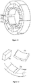
Figure 11 shows a first embodiment of the modular motor comprising (1) pole shoe, (2) stator tooth and (3) stator crown segment. -
Figure 12 shows details of the first embodiment of modular motor comprising (1) pole shoe, (2) stator tooth and (3) stator crown segment. -
Figure 13 shows a segment composed of optimized crown and tooth. -
Figure 14 shows the optimized stator shape wherein the shoe has a height greater than the stator tooth. -
Figure 15 shows another optimized stator shape wherein the shoe and the crown have a height greater than the stator tooth. - The following descriptions are given by way of example and not limiting the scope of the invention, and they will make the object of the present patent application more clearly understood.
- In the case of the enrichment of the ferromagnetic particles with manganese, this can be done by mixing the ferromagnetic powder (with a particle size in the order of 80 to 400 µm) with fine powder of pure Mn or Ferromanganese of high Mn content, in the ratio of 1: 0.1 to 2.
- The mixture of ferromagnetic powder and manganese powder is placed in a refractory crucible (loose powder, that is, uncompacted powder) and said crucible is taken to the oven. The atmosphere for the heat treatment must be sealed, with internal pressure in the tube of about 0.2 to 0.4 atm, in order to favor the sublimation/ deposition of the Mn on the iron particles. The atoms are incorporated in the surface of the iron particles due to the chemical potential gradient, either by mechanical contact between iron particles with the particles of Mn, or via the gas phase, since the Mn easily sublimates from the solid state (it has high sublimation vapor pressure). The difference lies in the fact that the enrichment occurs due to the chemical potential gradient of Mn between the treatment environment and the particles of iron. The desired enrichment should present the concentration profile as schematized in
Figure 1 . - In the present example, when it is desired to form an insulating film of Mn mixed oxide, after the enrichment treatment, the powder is cooled and a mixture of the enriched powder is prepared including up to 0.8% solid lubricant and from 0.1 to 3% of a reducible oxide in the form of a fine powder selected from iron oxide, nickel oxide, cobalt oxide or even copper oxide. The concentration profile is not affected by the compaction of the desired magnetic part, that is, the pressure applied in the compaction will not change the concentration profile. Thus, after compaction that should occur at pressures greater than 700 MPa, the presence of the Mn enriched layer will remain uniform throughout the surface of the particles.
- Since the oxidation of the layer has as its driving force the concentration gradient of manganese, it will be much more uniform in its thickness, as well as, the control of its thickness will depend only on the concentration of manganese and the amount of oxygen available in the interior of the part, which depends on the amount of oxygen-rich phase used as an oxygen carrier.
- After compaction molding, the parts are heat treated in a neutral or reactive atmosphere, at temperatures of about 500 °C.
- In another example, for the SMC materials generated from the enrichment of the particles with silicon, this occurs predominantly via mechanical contact between iron particles with the Si (or Si-rich) particles mixed together. However, the driving force for enrichment is the same as previously described, that is, the chemical potential gradient.
- To obtain these materials, ferromagnetic powder (having a particle size of the order of 80 to 400 µm) is mixed with fine Si or ferrosilicon powder with a content of greater than 20% by weight of Si (or other Si- carrying phase) in the ratio of 1: 0.1 to 1: 2.
- The mixture of the ferromagnetic powder and the Si powder is placed in a refractory crucible (loose powder, that is, uncompacted powder) and said crucible is taken to the oven. The atmosphere for the heat treatment must be inert with inert gas flow, at this step, avoiding Si oxidation, which would prevent the diffusion and formation of the enriched layer.
- In the present example, when it is desired to form an insulating film of Si mixed oxide, after the enrichment treatment, the powder is cooled and a mixture of the enriched powder is prepared containing up to 0.8% solid lubricant and from 0.5 to 3% of a reducible oxide powder selected from iron oxide, nickel oxide, cobalt oxide or copper oxide. The particle size of this oxygen-carrying oxide should preferably be about 10 to 100 times smaller than the particle size of the ferromagnetic powder used.
- Subsequently, the compaction of the parts is carried out using, for example, a compaction pressure above 700 MPa so that the maximum porosity is eliminated.
- After compaction, the parts are heat treated in a neutral or reactive atmosphere, at temperatures of about 500 °C.
- The present invention provides a process for coating ferromagnetic particles via dry powder mixing, using a cylindrical drum and steel spheres.
-
Figure 2 shows the drum for preparing mixtures, which is also used to spheroidize the ferromagnetic particles with enriched or non-enriched surface. - The ferromagnetic particles of interest have an average size ranging from 50 to 400 micrometers, depending on the application. Firstly, these particles pass through a spheroidization step in the cylindrical drum, wherein the steel spheres larger than 5 mm in diameter cause, as a function of the rotation of the drum, a mechanical conformation on the surface of the iron particles. This process promotes a change in the morphology of the particles, that is, the initial irregular surface of the particles becomes more rounded, or tend to spheroidicity.
-
Figure 3 shows the morphology of the particles before and after this forming process. This process of spheroidization of the ferromagnetic particles makes it possible to obtain more homogeneous and better anchored coatings, reducing the difficulties of the processing of said material and, consequently, reducing the magnetic losses in electromagnetic equipment constituted by the same. - After obtaining the spheroidized ferromagnetic particles, the oxide materials are incorporated into this same drum, and the coating process is performed.
- The insulating oxide materials are embodied by soft iron, manganese, nickel, magnesium, silicon, aluminum, titanium, boron and ferrite oxides, each imparting a different feature in the coating of the ferromagnetic particles.
- For the formation of the composites deriving from the mixture of iron particles and insulating oxides, oxides concentrations of 0.1 to 10% by volume, preferably by percentages of about 0.5 to 1% were used, wherein the oxides employed have size variations between 0.02 to 20 micrometers. Such a process is accomplished by the addition of oxide materials and ferromagnetic particles to the drum containing steel spheres. The tumbling process must occur until the particles are coated by deposition of the very small particle size oxide material on the surface of a much larger ferromagnetic particle.
-
Figure 4 shows the microstructure of a SMC sample composed of pure iron coated with Manganese Ferrite produced by the method described above. - Subsequently, the compacting of the parts is carried out, whose subsequent heat treatment is carried out in a neutral or reactive atmosphere, at temperatures of about 500 °C.
- By using ferromagnetic particles, preferably enriched and spheroidized (as described in paragraphs 32 and 44), the coating involving insulating oxides was performed from boron compounds, wherein boric acid (H3BO3) was used due to its characteristic of transformation into boron oxide and water at low temperatures. The manner of adding the boric acid was via liquid, through a solution containing boric acid and isopropyl alcohol. Said solution was prepared with the aid of a heating base with magnetic stirring, the concentration of boric acid in the solution can be from 1 g/L to 20 g/L and a ratio of powder mass per volume of solution of 2 g/L to 20 g/L can be used. The powder wetted with the solution is dried at room temperature and forced convection to increase the speed of the process.
- The layer formed of boric acid on the surface of the iron particles depends, among other factors, on the acid content in the solution and also on the ratios between iron particle mass and the volume of the solution. Iron particles with different percentages of boric acid show differences in the layer. A mass percentage of boric acid between 0.05% and 1.0%, preferably between 0.1% and 0.5% may be used.
- After the boric acid-containing powder was obtained, it is carried out a mixing with the solid lubricant, this being any compaction lubricant. The lubricant content may be between 0.1% and 1%, preferably between 0.3% and 0.5%. The function of the lubricant is to reduce the friction between the powder particles, thus avoiding the breakage of the boric acid layer, very high contents of lubricant tend to leave residual porosity after the heat treatment, reducing the magnetic permeability.
- In the present invention, the compacting pressure may be between 700 MPa and 1000 MPa, preferably between 800 MPa and 900 MPa. In order to increase the final density of the composite, the compaction can be made warmly.
- Finally, the compacted parts undergo a heat treatment in an inert or reactive atmosphere, at temperatures between 500 °C and 700 °C. During this heat treatment, the boric acid added via liquid to the surface of the ferromagnetic particles passes through chemical reactions at temperatures between 150 °C and 200 °C. The end product of these reactions is boron oxide and water vapor. Part of this generated vapor reacts with the surface of the ferromagnetic particles, finally obtaining an insulation formed of an iron oxide compound and boron.
- The coating involving iron boride is produced in two steps, the first is the boriding thermochemical treatment and the second is the separation of the boriding mixture and the iron particle. 80% Fe and 20% boriding mixture, by mass, were mixed; the boriding mixture can be commercial mixtures, considering the ease of subsequent separation. The heat treatment can be done at a temperature between 900 °C to 1100 °C, the holding time between 60 minutes to 240 minutes.
- After the boriding thermochemical treatment, it is necessary the separation of the ferromagnetic powder with the boride layer and the compounds of the boriding mixture. The ferromagnetic powder with a layer of iron boride obtained should preferably contain the Fe2B phase, as shown in
Figure 5e , and the layer thickness may be between 0.1 and 2 µm. - The obtained borided powder is then mixed with lubricant. The compacting pressure may be between 700 MPa and 1000 MPa, preferably between 800 MPa and 900 MPa. The heat treatment of the SMCs produced with the borided ferromagnetic powder may be carried out at temperatures between 500 °C and 1100 °C, preferably between 700 °C and 900 °C.
- Table 1 shows the results of density, electrical resistivity and magnetic properties of SMCs developed with electrical insulation of boron compounds:
Table 1: Density, electrical resistivity and magnetic properties. Sample Heat treatment temperature [°C] Density [g/cm3] Electrical resistivity [µΩ.m] µmax Losses [W/kg] (800 mT - 60Hz) Fe2B 900 7.01 0.37 330 25.7 0.1% H3BO3 600 7.28 3.28 308 5.9 0.3% H3BO3 7.22 7.80 218 5.7 0.1% H3BO3 500 7.24 54.07 288 6.8 0.3% H3BO3 7.13 62.04 200 6.4 - The execution of the process for coating the ferromagnetic particles, preferably spheroidized and enriched (as described in paragraphs 32 and 44), with glassy suspension of submicrometric particles (
Figure 7 ), imparted a higher electrical resistance to the coating, thus being possible to reduce the coating thickness in order to maximize the magnetic material and increase its efficiency. It was also observed an increase in the thermal resistance of the coating, allowing higher processing temperatures of the material. The iron particles that were coated with glassy suspension follow the following steps: - 1- Non-metallic particles (for example, Al2O3, TiO2, ZrO2, WC, B2O3) are dispersed in an aqueous solution of alkali metal silicate (for example, Na2O·nSiO2, K2O·mSiO2 or a mixture thereof);
- 2- A ferromagnetic base powder is immersed in this silicate dispersion; the spare liquid is removed, remaining the ferromagnetic powder soaked by the silicate dispersion;
- 3- The product is dried, leaving the ferromagnetic powder coated by a solid layer of alkali metal silicate with particles dispersed in the glassy phase.
- The viscosity of the coating solution made in
Step 1 increases with increasing concentrations of silicate and dispersed particles. Viscosity also increases with decreasing mean particle size. The higher the viscosity of said solution and its wettability in the ferromagnetic phase, the greater the thickness of the layer deposited on the base powder. - The higher the ionic radius of the alkali metal of the silicate (Fr > Cs > Rb > K > Na > Li), the greater the electrical resistivity of the silicate, allowing a lower thickness of insulation layer to be deposited on the particles to decrease the parasitic currents. In addition, various properties associated with alkaline ion movement of a mixture of different silicates (for example, (1-X)K2O·XNa2O·nSiO2) have large variations with orders of magnitude of difference compared to the isolated precursors. For example, a mixture of the form (1-X)Na2O·XK2O·4SiO2, with X about 0.5, exhibits a resistivity almost 10 times greater than a pure sodium or potassium silicate.
- The smaller the submicrometric particles dispersed in
Step 1, the greater their specific area, making their thermal absorption greater during the heat treatment. This also increases the viscosity of the glassy phase after it reaches the glass transition. These effects allow an increase in the heat treatment temperature without loss of the integrity of the coating. - To illustrate the effect of the suspended particles on the coating during the heat treatment,
Figure 8 shows a thermogravimetric analysis under oxidizing atmosphere performed on iron powder uncoated (a), coated only with sodium silicate (b) and with glassy suspension of ceramic particles of 1.36 µm (c), 0.02 µm (d), 0.16 µm (e) and 0.1 µm (f). While the uncoated iron powder begins to oxidize (to increase its mass) significantly from 500 °C, the material coated only with sodium silicate maintains its oxidation resistance up to approximately 600 °C. Samples containing ceramic particles dispersed in the glassy phase show the appreciable increase in oxidation rate only above 650 °C, depending on the average particle size. The curves show an increase in the oxidation temperature of the samples, indicating that the glassy coating coats the entire surface of the particles, preventing the oxygen from interacting with the iron. The oxidation of the particles only becomes appreciable when the glassy coating decreases its viscosity sufficiently to flow out of the surface of the iron. When ceramic particles are dispersed in the sodium silicate, they absorb part of the thermal energy, causing it to take longer to achieve the glass transition of the coating. After this glass transition, the particles further increase the viscosity of the silicate, making it difficult to flow into the pores and keeping the material longer between the ferromagnetic particles. - Also during heat treatment, the particles dispersed in the silicate act as activators of the crystallization of the glassy phase, this effect being intensified for smaller particles. The crystalline phase of the silicates has a higher melting temperature than the temperature at which their amorphous form is fluidified. By adjusting the heating rate, temperature and holding time or by performing cooling and heating cycles, the use of the product produced by this invention can be processed at much higher temperatures than the simple use of pure glassy coatings.
- For even higher temperatures, depending on the composition of the dispersed particles and the silicate used, they begin to dissolve in the glassy phase forming more viscous and resistive compounds during the heat treatment. For example, treated at a temperature above 800 °C, alumina particles dispersed in sodium silicate dissolve forming sodium aluminosilicate. Thus, by adjusting parameters of the heat treatment cycle, such as heating rate, temperature and holding time, it is possible to optimize the properties for each object produced by the process described in this invention.
- Iron particles having a mean diameter of 222 µm were dispersed in an aqueous solution of sodium silicate (11 mg/ml) with 11 mg/ml of particles of Al2O3 having a mean diameter of 20 nm dispersed. The spare solution is discarded and the particulate material is dried at 85 °C for 2 hours in a vacuum oven.
- The product is mixed with 0.5% by weight of lubricant and compacted via uniaxial compaction at 800 MPa. The compacted green body is heat treated under inert atmosphere with a level at 400 °C for 30 minutes for extraction of the lubricant, and then a level at 600 °C for 30 minutes.
-
Figure 9 shows an electron microscopy image of a section prepared for metallography of the component produced with the respective product described in this example. It is possible to identify an insulating phase completely permeating the iron particles. This product had a resistivity of 12.39 µΩ.m. - For the purpose of comparison, the same base iron powder having a mean size of 222 µm was coated only by the sodium silicate without the nanoparticle dispersion, compacted and heat treated under the same parameters cited in this example. The electrical resistivity value of this material was 1.28 µΩ.m, indicating that the dispersion of nanoparticles in the glassy phase increased the integrity and electrical resistivity of the material.
-
Figure 10 shows the measurement of the magnetic losses of these two materials measured for an induction frequency of 60 Hz. Under a maximum induction of 450 mT, for example, the product containing the alumina nanoparticles dispersed in the sodium silicate presents 84% of the total losses of the product coated only with sodium silicate. - Table 2 shows the total loss value measured for an induction frequency of 60 Hz and maximum induction of 450 mT for materials produced as described in this example, with and without alumina nanoparticles, with final level of heat treatment at T = 500 °C and 600 °C.
Table 2: Total losses. Iron Coated with Sodium Silicate Thermal Level Total Losses without nanoparticles 500 °C 2.55 W/kg with nanoparticles 500 °C 2.57 W/kg without nanoparticles 600 °C 2.69 W/kg with nanoparticles 600 °C 2.26 W/kg - The increase in heat treatment temperature from 500 °C to 600 °C causes the flow of sodium silicate without nanoparticles to the pores, as discussed above, allowing contact between the iron particles and increasing the total losses due to parasitic currents. This not only does not occur at 600 °C when using the process described in this invention, dispersing nanoparticles in the silicate, as at a higher temperature there is a greater relaxation of the residual stresses generated during compaction and exhibiting a decrease of 12% of total losses in relation to the sample treated at 500 °C.
- As an example of application of the SMCs materials presented in this invention, it is proposed the construction of an electric motor comprising stator tooth, pole shoe and stator crown.
- The electric motor manufactured with the use of the material constituting iron particles and insulating presents some advantages in its constructive form, such as modularity and three-dimensional design.
Figures 11, 12 and13 present the basic concept of motor design and modularization. Said modularity enables the use of preformed coils without the need to insert the coils through the openings of the groove. Such an assembly allows the modularization of the motor, that is, the motor is composed of embedded parts and not of a single entire part. In this way, the cost of producing the motor can be reduced due to the lower cost of making the coils, as well as additional rolling costs. - The pole shoe located on the motor stator is embodied as comprising an optimized two- or three-dimensional shape for the magnetic flow lines, reducing iron losses and material volume while increasing motor performance, as shown in
Figure 14 . The optimized shape for the flow lines comprises being adopted for the sides of the shoe or towards the height of the shoe, wherein the shoe has a height greater than the stator tooth, as also indicated inFigure 15 . - The assembly process of the electric motor comprising an association between the stator crown segments, an association between the stator tooth and the stator crown segment, and an association between the pole shoe and the stator tooth, wherein the stator crown segment comprises a housing, for example, dovetail type, for association with the upper surface of the stator tooth, and wherein the pole shoe has a housing for association with the lower part of the stator tooth. Such an assembly allows the modularization of the motor, that is, the motor is composed of embedded parts and not of a single entire part.
- A mixture (ratio 1: 1) of spheroidized particles of pure iron and FeMn (with high Mn content) were conditioned in a refractory crucible and heat-treated in a resistive oven. The treatment temperature was 700 °C, the oven atmosphere being inert and sealed. During this treatment the sublimation/ deposition of the Mn on the iron particles occurred, wherein a percentage of manganese of about 12% could be quantified in the surface of the iron particles.
- After the heat treatment step, it was necessary to carry out the separation of the enriched powder and the FeMn powder. As the average particle diameter of the two powders is distinct, 220 micrometers to the iron powder and 100 micrometers to the FeMn powder, a sieving can be performed to obtain the enriched iron powder.
- Subsequently, the enriched iron powder was coated with boric acid (H3BO3) to promote the oxidation of the enriched surface during the heat treatment. This oxidation is caused by the release of water that occurs during the transformations of boric acid at low temperatures.
- The manner of adding boric acid to the enriched iron powder was via liquid, through a solution containing boric acid and isopropyl alcohol. Said solution was prepared with the aid of a heating base with magnetic stirring, wherein the concentration of boric acid in the solution was 0.8 g/L and the mass percentage of boric acid in the enriched iron powder was 0.1%. The powder was wetted with this solution, and then dried at room temperature with forced convection to increase the speed of the process.
- After the boric acid-containing powder was obtained, it was mixed with 0.3% solid lubricant. The compacting of the specimens was performed at a pressure of 800 MPa and, finally, the compacted parts underwent a heat treatment in an inert atmosphere, at a temperature of 500 °C for 30 minutes. During this heat treatment, the boric acid added via liquid to the surface of the ferromagnetic particles passes through chemical reactions at temperatures between 150 °C and 200 °C. The end product of these reactions is boron oxide and water vapor, where part of that vapor reacts with the surface of the enriched iron particles thus forming a mixed oxide of iron and manganese.
- Table 3 shows the results of density, electrical resistivity and magnetic properties of the SMCs developed with electrical insulation of mixed oxides of iron and manganese and boron oxide:
Table 3: Density, electrical resistivity and magnetic properties. Sample Heat treatment temperature [°C] Density [g/cm3] Electrical resistivity [µΩ.m] Losses [W/kg] (800 mT - 60Hz) Fe enriched with Mn +0.1% H3BO3 500 6.95 295 8 - A mixture (ratio 1: 1) of spheroidized particles of pure iron and FeMn (with high Mn content) were conditioned in a refractory crucible and heat-treated in a resistive oven. The treatment temperature was 700 °C, the oven atmosphere being inert and sealed. During this treatment the sublimation/ deposition of the Mn on the iron particles occurred, wherein a percentage of manganese of about 15% could be quantified in the surface of the iron particles.
- After the heat treatment step, it was necessary to carry out the separation of the enriched powder and the FeMn powder. As the average particle diameter of the two powders is distinct, 220 micrometers to the iron powder and 100 micrometers to the FeMn powder, a sieving can be performed to obtain the enriched iron powder.
- Subsequently, the powder was subjected to the coating process with non-metallic particles dispersed in alkali metal silicate, as described in item b) of the second object of the present invention and in more detail in paragraph 59, using sodium silicate and alumina nanoparticles (20 nm) for the coating suspension, both at a concentration of 1 mg/ml. The powder was dried at a temperature of 75 °C under vacuum forming a manganese-enriched iron composite coated by 0.02% by mass of sodium silicate with dispersed alumina nanoparticles.
- The composite formed was mixed at 0.3% by mass of lubricant, compacted at a pressure of 800 MPa and, finally, treated under oxidizing atmosphere at 500 °C for 30 minutes. During this heat treatment the glassy composite of the coating, in addition to providing electrical insulation, releases water of crystallization of the silicate, oxidizing the surface of the enriched iron particles and forming a mixed oxide of iron and manganese, which provides an even greater electrical resistivity for the material.
- Table 4 shows the results of density, electrical resistivity and magnetic properties of the SMCs developed with electrical insulation of mixed oxides of iron and manganese and sodium silicate with dispersion of alumina nanoparticles:
Table 4: Density, electrical resistivity and magnetic properties. Sample Heat treatment temperature [°C] Density [g/cm3] Electrical resistivity [µΩ.m] Losses [W/kg] (800 mT - 60Hz) Fe enriched with Mn +0.02% liquid glass 500 6.95 18 8 - The examples shown herein are for the sole purpose of exemplifying one of the innumerable ways of carrying out the invention, but without limiting the scope thereof.
Claims (17)
- Soft magnetic composite composed of ferromagnetic particles coated with inorganic material capable of generating electrical insulation between them, minimizing the effect of parasitic currents in electrical applications, characterized by the fact that it is obtained by a process comprising the following sub-steps:I. coating of the ferromagnetic particles with inorganic material;II. mechanical conformation of the particulate material composed of the ferromagnetic particles coated with inorganic material; andIII. heat treatment of the composite formed by the ferromagnetic particles coated with inorganic material.
- Process, according to claim 1, characterized by the fact that the ferromagnetic particles are formed by materials with high relative magnetic permeability such as iron, nickel, cobalt and their alloys; the ferromagnetic particles being provided with an average size between 50 µm and 500 µm and more preferably between 150 µm and 300 µm.
- Process, according to claims 1 and 2, characterized by the fact that the ferromagnetic particles are subjected to a previous step of spheroidization by means of tumbling, in which these ferromagnetic particles are subjected to a tumbling-drum provided with metal spheres.
- Process, according to claims 1 and 2, characterized by the fact that the coating of inorganic material is obtained by a process wherein the ferromagnetic particles undergo a superficial enrichment with chemical elements such as manganese, silicon, aluminum, chromium, titanium, tantalum, vanadium and the like, which form stable compounds of high electrical resistivity (oxides, nitrides, carbonitrides and borides); followed by a subsequent oxidation process of the layers enriched by an oxidizing agent during the heat treatment, which is a reducible oxide selected from iron oxide, nickel oxide, cobalt oxide and copper oxide, or a compound which releases water vapor during, such as boric acid or alkali metal silicate.
- Process, according to claim 4, characterized by the fact that the step of enriching the ferromagnetic particles with manganese. This enrichment process comprises the sub-steps of:I. mixing the ferromagnetic particles with fine powder of pure Mn or ferromanganese of high Mn content in the ratio of 1: 0.1 to 2;II. heat treatment of the mixture of powders in a sealed atmosphere at a temperature that may range from 500 °C to 1000 °C, in order to promote the incorporation of the manganese atoms on the surface of the ferromagnetic particles (enrichment) due to the chemical potential gradient, both by mechanical contact, and via gas phase from the sublimation of manganese;III. separation of enriched ferromagnetic particles from the FeMn powder or iron powder with high concentration of manganese.
- Process, according to claim 4, characterized by the fact that the step of enriching the ferromagnetic particles with silicon. This enrichment process comprises the sub-steps of:I. mixing the ferromagnetic particles with fine Si or Ferrosilicon powder having a content higher than 20% by weight of Si (or another Si-carrying phase), in the ratio of 1: 0.1 to 1: 2;II. heat treatment of the powder mixture in reducing atmosphere with reducing gas flow;III. separation of enriched ferromagnetic particles from the fine Si or Ferrosilicon powder.
- Process, according to claims 1 and 4, characterized by the fact that the oxidizing agent of the enriched layer mixed is a reducible oxide powder less stable than the oxide formed by the element incorporated in the enriched layer, such as iron oxide, nickel oxide, cobalt oxide, copper oxide, or the like; and these are mixed by dry tumbling using a concentration of oxides of from 0.01 % to 10% by volume, more preferably from 0.1 % to 1%.
- Process, according to claim 4, characterized by the fact that the oxidizing agent of the enriched layer is a boron compound (for example, boric acid, metaboric acid, tetraboric acid, ammonium tetraborate, pentaborate, peroxyborate, or the like), deposited by liquid route, wherein the ferromagnetic particles are wetted with a solution comprising the boron compound in a ratio of ferromagnetic particle mass per solution volume between 2 g/L and 20 g/L.
- Process, according to claim 8, characterized by the fact that the solution comprising the boron compound is prepared from the mixture of boric acid and isopropyl alcohol, the mass percentage of boric acid in the solution being between 0.05% to 1.0%, preferably between 0.1% to 0.5%.
- Process, according to claim 8, characterized by the fact that the solution comprising the boron compound is prepared from the mixture of boric acid in aqueous solution of alkali metal silicate, the mass percentage of boric acid in the solution being between 0.05% and 1.0% and the concentration of alkali metal silicate being between 0.001 mg/ml and 15 mg/ml.
- Process, according to claims 1 and 2, characterized by the fact that the coating of the ferromagnetic particles with insulating inorganic material occurs via boriding, which comprises the sub-steps of:I. mixing the ferromagnetic particles with a boriding mixture, in the mass ratio of 80% ferromagnetic particles and 20% boriding mixture;II. heat treating the mixture obtained in sub-step (I) at a temperature between 900 °C and 1100 °C; andIII. separating the ferromagnetic particles with the boride layer obtained in sub-step (II) and the compounds of the boriding mixture;
the boride layer being the insulating inorganic material coating of the ferromagnetic particles. - Process, according to claims 1 and 2, characterized by the fact that the coating of the ferromagnetic particles with insulating inorganic material occurs via a glassy suspension formed by non-metallic particles dispersed in alkali metal silicate, which comprises the sub-steps of:I. dispersing the non-metallic particles into an aqueous solution of alkali metal silicate;II. wetting the ferromagnetic particles by said alkali metal silicate solution with dispersed non-metallic particles obtained in (I); andIII. drying the ferromagnetic particles wetted by the alkali metal silicate solution with dispersed non-metallic particles obtained in (II);
and wherein:
the non-metallic particles are formed by high electrical resistivity ceramic materials selected from oxides, carbides, fluorides or the like, the average size of the non-metallic particles being between 0.005 µm and 1 µm and more preferably between 0.01 µm and 0,4 µm. - Process, according to claim 12, characterized by the fact that the alkali metal silicate solution is composed of the water dilution of one or more silicates, the molar ratio of the silica molecules to the alkali metal oxides of the alkali metal silicates being between 0.5 and 8 and more preferably between 1.5 and 4.
- Process, according to claims 12 and 13, characterized by the fact that the alkali metal silicate solution contains a concentration of silicate or mixture of silicates between 0.001 mg/ml and 15 mg/ml, and more preferably between 0.01 mg/ml and 1 mg/ml.
- Process, according to claims 12, 13 and 14, characterized by the fact that the concentration of non-metallic particles dispersed in the alkali metal silicate solution is between 0.001 mg/ml and 15 mg/ml, and more preferably between 0.01 mg/ml and 1 mg/ml.
- Process, according to claims 4, 12, 13 and 14, characterized by the fact that the oxidizing agent of the enriched layer is the alkali metal silicate with concentration of non-metallic particles dispersed in the coating alkali metal silicate solution between 0 mg/ml and 15 mg/ml, and more preferably between 0 mg/ml and 1 mg/ml.
- Processing of the soft magnetic composites, formed by the ferromagnetic particles enriched and mixed with an oxidizing agent, according to claims 1, 4 to 10 and 16, characterized by the fact that the heat treatment of the compacted composite is carried out with a temperature between 100 °C and 1100 °C, more preferably between 500 °C and 800 °C, imparting mechanical strength to the composite and ensuring the oxidation of the enriched layer and generating the electrical insulation between the ferromagnetic particles.
Applications Claiming Priority (3)
| Application Number | Priority Date | Filing Date | Title |
|---|---|---|---|
| BR102016019681A BR102016019681A8 (en) | 2016-08-25 | 2016-08-25 | particle coating processes, particle surface layer enrichment process, electric motor and electric motor assembly process |
| BR102017018203-7A BR102017018203A2 (en) | 2017-08-24 | 2017-08-24 | SURFACE LAYERS OF FERROMAGNETIC PARTICLES FOR SOFT MAGNETIC COMPOSITES (SMCS) |
| PCT/BR2017/050245 WO2018035595A1 (en) | 2016-08-25 | 2017-08-25 | Ferromagnetic particle surface coating layers for obtaining soft magnetic composites (smcs) |
Publications (2)
| Publication Number | Publication Date |
|---|---|
| EP3505276A1 true EP3505276A1 (en) | 2019-07-03 |
| EP3505276A4 EP3505276A4 (en) | 2020-07-29 |
Family
ID=61245777
Family Applications (1)
| Application Number | Title | Priority Date | Filing Date |
|---|---|---|---|
| EP17842476.8A Withdrawn EP3505276A4 (en) | 2016-08-25 | 2017-08-25 | Ferromagnetic particle surface coating layers for obtaining soft magnetic composites (smcs) |
Country Status (5)
| Country | Link |
|---|---|
| US (1) | US20190228892A1 (en) |
| EP (1) | EP3505276A4 (en) |
| JP (1) | JP2019532175A (en) |
| CN (1) | CN109641270A (en) |
| WO (1) | WO2018035595A1 (en) |
Families Citing this family (7)
| Publication number | Priority date | Publication date | Assignee | Title |
|---|---|---|---|---|
| CN110266152B (en) * | 2019-07-19 | 2022-07-26 | 绵阳西磁磁电有限公司 | Method for coating composite soft magnetic material on stator and high-speed permanent magnet motor thereof |
| CN112139489A (en) * | 2020-09-27 | 2020-12-29 | 蔡国庆 | Preparation method of iron-tantalum pentoxide biological composite material |
| MX2024001342A (en) * | 2021-07-29 | 2024-07-15 | Horizon Tech | Magnetic compositions and methods of making and using the same. |
| CN116079049B (en) * | 2021-10-26 | 2026-02-27 | 横店集团东磁股份有限公司 | Antioxidant coating solution and its application |
| CN117265483B (en) * | 2023-07-30 | 2026-05-05 | 广西电网有限责任公司电力科学研究院 | A high coercivity hard magnetic oxide semiconductor thin film with perpendicular magnetic anisotropy and its preparation method |
| CN117542599B (en) * | 2023-10-23 | 2024-06-14 | 江苏普隆磁电有限公司 | Corrosion-resistant NdFeB magnet and preparation method thereof |
| CN118231079B (en) * | 2024-04-16 | 2024-09-24 | 中南大学 | A FeSi soft magnetic composite material |
Family Cites Families (15)
| Publication number | Priority date | Publication date | Assignee | Title |
|---|---|---|---|---|
| JP2003142310A (en) * | 2001-11-02 | 2003-05-16 | Daido Steel Co Ltd | Powder magnetic core having high electric resistance and method of manufacturing the same |
| JP2003197416A (en) * | 2001-12-26 | 2003-07-11 | Daido Steel Co Ltd | Dust core manufacturing method, dust core manufactured by the method |
| JP4400728B2 (en) * | 2004-03-16 | 2010-01-20 | 戸田工業株式会社 | SOFT MAGNETIC MATERIAL AND PROCESS FOR PRODUCING THE SAME |
| CN101927344B (en) * | 2004-09-06 | 2013-01-30 | 大冶美有限公司 | Method for producing soft magnetic metal powder coated with mg-containing oxidized film and method for producing composite soft magnetic material using the powder |
| CN101056729A (en) * | 2004-09-06 | 2007-10-17 | 三菱综合材料Pmg株式会社 | Method for producing Mg-containing oxide film-coated soft magnetic metal powder and method for producing composite soft magnetic material using the powder |
| JP4650073B2 (en) * | 2005-04-15 | 2011-03-16 | 住友電気工業株式会社 | Method for producing soft magnetic material, soft magnetic material and dust core |
| CA2610602C (en) * | 2005-06-15 | 2014-02-18 | Bjorn Skarman | Soft magnetic composite materials |
| JP4560077B2 (en) * | 2007-11-12 | 2010-10-13 | トヨタ自動車株式会社 | Powder for magnetic core and method for producing powder for magnetic core |
| JP4802182B2 (en) * | 2007-12-14 | 2011-10-26 | Jfeスチール株式会社 | Iron powder for dust cores |
| JP4422773B2 (en) * | 2008-04-18 | 2010-02-24 | トヨタ自動車株式会社 | Powder for powder magnetic core and manufacturing method thereof |
| US8911663B2 (en) * | 2009-03-05 | 2014-12-16 | Quebec Metal Powders, Ltd. | Insulated iron-base powder for soft magnetic applications |
| JP2012107330A (en) * | 2010-10-26 | 2012-06-07 | Sumitomo Electric Ind Ltd | Soft magnetic powder, granulated powder, dust core, electromagnetic component, and method for manufacturing dust core |
| JP2012253317A (en) * | 2011-05-09 | 2012-12-20 | Kobe Steel Ltd | Manufacturing method of dust core, and dust core manufactured by the method |
| WO2013159558A1 (en) * | 2012-04-26 | 2013-10-31 | The Hong Kong University Of Science And Technology | Soft magnetic composite materials |
| CN103240411B (en) * | 2013-05-20 | 2014-11-12 | 哈尔滨工业大学 | Production methods of inorganic-organic insulation layer soft magnetic composites |
-
2017
- 2017-08-25 WO PCT/BR2017/050245 patent/WO2018035595A1/en not_active Ceased
- 2017-08-25 JP JP2019510827A patent/JP2019532175A/en active Pending
- 2017-08-25 US US16/328,011 patent/US20190228892A1/en not_active Abandoned
- 2017-08-25 EP EP17842476.8A patent/EP3505276A4/en not_active Withdrawn
- 2017-08-25 CN CN201780051985.2A patent/CN109641270A/en active Pending
Also Published As
| Publication number | Publication date |
|---|---|
| JP2019532175A (en) | 2019-11-07 |
| EP3505276A4 (en) | 2020-07-29 |
| CN109641270A (en) | 2019-04-16 |
| WO2018035595A1 (en) | 2018-03-01 |
| US20190228892A1 (en) | 2019-07-25 |
Similar Documents
| Publication | Publication Date | Title |
|---|---|---|
| US20190228892A1 (en) | Coating Layers of Ferromagnetic Particles Surfaces for Obtaining Soft Magnetic Composites (SMCS) | |
| JP4431681B2 (en) | Metal-coated carbon material and carbon-metal composite material using the same | |
| CN102548932B (en) | The coated hard particles of toughness being fixedly arranged in tough matrix material | |
| US10741316B2 (en) | Ferromagnetic powder composition and method for its production | |
| US8481178B2 (en) | Iron powder coated with Mg-containing oxide film | |
| EP2227344B1 (en) | Powder for magnetic core, method for manufacturing powder for magnetic core, and dust core | |
| JP6799196B6 (en) | Rare earth bond magnetic powder, its manufacturing method and bond magnet | |
| US8911663B2 (en) | Insulated iron-base powder for soft magnetic applications | |
| CN100439012C (en) | Iron-based soft magnetic powder | |
| US20100150768A1 (en) | Method for producing metal powder for dust core and method for manufacturing dust core | |
| Marocco et al. | Metal-ceramic composite materials from zeolite precursor | |
| TWI628293B (en) | Soft magnetic powder mix | |
| CA2526886C (en) | Iron base sintered alloy having highly densified and hardened surface, and producing method thereof | |
| KR102712731B1 (en) | TiC particle-reinforced Fe-based composite material and its manufacturing method | |
| Cheng et al. | Superior core-shell Fe-Al magnetic abrasive prepared by controlled pack cementation | |
| CN114921714A (en) | Y 2 O 3 Nanoparticle dispersion strengthened steel and preparation method thereof | |
| BR102017018203A2 (en) | SURFACE LAYERS OF FERROMAGNETIC PARTICLES FOR SOFT MAGNETIC COMPOSITES (SMCS) | |
| US11085109B2 (en) | Method of manufacturing a crystalline aluminum-iron-silicon alloy | |
| Xiao et al. | Influence of sintering temperature on the interfacial behavior of Ti3Al (Si) C2 ceramic and Ti6Al4V alloy | |
| JP2007231331A (en) | Metal powder for dust core and method for producing dust core | |
| Inoue et al. | Fabrication and cyclic oxidation behavior of Al4SiC4–SiC composite carbides on carbothermal reduction of kaolinite | |
| JP2599284B2 (en) | Manufacturing method of soft sintered magnetic material | |
| BR102016019681A2 (en) | PARTICLE COATING PROCESSES, PARTICLE SURFACE LAYER PROCESS, ELECTRIC MOTOR AND ELECTRIC MOTOR ASSEMBLY PROCESS | |
| JP2006233325A (en) | Mg-containing iron oxide coated iron powder | |
| Mani | Development of Fe-50Co alloy and its composites by spark plasma sintering |
Legal Events
| Date | Code | Title | Description |
|---|---|---|---|
| STAA | Information on the status of an ep patent application or granted ep patent |
Free format text: STATUS: THE INTERNATIONAL PUBLICATION HAS BEEN MADE |
|
| PUAI | Public reference made under article 153(3) epc to a published international application that has entered the european phase |
Free format text: ORIGINAL CODE: 0009012 |
|
| STAA | Information on the status of an ep patent application or granted ep patent |
Free format text: STATUS: REQUEST FOR EXAMINATION WAS MADE |
|
| 17P | Request for examination filed |
Effective date: 20190222 |
|
| AK | Designated contracting states |
Kind code of ref document: A1 Designated state(s): AL AT BE BG CH CY CZ DE DK EE ES FI FR GB GR HR HU IE IS IT LI LT LU LV MC MK MT NL NO PL PT RO RS SE SI SK SM TR |
|
| AX | Request for extension of the european patent |
Extension state: BA ME |
|
| DAV | Request for validation of the european patent (deleted) | ||
| DAX | Request for extension of the european patent (deleted) | ||
| RIC1 | Information provided on ipc code assigned before grant |
Ipc: H01F 1/24 20060101ALI20200127BHEP Ipc: H01F 1/22 20060101ALI20200127BHEP Ipc: B22F 1/02 20060101AFI20200127BHEP Ipc: H01F 1/33 20060101ALI20200127BHEP |
|
| A4 | Supplementary search report drawn up and despatched |
Effective date: 20200618 |
|
| RIC1 | Information provided on ipc code assigned before grant |
Ipc: B22F 1/02 20060101AFI20200618BHEP Ipc: H01F 1/33 20060101ALI20200618BHEP Ipc: H01F 1/24 20060101ALI20200618BHEP Ipc: H01F 1/22 20060101ALI20200618BHEP |
|
| RA4 | Supplementary search report drawn up and despatched (corrected) |
Effective date: 20200626 |
|
| RIC1 | Information provided on ipc code assigned before grant |
Ipc: H01F 1/33 20060101ALI20200622BHEP Ipc: H01F 1/22 20060101ALI20200622BHEP Ipc: H01F 1/24 20060101ALI20200622BHEP Ipc: B22F 1/02 20060101AFI20200622BHEP |
|
| STAA | Information on the status of an ep patent application or granted ep patent |
Free format text: STATUS: THE APPLICATION IS DEEMED TO BE WITHDRAWN |
|
| 18D | Application deemed to be withdrawn |
Effective date: 20210126 |