EP3505266B1 - Hot stamping die apparatus - Google Patents
Hot stamping die apparatus Download PDFInfo
- Publication number
- EP3505266B1 EP3505266B1 EP18190222.2A EP18190222A EP3505266B1 EP 3505266 B1 EP3505266 B1 EP 3505266B1 EP 18190222 A EP18190222 A EP 18190222A EP 3505266 B1 EP3505266 B1 EP 3505266B1
- Authority
- EP
- European Patent Office
- Prior art keywords
- sub
- die
- cooling channel
- assembly
- plates
- Prior art date
- Legal status (The legal status is an assumption and is not a legal conclusion. Google has not performed a legal analysis and makes no representation as to the accuracy of the status listed.)
- Active
Links
Images




Classifications
-
- B—PERFORMING OPERATIONS; TRANSPORTING
- B21—MECHANICAL METAL-WORKING WITHOUT ESSENTIALLY REMOVING MATERIAL; PUNCHING METAL
- B21D—WORKING OR PROCESSING OF SHEET METAL OR METAL TUBES, RODS OR PROFILES WITHOUT ESSENTIALLY REMOVING MATERIAL; PUNCHING METAL
- B21D37/00—Tools as parts of machines covered by this subclass
- B21D37/02—Die constructions enabling assembly of the die parts in different ways
-
- B—PERFORMING OPERATIONS; TRANSPORTING
- B21—MECHANICAL METAL-WORKING WITHOUT ESSENTIALLY REMOVING MATERIAL; PUNCHING METAL
- B21D—WORKING OR PROCESSING OF SHEET METAL OR METAL TUBES, RODS OR PROFILES WITHOUT ESSENTIALLY REMOVING MATERIAL; PUNCHING METAL
- B21D22/00—Shaping without cutting, by stamping, spinning, or deep-drawing
- B21D22/02—Stamping using rigid devices or tools
- B21D22/022—Stamping using rigid devices or tools by heating the blank or stamping associated with heat treatment
-
- B—PERFORMING OPERATIONS; TRANSPORTING
- B21—MECHANICAL METAL-WORKING WITHOUT ESSENTIALLY REMOVING MATERIAL; PUNCHING METAL
- B21D—WORKING OR PROCESSING OF SHEET METAL OR METAL TUBES, RODS OR PROFILES WITHOUT ESSENTIALLY REMOVING MATERIAL; PUNCHING METAL
- B21D22/00—Shaping without cutting, by stamping, spinning, or deep-drawing
- B21D22/02—Stamping using rigid devices or tools
-
- B—PERFORMING OPERATIONS; TRANSPORTING
- B21—MECHANICAL METAL-WORKING WITHOUT ESSENTIALLY REMOVING MATERIAL; PUNCHING METAL
- B21D—WORKING OR PROCESSING OF SHEET METAL OR METAL TUBES, RODS OR PROFILES WITHOUT ESSENTIALLY REMOVING MATERIAL; PUNCHING METAL
- B21D22/00—Shaping without cutting, by stamping, spinning, or deep-drawing
- B21D22/20—Deep-drawing
-
- B—PERFORMING OPERATIONS; TRANSPORTING
- B21—MECHANICAL METAL-WORKING WITHOUT ESSENTIALLY REMOVING MATERIAL; PUNCHING METAL
- B21D—WORKING OR PROCESSING OF SHEET METAL OR METAL TUBES, RODS OR PROFILES WITHOUT ESSENTIALLY REMOVING MATERIAL; PUNCHING METAL
- B21D37/00—Tools as parts of machines covered by this subclass
-
- B—PERFORMING OPERATIONS; TRANSPORTING
- B21—MECHANICAL METAL-WORKING WITHOUT ESSENTIALLY REMOVING MATERIAL; PUNCHING METAL
- B21D—WORKING OR PROCESSING OF SHEET METAL OR METAL TUBES, RODS OR PROFILES WITHOUT ESSENTIALLY REMOVING MATERIAL; PUNCHING METAL
- B21D37/00—Tools as parts of machines covered by this subclass
- B21D37/10—Die sets; Pillar guides
-
- B—PERFORMING OPERATIONS; TRANSPORTING
- B21—MECHANICAL METAL-WORKING WITHOUT ESSENTIALLY REMOVING MATERIAL; PUNCHING METAL
- B21D—WORKING OR PROCESSING OF SHEET METAL OR METAL TUBES, RODS OR PROFILES WITHOUT ESSENTIALLY REMOVING MATERIAL; PUNCHING METAL
- B21D37/00—Tools as parts of machines covered by this subclass
- B21D37/16—Heating or cooling
-
- C—CHEMISTRY; METALLURGY
- C21—METALLURGY OF IRON
- C21D—MODIFYING THE PHYSICAL STRUCTURE OF FERROUS METALS; GENERAL DEVICES FOR HEAT TREATMENT OF FERROUS OR NON-FERROUS METALS OR ALLOYS; MAKING METAL MALLEABLE, e.g. BY DECARBURISATION OR TEMPERING
- C21D1/00—General methods or devices for heat treatment, e.g. annealing, hardening, quenching or tempering
- C21D1/34—Methods of heating
-
- C—CHEMISTRY; METALLURGY
- C21—METALLURGY OF IRON
- C21D—MODIFYING THE PHYSICAL STRUCTURE OF FERROUS METALS; GENERAL DEVICES FOR HEAT TREATMENT OF FERROUS OR NON-FERROUS METALS OR ALLOYS; MAKING METAL MALLEABLE, e.g. BY DECARBURISATION OR TEMPERING
- C21D9/00—Heat treatment, e.g. annealing, hardening, quenching or tempering, adapted for particular articles; Furnaces therefor
-
- C—CHEMISTRY; METALLURGY
- C21—METALLURGY OF IRON
- C21D—MODIFYING THE PHYSICAL STRUCTURE OF FERROUS METALS; GENERAL DEVICES FOR HEAT TREATMENT OF FERROUS OR NON-FERROUS METALS OR ALLOYS; MAKING METAL MALLEABLE, e.g. BY DECARBURISATION OR TEMPERING
- C21D8/00—Modifying the physical properties of ferrous metals or ferrous alloys by deformation combined with, or followed by, heat treatment
Definitions
- the present invention relates to a hot stamping die apparatus, and more particularly, to a hot stamping die apparatus having excellent cooling performance.
- a steel sheet is heated to above an austenitizing temperature, for example, 900°C or higher, press-formed, and quenched to produce a high strength steel part.
- an austenitizing temperature for example, 900°C or higher
- a steel plate coated with Al or Zn is used on the surface.
- Al-coated steel sheet there is Usibor 1500 based on boron steel 22MnB5.
- US Patent No. 9,631,248 proposes a heating furnace in which a high-frequency induction heating furnace is combined with an electric furnace.
- One of the major factors affecting the quality of hot stamping parts is cooling performance of a die.
- a conventional hot stamping die 500 is manufactured by assembling a plurality of sub-assemblies 502 each having a forming surface 504.
- the sub-assemblies 502 are provided with cooling channels 506 formed in the longitudinal direction of the die 500.
- the cooling channels 506 are formed by gun drilling. As a distance from the forming surface 504 to the cooling channel 506 is shorter, the cooling performance is better. However, since the die 500 has a three-dimensional complicated shape, it is not easy to shorten the distance.
- KR 2013 0076484 A on which the preamble of claim 1 is based, discloses a hot stamping die apparatus comprising dies including a plurality of sub-assemblies connected to one another.
- the present invention is based on the recognition of the related art described above, and provides a hot stamping die apparatus having excellent cooling performance.
- the present invention provides a hot stamping die apparatus capable of uniformly and effectively cooling a forming surface of a die even when a molded product to be manufactured has a complicated shape and thus a forming surface of a die has a complicated shape.
- a hot stamping die apparatus is provided as defined in claim 1.
- a second element is disposed "on" a first element or two elements are "connected” to each other means that two elements are directly contacted or connected to each other, and allows the interrelation between the first and second elements through a third element.
- Directional expressions such as forward, backward, left and right, or up and down are merely for convenience of description.
- FIG. 2 illustrates a die 10 according to an embodiment.
- the die 10 includes sub-assemblies 11 (11a, 11b, 11c, 11d).
- An upper surface of each of the sub-assemblies 11 forms a forming surface F for imparting a shape to a part, and a lower portion thereof may be fixed by a clamp C.
- Each of the sub-assemblies 11 includes a plurality of plates 20.
- a groove constituting a cooling channel 23 is formed on one surface 21 of the plate 20. Sealing grooves 24 are provided along the groove at both edges in the width direction of the groove. An O-ring (not illustrated) for sealing the cooling channel 23 is inserted into the sealing grooves 24.
- the cooling channel 23 is preferably formed as close as possible to the forming surface F. Since the groove constituting the cooling channel 23 is formed by machining the surface of the plate 20, the cooling channel 23 can be formed as close as possible to the forming surface even if the forming surface F has a complicated shape.
- the cooling channel 23 may be formed along the surface of the plate 20, and have inlet 23a and outlet 23b.
- the sub-assembly 11 is manufactured by making a plurality of plates 20 (20a, 20b, 20c, 20d, 20e) erect and sequentially overlapping the plurality of plates 20 in a face-to-face manner.
- a fixing member for assembling the plates 20 may be provided between the plates 20, and the upper surface of each of the plates 20 may form the forming surface F. Grooves corresponding to each other are formed so as to form the circular cooling channel 23 on the overlapping surfaces between the adjacent plates 20.
- FIG. 5 illustrates the cooling channels 23 in the sub-assembly 11.
- the sub-assembly 11 is fixed to a base (not illustrated) of the die apparatus, and the base is provided with passages 101 and 102 for supplying cooling water to the cooling channels 23 of the sub-assembly 11.
- the cooling water is supplied through a supply passage 101, flows along the cooling channels 23 provided on the overlapping surfaces between the plates 20, and is then discharged to a discharge passage 102.
- the inlet 23a and the outlet 23b of the cooling channel 23 may be provided on each of the overlapping surfaces between the plates 20.
- FIG. 6 illustrates a die according to another embodiment.
- four sub-assemblies 11a, 11b, 11c, and 11d may form a first sub-assembly array arranged in a length direction L of a die, and three sub-assemblies 12a, 12b, and 12c may form a second sub-assembly array arranged in a width direction W of the die.
- the cooling channels 23 are not formed on both side surfaces of the sub-assembly 11. Therefore, when the sub-assemblies are arranged in only one direction, the contact portions between the sub-assemblies 11 are regularly arranged to cause deterioration of the cooling performance.
- FIG. 7A illustrates a hot stamping die apparatus according to an embodiment.
- overlapping surfaces between sub-assemblies 1a, 2a, 3a, 4a, and 5a constituting an upper die 10a are first overlapping surfaces X (X12, X23, X34, X45).
- Overlapping surfaces between sub-assemblies 1b, 2b, 3b, 4b, and 5b constituting a lower die 10b are second overlapping surfaces Y (Y12, Y23, Y34, Y45).
- FIG. 7B illustrates a hot stamping die apparatus according to another embodiment.
- the first overlapping surface X and the second overlapping surface Y are not disposed at positions matching each other and are misaligned.
- the cooling performance deterioration portions caused by the overlapping surfaces X and Y do not appear at regular intervals.
- FIG. 8 illustrates a sub-assembly 13 according to another embodiment.
- an inlet 23a of a cooling channel 23 is provided on one side of the sub-assembly 13, and an outlet 23b of the cooling channel 23 is provided on the bottom of the sub-assembly 13.
- grooves constituting the cooling channel 23 are formed on the overlapping surfaces between plates 20.
- the cooling water flows through fourth, third, and second plates 20d', 20c', and 20b'.
- the cooling channel is not formed on the front surface 21a of the first plate 20a', and the cooling channel (not illustrated) is formed on the rear surface thereof.
- the front surface 21b of the second plate 20b overlaps the rear surface of the first plate 20a'.
- a cooling channel having a shape corresponding to the cooling channel 23 formed on the front surface 21b of the second plate 20b is formed on the rear surface of the first plate 20a.
- the second plate 20b' is provided with a through-hole 26 such that the cooling water flowing along the cooling channel 23 formed on the front surface 21b can be supplied from the third plate 20c'.
- the rear surface of the third plate 20c' overlaps the rear surface of the second plate 20b'.
- the cooling water flows through the plates 20 while turning in a left and right direction in a zigzag.
- the cooling water flowing from the right to the left along the cooling channel 23 formed in the overlapping surface of the third plate 20c' and the fourth plate 20d' passes through the left through-hole 26 and then flows to the right along the cooling channel 23 formed in the overlapping surface of the second plate 20b' and the third plate 20c'.
- the cooling water flowing to the right along the cooling channel 23 formed in the overlapping surface of the second plate 20b' and the third plate 20c' may pass through the right through-hole (not illustrated in FIG.
- FIGS. 11 and 12 a portion which is not cooled well like the above-described protrusion 35 is shown.
- a second cooling channel 36 is provided in the length direction of the sub-assembly, which may pass through the protrusions 35 of the plates 30 in the length direction of the sub-assembly.
- Reference numeral 37 denotes a groove into which an O-ring for sealing is inserted.
- the second cooling channel 36 is disposed between the forming surface F of the corresponding sub-assembly and the first cooling channel 33.
- FIG, 12 corresponds to a view from above the sub-assembly 11 illustrated in FIG. 5 . In FIG.
- a chemical refrigerant may be supplied to the second cooling channel 36.
- a refrigerant of a saturated liquid state (or a state close thereto) may be supplied to the inlet of the second cooling channel 36, and a refrigerant of a saturated gas state (or a state close thereto) may be discharged to the outlet of the second cooling channel 36.
- the molding surface F is cooled by the evaporation enthalpy or latent heat of the refrigerant passing through the second cooling channel 36. Due to this, the refrigerant temperature can be kept equal over the whole of the second cooling channel 36. If the refrigerant temperature is kept equal, uniform cooling of the molding surface F is possible.
- the cooling channel can be formed to be close to the forming surface along the bending or shape of the forming surface. Therefore, the cooling performance of the die is improved.
- the forming surface of the die can be uniformly and effectively cooled even when the molded product has a complicated shape and thus a forming surface of a die has a complicated shape.
Landscapes
- Engineering & Computer Science (AREA)
- Mechanical Engineering (AREA)
- Chemical & Material Sciences (AREA)
- Physics & Mathematics (AREA)
- Thermal Sciences (AREA)
- Materials Engineering (AREA)
- Crystallography & Structural Chemistry (AREA)
- Metallurgy (AREA)
- Organic Chemistry (AREA)
- Shaping Metal By Deep-Drawing, Or The Like (AREA)
- Moulds For Moulding Plastics Or The Like (AREA)
- Mounting, Exchange, And Manufacturing Of Dies (AREA)
- Press Drives And Press Lines (AREA)
Description
- The present invention relates to a hot stamping die apparatus, and more particularly, to a hot stamping die apparatus having excellent cooling performance.
- As the fuel efficiency regulations or safety regulations have recently been strengthened, the biggest issue is the weight reduction and strength increase of vehicle parts. In the domestic and overseas vehicle manufacturing industry, the application of hot stamping parts tends to be drastically expanded. The hot stamping is disclosed in
GB Patent No. 1490535 - In the hot stamping, a steel sheet is heated to above an austenitizing temperature, for example, 900°C or higher, press-formed, and quenched to produce a high strength steel part. In order to prevent oxidation of the steel sheet heated to a high temperature, a steel plate coated with Al or Zn is used on the surface. As an example of an Al-coated steel sheet, there is Usibor 1500 based on boron steel 22MnB5.
- An important concern in the manufacture of vehicle parts using hot stamping is productivity and quality. As a method for improving the productivity of the hot stamping process,
US Patent No. 9,631,248 - As illustrated in
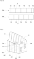
FIG. 1 , a conventional hot stamping die 500 is manufactured by assembling a plurality ofsub-assemblies 502 each having a formingsurface 504. Thesub-assemblies 502 are provided withcooling channels 506 formed in the longitudinal direction of the die 500. Thecooling channels 506 are formed by gun drilling. As a distance from the formingsurface 504 to thecooling channel 506 is shorter, the cooling performance is better. However, since the die 500 has a three-dimensional complicated shape, it is not easy to shorten the distance. -
KR 2013 0076484 A - The present invention is based on the recognition of the related art described above, and provides a hot stamping die apparatus having excellent cooling performance.
- Also, the present invention provides a hot stamping die apparatus capable of uniformly and effectively cooling a forming surface of a die even when a molded product to be manufactured has a complicated shape and thus a forming surface of a die has a complicated shape.
- The problems to be solved by the present invention are not necessarily limited to those mentioned above, and other problems not mentioned herein may be understood by the following description.
- According to the present invention, a hot stamping die apparatus is provided as defined in claim 1.
- Further embodiments are defined in the dependent claims.
- Embodiments of the present invention will be more clearly understood from the following detailed description taken in conjunction with the accompanying drawings in which:
-
FIG. 1 illustrates an example of a conventional hot stamping die; -
FIG. 2 illustrates a hot stamping die according to an embodiment of the present invention; -
FIG. 3 illustrates a die plate according to an embodiment of the present invention; -
FIG. 4 illustrates an example of a sub-assembly including die plates according to an embodiment of the present invention; -
FIG. 5 illustrates a structure of a cooling channel in the sub-assembly according to an embodiment which does not fall into the scope of the protection of the present invention; -
FIG. 6 illustrates a hot stamping die according to another embodiment of the present invention; -
FIGS. 7A and7B illustrate a hot stamping die apparatus according to an embodiment of the present invention; -
FIG. 8 illustrates a sub-assembly according to another embodiment of the present invention; -
FIG. 9 illustrates an example of die plates constituting the sub-assembly as illustrated inFIG. 8 ; -
FIG. 10 illustrates a die plate according to another embodiment of the present invention; -
FIG. 11 illustrates a die plate according to another embodiment of the present invention; and -
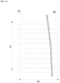
FIG. 12 illustrates a structure of a cooling channel when a sub-assembly is constituted by using the die plates illustrated inFIG. 11 . - Hereinafter, exemplary embodiments of the present invention will be described in detail with reference to the accompanying drawings. In the accompanying drawings, the same or equivalent components or parts are denoted by the same reference numerals as much as possible for convenience of description, and the drawings may be exaggerated and schematically illustrated for a clear understanding and explanation of the features of the invention.
- In the description of the present invention, unless otherwise specified, that a second element is disposed "on" a first element or two elements are "connected" to each other means that two elements are directly contacted or connected to each other, and allows the interrelation between the first and second elements through a third element. Directional expressions such as forward, backward, left and right, or up and down are merely for convenience of description.
- Here, the embodiment of
Fig. 5 does not fall into the scope of the protection of the present invention. It is only to illustrate the present invention. -
FIG. 2 illustrates a die 10 according to an embodiment. Referring toFIG. 2 , the die 10 includes sub-assemblies 11 (11a, 11b, 11c, 11d). An upper surface of each of thesub-assemblies 11 forms a forming surface F for imparting a shape to a part, and a lower portion thereof may be fixed by a clamp C. Each of thesub-assemblies 11 includes a plurality ofplates 20. - Referring to
FIG. 3 , a groove constituting acooling channel 23 is formed on onesurface 21 of theplate 20.Sealing grooves 24 are provided along the groove at both edges in the width direction of the groove. An O-ring (not illustrated) for sealing thecooling channel 23 is inserted into the sealinggrooves 24. Thecooling channel 23 is preferably formed as close as possible to the forming surface F. Since the groove constituting thecooling channel 23 is formed by machining the surface of theplate 20, thecooling channel 23 can be formed as close as possible to the forming surface even if the forming surface F has a complicated shape. Thecooling channel 23 may be formed along the surface of theplate 20, and have inlet 23a andoutlet 23b. - Referring to
FIG. 4 , thesub-assembly 11 is manufactured by making a plurality of plates 20 (20a, 20b, 20c, 20d, 20e) erect and sequentially overlapping the plurality ofplates 20 in a face-to-face manner. A fixing member for assembling theplates 20 may be provided between theplates 20, and the upper surface of each of theplates 20 may form the forming surface F. Grooves corresponding to each other are formed so as to form thecircular cooling channel 23 on the overlapping surfaces between theadjacent plates 20. - The two
plates plates 20 sequentially overlapped inFIG. 4 have only one overlapping surface with theadjacent plates outermost plates cooling channel 23 is formed on only one side thereof. In the remaining threeplates cooling channels 23 are formed on both sides thereof. Thecooling channels 23 may not be formed on bothside surfaces 22 of thesub-assembly 11 in consideration of the assembling convenience between thesub-assemblies 11 and the sealing of thecooling channels 23. Thisside surface 22 is a surface that is in contact with the other sub-assembly. -
FIG. 5 illustrates thecooling channels 23 in thesub-assembly 11. Thesub-assembly 11 is fixed to a base (not illustrated) of the die apparatus, and the base is provided withpassages cooling channels 23 of thesub-assembly 11. The cooling water is supplied through asupply passage 101, flows along thecooling channels 23 provided on the overlapping surfaces between theplates 20, and is then discharged to adischarge passage 102. Theinlet 23a and theoutlet 23b of thecooling channel 23 may be provided on each of the overlapping surfaces between theplates 20. -
FIG. 6 illustrates a die according to another embodiment. Referring toFIG. 6 , foursub-assemblies sub-assemblies channels 23 are not formed on both side surfaces of thesub-assembly 11. Therefore, when the sub-assemblies are arranged in only one direction, the contact portions between the sub-assemblies 11 are regularly arranged to cause deterioration of the cooling performance. -
FIG. 7A illustrates a hot stamping die apparatus according to an embodiment. Referring toFIG. 7A , overlapping surfaces betweensub-assemblies upper die 10a are first overlapping surfaces X (X12, X23, X34, X45). Overlapping surfaces betweensub-assemblies lower die 10b are second overlapping surfaces Y (Y12, Y23, Y34, Y45). In a case where the first overlapping surfaces X and the second overlapping surfaces Y are placed at the same position or on the same line when the die apparatus is closed, the cooling performance in the vicinity of the overlapping surfaces X and Y is poor as compared with the other portions. Since coolingchannels 23 are not formed on both side surfaces of each sub-assembly, the cooling performance in the vicinity of the overlapping surfaces between the assemblies is poor. In addition, when the first overlapping surface X and the second overlapping surface Y are arranged on the same line, the cooling performance in the vicinity of the first and second overlapping surfaces X and Y becomes worse. -
FIG. 7B illustrates a hot stamping die apparatus according to another embodiment. As illustrated inFIG. 7B , the first overlapping surface X and the second overlapping surface Y are not disposed at positions matching each other and are misaligned. As shown in the example ofFIG. 7A , the cooling performance deterioration portions caused by the overlapping surfaces X and Y do not appear at regular intervals. -
FIG. 8 illustrates a sub-assembly 13 according to another embodiment. According to the invention, aninlet 23a of a coolingchannel 23 is provided on one side of the sub-assembly 13, and anoutlet 23b of the coolingchannel 23 is provided on the bottom of thesub-assembly 13. As in the previous embodiment, grooves constituting the coolingchannel 23 are formed on the overlapping surfaces betweenplates 20. The cooling water flows through fourth, third, andsecond plates 20d', 20c', and 20b'. As an example, the cooling water is introduced from theinlet 23a of thefifth plate 20e', flows along the coolingchannel 23 provided on the overlapping surface between the fourth andfifth plates 20d' and 20e', and flows to the coolingchannel 23 provided on the overlapping surface between the third andfourth plates 20c' and 20d'. The second, third, andfourth plates 20b', 20c', and 20d' are provided with through-holes 26 (seeFIG. 9 ) such that a coolingchannel 23 formed on one surface of the plate is connected to a coolingchannel 23 formed on the other surface thereof. -
FIG. 9 illustrates theplates 20 constituting the sub-assembly 13 illustrated inFIG. 8 . Theplates 20 ofFIG. 9 are illustrated so as to explain the structure of thesub-assembly 13 ofFIG. 8 , and theplates 20 ofFIGS. 8 and9 are not necessarily the same as each other. - Referring to
FIG. 9 , the cooling channel is not formed on thefront surface 21a of thefirst plate 20a', and the cooling channel (not illustrated) is formed on the rear surface thereof. Thefront surface 21b of thesecond plate 20b overlaps the rear surface of thefirst plate 20a'. A cooling channel having a shape corresponding to the coolingchannel 23 formed on thefront surface 21b of thesecond plate 20b is formed on the rear surface of thefirst plate 20a. Thesecond plate 20b' is provided with a through-hole 26 such that the cooling water flowing along the coolingchannel 23 formed on thefront surface 21b can be supplied from thethird plate 20c'. The rear surface of thethird plate 20c' overlaps the rear surface of thesecond plate 20b'.Cooling channels 23 corresponding to each other are formed on the rear surfaces of thesecond plate 20b' and thethird plate 20c'. Thethird plate 20c' is also provided with a through-hole 26 such that the cooling water flowing along the coolingchannel 23 formed on the rear surface of thethird plate 20c' can be supplied from thefourth plate 20d'. Thefront surface 21d of thefourth plate 20d' overlaps thefront surface 21c of thethird plate 20c', andcooling channels 23 corresponding to each other are formed on thefront surfaces third plate 20c' and thefourth plate 20d'. Thefourth plate 20d' is also provided with a through-hole 26 such that the cooling water can be supplied to or from a coolingchannel 23 formed on the rear surface of thefourth plate 20d'. - According to the embodiment illustrated in
FIGS. 8 and9 , the cooling water flows through theplates 20 while turning in a left and right direction in a zigzag. For example, referring toFIG. 8 , the cooling water flowing from the right to the left along the coolingchannel 23 formed in the overlapping surface of thethird plate 20c' and thefourth plate 20d' passes through the left through-hole 26 and then flows to the right along the coolingchannel 23 formed in the overlapping surface of thesecond plate 20b' and thethird plate 20c'. Then, again, the cooling water flowing to the right along the coolingchannel 23 formed in the overlapping surface of thesecond plate 20b' and thethird plate 20c' may pass through the right through-hole (not illustrated inFIG. 8 ), flow to the left along the coolingchannel 23 formed in the overlapping surfaces of thefirst plate 20a' and thesecond plate 20b' and then be discharged through theoutlet 23b. In the embodiment illustrated inFIGS. 8 and9 , it is possible to form thecooling channels 23 by a required length at a position required for cooling and also reduce pressure load for supplying the cooling water, as compared with the embodiment illustrated inFIG. 5 . The reduction in the pressure load may alleviate the burden of the sealing of the coolingchannel 23 and the tolerance management in assembling the sub-assemblies 13. - Referring to
FIG. 10 , aprotrusion 35 having a narrow width and a sharply bent portion may be provided on the forming surface F of theplate 30. In this case, a bent portion as indicated byreference numeral 35a may be formed in the coolingchannel 33 such that the coolingchannel 33 is formed as close as possible to the forming surface F. However, the flow of the cooling water in the slightly sharply bentportion 35a is not good and the periphery thereof is not sufficiently cooled.Reference numeral 34 denotes a sealing groove into which an O-ring is inserted. For reference, theprotrusion 35 may be formed in the length direction of the sub-assembly 11 as indicated byreference numeral 25 inFIG. 5 . - Referring to
FIGS. 11 and12 , a portion which is not cooled well like the above-describedprotrusion 35 is shown. According to the invention, asecond cooling channel 36 is provided in the length direction of the sub-assembly, which may pass through theprotrusions 35 of theplates 30 in the length direction of the sub-assembly.Reference numeral 37 denotes a groove into which an O-ring for sealing is inserted. Thesecond cooling channel 36 is disposed between the forming surface F of the corresponding sub-assembly and thefirst cooling channel 33.FIG, 12 corresponds to a view from above the sub-assembly 11 illustrated inFIG. 5 . InFIG. 12 , thefirst cooling channel 33 is indicated by a dashed line, thesecond cooling channel 36 is indicated by a solid line, ℓ represents the length direction of the sub-assembly, and w represents the width direction of the sub-assembly. - A chemical refrigerant may be supplied to the
second cooling channel 36. A refrigerant of a saturated liquid state (or a state close thereto) may be supplied to the inlet of thesecond cooling channel 36, and a refrigerant of a saturated gas state (or a state close thereto) may be discharged to the outlet of thesecond cooling channel 36. The molding surface F is cooled by the evaporation enthalpy or latent heat of the refrigerant passing through thesecond cooling channel 36. Due to this, the refrigerant temperature can be kept equal over the whole of thesecond cooling channel 36. If the refrigerant temperature is kept equal, uniform cooling of the molding surface F is possible. - According to the present invention as described above, the cooling channel can be formed to be close to the forming surface along the bending or shape of the forming surface. Therefore, the cooling performance of the die is improved.
- Also, according to the present invention, the forming surface of the die can be uniformly and effectively cooled even when the molded product has a complicated shape and thus a forming surface of a die has a complicated shape.
- While specific embodiments of the present invention have been illustrated and described, it will be understood by those skilled in the art that changes may be made to those embodiments without departing from the scope of the invention that is defined by the following claims.
Claims (3)
- A hot stamping die apparatus comprising:a first die (10a) having a first forming surface (F); anda second die (10b) having a second forming surface (F) corresponding to the first forming surface (F),wherein each of the first die (10a) and the second die comprises a plurality of sub-assemblies (11, 12, 13) connected to each other, andthe sub-assemblies (11, 12, 13) are constructed by making a plurality of plates erect and sequentially overlapping the plurality of plates (20) in a face-to-face manner, and a first cooling channel (23) is provided by forming grooves corresponding to each other on overlapping surfaces of adjacent plates (20) along the forming surfaces (F),characterized in thatat least one of the sub-assemblies (13) has an inlet (23a) of the first cooling channel (23) on one side of the sub-assembly (13) and an outlet (23b) of the first cooling channel (23) on the bottom of the sub-assembly (13),the first cooling channel (23) of at least one of the sub-assemblies (13) extends in the length direction of the sub-assembly (13) to make a zigzag pattern, and through-holes (26) are provided in the plates of the sub-assembly (13) such that the first cooling channels (23) are connected to each other between adjacent plates, andat least one of the sub-assemblies (11,12,13) is provided with a second cooling channel (36) formed in the length direction of the sub-assembly (11,12,13) such that the second cooling channel (36) passes through the plates, and the second cooling channel (36) is disposed between the forming surface and the first cooling channel (23) of the sub-assembly (11,12,13).
- The hot stamping die apparatus of claim 1, when the first die (10a) and the second die (10b) are closed, first overlapping surfaces (X) between the sub-assemblies (11) constituting the first die (10a) and second overlapping surfaces (Y) between the sub-assemblies (11) constituting the second die (10b) are arranged to be misaligned.
- The hot stamping die apparatus of claim 1, wherein at least one of the first die (10a) and the second die (10b) has a first sub-assembly array in which the plates (20) are arranged in the length direction of the die (10) and a second sub-assembly array in which the plates (20) are arranged in the width direction of the die (10).
Applications Claiming Priority (1)
| Application Number | Priority Date | Filing Date | Title |
|---|---|---|---|
| KR1020170184870A KR102052931B1 (en) | 2017-12-29 | 2017-12-29 | Hot stamping die apparatus |
Publications (2)
| Publication Number | Publication Date |
|---|---|
| EP3505266A1 EP3505266A1 (en) | 2019-07-03 |
| EP3505266B1 true EP3505266B1 (en) | 2024-01-10 |
Family
ID=63363966
Family Applications (1)
| Application Number | Title | Priority Date | Filing Date |
|---|---|---|---|
| EP18190222.2A Active EP3505266B1 (en) | 2017-12-29 | 2018-08-22 | Hot stamping die apparatus |
Country Status (7)
| Country | Link |
|---|---|
| US (1) | US11123783B2 (en) |
| EP (1) | EP3505266B1 (en) |
| JP (1) | JP6647353B2 (en) |
| KR (1) | KR102052931B1 (en) |
| CN (1) | CN109985968B (en) |
| BR (1) | BR102018067801B1 (en) |
| ES (1) | ES2973512T3 (en) |
Families Citing this family (5)
| Publication number | Priority date | Publication date | Assignee | Title |
|---|---|---|---|---|
| JP7280817B2 (en) * | 2019-12-23 | 2023-05-24 | 住友重機械工業株式会社 | Mold and molding equipment |
| US12544821B2 (en) * | 2020-03-26 | 2026-02-10 | Nippon Steel Corporation | Die |
| CN112091067A (en) * | 2020-08-17 | 2020-12-18 | 大连理工大学 | Combined core mold for continuous lamination laying of foil strips |
| CN112338065A (en) * | 2020-11-13 | 2021-02-09 | 湖南晓光汽车模具有限公司 | Multi-water-channel hot stamping die |
| CN114779388B (en) * | 2022-04-28 | 2025-02-07 | 深圳市文生科技有限公司 | A processing technology for optical waveguide lens template |
Family Cites Families (18)
| Publication number | Priority date | Publication date | Assignee | Title |
|---|---|---|---|---|
| SE435527B (en) | 1973-11-06 | 1984-10-01 | Plannja Ab | PROCEDURE FOR PREPARING A PART OF Hardened Steel |
| JPS63278636A (en) * | 1987-05-07 | 1988-11-16 | Aoki Kantaro | Die in die casting apparatus |
| FR2842753B1 (en) * | 2002-07-26 | 2005-03-11 | Financ D Etudes Et De Dev Ind | METHOD FOR PRODUCING A TOOL FOR FORMING A MATERIAL AND TOOL WHICH CAN BE CARRIED OUT BY THIS METHOD |
| DE102004045155A1 (en) * | 2004-09-17 | 2006-03-30 | Benteler Maschinenbau Gmbh | Thermoforming tool |
| DE102007041013A1 (en) * | 2007-08-29 | 2009-03-05 | Linde + Wiemann Gmbh Kg | hot forming tool |
| KR101045839B1 (en) | 2008-10-02 | 2011-07-01 | 주식회사 엠에스 오토텍 | Furnace Equipment for Hot Stamping |
| WO2012160703A1 (en) * | 2011-05-26 | 2012-11-29 | トヨタ自動車株式会社 | Mold for hot press |
| US9227238B2 (en) * | 2011-06-29 | 2016-01-05 | Toyota Jidosha Kabushiki Kaisha | Hot-pressing apparatus |
| KR101326824B1 (en) * | 2011-11-07 | 2013-11-11 | 현대자동차주식회사 | Mold for hot stamping strip masking |
| KR101283983B1 (en) * | 2011-12-28 | 2013-07-09 | 주식회사 엠에스 오토텍 | Modl for hotstamping |
| KR101461887B1 (en) * | 2013-03-15 | 2014-11-13 | 현대자동차 주식회사 | Hot stamping mold |
| DE102013005080B4 (en) * | 2013-03-23 | 2020-12-10 | Volkswagen Aktiengesellschaft | Forming tool for hot forming and / or press hardening of a sheet metal material, as well as a method for producing a coolable forming tool segment |
| KR20140118353A (en) * | 2013-03-29 | 2014-10-08 | 현대제철 주식회사 | Hot stamping forming device |
| JP6093630B2 (en) * | 2013-04-12 | 2017-03-08 | 東プレ株式会社 | Manufacturing method of hot press products |
| CN203356396U (en) * | 2013-07-05 | 2013-12-25 | 上海大学 | Hot stamping die for mechanical performance testing |
| DE102014112244A1 (en) * | 2014-08-26 | 2016-03-03 | Benteler Automobiltechnik Gmbh | Method and press for producing at least partially hardened sheet metal components |
| JP2016147270A (en) * | 2015-02-10 | 2016-08-18 | 株式会社ワイテック | Mold for hot press machine |
| KR101734474B1 (en) * | 2015-09-23 | 2017-05-11 | (주)코링텍 | Hot press forming apparatus and method thereof |
-
2017
- 2017-12-29 KR KR1020170184870A patent/KR102052931B1/en active Active
-
2018
- 2018-08-20 JP JP2018153895A patent/JP6647353B2/en active Active
- 2018-08-21 CN CN201810952450.9A patent/CN109985968B/en active Active
- 2018-08-22 EP EP18190222.2A patent/EP3505266B1/en active Active
- 2018-08-22 ES ES18190222T patent/ES2973512T3/en active Active
- 2018-09-04 BR BR102018067801-9A patent/BR102018067801B1/en active IP Right Grant
- 2018-11-21 US US16/197,474 patent/US11123783B2/en active Active
Also Published As
| Publication number | Publication date |
|---|---|
| US20190201960A1 (en) | 2019-07-04 |
| US11123783B2 (en) | 2021-09-21 |
| JP6647353B2 (en) | 2020-02-14 |
| ES2973512T3 (en) | 2024-06-20 |
| BR102018067801A2 (en) | 2019-07-16 |
| CN109985968A (en) | 2019-07-09 |
| JP2019118957A (en) | 2019-07-22 |
| KR102052931B1 (en) | 2019-12-11 |
| EP3505266A1 (en) | 2019-07-03 |
| CN109985968B (en) | 2021-04-06 |
| KR20190081976A (en) | 2019-07-09 |
| BR102018067801B1 (en) | 2023-03-14 |
Similar Documents
| Publication | Publication Date | Title |
|---|---|---|
| EP3505266A1 (en) | Hot stamping die apparatus | |
| US9061341B2 (en) | Hot-pressing device and method of manufacturing hot-pressed product | |
| EP3258203B1 (en) | Complex pin fin heat exchanger | |
| EP2288454B1 (en) | Press-forming method | |
| US20180021833A1 (en) | Hot press machine, hot press method, and method of manufacturing vehicle body component | |
| EP3484254A1 (en) | Laminated heat sink core | |
| KR101283983B1 (en) | Modl for hotstamping | |
| CN101595361A (en) | Plate type heat exchanger | |
| US20110209861A1 (en) | Method of manufacturing plate heat exchanger and plate heat exchanger | |
| JP5901493B2 (en) | Hot press molding method and mold | |
| KR101876988B1 (en) | Mold for hot stamping | |
| CN102672054B (en) | Thermoforming method and thermoforming mold | |
| US11311928B2 (en) | Hot press machine | |
| JP6357197B2 (en) | Hot pressing method | |
| WO2012160703A1 (en) | Mold for hot press | |
| CN105537414A (en) | Hot stamping die with cooling water channel and manufacturing process thereof | |
| US11185906B2 (en) | Tool with heater for forming part with tailored properties | |
| US11198171B2 (en) | Hot press machine | |
| KR20250105550A (en) | High Frequency Induction Heating Apparatus For Hotstamping | |
| CN205324500U (en) | Hot stamping die with cooling water channel | |
| JP7147586B2 (en) | Hot press processing equipment | |
| WO2019132090A1 (en) | Hot stamping mold apparatus | |
| CN115555478A (en) | Hot stamping die and manufacturing method thereof | |
| KR100510014B1 (en) | Method for making jacket of liquid storage vessel and the structure of the jacket maden therefrom | |
| CN118371932A (en) | Welding device |
Legal Events
| Date | Code | Title | Description |
|---|---|---|---|
| PUAI | Public reference made under article 153(3) epc to a published international application that has entered the european phase |
Free format text: ORIGINAL CODE: 0009012 |
|
| STAA | Information on the status of an ep patent application or granted ep patent |
Free format text: STATUS: REQUEST FOR EXAMINATION WAS MADE |
|
| 17P | Request for examination filed |
Effective date: 20180822 |
|
| AK | Designated contracting states |
Kind code of ref document: A1 Designated state(s): AL AT BE BG CH CY CZ DE DK EE ES FI FR GB GR HR HU IE IS IT LI LT LU LV MC MK MT NL NO PL PT RO RS SE SI SK SM TR |
|
| AX | Request for extension of the european patent |
Extension state: BA ME |
|
| RAP1 | Party data changed (applicant data changed or rights of an application transferred) |
Owner name: MS AUTOTECH CO., LTD. Owner name: MYUNGSHIN INDUSTRY CO., LTD. |
|
| STAA | Information on the status of an ep patent application or granted ep patent |
Free format text: STATUS: EXAMINATION IS IN PROGRESS |
|
| 17Q | First examination report despatched |
Effective date: 20210826 |
|
| GRAP | Despatch of communication of intention to grant a patent |
Free format text: ORIGINAL CODE: EPIDOSNIGR1 |
|
| STAA | Information on the status of an ep patent application or granted ep patent |
Free format text: STATUS: GRANT OF PATENT IS INTENDED |
|
| GRAS | Grant fee paid |
Free format text: ORIGINAL CODE: EPIDOSNIGR3 |
|
| INTG | Intention to grant announced |
Effective date: 20231103 |
|
| GRAA | (expected) grant |
Free format text: ORIGINAL CODE: 0009210 |
|
| STAA | Information on the status of an ep patent application or granted ep patent |
Free format text: STATUS: THE PATENT HAS BEEN GRANTED |
|
| AK | Designated contracting states |
Kind code of ref document: B1 Designated state(s): AL AT BE BG CH CY CZ DE DK EE ES FI FR GB GR HR HU IE IS IT LI LT LU LV MC MK MT NL NO PL PT RO RS SE SI SK SM TR |
|
| REG | Reference to a national code |
Ref country code: GB Ref legal event code: FG4D |
|
| REG | Reference to a national code |
Ref country code: CH Ref legal event code: EP |
|
| REG | Reference to a national code |
Ref country code: DE Ref legal event code: R096 Ref document number: 602018063898 Country of ref document: DE |
|
| REG | Reference to a national code |
Ref country code: IE Ref legal event code: FG4D |
|
| REG | Reference to a national code |
Ref country code: LT Ref legal event code: MG9D |
|
| REG | Reference to a national code |
Ref country code: NL Ref legal event code: MP Effective date: 20240110 |
|
| REG | Reference to a national code |
Ref country code: AT Ref legal event code: MK05 Ref document number: 1648511 Country of ref document: AT Kind code of ref document: T Effective date: 20240110 |
|
| PG25 | Lapsed in a contracting state [announced via postgrant information from national office to epo] |
Ref country code: NL Free format text: LAPSE BECAUSE OF FAILURE TO SUBMIT A TRANSLATION OF THE DESCRIPTION OR TO PAY THE FEE WITHIN THE PRESCRIBED TIME-LIMIT Effective date: 20240110 |
|
| PG25 | Lapsed in a contracting state [announced via postgrant information from national office to epo] |
Ref country code: NL Free format text: LAPSE BECAUSE OF FAILURE TO SUBMIT A TRANSLATION OF THE DESCRIPTION OR TO PAY THE FEE WITHIN THE PRESCRIBED TIME-LIMIT Effective date: 20240110 |
|
| PG25 | Lapsed in a contracting state [announced via postgrant information from national office to epo] |
Ref country code: IS Free format text: LAPSE BECAUSE OF FAILURE TO SUBMIT A TRANSLATION OF THE DESCRIPTION OR TO PAY THE FEE WITHIN THE PRESCRIBED TIME-LIMIT Effective date: 20240510 |
|
| PG25 | Lapsed in a contracting state [announced via postgrant information from national office to epo] |
Ref country code: LT Free format text: LAPSE BECAUSE OF FAILURE TO SUBMIT A TRANSLATION OF THE DESCRIPTION OR TO PAY THE FEE WITHIN THE PRESCRIBED TIME-LIMIT Effective date: 20240110 |
|
| PG25 | Lapsed in a contracting state [announced via postgrant information from national office to epo] |
Ref country code: GR Free format text: LAPSE BECAUSE OF FAILURE TO SUBMIT A TRANSLATION OF THE DESCRIPTION OR TO PAY THE FEE WITHIN THE PRESCRIBED TIME-LIMIT Effective date: 20240411 |
|
| PG25 | Lapsed in a contracting state [announced via postgrant information from national office to epo] |
Ref country code: HR Free format text: LAPSE BECAUSE OF FAILURE TO SUBMIT A TRANSLATION OF THE DESCRIPTION OR TO PAY THE FEE WITHIN THE PRESCRIBED TIME-LIMIT Effective date: 20240110 Ref country code: RS Free format text: LAPSE BECAUSE OF FAILURE TO SUBMIT A TRANSLATION OF THE DESCRIPTION OR TO PAY THE FEE WITHIN THE PRESCRIBED TIME-LIMIT Effective date: 20240410 |
|
| PG25 | Lapsed in a contracting state [announced via postgrant information from national office to epo] |
Ref country code: AT Free format text: LAPSE BECAUSE OF FAILURE TO SUBMIT A TRANSLATION OF THE DESCRIPTION OR TO PAY THE FEE WITHIN THE PRESCRIBED TIME-LIMIT Effective date: 20240110 |
|
| PG25 | Lapsed in a contracting state [announced via postgrant information from national office to epo] |
Ref country code: RS Free format text: LAPSE BECAUSE OF FAILURE TO SUBMIT A TRANSLATION OF THE DESCRIPTION OR TO PAY THE FEE WITHIN THE PRESCRIBED TIME-LIMIT Effective date: 20240410 Ref country code: NO Free format text: LAPSE BECAUSE OF FAILURE TO SUBMIT A TRANSLATION OF THE DESCRIPTION OR TO PAY THE FEE WITHIN THE PRESCRIBED TIME-LIMIT Effective date: 20240410 Ref country code: LT Free format text: LAPSE BECAUSE OF FAILURE TO SUBMIT A TRANSLATION OF THE DESCRIPTION OR TO PAY THE FEE WITHIN THE PRESCRIBED TIME-LIMIT Effective date: 20240110 Ref country code: IS Free format text: LAPSE BECAUSE OF FAILURE TO SUBMIT A TRANSLATION OF THE DESCRIPTION OR TO PAY THE FEE WITHIN THE PRESCRIBED TIME-LIMIT Effective date: 20240510 Ref country code: HR Free format text: LAPSE BECAUSE OF FAILURE TO SUBMIT A TRANSLATION OF THE DESCRIPTION OR TO PAY THE FEE WITHIN THE PRESCRIBED TIME-LIMIT Effective date: 20240110 Ref country code: GR Free format text: LAPSE BECAUSE OF FAILURE TO SUBMIT A TRANSLATION OF THE DESCRIPTION OR TO PAY THE FEE WITHIN THE PRESCRIBED TIME-LIMIT Effective date: 20240411 Ref country code: BG Free format text: LAPSE BECAUSE OF FAILURE TO SUBMIT A TRANSLATION OF THE DESCRIPTION OR TO PAY THE FEE WITHIN THE PRESCRIBED TIME-LIMIT Effective date: 20240110 Ref country code: AT Free format text: LAPSE BECAUSE OF FAILURE TO SUBMIT A TRANSLATION OF THE DESCRIPTION OR TO PAY THE FEE WITHIN THE PRESCRIBED TIME-LIMIT Effective date: 20240110 |
|
| PG25 | Lapsed in a contracting state [announced via postgrant information from national office to epo] |
Ref country code: PT Free format text: LAPSE BECAUSE OF FAILURE TO SUBMIT A TRANSLATION OF THE DESCRIPTION OR TO PAY THE FEE WITHIN THE PRESCRIBED TIME-LIMIT Effective date: 20240510 Ref country code: PL Free format text: LAPSE BECAUSE OF FAILURE TO SUBMIT A TRANSLATION OF THE DESCRIPTION OR TO PAY THE FEE WITHIN THE PRESCRIBED TIME-LIMIT Effective date: 20240110 |
|
| PG25 | Lapsed in a contracting state [announced via postgrant information from national office to epo] |
Ref country code: SE Free format text: LAPSE BECAUSE OF FAILURE TO SUBMIT A TRANSLATION OF THE DESCRIPTION OR TO PAY THE FEE WITHIN THE PRESCRIBED TIME-LIMIT Effective date: 20240110 Ref country code: PT Free format text: LAPSE BECAUSE OF FAILURE TO SUBMIT A TRANSLATION OF THE DESCRIPTION OR TO PAY THE FEE WITHIN THE PRESCRIBED TIME-LIMIT Effective date: 20240510 Ref country code: PL Free format text: LAPSE BECAUSE OF FAILURE TO SUBMIT A TRANSLATION OF THE DESCRIPTION OR TO PAY THE FEE WITHIN THE PRESCRIBED TIME-LIMIT Effective date: 20240110 Ref country code: LV Free format text: LAPSE BECAUSE OF FAILURE TO SUBMIT A TRANSLATION OF THE DESCRIPTION OR TO PAY THE FEE WITHIN THE PRESCRIBED TIME-LIMIT Effective date: 20240110 |
|
| PG25 | Lapsed in a contracting state [announced via postgrant information from national office to epo] |
Ref country code: DK Free format text: LAPSE BECAUSE OF FAILURE TO SUBMIT A TRANSLATION OF THE DESCRIPTION OR TO PAY THE FEE WITHIN THE PRESCRIBED TIME-LIMIT Effective date: 20240110 |
|
| REG | Reference to a national code |
Ref country code: DE Ref legal event code: R097 Ref document number: 602018063898 Country of ref document: DE |
|
| PG25 | Lapsed in a contracting state [announced via postgrant information from national office to epo] |
Ref country code: SM Free format text: LAPSE BECAUSE OF FAILURE TO SUBMIT A TRANSLATION OF THE DESCRIPTION OR TO PAY THE FEE WITHIN THE PRESCRIBED TIME-LIMIT Effective date: 20240110 |
|
| PG25 | Lapsed in a contracting state [announced via postgrant information from national office to epo] |
Ref country code: CZ Free format text: LAPSE BECAUSE OF FAILURE TO SUBMIT A TRANSLATION OF THE DESCRIPTION OR TO PAY THE FEE WITHIN THE PRESCRIBED TIME-LIMIT Effective date: 20240110 Ref country code: EE Free format text: LAPSE BECAUSE OF FAILURE TO SUBMIT A TRANSLATION OF THE DESCRIPTION OR TO PAY THE FEE WITHIN THE PRESCRIBED TIME-LIMIT Effective date: 20240110 |
|
| PG25 | Lapsed in a contracting state [announced via postgrant information from national office to epo] |
Ref country code: SK Free format text: LAPSE BECAUSE OF FAILURE TO SUBMIT A TRANSLATION OF THE DESCRIPTION OR TO PAY THE FEE WITHIN THE PRESCRIBED TIME-LIMIT Effective date: 20240110 |
|
| PG25 | Lapsed in a contracting state [announced via postgrant information from national office to epo] |
Ref country code: SM Free format text: LAPSE BECAUSE OF FAILURE TO SUBMIT A TRANSLATION OF THE DESCRIPTION OR TO PAY THE FEE WITHIN THE PRESCRIBED TIME-LIMIT Effective date: 20240110 Ref country code: SK Free format text: LAPSE BECAUSE OF FAILURE TO SUBMIT A TRANSLATION OF THE DESCRIPTION OR TO PAY THE FEE WITHIN THE PRESCRIBED TIME-LIMIT Effective date: 20240110 Ref country code: RO Free format text: LAPSE BECAUSE OF FAILURE TO SUBMIT A TRANSLATION OF THE DESCRIPTION OR TO PAY THE FEE WITHIN THE PRESCRIBED TIME-LIMIT Effective date: 20240110 Ref country code: EE Free format text: LAPSE BECAUSE OF FAILURE TO SUBMIT A TRANSLATION OF THE DESCRIPTION OR TO PAY THE FEE WITHIN THE PRESCRIBED TIME-LIMIT Effective date: 20240110 Ref country code: DK Free format text: LAPSE BECAUSE OF FAILURE TO SUBMIT A TRANSLATION OF THE DESCRIPTION OR TO PAY THE FEE WITHIN THE PRESCRIBED TIME-LIMIT Effective date: 20240110 Ref country code: CZ Free format text: LAPSE BECAUSE OF FAILURE TO SUBMIT A TRANSLATION OF THE DESCRIPTION OR TO PAY THE FEE WITHIN THE PRESCRIBED TIME-LIMIT Effective date: 20240110 |
|
| PLBE | No opposition filed within time limit |
Free format text: ORIGINAL CODE: 0009261 |
|
| STAA | Information on the status of an ep patent application or granted ep patent |
Free format text: STATUS: NO OPPOSITION FILED WITHIN TIME LIMIT |
|
| PG25 | Lapsed in a contracting state [announced via postgrant information from national office to epo] |
Ref country code: IT Free format text: LAPSE BECAUSE OF FAILURE TO SUBMIT A TRANSLATION OF THE DESCRIPTION OR TO PAY THE FEE WITHIN THE PRESCRIBED TIME-LIMIT Effective date: 20240110 |
|
| 26N | No opposition filed |
Effective date: 20241011 |
|
| PG25 | Lapsed in a contracting state [announced via postgrant information from national office to epo] |
Ref country code: IT Free format text: LAPSE BECAUSE OF FAILURE TO SUBMIT A TRANSLATION OF THE DESCRIPTION OR TO PAY THE FEE WITHIN THE PRESCRIBED TIME-LIMIT Effective date: 20240110 |
|
| REG | Reference to a national code |
Ref country code: CH Ref legal event code: PL |
|
| PG25 | Lapsed in a contracting state [announced via postgrant information from national office to epo] |
Ref country code: LU Free format text: LAPSE BECAUSE OF NON-PAYMENT OF DUE FEES Effective date: 20240822 |
|
| GBPC | Gb: european patent ceased through non-payment of renewal fee |
Effective date: 20240822 |
|
| PG25 | Lapsed in a contracting state [announced via postgrant information from national office to epo] |
Ref country code: SI Free format text: LAPSE BECAUSE OF FAILURE TO SUBMIT A TRANSLATION OF THE DESCRIPTION OR TO PAY THE FEE WITHIN THE PRESCRIBED TIME-LIMIT Effective date: 20240110 Ref country code: MC Free format text: LAPSE BECAUSE OF FAILURE TO SUBMIT A TRANSLATION OF THE DESCRIPTION OR TO PAY THE FEE WITHIN THE PRESCRIBED TIME-LIMIT Effective date: 20240110 Ref country code: CH Free format text: LAPSE BECAUSE OF NON-PAYMENT OF DUE FEES Effective date: 20240831 |
|
| REG | Reference to a national code |
Ref country code: BE Ref legal event code: MM Effective date: 20240831 |
|
| PG25 | Lapsed in a contracting state [announced via postgrant information from national office to epo] |
Ref country code: GB Free format text: LAPSE BECAUSE OF NON-PAYMENT OF DUE FEES Effective date: 20240822 |
|
| PG25 | Lapsed in a contracting state [announced via postgrant information from national office to epo] |
Ref country code: BE Free format text: LAPSE BECAUSE OF NON-PAYMENT OF DUE FEES Effective date: 20240831 |
|
| PG25 | Lapsed in a contracting state [announced via postgrant information from national office to epo] |
Ref country code: FR Free format text: LAPSE BECAUSE OF NON-PAYMENT OF DUE FEES Effective date: 20240831 |
|
| PG25 | Lapsed in a contracting state [announced via postgrant information from national office to epo] |
Ref country code: IE Free format text: LAPSE BECAUSE OF NON-PAYMENT OF DUE FEES Effective date: 20240822 |
|
| PG25 | Lapsed in a contracting state [announced via postgrant information from national office to epo] |
Ref country code: FI Free format text: LAPSE BECAUSE OF FAILURE TO SUBMIT A TRANSLATION OF THE DESCRIPTION OR TO PAY THE FEE WITHIN THE PRESCRIBED TIME-LIMIT Effective date: 20240110 |
|
| PGFP | Annual fee paid to national office [announced via postgrant information from national office to epo] |
Ref country code: ES Payment date: 20250917 Year of fee payment: 8 |
|
| PGFP | Annual fee paid to national office [announced via postgrant information from national office to epo] |
Ref country code: DE Payment date: 20250825 Year of fee payment: 8 |
|
| PG25 | Lapsed in a contracting state [announced via postgrant information from national office to epo] |
Ref country code: CY Free format text: LAPSE BECAUSE OF FAILURE TO SUBMIT A TRANSLATION OF THE DESCRIPTION OR TO PAY THE FEE WITHIN THE PRESCRIBED TIME-LIMIT; INVALID AB INITIO Effective date: 20180822 |
|
| PG25 | Lapsed in a contracting state [announced via postgrant information from national office to epo] |
Ref country code: HU Free format text: LAPSE BECAUSE OF FAILURE TO SUBMIT A TRANSLATION OF THE DESCRIPTION OR TO PAY THE FEE WITHIN THE PRESCRIBED TIME-LIMIT; INVALID AB INITIO Effective date: 20180822 |