EP3505126A1 - Surgical evacuation system with a communication circuit for communication between a filter and a smoke evacuation device - Google Patents
Surgical evacuation system with a communication circuit for communication between a filter and a smoke evacuation device Download PDFInfo
- Publication number
- EP3505126A1 EP3505126A1 EP18275262.6A EP18275262A EP3505126A1 EP 3505126 A1 EP3505126 A1 EP 3505126A1 EP 18275262 A EP18275262 A EP 18275262A EP 3505126 A1 EP3505126 A1 EP 3505126A1
- Authority
- EP
- European Patent Office
- Prior art keywords
- filter
- surgical
- fluid
- smoke
- communication
- Prior art date
- Legal status (The legal status is an assumption and is not a legal conclusion. Google has not performed a legal analysis and makes no representation as to the accuracy of the status listed.)
- Granted
Links
- 238000004891 communication Methods 0.000 title claims abstract description 269
- 239000000779 smoke Substances 0.000 title claims abstract description 232
- 239000012530 fluid Substances 0.000 claims abstract description 458
- 239000003610 charcoal Substances 0.000 claims abstract description 24
- 238000000034 method Methods 0.000 claims description 136
- 230000015654 memory Effects 0.000 claims description 89
- 230000008569 process Effects 0.000 claims description 24
- 230000000670 limiting effect Effects 0.000 claims description 6
- 210000001519 tissue Anatomy 0.000 description 156
- 238000006073 displacement reaction Methods 0.000 description 75
- 239000012636 effector Substances 0.000 description 74
- 238000010304 firing Methods 0.000 description 65
- 238000001356 surgical procedure Methods 0.000 description 51
- 239000002245 particle Substances 0.000 description 47
- 230000002452 interceptive effect Effects 0.000 description 39
- 238000003384 imaging method Methods 0.000 description 37
- 238000001514 detection method Methods 0.000 description 36
- 238000005520 cutting process Methods 0.000 description 35
- 238000012545 processing Methods 0.000 description 35
- 230000006870 function Effects 0.000 description 34
- 239000007789 gas Substances 0.000 description 33
- 238000004422 calculation algorithm Methods 0.000 description 31
- 238000003032 molecular docking Methods 0.000 description 28
- 238000003860 storage Methods 0.000 description 27
- 239000003570 air Substances 0.000 description 26
- 230000033001 locomotion Effects 0.000 description 25
- 230000004044 response Effects 0.000 description 24
- 230000007246 mechanism Effects 0.000 description 23
- 238000011144 upstream manufacturing Methods 0.000 description 23
- 238000012800 visualization Methods 0.000 description 21
- 238000010586 diagram Methods 0.000 description 20
- 230000005540 biological transmission Effects 0.000 description 19
- 238000001914 filtration Methods 0.000 description 18
- 230000006835 compression Effects 0.000 description 17
- 238000007906 compression Methods 0.000 description 17
- 238000013519 translation Methods 0.000 description 17
- 230000002262 irrigation Effects 0.000 description 16
- 238000003973 irrigation Methods 0.000 description 16
- OKTJSMMVPCPJKN-UHFFFAOYSA-N Carbon Chemical compound [C] OKTJSMMVPCPJKN-UHFFFAOYSA-N 0.000 description 15
- 238000002059 diagnostic imaging Methods 0.000 description 15
- 239000007788 liquid Substances 0.000 description 15
- 239000000463 material Substances 0.000 description 15
- 239000000126 substance Substances 0.000 description 15
- 230000008901 benefit Effects 0.000 description 14
- 230000003287 optical effect Effects 0.000 description 14
- 239000013618 particulate matter Substances 0.000 description 14
- 239000003990 capacitor Substances 0.000 description 13
- 238000001228 spectrum Methods 0.000 description 12
- 229910052799 carbon Inorganic materials 0.000 description 11
- 239000000443 aerosol Substances 0.000 description 10
- 230000001413 cellular effect Effects 0.000 description 10
- 230000015271 coagulation Effects 0.000 description 10
- 238000005345 coagulation Methods 0.000 description 10
- 238000013500 data storage Methods 0.000 description 10
- 230000000694 effects Effects 0.000 description 10
- 230000004048 modification Effects 0.000 description 10
- 238000012986 modification Methods 0.000 description 10
- 230000005355 Hall effect Effects 0.000 description 9
- 230000004913 activation Effects 0.000 description 9
- 230000003044 adaptive effect Effects 0.000 description 9
- 230000006378 damage Effects 0.000 description 9
- 238000005516 engineering process Methods 0.000 description 9
- 238000002955 isolation Methods 0.000 description 9
- 238000007726 management method Methods 0.000 description 9
- 230000002093 peripheral effect Effects 0.000 description 9
- 230000003134 recirculating effect Effects 0.000 description 9
- 239000000523 sample Substances 0.000 description 9
- 230000007704 transition Effects 0.000 description 9
- 210000004204 blood vessel Anatomy 0.000 description 8
- 210000004072 lung Anatomy 0.000 description 8
- 238000005259 measurement Methods 0.000 description 8
- 238000007789 sealing Methods 0.000 description 8
- 238000013538 segmental resection Methods 0.000 description 8
- 239000002594 sorbent Substances 0.000 description 8
- 238000012546 transfer Methods 0.000 description 8
- -1 creosols Chemical compound 0.000 description 7
- 230000003993 interaction Effects 0.000 description 7
- 238000012806 monitoring device Methods 0.000 description 7
- 208000025247 virus-associated trichodysplasia spinulosa Diseases 0.000 description 7
- 230000000903 blocking effect Effects 0.000 description 6
- 210000004027 cell Anatomy 0.000 description 6
- 230000008878 coupling Effects 0.000 description 6
- 238000010168 coupling process Methods 0.000 description 6
- 238000005859 coupling reaction Methods 0.000 description 6
- 230000002441 reversible effect Effects 0.000 description 6
- 238000005070 sampling Methods 0.000 description 6
- 238000012795 verification Methods 0.000 description 6
- 230000008859 change Effects 0.000 description 5
- 230000003750 conditioning effect Effects 0.000 description 5
- 238000013461 design Methods 0.000 description 5
- 238000004520 electroporation Methods 0.000 description 5
- 238000000605 extraction Methods 0.000 description 5
- 238000010438 heat treatment Methods 0.000 description 5
- 230000001976 improved effect Effects 0.000 description 5
- 230000002427 irreversible effect Effects 0.000 description 5
- SYHGEUNFJIGTRX-UHFFFAOYSA-N methylenedioxypyrovalerone Chemical compound C=1C=C2OCOC2=CC=1C(=O)C(CCC)N1CCCC1 SYHGEUNFJIGTRX-UHFFFAOYSA-N 0.000 description 5
- 238000012544 monitoring process Methods 0.000 description 5
- 230000009467 reduction Effects 0.000 description 5
- 210000000115 thoracic cavity Anatomy 0.000 description 5
- XLYOFNOQVPJJNP-UHFFFAOYSA-N water Substances O XLYOFNOQVPJJNP-UHFFFAOYSA-N 0.000 description 5
- 238000004804 winding Methods 0.000 description 5
- 206010002091 Anaesthesia Diseases 0.000 description 4
- 241000555745 Sciuridae Species 0.000 description 4
- 230000009471 action Effects 0.000 description 4
- 230000037005 anaesthesia Effects 0.000 description 4
- 238000004364 calculation method Methods 0.000 description 4
- 238000004590 computer program Methods 0.000 description 4
- 230000007423 decrease Effects 0.000 description 4
- 238000002224 dissection Methods 0.000 description 4
- 230000009977 dual effect Effects 0.000 description 4
- 239000000835 fiber Substances 0.000 description 4
- 230000001939 inductive effect Effects 0.000 description 4
- 230000017074 necrotic cell death Effects 0.000 description 4
- 230000002829 reductive effect Effects 0.000 description 4
- 230000001360 synchronised effect Effects 0.000 description 4
- 238000011282 treatment Methods 0.000 description 4
- 238000001429 visible spectrum Methods 0.000 description 4
- WEVYAHXRMPXWCK-UHFFFAOYSA-N Acetonitrile Chemical compound CC#N WEVYAHXRMPXWCK-UHFFFAOYSA-N 0.000 description 3
- UHOVQNZJYSORNB-UHFFFAOYSA-N Benzene Chemical compound C1=CC=CC=C1 UHOVQNZJYSORNB-UHFFFAOYSA-N 0.000 description 3
- QQONPFPTGQHPMA-UHFFFAOYSA-N Propene Chemical compound CC=C QQONPFPTGQHPMA-UHFFFAOYSA-N 0.000 description 3
- YXFVVABEGXRONW-UHFFFAOYSA-N Toluene Chemical compound CC1=CC=CC=C1 YXFVVABEGXRONW-UHFFFAOYSA-N 0.000 description 3
- 230000004931 aggregating effect Effects 0.000 description 3
- 238000004458 analytical method Methods 0.000 description 3
- 210000003484 anatomy Anatomy 0.000 description 3
- 230000009286 beneficial effect Effects 0.000 description 3
- 239000008280 blood Substances 0.000 description 3
- 210000004369 blood Anatomy 0.000 description 3
- 239000003795 chemical substances by application Substances 0.000 description 3
- 239000004020 conductor Substances 0.000 description 3
- 238000010276 construction Methods 0.000 description 3
- 238000011109 contamination Methods 0.000 description 3
- 238000009826 distribution Methods 0.000 description 3
- 230000005670 electromagnetic radiation Effects 0.000 description 3
- 239000003344 environmental pollutant Substances 0.000 description 3
- 239000011152 fibreglass Substances 0.000 description 3
- 230000014509 gene expression Effects 0.000 description 3
- 238000005286 illumination Methods 0.000 description 3
- PWPJGUXAGUPAHP-UHFFFAOYSA-N lufenuron Chemical compound C1=C(Cl)C(OC(F)(F)C(C(F)(F)F)F)=CC(Cl)=C1NC(=O)NC(=O)C1=C(F)C=CC=C1F PWPJGUXAGUPAHP-UHFFFAOYSA-N 0.000 description 3
- 239000012528 membrane Substances 0.000 description 3
- 210000005036 nerve Anatomy 0.000 description 3
- 235000019645 odor Nutrition 0.000 description 3
- 230000035515 penetration Effects 0.000 description 3
- 231100000719 pollutant Toxicity 0.000 description 3
- 229920000728 polyester Polymers 0.000 description 3
- 230000001954 sterilising effect Effects 0.000 description 3
- 238000004659 sterilization and disinfection Methods 0.000 description 3
- 230000000451 tissue damage Effects 0.000 description 3
- 231100000827 tissue damage Toxicity 0.000 description 3
- HGINCPLSRVDWNT-UHFFFAOYSA-N Acrolein Chemical compound C=CC=O HGINCPLSRVDWNT-UHFFFAOYSA-N 0.000 description 2
- KAKZBPTYRLMSJV-UHFFFAOYSA-N Butadiene Chemical compound C=CC=C KAKZBPTYRLMSJV-UHFFFAOYSA-N 0.000 description 2
- UGFAIRIUMAVXCW-UHFFFAOYSA-N Carbon monoxide Chemical compound [O+]#[C-] UGFAIRIUMAVXCW-UHFFFAOYSA-N 0.000 description 2
- VQTUBCCKSQIDNK-UHFFFAOYSA-N Isobutene Chemical compound CC(C)=C VQTUBCCKSQIDNK-UHFFFAOYSA-N 0.000 description 2
- HBBGRARXTFLTSG-UHFFFAOYSA-N Lithium ion Chemical compound [Li+] HBBGRARXTFLTSG-UHFFFAOYSA-N 0.000 description 2
- ISWSIDIOOBJBQZ-UHFFFAOYSA-N Phenol Chemical compound OC1=CC=CC=C1 ISWSIDIOOBJBQZ-UHFFFAOYSA-N 0.000 description 2
- 208000035965 Postoperative Complications Diseases 0.000 description 2
- KAESVJOAVNADME-UHFFFAOYSA-N Pyrrole Chemical compound C=1C=CNC=1 KAESVJOAVNADME-UHFFFAOYSA-N 0.000 description 2
- FAPWRFPIFSIZLT-UHFFFAOYSA-M Sodium chloride Chemical compound [Na+].[Cl-] FAPWRFPIFSIZLT-UHFFFAOYSA-M 0.000 description 2
- PPBRXRYQALVLMV-UHFFFAOYSA-N Styrene Chemical compound C=CC1=CC=CC=C1 PPBRXRYQALVLMV-UHFFFAOYSA-N 0.000 description 2
- 239000012080 ambient air Substances 0.000 description 2
- 230000006399 behavior Effects 0.000 description 2
- 230000002457 bidirectional effect Effects 0.000 description 2
- 229910002091 carbon monoxide Inorganic materials 0.000 description 2
- 231100000357 carcinogen Toxicity 0.000 description 2
- 239000003183 carcinogenic agent Substances 0.000 description 2
- 238000000701 chemical imaging Methods 0.000 description 2
- 239000003638 chemical reducing agent Substances 0.000 description 2
- 210000000078 claw Anatomy 0.000 description 2
- 239000000356 contaminant Substances 0.000 description 2
- 230000003247 decreasing effect Effects 0.000 description 2
- 230000007812 deficiency Effects 0.000 description 2
- 238000002405 diagnostic procedure Methods 0.000 description 2
- 238000012976 endoscopic surgical procedure Methods 0.000 description 2
- 239000000284 extract Substances 0.000 description 2
- 210000000416 exudates and transudate Anatomy 0.000 description 2
- 230000005669 field effect Effects 0.000 description 2
- 230000005484 gravity Effects 0.000 description 2
- 230000035876 healing Effects 0.000 description 2
- 230000002439 hemostatic effect Effects 0.000 description 2
- LELOWRISYMNNSU-UHFFFAOYSA-N hydrogen cyanide Chemical compound N#C LELOWRISYMNNSU-UHFFFAOYSA-N 0.000 description 2
- 229910001416 lithium ion Inorganic materials 0.000 description 2
- 230000007774 longterm Effects 0.000 description 2
- 210000002751 lymph Anatomy 0.000 description 2
- 229910044991 metal oxide Inorganic materials 0.000 description 2
- 150000004706 metal oxides Chemical class 0.000 description 2
- VNWKTOKETHGBQD-UHFFFAOYSA-N methane Chemical compound C VNWKTOKETHGBQD-UHFFFAOYSA-N 0.000 description 2
- 239000000203 mixture Substances 0.000 description 2
- 210000003205 muscle Anatomy 0.000 description 2
- 230000036961 partial effect Effects 0.000 description 2
- 229920001343 polytetrafluoroethylene Polymers 0.000 description 2
- 239000004810 polytetrafluoroethylene Substances 0.000 description 2
- 230000002980 postoperative effect Effects 0.000 description 2
- 238000012913 prioritisation Methods 0.000 description 2
- 238000011084 recovery Methods 0.000 description 2
- 230000001172 regenerating effect Effects 0.000 description 2
- 239000004065 semiconductor Substances 0.000 description 2
- 239000011780 sodium chloride Substances 0.000 description 2
- 230000000638 stimulation Effects 0.000 description 2
- 238000006467 substitution reaction Methods 0.000 description 2
- 238000012360 testing method Methods 0.000 description 2
- 230000001225 therapeutic effect Effects 0.000 description 2
- 239000003053 toxin Substances 0.000 description 2
- 231100000765 toxin Toxicity 0.000 description 2
- 108700012359 toxins Proteins 0.000 description 2
- 238000002604 ultrasonography Methods 0.000 description 2
- VXNZUUAINFGPBY-UHFFFAOYSA-N 1-Butene Chemical compound CCC=C VXNZUUAINFGPBY-UHFFFAOYSA-N 0.000 description 1
- 206010000060 Abdominal distension Diseases 0.000 description 1
- NLHHRLWOUZZQLW-UHFFFAOYSA-N Acrylonitrile Chemical compound C=CC#N NLHHRLWOUZZQLW-UHFFFAOYSA-N 0.000 description 1
- 241000238366 Cephalopoda Species 0.000 description 1
- 235000013162 Cocos nucifera Nutrition 0.000 description 1
- 244000060011 Cocos nucifera Species 0.000 description 1
- 102000008186 Collagen Human genes 0.000 description 1
- 108010035532 Collagen Proteins 0.000 description 1
- RYGMFSIKBFXOCR-UHFFFAOYSA-N Copper Chemical compound [Cu] RYGMFSIKBFXOCR-UHFFFAOYSA-N 0.000 description 1
- QPLDLSVMHZLSFG-UHFFFAOYSA-N Copper oxide Chemical compound [Cu]=O QPLDLSVMHZLSFG-UHFFFAOYSA-N 0.000 description 1
- 239000005751 Copper oxide Substances 0.000 description 1
- 206010051814 Eschar Diseases 0.000 description 1
- OTMSDBZUPAUEDD-UHFFFAOYSA-N Ethane Chemical compound CC OTMSDBZUPAUEDD-UHFFFAOYSA-N 0.000 description 1
- VGGSQFUCUMXWEO-UHFFFAOYSA-N Ethene Chemical compound C=C VGGSQFUCUMXWEO-UHFFFAOYSA-N 0.000 description 1
- 239000005977 Ethylene Substances 0.000 description 1
- IAYPIBMASNFSPL-UHFFFAOYSA-N Ethylene oxide Chemical compound C1CO1 IAYPIBMASNFSPL-UHFFFAOYSA-N 0.000 description 1
- 206010015946 Eye irritation Diseases 0.000 description 1
- CTQNGGLPUBDAKN-UHFFFAOYSA-N O-Xylene Chemical compound CC1=CC=CC=C1C CTQNGGLPUBDAKN-UHFFFAOYSA-N 0.000 description 1
- CBENFWSGALASAD-UHFFFAOYSA-N Ozone Chemical compound [O-][O+]=O CBENFWSGALASAD-UHFFFAOYSA-N 0.000 description 1
- 206010038731 Respiratory tract irritation Diseases 0.000 description 1
- 241000700605 Viruses Species 0.000 description 1
- 210000001015 abdomen Anatomy 0.000 description 1
- 238000010521 absorption reaction Methods 0.000 description 1
- 230000001154 acute effect Effects 0.000 description 1
- 230000002776 aggregation Effects 0.000 description 1
- 238000004220 aggregation Methods 0.000 description 1
- 238000013019 agitation Methods 0.000 description 1
- 150000004996 alkyl benzenes Chemical class 0.000 description 1
- HSFWRNGVRCDJHI-UHFFFAOYSA-N alpha-acetylene Natural products C#C HSFWRNGVRCDJHI-UHFFFAOYSA-N 0.000 description 1
- 230000003321 amplification Effects 0.000 description 1
- 230000003466 anti-cipated effect Effects 0.000 description 1
- 238000013459 approach Methods 0.000 description 1
- 238000003491 array Methods 0.000 description 1
- 210000001367 artery Anatomy 0.000 description 1
- 230000000712 assembly Effects 0.000 description 1
- 238000000429 assembly Methods 0.000 description 1
- 230000033228 biological regulation Effects 0.000 description 1
- 230000015572 biosynthetic process Effects 0.000 description 1
- 230000000740 bleeding effect Effects 0.000 description 1
- 230000036772 blood pressure Effects 0.000 description 1
- IAQRGUVFOMOMEM-UHFFFAOYSA-N butene Natural products CC=CC IAQRGUVFOMOMEM-UHFFFAOYSA-N 0.000 description 1
- 230000015556 catabolic process Effects 0.000 description 1
- 238000012512 characterization method Methods 0.000 description 1
- 238000006243 chemical reaction Methods 0.000 description 1
- 231100000481 chemical toxicant Toxicity 0.000 description 1
- 230000001684 chronic effect Effects 0.000 description 1
- 235000019504 cigarettes Nutrition 0.000 description 1
- 230000001112 coagulating effect Effects 0.000 description 1
- 229920001436 collagen Polymers 0.000 description 1
- 230000000295 complement effect Effects 0.000 description 1
- 239000002131 composite material Substances 0.000 description 1
- 238000009833 condensation Methods 0.000 description 1
- 230000005494 condensation Effects 0.000 description 1
- 230000001143 conditioned effect Effects 0.000 description 1
- 238000012790 confirmation Methods 0.000 description 1
- 210000002808 connective tissue Anatomy 0.000 description 1
- 229910052802 copper Inorganic materials 0.000 description 1
- 239000010949 copper Substances 0.000 description 1
- 229910000431 copper oxide Inorganic materials 0.000 description 1
- 238000007405 data analysis Methods 0.000 description 1
- 238000013480 data collection Methods 0.000 description 1
- 238000006731 degradation reaction Methods 0.000 description 1
- 230000000881 depressing effect Effects 0.000 description 1
- 230000003745 detangling effect Effects 0.000 description 1
- 230000001627 detrimental effect Effects 0.000 description 1
- 201000010099 disease Diseases 0.000 description 1
- 208000037265 diseases, disorders, signs and symptoms Diseases 0.000 description 1
- 230000002828 effect on organs or tissue Effects 0.000 description 1
- 230000005611 electricity Effects 0.000 description 1
- 230000008030 elimination Effects 0.000 description 1
- 238000003379 elimination reaction Methods 0.000 description 1
- 238000010336 energy treatment Methods 0.000 description 1
- 230000002708 enhancing effect Effects 0.000 description 1
- 230000007613 environmental effect Effects 0.000 description 1
- 231100000333 eschar Toxicity 0.000 description 1
- 125000002534 ethynyl group Chemical group [H]C#C* 0.000 description 1
- 238000004880 explosion Methods 0.000 description 1
- 230000002349 favourable effect Effects 0.000 description 1
- 239000012634 fragment Substances 0.000 description 1
- 230000005251 gamma ray Effects 0.000 description 1
- 230000036541 health Effects 0.000 description 1
- 230000023597 hemostasis Effects 0.000 description 1
- 230000036512 infertility Effects 0.000 description 1
- 208000014674 injury Diseases 0.000 description 1
- 238000003780 insertion Methods 0.000 description 1
- 230000037431 insertion Effects 0.000 description 1
- 230000010354 integration Effects 0.000 description 1
- 230000003601 intercostal effect Effects 0.000 description 1
- 238000005304 joining Methods 0.000 description 1
- 238000012830 laparoscopic surgical procedure Methods 0.000 description 1
- 230000004807 localization Effects 0.000 description 1
- 238000010801 machine learning Methods 0.000 description 1
- CPLXHLVBOLITMK-UHFFFAOYSA-N magnesium oxide Inorganic materials [Mg]=O CPLXHLVBOLITMK-UHFFFAOYSA-N 0.000 description 1
- 239000000395 magnesium oxide Substances 0.000 description 1
- AXZKOIWUVFPNLO-UHFFFAOYSA-N magnesium;oxygen(2-) Chemical compound [O-2].[Mg+2] AXZKOIWUVFPNLO-UHFFFAOYSA-N 0.000 description 1
- 230000014759 maintenance of location Effects 0.000 description 1
- 230000007257 malfunction Effects 0.000 description 1
- 238000004519 manufacturing process Methods 0.000 description 1
- 230000005055 memory storage Effects 0.000 description 1
- WSFSSNUMVMOOMR-NJFSPNSNSA-N methanone Chemical compound O=[14CH2] WSFSSNUMVMOOMR-NJFSPNSNSA-N 0.000 description 1
- 244000005700 microbiome Species 0.000 description 1
- 238000002324 minimally invasive surgery Methods 0.000 description 1
- 238000012978 minimally invasive surgical procedure Methods 0.000 description 1
- 230000000116 mitigating effect Effects 0.000 description 1
- 239000003607 modifier Substances 0.000 description 1
- 210000000944 nerve tissue Anatomy 0.000 description 1
- 230000006855 networking Effects 0.000 description 1
- 230000002232 neuromuscular Effects 0.000 description 1
- 210000002445 nipple Anatomy 0.000 description 1
- 238000003199 nucleic acid amplification method Methods 0.000 description 1
- 238000002355 open surgical procedure Methods 0.000 description 1
- 230000008520 organization Effects 0.000 description 1
- 230000003071 parasitic effect Effects 0.000 description 1
- 230000007170 pathology Effects 0.000 description 1
- 238000003909 pattern recognition Methods 0.000 description 1
- 230000010412 perfusion Effects 0.000 description 1
- 230000000737 periodic effect Effects 0.000 description 1
- QQBPIHBUCMDKFG-UHFFFAOYSA-N phenazopyridine hydrochloride Chemical compound Cl.NC1=NC(N)=CC=C1N=NC1=CC=CC=C1 QQBPIHBUCMDKFG-UHFFFAOYSA-N 0.000 description 1
- 125000005575 polycyclic aromatic hydrocarbon group Chemical group 0.000 description 1
- 230000000644 propagated effect Effects 0.000 description 1
- 125000004805 propylene group Chemical group [H]C([H])([H])C([H])([*:1])C([H])([H])[*:2] 0.000 description 1
- 108090000623 proteins and genes Proteins 0.000 description 1
- 102000004169 proteins and genes Human genes 0.000 description 1
- 238000005086 pumping Methods 0.000 description 1
- 230000005855 radiation Effects 0.000 description 1
- 150000003254 radicals Chemical class 0.000 description 1
- 230000000241 respiratory effect Effects 0.000 description 1
- 230000029058 respiratory gaseous exchange Effects 0.000 description 1
- 210000002345 respiratory system Anatomy 0.000 description 1
- 230000000717 retained effect Effects 0.000 description 1
- 238000012502 risk assessment Methods 0.000 description 1
- 230000001953 sensory effect Effects 0.000 description 1
- 238000000926 separation method Methods 0.000 description 1
- 238000012163 sequencing technique Methods 0.000 description 1
- 238000007493 shaping process Methods 0.000 description 1
- 230000011664 signaling Effects 0.000 description 1
- 210000003491 skin Anatomy 0.000 description 1
- 230000035943 smell Effects 0.000 description 1
- 210000004872 soft tissue Anatomy 0.000 description 1
- 239000007787 solid Substances 0.000 description 1
- 239000000758 substrate Substances 0.000 description 1
- 230000000153 supplemental effect Effects 0.000 description 1
- 238000003786 synthesis reaction Methods 0.000 description 1
- 238000012876 topography Methods 0.000 description 1
- 239000002341 toxic gas Substances 0.000 description 1
- 239000003440 toxic substance Substances 0.000 description 1
- 231100000419 toxicity Toxicity 0.000 description 1
- 230000001988 toxicity Effects 0.000 description 1
- 230000008733 trauma Effects 0.000 description 1
- 238000009827 uniform distribution Methods 0.000 description 1
- 210000003462 vein Anatomy 0.000 description 1
- 238000009423 ventilation Methods 0.000 description 1
- 230000000007 visual effect Effects 0.000 description 1
- 239000012855 volatile organic compound Substances 0.000 description 1
- 239000008096 xylene Substances 0.000 description 1
Images


Classifications
-
- A—HUMAN NECESSITIES
- A61—MEDICAL OR VETERINARY SCIENCE; HYGIENE
- A61M—DEVICES FOR INTRODUCING MEDIA INTO, OR ONTO, THE BODY; DEVICES FOR TRANSDUCING BODY MEDIA OR FOR TAKING MEDIA FROM THE BODY; DEVICES FOR PRODUCING OR ENDING SLEEP OR STUPOR
- A61M1/00—Suction or pumping devices for medical purposes; Devices for carrying-off, for treatment of, or for carrying-over, body-liquids; Drainage systems
- A61M1/71—Suction drainage systems
- A61M1/79—Filters for solid matter
-
- A—HUMAN NECESSITIES
- A61—MEDICAL OR VETERINARY SCIENCE; HYGIENE
- A61B—DIAGNOSIS; SURGERY; IDENTIFICATION
- A61B18/00—Surgical instruments, devices or methods for transferring non-mechanical forms of energy to or from the body
- A61B18/04—Surgical instruments, devices or methods for transferring non-mechanical forms of energy to or from the body by heating
- A61B18/12—Surgical instruments, devices or methods for transferring non-mechanical forms of energy to or from the body by heating by passing a current through the tissue to be heated, e.g. high-frequency current
- A61B18/14—Probes or electrodes therefor
- A61B18/1477—Needle-like probes
-
- A—HUMAN NECESSITIES
- A61—MEDICAL OR VETERINARY SCIENCE; HYGIENE
- A61B—DIAGNOSIS; SURGERY; IDENTIFICATION
- A61B17/00—Surgical instruments, devices or methods, e.g. tourniquets
- A61B17/32—Surgical cutting instruments
- A61B17/320068—Surgical cutting instruments using mechanical vibrations, e.g. ultrasonic
-
- A—HUMAN NECESSITIES
- A61—MEDICAL OR VETERINARY SCIENCE; HYGIENE
- A61B—DIAGNOSIS; SURGERY; IDENTIFICATION
- A61B34/00—Computer-aided surgery; Manipulators or robots specially adapted for use in surgery
- A61B34/30—Surgical robots
- A61B34/37—Master-slave robots
-
- A—HUMAN NECESSITIES
- A61—MEDICAL OR VETERINARY SCIENCE; HYGIENE
- A61M—DEVICES FOR INTRODUCING MEDIA INTO, OR ONTO, THE BODY; DEVICES FOR TRANSDUCING BODY MEDIA OR FOR TAKING MEDIA FROM THE BODY; DEVICES FOR PRODUCING OR ENDING SLEEP OR STUPOR
- A61M1/00—Suction or pumping devices for medical purposes; Devices for carrying-off, for treatment of, or for carrying-over, body-liquids; Drainage systems
- A61M1/71—Suction drainage systems
- A61M1/76—Handpieces
-
- A—HUMAN NECESSITIES
- A61—MEDICAL OR VETERINARY SCIENCE; HYGIENE
- A61M—DEVICES FOR INTRODUCING MEDIA INTO, OR ONTO, THE BODY; DEVICES FOR TRANSDUCING BODY MEDIA OR FOR TAKING MEDIA FROM THE BODY; DEVICES FOR PRODUCING OR ENDING SLEEP OR STUPOR
- A61M1/00—Suction or pumping devices for medical purposes; Devices for carrying-off, for treatment of, or for carrying-over, body-liquids; Drainage systems
- A61M1/71—Suction drainage systems
- A61M1/78—Means for preventing overflow or contamination of the pumping systems
- A61M1/784—Means for preventing overflow or contamination of the pumping systems by filtering, sterilising or disinfecting the exhaust air, e.g. swellable filter valves
-
- A—HUMAN NECESSITIES
- A61—MEDICAL OR VETERINARY SCIENCE; HYGIENE
- A61M—DEVICES FOR INTRODUCING MEDIA INTO, OR ONTO, THE BODY; DEVICES FOR TRANSDUCING BODY MEDIA OR FOR TAKING MEDIA FROM THE BODY; DEVICES FOR PRODUCING OR ENDING SLEEP OR STUPOR
- A61M1/00—Suction or pumping devices for medical purposes; Devices for carrying-off, for treatment of, or for carrying-over, body-liquids; Drainage systems
- A61M1/84—Drainage tubes; Aspiration tips
- A61M1/85—Drainage tubes; Aspiration tips with gas or fluid supply means, e.g. for supplying rinsing fluids or anticoagulants
-
- B—PERFORMING OPERATIONS; TRANSPORTING
- B01—PHYSICAL OR CHEMICAL PROCESSES OR APPARATUS IN GENERAL
- B01D—SEPARATION
- B01D46/00—Filters or filtering processes specially modified for separating dispersed particles from gases or vapours
- B01D46/0027—Filters or filtering processes specially modified for separating dispersed particles from gases or vapours with additional separating or treating functions
- B01D46/0038—Filters or filtering processes specially modified for separating dispersed particles from gases or vapours with additional separating or treating functions with means for influencing the odor, e.g. deodorizing substances
-
- B—PERFORMING OPERATIONS; TRANSPORTING
- B01—PHYSICAL OR CHEMICAL PROCESSES OR APPARATUS IN GENERAL
- B01D—SEPARATION
- B01D46/00—Filters or filtering processes specially modified for separating dispersed particles from gases or vapours
- B01D46/0084—Filters or filtering processes specially modified for separating dispersed particles from gases or vapours provided with safety means
- B01D46/0086—Filter condition indicators
-
- B—PERFORMING OPERATIONS; TRANSPORTING
- B01—PHYSICAL OR CHEMICAL PROCESSES OR APPARATUS IN GENERAL
- B01D—SEPARATION
- B01D46/00—Filters or filtering processes specially modified for separating dispersed particles from gases or vapours
- B01D46/42—Auxiliary equipment or operation thereof
- B01D46/44—Auxiliary equipment or operation thereof controlling filtration
- B01D46/446—Auxiliary equipment or operation thereof controlling filtration by pressure measuring
-
- B—PERFORMING OPERATIONS; TRANSPORTING
- B01—PHYSICAL OR CHEMICAL PROCESSES OR APPARATUS IN GENERAL
- B01D—SEPARATION
- B01D46/00—Filters or filtering processes specially modified for separating dispersed particles from gases or vapours
- B01D46/56—Filters or filtering processes specially modified for separating dispersed particles from gases or vapours with multiple filtering elements, characterised by their mutual disposition
- B01D46/62—Filters or filtering processes specially modified for separating dispersed particles from gases or vapours with multiple filtering elements, characterised by their mutual disposition connected in series
-
- B—PERFORMING OPERATIONS; TRANSPORTING
- B01—PHYSICAL OR CHEMICAL PROCESSES OR APPARATUS IN GENERAL
- B01D—SEPARATION
- B01D53/00—Separation of gases or vapours; Recovering vapours of volatile solvents from gases; Chemical or biological purification of waste gases, e.g. engine exhaust gases, smoke, fumes, flue gases, aerosols
- B01D53/02—Separation of gases or vapours; Recovering vapours of volatile solvents from gases; Chemical or biological purification of waste gases, e.g. engine exhaust gases, smoke, fumes, flue gases, aerosols by adsorption, e.g. preparative gas chromatography
-
- F—MECHANICAL ENGINEERING; LIGHTING; HEATING; WEAPONS; BLASTING
- F04—POSITIVE - DISPLACEMENT MACHINES FOR LIQUIDS; PUMPS FOR LIQUIDS OR ELASTIC FLUIDS
- F04C—ROTARY-PISTON, OR OSCILLATING-PISTON, POSITIVE-DISPLACEMENT MACHINES FOR LIQUIDS; ROTARY-PISTON, OR OSCILLATING-PISTON, POSITIVE-DISPLACEMENT PUMPS
- F04C18/00—Rotary-piston pumps specially adapted for elastic fluids
- F04C18/02—Rotary-piston pumps specially adapted for elastic fluids of arcuate-engagement type, i.e. with circular translatory movement of co-operating members, each member having the same number of teeth or tooth-equivalents
- F04C18/0207—Rotary-piston pumps specially adapted for elastic fluids of arcuate-engagement type, i.e. with circular translatory movement of co-operating members, each member having the same number of teeth or tooth-equivalents both members having co-operating elements in spiral form
- F04C18/0215—Rotary-piston pumps specially adapted for elastic fluids of arcuate-engagement type, i.e. with circular translatory movement of co-operating members, each member having the same number of teeth or tooth-equivalents both members having co-operating elements in spiral form where only one member is moving
-
- F—MECHANICAL ENGINEERING; LIGHTING; HEATING; WEAPONS; BLASTING
- F04—POSITIVE - DISPLACEMENT MACHINES FOR LIQUIDS; PUMPS FOR LIQUIDS OR ELASTIC FLUIDS
- F04C—ROTARY-PISTON, OR OSCILLATING-PISTON, POSITIVE-DISPLACEMENT MACHINES FOR LIQUIDS; ROTARY-PISTON, OR OSCILLATING-PISTON, POSITIVE-DISPLACEMENT PUMPS
- F04C29/00—Component parts, details or accessories of pumps or pumping installations, not provided for in groups F04C18/00 - F04C28/00
- F04C29/0092—Removing solid or liquid contaminants from the gas under pumping, e.g. by filtering or deposition; Purging; Scrubbing; Cleaning
-
- H—ELECTRICITY
- H04—ELECTRIC COMMUNICATION TECHNIQUE
- H04L—TRANSMISSION OF DIGITAL INFORMATION, e.g. TELEGRAPHIC COMMUNICATION
- H04L63/00—Network architectures or network communication protocols for network security
- H04L63/04—Network architectures or network communication protocols for network security for providing a confidential data exchange among entities communicating through data packet networks
- H04L63/0428—Network architectures or network communication protocols for network security for providing a confidential data exchange among entities communicating through data packet networks wherein the data content is protected, e.g. by encrypting or encapsulating the payload
-
- H—ELECTRICITY
- H04—ELECTRIC COMMUNICATION TECHNIQUE
- H04L—TRANSMISSION OF DIGITAL INFORMATION, e.g. TELEGRAPHIC COMMUNICATION
- H04L63/00—Network architectures or network communication protocols for network security
- H04L63/08—Network architectures or network communication protocols for network security for authentication of entities
- H04L63/0876—Network architectures or network communication protocols for network security for authentication of entities based on the identity of the terminal or configuration, e.g. MAC address, hardware or software configuration or device fingerprint
-
- A—HUMAN NECESSITIES
- A61—MEDICAL OR VETERINARY SCIENCE; HYGIENE
- A61B—DIAGNOSIS; SURGERY; IDENTIFICATION
- A61B17/00—Surgical instruments, devices or methods, e.g. tourniquets
- A61B17/068—Surgical staplers, e.g. containing multiple staples or clamps
- A61B17/072—Surgical staplers, e.g. containing multiple staples or clamps for applying a row of staples in a single action, e.g. the staples being applied simultaneously
-
- A—HUMAN NECESSITIES
- A61—MEDICAL OR VETERINARY SCIENCE; HYGIENE
- A61B—DIAGNOSIS; SURGERY; IDENTIFICATION
- A61B18/00—Surgical instruments, devices or methods for transferring non-mechanical forms of energy to or from the body
- A61B18/04—Surgical instruments, devices or methods for transferring non-mechanical forms of energy to or from the body by heating
- A61B18/12—Surgical instruments, devices or methods for transferring non-mechanical forms of energy to or from the body by heating by passing a current through the tissue to be heated, e.g. high-frequency current
- A61B18/1206—Generators therefor
- A61B18/1233—Generators therefor with circuits for assuring patient safety
-
- A—HUMAN NECESSITIES
- A61—MEDICAL OR VETERINARY SCIENCE; HYGIENE
- A61B—DIAGNOSIS; SURGERY; IDENTIFICATION
- A61B17/00—Surgical instruments, devices or methods, e.g. tourniquets
- A61B2017/00017—Electrical control of surgical instruments
- A61B2017/00132—Setting operation time of a device
-
- A—HUMAN NECESSITIES
- A61—MEDICAL OR VETERINARY SCIENCE; HYGIENE
- A61B—DIAGNOSIS; SURGERY; IDENTIFICATION
- A61B17/00—Surgical instruments, devices or methods, e.g. tourniquets
- A61B2017/00017—Electrical control of surgical instruments
- A61B2017/00199—Electrical control of surgical instruments with a console, e.g. a control panel with a display
-
- A—HUMAN NECESSITIES
- A61—MEDICAL OR VETERINARY SCIENCE; HYGIENE
- A61B—DIAGNOSIS; SURGERY; IDENTIFICATION
- A61B17/00—Surgical instruments, devices or methods, e.g. tourniquets
- A61B2017/00017—Electrical control of surgical instruments
- A61B2017/00221—Electrical control of surgical instruments with wireless transmission of data, e.g. by infrared radiation or radiowaves
-
- A—HUMAN NECESSITIES
- A61—MEDICAL OR VETERINARY SCIENCE; HYGIENE
- A61B—DIAGNOSIS; SURGERY; IDENTIFICATION
- A61B17/00—Surgical instruments, devices or methods, e.g. tourniquets
- A61B2017/00681—Aspects not otherwise provided for
- A61B2017/00725—Calibration or performance testing
-
- A—HUMAN NECESSITIES
- A61—MEDICAL OR VETERINARY SCIENCE; HYGIENE
- A61B—DIAGNOSIS; SURGERY; IDENTIFICATION
- A61B17/00—Surgical instruments, devices or methods, e.g. tourniquets
- A61B17/068—Surgical staplers, e.g. containing multiple staples or clamps
- A61B17/072—Surgical staplers, e.g. containing multiple staples or clamps for applying a row of staples in a single action, e.g. the staples being applied simultaneously
- A61B2017/07214—Stapler heads
- A61B2017/07285—Stapler heads characterised by its cutter
-
- A—HUMAN NECESSITIES
- A61—MEDICAL OR VETERINARY SCIENCE; HYGIENE
- A61B—DIAGNOSIS; SURGERY; IDENTIFICATION
- A61B17/00—Surgical instruments, devices or methods, e.g. tourniquets
- A61B17/32—Surgical cutting instruments
- A61B17/320068—Surgical cutting instruments using mechanical vibrations, e.g. ultrasonic
- A61B2017/32007—Surgical cutting instruments using mechanical vibrations, e.g. ultrasonic with suction or vacuum means
-
- A—HUMAN NECESSITIES
- A61—MEDICAL OR VETERINARY SCIENCE; HYGIENE
- A61B—DIAGNOSIS; SURGERY; IDENTIFICATION
- A61B17/00—Surgical instruments, devices or methods, e.g. tourniquets
- A61B17/32—Surgical cutting instruments
- A61B17/320068—Surgical cutting instruments using mechanical vibrations, e.g. ultrasonic
- A61B2017/320072—Working tips with special features, e.g. extending parts
- A61B2017/320074—Working tips with special features, e.g. extending parts blade
-
- A—HUMAN NECESSITIES
- A61—MEDICAL OR VETERINARY SCIENCE; HYGIENE
- A61B—DIAGNOSIS; SURGERY; IDENTIFICATION
- A61B18/00—Surgical instruments, devices or methods for transferring non-mechanical forms of energy to or from the body
- A61B2018/00571—Surgical instruments, devices or methods for transferring non-mechanical forms of energy to or from the body for achieving a particular surgical effect
- A61B2018/00595—Cauterization
-
- A—HUMAN NECESSITIES
- A61—MEDICAL OR VETERINARY SCIENCE; HYGIENE
- A61B—DIAGNOSIS; SURGERY; IDENTIFICATION
- A61B18/00—Surgical instruments, devices or methods for transferring non-mechanical forms of energy to or from the body
- A61B2018/00571—Surgical instruments, devices or methods for transferring non-mechanical forms of energy to or from the body for achieving a particular surgical effect
- A61B2018/00607—Coagulation and cutting with the same instrument
-
- A—HUMAN NECESSITIES
- A61—MEDICAL OR VETERINARY SCIENCE; HYGIENE
- A61B—DIAGNOSIS; SURGERY; IDENTIFICATION
- A61B18/00—Surgical instruments, devices or methods for transferring non-mechanical forms of energy to or from the body
- A61B2018/00571—Surgical instruments, devices or methods for transferring non-mechanical forms of energy to or from the body for achieving a particular surgical effect
- A61B2018/0063—Sealing
-
- A—HUMAN NECESSITIES
- A61—MEDICAL OR VETERINARY SCIENCE; HYGIENE
- A61B—DIAGNOSIS; SURGERY; IDENTIFICATION
- A61B18/00—Surgical instruments, devices or methods for transferring non-mechanical forms of energy to or from the body
- A61B2018/00636—Sensing and controlling the application of energy
- A61B2018/00666—Sensing and controlling the application of energy using a threshold value
-
- A—HUMAN NECESSITIES
- A61—MEDICAL OR VETERINARY SCIENCE; HYGIENE
- A61B—DIAGNOSIS; SURGERY; IDENTIFICATION
- A61B18/00—Surgical instruments, devices or methods for transferring non-mechanical forms of energy to or from the body
- A61B2018/00636—Sensing and controlling the application of energy
- A61B2018/00696—Controlled or regulated parameters
- A61B2018/00744—Fluid flow
-
- A—HUMAN NECESSITIES
- A61—MEDICAL OR VETERINARY SCIENCE; HYGIENE
- A61B—DIAGNOSIS; SURGERY; IDENTIFICATION
- A61B18/00—Surgical instruments, devices or methods for transferring non-mechanical forms of energy to or from the body
- A61B2018/00636—Sensing and controlling the application of energy
- A61B2018/00773—Sensed parameters
- A61B2018/00791—Temperature
-
- A—HUMAN NECESSITIES
- A61—MEDICAL OR VETERINARY SCIENCE; HYGIENE
- A61B—DIAGNOSIS; SURGERY; IDENTIFICATION
- A61B18/00—Surgical instruments, devices or methods for transferring non-mechanical forms of energy to or from the body
- A61B2018/00636—Sensing and controlling the application of energy
- A61B2018/00773—Sensed parameters
- A61B2018/00863—Fluid flow
-
- A—HUMAN NECESSITIES
- A61—MEDICAL OR VETERINARY SCIENCE; HYGIENE
- A61B—DIAGNOSIS; SURGERY; IDENTIFICATION
- A61B18/00—Surgical instruments, devices or methods for transferring non-mechanical forms of energy to or from the body
- A61B2018/00636—Sensing and controlling the application of energy
- A61B2018/00898—Alarms or notifications created in response to an abnormal condition
-
- A—HUMAN NECESSITIES
- A61—MEDICAL OR VETERINARY SCIENCE; HYGIENE
- A61B—DIAGNOSIS; SURGERY; IDENTIFICATION
- A61B18/00—Surgical instruments, devices or methods for transferring non-mechanical forms of energy to or from the body
- A61B2018/00988—Means for storing information, e.g. calibration constants, or for preventing excessive use, e.g. usage, service life counter
-
- A—HUMAN NECESSITIES
- A61—MEDICAL OR VETERINARY SCIENCE; HYGIENE
- A61B—DIAGNOSIS; SURGERY; IDENTIFICATION
- A61B2217/00—General characteristics of surgical instruments
- A61B2217/002—Auxiliary appliance
- A61B2217/005—Auxiliary appliance with suction drainage system
-
- A—HUMAN NECESSITIES
- A61—MEDICAL OR VETERINARY SCIENCE; HYGIENE
- A61B—DIAGNOSIS; SURGERY; IDENTIFICATION
- A61B2217/00—General characteristics of surgical instruments
- A61B2217/002—Auxiliary appliance
- A61B2217/007—Auxiliary appliance with irrigation system
-
- A—HUMAN NECESSITIES
- A61—MEDICAL OR VETERINARY SCIENCE; HYGIENE
- A61B—DIAGNOSIS; SURGERY; IDENTIFICATION
- A61B2218/00—Details of surgical instruments, devices or methods for transferring non-mechanical forms of energy to or from the body
- A61B2218/001—Details of surgical instruments, devices or methods for transferring non-mechanical forms of energy to or from the body having means for irrigation and/or aspiration of substances to and/or from the surgical site
- A61B2218/002—Irrigation
- A61B2218/006—Irrigation for smoke evacuation
-
- A—HUMAN NECESSITIES
- A61—MEDICAL OR VETERINARY SCIENCE; HYGIENE
- A61B—DIAGNOSIS; SURGERY; IDENTIFICATION
- A61B2218/00—Details of surgical instruments, devices or methods for transferring non-mechanical forms of energy to or from the body
- A61B2218/001—Details of surgical instruments, devices or methods for transferring non-mechanical forms of energy to or from the body having means for irrigation and/or aspiration of substances to and/or from the surgical site
- A61B2218/007—Aspiration
- A61B2218/008—Aspiration for smoke evacuation
-
- A—HUMAN NECESSITIES
- A61—MEDICAL OR VETERINARY SCIENCE; HYGIENE
- A61B—DIAGNOSIS; SURGERY; IDENTIFICATION
- A61B34/00—Computer-aided surgery; Manipulators or robots specially adapted for use in surgery
- A61B34/30—Surgical robots
- A61B34/35—Surgical robots for telesurgery
-
- A—HUMAN NECESSITIES
- A61—MEDICAL OR VETERINARY SCIENCE; HYGIENE
- A61L—METHODS OR APPARATUS FOR STERILISING MATERIALS OR OBJECTS IN GENERAL; DISINFECTION, STERILISATION OR DEODORISATION OF AIR; CHEMICAL ASPECTS OF BANDAGES, DRESSINGS, ABSORBENT PADS OR SURGICAL ARTICLES; MATERIALS FOR BANDAGES, DRESSINGS, ABSORBENT PADS OR SURGICAL ARTICLES
- A61L2209/00—Aspects relating to disinfection, sterilisation or deodorisation of air
- A61L2209/10—Apparatus features
- A61L2209/11—Apparatus for controlling air treatment
- A61L2209/111—Sensor means, e.g. motion, brightness, scent, contaminant sensors
-
- A—HUMAN NECESSITIES
- A61—MEDICAL OR VETERINARY SCIENCE; HYGIENE
- A61L—METHODS OR APPARATUS FOR STERILISING MATERIALS OR OBJECTS IN GENERAL; DISINFECTION, STERILISATION OR DEODORISATION OF AIR; CHEMICAL ASPECTS OF BANDAGES, DRESSINGS, ABSORBENT PADS OR SURGICAL ARTICLES; MATERIALS FOR BANDAGES, DRESSINGS, ABSORBENT PADS OR SURGICAL ARTICLES
- A61L2209/00—Aspects relating to disinfection, sterilisation or deodorisation of air
- A61L2209/10—Apparatus features
- A61L2209/14—Filtering means
-
- A—HUMAN NECESSITIES
- A61—MEDICAL OR VETERINARY SCIENCE; HYGIENE
- A61L—METHODS OR APPARATUS FOR STERILISING MATERIALS OR OBJECTS IN GENERAL; DISINFECTION, STERILISATION OR DEODORISATION OF AIR; CHEMICAL ASPECTS OF BANDAGES, DRESSINGS, ABSORBENT PADS OR SURGICAL ARTICLES; MATERIALS FOR BANDAGES, DRESSINGS, ABSORBENT PADS OR SURGICAL ARTICLES
- A61L9/00—Disinfection, sterilisation or deodorisation of air
- A61L9/16—Disinfection, sterilisation or deodorisation of air using physical phenomena
-
- A—HUMAN NECESSITIES
- A61—MEDICAL OR VETERINARY SCIENCE; HYGIENE
- A61M—DEVICES FOR INTRODUCING MEDIA INTO, OR ONTO, THE BODY; DEVICES FOR TRANSDUCING BODY MEDIA OR FOR TAKING MEDIA FROM THE BODY; DEVICES FOR PRODUCING OR ENDING SLEEP OR STUPOR
- A61M2202/00—Special media to be introduced, removed or treated
- A61M2202/02—Gases
-
- A—HUMAN NECESSITIES
- A61—MEDICAL OR VETERINARY SCIENCE; HYGIENE
- A61M—DEVICES FOR INTRODUCING MEDIA INTO, OR ONTO, THE BODY; DEVICES FOR TRANSDUCING BODY MEDIA OR FOR TAKING MEDIA FROM THE BODY; DEVICES FOR PRODUCING OR ENDING SLEEP OR STUPOR
- A61M2205/00—General characteristics of the apparatus
- A61M2205/60—General characteristics of the apparatus with identification means
- A61M2205/6018—General characteristics of the apparatus with identification means providing set-up signals for the apparatus configuration
-
- A—HUMAN NECESSITIES
- A61—MEDICAL OR VETERINARY SCIENCE; HYGIENE
- A61M—DEVICES FOR INTRODUCING MEDIA INTO, OR ONTO, THE BODY; DEVICES FOR TRANSDUCING BODY MEDIA OR FOR TAKING MEDIA FROM THE BODY; DEVICES FOR PRODUCING OR ENDING SLEEP OR STUPOR
- A61M2205/00—General characteristics of the apparatus
- A61M2205/70—General characteristics of the apparatus with testing or calibration facilities
- A61M2205/707—Testing of filters for clogging
-
- B—PERFORMING OPERATIONS; TRANSPORTING
- B01—PHYSICAL OR CHEMICAL PROCESSES OR APPARATUS IN GENERAL
- B01D—SEPARATION
- B01D2253/00—Adsorbents used in seperation treatment of gases and vapours
- B01D2253/10—Inorganic adsorbents
- B01D2253/102—Carbon
-
- B—PERFORMING OPERATIONS; TRANSPORTING
- B01—PHYSICAL OR CHEMICAL PROCESSES OR APPARATUS IN GENERAL
- B01D—SEPARATION
- B01D2257/00—Components to be removed
- B01D2257/70—Organic compounds not provided for in groups B01D2257/00 - B01D2257/602
- B01D2257/708—Volatile organic compounds V.O.C.'s
-
- B—PERFORMING OPERATIONS; TRANSPORTING
- B01—PHYSICAL OR CHEMICAL PROCESSES OR APPARATUS IN GENERAL
- B01D—SEPARATION
- B01D2267/00—Multiple filter elements specially adapted for separating dispersed particles from gases or vapours
- B01D2267/40—Different types of filters
-
- B—PERFORMING OPERATIONS; TRANSPORTING
- B01—PHYSICAL OR CHEMICAL PROCESSES OR APPARATUS IN GENERAL
- B01D—SEPARATION
- B01D46/00—Filters or filtering processes specially modified for separating dispersed particles from gases or vapours
- B01D46/0027—Filters or filtering processes specially modified for separating dispersed particles from gases or vapours with additional separating or treating functions
- B01D46/003—Filters or filtering processes specially modified for separating dispersed particles from gases or vapours with additional separating or treating functions including coalescing means for the separation of liquid
-
- B—PERFORMING OPERATIONS; TRANSPORTING
- B01—PHYSICAL OR CHEMICAL PROCESSES OR APPARATUS IN GENERAL
- B01D—SEPARATION
- B01D46/00—Filters or filtering processes specially modified for separating dispersed particles from gases or vapours
- B01D46/56—Filters or filtering processes specially modified for separating dispersed particles from gases or vapours with multiple filtering elements, characterised by their mutual disposition
- B01D46/62—Filters or filtering processes specially modified for separating dispersed particles from gases or vapours with multiple filtering elements, characterised by their mutual disposition connected in series
- B01D46/64—Filters or filtering processes specially modified for separating dispersed particles from gases or vapours with multiple filtering elements, characterised by their mutual disposition connected in series arranged concentrically or coaxially
Definitions
- Surgical smoke evacuators are configured to evacuate smoke, as well as fluid and/or particulate, from a surgical site. For example, during a surgical procedure involving an energy device, smoke can be generated at the surgical site.
- a surgical evacuation system comprises a smoke evacuation device comprising a pump and a motor operably coupled to the pump.
- the surgical evacuation system also comprises a communication circuit and a filter device in communication with the smoke evacuation device through the communication circuit.
- the filter device comprises a plurality of filter components including a plurality of filter elements comprising at least one of a fluid filter, particulate filter, and a charcoal filter and a plurality of filter sensors.
- the communication circuit is configured to authenticate the plurality of filter components, verify a remaining life of at least one of the plurality of filter components, update parameters output from the plurality of filter components, and record errors output from the plurality of filter components.
- a method for communication between a smoke evacuation device and a filter device through a communication circuit comprises authenticating, by the communication circuit, a plurality of filter components in the filter device.
- the plurality of filter components include a plurality of filter elements and a plurality of filter sensors.
- the plurality of filter elements comprises at least one of a fluid filter, particulate filter, and a charcoal filter.
- the method further comprises verifying, by the communication circuit, a remaining life of at least one of the plurality of filter components, updating, by the communication circuit, parameters output from the plurality of filter components, and recording, by the communication circuit, errors output from the plurality of filter components.
- the smoke evacuation device comprises a pump and a motor operably coupled to the pump.
- a surgical hub comprising a processor and a memory coupled to the processor.
- the memory stores instructions executable by the processor to authenticate a plurality of filter components in a filter device.
- the plurality of filter components include a plurality of filter elements and a plurality of filter sensors.
- the plurality of filter elements comprises at least one of a fluid filter, particulate filter, and a charcoal filter.
- the memory also stores instructions executable by the processor to verify a remaining life of at least one of the plurality of filter components, update parameters output from the plurality of filter components, and record errors output from the plurality of filter components.
- the present disclosure relates to energy devices and intelligent surgical evacuation systems for evacuating smoke and/or other fluids and/or particulates from a surgical site.
- Smoke is often generated during a surgical procedure that utilizes one or more energy devices.
- Energy devices use energy to affect tissue.
- the energy is supplied by a generator.
- Energy devices include devices with tissue-contacting electrodes, such as an electrosurgical device having one or more radio frequency (RF) electrodes, and devices with vibrating surfaces, such as an ultrasonic device having an ultrasonic blade.
- RF radio frequency
- a generator is configured to generate oscillating electric currents to energize the electrodes.
- a generator is configured to generate ultrasonic vibrations to energize the ultrasonic blade. Generators are further described herein.
- Ultrasonic energy can be utilized for coagulation and cutting tissue.
- Ultrasonic energy coagulates and cuts tissue by vibrating an energy-delivery surface (e.g. an ultrasonic blade) in contact with tissue.
- the ultrasonic blade can be coupled to a waveguide that transmits the vibrational energy from an ultrasonic transducer, which generates mechanical vibrations and is powered by a generator. Vibrating at high frequencies (e.g., 55,500 times per second), the ultrasonic blade generates friction and heat between the blade and the tissue, i.e. at the blade-tissue interface, which denatures the proteins in the tissue to form a sticky coagulum. Pressure exerted on the tissue by the blade surface collapses blood vessels and allows the coagulum to form a hemostatic seal.
- the precision of cutting and coagulation can be controlled by the clinician's technique and by adjusting the power level, blade edge, tissue traction, and blade pressure, for example.
- Ultrasonic surgical instruments are finding increasingly widespread applications in surgical procedures by virtue of the unique performance characteristics of such instruments.
- ultrasonic surgical instruments can provide substantially simultaneous cutting of tissue and hemostasis by coagulation, which can desirably minimize patient trauma.
- the cutting action is typically realized by an end effector, or blade tip, at the distal end of the ultrasonic instrument.
- the ultrasonic end effector transmits the ultrasonic energy to tissue brought into contact with the end effector.
- Ultrasonic instruments of this nature can be configured for open surgical use, laparoscopic surgical procedures, or endoscopic surgical procedures, including robotic-assisted procedures, for example.
- An electrosurgical device typically includes a handpiece and an instrument having a distally-mounted end effector (e.g., one or more electrodes).
- the end effector can be positioned against and/or adjacent to the tissue such that electrical current is introduced into the tissue. Electrosurgery is widely-used and offers many advantages including the use of a single surgical instrument for both coagulation and cutting.
- the electrode or tip of the electrosurgical device is small at the point of contact with the patient to produce an RF current with a high current density in order to produce a surgical effect of coagulating and/or cutting tissue through cauterization.
- the return electrode carries the same RF signal back to the electrosurgical generator after it passes through the patient, thus providing a return path for the RF signal.
- Electrosurgical devices can be configured for bipolar or monopolar operation.
- bipolar operation current is introduced into and returned from the tissue by active and return electrodes, respectively, of the end effector.
- monopolar operation current is introduced into the tissue by an active electrode of the end effector and returned through a return electrode (e.g., a grounding pad) separately located on or against a patient's body.
- Heat generated by the current flowing through the tissue may form hemostatic seals within the tissue and/or between tissues and, thus, may be particularly useful for sealing blood vessels, for example.
- the end effector of an electrosurgical device also may include a cutting member that is movable relative to the tissue and the electrodes to transect the tissue.
- an electrosurgical device can transmit low frequency RF current through tissue, which causes ionic agitation, or friction (in effect resistive heating), thereby increasing the temperature of the tissue. Because a boundary is created between the affected tissue and the surrounding tissue, clinicians can operate with a high level of precision and control, without sacrificing un-targeted adjacent tissue.
- the low operating temperature of RF energy is useful for removing, shrinking, or sculpting soft tissue while simultaneously sealing blood vessels.
- RF energy can work particularly well on connective tissue, which is primarily comprised of collagen and shrinks when contacted by heat.
- Other electrosurgical instruments include, without limitation, irreversible and/or reversible electroporation, and/or microwave technologies, among others. The techniques disclosed herein are applicable to ultrasonic, bipolar and/or monopolar RF (electrosurgical), irreversible and/or reversible electroporation, and/or microwave based surgical instruments, among others.
- Electrical energy applied by an electrosurgical device can be transmitted to the instrument from a generator.
- the generator is configured to convert electricity to high frequency waveforms comprised of oscillating electric currents, which are transmitted to the electrodes to affect tissue.
- the current passes through tissue to fulgurate (a form of coagulation in which a current arc over the tissue creates tissue charring), desiccate (a direct energy application that drives water of the cells), and/or cut (an indirect energy application that vaporizes cellular fluid causing cellular explosions) tissue.
- fulgurate a form of coagulation in which a current arc over the tissue creates tissue charring
- desiccate a direct energy application that drives water of the cells
- cut an indirect energy application that vaporizes cellular fluid causing cellular explosions
- the current waveform can be adjusted to affect a different surgical function and/or accommodate tissue of different properties.
- tissue-vascular tissue, nerve tissue, muscles, skin, fat and/or bone-can respond differently to the same waveform.
- the electrical energy may be in the form of RF energy that may be in a frequency range described in EN 60601-2-2:2009+A11:2011, Definition 201.3.218-HIGH FREQUENCY.
- the frequencies in monopolar RF applications are typically restricted to less than 5 MHz to minimize the problems associated with high frequency leakage current. Frequencies above 200 kHz can be typically used for monopolar applications in order to avoid the unwanted stimulation of nerves and muscles that would result from the use of low frequency current.
- the frequency can be almost anything. Lower frequencies may be used for bipolar techniques in certain instances, such as if a risk analysis shows that the possibility of neuromuscular stimulation has been mitigated to an acceptable level. It is generally recognized that 10 mA is the lower threshold of thermal effects on tissue. Higher frequencies may also be used in the case of bipolar techniques.
- a generator can be configured to generate an output waveform digitally and provide it to a surgical device such that the surgical device may utilize the waveform for various tissue effects.
- the generator can be a monopolar generator, a bipolar generator, and/or an ultrasonic generator.
- a single generator can supply energy to a monopolar device, a bipolar device, an ultrasonic device, or a combination electrosurgery/ultrasonic device.
- the generator can promote tissue-specific effects via wave-shaping, and/or can drive RF and ultrasonic energy simultaneously and/or sequentially to a single surgical instrument or multiple surgical instruments.
- a surgical system can include a generator and various surgical instruments usable therewith, including an ultrasonic surgical instrument, an RF electrosurgical instrument, and a combination ultrasonic/RF electrosurgical instrument.
- the generator can be configurable for use with the various surgical instruments as further described in U.S. Patent Application No. 15/265,279 , titled TECHNIQUES FOR OPERATING GENERATOR FOR DIGITALLY GENERATING ELECTRICAL SIGNAL WAVEFORMS AND SURGICAL INSTRUMENTS, filed September 14, 2016, now U.S. Patent Application Publication No. 2017/0086914 , which is herein incorporated by reference in its entirety.
- RF electrical energy which is produced by a generator and transmitted to a patient's tissue through an electrode that is operated by a clinician.
- the electrode delivers an electrical discharge to cellular matter of the patient's body adjacent to the electrode. The discharge causes the cellular matter to heat up in order to cut tissue and/or cauterize blood vessels.
- thermal necrosis of the tissue adjacent to the electrode can cause thermal necrosis of the tissue adjacent to the electrode.
- the longer time at which tissue is exposed to the high temperatures involved with electrosurgery the more likely it is that the tissue will suffer thermal necrosis.
- thermal necrosis of the tissue can decrease the speed of cutting the tissue and increase post-operative complications, eschar production, and healing time, as well as increasing incidences of heat damage to the tissue positioned away from the cutting site.
- the concentration of the RF energy discharge affects both the efficiency with which the electrode is able to cut tissue and the likelihood of tissue damage away from the cutting site.
- the RF energy tends to be uniformly distributed over a relatively large area adjacent to the intended incision site.
- a generally uniform distribution of the RF energy discharge increases the likelihood of extraneous charge loss into the surrounding tissue, which may increase the likelihood of unwanted tissue damage in the surrounding tissue.
- Typical electrosurgical generators generate various operating frequencies of RF electrical energy and output power levels.
- the specific operating frequency and power output of a generator varies based upon the particular electrosurgical generator used and the needs of the physician during the electrosurgical procedure.
- the specific operating frequency and power output levels can be manually adjusted on the generator by a clinician or other operating room personnel. Properly adjusting these various settings requires great knowledge, skill, and attention from the clinician or other personnel. Once the clinician has made the desired adjustments to the various settings on the generator, the generator can maintain those output parameters during electrosurgery.
- wave generators used for electrosurgery are adapted to produce RF waves with an output power in the range of 1-300 W in a cut mode and 1-120 W in coagulation mode, and a frequency in the range of 300-600 kHz.
- Typical wave generators are adapted to maintain the selected settings during the electrosurgery. For example, if the clinician were to set the output power level of the generator to 50 W and then touch the electrode to the patient to perform electrosurgery, the power level of the generator would quickly rise to and be maintained at 50 W. While setting the power level to a specific setting, such as 50 W, will allow the clinician to cut through the patient's tissue, maintaining such a high power level increases the likelihood of thermal necrosis of the patient's tissue.
- a generator is configured to provide sufficient power to effectively perform electrosurgery in connection with an electrode that increases the concentration of the RF energy discharge, while at the same time limiting unwanted tissue damage, reducing post-operative complications, and facilitating quicker healing.
- the waveform from the generator can be optimized by a control circuit throughout the surgical procedure.
- energy devices delivery mechanical and/or electrical energy to target tissue in order to treat the tissue (e.g. to cut the tissue, cauterize blood vessels and/or coagulate the tissue within and/or near the targeted tissue).
- the cutting, cauterization, and/or coagulation of tissue can result in fluids and/or particulates being released into the air.
- Such fluids and/or particulates emitted during a surgical procedure can constitute smoke, for example, which can comprise carbon particles and/or other particles suspended in air.
- a fluid can comprise smoke and/or other fluidic matter. Approximately 90% of endoscopic and open surgical procedures generate some level of smoke.
- smoke generated during an electrosurgical procedure can contain toxic chemicals including acrolein, acetonitrile, acrylonitrile, acetylene, alkyl benzenes, benzene, butadiene, butene, carbon monoxide, creosols, ethane, ethylene, formaldehyde, free radicals, hydrogen cyanide, isobutene, methane, phenol, polycyclic aromatic hydrocarbons, propene, propylene, pyridene, pyrrole, styrene, toluene, and xylene, as well as dead and live cellular material (including blood fragments), and viruses.
- toxic chemicals including acrolein, acetonitrile, acrylonitrile, acetylene, alkyl benzenes, benzene, butadiene, butene, carbon monoxide, creosols, ethane, ethylene, formaldehyde, free radicals, hydrogen cyan
- the size of particulate matter in surgical smoke can be harmful to the respiratory system of the clinician(s), the assistant(s), and/or the patient(s).
- the particulates can be extremely small. Repeated inhalation of extremely small particulate matter can lead to acute and chronic respiratory conditions in certain instances.
- an evacuation system can be configured to evacuate smoke that is generated during an electrosurgical procedure.
- an evacuation system can be referred to as a "smoke evacuation system” though such evacuation systems can be configured to evacuate more than just smoke from a surgical site.
- the "smoke" evacuated by an evacuation system is not limited to just smoke. Rather, the smoke evacuation systems disclosed herein can be used to evacuate a variety of fluids, including liquids, gases, vapors, smoke, steam, or combinations thereon.
- the fluids can be biologic in origin and/or can be introduced to the surgical site from an external source during a procedure.
- the fluids can include water, saline, lymph, blood, exudate, and/or pyogenic discharge, for example.
- the fluids can include particulates or other matter (e.g. cellular matter or debris) that is evacuated by the evacuation system. For example, such particulates can be suspended in the fluid.
- Evacuation systems often include a pump and a filter.
- the pump creates suction that draws the smoke into the filter.
- suction can be configured to draw smoke from the surgical site into a conduit opening, through an evacuation conduit, and into an evacuator housing of the evacuation system.
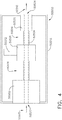
- An evacuator housing 50018 for a surgical evacuation system 50000 is shown in FIG. 1 .
- a pump and a filter are positioned within the evacuator housing 50018.
- Smoke drawn into the evacuator housing 50018 travels to the filter via a suction conduit 50036, and harmful toxins and offensive smells are filtered out of the smoke as it moves through the filter.
- the suction conduit can also be referred to as vacuum and/or evacuation conduit and/or tube, for example. Filtered air may then exit the surgical evacuation system as exhaust.
- various evacuation systems disclosed herein can also be configured to deliver fluids to a desired location, such as a surgical site.
- the suction conduit 50036 from the evacuator housing 50018 may terminate at a hand piece, such as the handpiece 50032.
- the handpiece 50032 comprises an electrosurgical instrument that includes an electrode tip 50034 and an evacuation conduit opening near and/or adjacent to the electrode tip 50034.
- the evacuation conduit opening is configured to capture the fluid and/or particulates that are released during a surgical procedure.
- the evacuation system 50000 is integrated into the electrosurgical instrument 50032.
- smoke S is being pulled into the suction conduit 50036.
- the evacuation system 50000 can include a separate surgical tool that comprises a conduit opening and is configured to suck the smoke out into the system.
- a tool comprising the evacuation conduit and opening can be snap fit onto an electrosurgical tool as depicted in FIG. 3 .
- a portion of a suction conduit 51036 can be positioned around (or adjacent to) an electrode tip 51034.
- the suction conduit 51036 can be releasably secured to a handpiece 51032 of an electrosurgical tool comprising the electrode tip 51034 with clips or other fasteners.
- an evacuation system 50500 includes the evacuator housing 50518, a filter 50502, an exhaust mechanism 50520, and a pump 50506.
- the evacuation system 50500 defines a flow path 50504 through the evacuator housing 50518 having an inlet port 50522 and an outlet port 50524.
- the filter 50502, the exhaust mechanism 50520, and the pump 50506 are sequentially arranged in-line with the flow path 50504 through the evacuator housing 50518 between the inlet port 50522 and the outlet port 50524.
- the inlet port 50522 can be fluidically coupled to a suction conduit, such as the suction conduit 50036 in FIG. 1 , for example, which can comprise a distal conduit opening positionable at the surgical site.
- the pump 50506 is configured to produce a pressure differential in the flow path 50504 by a mechanical action.
- the pressure differential is configured to draw smoke 50508 from the surgical site into the inlet port 50522 and along the flow path 50504. After the smoke 50508 has moved through the filter 50502, the smoke 50508 can be considered to be filtered smoke, or air, 50510, which can continue through the flow path 50504 and is expelled through the outlet port 50524.
- the flow path 50504 includes a first zone 50514 and a second zone 50516.
- the first zone 50514 is upstream from the pump 50506; the second zone 50516 is downstream from the pump 50506.
- the pump 50506 is configured to pressurize the fluid in the flow path 50504 so that the fluid in the second zone 50516 has a higher pressure than the fluid in the first zone 50514.
- a motor 50512 drives the pump 50506.
- the exhaust mechanism 50520 is a mechanism that can control the velocity, the direction, and/or other properties of the filtered smoke 50510 exiting the evacuation system 50500 at the outlet port 50524.
- the flow path 50504 through the evacuation system 50500 can be comprised of a tube or other conduit that substantially contains and/or isolates the fluid moving through the flow path 50504 from the fluid outside the flow path 50504.
- the first zone 50514 of the flow path 50504 can comprise a tube through which the flow path 50504 extends between the filter 50502 and the pump 50506.
- the second zone 50516 of the flow path 50504 can also comprise a tube through which the flow path 50504 extends between the pump 50506 and the exhaust mechanism 50520.
- the flow path 50504 also extends through the filter 50502, the pump 50506, and the exhaust mechanism 50520 so that the flow path 50504 extends continuously from the inlet port 50522 to the outlet port 50524.
- the smoke 50508 can flow into the filter 50502 at the inlet port 50522 and can be pumped through the flow path 50504 by the pump 50506 such that the smoke 50508 is drawn into the filter 50502.
- the filtered smoke 50510 can then be pumped through the exhaust mechanism 50520 and out the outlet port 50524 of the evacuation system 50500.
- the filtered smoke 50510 exiting the evacuation system 50500 at the outlet port 50524 is the exhaust, and can consist of filtered gases that have passed through the evacuation system 50500.
- the evacuation systems disclosed herein can be incorporated into a computer-implemented interactive surgical system, such as the system 100 ( FIG. 39 ) or the system 200 (FIG. 47), for example.
- the computer-implemented surgical system 100 can include at least one hub 106 and a cloud 104.
- the hub 106 includes a smoke evacuation module 126. Operation of the smoke evacuation module 126 can be controlled by the hub 106 based on its situational awareness and/or feedback from the components thereof and/or based on information from the cloud 104.
- the computer-implemented surgical systems 100 and 200, as well as situational awareness therefor, are further described herein.
- Situational awareness encompasses the ability of some aspects of a surgical system to determine or infer information related to a surgical procedure from data received from databases and/or instruments.
- the information can include the type of procedure being undertaken, the type of tissue being operated on, or the body cavity that is the subject of the procedure.
- the surgical system can, for example, improve the manner in which it controls the modular devices (e.g. a smoke evacuation system) that are connected to it and provide contextualized information or suggestions to the clinician during the course of the surgical procedure.
- Situational awareness is further described herein and in U.S. Provisional Patent Application Serial No. 62/611,341 , entitled INTERACTIVE SURGICAL PLATFORM, filed December 28, 2017, which is incorporated by reference herein in its entirety.
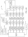
- FIG. 5 is a schematic representation of an electrosurgical system 50300 including a processor 50308.
- the electrosurgical system 50300 is powered by an AC source 50302, which provides either 120 V or 240 V alternating current.
- the voltage supplied by the AC source 50302 is directed to an AC/DC converter 50304, which converts the 120 V or 240 V of alternating current to 360 V of direct current.
- the 360 V of direct current is then directed to a power converter 50306 (e.g., a buck converter).
- the power converter 50306 is a step-down DC to DC converter.
- the power converter 50306 is adapted to step-down the incoming 360 V to a desired level within a range between 0-150 V.
- the processor 50308 can be programmed to regulate various aspects, functions, and parameters of the electrosurgical system 50300. For instance, the processor 50308 can determine the desired output power level at an electrode tip 50334, which can be similar in many respects to the electrode tip 50034 in FIG. 2 and/or the electrode tip 51034 in FIG. 3 , for example, and direct the power converter 50306 to step-down the voltage to a specified level so as to provide the desired output power.
- the processor 50308 is coupled to a memory 50310 configured to store machine executable instructions to operate the electrosurgical system 50300 and/or subsystems thereof.
- DAC digital-to-analog converter
- the DAC 50312 is adapted to convert a digital code created by the processor 50308 to an analog signal (current, voltage, or electric charge) which governs the voltage step-down performed by the power converter 50306.
- the power converter 50306 steps-down the 360 V to a level that the processor 50308 has determined will provide the desired output power level, the stepped-down voltage is directed to the electrode tip 50334 to effectuate electrosurgical treatment of a patient's tissue and is then directed to a return or ground electrode 50335.
- a voltage sensor 50314 and a current sensor 50316 are adapted to detect the voltage and current present in the electrosurgical circuit and communicate the detected parameters to the processor 50308 so that the processor 50308 can determine whether to adjust the output power level.
- typical wave generators are adapted to maintain the selected settings throughout an electrosurgical procedure.
- the operational parameters of a generator can be optimized during a surgical procedure based on one or more inputs to the processor 5308, such as inputs from a surgical hub, cloud, and/or situational awareness module, for example, as further described herein.
- the processor 50308 is coupled to a communication device 50318 to communicate over a network.
- the communication device includes a transceiver 50320 configured to communicate over physical wires or wirelessly.
- the communication device 50318 may further include one or more additional transceivers.
- the transceivers may include, but are not limited to cellular modems, wireless mesh network transceivers, Wi-Fi® transceivers, low power wide area (LPWA) transceivers, and/or near field communications transceivers (NFC).
- the communication device 50318 may include or may be configured to communicate with a mobile telephone, a sensor system (e.g., environmental, position, motion, etc.) and/or a sensor network (wired and/or wireless), a computing system (e.g., a server, a workstation computer, a desktop computer, a laptop computer, a tablet computer (e.g., iPad®, GalaxyTab® and the like), an ultraportable computer, an ultramobile computer, a netbook computer and/or a subnotebook computer; etc.
- a coordinator node e.g., a coordinator node.
- the transceivers 50320 may be configured to receive serial transmit data via respective UARTs from the processor 50308, to modulate the serial transmit data onto an RF carrier to produce a transmit RF signal and to transmit the transmit RF signal via respective antennas.
- the transceiver(s) are further configured to receive a receive RF signal via respective antennas that includes an RF carrier modulated with serial receive data, to demodulate the receive RF signal to extract the serial receive data and to provide the serial receive data to respective UARTs for provision to the processor.
- Each RF signal has an associated carrier frequency and an associated channel bandwidth. The channel bandwidth is associated with the carrier frequency, the transmit data and/or the receive data.
- Each RF carrier frequency and channel bandwidth are related to the operating frequency range(s) of the transceiver(s) 50320.
- Each channel bandwidth is further related to the wireless communication standard and/or protocol with which the transceiver(s) 50320 may comply.
- each transceiver 50320 may correspond to an implementation of a selected wireless communication standard and/or protocol, e.g., IEEE 802.11 a/b/g/n for Wi-Fi® and/or IEEE 802.15.4 for wireless mesh networks using Zigbee routing.
- the processor 50308 is coupled to a sensing and intelligent controls device 50324 that is coupled to a smoke evacuator 50326.
- the smoke evacuator 50326 can include one or more sensors 50327, and can also include a pump and a pump motor controlled by a motor driver 50328.
- the motor driver 50328 is communicatively coupled to the processor 50308 and a pump motor in the smoke evacuator 50326.
- the sensing and intelligent controls device 50324 includes sensor algorithms 50321 and communication algorithms 50322 that facilitate communication between the smoke evacuator 50326 and other devices to adapt their control programs.
- the sensing and intelligent controls device 50324 is configured to evaluate extracted fluids, particulates, and gases via an evacuation conduit 50336 to improve smoke extraction efficiency and/or reduce device smoke output, for example, as further described herein.
- the sensing and intelligent controls device 50324 is communicatively coupled to one or more sensors 50327 in the smoke evacuator 50326, one or more internal sensors 50330 and/or one or more external sensors 50332 of the electrosurgical system 50300.
- a processor can be located within an evacuator housing of a surgical evacuation system.
- a processor 50408 and a memory 50410 therefor are positioned within an evacuator housing 50440 of a surgical evacuation system 50400.
- the processor 50408 is in signal communication with a motor driver 50428, various internal sensors 50430, a display 50442, the memory 50410, and a communication device 50418.
- the communication device 50418 is similar in many respects to the communication device 50318 described above with respect to FIG. 5 .
- the communication device 50418 can allow the processor 50408 in the surgical evacuation system 50400 to communicate with other devices within a surgical system.
- the communication device 50418 can allow wired and/or wireless communication to one or more external sensors 50432, one or more surgical devices 50444, one or more hubs 50448, one or more clouds 50446, and/or one or more additional surgical systems and/or tools.
- the surgical evacuation system 50400 of FIG. 6 can be incorporated into the electrosurgical system 50300 of FIG. 5 in certain instances.
- the surgical evacuation system 50400 also includes a pump 50450, including a pump motor 50451 thereof, an evacuation conduit 50436, and an exhaust 50452.
- Various pumps, evacuation conduits and exhausts are further described herein.
- the surgical evacuation system 50400 can also include a sensing and intelligent controls device, which can be similar in many respects to the sensing and intelligent controls device 50324, for example.
- a sensing and intelligent controls device can be in signal communication with the processor 50408 and/or one or more of the sensors 50430 and/or external sensors 50432.
- the electrosurgical system 50300 ( FIG. 5 ) and/or the surgical evacuation system 50400 ( FIG. 6 ) can be programmed to monitor one or more parameters of a surgical system and can affect a surgical function based on one or more algorithms stored in a memory in signal communication with the processor 50308 and/or 50408.
- Various exemplary aspects disclosed herein can be implemented by such algorithms, for example.
- a processor and sensor system such as the processors 50308 and 50408 and respective sensor systems in communication therewith ( FIGS. 5 and 6 ), are configured to sense the airflow through a vacuum source in order to adjust parameters of the smoke evacuation system and/or external devices and/or systems that are used in tandem with the smoke evacuation system, such as an electrosurgical system, energy device, and/or generator, for example.
- the sensor system may include multiple sensors positioned along the airflow path of the surgical evacuation system. The sensors can measure a pressure differential within the evacuation system, in order to detect a state or status of the system between the sensors.
- the system between two sensors can be a filter, and the pressure differential can be used to increase the speed of the pump motor as flow through the filter is reduced, in order to maintain a flow rate through the system.
- the system can be a fluid trap of the evacuation system, and the pressure differential can be used to determine an airflow path through the evacuation system.
- the system can be the inlet and outlet (or exhaust) of the evacuation system, and the pressure differential can be used to determine the maximum suction load in the evacuation system in order to maintain the maximum suction load below a threshold value.
- a processor and sensor system such as the processors 50308 and 50408 and respective sensor systems in communication therewith ( FIGS. 5 and 6 ), are configured to detect the ratio of an aerosol or carbonized particulate, i.e. smoke, in the fluid extracted from a surgical site.
- the sensing system may include a sensor that detects the size and/or the composition of particles, which is used to select an airflow path through the evacuation system.
- the evacuation system can include a first filtering path, or first filtering state, and a second filtering path, or second filtering state, which can have different properties.
- the first path includes only a particulate filter
- the second path includes both a fluid filter and the particulate filter.
- the first path includes a particulate filter
- the second path includes the particulate filter and a finer particulate filter arranged in series. Additional and/or alternative filtering paths are also envisioned.
- a processor and sensor system such as the processors 50308 and 50408 and respective sensor systems in communication therewith ( FIGS. 5 and 6 ), are configured to perform a chemical analysis on the particles evacuated from within the abdomen cavity of a patient.
- the sensing and intelligent controls device 50324 may sense the particle count and type in order to adjust the power level of the ultrasonic generator in order to induce the ultrasonic blade to produce less smoke.
- the sensor systems may include sensors for detecting the particle count, the temperature, the fluid content, and/or the contamination percentage of the evacuated fluid, and can communicate the detected property or properties to a generator in order to adjust its output.
- the smoke evacuator 50326 and/or the sensing and intelligent controls device 50324 therefor can be configured to adjust the evacuation flow rate and/or the pump's motor speed and, at a predefined particulate level, may operably affect the output power or waveform of the generator to lower the smoke generated by the end effector.
- a processor and sensor system such as the processors 50308 and 50408 and respective sensor systems therewith ( FIGS. 5 and 6 ), are configured to evaluate particle count and contamination in the operating room by evaluating one or more properties in the ambient air and/or the exhaust from the evacuator housing.
- the particle count and/or the air quality can be displayed on the smoke evacuation system, such as on the evacuator housing, for example, in order to communicate the information to a clinician and/or to establish the effectiveness of the smoke evacuation system and filter(s) thereof.
- a processor such as the processor 50308 or the processor 50408 ( FIGS. 5 and 6 ), for example, is configured to compare a sample rate image obtained from an endoscope to the evacuator particle count from the sensing system (e.g. the sensing and intelligent controls device 50324) in order to determine a correlation and/or to adjust the rate of the pump's revolutions-per-minute (RPM).
- the activation of the generator can be communicated to the smoke evacuator such that an anticipated, required rate of smoke evacuation can be implemented.
- the generator activation can be communicated to the surgical evacuation system through a surgical hub, cloud communication system, and/or direct connection, for example.
- sensor systems and algorithms for a smoke evacuation system can be configured to control the smoke evacuator, and can adapt motor parameters thereof to adjust the filtering efficiency of the smoke evacuator based on the needs of the surgical field at a given time.
- an adaptive airflow pump speed algorithm is provided to automatically change the motor pump speed based on the sensed particulate into the inlet of the smoke evacuator and/or out of the outlet or exhaust of the smoke evacuator.
- the sensing and intelligent controls device 50324 FIG. 5
- the airflow through the evacuation system can be scalable based on the smoke into the evacuation system and/or a lack of filtered particles out of the smoke evacuation system.
- the auto-mode speed can provide automatic sensing and compensation for laparoscopic mode in certain instances.
- the evacuation system can include an electrical and communication architecture (see, e.g. FIGS. 5 and 6 ) that provides data collection and communication features, in order to improve interactivity with a surgical hub and a cloud.
- a surgical evacuation system and/or processor therefor such as the processor 50308 ( FIG. 5 ) and the processor 50408 ( FIG. 6 ), for example, can include a segmented control circuit that is energized in a staged method to check for errors, shorts, and/or safety checks of the system.
- the segmented control circuit may also be configured to have a portion energized and a portion not energized until the energized portion performs a first function.
- the segmented control circuit can include circuit elements to identify and display status updates to the user of attached components.
- the segmented control circuit also includes circuit elements for running the motor in a first state, in which the motor is activated by the user, and in a second state, in which the motor has not been activated by the user but runs the pump in a quieter manner and at a slower rate.
- a segmented control circuit can allow the smoke evacuator to be energized in stages, for example.
- the electrical and communication architecture for the evacuation system can also provide interconnectivity of the smoke evacuator with other components within the surgical hub for interactions, as well as communication of data with a cloud.
- Communication of surgical evacuation system parameters to a surgical hub and/or cloud can be provided to affect the output or operation of other attached devices.
- the parameters can be operational or sensed. Operational parameters include airflow, pressure differentials, and air quality. Sensed parameters include particulate concentration, aerosol percentage, and chemical analysis.
- the evacuation system such as the surgical evacuation system 50400, for example, can also include an enclosure and replaceable components, controls, and a display. Circuit elements are provided for communicating the security identification (ID) between such replaceable components. For example, communication between a filter and the smoke evacuation electronics can be provided to verify authenticity, remaining life of the component, to update parameters in the component, to log errors, and/or to limit the number and/or the type of components that can be identified by the system.
- the communication circuit can authenticate features for enabling and/or disabling of configuration parameters.
- the communication circuit can employ encryption and/or error handling schemes to manage security and proprietary relationships between the component and the smoke evacuation electronics. Disposable/re-useable components are included in certain instances.
- the evacuation systems can provide fluid management and extraction filters and airflow configurations.
- a surgical evacuation system including a fluid capture mechanism is provided where the fluid capture mechanism has a first and a second set of extraction or airflow control features, which are in series with each other to extract large and small fluid droplets, respectively.
- the airflow path can contain a recirculation channel or secondary fluid channel back to the primary reservoir from downstream of the exhaust port of the main fluid management chamber.
- an advanced pad can be coupled to the electrosurgical system.
- the ground electrode 50335 of the electrosurgical system 50300 FIG. 5
- the capacitive coupling return path pad can have small separable array elements, which can be used to sense nerve control signals and/or movement of select anatomic locations, in order to detect the proximity of the monopolar tip to a nerve bundle.
- An electrosurgical system can includes a signal generator, an electrosurgical instrument, a return electrode, and a surgical evacuation system.
- the generator may be an RF wave generator that produces RF electrical energy.
- Connected to the electrosurgical instrument is a utility conduit.
- the utility conduit includes a cable that communicates electrical energy from the signal generator to the electrosurgical instrument.
- the utility conduit also includes a vacuum hose that conveys captured/collected smoke and/or fluid away from a surgical site.
- FIG. 7 Such an exemplary electrosurgical system 50601 is shown in FIG. 7 . More specifically, the electrosurgical system 50601 includes a generator 50640, an electrosurgical instrument 50630, a return electrode 50646, and an evacuation system 50600.
- the electrosurgical instrument 50630 includes a handle 50632 and a distal conduit opening 50634 that is fluidically coupled to a suction hose 50636 of the evacuation system 50600.
- the electrosurgical instrument 50630 also includes an electrode that is powered by the generator 50640.
- a first electrical connection 50642, e.g., a wire extends from the electrosurgical instrument 50630 to the generator 50640.
- a second electrical connection 50644, e.g., a wire extends from the electrosurgical instrument 50630 to electrode, i.e., the return electrode 50646.
- the electrosurgical instrument 50630 can be a bipolar electrosurgical instrument.
- the distal conduit opening 50634 on the electrosurgical instrument 50630 is fluidically coupled to the suction hose 50636 that extends to a filter end cap 50603 of a filter that is installed in an evacuator housing 50618 of the evacuation system 50600.
- the distal conduit opening 50634 for the evacuation system 50600 can be on a handpiece or tool that is separate from the electrosurgical instrument 50630.
- the evacuation system 50600 can include a surgical tool that is not coupled to the generator 50640 and/or does not include tissue-energizing surfaces.
- the distal conduit opening 50634 for the evacuation system 50600 can be releasably attached to an electrosurgical tool.
- the evacuation system 50600 can include a clip-on or snap-on conduit terminating at a distal conduit opening, which can be releasably attached to a surgical tool (see, e.g., FIG. 3 ).
- the electrosurgical instrument 50630 is configured to deliver electrical energy to target tissue of a patient to cut the tissue and/or cauterize blood vessels within and/or near the target tissue, as described herein. Specifically, an electrical discharge is provided by the electrode tip to the patient in order to cause heating of cellular matter of the patient that is in close contact with or adjacent to electrode tip. The tissue heating takes place at an appropriately high temperature to allow the electrosurgical instrument 50630 to be used to perform electrosurgery.
- the return electrode 50646 is either applied to or placed in close proximity to the patient (depending on the type of return electrode), in order to complete the circuit and provide a return electrical path to the generator 50640 for energy that passes into the patient's body.
- the evacuation conduit opening 50634 is near the electrode tip, the evacuation system 50600 is configured to capture the smoke that is released during a surgical procedure. Vacuum suction may draw the smoke into the conduit opening 50634, through the electrosurgical instrument 50630, and into the suction hose 50636 toward the evacuator housing 50618 of the evacuation system 50600.
- the evacuator housing 50618 of the evacuation system 50600 ( FIG. 7 ) is depicted.
- the evacuator housing 50618 includes a socket 50620 that is dimensioned and structured to receive a filter.
- the evacuator housing 50618 can completely or partially encompass the internal components of the evacuator housing 50618.
- the socket 50620 includes a first receptacle 50622 and a second receptacle 50624.
- a transition surface 50626 extends between the first receptacle 50622 and the second receptacle 50624.
- the socket 50620 is depicted along a cross sectional plane indicated in FIG. 8 .
- the socket 50620 includes a first end 50621 that is open to receive a filter and a second end 50623 in communication with a flow path 50699 through the evacuator housing 50618.
- a filter 50670 FIGS. 10 and 11 ) may be removably positioned with the socket 50620.
- the filter 50670 can be inserted and removed from the first end 50621 of the socket 50620.
- the second receptacle 50624 is configured to receive a connection nipple of the filter 50670.
- Surgical evacuation systems often use filters to remove unwanted pollutants from the smoke before the smoke is released as exhaust.
- the filters can be replaceable.
- the reader will appreciate that the filter 50670 depicted in FIGS. 10 and 11 can be employed in various evacuation systems disclosed herein.
- the filter 50670 can be a replaceable and/or disposable filter.
- the filter 50670 includes a front cap 50672, a back cap 50674, and a filter body 50676 disposed therebetween.
- the front cap 50672 includes a filter inlet 50678, which, in certain instances, is configured to receive smoke directly from the suction hose 50636 ( FIG. 7 ) or other smoke source.
- the front cap 50672 can be replaced by a fluid trap (e.g. the fluid trap 50760 depicted in FIGS. 14-17 ) that directs the smoke directly from the smoke source, and after removing at least a portion of the fluid therefrom, passes the partially processed smoke into the filter body 50676 for further processing.
- the filter inlet 50678 can be configured to receive smoke via a fluid trap exhaust port, such as a port 50766 in a fluid trap 50760 ( FIGS. 14-17 ) to communicate partially processed smoke into the filter 50670.
- the smoke can be filtered by components housed within the filter body 50676.
- the filtered smoke can then exit the filter 50670 through a filter exhaust 50680 defined in the back cap 50674 of the filter 50670.
- suction generated in the evacuator housing 50618 of the evacuation system 50600 can be communicated to the filter 50670 through the filter exhaust 50680 to pull the smoke through the internal filtering components of the filter 50670.
- a filter often includes a particulate filter and a charcoal filter.
- the particulate filter can be a high-efficiency particulate air (HEPA) filter or an ultra-low penetration air (ULPA) filter, for example.
- HEPA high-efficiency particulate air
- ULPA ultra-low penetration air
- the ULPA filtration utilizes a depth filter that is similar to a maze.
- the particulate can be filtered using at least one of the following methods: direct interception (in which particles over 1.0 micron are captured because they are too large to pass through the fibers of the media filter), inertial impaction (in which particles between 0.5 and 1.0 micron collide with the fibers and remain there, and diffusional interception (in which particles less than 0.5 micron are captured by the effect of Brownian random thermal motion as the particles "search out” fibers and adhere to them).
- the charcoal filter is configured to remove toxic gases and/or odor generated by the surgical smoke.
- the charcoal can be "activated” meaning it has been treated with a heating process to expose the active absorption sites.
- the charcoal can be from activated virgin coconut shells, for example.
- the filter 50670 includes a coarse media filter layer 50684 followed by a fine particulate filter layer 50686.
- the filter 50670 may consist of a single type of filter.
- the filter 50670 can include more than two filter layers and/or more than two different types of filter layers.
- the smoke is drawn through a carbon reservoir 50688 in the filter 50670 to remove gaseous contaminants within the smoke, such as volatile organic compounds, for example.
- the carbon reservoir 50688 can comprise a charcoal filter.
- the filtered smoke which is now substantially free of particulate matter and gaseous contaminants, is drawn through the filter exhaust 50680 and into the evacuation system 50600 for further processing and/or elimination.
- the filter 50670 includes a plurality of dams between components of the filter body 50676.
- a first dam 50690 is positioned intermediate the filter inlet 50678 ( FIG. 10 ) and a first particulate filter, such as the coarse media filter 50684, for example.
- a second dam 50692 is positioned intermediate a second particulate filter, such as the fine particulate filter 50686, for example, and the carbon reservoir 50688.
- a third dam 50694 is positioned intermediate the carbon reservoir 50688 and the filter exhaust 50680.
- the dams 50690, 50692, and 50694 can comprise a gasket or O-ring, which is configured to prevent movement of the components within the filter body 50676.
- the size and shape of the dams 50690, 50692, and 50694 can be selected to prevent distention of the filter components in the direction of the applied suction.
- the coarse media filter 50684 can include a low-air-resistant filter material, such as fiberglass, polyester, and/or pleated filters that are configured to remove a majority of particulate matter larger than 10 ⁇ m, for example.
- this includes filters that remove at least 85% of particulate matter larger than 10 ⁇ m, greater than 90% of particulate matter larger than 10 ⁇ m, greater than 95% of particular matter larger than 10 ⁇ m, greater than 99% of particular matter larger than 10 ⁇ m, greater than 99.9% particulate matter larger than 10 ⁇ m, or greater than 99.99% particulate matter larger than 10 ⁇ m.
- the coarse media filter 50684 can include a low-air-resistant filter that removes the majority of particulate matter greater than 1 ⁇ m.
- this includes filters that remove at least 85% particulate matter larger than 1 ⁇ m, greater than 90% of particulate matter larger than 1 ⁇ m, greater than 95% of particular matter larger than 1 ⁇ m, greater than 99% of particular matter larger than 1 ⁇ m, greater than 99.9% particulate matter larger than 1 ⁇ m, or greater than 99.99% particulate matter larger than 1 ⁇ m.
- the fine particulate filter 50686 can include any filter of higher efficiency than the coarse media filter 50684. This includes, for example, filters that are capable of filtering a higher percentage of the same sized particles as the coarse media filter 50684 and/or capable of filtering smaller sized particles than the coarse media filter 50684.
- the fine particulate filter 50686 can include a HEPA filter or an ULPA filter. Additionally or alternatively, the fine particulate filter 50686 can be pleated to increase the surface area thereof.
- the coarse media filter 50684 includes a pleated HEPA filter and the fine particulate filter 50686 includes a pleated ULPA filter.
- the carbon reservoir 50688 is bounded by porous dividers 50696 and 50698 disposed between the intermediate and terminal dams 50692 and 50694, respectively.
- the porous dividers 50696 and 50698 are rigid and/or inflexible and define a constant spatial volume for the carbon reservoir 50688.
- the carbon reservoir 50688 can include additional sorbents that act cumulatively with or independently from the carbon particles to remove gaseous pollutants.
- the additional sorbents can include, for example, sorbents such as magnesium oxide and/or copper oxide, for example, which can act to adsorb gaseous pollutants such as carbon monoxide, ethylene oxide, and/or ozone, for example.
- additional sorbents are dispersed throughout the reservoir 50688 and/or are positioned in distinct layers above, below, or within the reservoir 50688.
- the evacuation system 50500 includes the pump 50506 within the evacuator housing 50518.
- the evacuation system 50600 depicted in FIG. 7 can include a pump located in the evacuator housing 50618, which can generate suction to pull smoke from the surgical site, through the suction hose 50636 and through the filter 50670 ( FIGS. 10 and 11 ).
- the pump can create a pressure differential within the evacuator housing 50618 that causes the smoke to travel into the filter 50670 and out an exhaust mechanism (e.g. exhaust mechanism 50520 in FIG. 4 ) at the outlet of the flow path.
- the filter 50670 is configured to extract harmful, foul, or otherwise unwanted particulates from the smoke.
- the pump can be disposed in-line with the flow path through the evacuator housing 50618 such that the gas flowing through the evacuator housing 50618 enters the pump at one end and exits the pump at the other end.
- the pump can provide a sealed positive displacement flow path.
- the pump can produce the sealed positive displacement flow path by trapping (sealing) a first volume of gas and decreasing that volume to a second smaller volume as the gas moves through the pump. Decreasing the volume of the trapped gas increases the pressure of the gas.
- the second pressurized volume of gas can be released from the pump at a pump outlet.
- the pump can be a compressor.
- the pump can comprise a hybrid regenerative blower, a claw pump, a lobe compressor, and/or a scroll compressor.
- Positive displacement compressors can provide improved compression ratios and operating pressures while limiting vibration and noise generated by the evacuation system 50600.
- the evacuation system 50600 can include a fan for moving fluid therethrough.
- FIG. 12 An example of a positive displacement compressor, e.g. a scroll compressor pump 50650, is depicted in FIG. 12 .
- the scroll compressor pump 50650 includes a stator scroll 50652 and a moving scroll 50654.
- the stator scroll 50652 can be fixed in position while the moving scroll 50654 orbits eccentrically.
- the moving scroll 50654 can orbit eccentrically such that it rotates about the central longitudinal axis of the stator scroll 50652.
- the central longitudinal axes of the stator scroll 50652 and the moving scroll 50654 extend perpendicular to the viewing plane of the scrolls 50652, 50654.
- the stator scroll 50652 and the moving scroll 50654 are interleaved with each other to form discrete sealed compression chambers 50656.
- a gas can enter the scroll compressor pump 50650 at an inlet 50658.
- the compression chamber 50656 is configured to move a discrete volume of gas along the spiral contour of the scrolls 50652 and 50654 toward the center of the scroll compressor pump 50650.
- the compression chamber 50656 defines a sealed space in which the gas resides.
- the compression chamber 50656 decreases in volume. This decrease in volume increases the pressure of the gas inside the compression chamber 50656.
- the gas inside the sealed compression chamber 50656 is trapped while the volume decreases, thus pressurizing the gas. Once the pressurized gas reaches the center of the scroll compressor pump 50650, the pressurized gas is released through an outlet 50659.
- the evacuation system 50700 can be similar in many respects to the evacuation system 50600 ( FIG. 7 ).
- the evacuation system 50700 includes the evacuator housing 50618 and the suction hose 50636.
- the evacuation system 50600 is configured to produce suction and thereby draw smoke from the distal end of the suction hose 50636 into the evacuator housing 50618 for processing.
- the suction hose 50636 is not connected to the evacuator housing 50618 through the filter end cap 50603 in FIG. 13 .
- suction hose 50636 is connected to the evacuator housing 50618 through the fluid trap 50760.
- a filter similar to the filter 50670 can be positioned within the socket of the evacuator housing 50618 behind the fluid trap 50760.
- the fluid trap 50760 is a first processing point that extracts and retains at least a portion of the fluid (e.g. liquid) from the smoke before relaying the partially-processed smoke to the evacuation system 50700 for further processing and filtration.
- the evacuation system 50700 is configured to process, filter, and otherwise clean the smoke to reduce or eliminate unpleasant odors or other problems associated with smoke generation in the surgical theater (or other operating environment), as described herein.
- the fluid trap 50760 can, among other things, increase the efficiency of the evacuation system 50700 and/or increase the life of filters associated therewith, in certain instances.
- the fluid trap 50760 is depicted detached from the evacuator housing 50618 ( FIG. 13 ).
- the fluid trap 50760 includes an inlet port 50762 defined in a front cover or surface 50764 of the fluid trap 50760.
- the inlet port 50762 can be configured to releasably receive the suction hose 50636 ( FIG. 13 ).
- an end of the suction hose 50636 can be inserted at least partially within the inlet port 50762 and can be secured with an interference fit therebetween.
- the interference fit can be a fluid tight and/or airtight fit so that substantially all of the smoke passing through the suction hose 50636 is transferred into the fluid trap 50760.
- other mechanisms for coupling or joining the suction hose 50636 to the inlet port 50762 can be employed such as a latch-based compression fitting, an O-ring, threadably coupling the suction hose 50636 with the inlet port 50762, for example, and/or other coupling mechanisms.
- a fluid tight and/or airtight fit between the suction hose 50636 and the fluid trap 50760 is configured to prevent fluids and/or other materials in the evacuated smoke from leaking at or near the junction of these components.
- the suction hose 50636 can be associated with the inlet port 50762 through an intermediate coupling device, such as an O-ring and/or adaptor, for example, to further ensure an airtight and/or fluid tight connection between the suction hose 50636 and the fluid trap 50760.
- the fluid trap 50760 includes the exhaust port 50766.
- the exhaust port extends away from a rear cover or surface 50768 of the fluid trap 50760.
- the exhaust port 50766 defines an open channel between an interior chamber 50770 of the fluid trap 50760 and the exterior environment.
- the exhaust port 50766 is sized and shaped to tightly associate with a surgical evacuation system or components thereof.
- the exhaust port 50766 can be sized and shaped to associate with and communicate at least partially processed smoke from the fluid trap 50760 to a filter housed within an evacuator housing 50618 ( FIG. 13 ).
- the exhaust port 50766 can extend away from the front plate, a top surface, or a side surface of the fluid trap 50760.
- the exhaust port 50766 includes a membrane, which spaces the exhaust port 50766 apart from the evacuator housing 50618.
- a membrane can act to prevent water or other liquid collected in the fluid trap 50760 from being passed through the exhaust port 50766 and into the evacuator housing 50618 while permitting air, water and/or vapor to freely pass into the evacuator housing 50618.
- a high flow rate microporous polytetrafluoroethylene (PTFE) can be positioned downstream of the exhaust port 50766 and upstream of a pump to protect the pump or other components of the evacuation system 50700 from damage and/or contamination.
- the fluid trap 50760 also includes a gripping region 50772, which is positioned and dimensioned to assist a user in handling the fluid trap 50760 and/or connecting the fluid trap 50760 with the suction hose 50636 and/or the evacuator housing 50618.
- the gripping region 50772 is depicted as being an elongate recess; however, the reader will readily appreciate that the gripping region 50772 may include at least one recess, groove, protrusion, tassel, and/or ring, for example, which can be sized and shaped to accommodate a user's digits or to otherwise provide a gripping surface.
- the interior chamber 50770 of the fluid trap 50760 is depicted.
- the relative positioning of the inlet port 50762 and the exhaust port 50766 is configured to promote the extraction and the retention of fluid from the smoke as it passes into the fluid trap 50760.
- the inlet port 50762 can comprise a notched cylindrical shape, which can direct the smoke and the accompanying fluid towards a fluid reservoir 50774 of the fluid trap 50760 or otherwise directionally away from the exhaust port 50766.
- An example of such a fluid flow is depicted with arrows A, B, C, D, and E in FIG. 17 .
- the smoke entering the inlet port 50762 is initially directed primarily downward into the fluid reservoir 50774 of the fluid trap 50760 (illustrated by the arrows B).
- the directional flow of smoke through the fluid trap 50760 can ensure that liquids within the smoke are extracted and retained within the lower portion (e.g. the fluid reservoir 50774) of the fluid trap 50760. Furthermore, the relative positioning of the exhaust port 50766 vertically above the inlet port 50762 when the fluid trap 50760 is in an upright position is configured to discourage liquid from inadvertently being carried through the exhaust port 50766 by the flow of smoke while not substantially hindering fluid flow into and out of the fluid trap 50760. Additionally, in certain instances, the configuration of the inlet port 50762 and the outlet port 50766 and/or the size and shape of the fluid trap 50760 itself, can enable the fluid trap 50760 to be spill resistant.
- an evacuation system can include a plurality of sensors and intelligent controls, as further described herein with respect to FIGS. 5 and 6 , for example.
- an evacuation system can include one or more temperatures sensors, one or more fluid detection sensors, one or more pressure sensors, one or more particle sensors, and/or one or more chemical sensors.
- a temperature sensor can be positioned to detect the temperature of a fluid at the surgical site, moving through a surgical evacuation system, and/or being exhaust into a surgical theater from a surgical evacuation system.
- a pressure sensor can be positioned to detect a pressure within the evacuation system, such as within the evacuator housing.
- a pressure sensor can be positioned upstream of the filter, between the filter and the pump, and/or downstream of the pump.
- a pressure sensor can be positioned to detect a pressure in the ambient environment outside of the evacuation system.
- a particle sensor can be positioned to detect particles within the evacuation system, such as within the evacuator housing.
- a particle sensor can be upstream of the filter, between the filter and the pump, and/or downstream of the pump, for example.
- a particle sensor can be positioned to detect particles in the ambient environment in order to determine the air quality in the surgical theater, for example.
- FIG. 18 An evacuator housing 50818 for an evacuation system 50800 is schematically depicted in FIG. 18 .
- the evacuator housing 50818 can be similar in many respects to the evacuator housings 50018 and/or 50618, for example, and/or can be incorporated into various evacuation systems disclosed herein.
- the evacuator housing 50818 includes numerous sensors, which are further described herein. The reader will appreciate that certain evacuator housings may not include each sensor depicted in FIG. 18 and/or may include additional sensor(s). Similar to the evacuator housings 50018 and 50618 disclosed herein, the evacuator housing 50818 of FIG. 18 includes an inlet 50822 and an outlet 50824. A fluid trap 50860, a filter 50870, and a pump 50806 are sequentially aligned along a flow path 50804 through the evacuator housing 50818 between the inlet 50822 and the outlet 50824.
- An evacuator housing can include modular and/or replaceable components, as further described herein.
- an evacuator housing can include a socket or a receptacle 50871 dimensioned to receive a modular fluid trap and/or a replaceable filter.
- a fluid trap and a filter can be incorporated into a single interchangeable module 50859, as depicted in FIG. 18 .
- the fluid trap 50860 and the filter 50870 form the interchangeable module 50859, which can be modular and/or replaceable, and can be removably installed in the receptacle 50871 in the evacuator housing 50818.
- the fluid trap 50860 and the filter 50870 can be separate and distinct modular components, which can be assembled together and/or separately installed in the evacuator housing 50818.
- the evacuator housing 50818 includes a plurality of sensors for detecting various parameters therein and/or parameters of the ambient environment. Additionally or alternatively, one or more modular components installed in the evacuator housing 50818 can include one or more sensors.
- the interchangeable module 50859 includes a plurality of sensors for detecting various parameters therein.
- the evacuator housing 50818 and/or a modular component(s) compatible with the evacuator housing 50818 can include a processor, such as the processor 50308 and 50408 ( FIGS. 5 and 6 , respectively), which is configured to receive inputs from one or more sensors and/or to communicate outputs to one more systems and/or drivers.
- a processor such as the processor 50308 and 50408 ( FIGS. 5 and 6 , respectively)
- smoke from a surgical site can be drawn into the inlet 50822 to the evacuator housing 50818 via the fluid trap 50860.
- the flow path 50804 through the evacuator housing 50818 in FIG. 18 can comprise a sealed conduit or tube 50805 extending between the various in-line components.
- the smoke can flow past a fluid detection sensor 50830 and a chemical sensor 50832 to a diverter valve 50834, which is further described herein.
- a fluid detection sensor such as the sensor 50830, can detect fluid particles in the smoke.
- the fluid detection sensor 50830 can be a continuity sensor.
- the fluid detection sensor 50830 can include two spaced-apart electrodes and a sensor for detecting the degree of continuity therebetween. When no fluid is present, the continuity can be zero, or substantially zero, for example.
- the chemical sensor 50832 can detect the chemical properties of the smoke.
- fluid can be directed into a condenser 50835 of the fluid trap 50860 and the smoke can continue toward the filter 50870.
- Baffles 50864 are positioned within the condenser 50835 to facilitate the condensation of fluid droplets from the smoke into a reservoir in the fluid trap 50860.
- a fluid detection sensor 50836 can ensure any fluid in the evacuator housing is entirely, or at least substantially, captured within the fluid trap 50860.
- the smoke can then be directed to flow into the filter 50870 of the interchangeable module 50859.
- the smoke can flow past a particle sensor 50838 and a pressure sensor 50840.
- the particle sensor 50838 can comprise a laser particle counter, as further described herein.
- the smoke can be filtered via a pleated ultra-low penetration air (ULPA) filter 50842 and a charcoal filter 50844, as depicted in FIG. 18 .
- ULPA ultra-low penetration air
- the filtered smoke can flow past a pressure sensor 50846 and can then continue along the flow path 50804 within the evacuator housing 50818 toward the pump 50806.
- the filtered smoke can flow past a particle sensor 50848 and a pressure sensor 50850 at the outlet to the evacuator housing 50818.
- the particle sensor 50848 can comprise a laser particle counter, as further described herein.
- the evacuator housing 50818 in FIG. 18 also includes an air quality particle sensor 50852 and an ambient pressure sensor 50854 to detect various properties of the ambient environment, such as the environment within the surgical theater.
- the air quality particle sensor, or external/ambient air particle sensor, 50852 can comprise a laser particle counter in at least one form.
- the various sensors depicted in FIG. 18 are further described herein.
- alternative sensing means can be utilized in the smoke evacuation systems disclosed herein.
- alternative sensors for counting particles and/or determining particulate concentration in a fluid are further disclosed herein.
- the fluid trap 50860 depicted in FIG. 18 can be configured to prevent spillage and/or leakage of the captured fluid.
- the geometry of the fluid trap 50860 can be selected to prevent the captured fluid from spilling and/or leaking.
- the fluid trap 50860 can include baffles and/or splatter screens, such as the screen 50862, for preventing the captured fluid from splashing out of the fluid trap 50860.
- the fluid trap 50860 can include sensors for detecting the volume of fluid within the fluid trap and/or determining if the fluid trap 50860 is filled to capacity.
- the fluid trap 50860 may include a valve for empty the fluid therefrom.
- the filter 50870 can include additional and/or fewer filtering levels.
- the filter 50870 can include one or more filtering layers selected from the following group of filters: a course media filter, a fine media filter, and a sorbent-based filter.
- the course media filter can be a low-air-resistant filter, which can be comprised of fiberglass, polyester, and/or pleated filters, for example.
- the fine media filter can be a high efficiency particulate air (HEPA) filter and/or ULPA filter.
- the sorbent-based filter can be an activated-carbon filter, for example.
- the pump 50806 depicted in FIG. 18 can be replaced by and/or used in combination with another compressor and/or pump, such as a hybrid regenerative blower, a claw pump, and/or a lobe compressor, for example.
- a hybrid regenerative blower such as a hybrid regenerative blower, a claw pump, and/or a lobe compressor, for example.
- a lobe compressor such as a hybrid regenerative blower, a claw pump, and/or a lobe compressor, for example.
- various alternative pumping arrangements and geometries can be employed to generate suction within the flow path 50804 to draw smoke into the evacuator housing 50818.
- the various sensors in an evacuation system can communicate with a processor.
- the processor can be incorporated into the evacuation system and/or can be a component of another surgical instrument and/or a surgical hub.
- Various processors are further described herein.
- An on-board processor can be configured to adjust one or more operational parameters of the evacuator system (e.g. a motor for the pump 50806) based on input from the sensor(s). Additionally or alternatively, an on-board processor can be configured to adjust one or more operational parameters of another device, such as an electrosurgical tool and/or imaging device based on input from the sensor(s).
- FIG. 19 another evacuator housing 50918 for an evacuation system 50900 is depicted.
- the evacuator housing 50918 in FIG. 19 can be similar in many respects to the evacuator housing 50818 in FIG. 18 .
- the evacuator housing 50918 defines a flow path 50904 between an inlet 50922 to the evacuator housing 50918 and an outlet 50924 to the evacuator housing 50918.
- a fluid trap 50960, a filter 50970, and a pump 50906 are sequentially arranged.
- the evacuator housing 50918 can include a socket or a receptacle 50971 dimensioned to receive a modular fluid trap and/or a replaceable filter, similar to the receptacle 50871, for example.
- a diverter valve 50934 fluid can be directed into a condenser 50935 of the fluid trap 50960 and the smoke can continue toward the filter 50970.
- the fluid trap 50960 can include baffles, such as the baffles 50964, and/or splatter screens, such as the screen 50962, for example, for preventing the captured fluid from splashing out of the fluid trap 50960.
- the filter 50970 includes a pleated ultra-low penetration air (ULPA) filter 50942 and a charcoal filter 50944.
- ULPA ultra-low penetration air
- a sealed conduit or tube 50905 extends between the various in-line components.
- the evacuator housing 50918 also includes the sensors 50830, 50832, 50836, 50838, 50840, 50846, 50848, 50850, 50852, and 50854 which are further described herein and shown in FIG. 18 and FIG. 19 .
- the evacuator housing 50918 also includes a centrifugal blower arrangement 50980 and a recirculating valve 50990.
- the recirculating valve 50990 can selectively open and close to recirculate fluid through the fluid trap 50960. For example, if the fluid detection sensor 50836 detects a fluid, the recirculating valve 50990 can be opened such that the fluid is directed back away from the filter 50970 and back into the fluid trap 50960. If the fluid detection sensor 50836 does not detect a fluid, the valve 50990 can be closed such that the smoke is directed into the filter 50970. When fluid is recirculated via the recirculating valve 50990, the fluid can be drawn through a recirculation conduit 50982.
- the centrifugal blower arrangement 50980 is engaged with the recirculation conduit 50982 to generate a recirculating suction force in the recirculation conduit 50982. More specifically, when the recirculating valve 50990 is open and the pump 50906 is activated, the suction force generated by the pump 50906 downstream of the filter 50970 can generate rotation of the first centrifugal blower, or squirrel cage, 50984, which can be transferred to the second centrifugal blower, or squirrel cage, 50986, which draws the recirculated fluid through the recirculating valve 50990 and into the fluid trap 50960.
- control schematics of FIGS. 5 and 6 can be utilized with the various sensor systems and evacuator housings of FIGS. 18 and 19 .
- providing network services to medical devices may expose vulnerabilities of the medical devices to malicious attacks.
- these services may be vulnerable to security attacks from components inside the medical devices. That is, the firewall services may not have information with respect to the types, products, configurations, or authenticity of the components of the medical devices and, thus, may not be able to protect the medical device system from malicious attacks coming from unauthentic/unauthorized components of the medical devices.
- an unauthentic/unauthorized component e.g., filter device
- the unauthentic/unauthorized component may not be compatible with other authentic/authorized components of the medical device, which may result in reduction in the lifetime and/or performance of the overall medical components. This may also lead to an unexpected interruption in operation of the medical devices.
- a surgical evacuation system may include a communication circuit that may facilitate communication between a smoke evacuation device and a replaceable filter device having a plurality of filter components.
- the communication circuit may authenticate the filter device (including the plurality of filter components), verify a remaining life of the filter device, update parameters output from the filter device, and record errors output from the filter device.
- the communication circuit may limit a number or a type of a filter component that can be identified by the surgical evacuation system, and may enable/disable the plurality of filter components based on a result of the authentication.
- the communication circuit may authenticate the filter device/components by using filter component information, which may include a product type, a product name, a unique device identifier, a product trademark, a serial number, or a configuration parameter of the filter device/components.
- filter component information may include a product type, a product name, a unique device identifier, a product trademark, a serial number, or a configuration parameter of the filter device/components.
- the filter device and/or the communication circuit may encrypt or decrypt data/parameters communicated between the filter device and the communication circuit.
- the surgical evacuation system may be able to detect an unauthentic/unauthorized component of a medical device, protect data/parameters of the medical device by encryption, and check possible issues in the filter device in advance by checking the remaining life and errors of the filter components. This may advantageously allow the surgical system to prevent possible malicious attacks and degradation in performance that may be caused by the unauthentic/unauthorized component and to continue to operate the surgical evacuation system without an unexpected interruption in the medical device operation.
- FIG. 20 depicts a high-level component diagram of an example smoke evacuation system 58100 in accordance with one or more aspects of the present disclosure.
- the smoke evacuation system 58100 may include a smoke evacuation device 58105 having a pump 58160 and a motor 58165 operably coupled to the pump 58160, a display device 58170, a communication device 58180, a processor 58110, a memory 58120, and one or more sensors 58140A-B.
- the smoke evacuation device 58105 may include a filter device 58150 and a filter communication circuit 58130.
- the filter device 58150 may be in communication with the smoke evacuation device 58105 (e.g., processor 58110) through the filter communication circuit 58130.
- the smoke evacuation system 58100 may be similar to the smoke evacuation system depicted in FIG. 6 .
- the processor 58110 may be in signal communication with a motor driver or the motor 58165, various sensors 58140A-B, the display device 58170, the memory 58120, and the communication device 58180.
- the communication device 58180 may be similar to the communication device described above with respect to FIGS. 5 and 6 . That is, the communication device 58180 may allow the processor 58110 in the smoke evacuation system 58100 to communicate with other devices within the surgical system.
- the communication device 58180 may allow wired and/or wireless communication to external sensors, surgical devices, hubs, clouds, and/or various additional surgical systems and/or tools.
- the smoke evacuation system of FIG. 20 can be incorporated into the surgical system of FIG. 5 in certain instances.
- the filter device 58150 may be coupled to a sucking conduit 58155.
- An exhaust mechanism 58190 may be coupled to the pump 58160.
- the exhaust mechanism 58190 may be similar to the exhaust mechanism 50520.
- the suction conduit 58155, the filter device 58150, the pump 58160, and the exhaust mechanism 58190 may be sequentially arranged in-line with a flow path (e.g., the flow path 50504) between an inlet port (e.g., inlet port 50522) and an outlet port (e.g., outlet port 50524).
- the inlet may be fluidically coupled to the suction conduit 58155 comprising a distal conduit opening at the surgical site.
- the exhaust mechanism 58190 is depicted as located outside of the smoke evacuation device 58105, in some examples, the exhaust mechanism 58190 may be located in the smoke evacuation device 58105.
- the processor 58110 may be in signal communication with the filter communication circuit 58130 for communication between the filter device 58150 and the smoke evacuation device 58105.
- the filter communication circuit 58130 may be located in the smoke evacuation device 58105 or the filter device 58150. In other examples, the communication circuit 58130 may be located outside of the smoke evacuation device 58105. In some examples, the communication circuit 58130 may be part of the sensing and intelligent controls device depicted in FIG. 5 .
- FIG. 21 illustrates a filter communication circuit 58130 according to an example embodiment of the present disclosure.
- the filter communication circuit 58220 may include a master controller 58210, an authentication unit 58220, an error logging unit 58230, an updating unit 58240, an encryption/description unit 58250, a remaining life verification unit 58260, and a data storage unit 58270.
- the master controller 58210 may be in signal communication with the processor 58110 and control other units 58220-58270 in the filter communication circuit 58130.
- the processor 58110 may act as the master controller 58210.
- FIG. 22 illustrates a filter device 58150 according to an example embodiment of the present disclosure.
- the filter device 58150 may include a plurality of filter components.
- the filter components may include a controller 58310, a filter element unit 58320, and a filter sensor unit 58330.
- the filter element unit 58320 may include one or more filter elements 58325A-C.
- the filter sensor unit 58330 may include one or more filter sensors 58335A-C.
- the controller 58310 may control and be in communication with the filter element unit 58320 and the filter sensor unit 58330.
- the filter device 58150 may be similar to the examples (e.g., filter 50670) depicted in FIGS. 10 , 11 , 18 , and 19 .
- the one or more filter elements 58325A-C may be the fluid filter, coarse media filter 50684, fine particulate filter 50686, particulate filter, carbon reservoir 50688, or charcoal filter depicted in FIGS. 10 , 11 , 18 , and 19 or any other filters in the filter device 58150.
- the filter elements 58325A-C may also include the diverter valve, the baffles, the squirrel cage, or any other elements (e.g., dams 50690, 50692, 50694, back cap 50674, etc.) in the filter device other than the sensors.
- the one or more filter sensors 58335A-C may be similar to the examples (e.g., fluid detect sensors 50830, chemical sensor 50832, fluid sensor 50836, pressure sensor 50840, laser particle counter 50838, etc.) depicted in FIGS. 18 and 19 .
- the controller 58310 in the filter device 58150 may be in signal communication with the master controller 58210 of the filter communication circuit 58130.
- the filter device 58150 may encrypt the parameters output from the plurality of filter components before sending the parameters to the communication circuit 58130.
- the communication circuit e.g., encryption/description unit 58250
- the authentication unit 58220 may authenticate/verify the filter device 58150 or the plurality of filter components.
- the authentication unit 58220 may identify the number of filter components that is attached in the filter device 58150.
- the authentication unit 58220 may also limit the number or type of a filter component that can be identified by the communication circuit. For example, if the filter component is not the type of a component authorized to be used in the filter device 58150, or the number of filter components used in the filter device 58150 is equal to or greater than a predetermined value (e.g., 10, 20, 50, etc.), the authentication unit 58220 may disable the filter component or the filter device 58150.
- the authentication unit 58220 may also enable or disable the filter device 58150 or the plurality of filter components based on a result of the authentication.
- the error logging unit 58230 may record errors or error messages from the plurality of filter components or the filter device 58150. In some examples, the error logging unit 58230 may record the errors and error messages in the data storage unit 58270.
- the filter communication circuit 58130 may read the error messages and use the error messages to figure out what happened in the filter device 58150. Examples of the errors and error messages may include errors that occur due to sensor/filter failures, strange/dangerous chemicals detected by sensors/filters, moisture detected in particulate filters; clogged filters, pressure differential (e.g., between the pressure sensors 50840 and 50846) over a predetermined value, and unauthentic/unauthorized filter device/component.
- the updating unit 58240 may update parameters output from the plurality of filter components.
- the parameters updated may be operational or sensed.
- Operational parameters may include airflow, pressure differentials, air quality, or any other parameters related to the operation of the filter device 58150.
- Sensed parameters may include particulate concentration, aerosol percentage, chemical analysis, or any other values sensed by the sensors (e.g., pressure, fluid, chemical, particle) in the filter device 58150.
- These parameters may be stored in the data storage unit 58270, and automatically or manually updated by the updating unit 58240.
- the updating unit 58240 may update the pressure differential values stored in the data storage unit 58270 when a change in the pressure differentials is detected by the pressure sensors (e.g., 50840, 50846).
- the filter communication circuit 58130 may receive these parameters directly from each of the filter components (e.g., filter elements 58325A-C/filter sensors 58335A-C) or through the slave controller 58310.
- the encryption/description unit 58250 may encrypt or decrypt the parameters output from the plurality of filter components.
- the encryption/description unit 58250 may encrypt or decrypt any data or packet received from the filter device 58150.
- the filter device 58150 may also include an encryption/description unit similar to the encryption/description unit 58250.
- the encryption/description unit of the filter device 58150 may encrypt the parameters output from the plurality of filter components before sending the parameters to the filter communication circuit 58130 and decrypt the data from the filter communication circuit 58130.
- the encrypted data/parameters communicated between the filter device 58150 and the filter communication circuit 58130 may not be visible/readable to filter components, filter device 58150, and the smoke evacuation device 58105 unless the encrypted data/parameters are decrypted.
- the encryption/description unit 58250 and the filter device 58150 may encrypt or decrypt the data/parameters by symmetrical encryption, which uses the same (secret) key to encrypt and decrypt the data.
- the encryption/description unit 58250 and the filter device 58150 may encrypt or decrypt the data/parameters by asymmetrical encryption, which uses public and private keys to encrypt and decrypt data.
- asymmetrical encryption one of the private/public key may be used to encrypt the data, and the other key may be used to decrypt the data.
- the remaining life verification unit 58260 may verify/predict the remaining life of the plurality of filter components.
- the remaining life verification unit 58260 may use usage information about the plurality of filter components to verify the remaining life of the filter components.
- the filter component usage information may include time of use data, the number of times each filter component was used, the number or type of errors that each filter component generated, a standard lifetime of each filter component, and pressure differentials between the pressure sensors located upstream (e.g., 50840) and downstream (e.g., 50846) of the filter elements 58325A-C.
- the remaining life verification unit 58260 may determine that the remaining life of the filter element 58325A is zero or will become zero soon, for example, within a predetermined time period (e.g., 1-5 hours, 1-5 days, 1-5 weeks, or 1-5 months) and it should be replaced.
- a predetermined time period e.g. 1-5 hours, 1-5 days, 1-5 weeks, or 1-5 months
- the remaining life verification unit 58260 may determine that the remaining life of the particulate or charcoal filter is zero or will become zero soon, for example, within a predetermined time period (e.g., 1-5 hours, 1-5 days, 1-5 weeks, or 1-5 months) and it should be replaced.
- a predetermined time period e.g., 1-5 hours, 1-5 days, 1-5 weeks, or 1-5 months
- the remaining life verification unit 58260 may determine that the filter sensor 58335A or filter element 58325A is zero or will become zero soon, for example, within a predetermined time period (e.g., 1-5 hours, 1-5 days, 1-5 weeks, or 1-5 months) and it should be replaced.
- a predetermined time period e.g. 1-5 hours, 1-5 days, 1-5 weeks, or 1-5 months
- the filter component usage information may be stored in the data storage unit 58270.
- the data storage unit 58270 may store information about the filter components.
- the filter component information may include a product type, a product name, a unique device identifier, a product trademark, a serial number, and a configuration parameter of the plurality of filter components.
- the information about the filter components may be generated, for example, from the filter component when the authentication unit 58220 authenticates/verifies the filter components.
- the data storage unit 58270 may also include information about authentic/authorized filter components.
- the authentic filter component information may include a list of product types, product names, unique device identifiers, product trademarks, serial numbers, and configuration parameters of authentic/authorized filter components.
- the filter component information and/or the authentic filter component information may be stored in plain text. In other examples, the filter component information and/or the authentic filter component information may be stored in an encrypted form.
- the data storage unit 58270 may also store information about features disabled and enabled and algorithm or instructions for how the smoke evacuation device 58105 may use the filter components.
- the data/parameters from the filter device 58150 may be delivered to the smoke evacuation device 58105 (e.g., data storage unit 58270) nonsequentially, for example, as a data packet.
- a data packet may refer to the unit of data that is communicated between two devices (e.g., filter device 58150 and smoke evacuation device 58105).
- the smoke evacuation device 58105 e.g., processor 58110, master controller 58210
- the authentication unit 58220 may authenticate/verify the plurality of filter components in the filter device 58150 by using the filter component information and/or the authentic filter component information. For example, the authentication unit 58220 may compare the filter component information of the filter components with the authentic filter component information. That is, the authentication unit 58220 may check whether the filter component information (e.g., unique device identifier/trademark/serial number of a filter in the filter device 58150) matches the prestored authentic filter component information (e.g., in the list of unique device identifiers/trademarks/serial numbers of authentic filter components).
- the filter component information e.g., unique device identifier/trademark/serial number of a filter in the filter device 58150
- the prestored authentic filter component information e.g., in the list of unique device identifiers/trademarks/serial numbers of authentic filter components.
- the authentication unit 58220 may determine that the filter component is not authentic/authorized. If it is determined that a filter component is not authentic, the authentication unit 58220 may disable part or the whole filter device functions (e.g., smoke filtering, smoke sensing, data processing, etc.) or the filter device/components. In some examples, the authentication unit 58220 may disable the filter device/components or filter device functions by stopping the pump 58160/motor 58165 or closing an input port of one of the filters.
- the serial number may be located in a chip, such as Erasable Programmable Read-Only Memory (EPROM) or Electrically Erasable Programmable Read-Only Memory (EEPROM) of the filter device/components (e.g., slave controller 58310).
- EPROM Erasable Programmable Read-Only Memory
- EEPROM Electrically Erasable Programmable Read-Only Memory
- the authentication unit 58220 may read the serial number of the chip (e.g., EPROM/EEPROM) in the filter components and check whether it is authentic.
- the authentication unit 58220 may be programmed to accept a set serial number range.
- the filter communication circuit 58130 (e.g., master controller 58210) may act as a master device and the filter device 58150 (e.g., plurality of filter components, including the slave controller 58310) may act as a slave device.
- the communication between the master device and the slave device may be unidirectional from the master device to the slave device when performing the authentication step. That is, it may be only the master device that is able to authenticate/verify the slave device, and the slave device cannot authenticate/verify the master device.
- the slave device may only provide information (e.g., filter component information, including a product type, a product name, a unique device identifier, a product trademark, a serial number, and a configuration parameter of the filter components) requested from the master device.
- information e.g., filter component information, including a product type, a product name, a unique device identifier, a product trademark, a serial number, and a configuration parameter of the filter components
- the communication between the master device and the slave device may be bidirectional.
- the plurality of filter components may have a tiered structure.
- one (e.g., slave controller 58310) of the filter components may act as a master component and the rest of the filter components may act as a slave component.
- the rest of the filter components may report data/parameters directly to the master component, which in turn may report the received data/parameters to the master device (master controller 58210).
- each of the filter components may report data/parameters directly to the master device.
- the smoke evacuation device 58105 and the filter device 58150 may communicate with each other, for example, through the filter communication circuit 58130, using a (bidirectional or unidirectional) wireless connection.
- the wireless connection may include RFID (read only or read/write), Bluetooth, Zigbee, IR, or any other suitable wireless protocols.
- the smoke evacuation device 58105 and the filter device 58150 may communicate with each other using a wire connection.
- an electrical connector is provided between the smoke evacuation device 58105 and the filter device 58150.
- the electrical connector may be located on the socket 2120 that is configured to receive the filter device 58150.
- the first receptacle 2122 and/or the second receptacle 2124 may act as the electrical connector electrically connecting the smoke evacuation device 58105 (e.g., processor 58110, master controller 58210) and the filter device 58150 (e.g., slave controller 58310 or other filter components 58325A-C, 58335A-C).
- the electrical connector may be a pogo pin or a plug type connector.
- a cable connector e.g., a wire, extends from the smoke evacuation device 50600, 58100 to the generator 50640.
- the cable connector may deliver activation signals and information about the energy delivery, and the smoke evacuation device 50600, 58100 may control the components in the smoke evacuation device 50600, 58100 based on the activation signals and the energy delivery information.
- the smoke evacuation device 50600 may lower the suction force/rate or stop the suction, for example, by lowering the pump power/motor speed or by stopping the pump 58160/motor 58165 in response to receiving energy delivery information/signal indicating that the generator is not activated or not activated fully.
- the smoke evacuation device 50600 may also increase the suction force/rate in response to receiving energy delivery information/signal indicating that the generator is activated or activated fully. In this way, the smoke evacuation device 50600 may be able to change the level of the suction force/rate as the generator 50640 is activated or deactivated.
- the filter communication circuit 58130 may include a Trusted Platform Module (TPM), which may be used to protect unencrypted keys and authentication information from malicious software attacks.
- TPM Trusted Platform Module
- the TPM may be a specialized microprocessor or chip that provides a protected space for key operations and other security related tasks.
- the TPM may use a monotonic counter for anti-replay protection, for example, to limit the number of failed accesses. For example, the TPM, using the monotonic counter, may prevent attempts to transmit data that is maliciously or fraudulently repeated by an unauthorized component of the filter device 58150.
- the TPM may provide a decentralized and enhanced security to the system 58100.
- the display device 58170 may act as an interactive data point, receiving inputs and displaying outputs for the smoke evacuation system 58100.
- the display device 58170 may include a touch screen.
- the display device 58170 may display a smoke evacuation console having keys/buttons to control (e.g., activate/deactivate) or check the status of the components in the smoke evacuation system 58100. For example, using the keys/buttons, a user may check the activation status or the data/parameters (e.g., magnitude of the fan/motor speed) output from the components in the smoke evacuation system 58100.
- the evacuation system may include a mechanical console having keys/buttons to control or check the status of the components in the smoke evacuation system 58100.
- the smoke evacuation console on the display device 58170 may look similar to the mechanical console, for example, by a default setting.
- the display device 58170 may display a (small) icon that, for example, on a corner of the display device 58170 that may allow the user to access a menu structure, which when activated, showing more adjustment options.
- the display device 58170 may operate interactively with other display devices (e.g., hub display 135) in the surgical system 100.
- the display device 58170 may act as a primary display device when the smoke evacuation device 58105 is not connected to the hub 106.
- the display device 58170 may act as a secondary display device while the hub display 135 acts as a primary display device.
- the display device 58170 may also include control buttons to control not only the smoke evacuation device 58105, but also the hub 106.
- the hub display 135 and/or the display device 58170 may include an icon that may allow one of the hub display 135 and the display device 58170 to become an input device for the other.
- one or more components in the surgical system may be disposable/re-useable, including the filter device 58150, filter components in the filter device 58150, fluid trap 50760 (e.g., including fluid reservoir 50774), air hose 50636, electrosurgical instrument 50630 (e.g., Zip Pen®), blade in the surgical instrument, or any other components in the smoke evacuation system 58100.
- fluid trap 50760 e.g., including fluid reservoir 50774
- air hose 50636 e.g., electrosurgical instrument 50630 (e.g., Zip Pen®), blade in the surgical instrument, or any other components in the smoke evacuation system 58100.
- electrosurgical instrument 50630 e.g., Zip Pen®
- the fluid extracted from a surgical site by a smoke evacuation system may contain liquid (e.g., large and small droplets) and various particulates in addition to smoke, which may be generated during a surgical procedure.
- liquid e.g., large and small droplets
- various particulates in addition to smoke, which may be generated during a surgical procedure.
- the combination of different types and/or states of matter in the evacuated fluid may make it difficult to filter the fluid output from the surgical site.
- certain types of matter in the fluid may be detrimental to certain filters in the smoke evacuation system.
- the presence of liquid droplets in the fluid may damage certain filters, such as particulate/charcoal filters, which may be very expensive.
- these filters may be easily damaged/blocked by not only large droplets, but also relatively small droplets.
- a surgical evacuation system may include a pump, a motor operably coupled to the pump, and a flow path fluidically coupled to the pump.
- the flow path may include a first fluid filter configured to extract a large droplet in a fluid moving through the flow path, and a second fluid filter configured to extract a small droplet in the fluid.
- the first fluid filter may be coupled in series with the second fluid filter and positioned upstream of the second fluid filter.
- An outlet port of the second fluid filter may be coupled to an inlet port of a non-fluid filter, which can be damaged when a moisture/droplet is entered therein.
- the surgical evacuation system may also include one or more recirculation channels configured to recirculate the fluid output from the first fluid filter or the second fluid filter.
- the present disclosure may allow the smoke evacuation system to extract not only large droplets, but also small droplets before the fluid enters a non-fluid filter, which may be damaged by the large and small droplets.
- the second fluid filter may use a filter element that may be more sophisticated and more expensive than the components used in the first fluid filter, and this filter element in the second fluid filter may tend to be easily and quickly clogged by large droplets.
- the evacuation system may effectively protect the second fluid filter from damages and/or blockages, saving pump power and money.
- the present disclosure allows the evacuation system to ensure that no droplet that may possibly damage the non-fluid filters enters the non-fluid filter.
- FIG. 23 depicts a schematic of a housing of a smoke evacuation system 59100, in accordance with at least one aspect of the present disclosure.
- the smoke evacuation system 59100 may include an evacuation housing 59105 and a fluid trap 59110 coupled to the evacuation housing 59105.
- the evacuation system 59100 may also include a first fluid filter device 59120, a second fluid filter device 59130, a non-fluid filter device 59140, and a pump 59170.
- the pump 59170 may be operably coupled to a motor.
- the smoke evacuation system 59100 may further include a plurality of sensors 59190A-K and intelligent controls.
- the fluid trap 59110, the non-fluid filter device 59140, the pump 59170 may be similar to the examples (e.g., fluid trap, ULPA filter, charcoal filter, scroll pump) depicted in FIGS. 18-19 .
- the fluid trap 59110, the filter devices 59120, 59130, 59140, and the pump 59170 may be sequentially aligned along a flow path through the evacuator housing 59105 between the inlet 59112 and the outlet 59175.
- a non-fluid filter device 59140 may refer to a filter device or a filter (e.g., particulate/charcoal filters) that may be vulnerable to droplets and can be damaged when droplets are entered therein.
- the plurality of sensors may include one or more fluid detection sensors, one or more pressure sensors, one or more particle sensors, and/or one or more chemical sensors.
- the plurality of sensors 59190A-K may be similar to the sensors (e.g., sensors 50830, 50832, 50836, 50840, 50838, 50846, 50848, 50850, 50854, 50852) depicted in FIGS. 18 and 19 .
- a pressure sensor may be positioned to detect pressure within the evacuation system 59100, such as within the evacuator housing 59105.
- a pressure sensor may be positioned upstream of one of the filter devices 59120, 59130, 59140 (e.g., sensor 59190E), between the filter devices 59120, 59130, 59140 and the pump 59170 (e.g., sensor 59190G), and/or downstream of the pump 59170 (e.g., sensor 591901).
- a pressure sensor 59190K may be positioned outside the evacuation system 59100 to detect pressure in the ambient environment.
- a particle sensor 59190F, 59190H may be positioned to detect particles within the evacuation system 59100, such as within the evacuator housing 59105.
- a particle sensor may be positioned upstream of one of the filter devices 59120, 59130, 59140 (e.g., sensor 59190F), between the filter devices 59120, 59130, 59140 and the pump 59170, and/or downstream of the pump 59170 (e.g., sensor 59190H), for example.
- a particle sensor 59190J may be positioned to detect particles in the ambient environment to determine the air quality in the surgical theater, for example.
- a fluid detection sensor may be positioned upstream of one of the filter devices 59120, 59130, 59140 (e.g., sensor 59190A, 59190C, 59190D), between the filter devices 59120, 59130, 59140 and the pump 59170, downstream of the pump 59170, or outside of the evacuation housing 59106.
- a chemical sensor may be positioned upstream of one of the filter devices 59120, 59130, 59140 (e.g., sensor 59190B), between the filter devices 59120, 59130, 59140 and the pump 59170, downstream of the pump 59170, or outside of the evacuation housing 59106.
- evacuation systems may not include each sensor depicted in FIG. 23 and/or may include additional sensor(s).
- the components in the evacuation system 59100 may be modular and/or replaceable.
- the fluid trap 59110, filter devices 59120, 59130, 59140, the pump 59170, the plurality of sensors 59190A-K may be modular and/or replaceable.
- the plurality of sensors 59190A-K may detect various parameters of the fluid moving through the fluid path in the evacuation housing 59105 and/or of the ambient environment.
- the evacuation housing 59105 and/or a modular component compatible with the housing 59105 may include a processor, which may be configured to receive inputs from one or more sensors (e.g., 59190A-K) and/or to communicate outputs to one more drivers.
- fluid may refer to any material coming into the inlet 59112, for example, from a suction conduit, including liquids, gases, vapors, smoke, or combinations thereon.
- the fluids may be biologic in origin and/or can be introduced to the surgical site from an external source during a procedure.
- the fluids may also include water, saline, lymph, blood, exudate, and/or pyogenic discharge.
- the fluids may also include particulates or other matter (e.g. cellular matter or debris) that is evacuated by the evacuation system. In an example, such particulates may be suspended in the fluid.
- fluid from a surgical site can be drawn into the inlet 59112 of the evacuator housing 59105 via the fluid trap 59110.
- the flow path through the housing 59105 in FIG. 23 may be a sealed conduit or tube extending between the various in-line components.
- the fluid may flow past a fluid detection sensor 59190A and chemical sensor 59190B to the first fluid filter device 59120.
- a fluid detection sensor 59190A may detect fluid particles in the fluid/smoke and the chemical sensor 59190B may detect chemical properties of the fluid.
- the fluid detection sensor 59190A may also detect the concentration (e.g., liquid-togas ratio) and/or size of droplets in the fluid near the fluid detection sensor 59190A.
- the first fluid filter device 59120 may extract large droplets in the fluid. Then, the fluid may be directed to flow into the second fluid filter 59130. In the second fluid filter 59130, small droplets in the fluid output from the first fluid filter device 59120 may be extracted. The fluid may then flow past the second fluid filter device 59130 and may be directed to flow into the non-fluid filter device 59140.
- the fluid may flow past a laser particle counter 59190F and a pressure sensor 59190E.
- the fluid may be filtered via one or more non-fluid type filters 59144, 59146.
- the non-fluid filter device 59140 depicted in FIG. 23 may include additional and/or fewer filtering levels.
- the non-fluid filter device 59140 may include one or more filtering layers selected from the following group of filters: a course media filter, a fine media filter, and a sorbent-based filter.
- the course media filter may be a low air resistant filter, which may be comprised of fiberglass, polyester, and/or pleated filters, for example.
- the fine media filter may be a high efficiency particulate air (HEPA) filter and/or ULPA filter.
- the sorbent-based filter may be an activated-carbon filter (e.g., charcoal filter), for example.
- the non-fluid filter device 59140 may also include one or more baffles 59142 or similar structures, upon which the fluid input into the non-fluid filter device 59140 may condensate.
- the baffle 59142 may be located near the inlet port of the non-fluid filter device 59140.
- the baffle 59142 may be positioned in any other suitable location in the non-fluid filter device 59140.
- the fluid may flow past a pressure sensor 59190G and then continue along the flow path 59148 within the evacuator housing 59105 toward the pump 59170.
- the filtered fluid may flow past a laser particle sensor 59190H and a pressure sensor 591901 at the outlet 59175 of the evacuator housing 59105.
- the evacuator housing 59105 may also include an air quality particle sensor 59190J and an ambient pressure sensor 59190K to detect various properties of the ambient environment such as the environment within the surgical theater.
- the fluid trap 59110 or the first fluid filter device 59120 may be configured to prevent spillage and/or leakage of the captured fluid.
- the geometry of the fluid trap 59110 or the first fluid filter device 59120 may be selected to prevent the captured fluid from spilling and/or leaking.
- the fluid trap 59110 or first fluid filter device 59120 may include one or more baffles 59126 and/or splatter screens for preventing the captured fluid from splashing out of the fluid trap 59110 or first fluid filter device 59120.
- the fluid trap 59110/first fluid filter device 59120 may include sensors for detecting the volume of fluid within the fluid trap 59110/first fluid filter device 59120 and/or if the fluid trap 59110/first fluid filter device 59120 is filled to capacity.
- the fluid trap 59110/first fluid filter device 59120 may include a valve for empty the fluid in the fluid reservoir 59114 of the fluid trap 59110 or in the fluid reservoir 59125 of the first fluid filter device 59120.
- the various sensors in the evacuation system 59100 may communicate with a controller, which may be incorporated into the evacuation system 59100 and/or may be a component of another surgical instrument and/or a surgical hub.
- the controller may adjust one or more operational parameters of the evacuator system (e.g. a motor for the evacuator pump) based on input from the sensor(s) or operational parameters of another device, such as an electrosurgical tool and/or imaging device based on input from the sensor(s).
- the first fluid filter device 59120 may be configured to extract a large droplet in the fluid moving through the flow path, and the second fluid filter device 59130 may be configured to extract a small droplet in the fluid.
- the first fluid filter device 59120 may be coupled in series with the second fluid filter device 59130.
- the first fluid filter device 59120 may be positioned upstream of the second fluid filter device 59130.
- an outlet port of the second fluid filter device 59130 may be coupled to an inlet port of a non-fluid filter device 59140.
- a droplet larger than 10-20 ⁇ m may be considered as a large droplet. Also, a droplet smaller than 10-20 ⁇ m may be considered as a small droplet.
- the first fluid filter device 59120 may remove a majority of droplets larger than 20 ⁇ m. In certain instances, the first fluid filter device 59120 may remove at least 85% of droplets larger than 20 ⁇ m, greater than 90% of droplets larger than 20 ⁇ m, greater than 95% of droplets larger than 20 ⁇ m, greater than 99% of droplets larger than 20 ⁇ m, greater than 99.9% of droplets larger than 20 ⁇ m, or greater than 99.99% droplets larger than 20 ⁇ m.
- the first fluid filter device 59120 may remove the majority of droplets greater than 10 ⁇ m. In certain instances, the first fluid filter device 59120 may remove at least 85% droplets larger than 10 ⁇ m, greater than 90% of droplets larger than 10 ⁇ m, greater than 95% of droplets larger than 10 ⁇ m, greater than 99% of droplets larger than 10 ⁇ m, greater than 99.9% droplets larger than 10 ⁇ m, or greater than 99.99% droplets larger than 10 ⁇ m.
- the second fluid filter device 59130 may remove a majority of droplets larger than 1 ⁇ m, for example. In certain instances, the second fluid filter device 59130 may remove at least 85% of droplets larger than 1 ⁇ m, greater than 90% of droplets larger than 1 ⁇ m, greater than 95% of droplets larger than 1 ⁇ m, greater than 99% of droplets larger than 1 ⁇ m, greater than 99.9% of droplets larger than 1 ⁇ m, or greater than 99.99% droplets larger than 1 ⁇ m.
- the second fluid filter device 59130 may remove a majority of droplets larger than 0.1 ⁇ m, for example. In certain instances, the second fluid filter device 59130 may remove at least 85% of droplets larger than 0.1 ⁇ m, greater than 90% of droplets larger than 0.1 ⁇ m, greater than 95% of droplets larger than 0.1 ⁇ m, greater than 99% of droplets larger than 0.1 ⁇ m, greater than 99.9% of droplets larger than 0.1 ⁇ m, or greater than 99.99% droplets larger than 0.1 ⁇ m.
- the first fluid filter device 59120 may include a diverter valve 59122.
- the diverter valve 59122 may be similar to the diverter valve 50834, 50934 depicted in FIGS. 18-19 .
- the fluid intake through the diverter valve 59122 may be directed along a first path 59123.
- the diverter valve 59122 is in a second position, as illustrated in FIG. 23 , fluid intake through the diverter valve 59122 may be directed along a second path 59124.
- the first path 59123 may correspond to a flow path when almost no liquid/droplet has been detected within the fluid or when the detected liquid-to-gas ratio is below a threshold value.
- the first path 59123 may correspond to a flow path when the size of the majority of the detected droplets (e.g., 80%, 90%, 95%, or 99%) is smaller than a predetermined threshold value (e.g., 10-20 ⁇ m).
- a predetermined threshold value e.g. 10-20 ⁇ m
- the second path 59124 may correspond to a flow path when liquid/droplet has been detected within the fluid, e.g. aerosol, or when the detected liquid-to-gas ratio is equal to or above the threshold value. In certain other instances, the second path 59124 may correspond to a flow path when the size of the majority of the detected droplets is equal to or greater than a predetermined threshold value (e.g., 10-20 ⁇ m).
- the fluid detection sensor 59190A may be configured to detect the presence of liquid droplets or aerosols in the fluid, the liquid-to-gas ratio, and/or the size of the droplet/aerosol.
- the fluid detection sensor 59190A may be positioned at and/or near the output port of the fluid trap 59110 and/or the inlet port of the first fluid filter device 59120.
- a liquid-to-gas ratio equal to or above the threshold value (e.g., 1:2; 1:1; 2:1; 5:1; 10:1) may be considered an aerosol.
- the first path 59123 may bypass the first fluid filter device 59120, and the second path 59124 may direct the fluid through the first fluid filter device 59120 to capture large droplets from the fluid before the fluid is directed into the second fluid filter device 59130.
- the efficiency of the surgical evacuation system 59100 may be improved.
- the fluid intake may be diverted into the second path 59124 before entering the second fluid filter device 59130.
- the second path 59124 may be configured to condense liquid droplets in the flow path.
- the second path 59124 may include a plurality of baffles 591266 or other similar structures, upon which the fluid may be configured to condensate. As fluid flows past the second path 59124, the liquid may condensate on the baffles 59126 therein, and may be directed to drip downward into the fluid reservoir 59125.
- the fluid intake may be directed directly to the second fluid filter device 59130.
- the diverter valve 59122 may be positioned to bypass the second path 59124 and the first fluid filter device 59120 such that the fluid flows directly to the second fluid filter device 59130.
- the surgical evacuation system 59100 may require less power from the motor that drives the pump 59170.
- the motor may require more power to draw an aerosol through the surgical evacuation system than to draw a non-aerosol smoke through the surgical evacuation system.
- the second fluid filter device 59130 may include a filter 59135 that is configured to capture small droplets (e.g., smaller than 10-20 ⁇ m). In certain instances, the filter 59135 may be configured to extract droplets larger than a threshold size (e.g., 0.1-1 ⁇ m). In certain instances, the filter 59135 may be at least one of a membrane filter, a honeycomb filter, and/or a porous structure filter (e.g., thin porous pad), or any other suitable filter that is capable of extracting small droplets or droplets larger than 0.1-1 ⁇ m.
- the fluid output from the second fluid filter device 59130 may flow into the non-fluid filter device 59140.
- the second fluid filter device 59130 may also include one or more baffles or similar structures, upon which the fluid input into the second fluid filter device may condensate.
- the baffles may be located near the inlet port of the second fluid filter device 59130. In certain other instances, the baffles may be positioned in any other suitable location in the second fluid filter device 50130.
- the evacuation system 59100 may also include a first recirculation channel 59150.
- the inlet port 59152 of the first recirculation channel 59150 may be positioned between the second fluid filter device 59130 and the non-fluid filter device 59140.
- the first recirculation channel 59150 may be configured to recirculate the fluid output from the second fluid filter device 59130.
- the fluid directed into the first recirculation channel 59150 may be injected into the fluid path upstream of the second fluid filter device 59130.
- the fluid directed into the first recirculation channel 59150 may be injected into the first fluid filter device 59120 (e.g., fluid reservoir 59125), as illustrated in FIG. 23 .
- the fluid directed into the first recirculation channel 59150 may be injected into an upstream portion of the second fluid filter device 59130 (e.g., inlet port of the second fluid filter device 59130) or a flow path between the first fluid filter device 59120 and the second fluid filter device 59130.
- the first recirculation channel 59150 (e.g., a portion of the first recirculation channel 59150 near the inlet port 59152) may extend downward from the inlet port 59152 of the first recirculation channel 59150. This may allow the large droplet or the small droplet in the fluid output from the second fluid filter device 59130 to be directed to the first recirculation channel 59150 via gravity.
- the evacuation system 59100 may also include a first recirculation valve 59155.
- the first recirculation valve 59155 may be configured to close and/or open the first recirculation channel 59150. When the first recirculation valve 59155 is opened, the fluid output from the second fluid filter device 59130 may be directed into the first recirculation channel 59150.
- the evacuation system 59100 may further include a fluid detect sensor 59190D.
- the fluid detection sensor 59190D may be positioned near the first recirculation valve 59155.
- the fluid detection sensor 59190D may be similar to the fluid detection sensor 59190A.
- the fluid detection sensor 59190D may be configured to detect a parameter of the fluid (e.g., the size of the droplets in the fluid, liquid-to-gas ratio).
- the first recirculation valve 59155 may open the first recirculation channel 59150 when the parameter detected by the fluid detection sensor 59190D is equal to or greater than a predetermined threshold value. For example, if the fluid detection sensor 59190D detects a liquid-to-gas ratio equal to or above a threshold value (e.g., 1:2; 1:1; 2:1; 5:1; 10:1) and/or a droplet size larger than a threshold value (e.g., 0.1-1 ⁇ m), the fluid output from the second fluid filter device 59130 may be diverted into the first recirculation channel.
- a threshold value e.g., 1:2; 1:1; 2:1; 5:1; 10:1
- a droplet size larger than a threshold value e.g., 0.1-1 ⁇ m
- the evacuation system 59100 may prevent droplets/moisture that may damage the filters 59144, 59146 from entering the non-fluid filter device 59140. If the fluid detection sensor 59190D detects a liquid-to-gas ratio below a threshold value and/or a droplet size smaller than a threshold value (e.g., 0.1-1 ⁇ m), the first recirculation valve 59155 may be closed such that the fluid output from the second fluid filter device 59130 is directed into the non-fluid filter device 59140.
- a threshold value e.g., 0.1-1 ⁇ m
- the recirculated fluid through the first recirculation channel 59150 may go through the first fluid filter device 59120 and/or through second fluid filter device 59130 again, and the recirculation steps may be repeated until the parameter detected by the fluid detection sensor 59190D becomes below a predetermined threshold value.
- the first/second fluid filter devices 59120/59130 or the evacuation system 59100 may be disabled, for example, by stopping the pump 59170 or the motor.
- the processor of the evacuation system 59100 may notify the evacuation system 59100 or the user that there is an error in the first/second fluid filter devices 59120/59130.
- the evacuation system 59100 may also include a second recirculation channel 59160.
- An inlet port 59162 of the second recirculation channel 59160 may be positioned between the first fluid filter device 59120 and the second fluid filter device 59130.
- the second recirculation channel 59160 may be configured to recirculate the fluid output from the first fluid filter 59120.
- the fluid directed into the second recirculation channel 59160 may be injected into the fluid path upstream of the first fluid filter device 59120 (e.g., the reservoir 59114 or the fluid trap 59110) or an upstream portion of the first fluid filter device 59120 (e.g., inlet port of the first fluid filter or the reservoir 59125 of the first fluid filter device 59120).
- the second recirculation channel 59160 e.g., a portion of the second recirculation channel 59160 near the inlet port 59162
- This may allow the large droplet or the small droplet in the fluid output from the first fluid filter device 59120 to be directed to the second recirculation channel 59160 via gravity.
- the evacuation system 59100 may further include a second recirculation valve 59165.
- the second recirculation valve 59165 may be configured to close and/or open the second recirculation channel 59160. When the second recirculation valve is opened, the fluid output from the first fluid filter device 59120 may be recirculated through the second recirculation channel 59160.
- the evacuation system 59100 may also use a fluid detection sensor 59190C to control the second recirculation valve 59165.
- the fluid detection sensor 59190C may be similar to the fluid detection sensor 59190A, D.
- the fluid sensor 59190C may be positioned near the second recirculation valve 59165.
- the fluid sensor 59190C may be configured to detect a parameter of the fluid (e.g., the size of the droplets in the fluid, liquid-to-gas ratio).
- the second recirculation valve 59165 may open the second recirculation channel 59160 when the parameter detected by the fluid detection sensor 59190C is equal to or greater than a predetermined threshold value.
- the fluid detection sensor 59190C detects a liquid-to-gas ratio equal to or above a threshold value (e.g., 1:2; 1:1; 2:1; 5:1; 10:1) and/or a droplet size larger than a threshold value (e.g., 10-20 ⁇ m)
- a threshold value e.g., 1:2; 1:1; 2:1; 5:1; 10:1
- a droplet size larger than a threshold value e.g. 10-20 ⁇ m
- the second recirculation valve 59165 may be closed such that the fluid output from the first fluid filter device 59120 is directed into the second fluid filter device 59130.
- the recirculated fluid through the second recirculation channel 59160 may go through the first fluid filter device 59120 again, and the recirculation steps may be repeated until the parameter detected by the fluid detection sensor 59190C becomes below a predetermined threshold value.
- a predetermined threshold value e.g., 5 times, 10 times, or any other suitable value greater than 0
- the first fluid filter device 59120 or the evacuation system 59100 may be disabled, for example, by stopping the pump 59170 or the motor.
- the processor of the evacuation system 59100 may notify the evacuation system 59100 or the user that there is an error in the first fluid filter device 59120.
- the first recirculation valve 59155 may be configured to open and/or close the flow path between the second fluid filter device 59130 and the non-fluid filter device 59140. For example, when the parameter detected by the fluid detection sensor 59190D is equal to or greater than a predetermined threshold value, the first recirculation valve 59155 opens the first recirculation channel 59150 and closes the flow path between the second fluid filter device 59130 and the non-fluid filter device 59140 at the same time.
- the present disclosure may advantageously allows the evacuation system 59100 to divert almost all fluid output from the second fluid filter device 59130, which may include droplets that may damage the filters 59144, 59146 of the non-fluid filter device 59140, into the first recirculation channel 59150.
- the closing of the first recirculation channel 59150 and the opening of the flow path between the second fluid filter device 59130 and the non-fluid filter device 59140 can be done with a single step/operation as opposed to multiple steps/operations. For example, as illustrated in FIG. 23 , when the first recirculation valve 59155 is opened 90 degrees, the first recirculation valve 59155 closes the flow path between the second fluid filter device 59130 and the non-fluid filter device 59140.
- the second recirculation valve 59165 may be configured to open and/or close the flow path between the first fluid filter device 59120 and the second fluid filter device 59130. In certain instances, when the parameter detected by the fluid detection sensor 59190C is equal to or greater than a predetermined threshold value, the second recirculation valve 59165 may open the second recirculation channel 59160 and close the flow path between the first fluid filter device 59120 and the second fluid filter device 59130 at the same time.
- the present disclosure may advantageously allows the evacuation system 59100 to divert almost all fluid output from the first fluid filter device 59120, which may include large droplets that may easily/quickly clog the second fluid filter device 59130 and/or the filter 59135 of the second fluid filter device 59130, into the second recirculation channel 59160.
- the closing of the second recirculation channel 59160 and the opening of the flow path between the first fluid filter device 59120 and the second fluid filter device 59130 can be done with a single step/operation as opposed to multiple steps/operations. For example, as illustrated in FIG.
- the second recirculation valve 59165 closes the flow path between the first fluid filter device 59120 and the second fluid filter device 59130. This may advantageously reduce the number of signals/commands between the processor and the components in the evacuation system 59100, preventing possible signal delay and malfunction of the components due to the signal delay.
- the evacuation system 59100 may include one or more centrifugal blower arrangements.
- a first centrifugal blower 59180A e.g., squirrel cage
- a second centrifugal blower 59180B may be provided to the first recirculation channel 59150.
- the first centrifugal blower 59180A may be operably coupled to the second centrifugal blower 59180B, for example, via one or more gears 59185A.
- the suction force generated by the pump 59170 may generate rotation of the first centrifugal blower 59180A, which may be transferred to the second centrifugal blower 59180B, via the gear 59185A, which draws the recirculated fluid through the first recirculation channel 59150.
- a third centrifugal blower 59180C may be provided to the second recirculation channel 59160.
- the third centrifugal blower 59180C may be operably coupled to the first centrifugal blower 59180A, for example, via one or more gears 59185A-B and the second centrifugal blower 59180B, as illustrated in FIG. 23 .
- the suction force generated by the pump 59170 may generate rotation of the first centrifugal blower 59180A, which may be transferred to the second centrifugal blower 59180B and, in turn, to the third centrifugal blower 59180C, which draws the recirculated fluid through the second recirculation channel 59160.
- the third centrifugal blower 59180C may be operably coupled to the first centrifugal blower 59180A, for example, via the gears 59185B without having the second centrifugal blower 59180B therebetween.
- the suction force generated by the pump 59170 may generate rotation of the first centrifugal blower 59180A, which may be transferred to the third centrifugal blower 59180C, via one or more gears 59185B, which draws the recirculated fluid through the second recirculation channel 59160.
- the present disclosure may advantageously use less power from the motor/pump by reusing the motor/pump power in generating a suction force for the first and/or second recirculation channel 59150, 59160.
- the first recirculation channel 59150 and/or the second recirculation channel 59160 may be provided with a separate pump to generate the suction force.
- a surgical evacuation system can communicate data to a surgical hub, a robotic system, and/or a computer-implanted interactive surgical system and/or can receive data from a surgical hub, robotic system, and/or a computer-implemented interactive surgical system.
- a surgical evacuation system can communicate data to a surgical hub, a robotic system, and/or a computer-implanted interactive surgical system and/or can receive data from a surgical hub, robotic system, and/or a computer-implemented interactive surgical system.
- Various examples of computer-implemented interactive surgical systems, robotic systems, and surgical hubs are further described below.
- a computer-implemented interactive surgical system 100 includes one or more surgical systems 102 and a cloud-based system (e.g., the cloud 104 that may include a remote server 113 coupled to a storage device 105).
- Each surgical system 102 includes at least one surgical hub 106 in communication with the cloud 104 that may include a remote server 113.
- the surgical system 102 includes a visualization system 108, a robotic system 110, and a handheld intelligent surgical instrument 112, which are configured to communicate with one another and/or the hub 106.
- a surgical system 102 may include an M number of hubs 106, an N number of visualization systems 108, an O number of robotic systems 110, and a P number of handheld intelligent surgical instruments 112, where M, N, O, and P are integers greater than or equal to one.
- FIG. 26 depicts an example of a surgical system 102 being used to perform a surgical procedure on a patient who is lying down on an operating table 114 in a surgical operating room 116.
- a robotic system 110 is used in the surgical procedure as a part of the surgical system 102.
- the robotic system 110 includes a surgeon's console 118, a patient side cart 120 (surgical robot), and a surgical robotic hub 122.
- the patient side cart 120 can manipulate at least one removably coupled surgical tool 117 through a minimally invasive incision in the body of the patient while the surgeon views the surgical site through the surgeon's console 118.
- An image of the surgical site can be obtained by a medical imaging device 124, which can be manipulated by the patient side cart 120 to orient the imaging device 124.
- the robotic hub 122 can be used to process the images of the surgical site for subsequent display to the surgeon through the surgeon's console 118.
- the imaging device 124 includes at least one image sensor and one or more optical components.
- Suitable image sensors include, but are not limited to, Charge-Coupled Device (CCD) sensors and Complementary Metal-Oxide Semiconductor (CMOS) sensors.
- CCD Charge-Coupled Device
- CMOS Complementary Metal-Oxide Semiconductor
- the optical components of the imaging device 124 may include one or more illumination sources and/or one or more lenses.
- the one or more illumination sources may be directed to illuminate portions of the surgical field.
- the one or more image sensors may receive light reflected or refracted from the surgical field, including light reflected or refracted from tissue and/or surgical instruments.
- the one or more illumination sources may be configured to radiate electromagnetic energy in the visible spectrum as well as the invisible spectrum.
- the visible spectrum sometimes referred to as the optical spectrum or luminous spectrum, is that portion of the electromagnetic spectrum that is visible to (i.e., can be detected by) the human eye and may be referred to as visible light or simply light.
- a typical human eye will respond to wavelengths in air that are from about 380 nm to about 750 nm.
- the invisible spectrum is that portion of the electromagnetic spectrum that lies below and above the visible spectrum (i.e., wavelengths below about 380 nm and above about 750 nm).
- the invisible spectrum is not detectable by the human eye.
- Wavelengths greater than about 750 nm are longer than the red visible spectrum, and they become invisible infrared (IR), microwave, and radio electromagnetic radiation.
- Wavelengths less than about 380 nm are shorter than the violet spectrum, and they become invisible ultraviolet, x-ray, and gamma ray electromagnetic radiation.
- the imaging device 124 is configured for use in a minimally invasive procedure.
- imaging devices suitable for use with the present disclosure include, but not limited to, an arthroscope, angioscope, bronchoscope, choledochoscope, colonoscope, cytoscope, duodenoscope, enteroscope, esophagogastro-duodenoscope (gastroscope), endoscope, laryngoscope, nasopharyngo-neproscope, sigmoidoscope, thoracoscope, and ureteroscope.
- the imaging device employs multi-spectrum monitoring to discriminate topography and underlying structures.
- a multi-spectral image is one that captures image data within specific wavelength ranges across the electromagnetic spectrum. The wavelengths may be separated by filters or by the use of instruments that are sensitive to particular wavelengths, including light from frequencies beyond the visible light range, e.g., IR and ultraviolet. Spectral imaging can allow extraction of additional information the human eye fails to capture with its receptors for red, green, and blue.
- the use of multi-spectral imaging is described in greater detail under the heading "Advanced Imaging Acquisition Module" in U.S. Provisional Patent Application Serial No.
- Multi-spectrum monitoring can be a useful tool in relocating a surgical field after a surgical task is completed to perform one or more of the previously described tests on the treated tissue.
- the sterile field may be considered a specified area, such as within a tray or on a sterile towel, that is considered free of microorganisms, or the sterile field may be considered an area, immediately around a patient, who has been prepared for a surgical procedure.
- the sterile field may include the scrubbed team members, who are properly attired, and all furniture and fixtures in the area.
- the visualization system 108 includes one or more imaging sensors, one or more image processing units, one or more storage arrays, and one or more displays that are strategically arranged with respect to the sterile field, as illustrated in FIG. 25 .
- the visualization system 108 includes an interface for HL7, PACS, and EMR.
- Various components of the visualization system 108 are described under the heading "Advanced Imaging Acquisition Module” in U.S. Provisional Patent Application Serial No. 62/611,341 , titled INTERACTIVE SURGICAL PLATFORM, filed December 28, 2017, the disclosure of which is herein incorporated by reference in its entirety.
- a primary display 119 is positioned in the sterile field to be visible to an operator at the operating table 114.
- a visualization tower 111 is positioned outside the sterile field.
- the visualization tower 111 includes a first non-sterile display 107 and a second non-sterile display 109, which face away from each other.
- the visualization system 108 guided by the hub 106, is configured to utilize the displays 107, 109, and 119 to coordinate information flow to operators inside and outside the sterile field.
- the hub 106 may cause the visualization system 108 to display a snap-shot of a surgical site, as recorded by an imaging device 124, on a non-sterile display 107 or 109, while maintaining a live feed of the surgical site on the primary display 119.
- the snap-shot on the non-sterile display 107 or 109 can permit a non-sterile operator to perform a diagnostic step relevant to the surgical procedure, for example.
- the hub 106 is also configured to route a diagnostic input or feedback entered by a non-sterile operator at the visualization tower 111 to the primary display 119 within the sterile field, where it can be viewed by a sterile operator at the operating table.
- the input can be in the form of a modification to the snap-shot displayed on the non-sterile display 107 or 109, which can be routed to the primary display 119 by the hub 106.
- a surgical instrument 112 is being used in the surgical procedure as part of the surgical system 102.
- the hub 106 is also configured to coordinate information flow to a display of the surgical instrument 112.
- a diagnostic input or feedback entered by a non-sterile operator at the visualization tower 111 can be routed by the hub 106 to the surgical instrument display 115 within the sterile field, where it can be viewed by the operator of the surgical instrument 112.
- Example surgical instruments that are suitable for use with the surgical system 102 are described under the heading "Surgical Instrument Hardware” and in U.S. Provisional Patent Application Serial No. 62/611,341 , titled INTERACTIVE SURGICAL PLATFORM, filed December 28, 2017, the disclosure of which is herein incorporated by reference in its entirety, for example.
- a hub 106 is depicted in communication with a visualization system 108, a robotic system 110, and a handheld intelligent surgical instrument 112.
- the hub 106 includes a hub display 135, an imaging module 138, a generator module 140, a communication module 130, a processor module 132, and a storage array 134.
- the hub 106 further includes a smoke evacuation module 126 and/or a suction/irrigation module 128.
- the hub modular enclosure 136 offers a unified environment for managing the power, data, and fluid lines, which reduces the frequency of entanglement between such lines.
- the surgical hub for use in a surgical procedure that involves energy application to tissue at a surgical site.
- the surgical hub includes a hub enclosure and a combo generator module slidably receivable in a docking station of the hub enclosure.
- the docking station includes data and power contacts.
- the combo generator module includes two or more of an ultrasonic energy generator component, a bipolar RF energy generator component, and a monopolar RF energy generator component that are housed in a single unit.
- the combo generator module also includes a smoke evacuation component, at least one energy delivery cable for connecting the combo generator module to a surgical instrument, at least one smoke evacuation component configured to evacuate smoke, fluid, and/or particulates generated by the application of therapeutic energy to the tissue, and a fluid line extending from the remote surgical site to the smoke evacuation component.
- the fluid line is a first fluid line and a second fluid line extends from the remote surgical site to a suction and irrigation module slidably received in the hub enclosure.
- the hub enclosure comprises a fluid interface.
- Certain surgical procedures may require the application of more than one energy type to the tissue.
- One energy type may be more beneficial for cutting the tissue, while another different energy type may be more beneficial for sealing the tissue.
- a bipolar generator can be used to seal the tissue while an ultrasonic generator can be used to cut the sealed tissue.
- the modular surgical enclosure includes a first energy-generator module, configured to generate a first energy for application to the tissue, and a first docking station comprising a first docking port that includes first data and power contacts, wherein the first energy-generator module is slidably movable into an electrical engagement with the power and data contacts and wherein the first energy-generator module is slidably movable out of the electrical engagement with the first power and data contacts.
- the modular surgical enclosure also includes a second energy-generator module configured to generate a second energy, different than the first energy, for application to the tissue, and a second docking station comprising a second docking port that includes second data and power contacts, wherein the second energy-generator module is slidably movable into an electrical engagement with the power and data contacts, and wherein the second energy-generator module is slidably movable out of the electrical engagement with the second power and data contacts.
- a second energy-generator module configured to generate a second energy, different than the first energy, for application to the tissue
- a second docking station comprising a second docking port that includes second data and power contacts
- the modular surgical enclosure also includes a communication bus between the first docking port and the second docking port, configured to facilitate communication between the first energy-generator module and the second energy-generator module.
- a hub modular enclosure 136 that allows the modular integration of a generator module 140, a smoke evacuation module 126, and a suction/irrigation module 128.
- the hub modular enclosure 136 further facilitates interactive communication between the modules 140, 126, 128.
- the generator module 140 can be a generator module with integrated monopolar, bipolar, and ultrasonic components supported in a single housing unit 139 slidably insertable into the hub modular enclosure 136.
- the generator module 140 can be configured to connect to a monopolar device 146, a bipolar device 147, and an ultrasonic device 148.
- the generator module 140 may comprise a series of monopolar, bipolar, and/or ultrasonic generator modules that interact through the hub modular enclosure 136.
- the hub modular enclosure 136 can be configured to facilitate the insertion of multiple generators and interactive communication between the generators docked into the hub modular enclosure 136 so that the generators would act as a single generator.
- the hub modular enclosure 136 comprises a modular power and communication backplane 149 with external and wireless communication headers to enable the removable attachment of the modules 140, 126, 128 and interactive communication therebetween.
- the hub modular enclosure 136 includes docking stations, or drawers, 151, herein also referred to as drawers, which are configured to slidably receive the modules 140, 126, 128.
- FIG. 27 illustrates a partial perspective view of a surgical hub enclosure 136, and a combo generator module 145 slidably receivable in a docking station 151 of the surgical hub enclosure 136.
- a docking port 152 with power and data contacts on a rear side of the combo generator module 145 is configured to engage a corresponding docking port 150 with power and data contacts of a corresponding docking station 151 of the hub modular enclosure 136 as the combo generator module 145 is slid into position within the corresponding docking station 151 of the hub module enclosure 136.
- the combo generator module 145 includes a bipolar, ultrasonic, and monopolar module and a smoke evacuation module integrated together into a single housing unit 139, as illustrated in FIG. 28 .
- the smoke evacuation module 126 includes a fluid line 154 that conveys captured/collected smoke and/or fluid away from a surgical site and to, for example, the smoke evacuation module 126.
- Vacuum suction originating from the smoke evacuation module 126 can draw the smoke into an opening of a utility conduit at the surgical site.
- the utility conduit, coupled to the fluid line, can be in the form of a flexible tube terminating at the smoke evacuation module 126.
- the utility conduit and the fluid line define a fluid path extending toward the smoke evacuation module 126 that is received in the hub enclosure 136.
- the suction/irrigation module 128 is coupled to a surgical tool comprising an aspiration fluid line and a suction fluid line.
- the aspiration and suction fluid lines are in the form of flexible tubes extending from the surgical site toward the suction/irrigation module 128.
- One or more drive systems can be configured to cause irrigation and aspiration of fluids to and from the surgical site.
- the surgical tool includes a shaft having an end effector at a distal end thereof and at least one energy treatment associated with the end effector, an aspiration tube, and an irrigation tube.
- the aspiration tube can have an inlet port at a distal end thereof and the aspiration tube extends through the shaft.
- an irrigation tube can extend through the shaft and can have an inlet port in proximity to the energy deliver implement.
- the energy deliver implement is configured to deliver ultrasonic and/or RF energy to the surgical site and is coupled to the generator module 140 by a cable extending initially through the shaft.
- the irrigation tube can be in fluid communication with a fluid source, and the aspiration tube can be in fluid communication with a vacuum source.
- the fluid source and/or the vacuum source can be housed in the suction/irrigation module 128.
- the fluid source and/or the vacuum source can be housed in the hub enclosure 136 separately from the suction/irrigation module 128.
- a fluid interface can be configured to connect the suction/irrigation module 128 to the fluid source and/or the vacuum source.
- the modules 140, 126, 128 and/or their corresponding docking stations on the hub modular enclosure 136 may include alignment features that are configured to align the docking ports of the modules into engagement with their counterparts in the docking stations of the hub modular enclosure 136.
- the combo generator module 145 includes side brackets 155 that are configured to slidably engage with corresponding brackets 156 of the corresponding docking station 151 of the hub modular enclosure 136. The brackets cooperate to guide the docking port contacts of the combo generator module 145 into an electrical engagement with the docking port contacts of the hub modular enclosure 136.
- the drawers 151 of the hub modular enclosure 136 are the same, or substantially the same size, and the modules are adjusted in size to be received in the drawers 151.
- the side brackets 155 and/or 156 can be larger or smaller depending on the size of the module.
- the drawers 151 are different in size and are each designed to accommodate a particular module.
- the contacts of a particular module can be keyed for engagement with the contacts of a particular drawer to avoid inserting a module into a drawer with mismatching contacts.
- the docking port 150 of one drawer 151 can be coupled to the docking port 150 of another drawer 151 through a communications link 157 to facilitate an interactive communication between the modules housed in the hub modular enclosure 136.
- the docking ports 150 of the hub modular enclosure 136 may alternatively, or additionally, facilitate a wireless interactive communication between the modules housed in the hub modular enclosure 136. Any suitable wireless communication can be employed, such as for example Air Titan-Bluetooth.
- FIG. 29 illustrates individual power bus attachments for a plurality of lateral docking ports of a lateral modular housing 160 configured to receive a plurality of modules of a surgical hub 206.
- the lateral modular housing 160 is configured to laterally receive and interconnect the modules 161.
- the modules 161 are slidably inserted into docking stations 162 of lateral modular housing 160, which includes a backplane for interconnecting the modules 161.
- the modules 161 are arranged laterally in the lateral modular housing 160.
- the modules 161 may be arranged vertically in a lateral modular housing.
- FIG. 30 illustrates a vertical modular housing 164 configured to receive a plurality of modules 165 of the surgical hub 106.
- the modules 165 are slidably inserted into docking stations, or drawers, 167 of vertical modular housing 164, which includes a backplane for interconnecting the modules 165.
- the drawers 167 of the vertical modular housing 164 are arranged vertically, in certain instances, a vertical modular housing 164 may include drawers that are arranged laterally.
- the modules 165 may interact with one another through the docking ports of the vertical modular housing 164.
- a display 177 is provided for displaying data relevant to the operation of the modules 165.
- the vertical modular housing 164 includes a master module 178 housing a plurality of sub-modules that are slidably received in the master module 178.
- the imaging module 138 comprises an integrated video processor and a modular light source and is adapted for use with various imaging devices.
- the imaging device is comprised of a modular housing that can be assembled with a light source module and a camera module.
- the housing can be a disposable housing.
- the disposable housing is removably coupled to a reusable controller, a light source module, and a camera module.
- the light source module and/or the camera module can be selectively chosen depending on the type of surgical procedure.
- the camera module comprises a CCD sensor.
- the camera module comprises a CMOS sensor.
- the camera module is configured for scanned beam imaging.
- the light source module can be configured to deliver a white light or a different light, depending on the surgical procedure.
- the module imaging device of the present disclosure is configured to permit the replacement of a light source module or a camera module midstream during a surgical procedure, without having to remove the imaging device from the surgical field.
- the imaging device comprises a tubular housing that includes a plurality of channels.
- a first channel is configured to slidably receive the camera module, which can be configured for a snap-fit engagement with the first channel.
- a second channel is configured to slidably receive the light source module, which can be configured for a snap-fit engagement with the second channel.
- the camera module and/or the light source module can be rotated into a final position within their respective channels.
- a threaded engagement can be employed in lieu of the snap-fit engagement.
- multiple imaging devices are placed at different positions in the surgical field to provide multiple views.
- the imaging module 138 can be configured to switch between the imaging devices to provide an optimal view.
- the imaging module 138 can be configured to integrate the images from the different imaging device.
- FIG. 31 illustrates a surgical data network 201 comprising a modular communication hub 203 configured to connect modular devices located in one or more operating theaters of a healthcare facility, or any room in a healthcare facility specially equipped for surgical operations, to a cloud-based system (e.g., the cloud 204 that may include a remote server 213 coupled to a storage device 205).
- the modular communication hub 203 comprises a network hub 207 and/or a network switch 209 in communication with a network router.
- the modular communication hub 203 also can be coupled to a local computer system 210 to provide local computer processing and data manipulation.
- the surgical data network 201 may be configured as passive, intelligent, or switching.
- a passive surgical data network serves as a conduit for the data, enabling it to go from one device (or segment) to another and to the cloud computing resources.
- An intelligent surgical data network includes additional features to enable the traffic passing through the surgical data network to be monitored and to configure each port in the network hub 207 or network switch 209.
- An intelligent surgical data network may be referred to as a manageable hub or switch.
- a switching hub reads the destination address of each packet and then forwards the packet to the correct port.
- Modular devices 1a-1n located in the operating theater may be coupled to the modular communication hub 203.
- the network hub 207 and/or the network switch 209 may be coupled to a network router 211 to connect the devices 1a-1n to the cloud 204 or the local computer system 210.
- Data associated with the devices 1a-1n may be transferred to cloud-based computers via the router for remote data processing and manipulation.
- Data associated with the devices 1a-1n may also be transferred to the local computer system 210 for local data processing and manipulation.
- Modular devices 2a-2m located in the same operating theater also may be coupled to a network switch 209.
- the network switch 209 may be coupled to the network hub 207 and/or the network router 211 to connect to the devices 2a-2m to the cloud 204.
- Data associated with the devices 2a-2n may be transferred to the cloud 204 via the network router 211 for data processing and manipulation.
- Data associated with the devices 2a-2m may also be transferred to the local computer system 210 for local data processing and manipulation.
- the surgical data network 201 may be expanded by interconnecting multiple network hubs 207 and/or multiple network switches 209 with multiple network routers 211.
- the modular communication hub 203 may be contained in a modular control tower configured to receive multiple devices 1a-1n/2a-2m.
- the local computer system 210 also may be contained in a modular control tower.
- the modular communication hub 203 is connected to a display 212 to display images obtained by some of the devices 1a-1n/2a-2m, for example during surgical procedures.
- the devices 1a-1n/2a-2m may include, for example, various modules such as an imaging module 138 coupled to an endoscope, a generator module 140 coupled to an energy-based surgical device, a smoke evacuation module 126, a suction/irrigation module 128, a communication module 130, a processor module 132, a storage array 134, a surgical device coupled to a display, and/or a non-contact sensor module, among other modular devices that may be connected to the modular communication hub 203 of the surgical data network 201.
- various modules such as an imaging module 138 coupled to an endoscope, a generator module 140 coupled to an energy-based surgical device, a smoke evacuation module 126, a suction/irrigation module 128, a communication module 130, a processor module 132, a storage array 134, a surgical device coupled to a display, and/or a non-contact sensor module, among other modular devices that may be connected to the modular communication hub 203 of the surgical data network 201.
- the surgical data network 201 may comprise a combination of network hub(s), network switch(es), and network router(s) connecting the devices 1a-1n/2a-2m to the cloud. Any one of or all of the devices 1a-1n/2a-2m coupled to the network hub or network switch may collect data in real time and transfer the data to cloud computers for data processing and manipulation. It will be appreciated that cloud computing relies on sharing computing resources rather than having local servers or personal devices to handle software applications.
- the word “cloud” may be used as a metaphor for "the Internet,” although the term is not limited as such.
- cloud computing may be used herein to refer to "a type of Internet-based computing," where different services-such as servers, storage, and applications-are delivered to the modular communication hub 203 and/or computer system 210 located in the surgical theater (e.g., a fixed, mobile, temporary, or field operating room or space) and to devices connected to the modular communication hub 203 and/or computer system 210 through the Internet.
- the cloud infrastructure may be maintained by a cloud service provider.
- the cloud service provider may be the entity that coordinates the usage and control of the devices 1a-1n/2a-2m located in one or more operating theaters.
- the cloud computing services can perform a large number of calculations based on the data gathered by smart surgical instruments, robots, and other computerized devices located in the operating theater.
- the hub hardware enables multiple devices or connections to be connected to a computer that communicates with the cloud computing resources and storage.
- the surgical data network provides improved surgical outcomes, reduced costs, and improved patient satisfaction.
- At least some of the devices 1a-1n/2a-2m may be employed to view tissue states to assess leaks or perfusion of sealed tissue after a tissue sealing and cutting procedure.
- At least some of the devices 1a-1n/2a-2m may be employed to identify pathology, such as the effects of diseases, using the cloud-based computing to examine data including images of samples of body tissue for diagnostic purposes. This includes localization and margin confirmation of tissue and phenotypes.
- At least some of the devices 1a-1n/2a-2m may be employed to identify anatomical structures of the body using a variety of sensors integrated with imaging devices and techniques such as overlaying images captured by multiple imaging devices.
- the data gathered by the devices 1a-1n/2a-2m, including image data may be transferred to the cloud 204 or the local computer system 210 or both for data processing and manipulation including image processing and manipulation.
- the data may be analyzed to improve surgical procedure outcomes by determining if further treatment, such as the application of endoscopic intervention, emerging technologies, a targeted radiation, targeted intervention, and precise robotics to tissue-specific sites and conditions, may be pursued.
- Such data analysis may further employ outcome analytics processing, and using standardized approaches may provide beneficial feedback to either confirm surgical treatments and the behavior of the surgeon or suggest modifications to surgical treatments and the behavior of the surgeon.
- the operating theater devices 1a-1n may be connected to the modular communication hub 203 over a wired channel or a wireless channel depending on the configuration of the devices 1a-1n to a network hub.
- the network hub 207 may be implemented, in one aspect, as a local network broadcast device that works on the physical layer of the Open System Interconnection (OSI) model.
- the network hub provides connectivity to the devices 1a-1n located in the same operating theater network.
- the network hub 207 collects data in the form of packets and sends them to the router in half duplex mode.
- the network hub 207 does not store any media access control/internet protocol (MAC/IP) to transfer the device data. Only one of the devices 1a-1n can send data at a time through the network hub 207.
- MAC/IP media access control/internet protocol
- the network hub 207 has no routing tables or intelligence regarding where to send information and broadcasts all network data across each connection and to a remote server 213 ( FIG. 32 ) over the cloud 204.
- the network hub 207 can detect basic network errors such as collisions, but having all information broadcast to multiple ports can be a security risk and cause bottlenecks.
- the operating theater devices 2a-2m may be connected to a network switch 209 over a wired channel or a wireless channel.
- the network switch 209 works in the data link layer of the OSI model.
- the network switch 209 is a multicast device for connecting the devices 2a-2m located in the same operating theater to the network.
- the network switch 209 sends data in the form of frames to the network router 211 and works in full duplex mode. Multiple devices 2a-2m can send data at the same time through the network switch 209.
- the network switch 209 stores and uses MAC addresses of the devices 2a-2m to transfer data.
- the network hub 207 and/or the network switch 209 are coupled to the network router 211 for connection to the cloud 204.
- the network router 211 works in the network layer of the OSI model.
- the network router 211 creates a route for transmitting data packets received from the network hub 207 and/or network switch 211 to cloud-based computer resources for further processing and manipulation of the data collected by any one of or all the devices 1a-1n/2a-2m.
- the network router 211 may be employed to connect two or more different networks located in different locations, such as, for example, different operating theaters of the same healthcare facility or different networks located in different operating theaters of different healthcare facilities.
- the network router 211 sends data in the form of packets to the cloud 204 and works in full duplex mode. Multiple devices can send data at the same time.
- the network router 211 uses IP addresses to transfer data.
- the network hub 207 may be implemented as a USB hub, which allows multiple USB devices to be connected to a host computer.
- the USB hub may expand a single USB port into several tiers so that there are more ports available to connect devices to the host system computer.
- the network hub 207 may include wired or wireless capabilities to receive information over a wired channel or a wireless channel.
- a wireless USB short-range, high-bandwidth wireless radio communication protocol may be employed for communication between the devices 1a-1n and devices 2a-2m located in the operating theater.
- the operating theater devices 1a-1n/2a-2m may communicate to the modular communication hub 203 via Bluetooth wireless technology standard for exchanging data over short distances (using short-wavelength UHF radio waves in the ISM band from 2.4 to 2.485 GHz) from fixed and mobile devices and building personal area networks (PANs).
- Bluetooth wireless technology standard for exchanging data over short distances (using short-wavelength UHF radio waves in the ISM band from 2.4 to 2.485 GHz) from fixed and mobile devices and building personal area networks (PANs).
- the operating theater devices 1a-1n/2a-2m may communicate to the modular communication hub 203 via a number of wireless or wired communication standards or protocols, including but not limited to Wi-Fi (IEEE 802.11 family), WiMAX (IEEE 802.16 family), IEEE 802.20, long-term evolution (LTE), and Ev-DO, HSPA+, HSDPA+, HSUPA+, EDGE, GSM, GPRS, CDMA, TDMA, DECT, and Ethernet derivatives thereof, as well as any other wireless and wired protocols that are designated as 3G, 4G, 5G, and beyond.
- the computing module may include a plurality of communication modules.
- a first communication module may be dedicated to shorter-range wireless communications such as Wi-Fi and Bluetooth, and a second communication module may be dedicated to longer-range wireless communications such as GPS, EDGE, GPRS, CDMA, WiMAX, LTE, Ev-DO, and others.
- the modular communication hub 203 may serve as a central connection for one or all of the operating theater devices 1a-1n/2a-2m and handles a data type known as frames. Frames carry the data generated by the devices 1a-1n/2a-2m. When a frame is received by the modular communication hub 203, it is amplified and transmitted to the network router 211, which transfers the data to the cloud computing resources by using a number of wireless or wired communication standards or protocols, as described herein.
- the modular communication hub 203 can be used as a standalone device or be connected to compatible network hubs and network switches to form a larger network.
- the modular communication hub 203 is generally easy to install, configure, and maintain, making it a good option for networking the operating theater devices 1a-1n/2a-2m.
- FIG. 32 illustrates a computer-implemented interactive surgical system 200.
- the computer-implemented interactive surgical system 200 is similar in many respects to the computer-implemented interactive surgical system 100.
- the computer-implemented interactive surgical system 200 includes one or more surgical systems 202, which are similar in many respects to the surgical systems 102.
- Each surgical system 202 includes at least one surgical hub 206 in communication with a cloud 204 that may include a remote server 213.
- the computer-implemented interactive surgical system 200 comprises a modular control tower 236 connected to multiple operating theater devices such as, for example, intelligent surgical instruments, robots, and other computerized devices located in the operating theater. As shown in FIG.
- the modular control tower 236 comprises a modular communication hub 203 coupled to a computer system 210. As illustrated in the example of FIG. 32 , the modular control tower 236 is coupled to an imaging module 238 that is coupled to an endoscope 239, a generator module 240 that is coupled to an energy device 241, a smoke evacuator module 226, a suction/irrigation module 228, a communication module 230, a processor module 232, a storage array 234, a smart device/instrument 235 optionally coupled to a display 237, and a non-contact sensor module 242.
- the operating theater devices are coupled to cloud computing resources and data storage via the modular control tower 236.
- a robot hub 222 also may be connected to the modular control tower 236 and to the cloud computing resources.
- the devices/instruments 235, visualization systems 208, among others, may be coupled to the modular control tower 236 via wired or wireless communication standards or protocols, as described herein.
- the modular control tower 236 may be coupled to a hub display 215 (e.g., monitor, screen) to display and overlay images received from the imaging module, device/instrument display, and/or other visualization systems 208.
- the hub display also may display data received from devices connected to the modular control tower in conjunction with images and overlaid images.
- FIG. 33 illustrates a surgical hub 206 comprising a plurality of modules coupled to the modular control tower 236.
- the modular control tower 236 comprises a modular communication hub 203, e.g., a network connectivity device, and a computer system 210 to provide local processing, visualization, and imaging, for example.
- the modular communication hub 203 may be connected in a tiered configuration to expand the number of modules (e.g., devices) that may be connected to the modular communication hub 203 and transfer data associated with the modules to the computer system 210, cloud computing resources, or both.
- each of the network hubs/switches in the modular communication hub 203 includes three downstream ports and one upstream port.
- the upstream network hub/switch is connected to a processor to provide a communication connection to the cloud computing resources and a local display 217. Communication to the cloud 204 may be made either through a wired or a wireless communication channel.
- the surgical hub 206 employs a non-contact sensor module 242 to measure the dimensions of the operating theater and generate a map of the surgical theater using either ultrasonic or laser-type non-contact measurement devices.
- An ultrasound-based non-contact sensor module scans the operating theater by transmitting a burst of ultrasound and receiving the echo when it bounces off the perimeter walls of an operating theater as described under the heading "Surgical Hub Spatial Awareness Within an Operating Room” in U.S. Provisional Patent Application Serial No. 62/611,341 , titled INTERACTIVE SURGICAL PLATFORM, filed December 28, 2017, the disclosure of which is herein incorporated by reference in its entirety, in which the sensor module is configured to determine the size of the operating theater and to adjust Bluetooth-pairing distance limits.
- a laser-based non-contact sensor module scans the operating theater by transmitting laser light pulses, receiving laser light pulses that bounce off the perimeter walls of the operating theater, and comparing the phase of the transmitted pulse to the received pulse to determine the size of the operating theater and to adjust Bluetooth pairing distance limits, for example.
- the computer system 210 comprises a processor 244 and a network interface 245.
- the processor 244 is coupled to a communication module 247, storage 248, memory 249, non-volatile memory 250, and input/output interface 251 via a system bus.
- the system bus can be any of several types of bus structure(s) including the memory bus or memory controller, a peripheral bus or external bus, and/or a local bus using any variety of available bus architectures including, but not limited to, 9-bit bus, Industrial Standard Architecture (ISA), Micro-Charmel Architecture (MSA), Extended ISA (EISA), Intelligent Drive Electronics (IDE), VESA Local Bus (VLB), Peripheral Component Interconnect (PCI), USB, Advanced Graphics Port (AGP), Personal Computer Memory Card International Association bus (PCMCIA), Small Computer Systems Interface (SCSI), or any other proprietary bus.
- ISA Industrial Standard Architecture
- MSA Micro-Charmel Architecture
- EISA Extended ISA
- IDE Intelligent Drive Electronics
- VLB VESA Local Bus
- PCI Pe
- the processor 244 may be any single-core or multicore processor such as those known under the trade name ARM Cortex by Texas Instruments.
- the processor may be an LM4F230H5QR ARM Cortex-M4F Processor Core, available from Texas Instruments, for example, comprising an on-chip memory of 256 KB single-cycle flash memory, or other non-volatile memory, up to 40 MHz, a prefetch buffer to improve performance above 40 MHz, a 32 KB single-cycle serial random access memory (SRAM), an internal read-only memory (ROM) loaded with StellarisWare® software, a 2 KB electrically erasable programmable read-only memory (EEPROM), and/or one or more pulse width modulation (PWM) modules, one or more quadrature encoder inputs (QEI) analogs, one or more 12-bit analog-to-digital converters (ADCs) with 12 analog input channels, details of which are available for the product datasheet.
- QEI quadrature encoder inputs
- the processor 244 may comprise a safety controller comprising two controller-based families such as TMS570 and RM4x, known under the trade name Hercules ARM Cortex R4, also by Texas Instruments.
- the safety controller may be configured specifically for IEC 61508 and ISO 26262 safety critical applications, among others, to provide advanced integrated safety features while delivering scalable performance, connectivity, and memory options.
- the system memory includes volatile memory and non-volatile memory.
- the basic input/output system (BIOS) containing the basic routines to transfer information between elements within the computer system, such as during start-up, is stored in non-volatile memory.
- the non-volatile memory can include ROM, programmable ROM (PROM), electrically programmable ROM (EPROM), EEPROM, or flash memory.
- Volatile memory includes random-access memory (RAM), which acts as external cache memory.
- RAM is available in many forms such as SRAM, dynamic RAM (DRAM), synchronous DRAM (SDRAM), double data rate SDRAM (DDR SDRAM), enhanced SDRAM (ESDRAM), Synchlink DRAM (SLDRAM), and direct Rambus RAM (DRRAM).
- the computer system 210 also includes removable/non-removable, volatile/non-volatile computer storage media, such as for example disk storage.
- the disk storage includes, but is not limited to, devices like a magnetic disk drive, floppy disk drive, tape drive, Jaz drive, Zip drive, LS-60 drive, flash memory card, or memory stick.
- the disk storage can include storage media separately or in combination with other storage media including, but not limited to, an optical disc drive such as a compact disc ROM device (CD-ROM), compact disc recordable drive (CD-R Drive), compact disc rewritable drive (CD-RW Drive), or a digital versatile disc ROM drive (DVD-ROM).
- CD-ROM compact disc ROM
- CD-R Drive compact disc recordable drive
- CD-RW Drive compact disc rewritable drive
- DVD-ROM digital versatile disc ROM drive
- a removable or non-removable interface may be employed.
- the computer system 210 includes software that acts as an intermediary between users and the basic computer resources described in a suitable operating environment.
- Such software includes an operating system.
- the operating system which can be stored on the disk storage, acts to control and allocate resources of the computer system.
- System applications take advantage of the management of resources by the operating system through program modules and program data stored either in the system memory or on the disk storage. It is to be appreciated that various components described herein can be implemented with various operating systems or combinations of operating systems.
- a user enters commands or information into the computer system 210 through input device(s) coupled to the I/O interface 251.
- the input devices include, but are not limited to, a pointing device such as a mouse, trackball, stylus, touch pad, keyboard, microphone, joystick, game pad, satellite dish, scanner, TV tuner card, digital camera, digital video camera, web camera, and the like.
- These and other input devices connect to the processor through the system bus via interface port(s).
- the interface port(s) include, for example, a serial port, a parallel port, a game port, and a USB.
- the output device(s) use some of the same types of ports as input device(s).
- a USB port may be used to provide input to the computer system and to output information from the computer system to an output device.
- An output adapter is provided to illustrate that there are some output devices like monitors, displays, speakers, and printers, among other output devices that require special adapters.
- the output adapters include, by way of illustration and not limitation, video and sound cards that provide a means of connection between the output device and the system bus. It should be noted that other devices and/or systems of devices, such as remote computer(s), provide both input and output capabilities.
- the computer system 210 can operate in a networked environment using logical connections to one or more remote computers, such as cloud computer(s), or local computers.
- the remote cloud computer(s) can be a personal computer, server, router, network PC, workstation, microprocessor-based appliance, peer device, or other common network node, and the like, and typically includes many or all of the elements described relative to the computer system. For purposes of brevity, only a memory storage device is illustrated with the remote computer(s).
- the remote computer(s) is logically connected to the computer system through a network interface and then physically connected via a communication connection.
- the network interface encompasses communication networks such as local area networks (LANs) and wide area networks (WANs).
- LAN technologies include Fiber Distributed Data Interface (FDDI), Copper Distributed Data Interface (CDDI), Ethernet/IEEE 802.3, Token Ring/IEEE 802.5 and the like.
- WAN technologies include, but are not limited to, point-to-point links, circuit-switching networks like Integrated Services Digital Networks (ISDN) and variations thereon, packet-switching networks, and Digital Subscriber Lines (DSL).
- ISDN Integrated Services Digital Networks
- DSL Digital Subscriber Lines
- the computer system 210 of FIG. 33 , the imaging module 238 and/or visualization system 208, and/or the processor module 232 of FIGS. 9-10 may comprise an image processor, image processing engine, media processor, or any specialized digital signal processor (DSP) used for the processing of digital images.
- the image processor may employ parallel computing with single instruction, multiple data (SIMD) or multiple instruction, multiple data (MIMD) technologies to increase speed and efficiency.
- SIMD single instruction, multiple data
- MIMD multiple instruction, multiple data
- the digital image processing engine can perform a range of tasks.
- the image processor may be a system on a chip with multicore processor architecture.
- the communication connection(s) refers to the hardware/software employed to connect the network interface to the bus. While the communication connection is shown for illustrative clarity inside the computer system, it can also be external to the computer system 210.
- the hardware/software necessary for connection to the network interface includes, for illustrative purposes only, internal and external technologies such as modems, including regular telephone-grade modems, cable modems, and DSL modems, ISDN adapters, and Ethernet cards.
- FIG. 34 illustrates a functional block diagram of one aspect of a USB network hub 300 device, according to one aspect of the present disclosure.
- the USB network hub device 300 employs a TUSB2036 integrated circuit hub by Texas Instruments.
- the USB network hub 300 is a CMOS device that provides an upstream USB transceiver port 302 and up to three downstream USB transceiver ports 304, 306, 308 in compliance with the USB 2.0 specification.
- the upstream USB transceiver port 302 is a differential root data port comprising a differential data minus (DM0) input paired with a differential data plus (DP0) input.
- the three downstream USB transceiver ports 304, 306, 308 are differential data ports where each port includes differential data plus (DP1-DP3) outputs paired with differential data minus (DM1-DM3) outputs.
- the USB network hub 300 device is implemented with a digital state machine instead of a microcontroller, and no firmware programming is required. Fully compliant USB transceivers are integrated into the circuit for the upstream USB transceiver port 302 and all downstream USB transceiver ports 304, 306, 308.
- the downstream USB transceiver ports 304, 306, 308 support both full-speed and low-speed devices by automatically setting the slew rate according to the speed of the device attached to the ports.
- the USB network hub 300 device may be configured either in bus-powered or self-powered mode and includes a hub power logic 312 to manage power.
- the USB network hub 300 device includes a serial interface engine 310 (SIE).
- SIE 310 is the front end of the USB network hub 300 hardware and handles most of the protocol described in chapter 8 of the USB specification.
- the SIE 310 typically comprehends signaling up to the transaction level.
- the functions that it handles could include: packet recognition, transaction sequencing, SOP, EOP, RESET, and RESUME signal detection/generation, clock/data separation, non-return-to-zero invert (NRZI) data encoding/decoding and bit-stuffing, CRC generation and checking (token and data), packet ID (PID) generation and checking/decoding, and/or serial-parallel/parallel-serial conversion.
- NRZI non-return-to-zero invert
- the 310 receives a clock input 314 and is coupled to a suspend/resume logic and frame timer 316 circuit and a hub repeater circuit 318 to control communication between the upstream USB transceiver port 302 and the downstream USB transceiver ports 304, 306, 308 through port logic circuits 320, 322, 324.
- the SIE 310 is coupled to a command decoder 326 via interface logic to control commands from a serial EEPROM via a serial EEPROM interface 330.
- the USB network hub 300 can connect 127 functions configured in up to six logical layers (tiers) to a single computer. Further, the USB network hub 300 can connect to all peripherals using a standardized four-wire cable that provides both communication and power distribution.
- the power configurations are bus-powered and self-powered modes.
- the USB network hub 300 may be configured to support four modes of power management: a bus-powered hub, with either individual-port power management or ganged-port power management, and the self-powered hub, with either individual-port power management or ganged-port power management.
- the USB network hub 300, the upstream USB transceiver port 302 is plugged into a USB host controller, and the downstream USB transceiver ports 304, 306, 308 are exposed for connecting USB compatible devices, and so forth.
- FIG. 35 illustrates a logic diagram of a control system 470 of a surgical instrument or tool in accordance with one or more aspects of the present disclosure.
- the system 470 comprises a control circuit.
- the control circuit includes a microcontroller 461 comprising a processor 462 and a memory 468.
- One or more of sensors 472, 474, 476 for example, provide real-time feedback to the processor 462.
- a tracking system 480 is configured to determine the position of the longitudinally movable displacement member.
- the position information is provided to the processor 462, which can be programmed or configured to determine the position of the longitudinally movable drive member as well as the position of a firing member, firing bar, and I-beam knife element. Additional motors may be provided at the tool driver interface to control I-beam firing, closure tube travel, shaft rotation, and articulation.
- a display 473 displays a variety of operating conditions of the instruments and may include touch screen functionality for data input. Information displayed on the display 473 may be overlaid with images acquired via endoscopic imaging modules.
- the microcontroller 461 may be any single-core or multicore processor such as those known under the trade name ARM Cortex by Texas Instruments.
- the main microcontroller 461 may be an LM4F230H5QR ARM Cortex-M4F Processor Core, available from Texas Instruments, for example, comprising an on-chip memory of 256 KB single-cycle flash memory, or other non-volatile memory, up to 40 MHz, a prefetch buffer to improve performance above 40 MHz, a 32 KB single-cycle SRAM, and internal ROM loaded with StellarisWare® software, a 2 KB EEPROM, one or more PWM modules, one or more QEI analogs, and/or one or more 12-bit ADCs with 12 analog input channels, details of which are available for the product datasheet.
- the microcontroller 461 may comprise a safety controller comprising two controller-based families such as TMS570 and RM4x, known under the trade name Hercules ARM Cortex R4, also by Texas Instruments.
- the safety controller may be configured specifically for IEC 61508 and ISO 26262 safety critical applications, among others, to provide advanced integrated safety features while delivering scalable performance, connectivity, and memory options.
- the microcontroller 461 may be programmed to perform various functions such as precise control over the speed and position of the knife and articulation systems.
- the microcontroller 461 includes a processor 462 and a memory 468.
- the electric motor 482 may be a brushed direct current (DC) motor with a gearbox and mechanical links to an articulation or knife system.
- a motor driver 492 may be an A3941 available from Allegro Microsystems, Inc. Other motor drivers may be readily substituted for use in the tracking system 480 comprising an absolute positioning system.
- a detailed description of an absolute positioning system is described in U.S. Patent Application Publication No. 2017/0296213 , titled SYSTEMS AND METHODS FOR CONTROLLING A SURGICAL STAPLING AND CUTTING INSTRUMENT, which published on October 19, 2017, which is herein incorporated by reference in its entirety.
- the microcontroller 461 may be programmed to provide precise control over the speed and position of displacement members and articulation systems.
- the microcontroller 461 may be configured to compute a response in the software of the microcontroller 461.
- the computed response is compared to a measured response of the actual system to obtain an "observed" response, which is used for actual feedback decisions.
- the observed response is a favorable, tuned value that balances the smooth, continuous nature of the simulated response with the measured response, which can detect outside influences on the system.
- the motor 482 may be controlled by the motor driver 492 and can be employed by the firing system of the surgical instrument or tool.
- the motor 482 may be a brushed DC driving motor having a maximum rotational speed of approximately 25,000 RPM.
- the motor 482 may include a brushless motor, a cordless motor, a synchronous motor, a stepper motor, or any other suitable electric motor.
- the motor driver 492 may comprise an H-bridge driver comprising field-effect transistors (FETs), for example.
- FETs field-effect transistors
- the motor 482 can be powered by a power assembly releasably mounted to the handle assembly or tool housing for supplying control power to the surgical instrument or tool.
- the power assembly may comprise a battery which may include a number of battery cells connected in series that can be used as the power source to power the surgical instrument or tool.
- the battery cells of the power assembly may be replaceable and/or rechargeable.
- the battery cells can be lithium-ion batteries which can be couplable to and separable from the power assembly.
- the motor driver 492 may be an A3941 available from Allegro Microsystems, Inc.
- the A3941 492 is a full-bridge controller for use with external N-channel power metal-oxide semiconductor field-effect transistors (MOSFETs) specifically designed for inductive loads, such as brush DC motors.
- the driver 492 comprises a unique charge pump regulator that provides full (>10 V) gate drive for battery voltages down to 7 V and allows the A3941 to operate with a reduced gate drive, down to 5.5 V.
- a bootstrap capacitor may be employed to provide the above battery supply voltage required for N-channel MOSFETs.
- An internal charge pump for the high-side drive allows DC (100% duty cycle) operation.
- the full bridge can be driven in fast or slow decay modes using diode or synchronous rectification.
- current recirculation can be through the high-side or the lowside FETs.
- the power FETs are protected from shoot-through by resistor-adjustable dead time.
- Integrated diagnostics provide indications of undervoltage, overtemperature, and power bridge faults and can be configured to protect the power MOSFETs under most short circuit conditions.
- Other motor drivers may be readily substituted for use in the tracking system 480 comprising an absolute positioning system.
- the tracking system 480 comprises a controlled motor drive circuit arrangement comprising a position sensor 472 according to one aspect of this disclosure.
- the position sensor 472 for an absolute positioning system provides a unique position signal corresponding to the location of a displacement member.
- the displacement member represents a longitudinally movable drive member comprising a rack of drive teeth for meshing engagement with a corresponding drive gear of a gear reducer assembly.
- the displacement member represents the firing member, which could be adapted and configured to include a rack of drive teeth.
- the displacement member represents a firing bar or the I-beam, each of which can be adapted and configured to include a rack of drive teeth.
- the term displacement member is used generically to refer to any movable member of the surgical instrument or tool such as the drive member, the firing member, the firing bar, the I-beam, or any element that can be displaced.
- the longitudinally movable drive member is coupled to the firing member, the firing bar, and the I-beam.
- the absolute positioning system can, in effect, track the linear displacement of the I-beam by tracking the linear displacement of the longitudinally movable drive member.
- the displacement member may be coupled to any position sensor 472 suitable for measuring linear displacement.
- the longitudinally movable drive member, the firing member, the firing bar, or the I-beam, or combinations thereof may be coupled to any suitable linear displacement sensor.
- Linear displacement sensors may include contact or non-contact displacement sensors.
- Linear displacement sensors may comprise linear variable differential transformers (LVDT), differential variable reluctance transducers (DVRT), a slide potentiometer, a magnetic sensing system comprising a movable magnet and a series of linearly arranged Hall effect sensors, a magnetic sensing system comprising a fixed magnet and a series of movable, linearly arranged Hall effect sensors, an optical sensing system comprising a movable light source and a series of linearly arranged photo diodes or photo detectors, an optical sensing system comprising a fixed light source and a series of movable linearly, arranged photo diodes or photo detectors, or any combination thereof.
- LVDT linear variable differential transformers
- DVRT differential variable reluctance transducers
- slide potentiometer a magnetic sensing system comprising a movable magnet and a series of linearly arranged Hall effect sensors
- a magnetic sensing system comprising a fixed magnet and
- the electric motor 482 can include a rotatable shaft that operably interfaces with a gear assembly that is mounted in meshing engagement with a set, or rack, of drive teeth on the displacement member.
- a sensor element may be operably coupled to a gear assembly such that a single revolution of the position sensor 472 element corresponds to some linear longitudinal translation of the displacement member.
- An arrangement of gearing and sensors can be connected to the linear actuator, via a rack and pinion arrangement, or a rotary actuator, via a spur gear or other connection.
- a power source supplies power to the absolute positioning system and an output indicator may display the output of the absolute positioning system.
- the displacement member represents the longitudinally movable drive member comprising a rack of drive teeth formed thereon for meshing engagement with a corresponding drive gear of the gear reducer assembly.
- the displacement member represents the longitudinally movable firing member, firing bar, I-beam, or combinations thereof.
- a single revolution of the sensor element associated with the position sensor 472 is equivalent to a longitudinal linear displacement d1 of the of the displacement member, where d1 is the longitudinal linear distance that the displacement member moves from point "a" to point "b” after a single revolution of the sensor element coupled to the displacement member.
- the sensor arrangement may be connected via a gear reduction that results in the position sensor 472 completing one or more revolutions for the full stroke of the displacement member.
- the position sensor 472 may complete multiple revolutions for the full stroke of the displacement member.
- a series of switches may be employed alone or in combination with a gear reduction to provide a unique position signal for more than one revolution of the position sensor 472.
- the state of the switches are fed back to the microcontroller 461 that applies logic to determine a unique position signal corresponding to the longitudinal linear displacement d1 + d2 + ... dn of the displacement member.
- the output of the position sensor 472 is provided to the microcontroller 461.
- the position sensor 472 of the sensor arrangement may comprise a magnetic sensor, an analog rotary sensor like a potentiometer, or an array of analog Hall-effect elements, which output a unique combination of position signals or values.
- the position sensor 472 may comprise any number of magnetic sensing elements, such as, for example, magnetic sensors classified according to whether they measure the total magnetic field or the vector components of the magnetic field.
- the techniques used to produce both types of magnetic sensors encompass many aspects of physics and electronics.
- the technologies used for magnetic field sensing include search coil, fluxgate, optically pumped, nuclear precession, SQUID, Hall-effect, anisotropic magnetoresistance, giant magnetoresistance, magnetic tunnel junctions, giant magnetoimpedance, magnetostrictive/piezoelectric composites, magnetodiode, magnetotransistor, fiber-optic, magneto-optic, and microelectromechanical systems-based magnetic sensors, among others.
- the position sensor 472 for the tracking system 480 comprising an absolute positioning system comprises a magnetic rotary absolute positioning system.
- the position sensor 472 may be implemented as an AS5055EQFT single-chip magnetic rotary position sensor available from Austria Microsystems, AG.
- the position sensor 472 is interfaced with the microcontroller 461 to provide an absolute positioning system.
- the position sensor 472 is a low-voltage and low-power component and includes four Hall-effect elements in an area of the position sensor 472 that is located above a magnet.
- a high-resolution ADC and a smart power management controller are also provided on the chip.
- a coordinate rotation digital computer (CORDIC) processor also known as the digit-by-digit method and Volder's algorithm, is provided to implement a simple and efficient algorithm to calculate hyperbolic and trigonometric functions that require only addition, subtraction, bitshift, and table lookup operations.
- the angle position, alarm bits, and magnetic field information are transmitted over a standard serial communication interface, such as a serial peripheral interface (SPI) interface, to the microcontroller 461.
- SPI serial peripheral interface
- the position sensor 472 provides 12 or 14 bits of resolution.
- the position sensor 472 may be an AS5055 chip provided in a small QFN 16-pin 4x4x0.85mm package.
- the tracking system 480 comprising an absolute positioning system may comprise and/or be programmed to implement a feedback controller, such as a PID, state feedback, and adaptive controller.
- a power source converts the signal from the feedback controller into a physical input to the system: in this case the voltage.
- Other examples include a PWM of the voltage, current, and force.
- Other sensor(s) may be provided to measure physical parameters of the physical system in addition to the position measured by the position sensor 472.
- the other sensor(s) can include sensor arrangements such as those described in U.S. Patent No. 9,345,481 , titled STAPLE CARTRIDGE TISSUE THICKNESS SENSOR SYSTEM, which issued on May 24, 2016, which is herein incorporated by reference in its entirety; U.S.
- Patent Application Publication No. 2014/0263552 titled STAPLE CARTRIDGE TISSUE THICKNESS SENSOR SYSTEM, which published on September 18, 2014, which is herein incorporated by reference in its entirety; and U.S. Patent Application Serial No. 15/628,175 , titled TECHNIQUES FOR ADAPTIVE CONTROL OF MOTOR VELOCITY OF A SURGICAL STAPLING AND CUTTING INSTRUMENT, filed June 20, 2017, which is herein incorporated by reference in its entirety.
- an absolute positioning system is coupled to a digital data acquisition system where the output of the absolute positioning system will have a finite resolution and sampling frequency.
- the absolute positioning system may comprise a compare-and-combine circuit to combine a computed response with a measured response using algorithms, such as a weighted average and a theoretical control loop, that drive the computed response towards the measured response.
- the computed response of the physical system takes into account properties like mass, inertial, viscous friction, inductance resistance, etc., to predict what the states and outputs of the physical system will be by knowing the input.
- the absolute positioning system provides an absolute position of the displacement member upon power-up of the instrument, without retracting or advancing the displacement member to a reset (zero or home) position as may be required with conventional rotary encoders that merely count the number of steps forwards or backwards that the motor 482 has taken to infer the position of a device actuator, drive bar, knife, or the like.
- a sensor 474 such as, for example, a strain gauge or a micro-strain gauge, is configured to measure one or more parameters of the end effector, such as, for example, the amplitude of the strain exerted on the anvil during a clamping operation, which can be indicative of the closure forces applied to the anvil.
- the measured strain is converted to a digital signal and provided to the processor 462.
- a sensor 476 such as, for example, a load sensor, can measure the closure force applied by the closure drive system to the anvil.
- the sensor 476 such as, for example, a load sensor, can measure the firing force applied to an I-beam in a firing stroke of the surgical instrument or tool.
- the I-beam is configured to engage a wedge sled, which is configured to upwardly cam staple drivers to force out staples into deforming contact with an anvil.
- the I-beam also includes a sharpened cutting edge that can be used to sever tissue as the I-beam is advanced distally by the firing bar.
- a current sensor 478 can be employed to measure the current drawn by the motor 482.
- the force required to advance the firing member can correspond to the current drawn by the motor 482, for example.
- the measured force is converted to a digital signal and provided to the processor 462.
- the strain gauge sensor 474 can be used to measure the force applied to the tissue by the end effector.
- a strain gauge can be coupled to the end effector to measure the force on the tissue being treated by the end effector.
- a system for measuring forces applied to the tissue grasped by the end effector comprises a strain gauge sensor 474, such as, for example, a micro-strain gauge, that is configured to measure one or more parameters of the end effector, for example.
- the strain gauge sensor 474 can measure the amplitude or magnitude of the strain exerted on a jaw member of an end effector during a clamping operation, which can be indicative of the tissue compression. The measured strain is converted to a digital signal and provided to a processor 462 of the microcontroller 461.
- a load sensor 476 can measure the force used to operate the knife element, for example, to cut the tissue captured between the anvil and the staple cartridge.
- a magnetic field sensor can be employed to measure the thickness of the captured tissue. The measurement of the magnetic field sensor also may be converted to a digital signal and provided to the processor 462.
- a memory 468 may store a technique, an equation, and/or a lookup table which can be employed by the microcontroller 461 in the assessment.
- the control system 470 of the surgical instrument or tool also may comprise wired or wireless communication circuits to communicate with the modular communication hub as shown in FIGS. 8-11 .
- FIG. 36 illustrates a control circuit 500 configured to control aspects of the surgical instrument or tool according to one aspect of this disclosure.
- the control circuit 500 can be configured to implement various processes described herein.
- the control circuit 500 may comprise a microcontroller comprising one or more processors 502 (e.g., microprocessor, microcontroller) coupled to at least one memory circuit 504.
- the memory circuit 504 stores machine-executable instructions that, when executed by the processor 502, cause the processor 502 to execute machine instructions to implement various processes described herein.
- the processor 502 may be any one of a number of single-core or multicore processors known in the art.
- the memory circuit 504 may comprise volatile and non-volatile storage media.
- the processor 502 may include an instruction processing unit 506 and an arithmetic unit 508.
- the instruction processing unit may be configured to receive instructions from the memory circuit 504 of this disclosure.
- FIG. 37 illustrates a combinational logic circuit 510 configured to control aspects of the surgical instrument or tool according to one aspect of this disclosure.
- the combinational logic circuit 510 can be configured to implement various processes described herein.
- the combinational logic circuit 510 may comprise a finite state machine comprising a combinational logic 512 configured to receive data associated with the surgical instrument or tool at an input 514, process the data by the combinational logic 512, and provide an output 516.
- FIG. 38 illustrates a sequential logic circuit 520 configured to control aspects of the surgical instrument or tool according to one aspect of this disclosure.
- the sequential logic circuit 520 or the combinational logic 522 can be configured to implement various processes described herein.
- the sequential logic circuit 520 may comprise a finite state machine.
- the sequential logic circuit 520 may comprise a combinational logic 522, at least one memory circuit 524, and a clock 529, for example.
- the at least one memory circuit 524 can store a current state of the finite state machine.
- the sequential logic circuit 520 may be synchronous or asynchronous.
- the combinational logic 522 is configured to receive data associated with the surgical instrument or tool from an input 526, process the data by the combinational logic 522, and provide an output 528.
- the circuit may comprise a combination of a processor (e.g., processor 502, FIG. 36 ) and a finite state machine to implement various processes herein.
- the finite state machine may comprise a combination of a combinational logic circuit (e.g., combinational logic circuit 510, FIG. 37 ) and the sequential logic circuit 520.
- FIG. 39 illustrates a surgical instrument or tool comprising a plurality of motors which can be activated to perform various functions.
- a first motor can be activated to perform a first function
- a second motor can be activated to perform a second function
- a third motor can be activated to perform a third function
- a fourth motor can be activated to perform a fourth function, and so on.
- the plurality of motors of robotic surgical instrument 600 can be individually activated to cause firing, closure, and/or articulation motions in the end effector. The firing, closure, and/or articulation motions can be transmitted to the end effector through a shaft assembly, for example.
- the surgical instrument system or tool may include a firing motor 602.
- the firing motor 602 may be operably coupled to a firing motor drive assembly 604 which can be configured to transmit firing motions, generated by the motor 602 to the end effector, in particular to displace the I-beam element.
- the firing motions generated by the motor 602 may cause the staples to be deployed from the staple cartridge into tissue captured by the end effector and/or the cutting edge of the I-beam element to be advanced to cut the captured tissue, for example.
- the I-beam element may be retracted by reversing the direction of the motor 602.
- the surgical instrument or tool may include a closure motor 603.
- the closure motor 603 may be operably coupled to a closure motor drive assembly 605 which can be configured to transmit closure motions, generated by the motor 603 to the end effector, in particular to displace a closure tube to close the anvil and compress tissue between the anvil and the staple cartridge.
- the closure motions may cause the end effector to transition from an open configuration to an approximated configuration to capture tissue, for example.
- the end effector may be transitioned to an open position by reversing the direction of the motor 603.
- the surgical instrument or tool may include one or more articulation motors 606a, 606b, for example.
- the motors 606a, 606b may be operably coupled to respective articulation motor drive assemblies 608a, 608b, which can be configured to transmit articulation motions generated by the motors 606a, 606b to the end effector.
- the articulation motions may cause the end effector to articulate relative to the shaft, for example.
- the surgical instrument or tool may include a plurality of motors which may be configured to perform various independent functions.
- the plurality of motors of the surgical instrument or tool can be individually or separately activated to perform one or more functions while the other motors remain inactive.
- the articulation motors 606a, 606b can be activated to cause the end effector to be articulated while the firing motor 602 remains inactive.
- the firing motor 602 can be activated to fire the plurality of staples, and/or to advance the cutting edge, while the articulation motor 606 remains inactive.
- the closure motor 603 may be activated simultaneously with the firing motor 602 to cause the closure tube and the I-beam element to advance distally as described in more detail hereinbelow.
- the surgical instrument or tool may include a common control module 610 which can be employed with a plurality of motors of the surgical instrument or tool.
- the common control module 610 may accommodate one of the plurality of motors at a time.
- the common control module 610 can be couplable to and separable from the plurality of motors of the robotic surgical instrument individually.
- a plurality of the motors of the surgical instrument or tool may share one or more common control modules such as the common control module 610.
- a plurality of motors of the surgical instrument or tool can be individually and selectively engaged with the common control module 610.
- the common control module 610 can be selectively switched from interfacing with one of a plurality of motors of the surgical instrument or tool to interfacing with another one of the plurality of motors of the surgical instrument or tool.
- the common control module 610 can be selectively switched between operable engagement with the articulation motors 606a, 606b and operable engagement with either the firing motor 602 or the closure motor 603.
- a switch 614 can be moved or transitioned between a plurality of positions and/or states.
- the switch 614 may electrically couple the common control module 610 to the firing motor 602; in a second position 617, the switch 614 may electrically couple the common control module 610 to the closure motor 603; in a third position 618a, the switch 614 may electrically couple the common control module 610 to the first articulation motor 606a; and in a fourth position 618b, the switch 614 may electrically couple the common control module 610 to the second articulation motor 606b, for example.
- separate common control modules 610 can be electrically coupled to the firing motor 602, the closure motor 603, and the articulations motor 606a, 606b at the same time.
- the switch 614 may be a mechanical switch, an electromechanical switch, a solid-state switch, or any suitable switching mechanism.
- Each of the motors 602, 603, 606a, 606b may comprise a torque sensor to measure the output torque on the shaft of the motor.
- the force on an end effector may be sensed in any conventional manner, such as by force sensors on the outer sides of the jaws or by a torque sensor for the motor actuating the jaws.
- the common control module 610 may comprise a motor driver 626 which may comprise one or more H-Bridge FETs.
- the motor driver 626 may modulate the power transmitted from a power source 628 to a motor coupled to the common control module 610 based on input from a microcontroller 620 (the "controller"), for example.
- the microcontroller 620 can be employed to determine the current drawn by the motor, for example, while the motor is coupled to the common control module 610, as described above.
- the microcontroller 620 may include a microprocessor 622 (the "processor") and one or more non-transitory computer-readable mediums or memory units 624 (the “memory").
- the memory 624 may store various program instructions, which when executed may cause the processor 622 to perform a plurality of functions and/or calculations described herein.
- one or more of the memory units 624 may be coupled to the processor 622, for example.
- the power source 628 can be employed to supply power to the microcontroller 620, for example.
- the power source 628 may comprise a battery (or "battery pack” or “power pack"), such as a lithium-ion battery, for example.
- the battery pack may be configured to be releasably mounted to a handle for supplying power to the surgical instrument 600.
- a number of battery cells connected in series may be used as the power source 628.
- the power source 628 may be replaceable and/or rechargeable, for example.
- the processor 622 may control the motor driver 626 to control the position, direction of rotation, and/or velocity of a motor that is coupled to the common control module 610. In certain instances, the processor 622 can signal the motor driver 626 to stop and/or disable a motor that is coupled to the common control module 610.
- processor includes any suitable microprocessor, microcontroller, or other basic computing device that incorporates the functions of a computer's central processing unit (CPU) on an integrated circuit or, at most, a few integrated circuits.
- the processor is a multipurpose, programmable device that accepts digital data as input, processes it according to instructions stored in its memory, and provides results as output. It is an example of sequential digital logic, as it has internal memory. Processors operate on numbers and symbols represented in the binary numeral system.
- the processor 622 may be any single-core or multicore processor such as those known under the trade name ARM Cortex by Texas Instruments.
- the microcontroller 620 may be an LM 4F230H5QR, available from Texas Instruments, for example.
- the Texas Instruments LM4F230H5QR is an ARM Cortex-M4F Processor Core comprising an on-chip memory of 256 KB single-cycle flash memory, or other non-volatile memory, up to 40 MHz, a prefetch buffer to improve performance above 40 MHz, a 32 KB single-cycle SRAM, an internal ROM loaded with StellarisWare® software, a 2 KB EEPROM, one or more PWM modules, one or more QEI analogs, one or more 12-bit ADCs with 12 analog input channels, among other features that are readily available for the product datasheet.
- Other microcontrollers may be readily substituted for use with the module 4410. Accordingly, the present disclosure should not be limited in this context.
- the memory 624 may include program instructions for controlling each of the motors of the surgical instrument 600 that are couplable to the common control module 610.
- the memory 624 may include program instructions for controlling the firing motor 602, the closure motor 603, and the articulation motors 606a, 606b.
- Such program instructions may cause the processor 622 to control the firing, closure, and articulation functions in accordance with inputs from algorithms or control programs of the surgical instrument or tool.
- one or more mechanisms and/or sensors such as, for example, sensors 630 can be employed to alert the processor 622 to the program instructions that should be used in a particular setting.
- the sensors 630 may alert the processor 622 to use the program instructions associated with firing, closing, and articulating the end effector.
- the sensors 630 may comprise position sensors which can be employed to sense the position of the switch 614, for example.
- the processor 622 may use the program instructions associated with firing the I-beam of the end effector upon detecting, through the sensors 630 for example, that the switch 614 is in the first position 616; the processor 622 may use the program instructions associated with closing the anvil upon detecting, through the sensors 630 for example, that the switch 614 is in the second position 617; and the processor 622 may use the program instructions associated with articulating the end effector upon detecting, through the sensors 630 for example, that the switch 614 is in the third or fourth position 618a, 618b.
- FIG. 40 is a schematic diagram of a robotic surgical instrument 700 configured to operate a surgical tool described herein according to one aspect of this disclosure.
- the robotic surgical instrument 700 may be programmed or configured to control distal/proximal translation of a displacement member, distal/proximal displacement of a closure tube, shaft rotation, and articulation, either with single or multiple articulation drive links.
- the surgical instrument 700 may be programmed or configured to individually control a firing member, a closure member, a shaft member, and/or one or more articulation members.
- the surgical instrument 700 comprises a control circuit 710 configured to control motor-driven firing members, closure members, shaft members, and/or one or more articulation members.
- the robotic surgical instrument 700 comprises a control circuit 710 configured to control an anvil 716 and an I-beam 714 (including a sharp cutting edge) portion of an end effector 702, a removable staple cartridge 718, a shaft 740, and one or more articulation members 742a, 742b via a plurality of motors 704a-704e.
- a position sensor 734 may be configured to provide position feedback of the I-beam 714 to the control circuit 710.
- Other sensors 738 may be configured to provide feedback to the control circuit 710.
- a timer/counter 731 provides timing and counting information to the control circuit 710.
- An energy source 712 may be provided to operate the motors 704a-704e, and a current sensor 736 provides motor current feedback to the control circuit 710.
- the motors 704a-704e can be operated individually by the control circuit 710 in an open-loop or closed-loop feedback control.
- control circuit 710 may comprise one or more microcontrollers, microprocessors, or other suitable processors for executing instructions that cause the processor or processors to perform one or more tasks.
- a timer/counter 731 provides an output signal, such as the elapsed time or a digital count, to the control circuit 710 to correlate the position of the I-beam 714 as determined by the position sensor 734 with the output of the timer/counter 731 such that the control circuit 710 can determine the position of the I-beam 714 at a specific time (t) relative to a starting position or the time (t) when the I-beam 714 is at a specific position relative to a starting position.
- the timer/counter 731 may be configured to measure elapsed time, count external events, or time external events.
- control circuit 710 may be programmed to control functions of the end effector 702 based on one or more tissue conditions.
- the control circuit 710 may be programmed to sense tissue conditions, such as thickness, either directly or indirectly, as described herein.
- the control circuit 710 may be programmed to select a firing control program or closure control program based on tissue conditions.
- a firing control program may describe the distal motion of the displacement member. Different firing control programs may be selected to better treat different tissue conditions. For example, when thicker tissue is present, the control circuit 710 may be programmed to translate the displacement member at a lower velocity and/or with lower power. When thinner tissue is present, the control circuit 710 may be programmed to translate the displacement member at a higher velocity and/or with higher power.
- a closure control program may control the closure force applied to the tissue by the anvil 716. Other control programs control the rotation of the shaft 740 and the articulation members 742a, 742b.
- the control circuit 710 may generate motor set point signals.
- the motor set point signals may be provided to various motor controllers 708a-708e.
- the motor controllers 708a-708e may comprise one or more circuits configured to provide motor drive signals to the motors 704a-704e to drive the motors 704a-704e as described herein.
- the motors 704a-704e may be brushed DC electric motors.
- the velocity of the motors 704a-704e may be proportional to the respective motor drive signals.
- the motors 704a-704e may be brushless DC electric motors, and the respective motor drive signals may comprise a PWM signal provided to one or more stator windings of the motors 704a-704e.
- the motor controllers 708a-708e may be omitted and the control circuit 710 may generate the motor drive signals directly.
- control circuit 710 may initially operate each of the motors 704a-704e in an open-loop configuration for a first open-loop portion of a stroke of the displacement member. Based on the response of the robotic surgical instrument 700 during the open-loop portion of the stroke, the control circuit 710 may select a firing control program in a closed-loop configuration.
- the response of the instrument may include a translation distance of the displacement member during the open-loop portion, a time elapsed during the open-loop portion, the energy provided to one of the motors 704a-704e during the open-loop portion, a sum of pulse widths of a motor drive signal, etc.
- the control circuit 710 may implement the selected firing control program for a second portion of the displacement member stroke. For example, during a closed-loop portion of the stroke, the control circuit 710 may modulate one of the motors 704a-704e based on translation data describing a position of the displacement member in a closed-loop manner to translate the displacement member at a constant velocity.
- the motors 704a-704e may receive power from an energy source 712.
- the energy source 712 may be a DC power supply driven by a main alternating current power source, a battery, a super capacitor, or any other suitable energy source.
- the motors 704a-704e may be mechanically coupled to individual movable mechanical elements such as the I-beam 714, anvil 716, shaft 740, articulation 742a, and articulation 742b via respective transmissions 706a-706e.
- the transmissions 706a-706e may include one or more gears or other linkage components to couple the motors 704a-704e to movable mechanical elements.
- a position sensor 734 may sense a position of the I-beam 714.
- the position sensor 734 may be or include any type of sensor that is capable of generating position data that indicate a position of the I-beam 714.
- the position sensor 734 may include an encoder configured to provide a series of pulses to the control circuit 710 as the I-beam 714 translates distally and proximally.
- the control circuit 710 may track the pulses to determine the position of the I-beam 714.
- Other suitable position sensors may be used, including, for example, a proximity sensor.
- Other types of position sensors may provide other signals indicating motion of the I-beam 714.
- the position sensor 734 may be omitted.
- the control circuit 710 may track the position of the I-beam 714 by aggregating the number and direction of steps that the motor 704 has been instructed to execute.
- the position sensor 734 may be located in the end effector 702 or at any other portion of the instrument.
- the outputs of each of the motors 704a-704e include a torque sensor 744a-744e to sense force and have an encoder to sense rotation of the drive shaft.
- control circuit 710 is configured to drive a firing member such as the I-beam 714 portion of the end effector 702.
- the control circuit 710 provides a motor set point to a motor control 708a, which provides a drive signal to the motor 704a.
- the output shaft of the motor 704a is coupled to a torque sensor 744a.
- the torque sensor 744a is coupled to a transmission 706a which is coupled to the I-beam 714.
- the transmission 706a comprises movable mechanical elements such as rotating elements and a firing member to control the movement of the I-beam 714 distally and proximally along a longitudinal axis of the end effector 702.
- the motor 704a may be coupled to the knife gear assembly, which includes a knife gear reduction set that includes a first knife drive gear and a second knife drive gear.
- a torque sensor 744a provides a firing force feedback signal to the control circuit 710.
- the firing force signal represents the force required to fire or displace the I-beam 714.
- a position sensor 734 may be configured to provide the position of the I-beam 714 along the firing stroke or the position of the firing member as a feedback signal to the control circuit 710.
- the end effector 702 may include additional sensors 738 configured to provide feedback signals to the control circuit 710. When ready to use, the control circuit 710 may provide a firing signal to the motor control 708a.
- the motor 704a may drive the firing member distally along the longitudinal axis of the end effector 702 from a proximal stroke start position to a stroke end position distal to the stroke start position.
- an I-beam 714 With a cutting element positioned at a distal end, advances distally to cut tissue located between the staple cartridge 718 and the anvil 716.
- control circuit 710 is configured to drive a closure member such as the anvil 716 portion of the end effector 702.
- the control circuit 710 provides a motor set point to a motor control 708b, which provides a drive signal to the motor 704b.
- the output shaft of the motor 704b is coupled to a torque sensor 744b.
- the torque sensor 744b is coupled to a transmission 706b which is coupled to the anvil 716.
- the transmission 706b comprises movable mechanical elements such as rotating elements and a closure member to control the movement of the anvil 716 from the open and closed positions.
- the motor 704b is coupled to a closure gear assembly, which includes a closure reduction gear set that is supported in meshing engagement with the closure spur gear.
- the torque sensor 744b provides a closure force feedback signal to the control circuit 710.
- the closure force feedback signal represents the closure force applied to the anvil 716.
- the position sensor 734 may be configured to provide the position of the closure member as a feedback signal to the control circuit 710. Additional sensors 738 in the end effector 702 may provide the closure force feedback signal to the control circuit 710.
- the pivotable anvil 716 is positioned opposite the staple cartridge 718.
- the control circuit 710 may provide a closure signal to the motor control 708b.
- the motor 704b advances a closure member to grasp tissue between the anvil 716 and the staple cartridge 718.
- control circuit 710 is configured to rotate a shaft member such as the shaft 740 to rotate the end effector 702.
- the control circuit 710 provides a motor set point to a motor control 708c, which provides a drive signal to the motor 704c.
- the output shaft of the motor 704c is coupled to a torque sensor 744c.
- the torque sensor 744c is coupled to a transmission 706c which is coupled to the shaft 740.
- the transmission 706c comprises movable mechanical elements such as rotating elements to control the rotation of the shaft 740 clockwise or counterclockwise up to and over 360°.
- the motor 704c is coupled to the rotational transmission assembly, which includes a tube gear segment that is formed on (or attached to) the proximal end of the proximal closure tube for operable engagement by a rotational gear assembly that is operably supported on the tool mounting plate.
- the torque sensor 744c provides a rotation force feedback signal to the control circuit 710.
- the rotation force feedback signal represents the rotation force applied to the shaft 740.
- the position sensor 734 may be configured to provide the position of the closure member as a feedback signal to the control circuit 710. Additional sensors 738 such as a shaft encoder may provide the rotational position of the shaft 740 to the control circuit 710.
- control circuit 710 is configured to articulate the end effector 702.
- the control circuit 710 provides a motor set point to a motor control 708d, which provides a drive signal to the motor 704d.
- the output shaft of the motor 704d is coupled to a torque sensor 744d.
- the torque sensor 744d is coupled to a transmission 706d which is coupled to an articulation member 742a.
- the transmission 706d comprises movable mechanical elements such as articulation elements to control the articulation of the end effector 702 ⁇ 65°.
- the motor 704d is coupled to an articulation nut, which is rotatably journaled on the proximal end portion of the distal spine portion and is rotatably driven thereon by an articulation gear assembly.
- the torque sensor 744d provides an articulation force feedback signal to the control circuit 710.
- the articulation force feedback signal represents the articulation force applied to the end effector 702.
- Sensors 738 such as an articulation encoder, may provide the articulation position of the end effector 702 to the control circuit 710.
- the articulation function of the robotic surgical system 700 may comprise two articulation members, or links, 742a, 742b. These articulation members 742a, 742b are driven by separate disks on the robot interface (the rack), which are driven by the two motors 708d, 708e.
- each of articulation links 742a, 742b can be antagonistically driven with respect to the other link in order to provide a resistive holding motion and a load to the head when it is not moving and to provide an articulation motion as the head is articulated.
- the articulation members 742a, 742b attach to the head at a fixed radius as the head is rotated. Accordingly, the mechanical advantage of the push-and-pull link changes as the head is rotated. This change in the mechanical advantage may be more pronounced with other articulation link drive systems.
- the one or more motors 704a-704e may comprise a brushed DC motor with a gearbox and mechanical links to a firing member, closure member, or articulation member.
- Another example includes electric motors 704a-704e that operate the movable mechanical elements such as the displacement member, articulation links, closure tube, and shaft.
- An outside influence is an unmeasured, unpredictable influence of things like tissue, surrounding bodies, and friction on the physical system. Such outside influence can be referred to as drag, which acts in opposition to one of electric motors 704a-704e.
- the outside influence, such as drag may cause the operation of the physical system to deviate from a desired operation of the physical system.
- the position sensor 734 may be implemented as an absolute positioning system.
- the position sensor 734 may comprise a magnetic rotary absolute positioning system implemented as an AS5055EQFT single-chip magnetic rotary position sensor available from Austria Microsystems, AG.
- the position sensor 734 may interface with the control circuit 710 to provide an absolute positioning system.
- the position may include multiple Hall-effect elements located above a magnet and coupled to a CORDIC processor, also known as the digit-by-digit method and Volder's algorithm, that is provided to implement a simple and efficient algorithm to calculate hyperbolic and trigonometric functions that require only addition, subtraction, bitshift, and table lookup operations.
- CORDIC processor also known as the digit-by-digit method and Volder's algorithm
- the control circuit 710 may be in communication with one or more sensors 738.
- the sensors 738 may be positioned on the end effector 702 and adapted to operate with the robotic surgical instrument 700 to measure the various derived parameters such as the gap distance versus time, tissue compression versus time, and anvil strain versus time.
- the sensors 738 may comprise a magnetic sensor, a magnetic field sensor, a strain gauge, a load cell, a pressure sensor, a force sensor, a torque sensor, an inductive sensor such as an eddy current sensor, a resistive sensor, a capacitive sensor, an optical sensor, and/or any other suitable sensor for measuring one or more parameters of the end effector 702.
- the sensors 738 may include one or more sensors.
- the sensors 738 may be located on the staple cartridge 718 deck to determine tissue location using segmented electrodes.
- the torque sensors 744a-744e may be configured to sense force such as firing force, closure force, and/or articulation force, among others. Accordingly, the control circuit 710 can sense (1) the closure load experienced by the distal closure tube and its position, (2) the firing member at the rack and its position, (3) what portion of the staple cartridge 718 has tissue on it, and (4) the load and position on both articulation rods.
- the one or more sensors 738 may comprise a strain gauge, such as a micro-strain gauge, configured to measure the magnitude of the strain in the anvil 716 during a clamped condition.
- the strain gauge provides an electrical signal whose amplitude varies with the magnitude of the strain.
- the sensors 738 may comprise a pressure sensor configured to detect a pressure generated by the presence of compressed tissue between the anvil 716 and the staple cartridge 718.
- the sensors 738 may be configured to detect impedance of a tissue section located between the anvil 716 and the staple cartridge 718 that is indicative of the thickness and/or fullness of tissue located therebetween.
- the sensors 738 may be implemented as one or more limit switches, electromechanical devices, solid-state switches, Hall-effect devices, magneto-resistive (MR) devices, giant magneto-resistive (GMR) devices, magnetometers, among others.
- the sensors 738 may be implemented as solid-state switches that operate under the influence of light, such as optical sensors, IR sensors, ultraviolet sensors, among others.
- the switches may be solid-state devices such as transistors (e.g., FET, junction FET, MOSFET, bipolar, and the like).
- the sensors 738 may include electrical conductorless switches, ultrasonic switches, accelerometers, and inertial sensors, among others.
- the sensors 738 may be configured to measure forces exerted on the anvil 716 by the closure drive system.
- one or more sensors 738 can be at an interaction point between the closure tube and the anvil 716 to detect the closure forces applied by the closure tube to the anvil 716.
- the forces exerted on the anvil 716 can be representative of the tissue compression experienced by the tissue section captured between the anvil 716 and the staple cartridge 718.
- the one or more sensors 738 can be positioned at various interaction points along the closure drive system to detect the closure forces applied to the anvil 716 by the closure drive system.
- the one or more sensors 738 may be sampled in real time during a clamping operation by the processor of the control circuit 710.
- the control circuit 710 receives real-time sample measurements to provide and analyze time-based information and assess, in real time, closure forces applied to the anvil 716.
- a current sensor 736 can be employed to measure the current drawn by each of the motors 704a-704e.
- the force required to advance any of the movable mechanical elements such as the I-beam 714 corresponds to the current drawn by one of the motors 704a-704e.
- the force is converted to a digital signal and provided to the control circuit 710.
- the control circuit 710 can be configured to simulate the response of the actual system of the instrument in the software of the controller.
- a displacement member can be actuated to move an I-beam 714 in the end effector 702 at or near a target velocity.
- the robotic surgical instrument 700 can include a feedback controller, which can be one of any feedback controllers, including, but not limited to a PID, a state feedback, a linear-quadratic (LQR), and/or an adaptive controller, for example.
- the robotic surgical instrument 700 can include a power source to convert the signal from the feedback controller into a physical input such as case voltage, PWM voltage, frequency modulated voltage, current, torque, and/or force, for example. Additional details are disclosed in U.S. Patent Application Serial No. 15/636,829 , titled CLOSED LOOP VELOCITY CONTROL TECHNIQUES FOR ROBOTIC SURGICAL INSTRUMENT, filed June 29, 2017, which is herein incorporated by reference in its entirety.
- FIG. 41 illustrates a block diagram of a surgical instrument 750 programmed to control the distal translation of a displacement member according to one aspect of this disclosure.
- the surgical instrument 750 is programmed to control the distal translation of a displacement member such as the I-beam 764.
- the surgical instrument 750 comprises an end effector 752 that may comprise an anvil 766, an I-beam 764 (including a sharp cutting edge), and a removable staple cartridge 768.
- the position, movement, displacement, and/or translation of a linear displacement member, such as the I-beam 764 can be measured by an absolute positioning system, sensor arrangement, and position sensor 784. Because the I-beam 764 is coupled to a longitudinally movable drive member, the position of the I-beam 764 can be determined by measuring the position of the longitudinally movable drive member employing the position sensor 784. Accordingly, in the following description, the position, displacement, and/or translation of the I-beam 764 can be achieved by the position sensor 784 as described herein.
- a control circuit 760 may be programmed to control the translation of the displacement member, such as the I-beam 764.
- the control circuit 760 may comprise one or more microcontrollers, microprocessors, or other suitable processors for executing instructions that cause the processor or processors to control the displacement member, e.g., the I-beam 764, in the manner described.
- a timer/counter 781 provides an output signal, such as the elapsed time or a digital count, to the control circuit 760 to correlate the position of the I-beam 764 as determined by the position sensor 784 with the output of the timer/counter 781 such that the control circuit 760 can determine the position of the I-beam 764 at a specific time (t) relative to a starting position.
- the timer/counter 781 may be configured to measure elapsed time, count external events, or time external events.
- the control circuit 760 may generate a motor set point signal 772.
- the motor set point signal 772 may be provided to a motor controller 758.
- the motor controller 758 may comprise one or more circuits configured to provide a motor drive signal 774 to the motor 754 to drive the motor 754 as described herein.
- the motor 754 may be a brushed DC electric motor.
- the velocity of the motor 754 may be proportional to the motor drive signal 774.
- the motor 754 may be a brushless DC electric motor and the motor drive signal 774 may comprise a PWM signal provided to one or more stator windings of the motor 754.
- the motor controller 758 may be omitted, and the control circuit 760 may generate the motor drive signal 774 directly.
- the motor 754 may receive power from an energy source 762.
- the energy source 762 may be or include a battery, a super capacitor, or any other suitable energy source.
- the motor 754 may be mechanically coupled to the I-beam 764 via a transmission 756.
- the transmission 756 may include one or more gears or other linkage components to couple the motor 754 to the I-beam 764.
- a position sensor 784 may sense a position of the I-beam 764.
- the position sensor 784 may be or include any type of sensor that is capable of generating position data that indicate a position of the I-beam 764.
- the position sensor 784 may include an encoder configured to provide a series of pulses to the control circuit 760 as the I-beam 764 translates distally and proximally.
- the control circuit 760 may track the pulses to determine the position of the I-beam 764.
- Other suitable position sensors may be used, including, for example, a proximity sensor. Other types of position sensors may provide other signals indicating motion of the I-beam 764.
- the position sensor 784 may be omitted. Where the motor 754 is a stepper motor, the control circuit 760 may track the position of the I-beam 764 by aggregating the number and direction of steps that the motor 754 has been instructed to execute.
- the position sensor 784 may be located in the end effector 752 or at any other portion of the instrument.
- the control circuit 760 may be in communication with one or more sensors 788.
- the sensors 788 may be positioned on the end effector 752 and adapted to operate with the surgical instrument 750 to measure the various derived parameters such as gap distance versus time, tissue compression versus time, and anvil strain versus time.
- the sensors 788 may comprise a magnetic sensor, a magnetic field sensor, a strain gauge, a pressure sensor, a force sensor, an inductive sensor such as an eddy current sensor, a resistive sensor, a capacitive sensor, an optical sensor, and/or any other suitable sensor for measuring one or more parameters of the end effector 752.
- the sensors 788 may include one or more sensors.
- the one or more sensors 788 may comprise a strain gauge, such as a micro-strain gauge, configured to measure the magnitude of the strain in the anvil 766 during a clamped condition.
- the strain gauge provides an electrical signal whose amplitude varies with the magnitude of the strain.
- the sensors 788 may comprise a pressure sensor configured to detect a pressure generated by the presence of compressed tissue between the anvil 766 and the staple cartridge 768.
- the sensors 788 may be configured to detect impedance of a tissue section located between the anvil 766 and the staple cartridge 768 that is indicative of the thickness and/or fullness of tissue located therebetween.
- the sensors 788 may be is configured to measure forces exerted on the anvil 766 by a closure drive system.
- one or more sensors 788 can be at an interaction point between a closure tube and the anvil 766 to detect the closure forces applied by a closure tube to the anvil 766.
- the forces exerted on the anvil 766 can be representative of the tissue compression experienced by the tissue section captured between the anvil 766 and the staple cartridge 768.
- the one or more sensors 788 can be positioned at various interaction points along the closure drive system to detect the closure forces applied to the anvil 766 by the closure drive system.
- the one or more sensors 788 may be sampled in real time during a clamping operation by a processor of the control circuit 760.
- the control circuit 760 receives real-time sample measurements to provide and analyze time-based information and assess, in real time, closure forces applied to the anvil 766.
- a current sensor 786 can be employed to measure the current drawn by the motor 754.
- the force required to advance the I-beam 764 corresponds to the current drawn by the motor 754.
- the force is converted to a digital signal and provided to the control circuit 760.
- the control circuit 760 can be configured to simulate the response of the actual system of the instrument in the software of the controller.
- a displacement member can be actuated to move an I-beam 764 in the end effector 752 at or near a target velocity.
- the surgical instrument 750 can include a feedback controller, which can be one of any feedback controllers, including, but not limited to a PID, a state feedback, LQR, and/or an adaptive controller, for example.
- the surgical instrument 750 can include a power source to convert the signal from the feedback controller into a physical input such as case voltage, PWM voltage, frequency modulated voltage, current, torque, and/or force, for example.
- the actual drive system of the surgical instrument 750 is configured to drive the displacement member, cutting member, or I-beam 764, by a brushed DC motor with gearbox and mechanical links to an articulation and/or knife system.
- a brushed DC motor with gearbox and mechanical links to an articulation and/or knife system.
- the electric motor 754 that operates the displacement member and the articulation driver, for example, of an interchangeable shaft assembly.
- An outside influence is an unmeasured, unpredictable influence of things like tissue, surrounding bodies and friction on the physical system. Such outside influence can be referred to as drag which acts in opposition to the electric motor 754.
- the outside influence, such as drag may cause the operation of the physical system to deviate from a desired operation of the physical system.
- a surgical instrument 750 comprising an end effector 752 with motor-driven surgical stapling and cutting implements.
- a motor 754 may drive a displacement member distally and proximally along a longitudinal axis of the end effector 752.
- the end effector 752 may comprise a pivotable anvil 766 and, when configured for use, a staple cartridge 768 positioned opposite the anvil 766.
- a clinician may grasp tissue between the anvil 766 and the staple cartridge 768, as described herein.
- the clinician may provide a firing signal, for example by depressing a trigger of the instrument 750.
- the motor 754 may drive the displacement member distally along the longitudinal axis of the end effector 752 from a proximal stroke begin position to a stroke end position distal of the stroke begin position.
- an I-beam 764 with a cutting element positioned at a distal end may cut the tissue between the staple cartridge 768 and the anvil 766.
- the surgical instrument 750 may comprise a control circuit 760 programmed to control the distal translation of the displacement member, such as the I-beam 764, for example, based on one or more tissue conditions.
- the control circuit 760 may be programmed to sense tissue conditions, such as thickness, either directly or indirectly, as described herein.
- the control circuit 760 may be programmed to select a firing control program based on tissue conditions.
- a firing control program may describe the distal motion of the displacement member. Different firing control programs may be selected to better treat different tissue conditions. For example, when thicker tissue is present, the control circuit 760 may be programmed to translate the displacement member at a lower velocity and/or with lower power. When thinner tissue is present, the control circuit 760 may be programmed to translate the displacement member at a higher velocity and/or with higher power.
- control circuit 760 may initially operate the motor 754 in an open loop configuration for a first open loop portion of a stroke of the displacement member. Based on a response of the instrument 750 during the open loop portion of the stroke, the control circuit 760 may select a firing control program.
- the response of the instrument may include, a translation distance of the displacement member during the open loop portion, a time elapsed during the open loop portion, energy provided to the motor 754 during the open loop portion, a sum of pulse widths of a motor drive signal, etc.
- the control circuit 760 may implement the selected firing control program for a second portion of the displacement member stroke.
- control circuit 760 may modulate the motor 754 based on translation data describing a position of the displacement member in a closed loop manner to translate the displacement member at a constant velocity. Additional details are disclosed in U.S. Patent Application Serial No. 15/720,852 , titled SYSTEM AND METHODS FOR CONTROLLING A DISPLAY OF A SURGICAL INSTRUMENT, filed September 29, 2017, which is herein incorporated by reference in its entirety.
- FIG. 42 is a schematic diagram of a surgical instrument 790 configured to control various functions according to one aspect of this disclosure.
- the surgical instrument 790 is programmed to control distal translation of a displacement member such as the I-beam 764.
- the surgical instrument 790 comprises an end effector 792 that may comprise an anvil 766, an I-beam 764, and a removable staple cartridge 768 which may be interchanged with an RF cartridge 796 (shown in dashed line).
- sensors 788 may be implemented as a limit switch, electromechanical device, solid-state switches, Hall-effect devices, MR devices, GMR devices, magnetometers, among others.
- the sensors 638 may be solid-state switches that operate under the influence of light, such as optical sensors, IR sensors, ultraviolet sensors, among others.
- the switches may be solid-state devices such as transistors (e.g., FET, junction FET, MOSFET, bipolar, and the like).
- the sensors 788 may include electrical conductorless switches, ultrasonic switches, accelerometers, and inertial sensors, among others.
- the position sensor 784 may be implemented as an absolute positioning system comprising a magnetic rotary absolute positioning system implemented as an AS5055EQFT single-chip magnetic rotary position sensor available from Austria Microsystems, AG.
- the position sensor 784 may interface with the control circuit 760 to provide an absolute positioning system.
- the position may include multiple Hall-effect elements located above a magnet and coupled to a CORDIC processor, also known as the digit-by-digit method and Volder's algorithm, that is provided to implement a simple and efficient algorithm to calculate hyperbolic and trigonometric functions that require only addition, subtraction, bitshift, and table lookup operations.
- CORDIC processor also known as the digit-by-digit method and Volder's algorithm
- the I-beam 764 may be implemented as a knife member comprising a knife body that operably supports a tissue cutting blade thereon and may further include anvil engagement tabs or features and channel engagement features or a foot.
- the staple cartridge 768 may be implemented as a standard (mechanical) surgical fastener cartridge.
- the RF cartridge 796 may be implemented as an RF cartridge.
- the position, movement, displacement, and/or translation of a linear displacement member, such as the I-beam 764, can be measured by an absolute positioning system, sensor arrangement, and position sensor represented as position sensor 784. Because the I-beam 764 is coupled to the longitudinally movable drive member, the position of the I-beam 764 can be determined by measuring the position of the longitudinally movable drive member employing the position sensor 784. Accordingly, in the following description, the position, displacement, and/or translation of the I-beam 764 can be achieved by the position sensor 784 as described herein.
- a control circuit 760 may be programmed to control the translation of the displacement member, such as the I-beam 764, as described herein.
- the control circuit 760 may comprise one or more microcontrollers, microprocessors, or other suitable processors for executing instructions that cause the processor or processors to control the displacement member, e.g., the I-beam 764, in the manner described.
- a timer/counter 781 provides an output signal, such as the elapsed time or a digital count, to the control circuit 760 to correlate the position of the I-beam 764 as determined by the position sensor 784 with the output of the timer/counter 781 such that the control circuit 760 can determine the position of the I-beam 764 at a specific time (t) relative to a starting position.
- the timer/counter 781 may be configured to measure elapsed time, count external events, or time external events.
- the control circuit 760 may generate a motor set point signal 772.
- the motor set point signal 772 may be provided to a motor controller 758.
- the motor controller 758 may comprise one or more circuits configured to provide a motor drive signal 774 to the motor 754 to drive the motor 754 as described herein.
- the motor 754 may be a brushed DC electric motor.
- the velocity of the motor 754 may be proportional to the motor drive signal 774.
- the motor 754 may be a brushless DC electric motor and the motor drive signal 774 may comprise a PWM signal provided to one or more stator windings of the motor 754.
- the motor controller 758 may be omitted, and the control circuit 760 may generate the motor drive signal 774 directly.
- the motor 754 may receive power from an energy source 762.
- the energy source 762 may be or include a battery, a super capacitor, or any other suitable energy source.
- the motor 754 may be mechanically coupled to the I-beam 764 via a transmission 756.
- the transmission 756 may include one or more gears or other linkage components to couple the motor 754 to the I-beam 764.
- a position sensor 784 may sense a position of the I-beam 764.
- the position sensor 784 may be or include any type of sensor that is capable of generating position data that indicate a position of the I-beam 764.
- the position sensor 784 may include an encoder configured to provide a series of pulses to the control circuit 760 as the I-beam 764 translates distally and proximally.
- the control circuit 760 may track the pulses to determine the position of the I-beam 764.
- Other suitable position sensors may be used, including, for example, a proximity sensor. Other types of position sensors may provide other signals indicating motion of the I-beam 764.
- the position sensor 784 may be omitted. Where the motor 754 is a stepper motor, the control circuit 760 may track the position of the I-beam 764 by aggregating the number and direction of steps that the motor has been instructed to execute.
- the position sensor 784 may be located in the end effector 792 or at any other portion of the instrument.
- the control circuit 760 may be in communication with one or more sensors 788.
- the sensors 788 may be positioned on the end effector 792 and adapted to operate with the surgical instrument 790 to measure the various derived parameters such as gap distance versus time, tissue compression versus time, and anvil strain versus time.
- the sensors 788 may comprise a magnetic sensor, a magnetic field sensor, a strain gauge, a pressure sensor, a force sensor, an inductive sensor such as an eddy current sensor, a resistive sensor, a capacitive sensor, an optical sensor, and/or any other suitable sensor for measuring one or more parameters of the end effector 792.
- the sensors 788 may include one or more sensors.
- the one or more sensors 788 may comprise a strain gauge, such as a micro-strain gauge, configured to measure the magnitude of the strain in the anvil 766 during a clamped condition.
- the strain gauge provides an electrical signal whose amplitude varies with the magnitude of the strain.
- the sensors 788 may comprise a pressure sensor configured to detect a pressure generated by the presence of compressed tissue between the anvil 766 and the staple cartridge 768.
- the sensors 788 may be configured to detect impedance of a tissue section located between the anvil 766 and the staple cartridge 768 that is indicative of the thickness and/or fullness of tissue located therebetween.
- the sensors 788 may be is configured to measure forces exerted on the anvil 766 by the closure drive system.
- one or more sensors 788 can be at an interaction point between a closure tube and the anvil 766 to detect the closure forces applied by a closure tube to the anvil 766.
- the forces exerted on the anvil 766 can be representative of the tissue compression experienced by the tissue section captured between the anvil 766 and the staple cartridge 768.
- the one or more sensors 788 can be positioned at various interaction points along the closure drive system to detect the closure forces applied to the anvil 766 by the closure drive system.
- the one or more sensors 788 may be sampled in real time during a clamping operation by a processor portion of the control circuit 760.
- the control circuit 760 receives real-time sample measurements to provide and analyze time-based information and assess, in real time, closure forces applied to the anvil 766.
- a current sensor 786 can be employed to measure the current drawn by the motor 754.
- the force required to advance the I-beam 764 corresponds to the current drawn by the motor 754.
- the force is converted to a digital signal and provided to the control circuit 760.
- An RF energy source 794 is coupled to the end effector 792 and is applied to the RF cartridge 796 when the RF cartridge 796 is loaded in the end effector 792 in place of the staple cartridge 768.
- the control circuit 760 controls the delivery of the RF energy to the RF cartridge 796.
- FIG. 43 is a simplified block diagram of a generator 800 configured to provide inductorless tuning, among other benefits. Additional details of the generator 800 are described in U.S. Patent No. 9,060,775 , titled SURGICAL GENERATOR FOR ULTRASONIC AND ELECTROSURGICAL DEVICES, which issued on June 23, 2015, which is herein incorporated by reference in its entirety.
- the generator 800 may comprise a patient isolated stage 802 in communication with a non-isolated stage 804 via a power transformer 806.
- a secondary winding 808 of the power transformer 806 is contained in the isolated stage 802 and may comprise a tapped configuration (e.g., a center-tapped or a non-center-tapped configuration) to define drive signal outputs 810a, 810b, 810c for delivering drive signals to different surgical instruments, such as, for example, an ultrasonic surgical instrument, an RF electrosurgical instrument, and a multifunction surgical instrument which includes ultrasonic and RF energy modes that can be delivered alone or simultaneously.
- a tapped configuration e.g., a center-tapped or a non-center-tapped configuration
- drive signal outputs 810a, 810c may output an ultrasonic drive signal (e.g., a 420V root-mean-square (RMS) drive signal) to an ultrasonic surgical instrument
- drive signal outputs 810b, 810c may output an RF electrosurgical drive signal (e.g., a 100V RMS drive signal) to an RF electrosurgical instrument, with the drive signal output 810b corresponding to the center tap of the power transformer 806.
- an ultrasonic drive signal e.g., a 420V root-mean-square (RMS) drive signal
- RMS root-mean-square
- the ultrasonic and electrosurgical drive signals may be provided simultaneously to distinct surgical instruments and/or to a single surgical instrument, such as the multifunction surgical instrument, having the capability to deliver both ultrasonic and electrosurgical energy to tissue.
- the electrosurgical signal provided either to a dedicated electrosurgical instrument and/or to a combined multifunction ultrasonic/electrosurgical instrument may be either a therapeutic or sub-therapeutic level signal where the sub-therapeutic signal can be used, for example, to monitor tissue or instrument conditions and provide feedback to the generator.
- the ultrasonic and RF signals can be delivered separately or simultaneously from a generator with a single output port in order to provide the desired output signal to the surgical instrument, as will be discussed in more detail below.
- the generator can combine the ultrasonic and electrosurgical RF energies and deliver the combined energies to the multifunction ultrasonic/electrosurgical instrument.
- Bipolar electrodes can be placed on one or both jaws of the end effector. One jaw may be driven by ultrasonic energy in addition to electrosurgical RF energy, working simultaneously.
- the ultrasonic energy may be employed to dissect tissue, while the electrosurgical RF energy may be employed for vessel sealing.
- the non-isolated stage 804 may comprise a power amplifier 812 having an output connected to a primary winding 814 of the power transformer 806.
- the power amplifier 812 may comprise a push-pull amplifier.
- the non-isolated stage 804 may further comprise a logic device 816 for supplying a digital output to a digital-to-analog converter (DAC) circuit 818, which in turn supplies a corresponding analog signal to an input of the power amplifier 812.
- the logic device 816 may comprise a programmable gate array (PGA), a FPGA, programmable logic device (PLD), among other logic circuits, for example.
- the logic device 816 by virtue of controlling the input of the power amplifier 812 via the DAC circuit 818, may therefore control any of a number of parameters (e.g., frequency, waveform shape, waveform amplitude) of drive signals appearing at the drive signal outputs 810a, 810b, 810c.
- the logic device 816 in conjunction with a processor (e.g., a DSP discussed below), may implement a number of DSP-based and/or other control algorithms to control parameters of the drive signals output by the generator 800.
- Power may be supplied to a power rail of the power amplifier 812 by a switch-mode regulator 820, e.g., a power converter.
- the switch-mode regulator 820 may comprise an adjustable buck regulator, for example.
- the non-isolated stage 804 may further comprise a first processor 822, which in one form may comprise a DSP processor such as an Analog Devices ADSP-21469 SHARC DSP, available from Analog Devices, Norwood, MA, for example, although in various forms any suitable processor may be employed.
- the DSP processor 822 may control the operation of the switch-mode regulator 820 responsive to voltage feedback data received from the power amplifier 812 by the DSP processor 822 via an ADC circuit 824.
- the DSP processor 822 may receive as input, via the ADC circuit 824, the waveform envelope of a signal (e.g., an RF signal) being amplified by the power amplifier 812.
- the DSP processor 822 may then control the switch-mode regulator 820 (e.g., via a PWM output) such that the rail voltage supplied to the power amplifier 812 tracks the waveform envelope of the amplified signal.
- the switch-mode regulator 820 e.g., via a PWM output
- the efficiency of the power amplifier 812 may be significantly improved relative to a fixed rail voltage amplifier schemes.
- the logic device 816 in conjunction with the DSP processor 822, may implement a digital synthesis circuit such as a direct digital synthesizer control scheme to control the waveform shape, frequency, and/or amplitude of drive signals output by the generator 800.
- the logic device 816 may implement a DDS control algorithm by recalling waveform samples stored in a dynamically updated lookup table (LUT), such as a RAM LUT, which may be embedded in an FPGA.
- LUT dynamically updated lookup table
- This control algorithm is particularly useful for ultrasonic applications in which an ultrasonic transducer, such as an ultrasonic transducer, may be driven by a clean sinusoidal current at its resonant frequency.
- minimizing or reducing the total distortion of the motional branch current may correspondingly minimize or reduce undesirable resonance effects.
- voltage and current feedback data based on the drive signal may be input into an algorithm, such as an error control algorithm implemented by the DSP processor 822, which compensates for distortion by suitably pre-distorting or modifying the waveform samples stored in the LUT on a dynamic, ongoing basis (e.g., in real time).
- the amount or degree of pre-distortion applied to the LUT samples may be based on the error between a computed motional branch current and a desired current waveform shape, with the error being determined on a sample-by-sample basis.
- the pre-distorted LUT samples when processed through the drive circuit, may result in a motional branch drive signal having the desired waveform shape (e.g., sinusoidal) for optimally driving the ultrasonic transducer.
- the LUT waveform samples will therefore not represent the desired waveform shape of the drive signal, but rather the waveform shape that is required to ultimately produce the desired waveform shape of the motional branch drive signal when distortion effects are taken into account.
- the non-isolated stage 804 may further comprise a first ADC circuit 826 and a second ADC circuit 828 coupled to the output of the power transformer 806 via respective isolation transformers 830, 832 for respectively sampling the voltage and current of drive signals output by the generator 800.
- the ADC circuits 826, 828 may be configured to sample at high speeds (e.g., 80 mega samples per second (MSPS)) to enable oversampling of the drive signals.
- MSPS mega samples per second
- the sampling speed of the ADC circuits 826, 828 may enable approximately 200x (depending on frequency) oversampling of the drive signals.
- the sampling operations of the ADC circuit 826, 828 may be performed by a single ADC circuit receiving input voltage and current signals via a two-way multiplexer.
- the use of highspeed sampling in forms of the generator 800 may enable, among other things, calculation of the complex current flowing through the motional branch (which may be used in certain forms to implement DDS-based waveform shape control described above), accurate digital filtering of the sampled signals, and calculation of real power consumption with a high degree of precision.
- Voltage and current feedback data output by the ADC circuits 826, 828 may be received and processed (e.g., first-in-first-out (FIFO) buffer, multiplexer) by the logic device 816 and stored in data memory for subsequent retrieval by, for example, the DSP processor 822.
- FIFO first-in-first-out
- voltage and current feedback data may be used as input to an algorithm for pre-distorting or modifying LUT waveform samples on a dynamic and ongoing basis. In certain forms, this may require each stored voltage and current feedback data pair to be indexed based on, or otherwise associated with, a corresponding LUT sample that was output by the logic device 816 when the voltage and current feedback data pair was acquired. Synchronization of the LUT samples and the voltage and current feedback data in this manner contributes to the correct timing and stability of the pre-distortion algorithm.
- the voltage and current feedback data may be used to control the frequency and/or amplitude (e.g., current amplitude) of the drive signals.
- voltage and current feedback data may be used to determine impedance phase.
- the frequency of the drive signal may then be controlled to minimize or reduce the difference between the determined impedance phase and an impedance phase setpoint (e.g., 0°), thereby minimizing or reducing the effects of harmonic distortion and correspondingly enhancing impedance phase measurement accuracy.
- the determination of phase impedance and a frequency control signal may be implemented in the DSP processor 822, for example, with the frequency control signal being supplied as input to a DDS control algorithm implemented by the logic device 816.
- the current feedback data may be monitored in order to maintain the current amplitude of the drive signal at a current amplitude setpoint.
- the current amplitude setpoint may be specified directly or determined indirectly based on specified voltage amplitude and power setpoints.
- control of the current amplitude may be implemented by control algorithm, such as, for example, a proportional-integral-derivative (PID) control algorithm, in the DSP processor 822.
- PID proportional-integral-derivative
- Variables controlled by the control algorithm to suitably control the current amplitude of the drive signal may include, for example, the scaling of the LUT waveform samples stored in the logic device 816 and/or the full-scale output voltage of the DAC circuit 818 (which supplies the input to the power amplifier 812) via a DAC circuit 834.
- the non-isolated stage 804 may further comprise a second processor 836 for providing, among other things user interface (Ul) functionality.
- the Ul processor 836 may comprise an Atmel AT91SAM9263 processor having an ARM 926EJ-S core, available from Atmel Corporation, San Jose, California, for example.
- Ul functionality supported by the Ul processor 836 may include audible and visual user feedback, communication with peripheral devices (e.g., via a USB interface), communication with a foot switch, communication with an input device (e.g., a touch screen display) and communication with an output device (e.g., a speaker).
- the Ul processor 836 may communicate with the DSP processor 822 and the logic device 816 (e.g., via SPI buses).
- the Ul processor 836 may primarily support Ul functionality, it may also coordinate with the DSP processor 822 to implement hazard mitigation in certain forms.
- the Ul processor 836 may be programmed to monitor various aspects of user input and/or other inputs (e.g., touch screen inputs, foot switch inputs, temperature sensor inputs) and may disable the drive output of the generator 800 when an erroneous condition is detected.
- both the DSP processor 822 and the Ul processor 836 may determine and monitor the operating state of the generator 800.
- the operating state of the generator 800 may dictate, for example, which control and/or diagnostic processes are implemented by the DSP processor 822.
- the Ul processor 836 the operating state of the generator 800 may dictate, for example, which elements of a Ul (e.g., display screens, sounds) are presented to a user.
- the respective DSP and Ul processors 822, 836 may independently maintain the current operating state of the generator 800 and recognize and evaluate possible transitions out of the current operating state.
- the DSP processor 822 may function as the master in this relationship and determine when transitions between operating states are to occur.
- the Ul processor 836 may be aware of valid transitions between operating states and may confirm if a particular transition is appropriate. For example, when the DSP processor 822 instructs the Ul processor 836 to transition to a specific state, the Ul processor 836 may verify that requested transition is valid. In the event that a requested transition between states is determined to be invalid by the Ul processor 836, the Ul processor 836 may cause the generator 800 to enter a failure mode.
- the non-isolated stage 804 may further comprise a controller 838 for monitoring input devices (e.g., a capacitive touch sensor used for turning the generator 800 on and off, a capacitive touch screen).
- the controller 838 may comprise at least one processor and/or other controller device in communication with the Ul processor 836.
- the controller 838 may comprise a processor (e.g., a Meg168 8-bit controller available from Atmel) configured to monitor user input provided via one or more capacitive touch sensors.
- the controller 838 may comprise a touch screen controller (e.g., a QT5480 touch screen controller available from Atmel) to control and manage the acquisition of touch data from a capacitive touch screen.
- the controller 838 may continue to receive operating power (e.g., via a line from a power supply of the generator 800, such as the power supply 854 discussed below). In this way, the controller 838 may continue to monitor an input device (e.g., a capacitive touch sensor located on a front panel of the generator 800) for turning the generator 800 on and off.
- an input device e.g., a capacitive touch sensor located on a front panel of the generator 800
- the controller 838 may wake the power supply (e.g., enable operation of one or more DC/DC voltage converters 856 of the power supply 854) if activation of the "on/off" input device by a user is detected.
- the controller 838 may therefore initiate a sequence for transitioning the generator 800 to a "power on” state. Conversely, the controller 838 may initiate a sequence for transitioning the generator 800 to the power off state if activation of the "on/off" input device is detected when the generator 800 is in the power on state. In certain forms, for example, the controller 838 may report activation of the "on/off" input device to the Ul processor 836, which in turn implements the necessary process sequence for transitioning the generator 800 to the power off state. In such forms, the controller 838 may have no independent ability for causing the removal of power from the generator 800 after its power on state has been established.
- the controller 838 may cause the generator 800 to provide audible or other sensory feedback for alerting the user that a power on or power off sequence has been initiated. Such an alert may be provided at the beginning of a power on or power off sequence and prior to the commencement of other processes associated with the sequence.
- the isolated stage 802 may comprise an instrument interface circuit 840 to, for example, provide a communication interface between a control circuit of a surgical instrument (e.g., a control circuit comprising handpiece switches) and components of the non-isolated stage 804, such as, for example, the logic device 816, the DSP processor 822, and/or the Ul processor 836.
- the instrument interface circuit 840 may exchange information with components of the non-isolated stage 804 via a communication link that maintains a suitable degree of electrical isolation between the isolated and non-isolated stages 802, 804, such as, for example, an IR-based communication link.
- Power may be supplied to the instrument interface circuit 840 using, for example, a low-dropout voltage regulator powered by an isolation transformer driven from the non-isolated stage 804.
- the instrument interface circuit 840 may comprise a logic circuit 842 (e.g., logic circuit, programmable logic circuit, PGA, FPGA, PLD) in communication with a signal conditioning circuit 844.
- the signal conditioning circuit 844 may be configured to receive a periodic signal from the logic circuit 842 (e.g., a 2 kHz square wave) to generate a bipolar interrogation signal having an identical frequency.
- the interrogation signal may be generated, for example, using a bipolar current source fed by a differential amplifier.
- the interrogation signal may be communicated to a surgical instrument control circuit (e.g., by using a conductive pair in a cable that connects the generator 800 to the surgical instrument) and monitored to determine a state or configuration of the control circuit.
- the control circuit may comprise a number of switches, resistors, and/or diodes to modify one or more characteristics (e.g., amplitude, rectification) of the interrogation signal such that a state or configuration of the control circuit is uniquely discernable based on the one or more characteristics.
- the signal conditioning circuit 844 may comprise an ADC circuit for generating samples of a voltage signal appearing across inputs of the control circuit resulting from passage of interrogation signal therethrough.
- the logic circuit 842 (or a component of the non-isolated stage 804) may then determine the state or configuration of the control circuit based on the ADC circuit samples.
- the instrument interface circuit 840 may comprise a first data circuit interface 846 to enable information exchange between the logic circuit 842 (or other element of the instrument interface circuit 840) and a first data circuit disposed in or otherwise associated with a surgical instrument.
- a first data circuit may be disposed in a cable integrally attached to a surgical instrument handpiece or in an adaptor for interfacing a specific surgical instrument type or model with the generator 800.
- the first data circuit may be implemented in any suitable manner and may communicate with the generator according to any suitable protocol, including, for example, as described herein with respect to the first data circuit.
- the first data circuit may comprise a non-volatile storage device, such as an EEPROM device.
- the first data circuit interface 846 may be implemented separately from the logic circuit 842 and comprise suitable circuitry (e.g., discrete logic devices, a processor) to enable communication between the logic circuit 842 and the first data circuit. In other forms, the first data circuit interface 846 may be integral with the logic circuit 842.
- the first data circuit may store information pertaining to the particular surgical instrument with which it is associated. Such information may include, for example, a model number, a serial number, a number of operations in which the surgical instrument has been used, and/or any other type of information. This information may be read by the instrument interface circuit 840 (e.g., by the logic circuit 842), transferred to a component of the non-isolated stage 804 (e.g., to logic device 816, DSP processor 822, and/or Ul processor 836) for presentation to a user via an output device and/or for controlling a function or operation of the generator 800.
- a component of the non-isolated stage 804 e.g., to logic device 816, DSP processor 822, and/or Ul processor 836
- any type of information may be communicated to the first data circuit for storage therein via the first data circuit interface 846 (e.g., using the logic circuit 842).
- Such information may comprise, for example, an updated number of operations in which the surgical instrument has been used and/or dates and/or times of its usage.
- a surgical instrument may be detachable from a handpiece (e.g., the multifunction surgical instrument may be detachable from the handpiece) to promote instrument interchangeability and/or disposability.
- conventional generators may be limited in their ability to recognize particular instrument configurations being used and to optimize control and diagnostic processes accordingly.
- the addition of readable data circuits to surgical instruments to address this issue is problematic from a compatibility standpoint, however. For example, designing a surgical instrument to remain backwardly compatible with generators that lack the requisite data reading functionality may be impractical due to, for example, differing signal schemes, design complexity, and cost.
- Forms of instruments discussed herein address these concerns by using data circuits that may be implemented in existing surgical instruments economically and with minimal design changes to preserve compatibility of the surgical instruments with current generator platforms.
- forms of the generator 800 may enable communication with instrument-based data circuits.
- the generator 800 may be configured to communicate with a second data circuit contained in an instrument (e.g., the multifunction surgical instrument).
- the second data circuit may be implemented in a many similar to that of the first data circuit described herein.
- the instrument interface circuit 840 may comprise a second data circuit interface 848 to enable this communication.
- the second data circuit interface 848 may comprise a tri-state digital interface, although other interfaces may also be used.
- the second data circuit may generally be any circuit for transmitting and/or receiving data.
- the second data circuit may store information pertaining to the particular surgical instrument with which it is associated. Such information may include, for example, a model number, a serial number, a number of operations in which the surgical instrument has been used, and/or any other type of information.
- the second data circuit may store information about the electrical and/or ultrasonic properties of an associated ultrasonic transducer, end effector, or ultrasonic drive system.
- the first data circuit may indicate a burn-in frequency slope, as described herein.
- any type of information may be communicated to second data circuit for storage therein via the second data circuit interface 848 (e.g., using the logic circuit 842). Such information may comprise, for example, an updated number of operations in which the instrument has been used and/or dates and/or times of its usage.
- the second data circuit may transmit data acquired by one or more sensors (e.g., an instrument-based temperature sensor).
- the second data circuit may receive data from the generator 800 and provide an indication to a user (e.g., a light emitting diode indication or other visible indication) based on the received data.
- the second data circuit and the second data circuit interface 848 may be configured such that communication between the logic circuit 842 and the second data circuit can be effected without the need to provide additional conductors for this purpose (e.g., dedicated conductors of a cable connecting a handpiece to the generator 800).
- information may be communicated to and from the second data circuit using a one-wire bus communication scheme implemented on existing cabling, such as one of the conductors used transmit interrogation signals from the signal conditioning circuit 844 to a control circuit in a handpiece. In this way, design changes or modifications to the surgical instrument that might otherwise be necessary are minimized or reduced.
- the presence of a second data circuit may be "invisible" to generators that do not have the requisite data reading functionality, thus enabling backward compatibility of the surgical instrument.
- the isolated stage 802 may comprise at least one blocking capacitor 850-1 connected to the drive signal output 810b to prevent passage of DC current to a patient.
- a single blocking capacitor may be required to comply with medical regulations or standards, for example. While failure in single-capacitor designs is relatively uncommon, such failure may nonetheless have negative consequences.
- a second blocking capacitor 850-2 may be provided in series with the blocking capacitor 850-1, with current leakage from a point between the blocking capacitors 850-1, 850-2 being monitored by, for example, an ADC circuit 852 for sampling a voltage induced by leakage current. The samples may be received by the logic circuit 842, for example. Based changes in the leakage current (as indicated by the voltage samples), the generator 800 may determine when at least one of the blocking capacitors 850-1, 850-2 has failed, thus providing a benefit over single-capacitor designs having a single point of failure.
- the non-isolated stage 804 may comprise a power supply 854 for delivering DC power at a suitable voltage and current.
- the power supply may comprise, for example, a 400 W power supply for delivering a 48 VDC system voltage.
- the power supply 854 may further comprise one or more DC/DC voltage converters 856 for receiving the output of the power supply to generate DC outputs at the voltages and currents required by the various components of the generator 800.
- one or more of the DC/DC voltage converters 856 may receive an input from the controller 838 when activation of the "on/off" input device by a user is detected by the controller 838 to enable operation of, or wake, the DC/DC voltage converters 856.
- FIG. 44 illustrates an example of a generator 900, which is one form of the generator 800 ( FIG. 43 ).
- the generator 900 is configured to deliver multiple energy modalities to a surgical instrument.
- the generator 900 provides RF and ultrasonic signals for delivering energy to a surgical instrument either independently or simultaneously.
- the RF and ultrasonic signals may be provided alone or in combination and may be provided simultaneously.
- at least one generator output can deliver multiple energy modalities (e.g., ultrasonic, bipolar or monopolar RF, irreversible and/or reversible electroporation, and/or microwave energy, among others) through a single port, and these signals can be delivered separately or simultaneously to the end effector to treat tissue.
- the generator 900 comprises a processor 902 coupled to a waveform generator 904.
- the processor 902 and waveform generator 904 are configured to generate a variety of signal waveforms based on information stored in a memory coupled to the processor 902, not shown for clarity of disclosure.
- the digital information associated with a waveform is provided to the waveform generator 904 which includes one or more DAC circuits to convert the digital input into an analog output.
- the analog output is fed to an amplifier 1106 for signal conditioning and amplification.
- the conditioned and amplified output of the amplifier 906 is coupled to a power transformer 908.
- the signals are coupled across the power transformer 908 to the secondary side, which is in the patient isolation side.
- a first signal of a first energy modality is provided to the surgical instrument between the terminals labeled ENERGY1 and RETURN.
- a second signal of a second energy modality is coupled across a capacitor 910 and is provided to the surgical instrument between the terminals labeled ENERGY2 and RETURN.
- n is a positive integer greater than 1.
- up to "n" return paths RETURNn may be provided without departing from the scope of the present disclosure.
- a first voltage sensing circuit 912 is coupled across the terminals labeled ENERGY1 and the RETURN path to measure the output voltage therebetween.
- a second voltage sensing circuit 924 is coupled across the terminals labeled ENERGY2 and the RETURN path to measure the output voltage therebetween.
- a current sensing circuit 914 is disposed in series with the RETURN leg of the secondary side of the power transformer 908 as shown to measure the output current for either energy modality. If different return paths are provided for each energy modality, then a separate current sensing circuit should be provided in each return leg.
- the outputs of the first and second voltage sensing circuits 912, 924 are provided to respective isolation transformers 916, 922 and the output of the current sensing circuit 914 is provided to another isolation transformer 918.
- the outputs of the isolation transformers 916, 928, 922 in the on the primary side of the power transformer 908 (non-patient isolated side) are provided to a one or more ADC circuit 926.
- the digitized output of the ADC circuit 926 is provided to the processor 902 for further processing and computation.
- the output voltages and output current feedback information can be employed to adjust the output voltage and current provided to the surgical instrument and to compute output impedance, among other parameters.
- Input/output communications between the processor 902 and patient isolated circuits is provided through an interface circuit 920. Sensors also may be in electrical communication with the processor 902 by way of the interface circuit 920.
- the impedance may be determined by the processor 902 by dividing the output of either the first voltage sensing circuit 912 coupled across the terminals labeled ENERGY1/RETURN or the second voltage sensing circuit 924 coupled across the terminals labeled ENERGY2/RETURN by the output of the current sensing circuit 914 disposed in series with the RETURN leg of the secondary side of the power transformer 908.
- the outputs of the first and second voltage sensing circuits 912, 924 are provided to separate isolations transformers 916, 922 and the output of the current sensing circuit 914 is provided to another isolation transformer 916.
- the digitized voltage and current sensing measurements from the ADC circuit 926 are provided the processor 902 for computing impedance.
- the first energy modality ENERGY1 may be ultrasonic energy and the second energy modality ENERGY2 may be RF energy.
- other energy modalities include irreversible and/or reversible electroporation and/or microwave energy, among others.
- FIG. 44 shows a single return path RETURN may be provided for two or more energy modalities, in other aspects, multiple return paths RETURNn may be provided for each energy modality ENERGYn.
- the ultrasonic transducer impedance may be measured by dividing the output of the first voltage sensing circuit 912 by the current sensing circuit 914 and the tissue impedance may be measured by dividing the output of the second voltage sensing circuit 924 by the current sensing circuit 914.
- the generator 900 comprising at least one output port can include a power transformer 908 with a single output and with multiple taps to provide power in the form of one or more energy modalities, such as ultrasonic, bipolar or monopolar RF, irreversible and/or reversible electroporation, and/or microwave energy, among others, for example, to the end effector depending on the type of treatment of tissue being performed.
- the generator 900 can deliver energy with higher voltage and lower current to drive an ultrasonic transducer, with lower voltage and higher current to drive RF electrodes for sealing tissue, or with a coagulation waveform for spot coagulation using either monopolar or bipolar RF electrosurgical electrodes.
- the output waveform from the generator 900 can be steered, switched, or filtered to provide the frequency to the end effector of the surgical instrument.
- the connection of an ultrasonic transducer to the generator 900 output would be preferably located between the output labeled ENERGY1 and RETURN as shown in FIG. 44 .
- a connection of RF bipolar electrodes to the generator 900 output would be preferably located between the output labeled ENERGY2 and RETURN.
- the preferred connections would be active electrode (e.g., pencil or other probe) to the ENERGY2 output and a suitable return pad connected to the RETURN output.
- wireless and its derivatives may be used to describe circuits, devices, systems, methods, techniques, communications channels, etc., that may communicate data through the use of modulated electromagnetic radiation through a non-solid medium. The term does not imply that the associated devices do not contain any wires, although in some aspects they might not.
- the communication module may implement any of a number of wireless or wired communication standards or protocols, including but not limited to Wi-Fi (IEEE 802.11 family), WiMAX (IEEE 802.16 family), IEEE 802.20, long term evolution (LTE), Ev-DO, HSPA+, HSDPA+, HSUPA+, EDGE, GSM, GPRS, CDMA, TDMA, DECT, Bluetooth, Ethernet derivatives thereof, as well as any other wireless and wired protocols that are designated as 3G, 4G, 5G, and beyond.
- the computing module may include a plurality of communication modules.
- a first communication module may be dedicated to shorter range wireless communications such as Wi-Fi and Bluetooth and a second communication module may be dedicated to longer range wireless communications such as GPS, EDGE, GPRS, CDMA, WiMAX, LTE, Ev-DO, and others.
- processor or processing unit is an electronic circuit which performs operations on some external data source, usually memory or some other data stream.
- the term is used herein to refer to the central processor (central processing unit) in a system or computer systems (especially systems on a chip (SoCs)) that combine a number of specialized "processors.”
- SoC system on a chip or system on chip
- SOC system on chip
- IC integrated circuit
- a SoC integrates a microcontroller (or microprocessor) with advanced peripherals like graphics processing unit (GPU), Wi-Fi module, or coprocessor.
- a SoC may or may not contain built-in memory.
- a microcontroller or controller is a system that integrates a microprocessor with peripheral circuits and memory.
- a microcontroller (or MCU for microcontroller unit) may be implemented as a small computer on a single integrated circuit. It may be similar to a SoC; an SoC may include a microcontroller as one of its components.
- a microcontroller may contain one or more core processing units (CPUs) along with memory and programmable input/output peripherals. Program memory in the form of Ferroelectric RAM, NOR flash or OTP ROM is also often included on chip, as well as a small amount of RAM.
- Microcontrollers may be employed for embedded applications, in contrast to the microprocessors used in personal computers or other general purpose applications consisting of various discrete chips.
- controller or microcontroller may be a stand-alone IC or chip device that interfaces with a peripheral device. This may be a link between two parts of a computer or a controller on an external device that manages the operation of (and connection with) that device.
- processors or microcontrollers described herein may be implemented by any single core or multicore processor such as those known under the trade name ARM Cortex by Texas Instruments.
- the processor may be an LM4F230H5QR ARM Cortex-M4F Processor Core, available from Texas Instruments, for example, comprising on-chip memory of 256 KB single-cycle flash memory, or other non-volatile memory, up to 40 MHz, a prefetch buffer to improve performance above 40 MHz, a 32 KB single-cycle serial random access memory (SRAM), internal read-only memory (ROM) loaded with StellarisWare® software, 2 KB electrically erasable programmable read-only memory (EEPROM), one or more pulse width modulation (PWM) modules, one or more quadrature encoder inputs (QEI) analog, one or more 12-bit Analog-to-Digital Converters (ADC) with 12 analog input channels, details of which are available for the product datasheet.
- the processor may comprise a safety controller comprising two controller-based families such as TMS570 and RM4x known under the trade name Hercules ARM Cortex R4, also by Texas Instruments.
- the safety controller may be configured specifically for IEC 61508 and ISO 26262 safety critical applications, among others, to provide advanced integrated safety features while delivering scalable performance, connectivity, and memory options.
- Modular devices include the modules (as described in connection with FIGS. 3 and 9 , for example) that are receivable within a surgical hub and the surgical devices or instruments that can be connected to the various modules in order to connect or pair with the corresponding surgical hub.
- the modular devices include, for example, intelligent surgical instruments, medical imaging devices, suction/irrigation devices, smoke evacuators, energy generators, ventilators, insufflators, and displays.
- the modular devices described herein can be controlled by control algorithms. The control algorithms can be executed on the modular device itself, on the surgical hub to which the particular modular device is paired, or on both the modular device and the surgical hub (e.g., via a distributed computing architecture).
- the modular devices' control algorithms control the devices based on data sensed by the modular device itself (i.e., by sensors in, on, or connected to the modular device). This data can be related to the patient being operated on (e.g., tissue properties or insufflation pressure) or the modular device itself (e.g., the rate at which a knife is being advanced, motor current, or energy levels).
- a control algorithm for a surgical stapling and cutting instrument can control the rate at which the instrument's motor drives its knife through tissue according to resistance encountered by the knife as it advances.
- Situational awareness is the ability of some aspects of a surgical system to determine or infer information related to a surgical procedure from data received from databases and/or instruments.
- the information can include the type of procedure being undertaken, the type of tissue being operated on, or the body cavity that is the subject of the procedure.
- the surgical system can, for example, improve the manner in which it controls the modular devices (e.g. a robotic arm and/or robotic surgical tool) that are connected to it and provide contextualized information or suggestions to the surgeon during the course of the surgical procedure.
- a timeline 5200 depicting situational awareness of a hub such as the surgical hub 106 or 206, for example.
- the timeline 5200 is an illustrative surgical procedure and the contextual information that the surgical hub 106, 206 can derive from the data received from the data sources at each step in the surgical procedure.
- the timeline 5200 depicts the typical steps that would be taken by the nurses, surgeons, and other medical personnel during the course of a lung segmentectomy procedure, beginning with setting up the operating theater and ending with transferring the patient to a post-operative recovery room.
- the situationally aware surgical hub 106, 206 receives data from the data sources throughout the course of the surgical procedure, including data generated each time medical personnel utilize a modular device that is paired with the surgical hub 106, 206.
- the surgical hub 106, 206 can receive this data from the paired modular devices and other data sources and continually derive inferences (i.e., contextual information) about the ongoing procedure as new data is received, such as which step of the procedure is being performed at any given time.
- the situational awareness system of the surgical hub 106, 206 is able to, for example, record data pertaining to the procedure for generating reports, verify the steps being taken by the medical personnel, provide data or prompts (e.g., via a display screen) that may be pertinent for the particular procedural step, adjust modular devices based on the context (e.g., activate monitors, adjust the field of view (FOV) of the medical imaging device, or change the energy level of an ultrasonic surgical instrument or RF electrosurgical instrument), and take any other such action described above.
- record data pertaining to the procedure for generating reports verify the steps being taken by the medical personnel, provide data or prompts (e.g., via a display screen) that may be pertinent for the particular procedural step, adjust modular devices based on the context (e.g., activate monitors, adjust the field of view (FOV) of the medical imaging device, or change the energy level of an ultrasonic surgical instrument or RF electrosurgical instrument), and take any other such action described above.
- FOV field of view
- the hospital staff members retrieve the patient's Electronic Medical Record (EMR) from the hospital's EMR database. Based on select patient data in the EMR, the surgical hub 106, 206 determines that the procedure to be performed is a thoracic procedure.
- EMR Electronic Medical Record
- Second step 5204 the staff members scan the incoming medical supplies for the procedure.
- the surgical hub 106, 206 cross-references the scanned supplies with a list of supplies that are utilized in various types of procedures and confirms that the mix of supplies corresponds to a thoracic procedure. Further, the surgical hub 106, 206 is also able to determine that the procedure is not a wedge procedure (because the incoming supplies either lack certain supplies that are necessary for a thoracic wedge procedure or do not otherwise correspond to a thoracic wedge procedure).
- Third step 5206 the medical personnel scan the patient band via a scanner that is communicably connected to the surgical hub 106, 206.
- the surgical hub 106, 206 can then confirm the patient's identity based on the scanned data.
- the medical staff turns on the auxiliary equipment.
- the auxiliary equipment being utilized can vary according to the type of surgical procedure and the techniques to be used by the surgeon, but in this illustrative case they include a smoke evacuator, insufflator, and medical imaging device.
- the auxiliary equipment that are modular devices can automatically pair with the surgical hub 106, 206 that is located within a particular vicinity of the modular devices as part of their initialization process.
- the surgical hub 106, 206 can then derive contextual information about the surgical procedure by detecting the types of modular devices that pair with it during this pre-operative or initialization phase. In this particular example, the surgical hub 106, 206 determines that the surgical procedure is a VATS procedure based on this particular combination of paired modular devices.
- the surgical hub 106, 206 can generally infer the specific procedure that the surgical team will be performing. Once the surgical hub 106, 206 knows what specific procedure is being performed, the surgical hub 106, 206 can then retrieve the steps of that procedure from a memory or from the cloud and then cross-reference the data it subsequently receives from the connected data sources (e.g., modular devices and patient monitoring devices) to infer what step of the surgical procedure the surgical team is performing.
- the connected data sources e.g., modular devices and patient monitoring devices
- the staff members attach the EKG electrodes and other patient monitoring devices to the patient.
- the EKG electrodes and other patient monitoring devices are able to pair with the surgical hub 106, 206.
- the surgical hub 106, 206 begins receiving data from the patient monitoring devices, the surgical hub 106, 206 thus confirms that the patient is in the operating theater.
- the medical personnel induce anesthesia in the patient.
- the surgical hub 106, 206 can infer that the patient is under anesthesia based on data from the modular devices and/or patient monitoring devices, including EKG data, blood pressure data, ventilator data, or combinations thereof, for example.
- the pre-operative portion of the lung segmentectomy procedure is completed and the operative portion begins.
- the patient's lung that is being operated on is collapsed (while ventilation is switched to the contralateral lung).
- the surgical hub 106, 206 can infer from the ventilator data that the patient's lung has been collapsed, for example.
- the surgical hub 106, 206 can infer that the operative portion of the procedure has commenced as it can compare the detection of the patient's lung collapsing to the expected steps of the procedure (which can be accessed or retrieved previously) and thereby determine that collapsing the lung is the first operative step in this particular procedure.
- the medical imaging device e.g., a scope
- receives the medical imaging device data i.e., video or image data
- the surgical hub 106, 206 can determine that the laparoscopic portion of the surgical procedure has commenced. Further, the surgical hub 106, 206 can determine that the particular procedure being performed is a segmentectomy, as opposed to a lobectomy (note that a wedge procedure has already been discounted by the surgical hub 106, 206 based on data received at the second step 5204 of the procedure).
- the data from the medical imaging device 124 FIG.
- the medical imaging device 25 can be utilized to determine contextual information regarding the type of procedure being performed in a number of different ways, including by determining the angle at which the medical imaging device is oriented with respect to the visualization of the patient's anatomy, monitoring the number or medical imaging devices being utilized (i.e., that are activated and paired with the surgical hub 106, 206), and monitoring the types of visualization devices utilized.
- one technique for performing a VATS lobectomy places the camera in the lower anterior corner of the patient's chest cavity above the diaphragm
- one technique for performing a VATS segmentectomy places the camera in an anterior intercostal position relative to the segmental fissure.
- the situational awareness system can be trained to recognize the positioning of the medical imaging device according to the visualization of the patient's anatomy.
- one technique for performing a VATS lobectomy utilizes a single medical imaging device, whereas another technique for performing a VATS segmentectomy utilizes multiple cameras.
- one technique for performing a VATS segmentectomy utilizes an infrared light source (which can be communicably coupled to the surgical hub as part of the visualization system) to visualize the segmental fissure, which is not utilized in a VATS lobectomy.
- the surgical hub 106, 206 can thereby determine the specific type of surgical procedure being performed and/or the technique being used for a particular type of surgical procedure.
- the surgical team begins the dissection step of the procedure.
- the surgical hub 106, 206 can infer that the surgeon is in the process of dissecting to mobilize the patient's lung because it receives data from the RF or ultrasonic generator indicating that an energy instrument is being fired.
- the surgical hub 106, 206 can cross-reference the received data with the retrieved steps of the surgical procedure to determine that an energy instrument being fired at this point in the process (i.e., after the completion of the previously discussed steps of the procedure) corresponds to the dissection step.
- the energy instrument can be an energy tool mounted to a robotic arm of a robotic surgical system.
- the surgical team proceeds to the ligation step of the procedure.
- the surgical hub 106, 206 can infer that the surgeon is ligating arteries and veins because it receives data from the surgical stapling and cutting instrument indicating that the instrument is being fired. Similarly to the prior step, the surgical hub 106, 206 can derive this inference by cross-referencing the receipt of data from the surgical stapling and cutting instrument with the retrieved steps in the process.
- the surgical instrument can be a surgical tool mounted to a robotic arm of a robotic surgical system.
- the segmentectomy portion of the procedure is performed.
- the surgical hub 106, 206 can infer that the surgeon is transecting the parenchyma based on data from the surgical stapling and cutting instrument, including data from its cartridge.
- the cartridge data can correspond to the size or type of staple being fired by the instrument, for example.
- the cartridge data can thus indicate the type of tissue being stapled and/or transected.
- the type of staple being fired is utilized for parenchyma (or other similar tissue types), which allows the surgical hub 106, 206 to infer that the segmentectomy portion of the procedure is being performed.
- the node dissection step is then performed.
- the surgical hub 106, 206 can infer that the surgical team is dissecting the node and performing a leak test based on data received from the generator indicating that an RF or ultrasonic instrument is being fired.
- an RF or ultrasonic instrument being utilized after parenchyma was transected corresponds to the node dissection step, which allows the surgical hub 106, 206 to make this inference.
- surgeons regularly switch back and forth between surgical stapling/cutting instruments and surgical energy (i.e., RF or ultrasonic) instruments depending upon the particular step in the procedure because different instruments are better adapted for particular tasks.
- the particular sequence in which the stapling/cutting instruments and surgical energy instruments are used can indicate what step of the procedure the surgeon is performing.
- robotic tools can be utilized for one or more steps in a surgical procedure and/or handheld surgical instruments can be utilized for one or more steps in the surgical procedure.
- the surgeon(s) can alternate between robotic tools and handheld surgical instruments and/or can use the devices concurrently, for example.
- the patient's anesthesia is reversed.
- the surgical hub 106, 206 can infer that the patient is emerging from the anesthesia based on the ventilator data (i.e., the patient's breathing rate begins increasing), for example.
- the fourteenth step 5228 is that the medical personnel remove the various patient monitoring devices from the patient.
- the surgical hub 106, 206 can thus infer that the patient is being transferred to a recovery room when the hub loses EKG, BP, and other data from the patient monitoring devices.
- the surgical hub 106, 206 can determine or infer when each step of a given surgical procedure is taking place according to data received from the various data sources that are communicably coupled to the surgical hub 106, 206.
- a machine-readable medium may include any mechanism for storing or transmitting information in a form readable by a machine (e.g., a computer), but is not limited to, floppy diskettes, optical disks, compact disc, read-only memory (CD-ROMs), and magneto-optical disks, read-only memory (ROMs), random access memory (RAM), erasable programmable read-only memory (EPROM), electrically erasable programmable read-only memory (EEPROM), magnetic or optical cards, flash memory, or a tangible, machine-readable storage used in the transmission of information over the Internet via electrical, optical, acoustical or other forms of propagated signals (e.g., carrier waves, infrared signals, digital signals, etc.). Accordingly, the non-
- control circuit may refer to, for example, hardwired circuitry, programmable circuitry (e.g., a computer processor comprising one or more individual instruction processing cores, processing unit, processor, microcontroller, microcontroller unit, controller, digital signal processor (DSP), programmable logic device (PLD), programmable logic array (PLA), or field programmable gate array (FPGA)), state machine circuitry, firmware that stores instructions executed by programmable circuitry, and any combination thereof.
- programmable circuitry e.g., a computer processor comprising one or more individual instruction processing cores, processing unit, processor, microcontroller, microcontroller unit, controller, digital signal processor (DSP), programmable logic device (PLD), programmable logic array (PLA), or field programmable gate array (FPGA)
- state machine circuitry firmware that stores instructions executed by programmable circuitry, and any combination thereof.
- the control circuit may, collectively or individually, be embodied as circuitry that forms part of a larger system, for example, an integrated circuit (IC), an application-specific integrated circuit (ASIC), a system on-chip (SoC), desktop computers, laptop computers, tablet computers, servers, smart phones, etc.
- IC integrated circuit
- ASIC application-specific integrated circuit
- SoC system on-chip
- control circuit includes, but is not limited to, electrical circuitry having at least one discrete electrical circuit, electrical circuitry having at least one integrated circuit, electrical circuitry having at least one application specific integrated circuit, electrical circuitry forming a general purpose computing device configured by a computer program (e.g., a general purpose computer configured by a computer program which at least partially carries out processes and/or devices described herein, or a microprocessor configured by a computer program which at least partially carries out processes and/or devices described herein), electrical circuitry forming a memory device (e.g., forms of random access memory), and/or electrical circuitry forming a communications device (e.g., a modem, communications switch, or optical-electrical equipment).
- a computer program e.g., a general purpose computer configured by a computer program which at least partially carries out processes and/or devices described herein, or a microprocessor configured by a computer program which at least partially carries out processes and/or devices described herein
- electrical circuitry forming a memory device
- logic may refer to an app, software, firmware and/or circuitry configured to perform any of the aforementioned operations.
- Software may be embodied as a software package, code, instructions, instruction sets and/or data recorded on non-transitory computer readable storage medium.
- Firmware may be embodied as code, instructions or instruction sets and/or data that are hard-coded (e.g., nonvolatile) in memory devices.
- the terms "component,” “system,” “module” and the like can refer to a computer-related entity, either hardware, a combination of hardware and software, software, or software in execution.
- an “algorithm” refers to a self-consistent sequence of steps leading to a desired result, where a “step” refers to a manipulation of physical quantities and/or logic states which may, though need not necessarily, take the form of electrical or magnetic signals capable of being stored, transferred, combined, compared, and otherwise manipulated. It is common usage to refer to these signals as bits, values, elements, symbols, characters, terms, numbers, or the like. These and similar terms may be associated with the appropriate physical quantities and are merely convenient labels applied to these quantities and/or states.
- a network may include a packet switched network.
- the communication devices may be capable of communicating with each other using a selected packet switched network communications protocol.
- One example communications protocol may include an Ethernet communications protocol which may be capable permitting communication using a Transmission Control Protocol/Internet Protocol (TCP/IP).
- TCP/IP Transmission Control Protocol/Internet Protocol
- the Ethernet protocol may comply or be compatible with the Ethernet standard published by the Institute of Electrical and Electronics Engineers (IEEE) titled "IEEE 802.3 Standard", published in December, 2008 and/or later versions of this standard.
- the communication devices may be capable of communicating with each other using an X.25 communications protocol.
- the X.25 communications protocol may comply or be compatible with a standard promulgated by the International Telecommunication Union-Telecommunication Standardization Sector (ITU-T).
- the communication devices may be capable of communicating with each other using a frame relay communications protocol.
- the frame relay communications protocol may comply or be compatible with a standard promulgated by Consultative Committee for International Circuit and Telephone (CCITT) and/or the American National Standards Institute (ANSI).
- the transceivers may be capable of communicating with each other using an Asynchronous Transfer Mode (ATM) communications protocol.
- ATM Asynchronous Transfer Mode
- the ATM communications protocol may comply or be compatible with an ATM standard published by the ATM Forum titled "ATM-MPLS Network Interworking 2.0" published August 2001, and/or later versions of this standard.
- ATM-MPLS Network Interworking 2.0 published August 2001
- One or more components may be referred to herein as “configured to,” “configurable to,” “operable/operative to,” “adapted/adaptable,” “able to,” “conformable/conformed to,” etc.
- “configured to” can generally encompass active-state components and/or inactive-state components and/or standby-state components, unless context requires otherwise.
- proximal and distal are used herein with reference to a clinician manipulating the handle portion of the surgical instrument.
- proximal refers to the portion closest to the clinician and the term “distal” refers to the portion located away from the clinician.
- distal refers to the portion located away from the clinician.
- spatial terms such as “vertical”, “horizontal”, “up”, and “down” may be used herein with respect to the drawings.
- surgical instruments are used in many orientations and positions, and these terms are not intended to be limiting and/or absolute.
- any reference to “one aspect,” “an aspect,” “an exemplification,” “one exemplification,” and the like means that a particular feature, structure, or characteristic described in connection with the aspect is included in at least one aspect.
- appearances of the phrases “in one aspect,” “in an aspect,” “in an exemplification,” and “in one exemplification” in various places throughout the specification are not necessarily all referring to the same aspect.
- the particular features, structures or characteristics may be combined in any suitable manner in one or more aspects.
Abstract
Description
- This application claims the benefit of priority under 35 U.S.C. § 119(e) to
U.S. Provisional Patent Application Serial No. 62/691,262 - This application claims the benefit of priority under 35 U.S.C. § 119(e) to
U.S. Provisional Patent Application Serial No. 62/650,887 U.S. Provisional Patent Application Serial No. 62/650,877 U.S. Provisional Patent Application Serial No. 62/650,882 U.S. Provisional Patent Application Serial No. 62/650,898 - This application also claims the benefit of priority under 35 U.S.C. § 119(e) to
U.S. Provisional Patent Application Serial No. 62/640,417 U.S. Provisional Patent Application Serial No. 62/640,415 - This application also claims the benefit of priority under 35 U.S.C. § 119(e) to
U.S. Provisional Patent Application Serial No. 62/611,341 U.S. Provisional Patent Application Serial No. 62/611,340 U.S. Provisional Patent Application Serial No. 62/611,339 - The present disclosure relates to surgical systems and evacuators thereof. Surgical smoke evacuators are configured to evacuate smoke, as well as fluid and/or particulate, from a surgical site. For example, during a surgical procedure involving an energy device, smoke can be generated at the surgical site.
- In one aspect, a surgical evacuation system is provided. The surgical evacuation system comprises a smoke evacuation device comprising a pump and a motor operably coupled to the pump. The surgical evacuation system also comprises a communication circuit and a filter device in communication with the smoke evacuation device through the communication circuit. The filter device comprises a plurality of filter components including a plurality of filter elements comprising at least one of a fluid filter, particulate filter, and a charcoal filter and a plurality of filter sensors. The communication circuit is configured to authenticate the plurality of filter components, verify a remaining life of at least one of the plurality of filter components, update parameters output from the plurality of filter components, and record errors output from the plurality of filter components.
- In another aspect, a method for communication between a smoke evacuation device and a filter device through a communication circuit is provided. The method comprises authenticating, by the communication circuit, a plurality of filter components in the filter device. The plurality of filter components include a plurality of filter elements and a plurality of filter sensors. The plurality of filter elements comprises at least one of a fluid filter, particulate filter, and a charcoal filter. The method further comprises verifying, by the communication circuit, a remaining life of at least one of the plurality of filter components, updating, by the communication circuit, parameters output from the plurality of filter components, and recording, by the communication circuit, errors output from the plurality of filter components. The smoke evacuation device comprises a pump and a motor operably coupled to the pump.
- In another aspect, a surgical hub comprising a processor and a memory coupled to the processor is provided. The memory stores instructions executable by the processor to authenticate a plurality of filter components in a filter device. The plurality of filter components include a plurality of filter elements and a plurality of filter sensors. The plurality of filter elements comprises at least one of a fluid filter, particulate filter, and a charcoal filter. The memory also stores instructions executable by the processor to verify a remaining life of at least one of the plurality of filter components, update parameters output from the plurality of filter components, and record errors output from the plurality of filter components.
- The features of various aspects are set forth with particularity in the appended claims. The various aspects, however, both as to organization and methods of operation, together with further objects and advantages thereof, may best be understood by reference to the following description, taken in conjunction with the accompanying drawings as follows.
-
FIG. 1 is perspective view of an evacuator housing for a surgical evacuation system, in accordance with at least one aspect of the present disclosure. -
FIG. 2 is a perspective view of a surgical evacuation electrosurgical tool, in accordance with at least one aspect of the present disclosure. -
FIG. 3 is an elevation view of a surgical evacuation tool releasably secured to an electrosurgical pencil, in accordance with at least one aspect of the present disclosure. -
FIG. 4 is a schematic depicting internal components within an evacuator housing for a surgical evacuation system, in accordance with at least one aspect of the present disclosure. -
FIG. 5 is a schematic of an electrosurgical system including a smoke evacuator, in accordance with at least one aspect of the present disclosure. -
FIG. 6 is a schematic of a surgical evacuation system, in accordance with at least one aspect of the present disclosure. -
FIG. 7 is a perspective view of a surgical system including a surgical evacuation system, in accordance with at least one aspect of the present disclosure. -
FIG. 8 is a perspective view of an evacuator housing of the surgical evacuation system ofFIG. 7 , in accordance with at least one aspect of the present disclosure. -
FIG. 9 is an elevation, cross-section view of a socket in the evacuator housing ofFIG. 8 along the plane indicated inFIG. 8 , in accordance with at least one aspect of the present disclosure. -
FIG. 10 is a perspective view of a filter for an evacuation system, in accordance with at least one aspect of the present disclosure. -
FIG. 11 is a perspective, cross-section view of the filter ofFIG. 10 taken along a central longitudinal plane of the filter, in accordance with at least one aspect of the present disclosure. -
FIG. 12 is a pump for a surgical evacuation system, such as the surgical evacuation system ofFIG. 7 , in accordance with at least one aspect of the present disclosure. -
FIG. 13 is a perspective view of a portion of a surgical evacuation system, in accordance with at least one aspect of the present disclosure. -
FIG. 14 is a front perspective view of a fluid trap of the surgical evacuation system ofFIG. 13 , in accordance with at least one aspect of the present disclosure. -
FIG. 15 is a rear perspective view of the fluid trap ofFIG. 14 , in accordance with at least one aspect of the present disclosure. -
FIG. 16 is an elevation, cross-section view of the fluid trap ofFIG. 14 , in accordance with at least one aspect of the present disclosure. -
FIG. 17 is an elevation, cross-section view of the fluid trap ofFIG. 14 with portions removed for clarity and depicting liquid captured within the fluid trap and smoke flowing through the fluid trap, in accordance with at least one aspect of the present disclosure. -
FIG. 18 is a schematic of an evacuator housing of an evacuation system, in accordance with at least one aspect of the present disclosure. -
FIG. 19 is a schematic of an evacuator housing of another evacuation system, in accordance with at least one aspect of the present disclosure. -
FIG. 20 is a schematic diagram of a smoke evacuation system, in accordance with at least one aspect of the present disclosure. -
FIG. 21 is a schematic diagram of a filter communication circuit of the smoke evacuation system ofFIG. 20 , in accordance with at least one aspect of the present disclosure. -
FIG. 22 is a schematic diagram of a filter device of the smoke evacuation system ofFIG. 20 , in accordance with at least one aspect of the present disclosure. -
FIG. 23 is a schematic of a housing of an evacuation system, in accordance with at least one aspect of the present disclosure. -
FIG. 24 is a block diagram of a computer-implemented interactive surgical system, in accordance with at least one aspect of the present disclosure. -
FIG. 25 is a surgical system being used to perform a surgical procedure in an operating room, in accordance with at least one aspect of the present disclosure. -
FIG. 26 is a surgical hub paired with a visualization system, a robotic system, and an intelligent instrument, in accordance with at least one aspect of the present disclosure. -
FIG. 27 is a partial perspective view of a surgical hub enclosure, and of a combo generator module slidably receivable in a drawer of the surgical hub enclosure, in accordance with at least one aspect of the present disclosure. -
FIG. 28 is a perspective view of a combo generator module with bipolar, ultrasonic, and monopolar contacts and a smoke evacuation component, in accordance with at least one aspect of the present disclosure. -
FIG. 29 illustrates individual power bus attachments for a plurality of lateral docking ports of a lateral modular housing configured to receive a plurality of modules, in accordance with at least one aspect of the present disclosure. -
FIG. 30 illustrates a vertical modular housing configured to receive a plurality of modules, in accordance with at least one aspect of the present disclosure. -
FIG. 31 illustrates a surgical data network comprising a modular communication hub configured to connect modular devices located in one or more operating theaters of a healthcare facility, or any room in a healthcare facility specially equipped for surgical operations, to the cloud, in accordance with at least one aspect of the present disclosure. -
FIG. 32 illustrates a computer-implemented interactive surgical system, in accordance with at least one aspect of the present disclosure. -
FIG. 33 illustrates a surgical hub comprising a plurality of modules coupled to the modular control tower, in accordance with at least one aspect of the present disclosure. -
FIG. 34 illustrates one aspect of a Universal Serial Bus (USB) network hub device, in accordance with at least one aspect of the present disclosure. -
FIG. 35 illustrates a logic diagram of a control system of a surgical instrument or tool, in accordance with at least one aspect of the present disclosure. -
FIG. 36 illustrates a control circuit configured to control aspects of the surgical instrument or tool, in accordance with at least one aspect of the present disclosure. -
FIG. 37 illustrates a combinational logic circuit configured to control aspects of the surgical instrument or tool, in accordance with at least one aspect of the present disclosure. -
FIG. 38 illustrates a sequential logic circuit configured to control aspects of the surgical instrument or tool, in accordance with at least one aspect of the present disclosure. -
FIG. 39 illustrates a surgical instrument or tool comprising a plurality of motors which can be activated to perform various functions, in accordance with at least one aspect of the present disclosure. -
FIG. 40 is a schematic diagram of a robotic surgical instrument configured to operate a surgical tool described herein, in accordance with at least one aspect of the present disclosure. -
FIG. 41 illustrates a block diagram of a surgical instrument programmed to control the distal translation of a displacement member, in accordance with at least one aspect of the present disclosure. -
FIG. 42 is a schematic diagram of a surgical instrument configured to control various functions, in accordance with at least one aspect of the present disclosure. -
FIG. 43 is a simplified block diagram of a generator configured to provide inductorless tuning, among other benefits, in accordance with at least one aspect of the present disclosure. -
FIG. 44 illustrates an example of a generator, which is one form of the generator ofFIG. 20 , in accordance with at least one aspect of the present disclosure. -
FIG. 45 is a timeline depicting situational awareness of a surgical hub, in accordance with one aspect of the present disclosure. - Applicant of the present application owns the following U.S. Patent Applications, filed on June 29, 2018, the disclosure of each of which is herein incorporated by reference in its entirety:
- U.S. Patent Application Serial No.__________, titled CAPACITIVE COUPLED RETURN PATH PAD WITH SEPARABLE ARRAY ELEMENTS, Attorney Docket No. END8542USNP/170755;
- U.S. Patent Application Serial No.__________, titled CONTROLLING A SURGICAL INSTRUMENT ACCORDING TO SENSED CLOSURE PARAMETERS, Attorney Docket No. END8543USNP/170760;
- U.S. Patent Application Serial No.__________, titled SYSTEMS FOR ADJUSTING END EFFECTOR PARAMETERS BASED ON PERIOPERATIVE INFORMATION, Attorney Docket No. END8543USNP1/170760-1;
- U.S. Patent Application Serial No.__________, titled SAFETY SYSTEMS FOR SMART POWERED SURGICAL STAPLING, Attorney Docket No. END8543USNP2/170760-2;
- U.S. Patent Application Serial No.__________, titled SAFETY SYSTEMS FOR SMART POWERED SURGICAL STAPLING, Attorney Docket No. END8543USNP3/170760-3;
- U.S. Patent Application Serial No.__________, titled SURGICAL SYSTEMS FOR DETECTING END EFFECTOR TISSUE DISTRIBUTION IRREGULARITIES, Attorney Docket No. END8543USNP4/170760-4;
- U.S. Patent Application Serial No.__________, titled SYSTEMS FOR DETECTING PROXIMITY OF SURGICAL END EFFECTOR TO CANCEROUS TISSUE, Attorney Docket No. END8543USNP5/170760-5;
- U.S. Patent Application Serial No.__________, titled SURGICAL INSTRUMENT CARTRIDGE SENSOR ASSEMBLIES, Attorney Docket No. END8543USNP6/170760-6;
- U.S. Patent Application Serial No.__________, titled VARIABLE OUTPUT CARTRIDGE SENSOR ASSEMBLY, Attorney Docket No. END8543USNP7/170760-7;
- U.S. Patent Application Serial No.__________, titled SURGICAL INSTRUMENT HAVING A FLEXIBLE ELECTRODE, Attorney Docket No. END8544USNP/170761;
- U.S. Patent Application Serial No.__________, titled SURGICAL INSTRUMENT HAVING A FLEXIBLE CIRCUIT, Attorney Docket No. END8544USNP1/170761-1;
- U.S. Patent Application Serial No.__________, titled SURGICAL INSTRUMENT WITH A TISSUE MARKING ASSEMBLY, Attorney Docket No. END8544USNP2/170761-2;
- U.S. Patent Application Serial No.__________, titled SURGICAL SYSTEMS WITH PRIORITIZED DATA TRANSMISSION CAPABILITIES, Attorney Docket No. END8544USNP3/170761-3;
- U.S. Patent Application Serial No.__________, titled SURGICAL EVACUATION SENSING AND MOTOR CONTROL, Attorney Docket No. END8545USNP/170762;
- U.S. Patent Application Serial No.__________, titled SURGICAL EVACUATION SENSOR ARRANGEMENTS, Attorney Docket No. END8545USNP1/170762-1;
- U.S. Patent Application Serial No.__________, titled SURGICAL EVACUATION FLOW PATHS, Attorney Docket No. END8545USNP2/170762-2;
- U.S. Patent Application Serial No.__________, titled SURGICAL EVACUATION SENSING AND GENERATOR CONTROL, Attorney Docket No. END8545USN P3/170762-3;
- U.S. Patent Application Serial No.__________, titled SURGICAL EVACUATION SENSING AND DISPLAY, Attorney Docket No. END8545USNP4/170762-4;
- U.S. Patent Application Serial No.__________, titled COMMUNICATION OF SMOKE EVACUATION SYSTEM PARAMETERS TO HUB OR CLOUD IN SMOKE EVACUATION MODULE FOR INTERACTIVE SURGICAL PLATFORM, Attorney Docket No. END8546USNP/170763;
- U.S. Patent Application Serial No.__________, titled SMOKE EVACUATION SYSTEM INCLUDING A SEGMENTED CONTROL CIRCUIT FOR INTERACTIVE SURGICAL PLATFORM, Attorney Docket No. END8546USNP1/170763-1; and
- U.S. Patent Application Serial No.__________, titled DUAL IN-SERIES LARGE AND SMALL DROPLET FILTERS, Attorney Docket No. END8548USNP/170765.
- Applicant of the present application owns the following U.S. Provisional Patent Applications, filed on June 28, 2018, the disclosure of each of which is herein incorporated by reference in its entirety:
-
U.S. Provisional Patent Application Serial No. 62/691,228 -
U.S. Provisional Patent Application Serial No. 62/691,227 -
U.S. Provisional Patent Application Serial No. 62/691,230 -
U.S. Provisional Patent Application Serial No. 62/691,219 -
U.S. Provisional Patent Application Serial No. 62/691,257 -
U.S. Provisional Patent Application Serial No. 62/691,262 -
U.S. Provisional Patent Application Serial No. 62/691,251 - Applicant of the present application owns the following U.S. Provisional Patent Application, filed on April 19, 2018, the disclosure of each of which is herein incorporated by reference in its entirety:
-
U.S. Provisional Patent Application Serial No. 62/659,900 - Applicant of the present application owns the following U.S. Patent Applications, filed on March 29, 2018, the disclosure of each of which is herein incorporated by reference in its entirety:
-
U.S. Patent Application Serial No. 15/940,641 -
U.S. Patent Application Serial No. 15/940,648 -
U.S. Patent Application Serial No. 15/940,656 -
U.S. Patent Application Serial No. 15/940,666 -
U.S. Patent Application Serial No. 15/940,670 -
U.S. Patent Application Serial No. 15/940,677 -
U.S. Patent Application Serial No. 15/940,632 -
U.S. Patent Application Serial No. 15/940,640 -
U.S. Patent Application Serial No. 15/940,645 -
U.S. Patent Application Serial No. 15/940,649 -
U.S. Patent Application Serial No. 15/940,654 -
U.S. Patent Application Serial No. 15/940,663 -
U.S. Patent Application Serial No. 15/940,668 -
U.S. Patent Application Serial No. 15/940,671 -
U.S. Patent Application Serial No. 15/940,686 -
U.S. Patent Application Serial No. 15/940,700 -
U.S. Patent Application Serial No. 15/940,629 -
U.S. Patent Application Serial No. 15/940,704 -
U.S. Patent Application Serial No. 15/940,722 -
U.S. Patent Application Serial No. 15/940,742 - Applicant of the present application owns the following U.S. Patent Applications, filed on March 29, 2018, the disclosure of each of which is herein incorporated by reference in its entirety:
-
U.S. Patent Application Serial No. 15/940,636 -
U.S. Patent Application Serial No. 15/940,653 , titled ADAPTIVE CONTROL PROGRAM UPDATES FOR SURGICAL HUBS; -
U.S. Patent Application Serial No. 15/940,660 , titled CLOUD-BASED MEDICAL ANALYTICS FOR CUSTOMIZATION AND RECOMMENDATIONS TO A USER; -
U.S. Patent Application Serial No. 15/940,679 , titled CLOUD-BASED MEDICAL ANALYTICS FOR LINKING OF LOCAL USAGE TRENDS WITH THE RESOURCE ACQUISITION BEHAVIORS OF LARGER DATA SET; -
U.S. Patent Application Serial No. 15/940,694 , titled CLOUD-BASED MEDICAL ANALYTICS FOR MEDICAL FACILITY SEGMENTED INDIVIDUALIZATION OF INSTRUMENT FUNCTION; -
U.S. Patent Application Serial No. 15/940,634 , titled CLOUD-BASED MEDICAL ANALYTICS FOR SECURITY AND AUTHENTICATION TRENDS AND REACTIVE MEASURES; -
U.S. Patent Application Serial No. 15/940,706 , titled DATA HANDLING AND PRIORITIZATION IN A CLOUD ANALYTICS NETWORK; and -
U.S. Patent Application Serial No. 15/940,675 , titled CLOUD INTERFACE FOR COUPLED SURGICAL DEVICES. - Applicant of the present application owns the following U.S. Patent Applications, filed on March 29, 2018, the disclosure of each of which is herein incorporated by reference in its entirety:
-
U.S. Patent Application Serial No. 15/940,627 -
U.S. Patent Application Serial No. 15/940,637 -
U.S. Patent Application Serial No. 15/940,642 -
U.S. Patent Application Serial No. 15/940,676 -
U.S. Patent Application Serial No. 15/940,680 -
U.S. Patent Application Serial No. 15/940,683 -
U.S. Patent Application Serial No. 15/940,690 -
U.S. Patent Application Serial No. 15/940,711 - Applicant of the present application owns the following U.S. Provisional Patent Applications, filed on March 28, 2018, the disclosure of each of which is herein incorporated by reference in its entirety:
-
U.S. Provisional Patent Application Serial No. 62/649,302 -
U.S. Provisional Patent Application Serial No. 62/649,294 -
U.S. Provisional Patent Application Serial No. 62/649,300 -
U.S. Provisional Patent Application Serial No. 62/649,309 -
U.S. Provisional Patent Application Serial No. 62/649,310 -
U.S. Provisional Patent Application Serial No. 62/649,291 -
U.S. Provisional Patent Application Serial No. 62/649,296 -
U.S. Provisional Patent Application Serial No. 62/649,333 -
U.S. Provisional Patent Application Serial No. 62/649,327 -
U.S. Provisional Patent Application Serial No. 62/649,315 -
U.S. Provisional Patent Application Serial No. 62/649,313 -
U.S. Provisional Patent Application Serial No. 62/649,320 -
U.S. Provisional Patent Application Serial No. 62/649,307 -
U.S. Provisional Patent Application Serial No. 62/649,323 - Before explaining various aspects of surgical devices and generators in detail, it should be noted that the illustrative examples are not limited in application or use to the details of construction and arrangement of parts illustrated in the accompanying drawings and description. The illustrative examples may be implemented or incorporated in other aspects, variations and modifications, and may be practiced or carried out in various ways. Further, unless otherwise indicated, the terms and expressions employed herein have been chosen for the purpose of describing the illustrative examples for the convenience of the reader and are not for the purpose of limitation thereof. Also, it will be appreciated that one or more of the following-described aspects, expressions of aspects, and/or examples, can be combined with any one or more of the other following-described aspects, expressions of aspects and/or examples.
- The present disclosure relates to energy devices and intelligent surgical evacuation systems for evacuating smoke and/or other fluids and/or particulates from a surgical site. Smoke is often generated during a surgical procedure that utilizes one or more energy devices. Energy devices use energy to affect tissue. In an energy device, the energy is supplied by a generator. Energy devices include devices with tissue-contacting electrodes, such as an electrosurgical device having one or more radio frequency (RF) electrodes, and devices with vibrating surfaces, such as an ultrasonic device having an ultrasonic blade. For an electrosurgical device, a generator is configured to generate oscillating electric currents to energize the electrodes. For an ultrasonic device, a generator is configured to generate ultrasonic vibrations to energize the ultrasonic blade. Generators are further described herein.
- Ultrasonic energy can be utilized for coagulation and cutting tissue. Ultrasonic energy coagulates and cuts tissue by vibrating an energy-delivery surface (e.g. an ultrasonic blade) in contact with tissue. The ultrasonic blade can be coupled to a waveguide that transmits the vibrational energy from an ultrasonic transducer, which generates mechanical vibrations and is powered by a generator. Vibrating at high frequencies (e.g., 55,500 times per second), the ultrasonic blade generates friction and heat between the blade and the tissue, i.e. at the blade-tissue interface, which denatures the proteins in the tissue to form a sticky coagulum. Pressure exerted on the tissue by the blade surface collapses blood vessels and allows the coagulum to form a hemostatic seal. The precision of cutting and coagulation can be controlled by the clinician's technique and by adjusting the power level, blade edge, tissue traction, and blade pressure, for example.
- Ultrasonic surgical instruments are finding increasingly widespread applications in surgical procedures by virtue of the unique performance characteristics of such instruments. Depending upon specific instrument configurations and operational parameters, ultrasonic surgical instruments can provide substantially simultaneous cutting of tissue and hemostasis by coagulation, which can desirably minimize patient trauma. The cutting action is typically realized by an end effector, or blade tip, at the distal end of the ultrasonic instrument. The ultrasonic end effector transmits the ultrasonic energy to tissue brought into contact with the end effector. Ultrasonic instruments of this nature can be configured for open surgical use, laparoscopic surgical procedures, or endoscopic surgical procedures, including robotic-assisted procedures, for example.
- Electrical energy can also be utilized for coagulation and/or cutting. An electrosurgical device typically includes a handpiece and an instrument having a distally-mounted end effector (e.g., one or more electrodes). The end effector can be positioned against and/or adjacent to the tissue such that electrical current is introduced into the tissue. Electrosurgery is widely-used and offers many advantages including the use of a single surgical instrument for both coagulation and cutting.
- The electrode or tip of the electrosurgical device is small at the point of contact with the patient to produce an RF current with a high current density in order to produce a surgical effect of coagulating and/or cutting tissue through cauterization. The return electrode carries the same RF signal back to the electrosurgical generator after it passes through the patient, thus providing a return path for the RF signal.
- Electrosurgical devices can be configured for bipolar or monopolar operation. During bipolar operation, current is introduced into and returned from the tissue by active and return electrodes, respectively, of the end effector. During monopolar operation, current is introduced into the tissue by an active electrode of the end effector and returned through a return electrode (e.g., a grounding pad) separately located on or against a patient's body. Heat generated by the current flowing through the tissue may form hemostatic seals within the tissue and/or between tissues and, thus, may be particularly useful for sealing blood vessels, for example. The end effector of an electrosurgical device also may include a cutting member that is movable relative to the tissue and the electrodes to transect the tissue.
- In application, an electrosurgical device can transmit low frequency RF current through tissue, which causes ionic agitation, or friction (in effect resistive heating), thereby increasing the temperature of the tissue. Because a boundary is created between the affected tissue and the surrounding tissue, clinicians can operate with a high level of precision and control, without sacrificing un-targeted adjacent tissue. The low operating temperature of RF energy is useful for removing, shrinking, or sculpting soft tissue while simultaneously sealing blood vessels. RF energy can work particularly well on connective tissue, which is primarily comprised of collagen and shrinks when contacted by heat. Other electrosurgical instruments include, without limitation, irreversible and/or reversible electroporation, and/or microwave technologies, among others. The techniques disclosed herein are applicable to ultrasonic, bipolar and/or monopolar RF (electrosurgical), irreversible and/or reversible electroporation, and/or microwave based surgical instruments, among others.
- Electrical energy applied by an electrosurgical device can be transmitted to the instrument from a generator. The generator is configured to convert electricity to high frequency waveforms comprised of oscillating electric currents, which are transmitted to the electrodes to affect tissue. The current passes through tissue to fulgurate (a form of coagulation in which a current arc over the tissue creates tissue charring), desiccate (a direct energy application that drives water of the cells), and/or cut (an indirect energy application that vaporizes cellular fluid causing cellular explosions) tissue. The tissue's response to the current is a function of the resistance of the tissue, the current density passing through the tissue, the power output, and the duration of current application. In certain instances, as further described herein, the current waveform can be adjusted to affect a different surgical function and/or accommodate tissue of different properties. For example, different types of tissue-vascular tissue, nerve tissue, muscles, skin, fat and/or bone-can respond differently to the same waveform.
- The electrical energy may be in the form of RF energy that may be in a frequency range described in EN 60601-2-2:2009+A11:2011, Definition 201.3.218-HIGH FREQUENCY. For example, the frequencies in monopolar RF applications are typically restricted to less than 5 MHz to minimize the problems associated with high frequency leakage current. Frequencies above 200 kHz can be typically used for monopolar applications in order to avoid the unwanted stimulation of nerves and muscles that would result from the use of low frequency current.
- In bipolar RF applications, the frequency can be almost anything. Lower frequencies may be used for bipolar techniques in certain instances, such as if a risk analysis shows that the possibility of neuromuscular stimulation has been mitigated to an acceptable level. It is generally recognized that 10 mA is the lower threshold of thermal effects on tissue. Higher frequencies may also be used in the case of bipolar techniques.
- In certain instances, a generator can be configured to generate an output waveform digitally and provide it to a surgical device such that the surgical device may utilize the waveform for various tissue effects. The generator can be a monopolar generator, a bipolar generator, and/or an ultrasonic generator. For example, a single generator can supply energy to a monopolar device, a bipolar device, an ultrasonic device, or a combination electrosurgery/ultrasonic device. The generator can promote tissue-specific effects via wave-shaping, and/or can drive RF and ultrasonic energy simultaneously and/or sequentially to a single surgical instrument or multiple surgical instruments.
- In one instance, a surgical system can include a generator and various surgical instruments usable therewith, including an ultrasonic surgical instrument, an RF electrosurgical instrument, and a combination ultrasonic/RF electrosurgical instrument. The generator can be configurable for use with the various surgical instruments as further described in
U.S. Patent Application No. 15/265,279 U.S. Patent Application Publication No. 2017/0086914 , which is herein incorporated by reference in its entirety. - As described herein, medical procedures of cutting tissue and/or cauterizing blood vessels are often performed by utilizing RF electrical energy, which is produced by a generator and transmitted to a patient's tissue through an electrode that is operated by a clinician. The electrode delivers an electrical discharge to cellular matter of the patient's body adjacent to the electrode. The discharge causes the cellular matter to heat up in order to cut tissue and/or cauterize blood vessels.
- The high temperatures involved in electrosurgery can cause thermal necrosis of the tissue adjacent to the electrode. The longer time at which tissue is exposed to the high temperatures involved with electrosurgery, the more likely it is that the tissue will suffer thermal necrosis. In certain instances, thermal necrosis of the tissue can decrease the speed of cutting the tissue and increase post-operative complications, eschar production, and healing time, as well as increasing incidences of heat damage to the tissue positioned away from the cutting site.
- The concentration of the RF energy discharge affects both the efficiency with which the electrode is able to cut tissue and the likelihood of tissue damage away from the cutting site. With a standard electrode geometry, the RF energy tends to be uniformly distributed over a relatively large area adjacent to the intended incision site. A generally uniform distribution of the RF energy discharge increases the likelihood of extraneous charge loss into the surrounding tissue, which may increase the likelihood of unwanted tissue damage in the surrounding tissue.
- Typical electrosurgical generators generate various operating frequencies of RF electrical energy and output power levels. The specific operating frequency and power output of a generator varies based upon the particular electrosurgical generator used and the needs of the physician during the electrosurgical procedure. The specific operating frequency and power output levels can be manually adjusted on the generator by a clinician or other operating room personnel. Properly adjusting these various settings requires great knowledge, skill, and attention from the clinician or other personnel. Once the clinician has made the desired adjustments to the various settings on the generator, the generator can maintain those output parameters during electrosurgery. Generally, wave generators used for electrosurgery are adapted to produce RF waves with an output power in the range of 1-300 W in a cut mode and 1-120 W in coagulation mode, and a frequency in the range of 300-600 kHz. Typical wave generators are adapted to maintain the selected settings during the electrosurgery. For example, if the clinician were to set the output power level of the generator to 50 W and then touch the electrode to the patient to perform electrosurgery, the power level of the generator would quickly rise to and be maintained at 50 W. While setting the power level to a specific setting, such as 50 W, will allow the clinician to cut through the patient's tissue, maintaining such a high power level increases the likelihood of thermal necrosis of the patient's tissue.
- In some forms, a generator is configured to provide sufficient power to effectively perform electrosurgery in connection with an electrode that increases the concentration of the RF energy discharge, while at the same time limiting unwanted tissue damage, reducing post-operative complications, and facilitating quicker healing. For example, the waveform from the generator can be optimized by a control circuit throughout the surgical procedure. The subject matter claimed herein, however, is not limited to aspects that solve any disadvantages or that operate only in environments such as those described above. Rather, this background is only provided to illustrate one example of a technology area where some aspects described herein may be practiced.
- As provided herein, energy devices delivery mechanical and/or electrical energy to target tissue in order to treat the tissue (e.g. to cut the tissue, cauterize blood vessels and/or coagulate the tissue within and/or near the targeted tissue). The cutting, cauterization, and/or coagulation of tissue can result in fluids and/or particulates being released into the air. Such fluids and/or particulates emitted during a surgical procedure can constitute smoke, for example, which can comprise carbon particles and/or other particles suspended in air. In other words, a fluid can comprise smoke and/or other fluidic matter. Approximately 90% of endoscopic and open surgical procedures generate some level of smoke. The smoke can be unpleasant to the olfactory senses of the clinician(s), the assistant(s), and/or the patient(s), may obstruct the clinician(s)'s view of the surgical site, and may be unhealthy to inhale in certain instances. For example, smoke generated during an electrosurgical procedure can contain toxic chemicals including acrolein, acetonitrile, acrylonitrile, acetylene, alkyl benzenes, benzene, butadiene, butene, carbon monoxide, creosols, ethane, ethylene, formaldehyde, free radicals, hydrogen cyanide, isobutene, methane, phenol, polycyclic aromatic hydrocarbons, propene, propylene, pyridene, pyrrole, styrene, toluene, and xylene, as well as dead and live cellular material (including blood fragments), and viruses. Certain material that has been identified in surgical smoke has been identified as known carcinogens. It is estimated that one gram of tissue cauterized during an electrosurgical procedure can be equivalent to the toxins and carcinogens of six unfiltered cigarettes. Additionally, exposure to the smoke released during an electrosurgical procedure has been reported to cause eye and lung irritation to health care workers.
- In addition to the toxicity and odors associated with the material in surgical smoke, the size of particulate matter in surgical smoke can be harmful to the respiratory system of the clinician(s), the assistant(s), and/or the patient(s). In certain instances, the particulates can be extremely small. Repeated inhalation of extremely small particulate matter can lead to acute and chronic respiratory conditions in certain instances.
- Many electrosurgical systems employ a surgical evacuation system that captures the resultant smoke from a surgical procedure, and directs the captured smoke through a filter and an exhaust port away from the clinician(s) and/or from the patient(s). For example, an evacuation system can be configured to evacuate smoke that is generated during an electrosurgical procedure. The reader will appreciate that such an evacuation system can be referred to as a "smoke evacuation system" though such evacuation systems can be configured to evacuate more than just smoke from a surgical site. Throughout the present disclosure, the "smoke" evacuated by an evacuation system is not limited to just smoke. Rather, the smoke evacuation systems disclosed herein can be used to evacuate a variety of fluids, including liquids, gases, vapors, smoke, steam, or combinations thereon. The fluids can be biologic in origin and/or can be introduced to the surgical site from an external source during a procedure. The fluids can include water, saline, lymph, blood, exudate, and/or pyogenic discharge, for example. Moreover, the fluids can include particulates or other matter (e.g. cellular matter or debris) that is evacuated by the evacuation system. For example, such particulates can be suspended in the fluid.
- Evacuation systems often include a pump and a filter. The pump creates suction that draws the smoke into the filter. For example, suction can be configured to draw smoke from the surgical site into a conduit opening, through an evacuation conduit, and into an evacuator housing of the evacuation system. An
evacuator housing 50018 for asurgical evacuation system 50000 is shown inFIG. 1 . In one aspect of the present disclosure, a pump and a filter are positioned within theevacuator housing 50018. Smoke drawn into theevacuator housing 50018 travels to the filter via asuction conduit 50036, and harmful toxins and offensive smells are filtered out of the smoke as it moves through the filter. The suction conduit can also be referred to as vacuum and/or evacuation conduit and/or tube, for example. Filtered air may then exit the surgical evacuation system as exhaust. In certain instances, various evacuation systems disclosed herein can also be configured to deliver fluids to a desired location, such as a surgical site. - Referring now to
FIG. 2 , thesuction conduit 50036 from the evacuator housing 50018 (FIG. 1 ) may terminate at a hand piece, such as thehandpiece 50032. Thehandpiece 50032 comprises an electrosurgical instrument that includes anelectrode tip 50034 and an evacuation conduit opening near and/or adjacent to theelectrode tip 50034. The evacuation conduit opening is configured to capture the fluid and/or particulates that are released during a surgical procedure. In such an instance, theevacuation system 50000 is integrated into theelectrosurgical instrument 50032. Referring still toFIG. 2 , smoke S is being pulled into thesuction conduit 50036. - In certain instances, the
evacuation system 50000 can include a separate surgical tool that comprises a conduit opening and is configured to suck the smoke out into the system. In still other instances, a tool comprising the evacuation conduit and opening can be snap fit onto an electrosurgical tool as depicted inFIG. 3 . For example, a portion of asuction conduit 51036 can be positioned around (or adjacent to) anelectrode tip 51034. In one instance, thesuction conduit 51036 can be releasably secured to ahandpiece 51032 of an electrosurgical tool comprising theelectrode tip 51034 with clips or other fasteners. - Various internal components of an
evacuator housing 50518 are shown inFIG. 4 . In various instances, the internal components inFIG. 4 can also be incorporated into theevacuator housing 50018 ofFIG. 1 . Referring primarily toFIG. 4 , anevacuation system 50500 includes theevacuator housing 50518, afilter 50502, anexhaust mechanism 50520, and apump 50506. Theevacuation system 50500 defines aflow path 50504 through theevacuator housing 50518 having aninlet port 50522 and anoutlet port 50524. Thefilter 50502, theexhaust mechanism 50520, and thepump 50506 are sequentially arranged in-line with theflow path 50504 through theevacuator housing 50518 between theinlet port 50522 and theoutlet port 50524. Theinlet port 50522 can be fluidically coupled to a suction conduit, such as thesuction conduit 50036 inFIG. 1 , for example, which can comprise a distal conduit opening positionable at the surgical site. - The
pump 50506 is configured to produce a pressure differential in theflow path 50504 by a mechanical action. The pressure differential is configured to drawsmoke 50508 from the surgical site into theinlet port 50522 and along theflow path 50504. After thesmoke 50508 has moved through thefilter 50502, thesmoke 50508 can be considered to be filtered smoke, or air, 50510, which can continue through theflow path 50504 and is expelled through theoutlet port 50524. Theflow path 50504 includes afirst zone 50514 and asecond zone 50516. Thefirst zone 50514 is upstream from thepump 50506; thesecond zone 50516 is downstream from thepump 50506. Thepump 50506 is configured to pressurize the fluid in theflow path 50504 so that the fluid in thesecond zone 50516 has a higher pressure than the fluid in thefirst zone 50514. Amotor 50512 drives thepump 50506. Various suitable motors are further described herein. Theexhaust mechanism 50520 is a mechanism that can control the velocity, the direction, and/or other properties of the filteredsmoke 50510 exiting theevacuation system 50500 at theoutlet port 50524. - The
flow path 50504 through theevacuation system 50500 can be comprised of a tube or other conduit that substantially contains and/or isolates the fluid moving through theflow path 50504 from the fluid outside theflow path 50504. For example, thefirst zone 50514 of theflow path 50504 can comprise a tube through which theflow path 50504 extends between thefilter 50502 and thepump 50506. Thesecond zone 50516 of theflow path 50504 can also comprise a tube through which theflow path 50504 extends between thepump 50506 and theexhaust mechanism 50520. Theflow path 50504 also extends through thefilter 50502, thepump 50506, and theexhaust mechanism 50520 so that theflow path 50504 extends continuously from theinlet port 50522 to theoutlet port 50524. - In operation, the
smoke 50508 can flow into thefilter 50502 at theinlet port 50522 and can be pumped through theflow path 50504 by thepump 50506 such that thesmoke 50508 is drawn into thefilter 50502. The filteredsmoke 50510 can then be pumped through theexhaust mechanism 50520 and out theoutlet port 50524 of theevacuation system 50500. The filteredsmoke 50510 exiting theevacuation system 50500 at theoutlet port 50524 is the exhaust, and can consist of filtered gases that have passed through theevacuation system 50500. - In various instances, the evacuation systems disclosed herein (e.g. the
evacuation system 50000 and the evacuation system 50500) can be incorporated into a computer-implemented interactive surgical system, such as the system 100 (FIG. 39 ) or the system 200 (FIG. 47), for example. In one aspect of the present disclosure, for example, the computer-implementedsurgical system 100 can include at least onehub 106 and acloud 104. Referring primarily toFIG. 41 , thehub 106 includes asmoke evacuation module 126. Operation of thesmoke evacuation module 126 can be controlled by thehub 106 based on its situational awareness and/or feedback from the components thereof and/or based on information from thecloud 104. The computer-implementedsurgical systems - Situational awareness encompasses the ability of some aspects of a surgical system to determine or infer information related to a surgical procedure from data received from databases and/or instruments. The information can include the type of procedure being undertaken, the type of tissue being operated on, or the body cavity that is the subject of the procedure. With the contextual information related to the surgical procedure, the surgical system can, for example, improve the manner in which it controls the modular devices (e.g. a smoke evacuation system) that are connected to it and provide contextualized information or suggestions to the clinician during the course of the surgical procedure. Situational awareness is further described herein and in
U.S. Provisional Patent Application Serial No. 62/611,341 - In various instances, the surgical systems and/or evacuation systems disclosed herein can include a processor. The processor can be programmed to control one or more operational parameters of the surgical system and/or the evacuation system based on sensed and/or aggregated data and/or one or more user inputs, for example.
FIG. 5 is a schematic representation of anelectrosurgical system 50300 including aprocessor 50308. Theelectrosurgical system 50300 is powered by anAC source 50302, which provides either 120 V or 240 V alternating current. The voltage supplied by theAC source 50302 is directed to an AC/DC converter 50304, which converts the 120 V or 240 V of alternating current to 360 V of direct current. The 360 V of direct current is then directed to a power converter 50306 (e.g., a buck converter). Thepower converter 50306 is a step-down DC to DC converter. Thepower converter 50306 is adapted to step-down the incoming 360 V to a desired level within a range between 0-150 V. - The
processor 50308 can be programmed to regulate various aspects, functions, and parameters of theelectrosurgical system 50300. For instance, theprocessor 50308 can determine the desired output power level at anelectrode tip 50334, which can be similar in many respects to theelectrode tip 50034 inFIG. 2 and/or theelectrode tip 51034 inFIG. 3 , for example, and direct thepower converter 50306 to step-down the voltage to a specified level so as to provide the desired output power. Theprocessor 50308 is coupled to amemory 50310 configured to store machine executable instructions to operate theelectrosurgical system 50300 and/or subsystems thereof. - Connected between the
processor 50308 and thepower converter 50306 is a digital-to-analog converter ("DAC") 50312. TheDAC 50312 is adapted to convert a digital code created by theprocessor 50308 to an analog signal (current, voltage, or electric charge) which governs the voltage step-down performed by thepower converter 50306. Once thepower converter 50306 steps-down the 360 V to a level that theprocessor 50308 has determined will provide the desired output power level, the stepped-down voltage is directed to theelectrode tip 50334 to effectuate electrosurgical treatment of a patient's tissue and is then directed to a return orground electrode 50335. Avoltage sensor 50314 and acurrent sensor 50316 are adapted to detect the voltage and current present in the electrosurgical circuit and communicate the detected parameters to theprocessor 50308 so that theprocessor 50308 can determine whether to adjust the output power level. As noted herein, typical wave generators are adapted to maintain the selected settings throughout an electrosurgical procedure. In other instances, the operational parameters of a generator can be optimized during a surgical procedure based on one or more inputs to the processor 5308, such as inputs from a surgical hub, cloud, and/or situational awareness module, for example, as further described herein. - The
processor 50308 is coupled to acommunication device 50318 to communicate over a network. The communication device includes atransceiver 50320 configured to communicate over physical wires or wirelessly. Thecommunication device 50318 may further include one or more additional transceivers. The transceivers may include, but are not limited to cellular modems, wireless mesh network transceivers, Wi-Fi® transceivers, low power wide area (LPWA) transceivers, and/or near field communications transceivers (NFC). Thecommunication device 50318 may include or may be configured to communicate with a mobile telephone, a sensor system (e.g., environmental, position, motion, etc.) and/or a sensor network (wired and/or wireless), a computing system (e.g., a server, a workstation computer, a desktop computer, a laptop computer, a tablet computer (e.g., iPad®, GalaxyTab® and the like), an ultraportable computer, an ultramobile computer, a netbook computer and/or a subnotebook computer; etc. In at least one aspect of the present disclosure, one of the devices may be a coordinator node. - The
transceivers 50320 may be configured to receive serial transmit data via respective UARTs from theprocessor 50308, to modulate the serial transmit data onto an RF carrier to produce a transmit RF signal and to transmit the transmit RF signal via respective antennas. The transceiver(s) are further configured to receive a receive RF signal via respective antennas that includes an RF carrier modulated with serial receive data, to demodulate the receive RF signal to extract the serial receive data and to provide the serial receive data to respective UARTs for provision to the processor. Each RF signal has an associated carrier frequency and an associated channel bandwidth. The channel bandwidth is associated with the carrier frequency, the transmit data and/or the receive data. Each RF carrier frequency and channel bandwidth are related to the operating frequency range(s) of the transceiver(s) 50320. Each channel bandwidth is further related to the wireless communication standard and/or protocol with which the transceiver(s) 50320 may comply. In other words, eachtransceiver 50320 may correspond to an implementation of a selected wireless communication standard and/or protocol, e.g., IEEE 802.11 a/b/g/n for Wi-Fi® and/or IEEE 802.15.4 for wireless mesh networks using Zigbee routing. - The
processor 50308 is coupled to a sensing andintelligent controls device 50324 that is coupled to asmoke evacuator 50326. Thesmoke evacuator 50326 can include one ormore sensors 50327, and can also include a pump and a pump motor controlled by amotor driver 50328. Themotor driver 50328 is communicatively coupled to theprocessor 50308 and a pump motor in thesmoke evacuator 50326. The sensing andintelligent controls device 50324 includessensor algorithms 50321 and communication algorithms 50322 that facilitate communication between thesmoke evacuator 50326 and other devices to adapt their control programs. The sensing andintelligent controls device 50324 is configured to evaluate extracted fluids, particulates, and gases via anevacuation conduit 50336 to improve smoke extraction efficiency and/or reduce device smoke output, for example, as further described herein. In certain instances, the sensing andintelligent controls device 50324 is communicatively coupled to one ormore sensors 50327 in thesmoke evacuator 50326, one or moreinternal sensors 50330 and/or one or moreexternal sensors 50332 of theelectrosurgical system 50300. - In certain instances, a processor can be located within an evacuator housing of a surgical evacuation system. For example, referring to
FIG. 6 , aprocessor 50408 and amemory 50410 therefor are positioned within anevacuator housing 50440 of asurgical evacuation system 50400. Theprocessor 50408 is in signal communication with a motor driver 50428, variousinternal sensors 50430, adisplay 50442, thememory 50410, and acommunication device 50418. Thecommunication device 50418 is similar in many respects to thecommunication device 50318 described above with respect toFIG. 5 . Thecommunication device 50418 can allow theprocessor 50408 in thesurgical evacuation system 50400 to communicate with other devices within a surgical system. For example, thecommunication device 50418 can allow wired and/or wireless communication to one or moreexternal sensors 50432, one or more surgical devices 50444, one ormore hubs 50448, one ormore clouds 50446, and/or one or more additional surgical systems and/or tools. The reader will readily appreciate that thesurgical evacuation system 50400 ofFIG. 6 can be incorporated into theelectrosurgical system 50300 ofFIG. 5 in certain instances. Thesurgical evacuation system 50400 also includes apump 50450, including apump motor 50451 thereof, anevacuation conduit 50436, and anexhaust 50452. Various pumps, evacuation conduits and exhausts are further described herein. Thesurgical evacuation system 50400 can also include a sensing and intelligent controls device, which can be similar in many respects to the sensing andintelligent controls device 50324, for example. For example, such a sensing and intelligent controls device can be in signal communication with theprocessor 50408 and/or one or more of thesensors 50430 and/orexternal sensors 50432. - The electrosurgical system 50300 (
FIG. 5 ) and/or the surgical evacuation system 50400 (FIG. 6 ) can be programmed to monitor one or more parameters of a surgical system and can affect a surgical function based on one or more algorithms stored in a memory in signal communication with theprocessor 50308 and/or 50408. Various exemplary aspects disclosed herein can be implemented by such algorithms, for example. - In one aspect of the present disclosure, a processor and sensor system, such as the
processors FIGS. 5 and6 ), are configured to sense the airflow through a vacuum source in order to adjust parameters of the smoke evacuation system and/or external devices and/or systems that are used in tandem with the smoke evacuation system, such as an electrosurgical system, energy device, and/or generator, for example. In one aspect of the present disclosure, the sensor system may include multiple sensors positioned along the airflow path of the surgical evacuation system. The sensors can measure a pressure differential within the evacuation system, in order to detect a state or status of the system between the sensors. For example, the system between two sensors can be a filter, and the pressure differential can be used to increase the speed of the pump motor as flow through the filter is reduced, in order to maintain a flow rate through the system. As another example, the system can be a fluid trap of the evacuation system, and the pressure differential can be used to determine an airflow path through the evacuation system. In still another example, the system can be the inlet and outlet (or exhaust) of the evacuation system, and the pressure differential can be used to determine the maximum suction load in the evacuation system in order to maintain the maximum suction load below a threshold value. - In one aspect of the present disclosure, a processor and sensor system, such as the
processors FIGS. 5 and6 ), are configured to detect the ratio of an aerosol or carbonized particulate, i.e. smoke, in the fluid extracted from a surgical site. For example, the sensing system may include a sensor that detects the size and/or the composition of particles, which is used to select an airflow path through the evacuation system. In such instances, the evacuation system can include a first filtering path, or first filtering state, and a second filtering path, or second filtering state, which can have different properties. In one instance, the first path includes only a particulate filter, and the second path includes both a fluid filter and the particulate filter. In certain instances, the first path includes a particulate filter, and the second path includes the particulate filter and a finer particulate filter arranged in series. Additional and/or alternative filtering paths are also envisioned. - In one aspect of the present disclosure, a processor and sensor system, such as the
processors FIGS. 5 and6 ), are configured to perform a chemical analysis on the particles evacuated from within the abdomen cavity of a patient. For example, the sensing andintelligent controls device 50324 may sense the particle count and type in order to adjust the power level of the ultrasonic generator in order to induce the ultrasonic blade to produce less smoke. In another example, the sensor systems may include sensors for detecting the particle count, the temperature, the fluid content, and/or the contamination percentage of the evacuated fluid, and can communicate the detected property or properties to a generator in order to adjust its output. For example, thesmoke evacuator 50326 and/or the sensing andintelligent controls device 50324 therefor can be configured to adjust the evacuation flow rate and/or the pump's motor speed and, at a predefined particulate level, may operably affect the output power or waveform of the generator to lower the smoke generated by the end effector. - In one aspect of the present disclosure, a processor and sensor system, such as the
processors FIGS. 5 and6 ), are configured to evaluate particle count and contamination in the operating room by evaluating one or more properties in the ambient air and/or the exhaust from the evacuator housing. The particle count and/or the air quality can be displayed on the smoke evacuation system, such as on the evacuator housing, for example, in order to communicate the information to a clinician and/or to establish the effectiveness of the smoke evacuation system and filter(s) thereof. - In one aspect of the present disclosure, a processor, such as the
processor 50308 or the processor 50408 (FIGS. 5 and6 ), for example, is configured to compare a sample rate image obtained from an endoscope to the evacuator particle count from the sensing system (e.g. the sensing and intelligent controls device 50324) in order to determine a correlation and/or to adjust the rate of the pump's revolutions-per-minute (RPM). In one instance, the activation of the generator can be communicated to the smoke evacuator such that an anticipated, required rate of smoke evacuation can be implemented. The generator activation can be communicated to the surgical evacuation system through a surgical hub, cloud communication system, and/or direct connection, for example. - In one aspect of the present disclosure, sensor systems and algorithms for a smoke evacuation system (see, e.g.
FIGS. 5 and6 ) can be configured to control the smoke evacuator, and can adapt motor parameters thereof to adjust the filtering efficiency of the smoke evacuator based on the needs of the surgical field at a given time. In one instance, an adaptive airflow pump speed algorithm is provided to automatically change the motor pump speed based on the sensed particulate into the inlet of the smoke evacuator and/or out of the outlet or exhaust of the smoke evacuator. For example, the sensing and intelligent controls device 50324 (FIG. 5 ) can include a user-selectable speed and an auto-mode speed, for example. In the auto-mode speed, the airflow through the evacuation system can be scalable based on the smoke into the evacuation system and/or a lack of filtered particles out of the smoke evacuation system. The auto-mode speed can provide automatic sensing and compensation for laparoscopic mode in certain instances. - In one aspect of the present disclosure, the evacuation system can include an electrical and communication architecture (see, e.g.
FIGS. 5 and6 ) that provides data collection and communication features, in order to improve interactivity with a surgical hub and a cloud. In one example, a surgical evacuation system and/or processor therefor, such as the processor 50308 (FIG. 5 ) and the processor 50408 (FIG. 6 ), for example, can include a segmented control circuit that is energized in a staged method to check for errors, shorts, and/or safety checks of the system. The segmented control circuit may also be configured to have a portion energized and a portion not energized until the energized portion performs a first function. The segmented control circuit can include circuit elements to identify and display status updates to the user of attached components. The segmented control circuit also includes circuit elements for running the motor in a first state, in which the motor is activated by the user, and in a second state, in which the motor has not been activated by the user but runs the pump in a quieter manner and at a slower rate. A segmented control circuit can allow the smoke evacuator to be energized in stages, for example. - The electrical and communication architecture for the evacuation system (see, e.g.
FIGS. 5 and6 ) can also provide interconnectivity of the smoke evacuator with other components within the surgical hub for interactions, as well as communication of data with a cloud. Communication of surgical evacuation system parameters to a surgical hub and/or cloud can be provided to affect the output or operation of other attached devices. The parameters can be operational or sensed. Operational parameters include airflow, pressure differentials, and air quality. Sensed parameters include particulate concentration, aerosol percentage, and chemical analysis. - In one aspect of the present disclosure, the evacuation system, such as the
surgical evacuation system 50400, for example, can also include an enclosure and replaceable components, controls, and a display. Circuit elements are provided for communicating the security identification (ID) between such replaceable components. For example, communication between a filter and the smoke evacuation electronics can be provided to verify authenticity, remaining life of the component, to update parameters in the component, to log errors, and/or to limit the number and/or the type of components that can be identified by the system. In various instances, the communication circuit can authenticate features for enabling and/or disabling of configuration parameters. The communication circuit can employ encryption and/or error handling schemes to manage security and proprietary relationships between the component and the smoke evacuation electronics. Disposable/re-useable components are included in certain instances. - In one aspect of the present disclosure, the evacuation systems can provide fluid management and extraction filters and airflow configurations. For example, a surgical evacuation system including a fluid capture mechanism is provided where the fluid capture mechanism has a first and a second set of extraction or airflow control features, which are in series with each other to extract large and small fluid droplets, respectively. In certain instances, the airflow path can contain a recirculation channel or secondary fluid channel back to the primary reservoir from downstream of the exhaust port of the main fluid management chamber.
- In one aspect of the present disclosure, an advanced pad can be coupled to the electrosurgical system. For example, the
ground electrode 50335 of the electrosurgical system 50300 (FIG. 5 ) can include an advanced pad having localized sensing that is integrated into the pad while maintaining the capacitive coupling. For example, the capacitive coupling return path pad can have small separable array elements, which can be used to sense nerve control signals and/or movement of select anatomic locations, in order to detect the proximity of the monopolar tip to a nerve bundle. - An electrosurgical system can includes a signal generator, an electrosurgical instrument, a return electrode, and a surgical evacuation system. The generator may be an RF wave generator that produces RF electrical energy. Connected to the electrosurgical instrument is a utility conduit. The utility conduit includes a cable that communicates electrical energy from the signal generator to the electrosurgical instrument. The utility conduit also includes a vacuum hose that conveys captured/collected smoke and/or fluid away from a surgical site. Such an
exemplary electrosurgical system 50601 is shown inFIG. 7 . More specifically, theelectrosurgical system 50601 includes agenerator 50640, anelectrosurgical instrument 50630, areturn electrode 50646, and anevacuation system 50600. Theelectrosurgical instrument 50630 includes ahandle 50632 and a distal conduit opening 50634 that is fluidically coupled to asuction hose 50636 of theevacuation system 50600. Theelectrosurgical instrument 50630 also includes an electrode that is powered by thegenerator 50640. A firstelectrical connection 50642, e.g., a wire, extends from theelectrosurgical instrument 50630 to thegenerator 50640. A secondelectrical connection 50644, e.g., a wire, extends from theelectrosurgical instrument 50630 to electrode, i.e., thereturn electrode 50646. In other instances, theelectrosurgical instrument 50630 can be a bipolar electrosurgical instrument. The distal conduit opening 50634 on theelectrosurgical instrument 50630 is fluidically coupled to thesuction hose 50636 that extends to afilter end cap 50603 of a filter that is installed in anevacuator housing 50618 of theevacuation system 50600. - In other instances, the distal conduit opening 50634 for the
evacuation system 50600 can be on a handpiece or tool that is separate from theelectrosurgical instrument 50630. For example, theevacuation system 50600 can include a surgical tool that is not coupled to thegenerator 50640 and/or does not include tissue-energizing surfaces. In certain instances, the distal conduit opening 50634 for theevacuation system 50600 can be releasably attached to an electrosurgical tool. For example, theevacuation system 50600 can include a clip-on or snap-on conduit terminating at a distal conduit opening, which can be releasably attached to a surgical tool (see, e.g.,FIG. 3 ). - The
electrosurgical instrument 50630 is configured to deliver electrical energy to target tissue of a patient to cut the tissue and/or cauterize blood vessels within and/or near the target tissue, as described herein. Specifically, an electrical discharge is provided by the electrode tip to the patient in order to cause heating of cellular matter of the patient that is in close contact with or adjacent to electrode tip. The tissue heating takes place at an appropriately high temperature to allow theelectrosurgical instrument 50630 to be used to perform electrosurgery. Thereturn electrode 50646 is either applied to or placed in close proximity to the patient (depending on the type of return electrode), in order to complete the circuit and provide a return electrical path to thegenerator 50640 for energy that passes into the patient's body. - The heating of cellular matter of the patient by the electrode tip, or cauterization of blood vessels to prevent bleeding, often results in smoke being released where the cauterization takes place, as further described herein. In such instances, because the evacuation conduit opening 50634 is near the electrode tip, the
evacuation system 50600 is configured to capture the smoke that is released during a surgical procedure. Vacuum suction may draw the smoke into theconduit opening 50634, through theelectrosurgical instrument 50630, and into thesuction hose 50636 toward theevacuator housing 50618 of theevacuation system 50600. - Referring now to
FIG. 8 , theevacuator housing 50618 of the evacuation system 50600 (FIG. 7 ) is depicted. Theevacuator housing 50618 includes asocket 50620 that is dimensioned and structured to receive a filter. Theevacuator housing 50618 can completely or partially encompass the internal components of theevacuator housing 50618. Thesocket 50620 includes afirst receptacle 50622 and asecond receptacle 50624. Atransition surface 50626 extends between thefirst receptacle 50622 and thesecond receptacle 50624. - Referring primarily now to
FIG. 9 , thesocket 50620 is depicted along a cross sectional plane indicated inFIG. 8 . Thesocket 50620 includes afirst end 50621 that is open to receive a filter and asecond end 50623 in communication with aflow path 50699 through theevacuator housing 50618. A filter 50670 (FIGS. 10 and11 ) may be removably positioned with thesocket 50620. For example, thefilter 50670 can be inserted and removed from thefirst end 50621 of thesocket 50620. Thesecond receptacle 50624 is configured to receive a connection nipple of thefilter 50670. - Surgical evacuation systems often use filters to remove unwanted pollutants from the smoke before the smoke is released as exhaust. In certain instances, the filters can be replaceable. The reader will appreciate that the
filter 50670 depicted inFIGS. 10 and11 can be employed in various evacuation systems disclosed herein. Thefilter 50670 can be a replaceable and/or disposable filter. - The
filter 50670 includes afront cap 50672, aback cap 50674, and afilter body 50676 disposed therebetween. Thefront cap 50672 includes a filter inlet 50678, which, in certain instances, is configured to receive smoke directly from the suction hose 50636 (FIG. 7 ) or other smoke source. In some aspects of the present disclosure, thefront cap 50672 can be replaced by a fluid trap (e.g. thefluid trap 50760 depicted inFIGS. 14-17 ) that directs the smoke directly from the smoke source, and after removing at least a portion of the fluid therefrom, passes the partially processed smoke into thefilter body 50676 for further processing. For example, the filter inlet 50678 can be configured to receive smoke via a fluid trap exhaust port, such as aport 50766 in a fluid trap 50760 (FIGS. 14-17 ) to communicate partially processed smoke into thefilter 50670. - Once the smoke enters the
filter 50670, the smoke can be filtered by components housed within thefilter body 50676. The filtered smoke can then exit thefilter 50670 through afilter exhaust 50680 defined in theback cap 50674 of thefilter 50670. When thefilter 50670 is associated with an evacuation system, suction generated in theevacuator housing 50618 of theevacuation system 50600 can be communicated to thefilter 50670 through thefilter exhaust 50680 to pull the smoke through the internal filtering components of thefilter 50670. A filter often includes a particulate filter and a charcoal filter. The particulate filter can be a high-efficiency particulate air (HEPA) filter or an ultra-low penetration air (ULPA) filter, for example. ULPA filtration utilizes a depth filter that is similar to a maze. The particulate can be filtered using at least one of the following methods: direct interception (in which particles over 1.0 micron are captured because they are too large to pass through the fibers of the media filter), inertial impaction (in which particles between 0.5 and 1.0 micron collide with the fibers and remain there, and diffusional interception (in which particles less than 0.5 micron are captured by the effect of Brownian random thermal motion as the particles "search out" fibers and adhere to them). - The charcoal filter is configured to remove toxic gases and/or odor generated by the surgical smoke. In various instances, the charcoal can be "activated" meaning it has been treated with a heating process to expose the active absorption sites. The charcoal can be from activated virgin coconut shells, for example.
- Referring now to
FIG. 11 , thefilter 50670 includes a coarsemedia filter layer 50684 followed by a fineparticulate filter layer 50686. In other instances, thefilter 50670 may consist of a single type of filter. In still other instances, thefilter 50670 can include more than two filter layers and/or more than two different types of filter layers. After the particulate matter is removed by the filter layers 50684 and 50686, the smoke is drawn through acarbon reservoir 50688 in thefilter 50670 to remove gaseous contaminants within the smoke, such as volatile organic compounds, for example. In various instances, thecarbon reservoir 50688 can comprise a charcoal filter. The filtered smoke, which is now substantially free of particulate matter and gaseous contaminants, is drawn through thefilter exhaust 50680 and into theevacuation system 50600 for further processing and/or elimination. - The
filter 50670 includes a plurality of dams between components of thefilter body 50676. For example, afirst dam 50690 is positioned intermediate the filter inlet 50678 (FIG. 10 ) and a first particulate filter, such as thecoarse media filter 50684, for example. Asecond dam 50692 is positioned intermediate a second particulate filter, such as thefine particulate filter 50686, for example, and thecarbon reservoir 50688. Additionally, athird dam 50694 is positioned intermediate thecarbon reservoir 50688 and thefilter exhaust 50680. Thedams filter body 50676. In various instances, the size and shape of thedams - The
coarse media filter 50684 can include a low-air-resistant filter material, such as fiberglass, polyester, and/or pleated filters that are configured to remove a majority of particulate matter larger than 10 µm, for example. In some aspects of the present disclosure, this includes filters that remove at least 85% of particulate matter larger than 10 µm, greater than 90% of particulate matter larger than 10 µm, greater than 95% of particular matter larger than 10 µm, greater than 99% of particular matter larger than 10 µm, greater than 99.9% particulate matter larger than 10 µm, or greater than 99.99% particulate matter larger than 10 µm. - Additionally or alternatively, the
coarse media filter 50684 can include a low-air-resistant filter that removes the majority of particulate matter greater than 1 µm. In some aspects of the present disclosure, this includes filters that remove at least 85% particulate matter larger than 1 µm, greater than 90% of particulate matter larger than 1 µm, greater than 95% of particular matter larger than 1 µm, greater than 99% of particular matter larger than 1 µm, greater than 99.9% particulate matter larger than 1 µm, or greater than 99.99% particulate matter larger than 1 µm. - The
fine particulate filter 50686 can include any filter of higher efficiency than thecoarse media filter 50684. This includes, for example, filters that are capable of filtering a higher percentage of the same sized particles as thecoarse media filter 50684 and/or capable of filtering smaller sized particles than thecoarse media filter 50684. In some aspects of the present disclosure, thefine particulate filter 50686 can include a HEPA filter or an ULPA filter. Additionally or alternatively, thefine particulate filter 50686 can be pleated to increase the surface area thereof. In some aspects of the present disclosure, thecoarse media filter 50684 includes a pleated HEPA filter and thefine particulate filter 50686 includes a pleated ULPA filter. - Subsequent to particulate filtration, smoke enters a downstream section of the
filter 50670 that includes thecarbon reservoir 50688. Thecarbon reservoir 50688 is bounded byporous dividers terminal dams porous dividers carbon reservoir 50688. - The
carbon reservoir 50688 can include additional sorbents that act cumulatively with or independently from the carbon particles to remove gaseous pollutants. The additional sorbents can include, for example, sorbents such as magnesium oxide and/or copper oxide, for example, which can act to adsorb gaseous pollutants such as carbon monoxide, ethylene oxide, and/or ozone, for example. In some aspects of the present disclosure, additional sorbents are dispersed throughout thereservoir 50688 and/or are positioned in distinct layers above, below, or within thereservoir 50688. - Referring again to
FIG. 4 , theevacuation system 50500 includes thepump 50506 within theevacuator housing 50518. Similarly, theevacuation system 50600 depicted inFIG. 7 can include a pump located in theevacuator housing 50618, which can generate suction to pull smoke from the surgical site, through thesuction hose 50636 and through the filter 50670 (FIGS. 10 and11 ). In operation, the pump can create a pressure differential within theevacuator housing 50618 that causes the smoke to travel into thefilter 50670 and out an exhaust mechanism (e.g. exhaust mechanism 50520 inFIG. 4 ) at the outlet of the flow path. Thefilter 50670 is configured to extract harmful, foul, or otherwise unwanted particulates from the smoke. - The pump can be disposed in-line with the flow path through the
evacuator housing 50618 such that the gas flowing through theevacuator housing 50618 enters the pump at one end and exits the pump at the other end. The pump can provide a sealed positive displacement flow path. In various instances, the pump can produce the sealed positive displacement flow path by trapping (sealing) a first volume of gas and decreasing that volume to a second smaller volume as the gas moves through the pump. Decreasing the volume of the trapped gas increases the pressure of the gas. The second pressurized volume of gas can be released from the pump at a pump outlet. For example, the pump can be a compressor. More specifically, the pump can comprise a hybrid regenerative blower, a claw pump, a lobe compressor, and/or a scroll compressor. Positive displacement compressors can provide improved compression ratios and operating pressures while limiting vibration and noise generated by theevacuation system 50600. Additionally or alternatively, theevacuation system 50600 can include a fan for moving fluid therethrough. - An example of a positive displacement compressor, e.g. a
scroll compressor pump 50650, is depicted inFIG. 12 . Thescroll compressor pump 50650 includes astator scroll 50652 and a movingscroll 50654. Thestator scroll 50652 can be fixed in position while the movingscroll 50654 orbits eccentrically. For example, the movingscroll 50654 can orbit eccentrically such that it rotates about the central longitudinal axis of thestator scroll 50652. As depicted inFIG. 12 , the central longitudinal axes of thestator scroll 50652 and the movingscroll 50654 extend perpendicular to the viewing plane of thescrolls stator scroll 50652 and the movingscroll 50654 are interleaved with each other to form discrete sealedcompression chambers 50656. - In use, a gas can enter the
scroll compressor pump 50650 at aninlet 50658. As the movingscroll 50654 orbits relative to thestator scroll 50652, the inlet gas is first trapped in thecompression chamber 50656. Thecompression chamber 50656 is configured to move a discrete volume of gas along the spiral contour of thescrolls scroll compressor pump 50650. Thecompression chamber 50656 defines a sealed space in which the gas resides. Moreover, as the movingscroll 50654 moves the captured gas toward the center of thestator scroll 50652, thecompression chamber 50656 decreases in volume. This decrease in volume increases the pressure of the gas inside thecompression chamber 50656. The gas inside the sealedcompression chamber 50656 is trapped while the volume decreases, thus pressurizing the gas. Once the pressurized gas reaches the center of thescroll compressor pump 50650, the pressurized gas is released through anoutlet 50659. - Referring now to
FIG. 13 , a portion of anevacuation system 50700 is depicted. Theevacuation system 50700 can be similar in many respects to the evacuation system 50600 (FIG. 7 ). For example, theevacuation system 50700 includes theevacuator housing 50618 and thesuction hose 50636. Referring again toFIG. 7 , theevacuation system 50600 is configured to produce suction and thereby draw smoke from the distal end of thesuction hose 50636 into theevacuator housing 50618 for processing. Notably, thesuction hose 50636 is not connected to theevacuator housing 50618 through thefilter end cap 50603 inFIG. 13 . Rather, thesuction hose 50636 is connected to theevacuator housing 50618 through thefluid trap 50760. A filter, similar to thefilter 50670 can be positioned within the socket of theevacuator housing 50618 behind thefluid trap 50760. - The
fluid trap 50760 is a first processing point that extracts and retains at least a portion of the fluid (e.g. liquid) from the smoke before relaying the partially-processed smoke to theevacuation system 50700 for further processing and filtration. Theevacuation system 50700 is configured to process, filter, and otherwise clean the smoke to reduce or eliminate unpleasant odors or other problems associated with smoke generation in the surgical theater (or other operating environment), as described herein. By extracting liquid droplets and/or aerosol from the smoke before it is further processed by theevacuation system 50700, thefluid trap 50760 can, among other things, increase the efficiency of theevacuation system 50700 and/or increase the life of filters associated therewith, in certain instances. - Referring primarily to
FIGS. 14-17 , thefluid trap 50760 is depicted detached from the evacuator housing 50618 (FIG. 13 ). Thefluid trap 50760 includes aninlet port 50762 defined in a front cover orsurface 50764 of thefluid trap 50760. Theinlet port 50762 can be configured to releasably receive the suction hose 50636 (FIG. 13 ). For example, an end of thesuction hose 50636 can be inserted at least partially within theinlet port 50762 and can be secured with an interference fit therebetween. In various instances, the interference fit can be a fluid tight and/or airtight fit so that substantially all of the smoke passing through thesuction hose 50636 is transferred into thefluid trap 50760. In some instances, other mechanisms for coupling or joining thesuction hose 50636 to theinlet port 50762 can be employed such as a latch-based compression fitting, an O-ring, threadably coupling thesuction hose 50636 with theinlet port 50762, for example, and/or other coupling mechanisms. - In various instances, a fluid tight and/or airtight fit between the
suction hose 50636 and thefluid trap 50760 is configured to prevent fluids and/or other materials in the evacuated smoke from leaking at or near the junction of these components. In some instances, thesuction hose 50636 can be associated with theinlet port 50762 through an intermediate coupling device, such as an O-ring and/or adaptor, for example, to further ensure an airtight and/or fluid tight connection between thesuction hose 50636 and thefluid trap 50760. - As discussed above, the
fluid trap 50760 includes theexhaust port 50766. The exhaust port extends away from a rear cover orsurface 50768 of thefluid trap 50760. Theexhaust port 50766 defines an open channel between aninterior chamber 50770 of thefluid trap 50760 and the exterior environment. In some instances, theexhaust port 50766 is sized and shaped to tightly associate with a surgical evacuation system or components thereof. For example, theexhaust port 50766 can be sized and shaped to associate with and communicate at least partially processed smoke from thefluid trap 50760 to a filter housed within an evacuator housing 50618 (FIG. 13 ). In certain instances, theexhaust port 50766 can extend away from the front plate, a top surface, or a side surface of thefluid trap 50760. - In certain instances, the
exhaust port 50766 includes a membrane, which spaces theexhaust port 50766 apart from theevacuator housing 50618. Such a membrane can act to prevent water or other liquid collected in thefluid trap 50760 from being passed through theexhaust port 50766 and into theevacuator housing 50618 while permitting air, water and/or vapor to freely pass into theevacuator housing 50618. For example, a high flow rate microporous polytetrafluoroethylene (PTFE) can be positioned downstream of theexhaust port 50766 and upstream of a pump to protect the pump or other components of theevacuation system 50700 from damage and/or contamination. - The
fluid trap 50760 also includes agripping region 50772, which is positioned and dimensioned to assist a user in handling thefluid trap 50760 and/or connecting thefluid trap 50760 with thesuction hose 50636 and/or theevacuator housing 50618. Thegripping region 50772 is depicted as being an elongate recess; however, the reader will readily appreciate that thegripping region 50772 may include at least one recess, groove, protrusion, tassel, and/or ring, for example, which can be sized and shaped to accommodate a user's digits or to otherwise provide a gripping surface. - Referring primarily now to
FIGS. 16 and17 , theinterior chamber 50770 of thefluid trap 50760 is depicted. The relative positioning of theinlet port 50762 and theexhaust port 50766 is configured to promote the extraction and the retention of fluid from the smoke as it passes into thefluid trap 50760. In certain instances, theinlet port 50762 can comprise a notched cylindrical shape, which can direct the smoke and the accompanying fluid towards afluid reservoir 50774 of thefluid trap 50760 or otherwise directionally away from theexhaust port 50766. An example of such a fluid flow is depicted with arrows A, B, C, D, and E inFIG. 17 . - As shown, smoke enters the
fluid trap 50760 through the inlet port 50762 (illustrated by the arrow A) and exits thefluid trap 50760 through the exhaust port 50766 (illustrated by the arrow E). At least partially due to the geometry of the inlet port (e.g., a longer,upper sidewall 50761 and a shorter, lower sidewall 50763), the smoke entering theinlet port 50762 is initially directed primarily downward into thefluid reservoir 50774 of the fluid trap 50760 (illustrated by the arrows B). As smoke continues to be pulled downward into thefluid trap 50760 along the arrows A and B, the smoke that was initially directed downward, tumbles downward, and is directed laterally away from its source to travel in a substantially opposite but parallel path towards the upper portion of thefluid trap 50760 and out of the exhaust port 50766 (illustrated by the arrows D and E). - The directional flow of smoke through the
fluid trap 50760 can ensure that liquids within the smoke are extracted and retained within the lower portion (e.g. the fluid reservoir 50774) of thefluid trap 50760. Furthermore, the relative positioning of theexhaust port 50766 vertically above theinlet port 50762 when thefluid trap 50760 is in an upright position is configured to discourage liquid from inadvertently being carried through theexhaust port 50766 by the flow of smoke while not substantially hindering fluid flow into and out of thefluid trap 50760. Additionally, in certain instances, the configuration of theinlet port 50762 and theoutlet port 50766 and/or the size and shape of thefluid trap 50760 itself, can enable thefluid trap 50760 to be spill resistant. - In various instances, an evacuation system can include a plurality of sensors and intelligent controls, as further described herein with respect to
FIGS. 5 and6 , for example. In one aspect of the present disclosure, an evacuation system can include one or more temperatures sensors, one or more fluid detection sensors, one or more pressure sensors, one or more particle sensors, and/or one or more chemical sensors. A temperature sensor can be positioned to detect the temperature of a fluid at the surgical site, moving through a surgical evacuation system, and/or being exhaust into a surgical theater from a surgical evacuation system. A pressure sensor can be positioned to detect a pressure within the evacuation system, such as within the evacuator housing. For example, a pressure sensor can be positioned upstream of the filter, between the filter and the pump, and/or downstream of the pump. In certain instances, a pressure sensor can be positioned to detect a pressure in the ambient environment outside of the evacuation system. Similarly, a particle sensor can be positioned to detect particles within the evacuation system, such as within the evacuator housing. A particle sensor can be upstream of the filter, between the filter and the pump, and/or downstream of the pump, for example. In various instances, a particle sensor can be positioned to detect particles in the ambient environment in order to determine the air quality in the surgical theater, for example. - An
evacuator housing 50818 for anevacuation system 50800 is schematically depicted inFIG. 18 . Theevacuator housing 50818 can be similar in many respects to theevacuator housings 50018 and/or 50618, for example, and/or can be incorporated into various evacuation systems disclosed herein. Theevacuator housing 50818 includes numerous sensors, which are further described herein. The reader will appreciate that certain evacuator housings may not include each sensor depicted inFIG. 18 and/or may include additional sensor(s). Similar to theevacuator housings evacuator housing 50818 ofFIG. 18 includes aninlet 50822 and anoutlet 50824. Afluid trap 50860, afilter 50870, and apump 50806 are sequentially aligned along aflow path 50804 through theevacuator housing 50818 between theinlet 50822 and theoutlet 50824. - An evacuator housing can include modular and/or replaceable components, as further described herein. For example, an evacuator housing can include a socket or a
receptacle 50871 dimensioned to receive a modular fluid trap and/or a replaceable filter. In certain instances, a fluid trap and a filter can be incorporated into a singleinterchangeable module 50859, as depicted inFIG. 18 . More specifically, thefluid trap 50860 and thefilter 50870 form theinterchangeable module 50859, which can be modular and/or replaceable, and can be removably installed in thereceptacle 50871 in theevacuator housing 50818. In other instances, thefluid trap 50860 and thefilter 50870 can be separate and distinct modular components, which can be assembled together and/or separately installed in theevacuator housing 50818. - Referring still to the
evacuator housing 50818, theevacuator housing 50818 includes a plurality of sensors for detecting various parameters therein and/or parameters of the ambient environment. Additionally or alternatively, one or more modular components installed in theevacuator housing 50818 can include one or more sensors. For example, referring still toFIG. 18 , theinterchangeable module 50859 includes a plurality of sensors for detecting various parameters therein. - In various instances, the
evacuator housing 50818 and/or a modular component(s) compatible with theevacuator housing 50818 can include a processor, such as theprocessor 50308 and 50408 (FIGS. 5 and6 , respectively), which is configured to receive inputs from one or more sensors and/or to communicate outputs to one more systems and/or drivers. Various processors for use with theevacuator housing 50818 are further described herein. - In operation, smoke from a surgical site can be drawn into the
inlet 50822 to theevacuator housing 50818 via thefluid trap 50860. Theflow path 50804 through theevacuator housing 50818 inFIG. 18 can comprise a sealed conduit ortube 50805 extending between the various in-line components. In various instances, the smoke can flow past afluid detection sensor 50830 and achemical sensor 50832 to adiverter valve 50834, which is further described herein. A fluid detection sensor, such as thesensor 50830, can detect fluid particles in the smoke. In one instance, thefluid detection sensor 50830 can be a continuity sensor. For example, thefluid detection sensor 50830 can include two spaced-apart electrodes and a sensor for detecting the degree of continuity therebetween. When no fluid is present, the continuity can be zero, or substantially zero, for example. Thechemical sensor 50832 can detect the chemical properties of the smoke. - At the
diverter valve 50834, fluid can be directed into acondenser 50835 of thefluid trap 50860 and the smoke can continue toward thefilter 50870.Baffles 50864 are positioned within thecondenser 50835 to facilitate the condensation of fluid droplets from the smoke into a reservoir in thefluid trap 50860. Afluid detection sensor 50836 can ensure any fluid in the evacuator housing is entirely, or at least substantially, captured within thefluid trap 50860. - Referring still to
FIG. 18 , the smoke can then be directed to flow into thefilter 50870 of theinterchangeable module 50859. At the inlet to thefilter 50870, the smoke can flow past aparticle sensor 50838 and apressure sensor 50840. In one form, theparticle sensor 50838 can comprise a laser particle counter, as further described herein. The smoke can be filtered via a pleated ultra-low penetration air (ULPA)filter 50842 and acharcoal filter 50844, as depicted inFIG. 18 . - Upon exiting the filter, the filtered smoke can flow past a
pressure sensor 50846 and can then continue along theflow path 50804 within theevacuator housing 50818 toward thepump 50806. Upon moving through thepump 50806, the filtered smoke can flow past aparticle sensor 50848 and apressure sensor 50850 at the outlet to theevacuator housing 50818. In one form, theparticle sensor 50848 can comprise a laser particle counter, as further described herein. Theevacuator housing 50818 inFIG. 18 also includes an airquality particle sensor 50852 and anambient pressure sensor 50854 to detect various properties of the ambient environment, such as the environment within the surgical theater. The air quality particle sensor, or external/ambient air particle sensor, 50852 can comprise a laser particle counter in at least one form. The various sensors depicted inFIG. 18 are further described herein. Moreover, in various instances, alternative sensing means can be utilized in the smoke evacuation systems disclosed herein. For example, alternative sensors for counting particles and/or determining particulate concentration in a fluid are further disclosed herein. - In various instances, the
fluid trap 50860 depicted inFIG. 18 can be configured to prevent spillage and/or leakage of the captured fluid. For example, the geometry of thefluid trap 50860 can be selected to prevent the captured fluid from spilling and/or leaking. In certain instances, thefluid trap 50860 can include baffles and/or splatter screens, such as thescreen 50862, for preventing the captured fluid from splashing out of thefluid trap 50860. In one or more instances, thefluid trap 50860 can include sensors for detecting the volume of fluid within the fluid trap and/or determining if thefluid trap 50860 is filled to capacity. Thefluid trap 50860 may include a valve for empty the fluid therefrom. The reader will readily appreciate that various alternative fluid trap arrangements and geometries can be employed to capture fluid drawn into theevacuator housing 50818. - In certain instances, the
filter 50870 can include additional and/or fewer filtering levels. For example, thefilter 50870 can include one or more filtering layers selected from the following group of filters: a course media filter, a fine media filter, and a sorbent-based filter. The course media filter can be a low-air-resistant filter, which can be comprised of fiberglass, polyester, and/or pleated filters, for example. The fine media filter can be a high efficiency particulate air (HEPA) filter and/or ULPA filter. The sorbent-based filter can be an activated-carbon filter, for example. The reader will readily appreciate that various alternative filter arrangements and geometries can be employed to filter smoke drawn along the flow path through theevacuator housing 50818. - In one or more instances, the
pump 50806 depicted inFIG. 18 can be replaced by and/or used in combination with another compressor and/or pump, such as a hybrid regenerative blower, a claw pump, and/or a lobe compressor, for example. The reader will readily appreciate that various alternative pumping arrangements and geometries can be employed to generate suction within theflow path 50804 to draw smoke into theevacuator housing 50818. - The various sensors in an evacuation system, such as the sensors depicted in
FIG. 18 , can communicate with a processor. The processor can be incorporated into the evacuation system and/or can be a component of another surgical instrument and/or a surgical hub. Various processors are further described herein. An on-board processor can be configured to adjust one or more operational parameters of the evacuator system (e.g. a motor for the pump 50806) based on input from the sensor(s). Additionally or alternatively, an on-board processor can be configured to adjust one or more operational parameters of another device, such as an electrosurgical tool and/or imaging device based on input from the sensor(s). - Referring now to
FIG. 19 , anotherevacuator housing 50918 for anevacuation system 50900 is depicted. Theevacuator housing 50918 inFIG. 19 can be similar in many respects to theevacuator housing 50818 inFIG. 18 . For example, theevacuator housing 50918 defines aflow path 50904 between aninlet 50922 to theevacuator housing 50918 and anoutlet 50924 to theevacuator housing 50918. Intermediate theinlet 50922 and theoutlet 50924, afluid trap 50960, afilter 50970, and apump 50906 are sequentially arranged. Theevacuator housing 50918 can include a socket or areceptacle 50971 dimensioned to receive a modular fluid trap and/or a replaceable filter, similar to thereceptacle 50871, for example. At adiverter valve 50934, fluid can be directed into acondenser 50935 of thefluid trap 50960 and the smoke can continue toward thefilter 50970. In certain instances, thefluid trap 50960 can include baffles, such as thebaffles 50964, and/or splatter screens, such as thescreen 50962, for example, for preventing the captured fluid from splashing out of thefluid trap 50960. Thefilter 50970 includes a pleated ultra-low penetration air (ULPA)filter 50942 and acharcoal filter 50944. A sealed conduit ortube 50905 extends between the various in-line components. Theevacuator housing 50918 also includes thesensors FIG. 18 andFIG. 19 . - Referring still to
FIG. 19 , theevacuator housing 50918 also includes acentrifugal blower arrangement 50980 and arecirculating valve 50990. Therecirculating valve 50990 can selectively open and close to recirculate fluid through thefluid trap 50960. For example, if thefluid detection sensor 50836 detects a fluid, therecirculating valve 50990 can be opened such that the fluid is directed back away from thefilter 50970 and back into thefluid trap 50960. If thefluid detection sensor 50836 does not detect a fluid, thevalve 50990 can be closed such that the smoke is directed into thefilter 50970. When fluid is recirculated via therecirculating valve 50990, the fluid can be drawn through arecirculation conduit 50982. Thecentrifugal blower arrangement 50980 is engaged with therecirculation conduit 50982 to generate a recirculating suction force in therecirculation conduit 50982. More specifically, when therecirculating valve 50990 is open and thepump 50906 is activated, the suction force generated by thepump 50906 downstream of thefilter 50970 can generate rotation of the first centrifugal blower, or squirrel cage, 50984, which can be transferred to the second centrifugal blower, or squirrel cage, 50986, which draws the recirculated fluid through therecirculating valve 50990 and into thefluid trap 50960. - In various aspects of the present disclosure, the control schematics of
FIGS. 5 and6 can be utilized with the various sensor systems and evacuator housings ofFIGS. 18 and19 . - Generally, providing network services to medical devices may expose vulnerabilities of the medical devices to malicious attacks. Although there may be network-wide firewall services provided in the network system, these services may be vulnerable to security attacks from components inside the medical devices. That is, the firewall services may not have information with respect to the types, products, configurations, or authenticity of the components of the medical devices and, thus, may not be able to protect the medical device system from malicious attacks coming from unauthentic/unauthorized components of the medical devices. For example, an unauthentic/unauthorized component (e.g., filter device) may include ransomware, which may deny access of the medical device user to the medical device or the data in the medical device until a ransom payment is paid. Moreover, the unauthentic/unauthorized component may not be compatible with other authentic/authorized components of the medical device, which may result in reduction in the lifetime and/or performance of the overall medical components. This may also lead to an unexpected interruption in operation of the medical devices.
- Aspects of the present disclosure may address the above-noted deficiencies. In some examples, a surgical evacuation system may include a communication circuit that may facilitate communication between a smoke evacuation device and a replaceable filter device having a plurality of filter components. The communication circuit may authenticate the filter device (including the plurality of filter components), verify a remaining life of the filter device, update parameters output from the filter device, and record errors output from the filter device. The communication circuit may limit a number or a type of a filter component that can be identified by the surgical evacuation system, and may enable/disable the plurality of filter components based on a result of the authentication. In some examples, the communication circuit may authenticate the filter device/components by using filter component information, which may include a product type, a product name, a unique device identifier, a product trademark, a serial number, or a configuration parameter of the filter device/components. In some examples, the filter device and/or the communication circuit may encrypt or decrypt data/parameters communicated between the filter device and the communication circuit.
- In this way, the surgical evacuation system according to an example embodiment of the present disclosure may be able to detect an unauthentic/unauthorized component of a medical device, protect data/parameters of the medical device by encryption, and check possible issues in the filter device in advance by checking the remaining life and errors of the filter components. This may advantageously allow the surgical system to prevent possible malicious attacks and degradation in performance that may be caused by the unauthentic/unauthorized component and to continue to operate the surgical evacuation system without an unexpected interruption in the medical device operation.
-
FIG. 20 depicts a high-level component diagram of an examplesmoke evacuation system 58100 in accordance with one or more aspects of the present disclosure. Thesmoke evacuation system 58100 may include asmoke evacuation device 58105 having apump 58160 and amotor 58165 operably coupled to thepump 58160, adisplay device 58170, acommunication device 58180, aprocessor 58110, amemory 58120, and one ormore sensors 58140A-B. In some examples, thesmoke evacuation device 58105 may include afilter device 58150 and afilter communication circuit 58130. Thefilter device 58150 may be in communication with the smoke evacuation device 58105 (e.g., processor 58110) through thefilter communication circuit 58130. - The
smoke evacuation system 58100 may be similar to the smoke evacuation system depicted inFIG. 6 . For example, theprocessor 58110 may be in signal communication with a motor driver or themotor 58165,various sensors 58140A-B, thedisplay device 58170, thememory 58120, and thecommunication device 58180. Thecommunication device 58180 may be similar to the communication device described above with respect toFIGS. 5 and6 . That is, thecommunication device 58180 may allow theprocessor 58110 in thesmoke evacuation system 58100 to communicate with other devices within the surgical system. For example, thecommunication device 58180 may allow wired and/or wireless communication to external sensors, surgical devices, hubs, clouds, and/or various additional surgical systems and/or tools. The reader will readily appreciate that the smoke evacuation system ofFIG. 20 can be incorporated into the surgical system ofFIG. 5 in certain instances. - In some examples, the
filter device 58150 may be coupled to a suckingconduit 58155. Anexhaust mechanism 58190 may be coupled to thepump 58160. Theexhaust mechanism 58190 may be similar to theexhaust mechanism 50520. In some examples, thesuction conduit 58155, thefilter device 58150, thepump 58160, and theexhaust mechanism 58190 may be sequentially arranged in-line with a flow path (e.g., the flow path 50504) between an inlet port (e.g., inlet port 50522) and an outlet port (e.g., outlet port 50524). The inlet may be fluidically coupled to thesuction conduit 58155 comprising a distal conduit opening at the surgical site. Although theexhaust mechanism 58190 is depicted as located outside of thesmoke evacuation device 58105, in some examples, theexhaust mechanism 58190 may be located in thesmoke evacuation device 58105. - In some examples, the
processor 58110 may be in signal communication with thefilter communication circuit 58130 for communication between thefilter device 58150 and thesmoke evacuation device 58105. In some examples, thefilter communication circuit 58130 may be located in thesmoke evacuation device 58105 or thefilter device 58150. In other examples, thecommunication circuit 58130 may be located outside of thesmoke evacuation device 58105. In some examples, thecommunication circuit 58130 may be part of the sensing and intelligent controls device depicted inFIG. 5 . -
FIG. 21 illustrates afilter communication circuit 58130 according to an example embodiment of the present disclosure. Thefilter communication circuit 58220 may include a master controller 58210, anauthentication unit 58220, anerror logging unit 58230, an updating unit 58240, an encryption/description unit 58250, a remaininglife verification unit 58260, and adata storage unit 58270. In some examples, the master controller 58210 may be in signal communication with theprocessor 58110 and control other units 58220-58270 in thefilter communication circuit 58130. In other examples, theprocessor 58110 may act as the master controller 58210. -
FIG. 22 illustrates afilter device 58150 according to an example embodiment of the present disclosure. Thefilter device 58150 may include a plurality of filter components. The filter components may include acontroller 58310, afilter element unit 58320, and afilter sensor unit 58330. Thefilter element unit 58320 may include one ormore filter elements 58325A-C. Thefilter sensor unit 58330 may include one ormore filter sensors 58335A-C. Thecontroller 58310 may control and be in communication with thefilter element unit 58320 and thefilter sensor unit 58330. Thefilter device 58150 may be similar to the examples (e.g., filter 50670) depicted inFIGS. 10 ,11 ,18 , and19 . In some examples, the one ormore filter elements 58325A-C may be the fluid filter,coarse media filter 50684, fineparticulate filter 50686, particulate filter,carbon reservoir 50688, or charcoal filter depicted inFIGS. 10 ,11 ,18 , and19 or any other filters in thefilter device 58150. Thefilter elements 58325A-C may also include the diverter valve, the baffles, the squirrel cage, or any other elements (e.g.,dams cap 50674, etc.) in the filter device other than the sensors. In some examples, the one ormore filter sensors 58335A-C may be similar to the examples (e.g., fluid detectsensors 50830,chemical sensor 50832,fluid sensor 50836,pressure sensor 50840,laser particle counter 50838, etc.) depicted inFIGS. 18 and19 . - In some examples, the
controller 58310 in thefilter device 58150 may be in signal communication with the master controller 58210 of thefilter communication circuit 58130. In some examples, thefilter device 58150 may encrypt the parameters output from the plurality of filter components before sending the parameters to thecommunication circuit 58130. Upon receiving the encrypted parameters, the communication circuit (e.g., encryption/description unit 58250) may decrypt the encrypted parameters as discussed below. - Referring to
FIG. 21 again, theauthentication unit 58220 may authenticate/verify thefilter device 58150 or the plurality of filter components. In some examples, theauthentication unit 58220 may identify the number of filter components that is attached in thefilter device 58150. Theauthentication unit 58220 may also limit the number or type of a filter component that can be identified by the communication circuit. For example, if the filter component is not the type of a component authorized to be used in thefilter device 58150, or the number of filter components used in thefilter device 58150 is equal to or greater than a predetermined value (e.g., 10, 20, 50, etc.), theauthentication unit 58220 may disable the filter component or thefilter device 58150. Theauthentication unit 58220 may also enable or disable thefilter device 58150 or the plurality of filter components based on a result of the authentication. - The
error logging unit 58230 may record errors or error messages from the plurality of filter components or thefilter device 58150. In some examples, theerror logging unit 58230 may record the errors and error messages in thedata storage unit 58270. Thefilter communication circuit 58130 may read the error messages and use the error messages to figure out what happened in thefilter device 58150. Examples of the errors and error messages may include errors that occur due to sensor/filter failures, strange/dangerous chemicals detected by sensors/filters, moisture detected in particulate filters; clogged filters, pressure differential (e.g., between thepressure sensors 50840 and 50846) over a predetermined value, and unauthentic/unauthorized filter device/component. - The updating unit 58240 may update parameters output from the plurality of filter components. The parameters updated may be operational or sensed. Operational parameters may include airflow, pressure differentials, air quality, or any other parameters related to the operation of the
filter device 58150. Sensed parameters may include particulate concentration, aerosol percentage, chemical analysis, or any other values sensed by the sensors (e.g., pressure, fluid, chemical, particle) in thefilter device 58150. These parameters may be stored in thedata storage unit 58270, and automatically or manually updated by the updating unit 58240. For example, the updating unit 58240 may update the pressure differential values stored in thedata storage unit 58270 when a change in the pressure differentials is detected by the pressure sensors (e.g., 50840, 50846). Thefilter communication circuit 58130 may receive these parameters directly from each of the filter components (e.g.,filter elements 58325A-C/filter sensors 58335A-C) or through theslave controller 58310. - The encryption/
description unit 58250 may encrypt or decrypt the parameters output from the plurality of filter components. The encryption/description unit 58250 may encrypt or decrypt any data or packet received from thefilter device 58150. In some examples, thefilter device 58150 may also include an encryption/description unit similar to the encryption/description unit 58250. The encryption/description unit of thefilter device 58150 may encrypt the parameters output from the plurality of filter components before sending the parameters to thefilter communication circuit 58130 and decrypt the data from thefilter communication circuit 58130. The encrypted data/parameters communicated between thefilter device 58150 and thefilter communication circuit 58130 may not be visible/readable to filter components,filter device 58150, and thesmoke evacuation device 58105 unless the encrypted data/parameters are decrypted. - In some examples, the encryption/
description unit 58250 and thefilter device 58150 may encrypt or decrypt the data/parameters by symmetrical encryption, which uses the same (secret) key to encrypt and decrypt the data. In other examples, the encryption/description unit 58250 and thefilter device 58150 may encrypt or decrypt the data/parameters by asymmetrical encryption, which uses public and private keys to encrypt and decrypt data. In the asymmetrical encryption, one of the private/public key may be used to encrypt the data, and the other key may be used to decrypt the data. - The remaining
life verification unit 58260 may verify/predict the remaining life of the plurality of filter components. In some examples, the remaininglife verification unit 58260 may use usage information about the plurality of filter components to verify the remaining life of the filter components. The filter component usage information may include time of use data, the number of times each filter component was used, the number or type of errors that each filter component generated, a standard lifetime of each filter component, and pressure differentials between the pressure sensors located upstream (e.g., 50840) and downstream (e.g., 50846) of thefilter elements 58325A-C. In some examples, if the pressure differential value of afilter element 58325A (e.g., ULPA filter) exceeds a predetermined value, which may indicate that thefilter element 58325A is clogged, the remaininglife verification unit 58260 may determine that the remaining life of thefilter element 58325A is zero or will become zero soon, for example, within a predetermined time period (e.g., 1-5 hours, 1-5 days, 1-5 weeks, or 1-5 months) and it should be replaced. If the filter component usage information indicates that a significant amount of moisture was entered into a particulate or charcoal filter, the remaininglife verification unit 58260 may determine that the remaining life of the particulate or charcoal filter is zero or will become zero soon, for example, within a predetermined time period (e.g., 1-5 hours, 1-5 days, 1-5 weeks, or 1-5 months) and it should be replaced. If the filter component usage information indicates that there is an error in afilter sensor 58335A orfilter element 58325A (e.g., not operate properly), the remaininglife verification unit 58260 may determine that thefilter sensor 58335A orfilter element 58325A is zero or will become zero soon, for example, within a predetermined time period (e.g., 1-5 hours, 1-5 days, 1-5 weeks, or 1-5 months) and it should be replaced. In some examples, the filter component usage information may be stored in thedata storage unit 58270. - The
data storage unit 58270 may store information about the filter components. The filter component information may include a product type, a product name, a unique device identifier, a product trademark, a serial number, and a configuration parameter of the plurality of filter components. In some examples, the information about the filter components may be generated, for example, from the filter component when theauthentication unit 58220 authenticates/verifies the filter components. In some examples, thedata storage unit 58270 may also include information about authentic/authorized filter components. The authentic filter component information may include a list of product types, product names, unique device identifiers, product trademarks, serial numbers, and configuration parameters of authentic/authorized filter components. In some examples, the filter component information and/or the authentic filter component information may be stored in plain text. In other examples, the filter component information and/or the authentic filter component information may be stored in an encrypted form. In some examples, thedata storage unit 58270 may also store information about features disabled and enabled and algorithm or instructions for how thesmoke evacuation device 58105 may use the filter components. - In some examples, the data/parameters from the
filter device 58150 may be delivered to the smoke evacuation device 58105 (e.g., data storage unit 58270) nonsequentially, for example, as a data packet. As used herein, a data packet may refer to the unit of data that is communicated between two devices (e.g.,filter device 58150 and smoke evacuation device 58105). The smoke evacuation device 58105 (e.g.,processor 58110, master controller 58210) may know how to combine the received data packets into the original data/parameters. - In some examples, the
authentication unit 58220 may authenticate/verify the plurality of filter components in thefilter device 58150 by using the filter component information and/or the authentic filter component information. For example, theauthentication unit 58220 may compare the filter component information of the filter components with the authentic filter component information. That is, theauthentication unit 58220 may check whether the filter component information (e.g., unique device identifier/trademark/serial number of a filter in the filter device 58150) matches the prestored authentic filter component information (e.g., in the list of unique device identifiers/trademarks/serial numbers of authentic filter components). If it is determined that the filter component information of a filter component does not match the authentic filter component information, theauthentication unit 58220 may determine that the filter component is not authentic/authorized. If it is determined that a filter component is not authentic, theauthentication unit 58220 may disable part or the whole filter device functions (e.g., smoke filtering, smoke sensing, data processing, etc.) or the filter device/components. In some examples, theauthentication unit 58220 may disable the filter device/components or filter device functions by stopping thepump 58160/motor 58165 or closing an input port of one of the filters. - In some examples, the serial number may be located in a chip, such as Erasable Programmable Read-Only Memory (EPROM) or Electrically Erasable Programmable Read-Only Memory (EEPROM) of the filter device/components (e.g., slave controller 58310). For example, in some cases, only certain family of chips may be used for authentic filter devices/components and the serial numbers on those chips may indicate that the filter devices/components having the chips are authentic. In some examples, when the
filter device 58150 is connected to thesmoke evacuation device 58105, theauthentication unit 58220 may read the serial number of the chip (e.g., EPROM/EEPROM) in the filter components and check whether it is authentic. In some examples, theauthentication unit 58220 may be programmed to accept a set serial number range. - In some examples, the filter communication circuit 58130 (e.g., master controller 58210) may act as a master device and the filter device 58150 (e.g., plurality of filter components, including the slave controller 58310) may act as a slave device. In some examples, the communication between the master device and the slave device may be unidirectional from the master device to the slave device when performing the authentication step. That is, it may be only the master device that is able to authenticate/verify the slave device, and the slave device cannot authenticate/verify the master device. In this case, the slave device may only provide information (e.g., filter component information, including a product type, a product name, a unique device identifier, a product trademark, a serial number, and a configuration parameter of the filter components) requested from the master device. In some examples, the communication between the master device and the slave device may be bidirectional.
- In some examples, the plurality of filter components may have a tiered structure. For example, one (e.g., slave controller 58310) of the filter components may act as a master component and the rest of the filter components may act as a slave component. In this case, the rest of the filter components may report data/parameters directly to the master component, which in turn may report the received data/parameters to the master device (master controller 58210). In other examples, each of the filter components may report data/parameters directly to the master device.
- In some examples, the
smoke evacuation device 58105 and thefilter device 58150 may communicate with each other, for example, through thefilter communication circuit 58130, using a (bidirectional or unidirectional) wireless connection. Examples of the wireless connection may include RFID (read only or read/write), Bluetooth, Zigbee, IR, or any other suitable wireless protocols. In other examples, thesmoke evacuation device 58105 and thefilter device 58150 may communicate with each other using a wire connection. In this case, an electrical connector is provided between thesmoke evacuation device 58105 and thefilter device 58150. For example, referring back toFIGS. 13-14 , the electrical connector may be located on the socket 2120 that is configured to receive thefilter device 58150. In some examples, the first receptacle 2122 and/or the second receptacle 2124 may act as the electrical connector electrically connecting the smoke evacuation device 58105 (e.g.,processor 58110, master controller 58210) and the filter device 58150 (e.g.,slave controller 58310 orother filter components 58325A-C, 58335A-C). In some examples, the electrical connector may be a pogo pin or a plug type connector. - Referring back to
FIG. 7 , in some examples, there may be a cable connector, e.g., a wire, extends from thesmoke evacuation device generator 50640. The cable connector may deliver activation signals and information about the energy delivery, and thesmoke evacuation device smoke evacuation device smoke evacuation device 50600 may lower the suction force/rate or stop the suction, for example, by lowering the pump power/motor speed or by stopping thepump 58160/motor 58165 in response to receiving energy delivery information/signal indicating that the generator is not activated or not activated fully. Thesmoke evacuation device 50600 may also increase the suction force/rate in response to receiving energy delivery information/signal indicating that the generator is activated or activated fully. In this way, thesmoke evacuation device 50600 may be able to change the level of the suction force/rate as thegenerator 50640 is activated or deactivated. - In some examples, the
filter communication circuit 58130 may include a Trusted Platform Module (TPM), which may be used to protect unencrypted keys and authentication information from malicious software attacks. In some examples, the TPM may be a specialized microprocessor or chip that provides a protected space for key operations and other security related tasks. In some examples, the TPM may use a monotonic counter for anti-replay protection, for example, to limit the number of failed accesses. For example, the TPM, using the monotonic counter, may prevent attempts to transmit data that is maliciously or fraudulently repeated by an unauthorized component of thefilter device 58150. The TPM may provide a decentralized and enhanced security to thesystem 58100. - In some examples, the
display device 58170 may act as an interactive data point, receiving inputs and displaying outputs for thesmoke evacuation system 58100. In some examples, thedisplay device 58170 may include a touch screen. In some examples, thedisplay device 58170 may display a smoke evacuation console having keys/buttons to control (e.g., activate/deactivate) or check the status of the components in thesmoke evacuation system 58100. For example, using the keys/buttons, a user may check the activation status or the data/parameters (e.g., magnitude of the fan/motor speed) output from the components in thesmoke evacuation system 58100. In other examples, the evacuation system may include a mechanical console having keys/buttons to control or check the status of the components in thesmoke evacuation system 58100. In some examples, the smoke evacuation console on thedisplay device 58170 may look similar to the mechanical console, for example, by a default setting. In this case, thedisplay device 58170 may display a (small) icon that, for example, on a corner of thedisplay device 58170 that may allow the user to access a menu structure, which when activated, showing more adjustment options. - In some examples, the
display device 58170 may operate interactively with other display devices (e.g., hub display 135) in thesurgical system 100. For example, thedisplay device 58170 may act as a primary display device when thesmoke evacuation device 58105 is not connected to thehub 106. When thesmoke evacuation device 58105 is connected to thehub 106, thedisplay device 58170 may act as a secondary display device while thehub display 135 acts as a primary display device. In this case, thedisplay device 58170 may also include control buttons to control not only thesmoke evacuation device 58105, but also thehub 106. In some examples, thehub display 135 and/or thedisplay device 58170 may include an icon that may allow one of thehub display 135 and thedisplay device 58170 to become an input device for the other. - In some examples, one or more components in the surgical system may be disposable/re-useable, including the
filter device 58150, filter components in thefilter device 58150, fluid trap 50760 (e.g., including fluid reservoir 50774),air hose 50636, electrosurgical instrument 50630 (e.g., Zip Pen®), blade in the surgical instrument, or any other components in thesmoke evacuation system 58100. - The fluid extracted from a surgical site by a smoke evacuation system may contain liquid (e.g., large and small droplets) and various particulates in addition to smoke, which may be generated during a surgical procedure. The combination of different types and/or states of matter in the evacuated fluid may make it difficult to filter the fluid output from the surgical site. Moreover, certain types of matter in the fluid may be detrimental to certain filters in the smoke evacuation system. For example, the presence of liquid droplets in the fluid may damage certain filters, such as particulate/charcoal filters, which may be very expensive. Also, these filters may be easily damaged/blocked by not only large droplets, but also relatively small droplets.
- Aspects of the present disclosure may address the above-noted deficiencies. In certain instances, a surgical evacuation system may include a pump, a motor operably coupled to the pump, and a flow path fluidically coupled to the pump. The flow path may include a first fluid filter configured to extract a large droplet in a fluid moving through the flow path, and a second fluid filter configured to extract a small droplet in the fluid. The first fluid filter may be coupled in series with the second fluid filter and positioned upstream of the second fluid filter. An outlet port of the second fluid filter may be coupled to an inlet port of a non-fluid filter, which can be damaged when a moisture/droplet is entered therein. In certain instances, the surgical evacuation system may also include one or more recirculation channels configured to recirculate the fluid output from the first fluid filter or the second fluid filter.
- In this way, the present disclosure may allow the smoke evacuation system to extract not only large droplets, but also small droplets before the fluid enters a non-fluid filter, which may be damaged by the large and small droplets. Also, the second fluid filter may use a filter element that may be more sophisticated and more expensive than the components used in the first fluid filter, and this filter element in the second fluid filter may tend to be easily and quickly clogged by large droplets. In the present disclosure, by providing the first fluid filter configured to extract large droplets upstream of the second fluid filter, the evacuation system may effectively protect the second fluid filter from damages and/or blockages, saving pump power and money. Finally, by providing one or more recirculation channels, the present disclosure allows the evacuation system to ensure that no droplet that may possibly damage the non-fluid filters enters the non-fluid filter.
-
FIG. 23 depicts a schematic of a housing of asmoke evacuation system 59100, in accordance with at least one aspect of the present disclosure. Thesmoke evacuation system 59100 may include anevacuation housing 59105 and afluid trap 59110 coupled to theevacuation housing 59105. Theevacuation system 59100 may also include a firstfluid filter device 59120, a secondfluid filter device 59130, anon-fluid filter device 59140, and apump 59170. Thepump 59170 may be operably coupled to a motor. Thesmoke evacuation system 59100 may further include a plurality ofsensors 59190A-K and intelligent controls. Thefluid trap 59110, thenon-fluid filter device 59140, thepump 59170 may be similar to the examples (e.g., fluid trap, ULPA filter, charcoal filter, scroll pump) depicted inFIGS. 18-19 . Thefluid trap 59110, thefilter devices pump 59170 may be sequentially aligned along a flow path through theevacuator housing 59105 between theinlet 59112 and theoutlet 59175. As used herein, anon-fluid filter device 59140 may refer to a filter device or a filter (e.g., particulate/charcoal filters) that may be vulnerable to droplets and can be damaged when droplets are entered therein. - In various instances, the plurality of sensors may include one or more fluid detection sensors, one or more pressure sensors, one or more particle sensors, and/or one or more chemical sensors. The plurality of
sensors 59190A-K may be similar to the sensors (e.g.,sensors FIGS. 18 and19 . For example, a pressure sensor may be positioned to detect pressure within theevacuation system 59100, such as within theevacuator housing 59105. For example, a pressure sensor may be positioned upstream of one of thefilter devices sensor 59190E), between thefilter devices sensor 59190G), and/or downstream of the pump 59170 (e.g., sensor 591901). In certain instances, apressure sensor 59190K may be positioned outside theevacuation system 59100 to detect pressure in the ambient environment. - Similarly, a
particle sensor evacuation system 59100, such as within theevacuator housing 59105. A particle sensor may be positioned upstream of one of thefilter devices sensor 59190F), between thefilter devices pump 59170, and/or downstream of the pump 59170 (e.g.,sensor 59190H), for example. In various instances, aparticle sensor 59190J may be positioned to detect particles in the ambient environment to determine the air quality in the surgical theater, for example. - In various instances, a fluid detection sensor may be positioned upstream of one of the
filter devices sensor filter devices pump 59170, downstream of thepump 59170, or outside of the evacuation housing 59106. Similarly, a chemical sensor may be positioned upstream of one of thefilter devices sensor 59190B), between thefilter devices pump 59170, downstream of thepump 59170, or outside of the evacuation housing 59106. - Those skilled in the art will appreciate that certain evacuation systems may not include each sensor depicted in
FIG. 23 and/or may include additional sensor(s). The components in theevacuation system 59100 may be modular and/or replaceable. For example, thefluid trap 59110,filter devices pump 59170, the plurality ofsensors 59190A-K may be modular and/or replaceable. - The plurality of
sensors 59190A-K may detect various parameters of the fluid moving through the fluid path in theevacuation housing 59105 and/or of the ambient environment. In various instances, theevacuation housing 59105 and/or a modular component compatible with thehousing 59105 may include a processor, which may be configured to receive inputs from one or more sensors (e.g., 59190A-K) and/or to communicate outputs to one more drivers. - As used herein, fluid may refer to any material coming into the
inlet 59112, for example, from a suction conduit, including liquids, gases, vapors, smoke, or combinations thereon. The fluids may be biologic in origin and/or can be introduced to the surgical site from an external source during a procedure. The fluids may also include water, saline, lymph, blood, exudate, and/or pyogenic discharge. Moreover, the fluids may also include particulates or other matter (e.g. cellular matter or debris) that is evacuated by the evacuation system. In an example, such particulates may be suspended in the fluid. - In operation, fluid from a surgical site can be drawn into the
inlet 59112 of theevacuator housing 59105 via thefluid trap 59110. The flow path through thehousing 59105 inFIG. 23 may be a sealed conduit or tube extending between the various in-line components. In various instances, the fluid may flow past afluid detection sensor 59190A andchemical sensor 59190B to the firstfluid filter device 59120. Afluid detection sensor 59190A may detect fluid particles in the fluid/smoke and thechemical sensor 59190B may detect chemical properties of the fluid. Thefluid detection sensor 59190A may also detect the concentration (e.g., liquid-togas ratio) and/or size of droplets in the fluid near thefluid detection sensor 59190A. The firstfluid filter device 59120 may extract large droplets in the fluid. Then, the fluid may be directed to flow into thesecond fluid filter 59130. In thesecond fluid filter 59130, small droplets in the fluid output from the firstfluid filter device 59120 may be extracted. The fluid may then flow past the secondfluid filter device 59130 and may be directed to flow into thenon-fluid filter device 59140. - At the inlet of the
non-fluid filter device 59140, the fluid may flow past alaser particle counter 59190F and apressure sensor 59190E. The fluid may be filtered via one or more non-fluid type filters 59144, 59146. In certain instances, thenon-fluid filter device 59140 depicted inFIG. 23 may include additional and/or fewer filtering levels. For example, thenon-fluid filter device 59140 may include one or more filtering layers selected from the following group of filters: a course media filter, a fine media filter, and a sorbent-based filter. The course media filter may be a low air resistant filter, which may be comprised of fiberglass, polyester, and/or pleated filters, for example. The fine media filter may be a high efficiency particulate air (HEPA) filter and/or ULPA filter. The sorbent-based filter may be an activated-carbon filter (e.g., charcoal filter), for example. In certain instances, thenon-fluid filter device 59140 may also include one ormore baffles 59142 or similar structures, upon which the fluid input into thenon-fluid filter device 59140 may condensate. In certain instances, thebaffle 59142 may be located near the inlet port of thenon-fluid filter device 59140. In certain other instances, thebaffle 59142 may be positioned in any other suitable location in thenon-fluid filter device 59140. - Upon exiting the
non-fluid filter device 59140, the fluid may flow past apressure sensor 59190G and then continue along theflow path 59148 within theevacuator housing 59105 toward thepump 59170. Upon moving through thepump 59170, the filtered fluid may flow past alaser particle sensor 59190H and apressure sensor 591901 at theoutlet 59175 of theevacuator housing 59105. Theevacuator housing 59105 may also include an airquality particle sensor 59190J and anambient pressure sensor 59190K to detect various properties of the ambient environment such as the environment within the surgical theater. - In various instances, the
fluid trap 59110 or the firstfluid filter device 59120 may be configured to prevent spillage and/or leakage of the captured fluid. For example, the geometry of thefluid trap 59110 or the firstfluid filter device 59120 may be selected to prevent the captured fluid from spilling and/or leaking. In certain instances, thefluid trap 59110 or firstfluid filter device 59120 may include one ormore baffles 59126 and/or splatter screens for preventing the captured fluid from splashing out of thefluid trap 59110 or firstfluid filter device 59120. In one or more instances, thefluid trap 59110/firstfluid filter device 59120 may include sensors for detecting the volume of fluid within thefluid trap 59110/firstfluid filter device 59120 and/or if thefluid trap 59110/firstfluid filter device 59120 is filled to capacity. Thefluid trap 59110/firstfluid filter device 59120 may include a valve for empty the fluid in thefluid reservoir 59114 of thefluid trap 59110 or in thefluid reservoir 59125 of the firstfluid filter device 59120. - The various sensors in the
evacuation system 59100 may communicate with a controller, which may be incorporated into theevacuation system 59100 and/or may be a component of another surgical instrument and/or a surgical hub. The controller may adjust one or more operational parameters of the evacuator system (e.g. a motor for the evacuator pump) based on input from the sensor(s) or operational parameters of another device, such as an electrosurgical tool and/or imaging device based on input from the sensor(s). - Referring to
FIG. 23 again, in certain instances, the firstfluid filter device 59120 may be configured to extract a large droplet in the fluid moving through the flow path, and the secondfluid filter device 59130 may be configured to extract a small droplet in the fluid. As illustrated inFIG. 23 , the firstfluid filter device 59120 may be coupled in series with the secondfluid filter device 59130. The firstfluid filter device 59120 may be positioned upstream of the secondfluid filter device 59130. In certain instances, an outlet port of the secondfluid filter device 59130 may be coupled to an inlet port of anon-fluid filter device 59140. - As used herein, a droplet larger than 10-20 µm may be considered as a large droplet. Also, a droplet smaller than 10-20 µm may be considered as a small droplet. In certain instances, the first
fluid filter device 59120 may remove a majority of droplets larger than 20 µm. In certain instances, the firstfluid filter device 59120 may remove at least 85% of droplets larger than 20 µm, greater than 90% of droplets larger than 20 µm, greater than 95% of droplets larger than 20 µm, greater than 99% of droplets larger than 20 µm, greater than 99.9% of droplets larger than 20 µm, or greater than 99.99% droplets larger than 20 µm. - Additionally or alternatively, the first
fluid filter device 59120 may remove the majority of droplets greater than 10 µm. In certain instances, the firstfluid filter device 59120 may remove at least 85% droplets larger than 10 µm, greater than 90% of droplets larger than 10 µm, greater than 95% of droplets larger than 10 µm, greater than 99% of droplets larger than 10 µm, greater than 99.9% droplets larger than 10 µm, or greater than 99.99% droplets larger than 10 µm. - The second
fluid filter device 59130 may remove a majority of droplets larger than 1 µm, for example. In certain instances, the secondfluid filter device 59130 may remove at least 85% of droplets larger than 1 µm, greater than 90% of droplets larger than 1 µm, greater than 95% of droplets larger than 1 µm, greater than 99% of droplets larger than 1 µm, greater than 99.9% of droplets larger than 1 µm, or greater than 99.99% droplets larger than 1 µm. - Additionally or alternatively, the second
fluid filter device 59130 may remove a majority of droplets larger than 0.1 µm, for example. In certain instances, the secondfluid filter device 59130 may remove at least 85% of droplets larger than 0.1 µm, greater than 90% of droplets larger than 0.1 µm, greater than 95% of droplets larger than 0.1 µm, greater than 99% of droplets larger than 0.1 µm, greater than 99.9% of droplets larger than 0.1 µm, or greater than 99.99% droplets larger than 0.1 µm. - In certain instances, the first
fluid filter device 59120 may include adiverter valve 59122. Thediverter valve 59122 may be similar to thediverter valve FIGS. 18-19 . For example, when thediverter valve 59122 is in a first position, the fluid intake through thediverter valve 59122 may be directed along afirst path 59123. When thediverter valve 59122 is in a second position, as illustrated inFIG. 23 , fluid intake through thediverter valve 59122 may be directed along asecond path 59124. In certain instances, thefirst path 59123 may correspond to a flow path when almost no liquid/droplet has been detected within the fluid or when the detected liquid-to-gas ratio is below a threshold value. In certain other instances, thefirst path 59123 may correspond to a flow path when the size of the majority of the detected droplets (e.g., 80%, 90%, 95%, or 99%) is smaller than a predetermined threshold value (e.g., 10-20 µm). - In certain instances, the
second path 59124 may correspond to a flow path when liquid/droplet has been detected within the fluid, e.g. aerosol, or when the detected liquid-to-gas ratio is equal to or above the threshold value. In certain other instances, thesecond path 59124 may correspond to a flow path when the size of the majority of the detected droplets is equal to or greater than a predetermined threshold value (e.g., 10-20 µm). Thefluid detection sensor 59190A may be configured to detect the presence of liquid droplets or aerosols in the fluid, the liquid-to-gas ratio, and/or the size of the droplet/aerosol. For example, thefluid detection sensor 59190A may be positioned at and/or near the output port of thefluid trap 59110 and/or the inlet port of the firstfluid filter device 59120. A liquid-to-gas ratio equal to or above the threshold value (e.g., 1:2; 1:1; 2:1; 5:1; 10:1) may be considered an aerosol. Thefirst path 59123 may bypass the firstfluid filter device 59120, and thesecond path 59124 may direct the fluid through the firstfluid filter device 59120 to capture large droplets from the fluid before the fluid is directed into the secondfluid filter device 59130. By selecting a fluid path based on the liquid-to-gas ratio or the size of the droplets in the fluid, the efficiency of thesurgical evacuation system 59100 may be improved. - As discussed above, if the
fluid detection sensor 59190A detects a liquid-to-gas ratio equal to or above a threshold value, a droplet larger than a threshold size, or a combination of both, the fluid intake may be diverted into thesecond path 59124 before entering the secondfluid filter device 59130. Thesecond path 59124 may be configured to condense liquid droplets in the flow path. For example, thesecond path 59124 may include a plurality of baffles 591266 or other similar structures, upon which the fluid may be configured to condensate. As fluid flows past thesecond path 59124, the liquid may condensate on thebaffles 59126 therein, and may be directed to drip downward into thefluid reservoir 59125. - Conversely, if the
fluid detection sensor 59190A detects a liquid-to-gas ratio below the threshold value, a droplet smaller than a threshold size, or a combination of both, the fluid intake may be directed directly to the secondfluid filter device 59130. Thediverter valve 59122 may be positioned to bypass thesecond path 59124 and the firstfluid filter device 59120 such that the fluid flows directly to the secondfluid filter device 59130. By bypassing the firstfluid filter device 59120, thesurgical evacuation system 59100 may require less power from the motor that drives thepump 59170. For example, the motor may require more power to draw an aerosol through the surgical evacuation system than to draw a non-aerosol smoke through the surgical evacuation system. - In certain instances, the second
fluid filter device 59130 may include afilter 59135 that is configured to capture small droplets (e.g., smaller than 10-20 µm). In certain instances, thefilter 59135 may be configured to extract droplets larger than a threshold size (e.g., 0.1-1 µm). In certain instances, thefilter 59135 may be at least one of a membrane filter, a honeycomb filter, and/or a porous structure filter (e.g., thin porous pad), or any other suitable filter that is capable of extracting small droplets or droplets larger than 0.1-1 µm. The fluid output from the secondfluid filter device 59130 may flow into thenon-fluid filter device 59140. In certain instances, the secondfluid filter device 59130 may also include one or more baffles or similar structures, upon which the fluid input into the second fluid filter device may condensate. In certain instances, the baffles may be located near the inlet port of the secondfluid filter device 59130. In certain other instances, the baffles may be positioned in any other suitable location in the second fluid filter device 50130. - Referring still to
FIG. 23 , theevacuation system 59100 may also include afirst recirculation channel 59150. Theinlet port 59152 of thefirst recirculation channel 59150 may be positioned between the secondfluid filter device 59130 and thenon-fluid filter device 59140. Thefirst recirculation channel 59150 may be configured to recirculate the fluid output from the secondfluid filter device 59130. - The fluid directed into the
first recirculation channel 59150 may be injected into the fluid path upstream of the secondfluid filter device 59130. For example, the fluid directed into thefirst recirculation channel 59150 may be injected into the first fluid filter device 59120 (e.g., fluid reservoir 59125), as illustrated inFIG. 23 . In certain other instances, the fluid directed into thefirst recirculation channel 59150 may be injected into an upstream portion of the second fluid filter device 59130 (e.g., inlet port of the second fluid filter device 59130) or a flow path between the firstfluid filter device 59120 and the secondfluid filter device 59130. - In certain instances, the first recirculation channel 59150 (e.g., a portion of the
first recirculation channel 59150 near the inlet port 59152) may extend downward from theinlet port 59152 of thefirst recirculation channel 59150. This may allow the large droplet or the small droplet in the fluid output from the secondfluid filter device 59130 to be directed to thefirst recirculation channel 59150 via gravity. - In certain instances, the
evacuation system 59100 may also include afirst recirculation valve 59155. Thefirst recirculation valve 59155 may be configured to close and/or open thefirst recirculation channel 59150. When thefirst recirculation valve 59155 is opened, the fluid output from the secondfluid filter device 59130 may be directed into thefirst recirculation channel 59150. In certain instances, theevacuation system 59100 may further include a fluid detectsensor 59190D. Thefluid detection sensor 59190D may be positioned near thefirst recirculation valve 59155. Thefluid detection sensor 59190D may be similar to thefluid detection sensor 59190A. Thefluid detection sensor 59190D may be configured to detect a parameter of the fluid (e.g., the size of the droplets in the fluid, liquid-to-gas ratio). Thefirst recirculation valve 59155 may open thefirst recirculation channel 59150 when the parameter detected by thefluid detection sensor 59190D is equal to or greater than a predetermined threshold value. For example, if thefluid detection sensor 59190D detects a liquid-to-gas ratio equal to or above a threshold value (e.g., 1:2; 1:1; 2:1; 5:1; 10:1) and/or a droplet size larger than a threshold value (e.g., 0.1-1 µm), the fluid output from the secondfluid filter device 59130 may be diverted into the first recirculation channel. In this way, theevacuation system 59100 may prevent droplets/moisture that may damage thefilters non-fluid filter device 59140. If thefluid detection sensor 59190D detects a liquid-to-gas ratio below a threshold value and/or a droplet size smaller than a threshold value (e.g., 0.1-1 µm), thefirst recirculation valve 59155 may be closed such that the fluid output from the secondfluid filter device 59130 is directed into thenon-fluid filter device 59140. - In certain instances, the recirculated fluid through the
first recirculation channel 59150 may go through the firstfluid filter device 59120 and/or through secondfluid filter device 59130 again, and the recirculation steps may be repeated until the parameter detected by thefluid detection sensor 59190D becomes below a predetermined threshold value. In certain instances, if the number of the repetition is equal to or greater than a predetermined threshold value (e.g., 5 times, 10 times, or any other suitable value greater than 0), which may indicate that some components in the first/secondfluid filter devices 59120/59130 are not working properly (e.g., due to sensor failure, damages or blockages to filters/baffles), the first/secondfluid filter devices 59120/59130 or theevacuation system 59100 may be disabled, for example, by stopping thepump 59170 or the motor. In this case, the processor of theevacuation system 59100 may notify theevacuation system 59100 or the user that there is an error in the first/secondfluid filter devices 59120/59130. - In certain instances, the
evacuation system 59100 may also include asecond recirculation channel 59160. Aninlet port 59162 of thesecond recirculation channel 59160 may be positioned between the firstfluid filter device 59120 and the secondfluid filter device 59130. Thesecond recirculation channel 59160 may be configured to recirculate the fluid output from thefirst fluid filter 59120. In certain instances, the fluid directed into thesecond recirculation channel 59160 may be injected into the fluid path upstream of the first fluid filter device 59120 (e.g., thereservoir 59114 or the fluid trap 59110) or an upstream portion of the first fluid filter device 59120 (e.g., inlet port of the first fluid filter or thereservoir 59125 of the first fluid filter device 59120). In certain instances, the second recirculation channel 59160 (e.g., a portion of thesecond recirculation channel 59160 near the inlet port 59162) may extend downward from theinlet port 59162 of thesecond recirculation channel 59160. This may allow the large droplet or the small droplet in the fluid output from the firstfluid filter device 59120 to be directed to thesecond recirculation channel 59160 via gravity. - In certain instances, the
evacuation system 59100 may further include asecond recirculation valve 59165. Thesecond recirculation valve 59165 may be configured to close and/or open thesecond recirculation channel 59160. When the second recirculation valve is opened, the fluid output from the firstfluid filter device 59120 may be recirculated through thesecond recirculation channel 59160. - In certain instances, the
evacuation system 59100 may also use afluid detection sensor 59190C to control thesecond recirculation valve 59165. Thefluid detection sensor 59190C may be similar to thefluid detection sensor 59190A, D. Thefluid sensor 59190C may be positioned near thesecond recirculation valve 59165. Thefluid sensor 59190C may be configured to detect a parameter of the fluid (e.g., the size of the droplets in the fluid, liquid-to-gas ratio). Thesecond recirculation valve 59165 may open thesecond recirculation channel 59160 when the parameter detected by thefluid detection sensor 59190C is equal to or greater than a predetermined threshold value. For example, if thefluid detection sensor 59190C detects a liquid-to-gas ratio equal to or above a threshold value (e.g., 1:2; 1:1; 2:1; 5:1; 10:1) and/or a droplet size larger than a threshold value (e.g., 10-20 µm), the fluid output from the firstfluid filter device 59120 may be diverted into thesecond recirculation channel 59160. In this way, theevacuation system 59100 may prevent large droplets/moistures that may easily and/or quickly clog thefilter 59135 from entering the secondfluid filter device 59140. If thefluid sensor 59190C detects a liquid-to-gas ratio below a threshold value and/or a droplet size smaller than a threshold value (e.g., 10-20 µm), thesecond recirculation valve 59165 may be closed such that the fluid output from the firstfluid filter device 59120 is directed into the secondfluid filter device 59130. - In certain instances, the recirculated fluid through the
second recirculation channel 59160 may go through the firstfluid filter device 59120 again, and the recirculation steps may be repeated until the parameter detected by thefluid detection sensor 59190C becomes below a predetermined threshold value. In certain instances, if the number of the repetition is equal to or greater than a predetermined threshold value (e.g., 5 times, 10 times, or any other suitable value greater than 0), which may indicate that some components in the firstfluid filter device 59120 is not working properly (e.g., due to sensor failure, damages or blockages to baffles), the firstfluid filter device 59120 or theevacuation system 59100 may be disabled, for example, by stopping thepump 59170 or the motor. In this case, the processor of theevacuation system 59100 may notify theevacuation system 59100 or the user that there is an error in the firstfluid filter device 59120. - In certain instances, the
first recirculation valve 59155 may be configured to open and/or close the flow path between the secondfluid filter device 59130 and thenon-fluid filter device 59140. For example, when the parameter detected by thefluid detection sensor 59190D is equal to or greater than a predetermined threshold value, thefirst recirculation valve 59155 opens thefirst recirculation channel 59150 and closes the flow path between the secondfluid filter device 59130 and thenon-fluid filter device 59140 at the same time. In this way, the present disclosure may advantageously allows theevacuation system 59100 to divert almost all fluid output from the secondfluid filter device 59130, which may include droplets that may damage thefilters non-fluid filter device 59140, into thefirst recirculation channel 59150. Also, in certain instances, the closing of thefirst recirculation channel 59150 and the opening of the flow path between the secondfluid filter device 59130 and thenon-fluid filter device 59140 can be done with a single step/operation as opposed to multiple steps/operations. For example, as illustrated inFIG. 23 , when thefirst recirculation valve 59155 is opened 90 degrees, thefirst recirculation valve 59155 closes the flow path between the secondfluid filter device 59130 and thenon-fluid filter device 59140. - Similarly, in certain instances, the
second recirculation valve 59165 may be configured to open and/or close the flow path between the firstfluid filter device 59120 and the secondfluid filter device 59130. In certain instances, when the parameter detected by thefluid detection sensor 59190C is equal to or greater than a predetermined threshold value, thesecond recirculation valve 59165 may open thesecond recirculation channel 59160 and close the flow path between the firstfluid filter device 59120 and the secondfluid filter device 59130 at the same time. In this way, the present disclosure may advantageously allows theevacuation system 59100 to divert almost all fluid output from the firstfluid filter device 59120, which may include large droplets that may easily/quickly clog the secondfluid filter device 59130 and/or thefilter 59135 of the secondfluid filter device 59130, into thesecond recirculation channel 59160. Also, in certain instances, the closing of thesecond recirculation channel 59160 and the opening of the flow path between the firstfluid filter device 59120 and the secondfluid filter device 59130 can be done with a single step/operation as opposed to multiple steps/operations. For example, as illustrated inFIG. 23 , when thesecond recirculation valve 59165 is opened 90 degrees, thesecond recirculation valve 59165 closes the flow path between the firstfluid filter device 59120 and the secondfluid filter device 59130. This may advantageously reduce the number of signals/commands between the processor and the components in theevacuation system 59100, preventing possible signal delay and malfunction of the components due to the signal delay. - In certain instances, the
evacuation system 59100 may include one or more centrifugal blower arrangements. For example, a firstcentrifugal blower 59180A (e.g., squirrel cage) may be provided to theflow path 59148 between thenon-fluid filter device 59140 and thepump 59170, and a secondcentrifugal blower 59180B may be provided to thefirst recirculation channel 59150. The firstcentrifugal blower 59180A may be operably coupled to the secondcentrifugal blower 59180B, for example, via one ormore gears 59185A. For example, when thefirst recirculation valve 59155 is open and thepump 59170 is activated, the suction force generated by thepump 59170 may generate rotation of the firstcentrifugal blower 59180A, which may be transferred to the secondcentrifugal blower 59180B, via thegear 59185A, which draws the recirculated fluid through thefirst recirculation channel 59150. - Similarly, a third centrifugal blower 59180C may be provided to the
second recirculation channel 59160. In certain instances, the third centrifugal blower 59180C may be operably coupled to the firstcentrifugal blower 59180A, for example, via one ormore gears 59185A-B and the secondcentrifugal blower 59180B, as illustrated inFIG. 23 . In this case, when thesecond recirculating valve 59165 is open and thepump 59170 is activated, the suction force generated by thepump 59170 may generate rotation of the firstcentrifugal blower 59180A, which may be transferred to the secondcentrifugal blower 59180B and, in turn, to the third centrifugal blower 59180C, which draws the recirculated fluid through thesecond recirculation channel 59160. In certain other instances, the third centrifugal blower 59180C may be operably coupled to the firstcentrifugal blower 59180A, for example, via thegears 59185B without having the secondcentrifugal blower 59180B therebetween. In this case, when thesecond recirculating valve 59165 is open and thepump 59170 is activated, the suction force generated by thepump 59170 may generate rotation of the firstcentrifugal blower 59180A, which may be transferred to the third centrifugal blower 59180C, via one ormore gears 59185B, which draws the recirculated fluid through thesecond recirculation channel 59160. In this way, the present disclosure may advantageously use less power from the motor/pump by reusing the motor/pump power in generating a suction force for the first and/orsecond recirculation channel first recirculation channel 59150 and/or thesecond recirculation channel 59160 may be provided with a separate pump to generate the suction force. - The reader will readily appreciate that various surgical evacuation systems and components described herein can be incorporated into a computer-implemented interactive surgical system, a surgical hub, and/or a robotic system. For example, a surgical evacuation system can communicate data to a surgical hub, a robotic system, and/or a computer-implanted interactive surgical system and/or can receive data from a surgical hub, robotic system, and/or a computer-implemented interactive surgical system. Various examples of computer-implemented interactive surgical systems, robotic systems, and surgical hubs are further described below.
- Referring to
FIG. 24 , a computer-implemented interactivesurgical system 100 includes one or moresurgical systems 102 and a cloud-based system (e.g., thecloud 104 that may include aremote server 113 coupled to a storage device 105). Eachsurgical system 102 includes at least onesurgical hub 106 in communication with thecloud 104 that may include aremote server 113. In one example, as illustrated inFIG. 24 , thesurgical system 102 includes avisualization system 108, arobotic system 110, and a handheld intelligentsurgical instrument 112, which are configured to communicate with one another and/or thehub 106. In some aspects, asurgical system 102 may include an M number ofhubs 106, an N number ofvisualization systems 108, an O number ofrobotic systems 110, and a P number of handheld intelligentsurgical instruments 112, where M, N, O, and P are integers greater than or equal to one. -
FIG. 26 depicts an example of asurgical system 102 being used to perform a surgical procedure on a patient who is lying down on an operating table 114 in asurgical operating room 116. Arobotic system 110 is used in the surgical procedure as a part of thesurgical system 102. Therobotic system 110 includes a surgeon'sconsole 118, a patient side cart 120 (surgical robot), and a surgicalrobotic hub 122. Thepatient side cart 120 can manipulate at least one removably coupledsurgical tool 117 through a minimally invasive incision in the body of the patient while the surgeon views the surgical site through the surgeon'sconsole 118. An image of the surgical site can be obtained by amedical imaging device 124, which can be manipulated by thepatient side cart 120 to orient theimaging device 124. Therobotic hub 122 can be used to process the images of the surgical site for subsequent display to the surgeon through the surgeon'sconsole 118. - Other types of robotic systems can be readily adapted for use with the
surgical system 102. Various examples of robotic systems and surgical tools that are suitable for use with the present disclosure are described inU.S. Provisional Patent Application Serial No. 62/611,339 - Various examples of cloud-based analytics that are performed by the
cloud 104, and are suitable for use with the present disclosure, are described inU.S. Provisional Patent Application Serial No. 62/611,340 - In various aspects, the
imaging device 124 includes at least one image sensor and one or more optical components. Suitable image sensors include, but are not limited to, Charge-Coupled Device (CCD) sensors and Complementary Metal-Oxide Semiconductor (CMOS) sensors. - The optical components of the
imaging device 124 may include one or more illumination sources and/or one or more lenses. The one or more illumination sources may be directed to illuminate portions of the surgical field. The one or more image sensors may receive light reflected or refracted from the surgical field, including light reflected or refracted from tissue and/or surgical instruments. - The one or more illumination sources may be configured to radiate electromagnetic energy in the visible spectrum as well as the invisible spectrum. The visible spectrum, sometimes referred to as the optical spectrum or luminous spectrum, is that portion of the electromagnetic spectrum that is visible to (i.e., can be detected by) the human eye and may be referred to as visible light or simply light. A typical human eye will respond to wavelengths in air that are from about 380 nm to about 750 nm.
- The invisible spectrum (i.e., the non-luminous spectrum) is that portion of the electromagnetic spectrum that lies below and above the visible spectrum (i.e., wavelengths below about 380 nm and above about 750 nm). The invisible spectrum is not detectable by the human eye. Wavelengths greater than about 750 nm are longer than the red visible spectrum, and they become invisible infrared (IR), microwave, and radio electromagnetic radiation. Wavelengths less than about 380 nm are shorter than the violet spectrum, and they become invisible ultraviolet, x-ray, and gamma ray electromagnetic radiation.
- In various aspects, the
imaging device 124 is configured for use in a minimally invasive procedure. Examples of imaging devices suitable for use with the present disclosure include, but not limited to, an arthroscope, angioscope, bronchoscope, choledochoscope, colonoscope, cytoscope, duodenoscope, enteroscope, esophagogastro-duodenoscope (gastroscope), endoscope, laryngoscope, nasopharyngo-neproscope, sigmoidoscope, thoracoscope, and ureteroscope. - In one aspect, the imaging device employs multi-spectrum monitoring to discriminate topography and underlying structures. A multi-spectral image is one that captures image data within specific wavelength ranges across the electromagnetic spectrum. The wavelengths may be separated by filters or by the use of instruments that are sensitive to particular wavelengths, including light from frequencies beyond the visible light range, e.g., IR and ultraviolet. Spectral imaging can allow extraction of additional information the human eye fails to capture with its receptors for red, green, and blue. The use of multi-spectral imaging is described in greater detail under the heading "Advanced Imaging Acquisition Module" in
U.S. Provisional Patent Application Serial No. 62/611,341 - It is axiomatic that strict sterilization of the operating room and surgical equipment is required during any surgery. The strict hygiene and sterilization conditions required in a "surgical theater," i.e., an operating or treatment room, necessitate the highest possible sterility of all medical devices and equipment. Part of that sterilization process is the need to sterilize anything that comes in contact with the patient or penetrates the sterile field, including the
imaging device 124 and its attachments and components. It will be appreciated that the sterile field may be considered a specified area, such as within a tray or on a sterile towel, that is considered free of microorganisms, or the sterile field may be considered an area, immediately around a patient, who has been prepared for a surgical procedure. The sterile field may include the scrubbed team members, who are properly attired, and all furniture and fixtures in the area. - In various aspects, the
visualization system 108 includes one or more imaging sensors, one or more image processing units, one or more storage arrays, and one or more displays that are strategically arranged with respect to the sterile field, as illustrated inFIG. 25 . In one aspect, thevisualization system 108 includes an interface for HL7, PACS, and EMR. Various components of thevisualization system 108 are described under the heading "Advanced Imaging Acquisition Module" inU.S. Provisional Patent Application Serial No. 62/611,341 - As illustrated in
FIG. 25 , aprimary display 119 is positioned in the sterile field to be visible to an operator at the operating table 114. In addition, avisualization tower 111 is positioned outside the sterile field. Thevisualization tower 111 includes a firstnon-sterile display 107 and a secondnon-sterile display 109, which face away from each other. Thevisualization system 108, guided by thehub 106, is configured to utilize thedisplays hub 106 may cause thevisualization system 108 to display a snap-shot of a surgical site, as recorded by animaging device 124, on anon-sterile display primary display 119. The snap-shot on thenon-sterile display - In one aspect, the
hub 106 is also configured to route a diagnostic input or feedback entered by a non-sterile operator at thevisualization tower 111 to theprimary display 119 within the sterile field, where it can be viewed by a sterile operator at the operating table. In one example, the input can be in the form of a modification to the snap-shot displayed on thenon-sterile display primary display 119 by thehub 106. - Referring to
FIG. 25 , asurgical instrument 112 is being used in the surgical procedure as part of thesurgical system 102. Thehub 106 is also configured to coordinate information flow to a display of thesurgical instrument 112. For example, inU.S. Provisional Patent Application Serial No. 62/611,341 visualization tower 111 can be routed by thehub 106 to the surgical instrument display 115 within the sterile field, where it can be viewed by the operator of thesurgical instrument 112. Example surgical instruments that are suitable for use with thesurgical system 102 are described under the heading "Surgical Instrument Hardware" and inU.S. Provisional Patent Application Serial No. 62/611,341 - Referring now to
FIG. 26 , ahub 106 is depicted in communication with avisualization system 108, arobotic system 110, and a handheld intelligentsurgical instrument 112. Thehub 106 includes ahub display 135, animaging module 138, agenerator module 140, acommunication module 130, aprocessor module 132, and astorage array 134. In certain aspects, as illustrated inFIG. 26 , thehub 106 further includes asmoke evacuation module 126 and/or a suction/irrigation module 128. - During a surgical procedure, energy application to tissue, for sealing and/or cutting, is generally associated with smoke evacuation, suction of excess fluid, and/or irrigation of the tissue. Fluid, power, and/or data lines from different sources are often entangled during the surgical procedure. Valuable time can be lost addressing this issue during a surgical procedure. Detangling the lines may necessitate disconnecting the lines from their respective modules, which may require resetting the modules. The hub
modular enclosure 136 offers a unified environment for managing the power, data, and fluid lines, which reduces the frequency of entanglement between such lines. - Aspects of the present disclosure present a surgical hub for use in a surgical procedure that involves energy application to tissue at a surgical site. The surgical hub includes a hub enclosure and a combo generator module slidably receivable in a docking station of the hub enclosure. The docking station includes data and power contacts. The combo generator module includes two or more of an ultrasonic energy generator component, a bipolar RF energy generator component, and a monopolar RF energy generator component that are housed in a single unit. In one aspect, the combo generator module also includes a smoke evacuation component, at least one energy delivery cable for connecting the combo generator module to a surgical instrument, at least one smoke evacuation component configured to evacuate smoke, fluid, and/or particulates generated by the application of therapeutic energy to the tissue, and a fluid line extending from the remote surgical site to the smoke evacuation component.
- In one aspect, the fluid line is a first fluid line and a second fluid line extends from the remote surgical site to a suction and irrigation module slidably received in the hub enclosure. In one aspect, the hub enclosure comprises a fluid interface.
- Certain surgical procedures may require the application of more than one energy type to the tissue. One energy type may be more beneficial for cutting the tissue, while another different energy type may be more beneficial for sealing the tissue. For example, a bipolar generator can be used to seal the tissue while an ultrasonic generator can be used to cut the sealed tissue. Aspects of the present disclosure present a solution where a hub
modular enclosure 136 is configured to accommodate different generators, and facilitate an interactive communication therebetween. One of the advantages of the hubmodular enclosure 136 is enabling the quick removal and/or replacement of various modules. - Aspects of the present disclosure present a modular surgical enclosure for use in a surgical procedure that involves energy application to tissue. The modular surgical enclosure includes a first energy-generator module, configured to generate a first energy for application to the tissue, and a first docking station comprising a first docking port that includes first data and power contacts, wherein the first energy-generator module is slidably movable into an electrical engagement with the power and data contacts and wherein the first energy-generator module is slidably movable out of the electrical engagement with the first power and data contacts.
- Further to the above, the modular surgical enclosure also includes a second energy-generator module configured to generate a second energy, different than the first energy, for application to the tissue, and a second docking station comprising a second docking port that includes second data and power contacts, wherein the second energy-generator module is slidably movable into an electrical engagement with the power and data contacts, and wherein the second energy-generator module is slidably movable out of the electrical engagement with the second power and data contacts.
- In addition, the modular surgical enclosure also includes a communication bus between the first docking port and the second docking port, configured to facilitate communication between the first energy-generator module and the second energy-generator module.
- Referring to
FIGS. 3-7 , aspects of the present disclosure are presented for a hubmodular enclosure 136 that allows the modular integration of agenerator module 140, asmoke evacuation module 126, and a suction/irrigation module 128. The hubmodular enclosure 136 further facilitates interactive communication between themodules FIG. 28 , thegenerator module 140 can be a generator module with integrated monopolar, bipolar, and ultrasonic components supported in asingle housing unit 139 slidably insertable into the hubmodular enclosure 136. As illustrated inFIG. 28 , thegenerator module 140 can be configured to connect to amonopolar device 146, abipolar device 147, and anultrasonic device 148. Alternatively, thegenerator module 140 may comprise a series of monopolar, bipolar, and/or ultrasonic generator modules that interact through the hubmodular enclosure 136. The hubmodular enclosure 136 can be configured to facilitate the insertion of multiple generators and interactive communication between the generators docked into the hubmodular enclosure 136 so that the generators would act as a single generator. - In one aspect, the hub
modular enclosure 136 comprises a modular power andcommunication backplane 149 with external and wireless communication headers to enable the removable attachment of themodules - In one aspect, the hub
modular enclosure 136 includes docking stations, or drawers, 151, herein also referred to as drawers, which are configured to slidably receive themodules FIG. 27 illustrates a partial perspective view of asurgical hub enclosure 136, and acombo generator module 145 slidably receivable in adocking station 151 of thesurgical hub enclosure 136. Adocking port 152 with power and data contacts on a rear side of thecombo generator module 145 is configured to engage acorresponding docking port 150 with power and data contacts of acorresponding docking station 151 of the hubmodular enclosure 136 as thecombo generator module 145 is slid into position within thecorresponding docking station 151 of thehub module enclosure 136. In one aspect, thecombo generator module 145 includes a bipolar, ultrasonic, and monopolar module and a smoke evacuation module integrated together into asingle housing unit 139, as illustrated inFIG. 28 . - In various aspects, the
smoke evacuation module 126 includes afluid line 154 that conveys captured/collected smoke and/or fluid away from a surgical site and to, for example, thesmoke evacuation module 126. Vacuum suction originating from thesmoke evacuation module 126 can draw the smoke into an opening of a utility conduit at the surgical site. The utility conduit, coupled to the fluid line, can be in the form of a flexible tube terminating at thesmoke evacuation module 126. The utility conduit and the fluid line define a fluid path extending toward thesmoke evacuation module 126 that is received in thehub enclosure 136. - In various aspects, the suction/
irrigation module 128 is coupled to a surgical tool comprising an aspiration fluid line and a suction fluid line. In one example, the aspiration and suction fluid lines are in the form of flexible tubes extending from the surgical site toward the suction/irrigation module 128. One or more drive systems can be configured to cause irrigation and aspiration of fluids to and from the surgical site. - In one aspect, the surgical tool includes a shaft having an end effector at a distal end thereof and at least one energy treatment associated with the end effector, an aspiration tube, and an irrigation tube. The aspiration tube can have an inlet port at a distal end thereof and the aspiration tube extends through the shaft. Similarly, an irrigation tube can extend through the shaft and can have an inlet port in proximity to the energy deliver implement. The energy deliver implement is configured to deliver ultrasonic and/or RF energy to the surgical site and is coupled to the
generator module 140 by a cable extending initially through the shaft. - The irrigation tube can be in fluid communication with a fluid source, and the aspiration tube can be in fluid communication with a vacuum source. The fluid source and/or the vacuum source can be housed in the suction/
irrigation module 128. In one example, the fluid source and/or the vacuum source can be housed in thehub enclosure 136 separately from the suction/irrigation module 128. In such example, a fluid interface can be configured to connect the suction/irrigation module 128 to the fluid source and/or the vacuum source. - In one aspect, the
modules modular enclosure 136 may include alignment features that are configured to align the docking ports of the modules into engagement with their counterparts in the docking stations of the hubmodular enclosure 136. For example, as illustrated inFIG. 27 , thecombo generator module 145 includesside brackets 155 that are configured to slidably engage withcorresponding brackets 156 of thecorresponding docking station 151 of the hubmodular enclosure 136. The brackets cooperate to guide the docking port contacts of thecombo generator module 145 into an electrical engagement with the docking port contacts of the hubmodular enclosure 136. - In some aspects, the
drawers 151 of the hubmodular enclosure 136 are the same, or substantially the same size, and the modules are adjusted in size to be received in thedrawers 151. For example, theside brackets 155 and/or 156 can be larger or smaller depending on the size of the module. In other aspects, thedrawers 151 are different in size and are each designed to accommodate a particular module. - Furthermore, the contacts of a particular module can be keyed for engagement with the contacts of a particular drawer to avoid inserting a module into a drawer with mismatching contacts.
- As illustrated in
FIG. 27 , thedocking port 150 of onedrawer 151 can be coupled to thedocking port 150 of anotherdrawer 151 through a communications link 157 to facilitate an interactive communication between the modules housed in the hubmodular enclosure 136. Thedocking ports 150 of the hubmodular enclosure 136 may alternatively, or additionally, facilitate a wireless interactive communication between the modules housed in the hubmodular enclosure 136. Any suitable wireless communication can be employed, such as for example Air Titan-Bluetooth. -
FIG. 29 illustrates individual power bus attachments for a plurality of lateral docking ports of a lateralmodular housing 160 configured to receive a plurality of modules of asurgical hub 206. The lateralmodular housing 160 is configured to laterally receive and interconnect themodules 161. Themodules 161 are slidably inserted intodocking stations 162 of lateralmodular housing 160, which includes a backplane for interconnecting themodules 161. As illustrated inFIG. 29 , themodules 161 are arranged laterally in the lateralmodular housing 160. Alternatively, themodules 161 may be arranged vertically in a lateral modular housing. -
FIG. 30 illustrates a verticalmodular housing 164 configured to receive a plurality ofmodules 165 of thesurgical hub 106. Themodules 165 are slidably inserted into docking stations, or drawers, 167 of verticalmodular housing 164, which includes a backplane for interconnecting themodules 165. Although thedrawers 167 of the verticalmodular housing 164 are arranged vertically, in certain instances, a verticalmodular housing 164 may include drawers that are arranged laterally. Furthermore, themodules 165 may interact with one another through the docking ports of the verticalmodular housing 164. In the example ofFIG. 30 , adisplay 177 is provided for displaying data relevant to the operation of themodules 165. In addition, the verticalmodular housing 164 includes amaster module 178 housing a plurality of sub-modules that are slidably received in themaster module 178. - In various aspects, the
imaging module 138 comprises an integrated video processor and a modular light source and is adapted for use with various imaging devices. In one aspect, the imaging device is comprised of a modular housing that can be assembled with a light source module and a camera module. The housing can be a disposable housing. In at least one example, the disposable housing is removably coupled to a reusable controller, a light source module, and a camera module. The light source module and/or the camera module can be selectively chosen depending on the type of surgical procedure. In one aspect, the camera module comprises a CCD sensor. In another aspect, the camera module comprises a CMOS sensor. In another aspect, the camera module is configured for scanned beam imaging. Likewise, the light source module can be configured to deliver a white light or a different light, depending on the surgical procedure. - During a surgical procedure, removing a surgical device from the surgical field and replacing it with another surgical device that includes a different camera or a different light source can be inefficient. Temporarily losing sight of the surgical field may lead to undesirable consequences. The module imaging device of the present disclosure is configured to permit the replacement of a light source module or a camera module midstream during a surgical procedure, without having to remove the imaging device from the surgical field.
- In one aspect, the imaging device comprises a tubular housing that includes a plurality of channels. A first channel is configured to slidably receive the camera module, which can be configured for a snap-fit engagement with the first channel. A second channel is configured to slidably receive the light source module, which can be configured for a snap-fit engagement with the second channel. In another example, the camera module and/or the light source module can be rotated into a final position within their respective channels. A threaded engagement can be employed in lieu of the snap-fit engagement.
- In various examples, multiple imaging devices are placed at different positions in the surgical field to provide multiple views. The
imaging module 138 can be configured to switch between the imaging devices to provide an optimal view. In various aspects, theimaging module 138 can be configured to integrate the images from the different imaging device. - Various image processors and imaging devices suitable for use with the present disclosure are described in
U.S. Patent No. 7,995,045 , titled COMBINED SBI AND CONVENTIONAL IMAGE PROCESSOR, which issued on August 9, 2011, which is herein incorporated by reference in its entirety. In addition,U.S. Patent No. 7,982,776 , titled SBI MOTION ARTIFACT REMOVAL APPARATUS AND METHOD, which issued on July 19, 2011, which is herein incorporated by reference in its entirety, describes various systems for removing motion artifacts from image data. Such systems can be integrated with theimaging module 138. Furthermore,U.S. Patent Application Publication No. 2011/0306840 , titled CONTROLLABLE MAGNETIC SOURCE TO FIXTURE INTRACORPOREAL APPARATUS, which published on December 15, 2011, andU.S. Patent Application Publication No. 2014/0243597 , titled SYSTEM FOR PERFORMING A MINIMALLY INVASIVE SURGICAL PROCEDURE, which published on August 28, 2014, each of which is herein incorporated by reference in its entirety. -
FIG. 31 illustrates asurgical data network 201 comprising amodular communication hub 203 configured to connect modular devices located in one or more operating theaters of a healthcare facility, or any room in a healthcare facility specially equipped for surgical operations, to a cloud-based system (e.g., thecloud 204 that may include aremote server 213 coupled to a storage device 205). In one aspect, themodular communication hub 203 comprises anetwork hub 207 and/or anetwork switch 209 in communication with a network router. Themodular communication hub 203 also can be coupled to alocal computer system 210 to provide local computer processing and data manipulation. Thesurgical data network 201 may be configured as passive, intelligent, or switching. A passive surgical data network serves as a conduit for the data, enabling it to go from one device (or segment) to another and to the cloud computing resources. An intelligent surgical data network includes additional features to enable the traffic passing through the surgical data network to be monitored and to configure each port in thenetwork hub 207 ornetwork switch 209. An intelligent surgical data network may be referred to as a manageable hub or switch. A switching hub reads the destination address of each packet and then forwards the packet to the correct port. - Modular devices 1a-1n located in the operating theater may be coupled to the
modular communication hub 203. Thenetwork hub 207 and/or thenetwork switch 209 may be coupled to anetwork router 211 to connect the devices 1a-1n to thecloud 204 or thelocal computer system 210. Data associated with the devices 1a-1n may be transferred to cloud-based computers via the router for remote data processing and manipulation. Data associated with the devices 1a-1n may also be transferred to thelocal computer system 210 for local data processing and manipulation.Modular devices 2a-2m located in the same operating theater also may be coupled to anetwork switch 209. Thenetwork switch 209 may be coupled to thenetwork hub 207 and/or thenetwork router 211 to connect to thedevices 2a-2m to thecloud 204. Data associated with thedevices 2a-2n may be transferred to thecloud 204 via thenetwork router 211 for data processing and manipulation. Data associated with thedevices 2a-2m may also be transferred to thelocal computer system 210 for local data processing and manipulation. - It will be appreciated that the
surgical data network 201 may be expanded by interconnectingmultiple network hubs 207 and/or multiple network switches 209 withmultiple network routers 211. Themodular communication hub 203 may be contained in a modular control tower configured to receive multiple devices 1a-1n/2a-2m. Thelocal computer system 210 also may be contained in a modular control tower. Themodular communication hub 203 is connected to a display 212 to display images obtained by some of the devices 1a-1n/2a-2m, for example during surgical procedures. In various aspects, the devices 1a-1n/2a-2m may include, for example, various modules such as animaging module 138 coupled to an endoscope, agenerator module 140 coupled to an energy-based surgical device, asmoke evacuation module 126, a suction/irrigation module 128, acommunication module 130, aprocessor module 132, astorage array 134, a surgical device coupled to a display, and/or a non-contact sensor module, among other modular devices that may be connected to themodular communication hub 203 of thesurgical data network 201. - In one aspect, the
surgical data network 201 may comprise a combination of network hub(s), network switch(es), and network router(s) connecting the devices 1a-1n/2a-2m to the cloud. Any one of or all of the devices 1a-1n/2a-2m coupled to the network hub or network switch may collect data in real time and transfer the data to cloud computers for data processing and manipulation. It will be appreciated that cloud computing relies on sharing computing resources rather than having local servers or personal devices to handle software applications. The word "cloud" may be used as a metaphor for "the Internet," although the term is not limited as such. Accordingly, the term "cloud computing" may be used herein to refer to "a type of Internet-based computing," where different services-such as servers, storage, and applications-are delivered to themodular communication hub 203 and/orcomputer system 210 located in the surgical theater (e.g., a fixed, mobile, temporary, or field operating room or space) and to devices connected to themodular communication hub 203 and/orcomputer system 210 through the Internet. The cloud infrastructure may be maintained by a cloud service provider. In this context, the cloud service provider may be the entity that coordinates the usage and control of the devices 1a-1n/2a-2m located in one or more operating theaters. The cloud computing services can perform a large number of calculations based on the data gathered by smart surgical instruments, robots, and other computerized devices located in the operating theater. The hub hardware enables multiple devices or connections to be connected to a computer that communicates with the cloud computing resources and storage. - Applying cloud computer data processing techniques on the data collected by the devices 1a-1n/2a-2m, the surgical data network provides improved surgical outcomes, reduced costs, and improved patient satisfaction. At least some of the devices 1a-1n/2a-2m may be employed to view tissue states to assess leaks or perfusion of sealed tissue after a tissue sealing and cutting procedure. At least some of the devices 1a-1n/2a-2m may be employed to identify pathology, such as the effects of diseases, using the cloud-based computing to examine data including images of samples of body tissue for diagnostic purposes. This includes localization and margin confirmation of tissue and phenotypes. At least some of the devices 1a-1n/2a-2m may be employed to identify anatomical structures of the body using a variety of sensors integrated with imaging devices and techniques such as overlaying images captured by multiple imaging devices. The data gathered by the devices 1a-1n/2a-2m, including image data, may be transferred to the
cloud 204 or thelocal computer system 210 or both for data processing and manipulation including image processing and manipulation. The data may be analyzed to improve surgical procedure outcomes by determining if further treatment, such as the application of endoscopic intervention, emerging technologies, a targeted radiation, targeted intervention, and precise robotics to tissue-specific sites and conditions, may be pursued. Such data analysis may further employ outcome analytics processing, and using standardized approaches may provide beneficial feedback to either confirm surgical treatments and the behavior of the surgeon or suggest modifications to surgical treatments and the behavior of the surgeon. - In one implementation, the operating theater devices 1a-1n may be connected to the
modular communication hub 203 over a wired channel or a wireless channel depending on the configuration of the devices 1a-1n to a network hub. Thenetwork hub 207 may be implemented, in one aspect, as a local network broadcast device that works on the physical layer of the Open System Interconnection (OSI) model. The network hub provides connectivity to the devices 1a-1n located in the same operating theater network. Thenetwork hub 207 collects data in the form of packets and sends them to the router in half duplex mode. Thenetwork hub 207 does not store any media access control/internet protocol (MAC/IP) to transfer the device data. Only one of the devices 1a-1n can send data at a time through thenetwork hub 207. Thenetwork hub 207 has no routing tables or intelligence regarding where to send information and broadcasts all network data across each connection and to a remote server 213 (FIG. 32 ) over thecloud 204. Thenetwork hub 207 can detect basic network errors such as collisions, but having all information broadcast to multiple ports can be a security risk and cause bottlenecks. - In another implementation, the
operating theater devices 2a-2m may be connected to anetwork switch 209 over a wired channel or a wireless channel. Thenetwork switch 209 works in the data link layer of the OSI model. Thenetwork switch 209 is a multicast device for connecting thedevices 2a-2m located in the same operating theater to the network. Thenetwork switch 209 sends data in the form of frames to thenetwork router 211 and works in full duplex mode.Multiple devices 2a-2m can send data at the same time through thenetwork switch 209. Thenetwork switch 209 stores and uses MAC addresses of thedevices 2a-2m to transfer data. - The
network hub 207 and/or thenetwork switch 209 are coupled to thenetwork router 211 for connection to thecloud 204. Thenetwork router 211 works in the network layer of the OSI model. Thenetwork router 211 creates a route for transmitting data packets received from thenetwork hub 207 and/ornetwork switch 211 to cloud-based computer resources for further processing and manipulation of the data collected by any one of or all the devices 1a-1n/2a-2m. Thenetwork router 211 may be employed to connect two or more different networks located in different locations, such as, for example, different operating theaters of the same healthcare facility or different networks located in different operating theaters of different healthcare facilities. Thenetwork router 211 sends data in the form of packets to thecloud 204 and works in full duplex mode. Multiple devices can send data at the same time. Thenetwork router 211 uses IP addresses to transfer data. - In one example, the
network hub 207 may be implemented as a USB hub, which allows multiple USB devices to be connected to a host computer. The USB hub may expand a single USB port into several tiers so that there are more ports available to connect devices to the host system computer. Thenetwork hub 207 may include wired or wireless capabilities to receive information over a wired channel or a wireless channel. In one aspect, a wireless USB short-range, high-bandwidth wireless radio communication protocol may be employed for communication between the devices 1a-1n anddevices 2a-2m located in the operating theater. - In other examples, the operating theater devices 1a-1n/2a-2m may communicate to the
modular communication hub 203 via Bluetooth wireless technology standard for exchanging data over short distances (using short-wavelength UHF radio waves in the ISM band from 2.4 to 2.485 GHz) from fixed and mobile devices and building personal area networks (PANs). In other aspects, the operating theater devices 1a-1n/2a-2m may communicate to themodular communication hub 203 via a number of wireless or wired communication standards or protocols, including but not limited to Wi-Fi (IEEE 802.11 family), WiMAX (IEEE 802.16 family), IEEE 802.20, long-term evolution (LTE), and Ev-DO, HSPA+, HSDPA+, HSUPA+, EDGE, GSM, GPRS, CDMA, TDMA, DECT, and Ethernet derivatives thereof, as well as any other wireless and wired protocols that are designated as 3G, 4G, 5G, and beyond. The computing module may include a plurality of communication modules. For instance, a first communication module may be dedicated to shorter-range wireless communications such as Wi-Fi and Bluetooth, and a second communication module may be dedicated to longer-range wireless communications such as GPS, EDGE, GPRS, CDMA, WiMAX, LTE, Ev-DO, and others. - The
modular communication hub 203 may serve as a central connection for one or all of the operating theater devices 1a-1n/2a-2m and handles a data type known as frames. Frames carry the data generated by the devices 1a-1n/2a-2m. When a frame is received by themodular communication hub 203, it is amplified and transmitted to thenetwork router 211, which transfers the data to the cloud computing resources by using a number of wireless or wired communication standards or protocols, as described herein. - The
modular communication hub 203 can be used as a standalone device or be connected to compatible network hubs and network switches to form a larger network. Themodular communication hub 203 is generally easy to install, configure, and maintain, making it a good option for networking the operating theater devices 1a-1n/2a-2m. -
FIG. 32 illustrates a computer-implemented interactivesurgical system 200. The computer-implemented interactivesurgical system 200 is similar in many respects to the computer-implemented interactivesurgical system 100. For example, the computer-implemented interactivesurgical system 200 includes one or moresurgical systems 202, which are similar in many respects to thesurgical systems 102. Eachsurgical system 202 includes at least onesurgical hub 206 in communication with acloud 204 that may include aremote server 213. In one aspect, the computer-implemented interactivesurgical system 200 comprises amodular control tower 236 connected to multiple operating theater devices such as, for example, intelligent surgical instruments, robots, and other computerized devices located in the operating theater. As shown inFIG. 33 , themodular control tower 236 comprises amodular communication hub 203 coupled to acomputer system 210. As illustrated in the example ofFIG. 32 , themodular control tower 236 is coupled to animaging module 238 that is coupled to anendoscope 239, agenerator module 240 that is coupled to anenergy device 241, asmoke evacuator module 226, a suction/irrigation module 228, acommunication module 230, aprocessor module 232, astorage array 234, a smart device/instrument 235 optionally coupled to adisplay 237, and anon-contact sensor module 242. The operating theater devices are coupled to cloud computing resources and data storage via themodular control tower 236. Arobot hub 222 also may be connected to themodular control tower 236 and to the cloud computing resources. The devices/instruments 235,visualization systems 208, among others, may be coupled to themodular control tower 236 via wired or wireless communication standards or protocols, as described herein. Themodular control tower 236 may be coupled to a hub display 215 (e.g., monitor, screen) to display and overlay images received from the imaging module, device/instrument display, and/orother visualization systems 208. The hub display also may display data received from devices connected to the modular control tower in conjunction with images and overlaid images. -
FIG. 33 illustrates asurgical hub 206 comprising a plurality of modules coupled to themodular control tower 236. Themodular control tower 236 comprises amodular communication hub 203, e.g., a network connectivity device, and acomputer system 210 to provide local processing, visualization, and imaging, for example. As shown inFIG. 33 , themodular communication hub 203 may be connected in a tiered configuration to expand the number of modules (e.g., devices) that may be connected to themodular communication hub 203 and transfer data associated with the modules to thecomputer system 210, cloud computing resources, or both. As shown inFIG. 33 , each of the network hubs/switches in themodular communication hub 203 includes three downstream ports and one upstream port. The upstream network hub/switch is connected to a processor to provide a communication connection to the cloud computing resources and alocal display 217. Communication to thecloud 204 may be made either through a wired or a wireless communication channel. - The
surgical hub 206 employs anon-contact sensor module 242 to measure the dimensions of the operating theater and generate a map of the surgical theater using either ultrasonic or laser-type non-contact measurement devices. An ultrasound-based non-contact sensor module scans the operating theater by transmitting a burst of ultrasound and receiving the echo when it bounces off the perimeter walls of an operating theater as described under the heading "Surgical Hub Spatial Awareness Within an Operating Room" inU.S. Provisional Patent Application Serial No. 62/611,341 - The
computer system 210 comprises aprocessor 244 and anetwork interface 245. Theprocessor 244 is coupled to acommunication module 247,storage 248,memory 249,non-volatile memory 250, and input/output interface 251 via a system bus. The system bus can be any of several types of bus structure(s) including the memory bus or memory controller, a peripheral bus or external bus, and/or a local bus using any variety of available bus architectures including, but not limited to, 9-bit bus, Industrial Standard Architecture (ISA), Micro-Charmel Architecture (MSA), Extended ISA (EISA), Intelligent Drive Electronics (IDE), VESA Local Bus (VLB), Peripheral Component Interconnect (PCI), USB, Advanced Graphics Port (AGP), Personal Computer Memory Card International Association bus (PCMCIA), Small Computer Systems Interface (SCSI), or any other proprietary bus. - The
processor 244 may be any single-core or multicore processor such as those known under the trade name ARM Cortex by Texas Instruments. In one aspect, the processor may be an LM4F230H5QR ARM Cortex-M4F Processor Core, available from Texas Instruments, for example, comprising an on-chip memory of 256 KB single-cycle flash memory, or other non-volatile memory, up to 40 MHz, a prefetch buffer to improve performance above 40 MHz, a 32 KB single-cycle serial random access memory (SRAM), an internal read-only memory (ROM) loaded with StellarisWare® software, a 2 KB electrically erasable programmable read-only memory (EEPROM), and/or one or more pulse width modulation (PWM) modules, one or more quadrature encoder inputs (QEI) analogs, one or more 12-bit analog-to-digital converters (ADCs) with 12 analog input channels, details of which are available for the product datasheet. - In one aspect, the
processor 244 may comprise a safety controller comprising two controller-based families such as TMS570 and RM4x, known under the trade name Hercules ARM Cortex R4, also by Texas Instruments. The safety controller may be configured specifically for IEC 61508 and ISO 26262 safety critical applications, among others, to provide advanced integrated safety features while delivering scalable performance, connectivity, and memory options. - The system memory includes volatile memory and non-volatile memory. The basic input/output system (BIOS), containing the basic routines to transfer information between elements within the computer system, such as during start-up, is stored in non-volatile memory. For example, the non-volatile memory can include ROM, programmable ROM (PROM), electrically programmable ROM (EPROM), EEPROM, or flash memory. Volatile memory includes random-access memory (RAM), which acts as external cache memory. Moreover, RAM is available in many forms such as SRAM, dynamic RAM (DRAM), synchronous DRAM (SDRAM), double data rate SDRAM (DDR SDRAM), enhanced SDRAM (ESDRAM), Synchlink DRAM (SLDRAM), and direct Rambus RAM (DRRAM).
- The
computer system 210 also includes removable/non-removable, volatile/non-volatile computer storage media, such as for example disk storage. The disk storage includes, but is not limited to, devices like a magnetic disk drive, floppy disk drive, tape drive, Jaz drive, Zip drive, LS-60 drive, flash memory card, or memory stick. In addition, the disk storage can include storage media separately or in combination with other storage media including, but not limited to, an optical disc drive such as a compact disc ROM device (CD-ROM), compact disc recordable drive (CD-R Drive), compact disc rewritable drive (CD-RW Drive), or a digital versatile disc ROM drive (DVD-ROM). To facilitate the connection of the disk storage devices to the system bus, a removable or non-removable interface may be employed. - It is to be appreciated that the
computer system 210 includes software that acts as an intermediary between users and the basic computer resources described in a suitable operating environment. Such software includes an operating system. The operating system, which can be stored on the disk storage, acts to control and allocate resources of the computer system. System applications take advantage of the management of resources by the operating system through program modules and program data stored either in the system memory or on the disk storage. It is to be appreciated that various components described herein can be implemented with various operating systems or combinations of operating systems. - A user enters commands or information into the
computer system 210 through input device(s) coupled to the I/O interface 251. The input devices include, but are not limited to, a pointing device such as a mouse, trackball, stylus, touch pad, keyboard, microphone, joystick, game pad, satellite dish, scanner, TV tuner card, digital camera, digital video camera, web camera, and the like. These and other input devices connect to the processor through the system bus via interface port(s). The interface port(s) include, for example, a serial port, a parallel port, a game port, and a USB. The output device(s) use some of the same types of ports as input device(s). Thus, for example, a USB port may be used to provide input to the computer system and to output information from the computer system to an output device. An output adapter is provided to illustrate that there are some output devices like monitors, displays, speakers, and printers, among other output devices that require special adapters. The output adapters include, by way of illustration and not limitation, video and sound cards that provide a means of connection between the output device and the system bus. It should be noted that other devices and/or systems of devices, such as remote computer(s), provide both input and output capabilities. - The
computer system 210 can operate in a networked environment using logical connections to one or more remote computers, such as cloud computer(s), or local computers. The remote cloud computer(s) can be a personal computer, server, router, network PC, workstation, microprocessor-based appliance, peer device, or other common network node, and the like, and typically includes many or all of the elements described relative to the computer system. For purposes of brevity, only a memory storage device is illustrated with the remote computer(s). The remote computer(s) is logically connected to the computer system through a network interface and then physically connected via a communication connection. The network interface encompasses communication networks such as local area networks (LANs) and wide area networks (WANs). LAN technologies include Fiber Distributed Data Interface (FDDI), Copper Distributed Data Interface (CDDI), Ethernet/IEEE 802.3, Token Ring/IEEE 802.5 and the like. WAN technologies include, but are not limited to, point-to-point links, circuit-switching networks like Integrated Services Digital Networks (ISDN) and variations thereon, packet-switching networks, and Digital Subscriber Lines (DSL). - In various aspects, the
computer system 210 ofFIG. 33 , theimaging module 238 and/orvisualization system 208, and/or theprocessor module 232 ofFIGS. 9-10 , may comprise an image processor, image processing engine, media processor, or any specialized digital signal processor (DSP) used for the processing of digital images. The image processor may employ parallel computing with single instruction, multiple data (SIMD) or multiple instruction, multiple data (MIMD) technologies to increase speed and efficiency. The digital image processing engine can perform a range of tasks. The image processor may be a system on a chip with multicore processor architecture. - The communication connection(s) refers to the hardware/software employed to connect the network interface to the bus. While the communication connection is shown for illustrative clarity inside the computer system, it can also be external to the
computer system 210. The hardware/software necessary for connection to the network interface includes, for illustrative purposes only, internal and external technologies such as modems, including regular telephone-grade modems, cable modems, and DSL modems, ISDN adapters, and Ethernet cards. -
FIG. 34 illustrates a functional block diagram of one aspect of aUSB network hub 300 device, according to one aspect of the present disclosure. In the illustrated aspect, the USBnetwork hub device 300 employs a TUSB2036 integrated circuit hub by Texas Instruments. TheUSB network hub 300 is a CMOS device that provides an upstreamUSB transceiver port 302 and up to three downstreamUSB transceiver ports USB transceiver port 302 is a differential root data port comprising a differential data minus (DM0) input paired with a differential data plus (DP0) input. The three downstreamUSB transceiver ports - The
USB network hub 300 device is implemented with a digital state machine instead of a microcontroller, and no firmware programming is required. Fully compliant USB transceivers are integrated into the circuit for the upstreamUSB transceiver port 302 and all downstreamUSB transceiver ports USB transceiver ports USB network hub 300 device may be configured either in bus-powered or self-powered mode and includes ahub power logic 312 to manage power. - The
USB network hub 300 device includes a serial interface engine 310 (SIE). TheSIE 310 is the front end of theUSB network hub 300 hardware and handles most of the protocol described in chapter 8 of the USB specification. TheSIE 310 typically comprehends signaling up to the transaction level. The functions that it handles could include: packet recognition, transaction sequencing, SOP, EOP, RESET, and RESUME signal detection/generation, clock/data separation, non-return-to-zero invert (NRZI) data encoding/decoding and bit-stuffing, CRC generation and checking (token and data), packet ID (PID) generation and checking/decoding, and/or serial-parallel/parallel-serial conversion. The 310 receives aclock input 314 and is coupled to a suspend/resume logic andframe timer 316 circuit and ahub repeater circuit 318 to control communication between the upstreamUSB transceiver port 302 and the downstreamUSB transceiver ports port logic circuits SIE 310 is coupled to acommand decoder 326 via interface logic to control commands from a serial EEPROM via aserial EEPROM interface 330. - In various aspects, the
USB network hub 300 can connect 127 functions configured in up to six logical layers (tiers) to a single computer. Further, theUSB network hub 300 can connect to all peripherals using a standardized four-wire cable that provides both communication and power distribution. The power configurations are bus-powered and self-powered modes. TheUSB network hub 300 may be configured to support four modes of power management: a bus-powered hub, with either individual-port power management or ganged-port power management, and the self-powered hub, with either individual-port power management or ganged-port power management. In one aspect, using a USB cable, theUSB network hub 300, the upstreamUSB transceiver port 302 is plugged into a USB host controller, and the downstreamUSB transceiver ports -
FIG. 35 illustrates a logic diagram of acontrol system 470 of a surgical instrument or tool in accordance with one or more aspects of the present disclosure. Thesystem 470 comprises a control circuit. The control circuit includes amicrocontroller 461 comprising aprocessor 462 and amemory 468. One or more ofsensors processor 462. Amotor 482, driven by amotor driver 492, operably couples a longitudinally movable displacement member to drive the I-beam knife element. Atracking system 480 is configured to determine the position of the longitudinally movable displacement member. The position information is provided to theprocessor 462, which can be programmed or configured to determine the position of the longitudinally movable drive member as well as the position of a firing member, firing bar, and I-beam knife element. Additional motors may be provided at the tool driver interface to control I-beam firing, closure tube travel, shaft rotation, and articulation. Adisplay 473 displays a variety of operating conditions of the instruments and may include touch screen functionality for data input. Information displayed on thedisplay 473 may be overlaid with images acquired via endoscopic imaging modules. - In one aspect, the
microcontroller 461 may be any single-core or multicore processor such as those known under the trade name ARM Cortex by Texas Instruments. In one aspect, themain microcontroller 461 may be an LM4F230H5QR ARM Cortex-M4F Processor Core, available from Texas Instruments, for example, comprising an on-chip memory of 256 KB single-cycle flash memory, or other non-volatile memory, up to 40 MHz, a prefetch buffer to improve performance above 40 MHz, a 32 KB single-cycle SRAM, and internal ROM loaded with StellarisWare® software, a 2 KB EEPROM, one or more PWM modules, one or more QEI analogs, and/or one or more 12-bit ADCs with 12 analog input channels, details of which are available for the product datasheet. - In one aspect, the
microcontroller 461 may comprise a safety controller comprising two controller-based families such as TMS570 and RM4x, known under the trade name Hercules ARM Cortex R4, also by Texas Instruments. The safety controller may be configured specifically for IEC 61508 and ISO 26262 safety critical applications, among others, to provide advanced integrated safety features while delivering scalable performance, connectivity, and memory options. - The
microcontroller 461 may be programmed to perform various functions such as precise control over the speed and position of the knife and articulation systems. In one aspect, themicrocontroller 461 includes aprocessor 462 and amemory 468. Theelectric motor 482 may be a brushed direct current (DC) motor with a gearbox and mechanical links to an articulation or knife system. In one aspect, amotor driver 492 may be an A3941 available from Allegro Microsystems, Inc. Other motor drivers may be readily substituted for use in thetracking system 480 comprising an absolute positioning system. A detailed description of an absolute positioning system is described inU.S. Patent Application Publication No. 2017/0296213 , titled SYSTEMS AND METHODS FOR CONTROLLING A SURGICAL STAPLING AND CUTTING INSTRUMENT, which published on October 19, 2017, which is herein incorporated by reference in its entirety. - The
microcontroller 461 may be programmed to provide precise control over the speed and position of displacement members and articulation systems. Themicrocontroller 461 may be configured to compute a response in the software of themicrocontroller 461. The computed response is compared to a measured response of the actual system to obtain an "observed" response, which is used for actual feedback decisions. The observed response is a favorable, tuned value that balances the smooth, continuous nature of the simulated response with the measured response, which can detect outside influences on the system. - In one aspect, the
motor 482 may be controlled by themotor driver 492 and can be employed by the firing system of the surgical instrument or tool. In various forms, themotor 482 may be a brushed DC driving motor having a maximum rotational speed of approximately 25,000 RPM. In other arrangements, themotor 482 may include a brushless motor, a cordless motor, a synchronous motor, a stepper motor, or any other suitable electric motor. Themotor driver 492 may comprise an H-bridge driver comprising field-effect transistors (FETs), for example. Themotor 482 can be powered by a power assembly releasably mounted to the handle assembly or tool housing for supplying control power to the surgical instrument or tool. The power assembly may comprise a battery which may include a number of battery cells connected in series that can be used as the power source to power the surgical instrument or tool. In certain circumstances, the battery cells of the power assembly may be replaceable and/or rechargeable. In at least one example, the battery cells can be lithium-ion batteries which can be couplable to and separable from the power assembly. - The
motor driver 492 may be an A3941 available from Allegro Microsystems, Inc. TheA3941 492 is a full-bridge controller for use with external N-channel power metal-oxide semiconductor field-effect transistors (MOSFETs) specifically designed for inductive loads, such as brush DC motors. Thedriver 492 comprises a unique charge pump regulator that provides full (>10 V) gate drive for battery voltages down to 7 V and allows the A3941 to operate with a reduced gate drive, down to 5.5 V. A bootstrap capacitor may be employed to provide the above battery supply voltage required for N-channel MOSFETs. An internal charge pump for the high-side drive allows DC (100% duty cycle) operation. The full bridge can be driven in fast or slow decay modes using diode or synchronous rectification. In the slow decay mode, current recirculation can be through the high-side or the lowside FETs. The power FETs are protected from shoot-through by resistor-adjustable dead time. Integrated diagnostics provide indications of undervoltage, overtemperature, and power bridge faults and can be configured to protect the power MOSFETs under most short circuit conditions. Other motor drivers may be readily substituted for use in thetracking system 480 comprising an absolute positioning system. - The
tracking system 480 comprises a controlled motor drive circuit arrangement comprising aposition sensor 472 according to one aspect of this disclosure. Theposition sensor 472 for an absolute positioning system provides a unique position signal corresponding to the location of a displacement member. In one aspect, the displacement member represents a longitudinally movable drive member comprising a rack of drive teeth for meshing engagement with a corresponding drive gear of a gear reducer assembly. In other aspects, the displacement member represents the firing member, which could be adapted and configured to include a rack of drive teeth. In yet another aspect, the displacement member represents a firing bar or the I-beam, each of which can be adapted and configured to include a rack of drive teeth. Accordingly, as used herein, the term displacement member is used generically to refer to any movable member of the surgical instrument or tool such as the drive member, the firing member, the firing bar, the I-beam, or any element that can be displaced. In one aspect, the longitudinally movable drive member is coupled to the firing member, the firing bar, and the I-beam. Accordingly, the absolute positioning system can, in effect, track the linear displacement of the I-beam by tracking the linear displacement of the longitudinally movable drive member. In various other aspects, the displacement member may be coupled to anyposition sensor 472 suitable for measuring linear displacement. Thus, the longitudinally movable drive member, the firing member, the firing bar, or the I-beam, or combinations thereof, may be coupled to any suitable linear displacement sensor. Linear displacement sensors may include contact or non-contact displacement sensors. Linear displacement sensors may comprise linear variable differential transformers (LVDT), differential variable reluctance transducers (DVRT), a slide potentiometer, a magnetic sensing system comprising a movable magnet and a series of linearly arranged Hall effect sensors, a magnetic sensing system comprising a fixed magnet and a series of movable, linearly arranged Hall effect sensors, an optical sensing system comprising a movable light source and a series of linearly arranged photo diodes or photo detectors, an optical sensing system comprising a fixed light source and a series of movable linearly, arranged photo diodes or photo detectors, or any combination thereof. - The
electric motor 482 can include a rotatable shaft that operably interfaces with a gear assembly that is mounted in meshing engagement with a set, or rack, of drive teeth on the displacement member. A sensor element may be operably coupled to a gear assembly such that a single revolution of theposition sensor 472 element corresponds to some linear longitudinal translation of the displacement member. An arrangement of gearing and sensors can be connected to the linear actuator, via a rack and pinion arrangement, or a rotary actuator, via a spur gear or other connection. A power source supplies power to the absolute positioning system and an output indicator may display the output of the absolute positioning system. The displacement member represents the longitudinally movable drive member comprising a rack of drive teeth formed thereon for meshing engagement with a corresponding drive gear of the gear reducer assembly. The displacement member represents the longitudinally movable firing member, firing bar, I-beam, or combinations thereof. - A single revolution of the sensor element associated with the
position sensor 472 is equivalent to a longitudinal linear displacement d1 of the of the displacement member, where d1 is the longitudinal linear distance that the displacement member moves from point "a" to point "b" after a single revolution of the sensor element coupled to the displacement member. The sensor arrangement may be connected via a gear reduction that results in theposition sensor 472 completing one or more revolutions for the full stroke of the displacement member. Theposition sensor 472 may complete multiple revolutions for the full stroke of the displacement member. - A series of switches, where n is an integer greater than one, may be employed alone or in combination with a gear reduction to provide a unique position signal for more than one revolution of the
position sensor 472. The state of the switches are fed back to themicrocontroller 461 that applies logic to determine a unique position signal corresponding to the longitudinal linear displacement d1 + d2 + ... dn of the displacement member. The output of theposition sensor 472 is provided to themicrocontroller 461. Theposition sensor 472 of the sensor arrangement may comprise a magnetic sensor, an analog rotary sensor like a potentiometer, or an array of analog Hall-effect elements, which output a unique combination of position signals or values. - The
position sensor 472 may comprise any number of magnetic sensing elements, such as, for example, magnetic sensors classified according to whether they measure the total magnetic field or the vector components of the magnetic field. The techniques used to produce both types of magnetic sensors encompass many aspects of physics and electronics. The technologies used for magnetic field sensing include search coil, fluxgate, optically pumped, nuclear precession, SQUID, Hall-effect, anisotropic magnetoresistance, giant magnetoresistance, magnetic tunnel junctions, giant magnetoimpedance, magnetostrictive/piezoelectric composites, magnetodiode, magnetotransistor, fiber-optic, magneto-optic, and microelectromechanical systems-based magnetic sensors, among others. - In one aspect, the
position sensor 472 for thetracking system 480 comprising an absolute positioning system comprises a magnetic rotary absolute positioning system. Theposition sensor 472 may be implemented as an AS5055EQFT single-chip magnetic rotary position sensor available from Austria Microsystems, AG. Theposition sensor 472 is interfaced with themicrocontroller 461 to provide an absolute positioning system. Theposition sensor 472 is a low-voltage and low-power component and includes four Hall-effect elements in an area of theposition sensor 472 that is located above a magnet. A high-resolution ADC and a smart power management controller are also provided on the chip. A coordinate rotation digital computer (CORDIC) processor, also known as the digit-by-digit method and Volder's algorithm, is provided to implement a simple and efficient algorithm to calculate hyperbolic and trigonometric functions that require only addition, subtraction, bitshift, and table lookup operations. The angle position, alarm bits, and magnetic field information are transmitted over a standard serial communication interface, such as a serial peripheral interface (SPI) interface, to themicrocontroller 461. Theposition sensor 472 provides 12 or 14 bits of resolution. Theposition sensor 472 may be an AS5055 chip provided in a small QFN 16-pin 4x4x0.85mm package. - The
tracking system 480 comprising an absolute positioning system may comprise and/or be programmed to implement a feedback controller, such as a PID, state feedback, and adaptive controller. A power source converts the signal from the feedback controller into a physical input to the system: in this case the voltage. Other examples include a PWM of the voltage, current, and force. Other sensor(s) may be provided to measure physical parameters of the physical system in addition to the position measured by theposition sensor 472. In some aspects, the other sensor(s) can include sensor arrangements such as those described inU.S. Patent No. 9,345,481 U.S. Patent Application Publication No. 2014/0263552 , titled STAPLE CARTRIDGE TISSUE THICKNESS SENSOR SYSTEM, which published on September 18, 2014, which is herein incorporated by reference in its entirety; andU.S. Patent Application Serial No. 15/628,175 - The absolute positioning system provides an absolute position of the displacement member upon power-up of the instrument, without retracting or advancing the displacement member to a reset (zero or home) position as may be required with conventional rotary encoders that merely count the number of steps forwards or backwards that the
motor 482 has taken to infer the position of a device actuator, drive bar, knife, or the like. - A
sensor 474, such as, for example, a strain gauge or a micro-strain gauge, is configured to measure one or more parameters of the end effector, such as, for example, the amplitude of the strain exerted on the anvil during a clamping operation, which can be indicative of the closure forces applied to the anvil. The measured strain is converted to a digital signal and provided to theprocessor 462. Alternatively, or in addition to thesensor 474, a sensor 476, such as, for example, a load sensor, can measure the closure force applied by the closure drive system to the anvil. The sensor 476, such as, for example, a load sensor, can measure the firing force applied to an I-beam in a firing stroke of the surgical instrument or tool. The I-beam is configured to engage a wedge sled, which is configured to upwardly cam staple drivers to force out staples into deforming contact with an anvil. The I-beam also includes a sharpened cutting edge that can be used to sever tissue as the I-beam is advanced distally by the firing bar. Alternatively, acurrent sensor 478 can be employed to measure the current drawn by themotor 482. The force required to advance the firing member can correspond to the current drawn by themotor 482, for example. The measured force is converted to a digital signal and provided to theprocessor 462. - In one form, the
strain gauge sensor 474 can be used to measure the force applied to the tissue by the end effector. A strain gauge can be coupled to the end effector to measure the force on the tissue being treated by the end effector. A system for measuring forces applied to the tissue grasped by the end effector comprises astrain gauge sensor 474, such as, for example, a micro-strain gauge, that is configured to measure one or more parameters of the end effector, for example. In one aspect, thestrain gauge sensor 474 can measure the amplitude or magnitude of the strain exerted on a jaw member of an end effector during a clamping operation, which can be indicative of the tissue compression. The measured strain is converted to a digital signal and provided to aprocessor 462 of themicrocontroller 461. A load sensor 476 can measure the force used to operate the knife element, for example, to cut the tissue captured between the anvil and the staple cartridge. A magnetic field sensor can be employed to measure the thickness of the captured tissue. The measurement of the magnetic field sensor also may be converted to a digital signal and provided to theprocessor 462. - The measurements of the tissue compression, the tissue thickness, and/or the force required to close the end effector on the tissue, as respectively measured by the
sensors 474, 476, can be used by themicrocontroller 461 to characterize the selected position of the firing member and/or the corresponding value of the speed of the firing member. In one instance, amemory 468 may store a technique, an equation, and/or a lookup table which can be employed by themicrocontroller 461 in the assessment. - The
control system 470 of the surgical instrument or tool also may comprise wired or wireless communication circuits to communicate with the modular communication hub as shown inFIGS. 8-11 . -
FIG. 36 illustrates acontrol circuit 500 configured to control aspects of the surgical instrument or tool according to one aspect of this disclosure. Thecontrol circuit 500 can be configured to implement various processes described herein. Thecontrol circuit 500 may comprise a microcontroller comprising one or more processors 502 (e.g., microprocessor, microcontroller) coupled to at least onememory circuit 504. Thememory circuit 504 stores machine-executable instructions that, when executed by theprocessor 502, cause theprocessor 502 to execute machine instructions to implement various processes described herein. Theprocessor 502 may be any one of a number of single-core or multicore processors known in the art. Thememory circuit 504 may comprise volatile and non-volatile storage media. Theprocessor 502 may include aninstruction processing unit 506 and anarithmetic unit 508. The instruction processing unit may be configured to receive instructions from thememory circuit 504 of this disclosure. -
FIG. 37 illustrates acombinational logic circuit 510 configured to control aspects of the surgical instrument or tool according to one aspect of this disclosure. Thecombinational logic circuit 510 can be configured to implement various processes described herein. Thecombinational logic circuit 510 may comprise a finite state machine comprising acombinational logic 512 configured to receive data associated with the surgical instrument or tool at aninput 514, process the data by thecombinational logic 512, and provide anoutput 516. -
FIG. 38 illustrates asequential logic circuit 520 configured to control aspects of the surgical instrument or tool according to one aspect of this disclosure. Thesequential logic circuit 520 or thecombinational logic 522 can be configured to implement various processes described herein. Thesequential logic circuit 520 may comprise a finite state machine. Thesequential logic circuit 520 may comprise acombinational logic 522, at least onememory circuit 524, and aclock 529, for example. The at least onememory circuit 524 can store a current state of the finite state machine. In certain instances, thesequential logic circuit 520 may be synchronous or asynchronous. Thecombinational logic 522 is configured to receive data associated with the surgical instrument or tool from aninput 526, process the data by thecombinational logic 522, and provide anoutput 528. In other aspects, the circuit may comprise a combination of a processor (e.g.,processor 502,FIG. 36 ) and a finite state machine to implement various processes herein. In other aspects, the finite state machine may comprise a combination of a combinational logic circuit (e.g.,combinational logic circuit 510,FIG. 37 ) and thesequential logic circuit 520. -
FIG. 39 illustrates a surgical instrument or tool comprising a plurality of motors which can be activated to perform various functions. In certain instances, a first motor can be activated to perform a first function, a second motor can be activated to perform a second function, a third motor can be activated to perform a third function, a fourth motor can be activated to perform a fourth function, and so on. In certain instances, the plurality of motors of roboticsurgical instrument 600 can be individually activated to cause firing, closure, and/or articulation motions in the end effector. The firing, closure, and/or articulation motions can be transmitted to the end effector through a shaft assembly, for example. - In certain instances, the surgical instrument system or tool may include a firing
motor 602. The firingmotor 602 may be operably coupled to a firingmotor drive assembly 604 which can be configured to transmit firing motions, generated by themotor 602 to the end effector, in particular to displace the I-beam element. In certain instances, the firing motions generated by themotor 602 may cause the staples to be deployed from the staple cartridge into tissue captured by the end effector and/or the cutting edge of the I-beam element to be advanced to cut the captured tissue, for example. The I-beam element may be retracted by reversing the direction of themotor 602. - In certain instances, the surgical instrument or tool may include a
closure motor 603. Theclosure motor 603 may be operably coupled to a closuremotor drive assembly 605 which can be configured to transmit closure motions, generated by themotor 603 to the end effector, in particular to displace a closure tube to close the anvil and compress tissue between the anvil and the staple cartridge. The closure motions may cause the end effector to transition from an open configuration to an approximated configuration to capture tissue, for example. The end effector may be transitioned to an open position by reversing the direction of themotor 603. - In certain instances, the surgical instrument or tool may include one or
more articulation motors motors motor drive assemblies motors - As described above, the surgical instrument or tool may include a plurality of motors which may be configured to perform various independent functions. In certain instances, the plurality of motors of the surgical instrument or tool can be individually or separately activated to perform one or more functions while the other motors remain inactive. For example, the
articulation motors motor 602 remains inactive. Alternatively, the firingmotor 602 can be activated to fire the plurality of staples, and/or to advance the cutting edge, while the articulation motor 606 remains inactive. Furthermore theclosure motor 603 may be activated simultaneously with the firingmotor 602 to cause the closure tube and the I-beam element to advance distally as described in more detail hereinbelow. - In certain instances, the surgical instrument or tool may include a
common control module 610 which can be employed with a plurality of motors of the surgical instrument or tool. In certain instances, thecommon control module 610 may accommodate one of the plurality of motors at a time. For example, thecommon control module 610 can be couplable to and separable from the plurality of motors of the robotic surgical instrument individually. In certain instances, a plurality of the motors of the surgical instrument or tool may share one or more common control modules such as thecommon control module 610. In certain instances, a plurality of motors of the surgical instrument or tool can be individually and selectively engaged with thecommon control module 610. In certain instances, thecommon control module 610 can be selectively switched from interfacing with one of a plurality of motors of the surgical instrument or tool to interfacing with another one of the plurality of motors of the surgical instrument or tool. - In at least one example, the
common control module 610 can be selectively switched between operable engagement with thearticulation motors motor 602 or theclosure motor 603. In at least one example, as illustrated inFIG. 39 , aswitch 614 can be moved or transitioned between a plurality of positions and/or states. In afirst position 616, theswitch 614 may electrically couple thecommon control module 610 to the firingmotor 602; in asecond position 617, theswitch 614 may electrically couple thecommon control module 610 to theclosure motor 603; in athird position 618a, theswitch 614 may electrically couple thecommon control module 610 to thefirst articulation motor 606a; and in afourth position 618b, theswitch 614 may electrically couple thecommon control module 610 to thesecond articulation motor 606b, for example. In certain instances, separatecommon control modules 610 can be electrically coupled to the firingmotor 602, theclosure motor 603, and thearticulations motor switch 614 may be a mechanical switch, an electromechanical switch, a solid-state switch, or any suitable switching mechanism. - Each of the
motors - In various instances, as illustrated in
FIG. 39 , thecommon control module 610 may comprise amotor driver 626 which may comprise one or more H-Bridge FETs. Themotor driver 626 may modulate the power transmitted from apower source 628 to a motor coupled to thecommon control module 610 based on input from a microcontroller 620 (the "controller"), for example. In certain instances, themicrocontroller 620 can be employed to determine the current drawn by the motor, for example, while the motor is coupled to thecommon control module 610, as described above. - In certain instances, the
microcontroller 620 may include a microprocessor 622 (the "processor") and one or more non-transitory computer-readable mediums or memory units 624 (the "memory"). In certain instances, thememory 624 may store various program instructions, which when executed may cause theprocessor 622 to perform a plurality of functions and/or calculations described herein. In certain instances, one or more of thememory units 624 may be coupled to theprocessor 622, for example. - In certain instances, the
power source 628 can be employed to supply power to themicrocontroller 620, for example. In certain instances, thepower source 628 may comprise a battery (or "battery pack" or "power pack"), such as a lithium-ion battery, for example. In certain instances, the battery pack may be configured to be releasably mounted to a handle for supplying power to thesurgical instrument 600. A number of battery cells connected in series may be used as thepower source 628. In certain instances, thepower source 628 may be replaceable and/or rechargeable, for example. - In various instances, the
processor 622 may control themotor driver 626 to control the position, direction of rotation, and/or velocity of a motor that is coupled to thecommon control module 610. In certain instances, theprocessor 622 can signal themotor driver 626 to stop and/or disable a motor that is coupled to thecommon control module 610. It should be understood that the term "processor" as used herein includes any suitable microprocessor, microcontroller, or other basic computing device that incorporates the functions of a computer's central processing unit (CPU) on an integrated circuit or, at most, a few integrated circuits. The processor is a multipurpose, programmable device that accepts digital data as input, processes it according to instructions stored in its memory, and provides results as output. It is an example of sequential digital logic, as it has internal memory. Processors operate on numbers and symbols represented in the binary numeral system. - In one instance, the
processor 622 may be any single-core or multicore processor such as those known under the trade name ARM Cortex by Texas Instruments. In certain instances, themicrocontroller 620 may be an LM 4F230H5QR, available from Texas Instruments, for example. In at least one example, the Texas Instruments LM4F230H5QR is an ARM Cortex-M4F Processor Core comprising an on-chip memory of 256 KB single-cycle flash memory, or other non-volatile memory, up to 40 MHz, a prefetch buffer to improve performance above 40 MHz, a 32 KB single-cycle SRAM, an internal ROM loaded with StellarisWare® software, a 2 KB EEPROM, one or more PWM modules, one or more QEI analogs, one or more 12-bit ADCs with 12 analog input channels, among other features that are readily available for the product datasheet. Other microcontrollers may be readily substituted for use with the module 4410. Accordingly, the present disclosure should not be limited in this context. - In certain instances, the
memory 624 may include program instructions for controlling each of the motors of thesurgical instrument 600 that are couplable to thecommon control module 610. For example, thememory 624 may include program instructions for controlling the firingmotor 602, theclosure motor 603, and thearticulation motors processor 622 to control the firing, closure, and articulation functions in accordance with inputs from algorithms or control programs of the surgical instrument or tool. - In certain instances, one or more mechanisms and/or sensors such as, for example,
sensors 630 can be employed to alert theprocessor 622 to the program instructions that should be used in a particular setting. For example, thesensors 630 may alert theprocessor 622 to use the program instructions associated with firing, closing, and articulating the end effector. In certain instances, thesensors 630 may comprise position sensors which can be employed to sense the position of theswitch 614, for example. Accordingly, theprocessor 622 may use the program instructions associated with firing the I-beam of the end effector upon detecting, through thesensors 630 for example, that theswitch 614 is in thefirst position 616; theprocessor 622 may use the program instructions associated with closing the anvil upon detecting, through thesensors 630 for example, that theswitch 614 is in thesecond position 617; and theprocessor 622 may use the program instructions associated with articulating the end effector upon detecting, through thesensors 630 for example, that theswitch 614 is in the third orfourth position -
FIG. 40 is a schematic diagram of a roboticsurgical instrument 700 configured to operate a surgical tool described herein according to one aspect of this disclosure. The roboticsurgical instrument 700 may be programmed or configured to control distal/proximal translation of a displacement member, distal/proximal displacement of a closure tube, shaft rotation, and articulation, either with single or multiple articulation drive links. In one aspect, thesurgical instrument 700 may be programmed or configured to individually control a firing member, a closure member, a shaft member, and/or one or more articulation members. Thesurgical instrument 700 comprises acontrol circuit 710 configured to control motor-driven firing members, closure members, shaft members, and/or one or more articulation members. - In one aspect, the robotic
surgical instrument 700 comprises acontrol circuit 710 configured to control ananvil 716 and an I-beam 714 (including a sharp cutting edge) portion of anend effector 702, a removablestaple cartridge 718, ashaft 740, and one ormore articulation members motors 704a-704e. Aposition sensor 734 may be configured to provide position feedback of the I-beam 714 to thecontrol circuit 710.Other sensors 738 may be configured to provide feedback to thecontrol circuit 710. A timer/counter 731 provides timing and counting information to thecontrol circuit 710. Anenergy source 712 may be provided to operate themotors 704a-704e, and acurrent sensor 736 provides motor current feedback to thecontrol circuit 710. Themotors 704a-704e can be operated individually by thecontrol circuit 710 in an open-loop or closed-loop feedback control. - In one aspect, the
control circuit 710 may comprise one or more microcontrollers, microprocessors, or other suitable processors for executing instructions that cause the processor or processors to perform one or more tasks. In one aspect, a timer/counter 731 provides an output signal, such as the elapsed time or a digital count, to thecontrol circuit 710 to correlate the position of the I-beam 714 as determined by theposition sensor 734 with the output of the timer/counter 731 such that thecontrol circuit 710 can determine the position of the I-beam 714 at a specific time (t) relative to a starting position or the time (t) when the I-beam 714 is at a specific position relative to a starting position. The timer/counter 731 may be configured to measure elapsed time, count external events, or time external events. - In one aspect, the
control circuit 710 may be programmed to control functions of theend effector 702 based on one or more tissue conditions. Thecontrol circuit 710 may be programmed to sense tissue conditions, such as thickness, either directly or indirectly, as described herein. Thecontrol circuit 710 may be programmed to select a firing control program or closure control program based on tissue conditions. A firing control program may describe the distal motion of the displacement member. Different firing control programs may be selected to better treat different tissue conditions. For example, when thicker tissue is present, thecontrol circuit 710 may be programmed to translate the displacement member at a lower velocity and/or with lower power. When thinner tissue is present, thecontrol circuit 710 may be programmed to translate the displacement member at a higher velocity and/or with higher power. A closure control program may control the closure force applied to the tissue by theanvil 716. Other control programs control the rotation of theshaft 740 and thearticulation members - In one aspect, the
control circuit 710 may generate motor set point signals. The motor set point signals may be provided tovarious motor controllers 708a-708e. Themotor controllers 708a-708e may comprise one or more circuits configured to provide motor drive signals to themotors 704a-704e to drive themotors 704a-704e as described herein. In some examples, themotors 704a-704e may be brushed DC electric motors. For example, the velocity of themotors 704a-704e may be proportional to the respective motor drive signals. In some examples, themotors 704a-704e may be brushless DC electric motors, and the respective motor drive signals may comprise a PWM signal provided to one or more stator windings of themotors 704a-704e. Also, in some examples, themotor controllers 708a-708e may be omitted and thecontrol circuit 710 may generate the motor drive signals directly. - In one aspect, the
control circuit 710 may initially operate each of themotors 704a-704e in an open-loop configuration for a first open-loop portion of a stroke of the displacement member. Based on the response of the roboticsurgical instrument 700 during the open-loop portion of the stroke, thecontrol circuit 710 may select a firing control program in a closed-loop configuration. The response of the instrument may include a translation distance of the displacement member during the open-loop portion, a time elapsed during the open-loop portion, the energy provided to one of themotors 704a-704e during the open-loop portion, a sum of pulse widths of a motor drive signal, etc. After the open-loop portion, thecontrol circuit 710 may implement the selected firing control program for a second portion of the displacement member stroke. For example, during a closed-loop portion of the stroke, thecontrol circuit 710 may modulate one of themotors 704a-704e based on translation data describing a position of the displacement member in a closed-loop manner to translate the displacement member at a constant velocity. - In one aspect, the
motors 704a-704e may receive power from anenergy source 712. Theenergy source 712 may be a DC power supply driven by a main alternating current power source, a battery, a super capacitor, or any other suitable energy source. Themotors 704a-704e may be mechanically coupled to individual movable mechanical elements such as the I-beam 714,anvil 716,shaft 740,articulation 742a, andarticulation 742b viarespective transmissions 706a-706e. Thetransmissions 706a-706e may include one or more gears or other linkage components to couple themotors 704a-704e to movable mechanical elements. Aposition sensor 734 may sense a position of the I-beam 714. Theposition sensor 734 may be or include any type of sensor that is capable of generating position data that indicate a position of the I-beam 714. In some examples, theposition sensor 734 may include an encoder configured to provide a series of pulses to thecontrol circuit 710 as the I-beam 714 translates distally and proximally. Thecontrol circuit 710 may track the pulses to determine the position of the I-beam 714. Other suitable position sensors may be used, including, for example, a proximity sensor. Other types of position sensors may provide other signals indicating motion of the I-beam 714. Also, in some examples, theposition sensor 734 may be omitted. Where any of themotors 704a-704e is a stepper motor, thecontrol circuit 710 may track the position of the I-beam 714 by aggregating the number and direction of steps that the motor 704 has been instructed to execute. Theposition sensor 734 may be located in theend effector 702 or at any other portion of the instrument. The outputs of each of themotors 704a-704e include atorque sensor 744a-744e to sense force and have an encoder to sense rotation of the drive shaft. - In one aspect, the
control circuit 710 is configured to drive a firing member such as the I-beam 714 portion of theend effector 702. Thecontrol circuit 710 provides a motor set point to amotor control 708a, which provides a drive signal to themotor 704a. The output shaft of themotor 704a is coupled to atorque sensor 744a. Thetorque sensor 744a is coupled to atransmission 706a which is coupled to the I-beam 714. Thetransmission 706a comprises movable mechanical elements such as rotating elements and a firing member to control the movement of the I-beam 714 distally and proximally along a longitudinal axis of theend effector 702. In one aspect, themotor 704a may be coupled to the knife gear assembly, which includes a knife gear reduction set that includes a first knife drive gear and a second knife drive gear. Atorque sensor 744a provides a firing force feedback signal to thecontrol circuit 710. The firing force signal represents the force required to fire or displace the I-beam 714. Aposition sensor 734 may be configured to provide the position of the I-beam 714 along the firing stroke or the position of the firing member as a feedback signal to thecontrol circuit 710. Theend effector 702 may includeadditional sensors 738 configured to provide feedback signals to thecontrol circuit 710. When ready to use, thecontrol circuit 710 may provide a firing signal to themotor control 708a. In response to the firing signal, themotor 704a may drive the firing member distally along the longitudinal axis of theend effector 702 from a proximal stroke start position to a stroke end position distal to the stroke start position. As the firing member translates distally, an I-beam 714, with a cutting element positioned at a distal end, advances distally to cut tissue located between thestaple cartridge 718 and theanvil 716. - In one aspect, the
control circuit 710 is configured to drive a closure member such as theanvil 716 portion of theend effector 702. Thecontrol circuit 710 provides a motor set point to amotor control 708b, which provides a drive signal to themotor 704b. The output shaft of themotor 704b is coupled to atorque sensor 744b. Thetorque sensor 744b is coupled to atransmission 706b which is coupled to theanvil 716. Thetransmission 706b comprises movable mechanical elements such as rotating elements and a closure member to control the movement of theanvil 716 from the open and closed positions. In one aspect, themotor 704b is coupled to a closure gear assembly, which includes a closure reduction gear set that is supported in meshing engagement with the closure spur gear. Thetorque sensor 744b provides a closure force feedback signal to thecontrol circuit 710. The closure force feedback signal represents the closure force applied to theanvil 716. Theposition sensor 734 may be configured to provide the position of the closure member as a feedback signal to thecontrol circuit 710.Additional sensors 738 in theend effector 702 may provide the closure force feedback signal to thecontrol circuit 710. Thepivotable anvil 716 is positioned opposite thestaple cartridge 718. When ready to use, thecontrol circuit 710 may provide a closure signal to themotor control 708b. In response to the closure signal, themotor 704b advances a closure member to grasp tissue between theanvil 716 and thestaple cartridge 718. - In one aspect, the
control circuit 710 is configured to rotate a shaft member such as theshaft 740 to rotate theend effector 702. Thecontrol circuit 710 provides a motor set point to amotor control 708c, which provides a drive signal to themotor 704c. The output shaft of themotor 704c is coupled to atorque sensor 744c. Thetorque sensor 744c is coupled to atransmission 706c which is coupled to theshaft 740. Thetransmission 706c comprises movable mechanical elements such as rotating elements to control the rotation of theshaft 740 clockwise or counterclockwise up to and over 360°. In one aspect, themotor 704c is coupled to the rotational transmission assembly, which includes a tube gear segment that is formed on (or attached to) the proximal end of the proximal closure tube for operable engagement by a rotational gear assembly that is operably supported on the tool mounting plate. Thetorque sensor 744c provides a rotation force feedback signal to thecontrol circuit 710. The rotation force feedback signal represents the rotation force applied to theshaft 740. Theposition sensor 734 may be configured to provide the position of the closure member as a feedback signal to thecontrol circuit 710.Additional sensors 738 such as a shaft encoder may provide the rotational position of theshaft 740 to thecontrol circuit 710. - In one aspect, the
control circuit 710 is configured to articulate theend effector 702. Thecontrol circuit 710 provides a motor set point to amotor control 708d, which provides a drive signal to themotor 704d. The output shaft of themotor 704d is coupled to atorque sensor 744d. Thetorque sensor 744d is coupled to atransmission 706d which is coupled to anarticulation member 742a. Thetransmission 706d comprises movable mechanical elements such as articulation elements to control the articulation of theend effector 702 ±65°. In one aspect, themotor 704d is coupled to an articulation nut, which is rotatably journaled on the proximal end portion of the distal spine portion and is rotatably driven thereon by an articulation gear assembly. Thetorque sensor 744d provides an articulation force feedback signal to thecontrol circuit 710. The articulation force feedback signal represents the articulation force applied to theend effector 702.Sensors 738, such as an articulation encoder, may provide the articulation position of theend effector 702 to thecontrol circuit 710. - In another aspect, the articulation function of the robotic
surgical system 700 may comprise two articulation members, or links, 742a, 742b. Thesearticulation members motors separate firing motor 704a is provided, each ofarticulation links articulation members - In one aspect, the one or
more motors 704a-704e may comprise a brushed DC motor with a gearbox and mechanical links to a firing member, closure member, or articulation member. Another example includeselectric motors 704a-704e that operate the movable mechanical elements such as the displacement member, articulation links, closure tube, and shaft. An outside influence is an unmeasured, unpredictable influence of things like tissue, surrounding bodies, and friction on the physical system. Such outside influence can be referred to as drag, which acts in opposition to one ofelectric motors 704a-704e. The outside influence, such as drag, may cause the operation of the physical system to deviate from a desired operation of the physical system. - In one aspect, the
position sensor 734 may be implemented as an absolute positioning system. In one aspect, theposition sensor 734 may comprise a magnetic rotary absolute positioning system implemented as an AS5055EQFT single-chip magnetic rotary position sensor available from Austria Microsystems, AG. Theposition sensor 734 may interface with thecontrol circuit 710 to provide an absolute positioning system. The position may include multiple Hall-effect elements located above a magnet and coupled to a CORDIC processor, also known as the digit-by-digit method and Volder's algorithm, that is provided to implement a simple and efficient algorithm to calculate hyperbolic and trigonometric functions that require only addition, subtraction, bitshift, and table lookup operations. - In one aspect, the
control circuit 710 may be in communication with one ormore sensors 738. Thesensors 738 may be positioned on theend effector 702 and adapted to operate with the roboticsurgical instrument 700 to measure the various derived parameters such as the gap distance versus time, tissue compression versus time, and anvil strain versus time. Thesensors 738 may comprise a magnetic sensor, a magnetic field sensor, a strain gauge, a load cell, a pressure sensor, a force sensor, a torque sensor, an inductive sensor such as an eddy current sensor, a resistive sensor, a capacitive sensor, an optical sensor, and/or any other suitable sensor for measuring one or more parameters of theend effector 702. Thesensors 738 may include one or more sensors. Thesensors 738 may be located on thestaple cartridge 718 deck to determine tissue location using segmented electrodes. Thetorque sensors 744a-744e may be configured to sense force such as firing force, closure force, and/or articulation force, among others. Accordingly, thecontrol circuit 710 can sense (1) the closure load experienced by the distal closure tube and its position, (2) the firing member at the rack and its position, (3) what portion of thestaple cartridge 718 has tissue on it, and (4) the load and position on both articulation rods. - In one aspect, the one or
more sensors 738 may comprise a strain gauge, such as a micro-strain gauge, configured to measure the magnitude of the strain in theanvil 716 during a clamped condition. The strain gauge provides an electrical signal whose amplitude varies with the magnitude of the strain. Thesensors 738 may comprise a pressure sensor configured to detect a pressure generated by the presence of compressed tissue between theanvil 716 and thestaple cartridge 718. Thesensors 738 may be configured to detect impedance of a tissue section located between theanvil 716 and thestaple cartridge 718 that is indicative of the thickness and/or fullness of tissue located therebetween. - In one aspect, the
sensors 738 may be implemented as one or more limit switches, electromechanical devices, solid-state switches, Hall-effect devices, magneto-resistive (MR) devices, giant magneto-resistive (GMR) devices, magnetometers, among others. In other implementations, thesensors 738 may be implemented as solid-state switches that operate under the influence of light, such as optical sensors, IR sensors, ultraviolet sensors, among others. Still, the switches may be solid-state devices such as transistors (e.g., FET, junction FET, MOSFET, bipolar, and the like). In other implementations, thesensors 738 may include electrical conductorless switches, ultrasonic switches, accelerometers, and inertial sensors, among others. - In one aspect, the
sensors 738 may be configured to measure forces exerted on theanvil 716 by the closure drive system. For example, one ormore sensors 738 can be at an interaction point between the closure tube and theanvil 716 to detect the closure forces applied by the closure tube to theanvil 716. The forces exerted on theanvil 716 can be representative of the tissue compression experienced by the tissue section captured between theanvil 716 and thestaple cartridge 718. The one ormore sensors 738 can be positioned at various interaction points along the closure drive system to detect the closure forces applied to theanvil 716 by the closure drive system. The one ormore sensors 738 may be sampled in real time during a clamping operation by the processor of thecontrol circuit 710. Thecontrol circuit 710 receives real-time sample measurements to provide and analyze time-based information and assess, in real time, closure forces applied to theanvil 716. - In one aspect, a
current sensor 736 can be employed to measure the current drawn by each of themotors 704a-704e. The force required to advance any of the movable mechanical elements such as the I-beam 714 corresponds to the current drawn by one of themotors 704a-704e. The force is converted to a digital signal and provided to thecontrol circuit 710. Thecontrol circuit 710 can be configured to simulate the response of the actual system of the instrument in the software of the controller. A displacement member can be actuated to move an I-beam 714 in theend effector 702 at or near a target velocity. The roboticsurgical instrument 700 can include a feedback controller, which can be one of any feedback controllers, including, but not limited to a PID, a state feedback, a linear-quadratic (LQR), and/or an adaptive controller, for example. The roboticsurgical instrument 700 can include a power source to convert the signal from the feedback controller into a physical input such as case voltage, PWM voltage, frequency modulated voltage, current, torque, and/or force, for example. Additional details are disclosed inU.S. Patent Application Serial No. 15/636,829 -
FIG. 41 illustrates a block diagram of asurgical instrument 750 programmed to control the distal translation of a displacement member according to one aspect of this disclosure. In one aspect, thesurgical instrument 750 is programmed to control the distal translation of a displacement member such as the I-beam 764. Thesurgical instrument 750 comprises anend effector 752 that may comprise ananvil 766, an I-beam 764 (including a sharp cutting edge), and a removable staple cartridge 768. - The position, movement, displacement, and/or translation of a linear displacement member, such as the I-
beam 764, can be measured by an absolute positioning system, sensor arrangement, andposition sensor 784. Because the I-beam 764 is coupled to a longitudinally movable drive member, the position of the I-beam 764 can be determined by measuring the position of the longitudinally movable drive member employing theposition sensor 784. Accordingly, in the following description, the position, displacement, and/or translation of the I-beam 764 can be achieved by theposition sensor 784 as described herein. Acontrol circuit 760 may be programmed to control the translation of the displacement member, such as the I-beam 764. Thecontrol circuit 760, in some examples, may comprise one or more microcontrollers, microprocessors, or other suitable processors for executing instructions that cause the processor or processors to control the displacement member, e.g., the I-beam 764, in the manner described. In one aspect, a timer/counter 781 provides an output signal, such as the elapsed time or a digital count, to thecontrol circuit 760 to correlate the position of the I-beam 764 as determined by theposition sensor 784 with the output of the timer/counter 781 such that thecontrol circuit 760 can determine the position of the I-beam 764 at a specific time (t) relative to a starting position. The timer/counter 781 may be configured to measure elapsed time, count external events, or time external events. - The
control circuit 760 may generate a motor setpoint signal 772. The motor setpoint signal 772 may be provided to amotor controller 758. Themotor controller 758 may comprise one or more circuits configured to provide amotor drive signal 774 to themotor 754 to drive themotor 754 as described herein. In some examples, themotor 754 may be a brushed DC electric motor. For example, the velocity of themotor 754 may be proportional to themotor drive signal 774. In some examples, themotor 754 may be a brushless DC electric motor and themotor drive signal 774 may comprise a PWM signal provided to one or more stator windings of themotor 754. Also, in some examples, themotor controller 758 may be omitted, and thecontrol circuit 760 may generate themotor drive signal 774 directly. - The
motor 754 may receive power from anenergy source 762. Theenergy source 762 may be or include a battery, a super capacitor, or any other suitable energy source. Themotor 754 may be mechanically coupled to the I-beam 764 via atransmission 756. Thetransmission 756 may include one or more gears or other linkage components to couple themotor 754 to the I-beam 764. Aposition sensor 784 may sense a position of the I-beam 764. Theposition sensor 784 may be or include any type of sensor that is capable of generating position data that indicate a position of the I-beam 764. In some examples, theposition sensor 784 may include an encoder configured to provide a series of pulses to thecontrol circuit 760 as the I-beam 764 translates distally and proximally. Thecontrol circuit 760 may track the pulses to determine the position of the I-beam 764. Other suitable position sensors may be used, including, for example, a proximity sensor. Other types of position sensors may provide other signals indicating motion of the I-beam 764. Also, in some examples, theposition sensor 784 may be omitted. Where themotor 754 is a stepper motor, thecontrol circuit 760 may track the position of the I-beam 764 by aggregating the number and direction of steps that themotor 754 has been instructed to execute. Theposition sensor 784 may be located in theend effector 752 or at any other portion of the instrument. - The
control circuit 760 may be in communication with one ormore sensors 788. Thesensors 788 may be positioned on theend effector 752 and adapted to operate with thesurgical instrument 750 to measure the various derived parameters such as gap distance versus time, tissue compression versus time, and anvil strain versus time. Thesensors 788 may comprise a magnetic sensor, a magnetic field sensor, a strain gauge, a pressure sensor, a force sensor, an inductive sensor such as an eddy current sensor, a resistive sensor, a capacitive sensor, an optical sensor, and/or any other suitable sensor for measuring one or more parameters of theend effector 752. Thesensors 788 may include one or more sensors. - The one or
more sensors 788 may comprise a strain gauge, such as a micro-strain gauge, configured to measure the magnitude of the strain in theanvil 766 during a clamped condition. The strain gauge provides an electrical signal whose amplitude varies with the magnitude of the strain. Thesensors 788 may comprise a pressure sensor configured to detect a pressure generated by the presence of compressed tissue between theanvil 766 and the staple cartridge 768. Thesensors 788 may be configured to detect impedance of a tissue section located between theanvil 766 and the staple cartridge 768 that is indicative of the thickness and/or fullness of tissue located therebetween. - The
sensors 788 may be is configured to measure forces exerted on theanvil 766 by a closure drive system. For example, one ormore sensors 788 can be at an interaction point between a closure tube and theanvil 766 to detect the closure forces applied by a closure tube to theanvil 766. The forces exerted on theanvil 766 can be representative of the tissue compression experienced by the tissue section captured between theanvil 766 and the staple cartridge 768. The one ormore sensors 788 can be positioned at various interaction points along the closure drive system to detect the closure forces applied to theanvil 766 by the closure drive system. The one ormore sensors 788 may be sampled in real time during a clamping operation by a processor of thecontrol circuit 760. Thecontrol circuit 760 receives real-time sample measurements to provide and analyze time-based information and assess, in real time, closure forces applied to theanvil 766. - A
current sensor 786 can be employed to measure the current drawn by themotor 754. The force required to advance the I-beam 764 corresponds to the current drawn by themotor 754. The force is converted to a digital signal and provided to thecontrol circuit 760. - The
control circuit 760 can be configured to simulate the response of the actual system of the instrument in the software of the controller. A displacement member can be actuated to move an I-beam 764 in theend effector 752 at or near a target velocity. Thesurgical instrument 750 can include a feedback controller, which can be one of any feedback controllers, including, but not limited to a PID, a state feedback, LQR, and/or an adaptive controller, for example. Thesurgical instrument 750 can include a power source to convert the signal from the feedback controller into a physical input such as case voltage, PWM voltage, frequency modulated voltage, current, torque, and/or force, for example. - The actual drive system of the
surgical instrument 750 is configured to drive the displacement member, cutting member, or I-beam 764, by a brushed DC motor with gearbox and mechanical links to an articulation and/or knife system. Another example is theelectric motor 754 that operates the displacement member and the articulation driver, for example, of an interchangeable shaft assembly. An outside influence is an unmeasured, unpredictable influence of things like tissue, surrounding bodies and friction on the physical system. Such outside influence can be referred to as drag which acts in opposition to theelectric motor 754. The outside influence, such as drag, may cause the operation of the physical system to deviate from a desired operation of the physical system. - Various example aspects are directed to a
surgical instrument 750 comprising anend effector 752 with motor-driven surgical stapling and cutting implements. For example, amotor 754 may drive a displacement member distally and proximally along a longitudinal axis of theend effector 752. Theend effector 752 may comprise apivotable anvil 766 and, when configured for use, a staple cartridge 768 positioned opposite theanvil 766. A clinician may grasp tissue between theanvil 766 and the staple cartridge 768, as described herein. When ready to use theinstrument 750, the clinician may provide a firing signal, for example by depressing a trigger of theinstrument 750. In response to the firing signal, themotor 754 may drive the displacement member distally along the longitudinal axis of theend effector 752 from a proximal stroke begin position to a stroke end position distal of the stroke begin position. As the displacement member translates distally, an I-beam 764 with a cutting element positioned at a distal end, may cut the tissue between the staple cartridge 768 and theanvil 766. - In various examples, the
surgical instrument 750 may comprise acontrol circuit 760 programmed to control the distal translation of the displacement member, such as the I-beam 764, for example, based on one or more tissue conditions. Thecontrol circuit 760 may be programmed to sense tissue conditions, such as thickness, either directly or indirectly, as described herein. Thecontrol circuit 760 may be programmed to select a firing control program based on tissue conditions. A firing control program may describe the distal motion of the displacement member. Different firing control programs may be selected to better treat different tissue conditions. For example, when thicker tissue is present, thecontrol circuit 760 may be programmed to translate the displacement member at a lower velocity and/or with lower power. When thinner tissue is present, thecontrol circuit 760 may be programmed to translate the displacement member at a higher velocity and/or with higher power. - In some examples, the
control circuit 760 may initially operate themotor 754 in an open loop configuration for a first open loop portion of a stroke of the displacement member. Based on a response of theinstrument 750 during the open loop portion of the stroke, thecontrol circuit 760 may select a firing control program. The response of the instrument may include, a translation distance of the displacement member during the open loop portion, a time elapsed during the open loop portion, energy provided to themotor 754 during the open loop portion, a sum of pulse widths of a motor drive signal, etc. After the open loop portion, thecontrol circuit 760 may implement the selected firing control program for a second portion of the displacement member stroke. For example, during the closed loop portion of the stroke, thecontrol circuit 760 may modulate themotor 754 based on translation data describing a position of the displacement member in a closed loop manner to translate the displacement member at a constant velocity. Additional details are disclosed inU.S. Patent Application Serial No. 15/720,852 -
FIG. 42 is a schematic diagram of asurgical instrument 790 configured to control various functions according to one aspect of this disclosure. In one aspect, thesurgical instrument 790 is programmed to control distal translation of a displacement member such as the I-beam 764. Thesurgical instrument 790 comprises anend effector 792 that may comprise ananvil 766, an I-beam 764, and a removable staple cartridge 768 which may be interchanged with an RF cartridge 796 (shown in dashed line). - In one aspect,
sensors 788 may be implemented as a limit switch, electromechanical device, solid-state switches, Hall-effect devices, MR devices, GMR devices, magnetometers, among others. In other implementations, the sensors 638 may be solid-state switches that operate under the influence of light, such as optical sensors, IR sensors, ultraviolet sensors, among others. Still, the switches may be solid-state devices such as transistors (e.g., FET, junction FET, MOSFET, bipolar, and the like). In other implementations, thesensors 788 may include electrical conductorless switches, ultrasonic switches, accelerometers, and inertial sensors, among others. - In one aspect, the
position sensor 784 may be implemented as an absolute positioning system comprising a magnetic rotary absolute positioning system implemented as an AS5055EQFT single-chip magnetic rotary position sensor available from Austria Microsystems, AG. Theposition sensor 784 may interface with thecontrol circuit 760 to provide an absolute positioning system. The position may include multiple Hall-effect elements located above a magnet and coupled to a CORDIC processor, also known as the digit-by-digit method and Volder's algorithm, that is provided to implement a simple and efficient algorithm to calculate hyperbolic and trigonometric functions that require only addition, subtraction, bitshift, and table lookup operations. - In one aspect, the I-
beam 764 may be implemented as a knife member comprising a knife body that operably supports a tissue cutting blade thereon and may further include anvil engagement tabs or features and channel engagement features or a foot. In one aspect, the staple cartridge 768 may be implemented as a standard (mechanical) surgical fastener cartridge. In one aspect, theRF cartridge 796 may be implemented as an RF cartridge. These and other sensors arrangements are described in commonly ownedU.S. Patent Application Serial No. 15/628,175 - The position, movement, displacement, and/or translation of a linear displacement member, such as the I-
beam 764, can be measured by an absolute positioning system, sensor arrangement, and position sensor represented asposition sensor 784. Because the I-beam 764 is coupled to the longitudinally movable drive member, the position of the I-beam 764 can be determined by measuring the position of the longitudinally movable drive member employing theposition sensor 784. Accordingly, in the following description, the position, displacement, and/or translation of the I-beam 764 can be achieved by theposition sensor 784 as described herein. Acontrol circuit 760 may be programmed to control the translation of the displacement member, such as the I-beam 764, as described herein. Thecontrol circuit 760, in some examples, may comprise one or more microcontrollers, microprocessors, or other suitable processors for executing instructions that cause the processor or processors to control the displacement member, e.g., the I-beam 764, in the manner described. In one aspect, a timer/counter 781 provides an output signal, such as the elapsed time or a digital count, to thecontrol circuit 760 to correlate the position of the I-beam 764 as determined by theposition sensor 784 with the output of the timer/counter 781 such that thecontrol circuit 760 can determine the position of the I-beam 764 at a specific time (t) relative to a starting position. The timer/counter 781 may be configured to measure elapsed time, count external events, or time external events. - The
control circuit 760 may generate a motor setpoint signal 772. The motor setpoint signal 772 may be provided to amotor controller 758. Themotor controller 758 may comprise one or more circuits configured to provide amotor drive signal 774 to themotor 754 to drive themotor 754 as described herein. In some examples, themotor 754 may be a brushed DC electric motor. For example, the velocity of themotor 754 may be proportional to themotor drive signal 774. In some examples, themotor 754 may be a brushless DC electric motor and themotor drive signal 774 may comprise a PWM signal provided to one or more stator windings of themotor 754. Also, in some examples, themotor controller 758 may be omitted, and thecontrol circuit 760 may generate themotor drive signal 774 directly. - The
motor 754 may receive power from anenergy source 762. Theenergy source 762 may be or include a battery, a super capacitor, or any other suitable energy source. Themotor 754 may be mechanically coupled to the I-beam 764 via atransmission 756. Thetransmission 756 may include one or more gears or other linkage components to couple themotor 754 to the I-beam 764. Aposition sensor 784 may sense a position of the I-beam 764. Theposition sensor 784 may be or include any type of sensor that is capable of generating position data that indicate a position of the I-beam 764. In some examples, theposition sensor 784 may include an encoder configured to provide a series of pulses to thecontrol circuit 760 as the I-beam 764 translates distally and proximally. Thecontrol circuit 760 may track the pulses to determine the position of the I-beam 764. Other suitable position sensors may be used, including, for example, a proximity sensor. Other types of position sensors may provide other signals indicating motion of the I-beam 764. Also, in some examples, theposition sensor 784 may be omitted. Where themotor 754 is a stepper motor, thecontrol circuit 760 may track the position of the I-beam 764 by aggregating the number and direction of steps that the motor has been instructed to execute. Theposition sensor 784 may be located in theend effector 792 or at any other portion of the instrument. - The
control circuit 760 may be in communication with one ormore sensors 788. Thesensors 788 may be positioned on theend effector 792 and adapted to operate with thesurgical instrument 790 to measure the various derived parameters such as gap distance versus time, tissue compression versus time, and anvil strain versus time. Thesensors 788 may comprise a magnetic sensor, a magnetic field sensor, a strain gauge, a pressure sensor, a force sensor, an inductive sensor such as an eddy current sensor, a resistive sensor, a capacitive sensor, an optical sensor, and/or any other suitable sensor for measuring one or more parameters of theend effector 792. Thesensors 788 may include one or more sensors. - The one or
more sensors 788 may comprise a strain gauge, such as a micro-strain gauge, configured to measure the magnitude of the strain in theanvil 766 during a clamped condition. The strain gauge provides an electrical signal whose amplitude varies with the magnitude of the strain. Thesensors 788 may comprise a pressure sensor configured to detect a pressure generated by the presence of compressed tissue between theanvil 766 and the staple cartridge 768. Thesensors 788 may be configured to detect impedance of a tissue section located between theanvil 766 and the staple cartridge 768 that is indicative of the thickness and/or fullness of tissue located therebetween. - The
sensors 788 may be is configured to measure forces exerted on theanvil 766 by the closure drive system. For example, one ormore sensors 788 can be at an interaction point between a closure tube and theanvil 766 to detect the closure forces applied by a closure tube to theanvil 766. The forces exerted on theanvil 766 can be representative of the tissue compression experienced by the tissue section captured between theanvil 766 and the staple cartridge 768. The one ormore sensors 788 can be positioned at various interaction points along the closure drive system to detect the closure forces applied to theanvil 766 by the closure drive system. The one ormore sensors 788 may be sampled in real time during a clamping operation by a processor portion of thecontrol circuit 760. Thecontrol circuit 760 receives real-time sample measurements to provide and analyze time-based information and assess, in real time, closure forces applied to theanvil 766. - A
current sensor 786 can be employed to measure the current drawn by themotor 754. The force required to advance the I-beam 764 corresponds to the current drawn by themotor 754. The force is converted to a digital signal and provided to thecontrol circuit 760. - An
RF energy source 794 is coupled to theend effector 792 and is applied to theRF cartridge 796 when theRF cartridge 796 is loaded in theend effector 792 in place of the staple cartridge 768. Thecontrol circuit 760 controls the delivery of the RF energy to theRF cartridge 796. - Additional details are disclosed in
U.S. Patent Application Serial No. 15/636,096 -
FIG. 43 is a simplified block diagram of agenerator 800 configured to provide inductorless tuning, among other benefits. Additional details of thegenerator 800 are described inU.S. Patent No. 9,060,775 generator 800 may comprise a patientisolated stage 802 in communication with anon-isolated stage 804 via apower transformer 806. A secondary winding 808 of thepower transformer 806 is contained in theisolated stage 802 and may comprise a tapped configuration (e.g., a center-tapped or a non-center-tapped configuration) to definedrive signal outputs drive signal outputs signal outputs drive signal output 810b corresponding to the center tap of thepower transformer 806. - In certain forms, the ultrasonic and electrosurgical drive signals may be provided simultaneously to distinct surgical instruments and/or to a single surgical instrument, such as the multifunction surgical instrument, having the capability to deliver both ultrasonic and electrosurgical energy to tissue. It will be appreciated that the electrosurgical signal, provided either to a dedicated electrosurgical instrument and/or to a combined multifunction ultrasonic/electrosurgical instrument may be either a therapeutic or sub-therapeutic level signal where the sub-therapeutic signal can be used, for example, to monitor tissue or instrument conditions and provide feedback to the generator. For example, the ultrasonic and RF signals can be delivered separately or simultaneously from a generator with a single output port in order to provide the desired output signal to the surgical instrument, as will be discussed in more detail below. Accordingly, the generator can combine the ultrasonic and electrosurgical RF energies and deliver the combined energies to the multifunction ultrasonic/electrosurgical instrument. Bipolar electrodes can be placed on one or both jaws of the end effector. One jaw may be driven by ultrasonic energy in addition to electrosurgical RF energy, working simultaneously. The ultrasonic energy may be employed to dissect tissue, while the electrosurgical RF energy may be employed for vessel sealing.
- The
non-isolated stage 804 may comprise apower amplifier 812 having an output connected to a primary winding 814 of thepower transformer 806. In certain forms, thepower amplifier 812 may comprise a push-pull amplifier. For example, thenon-isolated stage 804 may further comprise alogic device 816 for supplying a digital output to a digital-to-analog converter (DAC)circuit 818, which in turn supplies a corresponding analog signal to an input of thepower amplifier 812. In certain forms, thelogic device 816 may comprise a programmable gate array (PGA), a FPGA, programmable logic device (PLD), among other logic circuits, for example. Thelogic device 816, by virtue of controlling the input of thepower amplifier 812 via theDAC circuit 818, may therefore control any of a number of parameters (e.g., frequency, waveform shape, waveform amplitude) of drive signals appearing at thedrive signal outputs logic device 816, in conjunction with a processor (e.g., a DSP discussed below), may implement a number of DSP-based and/or other control algorithms to control parameters of the drive signals output by thegenerator 800. - Power may be supplied to a power rail of the
power amplifier 812 by a switch-mode regulator 820, e.g., a power converter. In certain forms, the switch-mode regulator 820 may comprise an adjustable buck regulator, for example. Thenon-isolated stage 804 may further comprise afirst processor 822, which in one form may comprise a DSP processor such as an Analog Devices ADSP-21469 SHARC DSP, available from Analog Devices, Norwood, MA, for example, although in various forms any suitable processor may be employed. In certain forms theDSP processor 822 may control the operation of the switch-mode regulator 820 responsive to voltage feedback data received from thepower amplifier 812 by theDSP processor 822 via anADC circuit 824. In one form, for example, theDSP processor 822 may receive as input, via theADC circuit 824, the waveform envelope of a signal (e.g., an RF signal) being amplified by thepower amplifier 812. TheDSP processor 822 may then control the switch-mode regulator 820 (e.g., via a PWM output) such that the rail voltage supplied to thepower amplifier 812 tracks the waveform envelope of the amplified signal. By dynamically modulating the rail voltage of thepower amplifier 812 based on the waveform envelope, the efficiency of thepower amplifier 812 may be significantly improved relative to a fixed rail voltage amplifier schemes. - In certain forms, the
logic device 816, in conjunction with theDSP processor 822, may implement a digital synthesis circuit such as a direct digital synthesizer control scheme to control the waveform shape, frequency, and/or amplitude of drive signals output by thegenerator 800. In one form, for example, thelogic device 816 may implement a DDS control algorithm by recalling waveform samples stored in a dynamically updated lookup table (LUT), such as a RAM LUT, which may be embedded in an FPGA. This control algorithm is particularly useful for ultrasonic applications in which an ultrasonic transducer, such as an ultrasonic transducer, may be driven by a clean sinusoidal current at its resonant frequency. Because other frequencies may excite parasitic resonances, minimizing or reducing the total distortion of the motional branch current may correspondingly minimize or reduce undesirable resonance effects. Because the waveform shape of a drive signal output by thegenerator 800 is impacted by various sources of distortion present in the output drive circuit (e.g., thepower transformer 806, the power amplifier 812), voltage and current feedback data based on the drive signal may be input into an algorithm, such as an error control algorithm implemented by theDSP processor 822, which compensates for distortion by suitably pre-distorting or modifying the waveform samples stored in the LUT on a dynamic, ongoing basis (e.g., in real time). In one form, the amount or degree of pre-distortion applied to the LUT samples may be based on the error between a computed motional branch current and a desired current waveform shape, with the error being determined on a sample-by-sample basis. In this way, the pre-distorted LUT samples, when processed through the drive circuit, may result in a motional branch drive signal having the desired waveform shape (e.g., sinusoidal) for optimally driving the ultrasonic transducer. In such forms, the LUT waveform samples will therefore not represent the desired waveform shape of the drive signal, but rather the waveform shape that is required to ultimately produce the desired waveform shape of the motional branch drive signal when distortion effects are taken into account. - The
non-isolated stage 804 may further comprise afirst ADC circuit 826 and asecond ADC circuit 828 coupled to the output of thepower transformer 806 via respective isolation transformers 830, 832 for respectively sampling the voltage and current of drive signals output by thegenerator 800. In certain forms, theADC circuits ADC circuits ADC circuit generator 800 may enable, among other things, calculation of the complex current flowing through the motional branch (which may be used in certain forms to implement DDS-based waveform shape control described above), accurate digital filtering of the sampled signals, and calculation of real power consumption with a high degree of precision. Voltage and current feedback data output by theADC circuits logic device 816 and stored in data memory for subsequent retrieval by, for example, theDSP processor 822. As noted above, voltage and current feedback data may be used as input to an algorithm for pre-distorting or modifying LUT waveform samples on a dynamic and ongoing basis. In certain forms, this may require each stored voltage and current feedback data pair to be indexed based on, or otherwise associated with, a corresponding LUT sample that was output by thelogic device 816 when the voltage and current feedback data pair was acquired. Synchronization of the LUT samples and the voltage and current feedback data in this manner contributes to the correct timing and stability of the pre-distortion algorithm. - In certain forms, the voltage and current feedback data may be used to control the frequency and/or amplitude (e.g., current amplitude) of the drive signals. In one form, for example, voltage and current feedback data may be used to determine impedance phase. The frequency of the drive signal may then be controlled to minimize or reduce the difference between the determined impedance phase and an impedance phase setpoint (e.g., 0°), thereby minimizing or reducing the effects of harmonic distortion and correspondingly enhancing impedance phase measurement accuracy. The determination of phase impedance and a frequency control signal may be implemented in the
DSP processor 822, for example, with the frequency control signal being supplied as input to a DDS control algorithm implemented by thelogic device 816. - In another form, for example, the current feedback data may be monitored in order to maintain the current amplitude of the drive signal at a current amplitude setpoint. The current amplitude setpoint may be specified directly or determined indirectly based on specified voltage amplitude and power setpoints. In certain forms, control of the current amplitude may be implemented by control algorithm, such as, for example, a proportional-integral-derivative (PID) control algorithm, in the
DSP processor 822. Variables controlled by the control algorithm to suitably control the current amplitude of the drive signal may include, for example, the scaling of the LUT waveform samples stored in thelogic device 816 and/or the full-scale output voltage of the DAC circuit 818 (which supplies the input to the power amplifier 812) via a DAC circuit 834. - The
non-isolated stage 804 may further comprise asecond processor 836 for providing, among other things user interface (Ul) functionality. In one form, theUl processor 836 may comprise an Atmel AT91SAM9263 processor having an ARM 926EJ-S core, available from Atmel Corporation, San Jose, California, for example. Examples of Ul functionality supported by theUl processor 836 may include audible and visual user feedback, communication with peripheral devices (e.g., via a USB interface), communication with a foot switch, communication with an input device (e.g., a touch screen display) and communication with an output device (e.g., a speaker). TheUl processor 836 may communicate with theDSP processor 822 and the logic device 816 (e.g., via SPI buses). Although theUl processor 836 may primarily support Ul functionality, it may also coordinate with theDSP processor 822 to implement hazard mitigation in certain forms. For example, theUl processor 836 may be programmed to monitor various aspects of user input and/or other inputs (e.g., touch screen inputs, foot switch inputs, temperature sensor inputs) and may disable the drive output of thegenerator 800 when an erroneous condition is detected. - In certain forms, both the
DSP processor 822 and theUl processor 836, for example, may determine and monitor the operating state of thegenerator 800. For theDSP processor 822, the operating state of thegenerator 800 may dictate, for example, which control and/or diagnostic processes are implemented by theDSP processor 822. For theUl processor 836, the operating state of thegenerator 800 may dictate, for example, which elements of a Ul (e.g., display screens, sounds) are presented to a user. The respective DSP andUl processors generator 800 and recognize and evaluate possible transitions out of the current operating state. TheDSP processor 822 may function as the master in this relationship and determine when transitions between operating states are to occur. TheUl processor 836 may be aware of valid transitions between operating states and may confirm if a particular transition is appropriate. For example, when theDSP processor 822 instructs theUl processor 836 to transition to a specific state, theUl processor 836 may verify that requested transition is valid. In the event that a requested transition between states is determined to be invalid by theUl processor 836, theUl processor 836 may cause thegenerator 800 to enter a failure mode. - The
non-isolated stage 804 may further comprise acontroller 838 for monitoring input devices (e.g., a capacitive touch sensor used for turning thegenerator 800 on and off, a capacitive touch screen). In certain forms, thecontroller 838 may comprise at least one processor and/or other controller device in communication with theUl processor 836. In one form, for example, thecontroller 838 may comprise a processor (e.g., a Meg168 8-bit controller available from Atmel) configured to monitor user input provided via one or more capacitive touch sensors. In one form, thecontroller 838 may comprise a touch screen controller (e.g., a QT5480 touch screen controller available from Atmel) to control and manage the acquisition of touch data from a capacitive touch screen. - In certain forms, when the
generator 800 is in a "power off state, thecontroller 838 may continue to receive operating power (e.g., via a line from a power supply of thegenerator 800, such as thepower supply 854 discussed below). In this way, thecontroller 838 may continue to monitor an input device (e.g., a capacitive touch sensor located on a front panel of the generator 800) for turning thegenerator 800 on and off. When thegenerator 800 is in the power off state, thecontroller 838 may wake the power supply (e.g., enable operation of one or more DC/DC voltage converters 856 of the power supply 854) if activation of the "on/off" input device by a user is detected. Thecontroller 838 may therefore initiate a sequence for transitioning thegenerator 800 to a "power on" state. Conversely, thecontroller 838 may initiate a sequence for transitioning thegenerator 800 to the power off state if activation of the "on/off" input device is detected when thegenerator 800 is in the power on state. In certain forms, for example, thecontroller 838 may report activation of the "on/off" input device to theUl processor 836, which in turn implements the necessary process sequence for transitioning thegenerator 800 to the power off state. In such forms, thecontroller 838 may have no independent ability for causing the removal of power from thegenerator 800 after its power on state has been established. - In certain forms, the
controller 838 may cause thegenerator 800 to provide audible or other sensory feedback for alerting the user that a power on or power off sequence has been initiated. Such an alert may be provided at the beginning of a power on or power off sequence and prior to the commencement of other processes associated with the sequence. - In certain forms, the
isolated stage 802 may comprise aninstrument interface circuit 840 to, for example, provide a communication interface between a control circuit of a surgical instrument (e.g., a control circuit comprising handpiece switches) and components of thenon-isolated stage 804, such as, for example, thelogic device 816, theDSP processor 822, and/or theUl processor 836. Theinstrument interface circuit 840 may exchange information with components of thenon-isolated stage 804 via a communication link that maintains a suitable degree of electrical isolation between the isolated andnon-isolated stages instrument interface circuit 840 using, for example, a low-dropout voltage regulator powered by an isolation transformer driven from thenon-isolated stage 804. - In one form, the
instrument interface circuit 840 may comprise a logic circuit 842 (e.g., logic circuit, programmable logic circuit, PGA, FPGA, PLD) in communication with a signal conditioning circuit 844. The signal conditioning circuit 844 may be configured to receive a periodic signal from the logic circuit 842 (e.g., a 2 kHz square wave) to generate a bipolar interrogation signal having an identical frequency. The interrogation signal may be generated, for example, using a bipolar current source fed by a differential amplifier. The interrogation signal may be communicated to a surgical instrument control circuit (e.g., by using a conductive pair in a cable that connects thegenerator 800 to the surgical instrument) and monitored to determine a state or configuration of the control circuit. The control circuit may comprise a number of switches, resistors, and/or diodes to modify one or more characteristics (e.g., amplitude, rectification) of the interrogation signal such that a state or configuration of the control circuit is uniquely discernable based on the one or more characteristics. In one form, for example, the signal conditioning circuit 844 may comprise an ADC circuit for generating samples of a voltage signal appearing across inputs of the control circuit resulting from passage of interrogation signal therethrough. The logic circuit 842 (or a component of the non-isolated stage 804) may then determine the state or configuration of the control circuit based on the ADC circuit samples. - In one form, the
instrument interface circuit 840 may comprise a first data circuit interface 846 to enable information exchange between the logic circuit 842 (or other element of the instrument interface circuit 840) and a first data circuit disposed in or otherwise associated with a surgical instrument. In certain forms, for example, a first data circuit may be disposed in a cable integrally attached to a surgical instrument handpiece or in an adaptor for interfacing a specific surgical instrument type or model with thegenerator 800. The first data circuit may be implemented in any suitable manner and may communicate with the generator according to any suitable protocol, including, for example, as described herein with respect to the first data circuit. In certain forms, the first data circuit may comprise a non-volatile storage device, such as an EEPROM device. In certain forms, the first data circuit interface 846 may be implemented separately from the logic circuit 842 and comprise suitable circuitry (e.g., discrete logic devices, a processor) to enable communication between the logic circuit 842 and the first data circuit. In other forms, the first data circuit interface 846 may be integral with the logic circuit 842. - In certain forms, the first data circuit may store information pertaining to the particular surgical instrument with which it is associated. Such information may include, for example, a model number, a serial number, a number of operations in which the surgical instrument has been used, and/or any other type of information. This information may be read by the instrument interface circuit 840 (e.g., by the logic circuit 842), transferred to a component of the non-isolated stage 804 (e.g., to
logic device 816,DSP processor 822, and/or Ul processor 836) for presentation to a user via an output device and/or for controlling a function or operation of thegenerator 800. Additionally, any type of information may be communicated to the first data circuit for storage therein via the first data circuit interface 846 (e.g., using the logic circuit 842). Such information may comprise, for example, an updated number of operations in which the surgical instrument has been used and/or dates and/or times of its usage. - As discussed previously, a surgical instrument may be detachable from a handpiece (e.g., the multifunction surgical instrument may be detachable from the handpiece) to promote instrument interchangeability and/or disposability. In such cases, conventional generators may be limited in their ability to recognize particular instrument configurations being used and to optimize control and diagnostic processes accordingly. The addition of readable data circuits to surgical instruments to address this issue is problematic from a compatibility standpoint, however. For example, designing a surgical instrument to remain backwardly compatible with generators that lack the requisite data reading functionality may be impractical due to, for example, differing signal schemes, design complexity, and cost. Forms of instruments discussed herein address these concerns by using data circuits that may be implemented in existing surgical instruments economically and with minimal design changes to preserve compatibility of the surgical instruments with current generator platforms.
- Additionally, forms of the
generator 800 may enable communication with instrument-based data circuits. For example, thegenerator 800 may be configured to communicate with a second data circuit contained in an instrument (e.g., the multifunction surgical instrument). In some forms, the second data circuit may be implemented in a many similar to that of the first data circuit described herein. Theinstrument interface circuit 840 may comprise a seconddata circuit interface 848 to enable this communication. In one form, the seconddata circuit interface 848 may comprise a tri-state digital interface, although other interfaces may also be used. In certain forms, the second data circuit may generally be any circuit for transmitting and/or receiving data. In one form, for example, the second data circuit may store information pertaining to the particular surgical instrument with which it is associated. Such information may include, for example, a model number, a serial number, a number of operations in which the surgical instrument has been used, and/or any other type of information. - In some forms, the second data circuit may store information about the electrical and/or ultrasonic properties of an associated ultrasonic transducer, end effector, or ultrasonic drive system. For example, the first data circuit may indicate a burn-in frequency slope, as described herein. Additionally or alternatively, any type of information may be communicated to second data circuit for storage therein via the second data circuit interface 848 (e.g., using the logic circuit 842). Such information may comprise, for example, an updated number of operations in which the instrument has been used and/or dates and/or times of its usage. In certain forms, the second data circuit may transmit data acquired by one or more sensors (e.g., an instrument-based temperature sensor). In certain forms, the second data circuit may receive data from the
generator 800 and provide an indication to a user (e.g., a light emitting diode indication or other visible indication) based on the received data. - In certain forms, the second data circuit and the second
data circuit interface 848 may be configured such that communication between the logic circuit 842 and the second data circuit can be effected without the need to provide additional conductors for this purpose (e.g., dedicated conductors of a cable connecting a handpiece to the generator 800). In one form, for example, information may be communicated to and from the second data circuit using a one-wire bus communication scheme implemented on existing cabling, such as one of the conductors used transmit interrogation signals from the signal conditioning circuit 844 to a control circuit in a handpiece. In this way, design changes or modifications to the surgical instrument that might otherwise be necessary are minimized or reduced. Moreover, because different types of communications implemented over a common physical channel can be frequency-band separated, the presence of a second data circuit may be "invisible" to generators that do not have the requisite data reading functionality, thus enabling backward compatibility of the surgical instrument. - In certain forms, the
isolated stage 802 may comprise at least one blocking capacitor 850-1 connected to thedrive signal output 810b to prevent passage of DC current to a patient. A single blocking capacitor may be required to comply with medical regulations or standards, for example. While failure in single-capacitor designs is relatively uncommon, such failure may nonetheless have negative consequences. In one form, a second blocking capacitor 850-2 may be provided in series with the blocking capacitor 850-1, with current leakage from a point between the blocking capacitors 850-1, 850-2 being monitored by, for example, anADC circuit 852 for sampling a voltage induced by leakage current. The samples may be received by the logic circuit 842, for example. Based changes in the leakage current (as indicated by the voltage samples), thegenerator 800 may determine when at least one of the blocking capacitors 850-1, 850-2 has failed, thus providing a benefit over single-capacitor designs having a single point of failure. - In certain forms, the
non-isolated stage 804 may comprise apower supply 854 for delivering DC power at a suitable voltage and current. The power supply may comprise, for example, a 400 W power supply for delivering a 48 VDC system voltage. Thepower supply 854 may further comprise one or more DC/DC voltage converters 856 for receiving the output of the power supply to generate DC outputs at the voltages and currents required by the various components of thegenerator 800. As discussed above in connection with thecontroller 838, one or more of the DC/DC voltage converters 856 may receive an input from thecontroller 838 when activation of the "on/off" input device by a user is detected by thecontroller 838 to enable operation of, or wake, the DC/DC voltage converters 856. -
FIG. 44 illustrates an example of agenerator 900, which is one form of the generator 800 (FIG. 43 ). Thegenerator 900 is configured to deliver multiple energy modalities to a surgical instrument. Thegenerator 900 provides RF and ultrasonic signals for delivering energy to a surgical instrument either independently or simultaneously. The RF and ultrasonic signals may be provided alone or in combination and may be provided simultaneously. As noted above, at least one generator output can deliver multiple energy modalities (e.g., ultrasonic, bipolar or monopolar RF, irreversible and/or reversible electroporation, and/or microwave energy, among others) through a single port, and these signals can be delivered separately or simultaneously to the end effector to treat tissue. - The
generator 900 comprises aprocessor 902 coupled to awaveform generator 904. Theprocessor 902 andwaveform generator 904 are configured to generate a variety of signal waveforms based on information stored in a memory coupled to theprocessor 902, not shown for clarity of disclosure. The digital information associated with a waveform is provided to thewaveform generator 904 which includes one or more DAC circuits to convert the digital input into an analog output. The analog output is fed to an amplifier 1106 for signal conditioning and amplification. The conditioned and amplified output of theamplifier 906 is coupled to apower transformer 908. The signals are coupled across thepower transformer 908 to the secondary side, which is in the patient isolation side. A first signal of a first energy modality is provided to the surgical instrument between the terminals labeled ENERGY1 and RETURN. A second signal of a second energy modality is coupled across acapacitor 910 and is provided to the surgical instrument between the terminals labeled ENERGY2 and RETURN. It will be appreciated that more than two energy modalities may be output and thus the subscript "n" may be used to designate that up to n ENERGYn terminals may be provided, where n is a positive integer greater than 1. It also will be appreciated that up to "n" return paths RETURNn may be provided without departing from the scope of the present disclosure. - A first
voltage sensing circuit 912 is coupled across the terminals labeled ENERGY1 and the RETURN path to measure the output voltage therebetween. A secondvoltage sensing circuit 924 is coupled across the terminals labeled ENERGY2 and the RETURN path to measure the output voltage therebetween. Acurrent sensing circuit 914 is disposed in series with the RETURN leg of the secondary side of thepower transformer 908 as shown to measure the output current for either energy modality. If different return paths are provided for each energy modality, then a separate current sensing circuit should be provided in each return leg. The outputs of the first and secondvoltage sensing circuits respective isolation transformers current sensing circuit 914 is provided to another isolation transformer 918. The outputs of theisolation transformers more ADC circuit 926. The digitized output of theADC circuit 926 is provided to theprocessor 902 for further processing and computation. The output voltages and output current feedback information can be employed to adjust the output voltage and current provided to the surgical instrument and to compute output impedance, among other parameters. Input/output communications between theprocessor 902 and patient isolated circuits is provided through aninterface circuit 920. Sensors also may be in electrical communication with theprocessor 902 by way of theinterface circuit 920. - In one aspect, the impedance may be determined by the
processor 902 by dividing the output of either the firstvoltage sensing circuit 912 coupled across the terminals labeled ENERGY1/RETURN or the secondvoltage sensing circuit 924 coupled across the terminals labeled ENERGY2/RETURN by the output of thecurrent sensing circuit 914 disposed in series with the RETURN leg of the secondary side of thepower transformer 908. The outputs of the first and secondvoltage sensing circuits isolations transformers current sensing circuit 914 is provided to anotherisolation transformer 916. The digitized voltage and current sensing measurements from theADC circuit 926 are provided theprocessor 902 for computing impedance. As an example, the first energy modality ENERGY1 may be ultrasonic energy and the second energy modality ENERGY2 may be RF energy. Nevertheless, in addition to ultrasonic and bipolar or monopolar RF energy modalities, other energy modalities include irreversible and/or reversible electroporation and/or microwave energy, among others. Also, although the example illustrated inFIG. 44 shows a single return path RETURN may be provided for two or more energy modalities, in other aspects, multiple return paths RETURNn may be provided for each energy modality ENERGYn. Thus, as described herein, the ultrasonic transducer impedance may be measured by dividing the output of the firstvoltage sensing circuit 912 by thecurrent sensing circuit 914 and the tissue impedance may be measured by dividing the output of the secondvoltage sensing circuit 924 by thecurrent sensing circuit 914. - As shown in
FIG. 44 , thegenerator 900 comprising at least one output port can include apower transformer 908 with a single output and with multiple taps to provide power in the form of one or more energy modalities, such as ultrasonic, bipolar or monopolar RF, irreversible and/or reversible electroporation, and/or microwave energy, among others, for example, to the end effector depending on the type of treatment of tissue being performed. For example, thegenerator 900 can deliver energy with higher voltage and lower current to drive an ultrasonic transducer, with lower voltage and higher current to drive RF electrodes for sealing tissue, or with a coagulation waveform for spot coagulation using either monopolar or bipolar RF electrosurgical electrodes. The output waveform from thegenerator 900 can be steered, switched, or filtered to provide the frequency to the end effector of the surgical instrument. The connection of an ultrasonic transducer to thegenerator 900 output would be preferably located between the output labeled ENERGY1 and RETURN as shown inFIG. 44 . In one example, a connection of RF bipolar electrodes to thegenerator 900 output would be preferably located between the output labeled ENERGY2 and RETURN. In the case of monopolar output, the preferred connections would be active electrode (e.g., pencil or other probe) to the ENERGY2 output and a suitable return pad connected to the RETURN output. - Additional details are disclosed in
U.S. Patent Application Publication No. 2017/0086914 , titled TECHNIQUES FOR OPERATING GENERATOR FOR DIGITALLY GENERATING ELECTRICAL SIGNAL WAVEFORMS AND SURGICAL INSTRUMENTS, which published on March 30, 2017, which is herein incorporated by reference in its entirety. - As used throughout this description, the term "wireless" and its derivatives may be used to describe circuits, devices, systems, methods, techniques, communications channels, etc., that may communicate data through the use of modulated electromagnetic radiation through a non-solid medium. The term does not imply that the associated devices do not contain any wires, although in some aspects they might not. The communication module may implement any of a number of wireless or wired communication standards or protocols, including but not limited to Wi-Fi (IEEE 802.11 family), WiMAX (IEEE 802.16 family), IEEE 802.20, long term evolution (LTE), Ev-DO, HSPA+, HSDPA+, HSUPA+, EDGE, GSM, GPRS, CDMA, TDMA, DECT, Bluetooth, Ethernet derivatives thereof, as well as any other wireless and wired protocols that are designated as 3G, 4G, 5G, and beyond. The computing module may include a plurality of communication modules. For instance, a first communication module may be dedicated to shorter range wireless communications such as Wi-Fi and Bluetooth and a second communication module may be dedicated to longer range wireless communications such as GPS, EDGE, GPRS, CDMA, WiMAX, LTE, Ev-DO, and others.
- As used herein a processor or processing unit is an electronic circuit which performs operations on some external data source, usually memory or some other data stream. The term is used herein to refer to the central processor (central processing unit) in a system or computer systems (especially systems on a chip (SoCs)) that combine a number of specialized "processors."
- As used herein, a system on a chip or system on chip (SoC or SOC) is an integrated circuit (also known as an "IC" or "chip") that integrates all components of a computer or other electronic systems. It may contain digital, analog, mixed-signal, and often radio-frequency functions-all on a single substrate. A SoC integrates a microcontroller (or microprocessor) with advanced peripherals like graphics processing unit (GPU), Wi-Fi module, or coprocessor. A SoC may or may not contain built-in memory.
- As used herein, a microcontroller or controller is a system that integrates a microprocessor with peripheral circuits and memory. A microcontroller (or MCU for microcontroller unit) may be implemented as a small computer on a single integrated circuit. It may be similar to a SoC; an SoC may include a microcontroller as one of its components. A microcontroller may contain one or more core processing units (CPUs) along with memory and programmable input/output peripherals. Program memory in the form of Ferroelectric RAM, NOR flash or OTP ROM is also often included on chip, as well as a small amount of RAM. Microcontrollers may be employed for embedded applications, in contrast to the microprocessors used in personal computers or other general purpose applications consisting of various discrete chips.
- As used herein, the term controller or microcontroller may be a stand-alone IC or chip device that interfaces with a peripheral device. This may be a link between two parts of a computer or a controller on an external device that manages the operation of (and connection with) that device.
- Any of the processors or microcontrollers described herein, may be implemented by any single core or multicore processor such as those known under the trade name ARM Cortex by Texas Instruments. In one aspect, the processor may be an LM4F230H5QR ARM Cortex-M4F Processor Core, available from Texas Instruments, for example, comprising on-chip memory of 256 KB single-cycle flash memory, or other non-volatile memory, up to 40 MHz, a prefetch buffer to improve performance above 40 MHz, a 32 KB single-cycle serial random access memory (SRAM), internal read-only memory (ROM) loaded with StellarisWare® software, 2 KB electrically erasable programmable read-only memory (EEPROM), one or more pulse width modulation (PWM) modules, one or more quadrature encoder inputs (QEI) analog, one or more 12-bit Analog-to-Digital Converters (ADC) with 12 analog input channels, details of which are available for the product datasheet.
- In one aspect, the processor may comprise a safety controller comprising two controller-based families such as TMS570 and RM4x known under the trade name Hercules ARM Cortex R4, also by Texas Instruments. The safety controller may be configured specifically for IEC 61508 and ISO 26262 safety critical applications, among others, to provide advanced integrated safety features while delivering scalable performance, connectivity, and memory options.
- Modular devices include the modules (as described in connection with
FIGS. 3 and9 , for example) that are receivable within a surgical hub and the surgical devices or instruments that can be connected to the various modules in order to connect or pair with the corresponding surgical hub. The modular devices include, for example, intelligent surgical instruments, medical imaging devices, suction/irrigation devices, smoke evacuators, energy generators, ventilators, insufflators, and displays. The modular devices described herein can be controlled by control algorithms. The control algorithms can be executed on the modular device itself, on the surgical hub to which the particular modular device is paired, or on both the modular device and the surgical hub (e.g., via a distributed computing architecture). In some exemplifications, the modular devices' control algorithms control the devices based on data sensed by the modular device itself (i.e., by sensors in, on, or connected to the modular device). This data can be related to the patient being operated on (e.g., tissue properties or insufflation pressure) or the modular device itself (e.g., the rate at which a knife is being advanced, motor current, or energy levels). For example, a control algorithm for a surgical stapling and cutting instrument can control the rate at which the instrument's motor drives its knife through tissue according to resistance encountered by the knife as it advances. - Situational awareness is the ability of some aspects of a surgical system to determine or infer information related to a surgical procedure from data received from databases and/or instruments. The information can include the type of procedure being undertaken, the type of tissue being operated on, or the body cavity that is the subject of the procedure. With the contextual information related to the surgical procedure, the surgical system can, for example, improve the manner in which it controls the modular devices (e.g. a robotic arm and/or robotic surgical tool) that are connected to it and provide contextualized information or suggestions to the surgeon during the course of the surgical procedure.
- Referring now to
FIG. 45 , atimeline 5200 depicting situational awareness of a hub, such as thesurgical hub timeline 5200 is an illustrative surgical procedure and the contextual information that thesurgical hub timeline 5200 depicts the typical steps that would be taken by the nurses, surgeons, and other medical personnel during the course of a lung segmentectomy procedure, beginning with setting up the operating theater and ending with transferring the patient to a post-operative recovery room. - The situationally aware
surgical hub surgical hub surgical hub surgical hub - As the
first step 5202 in this illustrative procedure, the hospital staff members retrieve the patient's Electronic Medical Record (EMR) from the hospital's EMR database. Based on select patient data in the EMR, thesurgical hub -
Second step 5204, the staff members scan the incoming medical supplies for the procedure. Thesurgical hub surgical hub -
Third step 5206, the medical personnel scan the patient band via a scanner that is communicably connected to thesurgical hub surgical hub -
Fourth step 5208, the medical staff turns on the auxiliary equipment. The auxiliary equipment being utilized can vary according to the type of surgical procedure and the techniques to be used by the surgeon, but in this illustrative case they include a smoke evacuator, insufflator, and medical imaging device. When activated, the auxiliary equipment that are modular devices can automatically pair with thesurgical hub surgical hub surgical hub surgical hub surgical hub surgical hub - Fifth step 5210, the staff members attach the EKG electrodes and other patient monitoring devices to the patient. The EKG electrodes and other patient monitoring devices are able to pair with the
surgical hub surgical hub surgical hub - Sixth step 5212, the medical personnel induce anesthesia in the patient. The
surgical hub - Seventh step 5214, the patient's lung that is being operated on is collapsed (while ventilation is switched to the contralateral lung). The
surgical hub surgical hub -
Eighth step 5216, the medical imaging device (e.g., a scope) is inserted and video from the medical imaging device is initiated. Thesurgical hub surgical hub surgical hub surgical hub second step 5204 of the procedure). The data from the medical imaging device 124 (FIG. 25 ) can be utilized to determine contextual information regarding the type of procedure being performed in a number of different ways, including by determining the angle at which the medical imaging device is oriented with respect to the visualization of the patient's anatomy, monitoring the number or medical imaging devices being utilized (i.e., that are activated and paired with thesurgical hub 106, 206), and monitoring the types of visualization devices utilized. For example, one technique for performing a VATS lobectomy places the camera in the lower anterior corner of the patient's chest cavity above the diaphragm, whereas one technique for performing a VATS segmentectomy places the camera in an anterior intercostal position relative to the segmental fissure. Using pattern recognition or machine learning techniques, for example, the situational awareness system can be trained to recognize the positioning of the medical imaging device according to the visualization of the patient's anatomy. As another example, one technique for performing a VATS lobectomy utilizes a single medical imaging device, whereas another technique for performing a VATS segmentectomy utilizes multiple cameras. As yet another example, one technique for performing a VATS segmentectomy utilizes an infrared light source (which can be communicably coupled to the surgical hub as part of the visualization system) to visualize the segmental fissure, which is not utilized in a VATS lobectomy. By tracking any or all of this data from the medical imaging device, thesurgical hub -
Ninth step 5218, the surgical team begins the dissection step of the procedure. Thesurgical hub surgical hub -
Tenth step 5220, the surgical team proceeds to the ligation step of the procedure. Thesurgical hub surgical hub -
Eleventh step 5222, the segmentectomy portion of the procedure is performed. Thesurgical hub surgical hub -
Twelfth step 5224, the node dissection step is then performed. Thesurgical hub surgical hub twelfth step 5224, the incisions are closed up and the post-operative portion of the procedure begins. -
Thirteenth step 5226, the patient's anesthesia is reversed. Thesurgical hub - Lastly, the
fourteenth step 5228 is that the medical personnel remove the various patient monitoring devices from the patient. Thesurgical hub surgical hub surgical hub - Situational awareness is further described in
U.S. Provisional Patent Application Serial No. 62/611,341 hub cloud 104. - Various aspects of the subject matter described herein are set out in the following numbered examples, which may or may not be claimed.
- Example 1. A surgical evacuation system, comprising a smoke evacuation device comprising a pump; and a motor operably coupled to the pump; a communication circuit; and a filter device in communication with the smoke evacuation device through the communication circuit, wherein the filter device comprises a plurality of filter components including a plurality of filter elements comprising at least one of a fluid filter, particulate filter, and a charcoal filter; and a plurality of filter sensors, wherein the communication circuit is configured to authenticate the plurality of filter components; verify a remaining life of at least one of the plurality of filter components; update parameters output from the plurality of filter components; and record errors output from the plurality of filter components.
- Example 2. The surgical evacuation system of Example 1, wherein the communication circuit is further configured to limit a number or a type of a filter component that can be identified by the communication circuit.
- Example 3. The surgical evacuation system of any one of Examples 1-2, wherein the communication circuit is further configured to enable or disable the plurality of filter components based on a result of the authentication.
- Example 4. The surgical evacuation system of any one of Examples 1-3, wherein the communication circuit authenticates the plurality of filter components by using filter component information.
- Example 5. The surgical evacuation system of Example 4, wherein the filter component information comprises at least one of a product type, a product name, a unique device identifier, a product trademark, a serial number, and a configuration parameter of the plurality of filter components.
- Example 6. The surgical evacuation system of any one of Examples 1-5, wherein the filter device is configured to encrypt the parameters output from the plurality of filter components before sending the parameters to the communication circuit.
- Example 7. The surgical evacuation system of Example 6, wherein upon receiving the encrypted parameters, the communication circuit decrypts the encrypted parameters.
- Example 8. The surgical evacuation system of any one of Examples 1-7, wherein the communication device acts as a master device and the filter device acts as a slave device, wherein the communication between the master device and the slave device is unidirectional from the master device to the slave device when performing the authentication process. Example 9. A method for communication between a smoke evacuation device and a filter device through a communication circuit, wherein the method comprises authenticating, by the communication circuit, a plurality of filter components in the filter device, wherein the plurality of filter components include a plurality of filter elements comprising at least one of a fluid filter, particulate filter, and a charcoal filter; and a plurality of filter sensors; verifying, by the communication circuit, a remaining life of at least one of the plurality of filter components; updating, by the communication circuit, parameters output from the plurality of filter components; and recording, by the communication circuit, errors output from the plurality of filter components, wherein the smoke evacuation device comprises a pump; and a motor operably coupled to the pump.
- Example 10. The method of Example 9, further comprising limiting a number or a type of a filter component that can be identified by the communication circuit.
- Example 11. The method of Example 9, further comprising enabling or disabling, by the communication circuit, the plurality of filter components based on a result of the authentication.
- Example 12. The method of any one of Examples 9-11, wherein the communication circuit authenticates the plurality of filter components by using filter component information.
- Example 13. The method of Example 12, wherein the filter component information comprises at least one of a product type, a product name, a unique device identifier, a product trademark, a serial number, and a configuration parameter of the plurality of filter components.
- Example 14. The method of any one of Example 9-13, further comprising encrypting, by the filter device, the parameters output from the plurality of filter components before sending the parameters to the communication circuit.
- Example 15. The method of Example 14, further comprising upon receiving the encrypted parameters, decrypting, by the communication circuit, the encrypted parameters.
- Example 16. The method of any one of Examples 9-15, wherein the communication device acts as a master device and the filter device acts as a slave device, wherein the communication between the master device and the slave device is unidirectional from the master device to the slave device when performing the authentication step.
- Example 17. A surgical hub comprising a processor and a memory coupled to the processor, the memory storing instructions executable by the processor to perform the method described in any one of Examples 9-16.
- Example 18. A non-transitory computer-readable medium storing computer readable instructions, which when executed cause a machine to perform the method described in any one of Examples 9-16.
- Example 19. A surgical hub comprising a processor and a memory coupled to the processor, the memory storing instructions executable by the processor to authenticate a plurality of filter components in a filter device, wherein the plurality of filter components include a plurality of filter elements comprising at least one of a fluid filter, particulate filter, and a charcoal filter; and a plurality of filter sensors; verify a remaining life of at least one of the plurality of filter components; update parameters output from the plurality of filter components; and record errors output from the plurality of filter components.
- Example 20. The surgical hub of Example 19, wherein the memory stores further instructions executable by the processor to limit a number or a type of a filter component that can be identified.
- Example 21. The surgical hub of any one of Examples 19-20, wherein the memory stores further instructions executable by the processor to enable or disable the plurality of filter components based on a result of the authentication.
- Example 22. The surgical hub of any one of Examples 19-21, wherein the plurality of filter components are authenticated by using filter component information comprising at least one of a product type, a product name, a unique device identifier, a product trademark, a serial number, and a configuration parameter of the plurality of filter components.
- While several forms have been illustrated and described, it is not the intention of the applicant to restrict or limit the scope of the appended claims to such detail. Numerous modifications, variations, changes, substitutions, combinations, and equivalents to those forms may be implemented and will occur to those skilled in the art without departing from the scope of the present disclosure. Moreover, the structure of each element associated with the described forms can be alternatively described as a means for providing the function performed by the element. Also, where materials are disclosed for certain components, other materials may be used. It is therefore to be understood that the foregoing description and the appended claims are intended to cover all such modifications, combinations, and variations as falling within the scope of the disclosed forms. The appended claims are intended to cover all such modifications, variations, changes, substitutions, modifications, and equivalents.
- The foregoing detailed description has set forth various forms of the devices and/or processes via the use of block diagrams, flowcharts, and/or examples. Insofar as such block diagrams, flowcharts, and/or examples contain one or more functions and/or operations, it will be understood by those within the art that each function and/or operation within such block diagrams, flowcharts, and/or examples can be implemented, individually and/or collectively, by a wide range of hardware, software, firmware, or virtually any combination thereof. Those skilled in the art will recognize that some aspects of the forms disclosed herein, in whole or in part, can be equivalently implemented in integrated circuits, as one or more computer programs running on one or more computers (e.g., as one or more programs running on one or more computer systems), as one or more programs running on one or more processors (e.g., as one or more programs running on one or more microprocessors), as firmware, or as virtually any combination thereof, and that designing the circuitry and/or writing the code for the software and or firmware would be well within the skill of one of skill in the art in light of this disclosure. In addition, those skilled in the art will appreciate that the mechanisms of the subject matter described herein are capable of being distributed as one or more program products in a variety of forms, and that an illustrative form of the subject matter described herein applies regardless of the particular type of signal bearing medium used to actually carry out the distribution.
- Instructions used to program logic to perform various disclosed aspects can be stored within a memory in the system, such as dynamic random access memory (DRAM), cache, flash memory, or other storage. Furthermore, the instructions can be distributed via a network or by way of other computer readable media. Thus a machine-readable medium may include any mechanism for storing or transmitting information in a form readable by a machine (e.g., a computer), but is not limited to, floppy diskettes, optical disks, compact disc, read-only memory (CD-ROMs), and magneto-optical disks, read-only memory (ROMs), random access memory (RAM), erasable programmable read-only memory (EPROM), electrically erasable programmable read-only memory (EEPROM), magnetic or optical cards, flash memory, or a tangible, machine-readable storage used in the transmission of information over the Internet via electrical, optical, acoustical or other forms of propagated signals (e.g., carrier waves, infrared signals, digital signals, etc.). Accordingly, the non-transitory computer-readable medium includes any type of tangible machine-readable medium suitable for storing or transmitting electronic instructions or information in a form readable by a machine (e.g., a computer).
- As used in any aspect herein, the term "control circuit" may refer to, for example, hardwired circuitry, programmable circuitry (e.g., a computer processor comprising one or more individual instruction processing cores, processing unit, processor, microcontroller, microcontroller unit, controller, digital signal processor (DSP), programmable logic device (PLD), programmable logic array (PLA), or field programmable gate array (FPGA)), state machine circuitry, firmware that stores instructions executed by programmable circuitry, and any combination thereof. The control circuit may, collectively or individually, be embodied as circuitry that forms part of a larger system, for example, an integrated circuit (IC), an application-specific integrated circuit (ASIC), a system on-chip (SoC), desktop computers, laptop computers, tablet computers, servers, smart phones, etc. Accordingly, as used herein "control circuit" includes, but is not limited to, electrical circuitry having at least one discrete electrical circuit, electrical circuitry having at least one integrated circuit, electrical circuitry having at least one application specific integrated circuit, electrical circuitry forming a general purpose computing device configured by a computer program (e.g., a general purpose computer configured by a computer program which at least partially carries out processes and/or devices described herein, or a microprocessor configured by a computer program which at least partially carries out processes and/or devices described herein), electrical circuitry forming a memory device (e.g., forms of random access memory), and/or electrical circuitry forming a communications device (e.g., a modem, communications switch, or optical-electrical equipment). Those having skill in the art will recognize that the subject matter described herein may be implemented in an analog or digital fashion or some combination thereof.
- As used in any aspect herein, the term "logic" may refer to an app, software, firmware and/or circuitry configured to perform any of the aforementioned operations. Software may be embodied as a software package, code, instructions, instruction sets and/or data recorded on non-transitory computer readable storage medium. Firmware may be embodied as code, instructions or instruction sets and/or data that are hard-coded (e.g., nonvolatile) in memory devices.
- As used in any aspect herein, the terms "component," "system," "module" and the like can refer to a computer-related entity, either hardware, a combination of hardware and software, software, or software in execution.
- As used in any aspect herein, an "algorithm" refers to a self-consistent sequence of steps leading to a desired result, where a "step" refers to a manipulation of physical quantities and/or logic states which may, though need not necessarily, take the form of electrical or magnetic signals capable of being stored, transferred, combined, compared, and otherwise manipulated. It is common usage to refer to these signals as bits, values, elements, symbols, characters, terms, numbers, or the like. These and similar terms may be associated with the appropriate physical quantities and are merely convenient labels applied to these quantities and/or states.
- A network may include a packet switched network. The communication devices may be capable of communicating with each other using a selected packet switched network communications protocol. One example communications protocol may include an Ethernet communications protocol which may be capable permitting communication using a Transmission Control Protocol/Internet Protocol (TCP/IP). The Ethernet protocol may comply or be compatible with the Ethernet standard published by the Institute of Electrical and Electronics Engineers (IEEE) titled "IEEE 802.3 Standard", published in December, 2008 and/or later versions of this standard. Alternatively or additionally, the communication devices may be capable of communicating with each other using an X.25 communications protocol. The X.25 communications protocol may comply or be compatible with a standard promulgated by the International Telecommunication Union-Telecommunication Standardization Sector (ITU-T). Alternatively or additionally, the communication devices may be capable of communicating with each other using a frame relay communications protocol. The frame relay communications protocol may comply or be compatible with a standard promulgated by Consultative Committee for International Telegraph and Telephone (CCITT) and/or the American National Standards Institute (ANSI). Alternatively or additionally, the transceivers may be capable of communicating with each other using an Asynchronous Transfer Mode (ATM) communications protocol. The ATM communications protocol may comply or be compatible with an ATM standard published by the ATM Forum titled "ATM-MPLS Network Interworking 2.0" published August 2001, and/or later versions of this standard. Of course, different and/or after-developed connection-oriented network communication protocols are equally contemplated herein.
- Unless specifically stated otherwise as apparent from the foregoing disclosure, it is appreciated that, throughout the foregoing disclosure, discussions using terms such as "processing," "computing," "calculating," "determining," "displaying," or the like, refer to the action and processes of a computer system, or similar electronic computing device, that manipulates and transforms data represented as physical (electronic) quantities within the computer system's registers and memories into other data similarly represented as physical quantities within the computer system memories or registers or other such information storage, transmission or display devices.
- One or more components may be referred to herein as "configured to," "configurable to," "operable/operative to," "adapted/adaptable," "able to," "conformable/conformed to," etc. Those skilled in the art will recognize that "configured to" can generally encompass active-state components and/or inactive-state components and/or standby-state components, unless context requires otherwise.
- The terms "proximal" and "distal" are used herein with reference to a clinician manipulating the handle portion of the surgical instrument. The term "proximal" refers to the portion closest to the clinician and the term "distal" refers to the portion located away from the clinician. It will be further appreciated that, for convenience and clarity, spatial terms such as "vertical", "horizontal", "up", and "down" may be used herein with respect to the drawings. However, surgical instruments are used in many orientations and positions, and these terms are not intended to be limiting and/or absolute.
- Those skilled in the art will recognize that, in general, terms used herein, and especially in the appended claims (e.g., bodies of the appended claims) are generally intended as "open" terms (e.g., the term "including" should be interpreted as "including but not limited to," the term "having" should be interpreted as "having at least," the term "includes" should be interpreted as "includes but is not limited to," etc.). It will be further understood by those within the art that if a specific number of an introduced claim recitation is intended, such an intent will be explicitly recited in the claim, and in the absence of such recitation no such intent is present. For example, as an aid to understanding, the following appended claims may contain usage of the introductory phrases "at least one" and "one or more" to introduce claim recitations. However, the use of such phrases should not be construed to imply that the introduction of a claim recitation by the indefinite articles "a" or "an" limits any particular claim containing such introduced claim recitation to claims containing only one such recitation, even when the same claim includes the introductory phrases "one or more" or "at least one" and indefinite articles such as "a" or "an" (e.g., "a" and/or "an" should typically be interpreted to mean "at least one" or "one or more"); the same holds true for the use of definite articles used to introduce claim recitations.
- In addition, even if a specific number of an introduced claim recitation is explicitly recited, those skilled in the art will recognize that such recitation should typically be interpreted to mean at least the recited number (e.g., the bare recitation of "two recitations," without other modifiers, typically means at least two recitations, or two or more recitations). Furthermore, in those instances where a convention analogous to "at least one of A, B, and C, etc." is used, in general such a construction is intended in the sense one having skill in the art would understand the convention (e.g., "a system having at least one of A, B, and C" would include but not be limited to systems that have A alone, B alone, C alone, A and B together, A and C together, B and C together, and/or A, B, and C together, etc.). In those instances where a convention analogous to "at least one of A, B, or C, etc." is used, in general such a construction is intended in the sense one having skill in the art would understand the convention (e.g., "a system having at least one of A, B, or C" would include but not be limited to systems that have A alone, B alone, C alone, A and B together, A and C together, B and C together, and/or A, B, and C together, etc.). It will be further understood by those within the art that typically a disjunctive word and/or phrase presenting two or more alternative terms, whether in the description, claims, or drawings, should be understood to contemplate the possibilities of including one of the terms, either of the terms, or both terms unless context dictates otherwise. For example, the phrase "A or B" will be typically understood to include the possibilities of "A" or "B" or "A and B."
- With respect to the appended claims, those skilled in the art will appreciate that recited operations therein may generally be performed in any order. Also, although various operational flow diagrams are presented in a sequence(s), it should be understood that the various operations may be performed in other orders than those which are illustrated, or may be performed concurrently. Examples of such alternate orderings may include overlapping, interleaved, interrupted, reordered, incremental, preparatory, supplemental, simultaneous, reverse, or other variant orderings, unless context dictates otherwise. Furthermore, terms like "responsive to," "related to," or other past-tense adjectives are generally not intended to exclude such variants, unless context dictates otherwise.
- It is worthy to note that any reference to "one aspect," "an aspect," "an exemplification," "one exemplification," and the like means that a particular feature, structure, or characteristic described in connection with the aspect is included in at least one aspect. Thus, appearances of the phrases "in one aspect," "in an aspect," "in an exemplification," and "in one exemplification" in various places throughout the specification are not necessarily all referring to the same aspect. Furthermore, the particular features, structures or characteristics may be combined in any suitable manner in one or more aspects.
- Any patent application, patent, non-patent publication, or other disclosure material referred to in this specification and/or listed in any Application Data Sheet is incorporated by reference herein, to the extent that the incorporated materials is not inconsistent herewith. As such, and to the extent necessary, the disclosure as explicitly set forth herein supersedes any conflicting material incorporated herein by reference. Any material, or portion thereof, that is said to be incorporated by reference herein, but which conflicts with existing definitions, statements, or other disclosure material set forth herein will only be incorporated to the extent that no conflict arises between that incorporated material and the existing disclosure material.
- In summary, numerous benefits have been described which result from employing the concepts described herein. The foregoing description of the one or more forms has been presented for purposes of illustration and description. It is not intended to be exhaustive or limiting to the precise form disclosed. Modifications or variations are possible in light of the above teachings. The one or more forms were chosen and described in order to illustrate principles and practical application to thereby enable one of ordinary skill in the art to utilize the various forms and with various modifications as are suited to the particular use contemplated. It is intended that the claims submitted herewith define the overall scope.
Claims (20)
- A surgical evacuation system, comprising:a smoke evacuation device comprising:a pump; anda motor operably coupled to the pump;a communication circuit; anda filter device in communication with the smoke evacuation device through the communication circuit, wherein the filter device comprises a plurality of filter components including:a plurality of filter elements comprising at least one of a fluid filter, particulate filter, and a charcoal filter; anda plurality of filter sensors,wherein the communication circuit is configured to:authenticate the plurality of filter components;verify a remaining life of at least one of the plurality of filter components;update parameters output from the plurality of filter components; andrecord errors output from the plurality of filter components.
- The surgical evacuation system of claim 1, wherein the communication circuit is further configured to limit a number or a type of a filter component that can be identified by the communication circuit.
- The surgical evacuation system of claim 1 or claim 2, wherein the communication circuit is further configured to enable or disable the plurality of filter components based on a result of the authentication.
- The surgical evacuation system of any preceding claim, wherein the communication circuit authenticates the plurality of filter components by using filter component information.
- The surgical evacuation system of claim 4, wherein the filter component information comprises at least one of a product type, a product name, a unique device identifier, a product trademark, a serial number, and a configuration parameter of the plurality of filter components.
- The surgical evacuation system of any preceding claim, wherein the filter device is configured to encrypt the parameters output from the plurality of filter components before sending the parameters to the communication circuit.
- The surgical evacuation system of claim 6, wherein upon receiving the encrypted parameters, the communication circuit decrypts the encrypted parameters.
- The surgical evacuation system of any preceding claim, wherein the communication device acts as a master device and the filter device acts as a slave device, wherein the communication between the master device and the slave device is unidirectional from the master device to the slave device when performing the authentication process.
- A method for communication between a smoke evacuation device and a filter device through a communication circuit, wherein the method comprises:authenticating, by the communication circuit, a plurality of filter components in the filter device, wherein the plurality of filter components include:a plurality of filter elements comprising at least one of a fluid filter, particulate filter, and a charcoal filter; anda plurality of filter sensors;verifying, by the communication circuit, a remaining life of at least one of the plurality of filter components;updating, by the communication circuit, parameters output from the plurality of filter components; andrecording, by the communication circuit, errors output from the plurality of filter components,wherein the smoke evacuation device comprises:a pump; anda motor operably coupled to the pump.
- The method of claim 9, further comprising limiting a number or a type of a filter component that can be identified by the communication circuit.
- The method of claim 9 or claim 10, further comprising enabling or disabling, by the communication circuit, the plurality of filter components based on a result of the authentication.
- The method of any one of claims 9 to 11, wherein the communication circuit authenticates the plurality of filter components by using filter component information.
- The method of claim 12, wherein the filter component information comprises at least one of a product type, a product name, a unique device identifier, a product trademark, a serial number, and a configuration parameter of the plurality of filter components.
- The method of any one of claims 9 to 13, further comprising encrypting, by the filter device, the parameters output from the plurality of filter components before sending the parameters to the communication circuit.
- The method of claim 14, further comprising upon receiving the encrypted parameters, decrypting, by the communication circuit, the encrypted parameters.
- The method of any one of claims 9 to 15, wherein the communication device acts as a master device and the filter device acts as a slave device, wherein the communication between the master device and the slave device is unidirectional from the master device to the slave device when performing the authentication process.
- A surgical hub comprising a processor and a memory coupled to the processor, the memory storing instructions executable by the processor to:authenticate a plurality of filter components in a filter device, wherein the plurality of filter components include:a plurality of filter elements comprising at least one of a fluid filter, particulate filter, and a charcoal filter; anda plurality of filter sensors;verify a remaining life of at least one of the plurality of filter components;update parameters output from the plurality of filter components; andrecord errors output from the plurality of filter components.
- The surgical hub of claim 17, wherein the memory stores further instructions executable by the processor to limit a number or a type of a filter component that can be identified.
- The surgical hub of claim 17 or claim 18, wherein the memory stores further instructions executable by the processor to enable or disable the plurality of filter components based on a result of the authentication.
- The surgical hub of claim any one of claims 17 to 19, wherein the plurality of filter components are authenticated by using filter component information comprising at least one of a product type, a product name, a unique device identifier, a product trademark, a serial number, and a configuration parameter of the plurality of filter components.
Applications Claiming Priority (11)
| Application Number | Priority Date | Filing Date | Title |
|---|---|---|---|
| US201762611339P | 2017-12-28 | 2017-12-28 | |
| US201762611340P | 2017-12-28 | 2017-12-28 | |
| US201762611341P | 2017-12-28 | 2017-12-28 | |
| US201862640415P | 2018-03-08 | 2018-03-08 | |
| US201862640417P | 2018-03-08 | 2018-03-08 | |
| US201862650877P | 2018-03-30 | 2018-03-30 | |
| US201862650882P | 2018-03-30 | 2018-03-30 | |
| US201862650898P | 2018-03-30 | 2018-03-30 | |
| US201862650887P | 2018-03-30 | 2018-03-30 | |
| US201862691262P | 2018-06-28 | 2018-06-28 | |
| US16/024,265 US10898622B2 (en) | 2017-12-28 | 2018-06-29 | Surgical evacuation system with a communication circuit for communication between a filter and a smoke evacuation device |
Publications (2)
| Publication Number | Publication Date |
|---|---|
| EP3505126A1 true EP3505126A1 (en) | 2019-07-03 |
| EP3505126B1 EP3505126B1 (en) | 2022-06-22 |
Family
ID=81608074
Family Applications (1)
| Application Number | Title | Priority Date | Filing Date |
|---|---|---|---|
| EP18275262.6A Active EP3505126B1 (en) | 2017-12-28 | 2018-12-28 | Surgical evacuation system with a communication circuit for communication between a filter and a smoke evacuation device |
Country Status (1)
| Country | Link |
|---|---|
| EP (1) | EP3505126B1 (en) |
Cited By (2)
| Publication number | Priority date | Publication date | Assignee | Title |
|---|---|---|---|---|
| CN111588472A (en) * | 2020-04-13 | 2020-08-28 | 微创(上海)医疗机器人有限公司 | Surgical robot system |
| WO2023178236A1 (en) * | 2022-03-17 | 2023-09-21 | Aerobiotix, Llc | Surgical smoke treatment system for polar and nonpolar gases |
Citations (12)
| Publication number | Priority date | Publication date | Assignee | Title |
|---|---|---|---|---|
| EP1136114A1 (en) * | 2000-03-21 | 2001-09-26 | Stackhouse, Inc. | Air filtration system with filter monitoring device |
| US20040256328A1 (en) * | 2001-10-17 | 2004-12-23 | Maik Jornitz | Device and method for monitoring the integrity of filtering installations |
| US7294116B1 (en) * | 2005-01-03 | 2007-11-13 | Ellman Alan G | Surgical smoke plume evacuation system |
| US7982776B2 (en) | 2007-07-13 | 2011-07-19 | Ethicon Endo-Surgery, Inc. | SBI motion artifact removal apparatus and method |
| US7995045B2 (en) | 2007-04-13 | 2011-08-09 | Ethicon Endo-Surgery, Inc. | Combined SBI and conventional image processor |
| US20110306840A1 (en) | 2009-01-30 | 2011-12-15 | The Trustees Of Columbia University In The City Of New York | Controllable magnetic source to fixture intracorporeal apparatus. |
| US20140243597A1 (en) | 2013-02-27 | 2014-08-28 | Ethicon Endo-Surgery, Inc. | System for performing a minimally invasive surgical procedure |
| US20140263552A1 (en) | 2013-03-13 | 2014-09-18 | Ethicon Endo-Surgery, Inc. | Staple cartridge tissue thickness sensor system |
| CN104436911A (en) * | 2014-11-03 | 2015-03-25 | 佛山市顺德区阿波罗环保器材有限公司 | Air purifier capable of preventing faking based on filter element recognition |
| US9060775B2 (en) | 2009-10-09 | 2015-06-23 | Ethicon Endo-Surgery, Inc. | Surgical generator for ultrasonic and electrosurgical devices |
| US20170086914A1 (en) | 2015-09-30 | 2017-03-30 | Ethicon Endo-Surgery, Llc | Techniques for operating generator for digitally generating electrical signal waveforms and surgical instruments |
| US20170296213A1 (en) | 2016-04-15 | 2017-10-19 | Ethicon Endo-Surgery, Llc | Systems and methods for controlling a surgical stapling and cutting instrument |
Family Cites Families (1)
| Publication number | Priority date | Publication date | Assignee | Title |
|---|---|---|---|---|
| AU2004273890A1 (en) * | 2003-09-15 | 2005-03-31 | Robert O. Dean | Operating room smoke evacuator with integrated vacuum motor and filter |
-
2018
- 2018-12-28 EP EP18275262.6A patent/EP3505126B1/en active Active
Patent Citations (13)
| Publication number | Priority date | Publication date | Assignee | Title |
|---|---|---|---|---|
| EP1136114A1 (en) * | 2000-03-21 | 2001-09-26 | Stackhouse, Inc. | Air filtration system with filter monitoring device |
| US20040256328A1 (en) * | 2001-10-17 | 2004-12-23 | Maik Jornitz | Device and method for monitoring the integrity of filtering installations |
| US7294116B1 (en) * | 2005-01-03 | 2007-11-13 | Ellman Alan G | Surgical smoke plume evacuation system |
| US7995045B2 (en) | 2007-04-13 | 2011-08-09 | Ethicon Endo-Surgery, Inc. | Combined SBI and conventional image processor |
| US7982776B2 (en) | 2007-07-13 | 2011-07-19 | Ethicon Endo-Surgery, Inc. | SBI motion artifact removal apparatus and method |
| US20110306840A1 (en) | 2009-01-30 | 2011-12-15 | The Trustees Of Columbia University In The City Of New York | Controllable magnetic source to fixture intracorporeal apparatus. |
| US9060775B2 (en) | 2009-10-09 | 2015-06-23 | Ethicon Endo-Surgery, Inc. | Surgical generator for ultrasonic and electrosurgical devices |
| US20140243597A1 (en) | 2013-02-27 | 2014-08-28 | Ethicon Endo-Surgery, Inc. | System for performing a minimally invasive surgical procedure |
| US20140263552A1 (en) | 2013-03-13 | 2014-09-18 | Ethicon Endo-Surgery, Inc. | Staple cartridge tissue thickness sensor system |
| US9345481B2 (en) | 2013-03-13 | 2016-05-24 | Ethicon Endo-Surgery, Llc | Staple cartridge tissue thickness sensor system |
| CN104436911A (en) * | 2014-11-03 | 2015-03-25 | 佛山市顺德区阿波罗环保器材有限公司 | Air purifier capable of preventing faking based on filter element recognition |
| US20170086914A1 (en) | 2015-09-30 | 2017-03-30 | Ethicon Endo-Surgery, Llc | Techniques for operating generator for digitally generating electrical signal waveforms and surgical instruments |
| US20170296213A1 (en) | 2016-04-15 | 2017-10-19 | Ethicon Endo-Surgery, Llc | Systems and methods for controlling a surgical stapling and cutting instrument |
Cited By (3)
| Publication number | Priority date | Publication date | Assignee | Title |
|---|---|---|---|---|
| CN111588472A (en) * | 2020-04-13 | 2020-08-28 | 微创(上海)医疗机器人有限公司 | Surgical robot system |
| CN111588472B (en) * | 2020-04-13 | 2022-03-04 | 上海微创医疗机器人(集团)股份有限公司 | Surgical robot system |
| WO2023178236A1 (en) * | 2022-03-17 | 2023-09-21 | Aerobiotix, Llc | Surgical smoke treatment system for polar and nonpolar gases |
Also Published As
| Publication number | Publication date |
|---|---|
| EP3505126B1 (en) | 2022-06-22 |
Similar Documents
| Publication | Publication Date | Title |
|---|---|---|
| EP3505198B1 (en) | Dual in-series large and small droplet filters | |
| US10755813B2 (en) | Communication of smoke evacuation system parameters to hub or cloud in smoke evacuation module for interactive surgical platform | |
| US20190201045A1 (en) | Method for smoke evacuation for surgical hub | |
| US20210259697A1 (en) | Method of sensing particulate from smoke evacuated from a patient, adjusting the pump speed based on the sensed information, and communicating the functional parameters of the system to the hub | |
| EP3711696A1 (en) | Surgical evacuation sensing and display | |
| EP3506303A1 (en) | Surgical evacuation sensing and motor control | |
| EP3505123A1 (en) | Surgical evacuation sensing and generator control | |
| EP3505083A1 (en) | Surgical evacuation sensor arrangements | |
| EP3505132A1 (en) | Surgical evacuation flow paths | |
| JP7263362B2 (en) | A smoke evacuation system having communication circuitry for communication between the filter and the smoke evacuation device | |
| JP2024020632A (en) | Double series large droplet and small droplet filter | |
| WO2019130117A1 (en) | Surgical evacuation sensing and motor control | |
| EP3505126B1 (en) | Surgical evacuation system with a communication circuit for communication between a filter and a smoke evacuation device | |
| WO2019186502A1 (en) | Method for smoke evacuation for surgical hub | |
| WO2019130122A1 (en) | Communication of smoke evacuation system parameters to hub or cloud in smoke evacuation module for interactive surgical platform | |
| WO2019130119A1 (en) | Surgical evacuation flow paths | |
| WO2019130120A1 (en) | Surgical evacuation sensing and generator control | |
| WO2019130118A1 (en) | Surgical evacuation sensor arrangements | |
| EP3545887A1 (en) | Method for smoke evacuation for surgical hub | |
| JP7301843B2 (en) | Smoke Evacuation System Including Segmented Control Circuitry for Interactive Surgical Platforms | |
| WO2019130124A1 (en) | Smoke evacuation system with a communication circuit for communication between a filter and a smoke evacuation device | |
| WO2019130125A1 (en) | Dual in-series large and small droplet filters | |
| WO2019130121A1 (en) | Surgical evacuation sensing and display |
Legal Events
| Date | Code | Title | Description |
|---|---|---|---|
| PUAI | Public reference made under article 153(3) epc to a published international application that has entered the european phase |
Free format text: ORIGINAL CODE: 0009012 |
|
| STAA | Information on the status of an ep patent application or granted ep patent |
Free format text: STATUS: THE APPLICATION HAS BEEN PUBLISHED |
|
| AK | Designated contracting states |
Kind code of ref document: A1 Designated state(s): AL AT BE BG CH CY CZ DE DK EE ES FI FR GB GR HR HU IE IS IT LI LT LU LV MC MK MT NL NO PL PT RO RS SE SI SK SM TR |
|
| AX | Request for extension of the european patent |
Extension state: BA ME |
|
| STAA | Information on the status of an ep patent application or granted ep patent |
Free format text: STATUS: REQUEST FOR EXAMINATION WAS MADE |
|
| 17P | Request for examination filed |
Effective date: 20190813 |
|
| RBV | Designated contracting states (corrected) |
Designated state(s): AL AT BE BG CH CY CZ DE DK EE ES FI FR GB GR HR HU IE IS IT LI LT LU LV MC MK MT NL NO PL PT RO RS SE SI SK SM TR |
|
| STAA | Information on the status of an ep patent application or granted ep patent |
Free format text: STATUS: EXAMINATION IS IN PROGRESS |
|
| 17Q | First examination report despatched |
Effective date: 20191001 |
|
| STAA | Information on the status of an ep patent application or granted ep patent |
Free format text: STATUS: EXAMINATION IS IN PROGRESS |
|
| GRAP | Despatch of communication of intention to grant a patent |
Free format text: ORIGINAL CODE: EPIDOSNIGR1 |
|
| STAA | Information on the status of an ep patent application or granted ep patent |
Free format text: STATUS: GRANT OF PATENT IS INTENDED |
|
| INTG | Intention to grant announced |
Effective date: 20220114 |
|
| GRAJ | Information related to disapproval of communication of intention to grant by the applicant or resumption of examination proceedings by the epo deleted |
Free format text: ORIGINAL CODE: EPIDOSDIGR1 |
|
| STAA | Information on the status of an ep patent application or granted ep patent |
Free format text: STATUS: EXAMINATION IS IN PROGRESS |
|
| GRAP | Despatch of communication of intention to grant a patent |
Free format text: ORIGINAL CODE: EPIDOSNIGR1 |
|
| STAA | Information on the status of an ep patent application or granted ep patent |
Free format text: STATUS: GRANT OF PATENT IS INTENDED |
|
| INTC | Intention to grant announced (deleted) | ||
| INTG | Intention to grant announced |
Effective date: 20220317 |
|
| GRAS | Grant fee paid |
Free format text: ORIGINAL CODE: EPIDOSNIGR3 |
|
| GRAA | (expected) grant |
Free format text: ORIGINAL CODE: 0009210 |
|
| STAA | Information on the status of an ep patent application or granted ep patent |
Free format text: STATUS: THE PATENT HAS BEEN GRANTED |
|
| AK | Designated contracting states |
Kind code of ref document: B1 Designated state(s): AL AT BE BG CH CY CZ DE DK EE ES FI FR GB GR HR HU IE IS IT LI LT LU LV MC MK MT NL NO PL PT RO RS SE SI SK SM TR |
|
| REG | Reference to a national code |
Ref country code: GB Ref legal event code: FG4D |
|
| REG | Reference to a national code |
Ref country code: CH Ref legal event code: EP |
|
| REG | Reference to a national code |
Ref country code: DE Ref legal event code: R096 Ref document number: 602018036972 Country of ref document: DE |
|
| REG | Reference to a national code |
Ref country code: AT Ref legal event code: REF Ref document number: 1499285 Country of ref document: AT Kind code of ref document: T Effective date: 20220715 |
|
| REG | Reference to a national code |
Ref country code: IE Ref legal event code: FG4D |
|
| REG | Reference to a national code |
Ref country code: LT Ref legal event code: MG9D |
|
| REG | Reference to a national code |
Ref country code: NL Ref legal event code: MP Effective date: 20220622 |
|
| PG25 | Lapsed in a contracting state [announced via postgrant information from national office to epo] |
Ref country code: SE Free format text: LAPSE BECAUSE OF FAILURE TO SUBMIT A TRANSLATION OF THE DESCRIPTION OR TO PAY THE FEE WITHIN THE PRESCRIBED TIME-LIMIT Effective date: 20220622 Ref country code: NO Free format text: LAPSE BECAUSE OF FAILURE TO SUBMIT A TRANSLATION OF THE DESCRIPTION OR TO PAY THE FEE WITHIN THE PRESCRIBED TIME-LIMIT Effective date: 20220922 Ref country code: LT Free format text: LAPSE BECAUSE OF FAILURE TO SUBMIT A TRANSLATION OF THE DESCRIPTION OR TO PAY THE FEE WITHIN THE PRESCRIBED TIME-LIMIT Effective date: 20220622 Ref country code: HR Free format text: LAPSE BECAUSE OF FAILURE TO SUBMIT A TRANSLATION OF THE DESCRIPTION OR TO PAY THE FEE WITHIN THE PRESCRIBED TIME-LIMIT Effective date: 20220622 Ref country code: GR Free format text: LAPSE BECAUSE OF FAILURE TO SUBMIT A TRANSLATION OF THE DESCRIPTION OR TO PAY THE FEE WITHIN THE PRESCRIBED TIME-LIMIT Effective date: 20220923 Ref country code: FI Free format text: LAPSE BECAUSE OF FAILURE TO SUBMIT A TRANSLATION OF THE DESCRIPTION OR TO PAY THE FEE WITHIN THE PRESCRIBED TIME-LIMIT Effective date: 20220622 Ref country code: BG Free format text: LAPSE BECAUSE OF FAILURE TO SUBMIT A TRANSLATION OF THE DESCRIPTION OR TO PAY THE FEE WITHIN THE PRESCRIBED TIME-LIMIT Effective date: 20220922 |
|
| REG | Reference to a national code |
Ref country code: AT Ref legal event code: MK05 Ref document number: 1499285 Country of ref document: AT Kind code of ref document: T Effective date: 20220622 |
|
| PG25 | Lapsed in a contracting state [announced via postgrant information from national office to epo] |
Ref country code: RS Free format text: LAPSE BECAUSE OF FAILURE TO SUBMIT A TRANSLATION OF THE DESCRIPTION OR TO PAY THE FEE WITHIN THE PRESCRIBED TIME-LIMIT Effective date: 20220622 Ref country code: LV Free format text: LAPSE BECAUSE OF FAILURE TO SUBMIT A TRANSLATION OF THE DESCRIPTION OR TO PAY THE FEE WITHIN THE PRESCRIBED TIME-LIMIT Effective date: 20220622 |
|
| PG25 | Lapsed in a contracting state [announced via postgrant information from national office to epo] |
Ref country code: NL Free format text: LAPSE BECAUSE OF FAILURE TO SUBMIT A TRANSLATION OF THE DESCRIPTION OR TO PAY THE FEE WITHIN THE PRESCRIBED TIME-LIMIT Effective date: 20220622 |
|
| PG25 | Lapsed in a contracting state [announced via postgrant information from national office to epo] |
Ref country code: SM Free format text: LAPSE BECAUSE OF FAILURE TO SUBMIT A TRANSLATION OF THE DESCRIPTION OR TO PAY THE FEE WITHIN THE PRESCRIBED TIME-LIMIT Effective date: 20220622 Ref country code: SK Free format text: LAPSE BECAUSE OF FAILURE TO SUBMIT A TRANSLATION OF THE DESCRIPTION OR TO PAY THE FEE WITHIN THE PRESCRIBED TIME-LIMIT Effective date: 20220622 Ref country code: RO Free format text: LAPSE BECAUSE OF FAILURE TO SUBMIT A TRANSLATION OF THE DESCRIPTION OR TO PAY THE FEE WITHIN THE PRESCRIBED TIME-LIMIT Effective date: 20220622 Ref country code: PT Free format text: LAPSE BECAUSE OF FAILURE TO SUBMIT A TRANSLATION OF THE DESCRIPTION OR TO PAY THE FEE WITHIN THE PRESCRIBED TIME-LIMIT Effective date: 20221024 Ref country code: ES Free format text: LAPSE BECAUSE OF FAILURE TO SUBMIT A TRANSLATION OF THE DESCRIPTION OR TO PAY THE FEE WITHIN THE PRESCRIBED TIME-LIMIT Effective date: 20220622 Ref country code: EE Free format text: LAPSE BECAUSE OF FAILURE TO SUBMIT A TRANSLATION OF THE DESCRIPTION OR TO PAY THE FEE WITHIN THE PRESCRIBED TIME-LIMIT Effective date: 20220622 Ref country code: CZ Free format text: LAPSE BECAUSE OF FAILURE TO SUBMIT A TRANSLATION OF THE DESCRIPTION OR TO PAY THE FEE WITHIN THE PRESCRIBED TIME-LIMIT Effective date: 20220622 Ref country code: AT Free format text: LAPSE BECAUSE OF FAILURE TO SUBMIT A TRANSLATION OF THE DESCRIPTION OR TO PAY THE FEE WITHIN THE PRESCRIBED TIME-LIMIT Effective date: 20220622 |
|
| PG25 | Lapsed in a contracting state [announced via postgrant information from national office to epo] |
Ref country code: PL Free format text: LAPSE BECAUSE OF FAILURE TO SUBMIT A TRANSLATION OF THE DESCRIPTION OR TO PAY THE FEE WITHIN THE PRESCRIBED TIME-LIMIT Effective date: 20220622 Ref country code: IS Free format text: LAPSE BECAUSE OF FAILURE TO SUBMIT A TRANSLATION OF THE DESCRIPTION OR TO PAY THE FEE WITHIN THE PRESCRIBED TIME-LIMIT Effective date: 20221022 |
|
| REG | Reference to a national code |
Ref country code: DE Ref legal event code: R097 Ref document number: 602018036972 Country of ref document: DE |
|
| PG25 | Lapsed in a contracting state [announced via postgrant information from national office to epo] |
Ref country code: AL Free format text: LAPSE BECAUSE OF FAILURE TO SUBMIT A TRANSLATION OF THE DESCRIPTION OR TO PAY THE FEE WITHIN THE PRESCRIBED TIME-LIMIT Effective date: 20220622 |
|
| PG25 | Lapsed in a contracting state [announced via postgrant information from national office to epo] |
Ref country code: DK Free format text: LAPSE BECAUSE OF FAILURE TO SUBMIT A TRANSLATION OF THE DESCRIPTION OR TO PAY THE FEE WITHIN THE PRESCRIBED TIME-LIMIT Effective date: 20220622 |
|
| PLBE | No opposition filed within time limit |
Free format text: ORIGINAL CODE: 0009261 |
|
| STAA | Information on the status of an ep patent application or granted ep patent |
Free format text: STATUS: NO OPPOSITION FILED WITHIN TIME LIMIT |
|
| 26N | No opposition filed |
Effective date: 20230323 |
|
| REG | Reference to a national code |
Ref country code: CH Ref legal event code: PL |
|
| REG | Reference to a national code |
Ref country code: BE Ref legal event code: MM Effective date: 20221231 |
|
| PG25 | Lapsed in a contracting state [announced via postgrant information from national office to epo] |
Ref country code: SI Free format text: LAPSE BECAUSE OF FAILURE TO SUBMIT A TRANSLATION OF THE DESCRIPTION OR TO PAY THE FEE WITHIN THE PRESCRIBED TIME-LIMIT Effective date: 20220622 Ref country code: LU Free format text: LAPSE BECAUSE OF NON-PAYMENT OF DUE FEES Effective date: 20221228 |
|
| PG25 | Lapsed in a contracting state [announced via postgrant information from national office to epo] |
Ref country code: LI Free format text: LAPSE BECAUSE OF NON-PAYMENT OF DUE FEES Effective date: 20221231 Ref country code: IE Free format text: LAPSE BECAUSE OF NON-PAYMENT OF DUE FEES Effective date: 20221228 Ref country code: CH Free format text: LAPSE BECAUSE OF NON-PAYMENT OF DUE FEES Effective date: 20221231 |
|
| PG25 | Lapsed in a contracting state [announced via postgrant information from national office to epo] |
Ref country code: BE Free format text: LAPSE BECAUSE OF NON-PAYMENT OF DUE FEES Effective date: 20221231 |
|
| PGFP | Annual fee paid to national office [announced via postgrant information from national office to epo] |
Ref country code: GB Payment date: 20231109 Year of fee payment: 6 |
|
| PGFP | Annual fee paid to national office [announced via postgrant information from national office to epo] |
Ref country code: IT Payment date: 20231110 Year of fee payment: 6 Ref country code: FR Payment date: 20231108 Year of fee payment: 6 Ref country code: DE Payment date: 20231031 Year of fee payment: 6 |
|
| PG25 | Lapsed in a contracting state [announced via postgrant information from national office to epo] |
Ref country code: HU Free format text: LAPSE BECAUSE OF FAILURE TO SUBMIT A TRANSLATION OF THE DESCRIPTION OR TO PAY THE FEE WITHIN THE PRESCRIBED TIME-LIMIT; INVALID AB INITIO Effective date: 20181228 |