EP3505114A2 - Surgical evacuation sensing and display - Google Patents
Surgical evacuation sensing and display Download PDFInfo
- Publication number
- EP3505114A2 EP3505114A2 EP18275200.6A EP18275200A EP3505114A2 EP 3505114 A2 EP3505114 A2 EP 3505114A2 EP 18275200 A EP18275200 A EP 18275200A EP 3505114 A2 EP3505114 A2 EP 3505114A2
- Authority
- EP
- European Patent Office
- Prior art keywords
- surgical
- evacuation system
- smoke
- sensor
- filter
- Prior art date
- Legal status (The legal status is an assumption and is not a legal conclusion. Google has not performed a legal analysis and makes no representation as to the accuracy of the status listed.)
- Granted
Links
- 239000012530 fluid Substances 0.000 claims abstract description 370
- 239000002245 particle Substances 0.000 claims description 309
- 230000015654 memory Effects 0.000 claims description 101
- 238000011144 upstream manufacturing Methods 0.000 claims description 34
- 239000000779 smoke Substances 0.000 abstract description 451
- 238000001356 surgical procedure Methods 0.000 abstract description 95
- 210000001519 tissue Anatomy 0.000 description 192
- 238000004891 communication Methods 0.000 description 180
- 239000003570 air Substances 0.000 description 143
- 238000000034 method Methods 0.000 description 127
- 238000004422 calculation algorithm Methods 0.000 description 82
- 238000006073 displacement reaction Methods 0.000 description 81
- 239000012636 effector Substances 0.000 description 78
- 238000010304 firing Methods 0.000 description 65
- 238000001514 detection method Methods 0.000 description 51
- 230000001965 increasing effect Effects 0.000 description 48
- 238000005520 cutting process Methods 0.000 description 47
- 230000004044 response Effects 0.000 description 44
- 230000007423 decrease Effects 0.000 description 41
- 238000001914 filtration Methods 0.000 description 41
- 230000006870 function Effects 0.000 description 41
- 230000002452 interceptive effect Effects 0.000 description 40
- 238000003384 imaging method Methods 0.000 description 39
- 239000000443 aerosol Substances 0.000 description 38
- 239000007788 liquid Substances 0.000 description 38
- 239000000356 contaminant Substances 0.000 description 35
- 239000007789 gas Substances 0.000 description 35
- 238000012545 processing Methods 0.000 description 34
- 239000012298 atmosphere Substances 0.000 description 30
- 238000003032 molecular docking Methods 0.000 description 28
- 238000003860 storage Methods 0.000 description 27
- 230000033001 locomotion Effects 0.000 description 26
- 230000000875 corresponding effect Effects 0.000 description 25
- 239000000463 material Substances 0.000 description 25
- 239000000126 substance Substances 0.000 description 25
- 230000003247 decreasing effect Effects 0.000 description 24
- 230000003287 optical effect Effects 0.000 description 23
- 230000008569 process Effects 0.000 description 23
- 238000012800 visualization Methods 0.000 description 21
- 230000006835 compression Effects 0.000 description 20
- 238000007906 compression Methods 0.000 description 20
- 230000002829 reductive effect Effects 0.000 description 20
- 230000005540 biological transmission Effects 0.000 description 19
- 239000013618 particulate matter Substances 0.000 description 19
- 230000007246 mechanism Effects 0.000 description 18
- 238000011109 contamination Methods 0.000 description 17
- 239000000523 sample Substances 0.000 description 17
- 238000013519 translation Methods 0.000 description 17
- 238000010586 diagram Methods 0.000 description 16
- 230000002262 irrigation Effects 0.000 description 16
- 238000003973 irrigation Methods 0.000 description 16
- 230000008901 benefit Effects 0.000 description 15
- 230000015271 coagulation Effects 0.000 description 15
- 238000005345 coagulation Methods 0.000 description 15
- 238000002059 diagnostic imaging Methods 0.000 description 15
- OKTJSMMVPCPJKN-UHFFFAOYSA-N Carbon Chemical compound [C] OKTJSMMVPCPJKN-UHFFFAOYSA-N 0.000 description 14
- 229920001436 collagen Polymers 0.000 description 14
- 238000005259 measurement Methods 0.000 description 14
- 230000004913 activation Effects 0.000 description 13
- 239000003990 capacitor Substances 0.000 description 13
- 230000000694 effects Effects 0.000 description 13
- 230000007704 transition Effects 0.000 description 13
- 229910052799 carbon Inorganic materials 0.000 description 12
- 238000012544 monitoring process Methods 0.000 description 12
- 238000001228 spectrum Methods 0.000 description 12
- XLYOFNOQVPJJNP-UHFFFAOYSA-N water Substances O XLYOFNOQVPJJNP-UHFFFAOYSA-N 0.000 description 11
- 230000008859 change Effects 0.000 description 10
- 230000006378 damage Effects 0.000 description 10
- 230000004048 modification Effects 0.000 description 10
- 238000012986 modification Methods 0.000 description 10
- 102000008186 Collagen Human genes 0.000 description 9
- 108010035532 Collagen Proteins 0.000 description 9
- 230000005355 Hall effect Effects 0.000 description 9
- 230000003044 adaptive effect Effects 0.000 description 9
- 210000004204 blood vessel Anatomy 0.000 description 9
- 230000001413 cellular effect Effects 0.000 description 9
- 230000001276 controlling effect Effects 0.000 description 9
- 238000005516 engineering process Methods 0.000 description 9
- 238000002955 isolation Methods 0.000 description 9
- 238000012830 laparoscopic surgical procedure Methods 0.000 description 9
- 238000007726 management method Methods 0.000 description 9
- 230000002093 peripheral effect Effects 0.000 description 9
- 230000003134 recirculating effect Effects 0.000 description 9
- 238000012546 transfer Methods 0.000 description 9
- 210000004072 lung Anatomy 0.000 description 8
- 238000007789 sealing Methods 0.000 description 8
- 238000013538 segmental resection Methods 0.000 description 8
- 102000016942 Elastin Human genes 0.000 description 7
- 108010014258 Elastin Proteins 0.000 description 7
- 210000004027 cell Anatomy 0.000 description 7
- 239000003610 charcoal Substances 0.000 description 7
- 229920002549 elastin Polymers 0.000 description 7
- 238000000605 extraction Methods 0.000 description 7
- 230000001976 improved effect Effects 0.000 description 7
- 230000003993 interaction Effects 0.000 description 7
- 150000002500 ions Chemical class 0.000 description 7
- 239000000203 mixture Substances 0.000 description 7
- 238000012806 monitoring device Methods 0.000 description 7
- 208000025247 virus-associated trichodysplasia spinulosa Diseases 0.000 description 7
- 230000009471 action Effects 0.000 description 6
- 239000012080 ambient air Substances 0.000 description 6
- 230000000903 blocking effect Effects 0.000 description 6
- 230000008878 coupling Effects 0.000 description 6
- 238000010168 coupling process Methods 0.000 description 6
- 238000005859 coupling reaction Methods 0.000 description 6
- 230000009931 harmful effect Effects 0.000 description 6
- 238000010438 heat treatment Methods 0.000 description 6
- 230000009467 reduction Effects 0.000 description 6
- 230000002441 reversible effect Effects 0.000 description 6
- 238000005070 sampling Methods 0.000 description 6
- 239000002594 sorbent Substances 0.000 description 6
- 230000001360 synchronised effect Effects 0.000 description 6
- 230000000451 tissue damage Effects 0.000 description 6
- 231100000827 tissue damage Toxicity 0.000 description 6
- 230000000007 visual effect Effects 0.000 description 6
- LXQXZNRPTYVCNG-YPZZEJLDSA-N americium-241 Chemical compound [241Am] LXQXZNRPTYVCNG-YPZZEJLDSA-N 0.000 description 5
- 230000003750 conditioning effect Effects 0.000 description 5
- -1 creosols Chemical compound 0.000 description 5
- 238000013461 design Methods 0.000 description 5
- 238000002224 dissection Methods 0.000 description 5
- 230000009977 dual effect Effects 0.000 description 5
- 238000004520 electroporation Methods 0.000 description 5
- 230000002427 irreversible effect Effects 0.000 description 5
- 230000000670 limiting effect Effects 0.000 description 5
- SYHGEUNFJIGTRX-UHFFFAOYSA-N methylenedioxypyrovalerone Chemical compound C=1C=C2OCOC2=CC=1C(=O)C(CCC)N1CCCC1 SYHGEUNFJIGTRX-UHFFFAOYSA-N 0.000 description 5
- 230000017074 necrotic cell death Effects 0.000 description 5
- 230000036961 partial effect Effects 0.000 description 5
- 230000001172 regenerating effect Effects 0.000 description 5
- 210000000115 thoracic cavity Anatomy 0.000 description 5
- 239000003053 toxin Substances 0.000 description 5
- 231100000765 toxin Toxicity 0.000 description 5
- 108700012359 toxins Proteins 0.000 description 5
- 238000009423 ventilation Methods 0.000 description 5
- 238000004804 winding Methods 0.000 description 5
- 206010002091 Anaesthesia Diseases 0.000 description 4
- 230000037005 anaesthesia Effects 0.000 description 4
- 239000006227 byproduct Substances 0.000 description 4
- 238000004364 calculation method Methods 0.000 description 4
- 238000004590 computer program Methods 0.000 description 4
- 239000000835 fiber Substances 0.000 description 4
- 230000023597 hemostasis Effects 0.000 description 4
- 230000001939 inductive effect Effects 0.000 description 4
- 239000000047 product Substances 0.000 description 4
- 239000007787 solid Substances 0.000 description 4
- 238000011282 treatment Methods 0.000 description 4
- 238000001429 visible spectrum Methods 0.000 description 4
- WEVYAHXRMPXWCK-UHFFFAOYSA-N Acetonitrile Chemical compound CC#N WEVYAHXRMPXWCK-UHFFFAOYSA-N 0.000 description 3
- UHOVQNZJYSORNB-UHFFFAOYSA-N Benzene Chemical compound C1=CC=CC=C1 UHOVQNZJYSORNB-UHFFFAOYSA-N 0.000 description 3
- QQONPFPTGQHPMA-UHFFFAOYSA-N Propene Chemical compound CC=C QQONPFPTGQHPMA-UHFFFAOYSA-N 0.000 description 3
- YXFVVABEGXRONW-UHFFFAOYSA-N Toluene Chemical compound CC1=CC=CC=C1 YXFVVABEGXRONW-UHFFFAOYSA-N 0.000 description 3
- 230000009102 absorption Effects 0.000 description 3
- 238000010521 absorption reaction Methods 0.000 description 3
- 230000004931 aggregating effect Effects 0.000 description 3
- 238000004458 analytical method Methods 0.000 description 3
- 210000003484 anatomy Anatomy 0.000 description 3
- 230000003466 anti-cipated effect Effects 0.000 description 3
- 238000013459 approach Methods 0.000 description 3
- 230000009286 beneficial effect Effects 0.000 description 3
- 239000003795 chemical substances by application Substances 0.000 description 3
- 210000000078 claw Anatomy 0.000 description 3
- 239000004020 conductor Substances 0.000 description 3
- 238000010276 construction Methods 0.000 description 3
- 230000001627 detrimental effect Effects 0.000 description 3
- 238000009826 distribution Methods 0.000 description 3
- 230000005670 electromagnetic radiation Effects 0.000 description 3
- 239000003344 environmental pollutant Substances 0.000 description 3
- 230000014509 gene expression Effects 0.000 description 3
- 231100001261 hazardous Toxicity 0.000 description 3
- 238000005286 illumination Methods 0.000 description 3
- PWPJGUXAGUPAHP-UHFFFAOYSA-N lufenuron Chemical compound C1=C(Cl)C(OC(F)(F)C(C(F)(F)F)F)=CC(Cl)=C1NC(=O)NC(=O)C1=C(F)C=CC=C1F PWPJGUXAGUPAHP-UHFFFAOYSA-N 0.000 description 3
- 238000012423 maintenance Methods 0.000 description 3
- 210000005036 nerve Anatomy 0.000 description 3
- 235000019645 odor Nutrition 0.000 description 3
- 229910052760 oxygen Inorganic materials 0.000 description 3
- 230000035515 penetration Effects 0.000 description 3
- 231100000719 pollutant Toxicity 0.000 description 3
- 230000001105 regulatory effect Effects 0.000 description 3
- 230000035943 smell Effects 0.000 description 3
- 230000001954 sterilising effect Effects 0.000 description 3
- 238000004659 sterilization and disinfection Methods 0.000 description 3
- HGINCPLSRVDWNT-UHFFFAOYSA-N Acrolein Chemical compound C=CC=O HGINCPLSRVDWNT-UHFFFAOYSA-N 0.000 description 2
- IJGRMHOSHXDMSA-UHFFFAOYSA-N Atomic nitrogen Chemical compound N#N IJGRMHOSHXDMSA-UHFFFAOYSA-N 0.000 description 2
- KAKZBPTYRLMSJV-UHFFFAOYSA-N Butadiene Chemical compound C=CC=C KAKZBPTYRLMSJV-UHFFFAOYSA-N 0.000 description 2
- CURLTUGMZLYLDI-UHFFFAOYSA-N Carbon dioxide Chemical compound O=C=O CURLTUGMZLYLDI-UHFFFAOYSA-N 0.000 description 2
- UGFAIRIUMAVXCW-UHFFFAOYSA-N Carbon monoxide Chemical compound [O+]#[C-] UGFAIRIUMAVXCW-UHFFFAOYSA-N 0.000 description 2
- VQTUBCCKSQIDNK-UHFFFAOYSA-N Isobutene Chemical compound CC(C)=C VQTUBCCKSQIDNK-UHFFFAOYSA-N 0.000 description 2
- HBBGRARXTFLTSG-UHFFFAOYSA-N Lithium ion Chemical compound [Li+] HBBGRARXTFLTSG-UHFFFAOYSA-N 0.000 description 2
- KDLHZDBZIXYQEI-UHFFFAOYSA-N Palladium Chemical compound [Pd] KDLHZDBZIXYQEI-UHFFFAOYSA-N 0.000 description 2
- ISWSIDIOOBJBQZ-UHFFFAOYSA-N Phenol Chemical compound OC1=CC=CC=C1 ISWSIDIOOBJBQZ-UHFFFAOYSA-N 0.000 description 2
- 208000035965 Postoperative Complications Diseases 0.000 description 2
- KAESVJOAVNADME-UHFFFAOYSA-N Pyrrole Chemical compound C=1C=CNC=1 KAESVJOAVNADME-UHFFFAOYSA-N 0.000 description 2
- 241000555745 Sciuridae Species 0.000 description 2
- PPBRXRYQALVLMV-UHFFFAOYSA-N Styrene Chemical compound C=CC1=CC=CC=C1 PPBRXRYQALVLMV-UHFFFAOYSA-N 0.000 description 2
- 210000001015 abdomen Anatomy 0.000 description 2
- 238000000149 argon plasma sintering Methods 0.000 description 2
- 210000001367 artery Anatomy 0.000 description 2
- QVGXLLKOCUKJST-UHFFFAOYSA-N atomic oxygen Chemical compound [O] QVGXLLKOCUKJST-UHFFFAOYSA-N 0.000 description 2
- 230000006399 behavior Effects 0.000 description 2
- 230000033228 biological regulation Effects 0.000 description 2
- 230000000740 bleeding effect Effects 0.000 description 2
- 239000008280 blood Substances 0.000 description 2
- 210000004369 blood Anatomy 0.000 description 2
- 238000009530 blood pressure measurement Methods 0.000 description 2
- 229910002091 carbon monoxide Inorganic materials 0.000 description 2
- 231100000357 carcinogen Toxicity 0.000 description 2
- 239000003183 carcinogenic agent Substances 0.000 description 2
- 238000000701 chemical imaging Methods 0.000 description 2
- 239000003638 chemical reducing agent Substances 0.000 description 2
- 230000008867 communication pathway Effects 0.000 description 2
- 230000000254 damaging effect Effects 0.000 description 2
- 238000002405 diagnostic procedure Methods 0.000 description 2
- 230000005611 electricity Effects 0.000 description 2
- 238000012976 endoscopic surgical procedure Methods 0.000 description 2
- 239000011152 fibreglass Substances 0.000 description 2
- 230000005669 field effect Effects 0.000 description 2
- PCHJSUWPFVWCPO-UHFFFAOYSA-N gold Chemical compound [Au] PCHJSUWPFVWCPO-UHFFFAOYSA-N 0.000 description 2
- 230000035876 healing Effects 0.000 description 2
- 230000002439 hemostatic effect Effects 0.000 description 2
- LELOWRISYMNNSU-UHFFFAOYSA-N hydrogen cyanide Chemical compound N#C LELOWRISYMNNSU-UHFFFAOYSA-N 0.000 description 2
- 208000014674 injury Diseases 0.000 description 2
- 229910001416 lithium ion Inorganic materials 0.000 description 2
- 230000007774 longterm Effects 0.000 description 2
- 239000011159 matrix material Substances 0.000 description 2
- 239000012528 membrane Substances 0.000 description 2
- 229910044991 metal oxide Inorganic materials 0.000 description 2
- 150000004706 metal oxides Chemical class 0.000 description 2
- VNWKTOKETHGBQD-UHFFFAOYSA-N methane Chemical compound C VNWKTOKETHGBQD-UHFFFAOYSA-N 0.000 description 2
- 230000007659 motor function Effects 0.000 description 2
- 210000003205 muscle Anatomy 0.000 description 2
- 239000001301 oxygen Substances 0.000 description 2
- 229920000728 polyester Polymers 0.000 description 2
- 229920001343 polytetrafluoroethylene Polymers 0.000 description 2
- 239000004810 polytetrafluoroethylene Substances 0.000 description 2
- 230000002980 postoperative effect Effects 0.000 description 2
- 238000012913 prioritisation Methods 0.000 description 2
- 239000012857 radioactive material Substances 0.000 description 2
- 238000011084 recovery Methods 0.000 description 2
- 230000008439 repair process Effects 0.000 description 2
- 239000004065 semiconductor Substances 0.000 description 2
- 230000007958 sleep Effects 0.000 description 2
- 230000000638 stimulation Effects 0.000 description 2
- 238000006467 substitution reaction Methods 0.000 description 2
- 238000012360 testing method Methods 0.000 description 2
- 230000001225 therapeutic effect Effects 0.000 description 2
- 230000008733 trauma Effects 0.000 description 2
- 238000002604 ultrasonography Methods 0.000 description 2
- 210000003462 vein Anatomy 0.000 description 2
- VXNZUUAINFGPBY-UHFFFAOYSA-N 1-Butene Chemical compound CCC=C VXNZUUAINFGPBY-UHFFFAOYSA-N 0.000 description 1
- 206010000060 Abdominal distension Diseases 0.000 description 1
- NLHHRLWOUZZQLW-UHFFFAOYSA-N Acrylonitrile Chemical compound C=CC#N NLHHRLWOUZZQLW-UHFFFAOYSA-N 0.000 description 1
- 241000238366 Cephalopoda Species 0.000 description 1
- 235000013162 Cocos nucifera Nutrition 0.000 description 1
- 244000060011 Cocos nucifera Species 0.000 description 1
- RYGMFSIKBFXOCR-UHFFFAOYSA-N Copper Chemical compound [Cu] RYGMFSIKBFXOCR-UHFFFAOYSA-N 0.000 description 1
- QPLDLSVMHZLSFG-UHFFFAOYSA-N Copper oxide Chemical compound [Cu]=O QPLDLSVMHZLSFG-UHFFFAOYSA-N 0.000 description 1
- 239000005751 Copper oxide Substances 0.000 description 1
- 206010051814 Eschar Diseases 0.000 description 1
- OTMSDBZUPAUEDD-UHFFFAOYSA-N Ethane Chemical compound CC OTMSDBZUPAUEDD-UHFFFAOYSA-N 0.000 description 1
- VGGSQFUCUMXWEO-UHFFFAOYSA-N Ethene Chemical compound C=C VGGSQFUCUMXWEO-UHFFFAOYSA-N 0.000 description 1
- 239000005977 Ethylene Substances 0.000 description 1
- IAYPIBMASNFSPL-UHFFFAOYSA-N Ethylene oxide Chemical compound C1CO1 IAYPIBMASNFSPL-UHFFFAOYSA-N 0.000 description 1
- 206010015946 Eye irritation Diseases 0.000 description 1
- WQZGKKKJIJFFOK-GASJEMHNSA-N Glucose Natural products OC[C@H]1OC(O)[C@H](O)[C@@H](O)[C@@H]1O WQZGKKKJIJFFOK-GASJEMHNSA-N 0.000 description 1
- 241000264877 Hippospongia communis Species 0.000 description 1
- CTQNGGLPUBDAKN-UHFFFAOYSA-N O-Xylene Chemical compound CC1=CC=CC=C1C CTQNGGLPUBDAKN-UHFFFAOYSA-N 0.000 description 1
- CBENFWSGALASAD-UHFFFAOYSA-N Ozone Chemical compound [O-][O+]=O CBENFWSGALASAD-UHFFFAOYSA-N 0.000 description 1
- 239000004793 Polystyrene Substances 0.000 description 1
- 206010038731 Respiratory tract irritation Diseases 0.000 description 1
- BQCADISMDOOEFD-UHFFFAOYSA-N Silver Chemical compound [Ag] BQCADISMDOOEFD-UHFFFAOYSA-N 0.000 description 1
- FAPWRFPIFSIZLT-UHFFFAOYSA-M Sodium chloride Chemical compound [Na+].[Cl-] FAPWRFPIFSIZLT-UHFFFAOYSA-M 0.000 description 1
- 241000700605 Viruses Species 0.000 description 1
- 206010052428 Wound Diseases 0.000 description 1
- 208000027418 Wounds and injury Diseases 0.000 description 1
- 230000003213 activating effect Effects 0.000 description 1
- 230000001154 acute effect Effects 0.000 description 1
- 230000002776 aggregation Effects 0.000 description 1
- 238000004220 aggregation Methods 0.000 description 1
- 238000013019 agitation Methods 0.000 description 1
- 150000004996 alkyl benzenes Chemical class 0.000 description 1
- HSFWRNGVRCDJHI-UHFFFAOYSA-N alpha-acetylene Natural products C#C HSFWRNGVRCDJHI-UHFFFAOYSA-N 0.000 description 1
- 230000003321 amplification Effects 0.000 description 1
- 238000003491 array Methods 0.000 description 1
- 230000000712 assembly Effects 0.000 description 1
- 238000000429 assembly Methods 0.000 description 1
- 230000015572 biosynthetic process Effects 0.000 description 1
- 230000036772 blood pressure Effects 0.000 description 1
- IAQRGUVFOMOMEM-UHFFFAOYSA-N butene Natural products CC=CC IAQRGUVFOMOMEM-UHFFFAOYSA-N 0.000 description 1
- 239000001569 carbon dioxide Substances 0.000 description 1
- 229910002092 carbon dioxide Inorganic materials 0.000 description 1
- 238000012512 characterization method Methods 0.000 description 1
- 238000006243 chemical reaction Methods 0.000 description 1
- 231100000481 chemical toxicant Toxicity 0.000 description 1
- 230000001684 chronic effect Effects 0.000 description 1
- 235000019504 cigarettes Nutrition 0.000 description 1
- 230000001112 coagulating effect Effects 0.000 description 1
- 230000000295 complement effect Effects 0.000 description 1
- 239000002131 composite material Substances 0.000 description 1
- 238000009833 condensation Methods 0.000 description 1
- 230000005494 condensation Effects 0.000 description 1
- 230000001143 conditioned effect Effects 0.000 description 1
- 238000012790 confirmation Methods 0.000 description 1
- 210000002808 connective tissue Anatomy 0.000 description 1
- 229910052802 copper Inorganic materials 0.000 description 1
- 239000010949 copper Substances 0.000 description 1
- 229910000431 copper oxide Inorganic materials 0.000 description 1
- 230000002596 correlated effect Effects 0.000 description 1
- 238000007405 data analysis Methods 0.000 description 1
- 238000013480 data collection Methods 0.000 description 1
- 238000013500 data storage Methods 0.000 description 1
- 230000000881 depressing effect Effects 0.000 description 1
- 230000003745 detangling effect Effects 0.000 description 1
- 230000002542 deteriorative effect Effects 0.000 description 1
- 238000010790 dilution Methods 0.000 description 1
- 239000012895 dilution Substances 0.000 description 1
- 201000010099 disease Diseases 0.000 description 1
- 208000037265 diseases, disorders, signs and symptoms Diseases 0.000 description 1
- 230000002828 effect on organs or tissue Effects 0.000 description 1
- 230000001700 effect on tissue Effects 0.000 description 1
- 230000008030 elimination Effects 0.000 description 1
- 238000003379 elimination reaction Methods 0.000 description 1
- 238000010336 energy treatment Methods 0.000 description 1
- 230000002708 enhancing effect Effects 0.000 description 1
- 230000007613 environmental effect Effects 0.000 description 1
- 231100000333 eschar Toxicity 0.000 description 1
- 125000002534 ethynyl group Chemical group [H]C#C* 0.000 description 1
- 238000011156 evaluation Methods 0.000 description 1
- 238000004880 explosion Methods 0.000 description 1
- 239000000284 extract Substances 0.000 description 1
- 210000000416 exudates and transudate Anatomy 0.000 description 1
- 230000002349 favourable effect Effects 0.000 description 1
- 239000012634 fragment Substances 0.000 description 1
- 230000005251 gamma ray Effects 0.000 description 1
- 239000008103 glucose Substances 0.000 description 1
- 230000036541 health Effects 0.000 description 1
- 230000006872 improvement Effects 0.000 description 1
- 230000036512 infertility Effects 0.000 description 1
- 230000000977 initiatory effect Effects 0.000 description 1
- 238000003780 insertion Methods 0.000 description 1
- 230000037431 insertion Effects 0.000 description 1
- 230000010354 integration Effects 0.000 description 1
- 230000003601 intercostal effect Effects 0.000 description 1
- 238000005304 joining Methods 0.000 description 1
- 230000004807 localization Effects 0.000 description 1
- 210000002751 lymph Anatomy 0.000 description 1
- 238000010801 machine learning Methods 0.000 description 1
- 239000000395 magnesium oxide Substances 0.000 description 1
- CPLXHLVBOLITMK-UHFFFAOYSA-N magnesium oxide Inorganic materials [Mg]=O CPLXHLVBOLITMK-UHFFFAOYSA-N 0.000 description 1
- AXZKOIWUVFPNLO-UHFFFAOYSA-N magnesium;oxygen(2-) Chemical compound [O-2].[Mg+2] AXZKOIWUVFPNLO-UHFFFAOYSA-N 0.000 description 1
- 230000014759 maintenance of location Effects 0.000 description 1
- 238000004519 manufacturing process Methods 0.000 description 1
- 239000003550 marker Substances 0.000 description 1
- 239000000155 melt Substances 0.000 description 1
- 238000002844 melting Methods 0.000 description 1
- 230000008018 melting Effects 0.000 description 1
- 230000005055 memory storage Effects 0.000 description 1
- WSFSSNUMVMOOMR-NJFSPNSNSA-N methanone Chemical compound O=[14CH2] WSFSSNUMVMOOMR-NJFSPNSNSA-N 0.000 description 1
- 244000005700 microbiome Species 0.000 description 1
- 238000002324 minimally invasive surgery Methods 0.000 description 1
- 238000012978 minimally invasive surgical procedure Methods 0.000 description 1
- 230000000116 mitigating effect Effects 0.000 description 1
- 239000003607 modifier Substances 0.000 description 1
- 210000000944 nerve tissue Anatomy 0.000 description 1
- 230000006855 networking Effects 0.000 description 1
- 230000002232 neuromuscular Effects 0.000 description 1
- 210000002445 nipple Anatomy 0.000 description 1
- 229910052757 nitrogen Inorganic materials 0.000 description 1
- 238000003199 nucleic acid amplification method Methods 0.000 description 1
- 230000000414 obstructive effect Effects 0.000 description 1
- 238000002355 open surgical procedure Methods 0.000 description 1
- 230000008520 organization Effects 0.000 description 1
- 229910052763 palladium Inorganic materials 0.000 description 1
- 230000003071 parasitic effect Effects 0.000 description 1
- 230000007170 pathology Effects 0.000 description 1
- 238000003909 pattern recognition Methods 0.000 description 1
- 230000000149 penetrating effect Effects 0.000 description 1
- 230000010412 perfusion Effects 0.000 description 1
- 230000000737 periodic effect Effects 0.000 description 1
- QQBPIHBUCMDKFG-UHFFFAOYSA-N phenazopyridine hydrochloride Chemical compound Cl.NC1=NC(N)=CC=C1N=NC1=CC=CC=C1 QQBPIHBUCMDKFG-UHFFFAOYSA-N 0.000 description 1
- 230000000704 physical effect Effects 0.000 description 1
- 125000005575 polycyclic aromatic hydrocarbon group Chemical group 0.000 description 1
- 229920002223 polystyrene Polymers 0.000 description 1
- 229920000915 polyvinyl chloride Polymers 0.000 description 1
- 239000004800 polyvinyl chloride Substances 0.000 description 1
- 238000005381 potential energy Methods 0.000 description 1
- 230000002028 premature Effects 0.000 description 1
- 230000000644 propagated effect Effects 0.000 description 1
- 125000004805 propylene group Chemical group [H]C([H])([H])C([H])([*:1])C([H])([H])[*:2] 0.000 description 1
- 102000004169 proteins and genes Human genes 0.000 description 1
- 108090000623 proteins and genes Proteins 0.000 description 1
- 238000005086 pumping Methods 0.000 description 1
- 230000005855 radiation Effects 0.000 description 1
- 150000003254 radicals Chemical class 0.000 description 1
- 230000006798 recombination Effects 0.000 description 1
- 238000005215 recombination Methods 0.000 description 1
- 230000000241 respiratory effect Effects 0.000 description 1
- 230000029058 respiratory gaseous exchange Effects 0.000 description 1
- 210000002345 respiratory system Anatomy 0.000 description 1
- 230000000284 resting effect Effects 0.000 description 1
- 230000000717 retained effect Effects 0.000 description 1
- 238000012502 risk assessment Methods 0.000 description 1
- 230000001953 sensory effect Effects 0.000 description 1
- 238000000926 separation method Methods 0.000 description 1
- 238000012163 sequencing technique Methods 0.000 description 1
- 238000007493 shaping process Methods 0.000 description 1
- 230000011664 signaling Effects 0.000 description 1
- 229910052709 silver Inorganic materials 0.000 description 1
- 239000004332 silver Substances 0.000 description 1
- 210000003491 skin Anatomy 0.000 description 1
- 239000011780 sodium chloride Substances 0.000 description 1
- 210000004872 soft tissue Anatomy 0.000 description 1
- 239000000243 solution Substances 0.000 description 1
- 239000000758 substrate Substances 0.000 description 1
- 230000000153 supplemental effect Effects 0.000 description 1
- 238000003786 synthesis reaction Methods 0.000 description 1
- 238000012876 topography Methods 0.000 description 1
- 239000002341 toxic gas Substances 0.000 description 1
- 239000003440 toxic substance Substances 0.000 description 1
- 231100000419 toxicity Toxicity 0.000 description 1
- 230000001988 toxicity Effects 0.000 description 1
- 230000001960 triggered effect Effects 0.000 description 1
- 238000009827 uniform distribution Methods 0.000 description 1
- 239000012855 volatile organic compound Substances 0.000 description 1
- 238000003466 welding Methods 0.000 description 1
- 230000029663 wound healing Effects 0.000 description 1
- 239000008096 xylene Substances 0.000 description 1
Images


Classifications
-
- A—HUMAN NECESSITIES
- A61—MEDICAL OR VETERINARY SCIENCE; HYGIENE
- A61B—DIAGNOSIS; SURGERY; IDENTIFICATION
- A61B18/00—Surgical instruments, devices or methods for transferring non-mechanical forms of energy to or from the body
- A61B18/04—Surgical instruments, devices or methods for transferring non-mechanical forms of energy to or from the body by heating
- A61B18/12—Surgical instruments, devices or methods for transferring non-mechanical forms of energy to or from the body by heating by passing a current through the tissue to be heated, e.g. high-frequency current
- A61B18/14—Probes or electrodes therefor
- A61B18/1477—Needle-like probes
-
- A—HUMAN NECESSITIES
- A61—MEDICAL OR VETERINARY SCIENCE; HYGIENE
- A61B—DIAGNOSIS; SURGERY; IDENTIFICATION
- A61B18/00—Surgical instruments, devices or methods for transferring non-mechanical forms of energy to or from the body
-
- A—HUMAN NECESSITIES
- A61—MEDICAL OR VETERINARY SCIENCE; HYGIENE
- A61B—DIAGNOSIS; SURGERY; IDENTIFICATION
- A61B17/00—Surgical instruments, devices or methods, e.g. tourniquets
- A61B17/32—Surgical cutting instruments
- A61B17/320068—Surgical cutting instruments using mechanical vibrations, e.g. ultrasonic
-
- A—HUMAN NECESSITIES
- A61—MEDICAL OR VETERINARY SCIENCE; HYGIENE
- A61B—DIAGNOSIS; SURGERY; IDENTIFICATION
- A61B18/00—Surgical instruments, devices or methods for transferring non-mechanical forms of energy to or from the body
- A61B18/04—Surgical instruments, devices or methods for transferring non-mechanical forms of energy to or from the body by heating
- A61B18/12—Surgical instruments, devices or methods for transferring non-mechanical forms of energy to or from the body by heating by passing a current through the tissue to be heated, e.g. high-frequency current
- A61B18/14—Probes or electrodes therefor
- A61B18/1402—Probes for open surgery
-
- B—PERFORMING OPERATIONS; TRANSPORTING
- B01—PHYSICAL OR CHEMICAL PROCESSES OR APPARATUS IN GENERAL
- B01D—SEPARATION
- B01D46/00—Filters or filtering processes specially modified for separating dispersed particles from gases or vapours
- B01D46/0027—Filters or filtering processes specially modified for separating dispersed particles from gases or vapours with additional separating or treating functions
- B01D46/0038—Filters or filtering processes specially modified for separating dispersed particles from gases or vapours with additional separating or treating functions with means for influencing the odor, e.g. deodorizing substances
-
- B—PERFORMING OPERATIONS; TRANSPORTING
- B01—PHYSICAL OR CHEMICAL PROCESSES OR APPARATUS IN GENERAL
- B01D—SEPARATION
- B01D46/00—Filters or filtering processes specially modified for separating dispersed particles from gases or vapours
- B01D46/0084—Filters or filtering processes specially modified for separating dispersed particles from gases or vapours provided with safety means
- B01D46/0086—Filter condition indicators
-
- B—PERFORMING OPERATIONS; TRANSPORTING
- B01—PHYSICAL OR CHEMICAL PROCESSES OR APPARATUS IN GENERAL
- B01D—SEPARATION
- B01D46/00—Filters or filtering processes specially modified for separating dispersed particles from gases or vapours
- B01D46/42—Auxiliary equipment or operation thereof
- B01D46/44—Auxiliary equipment or operation thereof controlling filtration
- B01D46/442—Auxiliary equipment or operation thereof controlling filtration by measuring the concentration of particles
-
- F—MECHANICAL ENGINEERING; LIGHTING; HEATING; WEAPONS; BLASTING
- F04—POSITIVE - DISPLACEMENT MACHINES FOR LIQUIDS; PUMPS FOR LIQUIDS OR ELASTIC FLUIDS
- F04C—ROTARY-PISTON, OR OSCILLATING-PISTON, POSITIVE-DISPLACEMENT MACHINES FOR LIQUIDS; ROTARY-PISTON, OR OSCILLATING-PISTON, POSITIVE-DISPLACEMENT PUMPS
- F04C18/00—Rotary-piston pumps specially adapted for elastic fluids
- F04C18/02—Rotary-piston pumps specially adapted for elastic fluids of arcuate-engagement type, i.e. with circular translatory movement of co-operating members, each member having the same number of teeth or tooth-equivalents
- F04C18/0207—Rotary-piston pumps specially adapted for elastic fluids of arcuate-engagement type, i.e. with circular translatory movement of co-operating members, each member having the same number of teeth or tooth-equivalents both members having co-operating elements in spiral form
- F04C18/0215—Rotary-piston pumps specially adapted for elastic fluids of arcuate-engagement type, i.e. with circular translatory movement of co-operating members, each member having the same number of teeth or tooth-equivalents both members having co-operating elements in spiral form where only one member is moving
-
- F—MECHANICAL ENGINEERING; LIGHTING; HEATING; WEAPONS; BLASTING
- F04—POSITIVE - DISPLACEMENT MACHINES FOR LIQUIDS; PUMPS FOR LIQUIDS OR ELASTIC FLUIDS
- F04C—ROTARY-PISTON, OR OSCILLATING-PISTON, POSITIVE-DISPLACEMENT MACHINES FOR LIQUIDS; ROTARY-PISTON, OR OSCILLATING-PISTON, POSITIVE-DISPLACEMENT PUMPS
- F04C28/00—Control of, monitoring of, or safety arrangements for, pumps or pumping installations specially adapted for elastic fluids
- F04C28/08—Control of, monitoring of, or safety arrangements for, pumps or pumping installations specially adapted for elastic fluids characterised by varying the rotational speed
-
- F—MECHANICAL ENGINEERING; LIGHTING; HEATING; WEAPONS; BLASTING
- F04—POSITIVE - DISPLACEMENT MACHINES FOR LIQUIDS; PUMPS FOR LIQUIDS OR ELASTIC FLUIDS
- F04C—ROTARY-PISTON, OR OSCILLATING-PISTON, POSITIVE-DISPLACEMENT MACHINES FOR LIQUIDS; ROTARY-PISTON, OR OSCILLATING-PISTON, POSITIVE-DISPLACEMENT PUMPS
- F04C28/00—Control of, monitoring of, or safety arrangements for, pumps or pumping installations specially adapted for elastic fluids
- F04C28/28—Safety arrangements; Monitoring
-
- G—PHYSICS
- G05—CONTROLLING; REGULATING
- G05B—CONTROL OR REGULATING SYSTEMS IN GENERAL; FUNCTIONAL ELEMENTS OF SUCH SYSTEMS; MONITORING OR TESTING ARRANGEMENTS FOR SUCH SYSTEMS OR ELEMENTS
- G05B19/00—Programme-control systems
- G05B19/02—Programme-control systems electric
- G05B19/04—Programme control other than numerical control, i.e. in sequence controllers or logic controllers
- G05B19/042—Programme control other than numerical control, i.e. in sequence controllers or logic controllers using digital processors
-
- A—HUMAN NECESSITIES
- A61—MEDICAL OR VETERINARY SCIENCE; HYGIENE
- A61B—DIAGNOSIS; SURGERY; IDENTIFICATION
- A61B17/00—Surgical instruments, devices or methods, e.g. tourniquets
- A61B17/068—Surgical staplers, e.g. containing multiple staples or clamps
- A61B17/072—Surgical staplers, e.g. containing multiple staples or clamps for applying a row of staples in a single action, e.g. the staples being applied simultaneously
-
- A—HUMAN NECESSITIES
- A61—MEDICAL OR VETERINARY SCIENCE; HYGIENE
- A61B—DIAGNOSIS; SURGERY; IDENTIFICATION
- A61B17/00—Surgical instruments, devices or methods, e.g. tourniquets
- A61B2017/00017—Electrical control of surgical instruments
-
- A—HUMAN NECESSITIES
- A61—MEDICAL OR VETERINARY SCIENCE; HYGIENE
- A61B—DIAGNOSIS; SURGERY; IDENTIFICATION
- A61B17/00—Surgical instruments, devices or methods, e.g. tourniquets
- A61B2017/00017—Electrical control of surgical instruments
- A61B2017/00115—Electrical control of surgical instruments with audible or visual output
- A61B2017/00119—Electrical control of surgical instruments with audible or visual output alarm; indicating an abnormal situation
-
- A—HUMAN NECESSITIES
- A61—MEDICAL OR VETERINARY SCIENCE; HYGIENE
- A61B—DIAGNOSIS; SURGERY; IDENTIFICATION
- A61B17/00—Surgical instruments, devices or methods, e.g. tourniquets
- A61B2017/00017—Electrical control of surgical instruments
- A61B2017/00199—Electrical control of surgical instruments with a console, e.g. a control panel with a display
-
- A—HUMAN NECESSITIES
- A61—MEDICAL OR VETERINARY SCIENCE; HYGIENE
- A61B—DIAGNOSIS; SURGERY; IDENTIFICATION
- A61B17/00—Surgical instruments, devices or methods, e.g. tourniquets
- A61B2017/00367—Details of actuation of instruments, e.g. relations between pushing buttons, or the like, and activation of the tool, working tip, or the like
- A61B2017/00398—Details of actuation of instruments, e.g. relations between pushing buttons, or the like, and activation of the tool, working tip, or the like using powered actuators, e.g. stepper motors, solenoids
-
- A—HUMAN NECESSITIES
- A61—MEDICAL OR VETERINARY SCIENCE; HYGIENE
- A61B—DIAGNOSIS; SURGERY; IDENTIFICATION
- A61B17/00—Surgical instruments, devices or methods, e.g. tourniquets
- A61B17/068—Surgical staplers, e.g. containing multiple staples or clamps
- A61B17/072—Surgical staplers, e.g. containing multiple staples or clamps for applying a row of staples in a single action, e.g. the staples being applied simultaneously
- A61B2017/07214—Stapler heads
- A61B2017/07285—Stapler heads characterised by its cutter
-
- A—HUMAN NECESSITIES
- A61—MEDICAL OR VETERINARY SCIENCE; HYGIENE
- A61B—DIAGNOSIS; SURGERY; IDENTIFICATION
- A61B17/00—Surgical instruments, devices or methods, e.g. tourniquets
- A61B17/32—Surgical cutting instruments
- A61B17/320068—Surgical cutting instruments using mechanical vibrations, e.g. ultrasonic
- A61B2017/32007—Surgical cutting instruments using mechanical vibrations, e.g. ultrasonic with suction or vacuum means
-
- A—HUMAN NECESSITIES
- A61—MEDICAL OR VETERINARY SCIENCE; HYGIENE
- A61B—DIAGNOSIS; SURGERY; IDENTIFICATION
- A61B17/00—Surgical instruments, devices or methods, e.g. tourniquets
- A61B17/32—Surgical cutting instruments
- A61B17/320068—Surgical cutting instruments using mechanical vibrations, e.g. ultrasonic
- A61B2017/320072—Working tips with special features, e.g. extending parts
- A61B2017/320074—Working tips with special features, e.g. extending parts blade
-
- A—HUMAN NECESSITIES
- A61—MEDICAL OR VETERINARY SCIENCE; HYGIENE
- A61B—DIAGNOSIS; SURGERY; IDENTIFICATION
- A61B18/00—Surgical instruments, devices or methods for transferring non-mechanical forms of energy to or from the body
- A61B2018/00571—Surgical instruments, devices or methods for transferring non-mechanical forms of energy to or from the body for achieving a particular surgical effect
- A61B2018/00589—Coagulation
-
- A—HUMAN NECESSITIES
- A61—MEDICAL OR VETERINARY SCIENCE; HYGIENE
- A61B—DIAGNOSIS; SURGERY; IDENTIFICATION
- A61B18/00—Surgical instruments, devices or methods for transferring non-mechanical forms of energy to or from the body
- A61B2018/00571—Surgical instruments, devices or methods for transferring non-mechanical forms of energy to or from the body for achieving a particular surgical effect
- A61B2018/00595—Cauterization
-
- A—HUMAN NECESSITIES
- A61—MEDICAL OR VETERINARY SCIENCE; HYGIENE
- A61B—DIAGNOSIS; SURGERY; IDENTIFICATION
- A61B18/00—Surgical instruments, devices or methods for transferring non-mechanical forms of energy to or from the body
- A61B2018/00571—Surgical instruments, devices or methods for transferring non-mechanical forms of energy to or from the body for achieving a particular surgical effect
- A61B2018/00601—Cutting
-
- A—HUMAN NECESSITIES
- A61—MEDICAL OR VETERINARY SCIENCE; HYGIENE
- A61B—DIAGNOSIS; SURGERY; IDENTIFICATION
- A61B18/00—Surgical instruments, devices or methods for transferring non-mechanical forms of energy to or from the body
- A61B2018/00571—Surgical instruments, devices or methods for transferring non-mechanical forms of energy to or from the body for achieving a particular surgical effect
- A61B2018/0063—Sealing
-
- A—HUMAN NECESSITIES
- A61—MEDICAL OR VETERINARY SCIENCE; HYGIENE
- A61B—DIAGNOSIS; SURGERY; IDENTIFICATION
- A61B18/00—Surgical instruments, devices or methods for transferring non-mechanical forms of energy to or from the body
- A61B2018/00636—Sensing and controlling the application of energy
- A61B2018/00642—Sensing and controlling the application of energy with feedback, i.e. closed loop control
-
- A—HUMAN NECESSITIES
- A61—MEDICAL OR VETERINARY SCIENCE; HYGIENE
- A61B—DIAGNOSIS; SURGERY; IDENTIFICATION
- A61B18/00—Surgical instruments, devices or methods for transferring non-mechanical forms of energy to or from the body
- A61B2018/00636—Sensing and controlling the application of energy
- A61B2018/00666—Sensing and controlling the application of energy using a threshold value
-
- A—HUMAN NECESSITIES
- A61—MEDICAL OR VETERINARY SCIENCE; HYGIENE
- A61B—DIAGNOSIS; SURGERY; IDENTIFICATION
- A61B18/00—Surgical instruments, devices or methods for transferring non-mechanical forms of energy to or from the body
- A61B2018/00636—Sensing and controlling the application of energy
- A61B2018/00696—Controlled or regulated parameters
- A61B2018/00744—Fluid flow
-
- A—HUMAN NECESSITIES
- A61—MEDICAL OR VETERINARY SCIENCE; HYGIENE
- A61B—DIAGNOSIS; SURGERY; IDENTIFICATION
- A61B18/00—Surgical instruments, devices or methods for transferring non-mechanical forms of energy to or from the body
- A61B2018/00994—Surgical instruments, devices or methods for transferring non-mechanical forms of energy to or from the body combining two or more different kinds of non-mechanical energy or combining one or more non-mechanical energies with ultrasound
-
- A—HUMAN NECESSITIES
- A61—MEDICAL OR VETERINARY SCIENCE; HYGIENE
- A61B—DIAGNOSIS; SURGERY; IDENTIFICATION
- A61B90/00—Instruments, implements or accessories specially adapted for surgery or diagnosis and not covered by any of the groups A61B1/00 - A61B50/00, e.g. for luxation treatment or for protecting wound edges
- A61B90/06—Measuring instruments not otherwise provided for
- A61B2090/064—Measuring instruments not otherwise provided for for measuring force, pressure or mechanical tension
- A61B2090/066—Measuring instruments not otherwise provided for for measuring force, pressure or mechanical tension for measuring torque
-
- A—HUMAN NECESSITIES
- A61—MEDICAL OR VETERINARY SCIENCE; HYGIENE
- A61B—DIAGNOSIS; SURGERY; IDENTIFICATION
- A61B2217/00—General characteristics of surgical instruments
- A61B2217/002—Auxiliary appliance
- A61B2217/005—Auxiliary appliance with suction drainage system
-
- A—HUMAN NECESSITIES
- A61—MEDICAL OR VETERINARY SCIENCE; HYGIENE
- A61B—DIAGNOSIS; SURGERY; IDENTIFICATION
- A61B2218/00—Details of surgical instruments, devices or methods for transferring non-mechanical forms of energy to or from the body
- A61B2218/001—Details of surgical instruments, devices or methods for transferring non-mechanical forms of energy to or from the body having means for irrigation and/or aspiration of substances to and/or from the surgical site
- A61B2218/007—Aspiration
- A61B2218/008—Aspiration for smoke evacuation
-
- A—HUMAN NECESSITIES
- A61—MEDICAL OR VETERINARY SCIENCE; HYGIENE
- A61B—DIAGNOSIS; SURGERY; IDENTIFICATION
- A61B34/00—Computer-aided surgery; Manipulators or robots specially adapted for use in surgery
- A61B34/30—Surgical robots
- A61B34/35—Surgical robots for telesurgery
-
- A—HUMAN NECESSITIES
- A61—MEDICAL OR VETERINARY SCIENCE; HYGIENE
- A61B—DIAGNOSIS; SURGERY; IDENTIFICATION
- A61B34/00—Computer-aided surgery; Manipulators or robots specially adapted for use in surgery
- A61B34/30—Surgical robots
- A61B34/37—Master-slave robots
-
- F—MECHANICAL ENGINEERING; LIGHTING; HEATING; WEAPONS; BLASTING
- F04—POSITIVE - DISPLACEMENT MACHINES FOR LIQUIDS; PUMPS FOR LIQUIDS OR ELASTIC FLUIDS
- F04C—ROTARY-PISTON, OR OSCILLATING-PISTON, POSITIVE-DISPLACEMENT MACHINES FOR LIQUIDS; ROTARY-PISTON, OR OSCILLATING-PISTON, POSITIVE-DISPLACEMENT PUMPS
- F04C2270/00—Control; Monitoring or safety arrangements
- F04C2270/20—Flow
-
- F—MECHANICAL ENGINEERING; LIGHTING; HEATING; WEAPONS; BLASTING
- F04—POSITIVE - DISPLACEMENT MACHINES FOR LIQUIDS; PUMPS FOR LIQUIDS OR ELASTIC FLUIDS
- F04C—ROTARY-PISTON, OR OSCILLATING-PISTON, POSITIVE-DISPLACEMENT MACHINES FOR LIQUIDS; ROTARY-PISTON, OR OSCILLATING-PISTON, POSITIVE-DISPLACEMENT PUMPS
- F04C2270/00—Control; Monitoring or safety arrangements
- F04C2270/44—Conditions at the outlet of a pump or machine
-
- G—PHYSICS
- G05—CONTROLLING; REGULATING
- G05B—CONTROL OR REGULATING SYSTEMS IN GENERAL; FUNCTIONAL ELEMENTS OF SUCH SYSTEMS; MONITORING OR TESTING ARRANGEMENTS FOR SUCH SYSTEMS OR ELEMENTS
- G05B2219/00—Program-control systems
- G05B2219/20—Pc systems
- G05B2219/26—Pc applications
- G05B2219/2617—Eye, ophthalmic, surgery system
Definitions
- Surgical smoke evacuators are configured to evacuate smoke, as well as fluid and/or particulate, from a surgical site. For example, during a surgical procedure involving an energy device, smoke can be generated at the surgical site.
- surgical evacuation system comprising, a housing comprising a display, a pump, a motor operably coupled to the pump, a flow path fluidically coupled to the pump, and a sensor system.
- the sensor system comprises an internal sensor positioned along the flow path.
- the internal sensor is configured to monitor a first parameter of a fluid flowing through the flow path.
- the sensor system further comprises an external sensor positioned on the housing.
- the external sensor is configured to monitor a second parameter of the fluid exiting the flow path.
- the surgical evacuation system further comprises a control circuit configured to interrogate the internal sensor for the first parameter and the external sensor for the second parameter, analyze the first parameter and the second parameter to determine an efficiency level of the surgical evacuation system, and display the determined efficiency level on the display.
- a surgical evacuation system comprising a housing.
- the housing comprises a motor and a pump configured to generate a flowrate.
- the surgical evacuation system further comprises a flow path through the housing and an external sensor positioned on the housing.
- the external sensor is configured to monitor a parameter of a fluid exiting the flow path.
- the surgical evacuation system further comprises a control circuit configured to interrogate the external sensor over time to determine the parameter, analyze the parameter over time, and adjust the flowrate over time based on the parameter.
- a surgical evacuation system comprising a display, a pump, a motor operably coupled to the pump, a flow path fluidically coupled to the pump, and a sensor system.
- the sensor system comprises a sensor configured to monitor a parameter of a fluid exiting the flow path.
- the surgical evacuation system further comprises a control circuit configured to interrogate the sensor for the parameter and provide an alert when the parameter exceeds a threshold value.
- the present disclosure relates to energy devices and intelligent surgical evacuation systems for evacuating smoke and/or other fluids and/or particulates from a surgical site.
- Smoke is often generated during a surgical procedure that utilizes one or more energy devices.
- Energy devices use energy to affect tissue.
- the energy is supplied by a generator.
- Energy devices include devices with tissue-contacting electrodes, such as an electrosurgical device having one or more radio frequency (RF) electrodes, and devices with vibrating surfaces, such as an ultrasonic device having an ultrasonic blade.
- RF radio frequency
- a generator is configured to generate oscillating electric currents to energize the electrodes.
- a generator is configured to generate ultrasonic vibrations to energize the ultrasonic blade. Generators are further described herein.
- Ultrasonic energy can be utilized for coagulation and cutting tissue.
- Ultrasonic energy coagulates and cuts tissue by vibrating an energy-delivery surface (e.g. an ultrasonic blade) in contact with tissue.
- the ultrasonic blade can be coupled to a waveguide that transmits the vibrational energy from an ultrasonic transducer, which generates mechanical vibrations and is powered by a generator. Vibrating at high frequencies (e.g., 55,500 times per second), the ultrasonic blade generates friction and heat between the blade and the tissue, i.e. at the blade-tissue interface, which denatures the proteins in the tissue to form a sticky coagulum. Pressure exerted on the tissue by the blade surface collapses blood vessels and allows the coagulum to form a hemostatic seal.
- the precision of cutting and coagulation can be controlled by the clinician's technique and by adjusting the power level, blade edge, tissue traction, and blade pressure, for example.
- Ultrasonic surgical instruments are finding increasingly widespread applications in surgical procedures by virtue of the unique performance characteristics of such instruments.
- ultrasonic surgical instruments can provide substantially simultaneous cutting of tissue and hemostasis by coagulation, which can desirably minimize patient trauma.
- the cutting action is typically realized by an end effector, or blade tip, at the distal end of the ultrasonic instrument.
- the ultrasonic end effector transmits the ultrasonic energy to tissue brought into contact with the end effector.
- Ultrasonic instruments of this nature can be configured for open surgical use, laparoscopic surgical procedures, or endoscopic surgical procedures, including robotic-assisted procedures, for example.
- An electrosurgical device typically includes a handpiece and an instrument having a distally-mounted end effector (e.g., one or more electrodes).
- the end effector can be positioned against and/or adjacent to the tissue such that electrical current is introduced into the tissue. Electrosurgery is widely-used and offers many advantages including the use of a single surgical instrument for both coagulation and cutting.
- the electrode or tip of the electrosurgical device is small at the point of contact with the patient to produce an RF current with a high current density in order to produce a surgical effect of coagulating and/or cutting tissue through cauterization.
- the return electrode carries the same RF signal back to the electrosurgical generator after it passes through the patient, thus providing a return path for the RF signal.
- Electrosurgical devices can be configured for bipolar or monopolar operation.
- bipolar operation current is introduced into and returned from the tissue by active and return electrodes, respectively, of the end effector.
- monopolar operation current is introduced into the tissue by an active electrode of the end effector and returned through a return electrode (e.g., a grounding pad) separately located on or against a patient's body.
- Heat generated by the current flowing through the tissue may form hemostatic seals within the tissue and/or between tissues and, thus, may be particularly useful for sealing blood vessels, for example.
- the end effector of an electrosurgical device also may include a cutting member that is movable relative to the tissue and the electrodes to transect the tissue.
- an electrosurgical device can transmit low frequency RF current through tissue, which causes ionic agitation, or friction (in effect resistive heating), thereby increasing the temperature of the tissue. Because a boundary is created between the affected tissue and the surrounding tissue, clinicians can operate with a high level of precision and control, without sacrificing un-targeted adjacent tissue.
- the low operating temperature of RF energy is useful for removing, shrinking, or sculpting soft tissue while simultaneously sealing blood vessels.
- RF energy can work particularly well on connective tissue, which is primarily comprised of collagen and shrinks when contacted by heat.
- Other electrosurgical instruments include, without limitation, irreversible and/or reversible electroporation, and/or microwave technologies, among others. The techniques disclosed herein are applicable to ultrasonic, bipolar and/or monopolar RF (electrosurgical), irreversible and/or reversible electroporation, and/or microwave based surgical instruments, among others.
- Electrical energy applied by an electrosurgical device can be transmitted to the instrument from a generator.
- the generator is configured to convert electricity to high frequency waveforms comprised of oscillating electric currents, which are transmitted to the electrodes to affect tissue.
- the current passes through tissue to fulgurate (a form of coagulation in which a current arc over the tissue creates tissue charring), desiccate (a direct energy application that drives water of the cells), and/or cut (an indirect energy application that vaporizes cellular fluid causing cellular explosions) tissue.
- fulgurate a form of coagulation in which a current arc over the tissue creates tissue charring
- desiccate a direct energy application that drives water of the cells
- cut an indirect energy application that vaporizes cellular fluid causing cellular explosions
- the current waveform can be adjusted to affect a different surgical function and/or accommodate tissue of different properties.
- tissue-vascular tissue, nerve tissue, muscles, skin, fat and/or bone-can respond differently to the same waveform.
- the electrical energy may be in the form of RF energy that may be in a frequency range described in EN 60601-2-2:2009+A11:2011, Definition 201.3.218-HIGH FREQUENCY.
- the frequencies in monopolar RF applications are typically restricted to less than 5 MHz to minimize the problems associated with high frequency leakage current. Frequencies above 200 kHz can be typically used for monopolar applications in order to avoid the unwanted stimulation of nerves and muscles that would result from the use of low frequency current.
- the frequency can be almost anything. Lower frequencies may be used for bipolar techniques in certain instances, such as if a risk analysis shows that the possibility of neuromuscular stimulation has been mitigated to an acceptable level. It is generally recognized that 10 mA is the lower threshold of thermal effects on tissue. Higher frequencies may also be used in the case of bipolar techniques.
- a generator can be configured to generate an output waveform digitally and provide it to a surgical device such that the surgical device may utilize the waveform for various tissue effects.
- the generator can be a monopolar generator, a bipolar generator, and/or an ultrasonic generator.
- a single generator can supply energy to a monopolar device, a bipolar device, an ultrasonic device, or a combination electrosurgery/ultrasonic device.
- the generator can promote tissue-specific effects via wave-shaping, and/or can drive RF and ultrasonic energy simultaneously and/or sequentially to a single surgical instrument or multiple surgical instruments.
- a surgical system can include a generator and various surgical instruments usable therewith, including an ultrasonic surgical instrument, an RF electrosurgical instrument, and a combination ultrasonic/RF electrosurgical instrument.
- the generator can be configurable for use with the various surgical instruments as further described in U.S. Patent Application No. 15/265,279 , titled TECHNIQUES FOR OPERATING GENERATOR FOR DIGITALLY GENERATING ELECTRICAL SIGNAL WAVEFORMS AND SURGICAL INSTRUMENTS, filed September 14, 2016, now U.S. Patent Application Publication No. 2017/0086914 , which is herein incorporated by reference in its entirety.
- RF electrical energy which is produced by a generator and transmitted to a patient's tissue through an electrode that is operated by a clinician.
- the electrode delivers an electrical discharge to cellular matter of the patient's body adjacent to the electrode. The discharge causes the cellular matter to heat up in order to cut tissue and/or cauterize blood vessels.
- thermal necrosis of the tissue adjacent to the electrode can cause thermal necrosis of the tissue adjacent to the electrode.
- the longer time at which tissue is exposed to the high temperatures involved with electrosurgery the more likely it is that the tissue will suffer thermal necrosis.
- thermal necrosis of the tissue can decrease the speed of cutting the tissue and increase post-operative complications, eschar production, and healing time, as well as increasing incidences of heat damage to the tissue positioned away from the cutting site.
- the concentration of the RF energy discharge affects both the efficiency with which the electrode is able to cut tissue and the likelihood of tissue damage away from the cutting site.
- the RF energy tends to be uniformly distributed over a relatively large area adjacent to the intended incision site.
- a generally uniform distribution of the RF energy discharge increases the likelihood of extraneous charge loss into the surrounding tissue, which may increase the likelihood of unwanted tissue damage in the surrounding tissue.
- Typical electrosurgical generators generate various operating frequencies of RF electrical energy and output power levels.
- the specific operating frequency and power output of a generator varies based upon the particular electrosurgical generator used and the needs of the physician during the electrosurgical procedure.
- the specific operating frequency and power output levels can be manually adjusted on the generator by a clinician or other operating room personnel. Properly adjusting these various settings requires great knowledge, skill, and attention from the clinician or other personnel. Once the clinician has made the desired adjustments to the various settings on the generator, the generator can maintain those output parameters during electrosurgery.
- wave generators used for electrosurgery are adapted to produce RF waves with an output power in the range of 1-300 W in a cut mode and 1-120 W in coagulation mode, and a frequency in the range of 300-600 kHz.
- Typical wave generators are adapted to maintain the selected settings during the electrosurgery. For example, if the clinician were to set the output power level of the generator to 50 W and then touch the electrode to the patient to perform electrosurgery, the power level of the generator would quickly rise to and be maintained at 50 W. While setting the power level to a specific setting, such as 50 W, will allow the clinician to cut through the patient's tissue, maintaining such a high power level increases the likelihood of thermal necrosis of the patient's tissue.
- a generator is configured to provide sufficient power to effectively perform electrosurgery in connection with an electrode that increases the concentration of the RF energy discharge, while at the same time limiting unwanted tissue damage, reducing post-operative complications, and facilitating quicker healing.
- the waveform from the generator can be optimized by a control circuit throughout the surgical procedure.
- energy devices delivery mechanical and/or electrical energy to target tissue in order to treat the tissue (e.g. to cut the tissue, cauterize blood vessels and/or coagulate the tissue within and/or near the targeted tissue).
- the cutting, cauterization, and/or coagulation of tissue can result in fluids and/or particulates being released into the air.
- Such fluids and/or particulates emitted during a surgical procedure can constitute smoke, for example, which can comprise carbon particles and/or other particles suspended in air.
- a fluid can comprise smoke and/or other fluidic matter. Approximately 90% of endoscopic and open surgical procedures generate some level of smoke.
- smoke generated during an electrosurgical procedure can contain toxic chemicals including acrolein, acetonitrile, acrylonitrile, acetylene, alkyl benzenes, benzene, butadiene, butene, carbon monoxide, creosols, ethane, ethylene, formaldehyde, free radicals, hydrogen cyanide, isobutene, methane, phenol, polycyclic aromatic hydrocarbons, propene, propylene, pyridene, pyrrole, styrene, toluene, and xylene, as well as dead and live cellular material (including blood fragments), and viruses.
- toxic chemicals including acrolein, acetonitrile, acrylonitrile, acetylene, alkyl benzenes, benzene, butadiene, butene, carbon monoxide, creosols, ethane, ethylene, formaldehyde, free radicals, hydrogen cyan
- the size of particulate matter in surgical smoke can be harmful to the respiratory system of the clinician(s), the assistant(s), and/or the patient(s).
- the particulates can be extremely small. Repeated inhalation of extremely small particulate matter can lead to acute and chronic respiratory conditions in certain instances.
- an evacuation system can be configured to evacuate smoke that is generated during an electrosurgical procedure.
- an evacuation system can be referred to as a "smoke evacuation system” though such evacuation systems can be configured to evacuate more than just smoke from a surgical site.
- the "smoke" evacuated by an evacuation system is not limited to just smoke. Rather, the smoke evacuation systems disclosed herein can be used to evacuate a variety of fluids, including liquids, gases, vapors, smoke, steam, or combinations thereon.
- the fluids can be biologic in origin and/or can be introduced to the surgical site from an external source during a procedure.
- the fluids can include water, saline, lymph, blood, exudate, and/or pyogenic discharge, for example.
- the fluids can include particulates or other matter (e.g. cellular matter or debris) that is evacuated by the evacuation system. For example, such particulates can be suspended in the fluid.
- Evacuation systems often include a pump and a filter.
- the pump creates suction that draws the smoke into the filter.
- suction can be configured to draw smoke from the surgical site into a conduit opening, through an evacuation conduit, and into an evacuator housing of the evacuation system.
- An evacuator housing 50018 for a surgical evacuation system 50000 is shown in FIG. 1 .
- a pump and a filter are positioned within the evacuator housing 50018.
- Smoke drawn into the evacuator housing 50018 travels to the filter via a suction conduit 50036, and harmful toxins and offensive smells are filtered out of the smoke as it moves through the filter.
- the suction conduit can also be referred to as vacuum and/or evacuation conduit and/or tube, for example. Filtered air may then exit the surgical evacuation system as exhaust.
- various evacuation systems disclosed herein can also be configured to deliver fluids to a desired location, such as a surgical site.
- the suction conduit 50036 from the evacuator housing 50018 may terminate at a hand piece, such as the handpiece 50032.
- the handpiece 50032 comprises an electrosurgical instrument that includes an electrode tip 50034 and an evacuation conduit opening near and/or adjacent to the electrode tip 50034.
- the evacuation conduit opening is configured to capture the fluid and/or particulates that are released during a surgical procedure.
- the evacuation system 50000 is integrated into the electrosurgical instrument 50032.
- smoke S is being pulled into the suction conduit 50036.
- the evacuation system 50000 can include a separate surgical tool that comprises a conduit opening and is configured to suck the smoke out into the system.
- a tool comprising the evacuation conduit and opening can be snap fit onto an electrosurgical tool as depicted in FIG. 3 .
- a portion of a suction conduit 51036 can be positioned around (or adjacent to) an electrode tip 51034.
- the suction conduit 51036 can be releasably secured to a handpiece 51032 of an electrosurgical tool comprising the electrode tip 51034 with clips or other fasteners.
- an evacuation system 50500 includes the evacuator housing 50518, a filter 50502, an exhaust mechanism 50520, and a pump 50506.
- the evacuation system 50500 defines a flow path 50504 through the evacuator housing 50518 having an inlet port 50522 and an outlet port 50524.
- the filter 50502, the exhaust mechanism 50520, and the pump 50506 are sequentially arranged in-line with the flow path 50504 through the evacuator housing 50518 between the inlet port 50522 and the outlet port 50524.
- the inlet port 50522 can be fluidically coupled to a suction conduit, such as the suction conduit 50036 in FIG. 1 , for example, which can comprise a distal conduit opening positionable at the surgical site.
- the pump 50506 is configured to produce a pressure differential in the flow path 50504 by a mechanical action.
- the pressure differential is configured to draw smoke 50508 from the surgical site into the inlet port 50522 and along the flow path 50504. After the smoke 50508 has moved through the filter 50502, the smoke 50508 can be considered to be filtered smoke, or air, 50510, which can continue through the flow path 50504 and is expelled through the outlet port 50524.
- the flow path 50504 includes a first zone 50514 and a second zone 50516.
- the first zone 50514 is upstream from the pump 50506; the second zone 50516 is downstream from the pump 50506.
- the pump 50506 is configured to pressurize the fluid in the flow path 50504 so that the fluid in the second zone 50516 has a higher pressure than the fluid in the first zone 50514.
- a motor 50512 drives the pump 50506.
- the exhaust mechanism 50520 is a mechanism that can control the velocity, the direction, and/or other properties of the filtered smoke 50510 exiting the evacuation system 50500 at the outlet port 50524.
- the flow path 50504 through the evacuation system 50500 can be comprised of a tube or other conduit that substantially contains and/or isolates the fluid moving through the flow path 50504 from the fluid outside the flow path 50504.
- the first zone 50514 of the flow path 50504 can comprise a tube through which the flow path 50504 extends between the filter 50502 and the pump 50506.
- the second zone 50516 of the flow path 50504 can also comprise a tube through which the flow path 50504 extends between the pump 50506 and the exhaust mechanism 50520.
- the flow path 50504 also extends through the filter 50502, the pump 50506, and the exhaust mechanism 50520 so that the flow path 50504 extends continuously from the inlet port 50522 to the outlet port 50524.
- the smoke 50508 can flow into the filter 50502 at the inlet port 50522 and can be pumped through the flow path 50504 by the pump 50506 such that the smoke 50508 is drawn into the filter 50502.
- the filtered smoke 50510 can then be pumped through the exhaust mechanism 50520 and out the outlet port 50524 of the evacuation system 50500.
- the filtered smoke 50510 exiting the evacuation system 50500 at the outlet port 50524 is the exhaust, and can consist of filtered gases that have passed through the evacuation system 50500.
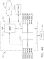
- the evacuation systems disclosed herein can be incorporated into a computer-implemented interactive surgical system, such as the system 100 ( FIG. 39 ) or the system 200 ( FIG. 47 ), for example.
- the computer-implemented surgical system 100 can include at least one hub 106 and a cloud 104.
- the hub 106 includes a smoke evacuation module 126. Operation of the smoke evacuation module 126 can be controlled by the hub 106 based on its situational awareness and/or feedback from the components thereof and/or based on information from the cloud 104.
- the computer-implemented surgical systems 100 and 200, as well as situational awareness therefor, are further described herein.
- Situational awareness encompasses the ability of some aspects of a surgical system to determine or infer information related to a surgical procedure from data received from databases and/or instruments.
- the information can include the type of procedure being undertaken, the type of tissue being operated on, or the body cavity that is the subject of the procedure.
- the surgical system can, for example, improve the manner in which it controls the modular devices (e.g. a smoke evacuation system) that are connected to it and provide contextualized information or suggestions to the clinician during the course of the surgical procedure.
- Situational awareness is further described herein and in U.S. Provisional Patent Application Serial No. 62/611,341 , entitled INTERACTIVE SURGICAL PLATFORM, filed December 28, 2017, which is incorporated by reference herein in its entirety.
- FIG. 5 is a schematic representation of an electrosurgical system 50300 including a processor 50308.
- the electrosurgical system 50300 is powered by an AC source 50302, which provides either 120 V or 240 V alternating current.
- the voltage supplied by the AC source 50302 is directed to an AC/DC converter 50304, which converts the 120 V or 240 V of alternating current to 360 V of direct current.
- the 360 V of direct current is then directed to a power converter 50306 (e.g., a buck converter).
- the power converter 50306 is a step-down DC to DC converter.
- the power converter 50306 is adapted to step-down the incoming 360 V to a desired level within a range between 0-150 V.
- the processor 50308 can be programmed to regulate various aspects, functions, and parameters of the electrosurgical system 50300. For instance, the processor 50308 can determine the desired output power level at an electrode tip 50334, which can be similar in many respects to the electrode tip 50034 in FIG. 2 and/or the electrode tip 51034 in FIG. 3 , for example, and direct the power converter 50306 to step-down the voltage to a specified level so as to provide the desired output power.
- the processor 50308 is coupled to a memory 50310 configured to store machine executable instructions to operate the electrosurgical system 50300 and/or subsystems thereof.
- DAC digital-to-analog converter
- the DAC 50312 is adapted to convert a digital code created by the processor 50308 to an analog signal (current, voltage, or electric charge) which governs the voltage step-down performed by the power converter 50306.
- the power converter 50306 steps-down the 360 V to a level that the processor 50308 has determined will provide the desired output power level, the stepped-down voltage is directed to the electrode tip 50334 to effectuate electrosurgical treatment of a patient's tissue and is then directed to a return or ground electrode 50335.
- a voltage sensor 50314 and a current sensor 50316 are adapted to detect the voltage and current present in the electrosurgical circuit and communicate the detected parameters to the processor 50308 so that the processor 50308 can determine whether to adjust the output power level.
- typical wave generators are adapted to maintain the selected settings throughout an electrosurgical procedure.
- the operational parameters of a generator can be optimized during a surgical procedure based on one or more inputs to the processor 5308, such as inputs from a surgical hub, cloud, and/or situational awareness module, for example, as further described herein.
- the processor 50308 is coupled to a communication device 50318 to communicate over a network.
- the communication device includes a transceiver 50320 configured to communicate over physical wires or wirelessly.
- the communication device 50318 may further include one or more additional transceivers.
- the transceivers may include, but are not limited to cellular modems, wireless mesh network transceivers, Wi-Fi® transceivers, low power wide area (LPWA) transceivers, and/or near field communications transceivers (NFC).
- the communication device 50318 may include or may be configured to communicate with a mobile telephone, a sensor system (e.g., environmental, position, motion, etc.) and/or a sensor network (wired and/or wireless), a computing system (e.g., a server, a workstation computer, a desktop computer, a laptop computer, a tablet computer (e.g., iPad®, GalaxyTab® and the like), an ultraportable computer, an ultramobile computer, a netbook computer and/or a subnotebook computer; etc.
- a coordinator node e.g., a coordinator node.
- the transceivers 50320 may be configured to receive serial transmit data via respective UARTs from the processor 50308, to modulate the serial transmit data onto an RF carrier to produce a transmit RF signal and to transmit the transmit RF signal via respective antennas.
- the transceiver(s) are further configured to receive a receive RF signal via respective antennas that includes an RF carrier modulated with serial receive data, to demodulate the receive RF signal to extract the serial receive data and to provide the serial receive data to respective UARTs for provision to the processor.
- Each RF signal has an associated carrier frequency and an associated channel bandwidth. The channel bandwidth is associated with the carrier frequency, the transmit data and/or the receive data.
- Each RF carrier frequency and channel bandwidth are related to the operating frequency range(s) of the transceiver(s) 50320.
- Each channel bandwidth is further related to the wireless communication standard and/or protocol with which the transceiver(s) 50320 may comply.
- each transceiver 50320 may correspond to an implementation of a selected wireless communication standard and/or protocol, e.g., IEEE 802.11 a/b/g/n for Wi-Fi® and/or IEEE 802.15.4 for wireless mesh networks using Zigbee routing.
- the processor 50308 is coupled to a sensing and intelligent controls device 50324 that is coupled to a smoke evacuator 50326.
- the smoke evacuator 50326 can include one or more sensors 50327, and can also include a pump and a pump motor controlled by a motor driver 50328.
- the motor driver 50328 is communicatively coupled to the processor 50308 and a pump motor in the smoke evacuator 50326.
- the sensing and intelligent controls device 50324 includes sensor algorithms 50321 and communication algorithms 50322 that facilitate communication between the smoke evacuator 50326 and other devices to adapt their control programs.
- the sensing and intelligent controls device 50324 is configured to evaluate extracted fluids, particulates, and gases via an evacuation conduit 50336 to improve smoke extraction efficiency and/or reduce device smoke output, for example, as further described herein.
- the sensing and intelligent controls device 50324 is communicatively coupled to one or more sensors 50327 in the smoke evacuator 50326, one or more internal sensors 50330 and/or one or more external sensors 50332 of the electrosurgical system 50300.
- a processor can be located within an evacuator housing of a surgical evacuation system.
- a processor 50408 and a memory 50410 therefor are positioned within an evacuator housing 50440 of a surgical evacuation system 50400.
- the processor 50408 is in signal communication with a motor driver 50428, various internal sensors 50430, a display 50442, the memory 50410, and a communication device 50418.
- the communication device 50418 is similar in many respects to the communication device 50318 described above with respect to FIG. 5 .
- the communication device 50418 can allow the processor 50408 in the surgical evacuation system 50400 to communicate with other devices within a surgical system.
- the communication device 50418 can allow wired and/or wireless communication to one or more external sensors 50432, one or more surgical devices 50444, one or more hubs 50448, one or more clouds 50446, and/or one or more additional surgical systems and/or tools.
- the surgical evacuation system 50400 of FIG. 6 can be incorporated into the electrosurgical system 50300 of FIG. 5 in certain instances.
- the surgical evacuation system 50400 also includes a pump 50450, including a pump motor 50451 thereof, an evacuation conduit 50436, and an exhaust 50452.
- Various pumps, evacuation conduits and exhausts are further described herein.
- the surgical evacuation system 50400 can also include a sensing and intelligent controls device, which can be similar in many respects to the sensing and intelligent controls device 50324, for example.
- a sensing and intelligent controls device can be in signal communication with the processor 50408 and/or one or more of the sensors 50430 and/or external sensors 50432.
- the electrosurgical system 50300 ( FIG. 5 ) and/or the surgical evacuation system 50400 ( FIG. 6 ) can be programmed to monitor one or more parameters of a surgical system and can affect a surgical function based on one or more algorithms stored in a memory in signal communication with the processor 50308 and/or 50408.
- Various exemplary aspects disclosed herein can be implemented by such algorithms, for example.
- a processor and sensor system such as the processors 50308 and 50408 and respective sensor systems in communication therewith ( FIGS. 5 and 6 ), are configured to sense the airflow through a vacuum source in order to adjust parameters of the smoke evacuation system and/or external devices and/or systems that are used in tandem with the smoke evacuation system, such as an electrosurgical system, energy device, and/or generator, for example.
- the sensor system may include multiple sensors positioned along the airflow path of the surgical evacuation system. The sensors can measure a pressure differential within the evacuation system, in order to detect a state or status of the system between the sensors.
- the system between two sensors can be a filter, and the pressure differential can be used to increase the speed of the pump motor as flow through the filter is reduced, in order to maintain a flow rate through the system.
- the system can be a fluid trap of the evacuation system, and the pressure differential can be used to determine an airflow path through the evacuation system.
- the system can be the inlet and outlet (or exhaust) of the evacuation system, and the pressure differential can be used to determine the maximum suction load in the evacuation system in order to maintain the maximum suction load below a threshold value.
- a processor and sensor system such as the processors 50308 and 50408 and respective sensor systems in communication therewith ( FIGS. 5 and 6 ), are configured to detect the ratio of an aerosol or carbonized particulate, i.e. smoke, in the fluid extracted from a surgical site.
- the sensing system may include a sensor that detects the size and/or the composition of particles, which is used to select an airflow path through the evacuation system.
- the evacuation system can include a first filtering path, or first filtering state, and a second filtering path, or second filtering state, which can have different properties.
- the first path includes only a particulate filter
- the second path includes both a fluid filter and the particulate filter.
- the first path includes a particulate filter
- the second path includes the particulate filter and a finer particulate filter arranged in series. Additional and/or alternative filtering paths are also envisioned.
- a processor and sensor system such as the processors 50308 and 50408 and respective sensor systems in communication therewith ( FIGS. 5 and 6 ), are configured to perform a chemical analysis on the particles evacuated from within the abdomen cavity of a patient.
- the sensing and intelligent controls device 50324 may sense the particle count and type in order to adjust the power level of the ultrasonic generator in order to induce the ultrasonic blade to produce less smoke.
- the sensor systems may include sensors for detecting the particle count, the temperature, the fluid content, and/or the contamination percentage of the evacuated fluid, and can communicate the detected property or properties to a generator in order to adjust its output.
- the smoke evacuator 50326 and/or the sensing and intelligent controls device 50324 therefor can be configured to adjust the evacuation flow rate and/or the pump's motor speed and, at a predefined particulate level, may operably affect the output power or waveform of the generator to lower the smoke generated by the end effector.
- a processor and sensor system such as the processors 50308 and 50408 and respective sensor systems therewith ( FIGS. 5 and 6 ), are configured to evaluate particle count and contamination in the operating room by evaluating one or more properties in the ambient air and/or the exhaust from the evacuator housing.
- the particle count and/or the air quality can be displayed on the smoke evacuation system, such as on the evacuator housing, for example, in order to communicate the information to a clinician and/or to establish the effectiveness of the smoke evacuation system and filter(s) thereof.
- a processor such as the processor 50308 or the processor 50408 ( FIGS. 5 and 6 ), for example, is configured to compare a sample rate image obtained from an endoscope to the evacuator particle count from the sensing system (e.g. the sensing and intelligent controls device 50324) in order to determine a correlation and/or to adjust the rate of the pump's revolutions-per-minute (RPM).
- the activation of the generator can be communicated to the smoke evacuator such that an anticipated, required rate of smoke evacuation can be implemented.
- the generator activation can be communicated to the surgical evacuation system through a surgical hub, cloud communication system, and/or direct connection, for example.
- sensor systems and algorithms for a smoke evacuation system can be configured to control the smoke evacuator, and can adapt motor parameters thereof to adjust the filtering efficiency of the smoke evacuator based on the needs of the surgical field at a given time.
- an adaptive airflow pump speed algorithm is provided to automatically change the motor pump speed based on the sensed particulate into the inlet of the smoke evacuator and/or out of the outlet or exhaust of the smoke evacuator.
- the sensing and intelligent controls device 50324 FIG. 5
- the airflow through the evacuation system can be scalable based on the smoke into the evacuation system and/or a lack of filtered particles out of the smoke evacuation system.
- the auto-mode speed can provide automatic sensing and compensation for laparoscopic mode in certain instances.
- the evacuation system can include an electrical and communication architecture (see, e.g. FIGS. 5 and 6 ) that provides data collection and communication features, in order to improve interactivity with a surgical hub and a cloud.
- a surgical evacuation system and/or processor therefor such as the processor 50308 ( FIG. 5 ) and the processor 50408 ( FIG. 6 ), for example, can include a segmented control circuit that is energized in a staged method to check for errors, shorts, and/or safety checks of the system.
- the segmented control circuit may also be configured to have a portion energized and a portion not energized until the energized portion performs a first function.
- the segmented control circuit can include circuit elements to identify and display status updates to the user of attached components.
- the segmented control circuit also includes circuit elements for running the motor in a first state, in which the motor is activated by the user, and in a second state, in which the motor has not been activated by the user but runs the pump in a quieter manner and at a slower rate.
- a segmented control circuit can allow the smoke evacuator to be energized in stages, for example.
- the electrical and communication architecture for the evacuation system can also provide interconnectivity of the smoke evacuator with other components within the surgical hub for interactions, as well as communication of data with a cloud.
- Communication of surgical evacuation system parameters to a surgical hub and/or cloud can be provided to affect the output or operation of other attached devices.
- the parameters can be operational or sensed. Operational parameters include airflow, pressure differentials, and air quality. Sensed parameters include particulate concentration, aerosol percentage, and chemical analysis.
- the evacuation system such as the surgical evacuation system 50400, for example, can also include an enclosure and replaceable components, controls, and a display. Circuit elements are provided for communicating the security identification (ID) between such replaceable components. For example, communication between a filter and the smoke evacuation electronics can be provided to verify authenticity, remaining life of the component, to update parameters in the component, to log errors, and/or to limit the number and/or the type of components that can be identified by the system.
- the communication circuit can authenticate features for enabling and/or disabling of configuration parameters.
- the communication circuit can employ encryption and/or error handling schemes to manage security and proprietary relationships between the component and the smoke evacuation electronics. Disposable/re-useable components are included in certain instances.
- the evacuation systems can provide fluid management and extraction filters and airflow configurations.
- a surgical evacuation system including a fluid capture mechanism is provided where the fluid capture mechanism has a first and a second set of extraction or airflow control features, which are in series with each other to extract large and small fluid droplets, respectively.
- the airflow path can contain a recirculation channel or secondary fluid channel back to the primary reservoir from downstream of the exhaust port of the main fluid management chamber.
- an advanced pad can be coupled to the electrosurgical system.
- the ground electrode 50335 of the electrosurgical system 50300 FIG. 5
- the capacitive coupling return path pad can have small separable array elements, which can be used to sense nerve control signals and/or movement of select anatomic locations, in order to detect the proximity of the monopolar tip to a nerve bundle.
- An electrosurgical system can includes a signal generator, an electrosurgical instrument, a return electrode, and a surgical evacuation system.
- the generator may be an RF wave generator that produces RF electrical energy.
- Connected to the electrosurgical instrument is a utility conduit.
- the utility conduit includes a cable that communicates electrical energy from the signal generator to the electrosurgical instrument.
- the utility conduit also includes a vacuum hose that conveys captured/collected smoke and/or fluid away from a surgical site.
- FIG. 7 Such an exemplary electrosurgical system 50601 is shown in FIG. 7 . More specifically, the electrosurgical system 50601 includes a generator 50640, an electrosurgical instrument 50630, a return electrode 50646, and an evacuation system 50600.
- the electrosurgical instrument 50630 includes a handle 50632 and a distal conduit opening 50634 that is fluidically coupled to a suction hose 50636 of the evacuation system 50600.
- the electrosurgical instrument 50630 also includes an electrode that is powered by the generator 50640.
- a first electrical connection 50642, e.g., a wire extends from the electrosurgical instrument 50630 to the generator 50640.
- a second electrical connection 50644, e.g., a wire extends from the electrosurgical instrument 50630 to electrode, i.e., the return electrode 50646.
- the electrosurgical instrument 50630 can be a bipolar electrosurgical instrument.
- the distal conduit opening 50634 on the electrosurgical instrument 50630 is fluidically coupled to the suction hose 50636 that extends to a filter end cap 50603 of a filter that is installed in an evacuator housing 50618 of the evacuation system 50600.
- the distal conduit opening 50634 for the evacuation system 50600 can be on a handpiece or tool that is separate from the electrosurgical instrument 50630.
- the evacuation system 50600 can include a surgical tool that is not coupled to the generator 50640 and/or does not include tissue-energizing surfaces.
- the distal conduit opening 50634 for the evacuation system 50600 can be releasably attached to an electrosurgical tool.
- the evacuation system 50600 can include a clip-on or snap-on conduit terminating at a distal conduit opening, which can be releasably attached to a surgical tool (see, e.g., FIG. 3 ).
- the electrosurgical instrument 50630 is configured to deliver electrical energy to target tissue of a patient to cut the tissue and/or cauterize blood vessels within and/or near the target tissue, as described herein. Specifically, an electrical discharge is provided by the electrode tip to the patient in order to cause heating of cellular matter of the patient that is in close contact with or adjacent to electrode tip. The tissue heating takes place at an appropriately high temperature to allow the electrosurgical instrument 50630 to be used to perform electrosurgery.
- the return electrode 50646 is either applied to or placed in close proximity to the patient (depending on the type of return electrode), in order to complete the circuit and provide a return electrical path to the generator 50640 for energy that passes into the patient's body.
- the evacuation conduit opening 50634 is near the electrode tip, the evacuation system 50600 is configured to capture the smoke that is released during a surgical procedure. Vacuum suction may draw the smoke into the conduit opening 50634, through the electrosurgical instrument 50630, and into the suction hose 50636 toward the evacuator housing 50618 of the evacuation system 50600.
- the evacuator housing 50618 of the evacuation system 50600 ( FIG. 7 ) is depicted.
- the evacuator housing 50618 includes a socket 50620 that is dimensioned and structured to receive a filter.
- the evacuator housing 50618 can completely or partially encompass the internal components of the evacuator housing 50618.
- the socket 50620 includes a first receptacle 50622 and a second receptacle 50624.
- a transition surface 50626 extends between the first receptacle 50622 and the second receptacle 50624.
- the socket 50620 is depicted along a cross sectional plane indicated in FIG. 8 .
- the socket 50620 includes a first end 50621 that is open to receive a filter and a second end 50623 in communication with a flow path 50699 through the evacuator housing 50618.
- a filter 50670 FIGS. 10 and 11 ) may be removably positioned with the socket 50620.
- the filter 50670 can be inserted and removed from the first end 50621 of the socket 50620.
- the second receptacle 50624 is configured to receive a connection nipple of the filter 50670.
- Surgical evacuation systems often use filters to remove unwanted pollutants from the smoke before the smoke is released as exhaust.
- the filters can be replaceable.
- the reader will appreciate that the filter 50670 depicted in FIGS. 10 and 11 can be employed in various evacuation systems disclosed herein.
- the filter 50670 can be a replaceable and/or disposable filter.
- the filter 50670 includes a front cap 50672, a back cap 50674, and a filter body 50676 disposed therebetween.
- the front cap 50672 includes a filter inlet 50678, which, in certain instances, is configured to receive smoke directly from the suction hose 50636 ( FIG. 7 ) or other smoke source.
- the front cap 50672 can be replaced by a fluid trap (e.g. the fluid trap 50760 depicted in FIGS. 14-17 ) that directs the smoke directly from the smoke source, and after removing at least a portion of the fluid therefrom, passes the partially processed smoke into the filter body 50676 for further processing.
- the filter inlet 50678 can be configured to receive smoke via a fluid trap exhaust port, such as a port 50766 in a fluid trap 50760 ( FIGS. 14-17 ) to communicate partially processed smoke into the filter 50670.
- the smoke can be filtered by components housed within the filter body 50676.
- the filtered smoke can then exit the filter 50670 through a filter exhaust 50680 defined in the back cap 50674 of the filter 50670.
- suction generated in the evacuator housing 50618 of the evacuation system 50600 can be communicated to the filter 50670 through the filter exhaust 50680 to pull the smoke through the internal filtering components of the filter 50670.
- a filter often includes a particulate filter and a charcoal filter.
- the particulate filter can be a high-efficiency particulate air (HEPA) filter or an ultra-low penetration air (ULPA) filter, for example.
- HEPA high-efficiency particulate air
- ULPA ultra-low penetration air
- the ULPA filtration utilizes a depth filter that is similar to a maze.
- the particulate can be filtered using at least one of the following methods: direct interception (in which particles over 1.0 micron are captured because they are too large to pass through the fibers of the media filter), inertial impaction (in which particles between 0.5 and 1.0 micron collide with the fibers and remain there, and diffusional interception (in which particles less than 0.5 micron are captured by the effect of Brownian random thermal motion as the particles "search out” fibers and adhere to them).
- the charcoal filter is configured to remove toxic gases and/or odor generated by the surgical smoke.
- the charcoal can be "activated” meaning it has been treated with a heating process to expose the active absorption sites.
- the charcoal can be from activated virgin coconut shells, for example.
- the filter 50670 includes a coarse media filter layer 50684 followed by a fine particulate filter layer 50686.
- the filter 50670 may consist of a single type of filter.
- the filter 50670 can include more than two filter layers and/or more than two different types of filter layers.
- the smoke is drawn through a carbon reservoir 50688 in the filter 50670 to remove gaseous contaminants within the smoke, such as volatile organic compounds, for example.
- the carbon reservoir 50688 can comprise a charcoal filter.
- the filtered smoke which is now substantially free of particulate matter and gaseous contaminants, is drawn through the filter exhaust 50680 and into the evacuation system 50600 for further processing and/or elimination.
- the filter 50670 includes a plurality of dams between components of the filter body 50676.
- a first dam 50690 is positioned intermediate the filter inlet 50678 ( FIG. 10 ) and a first particulate filter, such as the coarse media filter 50684, for example.
- a second dam 50692 is positioned intermediate a second particulate filter, such as the fine particulate filter 50686, for example, and the carbon reservoir 50688.
- a third dam 50694 is positioned intermediate the carbon reservoir 50688 and the filter exhaust 50680.
- the dams 50690, 50692, and 50694 can comprise a gasket or O-ring, which is configured to prevent movement of the components within the filter body 50676.
- the size and shape of the dams 50690, 50692, and 50694 can be selected to prevent distention of the filter components in the direction of the applied suction.
- the coarse media filter 50684 can include a low-air-resistant filter material, such as fiberglass, polyester, and/or pleated filters that are configured to remove a majority of particulate matter larger than 10 ⁇ m, for example.
- this includes filters that remove at least 85% of particulate matter larger than 10 ⁇ m, greater than 90% of particulate matter larger than 10 ⁇ m, greater than 95% of particular matter larger than 10 ⁇ m, greater than 99% of particular matter larger than 10 ⁇ m, greater than 99.9% particulate matter larger than 10 ⁇ m, or greater than 99.99% particulate matter larger than 10 ⁇ m.
- the coarse media filter 50684 can include a low-air-resistant filter that removes the majority of particulate matter greater than 1 ⁇ m.
- this includes filters that remove at least 85% particulate matter larger than 1 ⁇ m, greater than 90% of particulate matter larger than 1 ⁇ m, greater than 95% of particular matter larger than 1 ⁇ m, greater than 99% of particular matter larger than 1 ⁇ m, greater than 99.9% particulate matter larger than 1 ⁇ m, or greater than 99.99% particulate matter larger than 1 ⁇ m.
- the fine particulate filter 50686 can include any filter of higher efficiency than the coarse media filter 50684. This includes, for example, filters that are capable of filtering a higher percentage of the same sized particles as the coarse media filter 50684 and/or capable of filtering smaller sized particles than the coarse media filter 50684.
- the fine particulate filter 50686 can include a HEPA filter or an ULPA filter. Additionally or alternatively, the fine particulate filter 50686 can be pleated to increase the surface area thereof.
- the coarse media filter 50684 includes a pleated HEPA filter and the fine particulate filter 50686 includes a pleated ULPA filter.
- the carbon reservoir 50688 is bounded by porous dividers 50696 and 50698 disposed between the intermediate and terminal dams 50692 and 50694, respectively.
- the porous dividers 50696 and 50698 are rigid and/or inflexible and define a constant spatial volume for the carbon reservoir 50688.
- the carbon reservoir 50688 can include additional sorbents that act cumulatively with or independently from the carbon particles to remove gaseous pollutants.
- the additional sorbents can include, for example, sorbents such as magnesium oxide and/or copper oxide, for example, which can act to adsorb gaseous pollutants such as carbon monoxide, ethylene oxide, and/or ozone, for example.
- additional sorbents are dispersed throughout the reservoir 50688 and/or are positioned in distinct layers above, below, or within the reservoir 50688.
- the evacuation system 50500 includes the pump 50506 within the evacuator housing 50518.
- the evacuation system 50600 depicted in FIG. 7 can include a pump located in the evacuator housing 50618, which can generate suction to pull smoke from the surgical site, through the suction hose 50636 and through the filter 50670 ( FIGS. 10 and 11 ).
- the pump can create a pressure differential within the evacuator housing 50618 that causes the smoke to travel into the filter 50670 and out an exhaust mechanism (e.g. exhaust mechanism 50520 in FIG. 4 ) at the outlet of the flow path.
- the filter 50670 is configured to extract harmful, foul, or otherwise unwanted particulates from the smoke.
- the pump can be disposed in-line with the flow path through the evacuator housing 50618 such that the gas flowing through the evacuator housing 50618 enters the pump at one end and exits the pump at the other end.
- the pump can provide a sealed positive displacement flow path.
- the pump can produce the sealed positive displacement flow path by trapping (sealing) a first volume of gas and decreasing that volume to a second smaller volume as the gas moves through the pump. Decreasing the volume of the trapped gas increases the pressure of the gas.
- the second pressurized volume of gas can be released from the pump at a pump outlet.
- the pump can be a compressor.
- the pump can comprise a hybrid regenerative blower, a claw pump, a lobe compressor, and/or a scroll compressor.
- Positive displacement compressors can provide improved compression ratios and operating pressures while limiting vibration and noise generated by the evacuation system 50600.
- the evacuation system 50600 can include a fan for moving fluid therethrough.
- FIG. 12 An example of a positive displacement compressor, e.g. a scroll compressor pump 50650, is depicted in FIG. 12 .
- the scroll compressor pump 50650 includes a stator scroll 50652 and a moving scroll 50654.
- the stator scroll 50652 can be fixed in position while the moving scroll 50654 orbits eccentrically.
- the moving scroll 50654 can orbit eccentrically such that it rotates about the central longitudinal axis of the stator scroll 50652.
- the central longitudinal axes of the stator scroll 50652 and the moving scroll 50654 extend perpendicular to the viewing plane of the scrolls 50652, 50654.
- the stator scroll 50652 and the moving scroll 50654 are interleaved with each other to form discrete sealed compression chambers 50656.
- a gas can enter the scroll compressor pump 50650 at an inlet 50658.
- the compression chamber 50656 is configured to move a discrete volume of gas along the spiral contour of the scrolls 50652 and 50654 toward the center of the scroll compressor pump 50650.
- the compression chamber 50656 defines a sealed space in which the gas resides.
- the compression chamber 50656 decreases in volume. This decrease in volume increases the pressure of the gas inside the compression chamber 50656.
- the gas inside the sealed compression chamber 50656 is trapped while the volume decreases, thus pressurizing the gas. Once the pressurized gas reaches the center of the scroll compressor pump 50650, the pressurized gas is released through an outlet 50659.
- the evacuation system 50700 can be similar in many respects to the evacuation system 50600 ( FIG. 7 ).
- the evacuation system 50700 includes the evacuator housing 50618 and the suction hose 50636.
- the evacuation system 50600 is configured to produce suction and thereby draw smoke from the distal end of the suction hose 50636 into the evacuator housing 50618 for processing.
- the suction hose 50636 is not connected to the evacuator housing 50618 through the filter end cap 50603 in FIG. 13 .
- suction hose 50636 is connected to the evacuator housing 50618 through the fluid trap 50760.
- a filter similar to the filter 50670 can be positioned within the socket of the evacuator housing 50618 behind the fluid trap 50760.
- the fluid trap 50760 is a first processing point that extracts and retains at least a portion of the fluid (e.g. liquid) from the smoke before relaying the partially-processed smoke to the evacuation system 50700 for further processing and filtration.
- the evacuation system 50700 is configured to process, filter, and otherwise clean the smoke to reduce or eliminate unpleasant odors or other problems associated with smoke generation in the surgical theater (or other operating environment), as described herein.
- the fluid trap 50760 can, among other things, increase the efficiency of the evacuation system 50700 and/or increase the life of filters associated therewith, in certain instances.
- the fluid trap 50760 is depicted detached from the evacuator housing 50618 ( FIG. 13 ).
- the fluid trap 50760 includes an inlet port 50762 defined in a front cover or surface 50764 of the fluid trap 50760.
- the inlet port 50762 can be configured to releasably receive the suction hose 50636 ( FIG. 13 ).
- an end of the suction hose 50636 can be inserted at least partially within the inlet port 50762 and can be secured with an interference fit therebetween.
- the interference fit can be a fluid tight and/or airtight fit so that substantially all of the smoke passing through the suction hose 50636 is transferred into the fluid trap 50760.
- other mechanisms for coupling or joining the suction hose 50636 to the inlet port 50762 can be employed such as a latch-based compression fitting, an O-ring, threadably coupling the suction hose 50636 with the inlet port 50762, for example, and/or other coupling mechanisms.
- a fluid tight and/or airtight fit between the suction hose 50636 and the fluid trap 50760 is configured to prevent fluids and/or other materials in the evacuated smoke from leaking at or near the junction of these components.
- the suction hose 50636 can be associated with the inlet port 50762 through an intermediate coupling device, such as an O-ring and/or adaptor, for example, to further ensure an airtight and/or fluid tight connection between the suction hose 50636 and the fluid trap 50760.
- the fluid trap 50760 includes the exhaust port 50766.
- the exhaust port extends away from a rear cover or surface 50768 of the fluid trap 50760.
- the exhaust port 50766 defines an open channel between an interior chamber 50770 of the fluid trap 50760 and the exterior environment.
- the exhaust port 50766 is sized and shaped to tightly associate with a surgical evacuation system or components thereof.
- the exhaust port 50766 can be sized and shaped to associate with and communicate at least partially processed smoke from the fluid trap 50760 to a filter housed within an evacuator housing 50618 ( FIG. 13 ).
- the exhaust port 50766 can extend away from the front plate, a top surface, or a side surface of the fluid trap 50760.
- the exhaust port 50766 includes a membrane, which spaces the exhaust port 50766 apart from the evacuator housing 50618.
- a membrane can act to prevent water or other liquid collected in the fluid trap 50760 from being passed through the exhaust port 50766 and into the evacuator housing 50618 while permitting air, water and/or vapor to freely pass into the evacuator housing 50618.
- a high flow rate microporous polytetrafluoroethylene (PTFE) can be positioned downstream of the exhaust port 50766 and upstream of a pump to protect the pump or other components of the evacuation system 50700 from damage and/or contamination.
- the fluid trap 50760 also includes a gripping region 50772, which is positioned and dimensioned to assist a user in handling the fluid trap 50760 and/or connecting the fluid trap 50760 with the suction hose 50636 and/or the evacuator housing 50618.
- the gripping region 50772 is depicted as being an elongate recess; however, the reader will readily appreciate that the gripping region 50772 may include at least one recess, groove, protrusion, tassel, and/or ring, for example, which can be sized and shaped to accommodate a user's digits or to otherwise provide a gripping surface.
- the interior chamber 50770 of the fluid trap 50760 is depicted.
- the relative positioning of the inlet port 50762 and the exhaust port 50766 is configured to promote the extraction and the retention of fluid from the smoke as it passes into the fluid trap 50760.
- the inlet port 50762 can comprise a notched cylindrical shape, which can direct the smoke and the accompanying fluid towards a fluid reservoir 50774 of the fluid trap 50760 or otherwise directionally away from the exhaust port 50766.
- An example of such a fluid flow is depicted with arrows A, B, C, D, and E in FIG. 17 .
- the smoke entering the inlet port 50762 is initially directed primarily downward into the fluid reservoir 50774 of the fluid trap 50760 (illustrated by the arrows B).
- the directional flow of smoke through the fluid trap 50760 can ensure that liquids within the smoke are extracted and retained within the lower portion (e.g. the fluid reservoir 50774) of the fluid trap 50760. Furthermore, the relative positioning of the exhaust port 50766 vertically above the inlet port 50762 when the fluid trap 50760 is in an upright position is configured to discourage liquid from inadvertently being carried through the exhaust port 50766 by the flow of smoke while not substantially hindering fluid flow into and out of the fluid trap 50760. Additionally, in certain instances, the configuration of the inlet port 50762 and the outlet port 50766 and/or the size and shape of the fluid trap 50760 itself, can enable the fluid trap 50760 to be spill resistant.
- an evacuation system can include a plurality of sensors and intelligent controls, as further described herein with respect to FIGS. 5 and 6 , for example.
- an evacuation system can include one or more temperatures sensors, one or more fluid detection sensors, one or more pressure sensors, one or more particle sensors, and/or one or more chemical sensors.
- a temperature sensor can be positioned to detect the temperature of a fluid at the surgical site, moving through a surgical evacuation system, and/or being exhaust into a surgical theater from a surgical evacuation system.
- a pressure sensor can be positioned to detect a pressure within the evacuation system, such as within the evacuator housing.
- a pressure sensor can be positioned upstream of the filter, between the filter and the pump, and/or downstream of the pump.
- a pressure sensor can be positioned to detect a pressure in the ambient environment outside of the evacuation system.
- a particle sensor can be positioned to detect particles within the evacuation system, such as within the evacuator housing.
- a particle sensor can be upstream of the filter, between the filter and the pump, and/or downstream of the pump, for example.
- a particle sensor can be positioned to detect particles in the ambient environment in order to determine the air quality in the surgical theater, for example.
- FIG. 18 An evacuator housing 50818 for an evacuation system 50800 is schematically depicted in FIG. 18 .
- the evacuator housing 50818 can be similar in many respects to the evacuator housings 50018 and/or 50618, for example, and/or can be incorporated into various evacuation systems disclosed herein.
- the evacuator housing 50818 includes numerous sensors, which are further described herein. The reader will appreciate that certain evacuator housings may not include each sensor depicted in FIG. 18 and/or may include additional sensor(s). Similar to the evacuator housings 50018 and 50618 disclosed herein, the evacuator housing 50818 of FIG. 18 includes an inlet 50822 and an outlet 50824. A fluid trap 50860, a filter 50870, and a pump 50806 are sequentially aligned along a flow path 50804 through the evacuator housing 50818 between the inlet 50822 and the outlet 50824.
- An evacuator housing can include modular and/or replaceable components, as further described herein.
- an evacuator housing can include a socket or a receptacle 50871 dimensioned to receive a modular fluid trap and/or a replaceable filter.
- a fluid trap and a filter can be incorporated into a single interchangeable module 50859, as depicted in FIG. 18 .
- the fluid trap 50860 and the filter 50870 form the interchangeable module 50859, which can be modular and/or replaceable, and can be removably installed in the receptacle 50871 in the evacuator housing 50818.
- the fluid trap 50860 and the filter 50870 can be separate and distinct modular components, which can be assembled together and/or separately installed in the evacuator housing 50818.
- the evacuator housing 50818 includes a plurality of sensors for detecting various parameters therein and/or parameters of the ambient environment. Additionally or alternatively, one or more modular components installed in the evacuator housing 50818 can include one or more sensors.
- the interchangeable module 50859 includes a plurality of sensors for detecting various parameters therein.
- the evacuator housing 50818 and/or a modular component(s) compatible with the evacuator housing 50818 can include a processor, such as the processor 50308 and 50408 ( FIGS. 5 and 6 , respectively), which is configured to receive inputs from one or more sensors and/or to communicate outputs to one more systems and/or drivers.
- a processor such as the processor 50308 and 50408 ( FIGS. 5 and 6 , respectively)
- smoke from a surgical site can be drawn into the inlet 50822 to the evacuator housing 50818 via the fluid trap 50860.
- the flow path 50804 through the evacuator housing 50818 in FIG. 18 can comprise a sealed conduit or tube 50805 extending between the various in-line components.
- the smoke can flow past a fluid detection sensor 50830 and a chemical sensor 50832 to a diverter valve 50834, which is further described herein.
- a fluid detection sensor such as the sensor 50830, can detect fluid particles in the smoke.
- the fluid detection sensor 50830 can be a continuity sensor.
- the fluid detection sensor 50830 can include two spaced-apart electrodes and a sensor for detecting the degree of continuity therebetween. When no fluid is present, the continuity can be zero, or substantially zero, for example.
- the chemical sensor 50832 can detect the chemical properties of the smoke.
- fluid can be directed into a condenser 50835 of the fluid trap 50860 and the smoke can continue toward the filter 50870.
- Baffles 50864 are positioned within the condenser 50835 to facilitate the condensation of fluid droplets from the smoke into a reservoir in the fluid trap 50860.
- a fluid detection sensor 50836 can ensure any fluid in the evacuator housing is entirely, or at least substantially, captured within the fluid trap 50860.
- the smoke can then be directed to flow into the filter 50870 of the interchangeable module 50859.
- the smoke can flow past a particle sensor 50838 and a pressure sensor 50840.
- the particle sensor 50838 can comprise a laser particle counter, as further described herein.
- the smoke can be filtered via a pleated ultra-low penetration air (ULPA) filter 50842 and a charcoal filter 50844, as depicted in FIG. 18 .
- ULPA ultra-low penetration air
- the filtered smoke can flow past a pressure sensor 50846 and can then continue along the flow path 50804 within the evacuator housing 50818 toward the pump 50806.
- the filtered smoke can flow past a particle sensor 50848 and a pressure sensor 50850 at the outlet to the evacuator housing 50818.
- the particle sensor 50848 can comprise a laser particle counter, as further described herein.
- the evacuator housing 50818 in FIG. 18 also includes an air quality particle sensor 50852 and an ambient pressure sensor 50854 to detect various properties of the ambient environment, such as the environment within the surgical theater.
- the air quality particle sensor, or external/ambient air particle sensor, 50852 can comprise a laser particle counter in at least one form.
- the various sensors depicted in FIG. 18 are further described herein.
- alternative sensing means can be utilized in the smoke evacuation systems disclosed herein.
- alternative sensors for counting particles and/or determining particulate concentration in a fluid are further disclosed herein.
- the fluid trap 50860 depicted in FIG. 18 can be configured to prevent spillage and/or leakage of the captured fluid.
- the geometry of the fluid trap 50860 can be selected to prevent the captured fluid from spilling and/or leaking.
- the fluid trap 50860 can include baffles and/or splatter screens, such as the screen 50862, for preventing the captured fluid from splashing out of the fluid trap 50860.
- the fluid trap 50860 can include sensors for detecting the volume of fluid within the fluid trap and/or determining if the fluid trap 50860 is filled to capacity.
- the fluid trap 50860 may include a valve for empty the fluid therefrom.
- the filter 50870 can include additional and/or fewer filtering levels.
- the filter 50870 can include one or more filtering layers selected from the following group of filters: a course media filter, a fine media filter, and a sorbent-based filter.
- the course media filter can be a low-air-resistant filter, which can be comprised of fiberglass, polyester, and/or pleated filters, for example.
- the fine media filter can be a high efficiency particulate air (HEPA) filter and/or ULPA filter.
- the sorbent-based filter can be an activated-carbon filter, for example.
- the pump 50806 depicted in FIG. 18 can be replaced by and/or used in combination with another compressor and/or pump, such as a hybrid regenerative blower, a claw pump, and/or a lobe compressor, for example.
- a hybrid regenerative blower such as a hybrid regenerative blower, a claw pump, and/or a lobe compressor, for example.
- a lobe compressor such as a hybrid regenerative blower, a claw pump, and/or a lobe compressor, for example.
- various alternative pumping arrangements and geometries can be employed to generate suction within the flow path 50804 to draw smoke into the evacuator housing 50818.
- the various sensors in an evacuation system can communicate with a processor.
- the processor can be incorporated into the evacuation system and/or can be a component of another surgical instrument and/or a surgical hub.
- Various processors are further described herein.
- An on-board processor can be configured to adjust one or more operational parameters of the evacuator system (e.g. a motor for the pump 50806) based on input from the sensor(s). Additionally or alternatively, an on-board processor can be configured to adjust one or more operational parameters of another device, such as an electrosurgical tool and/or imaging device based on input from the sensor(s).
- FIG. 19 another evacuator housing 50918 for an evacuation system 50900 is depicted.
- the evacuator housing 50918 in FIG. 19 can be similar in many respects to the evacuator housing 50818 in FIG. 18 .
- the evacuator housing 50918 defines a flow path 50904 between an inlet 50922 to the evacuator housing 50918 and an outlet 50924 to the evacuator housing 50918.
- a fluid trap 50960, a filter 50970, and a pump 50906 are sequentially arranged.
- the evacuator housing 50918 can include a socket or a receptacle 50971 dimensioned to receive a modular fluid trap and/or a replaceable filter, similar to the receptacle 50871, for example.
- a diverter valve 50934 fluid can be directed into a condenser 50935 of the fluid trap 50960 and the smoke can continue toward the filter 50970.
- the fluid trap 50960 can include baffles, such as the baffles 50964, and/or splatter screens, such as the screen 50962, for example, for preventing the captured fluid from splashing out of the fluid trap 50960.
- the filter 50970 includes a pleated ultra-low penetration air (ULPA) filter 50942 and a charcoal filter 50944.
- ULPA ultra-low penetration air
- a sealed conduit or tube 50905 extends between the various in-line components.
- the evacuator housing 50918 also includes the sensors 50830, 50832, 50836, 50838, 50840, 50846, 50848, 50850, 50852, and 50854 which are further described herein and shown in FIG. 18 and FIG. 19 .
- the evacuator housing 50918 also includes a centrifugal blower arrangement 50980 and a recirculating valve 50990.
- the recirculating valve 50990 can selectively open and close to recirculate fluid through the fluid trap 50960. For example, if the fluid detection sensor 50836 detects a fluid, the recirculating valve 50990 can be opened such that the fluid is directed back away from the filter 50970 and back into the fluid trap 50960. If the fluid detection sensor 50836 does not detect a fluid, the valve 50990 can be closed such that the smoke is directed into the filter 50970. When fluid is recirculated via the recirculating valve 50990, the fluid can be drawn through a recirculation conduit 50982.
- the centrifugal blower arrangement 50980 is engaged with the recirculation conduit 50982 to generate a recirculating suction force in the recirculation conduit 50982. More specifically, when the recirculating valve 50990 is open and the pump 50906 is activated, the suction force generated by the pump 50906 downstream of the filter 50970 can generate rotation of the first centrifugal blower, or squirrel cage, 50984, which can be transferred to the second centrifugal blower, or squirrel cage, 50986, which draws the recirculated fluid through the recirculating valve 50990 and into the fluid trap 50960.
- control schematics of FIGS. 5 and 6 can be utilized with the various sensor systems and evacuator housings of FIGS. 18 and 19 .
- Smoke evacuated from a surgical site can include liquids, aerosols, and/or gases, and/or can include material of different chemical and/or physical properties, such as particulate matter and particles of different sizes and/or densities, for example.
- the different types of materials evacuated from a surgical site can affect the efficiency of the surgical evacuation system and the pump thereof. Moreover, certain types of material can require the pump to draw excessive power and/or can risk damaging the motor for the pump.
- the power supplied to the pump can be modulated to control the flowrate of smoke through the evacuation system based on input from one or more sensors along the flow path.
- Output from the sensors can be indicative of a state or quality of the smoke evacuation system and/or one or more properties of the evacuated smoke such as the type(s) and ratios of matter, chemical properties, density, and/or size of particulates, for example.
- a pressure differential between two pressure sensors in the evacuation system can indicate the state of the region therebetween such as the state of a filter, a fluid trap, and/or the overall system, for example.
- an operational parameter of the motor for the pump can be adjusted by changing the current supplied to the motor and/or the duty cycle, which is configured to change the motor speed.
- the efficiency of the filter can be improved and/or the motor can be protected from burnout.
- a surgical evacuation system can include one or more particle counters, or particle sensors, for detecting the size and/or concentration of particulate within the smoke.
- particle sensors 50838 and 50848 are depicted.
- a particle sensor can be an optical sensor, a laser sensor, a photoelectric sensor, an ionization sensor, an electrostatic sensor, and/or combinations thereof.
- Various particle sensors are further described herein.
- the speed of the motor and, thus, the speed of the pump can be adjusted based on the particulate concentration detected by the one or more particle sensors in a surgical evacuation system. For example, when the particle sensor(s) detects an increased concentration of particulate in the flow path, which can correspond to an increased quantity of smoke in the flow path, the speed of the motor can be increased to increase the speed of the pump and to draw more fluid into the smoke evacuation system from the surgical site. Similarly, when the particle sensor(s) detects a decreased concentration of particulate in the flow path, which can correspond to a decreased quantity of smoke in the flow path, the speed of the motor can be decreased to decrease the speed of the pump and to reduce suction from the surgical site. Additional and alternative adjustment algorithms for the surgical evacuation system are further described herein. Moreover, in certain instances, based on the sensor data from the smoke evacuation system, a generator in the surgical system can be controlled to adjust the amount of smoke generated at the surgical site, as further described herein.
- the system can include one or more sensors for detecting the particulate concentration in the ambient room, for example, in the operating room or surgical theater.
- the air quality particle sensor 50852 is installed on an external surface of the evacuator housing 50818. Alternative locations for the air quality particle sensor 50852 are also envisioned.
- a particle sensor can be positioned downstream of the filter and, in certain instances, can be positioned at or near the outlet of the filter.
- the particle sensor 50848 is positioned downstream of the filter 50870 and the pump 50806 in the smoke evacuation system 50800 and is positioned downstream of the filter 50970 and the pump 50906 in the smoke evacuation system 50900. Because the particle sensor 50848 is positioned downstream of the filter(s) 50870, 50970, the particle sensor is configured to confirm that the filter(s) 50870, 50970 have removed sufficient particulate from the smoke.
- such a sensor can be adjacent to the exhaust outlet 50824, 50924 of the evacuator housing 50818, 50918, respectively.
- an electrostatic particle sensor can be utilized.
- the exhaust outlet 50824, 50924 can include an electrostatic particulate sensor that the exhaust flows past downstream of the filtration system and prior to being exhaust into the surgical theater.
- the particulate concentration detected by one or more sensors of the surgical evacuation system can be communicated to a clinician in a number of different ways.
- the evacuator housing 50818, 50918 and/or the evacuation device e.g. the electrosurgical instrument 50032 in FIG. 2
- the evacuation device can include an indicator, such as one or more lights and/or display screens.
- an LED on the evacuator housing 50818, 50819 may change color (e.g. from blue to red) depending on the volume of particulate detected by the sensor(s).
- the indicator can include an alarm or warning, which can be tactile, auditory, and/or visual, for example.
- the clinician(s) in the surgical theater can be notified by the indicator(s).
- a surgical evacuation system can include an optical sensor.
- the optical sensor can include an electronic sensor that coverts light, or a change in the light, into an electronic signal.
- the optical sensor can utilize a light scattering method to detect and count particles in the smoke to determine the concentration of particles in the smoke.
- the light is laser-based.
- a laser light source is configured to illuminate particles as the particles move through a detection chamber. As the particles pass through the laser's beam, the light source becomes obscured, redirected, and/or absorbed.
- the scattered light is recorded by a photo detector, and the recorded light is analyzed.
- the recorded light can be converted to an electrical signal indicative of the size and quantity of the particles, which corresponds to the particulate concentration in the smoke.
- the particulate concentration in the smoke can be calculated in real time by a laser optical sensor, for example.
- at least one of the particle sensors 50838, 50848, 50852 are laser optical sensors.
- a photoelectric sensor for detecting particles in the smoke can be a pass-through beam sensor, reflective sensor, or a diffuse sensor.
- a reflective photoelectric sensor 51000 is depicted in FIG. 20 .
- the reflective photoelectric sensor 51000 is a light-scattering sensor in which a light beam 51002 emitted from a light source 51006 through a lens 51012 is offset from a photo detector, or photo cell, 51004.
- the photo detector 51004 in FIG. 20 is 90-degrees offset from the light source 51006.
- the photo detector 51004 converts the light into an electrical signal (current) that corresponds to the particulate concentration in the smoke S.
- the output signal can be provided to a processor 51016, which can be similar in many respects to the processor 50308 and/or 50408 depicted in FIGS. 5 and 6 , respectively, which can affect an operational parameter of the motor based on the electrical signal and corresponding particulate concentration.
- the output signal from the reflective photoelectric sensor 51000 can be an input to a control algorithm for the motor and/or an input to a surgical hub.
- a pass-through photoelectric sensor 51100 is depicted in FIG. 21 .
- a line of sight extends between the light source 51102 and the photo detector 51104.
- the intensity of the light reaching the photo detector 51104 can be converted to an electrical signal (current) that corresponds to the particulate concentration in the smoke S.
- the output signal can be provided to a processor 51106 coupled to a 24 V direct current supply, which can be similar in many respects to the processors 50308 and/or 50408 depicted in FIGS. 5 and 6 .
- the processor 51106 can affect an operational parameter of the motor based on the electrical signal and corresponding particulate concentration.
- the output signal from the photoelectric sensor 51100 can be an input to a control algorithm for the motor and/or an input to a surgical hub.
- the wavelength of the light can be selected to tune the sensor 51000 for specific types of smoke while ignoring other types of smoke.
- multiple sensors and/or multiple wavelengths can be used to dial the sensor 51000 into the right combination(s).
- Water vapor even thick water vapor, absorbs light of a certain wavelength. For example, water vapor absorbs infrared light instead of reflecting it. Due to these absorption properties of water vapor, infrared light can be useful in the presence of water vapor to accurately count particles in the fluid in a surgical evacuation system.
- an ionization sensor can be used to detect particles in smoke.
- An ionization sensor includes two electrodes and radioactive material, which converts air molecules into positive and negative ions. The positive ions move toward the negative electrode, and the negative ions move toward the positive electrode. If smoke passes between the electrodes, the smoke bonds with the ions, which breaks the circuit. Drops in the current through the circuit can be converted into an electrical signal (current) that corresponds to the volume of smoke passing between the electrodes.
- An ionization sensor 51200 is depicted in FIG. 22 .
- the ionization sensor 51200 utilizes Americium-241 to ionize air in a confined area.
- the sensor 51200 includes a small ionization chamber 51202 having two electrodes 51204 spaced apart.
- the ionization chamber 51202 can be made of polyvinylchloride or polystyrene, for example, and the electrodes 51204 can be spaced about 1 cm apart within the ionization chamber 51202, for example.
- An Americium-241 source 51208 can provide the Americium-241 to the ionization chamber 51202.
- Americium-241 can be embedded within a gold foil matrix that is sandwiched between a silver backing and a 2-micro thick layer of palladium laminate, for example.
- the Americium-241 can have a half-life of 432 years and decay by emitting alpha rays 51206.
- the gold foil matrix is configured to retain the radioactive material while still allowing the alpha rays 51206 to pass through.
- alpha rays are preferred over beta rays and gamma waves because they easily ionize air particles, have low penetrative power, and can be easily contained.
- the output signal from the ionization sensor 51200 can be an input to a control algorithm for the motor and/or an input to a surgical hub, as further described herein.
- dual ionization chambers can be used.
- a first chamber which acts as a sensing chamber, can be open to the atmosphere and affected by particulate matter, humidity, and atmospheric pressure.
- a second chamber can be insulated from the smoke and particulate matter. Though positioned outside of the smoke flow path, the second chamber is still affected by humidity and atmospheric pressure.
- humidity and atmospheric pressure changes can be minimized because the output from both chambers are affected equally and cancel each other out. Because humidity and pressure can vary significantly during a surgical procedure-depending on the type of surgical procedure, the surgical device(s) employed, and the type of tissue encountered, for example-a dual ionization chamber can be helpful in a smoke evacuation system to compensate for the changes in pressure and humidity.
- a combination approach can be utilized for determining the particulate concentration in the smoke.
- multiple different types of smoke detectors or sensors can be utilized. Such sensors can be arranged in series in-line with the flow path.
- a plurality of particle sensors can be positioned along the flow path 50804 in FIG. 18 and/or the flow path 50904 in FIG. 19 .
- the various sensors can provide inputs to a pump motor control algorithm, such as the various adjustment algorithms described herein.
- the surgical evacuation system can be configured to tune the sensor parameters to more accurately detect particulate within the smoke. Tuning of the sensor parameters can depend on the type of surgical device, type of surgical procedure, and/or the type of tissue. Surgical devices often create a predictable type of smoke. For example, in certain procedures, a predictable type of smoke can be a smoke with a high water vapor content. In such instances, an infrared photoelectric sensor can be employed because infrared light is substantially absorbed and not reflected by water vapor. Additionally or alternatively, a predictable type of smoke can be a smoke having particles of a certain size or concentration. Based on the expected size of the particles, the sensor can be tuned to more accurately determine particulate concentration in the smoke.
- situational awareness can facilitate tuning of the sensor parameters.
- Information relevant to situational awareness can be provided to a surgical evacuation system by a clinician, intelligent electrosurgical instrument in signal communication with the surgical evacuation system, robotic system, hub, and/or cloud.
- a hub can include a situational awareness module, which can aggregate data from various sensor systems and/or input systems, including a smoke evacuation system, for example.
- Sensors and/or inputs throughout a computer-implemented interactive surgical system can be employed to determine and/or confirm the surgical device utilized in the surgical procedure, the type and/or step of the surgical procedure, and/or the type of tissue, for example.
- situational awareness can predict the type of smoke that will result at a particular time.
- a situational awareness module can determine the type of surgical procedure and the step therein to determine what kind of smoke will likely be produced. Based on the expected type of smoke, the sensors can be tuned.
- one or more of the particle sensors disclosed herein can be a fluid detection sensors.
- the particle sensor can be positioned and configured to determine if aerosols and/or liquid droplets are present in the evacuated smoke.
- the size and/or concentration of the detected particles can correspond to aerosol, liquid droplets, solid matter, and/or a combination thereof.
- situational awareness can determine and/or confirm whether the detected particles are an aerosol or solid matter.
- a situational awareness module in signal communication with the processor e.g. the processor 50308 in FIG. 5 and/or the processor 50408 in FIG. 6 ) can inform the identification of particles in the fluid.
- a target motor speed 51304 can be predefined and stored in the memory of the processor that is in signal communication with the motor (see, e.g., FIGS. 5 and 6 ).
- the processor can be configured to maintain the target motor speed 51304 under normal operating conditions.
- the target motor speed 51304 can be stored in the memory 50410 ( FIG. 6 ), and the processor 50408 ( FIG. 6 ) can be configured to maintain the target motor speed 51304 under normal operating conditions.
- the motor 50451 can be operated at the target motor speed 51304 and can continue operating at the target motor speed 51304 unless one or more conditions are detected and/or communicated to the processor 50408.
- the processor 50408 can be in signal communication with a particle sensor, which is configured to detect the particulate concentration in the intake smoke in real time.
- a particle sensor which is configured to detect the particulate concentration in the intake smoke in real time.
- particulate concentration sensors such as a laser particle counter sensor, is described herein.
- the particle sensor 50838 FIGS. 18 and 19
- the laser particle sensor 50838 can correspond to one of the sensors 50430 in FIG. 6 .
- the processor 50408 can direct the motor driver 50428 to reduce the speed of the motor 50451. For example, at time t 1 in FIG. 23 , the particle count, or particulate concentration, 51300 drops below the threshold amount 51306. Because the particle count 51300 has dropped below the threshold amount 51306, the motor speed 51302 can be reduced to below the target motor speed 51304. Thereafter, if the particle sensor 50838 ( FIGS. 18 and 19 ) detects that the particulate concentration (e.g. part-per-million of particulate matter in the fluid) drops below a threshold amount 51306, the processor 50408 can direct the motor driver 50428 to reduce the speed of the motor 50451. For example, at time t 1 in FIG. 23 , the particle count, or particulate concentration, 51300 drops below the threshold amount 51306. Because the particle count 51300 has dropped below the threshold amount 51306, the motor speed 51302 can be reduced to below the target motor speed 51304. Thereafter, if the particle sensor 50838 ( FIGS.
- the processor 50408 can direct the motor driver 50428 to increase the speed of the motor 50451 to resume the target motor speed 51304.
- the particulate concentration can correspond to the size of particles in the smoke.
- the smoke can contain smaller particles between time t 1 and time t 2 .
- the suction generated by the pump 50450 can be reduced, which can ensure that smaller particles are not sucked through the filter of the surgical evacuation system 50400.
- reducing the motor speed or reducing the pressure of the pump can ensure the filtration system has adequate time and capacity to capture particulate and ensure the fine media filters can capture the smaller particles. Stated differently, the slower speed can improve the filtering efficiency of the surgical evacuation system 50400.
- the speed of the motor 50451 driving the pump 50450 can be adjusted based on a particle sensor positioned downstream of the filter.
- the particle sensor 50848 is positioned downstream of the filter 50870 in FIG. 18 and downstream of the filter 50970 in FIG. 19 . Because the particle sensor 50848 is positioned downstream of the filter assembly, the particle sensor 50848 is configured to detect particulate in the exhaust from the surgical evacuation system 50800 or evacuation system 50900, for example. In other words, such a particle sensor 50848 is configured to detect particulate that has passed through the evacuator housing 50818, 50918 and is being expelled into the ambient air.
- the particle sensor 50848 is positioned adjacent to the outlet 50824, 50924 to the evacuator housing 50818, 50918, respectively.
- the processor 50308 ( FIG. 5 ) and/or the processor 50408 ( FIG. 6 ) can implement an adjustment to the pump.
- the speed of the motor 50451 can be adjusted to improve the filtering efficiency of the surgical evacuation system 50400.
- the motor speed can be adjusted by limiting the current supplied to the motor and/or changing the duty cycle of the motor.
- a pulse modulation circuit can employ pulse width modulation and/or pulse frequency modulation to adjust the length and/or frequency of the pulses.
- the exhausted fluid can be redirected through one or more filters in the surgical evacuation system if the particle count in the exhaust exceeds a predefined threshold amount that may be dangerous or hazardous to the operator(s) and clinician(s) in the operating room.
- a predefined threshold amount that may be dangerous or hazardous to the operator(s) and clinician(s) in the operating room.
- the processor 50308 ( FIG. 5 ) and/or the processor 50408 ( FIG. 6 ) can open a valve downstream of the filter, which can recirculate the exhaust and inject the recirculated exhaust into the flow path upstream of the filter.
- the valve can inject the recirculated exhaust into an alternative flow path that includes one or more additional and/or different filters, for example.
- the surgical evacuation system can include an override option in which the evacuation system continues to operate and/or continues to operate a predefined power level despite exceeding a set threshold.
- the surgical evacuation system can continue to operate and exhaust particles even if the particle sensor downstream of the filter detects a particulate concentration that exceeds the threshold amount.
- An operator in the surgical theater can activate the override feature or override mode by activating a switch, a toggle, a button, or other actuator on the evacuator housing and/or an input to the surgical hub, for example.
- FIG. 27 a flowchart depicting an adjustment algorithm 52300 for a surgical evacuation system is depicted.
- Various surgical evacuation systems disclosed herein can utilize the adjustment algorithm 52300 of FIG. 27 .
- the adjustment algorithm 52300 can be combined with one or more additional adjustment algorithms described herein in certain instances.
- the adjustments to the surgical evacuation system can be implemented by a processor, which is in signal communication with the motor of the evacuator pump (see, e.g. the processors and pumps in FIGS. 5 and 6 ).
- the processor 50408 can implement the adjustment algorithm 52300.
- Such a processor can also be in signal communication with one or more sensors in the surgical evacuation system.
- a surgical evacuation system can initially operate in a standby mode 52302, as depicted in FIG. 27 , in which the motor is operated at a low power, as indicated in block 52310, in order to sample fluid from the surgical site.
- a standby mode 52302 a small sample of fluid can be evacuated from the surgical site by the surgical evacuation system.
- the standby mode 52302 can be the default mode of the evacuation system.
- the surgical evacuation system can enter an automatic evacuation mode 52304.
- the motor speed can be increased at block 52314 to draw additional smoke from the surgical site.
- the particle count, or particulate concentration may increase above the threshold amount X when an electrosurgical procedure commences or when a particular electrosurgical power level is activated.
- the speed of the motor can be adjusted during the automatic evacuation mode 52304 based on the detected particulate concentration. For example, as the particulate concentration detected by the particle sensor 50838 increases, the motor speed can correspondingly increase.
- predefined motors speeds can correspond to a predefined range of a particulate concentration detected by the particle sensor 50838.
- a particle sensor downstream of the filter detects a particle count, or particulate concentration, that is less than a threshold amount Y at block 52316
- the motor can resume a low power mode at block 52310 and/or be further adjusted at block 52314, as provided herein.
- the downstream particle sensor 50848 detects a particle count, or particulate concentration, that is greater than a threshold amount Y and less than a threshold amount Z at block 52318
- the motor speed can be decreased at block 52320 to improve the efficiency of the filters.
- a particulate concentration detected by the particle sensor 50848 between thresholds Y and Z can correspond to small particles that are passing through the filter of the smoke evacuation system.
- the motor can be turned off at block 52322 to terminate the evacuation procedure and the surgical evacuation system can enter an override mode 52306.
- the threshold Z can correspond to an air quality risk to clinicians and/or other personnel in the surgical theater.
- the operator can selectively override the shutdown function, as further provided herein, such that the motor continues to operate at block 52310.
- the surgical evacuation system can return to the standby mode 52302, in which samples of fluid are evacuated from the surgical site and monitored by the surgical evacuation system.
- the power level of the pump can be a function of a pressure differential across at least a portion of the surgical evacuation system.
- a surgical evacuation system can include at least two pressure sensors.
- the ambient pressure sensor 50854 is configured to detect the pressure in the ambient room.
- the pressure sensor 50840 is configured to detect the pressure in the flow path 50804 intermediate the fluid trap 50860 and the filter, or filtering system, 50870 in FIG. 18 , and to detect the pressure in the flow path 50904 intermediate the fluid trap 50960 and the filter system 50970 in FIG. 19 .
- the pressure sensor 50846 is configured to detect the pressure in the flow path 50804 intermediate the filtering system 50870 and the pump 50806 in FIG.
- the pressure sensor 50850 is configured to detect the pressure in the flow path 50804 and 50904 at the exhaust port or outlet 50824 and 50924, respectively.
- certain smoke evacuation system can include less than or more than the four pressure sensors 50840, 50846, 50850, and 50854 depicted in FIGS. 18 and 19 .
- pressure sensors can be positioned at alternative locations throughout the surgical evacuation system.
- one or more pressure sensors can be positioned in a smoke evacuator device, along the evacuation conduit extending between the evacuator and the housing, and within the housing, such as upstream of the fluid trap and/or intermediate different layers of the filtering system, for example.
- FIG. 28 a flowchart depicting an adjustment algorithm 52400 for a surgical evacuation system is depicted.
- the surgical evacuation systems disclosed herein can utilize the adjustment algorithm of FIG. 28 .
- the adjustment algorithm 52400 of FIG. 28 can be combined with one or more additional adjustment algorithms described herein in certain instances.
- the adjustments to the surgical evacuation system can be implemented by a processor, which is in signal communication with the motor of the evacuator pump (see, e.g. the processors and pumps in FIGS. 5 and 6 ).
- the processor 50408 can implement the adjustment algorithm 52400.
- the processor can also be in signal communication with one or more pressure sensors in the surgical evacuation system.
- the processor 50408 is configured to obtain a pressure measurement P1 from a first pressure sensor at block 52402, and a second pressure measurement P2 from a second pressure sensor at block 52404.
- the first and second pressure sensors can be provided by the sensors 50430 in FIG. 6 , for example.
- the processor 50408 is configured to compare the measurements P1 and P2 at block 52406 to determine a pressure differential between the first pressure sensor and the second pressure sensor. In one instance, if the pressure differential is less than or equal to a threshold amount X, such as at block 52408, the speed of the pump can be maintained. Conversely, if the pressure differential is greater than the threshold amount X, such as at block 52410, the speed of the pump can be adjusted.
- An adjustment to an operational parameter of the motor is configured to adjust the speed of the pump.
- the adjustment algorithm 52400 can be repeated continuously and/or at regular intervals. In certain instances, a clinician can trigger implementation of the adjustment algorithm 52400.
- the flowrate of smoke through the evacuation system can be a function of the pressure differential. In one instance, if a pressure differential across an evacuation system increases significantly, the flowrate through the system may also increase. The actual flow rate can be predicted based on the pressure differential and the motor speed. Therefore, by monitoring the pressure differential, the flowrate can be more accurately determined.
- occlusions in the flow path can correspond to increases in the pressure differential.
- the pressure differential across the filter can increase for a given pump speed.
- the speed of the motor, and the corresponding speed of the pump can be increased to maintain the flowrate of smoke through the system despite the occlusions in the filter.
- a first pressure sensor can be positioned upstream of the filter (e.g. the pressure sensor 50840) and a second pressure sensor can be positioned downstream of the filter (e.g. the pressure sensor 50846).
- the pressure differential between the pressure sensor 50840 and the pressure sensor 50846 can correspond to the pressure drop across the filter.
- the filter captures particles in the smoke
- the captured particles can obstruct the flow path, which can increase the pressure differential across the filter.
- the processor can adjust an operational parameter of the motor to maintain the flowrate across the system. For example, the speed of the motor, and the corresponding speed of the pump, can be increased to compensate for the partially obstructed filter in the flow path.
- a predefined pressure drop can correspond to a blockage in the evacuation conduit.
- the speed of the motor, and the corresponding speed of the pump can be decreased. Decreasing the speed of the pump in such instances can be configured to avoid potential tissue trauma.
- a first pressure sensor can be positioned upstream of the fluid trap and a second pressure sensor can be positioned downstream of the fluid trap (e.g., the pressure sensor 50840).
- the pressure differential between the sensors can correspond to the pressure drop across the fluid trap, which can correspond to the flowrate and/or flow path through the fluid trap.
- the pressure differential across the fluid trap can also be estimated by other sensors in the fluid evacuation system.
- the pressure differential can be reduced by reducing the speed of the motor, and the corresponding speed of the pump.
- a first pressure sensor can be positioned at the inlet to the surgical evacuation system, or evacuator housing thereof, and a second pressure sensor can be positioned at the outlet to the surgical evacuation system (e.g. the pressure sensor 50850).
- the pressure differential between the sensors can correspond to the pressure drop across the surgical evacuation system.
- the maximum suction load of the system can be maintained below a threshold value by monitoring the pressure drop across the system.
- the processor can adjust an operational parameter of the motor (e.g. slow down the motor) to reduce the pressure differential.
- the chemical sensor 50832 can detect the pH of matter in physical contact with the sensor such as fluid splattered onto the sensor 50832, for example. In one aspect of the present disclosure, the chemical sensor 50832 can detect glucose and/or oxygen content in the fluid.
- the chemical sensor 50382 can be configured to detect cancerous byproducts in certain instances. If cancerous byproducts are detected, the parameters of the evacuation system can be adjusted to reduce the likelihood that such byproducts would enter the surgical theater. In one instances, the pump speed can be reduced to improve the efficiency of a filter in the evacuation system, for example. In other instances, the evacuation system can be powered down to ensure the cancerous byproducts are not exhausted into the surgical theater.
- the fluid extracted from a surgical site by a surgical evacuation system may contain liquid and various particulates.
- the combination of different types and/or states of matter in the evacuated fluid can make the evacuated fluid difficult to filter. Additionally or alternatively, certain types and/or states of matter can be detrimental to certain filters. For example, the presence of liquid droplets in the smoke can damage certain filters and the presence of larger particulates in the smoke can block certain fine particulate filters.
- Sensors can be configured to detect a parameter of a fluid moving through the evacuation system. Based on the parameter detected by the sensor(s), the surgical evacuation system can direct the evacuated fluid along an appropriate flow path. For example, fluid containing a percentage of liquid droplets above a certain threshold parameter can be directed through a fluid trap. As another example, fluid containing particulates above a threshold size can be directed through a coarse media filter, and fluid containing particulates below the threshold size can bypass the coarse media filter and be directed to a fine media filter.
- a filter can include one or more filtering layers and, in certain instances, a filtering system can include one or more filters.
- a diverter valve 52934 for a surgical evacuation system is depicted in detail in FIGS. 24A and 24B .
- the diverter valves 50834 and 50934 depicted in the surgical evacuation systems 50800 and 50900 in FIGS. 18 and 19 , respectively, can comprise the diverter valve 52934.
- the diverter valve 52934 comprises a ball valve 52396, which is operably structured to direct a fluid from an inlet path 52942 along either a first path 52940 or a second path 52938.
- the ball valve 52396 can be an electrically-actuated ball valve comprising a controller.
- a processor for the surgical evacuation system such as the processor 50408 ( FIG.
- the first path 52940 can correspond to a flow path when no liquid has been detected within the smoke or when the detected liquid-to-gas ratio or aerosol percentage is below a threshold value.
- the second path 52938 can correspond to a flow path when liquid has been detected within the smoke, e.g. aerosol, or when the detected liquid-to-gas ratio or aerosol percentage is equal to or above the threshold value.
- the first path 52940 can bypass a fluid trap and the second path 52938 can direct the smoke through the fluid trap to capture fluid from the smoke before the smoke is directed into the filter.
- the diverter valve 52934 can include more than two fluid path outlets.
- the fluid paths can bypass/recirculate fluid with respect to a fluid trap and/or direct the smoke along different filtering paths including different arrangements of fluid traps, condensers, and/or particulate filters depending on the detected parameters of the fluid.
- the fluid detection sensor 50830 is configured to detect the presence of aerosol, or the liquid-to-gas ratio, in the smoke.
- the fluid detection sensor 50830 in FIG. 18 is positioned at the inlet 50822 to the evacuator housing 50818.
- the fluid detection sensor 50830 can be positioned near the inlet 50822 and/or at a location upstream of the filter 50870 and/or of a socket for receiving the filter 50870. Examples of fluid detection sensors are further described herein.
- the fluid detection sensor 50830 can include one or more of the particle sensors further disclosed herein. Additionally or alternatively, in one aspect of the present disclosure, the fluid detection sensor 50830 includes a continuity sensor.
- the intake can be diverted into a condenser before entering the particulate filter.
- the condenser can be configured to condense small liquid droplets in the flow path.
- the condenser can include a honey-comb structure.
- the condenser can include a plurality of baffles or other structures, upon which the liquid is configured to condensate. As smoke flows past the condenser, the liquid can condensate on the baffles therein, and can be directed to drip downward into a fluid reservoir.
- the diverter valve 50834 therein is positioned to direct the smoke intake to bypass the condenser 50835 such that the smoke flows directly to the filter 50870.
- the surgical evacuation system 50800 can require less power from the motor that drives the pump (see, e.g. the motor 50451 and the pump 50450 in FIG. 6 ).
- the diverter valve 50934 is positioned to direct the smoke into the condenser 50935 within the fluid trap 50960 before the smoke flows into the filter 50970. Conversely, if the fluid detection sensor 50830 detects a liquid-to-gas ratio below the threshold value, the intake can bypass the condenser 50935 and be directed directly to the filter 50970.
- the fluid detection sensor 50830 can detect the presence of smoke in the flow path.
- the fluid detection sensor 50830 can comprise a particle sensor. Detection of particles, or detection of a particulate concentration above a threshold value, can indicate that smoke is present in the flow path. In certain instances, the fluid detection sensor may not distinguish between solid particles (e.g. carbon) and aerosol particles. In other instances, the fluid detection sensor 50830 can also detect the presence of aerosols.
- the fluid detection sensor can include a continuity sensor, as described herein, which can determine whether the detected particles are aerosol, for example.
- the surgical evacuation system can include additional or alternative flow paths.
- the surgical evacuation system can include a high-particulate flow path and a low-particulate flow path.
- a particle sensor such as the particle sensor 50838 ( FIGS. 18 and 19 )
- the intake smoke can be diverted into a particulate filter.
- the laser particle sensor detects a particulate concentration below the threshold value
- the intake smoke can bypass the particulate filter.
- different flow paths can correspond to different sizes and/or types of particles. For example, if larger particles are detected by the particle sensor 50838, the smoke can be directed along a different path than if smaller particles are detected.
- a surgical evacuation system can include different types of particulate filters (e.g. large media and fine media filters) and can utilize different filtering methods such as direct interception, inertial impaction, and diffusional interception based on the detected size (or size range) of the particles.
- Different flow paths can be selected to optimize fluid extraction and/or particulate filtering of the smoke while minimizing the power draw and/or stress on the motor.
- a default flow path can be a more direct flow path and, upon detecting a fluid parameter that exceeds a threshold limit, the fluid can be diverted to the less direct flow path. The less direct flow path can require more power.
- the motor for the surgical evacuation system can be adjusted based on properties of the intake smoke and/or the filter installed in the surgical evacuation system.
- the processor 50408 is in signal communication with the motor driver 50428, which is coupled to the motor 50451 for the pump 50450.
- the processor 50408 can be configured to adjust the motor 50451 based on the properties of the smoke and/or the installed filter.
- the processor 50408 can receive inputs corresponding to the liquid volume within a flow path including the volume of aerosol suspended within the smoke and/or the volume of liquid droplets in contact with or resting on the tubing of the surgical evacuation system.
- Various sensors for detecting fluid density of the intake smoke such as continuity sensors, for example, are further described herein.
- the liquid-to-gas ratio of the smoke can affect the efficiency of a smoke evacuation pump.
- liquid(s) within the smoke can be less compressible than gas within the smoke, which can affect the efficiency of the pump.
- different types of pumps may perform differently in the presence of aerosols.
- the pump speed can be accelerated and, in other instances, the pump speed can be decelerated.
- the processor can be configured to adjust the motor that drives the pump.
- a control program for the motor can operably adjust the pump speed based on the detected liquid-to-gas ratio in the flow path.
- Certain pumps may efficiently handle fluids having a high liquid-to-gas ratio such that the efficiency of the pump either stays the same or increases.
- certain scroll pumps can handle aerosols in the smoke path.
- the pump's rotational velocity may be decreased with the incompressible (or less compressible) fluids increasing the air handling of the vacuum.
- Other pumps may be more sensitive to fluids with a high liquid-to-gas ratio and, thus, can be slowed down to limit the pressure differential through the fluid trap.
- a sensor can be configured to detect the flow rate through a surgical evacuation system.
- an optical sensor can be configured to measure the flowrate of particles within the surgical evacuation system.
- the detected flow rate through the surgical evacuation system can be utilized to manage the suction rate of the compressor.
- An algorithm can determine the appropriate suction rate based on the flow rate and/or one or more detected parameters of the smoke (e.g. particulate concentration, liquid-to-gas ratio, etc.). For example, when smoke having a high liquid-to-gas ratio enters the surgical evacuation system, the motor speed can be reduced to reduce the flow rate through the surgical evacuation system including the fluid trap thereof such that more liquid can be extracted from the smoke before the smoke enters the pump. Liquid can damage certain pumps. For example, lobe pumps and regenerative blows can be damaged if liquid within the smoke is allowed to enter.
- FIG. 25 depicts a graphical representation of airflow fluid content and duty cycle over time for a surgical evacuation system, such as the surgical evacuation systems 50800 ( FIG. 18 ) and/or 50900 ( FIG. 19 ).
- the fluid content can include aerosol and liquid droplets within the evacuation system, and can be detected by the fluid detection sensors 50830 and 50836 ( FIGS. 18 and 19 ), for example.
- the fluid detection sensors 50830 and 50836 detect the same, or substantially the same, content of fluid in the smoke. Stated differently, the fluid content upstream of the respective fluid trap 50860, 50960 is the same, or substantially the same, as the fluid content downstream of the respective fluid trap 50860, 50960.
- the fluid content detected by both sensors 50830 and 50836 continues to rise as the procedure continues.
- the fluid content detected by both sensors 50830 and 50836 exceeds a fluid content threshold (C T ) 52102 and, to prevent damage to the filtering system, the smoke is redirected through the fluid trap, such as the fluid traps 50860 and/or 50960.
- the fluid content threshold C T 52102 can correspond to a volume or fluid and/or aerosol percentage that would be detrimental to the filtering system.
- the recirculating valve 50990 can be opened (as shown in FIG. 19 ), such that the fluid can be redirected back into the condenser 50935 of the fluid trap 50960 before entering the filter 50970. By recirculating the fluid, additional liquid droplets can be removed therefrom.
- the fluid content detected by the fluid detection sensor 50836, positioned upstream of the filter 50970, can decrease to below the fluid content threshold C T 52102.
- the duty cycle of the motor can be maintained, as shown in FIG. 25 .
- the downstream fluid detection sensor 50836 begins to detect less liquid content in the smoke.
- the upstream fluid detection sensor 50830 continues to detect an increasing amount of liquid in the smoke.
- the downstream fluid detection sensor 50836 again detects a fluid content that exceeds the fluid content threshold C T 52102.
- the duty cycle for the pump motor is decreased at time t 2 to reduce the velocity of the pump, such that more liquid can be extracted from the smoke before the smoke enters the pump.
- the fluid trap can more effectively capture aerosol and/or liquid droplets within the smoke and the fluid content detected by the fluid detection sensor 50836 eventually begins to decrease to below the fluid content threshold C T 52102.
- the volume of fluid in the fluid trap and/or the levelness of the housing can be utilized to determine if the fluid level therein is approaching a threshold limit, which can correspond to reaching the spill-prevention baffles and/or the exit port of the fluid trap to the particulate filter. Liquid can damage the particulate filter and/or reduce the efficiency thereof, as further described herein.
- the processor can adjust the motor to minimize the likelihood of drawing liquid into the particulate filter. For example, when a predefined volume of liquid enters the fluid trap and/or when the liquid within the trap reaches a set marker or level within the housing that exceeds a predefined safe level, the processor can direct the motor to slow down.
- control program for the motor can be further affected by using the pressure differential between pressure sensors in an evacuation system, such as the pressure sensors 50840 and 50846 in the surgical evacuation system 50900 ( FIG. 19 ).
- a processor for the surgical evacuation system 50900 can be configured to predict the actual flowrate through the filter 50970.
- the flowrate can be adjusted (by adjusting the motor speed, for example) to limit the flowrate and reduce the likelihood that fluid will be drawn out of a reservoir in the fluid trap 50960 and into the filter 50970.
- the surgical evacuation system can include one or more sensors configured to detect the presence of aerosol within the smoke (e.g. a liquid-to-gas ratio) and one or more sensors configured to detect the presence of carbonized particulate within the smoke (e.g. a parts-per-million measurement).
- the surgical evacuation system can provide valuable information to a clinician, an intelligent electrosurgical instrument, a robotic system, a hub, and/or a cloud.
- the ratio of steam to smoke can indicate the extent of tissue welding and/or collagen cauterization.
- the energy algorithm of an electrosurgical instrument and generator therefor can be tuned based on the steam-to-smoke ratio.
- a processor can adjust the amplitude and/or power of an ultrasonic generator, such as the generator 800 ( FIG. 58 ).
- an ultrasonic generator such as the generator 800 ( FIG. 58 ).
- a processor for a smoke evacuation system can be communicatively coupled to the generator 800.
- the power level of the generator can be decreased to reduce the generation of steam/aerosols by the energy tool.
- a processor can adjust the power level of the generator. For example, the power level can be decreased for particulate ratios above a threshold value. In certain instances, the voltage can be adjusted to reduce the particulate generated by the energy tool.
- an adjustment algorithm 52200 for a surgical evacuation system is depicted.
- Various surgical evacuation systems disclosed herein can utilize the adjustment algorithm 52200.
- the adjustment algorithm 52200 can be combined with one or more additional adjustment algorithms described herein in certain instances.
- the adjustments to the surgical evacuation system can be implemented by a processor, which is in signal communication with the motor of the evacuator pump (see, e.g. the processors and pumps in FIGS. 5 and 6 ).
- the adjustment algorithm 52200 can be implemented by the processor 50408 in signal communication with the motor driver 50428 and/or a controller for a diverter valve, as further described herein.
- the processor is configured to utilize various sensors to monitor properties of the evacuated smoke. In one aspect of the present disclosure, referring to FIG. 26 , the processor is configured to determine if the intake smoke includes particles and aerosols above a threshold value.
- a standard flowrate can commence at block 52202 and one or more properties of the intake smoke can be monitored at block 52204.
- a sensor can be configured to check for particles in the fluid. If no particles are detected by the sensor, the standard flowrate and/or the power level can be maintained at block 52202. In one instance, the standard flowrate can be a minimum flowrate, or idle flowrate, as further described herein. If particles are detected at block 52206 and the particles are determined not to be aerosol particles at block 52208, a first adjustment to the flowrate and/or the power level can be implemented at block 52210. For example, the flowrate and the power level can be increased to increase the evacuation of the particles, i.e. smoke, from the surgical site. In certain instances, if the particles are determined to be aerosol particles at block 52208, or if a portion of the particles are aerosol particles, a second adjustment can be implemented.
- the second adjustment can depend on the aerosol percentage in the smoke. For example, if the aerosol percentage is determined to be greater than a first threshold amount, such as X% in block 52212 in FIG. 26 , the smoke can be directed to a fluid trap at block 52214. Conversely, if the aerosol concentration in the smoke is less than or equal to the threshold amount X%, the smoke can be directed to bypass the fluid trap at block 52216. Conduits and valves for directing the fluid flow within a smoke evacuation system are further described herein. In certain instances, the flowrate and/or the power level can be adjusted to sufficiently draw the fluid along the selected flow path, such as toward the fluid trap and/or around the fluid trap, for example. In one aspect of the present disclosure, additional power and/or suction can be required to draw the fluid into the fluid trap.
- the flowrate can be reduced at block 52224 to ensure adequate extraction of the aerosol from the smoke. Conversely, if the aerosol concentration downstream of the fluid trap is less than or equal to the second threshold amount, Y%, the flowrate can be maintained at block 52222.
- the adjustment algorithm can return to block 52204 to continue monitoring one or more parameters of the smoke evacuation system. In certain instances, the adjustment algorithm 52200 can cycle continuously such that the smoke properties are continuously being monitored and/or transmitted to the processor in real-time, or near real-time. In other instances, the adjustment algorithm 52200 can repeat a predefined times and/or intervals.
- the surgical evacuation system can further include a chemical sensor, such as the chemical sensor 50832 ( FIGS. 18 and 19 ).
- the chemical sensor 50832 is located near the inlet 50822 to the surgical evacuation system 50800 and near the inlet 50922 to the surgical evacuation system 50900.
- the chemical sensor 50832 is configured to detect chemical properties of particles evacuated by the surgical evacuation system.
- the chemical sensor 50832 can identify the chemical composition of particles in smoke evacuated from an abdomen cavity of a patient during an electrosurgical procedure. Different types of chemical sensors can be utilized to determine the type of material extracted by the surgical evacuation system.
- the smoke evacuation system can be controlled based on what is being extracted from the surgical site, such as by what is being detected by the chemical sensor 50832.
- a chemical analysis of the extracted fluids and/or particles can be utilized to adjust a generator function, such as a function of the generator 800 ( FIG. 58 ).
- the generator function can be adjusted based on the detection of cancerous material by the chemical sensor 50832.
- the clinician can be alerted that all cancerous material has been removed and/or the generator can cease operation of the energy device.
- the clinician can be alerted and the generator can optimize operation of the energy device to remove the cancerous material.
- a generator function can be adjusted based on the tissue properties detected by a surgical system.
- FIG. 29 a flowchart depicting an adjustment algorithm 52500 for a surgical system is depicted.
- Various surgical systems disclosed herein can utilize the adjustment algorithm 52500.
- the adjustment algorithm 52500 can be combined with one or more additional adjustment algorithms described herein in certain instances.
- the adjustments to the surgical system can be implemented by a processor (see, e.g. the processor 50308 in FIG. 5 ).
- the processor 50308 to determine the type of tissue, the processor 50308 ( FIG. 5 ) can be configured to receive information from a plurality of sources.
- one or more sensors 52502 in a surgical evacuation system can provide information to the processor 50308 ( FIG. 5 ).
- particle sensor(s) 52502a, chemical sensor(s) 52502b, and/or fluid detection sensor(s) 52502c of the surgical evacuation system which can be similar to the sensors depicted in FIGS. 18 and 19 , for example, can provide data to the processor 50308 that is indicative of the tissue type.
- external sensor(s) 52504 can provide information to the processor 50308.
- the external sensors 52504 can be remote to the surgical evacuation system, but positioned on other surgical devices involved with the surgical procedure.
- one or more external sensor(s) 52504 can be positioned on a surgical instrument, robotic tool, and/or an endoscope.
- the internal and external sensors 52502, 52504 can provide information to a situational awareness module or surgical hub, which can provide situational awareness 52506 to the various sensors 52502, 52504.
- the situational awareness 52506 can inform the processor 50308 regarding the various sensor data. Based on the situational awareness 52506 and data from the sensors 52502, 52504, the tissue type can be ascertained by the processor 50308 ( FIG. 5 ) at block 52510.
- the elastin-to-collagen ratio of the extracted material can be determined from the tissue type.
- elastin can correspond to a first melt temperature and collagen can correspond to a second melt temperature, which is higher than the first melt temperature.
- the external sensor 52504 can indicate the melt temperature of the tissue and, thus, the elastin-to-collagen ratio.
- Elastin and collagen also define different refractivity and absorptions.
- an infrared spectrometer and/or refractive camera sensor can be utilized to determine and/or confirm the tissue type.
- the energy modality can be adjusted based on the detected tissue type (elastin, collagen, and/or elastin-to-collagen ratio). For example, certain energy devices are more efficient at melting collagen than elastin, but can be adjusted to better melt the elastin by adjusting the energy modality. In other instances, it can be desirable to melt the collagen and retain the elastin. Additionally or alternatively, the elastin-to-collagen ratio can indicate a type of physical structure, such as a vein or an artery, which can inform the situational awareness 52506 of the system. For example, energy modality A can be implemented at block 52512 if collagen is detected at block 52510.
- energy modality C can be implemented at block 52516 if elastin is detected at block 52510.
- energy modality B can be implemented at block 52514.
- additional and/or alternative energy modalities are envisioned. For example, different modalities can be utilized depending on the specific ratio of elastin-to-collagen and/or based on the surgical procedure being performed and/or step thereof.
- fluids and/or particles can be released, thereby contaminating the atmosphere in and/or around a surgical site, as further described herein.
- the contaminants can be drawn into a smoke evacuation system.
- the suspended fluids and/or particles can be filtered out to improve air quality.
- smoke can accumulate in the atmosphere in and/or surrounding the surgical site. Such a build-up of contaminants can, for example, prevent the clinician from being able to see the surgical site.
- the surgical system can comprise a smoke evacuation system including a particle sensor, an electrosurgical instrument, and a generator.
- a smoke evacuation system can monitor a particulate concentration as an electrosurgical instrument applies energy to tissue during the surgical procedure.
- the generator is configured to supply the requested power.
- a processor within the surgical system is configured to analyze the monitored particulate concentration and the clinician-requested power from the generator. If the clinician requested power produces contaminants that drive the particulate concentration above a pre-determined threshold, the processor can prevent the generator from supplying the requested power. Instead, in such instances, the generator can supply power at a level that brings the particulate concentration back under the predetermined threshold.
- the clinician(s) and/or assistant(s) do not have to individually monitor the particulate concentration and adjust the energy modality in response.
- the instruments and devices of the surgical system can communicate amongst themselves to direct the generator to supply a particular power level in a particular situation based on input from the sensors in the smoke evacuation system.
- situational awareness can further inform the decision-making process of the generator.
- Various algorithms are implementing the foregoing monitoring process and/or adjustments are further disclosed herein.
- a surgical system can include an electrosurgical device, a generator configured to supply the electrosurgical device with power, and a smoke evacuation system.
- a smoke evacuation system can include a sensor system configured to monitor the size and/or concentration of particulates within the smoke and/or intake evacuation conduit. Referring again to FIGS. 18 and 19 , the particle sensor 50838 is depicted.
- the particle sensor 50838 is an interior sensor that is located at a position along the flow path 50804 ( FIG. 18 ) and the flow path 50904 ( FIG. 19 ).
- the particle sensor 50838 is positioned at a point on the flow path 50804, 50904 prior to filtration by the filter system 50870, 50970, respectively; however, the interior particle sensor 50838 can be positioned at any suitable location along the flow path 50804, 50904 to monitor the contaminated air flowing in from the surgical site.
- the smoke evacuation system 50800 and/or 50900 can comprise more than one interior particle sensor 50838 positioned at various locations along the flow path 50804 and/or 50904, respectively.
- a particulate concentration sensor can be an optical sensor, a laser sensor, a photoelectric sensor, an ionization sensor, an electrostatic sensor, and/or any suitable combinations thereof.
- Various sensors are further described herein.
- Electrosurgical generators are a key component in an electrosurgical circuit, as they produce electrosurgical waveforms.
- the generator is configured to convert electricity to high frequency waveforms and creates the voltage for the flow of electrosurgical current.
- the generator is configured to produce a variety of waveforms, wherein each waveform produces a different effect on tissue.
- a "cutting current” will cut the tissue but provide little hemostasis.
- a “coagulation current” provides coagulation with limited tissue dissection and creates an increased depth of heating.
- a “blend current” is an intermediate current between the cutting and coagulation currents, however, the blend current is generally not a combination of cutting and coagulation currents.
- a blend current can be a cutting current in which the time that current is actually flowing is reduced from 100 percent to approximately 50 percent of the time.
- the generator can automatically monitor tissue impedance and adjusts a power output to the energy device in order to reduce tissue damage, resulting in an efficient and accurate cutting effect at the lowest possible setting.
- An additional mode of electrosurgical cutting known as the Advanced Cutting Effect (ACE) provides a clinician with a scalpel-like cutting effect that provides little to no thermal necrosis and no hemostasis.
- ACE Advanced Cutting Effect
- a generator When a generator is placed in the ACE mode, a constant voltage is maintained at the tip of an electrode on an end effector.
- the active electrode on the end of the end effector delivers an RF current from the generator to the surgical site.
- the clinician has the ability to use electrosurgical devices on the skin and achieve equivalent wound healing results often without the use of certain surgical instruments, such as scalpels, needles, and/or any surgical instrument that could cause wounds and/or punctures to the patient and/or any personnel handling them.
- the electrosurgical device comprises an ACE cutting system.
- a processor within the surgical system can store information in a memory that is specific to the amount of smoke and/or contaminants produced when a clinician uses a particular surgical instrument for a specific duration. Such information can be stored directly in the memory of the processor, in a centralized hub, and/or in a cloud. In various instances, the processors and memories depicted in FIGS. 5 and 6 can be employed to store such information.
- communication pathways are established between the smoke evacuation system and the generator in order to control the power supplied to the electrosurgical instrument. Such power is controlled in order to effectively induce the electrosurgical instrument to produce less smoke and/or release fewer contaminants and to allow the surgical site to be efficiently filtered.
- the components of the surgical system can directly communicate with one another.
- the components of the surgical system are in communication with each other through a centralized hub, as further described herein with respect to FIGS. 39-60 , for example. The reader will readily appreciate that any suitable communication pathway can be used.
- a sensor within the smoke evacuation system is configured to monitor a parameter regarding air quality.
- Such parameters can include, for example, particle count and/or concentration, temperature, fluid content, and/or contamination percentage.
- the sensor is configured to communicate the monitored parameter to the processor.
- the sensor automatically communicates the monitored parameter after detection.
- the sensor communicates the monitored parameter to the processor after the sensor has been interrogated; however, the reader will appreciate that any suitable manner of communicating the monitored information can be used.
- the sensor continuously communicates the monitored information to the processor; however, the reader will appreciate that any suitable sample rate can be used.
- the monitored information can be communicated in real-time or nearly real-time, for example.
- the processor stores information regarding a predetermined threshold.
- the predetermined threshold varies based on the parameter monitored by the sensor of the smoke evacuation system. For example, when the sensor is monitoring particle count and/or concentration, such a threshold can indicate a level of particles within the atmosphere of the surgical site that effectively and/or unsafely occludes the clinician's vision within the surgical site.
- the threshold can correspond to the filtration system in the evacuator housing and the capability of the filtration system to adequately filter particles. For example, if the particulate concentration exceeds a particular threshold, the filtration can be unable to sufficiently filter the particulate from the smoke and toxins may pass through the evacuation system and/or obstruct and/or clog the filter thereof.
- the processor receives information regarding the monitored parameter from the sensor(s) of the smoke evacuation system, the processor is configured to compare the monitored parameter(s) against predetermined threshold(s) to ensure that the threshold(s) have not been exceeded.
- the processor can control various motor functions of the smoke evacuation system.
- the processor can adjust the flow rate of the smoke evacuation system by increasing or decreasing the speed of the motor to more efficiently filter the contaminants from the surgical site. For example, if the sensor communicates information to the processor that suggests the particle threshold has been reached, the processor can increase the speed of the motor to draw more fluid, and likely more contaminants, from the surgical site into the smoke evacuation system for filtration.
- the processor can vary the power supplied by the generator to the electrosurgical instrument. For example, if the sensor communicates information to the processor that suggests the particle threshold has been reached, the processor will prevent the generator from supplying any additional requested power to the handheld electrosurgical instrument. When the smoke evacuation system filters the contaminants out of the atmosphere to a level that falls underneath the particle threshold, the processor can then allow the generator to supply the handheld electrosurgical instrument with the requested power.
- FIG. 33 is a graphical representation of a correlation between detected particle count and the power level over a period of time during a surgical procedure.
- the top graph 53300 represents the particle count and/or particulate concentration detected by the interior particle sensor 50838 ( FIGS. 18 and 19 ) as particles and contaminants are filtered into a smoke evacuation system 50800 and/or 50900 from a surgical site.
- a particulate concentration C T is representative of a predetermined particle count and/or concentration threshold within a volume of evacuated fluid.
- the bottom graph 53302 represents the power level(s) reached during the surgical procedure, including the power requested by the clinician through a handheld electrosurgical instrument (the dashed line), and the power actually supplied by the generator of the surgical system (the solid line).
- the power level(s) are defined as the ratio of RF-current-to-voltage for the electrosurgical system.
- a baseline particulate concentration 53304 Prior to the start of a surgical procedure at time t ⁇ ti, a baseline particulate concentration 53304 is detected.
- the clinician and/or assistant activates the electrosurgical instrument at time t 1
- the clinician and/or assistant requests a particular power level to be supplied in order to perform a particular function.
- Such functions include dissecting and/or cutting through tissue within a surgical site.
- Application of power to the tissue creates smoke and/or contaminants that can be directed into the smoke evacuation system to improve visibility within the surgical site, for example.
- the generator supplies the requested power.
- the detected particulate concentration is below the threshold C T ; however, the interior particle sensor 50838 begins to detect an increase in particulate concentration at time t 2 after the activation of the electrosurgical instrument at time t 1 .
- the clinician does not request additional power until time t 3 .
- the "off' time 53306 between t 1 and t 3 can allow the tissue to cool creating a degree of hemostasis, for example.
- the detected particulate concentration and the power level decrease between time t 2 and time t 3 .
- the clinician requests a high power level that, when supplied by the generator, creates an increase in particulate concentration at time t 4 .
- the clinician requests a power level that creates a particulate concentration that rises about the predetermined threshold C T at time t 5 . In some instances, exceeding the threshold C T can indicate low visibility within the surgical site due to a buildup of contaminants and/or particles, an inefficient smoke evacuation system, and/or an inoperable smoke evacuation system.
- the processor of the surgical system is configured to adjust the supplied power of the generator to bring the particulate concentration back below the particle threshold C T .
- the generator supplied power differs from the hand-piece requested power when the particle threshold C T has been reached and/or exceeded due to the high hand-piece requested power.
- the generator once again supplies a power level as requested by the handheld electrosurgical instrument.
- the particulate concentration detected by the particle sensor 50838 also decreases.
- FIG. 34 shows a representation of instructions 53400 stored by a memory of a surgical system, such as the memory in FIGS. 5 and 6 , for example.
- the surgical systems disclosed herein can utilize the instructions 53400.
- the instructions 53400 can comprise adjustment algorithms for the surgical systems.
- the instructions 53400 can be combined with one or more additional algorithms and/or instructions described herein in certain instances.
- the instructions 53400 can be implemented by a processor, such as the processor 50308 in FIG. 5 , for example.
- a processor can receive a request from an electrosurgical instrument for power.
- the electrosurgical instrument can comprise a handheld device and/or robotic tool.
- the requested power can be user-provided via controls and/or a control console, for example.
- a sensor is configured to monitor a parameter relating to the fluid passing through the evacuation system. Such a parameter can include, for example, particle size, temperature, fluid content, and/or contamination percentage.
- the processor is configured to receive the monitored parameter from the sensor. In various instances, the processor receives such information in response to interrogating the sensor, as indicated in block 53404. In various instances, the sensor automatically communicates the information upon detection.
- the processor determines if the received information exceeds a predetermined threshold value at block 53406. If the threshold value has been exceeded and/or is close to being exceeded, the processor is configured to prevent the generator from supplying any or all of the requested power to the electrosurgical instrument at block 53408. In other instances, the generator waveform can be adjusted to reduce the smoke generated by the surgical device at block 53410, as further described herein.
- the generator can supply power at a level that will not cause the threshold value to be exceeded. If the threshold value has not been exceeded, the processor is configured to allow the generator to supply the electrosurgical instrument with the requested power at block 53410. In various instances, the processor is configured to receive information from the sensor of the smoke evacuation system throughout the duration of the surgical procedure, or at least as long as the processor is receiving requests from the electrosurgical instrument for the delivery of power.
- radio frequency (RF) power can be used to cut tissue and coagulate bleeding.
- RF power is used to treat tissue, fluids and/or particulates can be released, thereby contaminating the air in and/or around a surgical site.
- the contaminated air inside of the surgical site can be drawn into a smoke evacuation system.
- the suspended fluids and/or particulates can be filtered out of the contaminated air.
- the filtered air ultimately exits the smoke evacuation system through an outlet port and is released into the atmosphere of the operating room.
- the filtered air may still contain fluids and/or particulates when it is released into the operating room atmosphere.
- the remaining contaminants can be, for example, unpleasant to the olfactory senses of the clinician(s), the assistant(s), and/or the patient(s), and the contaminants can be unhealthy to inhale in certain instances.
- the smoke evacuation system can comprise a sensor system configured to monitor the detected size and/or concentration of particulates in the air at various points along the airflow path, including locations that are external to the evacuation system and internal to the evacuation system.
- the smoke evacuation system can determine the efficiency of the evacuation system based on comparing the particulate concentration external to the evacuation system and internal to the evacuation system and/or by monitoring the particulate concentration over time.
- the smoke evacuation system can alert the clinician(s) of contaminated air in the operating room through a display.
- the clinician(s) can be made aware of the level of contaminants, such as fluids and/or particulates, suspended in the atmosphere of the operating room.
- An indication of contaminants in the air can indicate the air quality in the operating room and alert the clinician(s) and/or assistant(s) that the smoke evacuation system requires adjustment and/or maintenance.
- a smoke evacuation system can include a sensor system configured to monitor the size and/or concentration of particles within the air.
- the particle sensor 50838 is an interior sensor that is located at a position along the flow path.
- the particle sensor 50838 is positioned at a point on the flow path 50804 ( FIG. 18 ), 50904 ( FIG. 19 ) prior to filtration; however, the interior particle sensor 50838 can be positioned at any suitable location along the respective flow path 50804, 50904 to monitor the contaminated air flowing in from the surgical site.
- the smoke evacuation system 50800, 50900 can include more than one interior particle sensor 50838 positioned at various locations along the flow path 50804, 50904, respectively.
- the particle sensor 50852 is an exterior sensor that is positioned on an exterior surface of the smoke evacuation system 50800 ( FIG. 18 ), 50900 ( FIG. 19 ).
- the smoke evacuation system 50800, 50900 can include more than one exterior particle sensor 50852.
- the exterior particle sensor 50852 is located within a recess of the housing of the smoke evacuation system 50800, 50900; however, the exterior particle sensor 50852 can be positioned on any suitable surface to detect the air quality in the operating room.
- the exterior particle sensor 50852 is located near the inlet 50822 ( FIG. 18 ), 50922 ( FIG. 19 ) of the smoke evacuation system 50800, 50900, respectively, to ensure that unfiltered air is not leaking into the operating room atmosphere from the surgical site.
- the exterior particle sensor 50852 is located near an outlet port 50824 ( FIG. 18 ), 50924 ( FIG. 19 ) of the smoke evacuation system 50800, 50900, respectively, to analyze the air flowing out of the smoke evacuation system 50800, 50900.
- the exterior particle sensor(s) 50852 can be located at any suitable location to appropriately monitor the atmosphere of the operating room.
- the reader will readily appreciate that various particle measurement means are possible.
- the particle sensor 50852 can be any suitable particulate concentration sensor such as an optical sensor, a laser sensor, a photoelectric sensor, an ionization sensor, an electrostatic sensor, and/or any suitable combinations thereof.
- Various sensors are further described herein.
- a sensor system for the smoke evacuation system is configured to evaluate particle size and/or concentration of the operating room contamination and to display the detected air quality.
- the display of such information can communicate the effectiveness of the smoke evacuation system, for example.
- the communicated information includes detailed information about the filter(s) within the smoke evacuation system, and can prevent contaminated air and/or smoke from accumulating in the atmosphere of the operating room.
- the smoke evacuation system can be configured to sense particulate concentration, temperature, fluid content, and/or contamination percent, for example, and communicate it to a generator to adjust its output, as further described herein.
- the smoke evacuation system may be configured to adjust its flow rate and/or motor speed, and at a predefined particulate level, operably affect the output power or waveform of the generator to reduce the amount of smoke generated by the end effector.
- the sensor system can be used to detect whether the contaminants and/or smoke in the air are being properly and efficiently removed by the filter(s) in the smoke evacuation system.
- the smoke evacuation system By detecting the air quality level(s) of the operating room, the smoke evacuation system is configured to prevent a high level of contamination from accumulating in the operating room atmosphere.
- the parameters monitored by the sensor system can be used to inform a clinician if the smoke evacuation system is functioning and/or performing its intended purpose.
- the monitored parameters can be used by a clinician and/or assistant to determine that a filter within the smoke evacuation system needs to be repaired and/or replaced. For example, if the external sensor 50852 ( FIGS. 18 and 19 ) detects a contaminant particle size and/or concentration above a predetermined and/or acceptable threshold, the clinician is directed to check if a filter within the smoke evacuation system needs to be repaired and/or replaced.
- a processor within the smoke evacuation system compares the detected parameters of the external sensor to the parameters detected by an internal sensor.
- the smoke evacuation system comprises multiple internal sensors located at various points along the flow path, such as after each individual filter, for example. The reader will understand that the internal sensors can be positioned at any point throughout the flow path to provide meaningful comparisons for filter efficiency. Using this detected information, a clinician can determine that a filter at a particular location is failing to effectively remove contaminants and/or smoke from the air. In such instances, the clinician is directed to a precise location of the filter (or filtering layer) that needs attention for repair and/or replacement.
- the sensor system is configured to assess the dilution of the contaminants and/or particles within the atmosphere of the operating room.
- the internal sensor(s) can be located at any suitable position along the flow path. When an internal sensor is located near an outlet port of the smoke evacuation system and downstream of the filter(s), the internal sensor is effectively measuring the size and/or concentration of the particles that are emitted into the atmosphere of the operating system. In other words, the internal sensor is configured to detect the particles and/or contaminants that were not captured during the filtration process.
- the external sensor is configured to monitor the concentration and/or size of particles diluted throughout the atmosphere of the operating room. The differential between readings of the internal sensor and the external sensor may be important to determine the air quality of the particular operating room.
- the size and/or concentration of the particles emitted into the atmosphere can have varying impacts on the air quality in the operating room based on parameters, such as, the size of the operating room and/or ventilation in the operating room, for example.
- the size and/or concentration of particles emitted can have a more detrimental impact on the air quality if emitted in a smaller operating room than if the same size and/or concentration of particles were emitted into a larger operating room.
- the presence and/or efficiency of a ventilation system in the operating room can impact how the air quality fluctuates in response to the emission of particles from the smoke evacuation system. For example, in operating rooms without a ventilation system or operating rooms with an inefficient ventilation system, the emitted particles from the smoke evacuation system can more quickly accumulate to a potentially hazardous level, creating an unsatisfactory air quality within the operating room.
- the information detected by the sensor system can be used to control one or more motor functions of the smoke evacuation system.
- the exterior sensor Prior to the start of a surgical procedure, the exterior sensor can detect an initial air quality level. The air quality is able to be continuously monitored throughout the surgical procedure; however, the reader will understand the air quality can be monitored at any suitable rate.
- the exterior sensor communicates the detected information to a processor (e.g. the processors 50308 and 50408 in FIGS. 5 and 6 , respectively) of the smoke evacuation system.
- the processor uses the initial air quality level as a baseline to compare against the continuously detected air quality levels.
- the processor determines that the air quality level(s) detected by the exterior sensor 50852 exhibits signs of a higher contaminant particle size and/or concentration within the operating room atmosphere, the processor directs the motor to run at a higher level. With the motor running at an increased speed, more contaminated air and/or smoke is pulled into the smoke evacuation system 50800, 50900 from the surgical site for filtering.
- the processor stores instructions to increase the flow rate of contaminated air and/or smoke directed into the smoke evacuation system 50800, 50900 during the procedure when the internal sensor 50838 determines that a cautery device and/or other electrosurgical device that creates smoke is active. By detecting the activation of smoke-creating surgical devices, the smoke evacuation system 50800, 50900 prevents a high level of contamination from accumulating in the operating room atmosphere through motor control.
- the motor speed level is controlled automatically when the processor determines that the operating room atmosphere possesses an unacceptable air quality level. In various instances, the motor speed level is controlled automatically when the processor determines that a smoke-creating surgical device has been activated. For example, when the exterior sensor 50852 detects a level of contamination in the operating room atmosphere that exceeds a predetermined threshold, the processor can automatically direct the motor to operate at a faster speed. Then, when the exterior sensor 50852 detects a level of contamination that dips below the predetermined threshold, the processor automatically decreases the speed of the motor. In various instances, the motor speed level is controlled manually after a clinician is notified of an unacceptable air quality level.
- the motor speed level is controlled manually after a clinician activates a smoke-creating surgical device.
- the reader will understand that any suitable combination of automatic and/or manual controls can be implemented and/or incorporated into a control algorithm for the smoke evacuation systems 50800, 50900.
- the processor of the smoke evacuation system can recognize when the exterior sensor 50852 detects an unacceptable and/or increased contamination level of the operating room atmosphere. Such detection is indicative that the smoke evacuation system 50800, 50900 is inefficient.
- the detected inefficiency can indicate that one or more filters are failing and/or need to be replaced.
- the clinician can ensure that replacement filters are in stock for future maintenance to prevent delay(s).
- a smoke evacuation system can be used in combination with a camera scope during a surgical procedure to efficiently manage contaminant and/or smoke evacuation from a surgical site.
- the smoke evacuation systems 50800, 50900 can be used in combination with the imaging module 238 and endoscope 239 ( FIG. 47 ).
- a surgical hub such as the hub 206 ( FIG. 48 )
- the camera scope is configured to monitor the visual occlusion in the air by capturing a series of images at a particular sample rate. The collected images are sent to a processor (e.g.
- the processor is also configured to receive monitored data from the sensor system, which can include the internal sensor 50838 and/or the external sensor 50852, as described herein.
- the processor is configured to compare the images received from the camera scope with the particulate count and/or concentration received from the sensor system to determine correlation(s) to improve the efficiency of evacuation of smoke and/or contamination from the surgical site and/or the operating room atmosphere.
- the visual occlusion determined by the camera scope and the particulate count and/or concentration determined by the sensor system are compared in order to tune the particle count measure to the speed of the motor of the smoke evacuation system.
- the processor can take any of a number of steps. For example, based on the comparison, the processor can decide to: turn on the smoke evacuation system; increase the motor speed of the smoke evacuation system; decrease the motor speed of the smoke evacuation system; and/or turn off the smoke evacuation system. In various instances, the comparison is done automatically; however, the reader will appreciate that such comparison can occur after manual activation.
- the images captured by the camera scope and the detected particulate count and/or concentration by the sensor system can be stored in a memory as a baseline comparison.
- the clinician and/or assistant can use the images collected by the camera scope alone to confirm a smoke and/or contaminant density.
- the visual occlusion detected by the camera scope is associated with a particular particulate count and/or concentration.
- the processor can take any of a number of steps. For example, based on the analyzed images captured by the camera scope in light of the stored baseline comparison, the processor can decide to: turn on the smoke evacuation system; increase the motor speed of the smoke evacuation system; decrease the motor speed of the smoke evacuation system; and/or turn off the smoke evacuation system.
- situational awareness can further inform the decision making process described herein.
- the images from a scope can be meaningful in the context of a particular surgical procedure and/or step thereof, which can be configured and/or determined based on the situational awareness of a smoke evacuation system and/or hub in communication therewith. More smoke may be expected during certain surgical procedures and/or particular steps thereof and/or when treating particular types of tissue, for example.
- the smoke evacuation system is in wireless communication with other surgical devices and/or hubs located in the operating room to improve the efficiency of smoke evacuation during a surgical procedure.
- activation of a generator of a surgical device can be communicated to a centralized hub that forwards the information on to the smoke evacuation system.
- the centralized hub can detect current through a surgical energy device and/or sense a change in the power draw of the generator for communication to the smoke evacuation system.
- the centralized hub can store information relevant to the surgical procedure and/or the activated surgical device. Such information can include, for example, the anticipated amount of smoke produced during the particular surgical procedure and may use the particular surgical device and/or information relevant to a particular patient's tissue composition to determine the anticipated amount.
- the centralized hub can be a surgical hub, such as the surgical hub 206 ( FIG. 48 ), for example.
- the smoke evacuation system is in wired communication with other surgical devices and/or hubs located in the operating room to improve the efficiency of smoke evacuation during a surgical procedure.
- Such wired communication can be established through a cable interconnection between a generator and the smoke evacuation system for communication of generator activation.
- an activation indication signal cable can be connected between the generator of a surgical device and the smoke evacuation system. When the generator is activated and a signal is received via the wired connection, the smoke evacuation system is automatically activated.
- Wireless and/or wired communication between the generator of a surgical device and/or a centralized hub and/or the smoke evacuation system can include information about the activated surgical device. Such information can include, for example, a current operating mode of the surgical device and/or information regarding the intensity of a particular energy setting and/or delivery. In various instances, once such information is communicated from the surgical device, the memory of the centralized hub and/or the smoke evacuation system is configured to store such information for future use. For example, the centralized hub can store information regarding the surgical device used during a particular procedure and the average smoke and/or contaminant count and/or concentration.
- the centralized hub can communicate such information to the smoke evacuation system prior to a buildup of smoke and/or contaminants.
- the smoke evacuation system is configured to inform a clinician of a detected level of contamination in the atmosphere of the operating room.
- the smoke evacuation system can utilize the sensor system to monitor a differential between a particle size and/or concentration of particles detected by a first interior sensor and a second exterior sensor.
- the monitored parameters of the sensor system can be used to alert a clinician and/or an assistant when a detected level of contamination exceeds a predetermined threshold.
- the processor directs a display to show the parameters monitored by the sensor system.
- the display is located on the exterior of the housing of the smoke evacuation system.
- the processor can also communicate the monitored parameters with other surgical instruments located in the operating room and/or hubs to assist in the situational awareness of the interactive surgical system. In this manner, the other surgical instruments and/or hubs can be used more efficiently together.
- clinicians and/or assistants can see the contamination alert from various displays around the operating room.
- the monitored parameters can be displayed on multiple monitors in the operating room in addition to the display on the smoke evacuation system. The reader will appreciate that any suitable combination of displays can be used to communicate the detected air quality in the operating room.
- FIG. 30 depicts a smoke evacuation system 53000 configured to monitor the air quality of the operating room atmosphere and alert a clinician when the detected air quality surpasses a predetermined threshold and/or becomes potentially harmful.
- the smoke evacuation system 53000 is similar in many respects to the smoke evacuation system 50600 ( FIG. 7 ).
- the smoke evacuation system 53000 includes the generator 50640, the first electrical connection 50642, the surgical instrument 50630, and the suction hose 50636.
- the smoke evacuation system 53000 comprises a display or an air quality index screen 53002.
- the air quality index screen 53002 is configured to display the information detected by a sensor system, such as a sensor system comprising one of more of the sensors 50830, 50832, 50836, 50838, 50840, 50846, 50848, 50850, 50852, which are further described herein and shown in FIGS. 18 and 19 .
- a processor such as the processor 50308 and/or 50408 ( FIGS. 5 and 6 ) can be in signal communication with the sensor system and the air quality index screen 53002.
- the air quality index screen 53002 is configured to display a contaminant particle count monitored by the external sensor 50852 to verify that the contaminants are not being circulated into the operating room atmosphere at a hazardous level.
- the smoke evacuation system 53000 comprises a latch door 53004 accessible by the clinician to replace and/or interchange a filter housed in the evacuator housing of the smoke evacuation system 53000.
- a processor therefor can determine that one or more filters are substantially obstructed and approaching the end of their useful life and, thus, need to be replaced.
- the clinician can open the latch door 53004 to replace the one more filters.
- the specific filter and/or filter(s) that need to be replaced can be identified.
- a processor such as the processor 50308 and/or 50408 ( FIGS. 5 and 6 ), is configured to communicate smoke parameters such as the detected particle size and/or concentration to the display 53002.
- the display 53002 is configured to display such detected information in any suitable manner.
- the display 53002 can show the level of contamination detected by each sensor, internal and external, throughout the sensor system.
- the display 53002 is configured to display information only when the air quality does not meet a predetermined threshold.
- the display 53002 comprises a touch screen that permits the clinician to determine what information is displayed and/or the location where the information is displayed.
- the display 53002 comprises a graphical interface, an LCD screen, and/or a touch screen.
- any suitable means of displaying the detected information and/or combinations thereof can be used in the smoke evacuation system 53000.
- a LED light can be used as the display 53002.
- the processor 50308 and/or 50408 determines that an unacceptable air quality is present in the operating room, the processor 50308 and/or 50408 is configured to activate the LED light.
- FIG. 31 shows a representation of instructions 53100 stored by a memory for a surgical evacuation system, such as the memory 50310 and 50410 in FIGS. 5 and 6 , for example.
- the surgical evacuation systems disclosed herein can utilize the instructions 53100 of FIG. 31 .
- the instructions 53100 of FIG. 31 can be combined with one or more additional algorithms and/or instructions described herein in certain instances.
- the instructions 53100 stored in the memory can be implemented by a processor, such as the processors 50308 and/or 50408 in FIGS. 5 and 6 , for example.
- an internal sensor such as the sensor 50838 ( FIGS. 18 and 19 ) is configured to monitor an internal parameter, such as the particle size and/or concentration of a fluid. As the fluid flows through a flow path, particles and/or contaminants are filtered out prior to the fluid exiting the surgical evacuation system.
- An external sensor such as the sensor 50852 ( FIGS. 18 and 19 ), located on the exterior housing of the surgical evacuation system, is configured to monitor an external parameter as the filtered fluid exits the surgical evacuation system.
- an external parameter includes, for example, the particle size and/or concentration of particles in the atmosphere in an operating room.
- the processor is configured to interrogate the internal sensor and the external sensor for the detected internal parameter and the detected external parameter, respectively. In various instances, the processor continuously interrogates the internal and external sensors for this information; however, any suitable sample rate can be used.
- the processor is then configured to analyze the received information from the internal and external sensors to determine an efficiency level of the surgical evacuation system at block 53104. After determining the efficiency level of the surgical evacuation system, the processor is configured to display the determined efficiency level on a display at block 53106.
- a display can include the raw information received from the internal and external sensors, the efficiency level determined by the processor, and/or an alert to the clinician if the efficiency level falls below a predetermined threshold. Falling below the predetermined threshold can indicate, for example, that a filter needs to be replaced and/or that the particles are not being efficiently filtered out and are accumulating in the atmosphere of the operating room.
- FIG. 32 shows a representation of instructions 53200 stored by a memory for a surgical evacuation system, similar to those represented in FIG. 31 .
- the surgical evacuation systems disclosed herein can utilize the instructions of FIG. 32 .
- the instructions of FIG. 32 can be combined with one or more additional algorithms and/or instructions described herein in certain instances.
- the instructions can be stored in a memory and executed by a processor, such as the memory 50310 and/or 50410 and/or the processors 50308 and/or 50408 in FIGS. 5 and 6 , for example.
- the processor prior to the start of a surgical procedure at block 53202, the processor is configured to interrogate an external sensor, such as the sensor 50852 ( FIGS. 18 and 19 ) for a baseline air quality parameter.
- the baseline air quality parameter is indicative of the air quality of the operating room prior to the surgical procedure.
- the processor is configured to continuously interrogate the internal sensor in order to recognize that the surgical procedure is underway.
- the processor continuously interrogates the external sensor at block 53206.
- the processor determines that the air quality detected by the external sensor is deteriorating, such as at block 53208, for example, the processor is configured to increase the speed of the motor at block 53210 to direct more fluid into the surgical evacuation system.
- the processor is configured to maintain the speed of the motor at block 53214. If the detected air quality has improved from the baseline air quality, such as block 53216, for example, the processor is configured to maintain or decrease the speed of the motor at block 53218. In various instances, the processor continuously interrogates the internal and external sensors for information; however, any suitable sample rate can be used.
- Smoke evacuation systems serve an important role in electrosurgical systems by removing harmful toxins and/or offensive smells from the surgical theater.
- controls and adjustability of certain smoke evacuation systems may be lacking, which can lead to a decreased motor life span and/or poor filter longevity, for example.
- sensors can be positioned and configured to detect a presence of particulate in a fluid moving through various points in a flow path of an evacuation system.
- a control circuit can be utilized to modify a speed of a motor that drives a pump of the evacuation system based on the detected particulate concentration at the various points along the flow path. Additionally or alternatively, the control circuit can be utilized to modify the speed of the motor based on detected pressures at the various points in the flow path.
- the efficient regulation of an evacuation system's motor speed can increase the motor's life span and/or increase filter longevity. Further benefits include potential energy savings and less noise in the surgical theater, for example.
- electrosurgical instruments can deliver energy to target tissue of a patient to cut the tissue and/or cauterize the blood vessels within and/or near the target tissue.
- the cutting and cauterization can result in smoke being released into the air.
- the smoke can be unpleasant, obstructive to the view of a practitioner, and unhealthy to inhale, as further described herein.
- Electrosurgical systems can employ an evacuation system that captures the resulting smoke, directs the captured smoke through one or more filters, and exhausts the filtered smoke. More specifically, the smoke can travel through the evacuation system via a vacuum tube. Harmful toxins and offensive smells can be filtered out of the smoke as it moves through one or more of the filters in the evacuation system. The filtered air can then exit the evacuation system as exhaust through an exhaust port.
- an evacuation system includes a filter receptacle or socket.
- the filter receptacle is configured to receive a filter.
- the evacuation system also includes a pump that has a sealed positive displacement flow path and a motor that drives the pump.
- the sealed positive displacement flow path of the pump can comprise one or more circulation paths of a fluid within the pump.
- the pump has a first operating pressure and a second operating pressure. In certain instances, the pump can compress an incoming fluid to create a pressure difference along the flow path, as further described herein.
- the evacuation system 50500 includes the pump 50506 coupled to and driven by the motor 50512.
- the pump 50506 can be a positive displacement pump such as a reciprocating positive displacement pump, a rotary positive displacement pump, or a linear positive displacement pump, for example.
- the pump 50506 can be a hybrid regenerative blower, a claw pump, a lobe compressor, or a scroll compressor, for example.
- the motor 50512 can be a permanent magnet synchronous direct current (DC) motor. Some aspects can include a brushless DC motor.
- the motor 50512 can be regulated and/or controlled for various reasons including to maintain flow rates, increase motor efficiency, increase motor lifespan, increase pump lifespan, increase filter longevity, and/or conserve energy, for example.
- a control circuit for the evacuation system see e.g. the control schematics in FIGS. 5 and 6
- the control circuit can regulate the motor 50512 to adjust or maintain the flow rate, which may increase motor efficiency, increase motor lifespan, increase pump lifespan, increase filter longevity, and/or conserve energy, for example.
- a processor can be internal to the evacuation system.
- the processor 50408 can be internal to the evacuator housing 50618 in FIG. 7 .
- the processor can by external to the evacuation system 50600.
- the external processor 50308 is depicted in FIG. 5 , for example.
- the external processor can be the processor of a surgical hub.
- an internal processor and an external processor can communicate to cooperatively control the motor 50512.
- the motor 50512 can be regulated by a control circuit to increase motor efficiency.
- the fluid detection sensor 50830 is positioned upstream of the filter(s) and of the filter receptacle.
- the fluid detection sensor 50830 is configured to detect a fluid upstream of the filter(s).
- the fluid detection sensor 50830 is configured to detect whether aerosol or liquid droplets are present in the evacuated smoke.
- the control circuit can adjust a control parameter of the smoke evacuation system, such adjusting valves and/or power to the motor, for example.
- the evacuation system can detect whether a fluid (e.g. smoke) is present in the flow path.
- the fluid detection sensor 50830 can automatically scan for fluid, or a particular type of fluid, when a clinician begins treating patient tissue using an electrosurgical instrument, such as when the electrosurgical instrument 50630 ( FIG. 7 ) is activated by the generator 50640 ( FIG. 7 ), for example.
- a separate sensor can be configured to detect fluid(s) at the surgical site, such as an end effector of a surgical instrument or imaging device, for example. In one instance, the separate sensor can be positioned near the tip of the electrosurgical instrument 50630.
- the control circuit can regulate the motor speed of the pump to a level sufficient to monitor for the presence of a fluid, or a particular type of fluid.
- the motor speed in such instances can be a minimum motor speed, or idle motor speed, that allows an accurate reading at the fluid detection sensor(s).
- the motor speed can be reduced to zero and periodically increased to the minimum motor speed, or idle motor speed, to monitor for the presence of a fluid, or a particular type of fluid.
- the control circuit can regulate the speed of the motor 50512 to a level that is sufficient to fully evacuate the fluid from the surgical site.
- a cloud such as the cloud 104 ( FIG. 39 ) and/or the cloud 204 ( FIG. 46 ), can track and/or store motor speed levels that have been established as sufficient to efficiently evacuate fluids for the same or a similar surgical procedure.
- the control circuit can access and/or reference the historical motor speed levels stored in the cloud when setting an appropriate motor speed level for that surgical procedure.
- the speed of the motor can be adjusted based on a particulate concentration detected along the flow path.
- the evacuation systems 50800 and 50900 include laser particle sensors 50838 and 50848 along the respective flow paths 50804 and 50904.
- the particle sensor 50838 is positioned upstream of the filters 50842, 50844 and the receptacle 50871 in the surgical evacuation system 50800, and upstream of the filters 50942, 50944 and the receptacle 50971 in the surgical evacuation system 50900.
- the particle sensor 50838 is configured to detect and/or count particles upstream of the filter(s).
- the particle sensor 50848 is positioned downstream of the filter(s) 50842, 50844 and the receptacle 50871 in the surgical evacuation system 50800, and downstream of the filter(s) 50942, 50944 and the receptacle 50971 in the surgical evacuation system 50900.
- the particle sensor 50848 is configured to detect and/or count particles downstream of the filter(s).
- the evacuation system 50800, 50900 can detect (e.g., via the laser particle counter sensors) whether a fluid (e.g., a smoke comprising particulate matter) is present.
- a fluid e.g., a smoke comprising particulate matter
- the sensor(s) can detect a particulate concentration in smoke.
- the laser particle counter sensor(s) can automatically scan and count particles when a practitioner begins treating patient tissue using an electrosurgical instrument, such as when the electrosurgical instrument 50630 is activated by the generator 50640, for example.
- the control circuit can regulate the motor speed to a level sufficient to sample the particulate concentration of the flow path.
- the motor speed can be set at a minimum or idle motor speed that permits an accurate reading at the sensors.
- the motor speed can be reduced to zero and periodically increased to the minimum or idle motor speed level that is sufficient to monitor for the presence of a fluid (e.g., a particulate concentration in smoke above a threshold value).
- the control circuit can regulate the motor 50512 ( FIG. 4 ) speed to a level sufficient to fully evacuate the smoke and filter the particulates from the surgical site.
- a cloud can track and/or store motor speed levels that have been established as sufficient to efficiently evacuate fluids for a same or a similar surgical procedure based on the particulate concentration detected by the sensors.
- the control circuit can access and/or reference such historical motor speed levels when setting an appropriate motor speed level for that surgical procedure.
- the motor 50512 is more efficient because it will either be off (i.e., zero motor speed) or running at a predetermined minimum or idle speed unless a fluid and/or a threshold particulate concentration is detected. In such instances, energy can be saved and noise in the surgical theater can be minimized. Furthermore, if a fluid and/or a threshold particulate concentration is detected, the motor 50512 can be operated at an efficient motor speed, i.e. at a motor speed that is established as being sufficient to efficiently evacuate the fluid and/or particles based on historical data.
- a subjective assessment e.g., a particular clinician's experience
- simply turning an evacuation system on and/or increasing the motor speed levels upon visual and/or olfactory cues e.g., seeing and/or smelling smoke.
- motor parameters such as the speed of the motor, for example, are adaptable to adjust (e.g., increase) the efficiency of an evacuation system and a filter thereof based on the needs at the surgical site.
- the motor speed could be decreased, reduced to zero, or maintained at zero such that the volume of air being filtered by the evacuation box is decreased, reduced to zero, or maintained at zero, respectively.
- Efficient use of an evacuation system ultimately prolongs the useful life of the evacuation system and/or the components thereof (e.g., fluid trap, filter, motor, pump, etc.) and reduces associated repair and/or replacement costs of the evacuation system and/or components thereof.
- Stress and wear caused by running the motor at full speed or at more than a sufficient speed at all times is avoided.
- the motor that drives the pump in an evacuation system can produce various levels of running and/or vibratory noise. Such running and/or vibratory noise may not be desired in the surgical theater and/or environment because it can inhibit communications between the surgical staff and/or annoy and/or distract the surgical staff, for example.
- the pump 50506 creates a pressure differential between a fluid entering the pump 50506 and a fluid exiting the pump 50506.
- This pressure differential, or compression ratio, of the pump 50506 can result in a high starting torque of the motor 50512 in order to initiate the motor 50512 to rotate the pump 50506.
- the pump 50506 can comprise a blower (e.g., a hybrid regenerative blower).
- the blower can operate at a compression ratio between about 1.1 and 1.2 to deliver a higher volume of fluid (e.g., relative to a fan or a compressor) at an operational pressure between about 1.5 psig and 1.72 psig, for example.
- the pump 50506 can comprise a compressor (e.g., scroll compressor pump 50650 in FIG. 12 ).
- the compressor can operate at a compression ratio greater than about 2 to deliver a lower volume of fluid (e.g., relative to a fan or a blower) at an operational pressure greater than about 2.72 psig, for example.
- the filter assembly can include a plurality of filtering layers.
- the filter assembly includes a coarse media filter 50684, a fine particulate filter 50686, and a carbon reservoir 50688.
- a first pressure sensor (e.g., the pressure sensor 50840 in FIGS. 18 and 19 ) can be positioned upstream of the filter receptacle within the flow path and a second pressure sensor (e.g., the pressure sensor 50846 in FIGS. 18 and 19 ) can be positioned downstream of the filter receptacle within the flow path.
- the first pressure sensor is configured to detect a first pressure and transmit a signal indicative of the first pressure to the control circuit.
- the second pressure sensor is configured to detect a second pressure and transmit a signal indicative of the second pressure to the control circuit.
- control circuit receiving the signal indicative of the first pressure and the signal indicative of the second pressure is configured to calculate the pressure differential between the first pressure sensor and the second pressure sensor.
- the control circuit can utilize the computed pressure differential in various ways. In a first instance, the control circuit can adjust the motor speed based on the pressure differential. In a second instance, the control circuit can indicate that maintenance is needed based on the pressure differential. For example, an indicator can appear on an evacuation system interface and/or a surgical hub interface.
- the control circuit can calculate the pressure differential continuously, in real time, periodically, or when system computational resources are available.
- particles that enter the flow path 50504 of the evacuation system 50500 can cause obstructions therein.
- particles can at least partially clog and/or block a portion of the flow path 50504.
- the filter 50502 can become obstructed with particles.
- An obstruction can occur abruptly or over time as the evacuation system is operated. Obstructions within the evacuation system 50500 can cause a pressure differential in the flow path 50504 to rise as flow is impeded.
- the pump 50506 and/or the motor 50512 can require more power and/or an increased speed. However, an increased speed and/or power may diminish the efficiency of the motor 50512 and/or the pump 50506.
- operating the motor 50512 and/or the pump 50506 at an increased speed to compensate for an obstruction may decrease their lifespan.
- the control circuit can adjust the motor 50512, as further described herein.
- control circuit can send a drive signal to supply an adjusted current to the motor 50512.
- the desired supply of current can be accomplished by varying a pulse width modulation duty cycle of an electrical input to the motor 50512.
- increasing the duty cycle of the current input to the motor can increase the motor speed and decreasing the duty cycle of the current input to the motor can decrease the motor speed.
- the evacuation system can comprise a relief valve within the flow path to relieve excessive resistance pressures in the evacuation system.
- the relief valve can be in fluidic communication with the ambient surroundings, for example. Relief of excessive resistance pressures, via such a relief valve, can prevent the motor 50512 from having to, or attempting to, compensate for an excessive resistance pressure.
- such a relief valve is configured to be operated (e.g., opened and/or closed) upon receiving a signal from the control circuit.
- the control circuit can become aware of an obstruction based on sensors positioned within the evacuation system.
- the pressure sensor 50840 is positioned and configured to detect a pressure upstream of one or more filter(s)
- the pressure sensor 50846 is positioned and configured to detect a pressure downstream of the one or more filter(s).
- the pressure sensor 50840 is further configured to transmit a signal indicative of the pressure detected to the control circuit.
- the pressure sensor 50846 is configured to transmit a signal indicative of the pressure detected to the control circuit.
- the control circuit can determine that a portion of the filter assembly is at least partially obstructed based upon the pressure detected at 50846 and/or the pressure differential calculated between 50840 and 50846. In various aspects of the present disclosure, the control circuit can determine that the filter assembly is obstructed if, for example, (A) the pressure detected at the pressure sensor 50846 is above a certain threshold, (B) the calculated pressure differential between the pressure sensor 50840 and the pressure sensor 50846 is above a certain threshold, (C) the pressure detected at the pressure sensor 50846 is above a certain threshold established for the filter(s), and/or (D) the computed pressure differential between the pressure sensor 50840 and the pressure sensor 50846 is above a certain threshold established for the filter(s). In one instance, the control circuit is configured to access and/or reference expected pressures for the filter(s) based on historical data stored in a cloud, such as the cloud 104 ( FIG. 39 ) and/or the cloud 204 ( FIG. 46 ).
- a cloud such as the cloud
- the pressure sensor 50850 is positioned and configured to detect a pressure at or near the outlet of the evacuation system. Additionally, the pressure sensor 50850 is configured to transmit a signal indicative of the pressure detected at or near the outlet to the control circuit. In such instances, the control circuit can determine that the flow path through the evacuation system downstream of the filter(s) is at least partially obstructed based upon the pressure detected at the pressure sensor 50846 and/or a pressure differential calculated between the pressure sensor 50846 and the pressure sensor 50850.
- the control circuit can determine that the flow path is obstructed if, for example, the pressure detected at the pressure sensor 50846 is above a certain threshold and/or the pressure differential between the pressure sensor 50846 and the pressure sensor 50850 is above a certain threshold.
- the pressure differential generated by the pump can be considered when comparing the pressure differential of the pressure sensor 50846 and the pressure sensor 50850.
- the control circuit can access and/or reference expected pressures for the flow path based on historical data stored in a cloud, such as the cloud 104 ( FIG. 39 ) and/or the cloud 204 ( FIG. 46 ).
- the speed of the motor 50512 can correspond to the current being supplied to the motor 50512.
- the control circuit can decrease the pulse width modulation (PWM) duty cycle of the current input to the motor 50512 to decrease the rotational speed of the pump 50506 and/or can increase the PWM duty cycle of the current input to the motor 50512 to increase the rotational speed of the pump 50506.
- PWM pulse width modulation
- the adjustments to the PWM duty cycle can be configured to keep the flow rate substantially constant across a range of inlet pressures (e.g. measured at the pressure sensor 50840) and/or a range of outlet pressures (e.g., measured at the pressure sensor 50850).
- a control circuit can track and/or plot a ratio of the pressure detected at the upstream pressure sensor 50840 to the pressure detected at the downstream pressure sensor 50846 (upstream-to-downstream pressure ratio) over time.
- a control circuit comprising the processor 50308 and/or 50408 ( FIGS. 5 and 6 ) can determine a pressure ratio and implement various adjustments to the surgical evacuation system based on the pressure ratio.
- the pressure differential between the upstream pressure sensor 50840 and the downstream pressure sensor 50846 can increase as the filter becomes occluded.
- the pressure ratio can increase as the downstream pressure measured by the pressure sensor 50846 decreases and/or the upstream pressure measured by the pressure sensor 50840 increases.
- the pressure at the pressure sensor 50840 can be equal to, or substantially equal to, the pressure at the surgical site (e.g. within a patient's body).
- the pressure at the pressure sensor 50846 can be the pressure drawn by the pump.
- An increase of the pressure ratio can correspond to an obstruction between the downstream pressure sensor 50846 and the upstream pressure sensor 50840, such as an obstruction in the filter(s). For example, as the filter becomes occluded, the pressure at the pressure sensor 50840 can remain the same or substantially the same (the pressure at the surgical site) and the pressure at the pressure sensor 50846 can decrease as the pump continues to draw a vacuum.
- the ratio of upstream-to-downstream pressure can be indicative of filter life. For example, a low ratio can indicate that the filter does not need replaced and a high ratio can indicate that the filter needs to be replaced.
- the ratio of upstream-to-downstream pressure begins at a non-zero ratio, which can be due to a baseline pressure difference from air flow through the filter components and materials.
- the ratio remains relatively constant from time t 0 to just before time t 1 .
- the upstream-to-downstream pressure ratio increases at a relatively steady rate with a slope of ⁇ until the upstream-to-downstream pressure ratio reaches a replacement ratio R".
- the control circuit can access and/or reference a replacement ratio R" for a given filter that is installed or positioned in the filter receptacle of the evacuation system via the cloud.
- the replacement ratio R" can be stored in the memory 50410 accessible to the processor 50408 in FIG. 6 .
- the replacement ratio R" can be user-defined and/or based on a history of local and/or global pressure data in the cloud.
- the control circuit can utilize the tracked and/or plotted ratios to display a filter life metric (e.g., 40% remaining) on an evacuation system and/or surgical hub user interface.
- the control circuit can further track and/or plot the pulse width modulation (PWM) duty cycle of the motor of the evacuation system over time.
- PWM pulse width modulation
- the control circuit is configured to increase the PWM duty cycle of the motor at a relatively steady rate with a slope of ⁇ 1 .
- the increased duty cycle can be selected to compensate for the filter blockage. As obstructions in the filter continue to accumulate during use, the duty cycle can correspondingly increase to compensate for the filter blockage.
- the slope ⁇ 1 can track the slope ⁇ as depicted in FIG. 37 .
- the control circuit can access and/or reference a partial blockage ratio associated with a given filter installed in the filter receptacle of the evacuation system via a cloud such as the cloud 104 ( FIG. 39 ) and/or the cloud 204 ( FIG. 46 ).
- the partial blockage ratio can be user-defined and/or based on a history of local and/or global pressure data in the cloud.
- increasing the duty cycle of the motor can increase the pump speed such that the pump draws more air through the evacuation system.
- an increase in the pressure differential across the filter can trigger a corresponding increase the PWM duty cycle of the motor for the pump.
- the pump for the evacuation system is configured to transfer or affect movement of a fluid along the flow path by mechanical action.
- the pump can increase the pressure of that fluid as the fluid is moved.
- the pump can have more than one operating pressure.
- the pump can operate at a first operating pressure resulting in a first flow rate of fluid through the flow path and the pump can operate at a second operating pressure resulting in a second flow rate of fluid through the flow path.
- the first and second flow rates of fluid through the flow path can be the same or substantially similar regardless of the difference in the first and second operating pressures of the pump.
- the pump can operate at a higher operating pressure to maintain a constant flow rate.
- the control circuit can increase the PWM duty cycle of the motor to increase the current supplied to the motor and to increase the operating pressure of the pump.
- the control circuit can adjust the duty cycle based on detected pressure(s), the pressure differential(s), and/or a ratio of detected pressures, for example.
- An increased operating pressure can be configured to compensate for the obstructions, such as the obstructions in the filter beginning around time t 1 in FIG. 37 , while maintaining a constant flow rate of fluid through the flow path. In such instances, the control circuit is able to control the load on the pump as the filter becomes occluded with particles, for example.
- control circuit can increase the current supplied to the motor up to an established motor current threshold.
- control circuit can increase an established motor current threshold to realize a pressure differential required to maintain a desired flow rate. For example, despite obstructions in the flow path, a pressure differential and desired flow rate can be maintained.
- the control circuit can decrease an established motor current threshold for various reasons.
- the control circuit can decrease the established motor current threshold to protect against inadvertent tissue damages at the surgical site.
- the control circuit can reduce the motor current to reduce the pressure in the system and suctioning force applied to the tissue.
- the control circuit can access and/or reference an established motor current threshold via a cloud such as the cloud 104 ( FIG. 39 ) and/or the cloud 204 ( FIG. 46 ).
- the established motor current threshold can be user-defined and/or based on a history of local and/or global data in the cloud.
- the control circuit can provide increased power and/or motor speed for a limited period of time based on feedback from the pressure sensors.
- an indication of the pressure(s) and/or obstructions can be communicated to a user via an interface in the surgical theater, for example.
- a clinician can address the obstruction by clearing the obstruction and/or changing one or more filter(s) in the filter receptacle, for example.
- the limited period of time can be determined based on data stored in the cloud such as historical data regarding run periods at increase power levels and/or speeds before motor and/or pump failure, for example. After the limited period of time, the power and/or speed can be reduced, as further described herein, until the obstruction is appropriately addressed.
- the control circuit for an evacuation system can send a drive signal to supply an increased or decreased current to the motor of the evacuation system in order to adjust the speed of the motor and/or the speed of the pump.
- the control circuit can send a drive signal to realize a burst speed at the startup of the evacuation system and/or when transitioning between power levels.
- the burst speed can be configured to draw the evacuation system up to a specified level at the outset of an active evacuation mode.
- the specified level can correspond to a specified flow rate and/or specified pressure, for example.
- the burst speed can efficiently draw the evacuation system to a specified level in an energy efficient manner.
- the burst speed set via the control circuit is different than a constant run speed set via the control circuit.
- the control circuit can send a drive signal to supply an increased current to the motor to increase the motor speed to a burst speed for a short period of time.
- the burst speed can be a motor speed that is at least 20% higher than the constant motor speed required to realize a desired flow rate, for example. In one aspect of the present disclosure, the burst speed is at least 50% or at least 100% higher than the constant motor speed required to realize the desired flow rate.
- a control circuit for the surgical evacuation systems 50800 and 50900 can adjust the air flow velocity as graphically depicted in FIG. 38 , for example. More specifically, the air flow velocity comprises burst speeds 54302 and 54304 for a motor of the surgical evacuation system.
- the burst speed can be a motor speed that is required to realize an air flow velocity that is higher than the desired air flow velocity over a short period of time. As depicted in FIG.
- the burst speed 54302 can be a motor speed that is required to realize an air flow velocity that is at least 20% higher than the desired air flow velocity V 1 between time t 1 and time t 2 over a fraction (e.g., 1/5) of the period between time t 1 and time t 2 , for example
- the burst speed 54304 can be a motor speed that is required to realize an air flow velocity at least 20% higher than the desired air flow velocity V 2 between time t 2 and time t 3 over a fraction (e.g., 1/4) of the period between time t 2 and time t 3 .
- the air flow velocity can depend on the particle count within the evacuation system, as further described herein.
- a transition of the evacuation system from a first air flow rate to a second air flow rate can be accompanied by an increase in air flow rate directly before or directly after the transition and prior to the adjustment to the second air flow rate.
- the first air flow rate and the second air flow rate can correspond to a constant, or substantially constant, motor speed and correspondingly constant, or substantially constant, air flow speed.
- the air flow velocity is substantially constant between time t 1 and time t 2 and again between time t 2 and time t 3 with the exception of the burst speeds 54302 and 54304 shortly after time t 1 and time t 2 , respectively.
- the substantially constant air flow velocities depicted in FIG. 38 can correspond to respective constant motor speeds in respective operating modes of the evacuation system.
- the air flow velocity can be a non-zero value between V 0 and V 1 , which can correspond to a "quiet" mode 54310 motor speed.
- the evacuation system can be configured to sample fluid from the surgical site. The sampled fluid can by utilized to determine an operating state of the smoke evacuation system, an energy device, and/or another component of the surgical system, for example.
- the evacuation system can enter an "active" mode 54312. In certain instances, the "active" mode 54312 can be triggered by one or more sensors in the evacuation system, as further described herein.
- the increase in air flow velocity to velocity V 1 at time t 1 and/or to velocity V 2 at time t 2 can be accompanied by an additional increase in the air flow velocity directly after the transition or initiation to the new velocity level. More specifically, the air flow velocity spikes shortly after time t 1 and prior to the subsequent adjustment at time t 2 in FIG. 38 . Additionally, the air flow velocity spikes shortly after time t 2 when the air flow transitions from the velocity v 1 to the velocity v 2 in a second "active" mode 54314.
- a reduction in the power level of the evacuation system from a first air flow velocity to a second air flow velocity can be accompanied by an initial increase in the air flow velocity directly before the reduction.
- the air flow velocity can experience an air flow velocity spike similar to those illustrated in FIG. 38 .
- the control circuit can affect an air flow velocity spike directly before returning to a constant "quiet mode" motor speed from an "active mode".
- a burst speed prior to a quiet mode can flush the surgical system and/or the evacuation system of smoke, for example.
- various particle sensors such as the particle sensors 50838 and 50848 in FIGS. 18 and 19 , for example, can be positioned and configured to count particles flowing through and/or within the evacuation systems 50800 and 50900.
- an air quality particle sensor such as the particle sensor 50852 in FIGS. 18 and 19 , for example, can be positioned and configured to count particles in the ambient air about the evacuation systems 50800 and 50900 and/or within the surgical theater.
- the various particle sensors e.g. the particle sensors 50838, 50848, 50852, etc.
- the motor for the evacuation system can run at a constant "quiet" mode 54310 speed between time t 0 and time t 1 .
- at least one particle sensor e.g., the particle sensors 50838 and/or 50848 can be actively counting particles flowing through the evacuation system.
- at least one particle sensor e.g., the particle sensor 50852
- the control circuit can compare particles counted at the particle sensor 50838 and/or the particle sensor 50848 to particles counted at particle sensor 50852.
- the control circuit can determine that the particulate concentration detected by the particle sensor 50838 and/or the particle sensor 50848 exceed a first threshold, such as the threshold C 1 in FIG. 38 , for example.
- the threshold C 1 can correspond to a particulate concentration level and/or to a ratio of particles counted at various sensors along the flow path, for example.
- the control circuit can increase the motor speed from the "quiet" mode 54310 speed associated with a first non-zero air flow velocity to a second motor speed, or "active" mode 54312, associated with a second air flow velocity (e.g., Vi) at time t 1 .
- the increase in air flow velocity can be accompanied by an air flow velocity spike or burst 54302 shortly after time t 1 .
- the control circuit can continue to detect particulate concentration from at least one of the particle sensors 50838, 50848, and/or 50852 while maintaining the motor speed associated with the air flow velocity V 1 from time t 1 to time t 2 .
- the control circuit can determine that particle concentration and/or ratio detected by at least one of the particle sensors 50838, 50848, and/or 50852 exceeds a second threshold, such as the threshold C 2 in FIG. 38 .
- the threshold C 2 can correspond to a particulate concentration level and/or to a ratio of particles counted at various sensors along the flow path that is greater than the first threshold C 1 .
- the control circuit In response to the second threshold C 2 being exceeded at time t 2 , the control circuit is configured to increase the motor speed from the motor speed associated with the air flow velocity V 1 , or first "active" mode 54314, to a motor speed associated with an increased air flow velocity V 2 , or second "active" mode 54314. Again, the increase from the air flow velocity V 1 to the air flow velocity V 2 can be accompanied by an air flow velocity spike or burst 54304 shortly after time t 2 .
- control circuit can continue to receive inputs indicative of the particulate concentration by the particle sensors 50838, 50848, and/or 50852, for example, while maintaining the motor speed associated with the air flow velocity V 2 between time t 2 and time t 3 .
- the control circuit can determine that the particulate concentration and/or ratio detected by at least one of the particle sensors 50838, 50848, and/or 50852 has decreased to below the first threshold C 1 .
- the control circuit can decrease the motor speed from the motor speed associated with the air flow velocity V 2 back to the "quiet" mode speed associated with a first non-zero air flow velocity.
- the decrease from the air flow velocity V 2 back to a non-zero air flow velocity can be accompanied by an air flow velocity spike shortly after time t 3 .
- the control circuit can continue to detect and/or compare particulate concentration detected by particle sensors 50838, 50848, and/or 50852, for example, while maintaining the "quiet" mode speed after time t 3 .
- the motor can be a variable speed motor.
- the motor 50512 ( FIG. 4 ) can be a variable speed motor.
- a speed of the motor can be controlled based on an externally-measured parameter.
- a speed of the variable speed motor can be increased, decreased or maintained based on a parameter measured external to the evacuation system.
- the motor 50512 ( FIG. 4 ) can be regulated by varying a supply of electrical current to the motor 50512. For instance, a first amount of current can be supplied to the motor 50512 to cause the motor 50512 to operate at a first operating level. Alternatively, a second amount of current can be supplied to the motor 50512 to cause the motor 50512 to operate at a second operating level. More specifically, the varying supply of current can be accomplished by varying a pulse width modulation (PWM) duty cycle of an electrical input to the motor 50512. In other aspects, the current can be varied by adjusting a frequency of the current supplied to the motor.
- PWM pulse width modulation
- the motor 50512 is coupled to a rotary mechanism or pump 50506 (e.g., compressor, blower, etc. as described herein) such that decreasing the duty cycle or frequency of a current input to the motor 50512 decreases the rotational speed of the pump 50506.
- a rotary mechanism or pump 50506 e.g., compressor, blower, etc. as described herein
- increasing the duty cycle or frequency of the current input to the motor 50512 can increase the rotational speed of the pump 50506.
- a lower operating level of the motor 50512 can be more advantageous than turning the motor 50512 completely off when evacuation and/or suction is not needed, and then switching the motor 50512 back on when suction is needed. For example, a clinician may only need to use the suction intermittently during long periods of surgery.
- turning the motor 50512 on from a completely turned-off state requires high start-up torques in order to overcome the standstill inertia of the motor 50512. Repeatedly turning the motor 50512 on from a completely off mode in this manner is inefficient and can decrease the lifespan of the motor 50512.
- employing a lower operating level allows the motor 50512 to remain on during intermittent use of the evacuation system during surgery and adjustment to the higher operating level (e.g., when additional suction is needed) is possible without the higher torques needed to overcome the motor's standstill inertia.
- a range of variation can be established or pre-determined for a motor parameter.
- a motor speed range can be pre-determined for the variable speed motor.
- a control circuit can determine that a particular flow rate or that an increase or decrease in flow rate is needed at a surgical site based on feedback from one or more sensors.
- a processor 50308 and/or 50408 in a control circuit can be configured to receive input from one or more sensors and implement an adjustment to the flow rate based, at least in part, on the sensor input(s). The adjustments can be determined in real-time or near real-time.
- the control circuit can determine the need for an adjustment to the motor based on a measurement detected by a sensor in the surgical system, such as at least one sensor positioned and configured to detect a fluid (e.g. the fluid detection sensor 50830 in FIGS. 18 and 19 ), and/or particles in the fluid (e.g. the particle sensors 50838 and/or 50848 in FIGS. 18 and 19 ), and/or a separate sensor on the electrosurgical instrument positionable at/near the surgical site (e.g. the electrosurgical instrument 50630 in FIG. 7 ).
- the control circuit can send a drive signal to supply a drive current to the motor 50512 ( FIG. 4 ) to adjust its speed to an adjusted motor speed. This adjusted motor speed can correspond to the particular flow rate desired.
- the control circuit can send a drive signal to supply a drive current to the motor 50512 to increase or decrease the motor speed to a speed within a pre-determined motor speed range.
- the control circuit limits a speed increase or decrease of the variable speed motor to within the pre-determined motor speed range.
- This adjusted motor speed may or may not correspond to the adjusted flow rate desired. For example, due to a pre-determined motor speed range, the control circuit may be unable to adjust the motor speed to realize the desired flow rate.
- a motor speed can be selected by a clinician in the surgical theater, such as when the motor is being operated in a manual mode.
- the clinician can manually alter a variable speed motor to a desired motor speed via a user interface.
- the user interface can be on the housing of the evacuation system and/or a surgical hub interface, for example.
- the user interface can display an externally-measured parameter (e.g., the amount of smoke and/or particles measured via a sensor at or near the surgical site) to the clinician and the clinician can manually set the motor speed based on the externally-measured parameter.
- the user interface can send a drive signal to supply a drive current to the motor to set, increase, or decrease the motor speed to the selected motor speed.
- the control circuit can alter a first drive signal to a second drive signal based on pressure conditions detected and/or measured within the evacuation system.
- the pressure sensors 50840, 50846, 50850 and 50854 can transmit their respective pressures to the control circuit, which can alter the first drive signal to the second drive signal based on one or more of the detected pressures.
- the actual motor speed may not equal the motor speed selected by the user via the user interface. For example, if a pressure measured within the evacuation system exceeds a threshold pressure, permitting an increased motor speed associated with a user-selected motor speed can damage the motor and/or other components of the evacuation system. As such, the control circuit can override a user-selected motor speed to prevent damage to the evacuation system and components thereof.
- a motor speed can be automatically selected by the control circuit, such as when the motor is being operated in an automatic mode.
- the control circuit can send a drive signal to supply a drive current to the motor to set, increase, or decrease the motor speed to an appropriate motor speed based on an externally-measured parameter(s) (e.g., the amount of smoke and/or particles measured at ornear the surgical site).
- the control circuit can send a drive signal to supply a drive current to the motor to set, increase, or decrease the motor speed based on parameters measured within the evacuation system including at least one of pressure and particulate concentration detected by the various sensors therein.
- the pressure sensors 50840, 50846, 50850 and 50854 can transmit their respective detected and/or measured pressures to the control circuit. Additionally or alternatively, the particle sensors 50838, 50848 and 50852 can transmit their respective detected and/or measured particle counts to the control circuit.
- an adjustment algorithm 54000 for a surgical evacuation system is depicted.
- Various surgical evacuation systems disclosed herein can utilize the adjustment algorithm 54000 of FIG. 35 .
- the adjustment algorithm 54000 can be combined with one or more additional adjustment algorithms described herein in certain instances.
- the adjustments to the surgical evacuation system can be implemented by a processor, which is in signal communication with the motor of the evacuator pump (see, e.g. the processors and pumps in FIGS. 5 and 6 ).
- the processor 50408 can implement the adjustment algorithm 54000.
- Such a processor can also be in signal communication with one or more sensors in the surgical evacuation system.
- a control circuit 54008 can be communicatively coupled to a first particulate sensor 54010, which can be similar to the particle sensor 50838 in FIGS. 18 and 19 , and can transmit a first signal comprising its detected and/or measured particle count at block 54002. Additionally, the control circuit 54008 can be coupled to a second particulate sensor 54012, which can be similar in many respects to particle sensor 50848 in FIGS. 18 and 19 ), and can transmit a second signal comprising its detected and/or measured particle count to the control circuit at block 54004. The control circuit 54008 can then transmit a drive signal at block 54006 to apply a determined drive current to the evacuation system motor at block 54016.
- control circuit 54008 can be similar in many respects to the control schematics in FIGS. 5 and 6 , and can include a processor communicatively coupled to a memory.
- any combination of sensors 50840, 50846, 50850, 50854, 50838, 50848, and 50852 can transmit their respective detected and/or measured parameters to the control circuit 54008.
- the control circuit can determine an appropriate motor speed based on the internally-measured parameters. In either case, a user interface can display the current motor speed in various instances.
- an appropriate motor speed can be an ideal motor speed determined based on historical data stored in a cloud such as the cloud 104 ( FIG. 39 ) and/or the cloud 204 ( FIG. 46 ).
- the ideal motor speed can be the most efficient speed given the measured external and/or internal parameter(s), for example.
- the appropriate motor speed can be an ideal motor speed determined such that all measured pressures are below threshold pressures. In other words, to avoid damage to evacuation system components and to minimize the particulate concentration, such as the concentration measured at the particle sensor 50848, for example.
- the motor speed automatically selected by the control circuit can be manually adjusted. In such a manual override mode, a user can select a desired motor speed that is different from the automatically-selected motor speed.
- a user interface can display the selected motor speed.
- the user interface can display the ideal motor speed determined by the control circuit such that the user is informed that a less than (or more than) ideal motor speed and/or flow rate has been set and/or selected.
- the externally-measured parameter supplied to the control circuit can comprise a power level of an electrosurgical signal supplied to an electrosurgical instrument by a generator, such as the electrosurgical instrument 50630 by the generator 50640 in FIG. 6 .
- the control circuit can increase the motor speed in proportion to an increase in the power level.
- various increased power levels can be correlated to increased levels of smoke in a cloud database.
- the control circuit can decrease the motor speed in proportion to a decrease in the power level.
- a motor speed can be set (e.g., automatically and/or manually as discussed herein) at the evacuation system.
- a power level set at the generator 50640 can influence the set motor speed.
- a manually-set motor speed can be altered based on the power level set at the generator 50640.
- an automatically-set motor speed can be altered based on the power level set at the generator 50640.
- FIG. 36 illustrates a graphical display 54100 of particle count, power, voltage, and motor speed for a surgical evacuation system, such as the evacuation systems 50800 and 50900, for example.
- a control circuit for the evacuation system is configured to regulate the motor speed based on an externally-measured parameter and an internally-measured parameter.
- the control circuits in FIGS. 5 and 6 can implement the depicted motor speed adjustments.
- the externally-measured parameter is the power level of an electrosurgical signal supplied to an electrosurgical instrument by a generator (e.g. the electrosurgical instrument 50630 by the generator 50640 in FIG. 7 ) used in a surgical procedure.
- the internally-measured parameter is the particle count detected by the evacuation system, such as the laser particle count counter 50838 in FIGS. 18 and 19 , for example.
- the motor speed can be adjusted based on one of the externally-measured parameter or the internally-measured parameter. In certain instances, additional internal or external parameters can be utilized to adjust the motor speed.
- a first power level is supplied by the generator to an electrosurgical instrument.
- the first power level can correspond to a coagulation mode.
- the control circuit sends a drive signal to supply a startup current to the motor.
- the startup current results in a burst 54102 in motor speed before the motor settles to a baseline (e.g., idle) motor speed 54104 between t 1 and t 2 .
- the baseline motor speed 54104 can correspond to the minimum torque required to turn the pump, for example.
- the motor speed can correspond to a sleep or a quiet mode, in which the smoke evacuator is powered in anticipation of the generation of smoke.
- the particle sensor 50838 does not affect the motor speed.
- the particle sensor 50838 detects a first spike 54106 in particulate concentration, which increases the particle count above a minimum threshold 54110, which corresponds to an "active" mode for smoke evacuation.
- the control circuit sends a second drive signal to supply an increased current to the motor to increase the flow rate through the evacuation system from a "quiet" mode to the "active" mode, for example.
- the particulate concentration counted by the particle sensor 50838 begins to decline between time t 2 and time t 3 .
- the control circuit actively monitors the output from the particle sensor 50838 and, because the particulate concentration declines, sends a third drive signal to supply a reduced current to the motor 50512 in proportion to the decrease particulate concentration detected by the particle sensor 50838.
- the motor speed between time t 2 and time t 3 is proportional to the particulate concentration detected by the particle sensor 50838.
- the first power level supplied by the generator 50640 which remained relatively constant between times t 1 and t 3 , is increased from a first power level 54112 to a second power level 54114.
- the second power level 54114 can correspond to a cutting mode.
- the control circuit sends a third drive signal to supply an increased current to the motor to yet again increase the flow rate through the evacuation system.
- the motor speed can be changed in response to the waveform change at time t 3 .
- the particle sensor 50838 detects a second spike 54108 in particles counted.
- the third drive signal can address the increased particulate concentration in the smoke.
- the control circuit actively monitors the particle sensor 50838 and sends a fourth drive signal to supply a reduced current to the motor in proportion to decreases in particulate concentration detected by the particle sensor 50838.
- the second power level 54114 supplied by the generator which remained relatively constant between times t 3 and t 4 , decreases at a steady rate between times t 4 and t 5 .
- the particulate concentration detected by the particle sensor 50838 also decreases.
- the particulate concentration drops to a level slightly below the minimum threshold 54110 and above a shutoff threshold 54118 between time t 4 and time t 5 and remains relatively constant near the shutoff threshold 54118 through time t 5 . In one instances, this can correspond to the evacuation of residual smoke from the surgical site.
- the control circuit continues to monitor the particle sensor 50838 between times t 4 and t 5 and sends subsequent drive signals to reduce the current to the motor in proportion to the decrease in particulate concentration between time t 4 and time t 5 .
- a third spike 54116 in particulate concentration can be detected by the particle sensor 50838, which again increases the particle count above the minimum threshold 54110.
- additional smoke generated during the surgical procedure and detected by the particle sensor 50838 can be a result of the state of the tissue. For example, as the tissue dries out during the procedure, additional smoke can be generated.
- the generator waveform automatically adjusts to minimize the smoke.
- a third power level can be supplied by the generator.
- the voltage which remained at a relatively constant first level between time t 1 and time t 5 , drops to a relatively constant second level after time t 5 until time t 6 .
- the waveform adjustment 54122 at time t 5 in which the power is increased the voltage is decreased can be configured to generate less smoke in certain instances.
- the particulate concentration detected by the particle sensor 50838 steadily decreases between times t 5 and t 6 .
- the power level and voltage of the generator is decreased to zero corresponding to a powered down state, such as upon the completion of a surgical step, for example.
- the particulate concentration detected by the particle sensor 50838 drops below the shutoff threshold 54118 at time t 6 .
- the control circuit sends a drive signal to supply a reduced current to the motor to reduce the motor speed to the sleep or quiet mode 54120.
- an evacuation system can automatically sense and compensate for laparoscopic use.
- an evacuation system can automatically detect a laparoscopic mode of a surgical system.
- a body cavity of a patient is insufflated with a gas (e.g., carbon dioxide) to inflate the body cavity and create a working and/or viewing space for a practitioner during the surgical procedure. Inflating the body cavity creates a pressurized cavity.
- a gas e.g., carbon dioxide
- an evacuation system as disclosed herein, can be configured to sense the pressurized cavity and adjust a parameter of the evacuation system parameter, such as the motor speed, for example, in response to the pressurized cavity parameters.
- the pressure sensor 50840 can detect a pressure above a certain threshold pressure, which can correspond to pressures conventionally utilized for insufflation.
- the control circuit can initially determine whether the surgical procedure being performed is a laparoscopic surgical procedure.
- a control circuit of the smoke evacuation system e.g. the processors 50308 and/or 50408 in FIGS. 5 and 6
- situational awareness as further described herein, can determine and/or confirm whether a laparoscopic procedure is being performed.
- an external control circuit such as the control circuit associated with a surgical hub, for example, can query a communicatively-coupled cloud.
- a user interface of the evacuation system can receive an input from a practitioner.
- the control circuit can receive a signal from the user interface indicating that the surgical procedure being performed is a laparoscopic surgical procedure. If it is not a laparoscopic surgical procedure, the control circuit can determine whether the filter is clogged and/or partially clogged as described herein. If it is a laparoscopic surgical procedure, the control circuit can adjust the pressure detected at the pressure sensor 50840 by a predetermined amount to realize a laparoscopy-adjusted pressure at sensor 50840.
- This laparoscopy-adjusted pressure at sensor 50840 can be utilized in accordance with the various aspects described herein in lieu of the actual pressure detected at sensor 50840. In such aspects, this can avoid an inappropriate and/or premature indication that the filter is clogged and/or partially clogged. Further, the foregoing adjustment can avoid unnecessary motor speed adjustments.
- the evacuation system can further sense such a pressurized cavity and adjust an evacuation system parameter (e.g., motor speed) in response to a determination that the surgical procedure being performed is a laparoscopic surgical procedure.
- an evacuation system parameter e.g., motor speed
- the control circuit can send a drive signal to change one or more operational parameters of the motor to an effective evacuation rate for laparoscopic procedures.
- a baseline (e.g., idle) motor speed and/or an upper limit motor speed can be adjusted down to compensate for the added pressure supplied by the pressurized cavity (e.g., see FIG.
- the control circuit can set a secondary threshold and/or monitor an established secondary threshold with respect to pressure losses at the pressure sensor.
- the evacuation system can negatively impact the insufflation of the surgical site. For example, adjustments to the motor speed could drop the pressure at the pressure sensor 50840 to below a secondary threshold.
- a separate pressure sensor can be positioned on the electrosurgical instrument (i.e., such that it is within the body cavity during the laparoscopic procedure) to initially detect a pressurized cavity and/or monitor pressures within the body cavity during the laparoscopic surgical procedure. In such an aspect, such a pressure sensor would send signals to the control circuit to appropriately adjust an evacuation system parameter (e.g., motor speed) as described herein.
- a surgical evacuation system can communicate data to a surgical hub, a robotic system, and/or a computer-implanted interactive surgical system and/or can receive data from a surgical hub, robotic system, and/or a computer-implemented interactive surgical system.
- a surgical evacuation system can communicate data to a surgical hub, a robotic system, and/or a computer-implanted interactive surgical system and/or can receive data from a surgical hub, robotic system, and/or a computer-implemented interactive surgical system.
- Various examples of computer-implemented interactive surgical systems, robotic systems, and surgical hubs are further described below.
- a computer-implemented interactive surgical system 100 includes one or more surgical systems 102 and a cloud-based system (e.g., the cloud 104 that may include a remote server 113 coupled to a storage device 105).
- Each surgical system 102 includes at least one surgical hub 106 in communication with the cloud 104 that may include a remote server 113.
- the surgical system 102 includes a visualization system 108, a robotic system 110, and a handheld intelligent surgical instrument 112, which are configured to communicate with one another and/or the hub 106.
- a surgical system 102 may include an M number of hubs 106, an N number of visualization systems 108, an O number of robotic systems 110, and a P number of handheld intelligent surgical instruments 112, where M, N, O, and P are integers greater than or equal to one.
- FIG. 40 depicts an example of a surgical system 102 being used to perform a surgical procedure on a patient who is lying down on an operating table 114 in a surgical operating room 116.
- a robotic system 110 is used in the surgical procedure as a part of the surgical system 102.
- the robotic system 110 includes a surgeon's console 118, a patient side cart 120 (surgical robot), and a surgical robotic hub 122.
- the patient side cart 120 can manipulate at least one removably coupled surgical tool 117 through a minimally invasive incision in the body of the patient while the surgeon views the surgical site through the surgeon's console 118.
- An image of the surgical site can be obtained by a medical imaging device 124, which can be manipulated by the patient side cart 120 to orient the imaging device 124.
- the robotic hub 122 can be used to process the images of the surgical site for subsequent display to the surgeon through the surgeon's console 118.
- the imaging device 124 includes at least one image sensor and one or more optical components.
- Suitable image sensors include, but are not limited to, Charge-Coupled Device (CCD) sensors and Complementary Metal-Oxide Semiconductor (CMOS) sensors.
- CCD Charge-Coupled Device
- CMOS Complementary Metal-Oxide Semiconductor
- the optical components of the imaging device 124 may include one or more illumination sources and/or one or more lenses.
- the one or more illumination sources may be directed to illuminate portions of the surgical field.
- the one or more image sensors may receive light reflected or refracted from the surgical field, including light reflected or refracted from tissue and/or surgical instruments.
- the one or more illumination sources may be configured to radiate electromagnetic energy in the visible spectrum as well as the invisible spectrum.
- the visible spectrum sometimes referred to as the optical spectrum or luminous spectrum, is that portion of the electromagnetic spectrum that is visible to (i.e., can be detected by) the human eye and may be referred to as visible light or simply light.
- a typical human eye will respond to wavelengths in air that are from about 380 nm to about 750 nm.
- the invisible spectrum is that portion of the electromagnetic spectrum that lies below and above the visible spectrum (i.e., wavelengths below about 380 nm and above about 750 nm).
- the invisible spectrum is not detectable by the human eye.
- Wavelengths greater than about 750 nm are longer than the red visible spectrum, and they become invisible infrared (IR), microwave, and radio electromagnetic radiation.
- Wavelengths less than about 380 nm are shorter than the violet spectrum, and they become invisible ultraviolet, x-ray, and gamma ray electromagnetic radiation.
- the imaging device 124 is configured for use in a minimally invasive procedure.
- imaging devices suitable for use with the present disclosure include, but not limited to, an arthroscope, angioscope, bronchoscope, choledochoscope, colonoscope, cytoscope, duodenoscope, enteroscope, esophagogastro-duodenoscope (gastroscope), endoscope, laryngoscope, nasopharyngo-neproscope, sigmoidoscope, thoracoscope, and ureteroscope.
- the imaging device employs multi-spectrum monitoring to discriminate topography and underlying structures.
- a multi-spectral image is one that captures image data within specific wavelength ranges across the electromagnetic spectrum. The wavelengths may be separated by filters or by the use of instruments that are sensitive to particular wavelengths, including light from frequencies beyond the visible light range, e.g., IR and ultraviolet. Spectral imaging can allow extraction of additional information the human eye fails to capture with its receptors for red, green, and blue.
- the use of multi-spectral imaging is described in greater detail under the heading "Advanced Imaging Acquisition Module" in U.S. Provisional Patent Application Serial No.
- Multi-spectrum monitoring can be a useful tool in relocating a surgical field after a surgical task is completed to perform one or more of the previously described tests on the treated tissue.
- the sterile field may be considered a specified area, such as within a tray or on a sterile towel, that is considered free of microorganisms, or the sterile field may be considered an area, immediately around a patient, who has been prepared for a surgical procedure.
- the sterile field may include the scrubbed team members, who are properly attired, and all furniture and fixtures in the area.
- the visualization system 108 includes one or more imaging sensors, one or more image processing units, one or more storage arrays, and one or more displays that are strategically arranged with respect to the sterile field, as illustrated in FIG. 40 .
- the visualization system 108 includes an interface for HL7, PACS, and EMR.
- Various components of the visualization system 108 are described under the heading "Advanced Imaging Acquisition Module” in U.S. Provisional Patent Application Serial No. 62/611,341 , titled INTERACTIVE SURGICAL PLATFORM, filed December 28, 2017, the disclosure of which is herein incorporated by reference in its entirety.
- a primary display 119 is positioned in the sterile field to be visible to an operator at the operating table 114.
- a visualization tower 111 is positioned outside the sterile field.
- the visualization tower 111 includes a first non-sterile display 107 and a second non-sterile display 109, which face away from each other.
- the visualization system 108 guided by the hub 106, is configured to utilize the displays 107, 109, and 119 to coordinate information flow to operators inside and outside the sterile field.
- the hub 106 may cause the visualization system 108 to display a snap-shot of a surgical site, as recorded by an imaging device 124, on a non-sterile display 107 or 109, while maintaining a live feed of the surgical site on the primary display 119.
- the snap-shot on the non-sterile display 107 or 109 can permit a non-sterile operator to perform a diagnostic step relevant to the surgical procedure, for example.
- the hub 106 is also configured to route a diagnostic input or feedback entered by a non-sterile operator at the visualization tower 111 to the primary display 119 within the sterile field, where it can be viewed by a sterile operator at the operating table.
- the input can be in the form of a modification to the snap-shot displayed on the non-sterile display 107 or 109, which can be routed to the primary display 119 by the hub 106.
- a surgical instrument 112 is being used in the surgical procedure as part of the surgical system 102.
- the hub 106 is also configured to coordinate information flow to a display of the surgical instrument 112.
- a diagnostic input or feedback entered by a non-sterile operator at the visualization tower 111 can be routed by the hub 106 to the surgical instrument display 115 within the sterile field, where it can be viewed by the operator of the surgical instrument 112.
- Example surgical instruments that are suitable for use with the surgical system 102 are described under the heading "Surgical Instrument Hardware” and in U.S. Provisional Patent Application Serial No. 62/611,341 , titled INTERACTIVE SURGICAL PLATFORM, filed December 28, 2017, the disclosure of which is herein incorporated by reference in its entirety, for example.
- a hub 106 is depicted in communication with a visualization system 108, a robotic system 110, and a handheld intelligent surgical instrument 112.
- the hub 106 includes a hub display 135, an imaging module 138, a generator module 140, a communication module 130, a processor module 132, and a storage array 134.
- the hub 106 further includes a smoke evacuation module 126 and/or a suction/irrigation module 128.
- the hub modular enclosure 136 offers a unified environment for managing the power, data, and fluid lines, which reduces the frequency of entanglement between such lines.
- the surgical hub for use in a surgical procedure that involves energy application to tissue at a surgical site.
- the surgical hub includes a hub enclosure and a combo generator module slidably receivable in a docking station of the hub enclosure.
- the docking station includes data and power contacts.
- the combo generator module includes two or more of an ultrasonic energy generator component, a bipolar RF energy generator component, and a monopolar RF energy generator component that are housed in a single unit.
- the combo generator module also includes a smoke evacuation component, at least one energy delivery cable for connecting the combo generator module to a surgical instrument, at least one smoke evacuation component configured to evacuate smoke, fluid, and/or particulates generated by the application of therapeutic energy to the tissue, and a fluid line extending from the remote surgical site to the smoke evacuation component.
- the fluid line is a first fluid line and a second fluid line extends from the remote surgical site to a suction and irrigation module slidably received in the hub enclosure.
- the hub enclosure comprises a fluid interface.
- Certain surgical procedures may require the application of more than one energy type to the tissue.
- One energy type may be more beneficial for cutting the tissue, while another different energy type may be more beneficial for sealing the tissue.
- a bipolar generator can be used to seal the tissue while an ultrasonic generator can be used to cut the sealed tissue.
- the modular surgical enclosure includes a first energy-generator module, configured to generate a first energy for application to the tissue, and a first docking station comprising a first docking port that includes first data and power contacts, wherein the first energy-generator module is slidably movable into an electrical engagement with the power and data contacts and wherein the first energy-generator module is slidably movable out of the electrical engagement with the first power and data contacts.
- the modular surgical enclosure also includes a second energy-generator module configured to generate a second energy, different than the first energy, for application to the tissue, and a second docking station comprising a second docking port that includes second data and power contacts, wherein the second energy-generator module is slidably movable into an electrical engagement with the power and data contacts, and wherein the second energy-generator module is slidably movable out of the electrical engagement with the second power and data contacts.
- a second energy-generator module configured to generate a second energy, different than the first energy, for application to the tissue
- a second docking station comprising a second docking port that includes second data and power contacts
- the modular surgical enclosure also includes a communication bus between the first docking port and the second docking port, configured to facilitate communication between the first energy-generator module and the second energy-generator module.
- a hub modular enclosure 136 that allows the modular integration of a generator module 140, a smoke evacuation module 126, and a suction/irrigation module 128.
- the hub modular enclosure 136 further facilitates interactive communication between the modules 140, 126, 128.
- the generator module 140 can be a generator module with integrated monopolar, bipolar, and ultrasonic components supported in a single housing unit 139 slidably insertable into the hub modular enclosure 136.
- the generator module 140 can be configured to connect to a monopolar device 146, a bipolar device 147, and an ultrasonic device 148.
- the generator module 140 may comprise a series of monopolar, bipolar, and/or ultrasonic generator modules that interact through the hub modular enclosure 136.
- the hub modular enclosure 136 can be configured to facilitate the insertion of multiple generators and interactive communication between the generators docked into the hub modular enclosure 136 so that the generators would act as a single generator.
- the hub modular enclosure 136 comprises a modular power and communication backplane 149 with external and wireless communication headers to enable the removable attachment of the modules 140, 126, 128 and interactive communication therebetween.
- the hub modular enclosure 136 includes docking stations, or drawers, 151, herein also referred to as drawers, which are configured to slidably receive the modules 140, 126, 128.
- FIG. 43 illustrates a partial perspective view of a surgical hub enclosure 136, and a combo generator module 145 slidably receivable in a docking station 151 of the surgical hub enclosure 136.
- a docking port 152 with power and data contacts on a rear side of the combo generator module 145 is configured to engage a corresponding docking port 150 with power and data contacts of a corresponding docking station 151 of the hub modular enclosure 136 as the combo generator module 145 is slid into position within the corresponding docking station 151 of the hub module enclosure 136.
- the combo generator module 145 includes a bipolar, ultrasonic, and monopolar module and a smoke evacuation module integrated together into a single housing unit 139, as illustrated in FIG. 43 .
- the smoke evacuation module 126 includes a fluid line 154 that conveys captured/collected smoke and/or fluid away from a surgical site and to, for example, the smoke evacuation module 126.
- Vacuum suction originating from the smoke evacuation module 126 can draw the smoke into an opening of a utility conduit at the surgical site.
- the utility conduit, coupled to the fluid line, can be in the form of a flexible tube terminating at the smoke evacuation module 126.
- the utility conduit and the fluid line define a fluid path extending toward the smoke evacuation module 126 that is received in the hub enclosure 136.
- the suction/irrigation module 128 is coupled to a surgical tool comprising an aspiration fluid line and a suction fluid line.
- the aspiration and suction fluid lines are in the form of flexible tubes extending from the surgical site toward the suction/irrigation module 128.
- One or more drive systems can be configured to cause irrigation and aspiration of fluids to and from the surgical site.
- the surgical tool includes a shaft having an end effector at a distal end thereof and at least one energy treatment associated with the end effector, an aspiration tube, and an irrigation tube.
- the aspiration tube can have an inlet port at a distal end thereof and the aspiration tube extends through the shaft.
- an irrigation tube can extend through the shaft and can have an inlet port in proximity to the energy deliver implement.
- the energy deliver implement is configured to deliver ultrasonic and/or RF energy to the surgical site and is coupled to the generator module 140 by a cable extending initially through the shaft.
- the irrigation tube can be in fluid communication with a fluid source, and the aspiration tube can be in fluid communication with a vacuum source.
- the fluid source and/or the vacuum source can be housed in the suction/irrigation module 128.
- the fluid source and/or the vacuum source can be housed in the hub enclosure 136 separately from the suction/irrigation module 128.
- a fluid interface can be configured to connect the suction/irrigation module 128 to the fluid source and/or the vacuum source.
- the modules 140, 126, 128 and/or their corresponding docking stations on the hub modular enclosure 136 may include alignment features that are configured to align the docking ports of the modules into engagement with their counterparts in the docking stations of the hub modular enclosure 136.
- the combo generator module 145 includes side brackets 155 that are configured to slidably engage with corresponding brackets 156 of the corresponding docking station 151 of the hub modular enclosure 136. The brackets cooperate to guide the docking port contacts of the combo generator module 145 into an electrical engagement with the docking port contacts of the hub modular enclosure 136.
- the drawers 151 of the hub modular enclosure 136 are the same, or substantially the same size, and the modules are adjusted in size to be received in the drawers 151.
- the side brackets 155 and/or 156 can be larger or smaller depending on the size of the module.
- the drawers 151 are different in size and are each designed to accommodate a particular module.
- the contacts of a particular module can be keyed for engagement with the contacts of a particular drawer to avoid inserting a module into a drawer with mismatching contacts.
- the docking port 150 of one drawer 151 can be coupled to the docking port 150 of another drawer 151 through a communications link 157 to facilitate an interactive communication between the modules housed in the hub modular enclosure 136.
- the docking ports 150 of the hub modular enclosure 136 may alternatively, or additionally, facilitate a wireless interactive communication between the modules housed in the hub modular enclosure 136. Any suitable wireless communication can be employed, such as for example Air Titan-Bluetooth.
- FIG. 44 illustrates individual power bus attachments for a plurality of lateral docking ports of a lateral modular housing 160 configured to receive a plurality of modules of a surgical hub 206.
- the lateral modular housing 160 is configured to laterally receive and interconnect the modules 161.
- the modules 161 are slidably inserted into docking stations 162 of lateral modular housing 160, which includes a backplane for interconnecting the modules 161.
- the modules 161 are arranged laterally in the lateral modular housing 160.
- the modules 161 may be arranged vertically in a lateral modular housing.
- FIG. 45 illustrates a vertical modular housing 164 configured to receive a plurality of modules 165 of the surgical hub 106.
- the modules 165 are slidably inserted into docking stations, or drawers, 167 of vertical modular housing 164, which includes a backplane for interconnecting the modules 165.
- the drawers 167 of the vertical modular housing 164 are arranged vertically, in certain instances, a vertical modular housing 164 may include drawers that are arranged laterally.
- the modules 165 may interact with one another through the docking ports of the vertical modular housing 164.
- a display 177 is provided for displaying data relevant to the operation of the modules 165.
- the vertical modular housing 164 includes a master module 178 housing a plurality of sub-modules that are slidably received in the master module 178.
- the imaging module 138 comprises an integrated video processor and a modular light source and is adapted for use with various imaging devices.
- the imaging device is comprised of a modular housing that can be assembled with a light source module and a camera module.
- the housing can be a disposable housing.
- the disposable housing is removably coupled to a reusable controller, a light source module, and a camera module.
- the light source module and/or the camera module can be selectively chosen depending on the type of surgical procedure.
- the camera module comprises a CCD sensor.
- the camera module comprises a CMOS sensor.
- the camera module is configured for scanned beam imaging.
- the light source module can be configured to deliver a white light or a different light, depending on the surgical procedure.
- the module imaging device of the present disclosure is configured to permit the replacement of a light source module or a camera module midstream during a surgical procedure, without having to remove the imaging device from the surgical field.
- the imaging device comprises a tubular housing that includes a plurality of channels.
- a first channel is configured to slidably receive the camera module, which can be configured for a snap-fit engagement with the first channel.
- a second channel is configured to slidably receive the light source module, which can be configured for a snap-fit engagement with the second channel.
- the camera module and/or the light source module can be rotated into a final position within their respective channels.
- a threaded engagement can be employed in lieu of the snap-fit engagement.
- multiple imaging devices are placed at different positions in the surgical field to provide multiple views.
- the imaging module 138 can be configured to switch between the imaging devices to provide an optimal view.
- the imaging module 138 can be configured to integrate the images from the different imaging device.
- FIG. 46 illustrates a surgical data network 201 comprising a modular communication hub 203 configured to connect modular devices located in one or more operating theaters of a healthcare facility, or any room in a healthcare facility specially equipped for surgical operations, to a cloud-based system (e.g., the cloud 204 that may include a remote server 213 coupled to a storage device 205).
- the modular communication hub 203 comprises a network hub 207 and/or a network switch 209 in communication with a network router.
- the modular communication hub 203 also can be coupled to a local computer system 210 to provide local computer processing and data manipulation.
- the surgical data network 201 may be configured as passive, intelligent, or switching.
- a passive surgical data network serves as a conduit for the data, enabling it to go from one device (or segment) to another and to the cloud computing resources.
- An intelligent surgical data network includes additional features to enable the traffic passing through the surgical data network to be monitored and to configure each port in the network hub 207 or network switch 209.
- An intelligent surgical data network may be referred to as a manageable hub or switch.
- a switching hub reads the destination address of each packet and then forwards the packet to the correct port.
- Modular devices 1a-1n located in the operating theater may be coupled to the modular communication hub 203.
- the network hub 207 and/or the network switch 209 may be coupled to a network router 211 to connect the devices 1a-1n to the cloud 204 or the local computer system 210.
- Data associated with the devices 1a-1n may be transferred to cloud-based computers via the router for remote data processing and manipulation.
- Data associated with the devices 1a-1n may also be transferred to the local computer system 210 for local data processing and manipulation.
- Modular devices 2a-2m located in the same operating theater also may be coupled to a network switch 209.
- the network switch 209 may be coupled to the network hub 207 and/or the network router 211 to connect to the devices 2a-2m to the cloud 204.
- Data associated with the devices 2a-2n may be transferred to the cloud 204 via the network router 211 for data processing and manipulation.
- Data associated with the devices 2a-2m may also be transferred to the local computer system 210 for local data processing and manipulation.
- the surgical data network 201 may be expanded by interconnecting multiple network hubs 207 and/or multiple network switches 209 with multiple network routers 211.
- the modular communication hub 203 may be contained in a modular control tower configured to receive multiple devices 1a-1n/2a-2m.
- the local computer system 210 also may be contained in a modular control tower.
- the modular communication hub 203 is connected to a display 212 to display images obtained by some of the devices 1a-1n/2a-2m, for example during surgical procedures.
- the devices 1a-1n/2a-2m may include, for example, various modules such as an imaging module 138 coupled to an endoscope, a generator module 140 coupled to an energy-based surgical device, a smoke evacuation module 126, a suction/irrigation module 128, a communication module 130, a processor module 132, a storage array 134, a surgical device coupled to a display, and/or a non-contact sensor module, among other modular devices that may be connected to the modular communication hub 203 of the surgical data network 201.
- various modules such as an imaging module 138 coupled to an endoscope, a generator module 140 coupled to an energy-based surgical device, a smoke evacuation module 126, a suction/irrigation module 128, a communication module 130, a processor module 132, a storage array 134, a surgical device coupled to a display, and/or a non-contact sensor module, among other modular devices that may be connected to the modular communication hub 203 of the surgical data network 201.
- the surgical data network 201 may comprise a combination of network hub(s), network switch(es), and network router(s) connecting the devices 1a-1n/2a-2m to the cloud. Any one of or all of the devices 1a-1n/2a-2m coupled to the network hub or network switch may collect data in real time and transfer the data to cloud computers for data processing and manipulation. It will be appreciated that cloud computing relies on sharing computing resources rather than having local servers or personal devices to handle software applications.
- the word “cloud” may be used as a metaphor for "the Internet,” although the term is not limited as such.
- cloud computing may be used herein to refer to "a type of Internet-based computing," where different services-such as servers, storage, and applications-are delivered to the modular communication hub 203 and/or computer system 210 located in the surgical theater (e.g., a fixed, mobile, temporary, or field operating room or space) and to devices connected to the modular communication hub 203 and/or computer system 210 through the Internet.
- the cloud infrastructure may be maintained by a cloud service provider.
- the cloud service provider may be the entity that coordinates the usage and control of the devices 1a-1n/2a-2m located in one or more operating theaters.
- the cloud computing services can perform a large number of calculations based on the data gathered by smart surgical instruments, robots, and other computerized devices located in the operating theater.
- the hub hardware enables multiple devices or connections to be connected to a computer that communicates with the cloud computing resources and storage.
- the surgical data network provides improved surgical outcomes, reduced costs, and improved patient satisfaction.
- At least some of the devices 1a-1n/2a-2m may be employed to view tissue states to assess leaks or perfusion of sealed tissue after a tissue sealing and cutting procedure.
- At least some of the devices 1a-1n/2a-2m may be employed to identify pathology, such as the effects of diseases, using the cloud-based computing to examine data including images of samples of body tissue for diagnostic purposes. This includes localization and margin confirmation of tissue and phenotypes.
- At least some of the devices 1a-1n/2a-2m may be employed to identify anatomical structures of the body using a variety of sensors integrated with imaging devices and techniques such as overlaying images captured by multiple imaging devices.
- the data gathered by the devices 1a-1n/2a-2m, including image data may be transferred to the cloud 204 or the local computer system 210 or both for data processing and manipulation including image processing and manipulation.
- the data may be analyzed to improve surgical procedure outcomes by determining if further treatment, such as the application of endoscopic intervention, emerging technologies, a targeted radiation, targeted intervention, and precise robotics to tissue-specific sites and conditions, may be pursued.
- Such data analysis may further employ outcome analytics processing, and using standardized approaches may provide beneficial feedback to either confirm surgical treatments and the behavior of the surgeon or suggest modifications to surgical treatments and the behavior of the surgeon.
- the operating theater devices 1a-1n may be connected to the modular communication hub 203 over a wired channel or a wireless channel depending on the configuration of the devices 1a-1n to a network hub.
- the network hub 207 may be implemented, in one aspect, as a local network broadcast device that works on the physical layer of the Open System Interconnection (OSI) model.
- the network hub provides connectivity to the devices 1a-1n located in the same operating theater network.
- the network hub 207 collects data in the form of packets and sends them to the router in half duplex mode.
- the network hub 207 does not store any media access control/internet protocol (MAC/IP) to transfer the device data. Only one of the devices 1a-1n can send data at a time through the network hub 207.
- MAC/IP media access control/internet protocol
- the network hub 207 has no routing tables or intelligence regarding where to send information and broadcasts all network data across each connection and to a remote server 213 ( FIG. 47 ) over the cloud 204.
- the network hub 207 can detect basic network errors such as collisions, but having all information broadcast to multiple ports can be a security risk and cause bottlenecks.
- the operating theater devices 2a-2m may be connected to a network switch 209 over a wired channel or a wireless channel.
- the network switch 209 works in the data link layer of the OSI model.
- the network switch 209 is a multicast device for connecting the devices 2a-2m located in the same operating theater to the network.
- the network switch 209 sends data in the form of frames to the network router 211 and works in full duplex mode. Multiple devices 2a-2m can send data at the same time through the network switch 209.
- the network switch 209 stores and uses MAC addresses of the devices 2a-2m to transfer data.
- the network hub 207 and/or the network switch 209 are coupled to the network router 211 for connection to the cloud 204.
- the network router 211 works in the network layer of the OSI model.
- the network router 211 creates a route for transmitting data packets received from the network hub 207 and/or network switch 211 to cloud-based computer resources for further processing and manipulation of the data collected by any one of or all the devices 1a-1n/2a-2m.
- the network router 211 may be employed to connect two or more different networks located in different locations, such as, for example, different operating theaters of the same healthcare facility or different networks located in different operating theaters of different healthcare facilities.
- the network router 211 sends data in the form of packets to the cloud 204 and works in full duplex mode. Multiple devices can send data at the same time.
- the network router 211 uses IP addresses to transfer data.
- the network hub 207 may be implemented as a USB hub, which allows multiple USB devices to be connected to a host computer.
- the USB hub may expand a single USB port into several tiers so that there are more ports available to connect devices to the host system computer.
- the network hub 207 may include wired or wireless capabilities to receive information over a wired channel or a wireless channel.
- a wireless USB short-range, high-bandwidth wireless radio communication protocol may be employed for communication between the devices 1a-1n and devices 2a-2m located in the operating theater.
- the operating theater devices 1a-1n/2a-2m may communicate to the modular communication hub 203 via Bluetooth wireless technology standard for exchanging data over short distances (using short-wavelength UHF radio waves in the ISM band from 2.4 to 2.485 GHz) from fixed and mobile devices and building personal area networks (PANs).
- Bluetooth wireless technology standard for exchanging data over short distances (using short-wavelength UHF radio waves in the ISM band from 2.4 to 2.485 GHz) from fixed and mobile devices and building personal area networks (PANs).
- the operating theater devices 1a-1n/2a-2m may communicate to the modular communication hub 203 via a number of wireless or wired communication standards or protocols, including but not limited to Wi-Fi (IEEE 802.11 family), WiMAX (IEEE 802.16 family), IEEE 802.20, long-term evolution (LTE), and Ev-DO, HSPA+, HSDPA+, HSUPA+, EDGE, GSM, GPRS, CDMA, TDMA, DECT, and Ethernet derivatives thereof, as well as any other wireless and wired protocols that are designated as 3G, 4G, 5G, and beyond.
- the computing module may include a plurality of communication modules.
- a first communication module may be dedicated to shorter-range wireless communications such as Wi-Fi and Bluetooth, and a second communication module may be dedicated to longer-range wireless communications such as GPS, EDGE, GPRS, CDMA, WiMAX, LTE, Ev-DO, and others.
- the modular communication hub 203 may serve as a central connection for one or all of the operating theater devices 1a-1n/2a-2m and handles a data type known as frames. Frames carry the data generated by the devices 1a-1n/2a-2m. When a frame is received by the modular communication hub 203, it is amplified and transmitted to the network router 211, which transfers the data to the cloud computing resources by using a number of wireless or wired communication standards or protocols, as described herein.
- the modular communication hub 203 can be used as a standalone device or be connected to compatible network hubs and network switches to form a larger network.
- the modular communication hub 203 is generally easy to install, configure, and maintain, making it a good option for networking the operating theater devices 1a-1n/2a-2m.
- FIG. 47 illustrates a computer-implemented interactive surgical system 200.
- the computer-implemented interactive surgical system 200 is similar in many respects to the computer-implemented interactive surgical system 100.
- the computer-implemented interactive surgical system 200 includes one or more surgical systems 202, which are similar in many respects to the surgical systems 102.
- Each surgical system 202 includes at least one surgical hub 206 in communication with a cloud 204 that may include a remote server 213.
- the computer-implemented interactive surgical system 200 comprises a modular control tower 236 connected to multiple operating theater devices such as, for example, intelligent surgical instruments, robots, and other computerized devices located in the operating theater. As shown in FIG.
- the modular control tower 236 comprises a modular communication hub 203 coupled to a computer system 210. As illustrated in the example of FIG. 47 , the modular control tower 236 is coupled to an imaging module 238 that is coupled to an endoscope 239, a generator module 240 that is coupled to an energy device 241, a smoke evacuator module 226, a suction/irrigation module 228, a communication module 230, a processor module 232, a storage array 234, a smart device/instrument 235 optionally coupled to a display 237, and a non-contact sensor module 242.
- the operating theater devices are coupled to cloud computing resources and data storage via the modular control tower 236.
- a robot hub 222 also may be connected to the modular control tower 236 and to the cloud computing resources.
- the devices/instruments 235, visualization systems 208, among others, may be coupled to the modular control tower 236 via wired or wireless communication standards or protocols, as described herein.
- the modular control tower 236 may be coupled to a hub display 215 (e.g., monitor, screen) to display and overlay images received from the imaging module, device/instrument display, and/or other visualization systems 208.
- the hub display also may display data received from devices connected to the modular control tower in conjunction with images and overlaid images.
- FIG. 48 illustrates a surgical hub 206 comprising a plurality of modules coupled to the modular control tower 236.
- the modular control tower 236 comprises a modular communication hub 203, e.g., a network connectivity device, and a computer system 210 to provide local processing, visualization, and imaging, for example.
- the modular communication hub 203 may be connected in a tiered configuration to expand the number of modules (e.g., devices) that may be connected to the modular communication hub 203 and transfer data associated with the modules to the computer system 210, cloud computing resources, or both.
- each of the network hubs/switches in the modular communication hub 203 includes three downstream ports and one upstream port.
- the upstream network hub/switch is connected to a processor to provide a communication connection to the cloud computing resources and a local display 217. Communication to the cloud 204 may be made either through a wired or a wireless communication channel.
- the surgical hub 206 employs a non-contact sensor module 242 to measure the dimensions of the operating theater and generate a map of the surgical theater using either ultrasonic or laser-type non-contact measurement devices.
- An ultrasound-based non-contact sensor module scans the operating theater by transmitting a burst of ultrasound and receiving the echo when it bounces off the perimeter walls of an operating theater as described under the heading "Surgical Hub Spatial Awareness Within an Operating Room” in U.S. Provisional Patent Application Serial No. 62/611,341 , titled INTERACTIVE SURGICAL PLATFORM, filed December 28, 2017, the disclosure of which is herein incorporated by reference in its entirety, in which the sensor module is configured to determine the size of the operating theater and to adjust Bluetooth-pairing distance limits.
- a laser-based non-contact sensor module scans the operating theater by transmitting laser light pulses, receiving laser light pulses that bounce off the perimeter walls of the operating theater, and comparing the phase of the transmitted pulse to the received pulse to determine the size of the operating theater and to adjust Bluetooth pairing distance limits, for example.
- the computer system 210 comprises a processor 244 and a network interface 245.
- the processor 244 is coupled to a communication module 247, storage 248, memory 249, non-volatile memory 250, and input/output interface 251 via a system bus.
- the system bus can be any of several types of bus structure(s) including the memory bus or memory controller, a peripheral bus or external bus, and/or a local bus using any variety of available bus architectures including, but not limited to, 9-bit bus, Industrial Standard Architecture (ISA), Micro-Charmel Architecture (MSA), Extended ISA (EISA), Intelligent Drive Electronics (IDE), VESA Local Bus (VLB), Peripheral Component Interconnect (PCI), USB, Advanced Graphics Port (AGP), Personal Computer Memory Card International Association bus (PCMCIA), Small Computer Systems Interface (SCSI), or any other proprietary bus.
- ISA Industrial Standard Architecture
- MSA Micro-Charmel Architecture
- EISA Extended ISA
- IDE Intelligent Drive Electronics
- VLB VESA Local Bus
- PCI Pe
- the processor 244 may be any single-core or multicore processor such as those known under the trade name ARM Cortex by Texas Instruments.
- the processor may be an LM4F230H5QR ARM Cortex-M4F Processor Core, available from Texas Instruments, for example, comprising an on-chip memory of 256 KB single-cycle flash memory, or other non-volatile memory, up to 40 MHz, a prefetch buffer to improve performance above 40 MHz, a 32 KB single-cycle serial random access memory (SRAM), an internal read-only memory (ROM) loaded with StellarisWare® software, a 2 KB electrically erasable programmable read-only memory (EEPROM), and/or one or more pulse width modulation (PWM) modules, one or more quadrature encoder inputs (QEI) analogs, one or more 12-bit analog-to-digital converters (ADCs) with 12 analog input channels, details of which are available for the product datasheet.
- QEI quadrature encoder inputs
- the processor 244 may comprise a safety controller comprising two controller-based families such as TMS570 and RM4x, known under the trade name Hercules ARM Cortex R4, also by Texas Instruments.
- the safety controller may be configured specifically for IEC 61508 and ISO 26262 safety critical applications, among others, to provide advanced integrated safety features while delivering scalable performance, connectivity, and memory options.
- the system memory includes volatile memory and non-volatile memory.
- the basic input/output system (BIOS) containing the basic routines to transfer information between elements within the computer system, such as during start-up, is stored in non-volatile memory.
- the non-volatile memory can include ROM, programmable ROM (PROM), electrically programmable ROM (EPROM), EEPROM, or flash memory.
- Volatile memory includes random-access memory (RAM), which acts as external cache memory.
- RAM is available in many forms such as SRAM, dynamic RAM (DRAM), synchronous DRAM (SDRAM), double data rate SDRAM (DDR SDRAM), enhanced SDRAM (ESDRAM), Synchlink DRAM (SLDRAM), and direct Rambus RAM (DRRAM).
- the computer system 210 also includes removable/non-removable, volatile/non-volatile computer storage media, such as for example disk storage.
- the disk storage includes, but is not limited to, devices like a magnetic disk drive, floppy disk drive, tape drive, Jaz drive, Zip drive, LS-60 drive, flash memory card, or memory stick.
- the disk storage can include storage media separately or in combination with other storage media including, but not limited to, an optical disc drive such as a compact disc ROM device (CD-ROM), compact disc recordable drive (CD-R Drive), compact disc rewritable drive (CD-RW Drive), or a digital versatile disc ROM drive (DVD-ROM).
- CD-ROM compact disc ROM
- CD-R Drive compact disc recordable drive
- CD-RW Drive compact disc rewritable drive
- DVD-ROM digital versatile disc ROM drive
- a removable or non-removable interface may be employed.
- the computer system 210 includes software that acts as an intermediary between users and the basic computer resources described in a suitable operating environment.
- Such software includes an operating system.
- the operating system which can be stored on the disk storage, acts to control and allocate resources of the computer system.
- System applications take advantage of the management of resources by the operating system through program modules and program data stored either in the system memory or on the disk storage. It is to be appreciated that various components described herein can be implemented with various operating systems or combinations of operating systems.
- a user enters commands or information into the computer system 210 through input device(s) coupled to the I/O interface 251.
- the input devices include, but are not limited to, a pointing device such as a mouse, trackball, stylus, touch pad, keyboard, microphone, joystick, game pad, satellite dish, scanner, TV tuner card, digital camera, digital video camera, web camera, and the like.
- These and other input devices connect to the processor through the system bus via interface port(s).
- the interface port(s) include, for example, a serial port, a parallel port, a game port, and a USB.
- the output device(s) use some of the same types of ports as input device(s).
- a USB port may be used to provide input to the computer system and to output information from the computer system to an output device.
- An output adapter is provided to illustrate that there are some output devices like monitors, displays, speakers, and printers, among other output devices that require special adapters.
- the output adapters include, by way of illustration and not limitation, video and sound cards that provide a means of connection between the output device and the system bus. It should be noted that other devices and/or systems of devices, such as remote computer(s), provide both input and output capabilities.
- the computer system 210 can operate in a networked environment using logical connections to one or more remote computers, such as cloud computer(s), or local computers.
- the remote cloud computer(s) can be a personal computer, server, router, network PC, workstation, microprocessor-based appliance, peer device, or other common network node, and the like, and typically includes many or all of the elements described relative to the computer system. For purposes of brevity, only a memory storage device is illustrated with the remote computer(s).
- the remote computer(s) is logically connected to the computer system through a network interface and then physically connected via a communication connection.
- the network interface encompasses communication networks such as local area networks (LANs) and wide area networks (WANs).
- LAN technologies include Fiber Distributed Data Interface (FDDI), Copper Distributed Data Interface (CDDI), Ethernet/IEEE 802.3, Token Ring/IEEE 802.5 and the like.
- WAN technologies include, but are not limited to, point-to-point links, circuit-switching networks like Integrated Services Digital Networks (ISDN) and variations thereon, packet-switching networks, and Digital Subscriber Lines (DSL).
- ISDN Integrated Services Digital Networks
- DSL Digital Subscriber Lines
- the computer system 210 of FIG. 48 , the imaging module 238 and/or visualization system 208 of FIG. 48 , and/or the processor module 232 of FIGS. 47 and 48 may comprise an image processor, image processing engine, media processor, or any specialized digital signal processor (DSP) used for the processing of digital images.
- the image processor may employ parallel computing with single instruction, multiple data (SIMD) or multiple instruction, multiple data (MIMD) technologies to increase speed and efficiency.
- SIMD single instruction, multiple data
- MIMD multiple instruction, multiple data
- the digital image processing engine can perform a range of tasks.
- the image processor may be a system on a chip with multicore processor architecture.
- the communication connection(s) refers to the hardware/software employed to connect the network interface to the bus. While the communication connection is shown for illustrative clarity inside the computer system, it can also be external to the computer system 210.
- the hardware/software necessary for connection to the network interface includes, for illustrative purposes only, internal and external technologies such as modems, including regular telephone-grade modems, cable modems, and DSL modems, ISDN adapters, and Ethernet cards.
- FIG. 49 illustrates a functional block diagram of one aspect of a USB network hub 300 device, according to one aspect of the present disclosure.
- the USB network hub device 300 employs a TUSB2036 integrated circuit hub by Texas Instruments.
- the USB network hub 300 is a CMOS device that provides an upstream USB transceiver port 302 and up to three downstream USB transceiver ports 304, 306, 308 in compliance with the USB 2.0 specification.
- the upstream USB transceiver port 302 is a differential root data port comprising a differential data minus (DM0) input paired with a differential data plus (DP0) input.
- the three downstream USB transceiver ports 304, 306, 308 are differential data ports where each port includes differential data plus (DP1-DP3) outputs paired with differential data minus (DM1-DM3) outputs.
- the USB network hub 300 device is implemented with a digital state machine instead of a microcontroller, and no firmware programming is required. Fully compliant USB transceivers are integrated into the circuit for the upstream USB transceiver port 302 and all downstream USB transceiver ports 304, 306, 308.
- the downstream USB transceiver ports 304, 306, 308 support both full-speed and low-speed devices by automatically setting the slew rate according to the speed of the device attached to the ports.
- the USB network hub 300 device may be configured either in bus-powered or self-powered mode and includes a hub power logic 312 to manage power.
- the USB network hub 300 device includes a serial interface engine 310 (SIE).
- SIE 310 is the front end of the USB network hub 300 hardware and handles most of the protocol described in chapter 8 of the USB specification.
- the SIE 310 typically comprehends signaling up to the transaction level.
- the functions that it handles could include: packet recognition, transaction sequencing, SOP, EOP, RESET, and RESUME signal detection/generation, clock/data separation, non-return-to-zero invert (NRZI) data encoding/decoding and bit-stuffing, CRC generation and checking (token and data), packet ID (PID) generation and checking/decoding, and/or serial-parallel/parallel-serial conversion.
- NRZI non-return-to-zero invert
- the 310 receives a clock input 314 and is coupled to a suspend/resume logic and frame timer 316 circuit and a hub repeater circuit 318 to control communication between the upstream USB transceiver port 302 and the downstream USB transceiver ports 304, 306, 308 through port logic circuits 320, 322, 324.
- the SIE 310 is coupled to a command decoder 326 via interface logic to control commands from a serial EEPROM via a serial EEPROM interface 330.
- the USB network hub 300 can connect 127 functions configured in up to six logical layers (tiers) to a single computer. Further, the USB network hub 300 can connect to all peripherals using a standardized four-wire cable that provides both communication and power distribution.
- the power configurations are bus-powered and self-powered modes.
- the USB network hub 300 may be configured to support four modes of power management: a bus-powered hub, with either individual-port power management or ganged-port power management, and the self-powered hub, with either individual-port power management or ganged-port power management.
- the USB network hub 300, the upstream USB transceiver port 302 is plugged into a USB host controller, and the downstream USB transceiver ports 304, 306, 308 are exposed for connecting USB compatible devices, and so forth.
- FIG. 50 illustrates a logic diagram of a control system 470 of a surgical instrument or tool in accordance with one or more aspects of the present disclosure.
- the system 470 comprises a control circuit.
- the control circuit includes a microcontroller 461 comprising a processor 462 and a memory 468.
- One or more of sensors 472, 474, 476 for example, provide real-time feedback to the processor 462.
- a tracking system 480 is configured to determine the position of the longitudinally movable displacement member.
- the position information is provided to the processor 462, which can be programmed or configured to determine the position of the longitudinally movable drive member as well as the position of a firing member, firing bar, and I-beam knife element. Additional motors may be provided at the tool driver interface to control I-beam firing, closure tube travel, shaft rotation, and articulation.
- a display 473 displays a variety of operating conditions of the instruments and may include touch screen functionality for data input. Information displayed on the display 473 may be overlaid with images acquired via endoscopic imaging modules.
- the microcontroller 461 may be any single-core or multicore processor such as those known under the trade name ARM Cortex by Texas Instruments.
- the main microcontroller 461 may be an LM4F230H5QR ARM Cortex-M4F Processor Core, available from Texas Instruments, for example, comprising an on-chip memory of 256 KB single-cycle flash memory, or other non-volatile memory, up to 40 MHz, a prefetch buffer to improve performance above 40 MHz, a 32 KB single-cycle SRAM, and internal ROM loaded with StellarisWare® software, a 2 KB EEPROM, one or more PWM modules, one or more QEI analogs, and/or one or more 12-bit ADCs with 12 analog input channels, details of which are available for the product datasheet.
- the microcontroller 461 may comprise a safety controller comprising two controller-based families such as TMS570 and RM4x, known under the trade name Hercules ARM Cortex R4, also by Texas Instruments.
- the safety controller may be configured specifically for IEC 61508 and ISO 26262 safety critical applications, among others, to provide advanced integrated safety features while delivering scalable performance, connectivity, and memory options.
- the microcontroller 461 may be programmed to perform various functions such as precise control over the speed and position of the knife and articulation systems.
- the microcontroller 461 includes a processor 462 and a memory 468.
- the electric motor 482 may be a brushed direct current (DC) motor with a gearbox and mechanical links to an articulation or knife system.
- a motor driver 492 may be an A3941 available from Allegro Microsystems, Inc. Other motor drivers may be readily substituted for use in the tracking system 480 comprising an absolute positioning system.
- a detailed description of an absolute positioning system is described in U.S. Patent Application Publication No. 2017/0296213 , titled SYSTEMS AND METHODS FOR CONTROLLING A SURGICAL STAPLING AND CUTTING INSTRUMENT, which published on October 19, 2017, which is herein incorporated by reference in its entirety.
- the microcontroller 461 may be programmed to provide precise control over the speed and position of displacement members and articulation systems.
- the microcontroller 461 may be configured to compute a response in the software of the microcontroller 461.
- the computed response is compared to a measured response of the actual system to obtain an "observed" response, which is used for actual feedback decisions.
- the observed response is a favorable, tuned value that balances the smooth, continuous nature of the simulated response with the measured response, which can detect outside influences on the system.
- the motor 482 may be controlled by the motor driver 492 and can be employed by the firing system of the surgical instrument or tool.
- the motor 482 may be a brushed DC driving motor having a maximum rotational speed of approximately 25,000 RPM.
- the motor 482 may include a brushless motor, a cordless motor, a synchronous motor, a stepper motor, or any other suitable electric motor.
- the motor driver 492 may comprise an H-bridge driver comprising field-effect transistors (FETs), for example.
- FETs field-effect transistors
- the motor 482 can be powered by a power assembly releasably mounted to the handle assembly or tool housing for supplying control power to the surgical instrument or tool.
- the power assembly may comprise a battery which may include a number of battery cells connected in series that can be used as the power source to power the surgical instrument or tool.
- the battery cells of the power assembly may be replaceable and/or rechargeable.
- the battery cells can be lithium-ion batteries which can be couplable to and separable from the power assembly.
- the motor driver 492 may be an A3941 available from Allegro Microsystems, Inc.
- the A3941 492 is a full-bridge controller for use with external N-channel power metal-oxide semiconductor field-effect transistors (MOSFETs) specifically designed for inductive loads, such as brush DC motors.
- the driver 492 comprises a unique charge pump regulator that provides full (>10 V) gate drive for battery voltages down to 7 V and allows the A3941 to operate with a reduced gate drive, down to 5.5 V.
- a bootstrap capacitor may be employed to provide the above battery supply voltage required for N-channel MOSFETs.
- An internal charge pump for the high-side drive allows DC (100% duty cycle) operation.
- the full bridge can be driven in fast or slow decay modes using diode or synchronous rectification.
- current recirculation can be through the high-side or the lowside FETs.
- the power FETs are protected from shoot-through by resistor-adjustable dead time.
- Integrated diagnostics provide indications of undervoltage, overtemperature, and power bridge faults and can be configured to protect the power MOSFETs under most short circuit conditions.
- Other motor drivers may be readily substituted for use in the tracking system 480 comprising an absolute positioning system.
- the tracking system 480 comprises a controlled motor drive circuit arrangement comprising a position sensor 472 according to one aspect of this disclosure.
- the position sensor 472 for an absolute positioning system provides a unique position signal corresponding to the location of a displacement member.
- the displacement member represents a longitudinally movable drive member comprising a rack of drive teeth for meshing engagement with a corresponding drive gear of a gear reducer assembly.
- the displacement member represents the firing member, which could be adapted and configured to include a rack of drive teeth.
- the displacement member represents a firing bar or the I-beam, each of which can be adapted and configured to include a rack of drive teeth.
- the term displacement member is used generically to refer to any movable member of the surgical instrument or tool such as the drive member, the firing member, the firing bar, the I-beam, or any element that can be displaced.
- the longitudinally movable drive member is coupled to the firing member, the firing bar, and the I-beam.
- the absolute positioning system can, in effect, track the linear displacement of the I-beam by tracking the linear displacement of the longitudinally movable drive member.
- the displacement member may be coupled to any position sensor 472 suitable for measuring linear displacement.
- the longitudinally movable drive member, the firing member, the firing bar, or the I-beam, or combinations thereof may be coupled to any suitable linear displacement sensor.
- Linear displacement sensors may include contact or non-contact displacement sensors.
- Linear displacement sensors may comprise linear variable differential transformers (LVDT), differential variable reluctance transducers (DVRT), a slide potentiometer, a magnetic sensing system comprising a movable magnet and a series of linearly arranged Hall effect sensors, a magnetic sensing system comprising a fixed magnet and a series of movable, linearly arranged Hall effect sensors, an optical sensing system comprising a movable light source and a series of linearly arranged photo diodes or photo detectors, an optical sensing system comprising a fixed light source and a series of movable linearly, arranged photo diodes or photo detectors, or any combination thereof.
- LVDT linear variable differential transformers
- DVRT differential variable reluctance transducers
- slide potentiometer a magnetic sensing system comprising a movable magnet and a series of linearly arranged Hall effect sensors
- a magnetic sensing system comprising a fixed magnet and
- the electric motor 482 can include a rotatable shaft that operably interfaces with a gear assembly that is mounted in meshing engagement with a set, or rack, of drive teeth on the displacement member.
- a sensor element may be operably coupled to a gear assembly such that a single revolution of the position sensor 472 element corresponds to some linear longitudinal translation of the displacement member.
- An arrangement of gearing and sensors can be connected to the linear actuator, via a rack and pinion arrangement, or a rotary actuator, via a spur gear or other connection.
- a power source supplies power to the absolute positioning system and an output indicator may display the output of the absolute positioning system.
- the displacement member represents the longitudinally movable drive member comprising a rack of drive teeth formed thereon for meshing engagement with a corresponding drive gear of the gear reducer assembly.
- the displacement member represents the longitudinally movable firing member, firing bar, I-beam, or combinations thereof.
- a single revolution of the sensor element associated with the position sensor 472 is equivalent to a longitudinal linear displacement d1 of the of the displacement member, where d1 is the longitudinal linear distance that the displacement member moves from point "a" to point "b” after a single revolution of the sensor element coupled to the displacement member.
- the sensor arrangement may be connected via a gear reduction that results in the position sensor 472 completing one or more revolutions for the full stroke of the displacement member.
- the position sensor 472 may complete multiple revolutions for the full stroke of the displacement member.
- a series of switches may be employed alone or in combination with a gear reduction to provide a unique position signal for more than one revolution of the position sensor 472.
- the state of the switches are fed back to the microcontroller 461 that applies logic to determine a unique position signal corresponding to the longitudinal linear displacement d1 + d2 + ... dn of the displacement member.
- the output of the position sensor 472 is provided to the microcontroller 461.
- the position sensor 472 of the sensor arrangement may comprise a magnetic sensor, an analog rotary sensor like a potentiometer, or an array of analog Hall-effect elements, which output a unique combination of position signals or values.
- the position sensor 472 may comprise any number of magnetic sensing elements, such as, for example, magnetic sensors classified according to whether they measure the total magnetic field or the vector components of the magnetic field.
- the techniques used to produce both types of magnetic sensors encompass many aspects of physics and electronics.
- the technologies used for magnetic field sensing include search coil, fluxgate, optically pumped, nuclear precession, SQUID, Hall-effect, anisotropic magnetoresistance, giant magnetoresistance, magnetic tunnel junctions, giant magnetoimpedance, magnetostrictive/piezoelectric composites, magnetodiode, magnetotransistor, fiber-optic, magneto-optic, and microelectromechanical systems-based magnetic sensors, among others.
- the position sensor 472 for the tracking system 480 comprising an absolute positioning system comprises a magnetic rotary absolute positioning system.
- the position sensor 472 may be implemented as an AS5055EQFT single-chip magnetic rotary position sensor available from Austria Microsystems, AG.
- the position sensor 472 is interfaced with the microcontroller 461 to provide an absolute positioning system.
- the position sensor 472 is a low-voltage and low-power component and includes four Hall-effect elements in an area of the position sensor 472 that is located above a magnet.
- a high-resolution ADC and a smart power management controller are also provided on the chip.
- a coordinate rotation digital computer (CORDIC) processor also known as the digit-by-digit method and Volder's algorithm, is provided to implement a simple and efficient algorithm to calculate hyperbolic and trigonometric functions that require only addition, subtraction, bitshift, and table lookup operations.
- the angle position, alarm bits, and magnetic field information are transmitted over a standard serial communication interface, such as a serial peripheral interface (SPI) interface, to the microcontroller 461.
- SPI serial peripheral interface
- the position sensor 472 provides 12 or 14 bits of resolution.
- the position sensor 472 may be an AS5055 chip provided in a small QFN 16-pin 4x4x0.85mm package.
- the tracking system 480 comprising an absolute positioning system may comprise and/or be programmed to implement a feedback controller, such as a PID, state feedback, and adaptive controller.
- a power source converts the signal from the feedback controller into a physical input to the system: in this case the voltage.
- Other examples include a PWM of the voltage, current, and force.
- Other sensor(s) may be provided to measure physical parameters of the physical system in addition to the position measured by the position sensor 472.
- the other sensor(s) can include sensor arrangements such as those described in U.S. Patent No. 9,345,481 , titled STAPLE CARTRIDGE TISSUE THICKNESS SENSOR SYSTEM, which issued on May 24, 2016, which is herein incorporated by reference in its entirety; U.S.
- Patent Application Publication No. 2014/0263552 titled STAPLE CARTRIDGE TISSUE THICKNESS SENSOR SYSTEM, which published on September 18, 2014, which is herein incorporated by reference in its entirety; and U.S. Patent Application Serial No. 15/628,175 , titled TECHNIQUES FOR ADAPTIVE CONTROL OF MOTOR VELOCITY OF A SURGICAL STAPLING AND CUTTING INSTRUMENT, filed June 20, 2017, which is herein incorporated by reference in its entirety.
- an absolute positioning system is coupled to a digital data acquisition system where the output of the absolute positioning system will have a finite resolution and sampling frequency.
- the absolute positioning system may comprise a compare-and-combine circuit to combine a computed response with a measured response using algorithms, such as a weighted average and a theoretical control loop, that drive the computed response towards the measured response.
- the computed response of the physical system takes into account properties like mass, inertial, viscous friction, inductance resistance, etc., to predict what the states and outputs of the physical system will be by knowing the input.
- the absolute positioning system provides an absolute position of the displacement member upon power-up of the instrument, without retracting or advancing the displacement member to a reset (zero or home) position as may be required with conventional rotary encoders that merely count the number of steps forwards or backwards that the motor 482 has taken to infer the position of a device actuator, drive bar, knife, or the like.
- a sensor 474 such as, for example, a strain gauge or a micro-strain gauge, is configured to measure one or more parameters of the end effector, such as, for example, the amplitude of the strain exerted on the anvil during a clamping operation, which can be indicative of the closure forces applied to the anvil.
- the measured strain is converted to a digital signal and provided to the processor 462.
- a sensor 476 such as, for example, a load sensor, can measure the closure force applied by the closure drive system to the anvil.
- the sensor 476 such as, for example, a load sensor, can measure the firing force applied to an I-beam in a firing stroke of the surgical instrument or tool.
- the I-beam is configured to engage a wedge sled, which is configured to upwardly cam staple drivers to force out staples into deforming contact with an anvil.
- the I-beam also includes a sharpened cutting edge that can be used to sever tissue as the I-beam is advanced distally by the firing bar.
- a current sensor 478 can be employed to measure the current drawn by the motor 482.
- the force required to advance the firing member can correspond to the current drawn by the motor 482, for example.
- the measured force is converted to a digital signal and provided to the processor 462.
- the strain gauge sensor 474 can be used to measure the force applied to the tissue by the end effector.
- a strain gauge can be coupled to the end effector to measure the force on the tissue being treated by the end effector.
- a system for measuring forces applied to the tissue grasped by the end effector comprises a strain gauge sensor 474, such as, for example, a micro-strain gauge, that is configured to measure one or more parameters of the end effector, for example.
- the strain gauge sensor 474 can measure the amplitude or magnitude of the strain exerted on a jaw member of an end effector during a clamping operation, which can be indicative of the tissue compression. The measured strain is converted to a digital signal and provided to a processor 462 of the microcontroller 461.
- a load sensor 476 can measure the force used to operate the knife element, for example, to cut the tissue captured between the anvil and the staple cartridge.
- a magnetic field sensor can be employed to measure the thickness of the captured tissue. The measurement of the magnetic field sensor also may be converted to a digital signal and provided to the processor 462.
- a memory 468 may store a technique, an equation, and/or a lookup table which can be employed by the microcontroller 461 in the assessment.
- the control system 470 of the surgical instrument or tool also may comprise wired or wireless communication circuits to communicate with the modular communication hub as shown in FIG. 50 .
- FIG. 51 illustrates a control circuit 500 configured to control aspects of the surgical instrument or tool according to one aspect of this disclosure.
- the control circuit 500 can be configured to implement various processes described herein.
- the control circuit 500 may comprise a microcontroller comprising one or more processors 502 (e.g., microprocessor, microcontroller) coupled to at least one memory circuit 504.
- the memory circuit 504 stores machine-executable instructions that, when executed by the processor 502, cause the processor 502 to execute machine instructions to implement various processes described herein.
- the processor 502 may be any one of a number of single-core or multicore processors known in the art.
- the memory circuit 504 may comprise volatile and non-volatile storage media.
- the processor 502 may include an instruction processing unit 506 and an arithmetic unit 508.
- the instruction processing unit may be configured to receive instructions from the memory circuit 504 of this disclosure.
- FIG. 52 illustrates a combinational logic circuit 510 configured to control aspects of the surgical instrument or tool according to one aspect of this disclosure.
- the combinational logic circuit 510 can be configured to implement various processes described herein.
- the combinational logic circuit 510 may comprise a finite state machine comprising a combinational logic 512 configured to receive data associated with the surgical instrument or tool at an input 514, process the data by the combinational logic 512, and provide an output 516.
- FIG. 53 illustrates a sequential logic circuit 520 configured to control aspects of the surgical instrument or tool according to one aspect of this disclosure.
- the sequential logic circuit 520 or the combinational logic 522 can be configured to implement various processes described herein.
- the sequential logic circuit 520 may comprise a finite state machine.
- the sequential logic circuit 520 may comprise a combinational logic 522, at least one memory circuit 524, and a clock 529, for example.
- the at least one memory circuit 524 can store a current state of the finite state machine.
- the sequential logic circuit 520 may be synchronous or asynchronous.
- the combinational logic 522 is configured to receive data associated with the surgical instrument or tool from an input 526, process the data by the combinational logic 522, and provide an output 528.
- the circuit may comprise a combination of a processor (e.g., processor 502, FIG. 51 ) and a finite state machine to implement various processes herein.
- the finite state machine may comprise a combination of a combinational logic circuit (e.g., combinational logic circuit 510, FIG. 52 ) and the sequential logic circuit 520.
- FIG. 54 illustrates a surgical instrument or tool comprising a plurality of motors which can be activated to perform various functions.
- a first motor can be activated to perform a first function
- a second motor can be activated to perform a second function
- a third motor can be activated to perform a third function
- a fourth motor can be activated to perform a fourth function, and so on.
- the plurality of motors of robotic surgical instrument 600 can be individually activated to cause firing, closure, and/or articulation motions in the end effector. The firing, closure, and/or articulation motions can be transmitted to the end effector through a shaft assembly, for example.
- the surgical instrument system or tool may include a firing motor 602.
- the firing motor 602 may be operably coupled to a firing motor drive assembly 604 which can be configured to transmit firing motions, generated by the motor 602 to the end effector, in particular to displace the I-beam element.
- the firing motions generated by the motor 602 may cause the staples to be deployed from the staple cartridge into tissue captured by the end effector and/or the cutting edge of the I-beam element to be advanced to cut the captured tissue, for example.
- the I-beam element may be retracted by reversing the direction of the motor 602.
- the surgical instrument or tool may include a closure motor 603.
- the closure motor 603 may be operably coupled to a closure motor drive assembly 605 which can be configured to transmit closure motions, generated by the motor 603 to the end effector, in particular to displace a closure tube to close the anvil and compress tissue between the anvil and the staple cartridge.
- the closure motions may cause the end effector to transition from an open configuration to an approximated configuration to capture tissue, for example.
- the end effector may be transitioned to an open position by reversing the direction of the motor 603.
- the surgical instrument or tool may include one or more articulation motors 606a, 606b, for example.
- the motors 606a, 606b may be operably coupled to respective articulation motor drive assemblies 608a, 608b, which can be configured to transmit articulation motions generated by the motors 606a, 606b to the end effector.
- the articulation motions may cause the end effector to articulate relative to the shaft, for example.
- the surgical instrument or tool may include a plurality of motors which may be configured to perform various independent functions.
- the plurality of motors of the surgical instrument or tool can be individually or separately activated to perform one or more functions while the other motors remain inactive.
- the articulation motors 606a, 606b can be activated to cause the end effector to be articulated while the firing motor 602 remains inactive.
- the firing motor 602 can be activated to fire the plurality of staples, and/or to advance the cutting edge, while the articulation motor 606 remains inactive.
- the closure motor 603 may be activated simultaneously with the firing motor 602 to cause the closure tube and the I-beam element to advance distally as described in more detail hereinbelow.
- the surgical instrument or tool may include a common control module 610 which can be employed with a plurality of motors of the surgical instrument or tool.
- the common control module 610 may accommodate one of the plurality of motors at a time.
- the common control module 610 can be couplable to and separable from the plurality of motors of the robotic surgical instrument individually.
- a plurality of the motors of the surgical instrument or tool may share one or more common control modules such as the common control module 610.
- a plurality of motors of the surgical instrument or tool can be individually and selectively engaged with the common control module 610.
- the common control module 610 can be selectively switched from interfacing with one of a plurality of motors of the surgical instrument or tool to interfacing with another one of the plurality of motors of the surgical instrument or tool.
- the common control module 610 can be selectively switched between operable engagement with the articulation motors 606a, 606b and operable engagement with either the firing motor 602 or the closure motor 603.
- a switch 614 can be moved or transitioned between a plurality of positions and/or states.
- the switch 614 may electrically couple the common control module 610 to the firing motor 602; in a second position 617, the switch 614 may electrically couple the common control module 610 to the closure motor 603; in a third position 618a, the switch 614 may electrically couple the common control module 610 to the first articulation motor 606a; and in a fourth position 618b, the switch 614 may electrically couple the common control module 610 to the second articulation motor 606b, for example.
- separate common control modules 610 can be electrically coupled to the firing motor 602, the closure motor 603, and the articulations motor 606a, 606b at the same time.
- the switch 614 may be a mechanical switch, an electromechanical switch, a solid-state switch, or any suitable switching mechanism.
- Each of the motors 602, 603, 606a, 606b may comprise a torque sensor to measure the output torque on the shaft of the motor.
- the force on an end effector may be sensed in any conventional manner, such as by force sensors on the outer sides of the jaws or by a torque sensor for the motor actuating the jaws.
- the common control module 610 may comprise a motor driver 626 which may comprise one or more H-Bridge FETs.
- the motor driver 626 may modulate the power transmitted from a power source 628 to a motor coupled to the common control module 610 based on input from a microcontroller 620 (the "controller"), for example.
- the microcontroller 620 can be employed to determine the current drawn by the motor, for example, while the motor is coupled to the common control module 610, as described above.
- the microcontroller 620 may include a microprocessor 622 (the "processor") and one or more non-transitory computer-readable mediums or memory units 624 (the “memory").
- the memory 624 may store various program instructions, which when executed may cause the processor 622 to perform a plurality of functions and/or calculations described herein.
- one or more of the memory units 624 may be coupled to the processor 622, for example.
- the power source 628 can be employed to supply power to the microcontroller 620, for example.
- the power source 628 may comprise a battery (or "battery pack” or “power pack"), such as a lithium-ion battery, for example.
- the battery pack may be configured to be releasably mounted to a handle for supplying power to the surgical instrument 600.
- a number of battery cells connected in series may be used as the power source 628.
- the power source 628 may be replaceable and/or rechargeable, for example.
- the processor 622 may control the motor driver 626 to control the position, direction of rotation, and/or velocity of a motor that is coupled to the common control module 610. In certain instances, the processor 622 can signal the motor driver 626 to stop and/or disable a motor that is coupled to the common control module 610.
- processor includes any suitable microprocessor, microcontroller, or other basic computing device that incorporates the functions of a computer's central processing unit (CPU) on an integrated circuit or, at most, a few integrated circuits.
- the processor is a multipurpose, programmable device that accepts digital data as input, processes it according to instructions stored in its memory, and provides results as output. It is an example of sequential digital logic, as it has internal memory. Processors operate on numbers and symbols represented in the binary numeral system.
- the processor 622 may be any single-core or multicore processor such as those known under the trade name ARM Cortex by Texas Instruments.
- the microcontroller 620 may be an LM 4F230H5QR, available from Texas Instruments, for example.
- the Texas Instruments LM4F230H5QR is an ARM Cortex-M4F Processor Core comprising an on-chip memory of 256 KB single-cycle flash memory, or other non-volatile memory, up to 40 MHz, a prefetch buffer to improve performance above 40 MHz, a 32 KB single-cycle SRAM, an internal ROM loaded with StellarisWare® software, a 2 KB EEPROM, one or more PWM modules, one or more QEI analogs, one or more 12-bit ADCs with 12 analog input channels, among other features that are readily available for the product datasheet.
- Other microcontrollers may be readily substituted for use with the module 4410. Accordingly, the present disclosure should not be limited in this context.
- the memory 624 may include program instructions for controlling each of the motors of the surgical instrument 600 that are couplable to the common control module 610.
- the memory 624 may include program instructions for controlling the firing motor 602, the closure motor 603, and the articulation motors 606a, 606b.
- Such program instructions may cause the processor 622 to control the firing, closure, and articulation functions in accordance with inputs from algorithms or control programs of the surgical instrument or tool.
- one or more mechanisms and/or sensors such as, for example, sensors 630 can be employed to alert the processor 622 to the program instructions that should be used in a particular setting.
- the sensors 630 may alert the processor 622 to use the program instructions associated with firing, closing, and articulating the end effector.
- the sensors 630 may comprise position sensors which can be employed to sense the position of the switch 614, for example.
- the processor 622 may use the program instructions associated with firing the I-beam of the end effector upon detecting, through the sensors 630 for example, that the switch 614 is in the first position 616; the processor 622 may use the program instructions associated with closing the anvil upon detecting, through the sensors 630 for example, that the switch 614 is in the second position 617; and the processor 622 may use the program instructions associated with articulating the end effector upon detecting, through the sensors 630 for example, that the switch 614 is in the third or fourth position 618a, 618b.
- FIG. 55 is a schematic diagram of a robotic surgical instrument 700 configured to operate a surgical tool described herein according to one aspect of this disclosure.
- the robotic surgical instrument 700 may be programmed or configured to control distal/proximal translation of a displacement member, distal/proximal displacement of a closure tube, shaft rotation, and articulation, either with single or multiple articulation drive links.
- the surgical instrument 700 may be programmed or configured to individually control a firing member, a closure member, a shaft member, and/or one or more articulation members.
- the surgical instrument 700 comprises a control circuit 710 configured to control motor-driven firing members, closure members, shaft members, and/or one or more articulation members.
- the robotic surgical instrument 700 comprises a control circuit 710 configured to control an anvil 716 and an I-beam 714 (including a sharp cutting edge) portion of an end effector 702, a removable staple cartridge 718, a shaft 740, and one or more articulation members 742a, 742b via a plurality of motors 704a-704e.
- a position sensor 734 may be configured to provide position feedback of the I-beam 714 to the control circuit 710.
- Other sensors 738 may be configured to provide feedback to the control circuit 710.
- a timer/counter 731 provides timing and counting information to the control circuit 710.
- An energy source 712 may be provided to operate the motors 704a-704e, and a current sensor 736 provides motor current feedback to the control circuit 710.
- the motors 704a-704e can be operated individually by the control circuit 710 in an open-loop or closed-loop feedback control.
- control circuit 710 may comprise one or more microcontrollers, microprocessors, or other suitable processors for executing instructions that cause the processor or processors to perform one or more tasks.
- a timer/counter 731 provides an output signal, such as the elapsed time or a digital count, to the control circuit 710 to correlate the position of the I-beam 714 as determined by the position sensor 734 with the output of the timer/counter 731 such that the control circuit 710 can determine the position of the I-beam 714 at a specific time (t) relative to a starting position or the time (t) when the I-beam 714 is at a specific position relative to a starting position.
- the timer/counter 731 may be configured to measure elapsed time, count external events, or time external events.
- control circuit 710 may be programmed to control functions of the end effector 702 based on one or more tissue conditions.
- the control circuit 710 may be programmed to sense tissue conditions, such as thickness, either directly or indirectly, as described herein.
- the control circuit 710 may be programmed to select a firing control program or closure control program based on tissue conditions.
- a firing control program may describe the distal motion of the displacement member. Different firing control programs may be selected to better treat different tissue conditions. For example, when thicker tissue is present, the control circuit 710 may be programmed to translate the displacement member at a lower velocity and/or with lower power. When thinner tissue is present, the control circuit 710 may be programmed to translate the displacement member at a higher velocity and/or with higher power.
- a closure control program may control the closure force applied to the tissue by the anvil 716. Other control programs control the rotation of the shaft 740 and the articulation members 742a, 742b.
- the control circuit 710 may generate motor set point signals.
- the motor set point signals may be provided to various motor controllers 708a-708e.
- the motor controllers 708a-708e may comprise one or more circuits configured to provide motor drive signals to the motors 704a-704e to drive the motors 704a-704e as described herein.
- the motors 704a-704e may be brushed DC electric motors.
- the velocity of the motors 704a-704e may be proportional to the respective motor drive signals.
- the motors 704a-704e may be brushless DC electric motors, and the respective motor drive signals may comprise a PWM signal provided to one or more stator windings of the motors 704a-704e.
- the motor controllers 708a-708e may be omitted and the control circuit 710 may generate the motor drive signals directly.
- control circuit 710 may initially operate each of the motors 704a-704e in an open-loop configuration for a first open-loop portion of a stroke of the displacement member. Based on the response of the robotic surgical instrument 700 during the open-loop portion of the stroke, the control circuit 710 may select a firing control program in a closed-loop configuration.
- the response of the instrument may include a translation distance of the displacement member during the open-loop portion, a time elapsed during the open-loop portion, the energy provided to one of the motors 704a-704e during the open-loop portion, a sum of pulse widths of a motor drive signal, etc.
- the control circuit 710 may implement the selected firing control program for a second portion of the displacement member stroke. For example, during a closed-loop portion of the stroke, the control circuit 710 may modulate one of the motors 704a-704e based on translation data describing a position of the displacement member in a closed-loop manner to translate the displacement member at a constant velocity.
- the motors 704a-704e may receive power from an energy source 712.
- the energy source 712 may be a DC power supply driven by a main alternating current power source, a battery, a super capacitor, or any other suitable energy source.
- the motors 704a-704e may be mechanically coupled to individual movable mechanical elements such as the I-beam 714, anvil 716, shaft 740, articulation 742a, and articulation 742b via respective transmissions 706a-706e.
- the transmissions 706a-706e may include one or more gears or other linkage components to couple the motors 704a-704e to movable mechanical elements.
- a position sensor 734 may sense a position of the I-beam 714.
- the position sensor 734 may be or include any type of sensor that is capable of generating position data that indicate a position of the I-beam 714.
- the position sensor 734 may include an encoder configured to provide a series of pulses to the control circuit 710 as the I-beam 714 translates distally and proximally.
- the control circuit 710 may track the pulses to determine the position of the I-beam 714.
- Other suitable position sensors may be used, including, for example, a proximity sensor.
- Other types of position sensors may provide other signals indicating motion of the I-beam 714.
- the position sensor 734 may be omitted.
- the control circuit 710 may track the position of the I-beam 714 by aggregating the number and direction of steps that the motor 704 has been instructed to execute.
- the position sensor 734 may be located in the end effector 702 or at any other portion of the instrument.
- the outputs of each of the motors 704a-704e include a torque sensor 744a-744e to sense force and have an encoder to sense rotation of the drive shaft.
- control circuit 710 is configured to drive a firing member such as the I-beam 714 portion of the end effector 702.
- the control circuit 710 provides a motor set point to a motor control 708a, which provides a drive signal to the motor 704a.
- the output shaft of the motor 704a is coupled to a torque sensor 744a.
- the torque sensor 744a is coupled to a transmission 706a which is coupled to the I-beam 714.
- the transmission 706a comprises movable mechanical elements such as rotating elements and a firing member to control the movement of the I-beam 714 distally and proximally along a longitudinal axis of the end effector 702.
- the motor 704a may be coupled to the knife gear assembly, which includes a knife gear reduction set that includes a first knife drive gear and a second knife drive gear.
- a torque sensor 744a provides a firing force feedback signal to the control circuit 710.
- the firing force signal represents the force required to fire or displace the I-beam 714.
- a position sensor 734 may be configured to provide the position of the I-beam 714 along the firing stroke or the position of the firing member as a feedback signal to the control circuit 710.
- the end effector 702 may include additional sensors 738 configured to provide feedback signals to the control circuit 710. When ready to use, the control circuit 710 may provide a firing signal to the motor control 708a.
- the motor 704a may drive the firing member distally along the longitudinal axis of the end effector 702 from a proximal stroke start position to a stroke end position distal to the stroke start position.
- an I-beam 714 With a cutting element positioned at a distal end, advances distally to cut tissue located between the staple cartridge 718 and the anvil 716.
- control circuit 710 is configured to drive a closure member such as the anvil 716 portion of the end effector 702.
- the control circuit 710 provides a motor set point to a motor control 708b, which provides a drive signal to the motor 704b.
- the output shaft of the motor 704b is coupled to a torque sensor 744b.
- the torque sensor 744b is coupled to a transmission 706b which is coupled to the anvil 716.
- the transmission 706b comprises movable mechanical elements such as rotating elements and a closure member to control the movement of the anvil 716 from the open and closed positions.
- the motor 704b is coupled to a closure gear assembly, which includes a closure reduction gear set that is supported in meshing engagement with the closure spur gear.
- the torque sensor 744b provides a closure force feedback signal to the control circuit 710.
- the closure force feedback signal represents the closure force applied to the anvil 716.
- the position sensor 734 may be configured to provide the position of the closure member as a feedback signal to the control circuit 710. Additional sensors 738 in the end effector 702 may provide the closure force feedback signal to the control circuit 710.
- the pivotable anvil 716 is positioned opposite the staple cartridge 718.
- the control circuit 710 may provide a closure signal to the motor control 708b.
- the motor 704b advances a closure member to grasp tissue between the anvil 716 and the staple cartridge 718.
- control circuit 710 is configured to rotate a shaft member such as the shaft 740 to rotate the end effector 702.
- the control circuit 710 provides a motor set point to a motor control 708c, which provides a drive signal to the motor 704c.
- the output shaft of the motor 704c is coupled to a torque sensor 744c.
- the torque sensor 744c is coupled to a transmission 706c which is coupled to the shaft 740.
- the transmission 706c comprises movable mechanical elements such as rotating elements to control the rotation of the shaft 740 clockwise or counterclockwise up to and over 360°.
- the motor 704c is coupled to the rotational transmission assembly, which includes a tube gear segment that is formed on (or attached to) the proximal end of the proximal closure tube for operable engagement by a rotational gear assembly that is operably supported on the tool mounting plate.
- the torque sensor 744c provides a rotation force feedback signal to the control circuit 710.
- the rotation force feedback signal represents the rotation force applied to the shaft 740.
- the position sensor 734 may be configured to provide the position of the closure member as a feedback signal to the control circuit 710. Additional sensors 738 such as a shaft encoder may provide the rotational position of the shaft 740 to the control circuit 710.
- control circuit 710 is configured to articulate the end effector 702.
- the control circuit 710 provides a motor set point to a motor control 708d, which provides a drive signal to the motor 704d.
- the output shaft of the motor 704d is coupled to a torque sensor 744d.
- the torque sensor 744d is coupled to a transmission 706d which is coupled to an articulation member 742a.
- the transmission 706d comprises movable mechanical elements such as articulation elements to control the articulation of the end effector 702 ⁇ 65°.
- the motor 704d is coupled to an articulation nut, which is rotatably journaled on the proximal end portion of the distal spine portion and is rotatably driven thereon by an articulation gear assembly.
- the torque sensor 744d provides an articulation force feedback signal to the control circuit 710.
- the articulation force feedback signal represents the articulation force applied to the end effector 702.
- Sensors 738 such as an articulation encoder, may provide the articulation position of the end effector 702 to the control circuit 710.
- the articulation function of the robotic surgical system 700 may comprise two articulation members, or links, 742a, 742b. These articulation members 742a, 742b are driven by separate disks on the robot interface (the rack), which are driven by the two motors 708d, 708e.
- each of articulation links 742a, 742b can be antagonistically driven with respect to the other link in order to provide a resistive holding motion and a load to the head when it is not moving and to provide an articulation motion as the head is articulated.
- the articulation members 742a, 742b attach to the head at a fixed radius as the head is rotated. Accordingly, the mechanical advantage of the push-and-pull link changes as the head is rotated. This change in the mechanical advantage may be more pronounced with other articulation link drive systems.
- the one or more motors 704a-704e may comprise a brushed DC motor with a gearbox and mechanical links to a firing member, closure member, or articulation member.
- Another example includes electric motors 704a-704e that operate the movable mechanical elements such as the displacement member, articulation links, closure tube, and shaft.
- An outside influence is an unmeasured, unpredictable influence of things like tissue, surrounding bodies, and friction on the physical system. Such outside influence can be referred to as drag, which acts in opposition to one of electric motors 704a-704e.
- the outside influence, such as drag may cause the operation of the physical system to deviate from a desired operation of the physical system.
- the position sensor 734 may be implemented as an absolute positioning system.
- the position sensor 734 may comprise a magnetic rotary absolute positioning system implemented as an AS5055EQFT single-chip magnetic rotary position sensor available from Austria Microsystems, AG.
- the position sensor 734 may interface with the control circuit 710 to provide an absolute positioning system.
- the position may include multiple Hall-effect elements located above a magnet and coupled to a CORDIC processor, also known as the digit-by-digit method and Volder's algorithm, that is provided to implement a simple and efficient algorithm to calculate hyperbolic and trigonometric functions that require only addition, subtraction, bitshift, and table lookup operations.
- CORDIC processor also known as the digit-by-digit method and Volder's algorithm
- the control circuit 710 may be in communication with one or more sensors 738.
- the sensors 738 may be positioned on the end effector 702 and adapted to operate with the robotic surgical instrument 700 to measure the various derived parameters such as the gap distance versus time, tissue compression versus time, and anvil strain versus time.
- the sensors 738 may comprise a magnetic sensor, a magnetic field sensor, a strain gauge, a load cell, a pressure sensor, a force sensor, a torque sensor, an inductive sensor such as an eddy current sensor, a resistive sensor, a capacitive sensor, an optical sensor, and/or any other suitable sensor for measuring one or more parameters of the end effector 702.
- the sensors 738 may include one or more sensors.
- the sensors 738 may be located on the staple cartridge 718 deck to determine tissue location using segmented electrodes.
- the torque sensors 744a-744e may be configured to sense force such as firing force, closure force, and/or articulation force, among others. Accordingly, the control circuit 710 can sense (1) the closure load experienced by the distal closure tube and its position, (2) the firing member at the rack and its position, (3) what portion of the staple cartridge 718 has tissue on it, and (4) the load and position on both articulation rods.
- the one or more sensors 738 may comprise a strain gauge, such as a micro-strain gauge, configured to measure the magnitude of the strain in the anvil 716 during a clamped condition.
- the strain gauge provides an electrical signal whose amplitude varies with the magnitude of the strain.
- the sensors 738 may comprise a pressure sensor configured to detect a pressure generated by the presence of compressed tissue between the anvil 716 and the staple cartridge 718.
- the sensors 738 may be configured to detect impedance of a tissue section located between the anvil 716 and the staple cartridge 718 that is indicative of the thickness and/or fullness of tissue located therebetween.
- the sensors 738 may be implemented as one or more limit switches, electromechanical devices, solid-state switches, Hall-effect devices, magneto-resistive (MR) devices, giant magneto-resistive (GMR) devices, magnetometers, among others.
- the sensors 738 may be implemented as solid-state switches that operate under the influence of light, such as optical sensors, IR sensors, ultraviolet sensors, among others.
- the switches may be solid-state devices such as transistors (e.g., FET, junction FET, MOSFET, bipolar, and the like).
- the sensors 738 may include electrical conductorless switches, ultrasonic switches, accelerometers, and inertial sensors, among others.
- the sensors 738 may be configured to measure forces exerted on the anvil 716 by the closure drive system.
- one or more sensors 738 can be at an interaction point between the closure tube and the anvil 716 to detect the closure forces applied by the closure tube to the anvil 716.
- the forces exerted on the anvil 716 can be representative of the tissue compression experienced by the tissue section captured between the anvil 716 and the staple cartridge 718.
- the one or more sensors 738 can be positioned at various interaction points along the closure drive system to detect the closure forces applied to the anvil 716 by the closure drive system.
- the one or more sensors 738 may be sampled in real time during a clamping operation by the processor of the control circuit 710.
- the control circuit 710 receives real-time sample measurements to provide and analyze time-based information and assess, in real time, closure forces applied to the anvil 716.
- a current sensor 736 can be employed to measure the current drawn by each of the motors 704a-704e.
- the force required to advance any of the movable mechanical elements such as the I-beam 714 corresponds to the current drawn by one of the motors 704a-704e.
- the force is converted to a digital signal and provided to the control circuit 710.
- the control circuit 710 can be configured to simulate the response of the actual system of the instrument in the software of the controller.
- a displacement member can be actuated to move an I-beam 714 in the end effector 702 at or near a target velocity.
- the robotic surgical instrument 700 can include a feedback controller, which can be one of any feedback controllers, including, but not limited to a PID, a state feedback, a linear-quadratic (LQR), and/or an adaptive controller, for example.
- the robotic surgical instrument 700 can include a power source to convert the signal from the feedback controller into a physical input such as case voltage, PWM voltage, frequency modulated voltage, current, torque, and/or force, for example. Additional details are disclosed in U.S. Patent Application Serial No. 15/636,829 , titled CLOSED LOOP VELOCITY CONTROL TECHNIQUES FOR ROBOTIC SURGICAL INSTRUMENT, filed June 29, 2017, which is herein incorporated by reference in its entirety.
- FIG. 56 illustrates a block diagram of a surgical instrument 750 programmed to control the distal translation of a displacement member according to one aspect of this disclosure.
- the surgical instrument 750 is programmed to control the distal translation of a displacement member such as the I-beam 764.
- the surgical instrument 750 comprises an end effector 752 that may comprise an anvil 766, an I-beam 764 (including a sharp cutting edge), and a removable staple cartridge 768.
- the position, movement, displacement, and/or translation of a linear displacement member, such as the I-beam 764 can be measured by an absolute positioning system, sensor arrangement, and position sensor 784. Because the I-beam 764 is coupled to a longitudinally movable drive member, the position of the I-beam 764 can be determined by measuring the position of the longitudinally movable drive member employing the position sensor 784. Accordingly, in the following description, the position, displacement, and/or translation of the I-beam 764 can be achieved by the position sensor 784 as described herein.
- a control circuit 760 may be programmed to control the translation of the displacement member, such as the I-beam 764.
- the control circuit 760 may comprise one or more microcontrollers, microprocessors, or other suitable processors for executing instructions that cause the processor or processors to control the displacement member, e.g., the I-beam 764, in the manner described.
- a timer/counter 781 provides an output signal, such as the elapsed time or a digital count, to the control circuit 760 to correlate the position of the I-beam 764 as determined by the position sensor 784 with the output of the timer/counter 781 such that the control circuit 760 can determine the position of the I-beam 764 at a specific time (t) relative to a starting position.
- the timer/counter 781 may be configured to measure elapsed time, count external events, or time external events.
- the control circuit 760 may generate a motor set point signal 772.
- the motor set point signal 772 may be provided to a motor controller 758.
- the motor controller 758 may comprise one or more circuits configured to provide a motor drive signal 774 to the motor 754 to drive the motor 754 as described herein.
- the motor 754 may be a brushed DC electric motor.
- the velocity of the motor 754 may be proportional to the motor drive signal 774.
- the motor 754 may be a brushless DC electric motor and the motor drive signal 774 may comprise a PWM signal provided to one or more stator windings of the motor 754.
- the motor controller 758 may be omitted, and the control circuit 760 may generate the motor drive signal 774 directly.
- the motor 754 may receive power from an energy source 762.
- the energy source 762 may be or include a battery, a super capacitor, or any other suitable energy source.
- the motor 754 may be mechanically coupled to the I-beam 764 via a transmission 756.
- the transmission 756 may include one or more gears or other linkage components to couple the motor 754 to the I-beam 764.
- a position sensor 784 may sense a position of the I-beam 764.
- the position sensor 784 may be or include any type of sensor that is capable of generating position data that indicate a position of the I-beam 764.
- the position sensor 784 may include an encoder configured to provide a series of pulses to the control circuit 760 as the I-beam 764 translates distally and proximally.
- the control circuit 760 may track the pulses to determine the position of the I-beam 764.
- Other suitable position sensors may be used, including, for example, a proximity sensor. Other types of position sensors may provide other signals indicating motion of the I-beam 764.
- the position sensor 784 may be omitted. Where the motor 754 is a stepper motor, the control circuit 760 may track the position of the I-beam 764 by aggregating the number and direction of steps that the motor 754 has been instructed to execute.
- the position sensor 784 may be located in the end effector 752 or at any other portion of the instrument.
- the control circuit 760 may be in communication with one or more sensors 788.
- the sensors 788 may be positioned on the end effector 752 and adapted to operate with the surgical instrument 750 to measure the various derived parameters such as gap distance versus time, tissue compression versus time, and anvil strain versus time.
- the sensors 788 may comprise a magnetic sensor, a magnetic field sensor, a strain gauge, a pressure sensor, a force sensor, an inductive sensor such as an eddy current sensor, a resistive sensor, a capacitive sensor, an optical sensor, and/or any other suitable sensor for measuring one or more parameters of the end effector 752.
- the sensors 788 may include one or more sensors.
- the one or more sensors 788 may comprise a strain gauge, such as a micro-strain gauge, configured to measure the magnitude of the strain in the anvil 766 during a clamped condition.
- the strain gauge provides an electrical signal whose amplitude varies with the magnitude of the strain.
- the sensors 788 may comprise a pressure sensor configured to detect a pressure generated by the presence of compressed tissue between the anvil 766 and the staple cartridge 768.
- the sensors 788 may be configured to detect impedance of a tissue section located between the anvil 766 and the staple cartridge 768 that is indicative of the thickness and/or fullness of tissue located therebetween.
- the sensors 788 may be is configured to measure forces exerted on the anvil 766 by a closure drive system.
- one or more sensors 788 can be at an interaction point between a closure tube and the anvil 766 to detect the closure forces applied by a closure tube to the anvil 766.
- the forces exerted on the anvil 766 can be representative of the tissue compression experienced by the tissue section captured between the anvil 766 and the staple cartridge 768.
- the one or more sensors 788 can be positioned at various interaction points along the closure drive system to detect the closure forces applied to the anvil 766 by the closure drive system.
- the one or more sensors 788 may be sampled in real time during a clamping operation by a processor of the control circuit 760.
- the control circuit 760 receives real-time sample measurements to provide and analyze time-based information and assess, in real time, closure forces applied to the anvil 766.
- a current sensor 786 can be employed to measure the current drawn by the motor 754.
- the force required to advance the I-beam 764 corresponds to the current drawn by the motor 754.
- the force is converted to a digital signal and provided to the control circuit 760.
- the control circuit 760 can be configured to simulate the response of the actual system of the instrument in the software of the controller.
- a displacement member can be actuated to move an I-beam 764 in the end effector 752 at or near a target velocity.
- the surgical instrument 750 can include a feedback controller, which can be one of any feedback controllers, including, but not limited to a PID, a state feedback, LQR, and/or an adaptive controller, for example.
- the surgical instrument 750 can include a power source to convert the signal from the feedback controller into a physical input such as case voltage, PWM voltage, frequency modulated voltage, current, torque, and/or force, for example.
- the actual drive system of the surgical instrument 750 is configured to drive the displacement member, cutting member, or I-beam 764, by a brushed DC motor with gearbox and mechanical links to an articulation and/or knife system.
- a brushed DC motor with gearbox and mechanical links to an articulation and/or knife system.
- the electric motor 754 that operates the displacement member and the articulation driver, for example, of an interchangeable shaft assembly.
- An outside influence is an unmeasured, unpredictable influence of things like tissue, surrounding bodies and friction on the physical system. Such outside influence can be referred to as drag which acts in opposition to the electric motor 754.
- the outside influence, such as drag may cause the operation of the physical system to deviate from a desired operation of the physical system.
- a surgical instrument 750 comprising an end effector 752 with motor-driven surgical stapling and cutting implements.
- a motor 754 may drive a displacement member distally and proximally along a longitudinal axis of the end effector 752.
- the end effector 752 may comprise a pivotable anvil 766 and, when configured for use, a staple cartridge 768 positioned opposite the anvil 766.
- a clinician may grasp tissue between the anvil 766 and the staple cartridge 768, as described herein.
- the clinician may provide a firing signal, for example by depressing a trigger of the instrument 750.
- the motor 754 may drive the displacement member distally along the longitudinal axis of the end effector 752 from a proximal stroke begin position to a stroke end position distal of the stroke begin position.
- an I-beam 764 with a cutting element positioned at a distal end may cut the tissue between the staple cartridge 768 and the anvil 766.
- the surgical instrument 750 may comprise a control circuit 760 programmed to control the distal translation of the displacement member, such as the I-beam 764, for example, based on one or more tissue conditions.
- the control circuit 760 may be programmed to sense tissue conditions, such as thickness, either directly or indirectly, as described herein.
- the control circuit 760 may be programmed to select a firing control program based on tissue conditions.
- a firing control program may describe the distal motion of the displacement member. Different firing control programs may be selected to better treat different tissue conditions. For example, when thicker tissue is present, the control circuit 760 may be programmed to translate the displacement member at a lower velocity and/or with lower power. When thinner tissue is present, the control circuit 760 may be programmed to translate the displacement member at a higher velocity and/or with higher power.
- control circuit 760 may initially operate the motor 754 in an open loop configuration for a first open loop portion of a stroke of the displacement member. Based on a response of the instrument 750 during the open loop portion of the stroke, the control circuit 760 may select a firing control program.
- the response of the instrument may include, a translation distance of the displacement member during the open loop portion, a time elapsed during the open loop portion, energy provided to the motor 754 during the open loop portion, a sum of pulse widths of a motor drive signal, etc.
- the control circuit 760 may implement the selected firing control program for a second portion of the displacement member stroke.
- control circuit 760 may modulate the motor 754 based on translation data describing a position of the displacement member in a closed loop manner to translate the displacement member at a constant velocity. Additional details are disclosed in U.S. Patent Application Serial No. 15/720,852 , titled SYSTEM AND METHODS FOR CONTROLLING A DISPLAY OF A SURGICAL INSTRUMENT, filed September 29, 2017, which is herein incorporated by reference in its entirety.
- FIG. 57 is a schematic diagram of a surgical instrument 790 configured to control various functions according to one aspect of this disclosure.
- the surgical instrument 790 is programmed to control distal translation of a displacement member such as the I-beam 764.
- the surgical instrument 790 comprises an end effector 792 that may comprise an anvil 766, an I-beam 764, and a removable staple cartridge 768 which may be interchanged with an RF cartridge 796 (shown in dashed line).
- sensors 788 may be implemented as a limit switch, electromechanical device, solid-state switches, Hall-effect devices, MR devices, GMR devices, magnetometers, among others.
- the sensors 638 may be solid-state switches that operate under the influence of light, such as optical sensors, IR sensors, ultraviolet sensors, among others.
- the switches may be solid-state devices such as transistors (e.g., FET, junction FET, MOSFET, bipolar, and the like).
- the sensors 788 may include electrical conductorless switches, ultrasonic switches, accelerometers, and inertial sensors, among others.
- the position sensor 784 may be implemented as an absolute positioning system comprising a magnetic rotary absolute positioning system implemented as an AS5055EQFT single-chip magnetic rotary position sensor available from Austria Microsystems, AG.
- the position sensor 784 may interface with the control circuit 760 to provide an absolute positioning system.
- the position may include multiple Hall-effect elements located above a magnet and coupled to a CORDIC processor, also known as the digit-by-digit method and Volder's algorithm, that is provided to implement a simple and efficient algorithm to calculate hyperbolic and trigonometric functions that require only addition, subtraction, bitshift, and table lookup operations.
- CORDIC processor also known as the digit-by-digit method and Volder's algorithm
- the I-beam 764 may be implemented as a knife member comprising a knife body that operably supports a tissue cutting blade thereon and may further include anvil engagement tabs or features and channel engagement features or a foot.
- the staple cartridge 768 may be implemented as a standard (mechanical) surgical fastener cartridge.
- the RF cartridge 796 may be implemented as an RF cartridge.
- the position, movement, displacement, and/or translation of a linear displacement member, such as the I-beam 764, can be measured by an absolute positioning system, sensor arrangement, and position sensor represented as position sensor 784. Because the I-beam 764 is coupled to the longitudinally movable drive member, the position of the I-beam 764 can be determined by measuring the position of the longitudinally movable drive member employing the position sensor 784. Accordingly, in the following description, the position, displacement, and/or translation of the I-beam 764 can be achieved by the position sensor 784 as described herein.
- a control circuit 760 may be programmed to control the translation of the displacement member, such as the I-beam 764, as described herein.
- the control circuit 760 may comprise one or more microcontrollers, microprocessors, or other suitable processors for executing instructions that cause the processor or processors to control the displacement member, e.g., the I-beam 764, in the manner described.
- a timer/counter 781 provides an output signal, such as the elapsed time or a digital count, to the control circuit 760 to correlate the position of the I-beam 764 as determined by the position sensor 784 with the output of the timer/counter 781 such that the control circuit 760 can determine the position of the I-beam 764 at a specific time (t) relative to a starting position.
- the timer/counter 781 may be configured to measure elapsed time, count external events, or time external events.
- the control circuit 760 may generate a motor set point signal 772.
- the motor set point signal 772 may be provided to a motor controller 758.
- the motor controller 758 may comprise one or more circuits configured to provide a motor drive signal 774 to the motor 754 to drive the motor 754 as described herein.
- the motor 754 may be a brushed DC electric motor.
- the velocity of the motor 754 may be proportional to the motor drive signal 774.
- the motor 754 may be a brushless DC electric motor and the motor drive signal 774 may comprise a PWM signal provided to one or more stator windings of the motor 754.
- the motor controller 758 may be omitted, and the control circuit 760 may generate the motor drive signal 774 directly.
- the motor 754 may receive power from an energy source 762.
- the energy source 762 may be or include a battery, a super capacitor, or any other suitable energy source.
- the motor 754 may be mechanically coupled to the I-beam 764 via a transmission 756.
- the transmission 756 may include one or more gears or other linkage components to couple the motor 754 to the I-beam 764.
- a position sensor 784 may sense a position of the I-beam 764.
- the position sensor 784 may be or include any type of sensor that is capable of generating position data that indicate a position of the I-beam 764.
- the position sensor 784 may include an encoder configured to provide a series of pulses to the control circuit 760 as the I-beam 764 translates distally and proximally.
- the control circuit 760 may track the pulses to determine the position of the I-beam 764.
- Other suitable position sensors may be used, including, for example, a proximity sensor. Other types of position sensors may provide other signals indicating motion of the I-beam 764.
- the position sensor 784 may be omitted. Where the motor 754 is a stepper motor, the control circuit 760 may track the position of the I-beam 764 by aggregating the number and direction of steps that the motor has been instructed to execute.
- the position sensor 784 may be located in the end effector 792 or at any other portion of the instrument.
- the control circuit 760 may be in communication with one or more sensors 788.
- the sensors 788 may be positioned on the end effector 792 and adapted to operate with the surgical instrument 790 to measure the various derived parameters such as gap distance versus time, tissue compression versus time, and anvil strain versus time.
- the sensors 788 may comprise a magnetic sensor, a magnetic field sensor, a strain gauge, a pressure sensor, a force sensor, an inductive sensor such as an eddy current sensor, a resistive sensor, a capacitive sensor, an optical sensor, and/or any other suitable sensor for measuring one or more parameters of the end effector 792.
- the sensors 788 may include one or more sensors.
- the one or more sensors 788 may comprise a strain gauge, such as a micro-strain gauge, configured to measure the magnitude of the strain in the anvil 766 during a clamped condition.
- the strain gauge provides an electrical signal whose amplitude varies with the magnitude of the strain.
- the sensors 788 may comprise a pressure sensor configured to detect a pressure generated by the presence of compressed tissue between the anvil 766 and the staple cartridge 768.
- the sensors 788 may be configured to detect impedance of a tissue section located between the anvil 766 and the staple cartridge 768 that is indicative of the thickness and/or fullness of tissue located therebetween.
- the sensors 788 may be is configured to measure forces exerted on the anvil 766 by the closure drive system.
- one or more sensors 788 can be at an interaction point between a closure tube and the anvil 766 to detect the closure forces applied by a closure tube to the anvil 766.
- the forces exerted on the anvil 766 can be representative of the tissue compression experienced by the tissue section captured between the anvil 766 and the staple cartridge 768.
- the one or more sensors 788 can be positioned at various interaction points along the closure drive system to detect the closure forces applied to the anvil 766 by the closure drive system.
- the one or more sensors 788 may be sampled in real time during a clamping operation by a processor portion of the control circuit 760.
- the control circuit 760 receives real-time sample measurements to provide and analyze time-based information and assess, in real time, closure forces applied to the anvil 766.
- a current sensor 786 can be employed to measure the current drawn by the motor 754.
- the force required to advance the I-beam 764 corresponds to the current drawn by the motor 754.
- the force is converted to a digital signal and provided to the control circuit 760.
- An RF energy source 794 is coupled to the end effector 792 and is applied to the RF cartridge 796 when the RF cartridge 796 is loaded in the end effector 792 in place of the staple cartridge 768.
- the control circuit 760 controls the delivery of the RF energy to the RF cartridge 796.
- FIG. 58 is a simplified block diagram of a generator 800 configured to provide inductorless tuning, among other benefits. Additional details of the generator 800 are described in U.S. Patent No. 9,060,775 , titled SURGICAL GENERATOR FOR ULTRASONIC AND ELECTROSURGICAL DEVICES, which issued on June 23, 2015, which is herein incorporated by reference in its entirety.
- the generator 800 may comprise a patient isolated stage 802 in communication with a non-isolated stage 804 via a power transformer 806.
- a secondary winding 808 of the power transformer 806 is contained in the isolated stage 802 and may comprise a tapped configuration (e.g., a center-tapped or a non-center-tapped configuration) to define drive signal outputs 810a, 810b, 810c for delivering drive signals to different surgical instruments, such as, for example, an ultrasonic surgical instrument, an RF electrosurgical instrument, and a multifunction surgical instrument which includes ultrasonic and RF energy modes that can be delivered alone or simultaneously.
- a tapped configuration e.g., a center-tapped or a non-center-tapped configuration
- drive signal outputs 810a, 810c may output an ultrasonic drive signal (e.g., a 420V root-mean-square (RMS) drive signal) to an ultrasonic surgical instrument
- drive signal outputs 810b, 810c may output an RF electrosurgical drive signal (e.g., a 100V RMS drive signal) to an RF electrosurgical instrument, with the drive signal output 810b corresponding to the center tap of the power transformer 806.
- an ultrasonic drive signal e.g., a 420V root-mean-square (RMS) drive signal
- RMS root-mean-square
- the ultrasonic and electrosurgical drive signals may be provided simultaneously to distinct surgical instruments and/or to a single surgical instrument, such as the multifunction surgical instrument, having the capability to deliver both ultrasonic and electrosurgical energy to tissue.
- the electrosurgical signal provided either to a dedicated electrosurgical instrument and/or to a combined multifunction ultrasonic/electrosurgical instrument may be either a therapeutic or sub-therapeutic level signal where the sub-therapeutic signal can be used, for example, to monitor tissue or instrument conditions and provide feedback to the generator.
- the ultrasonic and RF signals can be delivered separately or simultaneously from a generator with a single output port in order to provide the desired output signal to the surgical instrument, as will be discussed in more detail below.
- the generator can combine the ultrasonic and electrosurgical RF energies and deliver the combined energies to the multifunction ultrasonic/electrosurgical instrument.
- Bipolar electrodes can be placed on one or both jaws of the end effector. One jaw may be driven by ultrasonic energy in addition to electrosurgical RF energy, working simultaneously.
- the ultrasonic energy may be employed to dissect tissue, while the electrosurgical RF energy may be employed for vessel sealing.
- the non-isolated stage 804 may comprise a power amplifier 812 having an output connected to a primary winding 814 of the power transformer 806.
- the power amplifier 812 may comprise a push-pull amplifier.
- the non-isolated stage 804 may further comprise a logic device 816 for supplying a digital output to a digital-to-analog converter (DAC) circuit 818, which in turn supplies a corresponding analog signal to an input of the power amplifier 812.
- the logic device 816 may comprise a programmable gate array (PGA), a FPGA, programmable logic device (PLD), among other logic circuits, for example.
- the logic device 816 by virtue of controlling the input of the power amplifier 812 via the DAC circuit 818, may therefore control any of a number of parameters (e.g., frequency, waveform shape, waveform amplitude) of drive signals appearing at the drive signal outputs 810a, 810b, 810c.
- the logic device 816 in conjunction with a processor (e.g., a DSP discussed below), may implement a number of DSP-based and/or other control algorithms to control parameters of the drive signals output by the generator 800.
- Power may be supplied to a power rail of the power amplifier 812 by a switch-mode regulator 820, e.g., a power converter.
- the switch-mode regulator 820 may comprise an adjustable buck regulator, for example.
- the non-isolated stage 804 may further comprise a first processor 822, which in one form may comprise a DSP processor such as an Analog Devices ADSP-21469 SHARC DSP, available from Analog Devices, Norwood, MA, for example, although in various forms any suitable processor may be employed.
- the DSP processor 822 may control the operation of the switch-mode regulator 820 responsive to voltage feedback data received from the power amplifier 812 by the DSP processor 822 via an ADC circuit 824.
- the DSP processor 822 may receive as input, via the ADC circuit 824, the waveform envelope of a signal (e.g., an RF signal) being amplified by the power amplifier 812.
- the DSP processor 822 may then control the switch-mode regulator 820 (e.g., via a PWM output) such that the rail voltage supplied to the power amplifier 812 tracks the waveform envelope of the amplified signal.
- the switch-mode regulator 820 e.g., via a PWM output
- the efficiency of the power amplifier 812 may be significantly improved relative to a fixed rail voltage amplifier schemes.
- the logic device 816 in conjunction with the DSP processor 822, may implement a digital synthesis circuit such as a direct digital synthesizer control scheme to control the waveform shape, frequency, and/or amplitude of drive signals output by the generator 800.
- the logic device 816 may implement a DDS control algorithm by recalling waveform samples stored in a dynamically updated lookup table (LUT), such as a RAM LUT, which may be embedded in an FPGA.
- LUT dynamically updated lookup table
- This control algorithm is particularly useful for ultrasonic applications in which an ultrasonic transducer, such as an ultrasonic transducer, may be driven by a clean sinusoidal current at its resonant frequency.
- minimizing or reducing the total distortion of the motional branch current may correspondingly minimize or reduce undesirable resonance effects.
- voltage and current feedback data based on the drive signal may be input into an algorithm, such as an error control algorithm implemented by the DSP processor 822, which compensates for distortion by suitably pre-distorting or modifying the waveform samples stored in the LUT on a dynamic, ongoing basis (e.g., in real time).
- the amount or degree of pre-distortion applied to the LUT samples may be based on the error between a computed motional branch current and a desired current waveform shape, with the error being determined on a sample-by-sample basis.
- the pre-distorted LUT samples when processed through the drive circuit, may result in a motional branch drive signal having the desired waveform shape (e.g., sinusoidal) for optimally driving the ultrasonic transducer.
- the LUT waveform samples will therefore not represent the desired waveform shape of the drive signal, but rather the waveform shape that is required to ultimately produce the desired waveform shape of the motional branch drive signal when distortion effects are taken into account.
- the non-isolated stage 804 may further comprise a first ADC circuit 826 and a second ADC circuit 828 coupled to the output of the power transformer 806 via respective isolation transformers 830, 832 for respectively sampling the voltage and current of drive signals output by the generator 800.
- the ADC circuits 826, 828 may be configured to sample at high speeds (e.g., 80 mega samples per second (MSPS)) to enable oversampling of the drive signals.
- MSPS mega samples per second
- the sampling speed of the ADC circuits 826, 828 may enable approximately 200x (depending on frequency) oversampling of the drive signals.
- the sampling operations of the ADC circuit 826, 828 may be performed by a single ADC circuit receiving input voltage and current signals via a two-way multiplexer.
- the use of highspeed sampling in forms of the generator 800 may enable, among other things, calculation of the complex current flowing through the motional branch (which may be used in certain forms to implement DDS-based waveform shape control described above), accurate digital filtering of the sampled signals, and calculation of real power consumption with a high degree of precision.
- Voltage and current feedback data output by the ADC circuits 826, 828 may be received and processed (e.g., first-in-first-out (FIFO) buffer, multiplexer) by the logic device 816 and stored in data memory for subsequent retrieval by, for example, the DSP processor 822.
- FIFO first-in-first-out
- voltage and current feedback data may be used as input to an algorithm for pre-distorting or modifying LUT waveform samples on a dynamic and ongoing basis. In certain forms, this may require each stored voltage and current feedback data pair to be indexed based on, or otherwise associated with, a corresponding LUT sample that was output by the logic device 816 when the voltage and current feedback data pair was acquired. Synchronization of the LUT samples and the voltage and current feedback data in this manner contributes to the correct timing and stability of the pre-distortion algorithm.
- the voltage and current feedback data may be used to control the frequency and/or amplitude (e.g., current amplitude) of the drive signals.
- voltage and current feedback data may be used to determine impedance phase.
- the frequency of the drive signal may then be controlled to minimize or reduce the difference between the determined impedance phase and an impedance phase setpoint (e.g., 0°), thereby minimizing or reducing the effects of harmonic distortion and correspondingly enhancing impedance phase measurement accuracy.
- the determination of phase impedance and a frequency control signal may be implemented in the DSP processor 822, for example, with the frequency control signal being supplied as input to a DDS control algorithm implemented by the logic device 816.
- the current feedback data may be monitored in order to maintain the current amplitude of the drive signal at a current amplitude setpoint.
- the current amplitude setpoint may be specified directly or determined indirectly based on specified voltage amplitude and power setpoints.
- control of the current amplitude may be implemented by control algorithm, such as, for example, a proportional-integral-derivative (PID) control algorithm, in the DSP processor 822.
- PID proportional-integral-derivative
- Variables controlled by the control algorithm to suitably control the current amplitude of the drive signal may include, for example, the scaling of the LUT waveform samples stored in the logic device 816 and/or the full-scale output voltage of the DAC circuit 818 (which supplies the input to the power amplifier 812) via a DAC circuit 834.
- the non-isolated stage 804 may further comprise a second processor 836 for providing, among other things user interface (Ul) functionality.
- the Ul processor 836 may comprise an Atmel AT91SAM9263 processor having an ARM 926EJ-S core, available from Atmel Corporation, San Jose, California, for example.
- Ul functionality supported by the Ul processor 836 may include audible and visual user feedback, communication with peripheral devices (e.g., via a USB interface), communication with a foot switch, communication with an input device (e.g., a touch screen display) and communication with an output device (e.g., a speaker).
- the Ul processor 836 may communicate with the DSP processor 822 and the logic device 816 (e.g., via SPI buses).
- the Ul processor 836 may primarily support Ul functionality, it may also coordinate with the DSP processor 822 to implement hazard mitigation in certain forms.
- the Ul processor 836 may be programmed to monitor various aspects of user input and/or other inputs (e.g., touch screen inputs, foot switch inputs, temperature sensor inputs) and may disable the drive output of the generator 800 when an erroneous condition is detected.
- both the DSP processor 822 and the Ul processor 836 may determine and monitor the operating state of the generator 800.
- the operating state of the generator 800 may dictate, for example, which control and/or diagnostic processes are implemented by the DSP processor 822.
- the Ul processor 836 the operating state of the generator 800 may dictate, for example, which elements of a Ul (e.g., display screens, sounds) are presented to a user.
- the respective DSP and Ul processors 822, 836 may independently maintain the current operating state of the generator 800 and recognize and evaluate possible transitions out of the current operating state.
- the DSP processor 822 may function as the master in this relationship and determine when transitions between operating states are to occur.
- the Ul processor 836 may be aware of valid transitions between operating states and may confirm if a particular transition is appropriate. For example, when the DSP processor 822 instructs the Ul processor 836 to transition to a specific state, the Ul processor 836 may verify that requested transition is valid. In the event that a requested transition between states is determined to be invalid by the Ul processor 836, the Ul processor 836 may cause the generator 800 to enter a failure mode.
- the non-isolated stage 804 may further comprise a controller 838 for monitoring input devices (e.g., a capacitive touch sensor used for turning the generator 800 on and off, a capacitive touch screen).
- the controller 838 may comprise at least one processor and/or other controller device in communication with the UI processor 836.
- the controller 838 may comprise a processor (e.g., a Meg168 8-bit controller available from Atmel) configured to monitor user input provided via one or more capacitive touch sensors.
- the controller 838 may comprise a touch screen controller (e.g., a QT5480 touch screen controller available from Atmel) to control and manage the acquisition of touch data from a capacitive touch screen.
- the controller 838 may continue to receive operating power (e.g., via a line from a power supply of the generator 800, such as the power supply 854 discussed below). In this way, the controller 838 may continue to monitor an input device (e.g., a capacitive touch sensor located on a front panel of the generator 800) for turning the generator 800 on and off.
- an input device e.g., a capacitive touch sensor located on a front panel of the generator 800
- the controller 838 may wake the power supply (e.g., enable operation of one or more DC/DC voltage converters 856 of the power supply 854) if activation of the "on/off' input device by a user is detected.
- the controller 838 may therefore initiate a sequence for transitioning the generator 800 to a "power on” state. Conversely, the controller 838 may initiate a sequence for transitioning the generator 800 to the power off state if activation of the "on/off' input device is detected when the generator 800 is in the power on state. In certain forms, for example, the controller 838 may report activation of the "on/off" input device to the UI processor 836, which in turn implements the necessary process sequence for transitioning the generator 800 to the power off state. In such forms, the controller 838 may have no independent ability for causing the removal of power from the generator 800 after its power on state has been established.
- the controller 838 may cause the generator 800 to provide audible or other sensory feedback for alerting the user that a power on or power off sequence has been initiated. Such an alert may be provided at the beginning of a power on or power off sequence and prior to the commencement of other processes associated with the sequence.
- the isolated stage 802 may comprise an instrument interface circuit 840 to, for example, provide a communication interface between a control circuit of a surgical instrument (e.g., a control circuit comprising handpiece switches) and components of the non-isolated stage 804, such as, for example, the logic device 816, the DSP processor 822, and/or the UI processor 836.
- the instrument interface circuit 840 may exchange information with components of the non-isolated stage 804 via a communication link that maintains a suitable degree of electrical isolation between the isolated and non-isolated stages 802, 804, such as, for example, an IR-based communication link.
- Power may be supplied to the instrument interface circuit 840 using, for example, a low-dropout voltage regulator powered by an isolation transformer driven from the non-isolated stage 804.
- the instrument interface circuit 840 may comprise a logic circuit 842 (e.g., logic circuit, programmable logic circuit, PGA, FPGA, PLD) in communication with a signal conditioning circuit 844.
- the signal conditioning circuit 844 may be configured to receive a periodic signal from the logic circuit 842 (e.g., a 2 kHz square wave) to generate a bipolar interrogation signal having an identical frequency.
- the interrogation signal may be generated, for example, using a bipolar current source fed by a differential amplifier.
- the interrogation signal may be communicated to a surgical instrument control circuit (e.g., by using a conductive pair in a cable that connects the generator 800 to the surgical instrument) and monitored to determine a state or configuration of the control circuit.
- the control circuit may comprise a number of switches, resistors, and/or diodes to modify one or more characteristics (e.g., amplitude, rectification) of the interrogation signal such that a state or configuration of the control circuit is uniquely discernable based on the one or more characteristics.
- the signal conditioning circuit 844 may comprise an ADC circuit for generating samples of a voltage signal appearing across inputs of the control circuit resulting from passage of interrogation signal therethrough.
- the logic circuit 842 (or a component of the non-isolated stage 804) may then determine the state or configuration of the control circuit based on the ADC circuit samples.
- the instrument interface circuit 840 may comprise a first data circuit interface 846 to enable information exchange between the logic circuit 842 (or other element of the instrument interface circuit 840) and a first data circuit disposed in or otherwise associated with a surgical instrument.
- a first data circuit may be disposed in a cable integrally attached to a surgical instrument handpiece or in an adaptor for interfacing a specific surgical instrument type or model with the generator 800.
- the first data circuit may be implemented in any suitable manner and may communicate with the generator according to any suitable protocol, including, for example, as described herein with respect to the first data circuit.
- the first data circuit may comprise a non-volatile storage device, such as an EEPROM device.
- the first data circuit interface 846 may be implemented separately from the logic circuit 842 and comprise suitable circuitry (e.g., discrete logic devices, a processor) to enable communication between the logic circuit 842 and the first data circuit. In other forms, the first data circuit interface 846 may be integral with the logic circuit 842.
- the first data circuit may store information pertaining to the particular surgical instrument with which it is associated. Such information may include, for example, a model number, a serial number, a number of operations in which the surgical instrument has been used, and/or any other type of information. This information may be read by the instrument interface circuit 840 (e.g., by the logic circuit 842), transferred to a component of the non-isolated stage 804 (e.g., to logic device 816, DSP processor 822, and/or UI processor 836) for presentation to a user via an output device and/or for controlling a function or operation of the generator 800.
- a component of the non-isolated stage 804 e.g., to logic device 816, DSP processor 822, and/or UI processor 836
- any type of information may be communicated to the first data circuit for storage therein via the first data circuit interface 846 (e.g., using the logic circuit 842).
- Such information may comprise, for example, an updated number of operations in which the surgical instrument has been used and/or dates and/or times of its usage.
- a surgical instrument may be detachable from a handpiece (e.g., the multifunction surgical instrument may be detachable from the handpiece) to promote instrument interchangeability and/or disposability.
- conventional generators may be limited in their ability to recognize particular instrument configurations being used and to optimize control and diagnostic processes accordingly.
- the addition of readable data circuits to surgical instruments to address this issue is problematic from a compatibility standpoint, however. For example, designing a surgical instrument to remain backwardly compatible with generators that lack the requisite data reading functionality may be impractical due to, for example, differing signal schemes, design complexity, and cost.
- Forms of instruments discussed herein address these concerns by using data circuits that may be implemented in existing surgical instruments economically and with minimal design changes to preserve compatibility of the surgical instruments with current generator platforms.
- forms of the generator 800 may enable communication with instrument-based data circuits.
- the generator 800 may be configured to communicate with a second data circuit contained in an instrument (e.g., the multifunction surgical instrument).
- the second data circuit may be implemented in a many similar to that of the first data circuit described herein.
- the instrument interface circuit 840 may comprise a second data circuit interface 848 to enable this communication.
- the second data circuit interface 848 may comprise a tri-state digital interface, although other interfaces may also be used.
- the second data circuit may generally be any circuit for transmitting and/or receiving data.
- the second data circuit may store information pertaining to the particular surgical instrument with which it is associated. Such information may include, for example, a model number, a serial number, a number of operations in which the surgical instrument has been used, and/or any other type of information.
- the second data circuit may store information about the electrical and/or ultrasonic properties of an associated ultrasonic transducer, end effector, or ultrasonic drive system.
- the first data circuit may indicate a burn-in frequency slope, as described herein.
- any type of information may be communicated to second data circuit for storage therein via the second data circuit interface 848 (e.g., using the logic circuit 842). Such information may comprise, for example, an updated number of operations in which the instrument has been used and/or dates and/or times of its usage.
- the second data circuit may transmit data acquired by one or more sensors (e.g., an instrument-based temperature sensor).
- the second data circuit may receive data from the generator 800 and provide an indication to a user (e.g., a light emitting diode indication or other visible indication) based on the received data.
- the second data circuit and the second data circuit interface 848 may be configured such that communication between the logic circuit 842 and the second data circuit can be effected without the need to provide additional conductors for this purpose (e.g., dedicated conductors of a cable connecting a handpiece to the generator 800).
- information may be communicated to and from the second data circuit using a one-wire bus communication scheme implemented on existing cabling, such as one of the conductors used transmit interrogation signals from the signal conditioning circuit 844 to a control circuit in a handpiece. In this way, design changes or modifications to the surgical instrument that might otherwise be necessary are minimized or reduced.
- the presence of a second data circuit may be "invisible" to generators that do not have the requisite data reading functionality, thus enabling backward compatibility of the surgical instrument.
- the isolated stage 802 may comprise at least one blocking capacitor 850-1 connected to the drive signal output 810b to prevent passage of DC current to a patient.
- a single blocking capacitor may be required to comply with medical regulations or standards, for example. While failure in single-capacitor designs is relatively uncommon, such failure may nonetheless have negative consequences.
- a second blocking capacitor 850-2 may be provided in series with the blocking capacitor 850-1, with current leakage from a point between the blocking capacitors 850-1, 850-2 being monitored by, for example, an ADC circuit 852 for sampling a voltage induced by leakage current. The samples may be received by the logic circuit 842, for example. Based changes in the leakage current (as indicated by the voltage samples), the generator 800 may determine when at least one of the blocking capacitors 850-1, 850-2 has failed, thus providing a benefit over single-capacitor designs having a single point of failure.
- the non-isolated stage 804 may comprise a power supply 854 for delivering DC power at a suitable voltage and current.
- the power supply may comprise, for example, a 400 W power supply for delivering a 48 VDC system voltage.
- the power supply 854 may further comprise one or more DC/DC voltage converters 856 for receiving the output of the power supply to generate DC outputs at the voltages and currents required by the various components of the generator 800.
- one or more of the DC/DC voltage converters 856 may receive an input from the controller 838 when activation of the "on/off' input device by a user is detected by the controller 838 to enable operation of, or wake, the DC/DC voltage converters 856.
- FIG. 59 illustrates an example of a generator 900, which is one form of the generator 800 ( FIG. 58 ).
- the generator 900 is configured to deliver multiple energy modalities to a surgical instrument.
- the generator 900 provides RF and ultrasonic signals for delivering energy to a surgical instrument either independently or simultaneously.
- the RF and ultrasonic signals may be provided alone or in combination and may be provided simultaneously.
- at least one generator output can deliver multiple energy modalities (e.g., ultrasonic, bipolar or monopolar RF, irreversible and/or reversible electroporation, and/or microwave energy, among others) through a single port, and these signals can be delivered separately or simultaneously to the end effector to treat tissue.
- the generator 900 comprises a processor 902 coupled to a waveform generator 904.
- the processor 902 and waveform generator 904 are configured to generate a variety of signal waveforms based on information stored in a memory coupled to the processor 902, not shown for clarity of disclosure.
- the digital information associated with a waveform is provided to the waveform generator 904 which includes one or more DAC circuits to convert the digital input into an analog output.
- the analog output is fed to an amplifier 1106 for signal conditioning and amplification.
- the conditioned and amplified output of the amplifier 906 is coupled to a power transformer 908.
- the signals are coupled across the power transformer 908 to the secondary side, which is in the patient isolation side.
- a first signal of a first energy modality is provided to the surgical instrument between the terminals labeled ENERGY1 and RETURN.
- a second signal of a second energy modality is coupled across a capacitor 910 and is provided to the surgical instrument between the terminals labeled ENERGY2 and RETURN.
- n is a positive integer greater than 1.
- up to "n" return paths RETURNn may be provided without departing from the scope of the present disclosure.
- a first voltage sensing circuit 912 is coupled across the terminals labeled ENERGY1 and the RETURN path to measure the output voltage therebetween.
- a second voltage sensing circuit 924 is coupled across the terminals labeled ENERGY2 and the RETURN path to measure the output voltage therebetween.
- a current sensing circuit 914 is disposed in series with the RETURN leg of the secondary side of the power transformer 908 as shown to measure the output current for either energy modality. If different return paths are provided for each energy modality, then a separate current sensing circuit should be provided in each return leg.
- the outputs of the first and second voltage sensing circuits 912, 924 are provided to respective isolation transformers 916, 922 and the output of the current sensing circuit 914 is provided to another isolation transformer 918.
- the outputs of the isolation transformers 916, 928, 922 in the on the primary side of the power transformer 908 (non-patient isolated side) are provided to a one or more ADC circuit 926.
- the digitized output of the ADC circuit 926 is provided to the processor 902 for further processing and computation.
- the output voltages and output current feedback information can be employed to adjust the output voltage and current provided to the surgical instrument and to compute output impedance, among other parameters.
- Input/output communications between the processor 902 and patient isolated circuits is provided through an interface circuit 920. Sensors also may be in electrical communication with the processor 902 by way of the interface circuit 920.
- the impedance may be determined by the processor 902 by dividing the output of either the first voltage sensing circuit 912 coupled across the terminals labeled ENERGY1/RETURN or the second voltage sensing circuit 924 coupled across the terminals labeled ENERGY2/RETURN by the output of the current sensing circuit 914 disposed in series with the RETURN leg of the secondary side of the power transformer 908.
- the outputs of the first and second voltage sensing circuits 912, 924 are provided to separate isolations transformers 916, 922 and the output of the current sensing circuit 914 is provided to another isolation transformer 916.
- the digitized voltage and current sensing measurements from the ADC circuit 926 are provided the processor 902 for computing impedance.
- the first energy modality ENERGY1 may be ultrasonic energy and the second energy modality ENERGY2 may be RF energy.
- other energy modalities include irreversible and/or reversible electroporation and/or microwave energy, among others.
- FIG. 59 shows a single return path RETURN may be provided for two or more energy modalities, in other aspects, multiple return paths RETURNn may be provided for each energy modality ENERGYn.
- the ultrasonic transducer impedance may be measured by dividing the output of the first voltage sensing circuit 912 by the current sensing circuit 914 and the tissue impedance may be measured by dividing the output of the second voltage sensing circuit 924 by the current sensing circuit 914.
- the generator 900 comprising at least one output port can include a power transformer 908 with a single output and with multiple taps to provide power in the form of one or more energy modalities, such as ultrasonic, bipolar or monopolar RF, irreversible and/or reversible electroporation, and/or microwave energy, among others, for example, to the end effector depending on the type of treatment of tissue being performed.
- the generator 900 can deliver energy with higher voltage and lower current to drive an ultrasonic transducer, with lower voltage and higher current to drive RF electrodes for sealing tissue, or with a coagulation waveform for spot coagulation using either monopolar or bipolar RF electrosurgical electrodes.
- the output waveform from the generator 900 can be steered, switched, or filtered to provide the frequency to the end effector of the surgical instrument.
- the connection of an ultrasonic transducer to the generator 900 output would be preferably located between the output labeled ENERGY1 and RETURN as shown in FIG. 59 .
- a connection of RF bipolar electrodes to the generator 900 output would be preferably located between the output labeled ENERGY2 and RETURN.
- the preferred connections would be active electrode (e.g., pencil or other probe) to the ENERGY2 output and a suitable return pad connected to the RETURN output.
- wireless and its derivatives may be used to describe circuits, devices, systems, methods, techniques, communications channels, etc., that may communicate data through the use of modulated electromagnetic radiation through a non-solid medium. The term does not imply that the associated devices do not contain any wires, although in some aspects they might not.
- the communication module may implement any of a number of wireless or wired communication standards or protocols, including but not limited to Wi-Fi (IEEE 802.11 family), WiMAX (IEEE 802.16 family), IEEE 802.20, long term evolution (LTE), Ev-DO, HSPA+, HSDPA+, HSUPA+, EDGE, GSM, GPRS, CDMA, TDMA, DECT, Bluetooth, Ethernet derivatives thereof, as well as any other wireless and wired protocols that are designated as 3G, 4G, 5G, and beyond.
- the computing module may include a plurality of communication modules.
- a first communication module may be dedicated to shorter range wireless communications such as Wi-Fi and Bluetooth and a second communication module may be dedicated to longer range wireless communications such as GPS, EDGE, GPRS, CDMA, WiMAX, LTE, Ev-DO, and others.
- processor or processing unit is an electronic circuit which performs operations on some external data source, usually memory or some other data stream.
- the term is used herein to refer to the central processor (central processing unit) in a system or computer systems (especially systems on a chip (SoCs)) that combine a number of specialized "processors.”
- SoC system on a chip or system on chip
- SOC system on chip
- IC integrated circuit
- a SoC integrates a microcontroller (or microprocessor) with advanced peripherals like graphics processing unit (GPU), Wi-Fi module, or coprocessor.
- a SoC may or may not contain built-in memory.
- a microcontroller or controller is a system that integrates a microprocessor with peripheral circuits and memory.
- a microcontroller (or MCU for microcontroller unit) may be implemented as a small computer on a single integrated circuit. It may be similar to a SoC; an SoC may include a microcontroller as one of its components.
- a microcontroller may contain one or more core processing units (CPUs) along with memory and programmable input/output peripherals. Program memory in the form of Ferroelectric RAM, NOR flash or OTP ROM is also often included on chip, as well as a small amount of RAM.
- Microcontrollers may be employed for embedded applications, in contrast to the microprocessors used in personal computers or other general purpose applications consisting of various discrete chips.
- controller or microcontroller may be a stand-alone IC or chip device that interfaces with a peripheral device. This may be a link between two parts of a computer or a controller on an external device that manages the operation of (and connection with) that device.
- processors or microcontrollers described herein may be implemented by any single core or multicore processor such as those known under the trade name ARM Cortex by Texas Instruments.
- the processor may be an LM4F230H5QR ARM Cortex-M4F Processor Core, available from Texas Instruments, for example, comprising on-chip memory of 256 KB single-cycle flash memory, or other non-volatile memory, up to 40 MHz, a prefetch buffer to improve performance above 40 MHz, a 32 KB single-cycle serial random access memory (SRAM), internal read-only memory (ROM) loaded with StellarisWare® software, 2 KB electrically erasable programmable read-only memory (EEPROM), one or more pulse width modulation (PWM) modules, one or more quadrature encoder inputs (QEI) analog, one or more 12-bit Analog-to-Digital Converters (ADC) with 12 analog input channels, details of which are available for the product datasheet.
- the processor may comprise a safety controller comprising two controller-based families such as TMS570 and RM4x known under the trade name Hercules ARM Cortex R4, also by Texas Instruments.
- the safety controller may be configured specifically for IEC 61508 and ISO 26262 safety critical applications, among others, to provide advanced integrated safety features while delivering scalable performance, connectivity, and memory options.
- Modular devices include the modules (as described in connection with FIGS. 41 and 48 , for example) that are receivable within a surgical hub and the surgical devices or instruments that can be connected to the various modules in order to connect or pair with the corresponding surgical hub.
- the modular devices include, for example, intelligent surgical instruments, medical imaging devices, suction/irrigation devices, smoke evacuators, energy generators, ventilators, insufflators, and displays.
- the modular devices described herein can be controlled by control algorithms. The control algorithms can be executed on the modular device itself, on the surgical hub to which the particular modular device is paired, or on both the modular device and the surgical hub (e.g., via a distributed computing architecture).
- the modular devices' control algorithms control the devices based on data sensed by the modular device itself (i.e., by sensors in, on, or connected to the modular device). This data can be related to the patient being operated on (e.g., tissue properties or insufflation pressure) or the modular device itself (e.g., the rate at which a knife is being advanced, motor current, or energy levels).
- a control algorithm for a surgical stapling and cutting instrument can control the rate at which the instrument's motor drives its knife through tissue according to resistance encountered by the knife as it advances.
- Situational awareness is the ability of some aspects of a surgical system to determine or infer information related to a surgical procedure from data received from databases and/or instruments.
- the information can include the type of procedure being undertaken, the type of tissue being operated on, or the body cavity that is the subject of the procedure.
- the surgical system can, for example, improve the manner in which it controls the modular devices (e.g. a robotic arm and/or robotic surgical tool) that are connected to it and provide contextualized information or suggestions to the surgeon during the course of the surgical procedure.
- a timeline 5200 depicting situational awareness of a hub such as the surgical hub 106 or 206, for example.
- the timeline 5200 is an illustrative surgical procedure and the contextual information that the surgical hub 106, 206 can derive from the data received from the data sources at each step in the surgical procedure.
- the timeline 5200 depicts the typical steps that would be taken by the nurses, surgeons, and other medical personnel during the course of a lung segmentectomy procedure, beginning with setting up the operating theater and ending with transferring the patient to a post-operative recovery room.
- the situationally aware surgical hub 106, 206 receives data from the data sources throughout the course of the surgical procedure, including data generated each time medical personnel utilize a modular device that is paired with the surgical hub 106, 206.
- the surgical hub 106, 206 can receive this data from the paired modular devices and other data sources and continually derive inferences (i.e., contextual information) about the ongoing procedure as new data is received, such as which step of the procedure is being performed at any given time.
- the situational awareness system of the surgical hub 106, 206 is able to, for example, record data pertaining to the procedure for generating reports, verify the steps being taken by the medical personnel, provide data or prompts (e.g., via a display screen) that may be pertinent for the particular procedural step, adjust modular devices based on the context (e.g., activate monitors, adjust the field of view (FOV) of the medical imaging device, or change the energy level of an ultrasonic surgical instrument or RF electrosurgical instrument), and take any other such action described above.
- record data pertaining to the procedure for generating reports verify the steps being taken by the medical personnel, provide data or prompts (e.g., via a display screen) that may be pertinent for the particular procedural step, adjust modular devices based on the context (e.g., activate monitors, adjust the field of view (FOV) of the medical imaging device, or change the energy level of an ultrasonic surgical instrument or RF electrosurgical instrument), and take any other such action described above.
- FOV field of view
- the hospital staff members retrieve the patient's Electronic Medical Record (EMR) from the hospital's EMR database. Based on select patient data in the EMR, the surgical hub 106, 206 determines that the procedure to be performed is a thoracic procedure.
- EMR Electronic Medical Record
- Second step 5204 the staff members scan the incoming medical supplies for the procedure.
- the surgical hub 106, 206 cross-references the scanned supplies with a list of supplies that are utilized in various types of procedures and confirms that the mix of supplies corresponds to a thoracic procedure. Further, the surgical hub 106, 206 is also able to determine that the procedure is not a wedge procedure (because the incoming supplies either lack certain supplies that are necessary for a thoracic wedge procedure or do not otherwise correspond to a thoracic wedge procedure).
- Third step 5206 the medical personnel scan the patient band via a scanner that is communicably connected to the surgical hub 106, 206.
- the surgical hub 106, 206 can then confirm the patient's identity based on the scanned data.
- the medical staff turns on the auxiliary equipment.
- the auxiliary equipment being utilized can vary according to the type of surgical procedure and the techniques to be used by the surgeon, but in this illustrative case they include a smoke evacuator, insufflator, and medical imaging device.
- the auxiliary equipment that are modular devices can automatically pair with the surgical hub 106, 206 that is located within a particular vicinity of the modular devices as part of their initialization process.
- the surgical hub 106, 206 can then derive contextual information about the surgical procedure by detecting the types of modular devices that pair with it during this pre-operative or initialization phase. In this particular example, the surgical hub 106, 206 determines that the surgical procedure is a VATS procedure based on this particular combination of paired modular devices.
- the surgical hub 106, 206 can generally infer the specific procedure that the surgical team will be performing. Once the surgical hub 106, 206 knows what specific procedure is being performed, the surgical hub 106, 206 can then retrieve the steps of that procedure from a memory or from the cloud and then cross-reference the data it subsequently receives from the connected data sources (e.g., modular devices and patient monitoring devices) to infer what step of the surgical procedure the surgical team is performing.
- the connected data sources e.g., modular devices and patient monitoring devices
- the staff members attach the EKG electrodes and other patient monitoring devices to the patient.
- the EKG electrodes and other patient monitoring devices are able to pair with the surgical hub 106, 206.
- the surgical hub 106, 206 begins receiving data from the patient monitoring devices, the surgical hub 106, 206 thus confirms that the patient is in the operating theater.
- the medical personnel induce anesthesia in the patient.
- the surgical hub 106, 206 can infer that the patient is under anesthesia based on data from the modular devices and/or patient monitoring devices, including EKG data, blood pressure data, ventilator data, or combinations thereof, for example.
- the pre-operative portion of the lung segmentectomy procedure is completed and the operative portion begins.
- the patient's lung that is being operated on is collapsed (while ventilation is switched to the contralateral lung).
- the surgical hub 106, 206 can infer from the ventilator data that the patient's lung has been collapsed, for example.
- the surgical hub 106, 206 can infer that the operative portion of the procedure has commenced as it can compare the detection of the patient's lung collapsing to the expected steps of the procedure (which can be accessed or retrieved previously) and thereby determine that collapsing the lung is the first operative step in this particular procedure.
- the medical imaging device e.g., a scope
- receives the medical imaging device data i.e., video or image data
- the surgical hub 106, 206 can determine that the laparoscopic portion of the surgical procedure has commenced. Further, the surgical hub 106, 206 can determine that the particular procedure being performed is a segmentectomy, as opposed to a lobectomy (note that a wedge procedure has already been discounted by the surgical hub 106, 206 based on data received at the second step 5204 of the procedure).
- the data from the medical imaging device 124 FIG.
- the 40 can be utilized to determine contextual information regarding the type of procedure being performed in a number of different ways, including by determining the angle at which the medical imaging device is oriented with respect to the visualization of the patient's anatomy, monitoring the number or medical imaging devices being utilized (i.e., that are activated and paired with the surgical hub 106, 206), and monitoring the types of visualization devices utilized. For example, one technique for performing a VATS lobectomy places the camera in the lower anterior corner of the patient's chest cavity above the diaphragm, whereas one technique for performing a VATS segmentectomy places the camera in an anterior intercostal position relative to the segmental fissure.
- the situational awareness system can be trained to recognize the positioning of the medical imaging device according to the visualization of the patient's anatomy.
- one technique for performing a VATS lobectomy utilizes a single medical imaging device, whereas another technique for performing a VATS segmentectomy utilizes multiple cameras.
- one technique for performing a VATS segmentectomy utilizes an infrared light source (which can be communicably coupled to the surgical hub as part of the visualization system) to visualize the segmental fissure, which is not utilized in a VATS lobectomy.
- the surgical hub 106, 206 can thereby determine the specific type of surgical procedure being performed and/or the technique being used for a particular type of surgical procedure.
- the surgical team begins the dissection step of the procedure.
- the surgical hub 106, 206 can infer that the surgeon is in the process of dissecting to mobilize the patient's lung because it receives data from the RF or ultrasonic generator indicating that an energy instrument is being fired.
- the surgical hub 106, 206 can cross-reference the received data with the retrieved steps of the surgical procedure to determine that an energy instrument being fired at this point in the process (i.e., after the completion of the previously discussed steps of the procedure) corresponds to the dissection step.
- the energy instrument can be an energy tool mounted to a robotic arm of a robotic surgical system.
- the surgical team proceeds to the ligation step of the procedure.
- the surgical hub 106, 206 can infer that the surgeon is ligating arteries and veins because it receives data from the surgical stapling and cutting instrument indicating that the instrument is being fired. Similarly to the prior step, the surgical hub 106, 206 can derive this inference by cross-referencing the receipt of data from the surgical stapling and cutting instrument with the retrieved steps in the process.
- the surgical instrument can be a surgical tool mounted to a robotic arm of a robotic surgical system.
- the segmentectomy portion of the procedure is performed.
- the surgical hub 106, 206 can infer that the surgeon is transecting the parenchyma based on data from the surgical stapling and cutting instrument, including data from its cartridge.
- the cartridge data can correspond to the size or type of staple being fired by the instrument, for example.
- the cartridge data can thus indicate the type of tissue being stapled and/or transected.
- the type of staple being fired is utilized for parenchyma (or other similar tissue types), which allows the surgical hub 106, 206 to infer that the segmentectomy portion of the procedure is being performed.
- the node dissection step is then performed.
- the surgical hub 106, 206 can infer that the surgical team is dissecting the node and performing a leak test based on data received from the generator indicating that an RF or ultrasonic instrument is being fired.
- an RF or ultrasonic instrument being utilized after parenchyma was transected corresponds to the node dissection step, which allows the surgical hub 106, 206 to make this inference.
- surgeons regularly switch back and forth between surgical stapling/cutting instruments and surgical energy (i.e., RF or ultrasonic) instruments depending upon the particular step in the procedure because different instruments are better adapted for particular tasks.
- the particular sequence in which the stapling/cutting instruments and surgical energy instruments are used can indicate what step of the procedure the surgeon is performing.
- robotic tools can be utilized for one or more steps in a surgical procedure and/or handheld surgical instruments can be utilized for one or more steps in the surgical procedure.
- the surgeon(s) can alternate between robotic tools and handheld surgical instruments and/or can use the devices concurrently, for example.
- the patient's anesthesia is reversed.
- the surgical hub 106, 206 can infer that the patient is emerging from the anesthesia based on the ventilator data (i.e., the patient's breathing rate begins increasing), for example.
- the fourteenth step 5228 is that the medical personnel remove the various patient monitoring devices from the patient.
- the surgical hub 106, 206 can thus infer that the patient is being transferred to a recovery room when the hub loses EKG, BP, and other data from the patient monitoring devices.
- the surgical hub 106, 206 can determine or infer when each step of a given surgical procedure is taking place according to data received from the various data sources that are communicably coupled to the surgical hub 106, 206.
- a machine-readable medium may include any mechanism for storing or transmitting information in a form readable by a machine (e.g., a computer), but is not limited to, floppy diskettes, optical disks, compact disc, read-only memory (CD-ROMs), and magneto-optical disks, read-only memory (ROMs), random access memory (RAM), erasable programmable read-only memory (EPROM), electrically erasable programmable read-only memory (EEPROM), magnetic or optical cards, flash memory, or a tangible, machine-readable storage used in the transmission of information over the Internet via electrical, optical, acoustical or other forms of propagated signals (e.g., carrier waves, infrared signals, digital signals, etc.). Accordingly, the non-
- control circuit may refer to, for example, hardwired circuitry, programmable circuitry (e.g., a computer processor comprising one or more individual instruction processing cores, processing unit, processor, microcontroller, microcontroller unit, controller, digital signal processor (DSP), programmable logic device (PLD), programmable logic array (PLA), or field programmable gate array (FPGA)), state machine circuitry, firmware that stores instructions executed by programmable circuitry, and any combination thereof.
- programmable circuitry e.g., a computer processor comprising one or more individual instruction processing cores, processing unit, processor, microcontroller, microcontroller unit, controller, digital signal processor (DSP), programmable logic device (PLD), programmable logic array (PLA), or field programmable gate array (FPGA)
- state machine circuitry firmware that stores instructions executed by programmable circuitry, and any combination thereof.
- the control circuit may, collectively or individually, be embodied as circuitry that forms part of a larger system, for example, an integrated circuit (IC), an application-specific integrated circuit (ASIC), a system on-chip (SoC), desktop computers, laptop computers, tablet computers, servers, smart phones, etc.
- IC integrated circuit
- ASIC application-specific integrated circuit
- SoC system on-chip
- control circuit includes, but is not limited to, electrical circuitry having at least one discrete electrical circuit, electrical circuitry having at least one integrated circuit, electrical circuitry having at least one application specific integrated circuit, electrical circuitry forming a general purpose computing device configured by a computer program (e.g., a general purpose computer configured by a computer program which at least partially carries out processes and/or devices described herein, or a microprocessor configured by a computer program which at least partially carries out processes and/or devices described herein), electrical circuitry forming a memory device (e.g., forms of random access memory), and/or electrical circuitry forming a communications device (e.g., a modem, communications switch, or optical-electrical equipment).
- a computer program e.g., a general purpose computer configured by a computer program which at least partially carries out processes and/or devices described herein, or a microprocessor configured by a computer program which at least partially carries out processes and/or devices described herein
- electrical circuitry forming a memory device
- logic may refer to an app, software, firmware and/or circuitry configured to perform any of the aforementioned operations.
- Software may be embodied as a software package, code, instructions, instruction sets and/or data recorded on non-transitory computer readable storage medium.
- Firmware may be embodied as code, instructions or instruction sets and/or data that are hard-coded (e.g., nonvolatile) in memory devices.
- the terms "component,” “system,” “module” and the like can refer to a computer-related entity, either hardware, a combination of hardware and software, software, or software in execution.
- an “algorithm” refers to a self-consistent sequence of steps leading to a desired result, where a “step” refers to a manipulation of physical quantities and/or logic states which may, though need not necessarily, take the form of electrical or magnetic signals capable of being stored, transferred, combined, compared, and otherwise manipulated. It is common usage to refer to these signals as bits, values, elements, symbols, characters, terms, numbers, or the like. These and similar terms may be associated with the appropriate physical quantities and are merely convenient labels applied to these quantities and/or states.
- a network may include a packet switched network.
- the communication devices may be capable of communicating with each other using a selected packet switched network communications protocol.
- One example communications protocol may include an Ethernet communications protocol which may be capable permitting communication using a Transmission Control Protocol/Internet Protocol (TCP/IP).
- TCP/IP Transmission Control Protocol/Internet Protocol
- the Ethernet protocol may comply or be compatible with the Ethernet standard published by the Institute of Electrical and Electronics Engineers (IEEE) titled "IEEE 802.3 Standard", published in December, 2008 and/or later versions of this standard.
- the communication devices may be capable of communicating with each other using an X.25 communications protocol.
- the X.25 communications protocol may comply or be compatible with a standard promulgated by the International Telecommunication Union-Telecommunication Standardization Sector (ITU-T).
- the communication devices may be capable of communicating with each other using a frame relay communications protocol.
- the frame relay communications protocol may comply or be compatible with a standard promulgated by Consultative Committee for International Circuit and Telephone (CCITT) and/or the American National Standards Institute (ANSI).
- the transceivers may be capable of communicating with each other using an Asynchronous Transfer Mode (ATM) communications protocol.
- ATM Asynchronous Transfer Mode
- the ATM communications protocol may comply or be compatible with an ATM standard published by the ATM Forum titled "ATM-MPLS Network Interworking 2.0" published August 2001, and/or later versions of this standard.
- ATM-MPLS Network Interworking 2.0 published August 2001
- One or more components may be referred to herein as “configured to,” “configurable to,” “operable/operative to,” “adapted/adaptable,” “able to,” “conformable/conformed to,” etc.
- “configured to” can generally encompass active-state components and/or inactive-state components and/or standby-state components, unless context requires otherwise.
- proximal and distal are used herein with reference to a clinician manipulating the handle portion of the surgical instrument.
- proximal refers to the portion closest to the clinician and the term “distal” refers to the portion located away from the clinician.
- distal refers to the portion located away from the clinician.
- spatial terms such as “vertical”, “horizontal”, “up”, and “down” may be used herein with respect to the drawings.
- surgical instruments are used in many orientations and positions, and these terms are not intended to be limiting and/or absolute.
- any reference to “one aspect,” “an aspect,” “an exemplification,” “one exemplification,” and the like means that a particular feature, structure, or characteristic described in connection with the aspect is included in at least one aspect.
- appearances of the phrases “in one aspect,” “in an aspect,” “in an exemplification,” and “in one exemplification” in various places throughout the specification are not necessarily all referring to the same aspect.
- the particular features, structures or characteristics may be combined in any suitable manner in one or more aspects.
Abstract
Description
- This application claims the benefit of priority under 35 U.S.C. § 119(e) to
U.S. Provisional Patent Application Serial No. 62/691,219 - This application claims the benefit of priority under 35 U.S.C. § 119(e) to
U.S. Provisional Patent Application Serial No. 62/650,887 U.S. Provisional Patent Application Serial No. 62/650,877 U.S. Provisional Patent Application Serial No. 62/650,882 U.S. Provisional Patent Application Serial No. 62/650,898 - This application also claims the benefit of priority under 35 U.S.C. § 119(e) to
U.S. Provisional Patent Application Serial No. 62/640,417 62/640,415 - This application also claims the benefit of priority under 35 U.S.C. § 119(e) to
U.S. Provisional Patent Application Serial No. 62/611,341 U.S. Provisional Patent Application Serial No. 62/611,340 U.S. Provisional Patent Application Serial No. 62/611,339 - The present invention relates to surgical systems and evacuators thereof. Surgical smoke evacuators are configured to evacuate smoke, as well as fluid and/or particulate, from a surgical site. For example, during a surgical procedure involving an energy device, smoke can be generated at the surgical site.
- In various embodiments, surgical evacuation system comprising, a housing comprising a display, a pump, a motor operably coupled to the pump, a flow path fluidically coupled to the pump, and a sensor system is disclosed. The sensor system comprises an internal sensor positioned along the flow path. The internal sensor is configured to monitor a first parameter of a fluid flowing through the flow path. The sensor system further comprises an external sensor positioned on the housing. The external sensor is configured to monitor a second parameter of the fluid exiting the flow path. The surgical evacuation system further comprises a control circuit configured to interrogate the internal sensor for the first parameter and the external sensor for the second parameter, analyze the first parameter and the second parameter to determine an efficiency level of the surgical evacuation system, and display the determined efficiency level on the display.
- In various embodiments, a surgical evacuation system comprising a housing is disclosed. The housing comprises a motor and a pump configured to generate a flowrate. The surgical evacuation system further comprises a flow path through the housing and an external sensor positioned on the housing. The external sensor is configured to monitor a parameter of a fluid exiting the flow path. The surgical evacuation system further comprises a control circuit configured to interrogate the external sensor over time to determine the parameter, analyze the parameter over time, and adjust the flowrate over time based on the parameter.
- In various embodiments, a surgical evacuation system comprising a display, a pump, a motor operably coupled to the pump, a flow path fluidically coupled to the pump, and a sensor system is disclosed. The sensor system comprises a sensor configured to monitor a parameter of a fluid exiting the flow path. The surgical evacuation system further comprises a control circuit configured to interrogate the sensor for the parameter and provide an alert when the parameter exceeds a threshold value.
- The features of various aspects are set forth with particularity in the appended claims. The various aspects, however, both as to organization and methods of operation, together with further objects and advantages thereof, may best be understood by reference to the following description, taken in conjunction with the accompanying drawings as follows.
-
FIG. 1 is perspective view of an evacuator housing for a surgical evacuation system, in accordance with at least one aspect of the present disclosure. -
FIG. 2 is a perspective view of a surgical evacuation electrosurgical tool, in accordance with at least one aspect of the present disclosure. -
FIG. 3 is an elevation view of a surgical evacuation tool releasably secured to an electrosurgical pencil, in accordance with at least one aspect of the present disclosure. -
FIG. 4 is a schematic depicting internal components within an evacuator housing for a surgical evacuation system, in accordance with at least one aspect of the present disclosure. -
FIG. 5 is a schematic of an electrosurgical system including a smoke evacuator, in accordance with at least one aspect of the present disclosure. -
FIG. 6 is a schematic of a surgical evacuation system, in accordance with at least one aspect of the present disclosure. -
FIG. 7 is a perspective view of a surgical system including a surgical evacuation system, in accordance with at least one aspect of the present disclosure. -
FIG. 8 is a perspective view of an evacuator housing of the surgical evacuation system ofFIG. 7 , in accordance with at least one aspect of the present disclosure. -
FIG. 9 is an elevation, cross-section view of a socket in the evacuator housing ofFIG. 8 along the plane indicated inFIG. 8 , in accordance with at least one aspect of the present disclosure. -
FIG. 10 is a perspective view of a filter for an evacuation system, in accordance with at least one aspect of the present disclosure. -
FIG. 11 is a perspective, cross-section view of the filter ofFIG. 10 taken along a central longitudinal plane of the filter, in accordance with at least one aspect of the present disclosure. -
FIG. 12 is a pump for a surgical evacuation system, such as the surgical evacuation system ofFIG. 7 , in accordance with at least one aspect of the present disclosure. -
FIG. 13 is a perspective view of a portion of a surgical evacuation system, in accordance with at least one aspect of the present disclosure. -
FIG. 14 is a front perspective view of a fluid trap of the surgical evacuation system ofFIG. 13 , in accordance with at least one aspect of the present disclosure. -
FIG. 15 is a rear perspective view of the fluid trap ofFIG. 14 , in accordance with at least one aspect of the present disclosure. -
FIG. 16 is an elevation, cross-section view of the fluid trap ofFIG. 14 , in accordance with at least one aspect of the present disclosure. -
FIG. 17 is an elevation, cross-section view of the fluid trap ofFIG. 14 with portions removed for clarity and depicting liquid captured within the fluid trap and smoke flowing through the fluid trap, in accordance with at least one aspect of the present disclosure. -
FIG. 18 is a schematic of an evacuator housing of an evacuation system, in accordance with at least one aspect of the present disclosure. -
FIG. 19 is a schematic of an evacuator housing of another evacuation system, in accordance with at least one aspect of the present disclosure. -
FIG. 20 is a schematic of a photoelectric sensor for a surgical evacuation system, in accordance with at least one aspect of the present disclosure. -
FIG. 21 is a schematic of another photoelectric sensor for a surgical evacuation system, in accordance with at least one aspect of the present disclosure. -
FIG. 22 is a schematic of an ionization sensor for a surgical evacuation system, in accordance with at least one aspect of the present disclosure. -
FIG. 23 is (A) a graphical representation of particle count over time and (B) a graphical representation of motor speed over time for a surgical evacuation system, in accordance with at least one aspect of the present disclosure. -
FIG. 24A is a cross-section view of a diverter valve for a surgical evacuation system, depicting the diverter valve in a first position, in accordance with at least one aspect of the present disclosure. -
FIG. 24B is a cross-section view of the diverter valve ofFIG. 24A in a second position, in accordance with at least one aspect of the present disclosure. -
FIG. 25 is a graphical representation of (A) airflow fluid content over time and (B) duty cycle over time for a surgical evacuation system, in accordance with at least one aspect of the present disclosure. -
FIG. 26 is a flowchart depicting an adjustment algorithm for a surgical evacuation system, in accordance with at least one aspect of the present disclosure. -
FIG. 27 is a flowchart depicting an adjustment algorithm for a surgical evacuation system, in accordance with at least one aspect of the present disclosure. -
FIG. 28 is a flowchart depicting an adjustment algorithm for a surgical evacuation system, in accordance with at least one aspect of the present disclosure. -
FIG. 29 is a flowchart depicting an adjustment algorithm for a surgical system, in accordance with at least one aspect of the present disclosure. -
FIG. 30 is a perspective view of a surgical system, in accordance with at least one aspect of the present disclosure. -
FIG. 31 is a flowchart depicting an algorithm for displaying efficiency data of a surgical evacuation system, in accordance with at least one aspect of the present disclosure. -
FIG. 32 is a flowchart depicting an adjustment algorithm for a surgical evacuation system, in accordance with at least one aspect of the present disclosure. -
FIG. 33 is a graphical representation of (A) particle count over time and (B) the ratio of RF current-to-voltage over time for a surgical system, in accordance with at least one aspect of the present disclosure. -
FIG. 34 is a flowchart depicting an adjustment algorithm for a surgical system, in accordance with at least one aspect of the present disclosure. -
FIG. 35 is a flowchart for controlling a motor based on at least one of a first signal received from a first sensor of an evacuation system and a second signal received from a second sensor of the evacuation system, according to at least one aspect of the present disclosure. -
FIG. 36 is a graphical representation of (A) particles counted over time, (B) power and voltage of a generator over time, and (C) motor speed over time for an evacuation system, in accordance with at least one aspect of the present disclosure. -
FIG. 37 is a graphical representation of the ratio of a pressure detected at a first sensor to a pressure detected at a second sensor and a pulse width modulation duty cycle of a motor of an evacuation system over time, in accordance with at least one aspect of the present disclosure. -
FIG. 38 is a graphical representation of (A) particles counted over time and (C) air flow velocity over time for an evacuation system, in accordance with at least one aspect of the present disclosure. -
FIG. 39 is a block diagram of a computer-implemented interactive surgical system, in accordance with at least one aspect of the present disclosure. -
FIG. 40 is a surgical system being used to perform a surgical procedure in an operating room, in accordance with at least one aspect of the present disclosure. -
FIG. 41 is a surgical hub paired with a visualization system, a robotic system, and an intelligent instrument, in accordance with at least one aspect of the present disclosure. -
FIG. 42 is a partial perspective view of a surgical hub enclosure, and of a combo generator module slidably receivable in a drawer of the surgical hub enclosure, in accordance with at least one aspect of the present disclosure. -
FIG. 43 is a perspective view of a combo generator module with bipolar, ultrasonic, and monopolar contacts and a smoke evacuation component, in accordance with at least one aspect of the present disclosure. -
FIG. 44 illustrates individual power bus attachments for a plurality of lateral docking ports of a lateral modular housing configured to receive a plurality of modules, in accordance with at least one aspect of the present disclosure. -
FIG. 45 illustrates a vertical modular housing configured to receive a plurality of modules, in accordance with at least one aspect of the present disclosure. -
FIG. 46 illustrates a surgical data network comprising a modular communication hub configured to connect modular devices located in one or more operating theaters of a healthcare facility, or any room in a healthcare facility specially equipped for surgical operations, to the cloud, in accordance with at least one aspect of the present disclosure. -
FIG. 47 illustrates a computer-implemented interactive surgical system, in accordance with at least one aspect of the present disclosure. -
FIG. 48 illustrates a surgical hub comprising a plurality of modules coupled to the modular control tower, in accordance with at least one aspect of the present disclosure. -
FIG. 49 illustrates one aspect of a Universal Serial Bus (USB) network hub device, in accordance with at least one aspect of the present disclosure. -
FIG. 50 illustrates a logic diagram of a control system of a surgical instrument or tool, in accordance with at least one aspect of the present disclosure. -
FIG. 51 illustrates a control circuit configured to control aspects of the surgical instrument or tool, in accordance with at least one aspect of the present disclosure. -
FIG. 52 illustrates a combinational logic circuit configured to control aspects of the surgical instrument or tool, in accordance with at least one aspect of the present disclosure. -
FIG. 53 illustrates a sequential logic circuit configured to control aspects of the surgical instrument or tool, in accordance with at least one aspect of the present disclosure. -
FIG. 54 illustrates a surgical instrument or tool comprising a plurality of motors which can be activated to perform various functions, in accordance with at least one aspect of the present disclosure. -
FIG. 55 is a schematic diagram of a robotic surgical instrument configured to operate a surgical tool described herein, in accordance with at least one aspect of the present disclosure. -
FIG. 56 illustrates a block diagram of a surgical instrument programmed to control the distal translation of a displacement member, in accordance with at least one aspect of the present disclosure. -
FIG. 57 is a schematic diagram of a surgical instrument configured to control various functions, in accordance with at least one aspect of the present disclosure. -
FIG. 58 is a simplified block diagram of a generator configured to provide inductorless tuning, among other benefits, in accordance with at least one aspect of the present disclosure. -
FIG. 59 illustrates an example of a generator, which is one form of the generator ofFIG. 20 , in accordance with at least one aspect of the present disclosure. -
FIG. 60 is a timeline depicting situational awareness of a surgical hub, in accordance with one aspect of the present disclosure. - Applicant of the present application owns the following U.S. Patent Applications, filed on June 29, 2018, the disclosure of each of which is herein incorporated by reference in its entirety:
- U.S. Patent Application Serial No. , titled CAPACITIVE COUPLED RETURN PATH PAD WITH SEPARABLE ARRAY ELEMENTS, Attorney Docket No. END8542USNP/170755;
- U.S. Patent Application Serial No. , titled CONTROLLING A SURGICAL INSTRUMENT ACCORDING TO SENSED CLOSURE PARAMETERS, Attorney Docket No. END8543USNP/170760;
- U.S. Patent Application Serial No.__________, titled SYSTEMS FOR ADJUSTING END EFFECTOR PARAMETERS BASED ON PERIOPERATIVE INFORMATION, Attorney Docket No. END8543USNP1/170760-1;
- U.S. Patent Application Serial No.__________, titled SAFETY SYSTEMS FOR SMART POWERED SURGICAL STAPLING, Attorney Docket No. END8543USNP2/170760-2;
- U.S. Patent Application Serial No.__________, titled SAFETY SYSTEMS FOR SMART POWERED SURGICAL STAPLING, Attorney Docket No. END8543USNP3/170760-3;
- U.S. Patent Application Serial No.__________, titled SURGICAL SYSTEMS FOR DETECTING END EFFECTOR TISSUE DISTRIBUTION IRREGULARITIES, Attorney Docket No. END8543USNP4/170760-4;
- U.S. Patent Application Serial No.__________, titled SYSTEMS FOR DETECTING PROXIMITY OF SURGICAL END EFFECTOR TO CANCEROUS TISSUE, Attorney Docket No. END8543USNP5/170760-5;
- U.S. Patent Application Serial No.__________, titled SURGICAL INSTRUMENT CARTRIDGE SENSOR ASSEMBLIES, Attorney Docket No. END8543USNP6/170760-6;
- U.S. Patent Application Serial No.__________, titled VARIABLE OUTPUT CARTRIDGE SENSOR ASSEMBLY, Attorney Docket No. END8543USNP7/170760-7;
- U.S. Patent Application Serial No.__________, titled SURGICAL INSTRUMENT HAVING A FLEXIBLE ELECTRODE, Attorney Docket No. END8544USNP/170761;
- U.S. Patent Application Serial No.__________, titled SURGICAL INSTRUMENT HAVING A FLEXIBLE CIRCUIT, Attorney Docket No. END8544USNP1/170761-1;
- U.S. Patent Application Serial No.__________, titled SURGICAL INSTRUMENT WITH A TISSUE MARKING ASSEMBLY, Attorney Docket No. END8544USNP2/170761-2;
- U.S. Patent Application Serial No.__________, titled SURGICAL SYSTEMS WITH PRIORITIZED DATA TRANSMISSION CAPABILITIES, Attorney Docket No. END8544USNP3/170761-3;
- U.S. Patent Application Serial No.__________, titled SURGICAL EVACUATION SENSING AND MOTOR CONTROL, Attorney Docket No. END8545USNP/170762;
- U.S. Patent Application Serial No.__________, titled SURGICAL EVACUATION SENSOR ARRANGEMENTS, Attorney Docket No. END8545USNP1/170762-1;
- U.S. Patent Application Serial No.__________, titled SURGICAL EVACUATION FLOW PATHS, Attorney Docket No. END8545USNP2/170762-2;
- U.S. Patent Application Serial No.__________, titled SURGICAL EVACUATION SENSING AND GENERATOR CONTROL, Attorney Docket No. END8545USN P3/170762-3;
- U.S. Patent Application Serial No.__________, titled COMMUNICATION OF SMOKE EVACUATION SYSTEM PARAMETERS TO HUB OR CLOUD IN SMOKE EVACUATION MODULE FOR INTERACTIVE SURGICAL PLATFORM, Attorney Docket No. END8546USNP/170763;
- U.S. Patent Application Serial No.__________, titled SMOKE EVACUATION SYSTEM INCLUDING A SEGMENTED CONTROL CIRCUIT FOR INTERACTIVE SURGICAL PLATFORM, Attorney Docket No. END8546USNP1/170763-1;
- U.S. Patent Application Serial No.__________, titled SURGICAL EVACUATION SYSTEM WITH A COMMUNICATION CIRCUIT FOR COMMUNICATION BETWEEN A FILTER AND A SMOKE EVACUATION DEVICE, Attorney Docket No. END8547USNP/170764; and
- U.S. Patent Application Serial No.__________, titled DUAL IN-SERIES LARGE AND SMALL DROPLET FILTERS, Attorney Docket No. END8548USNP/170765.
- Applicant of the present application owns the following U.S. Provisional Patent Applications, filed on June 28, 2018, the disclosure of each of which is herein incorporated by reference in its entirety:
-
U.S. Provisional Patent Application Serial No. 62/691,228 -
U.S. Provisional Patent Application Serial No. 62/691,227 -
U.S. Provisional Patent Application Serial No. 62/691,230 -
U.S. Provisional Patent Application Serial No. 62/691,219 -
U.S. Provisional Patent Application Serial No. 62/691,257 -
U.S. Provisional Patent Application Serial No. 62/691,262 -
U.S. Provisional Patent Application Serial No. 62/691,251 - Applicant of the present application owns the following U.S. Patent Applications, filed on March 29, 2018, the disclosure of each of which is herein incorporated by reference in its entirety:
-
U.S. Patent Application Serial No. 15/940,641 -
U.S. Patent Application Serial No. 15/940,648 -
U.S. Patent Application Serial No. 15/940,656 -
U.S. Patent Application Serial No. 15/940,666 -
U.S. Patent Application Serial No. 15/940,670 -
U.S. Patent Application Serial No. 15/940,677 -
U.S. Patent Application Serial No. 15/940,632 -
U.S. Patent Application Serial No. 15/940,640 -
U.S. Patent Application Serial No. 15/940,645 -
U.S. Patent Application Serial No. 15/940,649 -
U.S. Patent Application Serial No. 15/940,654 -
U.S. Patent Application Serial No. 15/940,663 -
U.S. Patent Application Serial No. 15/940,668 -
U.S. Patent Application Serial No. 15/940,671 -
U.S. Patent Application Serial No. 15/940,686 -
U.S. Patent Application Serial No. 15/940,700 -
U.S. Patent Application Serial No. 15/940,629 -
U.S. Patent Application Serial No. 15/940,704 -
U.S. Patent Application Serial No. 15/940,722 -
U.S. Patent Application Serial No. 15/940,742 - Applicant of the present application owns the following U.S. Patent Applications, filed on March 29, 2018, the disclosure of each of which is herein incorporated by reference in its entirety:
- •
U.S. Patent Application Serial No. 15/940,636 - •
U.S. Patent Application Serial No. 15/940,653 - •
U.S. Patent Application Serial No. 15/940,660 - •
U.S. Patent Application Serial No. 15/940,679 - •
U.S. Patent Application Serial No. 15/940,694 - •
U.S. Patent Application Serial No. 15/940,634 - •
U.S. Patent Application Serial No. 15/940,706 - •
U.S. Patent Application Serial No. 15/940,675 - Applicant of the present application owns the following U.S. Patent Applications, filed on March 29, 2018, the disclosure of each of which is herein incorporated by reference in its entirety:
-
U.S. Patent Application Serial No. 15/940,627 -
U.S. Patent Application Serial No. 15/940,637 -
U.S. Patent Application Serial No. 15/940,642 -
U.S. Patent Application Serial No. 15/940,676 -
U.S. Patent Application Serial No. 15/940,680 -
U.S. Patent Application Serial No. 15/940,683 -
U.S. Patent Application Serial No. 15/940,690 -
U.S. Patent Application Serial No. 15/940,711 - Applicant of the present application owns the following U.S. Provisional Patent Applications, filed on March 28, 2018, the disclosure of each of which is herein incorporated by reference in its entirety:
-
U.S. Provisional Patent Application Serial No. 62/649,302 -
U.S. Provisional Patent Application Serial No. 62/649,294 -
U.S. Provisional Patent Application Serial No. 62/649,300 -
U.S. Provisional Patent Application Serial No. 62/649,309 -
U.S. Provisional Patent Application Serial No. 62/649,310 -
U.S. Provisional Patent Application Serial No. 62/649,291 -
U.S. Provisional Patent Application Serial No. 62/649,296 -
U.S. Provisional Patent Application Serial No. 62/649,333 -
U.S. Provisional Patent Application Serial No. 62/649,327 -
U.S. Provisional Patent Application Serial No. 62/649,315 -
U.S. Provisional Patent Application Serial No. 62/649,313 -
U.S. Provisional Patent Application Serial No. 62/649,320 -
U.S. Provisional Patent Application Serial No. 62/649,307 -
U.S. Provisional Patent Application Serial No. 62/649,323 - Applicant of the present application owns the following U.S. Provisional Patent Application, filed on April 19, 2018, the disclosure of each of which is herein incorporated by reference in its entirety:
-
U.S. Provisional Patent Application Serial No. 62/659,900 - Before explaining various aspects of surgical devices and generators in detail, it should be noted that the illustrative examples are not limited in application or use to the details of construction and arrangement of parts illustrated in the accompanying drawings and description. The illustrative examples may be implemented or incorporated in other aspects, variations and modifications, and may be practiced or carried out in various ways. Further, unless otherwise indicated, the terms and expressions employed herein have been chosen for the purpose of describing the illustrative examples for the convenience of the reader and are not for the purpose of limitation thereof. Also, it will be appreciated that one or more of the following-described aspects, expressions of aspects, and/or examples, can be combined with any one or more of the other following-described aspects, expressions of aspects and/or examples.
- The present disclosure relates to energy devices and intelligent surgical evacuation systems for evacuating smoke and/or other fluids and/or particulates from a surgical site. Smoke is often generated during a surgical procedure that utilizes one or more energy devices. Energy devices use energy to affect tissue. In an energy device, the energy is supplied by a generator. Energy devices include devices with tissue-contacting electrodes, such as an electrosurgical device having one or more radio frequency (RF) electrodes, and devices with vibrating surfaces, such as an ultrasonic device having an ultrasonic blade. For an electrosurgical device, a generator is configured to generate oscillating electric currents to energize the electrodes. For an ultrasonic device, a generator is configured to generate ultrasonic vibrations to energize the ultrasonic blade. Generators are further described herein.
- Ultrasonic energy can be utilized for coagulation and cutting tissue. Ultrasonic energy coagulates and cuts tissue by vibrating an energy-delivery surface (e.g. an ultrasonic blade) in contact with tissue. The ultrasonic blade can be coupled to a waveguide that transmits the vibrational energy from an ultrasonic transducer, which generates mechanical vibrations and is powered by a generator. Vibrating at high frequencies (e.g., 55,500 times per second), the ultrasonic blade generates friction and heat between the blade and the tissue, i.e. at the blade-tissue interface, which denatures the proteins in the tissue to form a sticky coagulum. Pressure exerted on the tissue by the blade surface collapses blood vessels and allows the coagulum to form a hemostatic seal. The precision of cutting and coagulation can be controlled by the clinician's technique and by adjusting the power level, blade edge, tissue traction, and blade pressure, for example.
- Ultrasonic surgical instruments are finding increasingly widespread applications in surgical procedures by virtue of the unique performance characteristics of such instruments. Depending upon specific instrument configurations and operational parameters, ultrasonic surgical instruments can provide substantially simultaneous cutting of tissue and hemostasis by coagulation, which can desirably minimize patient trauma. The cutting action is typically realized by an end effector, or blade tip, at the distal end of the ultrasonic instrument. The ultrasonic end effector transmits the ultrasonic energy to tissue brought into contact with the end effector. Ultrasonic instruments of this nature can be configured for open surgical use, laparoscopic surgical procedures, or endoscopic surgical procedures, including robotic-assisted procedures, for example.
- Electrical energy can also be utilized for coagulation and/or cutting. An electrosurgical device typically includes a handpiece and an instrument having a distally-mounted end effector (e.g., one or more electrodes). The end effector can be positioned against and/or adjacent to the tissue such that electrical current is introduced into the tissue. Electrosurgery is widely-used and offers many advantages including the use of a single surgical instrument for both coagulation and cutting.
- The electrode or tip of the electrosurgical device is small at the point of contact with the patient to produce an RF current with a high current density in order to produce a surgical effect of coagulating and/or cutting tissue through cauterization. The return electrode carries the same RF signal back to the electrosurgical generator after it passes through the patient, thus providing a return path for the RF signal.
- Electrosurgical devices can be configured for bipolar or monopolar operation. During bipolar operation, current is introduced into and returned from the tissue by active and return electrodes, respectively, of the end effector. During monopolar operation, current is introduced into the tissue by an active electrode of the end effector and returned through a return electrode (e.g., a grounding pad) separately located on or against a patient's body. Heat generated by the current flowing through the tissue may form hemostatic seals within the tissue and/or between tissues and, thus, may be particularly useful for sealing blood vessels, for example. The end effector of an electrosurgical device also may include a cutting member that is movable relative to the tissue and the electrodes to transect the tissue.
- In application, an electrosurgical device can transmit low frequency RF current through tissue, which causes ionic agitation, or friction (in effect resistive heating), thereby increasing the temperature of the tissue. Because a boundary is created between the affected tissue and the surrounding tissue, clinicians can operate with a high level of precision and control, without sacrificing un-targeted adjacent tissue. The low operating temperature of RF energy is useful for removing, shrinking, or sculpting soft tissue while simultaneously sealing blood vessels. RF energy can work particularly well on connective tissue, which is primarily comprised of collagen and shrinks when contacted by heat. Other electrosurgical instruments include, without limitation, irreversible and/or reversible electroporation, and/or microwave technologies, among others. The techniques disclosed herein are applicable to ultrasonic, bipolar and/or monopolar RF (electrosurgical), irreversible and/or reversible electroporation, and/or microwave based surgical instruments, among others.
- Electrical energy applied by an electrosurgical device can be transmitted to the instrument from a generator. The generator is configured to convert electricity to high frequency waveforms comprised of oscillating electric currents, which are transmitted to the electrodes to affect tissue. The current passes through tissue to fulgurate (a form of coagulation in which a current arc over the tissue creates tissue charring), desiccate (a direct energy application that drives water of the cells), and/or cut (an indirect energy application that vaporizes cellular fluid causing cellular explosions) tissue. The tissue's response to the current is a function of the resistance of the tissue, the current density passing through the tissue, the power output, and the duration of current application. In certain instances, as further described herein, the current waveform can be adjusted to affect a different surgical function and/or accommodate tissue of different properties. For example, different types of tissue-vascular tissue, nerve tissue, muscles, skin, fat and/or bone-can respond differently to the same waveform.
- The electrical energy may be in the form of RF energy that may be in a frequency range described in EN 60601-2-2:2009+A11:2011, Definition 201.3.218-HIGH FREQUENCY. For example, the frequencies in monopolar RF applications are typically restricted to less than 5 MHz to minimize the problems associated with high frequency leakage current. Frequencies above 200 kHz can be typically used for monopolar applications in order to avoid the unwanted stimulation of nerves and muscles that would result from the use of low frequency current.
- In bipolar RF applications, the frequency can be almost anything. Lower frequencies may be used for bipolar techniques in certain instances, such as if a risk analysis shows that the possibility of neuromuscular stimulation has been mitigated to an acceptable level. It is generally recognized that 10 mA is the lower threshold of thermal effects on tissue. Higher frequencies may also be used in the case of bipolar techniques.
- In certain instances, a generator can be configured to generate an output waveform digitally and provide it to a surgical device such that the surgical device may utilize the waveform for various tissue effects. The generator can be a monopolar generator, a bipolar generator, and/or an ultrasonic generator. For example, a single generator can supply energy to a monopolar device, a bipolar device, an ultrasonic device, or a combination electrosurgery/ultrasonic device. The generator can promote tissue-specific effects via wave-shaping, and/or can drive RF and ultrasonic energy simultaneously and/or sequentially to a single surgical instrument or multiple surgical instruments.
- In one instance, a surgical system can include a generator and various surgical instruments usable therewith, including an ultrasonic surgical instrument, an RF electrosurgical instrument, and a combination ultrasonic/RF electrosurgical instrument. The generator can be configurable for use with the various surgical instruments as further described in
U.S. Patent Application No. 15/265,279 U.S. Patent Application Publication No. 2017/0086914 , which is herein incorporated by reference in its entirety. - As described herein, medical procedures of cutting tissue and/or cauterizing blood vessels are often performed by utilizing RF electrical energy, which is produced by a generator and transmitted to a patient's tissue through an electrode that is operated by a clinician. The electrode delivers an electrical discharge to cellular matter of the patient's body adjacent to the electrode. The discharge causes the cellular matter to heat up in order to cut tissue and/or cauterize blood vessels.
- The high temperatures involved in electrosurgery can cause thermal necrosis of the tissue adjacent to the electrode. The longer time at which tissue is exposed to the high temperatures involved with electrosurgery, the more likely it is that the tissue will suffer thermal necrosis. In certain instances, thermal necrosis of the tissue can decrease the speed of cutting the tissue and increase post-operative complications, eschar production, and healing time, as well as increasing incidences of heat damage to the tissue positioned away from the cutting site.
- The concentration of the RF energy discharge affects both the efficiency with which the electrode is able to cut tissue and the likelihood of tissue damage away from the cutting site. With a standard electrode geometry, the RF energy tends to be uniformly distributed over a relatively large area adjacent to the intended incision site. A generally uniform distribution of the RF energy discharge increases the likelihood of extraneous charge loss into the surrounding tissue, which may increase the likelihood of unwanted tissue damage in the surrounding tissue.
- Typical electrosurgical generators generate various operating frequencies of RF electrical energy and output power levels. The specific operating frequency and power output of a generator varies based upon the particular electrosurgical generator used and the needs of the physician during the electrosurgical procedure. The specific operating frequency and power output levels can be manually adjusted on the generator by a clinician or other operating room personnel. Properly adjusting these various settings requires great knowledge, skill, and attention from the clinician or other personnel. Once the clinician has made the desired adjustments to the various settings on the generator, the generator can maintain those output parameters during electrosurgery. Generally, wave generators used for electrosurgery are adapted to produce RF waves with an output power in the range of 1-300 W in a cut mode and 1-120 W in coagulation mode, and a frequency in the range of 300-600 kHz. Typical wave generators are adapted to maintain the selected settings during the electrosurgery. For example, if the clinician were to set the output power level of the generator to 50 W and then touch the electrode to the patient to perform electrosurgery, the power level of the generator would quickly rise to and be maintained at 50 W. While setting the power level to a specific setting, such as 50 W, will allow the clinician to cut through the patient's tissue, maintaining such a high power level increases the likelihood of thermal necrosis of the patient's tissue.
- In some forms, a generator is configured to provide sufficient power to effectively perform electrosurgery in connection with an electrode that increases the concentration of the RF energy discharge, while at the same time limiting unwanted tissue damage, reducing post-operative complications, and facilitating quicker healing. For example, the waveform from the generator can be optimized by a control circuit throughout the surgical procedure. The subject matter claimed herein, however, is not limited to aspects that solve any disadvantages or that operate only in environments such as those described above. Rather, this background is only provided to illustrate one example of a technology area where some aspects described herein may be practiced.
- As provided herein, energy devices delivery mechanical and/or electrical energy to target tissue in order to treat the tissue (e.g. to cut the tissue, cauterize blood vessels and/or coagulate the tissue within and/or near the targeted tissue). The cutting, cauterization, and/or coagulation of tissue can result in fluids and/or particulates being released into the air. Such fluids and/or particulates emitted during a surgical procedure can constitute smoke, for example, which can comprise carbon particles and/or other particles suspended in air. In other words, a fluid can comprise smoke and/or other fluidic matter. Approximately 90% of endoscopic and open surgical procedures generate some level of smoke. The smoke can be unpleasant to the olfactory senses of the clinician(s), the assistant(s), and/or the patient(s), may obstruct the clinician(s)'s view of the surgical site, and may be unhealthy to inhale in certain instances. For example, smoke generated during an electrosurgical procedure can contain toxic chemicals including acrolein, acetonitrile, acrylonitrile, acetylene, alkyl benzenes, benzene, butadiene, butene, carbon monoxide, creosols, ethane, ethylene, formaldehyde, free radicals, hydrogen cyanide, isobutene, methane, phenol, polycyclic aromatic hydrocarbons, propene, propylene, pyridene, pyrrole, styrene, toluene, and xylene, as well as dead and live cellular material (including blood fragments), and viruses. Certain material that has been identified in surgical smoke has been identified as known carcinogens. It is estimated that one gram of tissue cauterized during an electrosurgical procedure can be equivalent to the toxins and carcinogens of six unfiltered cigarettes. Additionally, exposure to the smoke released during an electrosurgical procedure has been reported to cause eye and lung irritation to health care workers.
- In addition to the toxicity and odors associated with the material in surgical smoke, the size of particulate matter in surgical smoke can be harmful to the respiratory system of the clinician(s), the assistant(s), and/or the patient(s). In certain instances, the particulates can be extremely small. Repeated inhalation of extremely small particulate matter can lead to acute and chronic respiratory conditions in certain instances.
- Many electrosurgical systems employ a surgical evacuation system that captures the resultant smoke from a surgical procedure, and directs the captured smoke through a filter and an exhaust port away from the clinician(s) and/or from the patient(s). For example, an evacuation system can be configured to evacuate smoke that is generated during an electrosurgical procedure. The reader will appreciate that such an evacuation system can be referred to as a "smoke evacuation system" though such evacuation systems can be configured to evacuate more than just smoke from a surgical site. Throughout the present disclosure, the "smoke" evacuated by an evacuation system is not limited to just smoke. Rather, the smoke evacuation systems disclosed herein can be used to evacuate a variety of fluids, including liquids, gases, vapors, smoke, steam, or combinations thereon. The fluids can be biologic in origin and/or can be introduced to the surgical site from an external source during a procedure. The fluids can include water, saline, lymph, blood, exudate, and/or pyogenic discharge, for example. Moreover, the fluids can include particulates or other matter (e.g. cellular matter or debris) that is evacuated by the evacuation system. For example, such particulates can be suspended in the fluid.
- Evacuation systems often include a pump and a filter. The pump creates suction that draws the smoke into the filter. For example, suction can be configured to draw smoke from the surgical site into a conduit opening, through an evacuation conduit, and into an evacuator housing of the evacuation system. An
evacuator housing 50018 for asurgical evacuation system 50000 is shown inFIG. 1 . In one aspect of the present disclosure, a pump and a filter are positioned within theevacuator housing 50018. Smoke drawn into theevacuator housing 50018 travels to the filter via asuction conduit 50036, and harmful toxins and offensive smells are filtered out of the smoke as it moves through the filter. The suction conduit can also be referred to as vacuum and/or evacuation conduit and/or tube, for example. Filtered air may then exit the surgical evacuation system as exhaust. In certain instances, various evacuation systems disclosed herein can also be configured to deliver fluids to a desired location, such as a surgical site. - Referring now to
FIG. 2 , thesuction conduit 50036 from the evacuator housing 50018 (FIG. 1 ) may terminate at a hand piece, such as thehandpiece 50032. Thehandpiece 50032 comprises an electrosurgical instrument that includes anelectrode tip 50034 and an evacuation conduit opening near and/or adjacent to theelectrode tip 50034. The evacuation conduit opening is configured to capture the fluid and/or particulates that are released during a surgical procedure. In such an instance, theevacuation system 50000 is integrated into theelectrosurgical instrument 50032. Referring still toFIG. 2 , smoke S is being pulled into thesuction conduit 50036. - In certain instances, the
evacuation system 50000 can include a separate surgical tool that comprises a conduit opening and is configured to suck the smoke out into the system. In still other instances, a tool comprising the evacuation conduit and opening can be snap fit onto an electrosurgical tool as depicted inFIG. 3 . For example, a portion of asuction conduit 51036 can be positioned around (or adjacent to) anelectrode tip 51034. In one instance, thesuction conduit 51036 can be releasably secured to ahandpiece 51032 of an electrosurgical tool comprising theelectrode tip 51034 with clips or other fasteners. - Various internal components of an
evacuator housing 50518 are shown inFIG. 4 . In various instances, the internal components inFIG. 4 can also be incorporated into theevacuator housing 50018 ofFIG. 1 . Referring primarily toFIG. 4 , anevacuation system 50500 includes theevacuator housing 50518, afilter 50502, anexhaust mechanism 50520, and apump 50506. Theevacuation system 50500 defines aflow path 50504 through theevacuator housing 50518 having aninlet port 50522 and anoutlet port 50524. Thefilter 50502, theexhaust mechanism 50520, and thepump 50506 are sequentially arranged in-line with theflow path 50504 through theevacuator housing 50518 between theinlet port 50522 and theoutlet port 50524. Theinlet port 50522 can be fluidically coupled to a suction conduit, such as thesuction conduit 50036 inFIG. 1 , for example, which can comprise a distal conduit opening positionable at the surgical site. - The
pump 50506 is configured to produce a pressure differential in theflow path 50504 by a mechanical action. The pressure differential is configured to drawsmoke 50508 from the surgical site into theinlet port 50522 and along theflow path 50504. After thesmoke 50508 has moved through thefilter 50502, thesmoke 50508 can be considered to be filtered smoke, or air, 50510, which can continue through theflow path 50504 and is expelled through theoutlet port 50524. Theflow path 50504 includes afirst zone 50514 and asecond zone 50516. Thefirst zone 50514 is upstream from thepump 50506; thesecond zone 50516 is downstream from thepump 50506. Thepump 50506 is configured to pressurize the fluid in theflow path 50504 so that the fluid in thesecond zone 50516 has a higher pressure than the fluid in thefirst zone 50514. Amotor 50512 drives thepump 50506. Various suitable motors are further described herein. Theexhaust mechanism 50520 is a mechanism that can control the velocity, the direction, and/or other properties of the filteredsmoke 50510 exiting theevacuation system 50500 at theoutlet port 50524. - The
flow path 50504 through theevacuation system 50500 can be comprised of a tube or other conduit that substantially contains and/or isolates the fluid moving through theflow path 50504 from the fluid outside theflow path 50504. For example, thefirst zone 50514 of theflow path 50504 can comprise a tube through which theflow path 50504 extends between thefilter 50502 and thepump 50506. Thesecond zone 50516 of theflow path 50504 can also comprise a tube through which theflow path 50504 extends between thepump 50506 and theexhaust mechanism 50520. Theflow path 50504 also extends through thefilter 50502, thepump 50506, and theexhaust mechanism 50520 so that theflow path 50504 extends continuously from theinlet port 50522 to theoutlet port 50524. - In operation, the
smoke 50508 can flow into thefilter 50502 at theinlet port 50522 and can be pumped through theflow path 50504 by thepump 50506 such that thesmoke 50508 is drawn into thefilter 50502. The filteredsmoke 50510 can then be pumped through theexhaust mechanism 50520 and out theoutlet port 50524 of theevacuation system 50500. The filteredsmoke 50510 exiting theevacuation system 50500 at theoutlet port 50524 is the exhaust, and can consist of filtered gases that have passed through theevacuation system 50500. - In various instances, the evacuation systems disclosed herein (e.g. the
evacuation system 50000 and the evacuation system 50500) can be incorporated into a computer-implemented interactive surgical system, such as the system 100 (FIG. 39 ) or the system 200 (FIG. 47 ), for example. In one aspect of the present disclosure, for example, the computer-implementedsurgical system 100 can include at least onehub 106 and acloud 104. Referring primarily toFIG. 41 , thehub 106 includes asmoke evacuation module 126. Operation of thesmoke evacuation module 126 can be controlled by thehub 106 based on its situational awareness and/or feedback from the components thereof and/or based on information from thecloud 104. The computer-implementedsurgical systems - Situational awareness encompasses the ability of some aspects of a surgical system to determine or infer information related to a surgical procedure from data received from databases and/or instruments. The information can include the type of procedure being undertaken, the type of tissue being operated on, or the body cavity that is the subject of the procedure. With the contextual information related to the surgical procedure, the surgical system can, for example, improve the manner in which it controls the modular devices (e.g. a smoke evacuation system) that are connected to it and provide contextualized information or suggestions to the clinician during the course of the surgical procedure. Situational awareness is further described herein and in
U.S. Provisional Patent Application Serial No. 62/611,341 - In various instances, the surgical systems and/or evacuation systems disclosed herein can include a processor. The processor can be programmed to control one or more operational parameters of the surgical system and/or the evacuation system based on sensed and/or aggregated data and/or one or more user inputs, for example.
FIG. 5 is a schematic representation of anelectrosurgical system 50300 including aprocessor 50308. Theelectrosurgical system 50300 is powered by anAC source 50302, which provides either 120 V or 240 V alternating current. The voltage supplied by theAC source 50302 is directed to an AC/DC converter 50304, which converts the 120 V or 240 V of alternating current to 360 V of direct current. The 360 V of direct current is then directed to a power converter 50306 (e.g., a buck converter). Thepower converter 50306 is a step-down DC to DC converter. Thepower converter 50306 is adapted to step-down the incoming 360 V to a desired level within a range between 0-150 V. - The
processor 50308 can be programmed to regulate various aspects, functions, and parameters of theelectrosurgical system 50300. For instance, theprocessor 50308 can determine the desired output power level at anelectrode tip 50334, which can be similar in many respects to theelectrode tip 50034 inFIG. 2 and/or theelectrode tip 51034 inFIG. 3 , for example, and direct thepower converter 50306 to step-down the voltage to a specified level so as to provide the desired output power. Theprocessor 50308 is coupled to amemory 50310 configured to store machine executable instructions to operate theelectrosurgical system 50300 and/or subsystems thereof. - Connected between the
processor 50308 and thepower converter 50306 is a digital-to-analog converter ("DAC") 50312. TheDAC 50312 is adapted to convert a digital code created by theprocessor 50308 to an analog signal (current, voltage, or electric charge) which governs the voltage step-down performed by thepower converter 50306. Once thepower converter 50306 steps-down the 360 V to a level that theprocessor 50308 has determined will provide the desired output power level, the stepped-down voltage is directed to theelectrode tip 50334 to effectuate electrosurgical treatment of a patient's tissue and is then directed to a return orground electrode 50335. Avoltage sensor 50314 and acurrent sensor 50316 are adapted to detect the voltage and current present in the electrosurgical circuit and communicate the detected parameters to theprocessor 50308 so that theprocessor 50308 can determine whether to adjust the output power level. As noted herein, typical wave generators are adapted to maintain the selected settings throughout an electrosurgical procedure. In other instances, the operational parameters of a generator can be optimized during a surgical procedure based on one or more inputs to the processor 5308, such as inputs from a surgical hub, cloud, and/or situational awareness module, for example, as further described herein. - The
processor 50308 is coupled to acommunication device 50318 to communicate over a network. The communication device includes atransceiver 50320 configured to communicate over physical wires or wirelessly. Thecommunication device 50318 may further include one or more additional transceivers. The transceivers may include, but are not limited to cellular modems, wireless mesh network transceivers, Wi-Fi® transceivers, low power wide area (LPWA) transceivers, and/or near field communications transceivers (NFC). Thecommunication device 50318 may include or may be configured to communicate with a mobile telephone, a sensor system (e.g., environmental, position, motion, etc.) and/or a sensor network (wired and/or wireless), a computing system (e.g., a server, a workstation computer, a desktop computer, a laptop computer, a tablet computer (e.g., iPad®, GalaxyTab® and the like), an ultraportable computer, an ultramobile computer, a netbook computer and/or a subnotebook computer; etc. In at least one aspect of the present disclosure, one of the devices may be a coordinator node. - The
transceivers 50320 may be configured to receive serial transmit data via respective UARTs from theprocessor 50308, to modulate the serial transmit data onto an RF carrier to produce a transmit RF signal and to transmit the transmit RF signal via respective antennas. The transceiver(s) are further configured to receive a receive RF signal via respective antennas that includes an RF carrier modulated with serial receive data, to demodulate the receive RF signal to extract the serial receive data and to provide the serial receive data to respective UARTs for provision to the processor. Each RF signal has an associated carrier frequency and an associated channel bandwidth. The channel bandwidth is associated with the carrier frequency, the transmit data and/or the receive data. Each RF carrier frequency and channel bandwidth are related to the operating frequency range(s) of the transceiver(s) 50320. Each channel bandwidth is further related to the wireless communication standard and/or protocol with which the transceiver(s) 50320 may comply. In other words, eachtransceiver 50320 may correspond to an implementation of a selected wireless communication standard and/or protocol, e.g., IEEE 802.11 a/b/g/n for Wi-Fi® and/or IEEE 802.15.4 for wireless mesh networks using Zigbee routing. - The
processor 50308 is coupled to a sensing andintelligent controls device 50324 that is coupled to asmoke evacuator 50326. Thesmoke evacuator 50326 can include one ormore sensors 50327, and can also include a pump and a pump motor controlled by amotor driver 50328. Themotor driver 50328 is communicatively coupled to theprocessor 50308 and a pump motor in thesmoke evacuator 50326. The sensing andintelligent controls device 50324 includessensor algorithms 50321 and communication algorithms 50322 that facilitate communication between thesmoke evacuator 50326 and other devices to adapt their control programs. The sensing andintelligent controls device 50324 is configured to evaluate extracted fluids, particulates, and gases via anevacuation conduit 50336 to improve smoke extraction efficiency and/or reduce device smoke output, for example, as further described herein. In certain instances, the sensing andintelligent controls device 50324 is communicatively coupled to one ormore sensors 50327 in thesmoke evacuator 50326, one or moreinternal sensors 50330 and/or one or moreexternal sensors 50332 of theelectrosurgical system 50300. - In certain instances, a processor can be located within an evacuator housing of a surgical evacuation system. For example, referring to
FIG. 6 , aprocessor 50408 and amemory 50410 therefor are positioned within anevacuator housing 50440 of asurgical evacuation system 50400. Theprocessor 50408 is in signal communication with a motor driver 50428, variousinternal sensors 50430, adisplay 50442, thememory 50410, and acommunication device 50418. Thecommunication device 50418 is similar in many respects to thecommunication device 50318 described above with respect toFIG. 5 . Thecommunication device 50418 can allow theprocessor 50408 in thesurgical evacuation system 50400 to communicate with other devices within a surgical system. For example, thecommunication device 50418 can allow wired and/or wireless communication to one or moreexternal sensors 50432, one or more surgical devices 50444, one ormore hubs 50448, one ormore clouds 50446, and/or one or more additional surgical systems and/or tools. The reader will readily appreciate that thesurgical evacuation system 50400 ofFIG. 6 can be incorporated into theelectrosurgical system 50300 ofFIG. 5 in certain instances. Thesurgical evacuation system 50400 also includes apump 50450, including apump motor 50451 thereof, anevacuation conduit 50436, and anexhaust 50452. Various pumps, evacuation conduits and exhausts are further described herein. Thesurgical evacuation system 50400 can also include a sensing and intelligent controls device, which can be similar in many respects to the sensing andintelligent controls device 50324, for example. For example, such a sensing and intelligent controls device can be in signal communication with theprocessor 50408 and/or one or more of thesensors 50430 and/orexternal sensors 50432. - The electrosurgical system 50300 (
FIG. 5 ) and/or the surgical evacuation system 50400 (FIG. 6 ) can be programmed to monitor one or more parameters of a surgical system and can affect a surgical function based on one or more algorithms stored in a memory in signal communication with theprocessor 50308 and/or 50408. Various exemplary aspects disclosed herein can be implemented by such algorithms, for example. - In one aspect of the present disclosure, a processor and sensor system, such as the
processors FIGS. 5 and6 ), are configured to sense the airflow through a vacuum source in order to adjust parameters of the smoke evacuation system and/or external devices and/or systems that are used in tandem with the smoke evacuation system, such as an electrosurgical system, energy device, and/or generator, for example. In one aspect of the present disclosure, the sensor system may include multiple sensors positioned along the airflow path of the surgical evacuation system. The sensors can measure a pressure differential within the evacuation system, in order to detect a state or status of the system between the sensors. For example, the system between two sensors can be a filter, and the pressure differential can be used to increase the speed of the pump motor as flow through the filter is reduced, in order to maintain a flow rate through the system. As another example, the system can be a fluid trap of the evacuation system, and the pressure differential can be used to determine an airflow path through the evacuation system. In still another example, the system can be the inlet and outlet (or exhaust) of the evacuation system, and the pressure differential can be used to determine the maximum suction load in the evacuation system in order to maintain the maximum suction load below a threshold value. - In one aspect of the present disclosure, a processor and sensor system, such as the
processors FIGS. 5 and6 ), are configured to detect the ratio of an aerosol or carbonized particulate, i.e. smoke, in the fluid extracted from a surgical site. For example, the sensing system may include a sensor that detects the size and/or the composition of particles, which is used to select an airflow path through the evacuation system. In such instances, the evacuation system can include a first filtering path, or first filtering state, and a second filtering path, or second filtering state, which can have different properties. In one instance, the first path includes only a particulate filter, and the second path includes both a fluid filter and the particulate filter. In certain instances, the first path includes a particulate filter, and the second path includes the particulate filter and a finer particulate filter arranged in series. Additional and/or alternative filtering paths are also envisioned. - In one aspect of the present disclosure, a processor and sensor system, such as the
processors FIGS. 5 and6 ), are configured to perform a chemical analysis on the particles evacuated from within the abdomen cavity of a patient. For example, the sensing andintelligent controls device 50324 may sense the particle count and type in order to adjust the power level of the ultrasonic generator in order to induce the ultrasonic blade to produce less smoke. In another example, the sensor systems may include sensors for detecting the particle count, the temperature, the fluid content, and/or the contamination percentage of the evacuated fluid, and can communicate the detected property or properties to a generator in order to adjust its output. For example, thesmoke evacuator 50326 and/or the sensing andintelligent controls device 50324 therefor can be configured to adjust the evacuation flow rate and/or the pump's motor speed and, at a predefined particulate level, may operably affect the output power or waveform of the generator to lower the smoke generated by the end effector. - In one aspect of the present disclosure, a processor and sensor system, such as the
processors FIGS. 5 and6 ), are configured to evaluate particle count and contamination in the operating room by evaluating one or more properties in the ambient air and/or the exhaust from the evacuator housing. The particle count and/or the air quality can be displayed on the smoke evacuation system, such as on the evacuator housing, for example, in order to communicate the information to a clinician and/or to establish the effectiveness of the smoke evacuation system and filter(s) thereof. - In one aspect of the present disclosure, a processor, such as the
processor 50308 or the processor 50408 (FIGS. 5 and6 ), for example, is configured to compare a sample rate image obtained from an endoscope to the evacuator particle count from the sensing system (e.g. the sensing and intelligent controls device 50324) in order to determine a correlation and/or to adjust the rate of the pump's revolutions-per-minute (RPM). In one instance, the activation of the generator can be communicated to the smoke evacuator such that an anticipated, required rate of smoke evacuation can be implemented. The generator activation can be communicated to the surgical evacuation system through a surgical hub, cloud communication system, and/or direct connection, for example. - In one aspect of the present disclosure, sensor systems and algorithms for a smoke evacuation system (see, e.g.
FIGS. 5 and6 ) can be configured to control the smoke evacuator, and can adapt motor parameters thereof to adjust the filtering efficiency of the smoke evacuator based on the needs of the surgical field at a given time. In one instance, an adaptive airflow pump speed algorithm is provided to automatically change the motor pump speed based on the sensed particulate into the inlet of the smoke evacuator and/or out of the outlet or exhaust of the smoke evacuator. For example, the sensing and intelligent controls device 50324 (FIG. 5 ) can include a user-selectable speed and an auto-mode speed, for example. In the auto-mode speed, the airflow through the evacuation system can be scalable based on the smoke into the evacuation system and/or a lack of filtered particles out of the smoke evacuation system. The auto-mode speed can provide automatic sensing and compensation for laparoscopic mode in certain instances. - In one aspect of the present disclosure, the evacuation system can include an electrical and communication architecture (see, e.g.
FIGS. 5 and6 ) that provides data collection and communication features, in order to improve interactivity with a surgical hub and a cloud. In one example, a surgical evacuation system and/or processor therefor, such as the processor 50308 (FIG. 5 ) and the processor 50408 (FIG. 6 ), for example, can include a segmented control circuit that is energized in a staged method to check for errors, shorts, and/or safety checks of the system. The segmented control circuit may also be configured to have a portion energized and a portion not energized until the energized portion performs a first function. The segmented control circuit can include circuit elements to identify and display status updates to the user of attached components. The segmented control circuit also includes circuit elements for running the motor in a first state, in which the motor is activated by the user, and in a second state, in which the motor has not been activated by the user but runs the pump in a quieter manner and at a slower rate. A segmented control circuit can allow the smoke evacuator to be energized in stages, for example. - The electrical and communication architecture for the evacuation system (see, e.g.
FIGS. 5 and6 ) can also provide interconnectivity of the smoke evacuator with other components within the surgical hub for interactions, as well as communication of data with a cloud. Communication of surgical evacuation system parameters to a surgical hub and/or cloud can be provided to affect the output or operation of other attached devices. The parameters can be operational or sensed. Operational parameters include airflow, pressure differentials, and air quality. Sensed parameters include particulate concentration, aerosol percentage, and chemical analysis. - In one aspect of the present disclosure, the evacuation system, such as the
surgical evacuation system 50400, for example, can also include an enclosure and replaceable components, controls, and a display. Circuit elements are provided for communicating the security identification (ID) between such replaceable components. For example, communication between a filter and the smoke evacuation electronics can be provided to verify authenticity, remaining life of the component, to update parameters in the component, to log errors, and/or to limit the number and/or the type of components that can be identified by the system. In various instances, the communication circuit can authenticate features for enabling and/or disabling of configuration parameters. The communication circuit can employ encryption and/or error handling schemes to manage security and proprietary relationships between the component and the smoke evacuation electronics. Disposable/re-useable components are included in certain instances. - In one aspect of the present disclosure, the evacuation systems can provide fluid management and extraction filters and airflow configurations. For example, a surgical evacuation system including a fluid capture mechanism is provided where the fluid capture mechanism has a first and a second set of extraction or airflow control features, which are in series with each other to extract large and small fluid droplets, respectively. In certain instances, the airflow path can contain a recirculation channel or secondary fluid channel back to the primary reservoir from downstream of the exhaust port of the main fluid management chamber.
- In one aspect of the present disclosure, an advanced pad can be coupled to the electrosurgical system. For example, the
ground electrode 50335 of the electrosurgical system 50300 (FIG. 5 ) can include an advanced pad having localized sensing that is integrated into the pad while maintaining the capacitive coupling. For example, the capacitive coupling return path pad can have small separable array elements, which can be used to sense nerve control signals and/or movement of select anatomic locations, in order to detect the proximity of the monopolar tip to a nerve bundle. - An electrosurgical system can includes a signal generator, an electrosurgical instrument, a return electrode, and a surgical evacuation system. The generator may be an RF wave generator that produces RF electrical energy. Connected to the electrosurgical instrument is a utility conduit. The utility conduit includes a cable that communicates electrical energy from the signal generator to the electrosurgical instrument. The utility conduit also includes a vacuum hose that conveys captured/collected smoke and/or fluid away from a surgical site. Such an
exemplary electrosurgical system 50601 is shown inFIG. 7 . More specifically, theelectrosurgical system 50601 includes agenerator 50640, anelectrosurgical instrument 50630, areturn electrode 50646, and anevacuation system 50600. Theelectrosurgical instrument 50630 includes ahandle 50632 and a distal conduit opening 50634 that is fluidically coupled to asuction hose 50636 of theevacuation system 50600. Theelectrosurgical instrument 50630 also includes an electrode that is powered by thegenerator 50640. A firstelectrical connection 50642, e.g., a wire, extends from theelectrosurgical instrument 50630 to thegenerator 50640. A secondelectrical connection 50644, e.g., a wire, extends from theelectrosurgical instrument 50630 to electrode, i.e., thereturn electrode 50646. In other instances, theelectrosurgical instrument 50630 can be a bipolar electrosurgical instrument. The distal conduit opening 50634 on theelectrosurgical instrument 50630 is fluidically coupled to thesuction hose 50636 that extends to afilter end cap 50603 of a filter that is installed in anevacuator housing 50618 of theevacuation system 50600. - In other instances, the distal conduit opening 50634 for the
evacuation system 50600 can be on a handpiece or tool that is separate from theelectrosurgical instrument 50630. For example, theevacuation system 50600 can include a surgical tool that is not coupled to thegenerator 50640 and/or does not include tissue-energizing surfaces. In certain instances, the distal conduit opening 50634 for theevacuation system 50600 can be releasably attached to an electrosurgical tool. For example, theevacuation system 50600 can include a clip-on or snap-on conduit terminating at a distal conduit opening, which can be releasably attached to a surgical tool (see, e.g.,FIG. 3 ). - The
electrosurgical instrument 50630 is configured to deliver electrical energy to target tissue of a patient to cut the tissue and/or cauterize blood vessels within and/or near the target tissue, as described herein. Specifically, an electrical discharge is provided by the electrode tip to the patient in order to cause heating of cellular matter of the patient that is in close contact with or adjacent to electrode tip. The tissue heating takes place at an appropriately high temperature to allow theelectrosurgical instrument 50630 to be used to perform electrosurgery. Thereturn electrode 50646 is either applied to or placed in close proximity to the patient (depending on the type of return electrode), in order to complete the circuit and provide a return electrical path to thegenerator 50640 for energy that passes into the patient's body. - The heating of cellular matter of the patient by the electrode tip, or cauterization of blood vessels to prevent bleeding, often results in smoke being released where the cauterization takes place, as further described herein. In such instances, because the evacuation conduit opening 50634 is near the electrode tip, the
evacuation system 50600 is configured to capture the smoke that is released during a surgical procedure. Vacuum suction may draw the smoke into theconduit opening 50634, through theelectrosurgical instrument 50630, and into thesuction hose 50636 toward theevacuator housing 50618 of theevacuation system 50600. - Referring now to
FIG. 8 , theevacuator housing 50618 of the evacuation system 50600 (FIG. 7 ) is depicted. Theevacuator housing 50618 includes asocket 50620 that is dimensioned and structured to receive a filter. Theevacuator housing 50618 can completely or partially encompass the internal components of theevacuator housing 50618. Thesocket 50620 includes afirst receptacle 50622 and asecond receptacle 50624. Atransition surface 50626 extends between thefirst receptacle 50622 and thesecond receptacle 50624. - Referring primarily now to
FIG. 9 , thesocket 50620 is depicted along a cross sectional plane indicated inFIG. 8 . Thesocket 50620 includes afirst end 50621 that is open to receive a filter and asecond end 50623 in communication with aflow path 50699 through theevacuator housing 50618. A filter 50670 (FIGS. 10 and11 ) may be removably positioned with thesocket 50620. For example, thefilter 50670 can be inserted and removed from thefirst end 50621 of thesocket 50620. Thesecond receptacle 50624 is configured to receive a connection nipple of thefilter 50670. - Surgical evacuation systems often use filters to remove unwanted pollutants from the smoke before the smoke is released as exhaust. In certain instances, the filters can be replaceable. The reader will appreciate that the
filter 50670 depicted inFIGS. 10 and11 can be employed in various evacuation systems disclosed herein. Thefilter 50670 can be a replaceable and/or disposable filter. - The
filter 50670 includes afront cap 50672, aback cap 50674, and afilter body 50676 disposed therebetween. Thefront cap 50672 includes a filter inlet 50678, which, in certain instances, is configured to receive smoke directly from the suction hose 50636 (FIG. 7 ) or other smoke source. In some aspects of the present disclosure, thefront cap 50672 can be replaced by a fluid trap (e.g. thefluid trap 50760 depicted inFIGS. 14-17 ) that directs the smoke directly from the smoke source, and after removing at least a portion of the fluid therefrom, passes the partially processed smoke into thefilter body 50676 for further processing. For example, the filter inlet 50678 can be configured to receive smoke via a fluid trap exhaust port, such as aport 50766 in a fluid trap 50760 (FIGS. 14-17 ) to communicate partially processed smoke into thefilter 50670. - Once the smoke enters the
filter 50670, the smoke can be filtered by components housed within thefilter body 50676. The filtered smoke can then exit thefilter 50670 through afilter exhaust 50680 defined in theback cap 50674 of thefilter 50670. When thefilter 50670 is associated with an evacuation system, suction generated in theevacuator housing 50618 of theevacuation system 50600 can be communicated to thefilter 50670 through thefilter exhaust 50680 to pull the smoke through the internal filtering components of thefilter 50670. A filter often includes a particulate filter and a charcoal filter. The particulate filter can be a high-efficiency particulate air (HEPA) filter or an ultra-low penetration air (ULPA) filter, for example. ULPA filtration utilizes a depth filter that is similar to a maze. The particulate can be filtered using at least one of the following methods: direct interception (in which particles over 1.0 micron are captured because they are too large to pass through the fibers of the media filter), inertial impaction (in which particles between 0.5 and 1.0 micron collide with the fibers and remain there, and diffusional interception (in which particles less than 0.5 micron are captured by the effect of Brownian random thermal motion as the particles "search out" fibers and adhere to them). - The charcoal filter is configured to remove toxic gases and/or odor generated by the surgical smoke. In various instances, the charcoal can be "activated" meaning it has been treated with a heating process to expose the active absorption sites. The charcoal can be from activated virgin coconut shells, for example.
- Referring now to
FIG. 11 , thefilter 50670 includes a coarsemedia filter layer 50684 followed by a fineparticulate filter layer 50686. In other instances, thefilter 50670 may consist of a single type of filter. In still other instances, thefilter 50670 can include more than two filter layers and/or more than two different types of filter layers. After the particulate matter is removed by the filter layers 50684 and 50686, the smoke is drawn through acarbon reservoir 50688 in thefilter 50670 to remove gaseous contaminants within the smoke, such as volatile organic compounds, for example. In various instances, thecarbon reservoir 50688 can comprise a charcoal filter. The filtered smoke, which is now substantially free of particulate matter and gaseous contaminants, is drawn through thefilter exhaust 50680 and into theevacuation system 50600 for further processing and/or elimination. - The
filter 50670 includes a plurality of dams between components of thefilter body 50676. For example, afirst dam 50690 is positioned intermediate the filter inlet 50678 (FIG. 10 ) and a first particulate filter, such as thecoarse media filter 50684, for example. Asecond dam 50692 is positioned intermediate a second particulate filter, such as thefine particulate filter 50686, for example, and thecarbon reservoir 50688. Additionally, athird dam 50694 is positioned intermediate thecarbon reservoir 50688 and thefilter exhaust 50680. Thedams filter body 50676. In various instances, the size and shape of thedams - The
coarse media filter 50684 can include a low-air-resistant filter material, such as fiberglass, polyester, and/or pleated filters that are configured to remove a majority of particulate matter larger than 10 µm, for example. In some aspects of the present disclosure, this includes filters that remove at least 85% of particulate matter larger than 10 µm, greater than 90% of particulate matter larger than 10 µm, greater than 95% of particular matter larger than 10 µm, greater than 99% of particular matter larger than 10 µm, greater than 99.9% particulate matter larger than 10 µm, or greater than 99.99% particulate matter larger than 10 µm. - Additionally or alternatively, the
coarse media filter 50684 can include a low-air-resistant filter that removes the majority of particulate matter greater than 1 µm. In some aspects of the present disclosure, this includes filters that remove at least 85% particulate matter larger than 1 µm, greater than 90% of particulate matter larger than 1 µm, greater than 95% of particular matter larger than 1 µm, greater than 99% of particular matter larger than 1 µm, greater than 99.9% particulate matter larger than 1 µm, or greater than 99.99% particulate matter larger than 1 µm. - The
fine particulate filter 50686 can include any filter of higher efficiency than thecoarse media filter 50684. This includes, for example, filters that are capable of filtering a higher percentage of the same sized particles as thecoarse media filter 50684 and/or capable of filtering smaller sized particles than thecoarse media filter 50684. In some aspects of the present disclosure, thefine particulate filter 50686 can include a HEPA filter or an ULPA filter. Additionally or alternatively, thefine particulate filter 50686 can be pleated to increase the surface area thereof. In some aspects of the present disclosure, thecoarse media filter 50684 includes a pleated HEPA filter and thefine particulate filter 50686 includes a pleated ULPA filter. - Subsequent to particulate filtration, smoke enters a downstream section of the
filter 50670 that includes thecarbon reservoir 50688. Thecarbon reservoir 50688 is bounded byporous dividers terminal dams porous dividers carbon reservoir 50688. - The
carbon reservoir 50688 can include additional sorbents that act cumulatively with or independently from the carbon particles to remove gaseous pollutants. The additional sorbents can include, for example, sorbents such as magnesium oxide and/or copper oxide, for example, which can act to adsorb gaseous pollutants such as carbon monoxide, ethylene oxide, and/or ozone, for example. In some aspects of the present disclosure, additional sorbents are dispersed throughout thereservoir 50688 and/or are positioned in distinct layers above, below, or within thereservoir 50688. - Referring again to
FIG. 4 , theevacuation system 50500 includes thepump 50506 within theevacuator housing 50518. Similarly, theevacuation system 50600 depicted inFIG. 7 can include a pump located in theevacuator housing 50618, which can generate suction to pull smoke from the surgical site, through thesuction hose 50636 and through the filter 50670 (FIGS. 10 and11 ). In operation, the pump can create a pressure differential within theevacuator housing 50618 that causes the smoke to travel into thefilter 50670 and out an exhaust mechanism (e.g. exhaust mechanism 50520 inFIG. 4 ) at the outlet of the flow path. Thefilter 50670 is configured to extract harmful, foul, or otherwise unwanted particulates from the smoke. - The pump can be disposed in-line with the flow path through the
evacuator housing 50618 such that the gas flowing through theevacuator housing 50618 enters the pump at one end and exits the pump at the other end. The pump can provide a sealed positive displacement flow path. In various instances, the pump can produce the sealed positive displacement flow path by trapping (sealing) a first volume of gas and decreasing that volume to a second smaller volume as the gas moves through the pump. Decreasing the volume of the trapped gas increases the pressure of the gas. The second pressurized volume of gas can be released from the pump at a pump outlet. For example, the pump can be a compressor. More specifically, the pump can comprise a hybrid regenerative blower, a claw pump, a lobe compressor, and/or a scroll compressor. Positive displacement compressors can provide improved compression ratios and operating pressures while limiting vibration and noise generated by theevacuation system 50600. Additionally or alternatively, theevacuation system 50600 can include a fan for moving fluid therethrough. - An example of a positive displacement compressor, e.g. a
scroll compressor pump 50650, is depicted inFIG. 12 . Thescroll compressor pump 50650 includes astator scroll 50652 and a movingscroll 50654. Thestator scroll 50652 can be fixed in position while the movingscroll 50654 orbits eccentrically. For example, the movingscroll 50654 can orbit eccentrically such that it rotates about the central longitudinal axis of thestator scroll 50652. As depicted inFIG. 12 , the central longitudinal axes of thestator scroll 50652 and the movingscroll 50654 extend perpendicular to the viewing plane of thescrolls stator scroll 50652 and the movingscroll 50654 are interleaved with each other to form discrete sealedcompression chambers 50656. - In use, a gas can enter the
scroll compressor pump 50650 at aninlet 50658. As the movingscroll 50654 orbits relative to thestator scroll 50652, the inlet gas is first trapped in thecompression chamber 50656. Thecompression chamber 50656 is configured to move a discrete volume of gas along the spiral contour of thescrolls scroll compressor pump 50650. Thecompression chamber 50656 defines a sealed space in which the gas resides. Moreover, as the movingscroll 50654 moves the captured gas toward the center of thestator scroll 50652, thecompression chamber 50656 decreases in volume. This decrease in volume increases the pressure of the gas inside thecompression chamber 50656. The gas inside the sealedcompression chamber 50656 is trapped while the volume decreases, thus pressurizing the gas. Once the pressurized gas reaches the center of thescroll compressor pump 50650, the pressurized gas is released through anoutlet 50659. - Referring now to
FIG. 13 , a portion of anevacuation system 50700 is depicted. Theevacuation system 50700 can be similar in many respects to the evacuation system 50600 (FIG. 7 ). For example, theevacuation system 50700 includes theevacuator housing 50618 and thesuction hose 50636. Referring again toFIG. 7 , theevacuation system 50600 is configured to produce suction and thereby draw smoke from the distal end of thesuction hose 50636 into theevacuator housing 50618 for processing. Notably, thesuction hose 50636 is not connected to theevacuator housing 50618 through thefilter end cap 50603 inFIG. 13 . Rather, thesuction hose 50636 is connected to theevacuator housing 50618 through thefluid trap 50760. A filter, similar to thefilter 50670 can be positioned within the socket of theevacuator housing 50618 behind thefluid trap 50760. - The
fluid trap 50760 is a first processing point that extracts and retains at least a portion of the fluid (e.g. liquid) from the smoke before relaying the partially-processed smoke to theevacuation system 50700 for further processing and filtration. Theevacuation system 50700 is configured to process, filter, and otherwise clean the smoke to reduce or eliminate unpleasant odors or other problems associated with smoke generation in the surgical theater (or other operating environment), as described herein. By extracting liquid droplets and/or aerosol from the smoke before it is further processed by theevacuation system 50700, thefluid trap 50760 can, among other things, increase the efficiency of theevacuation system 50700 and/or increase the life of filters associated therewith, in certain instances. - Referring primarily to
FIGS. 14-17 , thefluid trap 50760 is depicted detached from the evacuator housing 50618 (FIG. 13 ). Thefluid trap 50760 includes aninlet port 50762 defined in a front cover orsurface 50764 of thefluid trap 50760. Theinlet port 50762 can be configured to releasably receive the suction hose 50636 (FIG. 13 ). For example, an end of thesuction hose 50636 can be inserted at least partially within theinlet port 50762 and can be secured with an interference fit therebetween. In various instances, the interference fit can be a fluid tight and/or airtight fit so that substantially all of the smoke passing through thesuction hose 50636 is transferred into thefluid trap 50760. In some instances, other mechanisms for coupling or joining thesuction hose 50636 to theinlet port 50762 can be employed such as a latch-based compression fitting, an O-ring, threadably coupling thesuction hose 50636 with theinlet port 50762, for example, and/or other coupling mechanisms. - In various instances, a fluid tight and/or airtight fit between the
suction hose 50636 and thefluid trap 50760 is configured to prevent fluids and/or other materials in the evacuated smoke from leaking at or near the junction of these components. In some instances, thesuction hose 50636 can be associated with theinlet port 50762 through an intermediate coupling device, such as an O-ring and/or adaptor, for example, to further ensure an airtight and/or fluid tight connection between thesuction hose 50636 and thefluid trap 50760. - As discussed above, the
fluid trap 50760 includes theexhaust port 50766. The exhaust port extends away from a rear cover orsurface 50768 of thefluid trap 50760. Theexhaust port 50766 defines an open channel between aninterior chamber 50770 of thefluid trap 50760 and the exterior environment. In some instances, theexhaust port 50766 is sized and shaped to tightly associate with a surgical evacuation system or components thereof. For example, theexhaust port 50766 can be sized and shaped to associate with and communicate at least partially processed smoke from thefluid trap 50760 to a filter housed within an evacuator housing 50618 (FIG. 13 ). In certain instances, theexhaust port 50766 can extend away from the front plate, a top surface, or a side surface of thefluid trap 50760. - In certain instances, the
exhaust port 50766 includes a membrane, which spaces theexhaust port 50766 apart from theevacuator housing 50618. Such a membrane can act to prevent water or other liquid collected in thefluid trap 50760 from being passed through theexhaust port 50766 and into theevacuator housing 50618 while permitting air, water and/or vapor to freely pass into theevacuator housing 50618. For example, a high flow rate microporous polytetrafluoroethylene (PTFE) can be positioned downstream of theexhaust port 50766 and upstream of a pump to protect the pump or other components of theevacuation system 50700 from damage and/or contamination. - The
fluid trap 50760 also includes agripping region 50772, which is positioned and dimensioned to assist a user in handling thefluid trap 50760 and/or connecting thefluid trap 50760 with thesuction hose 50636 and/or theevacuator housing 50618. Thegripping region 50772 is depicted as being an elongate recess; however, the reader will readily appreciate that thegripping region 50772 may include at least one recess, groove, protrusion, tassel, and/or ring, for example, which can be sized and shaped to accommodate a user's digits or to otherwise provide a gripping surface. - Referring primarily now to
FIGS. 16 and17 , theinterior chamber 50770 of thefluid trap 50760 is depicted. The relative positioning of theinlet port 50762 and theexhaust port 50766 is configured to promote the extraction and the retention of fluid from the smoke as it passes into thefluid trap 50760. In certain instances, theinlet port 50762 can comprise a notched cylindrical shape, which can direct the smoke and the accompanying fluid towards afluid reservoir 50774 of thefluid trap 50760 or otherwise directionally away from theexhaust port 50766. An example of such a fluid flow is depicted with arrows A, B, C, D, and E inFIG. 17 . - As shown, smoke enters the
fluid trap 50760 through the inlet port 50762 (illustrated by the arrow A) and exits thefluid trap 50760 through the exhaust port 50766 (illustrated by the arrow E). At least partially due to the geometry of the inlet port (e.g., a longer,upper sidewall 50761 and a shorter, lower sidewall 50763), the smoke entering theinlet port 50762 is initially directed primarily downward into thefluid reservoir 50774 of the fluid trap 50760 (illustrated by the arrows B). As smoke continues to be pulled downward into thefluid trap 50760 along the arrows A and B, the smoke that was initially directed downward, tumbles downward, and is directed laterally away from its source to travel in a substantially opposite but parallel path towards the upper portion of thefluid trap 50760 and out of the exhaust port 50766 (illustrated by the arrows D and E). - The directional flow of smoke through the
fluid trap 50760 can ensure that liquids within the smoke are extracted and retained within the lower portion (e.g. the fluid reservoir 50774) of thefluid trap 50760. Furthermore, the relative positioning of theexhaust port 50766 vertically above theinlet port 50762 when thefluid trap 50760 is in an upright position is configured to discourage liquid from inadvertently being carried through theexhaust port 50766 by the flow of smoke while not substantially hindering fluid flow into and out of thefluid trap 50760. Additionally, in certain instances, the configuration of theinlet port 50762 and theoutlet port 50766 and/or the size and shape of thefluid trap 50760 itself, can enable thefluid trap 50760 to be spill resistant. - In various instances, an evacuation system can include a plurality of sensors and intelligent controls, as further described herein with respect to
FIGS. 5 and6 , for example. In one aspect of the present disclosure, an evacuation system can include one or more temperatures sensors, one or more fluid detection sensors, one or more pressure sensors, one or more particle sensors, and/or one or more chemical sensors. A temperature sensor can be positioned to detect the temperature of a fluid at the surgical site, moving through a surgical evacuation system, and/or being exhaust into a surgical theater from a surgical evacuation system. A pressure sensor can be positioned to detect a pressure within the evacuation system, such as within the evacuator housing. For example, a pressure sensor can be positioned upstream of the filter, between the filter and the pump, and/or downstream of the pump. In certain instances, a pressure sensor can be positioned to detect a pressure in the ambient environment outside of the evacuation system. Similarly, a particle sensor can be positioned to detect particles within the evacuation system, such as within the evacuator housing. A particle sensor can be upstream of the filter, between the filter and the pump, and/or downstream of the pump, for example. In various instances, a particle sensor can be positioned to detect particles in the ambient environment in order to determine the air quality in the surgical theater, for example. - An
evacuator housing 50818 for anevacuation system 50800 is schematically depicted inFIG. 18 . Theevacuator housing 50818 can be similar in many respects to theevacuator housings 50018 and/or 50618, for example, and/or can be incorporated into various evacuation systems disclosed herein. Theevacuator housing 50818 includes numerous sensors, which are further described herein. The reader will appreciate that certain evacuator housings may not include each sensor depicted inFIG. 18 and/or may include additional sensor(s). Similar to theevacuator housings evacuator housing 50818 ofFIG. 18 includes aninlet 50822 and anoutlet 50824. Afluid trap 50860, afilter 50870, and apump 50806 are sequentially aligned along aflow path 50804 through theevacuator housing 50818 between theinlet 50822 and theoutlet 50824. - An evacuator housing can include modular and/or replaceable components, as further described herein. For example, an evacuator housing can include a socket or a
receptacle 50871 dimensioned to receive a modular fluid trap and/or a replaceable filter. In certain instances, a fluid trap and a filter can be incorporated into a singleinterchangeable module 50859, as depicted inFIG. 18 . More specifically, thefluid trap 50860 and thefilter 50870 form theinterchangeable module 50859, which can be modular and/or replaceable, and can be removably installed in thereceptacle 50871 in theevacuator housing 50818. In other instances, thefluid trap 50860 and thefilter 50870 can be separate and distinct modular components, which can be assembled together and/or separately installed in theevacuator housing 50818. - Referring still to the
evacuator housing 50818, theevacuator housing 50818 includes a plurality of sensors for detecting various parameters therein and/or parameters of the ambient environment. Additionally or alternatively, one or more modular components installed in theevacuator housing 50818 can include one or more sensors. For example, referring still toFIG. 18 , theinterchangeable module 50859 includes a plurality of sensors for detecting various parameters therein. - In various instances, the
evacuator housing 50818 and/or a modular component(s) compatible with theevacuator housing 50818 can include a processor, such as theprocessor 50308 and 50408 (FIGS. 5 and6 , respectively), which is configured to receive inputs from one or more sensors and/or to communicate outputs to one more systems and/or drivers. Various processors for use with theevacuator housing 50818 are further described herein. - In operation, smoke from a surgical site can be drawn into the
inlet 50822 to theevacuator housing 50818 via thefluid trap 50860. Theflow path 50804 through theevacuator housing 50818 inFIG. 18 can comprise a sealed conduit ortube 50805 extending between the various in-line components. In various instances, the smoke can flow past afluid detection sensor 50830 and achemical sensor 50832 to adiverter valve 50834, which is further described herein. A fluid detection sensor, such as thesensor 50830, can detect fluid particles in the smoke. In one instance, thefluid detection sensor 50830 can be a continuity sensor. For example, thefluid detection sensor 50830 can include two spaced-apart electrodes and a sensor for detecting the degree of continuity therebetween. When no fluid is present, the continuity can be zero, or substantially zero, for example. Thechemical sensor 50832 can detect the chemical properties of the smoke. - At the
diverter valve 50834, fluid can be directed into acondenser 50835 of thefluid trap 50860 and the smoke can continue toward thefilter 50870.Baffles 50864 are positioned within thecondenser 50835 to facilitate the condensation of fluid droplets from the smoke into a reservoir in thefluid trap 50860. Afluid detection sensor 50836 can ensure any fluid in the evacuator housing is entirely, or at least substantially, captured within thefluid trap 50860. - Referring still to
FIG. 18 , the smoke can then be directed to flow into thefilter 50870 of theinterchangeable module 50859. At the inlet to thefilter 50870, the smoke can flow past aparticle sensor 50838 and apressure sensor 50840. In one form, theparticle sensor 50838 can comprise a laser particle counter, as further described herein. The smoke can be filtered via a pleated ultra-low penetration air (ULPA)filter 50842 and acharcoal filter 50844, as depicted inFIG. 18 . - Upon exiting the filter, the filtered smoke can flow past a
pressure sensor 50846 and can then continue along theflow path 50804 within theevacuator housing 50818 toward thepump 50806. Upon moving through thepump 50806, the filtered smoke can flow past aparticle sensor 50848 and apressure sensor 50850 at the outlet to theevacuator housing 50818. In one form, theparticle sensor 50848 can comprise a laser particle counter, as further described herein. Theevacuator housing 50818 inFIG. 18 also includes an airquality particle sensor 50852 and anambient pressure sensor 50854 to detect various properties of the ambient environment, such as the environment within the surgical theater. The air quality particle sensor, or external/ambient air particle sensor, 50852 can comprise a laser particle counter in at least one form. The various sensors depicted inFIG. 18 are further described herein. Moreover, in various instances, alternative sensing means can be utilized in the smoke evacuation systems disclosed herein. For example, alternative sensors for counting particles and/or determining particulate concentration in a fluid are further disclosed herein. - In various instances, the
fluid trap 50860 depicted inFIG. 18 can be configured to prevent spillage and/or leakage of the captured fluid. For example, the geometry of thefluid trap 50860 can be selected to prevent the captured fluid from spilling and/or leaking. In certain instances, thefluid trap 50860 can include baffles and/or splatter screens, such as thescreen 50862, for preventing the captured fluid from splashing out of thefluid trap 50860. In one or more instances, thefluid trap 50860 can include sensors for detecting the volume of fluid within the fluid trap and/or determining if thefluid trap 50860 is filled to capacity. Thefluid trap 50860 may include a valve for empty the fluid therefrom. The reader will readily appreciate that various alternative fluid trap arrangements and geometries can be employed to capture fluid drawn into theevacuator housing 50818. - In certain instances, the
filter 50870 can include additional and/or fewer filtering levels. For example, thefilter 50870 can include one or more filtering layers selected from the following group of filters: a course media filter, a fine media filter, and a sorbent-based filter. The course media filter can be a low-air-resistant filter, which can be comprised of fiberglass, polyester, and/or pleated filters, for example. The fine media filter can be a high efficiency particulate air (HEPA) filter and/or ULPA filter. The sorbent-based filter can be an activated-carbon filter, for example. The reader will readily appreciate that various alternative filter arrangements and geometries can be employed to filter smoke drawn along the flow path through theevacuator housing 50818. - In one or more instances, the
pump 50806 depicted inFIG. 18 can be replaced by and/or used in combination with another compressor and/or pump, such as a hybrid regenerative blower, a claw pump, and/or a lobe compressor, for example. The reader will readily appreciate that various alternative pumping arrangements and geometries can be employed to generate suction within theflow path 50804 to draw smoke into theevacuator housing 50818. - The various sensors in an evacuation system, such as the sensors depicted in
FIG. 18 , can communicate with a processor. The processor can be incorporated into the evacuation system and/or can be a component of another surgical instrument and/or a surgical hub. Various processors are further described herein. An on-board processor can be configured to adjust one or more operational parameters of the evacuator system (e.g. a motor for the pump 50806) based on input from the sensor(s). Additionally or alternatively, an on-board processor can be configured to adjust one or more operational parameters of another device, such as an electrosurgical tool and/or imaging device based on input from the sensor(s). - Referring now to
FIG. 19 , anotherevacuator housing 50918 for anevacuation system 50900 is depicted. Theevacuator housing 50918 inFIG. 19 can be similar in many respects to theevacuator housing 50818 inFIG. 18 . For example, theevacuator housing 50918 defines aflow path 50904 between aninlet 50922 to theevacuator housing 50918 and anoutlet 50924 to theevacuator housing 50918. Intermediate theinlet 50922 and theoutlet 50924, afluid trap 50960, afilter 50970, and apump 50906 are sequentially arranged. Theevacuator housing 50918 can include a socket or areceptacle 50971 dimensioned to receive a modular fluid trap and/or a replaceable filter, similar to thereceptacle 50871, for example. At adiverter valve 50934, fluid can be directed into acondenser 50935 of thefluid trap 50960 and the smoke can continue toward thefilter 50970. In certain instances, thefluid trap 50960 can include baffles, such as thebaffles 50964, and/or splatter screens, such as thescreen 50962, for example, for preventing the captured fluid from splashing out of thefluid trap 50960. Thefilter 50970 includes a pleated ultra-low penetration air (ULPA)filter 50942 and acharcoal filter 50944. A sealed conduit ortube 50905 extends between the various in-line components. Theevacuator housing 50918 also includes thesensors FIG. 18 andFIG. 19 . - Referring still to
FIG. 19 , theevacuator housing 50918 also includes acentrifugal blower arrangement 50980 and arecirculating valve 50990. Therecirculating valve 50990 can selectively open and close to recirculate fluid through thefluid trap 50960. For example, if thefluid detection sensor 50836 detects a fluid, therecirculating valve 50990 can be opened such that the fluid is directed back away from thefilter 50970 and back into thefluid trap 50960. If thefluid detection sensor 50836 does not detect a fluid, thevalve 50990 can be closed such that the smoke is directed into thefilter 50970. When fluid is recirculated via therecirculating valve 50990, the fluid can be drawn through arecirculation conduit 50982. Thecentrifugal blower arrangement 50980 is engaged with therecirculation conduit 50982 to generate a recirculating suction force in therecirculation conduit 50982. More specifically, when therecirculating valve 50990 is open and thepump 50906 is activated, the suction force generated by thepump 50906 downstream of thefilter 50970 can generate rotation of the first centrifugal blower, or squirrel cage, 50984, which can be transferred to the second centrifugal blower, or squirrel cage, 50986, which draws the recirculated fluid through therecirculating valve 50990 and into thefluid trap 50960. - In various aspects of the present disclosure, the control schematics of
FIGS. 5 and6 can be utilized with the various sensor systems and evacuator housings ofFIGS. 18 and19 . - Smoke evacuated from a surgical site can include liquids, aerosols, and/or gases, and/or can include material of different chemical and/or physical properties, such as particulate matter and particles of different sizes and/or densities, for example. The different types of materials evacuated from a surgical site can affect the efficiency of the surgical evacuation system and the pump thereof. Moreover, certain types of material can require the pump to draw excessive power and/or can risk damaging the motor for the pump.
- The power supplied to the pump can be modulated to control the flowrate of smoke through the evacuation system based on input from one or more sensors along the flow path. Output from the sensors can be indicative of a state or quality of the smoke evacuation system and/or one or more properties of the evacuated smoke such as the type(s) and ratios of matter, chemical properties, density, and/or size of particulates, for example. In one aspect of the present disclosure, a pressure differential between two pressure sensors in the evacuation system can indicate the state of the region therebetween such as the state of a filter, a fluid trap, and/or the overall system, for example. Based on the sensor input, an operational parameter of the motor for the pump can be adjusted by changing the current supplied to the motor and/or the duty cycle, which is configured to change the motor speed.
- In one aspect of the present disclosure, by modulating the flowrate of smoke through the evacuation system, the efficiency of the filter can be improved and/or the motor can be protected from burnout.
- A surgical evacuation system can include one or more particle counters, or particle sensors, for detecting the size and/or concentration of particulate within the smoke. Referring again to
FIGS. 18 and19 , theparticle sensors - In various instances, the speed of the motor and, thus, the speed of the pump can be adjusted based on the particulate concentration detected by the one or more particle sensors in a surgical evacuation system. For example, when the particle sensor(s) detects an increased concentration of particulate in the flow path, which can correspond to an increased quantity of smoke in the flow path, the speed of the motor can be increased to increase the speed of the pump and to draw more fluid into the smoke evacuation system from the surgical site. Similarly, when the particle sensor(s) detects a decreased concentration of particulate in the flow path, which can correspond to a decreased quantity of smoke in the flow path, the speed of the motor can be decreased to decrease the speed of the pump and to reduce suction from the surgical site. Additional and alternative adjustment algorithms for the surgical evacuation system are further described herein. Moreover, in certain instances, based on the sensor data from the smoke evacuation system, a generator in the surgical system can be controlled to adjust the amount of smoke generated at the surgical site, as further described herein.
- In addition to particle sensors positioned along the flow path of the surgical evacuation system, the system can include one or more sensors for detecting the particulate concentration in the ambient room, for example, in the operating room or surgical theater. Referring again to
FIGS. 18 and19 , the airquality particle sensor 50852 is installed on an external surface of theevacuator housing 50818. Alternative locations for the airquality particle sensor 50852 are also envisioned. - In at least one instance, a particle sensor can be positioned downstream of the filter and, in certain instances, can be positioned at or near the outlet of the filter. For example, the
particle sensor 50848 is positioned downstream of thefilter 50870 and thepump 50806 in thesmoke evacuation system 50800 and is positioned downstream of thefilter 50970 and thepump 50906 in thesmoke evacuation system 50900. Because theparticle sensor 50848 is positioned downstream of the filter(s) 50870, 50970, the particle sensor is configured to confirm that the filter(s) 50870, 50970 have removed sufficient particulate from the smoke. In various instances, such a sensor can be adjacent to theexhaust outlet evacuator housing exhaust outlet - The particulate concentration detected by one or more sensors of the surgical evacuation system can be communicated to a clinician in a number of different ways. For example, the
evacuator housing electrosurgical instrument 50032 inFIG. 2 ) can include an indicator, such as one or more lights and/or display screens. For example, an LED on theevacuator housing 50818, 50819 may change color (e.g. from blue to red) depending on the volume of particulate detected by the sensor(s). In other instances, the indicator can include an alarm or warning, which can be tactile, auditory, and/or visual, for example. In such instances, when the particulate concentration in the ambient air detected by the air quality sensor (e.g. the particle sensor 50852) exceeds a threshold amount, the clinician(s) in the surgical theater can be notified by the indicator(s). - In certain instances, a surgical evacuation system can include an optical sensor. The optical sensor can include an electronic sensor that coverts light, or a change in the light, into an electronic signal. The optical sensor can utilize a light scattering method to detect and count particles in the smoke to determine the concentration of particles in the smoke. In various instances, the light is laser-based. For example, in one instance, a laser light source is configured to illuminate particles as the particles move through a detection chamber. As the particles pass through the laser's beam, the light source becomes obscured, redirected, and/or absorbed. The scattered light is recorded by a photo detector, and the recorded light is analyzed. For example, the recorded light can be converted to an electrical signal indicative of the size and quantity of the particles, which corresponds to the particulate concentration in the smoke. The particulate concentration in the smoke can be calculated in real time by a laser optical sensor, for example. In one aspect of the present disclosure, at least one of the
particle sensors - A photoelectric sensor for detecting particles in the smoke can be a pass-through beam sensor, reflective sensor, or a diffuse sensor. A reflective
photoelectric sensor 51000 is depicted inFIG. 20 . Referring toFIG. 20 , the reflectivephotoelectric sensor 51000 is a light-scattering sensor in which alight beam 51002 emitted from alight source 51006 through alens 51012 is offset from a photo detector, or photo cell, 51004. For example, thephoto detector 51004 inFIG. 20 is 90-degrees offset from thelight source 51006. When smoke S obscures thelight beam 51002 intermediate thelight source 51006 and alight catcher 51008, the light is reflected and the reflectedlight 51010 is scattered toward alens 51014 and onto thephoto detector 51004. Thephoto detector 51004 converts the light into an electrical signal (current) that corresponds to the particulate concentration in the smoke S. The output signal can be provided to aprocessor 51016, which can be similar in many respects to theprocessor 50308 and/or 50408 depicted inFIGS. 5 and6 , respectively, which can affect an operational parameter of the motor based on the electrical signal and corresponding particulate concentration. For example, the output signal from the reflectivephotoelectric sensor 51000 can be an input to a control algorithm for the motor and/or an input to a surgical hub. - A pass-through
photoelectric sensor 51100 is depicted inFIG. 21 . As depicted inFIG. 21 , a line of sight extends between thelight source 51102 and thephoto detector 51104. In such instances, the intensity of the light reaching thephoto detector 51104 can be converted to an electrical signal (current) that corresponds to the particulate concentration in the smoke S. The output signal can be provided to aprocessor 51106 coupled to a 24 V direct current supply, which can be similar in many respects to theprocessors 50308 and/or 50408 depicted inFIGS. 5 and6 . Theprocessor 51106 can affect an operational parameter of the motor based on the electrical signal and corresponding particulate concentration. For example, the output signal from thephotoelectric sensor 51100 can be an input to a control algorithm for the motor and/or an input to a surgical hub. - In a photoelectric sensor for a surgical evacuation system, such as the
sensor 51000 inFIG. 20 and/or thesensor 51100 inFIG. 21 , the wavelength of the light can be selected to tune thesensor 51000 for specific types of smoke while ignoring other types of smoke. In certain instances, multiple sensors and/or multiple wavelengths can be used to dial thesensor 51000 into the right combination(s). Water vapor, even thick water vapor, absorbs light of a certain wavelength. For example, water vapor absorbs infrared light instead of reflecting it. Due to these absorption properties of water vapor, infrared light can be useful in the presence of water vapor to accurately count particles in the fluid in a surgical evacuation system. - In certain instances, an ionization sensor can be used to detect particles in smoke. An ionization sensor includes two electrodes and radioactive material, which converts air molecules into positive and negative ions. The positive ions move toward the negative electrode, and the negative ions move toward the positive electrode. If smoke passes between the electrodes, the smoke bonds with the ions, which breaks the circuit. Drops in the current through the circuit can be converted into an electrical signal (current) that corresponds to the volume of smoke passing between the electrodes.
- An
ionization sensor 51200 is depicted inFIG. 22 . Theionization sensor 51200 utilizes Americium-241 to ionize air in a confined area. Thesensor 51200 includes asmall ionization chamber 51202 having twoelectrodes 51204 spaced apart. Theionization chamber 51202 can be made of polyvinylchloride or polystyrene, for example, and theelectrodes 51204 can be spaced about 1 cm apart within theionization chamber 51202, for example. An Americium-241source 51208 can provide the Americium-241 to theionization chamber 51202. About 0.3 µg of Americium-241 can be embedded within a gold foil matrix that is sandwiched between a silver backing and a 2-micro thick layer of palladium laminate, for example. The Americium-241 can have a half-life of 432 years and decay by emittingalpha rays 51206. The gold foil matrix is configured to retain the radioactive material while still allowing thealpha rays 51206 to pass through. In various instances, alpha rays are preferred over beta rays and gamma waves because they easily ionize air particles, have low penetrative power, and can be easily contained. - During ionization, electrons are knocked off the oxygen and nitrogen molecules, which produce charged ions. The charged ions are attracted to oppositely-charged electrodes and, thus, form a current in the chamber. Because
smoke particulate 51210 is larger than air molecules, the ionized particles collide and combine with the smoke particulates. The combined particles act as recombination centers and neutralize the ions, which reduces the amount of ionized particles in theionization chamber 51202 and reduces the overall current. Drops in the current can be converted to an electrical signal corresponding to the volume of smoke passing between theelectrodes 51204. The output signal can be provided to a processor, such as theprocessor 50308 and/or theprocessor 50408 depicted inFIGS. 5 and6 , respectively, for example, which can affect an operational parameter of the motor. For example, the output signal from theionization sensor 51200 can be an input to a control algorithm for the motor and/or an input to a surgical hub, as further described herein. - In various instances, dual ionization chambers can be used. A first chamber, which acts as a sensing chamber, can be open to the atmosphere and affected by particulate matter, humidity, and atmospheric pressure. A second chamber can be insulated from the smoke and particulate matter. Though positioned outside of the smoke flow path, the second chamber is still affected by humidity and atmospheric pressure. By using two chambers, humidity and atmospheric pressure changes can be minimized because the output from both chambers are affected equally and cancel each other out. Because humidity and pressure can vary significantly during a surgical procedure-depending on the type of surgical procedure, the surgical device(s) employed, and the type of tissue encountered, for example-a dual ionization chamber can be helpful in a smoke evacuation system to compensate for the changes in pressure and humidity.
- In certain instances, a combination approach can be utilized for determining the particulate concentration in the smoke. For example, multiple different types of smoke detectors or sensors can be utilized. Such sensors can be arranged in series in-line with the flow path. For example, a plurality of particle sensors can be positioned along the
flow path 50804 inFIG. 18 and/or theflow path 50904 inFIG. 19 . The various sensors can provide inputs to a pump motor control algorithm, such as the various adjustment algorithms described herein. - In certain instances, the surgical evacuation system can be configured to tune the sensor parameters to more accurately detect particulate within the smoke. Tuning of the sensor parameters can depend on the type of surgical device, type of surgical procedure, and/or the type of tissue. Surgical devices often create a predictable type of smoke. For example, in certain procedures, a predictable type of smoke can be a smoke with a high water vapor content. In such instances, an infrared photoelectric sensor can be employed because infrared light is substantially absorbed and not reflected by water vapor. Additionally or alternatively, a predictable type of smoke can be a smoke having particles of a certain size or concentration. Based on the expected size of the particles, the sensor can be tuned to more accurately determine particulate concentration in the smoke.
- In certain instances, situational awareness can facilitate tuning of the sensor parameters. Information relevant to situational awareness can be provided to a surgical evacuation system by a clinician, intelligent electrosurgical instrument in signal communication with the surgical evacuation system, robotic system, hub, and/or cloud. For example, a hub can include a situational awareness module, which can aggregate data from various sensor systems and/or input systems, including a smoke evacuation system, for example. Sensors and/or inputs throughout a computer-implemented interactive surgical system can be employed to determine and/or confirm the surgical device utilized in the surgical procedure, the type and/or step of the surgical procedure, and/or the type of tissue, for example. In certain instances, situational awareness can predict the type of smoke that will result at a particular time. For example, a situational awareness module can determine the type of surgical procedure and the step therein to determine what kind of smoke will likely be produced. Based on the expected type of smoke, the sensors can be tuned.
- In certain instances, one or more of the particle sensors disclosed herein can be a fluid detection sensors. For example, the particle sensor can be positioned and configured to determine if aerosols and/or liquid droplets are present in the evacuated smoke. In one aspect of the present disclosure, the size and/or concentration of the detected particles can correspond to aerosol, liquid droplets, solid matter, and/or a combination thereof. In certain instances, situational awareness can determine and/or confirm whether the detected particles are an aerosol or solid matter. For example, a situational awareness module in signal communication with the processor (e.g. the
processor 50308 inFIG. 5 and/or theprocessor 50408 inFIG. 6 ) can inform the identification of particles in the fluid. - Referring now to
FIG. 23 , a graphical representation ofparticle count 51300 andmotor speed 51302 over time for a surgical evacuation system, such as the surgical evacuation system 50400 (FIG. 6 ), for example, is depicted. Atarget motor speed 51304 can be predefined and stored in the memory of the processor that is in signal communication with the motor (see, e.g.,FIGS. 5 and6 ). In various instances, the processor can be configured to maintain thetarget motor speed 51304 under normal operating conditions. For example, thetarget motor speed 51304 can be stored in the memory 50410 (FIG. 6 ), and the processor 50408 (FIG. 6 ) can be configured to maintain thetarget motor speed 51304 under normal operating conditions. In such instances, when the surgical evacuation system 50400 (FIG. 6 ) is activated, themotor 50451 can be operated at thetarget motor speed 51304 and can continue operating at thetarget motor speed 51304 unless one or more conditions are detected and/or communicated to theprocessor 50408. - In certain instances, the
processor 50408 can be in signal communication with a particle sensor, which is configured to detect the particulate concentration in the intake smoke in real time. Various examples of particulate concentration sensors, such as a laser particle counter sensor, is described herein. In one aspect of the present disclosure, the particle sensor 50838 (FIGS. 18 and19 ), which is positioned at the inlet to thefilter 50870 inFIG. 18 and the inlet to thefilter 50970 inFIG. 19 , can be in signal communication with the processor 50408 (FIG. 6 ). For example, thelaser particle sensor 50838 can correspond to one of thesensors 50430 inFIG. 6 . - In various instances, when the particle sensor 50838 (
FIGS. 18 and19 ) detects that the particulate concentration (e.g. part-per-million of particulate matter in the fluid) drops below athreshold amount 51306, theprocessor 50408 can direct the motor driver 50428 to reduce the speed of themotor 50451. For example, at time t1 inFIG. 23 , the particle count, or particulate concentration, 51300 drops below thethreshold amount 51306. Because theparticle count 51300 has dropped below thethreshold amount 51306, themotor speed 51302 can be reduced to below thetarget motor speed 51304. Thereafter, if the particle sensor 50838 (FIGS. 18 and19 ) detects that theparticle count 51300 again exceeds thethreshold amount 51306, such as at time t2, theprocessor 50408 can direct the motor driver 50428 to increase the speed of themotor 50451 to resume thetarget motor speed 51304. The particulate concentration can correspond to the size of particles in the smoke. For example, the smoke can contain smaller particles between time t1 and time t2. By reducing the speed of themotor 50451, the suction generated by thepump 50450 can be reduced, which can ensure that smaller particles are not sucked through the filter of thesurgical evacuation system 50400. For example, reducing the motor speed or reducing the pressure of the pump can ensure the filtration system has adequate time and capacity to capture particulate and ensure the fine media filters can capture the smaller particles. Stated differently, the slower speed can improve the filtering efficiency of thesurgical evacuation system 50400. - In certain instances, the speed of the
motor 50451 driving thepump 50450 can be adjusted based on a particle sensor positioned downstream of the filter. For example, referring again toFIGS. 18 and19 , theparticle sensor 50848 is positioned downstream of thefilter 50870 inFIG. 18 and downstream of thefilter 50970 inFIG. 19 . Because theparticle sensor 50848 is positioned downstream of the filter assembly, theparticle sensor 50848 is configured to detect particulate in the exhaust from thesurgical evacuation system 50800 orevacuation system 50900, for example. In other words, such aparticle sensor 50848 is configured to detect particulate that has passed through theevacuator housing particle sensor 50848 is positioned adjacent to theoutlet evacuator housing FIG. 5 ) and/or the processor 50408 (FIG. 6 ) can implement an adjustment to the pump. For example, referring again toFIG. 6 , the speed of themotor 50451 can be adjusted to improve the filtering efficiency of thesurgical evacuation system 50400. - The motor speed can be adjusted by limiting the current supplied to the motor and/or changing the duty cycle of the motor. For example, a pulse modulation circuit can employ pulse width modulation and/or pulse frequency modulation to adjust the length and/or frequency of the pulses.
- Additionally or alternatively, the exhausted fluid can be redirected through one or more filters in the surgical evacuation system if the particle count in the exhaust exceeds a predefined threshold amount that may be dangerous or hazardous to the operator(s) and clinician(s) in the operating room. For example, if the
particle sensor 50838 detects a particle count in the exhaust above a threshold amount, the processor 50308 (FIG. 5 ) and/or the processor 50408 (FIG. 6 ) can open a valve downstream of the filter, which can recirculate the exhaust and inject the recirculated exhaust into the flow path upstream of the filter. In certain instances, the valve can inject the recirculated exhaust into an alternative flow path that includes one or more additional and/or different filters, for example. - In certain instances, the surgical evacuation system can include an override option in which the evacuation system continues to operate and/or continues to operate a predefined power level despite exceeding a set threshold. For example, in an override mode, the surgical evacuation system can continue to operate and exhaust particles even if the particle sensor downstream of the filter detects a particulate concentration that exceeds the threshold amount. An operator in the surgical theater can activate the override feature or override mode by activating a switch, a toggle, a button, or other actuator on the evacuator housing and/or an input to the surgical hub, for example.
- Referring now to
FIG. 27 , a flowchart depicting anadjustment algorithm 52300 for a surgical evacuation system is depicted. Various surgical evacuation systems disclosed herein can utilize theadjustment algorithm 52300 ofFIG. 27 . Moreover, the reader will readily appreciate that theadjustment algorithm 52300 can be combined with one or more additional adjustment algorithms described herein in certain instances. The adjustments to the surgical evacuation system can be implemented by a processor, which is in signal communication with the motor of the evacuator pump (see, e.g. the processors and pumps inFIGS. 5 and6 ). For example, theprocessor 50408 can implement theadjustment algorithm 52300. Such a processor can also be in signal communication with one or more sensors in the surgical evacuation system. - In various instances, a surgical evacuation system can initially operate in a
standby mode 52302, as depicted inFIG. 27 , in which the motor is operated at a low power, as indicated inblock 52310, in order to sample fluid from the surgical site. For example, in thestandby mode 52302, a small sample of fluid can be evacuated from the surgical site by the surgical evacuation system. Thestandby mode 52302 can be the default mode of the evacuation system. - If a particle sensor upstream of the filter (e.g. the particle sensor 50838) detects a particle count, or particulate concentration, that is greater than a threshold value X, as indicated in
block 52312, the surgical evacuation system can enter anautomatic evacuation mode 52304. In theautomatic evacuation mode 52304, the motor speed can be increased atblock 52314 to draw additional smoke from the surgical site. For example, the particle count, or particulate concentration, may increase above the threshold amount X when an electrosurgical procedure commences or when a particular electrosurgical power level is activated. In certain instances, the speed of the motor can be adjusted during theautomatic evacuation mode 52304 based on the detected particulate concentration. For example, as the particulate concentration detected by theparticle sensor 50838 increases, the motor speed can correspondingly increase. In certain instances, predefined motors speeds can correspond to a predefined range of a particulate concentration detected by theparticle sensor 50838. - Referring still to
FIG. 27 , if a particle sensor downstream of the filter (e.g. the particle sensor 50848) detects a particle count, or particulate concentration, that is less than a threshold amount Y atblock 52316, the motor can resume a low power mode atblock 52310 and/or be further adjusted atblock 52314, as provided herein. Moreover, if thedownstream particle sensor 50848 detects a particle count, or particulate concentration, that is greater than a threshold amount Y and less than a threshold amount Z atblock 52318, the motor speed can be decreased atblock 52320 to improve the efficiency of the filters. For example, a particulate concentration detected by theparticle sensor 50848 between thresholds Y and Z can correspond to small particles that are passing through the filter of the smoke evacuation system. - Referring still to
FIG. 27 , if theparticle sensor 50848 downstream of the filter detects a particle count that is greater than the threshold amount Z atblock 52318, the motor can be turned off atblock 52322 to terminate the evacuation procedure and the surgical evacuation system can enter anoverride mode 52306. For example, the threshold Z can correspond to an air quality risk to clinicians and/or other personnel in the surgical theater. In certain instances, the operator can selectively override the shutdown function, as further provided herein, such that the motor continues to operate atblock 52310. For example, the surgical evacuation system can return to thestandby mode 52302, in which samples of fluid are evacuated from the surgical site and monitored by the surgical evacuation system. - In certain instances, the power level of the pump can be a function of a pressure differential across at least a portion of the surgical evacuation system. For example, a surgical evacuation system can include at least two pressure sensors. Referring again to
FIGS. 18 and19 , theambient pressure sensor 50854 is configured to detect the pressure in the ambient room. Thepressure sensor 50840 is configured to detect the pressure in theflow path 50804 intermediate thefluid trap 50860 and the filter, or filtering system, 50870 inFIG. 18 , and to detect the pressure in theflow path 50904 intermediate thefluid trap 50960 and thefilter system 50970 inFIG. 19 . Additionally, thepressure sensor 50846 is configured to detect the pressure in theflow path 50804 intermediate thefiltering system 50870 and thepump 50806 inFIG. 18 , and in theflow path 50904 intermediate thefiltering system 50970 and thepump 50906 inFIG. 19 . Finally, thepressure sensor 50850 is configured to detect the pressure in theflow path outlet pressure sensors FIGS. 18 and19 . Moreover, pressure sensors can be positioned at alternative locations throughout the surgical evacuation system. For example, one or more pressure sensors can be positioned in a smoke evacuator device, along the evacuation conduit extending between the evacuator and the housing, and within the housing, such as upstream of the fluid trap and/or intermediate different layers of the filtering system, for example. - Referring now to
FIG. 28 , a flowchart depicting anadjustment algorithm 52400 for a surgical evacuation system is depicted. In various instances, the surgical evacuation systems disclosed herein can utilize the adjustment algorithm ofFIG. 28 . Moreover, the reader will readily appreciate that theadjustment algorithm 52400 ofFIG. 28 can be combined with one or more additional adjustment algorithms described herein in certain instances. The adjustments to the surgical evacuation system can be implemented by a processor, which is in signal communication with the motor of the evacuator pump (see, e.g. the processors and pumps inFIGS. 5 and6 ). For example, theprocessor 50408 can implement theadjustment algorithm 52400. The processor can also be in signal communication with one or more pressure sensors in the surgical evacuation system. - In various instance, the
processor 50408 is configured to obtain a pressure measurement P1 from a first pressure sensor atblock 52402, and a second pressure measurement P2 from a second pressure sensor atblock 52404. The first and second pressure sensors can be provided by thesensors 50430 inFIG. 6 , for example. Theprocessor 50408 is configured to compare the measurements P1 and P2 atblock 52406 to determine a pressure differential between the first pressure sensor and the second pressure sensor. In one instance, if the pressure differential is less than or equal to a threshold amount X, such as atblock 52408, the speed of the pump can be maintained. Conversely, if the pressure differential is greater than the threshold amount X, such as atblock 52410, the speed of the pump can be adjusted. An adjustment to an operational parameter of the motor is configured to adjust the speed of the pump. Theadjustment algorithm 52400 can be repeated continuously and/or at regular intervals. In certain instances, a clinician can trigger implementation of theadjustment algorithm 52400. - The flowrate of smoke through the evacuation system can be a function of the pressure differential. In one instance, if a pressure differential across an evacuation system increases significantly, the flowrate through the system may also increase. The actual flow rate can be predicted based on the pressure differential and the motor speed. Therefore, by monitoring the pressure differential, the flowrate can be more accurately determined.
- Additionally, occlusions in the flow path can correspond to increases in the pressure differential. For example, as the filter captures particles from smoke, the pressure differential across the filter can increase for a given pump speed. In response to a predefined pressure drop across the filter, the speed of the motor, and the corresponding speed of the pump, can be increased to maintain the flowrate of smoke through the system despite the occlusions in the filter. For example, referring again to
FIGS. 18 and19 , a first pressure sensor can be positioned upstream of the filter (e.g. the pressure sensor 50840) and a second pressure sensor can be positioned downstream of the filter (e.g. the pressure sensor 50846). The pressure differential between thepressure sensor 50840 and thepressure sensor 50846 can correspond to the pressure drop across the filter. As the filter captures particles in the smoke, the captured particles can obstruct the flow path, which can increase the pressure differential across the filter. In response to the increased pressure differential, the processor can adjust an operational parameter of the motor to maintain the flowrate across the system. For example, the speed of the motor, and the corresponding speed of the pump, can be increased to compensate for the partially obstructed filter in the flow path. - In other instances, a predefined pressure drop can correspond to a blockage in the evacuation conduit. In one example, to avoid tissue damage when the evacuation conduit becomes blocked with tissue, for example, the speed of the motor, and the corresponding speed of the pump, can be decreased. Decreasing the speed of the pump in such instances can be configured to avoid potential tissue trauma.
- In another instance, a first pressure sensor can be positioned upstream of the fluid trap and a second pressure sensor can be positioned downstream of the fluid trap (e.g., the pressure sensor 50840). The pressure differential between the sensors can correspond to the pressure drop across the fluid trap, which can correspond to the flowrate and/or flow path through the fluid trap. The pressure differential across the fluid trap can also be estimated by other sensors in the fluid evacuation system. In certain instances, it is desirable to reduce the flow rate through the fluid trap to ensure the sufficient removal of liquid from the smoke before it enters the downstream filter(s) and pump. In such instances, the pressure differential can be reduced by reducing the speed of the motor, and the corresponding speed of the pump.
- In still other instances, a first pressure sensor can be positioned at the inlet to the surgical evacuation system, or evacuator housing thereof, and a second pressure sensor can be positioned at the outlet to the surgical evacuation system (e.g. the pressure sensor 50850). The pressure differential between the sensors can correspond to the pressure drop across the surgical evacuation system. In certain instances, the maximum suction load of the system can be maintained below a threshold value by monitoring the pressure drop across the system. When the pressure drop exceeds a threshold amount, the processor can adjust an operational parameter of the motor (e.g. slow down the motor) to reduce the pressure differential.
- In one instance, the
chemical sensor 50832 can detect the pH of matter in physical contact with the sensor such as fluid splattered onto thesensor 50832, for example. In one aspect of the present disclosure, thechemical sensor 50832 can detect glucose and/or oxygen content in the fluid. The chemical sensor 50382 can be configured to detect cancerous byproducts in certain instances. If cancerous byproducts are detected, the parameters of the evacuation system can be adjusted to reduce the likelihood that such byproducts would enter the surgical theater. In one instances, the pump speed can be reduced to improve the efficiency of a filter in the evacuation system, for example. In other instances, the evacuation system can be powered down to ensure the cancerous byproducts are not exhausted into the surgical theater. - The fluid extracted from a surgical site by a surgical evacuation system may contain liquid and various particulates. The combination of different types and/or states of matter in the evacuated fluid can make the evacuated fluid difficult to filter. Additionally or alternatively, certain types and/or states of matter can be detrimental to certain filters. For example, the presence of liquid droplets in the smoke can damage certain filters and the presence of larger particulates in the smoke can block certain fine particulate filters.
- Sensors can be configured to detect a parameter of a fluid moving through the evacuation system. Based on the parameter detected by the sensor(s), the surgical evacuation system can direct the evacuated fluid along an appropriate flow path. For example, fluid containing a percentage of liquid droplets above a certain threshold parameter can be directed through a fluid trap. As another example, fluid containing particulates above a threshold size can be directed through a coarse media filter, and fluid containing particulates below the threshold size can bypass the coarse media filter and be directed to a fine media filter.
- By providing alternative flow paths through a surgical evacuation system, the surgical evacuation system and filter(s) thereof may operate more efficiently and be less prone to damage and/or blockages. The usable life of the filters may also be extended. As provided herein a filter can include one or more filtering layers and, in certain instances, a filtering system can include one or more filters.
- A
diverter valve 52934 for a surgical evacuation system is depicted in detail inFIGS. 24A and 24B . In one aspect of the present disclosure, thediverter valves surgical evacuation systems FIGS. 18 and19 , respectively, can comprise thediverter valve 52934. Thediverter valve 52934 comprises a ball valve 52396, which is operably structured to direct a fluid from aninlet path 52942 along either afirst path 52940 or asecond path 52938. In various instances, the ball valve 52396 can be an electrically-actuated ball valve comprising a controller. For example, a processor for the surgical evacuation system, such as the processor 50408 (FIG. 6 ), can send a signal to the ball valve controller to initiate rotation of the ball valve 52396 to change the flow path of the smoke therethrough. When thediverter valve 52934 is in a first position (FIG. 24A ), smoke intake through thediverter valve 52934 is directed along thefirst path 52940. When thediverter valve 52934 is in a second position (FIG. 24B ), smoke intake through thediverter valve 52934 is directed along thesecond path 52938. - The
first path 52940 can correspond to a flow path when no liquid has been detected within the smoke or when the detected liquid-to-gas ratio or aerosol percentage is below a threshold value. Thesecond path 52938 can correspond to a flow path when liquid has been detected within the smoke, e.g. aerosol, or when the detected liquid-to-gas ratio or aerosol percentage is equal to or above the threshold value. In certain aspects of the present disclosure, thefirst path 52940 can bypass a fluid trap and thesecond path 52938 can direct the smoke through the fluid trap to capture fluid from the smoke before the smoke is directed into the filter. By selecting a flow path based on the aerosol percentage, the efficiency of the surgical evacuation system can be improved. - In other instances, the
diverter valve 52934 can include more than two fluid path outlets. Moreover, the fluid paths can bypass/recirculate fluid with respect to a fluid trap and/or direct the smoke along different filtering paths including different arrangements of fluid traps, condensers, and/or particulate filters depending on the detected parameters of the fluid. - Referring again to
FIGS. 18 and19 , thefluid detection sensor 50830 is configured to detect the presence of aerosol, or the liquid-to-gas ratio, in the smoke. For example, thefluid detection sensor 50830 inFIG. 18 is positioned at theinlet 50822 to theevacuator housing 50818. In other instances, thefluid detection sensor 50830 can be positioned near theinlet 50822 and/or at a location upstream of thefilter 50870 and/or of a socket for receiving thefilter 50870. Examples of fluid detection sensors are further described herein. For example, thefluid detection sensor 50830 can include one or more of the particle sensors further disclosed herein. Additionally or alternatively, in one aspect of the present disclosure, thefluid detection sensor 50830 includes a continuity sensor. - In one instance, if the
fluid detection sensor 50830 detects a liquid-to-gas ratio equal to or above a threshold value, the intake can be diverted into a condenser before entering the particulate filter. The condenser can be configured to condense small liquid droplets in the flow path. In various instances, the condenser can include a honey-comb structure. The condenser can include a plurality of baffles or other structures, upon which the liquid is configured to condensate. As smoke flows past the condenser, the liquid can condensate on the baffles therein, and can be directed to drip downward into a fluid reservoir. - Referring primarily to
FIG. 18 , thediverter valve 50834 therein is positioned to direct the smoke intake to bypass thecondenser 50835 such that the smoke flows directly to thefilter 50870. In bypassing thecondenser 50835, thesurgical evacuation system 50800 can require less power from the motor that drives the pump (see, e.g. themotor 50451 and thepump 50450 inFIG. 6 ). Referring now toFIG. 19 , thediverter valve 50934 is positioned to direct the smoke into thecondenser 50935 within thefluid trap 50960 before the smoke flows into thefilter 50970. Conversely, if thefluid detection sensor 50830 detects a liquid-to-gas ratio below the threshold value, the intake can bypass thecondenser 50935 and be directed directly to thefilter 50970. - In various instances, the
fluid detection sensor 50830 can detect the presence of smoke in the flow path. For example, thefluid detection sensor 50830 can comprise a particle sensor. Detection of particles, or detection of a particulate concentration above a threshold value, can indicate that smoke is present in the flow path. In certain instances, the fluid detection sensor may not distinguish between solid particles (e.g. carbon) and aerosol particles. In other instances, thefluid detection sensor 50830 can also detect the presence of aerosols. For example, the fluid detection sensor can include a continuity sensor, as described herein, which can determine whether the detected particles are aerosol, for example. - In various instances, the surgical evacuation system can include additional or alternative flow paths. For example, the surgical evacuation system can include a high-particulate flow path and a low-particulate flow path. When a particle sensor such as the particle sensor 50838 (
FIGS. 18 and19 ), for example, detects a particulate concentration equal to or above a threshold valve, the intake smoke can be diverted into a particulate filter. Conversely, if the laser particle sensor detects a particulate concentration below the threshold value, the intake smoke can bypass the particulate filter. Similarly, different flow paths can correspond to different sizes and/or types of particles. For example, if larger particles are detected by theparticle sensor 50838, the smoke can be directed along a different path than if smaller particles are detected. For example, a surgical evacuation system can include different types of particulate filters (e.g. large media and fine media filters) and can utilize different filtering methods such as direct interception, inertial impaction, and diffusional interception based on the detected size (or size range) of the particles. Different flow paths can be selected to optimize fluid extraction and/or particulate filtering of the smoke while minimizing the power draw and/or stress on the motor. In certain instances, a default flow path can be a more direct flow path and, upon detecting a fluid parameter that exceeds a threshold limit, the fluid can be diverted to the less direct flow path. The less direct flow path can require more power. - In various instances, the motor for the surgical evacuation system can be adjusted based on properties of the intake smoke and/or the filter installed in the surgical evacuation system. Referring again to the schematic depicted in
FIG. 6 , theprocessor 50408 is in signal communication with the motor driver 50428, which is coupled to themotor 50451 for thepump 50450. Theprocessor 50408 can be configured to adjust themotor 50451 based on the properties of the smoke and/or the installed filter. In one instance, theprocessor 50408 can receive inputs corresponding to the liquid volume within a flow path including the volume of aerosol suspended within the smoke and/or the volume of liquid droplets in contact with or resting on the tubing of the surgical evacuation system. Various sensors for detecting fluid density of the intake smoke, such as continuity sensors, for example, are further described herein. - The liquid-to-gas ratio of the smoke can affect the efficiency of a smoke evacuation pump. For example, liquid(s) within the smoke can be less compressible than gas within the smoke, which can affect the efficiency of the pump. Additionally, different types of pumps may perform differently in the presence of aerosols. In certain instances, the pump speed can be accelerated and, in other instances, the pump speed can be decelerated. To optimize the pump's efficiency for a respective liquid-to-gas ratio, the processor can be configured to adjust the motor that drives the pump. In other words, a control program for the motor can operably adjust the pump speed based on the detected liquid-to-gas ratio in the flow path.
- Certain pumps may efficiently handle fluids having a high liquid-to-gas ratio such that the efficiency of the pump either stays the same or increases. For example, certain scroll pumps can handle aerosols in the smoke path. In such instances, the pump's rotational velocity may be decreased with the incompressible (or less compressible) fluids increasing the air handling of the vacuum. Other pumps may be more sensitive to fluids with a high liquid-to-gas ratio and, thus, can be slowed down to limit the pressure differential through the fluid trap.
- In various instances, a sensor can be configured to detect the flow rate through a surgical evacuation system. For example, an optical sensor can be configured to measure the flowrate of particles within the surgical evacuation system. In certain instances, the detected flow rate through the surgical evacuation system can be utilized to manage the suction rate of the compressor. An algorithm can determine the appropriate suction rate based on the flow rate and/or one or more detected parameters of the smoke (e.g. particulate concentration, liquid-to-gas ratio, etc.). For example, when smoke having a high liquid-to-gas ratio enters the surgical evacuation system, the motor speed can be reduced to reduce the flow rate through the surgical evacuation system including the fluid trap thereof such that more liquid can be extracted from the smoke before the smoke enters the pump. Liquid can damage certain pumps. For example, lobe pumps and regenerative blows can be damaged if liquid within the smoke is allowed to enter.
-
FIG. 25 depicts a graphical representation of airflow fluid content and duty cycle over time for a surgical evacuation system, such as the surgical evacuation systems 50800 (FIG. 18 ) and/or 50900 (FIG. 19 ). The fluid content can include aerosol and liquid droplets within the evacuation system, and can be detected by thefluid detection sensors 50830 and 50836 (FIGS. 18 and19 ), for example. Referring again toFIG. 25 , at the outset of the procedure, thefluid detection sensors respective fluid trap respective fluid trap sensors - At time t1, the fluid content detected by both
sensors content threshold C T 52102 can correspond to a volume or fluid and/or aerosol percentage that would be detrimental to the filtering system. Referring primarily to theevacuation system 50900 inFIG. 19 , therecirculating valve 50990 can be opened (as shown inFIG. 19 ), such that the fluid can be redirected back into thecondenser 50935 of thefluid trap 50960 before entering thefilter 50970. By recirculating the fluid, additional liquid droplets can be removed therefrom. As a result, referring again toFIG. 25 , the fluid content detected by thefluid detection sensor 50836, positioned upstream of thefilter 50970, can decrease to below the fluidcontent threshold C T 52102. In various instances, through the airflow path through the evacuator housing is adjusted at time t1, the duty cycle of the motor can be maintained, as shown inFIG. 25 . - Referring still to the graphical representations in
FIG. 25 , as the smoke is recirculated through the fluid trap, which captures some of the aerosol and/or liquid droplets, the downstreamfluid detection sensor 50836 begins to detect less liquid content in the smoke. However, the upstreamfluid detection sensor 50830 continues to detect an increasing amount of liquid in the smoke. Moreover, at time t2, the downstreamfluid detection sensor 50836 again detects a fluid content that exceeds the fluidcontent threshold C T 52102. To address the increasing fluid content despite recirculation of the smoke through the fluid trap, the duty cycle for the pump motor is decreased at time t2 to reduce the velocity of the pump, such that more liquid can be extracted from the smoke before the smoke enters the pump. As the pump adjusts to the reduced duty cycle, the fluid trap can more effectively capture aerosol and/or liquid droplets within the smoke and the fluid content detected by thefluid detection sensor 50836 eventually begins to decrease to below the fluidcontent threshold C T 52102. - In certain instances, the volume of fluid in the fluid trap and/or the levelness of the housing can be utilized to determine if the fluid level therein is approaching a threshold limit, which can correspond to reaching the spill-prevention baffles and/or the exit port of the fluid trap to the particulate filter. Liquid can damage the particulate filter and/or reduce the efficiency thereof, as further described herein. To prevent liquid from entering the particulate filter, the processor can adjust the motor to minimize the likelihood of drawing liquid into the particulate filter. For example, when a predefined volume of liquid enters the fluid trap and/or when the liquid within the trap reaches a set marker or level within the housing that exceeds a predefined safe level, the processor can direct the motor to slow down.
- In various instances, the control program for the motor can be further affected by using the pressure differential between pressure sensors in an evacuation system, such as the
pressure sensors FIG. 19 ). For example, based on the pressure differential across thefilter 50970 and the speed of the motor for thepump 50906, a processor for thesurgical evacuation system 50900 can be configured to predict the actual flowrate through thefilter 50970. Moreover, the flowrate can be adjusted (by adjusting the motor speed, for example) to limit the flowrate and reduce the likelihood that fluid will be drawn out of a reservoir in thefluid trap 50960 and into thefilter 50970. - As set forth herein, the surgical evacuation system can include one or more sensors configured to detect the presence of aerosol within the smoke (e.g. a liquid-to-gas ratio) and one or more sensors configured to detect the presence of carbonized particulate within the smoke (e.g. a parts-per-million measurement). By determining whether the extracted fluid is primarily steam, primarily smoke, and/or the respective ratio of each, the surgical evacuation system can provide valuable information to a clinician, an intelligent electrosurgical instrument, a robotic system, a hub, and/or a cloud. For example, the ratio of steam to smoke can indicate the extent of tissue welding and/or collagen cauterization. In various instances, the energy algorithm of an electrosurgical instrument and generator therefor can be tuned based on the steam-to-smoke ratio.
- In one aspect of the present disclosure, when the extracted fluid is primarily steam or comprises a high aerosol percentage, a processor can adjust the amplitude and/or power of an ultrasonic generator, such as the generator 800 (
FIG. 58 ). For example, a processor for a smoke evacuation system can be communicatively coupled to thegenerator 800. In one instance, excessive steam or aerosols may be generated when the power is too high for a particular surgical scenario. In such instances, the power level of the generator can be decreased to reduce the generation of steam/aerosols by the energy tool. In other instances, for higher particulate ratios, a processor can adjust the power level of the generator. For example, the power level can be decreased for particulate ratios above a threshold value. In certain instances, the voltage can be adjusted to reduce the particulate generated by the energy tool. - Referring now to
FIG. 26 , anadjustment algorithm 52200 for a surgical evacuation system is depicted. Various surgical evacuation systems disclosed herein can utilize theadjustment algorithm 52200. Moreover, the reader will readily appreciate that theadjustment algorithm 52200 can be combined with one or more additional adjustment algorithms described herein in certain instances. The adjustments to the surgical evacuation system can be implemented by a processor, which is in signal communication with the motor of the evacuator pump (see, e.g. the processors and pumps inFIGS. 5 and6 ). For example, theadjustment algorithm 52200 can be implemented by theprocessor 50408 in signal communication with the motor driver 50428 and/or a controller for a diverter valve, as further described herein. The processor is configured to utilize various sensors to monitor properties of the evacuated smoke. In one aspect of the present disclosure, referring toFIG. 26 , the processor is configured to determine if the intake smoke includes particles and aerosols above a threshold value. - At the outset of the
adjustment algorithm 52200, a standard flowrate can commence atblock 52202 and one or more properties of the intake smoke can be monitored atblock 52204. Atblock 52206, a sensor can be configured to check for particles in the fluid. If no particles are detected by the sensor, the standard flowrate and/or the power level can be maintained atblock 52202. In one instance, the standard flowrate can be a minimum flowrate, or idle flowrate, as further described herein. If particles are detected atblock 52206 and the particles are determined not to be aerosol particles atblock 52208, a first adjustment to the flowrate and/or the power level can be implemented atblock 52210. For example, the flowrate and the power level can be increased to increase the evacuation of the particles, i.e. smoke, from the surgical site. In certain instances, if the particles are determined to be aerosol particles atblock 52208, or if a portion of the particles are aerosol particles, a second adjustment can be implemented. - In one aspect of the present disclosure, the second adjustment can depend on the aerosol percentage in the smoke. For example, if the aerosol percentage is determined to be greater than a first threshold amount, such as X% in
block 52212 inFIG. 26 , the smoke can be directed to a fluid trap atblock 52214. Conversely, if the aerosol concentration in the smoke is less than or equal to the threshold amount X%, the smoke can be directed to bypass the fluid trap atblock 52216. Conduits and valves for directing the fluid flow within a smoke evacuation system are further described herein. In certain instances, the flowrate and/or the power level can be adjusted to sufficiently draw the fluid along the selected flow path, such as toward the fluid trap and/or around the fluid trap, for example. In one aspect of the present disclosure, additional power and/or suction can be required to draw the fluid into the fluid trap. - Referring still to
FIG. 26 , upon exiting the fluid trap, if aerosol particles are still detected in the smoke atblock 52218, and if the aerosol concentration is greater than a second threshold amount atblock 52220, such as Y% inFIG. 26 , the flowrate can be reduced atblock 52224 to ensure adequate extraction of the aerosol from the smoke. Conversely, if the aerosol concentration downstream of the fluid trap is less than or equal to the second threshold amount, Y%, the flowrate can be maintained atblock 52222. As indicated inFIG. 26 , upon redirected the flow path and/or adjusting and/or maintain the flowrate in theadjustment algorithm 52200, the adjustment algorithm can return to block 52204 to continue monitoring one or more parameters of the smoke evacuation system. In certain instances, theadjustment algorithm 52200 can cycle continuously such that the smoke properties are continuously being monitored and/or transmitted to the processor in real-time, or near real-time. In other instances, theadjustment algorithm 52200 can repeat a predefined times and/or intervals. - In certain instances, the surgical evacuation system can further include a chemical sensor, such as the chemical sensor 50832 (
FIGS. 18 and19 ). Thechemical sensor 50832 is located near theinlet 50822 to thesurgical evacuation system 50800 and near theinlet 50922 to thesurgical evacuation system 50900. Thechemical sensor 50832 is configured to detect chemical properties of particles evacuated by the surgical evacuation system. For example, thechemical sensor 50832 can identify the chemical composition of particles in smoke evacuated from an abdomen cavity of a patient during an electrosurgical procedure. Different types of chemical sensors can be utilized to determine the type of material extracted by the surgical evacuation system. In certain instances, the smoke evacuation system can be controlled based on what is being extracted from the surgical site, such as by what is being detected by thechemical sensor 50832. - A chemical analysis of the extracted fluids and/or particles can be utilized to adjust a generator function, such as a function of the generator 800 (
FIG. 58 ). For example, the generator function can be adjusted based on the detection of cancerous material by thechemical sensor 50832. In certain instances, when cancerous material is no longer detected by thechemical sensor 50832, the clinician can be alerted that all cancerous material has been removed and/or the generator can cease operation of the energy device. Alternatively, when cancerous material is detected by thechemical sensor 50832, the clinician can be alerted and the generator can optimize operation of the energy device to remove the cancerous material. - In certain instances, a generator function can be adjusted based on the tissue properties detected by a surgical system. Referring primarily to
FIG. 29 , a flowchart depicting anadjustment algorithm 52500 for a surgical system is depicted. Various surgical systems disclosed herein can utilize theadjustment algorithm 52500. Moreover, the reader will readily appreciate that theadjustment algorithm 52500 can be combined with one or more additional adjustment algorithms described herein in certain instances. The adjustments to the surgical system can be implemented by a processor (see, e.g. theprocessor 50308 inFIG. 5 ). In various aspects of the present disclosure, to determine the type of tissue, the processor 50308 (FIG. 5 ) can be configured to receive information from a plurality of sources. - Referring still to
FIG. 29 , one ormore sensors 52502 in a surgical evacuation system can provide information to the processor 50308 (FIG. 5 ). Referring primarily still toFIG. 28 , particle sensor(s) 52502a, chemical sensor(s) 52502b, and/or fluid detection sensor(s) 52502c of the surgical evacuation system, which can be similar to the sensors depicted inFIGS. 18 and19 , for example, can provide data to theprocessor 50308 that is indicative of the tissue type. Additionally, external sensor(s) 52504 can provide information to theprocessor 50308. Theexternal sensors 52504 can be remote to the surgical evacuation system, but positioned on other surgical devices involved with the surgical procedure. For example, one or more external sensor(s) 52504 can be positioned on a surgical instrument, robotic tool, and/or an endoscope. In certain instances, the internal andexternal sensors situational awareness 52506 to thevarious sensors situational awareness 52506 can inform theprocessor 50308 regarding the various sensor data. Based on thesituational awareness 52506 and data from thesensors FIG. 5 ) atblock 52510. - In certain instances, the elastin-to-collagen ratio of the extracted material can be determined from the tissue type. For example, elastin can correspond to a first melt temperature and collagen can correspond to a second melt temperature, which is higher than the first melt temperature. In instances in which the
external sensor 52504 is configured to detect the speed of a clamp arm and/or a parameter of an electric motor that corresponds to the clamping speed, theexternal sensor 52504 can indicate the melt temperature of the tissue and, thus, the elastin-to-collagen ratio. Elastin and collagen also define different refractivity and absorptions. In certain instances, an infrared spectrometer and/or refractive camera sensor can be utilized to determine and/or confirm the tissue type. - In certain instances, the energy modality can be adjusted based on the detected tissue type (elastin, collagen, and/or elastin-to-collagen ratio). For example, certain energy devices are more efficient at melting collagen than elastin, but can be adjusted to better melt the elastin by adjusting the energy modality. In other instances, it can be desirable to melt the collagen and retain the elastin. Additionally or alternatively, the elastin-to-collagen ratio can indicate a type of physical structure, such as a vein or an artery, which can inform the
situational awareness 52506 of the system. For example, energy modality A can be implemented atblock 52512 if collagen is detected atblock 52510. In other instances, energy modality C can be implemented atblock 52516 if elastin is detected atblock 52510. In still other instances, when a combination of collagen and elastic is detected atblock 52510, energy modality B can be implemented atblock 52514. The reader will readily appreciate that additional and/or alternative energy modalities are envisioned. For example, different modalities can be utilized depending on the specific ratio of elastin-to-collagen and/or based on the surgical procedure being performed and/or step thereof. - In various surgical procedures that employ energy devices to treat tissue, fluids and/or particles can be released, thereby contaminating the atmosphere in and/or around a surgical site, as further described herein. In an effort to improve visibility of the atmosphere in the surgical site, for example, the contaminants can be drawn into a smoke evacuation system. Moreover, as the contaminants are directed along an airflow path in the smoke evacuation system, the suspended fluids and/or particles can be filtered out to improve air quality. Depending on the efficiency of the smoke evacuation system and/or the amount of smoke and/or contaminants produced following activation of an electrosurgical instrument, smoke can accumulate in the atmosphere in and/or surrounding the surgical site. Such a build-up of contaminants can, for example, prevent the clinician from being able to see the surgical site.
- In one aspect of the present disclosure, the surgical system can comprise a smoke evacuation system including a particle sensor, an electrosurgical instrument, and a generator. Such a smoke evacuation system can monitor a particulate concentration as an electrosurgical instrument applies energy to tissue during the surgical procedure. For example, as a clinician requests power to be supplied to the electrosurgical instrument, the generator is configured to supply the requested power. A processor within the surgical system is configured to analyze the monitored particulate concentration and the clinician-requested power from the generator. If the clinician requested power produces contaminants that drive the particulate concentration above a pre-determined threshold, the processor can prevent the generator from supplying the requested power. Instead, in such instances, the generator can supply power at a level that brings the particulate concentration back under the predetermined threshold.
- In such instances, the clinician(s) and/or assistant(s) do not have to individually monitor the particulate concentration and adjust the energy modality in response. Instead, the instruments and devices of the surgical system can communicate amongst themselves to direct the generator to supply a particular power level in a particular situation based on input from the sensors in the smoke evacuation system. The reader will readily appreciate that situational awareness can further inform the decision-making process of the generator. Various algorithms are implementing the foregoing monitoring process and/or adjustments are further disclosed herein.
- A surgical system can include an electrosurgical device, a generator configured to supply the electrosurgical device with power, and a smoke evacuation system. A smoke evacuation system can include a sensor system configured to monitor the size and/or concentration of particulates within the smoke and/or intake evacuation conduit. Referring again to
FIGS. 18 and19 , theparticle sensor 50838 is depicted. Theparticle sensor 50838 is an interior sensor that is located at a position along the flow path 50804 (FIG. 18 ) and the flow path 50904 (FIG. 19 ). In various instances, theparticle sensor 50838 is positioned at a point on theflow path filter system interior particle sensor 50838 can be positioned at any suitable location along theflow path smoke evacuation system 50800 and/or 50900 can comprise more than oneinterior particle sensor 50838 positioned at various locations along theflow path 50804 and/or 50904, respectively. The reader will readily appreciate that various particle measurement means are possible. For example, a particulate concentration sensor can be an optical sensor, a laser sensor, a photoelectric sensor, an ionization sensor, an electrostatic sensor, and/or any suitable combinations thereof. Various sensors are further described herein. - Electrosurgical generators are a key component in an electrosurgical circuit, as they produce electrosurgical waveforms. The generator is configured to convert electricity to high frequency waveforms and creates the voltage for the flow of electrosurgical current. In various instances, the generator is configured to produce a variety of waveforms, wherein each waveform produces a different effect on tissue. A "cutting current" will cut the tissue but provide little hemostasis. A "coagulation current" provides coagulation with limited tissue dissection and creates an increased depth of heating. A "blend current" is an intermediate current between the cutting and coagulation currents, however, the blend current is generally not a combination of cutting and coagulation currents. Rather, a blend current can be a cutting current in which the time that current is actually flowing is reduced from 100 percent to approximately 50 percent of the time. In various instances, the generator can automatically monitor tissue impedance and adjusts a power output to the energy device in order to reduce tissue damage, resulting in an efficient and accurate cutting effect at the lowest possible setting.
- An additional mode of electrosurgical cutting, known as the Advanced Cutting Effect (ACE), provides a clinician with a scalpel-like cutting effect that provides little to no thermal necrosis and no hemostasis. When a generator is placed in the ACE mode, a constant voltage is maintained at the tip of an electrode on an end effector. The active electrode on the end of the end effector delivers an RF current from the generator to the surgical site. By utilizing the ACE mode, the clinician has the ability to use electrosurgical devices on the skin and achieve equivalent wound healing results often without the use of certain surgical instruments, such as scalpels, needles, and/or any surgical instrument that could cause wounds and/or punctures to the patient and/or any personnel handling them.
- In various aspects of the present disclosure, the electrosurgical device comprises an ACE cutting system.
- Throughout the duration of a surgical procedure, contaminants and/or smoke can be produced. If the atmosphere in and/or around the surgical site is not efficiently filtered by a smoke evacuation system, the contaminants aggregate in the atmosphere, making it hard for a clinician and/or assistant to see the surgical site. Additional concerns regarding smoke in the surgical theater are further disclosed herein. In various instances, a processor within the surgical system can store information in a memory that is specific to the amount of smoke and/or contaminants produced when a clinician uses a particular surgical instrument for a specific duration. Such information can be stored directly in the memory of the processor, in a centralized hub, and/or in a cloud. In various instances, the processors and memories depicted in
FIGS. 5 and6 can be employed to store such information. - In various instances, communication pathways are established between the smoke evacuation system and the generator in order to control the power supplied to the electrosurgical instrument. Such power is controlled in order to effectively induce the electrosurgical instrument to produce less smoke and/or release fewer contaminants and to allow the surgical site to be efficiently filtered. In various instances the components of the surgical system can directly communicate with one another. In various instances, the components of the surgical system are in communication with each other through a centralized hub, as further described herein with respect to
FIGS. 39-60 , for example. The reader will readily appreciate that any suitable communication pathway can be used. - As the surgical procedure begins and the electrosurgical instrument is activated, a sensor within the smoke evacuation system is configured to monitor a parameter regarding air quality. Such parameters can include, for example, particle count and/or concentration, temperature, fluid content, and/or contamination percentage. The sensor is configured to communicate the monitored parameter to the processor. In various instances, the sensor automatically communicates the monitored parameter after detection. In various instances, the sensor communicates the monitored parameter to the processor after the sensor has been interrogated; however, the reader will appreciate that any suitable manner of communicating the monitored information can be used. In various instances, the sensor continuously communicates the monitored information to the processor; however, the reader will appreciate that any suitable sample rate can be used. The monitored information can be communicated in real-time or nearly real-time, for example.
- In various instances, the processor stores information regarding a predetermined threshold. The predetermined threshold varies based on the parameter monitored by the sensor of the smoke evacuation system. For example, when the sensor is monitoring particle count and/or concentration, such a threshold can indicate a level of particles within the atmosphere of the surgical site that effectively and/or unsafely occludes the clinician's vision within the surgical site. In other instances, the threshold can correspond to the filtration system in the evacuator housing and the capability of the filtration system to adequately filter particles. For example, if the particulate concentration exceeds a particular threshold, the filtration can be unable to sufficiently filter the particulate from the smoke and toxins may pass through the evacuation system and/or obstruct and/or clog the filter thereof. As the processor receives information regarding the monitored parameter from the sensor(s) of the smoke evacuation system, the processor is configured to compare the monitored parameter(s) against predetermined threshold(s) to ensure that the threshold(s) have not been exceeded.
- In various instances, if the processor recognizes that the predetermined threshold has been exceeded and/or is close to being exceeded, the processor can control various motor functions of the smoke evacuation system. The processor can adjust the flow rate of the smoke evacuation system by increasing or decreasing the speed of the motor to more efficiently filter the contaminants from the surgical site. For example, if the sensor communicates information to the processor that suggests the particle threshold has been reached, the processor can increase the speed of the motor to draw more fluid, and likely more contaminants, from the surgical site into the smoke evacuation system for filtration.
- In various instances, if the processor recognizes that the predetermined threshold has been exceeded and/or is close to being exceeded, the processor can vary the power supplied by the generator to the electrosurgical instrument. For example, if the sensor communicates information to the processor that suggests the particle threshold has been reached, the processor will prevent the generator from supplying any additional requested power to the handheld electrosurgical instrument. When the smoke evacuation system filters the contaminants out of the atmosphere to a level that falls underneath the particle threshold, the processor can then allow the generator to supply the handheld electrosurgical instrument with the requested power.
-
FIG. 33 is a graphical representation of a correlation between detected particle count and the power level over a period of time during a surgical procedure. Thetop graph 53300 represents the particle count and/or particulate concentration detected by the interior particle sensor 50838 (FIGS. 18 and19 ) as particles and contaminants are filtered into asmoke evacuation system 50800 and/or 50900 from a surgical site. A particulate concentration CT is representative of a predetermined particle count and/or concentration threshold within a volume of evacuated fluid. Thebottom graph 53302 represents the power level(s) reached during the surgical procedure, including the power requested by the clinician through a handheld electrosurgical instrument (the dashed line), and the power actually supplied by the generator of the surgical system (the solid line). The power level(s) are defined as the ratio of RF-current-to-voltage for the electrosurgical system. - Prior to the start of a surgical procedure at time t<ti, a baseline
particulate concentration 53304 is detected. When the clinician and/or assistant activates the electrosurgical instrument at time t1, the clinician and/or assistant requests a particular power level to be supplied in order to perform a particular function. Such functions include dissecting and/or cutting through tissue within a surgical site. Application of power to the tissue creates smoke and/or contaminants that can be directed into the smoke evacuation system to improve visibility within the surgical site, for example. At time t1, the generator supplies the requested power. The detected particulate concentration is below the threshold CT; however, theinterior particle sensor 50838 begins to detect an increase in particulate concentration at time t2 after the activation of the electrosurgical instrument at time t1. - In the graphical representation of
FIG. 33 , the clinician does not request additional power until time t3. The "off'time 53306 between t1 and t3 can allow the tissue to cool creating a degree of hemostasis, for example. As can be seen inFIG. 33 , the detected particulate concentration and the power level decrease between time t2 and time t3. At time t3, the clinician requests a high power level that, when supplied by the generator, creates an increase in particulate concentration at time t4. Ultimately, the clinician requests a power level that creates a particulate concentration that rises about the predetermined threshold CT at time t5. In some instances, exceeding the threshold CT can indicate low visibility within the surgical site due to a buildup of contaminants and/or particles, an inefficient smoke evacuation system, and/or an inoperable smoke evacuation system. - In response to the particulate concentration exceeding the particle threshold CT at time t5, the processor of the surgical system is configured to adjust the supplied power of the generator to bring the particulate concentration back below the particle threshold CT. As shown in
FIG. 33 , the generator supplied power differs from the hand-piece requested power when the particle threshold CT has been reached and/or exceeded due to the high hand-piece requested power. As the particulate concentration returns to the threshold CT and/or dips below the threshold CT, such as at time t6, the generator once again supplies a power level as requested by the handheld electrosurgical instrument. Moreover, as the hand-piece requested power declines after time t6, the particulate concentration detected by theparticle sensor 50838 also decreases. -
FIG. 34 shows a representation ofinstructions 53400 stored by a memory of a surgical system, such as the memory inFIGS. 5 and6 , for example. In various instances, the surgical systems disclosed herein can utilize theinstructions 53400. For example, theinstructions 53400 can comprise adjustment algorithms for the surgical systems. Moreover, the reader will readily appreciate that theinstructions 53400 can be combined with one or more additional algorithms and/or instructions described herein in certain instances. Theinstructions 53400 can be implemented by a processor, such as theprocessor 50308 inFIG. 5 , for example. - At
block 53402 in theinstructions 53400, a processor can receive a request from an electrosurgical instrument for power. For example, the electrosurgical instrument can comprise a handheld device and/or robotic tool. The requested power can be user-provided via controls and/or a control console, for example. As discussed above, a sensor is configured to monitor a parameter relating to the fluid passing through the evacuation system. Such a parameter can include, for example, particle size, temperature, fluid content, and/or contamination percentage. The processor is configured to receive the monitored parameter from the sensor. In various instances, the processor receives such information in response to interrogating the sensor, as indicated inblock 53404. In various instances, the sensor automatically communicates the information upon detection. The processor then determines if the received information exceeds a predetermined threshold value atblock 53406. If the threshold value has been exceeded and/or is close to being exceeded, the processor is configured to prevent the generator from supplying any or all of the requested power to the electrosurgical instrument atblock 53408. In other instances, the generator waveform can be adjusted to reduce the smoke generated by the surgical device atblock 53410, as further described herein. - In various instances, the generator can supply power at a level that will not cause the threshold value to be exceeded. If the threshold value has not been exceeded, the processor is configured to allow the generator to supply the electrosurgical instrument with the requested power at
block 53410. In various instances, the processor is configured to receive information from the sensor of the smoke evacuation system throughout the duration of the surgical procedure, or at least as long as the processor is receiving requests from the electrosurgical instrument for the delivery of power. - In various surgical procedures, radio frequency (RF) power can be used to cut tissue and coagulate bleeding. As RF power is used to treat tissue, fluids and/or particulates can be released, thereby contaminating the air in and/or around a surgical site. In an effort to improve the visibility of the surgical site for a clinician, for example, the contaminated air inside of the surgical site can be drawn into a smoke evacuation system. As the contaminated air is directed along an airflow path, the suspended fluids and/or particulates can be filtered out of the contaminated air. The filtered air ultimately exits the smoke evacuation system through an outlet port and is released into the atmosphere of the operating room. Depending on the efficiency and/or efficacy of the smoke evacuation system, the filtered air may still contain fluids and/or particulates when it is released into the operating room atmosphere. The remaining contaminants can be, for example, unpleasant to the olfactory senses of the clinician(s), the assistant(s), and/or the patient(s), and the contaminants can be unhealthy to inhale in certain instances.
- The smoke evacuation system can comprise a sensor system configured to monitor the detected size and/or concentration of particulates in the air at various points along the airflow path, including locations that are external to the evacuation system and internal to the evacuation system. In one aspect of the present disclosure, the smoke evacuation system can determine the efficiency of the evacuation system based on comparing the particulate concentration external to the evacuation system and internal to the evacuation system and/or by monitoring the particulate concentration over time. Moreover, the smoke evacuation system can alert the clinician(s) of contaminated air in the operating room through a display.
- The clinician(s) can be made aware of the level of contaminants, such as fluids and/or particulates, suspended in the atmosphere of the operating room. An indication of contaminants in the air can indicate the air quality in the operating room and alert the clinician(s) and/or assistant(s) that the smoke evacuation system requires adjustment and/or maintenance.
- A smoke evacuation system can include a sensor system configured to monitor the size and/or concentration of particles within the air. Referring again to
FIGS. 18 and19 , theparticle sensors particle sensor 50838 is an interior sensor that is located at a position along the flow path. In various instances, theparticle sensor 50838 is positioned at a point on the flow path 50804 (FIG. 18 ), 50904 (FIG. 19 ) prior to filtration; however, theinterior particle sensor 50838 can be positioned at any suitable location along therespective flow path smoke evacuation system interior particle sensor 50838 positioned at various locations along theflow path - The
particle sensor 50852 is an exterior sensor that is positioned on an exterior surface of the smoke evacuation system 50800 (FIG. 18 ), 50900 (FIG. 19 ). In various instances, thesmoke evacuation system exterior particle sensor 50852. In various instances, theexterior particle sensor 50852 is located within a recess of the housing of thesmoke evacuation system exterior particle sensor 50852 can be positioned on any suitable surface to detect the air quality in the operating room. In various instances, theexterior particle sensor 50852 is located near the inlet 50822 (FIG. 18 ), 50922 (FIG. 19 ) of thesmoke evacuation system exterior particle sensor 50852 is located near an outlet port 50824 (FIG. 18 ), 50924 (FIG. 19 ) of thesmoke evacuation system smoke evacuation system - The reader will readily appreciate that the exterior particle sensor(s) 50852 can be located at any suitable location to appropriately monitor the atmosphere of the operating room. In addition, the reader will readily appreciate that various particle measurement means are possible. For example, the
particle sensor 50852 can be any suitable particulate concentration sensor such as an optical sensor, a laser sensor, a photoelectric sensor, an ionization sensor, an electrostatic sensor, and/or any suitable combinations thereof. Various sensors are further described herein. - In various instances, a sensor system for the smoke evacuation system is configured to evaluate particle size and/or concentration of the operating room contamination and to display the detected air quality. The display of such information can communicate the effectiveness of the smoke evacuation system, for example. In various instances, the communicated information includes detailed information about the filter(s) within the smoke evacuation system, and can prevent contaminated air and/or smoke from accumulating in the atmosphere of the operating room. The smoke evacuation system can be configured to sense particulate concentration, temperature, fluid content, and/or contamination percent, for example, and communicate it to a generator to adjust its output, as further described herein. In one aspect of the present disclosure, the smoke evacuation system may be configured to adjust its flow rate and/or motor speed, and at a predefined particulate level, operably affect the output power or waveform of the generator to reduce the amount of smoke generated by the end effector.
- In various instances, the sensor system, as described herein, can be used to detect whether the contaminants and/or smoke in the air are being properly and efficiently removed by the filter(s) in the smoke evacuation system. By detecting the air quality level(s) of the operating room, the smoke evacuation system is configured to prevent a high level of contamination from accumulating in the operating room atmosphere. The parameters monitored by the sensor system can be used to inform a clinician if the smoke evacuation system is functioning and/or performing its intended purpose. In various instances, the monitored parameters can be used by a clinician and/or assistant to determine that a filter within the smoke evacuation system needs to be repaired and/or replaced. For example, if the external sensor 50852 (
FIGS. 18 and19 ) detects a contaminant particle size and/or concentration above a predetermined and/or acceptable threshold, the clinician is directed to check if a filter within the smoke evacuation system needs to be repaired and/or replaced. - In various instances, as described above, a processor within the smoke evacuation system compares the detected parameters of the external sensor to the parameters detected by an internal sensor. In various instances, the smoke evacuation system comprises multiple internal sensors located at various points along the flow path, such as after each individual filter, for example. The reader will understand that the internal sensors can be positioned at any point throughout the flow path to provide meaningful comparisons for filter efficiency. Using this detected information, a clinician can determine that a filter at a particular location is failing to effectively remove contaminants and/or smoke from the air. In such instances, the clinician is directed to a precise location of the filter (or filtering layer) that needs attention for repair and/or replacement.
- In various instances, the sensor system is configured to assess the dilution of the contaminants and/or particles within the atmosphere of the operating room. As discussed herein, the internal sensor(s) can be located at any suitable position along the flow path. When an internal sensor is located near an outlet port of the smoke evacuation system and downstream of the filter(s), the internal sensor is effectively measuring the size and/or concentration of the particles that are emitted into the atmosphere of the operating system. In other words, the internal sensor is configured to detect the particles and/or contaminants that were not captured during the filtration process. The external sensor is configured to monitor the concentration and/or size of particles diluted throughout the atmosphere of the operating room. The differential between readings of the internal sensor and the external sensor may be important to determine the air quality of the particular operating room.
- The size and/or concentration of the particles emitted into the atmosphere can have varying impacts on the air quality in the operating room based on parameters, such as, the size of the operating room and/or ventilation in the operating room, for example. In one instance, the size and/or concentration of particles emitted can have a more detrimental impact on the air quality if emitted in a smaller operating room than if the same size and/or concentration of particles were emitted into a larger operating room. In various instances, the presence and/or efficiency of a ventilation system in the operating room can impact how the air quality fluctuates in response to the emission of particles from the smoke evacuation system. For example, in operating rooms without a ventilation system or operating rooms with an inefficient ventilation system, the emitted particles from the smoke evacuation system can more quickly accumulate to a potentially hazardous level, creating an unsatisfactory air quality within the operating room.
- In various instances, the information detected by the sensor system can be used to control one or more motor functions of the smoke evacuation system. Prior to the start of a surgical procedure, the exterior sensor can detect an initial air quality level. The air quality is able to be continuously monitored throughout the surgical procedure; however, the reader will understand the air quality can be monitored at any suitable rate. The exterior sensor communicates the detected information to a processor (e.g. the
processors FIGS. 5 and6 , respectively) of the smoke evacuation system. The processor uses the initial air quality level as a baseline to compare against the continuously detected air quality levels. When the processor determines that the air quality level(s) detected by theexterior sensor 50852 exhibits signs of a higher contaminant particle size and/or concentration within the operating room atmosphere, the processor directs the motor to run at a higher level. With the motor running at an increased speed, more contaminated air and/or smoke is pulled into thesmoke evacuation system smoke evacuation system internal sensor 50838 determines that a cautery device and/or other electrosurgical device that creates smoke is active. By detecting the activation of smoke-creating surgical devices, thesmoke evacuation system - In various instances, the motor speed level is controlled automatically when the processor determines that the operating room atmosphere possesses an unacceptable air quality level. In various instances, the motor speed level is controlled automatically when the processor determines that a smoke-creating surgical device has been activated. For example, when the
exterior sensor 50852 detects a level of contamination in the operating room atmosphere that exceeds a predetermined threshold, the processor can automatically direct the motor to operate at a faster speed. Then, when theexterior sensor 50852 detects a level of contamination that dips below the predetermined threshold, the processor automatically decreases the speed of the motor. In various instances, the motor speed level is controlled manually after a clinician is notified of an unacceptable air quality level. In various instances, the motor speed level is controlled manually after a clinician activates a smoke-creating surgical device. The reader will understand that any suitable combination of automatic and/or manual controls can be implemented and/or incorporated into a control algorithm for thesmoke evacuation systems - In various instances, the processor of the smoke evacuation system can recognize when the
exterior sensor 50852 detects an unacceptable and/or increased contamination level of the operating room atmosphere. Such detection is indicative that thesmoke evacuation system - In various instances, a smoke evacuation system can be used in combination with a camera scope during a surgical procedure to efficiently manage contaminant and/or smoke evacuation from a surgical site. For example, the
smoke evacuation systems imaging module 238 and endoscope 239 (FIG. 47 ). In one aspect of the present disclosure, a surgical hub, such as the hub 206 (FIG. 48 ), can coordinate communication between theimaging module 238 and a surgical evacuation system, such as the smoke evacuator 226 (FIG. 48 ), for example. The camera scope is configured to monitor the visual occlusion in the air by capturing a series of images at a particular sample rate. The collected images are sent to a processor (e.g. theprocessors FIGS. 5 and6 , respectively) for evaluation. In various instances, the processor is also configured to receive monitored data from the sensor system, which can include theinternal sensor 50838 and/or theexternal sensor 50852, as described herein. The processor is configured to compare the images received from the camera scope with the particulate count and/or concentration received from the sensor system to determine correlation(s) to improve the efficiency of evacuation of smoke and/or contamination from the surgical site and/or the operating room atmosphere. - In such instances, the visual occlusion determined by the camera scope and the particulate count and/or concentration determined by the sensor system are compared in order to tune the particle count measure to the speed of the motor of the smoke evacuation system. Upon comparison of the collected data from the sensor system and the camera scope, the processor can take any of a number of steps. For example, based on the comparison, the processor can decide to: turn on the smoke evacuation system; increase the motor speed of the smoke evacuation system; decrease the motor speed of the smoke evacuation system; and/or turn off the smoke evacuation system. In various instances, the comparison is done automatically; however, the reader will appreciate that such comparison can occur after manual activation.
- In various instances, the images captured by the camera scope and the detected particulate count and/or concentration by the sensor system can be stored in a memory as a baseline comparison. In future surgical procedures, the clinician and/or assistant can use the images collected by the camera scope alone to confirm a smoke and/or contaminant density. In such instances, the visual occlusion detected by the camera scope is associated with a particular particulate count and/or concentration. After the processor has analyzed the air, the processor can take any of a number of steps. For example, based on the analyzed images captured by the camera scope in light of the stored baseline comparison, the processor can decide to: turn on the smoke evacuation system; increase the motor speed of the smoke evacuation system; decrease the motor speed of the smoke evacuation system; and/or turn off the smoke evacuation system.
- In various instances, situational awareness can further inform the decision making process described herein. For example, the images from a scope can be meaningful in the context of a particular surgical procedure and/or step thereof, which can be configured and/or determined based on the situational awareness of a smoke evacuation system and/or hub in communication therewith. More smoke may be expected during certain surgical procedures and/or particular steps thereof and/or when treating particular types of tissue, for example.
- In various instances, the smoke evacuation system is in wireless communication with other surgical devices and/or hubs located in the operating room to improve the efficiency of smoke evacuation during a surgical procedure. For example, activation of a generator of a surgical device can be communicated to a centralized hub that forwards the information on to the smoke evacuation system. The centralized hub can detect current through a surgical energy device and/or sense a change in the power draw of the generator for communication to the smoke evacuation system. In various instances, the centralized hub can store information relevant to the surgical procedure and/or the activated surgical device. Such information can include, for example, the anticipated amount of smoke produced during the particular surgical procedure and may use the particular surgical device and/or information relevant to a particular patient's tissue composition to determine the anticipated amount. Receiving such information can allow the smoke evacuation system to anticipate a particular rate of smoke evacuation to more efficiently move smoke and/or contaminants out of the surgical site. The reader will appreciate that the various surgical devices can communicate information directly to the smoke evacuation system and/or indirectly through the centralized hub. The centralized hub can be a surgical hub, such as the surgical hub 206 (
FIG. 48 ), for example. - In various instances, the smoke evacuation system is in wired communication with other surgical devices and/or hubs located in the operating room to improve the efficiency of smoke evacuation during a surgical procedure. Such wired communication can be established through a cable interconnection between a generator and the smoke evacuation system for communication of generator activation. For example, an activation indication signal cable can be connected between the generator of a surgical device and the smoke evacuation system. When the generator is activated and a signal is received via the wired connection, the smoke evacuation system is automatically activated.
- Wireless and/or wired communication between the generator of a surgical device and/or a centralized hub and/or the smoke evacuation system can include information about the activated surgical device. Such information can include, for example, a current operating mode of the surgical device and/or information regarding the intensity of a particular energy setting and/or delivery. In various instances, once such information is communicated from the surgical device, the memory of the centralized hub and/or the smoke evacuation system is configured to store such information for future use. For example, the centralized hub can store information regarding the surgical device used during a particular procedure and the average smoke and/or contaminant count and/or concentration. In future surgical procedures, when the same (or a similar) surgical device is activated in the same (or a similar) surgical procedure treating the same (or a similar) type of tissue, the centralized hub can communicate such information to the smoke evacuation system prior to a buildup of smoke and/or contaminants.
- In various instances, the smoke evacuation system is configured to inform a clinician of a detected level of contamination in the atmosphere of the operating room. The smoke evacuation system can utilize the sensor system to monitor a differential between a particle size and/or concentration of particles detected by a first interior sensor and a second exterior sensor. In various instances, the monitored parameters of the sensor system can be used to alert a clinician and/or an assistant when a detected level of contamination exceeds a predetermined threshold.
- In various instances, the processor directs a display to show the parameters monitored by the sensor system. In various instances, the display is located on the exterior of the housing of the smoke evacuation system. The processor can also communicate the monitored parameters with other surgical instruments located in the operating room and/or hubs to assist in the situational awareness of the interactive surgical system. In this manner, the other surgical instruments and/or hubs can be used more efficiently together. In circumstances where the monitored parameters are communicated throughout the operating room, clinicians and/or assistants can see the contamination alert from various displays around the operating room. The monitored parameters can be displayed on multiple monitors in the operating room in addition to the display on the smoke evacuation system. The reader will appreciate that any suitable combination of displays can be used to communicate the detected air quality in the operating room.
-
FIG. 30 depicts asmoke evacuation system 53000 configured to monitor the air quality of the operating room atmosphere and alert a clinician when the detected air quality surpasses a predetermined threshold and/or becomes potentially harmful. Thesmoke evacuation system 53000 is similar in many respects to the smoke evacuation system 50600 (FIG. 7 ). For example, thesmoke evacuation system 53000 includes thegenerator 50640, the firstelectrical connection 50642, thesurgical instrument 50630, and thesuction hose 50636. As shown inFIG. 30 , in various instances, thesmoke evacuation system 53000 comprises a display or an airquality index screen 53002. The airquality index screen 53002 is configured to display the information detected by a sensor system, such as a sensor system comprising one of more of thesensors FIGS. 18 and19 . A processor, such as theprocessor 50308 and/or 50408 (FIGS. 5 and6 ) can be in signal communication with the sensor system and the airquality index screen 53002. In various instances, the airquality index screen 53002 is configured to display a contaminant particle count monitored by theexternal sensor 50852 to verify that the contaminants are not being circulated into the operating room atmosphere at a hazardous level. - In various instances, the
smoke evacuation system 53000 comprises alatch door 53004 accessible by the clinician to replace and/or interchange a filter housed in the evacuator housing of thesmoke evacuation system 53000. For example, by monitoring the particulate concentration through thesmoke evacuation system 53000, a processor therefor can determine that one or more filters are substantially obstructed and approaching the end of their useful life and, thus, need to be replaced. In such instances, the clinician can open thelatch door 53004 to replace the one more filters. As further described herein, based on the relative placement of the internal sensors in thesmoke evacuation system 53000, the specific filter and/or filter(s) that need to be replaced can be identified. - In various instances, a processor, such as the
processor 50308 and/or 50408 (FIGS. 5 and6 ), is configured to communicate smoke parameters such as the detected particle size and/or concentration to thedisplay 53002. Thedisplay 53002 is configured to display such detected information in any suitable manner. For example, thedisplay 53002 can show the level of contamination detected by each sensor, internal and external, throughout the sensor system. In various instances, thedisplay 53002 is configured to display information only when the air quality does not meet a predetermined threshold. In various instances, thedisplay 53002 comprises a touch screen that permits the clinician to determine what information is displayed and/or the location where the information is displayed. - In various instances, the
display 53002 comprises a graphical interface, an LCD screen, and/or a touch screen. The reader will appreciate that any suitable means of displaying the detected information and/or combinations thereof can be used in thesmoke evacuation system 53000. For example, a LED light can be used as thedisplay 53002. When theprocessor 50308 and/or 50408 (FIGS. 5 and6 ) determines that an unacceptable air quality is present in the operating room, theprocessor 50308 and/or 50408 is configured to activate the LED light. -
FIG. 31 shows a representation ofinstructions 53100 stored by a memory for a surgical evacuation system, such as thememory FIGS. 5 and6 , for example. In various instances, the surgical evacuation systems disclosed herein can utilize theinstructions 53100 ofFIG. 31 . Moreover, the reader will readily appreciate that theinstructions 53100 ofFIG. 31 can be combined with one or more additional algorithms and/or instructions described herein in certain instances. Theinstructions 53100 stored in the memory can be implemented by a processor, such as theprocessors 50308 and/or 50408 inFIGS. 5 and6 , for example. - Referring still to
FIG. 31 , as discussed above, an internal sensor, such as the sensor 50838 (FIGS. 18 and19 ), is configured to monitor an internal parameter, such as the particle size and/or concentration of a fluid. As the fluid flows through a flow path, particles and/or contaminants are filtered out prior to the fluid exiting the surgical evacuation system. An external sensor, such as the sensor 50852 (FIGS. 18 and19 ), located on the exterior housing of the surgical evacuation system, is configured to monitor an external parameter as the filtered fluid exits the surgical evacuation system. Such an external parameter includes, for example, the particle size and/or concentration of particles in the atmosphere in an operating room. - At
block 53102 in theinstructions 53100, the processor is configured to interrogate the internal sensor and the external sensor for the detected internal parameter and the detected external parameter, respectively. In various instances, the processor continuously interrogates the internal and external sensors for this information; however, any suitable sample rate can be used. The processor is then configured to analyze the received information from the internal and external sensors to determine an efficiency level of the surgical evacuation system atblock 53104. After determining the efficiency level of the surgical evacuation system, the processor is configured to display the determined efficiency level on a display atblock 53106. Such a display can include the raw information received from the internal and external sensors, the efficiency level determined by the processor, and/or an alert to the clinician if the efficiency level falls below a predetermined threshold. Falling below the predetermined threshold can indicate, for example, that a filter needs to be replaced and/or that the particles are not being efficiently filtered out and are accumulating in the atmosphere of the operating room. -
FIG. 32 shows a representation ofinstructions 53200 stored by a memory for a surgical evacuation system, similar to those represented inFIG. 31 . In various instances, the surgical evacuation systems disclosed herein can utilize the instructions ofFIG. 32 . Moreover, the reader will readily appreciate that the instructions ofFIG. 32 can be combined with one or more additional algorithms and/or instructions described herein in certain instances. The instructions can be stored in a memory and executed by a processor, such as thememory 50310 and/or 50410 and/or theprocessors 50308 and/or 50408 inFIGS. 5 and6 , for example. - Referring still to
FIG. 32 , prior to the start of a surgical procedure atblock 53202, the processor is configured to interrogate an external sensor, such as the sensor 50852 (FIGS. 18 and19 ) for a baseline air quality parameter. The baseline air quality parameter is indicative of the air quality of the operating room prior to the surgical procedure. Atblock 53204, the processor is configured to continuously interrogate the internal sensor in order to recognize that the surgical procedure is underway. After the processor has determined that a surgical procedure is occurring, the processor continuously interrogates the external sensor atblock 53206. When the processor determines that the air quality detected by the external sensor is deteriorating, such as atblock 53208, for example, the processor is configured to increase the speed of the motor atblock 53210 to direct more fluid into the surgical evacuation system. If the detected air quality is the same as the baseline air quality, such as atblock 53212, the processor is configured to maintain the speed of the motor atblock 53214. If the detected air quality has improved from the baseline air quality, such asblock 53216, for example, the processor is configured to maintain or decrease the speed of the motor atblock 53218. In various instances, the processor continuously interrogates the internal and external sensors for information; however, any suitable sample rate can be used. - Smoke evacuation systems serve an important role in electrosurgical systems by removing harmful toxins and/or offensive smells from the surgical theater. However, controls and adjustability of certain smoke evacuation systems may be lacking, which can lead to a decreased motor life span and/or poor filter longevity, for example.
- In one aspect of the present disclosure, sensors can be positioned and configured to detect a presence of particulate in a fluid moving through various points in a flow path of an evacuation system. In some aspects of the present disclosure, a control circuit can be utilized to modify a speed of a motor that drives a pump of the evacuation system based on the detected particulate concentration at the various points along the flow path. Additionally or alternatively, the control circuit can be utilized to modify the speed of the motor based on detected pressures at the various points in the flow path.
- The efficient regulation of an evacuation system's motor speed can increase the motor's life span and/or increase filter longevity. Further benefits include potential energy savings and less noise in the surgical theater, for example.
- As described herein, electrosurgical instruments can deliver energy to target tissue of a patient to cut the tissue and/or cauterize the blood vessels within and/or near the target tissue. The cutting and cauterization can result in smoke being released into the air. In various instances, the smoke can be unpleasant, obstructive to the view of a practitioner, and unhealthy to inhale, as further described herein. Electrosurgical systems can employ an evacuation system that captures the resulting smoke, directs the captured smoke through one or more filters, and exhausts the filtered smoke. More specifically, the smoke can travel through the evacuation system via a vacuum tube. Harmful toxins and offensive smells can be filtered out of the smoke as it moves through one or more of the filters in the evacuation system. The filtered air can then exit the evacuation system as exhaust through an exhaust port.
- In various aspects of the present disclosure, an evacuation system includes a filter receptacle or socket. The filter receptacle is configured to receive a filter. The evacuation system also includes a pump that has a sealed positive displacement flow path and a motor that drives the pump. The sealed positive displacement flow path of the pump can comprise one or more circulation paths of a fluid within the pump. In one aspect of the present disclosure, the pump has a first operating pressure and a second operating pressure. In certain instances, the pump can compress an incoming fluid to create a pressure difference along the flow path, as further described herein.
- As illustrated in
FIG. 4 , theevacuation system 50500 includes thepump 50506 coupled to and driven by themotor 50512. As described herein, thepump 50506 can be a positive displacement pump such as a reciprocating positive displacement pump, a rotary positive displacement pump, or a linear positive displacement pump, for example. In various instances, thepump 50506 can be a hybrid regenerative blower, a claw pump, a lobe compressor, or a scroll compressor, for example. In one aspect of the present disclosure, themotor 50512 can be a permanent magnet synchronous direct current (DC) motor. Some aspects can include a brushless DC motor. - According to aspects of the present disclosure, the
motor 50512 can be regulated and/or controlled for various reasons including to maintain flow rates, increase motor efficiency, increase motor lifespan, increase pump lifespan, increase filter longevity, and/or conserve energy, for example. Once a control circuit for the evacuation system (see e.g. the control schematics inFIGS. 5 and6 ) becomes aware of a particular condition, such as an obstruction in the flow path, an undesired pressure, and/or undesired particulate count, for example, the control circuit can regulate themotor 50512 to adjust or maintain the flow rate, which may increase motor efficiency, increase motor lifespan, increase pump lifespan, increase filter longevity, and/or conserve energy, for example. - In one aspect of the present disclosure, referring to
FIG. 6 , a processor can be internal to the evacuation system. For example, theprocessor 50408 can be internal to theevacuator housing 50618 inFIG. 7 . In other aspects of the present disclosure, the processor can by external to theevacuation system 50600. Theexternal processor 50308 is depicted inFIG. 5 , for example. The external processor can be the processor of a surgical hub. In yet another aspect, an internal processor and an external processor can communicate to cooperatively control themotor 50512. - According to one aspect of the present disclosure, the
motor 50512 can be regulated by a control circuit to increase motor efficiency. For example, referring to the evacuation systems inFIGS. 18 and19 , thefluid detection sensor 50830 is positioned upstream of the filter(s) and of the filter receptacle. In various instance, thefluid detection sensor 50830 is configured to detect a fluid upstream of the filter(s). For example, thefluid detection sensor 50830 is configured to detect whether aerosol or liquid droplets are present in the evacuated smoke. Based on output from thefluid detection sensor 50830, the control circuit can adjust a control parameter of the smoke evacuation system, such adjusting valves and/or power to the motor, for example. - In certain instances, the evacuation system can detect whether a fluid (e.g. smoke) is present in the flow path. In certain instances, the
fluid detection sensor 50830 can automatically scan for fluid, or a particular type of fluid, when a clinician begins treating patient tissue using an electrosurgical instrument, such as when the electrosurgical instrument 50630 (FIG. 7 ) is activated by the generator 50640 (FIG. 7 ), for example. Alternatively, or in combination with thefluid detection sensor 50830, a separate sensor can be configured to detect fluid(s) at the surgical site, such as an end effector of a surgical instrument or imaging device, for example. In one instance, the separate sensor can be positioned near the tip of theelectrosurgical instrument 50630. When the fluid detected at one or more of the fluid detection sensor(s) is below a threshold value, the control circuit can regulate the motor speed of the pump to a level sufficient to monitor for the presence of a fluid, or a particular type of fluid. The motor speed in such instances can be a minimum motor speed, or idle motor speed, that allows an accurate reading at the fluid detection sensor(s). Alternatively, the motor speed can be reduced to zero and periodically increased to the minimum motor speed, or idle motor speed, to monitor for the presence of a fluid, or a particular type of fluid. - Upon the detection of a fluid by the fluid detection sensor, or a fluid level above a threshold value, the control circuit can regulate the speed of the
motor 50512 to a level that is sufficient to fully evacuate the fluid from the surgical site. In one example, a cloud, such as the cloud 104 (FIG. 39 ) and/or the cloud 204 (FIG. 46 ), can track and/or store motor speed levels that have been established as sufficient to efficiently evacuate fluids for the same or a similar surgical procedure. In such an example, the control circuit can access and/or reference the historical motor speed levels stored in the cloud when setting an appropriate motor speed level for that surgical procedure. - Additionally or alternatively, the speed of the motor can be adjusted based on a particulate concentration detected along the flow path. For example, referring again to
FIGS. 18 and19 , theevacuation systems laser particle sensors respective flow paths particle sensor 50838 is positioned upstream of thefilters receptacle 50871 in thesurgical evacuation system 50800, and upstream of thefilters receptacle 50971 in thesurgical evacuation system 50900. Theparticle sensor 50838 is configured to detect and/or count particles upstream of the filter(s). Theparticle sensor 50848 is positioned downstream of the filter(s) 50842, 50844 and thereceptacle 50871 in thesurgical evacuation system 50800, and downstream of the filter(s) 50942, 50944 and thereceptacle 50971 in thesurgical evacuation system 50900. Theparticle sensor 50848 is configured to detect and/or count particles downstream of the filter(s). - In such instances, the
evacuation system electrosurgical instrument 50630 is activated by thegenerator 50640, for example. - When the particulate concentration detected by the
particle sensor 50838 is below a threshold value, the control circuit can regulate the motor speed to a level sufficient to sample the particulate concentration of the flow path. For example, the motor speed can be set at a minimum or idle motor speed that permits an accurate reading at the sensors. In an alternative aspect, the motor speed can be reduced to zero and periodically increased to the minimum or idle motor speed level that is sufficient to monitor for the presence of a fluid (e.g., a particulate concentration in smoke above a threshold value). In such aspects, upon detection of a particulate concentration above a threshold value, the control circuit can regulate the motor 50512 (FIG. 4 ) speed to a level sufficient to fully evacuate the smoke and filter the particulates from the surgical site. Again, a cloud can track and/or store motor speed levels that have been established as sufficient to efficiently evacuate fluids for a same or a similar surgical procedure based on the particulate concentration detected by the sensors. In such an example, the control circuit can access and/or reference such historical motor speed levels when setting an appropriate motor speed level for that surgical procedure. - In one aspect of the present disclosure, the
motor 50512 is more efficient because it will either be off (i.e., zero motor speed) or running at a predetermined minimum or idle speed unless a fluid and/or a threshold particulate concentration is detected. In such instances, energy can be saved and noise in the surgical theater can be minimized. Furthermore, if a fluid and/or a threshold particulate concentration is detected, themotor 50512 can be operated at an efficient motor speed, i.e. at a motor speed that is established as being sufficient to efficiently evacuate the fluid and/or particles based on historical data. This is an improvement over otherwise manual methods of setting motor speed levels based on a subjective assessment (e.g., a particular clinician's experience) and/or simply turning an evacuation system on and/or increasing the motor speed levels upon visual and/or olfactory cues (e.g., seeing and/or smelling smoke). - In accordance with various aspects of the present disclosure, motor parameters such as the speed of the motor, for example, are adaptable to adjust (e.g., increase) the efficiency of an evacuation system and a filter thereof based on the needs at the surgical site. As described herein, if the smoke detected at the surgical site is below a threshold value, it can be inefficient for the evacuation system to be unnecessarily filtering volumes of air. In such an instance, the motor speed could be decreased, reduced to zero, or maintained at zero such that the volume of air being filtered by the evacuation box is decreased, reduced to zero, or maintained at zero, respectively. Efficient use of an evacuation system ultimately prolongs the useful life of the evacuation system and/or the components thereof (e.g., fluid trap, filter, motor, pump, etc.) and reduces associated repair and/or replacement costs of the evacuation system and/or components thereof. Stress and wear caused by running the motor at full speed or at more than a sufficient speed at all times is avoided. Furthermore, the motor that drives the pump in an evacuation system can produce various levels of running and/or vibratory noise. Such running and/or vibratory noise may not be desired in the surgical theater and/or environment because it can inhibit communications between the surgical staff and/or annoy and/or distract the surgical staff, for example.
- In certain instances, it may not be desirable to reduce the motor speed to zero. An electric motor, such as a permanent magnet synchronous DC motor, for example, can require a large starting torque from a fully stopped condition for use with the various pumps described herein. Here, referring again to
FIG. 4 , thepump 50506 creates a pressure differential between a fluid entering thepump 50506 and a fluid exiting thepump 50506. This pressure differential, or compression ratio, of thepump 50506 can result in a high starting torque of themotor 50512 in order to initiate themotor 50512 to rotate thepump 50506. In one example, thepump 50506 can comprise a blower (e.g., a hybrid regenerative blower). In such an aspect, the blower can operate at a compression ratio between about 1.1 and 1.2 to deliver a higher volume of fluid (e.g., relative to a fan or a compressor) at an operational pressure between about 1.5 psig and 1.72 psig, for example. In another example, thepump 50506 can comprise a compressor (e.g.,scroll compressor pump 50650 inFIG. 12 ). In such an aspect, the compressor can operate at a compression ratio greater than about 2 to deliver a lower volume of fluid (e.g., relative to a fan or a blower) at an operational pressure greater than about 2.72 psig, for example. - Aspects of the present disclosure are directed to systems and methods for improving filter assembly longevity. The filter assembly can include a plurality of filtering layers. For example, referring again to
FIG. 11 , the filter assembly includes acoarse media filter 50684, a fineparticulate filter 50686, and acarbon reservoir 50688. - According to various aspects of the present disclosure, a first pressure sensor (e.g., the
pressure sensor 50840 inFIGS. 18 and19 ) can be positioned upstream of the filter receptacle within the flow path and a second pressure sensor (e.g., thepressure sensor 50846 inFIGS. 18 and19 ) can be positioned downstream of the filter receptacle within the flow path. In such instances, the first pressure sensor is configured to detect a first pressure and transmit a signal indicative of the first pressure to the control circuit. Similarly, the second pressure sensor is configured to detect a second pressure and transmit a signal indicative of the second pressure to the control circuit. Furthermore, the control circuit receiving the signal indicative of the first pressure and the signal indicative of the second pressure is configured to calculate the pressure differential between the first pressure sensor and the second pressure sensor. The control circuit can utilize the computed pressure differential in various ways. In a first instance, the control circuit can adjust the motor speed based on the pressure differential. In a second instance, the control circuit can indicate that maintenance is needed based on the pressure differential. For example, an indicator can appear on an evacuation system interface and/or a surgical hub interface. The control circuit can calculate the pressure differential continuously, in real time, periodically, or when system computational resources are available. - Referring again to
FIG. 4 , in certain instances, particles that enter theflow path 50504 of theevacuation system 50500 can cause obstructions therein. For example, particles can at least partially clog and/or block a portion of theflow path 50504. In one instance, thefilter 50502 can become obstructed with particles. An obstruction can occur abruptly or over time as the evacuation system is operated. Obstructions within theevacuation system 50500 can cause a pressure differential in theflow path 50504 to rise as flow is impeded. In order to maintain a desired flow rate and compensate for the obstruction, thepump 50506 and/or themotor 50512 can require more power and/or an increased speed. However, an increased speed and/or power may diminish the efficiency of themotor 50512 and/or thepump 50506. Moreover, operating themotor 50512 and/or thepump 50506 at an increased speed to compensate for an obstruction may decrease their lifespan. In other instances, to compensate for an obstruction, the control circuit can adjust themotor 50512, as further described herein. - In one aspect of the present disclosure, the control circuit can send a drive signal to supply an adjusted current to the
motor 50512. The desired supply of current can be accomplished by varying a pulse width modulation duty cycle of an electrical input to themotor 50512. In such an aspect, increasing the duty cycle of the current input to the motor can increase the motor speed and decreasing the duty cycle of the current input to the motor can decrease the motor speed. - In one aspect of the present disclosure, the evacuation system can comprise a relief valve within the flow path to relieve excessive resistance pressures in the evacuation system. The relief valve can be in fluidic communication with the ambient surroundings, for example. Relief of excessive resistance pressures, via such a relief valve, can prevent the
motor 50512 from having to, or attempting to, compensate for an excessive resistance pressure. In various aspects of the present disclosure, such a relief valve is configured to be operated (e.g., opened and/or closed) upon receiving a signal from the control circuit. - In various aspects of the present disclosure, the control circuit can become aware of an obstruction based on sensors positioned within the evacuation system. For example, referring again to
FIGS. 18 and19 , thepressure sensor 50840 is positioned and configured to detect a pressure upstream of one or more filter(s), and thepressure sensor 50846 is positioned and configured to detect a pressure downstream of the one or more filter(s). Thepressure sensor 50840 is further configured to transmit a signal indicative of the pressure detected to the control circuit. Similarly, thepressure sensor 50846 is configured to transmit a signal indicative of the pressure detected to the control circuit. In such an instance, the control circuit can determine that a portion of the filter assembly is at least partially obstructed based upon the pressure detected at 50846 and/or the pressure differential calculated between 50840 and 50846. In various aspects of the present disclosure, the control circuit can determine that the filter assembly is obstructed if, for example, (A) the pressure detected at thepressure sensor 50846 is above a certain threshold, (B) the calculated pressure differential between thepressure sensor 50840 and thepressure sensor 50846 is above a certain threshold, (C) the pressure detected at thepressure sensor 50846 is above a certain threshold established for the filter(s), and/or (D) the computed pressure differential between thepressure sensor 50840 and thepressure sensor 50846 is above a certain threshold established for the filter(s). In one instance, the control circuit is configured to access and/or reference expected pressures for the filter(s) based on historical data stored in a cloud, such as the cloud 104 (FIG. 39 ) and/or the cloud 204 (FIG. 46 ). - Referring again to
FIGS. 18 and19 , thepressure sensor 50850 is positioned and configured to detect a pressure at or near the outlet of the evacuation system. Additionally, thepressure sensor 50850 is configured to transmit a signal indicative of the pressure detected at or near the outlet to the control circuit. In such instances, the control circuit can determine that the flow path through the evacuation system downstream of the filter(s) is at least partially obstructed based upon the pressure detected at thepressure sensor 50846 and/or a pressure differential calculated between thepressure sensor 50846 and thepressure sensor 50850. In various aspects of the present disclosure, the control circuit can determine that the flow path is obstructed if, for example, the pressure detected at thepressure sensor 50846 is above a certain threshold and/or the pressure differential between thepressure sensor 50846 and thepressure sensor 50850 is above a certain threshold. The pressure differential generated by the pump can be considered when comparing the pressure differential of thepressure sensor 50846 and thepressure sensor 50850. In one instance, the control circuit can access and/or reference expected pressures for the flow path based on historical data stored in a cloud, such as the cloud 104 (FIG. 39 ) and/or the cloud 204 (FIG. 46 ). - The speed of the
motor 50512 can correspond to the current being supplied to themotor 50512. In one aspect of the present disclosure, the control circuit can decrease the pulse width modulation (PWM) duty cycle of the current input to themotor 50512 to decrease the rotational speed of thepump 50506 and/or can increase the PWM duty cycle of the current input to themotor 50512 to increase the rotational speed of thepump 50506. As described herein, the adjustments to the PWM duty cycle can be configured to keep the flow rate substantially constant across a range of inlet pressures (e.g. measured at the pressure sensor 50840) and/or a range of outlet pressures (e.g., measured at the pressure sensor 50850). - Referring now to
FIG. 37 , a control circuit can track and/or plot a ratio of the pressure detected at theupstream pressure sensor 50840 to the pressure detected at the downstream pressure sensor 50846 (upstream-to-downstream pressure ratio) over time. For example, a control circuit comprising theprocessor 50308 and/or 50408 (FIGS. 5 and6 ) can determine a pressure ratio and implement various adjustments to the surgical evacuation system based on the pressure ratio. - In one instance, referring to the
graphical representation 54200 inFIG. 37 , the pressure differential between theupstream pressure sensor 50840 and thedownstream pressure sensor 50846 can increase as the filter becomes occluded. In one aspect of the present disclosure, the pressure ratio can increase as the downstream pressure measured by thepressure sensor 50846 decreases and/or the upstream pressure measured by thepressure sensor 50840 increases. The pressure at thepressure sensor 50840 can be equal to, or substantially equal to, the pressure at the surgical site (e.g. within a patient's body). The pressure at thepressure sensor 50846 can be the pressure drawn by the pump. An increase of the pressure ratio can correspond to an obstruction between thedownstream pressure sensor 50846 and theupstream pressure sensor 50840, such as an obstruction in the filter(s). For example, as the filter becomes occluded, the pressure at thepressure sensor 50840 can remain the same or substantially the same (the pressure at the surgical site) and the pressure at thepressure sensor 50846 can decrease as the pump continues to draw a vacuum. - The ratio of upstream-to-downstream pressure can be indicative of filter life. For example, a low ratio can indicate that the filter does not need replaced and a high ratio can indicate that the filter needs to be replaced.
- The progression from a new and unobstructed filter at time to to a mostly blocked filter at time t2 is depicted in
FIG. 37 . As shown inFIG. 37 , the ratio of upstream-to-downstream pressure (the pressure at theupstream pressure sensor 50840 to the pressure at the downstream pressure sensor 50846) begins at a non-zero ratio, which can be due to a baseline pressure difference from air flow through the filter components and materials. The ratio remains relatively constant from time t0 to just before time t1. At time t1, the upstream-to-downstream pressure ratio increases at a relatively steady rate with a slope of α until the upstream-to-downstream pressure ratio reaches a replacement ratio R". Upon reaching and/or exceeding the replacement ratio R", the filter is considered to be substantially blocked and should be replaced to avoid damaging the motor and/or pump, for example. In one instance, the control circuit can access and/or reference a replacement ratio R" for a given filter that is installed or positioned in the filter receptacle of the evacuation system via the cloud. For example, the replacement ratio R" can be stored in thememory 50410 accessible to theprocessor 50408 inFIG. 6 . Alternatively, the replacement ratio R" can be user-defined and/or based on a history of local and/or global pressure data in the cloud. In various aspects of the present disclosure, the control circuit can utilize the tracked and/or plotted ratios to display a filter life metric (e.g., 40% remaining) on an evacuation system and/or surgical hub user interface. - Referring still to
FIG. 37 , the control circuit can further track and/or plot the pulse width modulation (PWM) duty cycle of the motor of the evacuation system over time. For example, when the filter(s) are considered to be relatively new after time t0 until just before time t1, the PWM duty cycle of the motor is set at a relatively low constant duty cycle or percentage. At time t1, which corresponds to a partial blockage ratio R', the control circuit is configured to increase the PWM duty cycle of the motor at a relatively steady rate with a slope of α1. The increased duty cycle can be selected to compensate for the filter blockage. As obstructions in the filter continue to accumulate during use, the duty cycle can correspondingly increase to compensate for the filter blockage. In various instances, the slope α1 can track the slope α as depicted inFIG. 37 . The control circuit can access and/or reference a partial blockage ratio associated with a given filter installed in the filter receptacle of the evacuation system via a cloud such as the cloud 104 (FIG. 39 ) and/or the cloud 204 (FIG. 46 ). Alternatively, the partial blockage ratio can be user-defined and/or based on a history of local and/or global pressure data in the cloud. - In one aspect of the present disclosure, increasing the duty cycle of the motor can increase the pump speed such that the pump draws more air through the evacuation system. In other words, an increase in the pressure differential across the filter can trigger a corresponding increase the PWM duty cycle of the motor for the pump.
- The pump for the evacuation system is configured to transfer or affect movement of a fluid along the flow path by mechanical action. In action, the pump can increase the pressure of that fluid as the fluid is moved. The pump can have more than one operating pressure. In one aspect of the present disclosure, the pump can operate at a first operating pressure resulting in a first flow rate of fluid through the flow path and the pump can operate at a second operating pressure resulting in a second flow rate of fluid through the flow path. The first and second flow rates of fluid through the flow path can be the same or substantially similar regardless of the difference in the first and second operating pressures of the pump. In one instance, as obstructions accumulate within the flow path, the pump can operate at a higher operating pressure to maintain a constant flow rate.
- Referring still to the
graphical representation 54200 inFIG. 37 , the control circuit can increase the PWM duty cycle of the motor to increase the current supplied to the motor and to increase the operating pressure of the pump. The control circuit can adjust the duty cycle based on detected pressure(s), the pressure differential(s), and/or a ratio of detected pressures, for example. An increased operating pressure can be configured to compensate for the obstructions, such as the obstructions in the filter beginning around time t1 inFIG. 37 , while maintaining a constant flow rate of fluid through the flow path. In such instances, the control circuit is able to control the load on the pump as the filter becomes occluded with particles, for example. - In various aspects of the present disclosure, the control circuit can increase the current supplied to the motor up to an established motor current threshold. In one aspect, the control circuit can increase an established motor current threshold to realize a pressure differential required to maintain a desired flow rate. For example, despite obstructions in the flow path, a pressure differential and desired flow rate can be maintained.
- In another aspect of the present disclosure, the control circuit can decrease an established motor current threshold for various reasons. For example, the control circuit can decrease the established motor current threshold to protect against inadvertent tissue damages at the surgical site. For example, when a surgical port becomes blocked by patient tissue, the control circuit can reduce the motor current to reduce the pressure in the system and suctioning force applied to the tissue. In one instance, the control circuit can access and/or reference an established motor current threshold via a cloud such as the cloud 104 (
FIG. 39 ) and/or the cloud 204 (FIG. 46 ). Alternatively, the established motor current threshold can be user-defined and/or based on a history of local and/or global data in the cloud. - In various aspects of the present disclosure, the control circuit can provide increased power and/or motor speed for a limited period of time based on feedback from the pressure sensors. During this time, an indication of the pressure(s) and/or obstructions can be communicated to a user via an interface in the surgical theater, for example. In one instance, a clinician can address the obstruction by clearing the obstruction and/or changing one or more filter(s) in the filter receptacle, for example. The limited period of time can be determined based on data stored in the cloud such as historical data regarding run periods at increase power levels and/or speeds before motor and/or pump failure, for example. After the limited period of time, the power and/or speed can be reduced, as further described herein, until the obstruction is appropriately addressed.
- According to various aspects of the present disclosure, the control circuit for an evacuation system can send a drive signal to supply an increased or decreased current to the motor of the evacuation system in order to adjust the speed of the motor and/or the speed of the pump. In one instance, the control circuit can send a drive signal to realize a burst speed at the startup of the evacuation system and/or when transitioning between power levels. For example, the burst speed can be configured to draw the evacuation system up to a specified level at the outset of an active evacuation mode. The specified level can correspond to a specified flow rate and/or specified pressure, for example. In various instances, the burst speed can efficiently draw the evacuation system to a specified level in an energy efficient manner.
- In one instance, the burst speed set via the control circuit is different than a constant run speed set via the control circuit. For example, after an initial startup of the evacuation system and/or upon setting an increased power level for the evacuation system, the control circuit can send a drive signal to supply an increased current to the motor to increase the motor speed to a burst speed for a short period of time. The burst speed can be a motor speed that is at least 20% higher than the constant motor speed required to realize a desired flow rate, for example. In one aspect of the present disclosure, the burst speed is at least 50% or at least 100% higher than the constant motor speed required to realize the desired flow rate.
- Referring now to a
graphical representation 54300 inFIG. 38 , the air flow velocity and particle count over time for a surgical evacuation system is depicted. A control circuit for thesurgical evacuation systems 50800 and 50900 (FIGS. 18 and19 ) can adjust the air flow velocity as graphically depicted inFIG. 38 , for example. More specifically, the air flow velocity comprises burstspeeds FIG. 38 , theburst speed 54302 can be a motor speed that is required to realize an air flow velocity that is at least 20% higher than the desired air flow velocity V1 between time t1 and time t2 over a fraction (e.g., 1/5) of the period between time t1 and time t2, for example Similarly, theburst speed 54304 can be a motor speed that is required to realize an air flow velocity at least 20% higher than the desired air flow velocity V2 between time t2 and time t3 over a fraction (e.g., 1/4) of the period between time t2 and time t3. In various instances, the air flow velocity can depend on the particle count within the evacuation system, as further described herein. - According to various aspects of the present disclosure, a transition of the evacuation system from a first air flow rate to a second air flow rate can be accompanied by an increase in air flow rate directly before or directly after the transition and prior to the adjustment to the second air flow rate. For example, the first air flow rate and the second air flow rate can correspond to a constant, or substantially constant, motor speed and correspondingly constant, or substantially constant, air flow speed. Referring again to the graphical display in
FIG. 38 , the air flow velocity is substantially constant between time t1 and time t2 and again between time t2 and time t3 with the exception of the burst speeds 54302 and 54304 shortly after time t1 and time t2, respectively. The substantially constant air flow velocities depicted inFIG. 38 can correspond to respective constant motor speeds in respective operating modes of the evacuation system. - Referring still to
FIG. 38 , at time t0, the air flow velocity can be a non-zero value between V0 and V1, which can correspond to a "quiet"mode 54310 motor speed. In the "quiet"mode 54310, the evacuation system can be configured to sample fluid from the surgical site. The sampled fluid can by utilized to determine an operating state of the smoke evacuation system, an energy device, and/or another component of the surgical system, for example. At time t1, the evacuation system can enter an "active"mode 54312. In certain instances, the "active"mode 54312 can be triggered by one or more sensors in the evacuation system, as further described herein. The increase in air flow velocity to velocity V1 at time t1 and/or to velocity V2 at time t2 can be accompanied by an additional increase in the air flow velocity directly after the transition or initiation to the new velocity level. More specifically, the air flow velocity spikes shortly after time t1 and prior to the subsequent adjustment at time t2 inFIG. 38 . Additionally, the air flow velocity spikes shortly after time t2 when the air flow transitions from the velocity v1 to the velocity v2 in a second "active"mode 54314. - Additionally or alternatively, a reduction in the power level of the evacuation system from a first air flow velocity to a second air flow velocity can be accompanied by an initial increase in the air flow velocity directly before the reduction. For example, when decreasing the air flow velocity from a first constant, or substantially constant, level to a second constant, or substantially constant, level, the air flow velocity can experience an air flow velocity spike similar to those illustrated in
FIG. 38 . In one instance, the control circuit can affect an air flow velocity spike directly before returning to a constant "quiet mode" motor speed from an "active mode". In various instances, a burst speed prior to a quiet mode can flush the surgical system and/or the evacuation system of smoke, for example. - According to aspects of the present disclosure, various particle sensors, such as the
particle sensors FIGS. 18 and19 , for example, can be positioned and configured to count particles flowing through and/or within theevacuation systems particle sensor 50852 inFIGS. 18 and19 , for example, can be positioned and configured to count particles in the ambient air about theevacuation systems particle sensors - Referring again to
FIG. 38 , the motor for the evacuation system can run at a constant "quiet"mode 54310 speed between time t0 and time t1. Between time t0 and time t1, at least one particle sensor (e.g., theparticle sensors 50838 and/or 50848) can be actively counting particles flowing through the evacuation system. In certain instances, at least one particle sensor (e.g., the particle sensor 50852) can be actively counting particles in the ambient air. In at least one instance, the control circuit can compare particles counted at theparticle sensor 50838 and/or theparticle sensor 50848 to particles counted atparticle sensor 50852. The control circuit can determine that the particulate concentration detected by theparticle sensor 50838 and/or theparticle sensor 50848 exceed a first threshold, such as the threshold C1 inFIG. 38 , for example. The threshold C1 can correspond to a particulate concentration level and/or to a ratio of particles counted at various sensors along the flow path, for example. In response to the particle concentration exceeding the first threshold C1, the control circuit can increase the motor speed from the "quiet"mode 54310 speed associated with a first non-zero air flow velocity to a second motor speed, or "active"mode 54312, associated with a second air flow velocity (e.g., Vi) at time t1. As discussed above, the increase in air flow velocity can be accompanied by an air flow velocity spike or burst 54302 shortly after time t1. - Referring still to
FIG. 38 , the control circuit can continue to detect particulate concentration from at least one of theparticle sensors particle sensors FIG. 38 . The threshold C2 can correspond to a particulate concentration level and/or to a ratio of particles counted at various sensors along the flow path that is greater than the first threshold C1. In response to the second threshold C2 being exceeded at time t2, the control circuit is configured to increase the motor speed from the motor speed associated with the air flow velocity V1, or first "active"mode 54314, to a motor speed associated with an increased air flow velocity V2, or second "active"mode 54314. Again, the increase from the air flow velocity V1 to the air flow velocity V2 can be accompanied by an air flow velocity spike or burst 54304 shortly after time t2. - In various instances, the control circuit can continue to receive inputs indicative of the particulate concentration by the
particle sensors particle sensors particle sensors - In various aspects of the present disclosure, the motor can be a variable speed motor. For example, the motor 50512 (
FIG. 4 ) can be a variable speed motor. In such an instance, a speed of the motor can be controlled based on an externally-measured parameter. For example, a speed of the variable speed motor can be increased, decreased or maintained based on a parameter measured external to the evacuation system. - According to aspects of the present disclosure, the motor 50512 (
FIG. 4 ) can be regulated by varying a supply of electrical current to themotor 50512. For instance, a first amount of current can be supplied to themotor 50512 to cause themotor 50512 to operate at a first operating level. Alternatively, a second amount of current can be supplied to themotor 50512 to cause themotor 50512 to operate at a second operating level. More specifically, the varying supply of current can be accomplished by varying a pulse width modulation (PWM) duty cycle of an electrical input to themotor 50512. In other aspects, the current can be varied by adjusting a frequency of the current supplied to the motor. In various aspects of the present disclosure, themotor 50512 is coupled to a rotary mechanism or pump 50506 (e.g., compressor, blower, etc. as described herein) such that decreasing the duty cycle or frequency of a current input to themotor 50512 decreases the rotational speed of thepump 50506. In a similar manner, increasing the duty cycle or frequency of the current input to themotor 50512 can increase the rotational speed of thepump 50506. - In various aspects of the present disclosure, a lower operating level of the
motor 50512 can be more advantageous than turning themotor 50512 completely off when evacuation and/or suction is not needed, and then switching themotor 50512 back on when suction is needed. For example, a clinician may only need to use the suction intermittently during long periods of surgery. In such aspects, turning themotor 50512 on from a completely turned-off state requires high start-up torques in order to overcome the standstill inertia of themotor 50512. Repeatedly turning themotor 50512 on from a completely off mode in this manner is inefficient and can decrease the lifespan of themotor 50512. Alternatively, employing a lower operating level allows themotor 50512 to remain on during intermittent use of the evacuation system during surgery and adjustment to the higher operating level (e.g., when additional suction is needed) is possible without the higher torques needed to overcome the motor's standstill inertia. - In various aspect of the present disclosure, a range of variation can be established or pre-determined for a motor parameter. In one example, a motor speed range can be pre-determined for the variable speed motor. In various aspects, a control circuit, as discussed above, can determine that a particular flow rate or that an increase or decrease in flow rate is needed at a surgical site based on feedback from one or more sensors. For example, a
processor 50308 and/or 50408 in a control circuit can be configured to receive input from one or more sensors and implement an adjustment to the flow rate based, at least in part, on the sensor input(s). The adjustments can be determined in real-time or near real-time. - In one aspect, the control circuit can determine the need for an adjustment to the motor based on a measurement detected by a sensor in the surgical system, such as at least one sensor positioned and configured to detect a fluid (e.g. the
fluid detection sensor 50830 inFIGS. 18 and19 ), and/or particles in the fluid (e.g. theparticle sensors 50838 and/or 50848 inFIGS. 18 and19 ), and/or a separate sensor on the electrosurgical instrument positionable at/near the surgical site (e.g. theelectrosurgical instrument 50630 inFIG. 7 ). In response to a determined need, the control circuit can send a drive signal to supply a drive current to the motor 50512 (FIG. 4 ) to adjust its speed to an adjusted motor speed. This adjusted motor speed can correspond to the particular flow rate desired. - Alternatively, in response to a determined need, the control circuit can send a drive signal to supply a drive current to the
motor 50512 to increase or decrease the motor speed to a speed within a pre-determined motor speed range. In such instances, the control circuit limits a speed increase or decrease of the variable speed motor to within the pre-determined motor speed range. This adjusted motor speed may or may not correspond to the adjusted flow rate desired. For example, due to a pre-determined motor speed range, the control circuit may be unable to adjust the motor speed to realize the desired flow rate. - In another aspect of the present disclosure, a motor speed can be selected by a clinician in the surgical theater, such as when the motor is being operated in a manual mode. For example, the clinician can manually alter a variable speed motor to a desired motor speed via a user interface. The user interface can be on the housing of the evacuation system and/or a surgical hub interface, for example. In various aspects, the user interface can display an externally-measured parameter (e.g., the amount of smoke and/or particles measured via a sensor at or near the surgical site) to the clinician and the clinician can manually set the motor speed based on the externally-measured parameter. In such an aspect, the user interface can send a drive signal to supply a drive current to the motor to set, increase, or decrease the motor speed to the selected motor speed.
- In one aspect of the present disclosure, the control circuit can alter a first drive signal to a second drive signal based on pressure conditions detected and/or measured within the evacuation system. For example, referring again to
FIGS. 18 and19 , thepressure sensors - In another aspect of the present disclosure, a motor speed can be automatically selected by the control circuit, such as when the motor is being operated in an automatic mode. In such an aspect, the control circuit can send a drive signal to supply a drive current to the motor to set, increase, or decrease the motor speed to an appropriate motor speed based on an externally-measured parameter(s) (e.g., the amount of smoke and/or particles measured at ornear the surgical site). In an alternative aspect, the control circuit can send a drive signal to supply a drive current to the motor to set, increase, or decrease the motor speed based on parameters measured within the evacuation system including at least one of pressure and particulate concentration detected by the various sensors therein. In one example, the
pressure sensors particle sensors - Referring now to
FIG. 35 , anadjustment algorithm 54000 for a surgical evacuation system is depicted. Various surgical evacuation systems disclosed herein can utilize theadjustment algorithm 54000 ofFIG. 35 . Moreover, the reader will readily appreciate that theadjustment algorithm 54000 can be combined with one or more additional adjustment algorithms described herein in certain instances. The adjustments to the surgical evacuation system can be implemented by a processor, which is in signal communication with the motor of the evacuator pump (see, e.g. the processors and pumps inFIGS. 5 and6 ). For example, theprocessor 50408 can implement theadjustment algorithm 54000. Such a processor can also be in signal communication with one or more sensors in the surgical evacuation system. - In one instance, a
control circuit 54008 can be communicatively coupled to a firstparticulate sensor 54010, which can be similar to theparticle sensor 50838 inFIGS. 18 and19 , and can transmit a first signal comprising its detected and/or measured particle count atblock 54002. Additionally, thecontrol circuit 54008 can be coupled to a secondparticulate sensor 54012, which can be similar in many respects toparticle sensor 50848 inFIGS. 18 and19 ), and can transmit a second signal comprising its detected and/or measured particle count to the control circuit atblock 54004. Thecontrol circuit 54008 can then transmit a drive signal atblock 54006 to apply a determined drive current to the evacuation system motor atblock 54016. For example, thecontrol circuit 54008 can be similar in many respects to the control schematics inFIGS. 5 and6 , and can include a processor communicatively coupled to a memory. In yet another aspect, any combination ofsensors FIGS. 18 and19 ) can transmit their respective detected and/or measured parameters to thecontrol circuit 54008. In such an alternative aspect, the control circuit can determine an appropriate motor speed based on the internally-measured parameters. In either case, a user interface can display the current motor speed in various instances. - In various aspects of the present disclosure, an appropriate motor speed can be an ideal motor speed determined based on historical data stored in a cloud such as the cloud 104 (
FIG. 39 ) and/or the cloud 204 (FIG. 46 ). The ideal motor speed can be the most efficient speed given the measured external and/or internal parameter(s), for example. In other aspects, the appropriate motor speed can be an ideal motor speed determined such that all measured pressures are below threshold pressures. In other words, to avoid damage to evacuation system components and to minimize the particulate concentration, such as the concentration measured at theparticle sensor 50848, for example. In further aspects, the motor speed automatically selected by the control circuit can be manually adjusted. In such a manual override mode, a user can select a desired motor speed that is different from the automatically-selected motor speed. In such an aspect, a user interface can display the selected motor speed. In further aspects of the present disclosure, the user interface can display the ideal motor speed determined by the control circuit such that the user is informed that a less than (or more than) ideal motor speed and/or flow rate has been set and/or selected. - In yet another aspect of the present disclosure, the externally-measured parameter supplied to the control circuit can comprise a power level of an electrosurgical signal supplied to an electrosurgical instrument by a generator, such as the
electrosurgical instrument 50630 by thegenerator 50640 inFIG. 6 . In such an aspect, the control circuit can increase the motor speed in proportion to an increase in the power level. For example, various increased power levels can be correlated to increased levels of smoke in a cloud database. In a similar manner, the control circuit can decrease the motor speed in proportion to a decrease in the power level. Here, in an alternative aspect, a motor speed can be set (e.g., automatically and/or manually as discussed herein) at the evacuation system. Further, in such an aspect, a power level set at thegenerator 50640 can influence the set motor speed. In one aspect, a manually-set motor speed can be altered based on the power level set at thegenerator 50640. In another aspect, an automatically-set motor speed can be altered based on the power level set at thegenerator 50640. -
FIG. 36 illustrates agraphical display 54100 of particle count, power, voltage, and motor speed for a surgical evacuation system, such as theevacuation systems FIGS. 5 and6 can implement the depicted motor speed adjustments. InFIG. 36 , the externally-measured parameter is the power level of an electrosurgical signal supplied to an electrosurgical instrument by a generator (e.g. theelectrosurgical instrument 50630 by thegenerator 50640 inFIG. 7 ) used in a surgical procedure. The internally-measured parameter is the particle count detected by the evacuation system, such as the laserparticle count counter 50838 inFIGS. 18 and19 , for example. The reader will readily appreciate that, in certain instances, the motor speed can be adjusted based on one of the externally-measured parameter or the internally-measured parameter. In certain instances, additional internal or external parameters can be utilized to adjust the motor speed. - At time t0, the motor speed is zero, the power level supplied to the electrosurgical instrument is zero, and the particle count detected by the
particle sensor 50838 is zero. At time t1, a first power level is supplied by the generator to an electrosurgical instrument. In one example, the first power level can correspond to a coagulation mode. In parallel with the power level increase at time t1 or shortly thereafter, the control circuit sends a drive signal to supply a startup current to the motor. The startup current results in a burst 54102 in motor speed before the motor settles to a baseline (e.g., idle)motor speed 54104 between t1 and t2. Thebaseline motor speed 54104 can correspond to the minimum torque required to turn the pump, for example. For example, as the time approaches t2, the motor speed can correspond to a sleep or a quiet mode, in which the smoke evacuator is powered in anticipation of the generation of smoke. At time t1, theparticle sensor 50838 does not affect the motor speed. - At time t2, the
particle sensor 50838 detects afirst spike 54106 in particulate concentration, which increases the particle count above aminimum threshold 54110, which corresponds to an "active" mode for smoke evacuation. In response to thisfirst spike 54106, shortly after time t2, the control circuit sends a second drive signal to supply an increased current to the motor to increase the flow rate through the evacuation system from a "quiet" mode to the "active" mode, for example. In response to the increased flow rate, the particulate concentration counted by theparticle sensor 50838 begins to decline between time t2 and time t3. The control circuit actively monitors the output from theparticle sensor 50838 and, because the particulate concentration declines, sends a third drive signal to supply a reduced current to themotor 50512 in proportion to the decrease particulate concentration detected by theparticle sensor 50838. In other words, the motor speed between time t2 and time t3 is proportional to the particulate concentration detected by theparticle sensor 50838. - At time t3, the first power level supplied by the
generator 50640, which remained relatively constant between times t1 and t3, is increased from afirst power level 54112 to asecond power level 54114. In one example, thesecond power level 54114 can correspond to a cutting mode. In response to the increased power level of the generator, shortly after time t3, the control circuit sends a third drive signal to supply an increased current to the motor to yet again increase the flow rate through the evacuation system. For example, the motor speed can be changed in response to the waveform change at time t3. Additionally, due to the increased power level, theparticle sensor 50838 detects asecond spike 54108 in particles counted. The third drive signal can address the increased particulate concentration in the smoke. In response to the increased motor speed, particles counted by theparticle sensor 50838 decrease between times t3 and t4. Again, the control circuit actively monitors theparticle sensor 50838 and sends a fourth drive signal to supply a reduced current to the motor in proportion to decreases in particulate concentration detected by theparticle sensor 50838. - At time t4, the
second power level 54114 supplied by the generator, which remained relatively constant between times t3 and t4, decreases at a steady rate between times t4 and t5. In response, after time t4, the particulate concentration detected by theparticle sensor 50838 also decreases. In fact, the particulate concentration drops to a level slightly below theminimum threshold 54110 and above ashutoff threshold 54118 between time t4 and time t5 and remains relatively constant near theshutoff threshold 54118 through time t5. In one instances, this can correspond to the evacuation of residual smoke from the surgical site. The control circuit continues to monitor theparticle sensor 50838 between times t4 and t5 and sends subsequent drive signals to reduce the current to the motor in proportion to the decrease in particulate concentration between time t4 and time t5. - At time t5, a
third spike 54116 in particulate concentration can be detected by theparticle sensor 50838, which again increases the particle count above theminimum threshold 54110. In one instance, additional smoke generated during the surgical procedure and detected by theparticle sensor 50838 can be a result of the state of the tissue. For example, as the tissue dries out during the procedure, additional smoke can be generated. In response to the increased smoke at time t5, the generator waveform automatically adjusts to minimize the smoke. For example, a third power level can be supplied by the generator. Moreover, the voltage, which remained at a relatively constant first level between time t1 and time t5, drops to a relatively constant second level after time t5 until time t6. Thewaveform adjustment 54122 at time t5 in which the power is increased the voltage is decreased can be configured to generate less smoke in certain instances. - In response to the power level adjustment to the generator at time t5, the particulate concentration detected by the
particle sensor 50838 steadily decreases between times t5 and t6. At time t6, the power level and voltage of the generator is decreased to zero corresponding to a powered down state, such as upon the completion of a surgical step, for example. Furthermore, the particulate concentration detected by theparticle sensor 50838 drops below theshutoff threshold 54118 at time t6. In response, the control circuit sends a drive signal to supply a reduced current to the motor to reduce the motor speed to the sleep orquiet mode 54120. - In various instances, an evacuation system can automatically sense and compensate for laparoscopic use. For example, an evacuation system can automatically detect a laparoscopic mode of a surgical system. For laparoscopic surgical procedures, a body cavity of a patient is insufflated with a gas (e.g., carbon dioxide) to inflate the body cavity and create a working and/or viewing space for a practitioner during the surgical procedure. Inflating the body cavity creates a pressurized cavity. In such instances, an evacuation system, as disclosed herein, can be configured to sense the pressurized cavity and adjust a parameter of the evacuation system parameter, such as the motor speed, for example, in response to the pressurized cavity parameters.
- For example, referring again to
FIGS. 18 and19 , thepressure sensor 50840 can detect a pressure above a certain threshold pressure, which can correspond to pressures conventionally utilized for insufflation. In such instances, the control circuit can initially determine whether the surgical procedure being performed is a laparoscopic surgical procedure. In certain instances, a control circuit of the smoke evacuation system (e.g. theprocessors 50308 and/or 50408 inFIGS. 5 and6 ) can query a communicatively-coupled surgical hub and/or cloud to determine whether a laparoscopic surgical procedure is being performed. For example, situational awareness, as further described herein, can determine and/or confirm whether a laparoscopic procedure is being performed. - In certain instances, an external control circuit, such as the control circuit associated with a surgical hub, for example, can query a communicatively-coupled cloud. In another aspect, a user interface of the evacuation system can receive an input from a practitioner. The control circuit can receive a signal from the user interface indicating that the surgical procedure being performed is a laparoscopic surgical procedure. If it is not a laparoscopic surgical procedure, the control circuit can determine whether the filter is clogged and/or partially clogged as described herein. If it is a laparoscopic surgical procedure, the control circuit can adjust the pressure detected at the
pressure sensor 50840 by a predetermined amount to realize a laparoscopy-adjusted pressure atsensor 50840. This laparoscopy-adjusted pressure atsensor 50840 can be utilized in accordance with the various aspects described herein in lieu of the actual pressure detected atsensor 50840. In such aspects, this can avoid an inappropriate and/or premature indication that the filter is clogged and/or partially clogged. Further, the foregoing adjustment can avoid unnecessary motor speed adjustments. - According to various aspects, the evacuation system can further sense such a pressurized cavity and adjust an evacuation system parameter (e.g., motor speed) in response to a determination that the surgical procedure being performed is a laparoscopic surgical procedure. In such aspects, after a pressure sensor such as the
pressure sensor 50840, for example, detects that the evacuation system is being used within a pressurized environment, the control circuit can send a drive signal to change one or more operational parameters of the motor to an effective evacuation rate for laparoscopic procedures. In one example, a baseline (e.g., idle) motor speed and/or an upper limit motor speed can be adjusted down to compensate for the added pressure supplied by the pressurized cavity (e.g., seeFIG. 7 , through the distal conduit opening 50634 near the tip of thesurgical instrument 50630 and the suction hose 50636). In such instances, after the pressure sensor, such as thepressure sensor 50840, for example, detects that the evacuation system is being used within a pressurized environment, the control circuit can set a secondary threshold and/or monitor an established secondary threshold with respect to pressure losses at the pressure sensor. - If the pressure detected at the
pressure sensor 50840 drops below such a secondary threshold, the evacuation system can negatively impact the insufflation of the surgical site. For example, adjustments to the motor speed could drop the pressure at thepressure sensor 50840 to below a secondary threshold. In certain instances, a separate pressure sensor can be positioned on the electrosurgical instrument (i.e., such that it is within the body cavity during the laparoscopic procedure) to initially detect a pressurized cavity and/or monitor pressures within the body cavity during the laparoscopic surgical procedure. In such an aspect, such a pressure sensor would send signals to the control circuit to appropriately adjust an evacuation system parameter (e.g., motor speed) as described herein. - The reader will readily appreciate that various surgical evacuation systems and components described herein can be incorporated into a computer-implemented interactive surgical system, a surgical hub, and/or a robotic system. For example, a surgical evacuation system can communicate data to a surgical hub, a robotic system, and/or a computer-implanted interactive surgical system and/or can receive data from a surgical hub, robotic system, and/or a computer-implemented interactive surgical system. Various examples of computer-implemented interactive surgical systems, robotic systems, and surgical hubs are further described below.
- Referring to
FIG. 39 , a computer-implemented interactivesurgical system 100 includes one or moresurgical systems 102 and a cloud-based system (e.g., thecloud 104 that may include aremote server 113 coupled to a storage device 105). Eachsurgical system 102 includes at least onesurgical hub 106 in communication with thecloud 104 that may include aremote server 113. In one example, as illustrated inFIG. 39 , thesurgical system 102 includes avisualization system 108, arobotic system 110, and a handheld intelligentsurgical instrument 112, which are configured to communicate with one another and/or thehub 106. In some aspects, asurgical system 102 may include an M number ofhubs 106, an N number ofvisualization systems 108, an O number ofrobotic systems 110, and a P number of handheld intelligentsurgical instruments 112, where M, N, O, and P are integers greater than or equal to one. -
FIG. 40 depicts an example of asurgical system 102 being used to perform a surgical procedure on a patient who is lying down on an operating table 114 in asurgical operating room 116. Arobotic system 110 is used in the surgical procedure as a part of thesurgical system 102. Therobotic system 110 includes a surgeon'sconsole 118, a patient side cart 120 (surgical robot), and a surgicalrobotic hub 122. Thepatient side cart 120 can manipulate at least one removably coupledsurgical tool 117 through a minimally invasive incision in the body of the patient while the surgeon views the surgical site through the surgeon'sconsole 118. An image of the surgical site can be obtained by amedical imaging device 124, which can be manipulated by thepatient side cart 120 to orient theimaging device 124. Therobotic hub 122 can be used to process the images of the surgical site for subsequent display to the surgeon through the surgeon'sconsole 118. - Other types of robotic systems can be readily adapted for use with the
surgical system 102. Various examples of robotic systems and surgical tools that are suitable for use with the present disclosure are described inU.S. Provisional Patent Application Serial No. 62/611,339 - Various examples of cloud-based analytics that are performed by the
cloud 104, and are suitable for use with the present disclosure, are described inU.S. Provisional Patent Application Serial No. 62/611,340 - In various aspects, the
imaging device 124 includes at least one image sensor and one or more optical components. Suitable image sensors include, but are not limited to, Charge-Coupled Device (CCD) sensors and Complementary Metal-Oxide Semiconductor (CMOS) sensors. - The optical components of the
imaging device 124 may include one or more illumination sources and/or one or more lenses. The one or more illumination sources may be directed to illuminate portions of the surgical field. The one or more image sensors may receive light reflected or refracted from the surgical field, including light reflected or refracted from tissue and/or surgical instruments. - The one or more illumination sources may be configured to radiate electromagnetic energy in the visible spectrum as well as the invisible spectrum. The visible spectrum, sometimes referred to as the optical spectrum or luminous spectrum, is that portion of the electromagnetic spectrum that is visible to (i.e., can be detected by) the human eye and may be referred to as visible light or simply light. A typical human eye will respond to wavelengths in air that are from about 380 nm to about 750 nm.
- The invisible spectrum (i.e., the non-luminous spectrum) is that portion of the electromagnetic spectrum that lies below and above the visible spectrum (i.e., wavelengths below about 380 nm and above about 750 nm). The invisible spectrum is not detectable by the human eye. Wavelengths greater than about 750 nm are longer than the red visible spectrum, and they become invisible infrared (IR), microwave, and radio electromagnetic radiation. Wavelengths less than about 380 nm are shorter than the violet spectrum, and they become invisible ultraviolet, x-ray, and gamma ray electromagnetic radiation.
- In various aspects, the
imaging device 124 is configured for use in a minimally invasive procedure. Examples of imaging devices suitable for use with the present disclosure include, but not limited to, an arthroscope, angioscope, bronchoscope, choledochoscope, colonoscope, cytoscope, duodenoscope, enteroscope, esophagogastro-duodenoscope (gastroscope), endoscope, laryngoscope, nasopharyngo-neproscope, sigmoidoscope, thoracoscope, and ureteroscope. - In one aspect, the imaging device employs multi-spectrum monitoring to discriminate topography and underlying structures. A multi-spectral image is one that captures image data within specific wavelength ranges across the electromagnetic spectrum. The wavelengths may be separated by filters or by the use of instruments that are sensitive to particular wavelengths, including light from frequencies beyond the visible light range, e.g., IR and ultraviolet. Spectral imaging can allow extraction of additional information the human eye fails to capture with its receptors for red, green, and blue. The use of multi-spectral imaging is described in greater detail under the heading "Advanced Imaging Acquisition Module" in
U.S. Provisional Patent Application Serial No. 62/611,341 - It is axiomatic that strict sterilization of the operating room and surgical equipment is required during any surgery. The strict hygiene and sterilization conditions required in a "surgical theater," i.e., an operating or treatment room, necessitate the highest possible sterility of all medical devices and equipment. Part of that sterilization process is the need to sterilize anything that comes in contact with the patient or penetrates the sterile field, including the
imaging device 124 and its attachments and components. It will be appreciated that the sterile field may be considered a specified area, such as within a tray or on a sterile towel, that is considered free of microorganisms, or the sterile field may be considered an area, immediately around a patient, who has been prepared for a surgical procedure. The sterile field may include the scrubbed team members, who are properly attired, and all furniture and fixtures in the area. - In various aspects, the
visualization system 108 includes one or more imaging sensors, one or more image processing units, one or more storage arrays, and one or more displays that are strategically arranged with respect to the sterile field, as illustrated inFIG. 40 . In one aspect, thevisualization system 108 includes an interface for HL7, PACS, and EMR. Various components of thevisualization system 108 are described under the heading "Advanced Imaging Acquisition Module" inU.S. Provisional Patent Application Serial No. 62/611,341 - As illustrated in
FIG. 40 , aprimary display 119 is positioned in the sterile field to be visible to an operator at the operating table 114. In addition, avisualization tower 111 is positioned outside the sterile field. Thevisualization tower 111 includes a firstnon-sterile display 107 and a secondnon-sterile display 109, which face away from each other. Thevisualization system 108, guided by thehub 106, is configured to utilize thedisplays hub 106 may cause thevisualization system 108 to display a snap-shot of a surgical site, as recorded by animaging device 124, on anon-sterile display primary display 119. The snap-shot on thenon-sterile display - In one aspect, the
hub 106 is also configured to route a diagnostic input or feedback entered by a non-sterile operator at thevisualization tower 111 to theprimary display 119 within the sterile field, where it can be viewed by a sterile operator at the operating table. In one example, the input can be in the form of a modification to the snap-shot displayed on thenon-sterile display primary display 119 by thehub 106. - Referring to
FIG. 40 , asurgical instrument 112 is being used in the surgical procedure as part of thesurgical system 102. Thehub 106 is also configured to coordinate information flow to a display of thesurgical instrument 112. For example, inU.S. Provisional Patent Application Serial No. 62/611,341 visualization tower 111 can be routed by thehub 106 to the surgical instrument display 115 within the sterile field, where it can be viewed by the operator of thesurgical instrument 112. Example surgical instruments that are suitable for use with thesurgical system 102 are described under the heading "Surgical Instrument Hardware" and inU.S. Provisional Patent Application Serial No. 62/611,341 - Referring now to
FIG. 41 , ahub 106 is depicted in communication with avisualization system 108, arobotic system 110, and a handheld intelligentsurgical instrument 112. Thehub 106 includes ahub display 135, animaging module 138, agenerator module 140, acommunication module 130, aprocessor module 132, and astorage array 134. In certain aspects, as illustrated inFIG. 41 , thehub 106 further includes asmoke evacuation module 126 and/or a suction/irrigation module 128. - During a surgical procedure, energy application to tissue, for sealing and/or cutting, is generally associated with smoke evacuation, suction of excess fluid, and/or irrigation of the tissue. Fluid, power, and/or data lines from different sources are often entangled during the surgical procedure. Valuable time can be lost addressing this issue during a surgical procedure. Detangling the lines may necessitate disconnecting the lines from their respective modules, which may require resetting the modules. The hub
modular enclosure 136 offers a unified environment for managing the power, data, and fluid lines, which reduces the frequency of entanglement between such lines. - Aspects of the present disclosure present a surgical hub for use in a surgical procedure that involves energy application to tissue at a surgical site. The surgical hub includes a hub enclosure and a combo generator module slidably receivable in a docking station of the hub enclosure. The docking station includes data and power contacts. The combo generator module includes two or more of an ultrasonic energy generator component, a bipolar RF energy generator component, and a monopolar RF energy generator component that are housed in a single unit. In one aspect, the combo generator module also includes a smoke evacuation component, at least one energy delivery cable for connecting the combo generator module to a surgical instrument, at least one smoke evacuation component configured to evacuate smoke, fluid, and/or particulates generated by the application of therapeutic energy to the tissue, and a fluid line extending from the remote surgical site to the smoke evacuation component.
- In one aspect, the fluid line is a first fluid line and a second fluid line extends from the remote surgical site to a suction and irrigation module slidably received in the hub enclosure. In one aspect, the hub enclosure comprises a fluid interface.
- Certain surgical procedures may require the application of more than one energy type to the tissue. One energy type may be more beneficial for cutting the tissue, while another different energy type may be more beneficial for sealing the tissue. For example, a bipolar generator can be used to seal the tissue while an ultrasonic generator can be used to cut the sealed tissue. Aspects of the present disclosure present a solution where a hub
modular enclosure 136 is configured to accommodate different generators, and facilitate an interactive communication therebetween. One of the advantages of the hubmodular enclosure 136 is enabling the quick removal and/or replacement of various modules. - Aspects of the present disclosure present a modular surgical enclosure for use in a surgical procedure that involves energy application to tissue. The modular surgical enclosure includes a first energy-generator module, configured to generate a first energy for application to the tissue, and a first docking station comprising a first docking port that includes first data and power contacts, wherein the first energy-generator module is slidably movable into an electrical engagement with the power and data contacts and wherein the first energy-generator module is slidably movable out of the electrical engagement with the first power and data contacts.
- Further to the above, the modular surgical enclosure also includes a second energy-generator module configured to generate a second energy, different than the first energy, for application to the tissue, and a second docking station comprising a second docking port that includes second data and power contacts, wherein the second energy-generator module is slidably movable into an electrical engagement with the power and data contacts, and wherein the second energy-generator module is slidably movable out of the electrical engagement with the second power and data contacts.
- In addition, the modular surgical enclosure also includes a communication bus between the first docking port and the second docking port, configured to facilitate communication between the first energy-generator module and the second energy-generator module.
- Referring to
FIGS. 41-45 , aspects of the present disclosure are presented for a hubmodular enclosure 136 that allows the modular integration of agenerator module 140, asmoke evacuation module 126, and a suction/irrigation module 128. The hubmodular enclosure 136 further facilitates interactive communication between themodules FIG. 43 , thegenerator module 140 can be a generator module with integrated monopolar, bipolar, and ultrasonic components supported in asingle housing unit 139 slidably insertable into the hubmodular enclosure 136. As illustrated inFIG. 42 , thegenerator module 140 can be configured to connect to amonopolar device 146, abipolar device 147, and anultrasonic device 148. Alternatively, thegenerator module 140 may comprise a series of monopolar, bipolar, and/or ultrasonic generator modules that interact through the hubmodular enclosure 136. The hubmodular enclosure 136 can be configured to facilitate the insertion of multiple generators and interactive communication between the generators docked into the hubmodular enclosure 136 so that the generators would act as a single generator. - In one aspect, the hub
modular enclosure 136 comprises a modular power andcommunication backplane 149 with external and wireless communication headers to enable the removable attachment of themodules - In one aspect, the hub
modular enclosure 136 includes docking stations, or drawers, 151, herein also referred to as drawers, which are configured to slidably receive themodules FIG. 43 illustrates a partial perspective view of asurgical hub enclosure 136, and acombo generator module 145 slidably receivable in adocking station 151 of thesurgical hub enclosure 136. Adocking port 152 with power and data contacts on a rear side of thecombo generator module 145 is configured to engage acorresponding docking port 150 with power and data contacts of acorresponding docking station 151 of the hubmodular enclosure 136 as thecombo generator module 145 is slid into position within thecorresponding docking station 151 of thehub module enclosure 136. In one aspect, thecombo generator module 145 includes a bipolar, ultrasonic, and monopolar module and a smoke evacuation module integrated together into asingle housing unit 139, as illustrated inFIG. 43 . - In various aspects, the
smoke evacuation module 126 includes afluid line 154 that conveys captured/collected smoke and/or fluid away from a surgical site and to, for example, thesmoke evacuation module 126. Vacuum suction originating from thesmoke evacuation module 126 can draw the smoke into an opening of a utility conduit at the surgical site. The utility conduit, coupled to the fluid line, can be in the form of a flexible tube terminating at thesmoke evacuation module 126. The utility conduit and the fluid line define a fluid path extending toward thesmoke evacuation module 126 that is received in thehub enclosure 136. - In various aspects, the suction/
irrigation module 128 is coupled to a surgical tool comprising an aspiration fluid line and a suction fluid line. In one example, the aspiration and suction fluid lines are in the form of flexible tubes extending from the surgical site toward the suction/irrigation module 128. One or more drive systems can be configured to cause irrigation and aspiration of fluids to and from the surgical site. - In one aspect, the surgical tool includes a shaft having an end effector at a distal end thereof and at least one energy treatment associated with the end effector, an aspiration tube, and an irrigation tube. The aspiration tube can have an inlet port at a distal end thereof and the aspiration tube extends through the shaft. Similarly, an irrigation tube can extend through the shaft and can have an inlet port in proximity to the energy deliver implement. The energy deliver implement is configured to deliver ultrasonic and/or RF energy to the surgical site and is coupled to the
generator module 140 by a cable extending initially through the shaft. - The irrigation tube can be in fluid communication with a fluid source, and the aspiration tube can be in fluid communication with a vacuum source. The fluid source and/or the vacuum source can be housed in the suction/
irrigation module 128. In one example, the fluid source and/or the vacuum source can be housed in thehub enclosure 136 separately from the suction/irrigation module 128. In such example, a fluid interface can be configured to connect the suction/irrigation module 128 to the fluid source and/or the vacuum source. - In one aspect, the
modules modular enclosure 136 may include alignment features that are configured to align the docking ports of the modules into engagement with their counterparts in the docking stations of the hubmodular enclosure 136. For example, as illustrated inFIG. 42 , thecombo generator module 145 includesside brackets 155 that are configured to slidably engage withcorresponding brackets 156 of thecorresponding docking station 151 of the hubmodular enclosure 136. The brackets cooperate to guide the docking port contacts of thecombo generator module 145 into an electrical engagement with the docking port contacts of the hubmodular enclosure 136. - In some aspects, the
drawers 151 of the hubmodular enclosure 136 are the same, or substantially the same size, and the modules are adjusted in size to be received in thedrawers 151. For example, theside brackets 155 and/or 156 can be larger or smaller depending on the size of the module. In other aspects, thedrawers 151 are different in size and are each designed to accommodate a particular module. - Furthermore, the contacts of a particular module can be keyed for engagement with the contacts of a particular drawer to avoid inserting a module into a drawer with mismatching contacts.
- As illustrated in
FIG. 43 , thedocking port 150 of onedrawer 151 can be coupled to thedocking port 150 of anotherdrawer 151 through a communications link 157 to facilitate an interactive communication between the modules housed in the hubmodular enclosure 136. Thedocking ports 150 of the hubmodular enclosure 136 may alternatively, or additionally, facilitate a wireless interactive communication between the modules housed in the hubmodular enclosure 136. Any suitable wireless communication can be employed, such as for example Air Titan-Bluetooth. -
FIG. 44 illustrates individual power bus attachments for a plurality of lateral docking ports of a lateralmodular housing 160 configured to receive a plurality of modules of asurgical hub 206. The lateralmodular housing 160 is configured to laterally receive and interconnect themodules 161. Themodules 161 are slidably inserted intodocking stations 162 of lateralmodular housing 160, which includes a backplane for interconnecting themodules 161. As illustrated inFIG. 44 , themodules 161 are arranged laterally in the lateralmodular housing 160. Alternatively, themodules 161 may be arranged vertically in a lateral modular housing. -
FIG. 45 illustrates a verticalmodular housing 164 configured to receive a plurality ofmodules 165 of thesurgical hub 106. Themodules 165 are slidably inserted into docking stations, or drawers, 167 of verticalmodular housing 164, which includes a backplane for interconnecting themodules 165. Although thedrawers 167 of the verticalmodular housing 164 are arranged vertically, in certain instances, a verticalmodular housing 164 may include drawers that are arranged laterally. Furthermore, themodules 165 may interact with one another through the docking ports of the verticalmodular housing 164. In the example ofFIG. 45 , adisplay 177 is provided for displaying data relevant to the operation of themodules 165. In addition, the verticalmodular housing 164 includes amaster module 178 housing a plurality of sub-modules that are slidably received in themaster module 178. - In various aspects, the
imaging module 138 comprises an integrated video processor and a modular light source and is adapted for use with various imaging devices. In one aspect, the imaging device is comprised of a modular housing that can be assembled with a light source module and a camera module. The housing can be a disposable housing. In at least one example, the disposable housing is removably coupled to a reusable controller, a light source module, and a camera module. The light source module and/or the camera module can be selectively chosen depending on the type of surgical procedure. In one aspect, the camera module comprises a CCD sensor. In another aspect, the camera module comprises a CMOS sensor. In another aspect, the camera module is configured for scanned beam imaging. Likewise, the light source module can be configured to deliver a white light or a different light, depending on the surgical procedure. - During a surgical procedure, removing a surgical device from the surgical field and replacing it with another surgical device that includes a different camera or a different light source can be inefficient. Temporarily losing sight of the surgical field may lead to undesirable consequences. The module imaging device of the present disclosure is configured to permit the replacement of a light source module or a camera module midstream during a surgical procedure, without having to remove the imaging device from the surgical field.
- In one aspect, the imaging device comprises a tubular housing that includes a plurality of channels. A first channel is configured to slidably receive the camera module, which can be configured for a snap-fit engagement with the first channel. A second channel is configured to slidably receive the light source module, which can be configured for a snap-fit engagement with the second channel. In another example, the camera module and/or the light source module can be rotated into a final position within their respective channels. A threaded engagement can be employed in lieu of the snap-fit engagement.
- In various examples, multiple imaging devices are placed at different positions in the surgical field to provide multiple views. The
imaging module 138 can be configured to switch between the imaging devices to provide an optimal view. In various aspects, theimaging module 138 can be configured to integrate the images from the different imaging device. - Various image processors and imaging devices suitable for use with the present disclosure are described in
U.S. Patent No. 7,995,045 , titled COMBINED SBI AND CONVENTIONAL IMAGE PROCESSOR, which issued on August 9, 2011, which is herein incorporated by reference in its entirety. In addition,U.S. Patent No. 7,982,776 , titled SBI MOTION ARTIFACT REMOVAL APPARATUS AND METHOD, which issued on July 19, 2011, which is herein incorporated by reference in its entirety, describes various systems for removing motion artifacts from image data. Such systems can be integrated with theimaging module 138. Furthermore,U.S. Patent Application Publication No. 2011/0306840 , titled CONTROLLABLE MAGNETIC SOURCE TO FIXTURE INTRACORPOREAL APPARATUS, which published on December 15, 2011, andU.S. Patent Application Publication No. 2014/0243597 , titled SYSTEM FOR PERFORMING A MINIMALLY INVASIVE SURGICAL PROCEDURE, which published on August 28, 2014, each of which is herein incorporated by reference in its entirety. -
FIG. 46 illustrates asurgical data network 201 comprising amodular communication hub 203 configured to connect modular devices located in one or more operating theaters of a healthcare facility, or any room in a healthcare facility specially equipped for surgical operations, to a cloud-based system (e.g., thecloud 204 that may include aremote server 213 coupled to a storage device 205). In one aspect, themodular communication hub 203 comprises anetwork hub 207 and/or anetwork switch 209 in communication with a network router. Themodular communication hub 203 also can be coupled to alocal computer system 210 to provide local computer processing and data manipulation. Thesurgical data network 201 may be configured as passive, intelligent, or switching. A passive surgical data network serves as a conduit for the data, enabling it to go from one device (or segment) to another and to the cloud computing resources. An intelligent surgical data network includes additional features to enable the traffic passing through the surgical data network to be monitored and to configure each port in thenetwork hub 207 ornetwork switch 209. An intelligent surgical data network may be referred to as a manageable hub or switch. A switching hub reads the destination address of each packet and then forwards the packet to the correct port. - Modular devices 1a-1n located in the operating theater may be coupled to the
modular communication hub 203. Thenetwork hub 207 and/or thenetwork switch 209 may be coupled to anetwork router 211 to connect the devices 1a-1n to thecloud 204 or thelocal computer system 210. Data associated with the devices 1a-1n may be transferred to cloud-based computers via the router for remote data processing and manipulation. Data associated with the devices 1a-1n may also be transferred to thelocal computer system 210 for local data processing and manipulation.Modular devices 2a-2m located in the same operating theater also may be coupled to anetwork switch 209. Thenetwork switch 209 may be coupled to thenetwork hub 207 and/or thenetwork router 211 to connect to thedevices 2a-2m to thecloud 204. Data associated with thedevices 2a-2n may be transferred to thecloud 204 via thenetwork router 211 for data processing and manipulation. Data associated with thedevices 2a-2m may also be transferred to thelocal computer system 210 for local data processing and manipulation. - It will be appreciated that the
surgical data network 201 may be expanded by interconnectingmultiple network hubs 207 and/or multiple network switches 209 withmultiple network routers 211. Themodular communication hub 203 may be contained in a modular control tower configured to receive multiple devices 1a-1n/2a-2m. Thelocal computer system 210 also may be contained in a modular control tower. Themodular communication hub 203 is connected to a display 212 to display images obtained by some of the devices 1a-1n/2a-2m, for example during surgical procedures. In various aspects, the devices 1a-1n/2a-2m may include, for example, various modules such as animaging module 138 coupled to an endoscope, agenerator module 140 coupled to an energy-based surgical device, asmoke evacuation module 126, a suction/irrigation module 128, acommunication module 130, aprocessor module 132, astorage array 134, a surgical device coupled to a display, and/or a non-contact sensor module, among other modular devices that may be connected to themodular communication hub 203 of thesurgical data network 201. - In one aspect, the
surgical data network 201 may comprise a combination of network hub(s), network switch(es), and network router(s) connecting the devices 1a-1n/2a-2m to the cloud. Any one of or all of the devices 1a-1n/2a-2m coupled to the network hub or network switch may collect data in real time and transfer the data to cloud computers for data processing and manipulation. It will be appreciated that cloud computing relies on sharing computing resources rather than having local servers or personal devices to handle software applications. The word "cloud" may be used as a metaphor for "the Internet," although the term is not limited as such. Accordingly, the term "cloud computing" may be used herein to refer to "a type of Internet-based computing," where different services-such as servers, storage, and applications-are delivered to themodular communication hub 203 and/orcomputer system 210 located in the surgical theater (e.g., a fixed, mobile, temporary, or field operating room or space) and to devices connected to themodular communication hub 203 and/orcomputer system 210 through the Internet. The cloud infrastructure may be maintained by a cloud service provider. In this context, the cloud service provider may be the entity that coordinates the usage and control of the devices 1a-1n/2a-2m located in one or more operating theaters. The cloud computing services can perform a large number of calculations based on the data gathered by smart surgical instruments, robots, and other computerized devices located in the operating theater. The hub hardware enables multiple devices or connections to be connected to a computer that communicates with the cloud computing resources and storage. - Applying cloud computer data processing techniques on the data collected by the devices 1a-1n/2a-2m, the surgical data network provides improved surgical outcomes, reduced costs, and improved patient satisfaction. At least some of the devices 1a-1n/2a-2m may be employed to view tissue states to assess leaks or perfusion of sealed tissue after a tissue sealing and cutting procedure. At least some of the devices 1a-1n/2a-2m may be employed to identify pathology, such as the effects of diseases, using the cloud-based computing to examine data including images of samples of body tissue for diagnostic purposes. This includes localization and margin confirmation of tissue and phenotypes. At least some of the devices 1a-1n/2a-2m may be employed to identify anatomical structures of the body using a variety of sensors integrated with imaging devices and techniques such as overlaying images captured by multiple imaging devices. The data gathered by the devices 1a-1n/2a-2m, including image data, may be transferred to the
cloud 204 or thelocal computer system 210 or both for data processing and manipulation including image processing and manipulation. The data may be analyzed to improve surgical procedure outcomes by determining if further treatment, such as the application of endoscopic intervention, emerging technologies, a targeted radiation, targeted intervention, and precise robotics to tissue-specific sites and conditions, may be pursued. Such data analysis may further employ outcome analytics processing, and using standardized approaches may provide beneficial feedback to either confirm surgical treatments and the behavior of the surgeon or suggest modifications to surgical treatments and the behavior of the surgeon. - In one implementation, the operating theater devices 1a-1n may be connected to the
modular communication hub 203 over a wired channel or a wireless channel depending on the configuration of the devices 1a-1n to a network hub. Thenetwork hub 207 may be implemented, in one aspect, as a local network broadcast device that works on the physical layer of the Open System Interconnection (OSI) model. The network hub provides connectivity to the devices 1a-1n located in the same operating theater network. Thenetwork hub 207 collects data in the form of packets and sends them to the router in half duplex mode. Thenetwork hub 207 does not store any media access control/internet protocol (MAC/IP) to transfer the device data. Only one of the devices 1a-1n can send data at a time through thenetwork hub 207. Thenetwork hub 207 has no routing tables or intelligence regarding where to send information and broadcasts all network data across each connection and to a remote server 213 (FIG. 47 ) over thecloud 204. Thenetwork hub 207 can detect basic network errors such as collisions, but having all information broadcast to multiple ports can be a security risk and cause bottlenecks. - In another implementation, the
operating theater devices 2a-2m may be connected to anetwork switch 209 over a wired channel or a wireless channel. Thenetwork switch 209 works in the data link layer of the OSI model. Thenetwork switch 209 is a multicast device for connecting thedevices 2a-2m located in the same operating theater to the network. Thenetwork switch 209 sends data in the form of frames to thenetwork router 211 and works in full duplex mode.Multiple devices 2a-2m can send data at the same time through thenetwork switch 209. Thenetwork switch 209 stores and uses MAC addresses of thedevices 2a-2m to transfer data. - The
network hub 207 and/or thenetwork switch 209 are coupled to thenetwork router 211 for connection to thecloud 204. Thenetwork router 211 works in the network layer of the OSI model. Thenetwork router 211 creates a route for transmitting data packets received from thenetwork hub 207 and/ornetwork switch 211 to cloud-based computer resources for further processing and manipulation of the data collected by any one of or all the devices 1a-1n/2a-2m. Thenetwork router 211 may be employed to connect two or more different networks located in different locations, such as, for example, different operating theaters of the same healthcare facility or different networks located in different operating theaters of different healthcare facilities. Thenetwork router 211 sends data in the form of packets to thecloud 204 and works in full duplex mode. Multiple devices can send data at the same time. Thenetwork router 211 uses IP addresses to transfer data. - In one example, the
network hub 207 may be implemented as a USB hub, which allows multiple USB devices to be connected to a host computer. The USB hub may expand a single USB port into several tiers so that there are more ports available to connect devices to the host system computer. Thenetwork hub 207 may include wired or wireless capabilities to receive information over a wired channel or a wireless channel. In one aspect, a wireless USB short-range, high-bandwidth wireless radio communication protocol may be employed for communication between the devices 1a-1n anddevices 2a-2m located in the operating theater. - In other examples, the operating theater devices 1a-1n/2a-2m may communicate to the
modular communication hub 203 via Bluetooth wireless technology standard for exchanging data over short distances (using short-wavelength UHF radio waves in the ISM band from 2.4 to 2.485 GHz) from fixed and mobile devices and building personal area networks (PANs). In other aspects, the operating theater devices 1a-1n/2a-2m may communicate to themodular communication hub 203 via a number of wireless or wired communication standards or protocols, including but not limited to Wi-Fi (IEEE 802.11 family), WiMAX (IEEE 802.16 family), IEEE 802.20, long-term evolution (LTE), and Ev-DO, HSPA+, HSDPA+, HSUPA+, EDGE, GSM, GPRS, CDMA, TDMA, DECT, and Ethernet derivatives thereof, as well as any other wireless and wired protocols that are designated as 3G, 4G, 5G, and beyond. The computing module may include a plurality of communication modules. For instance, a first communication module may be dedicated to shorter-range wireless communications such as Wi-Fi and Bluetooth, and a second communication module may be dedicated to longer-range wireless communications such as GPS, EDGE, GPRS, CDMA, WiMAX, LTE, Ev-DO, and others. - The
modular communication hub 203 may serve as a central connection for one or all of the operating theater devices 1a-1n/2a-2m and handles a data type known as frames. Frames carry the data generated by the devices 1a-1n/2a-2m. When a frame is received by themodular communication hub 203, it is amplified and transmitted to thenetwork router 211, which transfers the data to the cloud computing resources by using a number of wireless or wired communication standards or protocols, as described herein. - The
modular communication hub 203 can be used as a standalone device or be connected to compatible network hubs and network switches to form a larger network. Themodular communication hub 203 is generally easy to install, configure, and maintain, making it a good option for networking the operating theater devices 1a-1n/2a-2m. -
FIG. 47 illustrates a computer-implemented interactivesurgical system 200. The computer-implemented interactivesurgical system 200 is similar in many respects to the computer-implemented interactivesurgical system 100. For example, the computer-implemented interactivesurgical system 200 includes one or more surgical systems 202, which are similar in many respects to thesurgical systems 102. Each surgical system 202 includes at least onesurgical hub 206 in communication with acloud 204 that may include aremote server 213. In one aspect, the computer-implemented interactivesurgical system 200 comprises amodular control tower 236 connected to multiple operating theater devices such as, for example, intelligent surgical instruments, robots, and other computerized devices located in the operating theater. As shown inFIG. 48 , themodular control tower 236 comprises amodular communication hub 203 coupled to acomputer system 210. As illustrated in the example ofFIG. 47 , themodular control tower 236 is coupled to animaging module 238 that is coupled to anendoscope 239, agenerator module 240 that is coupled to anenergy device 241, asmoke evacuator module 226, a suction/irrigation module 228, acommunication module 230, aprocessor module 232, astorage array 234, a smart device/instrument 235 optionally coupled to adisplay 237, and anon-contact sensor module 242. The operating theater devices are coupled to cloud computing resources and data storage via themodular control tower 236. Arobot hub 222 also may be connected to themodular control tower 236 and to the cloud computing resources. The devices/instruments 235,visualization systems 208, among others, may be coupled to themodular control tower 236 via wired or wireless communication standards or protocols, as described herein. Themodular control tower 236 may be coupled to a hub display 215 (e.g., monitor, screen) to display and overlay images received from the imaging module, device/instrument display, and/orother visualization systems 208. The hub display also may display data received from devices connected to the modular control tower in conjunction with images and overlaid images. -
FIG. 48 illustrates asurgical hub 206 comprising a plurality of modules coupled to themodular control tower 236. Themodular control tower 236 comprises amodular communication hub 203, e.g., a network connectivity device, and acomputer system 210 to provide local processing, visualization, and imaging, for example. As shown inFIG. 48 , themodular communication hub 203 may be connected in a tiered configuration to expand the number of modules (e.g., devices) that may be connected to themodular communication hub 203 and transfer data associated with the modules to thecomputer system 210, cloud computing resources, or both. As shown inFIG. 48 , each of the network hubs/switches in themodular communication hub 203 includes three downstream ports and one upstream port. The upstream network hub/switch is connected to a processor to provide a communication connection to the cloud computing resources and alocal display 217. Communication to thecloud 204 may be made either through a wired or a wireless communication channel. - The
surgical hub 206 employs anon-contact sensor module 242 to measure the dimensions of the operating theater and generate a map of the surgical theater using either ultrasonic or laser-type non-contact measurement devices. An ultrasound-based non-contact sensor module scans the operating theater by transmitting a burst of ultrasound and receiving the echo when it bounces off the perimeter walls of an operating theater as described under the heading "Surgical Hub Spatial Awareness Within an Operating Room" inU.S. Provisional Patent Application Serial No. 62/611,341 - The
computer system 210 comprises aprocessor 244 and a network interface 245. Theprocessor 244 is coupled to acommunication module 247,storage 248,memory 249,non-volatile memory 250, and input/output interface 251 via a system bus. The system bus can be any of several types of bus structure(s) including the memory bus or memory controller, a peripheral bus or external bus, and/or a local bus using any variety of available bus architectures including, but not limited to, 9-bit bus, Industrial Standard Architecture (ISA), Micro-Charmel Architecture (MSA), Extended ISA (EISA), Intelligent Drive Electronics (IDE), VESA Local Bus (VLB), Peripheral Component Interconnect (PCI), USB, Advanced Graphics Port (AGP), Personal Computer Memory Card International Association bus (PCMCIA), Small Computer Systems Interface (SCSI), or any other proprietary bus. - The
processor 244 may be any single-core or multicore processor such as those known under the trade name ARM Cortex by Texas Instruments. In one aspect, the processor may be an LM4F230H5QR ARM Cortex-M4F Processor Core, available from Texas Instruments, for example, comprising an on-chip memory of 256 KB single-cycle flash memory, or other non-volatile memory, up to 40 MHz, a prefetch buffer to improve performance above 40 MHz, a 32 KB single-cycle serial random access memory (SRAM), an internal read-only memory (ROM) loaded with StellarisWare® software, a 2 KB electrically erasable programmable read-only memory (EEPROM), and/or one or more pulse width modulation (PWM) modules, one or more quadrature encoder inputs (QEI) analogs, one or more 12-bit analog-to-digital converters (ADCs) with 12 analog input channels, details of which are available for the product datasheet. - In one aspect, the
processor 244 may comprise a safety controller comprising two controller-based families such as TMS570 and RM4x, known under the trade name Hercules ARM Cortex R4, also by Texas Instruments. The safety controller may be configured specifically for IEC 61508 and ISO 26262 safety critical applications, among others, to provide advanced integrated safety features while delivering scalable performance, connectivity, and memory options. - The system memory includes volatile memory and non-volatile memory. The basic input/output system (BIOS), containing the basic routines to transfer information between elements within the computer system, such as during start-up, is stored in non-volatile memory. For example, the non-volatile memory can include ROM, programmable ROM (PROM), electrically programmable ROM (EPROM), EEPROM, or flash memory. Volatile memory includes random-access memory (RAM), which acts as external cache memory. Moreover, RAM is available in many forms such as SRAM, dynamic RAM (DRAM), synchronous DRAM (SDRAM), double data rate SDRAM (DDR SDRAM), enhanced SDRAM (ESDRAM), Synchlink DRAM (SLDRAM), and direct Rambus RAM (DRRAM).
- The
computer system 210 also includes removable/non-removable, volatile/non-volatile computer storage media, such as for example disk storage. The disk storage includes, but is not limited to, devices like a magnetic disk drive, floppy disk drive, tape drive, Jaz drive, Zip drive, LS-60 drive, flash memory card, or memory stick. In addition, the disk storage can include storage media separately or in combination with other storage media including, but not limited to, an optical disc drive such as a compact disc ROM device (CD-ROM), compact disc recordable drive (CD-R Drive), compact disc rewritable drive (CD-RW Drive), or a digital versatile disc ROM drive (DVD-ROM). To facilitate the connection of the disk storage devices to the system bus, a removable or non-removable interface may be employed. - It is to be appreciated that the
computer system 210 includes software that acts as an intermediary between users and the basic computer resources described in a suitable operating environment. Such software includes an operating system. The operating system, which can be stored on the disk storage, acts to control and allocate resources of the computer system. System applications take advantage of the management of resources by the operating system through program modules and program data stored either in the system memory or on the disk storage. It is to be appreciated that various components described herein can be implemented with various operating systems or combinations of operating systems. - A user enters commands or information into the
computer system 210 through input device(s) coupled to the I/O interface 251. The input devices include, but are not limited to, a pointing device such as a mouse, trackball, stylus, touch pad, keyboard, microphone, joystick, game pad, satellite dish, scanner, TV tuner card, digital camera, digital video camera, web camera, and the like. These and other input devices connect to the processor through the system bus via interface port(s). The interface port(s) include, for example, a serial port, a parallel port, a game port, and a USB. The output device(s) use some of the same types of ports as input device(s). Thus, for example, a USB port may be used to provide input to the computer system and to output information from the computer system to an output device. An output adapter is provided to illustrate that there are some output devices like monitors, displays, speakers, and printers, among other output devices that require special adapters. The output adapters include, by way of illustration and not limitation, video and sound cards that provide a means of connection between the output device and the system bus. It should be noted that other devices and/or systems of devices, such as remote computer(s), provide both input and output capabilities. - The
computer system 210 can operate in a networked environment using logical connections to one or more remote computers, such as cloud computer(s), or local computers. The remote cloud computer(s) can be a personal computer, server, router, network PC, workstation, microprocessor-based appliance, peer device, or other common network node, and the like, and typically includes many or all of the elements described relative to the computer system. For purposes of brevity, only a memory storage device is illustrated with the remote computer(s). The remote computer(s) is logically connected to the computer system through a network interface and then physically connected via a communication connection. The network interface encompasses communication networks such as local area networks (LANs) and wide area networks (WANs). LAN technologies include Fiber Distributed Data Interface (FDDI), Copper Distributed Data Interface (CDDI), Ethernet/IEEE 802.3, Token Ring/IEEE 802.5 and the like. WAN technologies include, but are not limited to, point-to-point links, circuit-switching networks like Integrated Services Digital Networks (ISDN) and variations thereon, packet-switching networks, and Digital Subscriber Lines (DSL). - In various aspects, the
computer system 210 ofFIG. 48 , theimaging module 238 and/orvisualization system 208 ofFIG. 48 , and/or theprocessor module 232 ofFIGS. 47 and48 , may comprise an image processor, image processing engine, media processor, or any specialized digital signal processor (DSP) used for the processing of digital images. The image processor may employ parallel computing with single instruction, multiple data (SIMD) or multiple instruction, multiple data (MIMD) technologies to increase speed and efficiency. The digital image processing engine can perform a range of tasks. The image processor may be a system on a chip with multicore processor architecture. - The communication connection(s) refers to the hardware/software employed to connect the network interface to the bus. While the communication connection is shown for illustrative clarity inside the computer system, it can also be external to the
computer system 210. The hardware/software necessary for connection to the network interface includes, for illustrative purposes only, internal and external technologies such as modems, including regular telephone-grade modems, cable modems, and DSL modems, ISDN adapters, and Ethernet cards. -
FIG. 49 illustrates a functional block diagram of one aspect of aUSB network hub 300 device, according to one aspect of the present disclosure. In the illustrated aspect, the USBnetwork hub device 300 employs a TUSB2036 integrated circuit hub by Texas Instruments. TheUSB network hub 300 is a CMOS device that provides an upstreamUSB transceiver port 302 and up to three downstreamUSB transceiver ports USB transceiver port 302 is a differential root data port comprising a differential data minus (DM0) input paired with a differential data plus (DP0) input. The three downstreamUSB transceiver ports - The
USB network hub 300 device is implemented with a digital state machine instead of a microcontroller, and no firmware programming is required. Fully compliant USB transceivers are integrated into the circuit for the upstreamUSB transceiver port 302 and all downstreamUSB transceiver ports USB transceiver ports USB network hub 300 device may be configured either in bus-powered or self-powered mode and includes ahub power logic 312 to manage power. - The
USB network hub 300 device includes a serial interface engine 310 (SIE). TheSIE 310 is the front end of theUSB network hub 300 hardware and handles most of the protocol described in chapter 8 of the USB specification. TheSIE 310 typically comprehends signaling up to the transaction level. The functions that it handles could include: packet recognition, transaction sequencing, SOP, EOP, RESET, and RESUME signal detection/generation, clock/data separation, non-return-to-zero invert (NRZI) data encoding/decoding and bit-stuffing, CRC generation and checking (token and data), packet ID (PID) generation and checking/decoding, and/or serial-parallel/parallel-serial conversion. The 310 receives aclock input 314 and is coupled to a suspend/resume logic andframe timer 316 circuit and ahub repeater circuit 318 to control communication between the upstreamUSB transceiver port 302 and the downstreamUSB transceiver ports port logic circuits SIE 310 is coupled to acommand decoder 326 via interface logic to control commands from a serial EEPROM via aserial EEPROM interface 330. - In various aspects, the
USB network hub 300 can connect 127 functions configured in up to six logical layers (tiers) to a single computer. Further, theUSB network hub 300 can connect to all peripherals using a standardized four-wire cable that provides both communication and power distribution. The power configurations are bus-powered and self-powered modes. TheUSB network hub 300 may be configured to support four modes of power management: a bus-powered hub, with either individual-port power management or ganged-port power management, and the self-powered hub, with either individual-port power management or ganged-port power management. In one aspect, using a USB cable, theUSB network hub 300, the upstreamUSB transceiver port 302 is plugged into a USB host controller, and the downstreamUSB transceiver ports -
FIG. 50 illustrates a logic diagram of acontrol system 470 of a surgical instrument or tool in accordance with one or more aspects of the present disclosure. Thesystem 470 comprises a control circuit. The control circuit includes amicrocontroller 461 comprising aprocessor 462 and amemory 468. One or more ofsensors processor 462. Amotor 482, driven by amotor driver 492, operably couples a longitudinally movable displacement member to drive the I-beam knife element. Atracking system 480 is configured to determine the position of the longitudinally movable displacement member. The position information is provided to theprocessor 462, which can be programmed or configured to determine the position of the longitudinally movable drive member as well as the position of a firing member, firing bar, and I-beam knife element. Additional motors may be provided at the tool driver interface to control I-beam firing, closure tube travel, shaft rotation, and articulation. Adisplay 473 displays a variety of operating conditions of the instruments and may include touch screen functionality for data input. Information displayed on thedisplay 473 may be overlaid with images acquired via endoscopic imaging modules. - In one aspect, the
microcontroller 461 may be any single-core or multicore processor such as those known under the trade name ARM Cortex by Texas Instruments. In one aspect, themain microcontroller 461 may be an LM4F230H5QR ARM Cortex-M4F Processor Core, available from Texas Instruments, for example, comprising an on-chip memory of 256 KB single-cycle flash memory, or other non-volatile memory, up to 40 MHz, a prefetch buffer to improve performance above 40 MHz, a 32 KB single-cycle SRAM, and internal ROM loaded with StellarisWare® software, a 2 KB EEPROM, one or more PWM modules, one or more QEI analogs, and/or one or more 12-bit ADCs with 12 analog input channels, details of which are available for the product datasheet. - In one aspect, the
microcontroller 461 may comprise a safety controller comprising two controller-based families such as TMS570 and RM4x, known under the trade name Hercules ARM Cortex R4, also by Texas Instruments. The safety controller may be configured specifically for IEC 61508 and ISO 26262 safety critical applications, among others, to provide advanced integrated safety features while delivering scalable performance, connectivity, and memory options. - The
microcontroller 461 may be programmed to perform various functions such as precise control over the speed and position of the knife and articulation systems. In one aspect, themicrocontroller 461 includes aprocessor 462 and amemory 468. Theelectric motor 482 may be a brushed direct current (DC) motor with a gearbox and mechanical links to an articulation or knife system. In one aspect, amotor driver 492 may be an A3941 available from Allegro Microsystems, Inc. Other motor drivers may be readily substituted for use in thetracking system 480 comprising an absolute positioning system. A detailed description of an absolute positioning system is described inU.S. Patent Application Publication No. 2017/0296213 , titled SYSTEMS AND METHODS FOR CONTROLLING A SURGICAL STAPLING AND CUTTING INSTRUMENT, which published on October 19, 2017, which is herein incorporated by reference in its entirety. - The
microcontroller 461 may be programmed to provide precise control over the speed and position of displacement members and articulation systems. Themicrocontroller 461 may be configured to compute a response in the software of themicrocontroller 461. The computed response is compared to a measured response of the actual system to obtain an "observed" response, which is used for actual feedback decisions. The observed response is a favorable, tuned value that balances the smooth, continuous nature of the simulated response with the measured response, which can detect outside influences on the system. - In one aspect, the
motor 482 may be controlled by themotor driver 492 and can be employed by the firing system of the surgical instrument or tool. In various forms, themotor 482 may be a brushed DC driving motor having a maximum rotational speed of approximately 25,000 RPM. In other arrangements, themotor 482 may include a brushless motor, a cordless motor, a synchronous motor, a stepper motor, or any other suitable electric motor. Themotor driver 492 may comprise an H-bridge driver comprising field-effect transistors (FETs), for example. Themotor 482 can be powered by a power assembly releasably mounted to the handle assembly or tool housing for supplying control power to the surgical instrument or tool. The power assembly may comprise a battery which may include a number of battery cells connected in series that can be used as the power source to power the surgical instrument or tool. In certain circumstances, the battery cells of the power assembly may be replaceable and/or rechargeable. In at least one example, the battery cells can be lithium-ion batteries which can be couplable to and separable from the power assembly. - The
motor driver 492 may be an A3941 available from Allegro Microsystems, Inc. TheA3941 492 is a full-bridge controller for use with external N-channel power metal-oxide semiconductor field-effect transistors (MOSFETs) specifically designed for inductive loads, such as brush DC motors. Thedriver 492 comprises a unique charge pump regulator that provides full (>10 V) gate drive for battery voltages down to 7 V and allows the A3941 to operate with a reduced gate drive, down to 5.5 V. A bootstrap capacitor may be employed to provide the above battery supply voltage required for N-channel MOSFETs. An internal charge pump for the high-side drive allows DC (100% duty cycle) operation. The full bridge can be driven in fast or slow decay modes using diode or synchronous rectification. In the slow decay mode, current recirculation can be through the high-side or the lowside FETs. The power FETs are protected from shoot-through by resistor-adjustable dead time. Integrated diagnostics provide indications of undervoltage, overtemperature, and power bridge faults and can be configured to protect the power MOSFETs under most short circuit conditions. Other motor drivers may be readily substituted for use in thetracking system 480 comprising an absolute positioning system. - The
tracking system 480 comprises a controlled motor drive circuit arrangement comprising aposition sensor 472 according to one aspect of this disclosure. Theposition sensor 472 for an absolute positioning system provides a unique position signal corresponding to the location of a displacement member. In one aspect, the displacement member represents a longitudinally movable drive member comprising a rack of drive teeth for meshing engagement with a corresponding drive gear of a gear reducer assembly. In other aspects, the displacement member represents the firing member, which could be adapted and configured to include a rack of drive teeth. In yet another aspect, the displacement member represents a firing bar or the I-beam, each of which can be adapted and configured to include a rack of drive teeth. Accordingly, as used herein, the term displacement member is used generically to refer to any movable member of the surgical instrument or tool such as the drive member, the firing member, the firing bar, the I-beam, or any element that can be displaced. In one aspect, the longitudinally movable drive member is coupled to the firing member, the firing bar, and the I-beam. Accordingly, the absolute positioning system can, in effect, track the linear displacement of the I-beam by tracking the linear displacement of the longitudinally movable drive member. In various other aspects, the displacement member may be coupled to anyposition sensor 472 suitable for measuring linear displacement. Thus, the longitudinally movable drive member, the firing member, the firing bar, or the I-beam, or combinations thereof, may be coupled to any suitable linear displacement sensor. Linear displacement sensors may include contact or non-contact displacement sensors. Linear displacement sensors may comprise linear variable differential transformers (LVDT), differential variable reluctance transducers (DVRT), a slide potentiometer, a magnetic sensing system comprising a movable magnet and a series of linearly arranged Hall effect sensors, a magnetic sensing system comprising a fixed magnet and a series of movable, linearly arranged Hall effect sensors, an optical sensing system comprising a movable light source and a series of linearly arranged photo diodes or photo detectors, an optical sensing system comprising a fixed light source and a series of movable linearly, arranged photo diodes or photo detectors, or any combination thereof. - The
electric motor 482 can include a rotatable shaft that operably interfaces with a gear assembly that is mounted in meshing engagement with a set, or rack, of drive teeth on the displacement member. A sensor element may be operably coupled to a gear assembly such that a single revolution of theposition sensor 472 element corresponds to some linear longitudinal translation of the displacement member. An arrangement of gearing and sensors can be connected to the linear actuator, via a rack and pinion arrangement, or a rotary actuator, via a spur gear or other connection. A power source supplies power to the absolute positioning system and an output indicator may display the output of the absolute positioning system. The displacement member represents the longitudinally movable drive member comprising a rack of drive teeth formed thereon for meshing engagement with a corresponding drive gear of the gear reducer assembly. The displacement member represents the longitudinally movable firing member, firing bar, I-beam, or combinations thereof. - A single revolution of the sensor element associated with the
position sensor 472 is equivalent to a longitudinal linear displacement d1 of the of the displacement member, where d1 is the longitudinal linear distance that the displacement member moves from point "a" to point "b" after a single revolution of the sensor element coupled to the displacement member. The sensor arrangement may be connected via a gear reduction that results in theposition sensor 472 completing one or more revolutions for the full stroke of the displacement member. Theposition sensor 472 may complete multiple revolutions for the full stroke of the displacement member. - A series of switches, where n is an integer greater than one, may be employed alone or in combination with a gear reduction to provide a unique position signal for more than one revolution of the
position sensor 472. The state of the switches are fed back to themicrocontroller 461 that applies logic to determine a unique position signal corresponding to the longitudinal linear displacement d1 + d2 + ... dn of the displacement member. The output of theposition sensor 472 is provided to themicrocontroller 461. Theposition sensor 472 of the sensor arrangement may comprise a magnetic sensor, an analog rotary sensor like a potentiometer, or an array of analog Hall-effect elements, which output a unique combination of position signals or values. - The
position sensor 472 may comprise any number of magnetic sensing elements, such as, for example, magnetic sensors classified according to whether they measure the total magnetic field or the vector components of the magnetic field. The techniques used to produce both types of magnetic sensors encompass many aspects of physics and electronics. The technologies used for magnetic field sensing include search coil, fluxgate, optically pumped, nuclear precession, SQUID, Hall-effect, anisotropic magnetoresistance, giant magnetoresistance, magnetic tunnel junctions, giant magnetoimpedance, magnetostrictive/piezoelectric composites, magnetodiode, magnetotransistor, fiber-optic, magneto-optic, and microelectromechanical systems-based magnetic sensors, among others. - In one aspect, the
position sensor 472 for thetracking system 480 comprising an absolute positioning system comprises a magnetic rotary absolute positioning system. Theposition sensor 472 may be implemented as an AS5055EQFT single-chip magnetic rotary position sensor available from Austria Microsystems, AG. Theposition sensor 472 is interfaced with themicrocontroller 461 to provide an absolute positioning system. Theposition sensor 472 is a low-voltage and low-power component and includes four Hall-effect elements in an area of theposition sensor 472 that is located above a magnet. A high-resolution ADC and a smart power management controller are also provided on the chip. A coordinate rotation digital computer (CORDIC) processor, also known as the digit-by-digit method and Volder's algorithm, is provided to implement a simple and efficient algorithm to calculate hyperbolic and trigonometric functions that require only addition, subtraction, bitshift, and table lookup operations. The angle position, alarm bits, and magnetic field information are transmitted over a standard serial communication interface, such as a serial peripheral interface (SPI) interface, to themicrocontroller 461. Theposition sensor 472 provides 12 or 14 bits of resolution. Theposition sensor 472 may be an AS5055 chip provided in a small QFN 16-pin 4x4x0.85mm package. - The
tracking system 480 comprising an absolute positioning system may comprise and/or be programmed to implement a feedback controller, such as a PID, state feedback, and adaptive controller. A power source converts the signal from the feedback controller into a physical input to the system: in this case the voltage. Other examples include a PWM of the voltage, current, and force. Other sensor(s) may be provided to measure physical parameters of the physical system in addition to the position measured by theposition sensor 472. In some aspects, the other sensor(s) can include sensor arrangements such as those described inU.S. Patent No. 9,345,481 U.S. Patent Application Publication No. 2014/0263552 , titled STAPLE CARTRIDGE TISSUE THICKNESS SENSOR SYSTEM, which published on September 18, 2014, which is herein incorporated by reference in its entirety; andU.S. Patent Application Serial No. 15/628,175 - The absolute positioning system provides an absolute position of the displacement member upon power-up of the instrument, without retracting or advancing the displacement member to a reset (zero or home) position as may be required with conventional rotary encoders that merely count the number of steps forwards or backwards that the
motor 482 has taken to infer the position of a device actuator, drive bar, knife, or the like. - A
sensor 474, such as, for example, a strain gauge or a micro-strain gauge, is configured to measure one or more parameters of the end effector, such as, for example, the amplitude of the strain exerted on the anvil during a clamping operation, which can be indicative of the closure forces applied to the anvil. The measured strain is converted to a digital signal and provided to theprocessor 462. Alternatively, or in addition to thesensor 474, asensor 476, such as, for example, a load sensor, can measure the closure force applied by the closure drive system to the anvil. Thesensor 476, such as, for example, a load sensor, can measure the firing force applied to an I-beam in a firing stroke of the surgical instrument or tool. The I-beam is configured to engage a wedge sled, which is configured to upwardly cam staple drivers to force out staples into deforming contact with an anvil. The I-beam also includes a sharpened cutting edge that can be used to sever tissue as the I-beam is advanced distally by the firing bar. Alternatively, acurrent sensor 478 can be employed to measure the current drawn by themotor 482. The force required to advance the firing member can correspond to the current drawn by themotor 482, for example. The measured force is converted to a digital signal and provided to theprocessor 462. - In one form, the
strain gauge sensor 474 can be used to measure the force applied to the tissue by the end effector. A strain gauge can be coupled to the end effector to measure the force on the tissue being treated by the end effector. A system for measuring forces applied to the tissue grasped by the end effector comprises astrain gauge sensor 474, such as, for example, a micro-strain gauge, that is configured to measure one or more parameters of the end effector, for example. In one aspect, thestrain gauge sensor 474 can measure the amplitude or magnitude of the strain exerted on a jaw member of an end effector during a clamping operation, which can be indicative of the tissue compression. The measured strain is converted to a digital signal and provided to aprocessor 462 of themicrocontroller 461. Aload sensor 476 can measure the force used to operate the knife element, for example, to cut the tissue captured between the anvil and the staple cartridge. A magnetic field sensor can be employed to measure the thickness of the captured tissue. The measurement of the magnetic field sensor also may be converted to a digital signal and provided to theprocessor 462. - The measurements of the tissue compression, the tissue thickness, and/or the force required to close the end effector on the tissue, as respectively measured by the
sensors microcontroller 461 to characterize the selected position of the firing member and/or the corresponding value of the speed of the firing member. In one instance, amemory 468 may store a technique, an equation, and/or a lookup table which can be employed by themicrocontroller 461 in the assessment. - The
control system 470 of the surgical instrument or tool also may comprise wired or wireless communication circuits to communicate with the modular communication hub as shown inFIG. 50 . -
FIG. 51 illustrates acontrol circuit 500 configured to control aspects of the surgical instrument or tool according to one aspect of this disclosure. Thecontrol circuit 500 can be configured to implement various processes described herein. Thecontrol circuit 500 may comprise a microcontroller comprising one or more processors 502 (e.g., microprocessor, microcontroller) coupled to at least onememory circuit 504. Thememory circuit 504 stores machine-executable instructions that, when executed by theprocessor 502, cause theprocessor 502 to execute machine instructions to implement various processes described herein. Theprocessor 502 may be any one of a number of single-core or multicore processors known in the art. Thememory circuit 504 may comprise volatile and non-volatile storage media. Theprocessor 502 may include aninstruction processing unit 506 and anarithmetic unit 508. The instruction processing unit may be configured to receive instructions from thememory circuit 504 of this disclosure. -
FIG. 52 illustrates acombinational logic circuit 510 configured to control aspects of the surgical instrument or tool according to one aspect of this disclosure. Thecombinational logic circuit 510 can be configured to implement various processes described herein. Thecombinational logic circuit 510 may comprise a finite state machine comprising acombinational logic 512 configured to receive data associated with the surgical instrument or tool at aninput 514, process the data by thecombinational logic 512, and provide anoutput 516. -
FIG. 53 illustrates asequential logic circuit 520 configured to control aspects of the surgical instrument or tool according to one aspect of this disclosure. Thesequential logic circuit 520 or thecombinational logic 522 can be configured to implement various processes described herein. Thesequential logic circuit 520 may comprise a finite state machine. Thesequential logic circuit 520 may comprise acombinational logic 522, at least onememory circuit 524, and aclock 529, for example. The at least onememory circuit 524 can store a current state of the finite state machine. In certain instances, thesequential logic circuit 520 may be synchronous or asynchronous. Thecombinational logic 522 is configured to receive data associated with the surgical instrument or tool from aninput 526, process the data by thecombinational logic 522, and provide anoutput 528. In other aspects, the circuit may comprise a combination of a processor (e.g.,processor 502,FIG. 51 ) and a finite state machine to implement various processes herein. In other aspects, the finite state machine may comprise a combination of a combinational logic circuit (e.g.,combinational logic circuit 510,FIG. 52 ) and thesequential logic circuit 520. -
FIG. 54 illustrates a surgical instrument or tool comprising a plurality of motors which can be activated to perform various functions. In certain instances, a first motor can be activated to perform a first function, a second motor can be activated to perform a second function, a third motor can be activated to perform a third function, a fourth motor can be activated to perform a fourth function, and so on. In certain instances, the plurality of motors of roboticsurgical instrument 600 can be individually activated to cause firing, closure, and/or articulation motions in the end effector. The firing, closure, and/or articulation motions can be transmitted to the end effector through a shaft assembly, for example. - In certain instances, the surgical instrument system or tool may include a firing
motor 602. The firingmotor 602 may be operably coupled to a firingmotor drive assembly 604 which can be configured to transmit firing motions, generated by themotor 602 to the end effector, in particular to displace the I-beam element. In certain instances, the firing motions generated by themotor 602 may cause the staples to be deployed from the staple cartridge into tissue captured by the end effector and/or the cutting edge of the I-beam element to be advanced to cut the captured tissue, for example. The I-beam element may be retracted by reversing the direction of themotor 602. - In certain instances, the surgical instrument or tool may include a
closure motor 603. Theclosure motor 603 may be operably coupled to a closuremotor drive assembly 605 which can be configured to transmit closure motions, generated by themotor 603 to the end effector, in particular to displace a closure tube to close the anvil and compress tissue between the anvil and the staple cartridge. The closure motions may cause the end effector to transition from an open configuration to an approximated configuration to capture tissue, for example. The end effector may be transitioned to an open position by reversing the direction of themotor 603. - In certain instances, the surgical instrument or tool may include one or
more articulation motors motors motor drive assemblies motors - As described above, the surgical instrument or tool may include a plurality of motors which may be configured to perform various independent functions. In certain instances, the plurality of motors of the surgical instrument or tool can be individually or separately activated to perform one or more functions while the other motors remain inactive. For example, the
articulation motors motor 602 remains inactive. Alternatively, the firingmotor 602 can be activated to fire the plurality of staples, and/or to advance the cutting edge, while the articulation motor 606 remains inactive. Furthermore theclosure motor 603 may be activated simultaneously with the firingmotor 602 to cause the closure tube and the I-beam element to advance distally as described in more detail hereinbelow. - In certain instances, the surgical instrument or tool may include a
common control module 610 which can be employed with a plurality of motors of the surgical instrument or tool. In certain instances, thecommon control module 610 may accommodate one of the plurality of motors at a time. For example, thecommon control module 610 can be couplable to and separable from the plurality of motors of the robotic surgical instrument individually. In certain instances, a plurality of the motors of the surgical instrument or tool may share one or more common control modules such as thecommon control module 610. In certain instances, a plurality of motors of the surgical instrument or tool can be individually and selectively engaged with thecommon control module 610. In certain instances, thecommon control module 610 can be selectively switched from interfacing with one of a plurality of motors of the surgical instrument or tool to interfacing with another one of the plurality of motors of the surgical instrument or tool. - In at least one example, the
common control module 610 can be selectively switched between operable engagement with thearticulation motors motor 602 or theclosure motor 603. In at least one example, as illustrated inFIG. 54 , aswitch 614 can be moved or transitioned between a plurality of positions and/or states. In afirst position 616, theswitch 614 may electrically couple thecommon control module 610 to the firingmotor 602; in asecond position 617, theswitch 614 may electrically couple thecommon control module 610 to theclosure motor 603; in athird position 618a, theswitch 614 may electrically couple thecommon control module 610 to thefirst articulation motor 606a; and in afourth position 618b, theswitch 614 may electrically couple thecommon control module 610 to thesecond articulation motor 606b, for example. In certain instances, separatecommon control modules 610 can be electrically coupled to the firingmotor 602, theclosure motor 603, and thearticulations motor switch 614 may be a mechanical switch, an electromechanical switch, a solid-state switch, or any suitable switching mechanism. - Each of the
motors - In various instances, as illustrated in
FIG. 54 , thecommon control module 610 may comprise amotor driver 626 which may comprise one or more H-Bridge FETs. Themotor driver 626 may modulate the power transmitted from apower source 628 to a motor coupled to thecommon control module 610 based on input from a microcontroller 620 (the "controller"), for example. In certain instances, themicrocontroller 620 can be employed to determine the current drawn by the motor, for example, while the motor is coupled to thecommon control module 610, as described above. - In certain instances, the
microcontroller 620 may include a microprocessor 622 (the "processor") and one or more non-transitory computer-readable mediums or memory units 624 (the "memory"). In certain instances, thememory 624 may store various program instructions, which when executed may cause theprocessor 622 to perform a plurality of functions and/or calculations described herein. In certain instances, one or more of thememory units 624 may be coupled to theprocessor 622, for example. - In certain instances, the
power source 628 can be employed to supply power to themicrocontroller 620, for example. In certain instances, thepower source 628 may comprise a battery (or "battery pack" or "power pack"), such as a lithium-ion battery, for example. In certain instances, the battery pack may be configured to be releasably mounted to a handle for supplying power to thesurgical instrument 600. A number of battery cells connected in series may be used as thepower source 628. In certain instances, thepower source 628 may be replaceable and/or rechargeable, for example. - In various instances, the
processor 622 may control themotor driver 626 to control the position, direction of rotation, and/or velocity of a motor that is coupled to thecommon control module 610. In certain instances, theprocessor 622 can signal themotor driver 626 to stop and/or disable a motor that is coupled to thecommon control module 610. It should be understood that the term "processor" as used herein includes any suitable microprocessor, microcontroller, or other basic computing device that incorporates the functions of a computer's central processing unit (CPU) on an integrated circuit or, at most, a few integrated circuits. The processor is a multipurpose, programmable device that accepts digital data as input, processes it according to instructions stored in its memory, and provides results as output. It is an example of sequential digital logic, as it has internal memory. Processors operate on numbers and symbols represented in the binary numeral system. - In one instance, the
processor 622 may be any single-core or multicore processor such as those known under the trade name ARM Cortex by Texas Instruments. In certain instances, themicrocontroller 620 may be an LM 4F230H5QR, available from Texas Instruments, for example. In at least one example, the Texas Instruments LM4F230H5QR is an ARM Cortex-M4F Processor Core comprising an on-chip memory of 256 KB single-cycle flash memory, or other non-volatile memory, up to 40 MHz, a prefetch buffer to improve performance above 40 MHz, a 32 KB single-cycle SRAM, an internal ROM loaded with StellarisWare® software, a 2 KB EEPROM, one or more PWM modules, one or more QEI analogs, one or more 12-bit ADCs with 12 analog input channels, among other features that are readily available for the product datasheet. Other microcontrollers may be readily substituted for use with the module 4410. Accordingly, the present disclosure should not be limited in this context. - In certain instances, the
memory 624 may include program instructions for controlling each of the motors of thesurgical instrument 600 that are couplable to thecommon control module 610. For example, thememory 624 may include program instructions for controlling the firingmotor 602, theclosure motor 603, and thearticulation motors processor 622 to control the firing, closure, and articulation functions in accordance with inputs from algorithms or control programs of the surgical instrument or tool. - In certain instances, one or more mechanisms and/or sensors such as, for example,
sensors 630 can be employed to alert theprocessor 622 to the program instructions that should be used in a particular setting. For example, thesensors 630 may alert theprocessor 622 to use the program instructions associated with firing, closing, and articulating the end effector. In certain instances, thesensors 630 may comprise position sensors which can be employed to sense the position of theswitch 614, for example. Accordingly, theprocessor 622 may use the program instructions associated with firing the I-beam of the end effector upon detecting, through thesensors 630 for example, that theswitch 614 is in thefirst position 616; theprocessor 622 may use the program instructions associated with closing the anvil upon detecting, through thesensors 630 for example, that theswitch 614 is in thesecond position 617; and theprocessor 622 may use the program instructions associated with articulating the end effector upon detecting, through thesensors 630 for example, that theswitch 614 is in the third orfourth position -
FIG. 55 is a schematic diagram of a roboticsurgical instrument 700 configured to operate a surgical tool described herein according to one aspect of this disclosure. The roboticsurgical instrument 700 may be programmed or configured to control distal/proximal translation of a displacement member, distal/proximal displacement of a closure tube, shaft rotation, and articulation, either with single or multiple articulation drive links. In one aspect, thesurgical instrument 700 may be programmed or configured to individually control a firing member, a closure member, a shaft member, and/or one or more articulation members. Thesurgical instrument 700 comprises acontrol circuit 710 configured to control motor-driven firing members, closure members, shaft members, and/or one or more articulation members. - In one aspect, the robotic
surgical instrument 700 comprises acontrol circuit 710 configured to control ananvil 716 and an I-beam 714 (including a sharp cutting edge) portion of anend effector 702, a removablestaple cartridge 718, ashaft 740, and one ormore articulation members motors 704a-704e. Aposition sensor 734 may be configured to provide position feedback of the I-beam 714 to thecontrol circuit 710.Other sensors 738 may be configured to provide feedback to thecontrol circuit 710. A timer/counter 731 provides timing and counting information to thecontrol circuit 710. Anenergy source 712 may be provided to operate themotors 704a-704e, and acurrent sensor 736 provides motor current feedback to thecontrol circuit 710. Themotors 704a-704e can be operated individually by thecontrol circuit 710 in an open-loop or closed-loop feedback control. - In one aspect, the
control circuit 710 may comprise one or more microcontrollers, microprocessors, or other suitable processors for executing instructions that cause the processor or processors to perform one or more tasks. In one aspect, a timer/counter 731 provides an output signal, such as the elapsed time or a digital count, to thecontrol circuit 710 to correlate the position of the I-beam 714 as determined by theposition sensor 734 with the output of the timer/counter 731 such that thecontrol circuit 710 can determine the position of the I-beam 714 at a specific time (t) relative to a starting position or the time (t) when the I-beam 714 is at a specific position relative to a starting position. The timer/counter 731 may be configured to measure elapsed time, count external events, or time external events. - In one aspect, the
control circuit 710 may be programmed to control functions of theend effector 702 based on one or more tissue conditions. Thecontrol circuit 710 may be programmed to sense tissue conditions, such as thickness, either directly or indirectly, as described herein. Thecontrol circuit 710 may be programmed to select a firing control program or closure control program based on tissue conditions. A firing control program may describe the distal motion of the displacement member. Different firing control programs may be selected to better treat different tissue conditions. For example, when thicker tissue is present, thecontrol circuit 710 may be programmed to translate the displacement member at a lower velocity and/or with lower power. When thinner tissue is present, thecontrol circuit 710 may be programmed to translate the displacement member at a higher velocity and/or with higher power. A closure control program may control the closure force applied to the tissue by theanvil 716. Other control programs control the rotation of theshaft 740 and thearticulation members - In one aspect, the
control circuit 710 may generate motor set point signals. The motor set point signals may be provided tovarious motor controllers 708a-708e. Themotor controllers 708a-708e may comprise one or more circuits configured to provide motor drive signals to themotors 704a-704e to drive themotors 704a-704e as described herein. In some examples, themotors 704a-704e may be brushed DC electric motors. For example, the velocity of themotors 704a-704e may be proportional to the respective motor drive signals. In some examples, themotors 704a-704e may be brushless DC electric motors, and the respective motor drive signals may comprise a PWM signal provided to one or more stator windings of themotors 704a-704e. Also, in some examples, themotor controllers 708a-708e may be omitted and thecontrol circuit 710 may generate the motor drive signals directly. - In one aspect, the
control circuit 710 may initially operate each of themotors 704a-704e in an open-loop configuration for a first open-loop portion of a stroke of the displacement member. Based on the response of the roboticsurgical instrument 700 during the open-loop portion of the stroke, thecontrol circuit 710 may select a firing control program in a closed-loop configuration. The response of the instrument may include a translation distance of the displacement member during the open-loop portion, a time elapsed during the open-loop portion, the energy provided to one of themotors 704a-704e during the open-loop portion, a sum of pulse widths of a motor drive signal, etc. After the open-loop portion, thecontrol circuit 710 may implement the selected firing control program for a second portion of the displacement member stroke. For example, during a closed-loop portion of the stroke, thecontrol circuit 710 may modulate one of themotors 704a-704e based on translation data describing a position of the displacement member in a closed-loop manner to translate the displacement member at a constant velocity. - In one aspect, the
motors 704a-704e may receive power from anenergy source 712. Theenergy source 712 may be a DC power supply driven by a main alternating current power source, a battery, a super capacitor, or any other suitable energy source. Themotors 704a-704e may be mechanically coupled to individual movable mechanical elements such as the I-beam 714,anvil 716,shaft 740,articulation 742a, andarticulation 742b viarespective transmissions 706a-706e. Thetransmissions 706a-706e may include one or more gears or other linkage components to couple themotors 704a-704e to movable mechanical elements. Aposition sensor 734 may sense a position of the I-beam 714. Theposition sensor 734 may be or include any type of sensor that is capable of generating position data that indicate a position of the I-beam 714. In some examples, theposition sensor 734 may include an encoder configured to provide a series of pulses to thecontrol circuit 710 as the I-beam 714 translates distally and proximally. Thecontrol circuit 710 may track the pulses to determine the position of the I-beam 714. Other suitable position sensors may be used, including, for example, a proximity sensor. Other types of position sensors may provide other signals indicating motion of the I-beam 714. Also, in some examples, theposition sensor 734 may be omitted. Where any of themotors 704a-704e is a stepper motor, thecontrol circuit 710 may track the position of the I-beam 714 by aggregating the number and direction of steps that the motor 704 has been instructed to execute. Theposition sensor 734 may be located in theend effector 702 or at any other portion of the instrument. The outputs of each of themotors 704a-704e include atorque sensor 744a-744e to sense force and have an encoder to sense rotation of the drive shaft. - In one aspect, the
control circuit 710 is configured to drive a firing member such as the I-beam 714 portion of theend effector 702. Thecontrol circuit 710 provides a motor set point to amotor control 708a, which provides a drive signal to themotor 704a. The output shaft of themotor 704a is coupled to atorque sensor 744a. Thetorque sensor 744a is coupled to atransmission 706a which is coupled to the I-beam 714. Thetransmission 706a comprises movable mechanical elements such as rotating elements and a firing member to control the movement of the I-beam 714 distally and proximally along a longitudinal axis of theend effector 702. In one aspect, themotor 704a may be coupled to the knife gear assembly, which includes a knife gear reduction set that includes a first knife drive gear and a second knife drive gear. Atorque sensor 744a provides a firing force feedback signal to thecontrol circuit 710. The firing force signal represents the force required to fire or displace the I-beam 714. Aposition sensor 734 may be configured to provide the position of the I-beam 714 along the firing stroke or the position of the firing member as a feedback signal to thecontrol circuit 710. Theend effector 702 may includeadditional sensors 738 configured to provide feedback signals to thecontrol circuit 710. When ready to use, thecontrol circuit 710 may provide a firing signal to themotor control 708a. In response to the firing signal, themotor 704a may drive the firing member distally along the longitudinal axis of theend effector 702 from a proximal stroke start position to a stroke end position distal to the stroke start position. As the firing member translates distally, an I-beam 714, with a cutting element positioned at a distal end, advances distally to cut tissue located between thestaple cartridge 718 and theanvil 716. - In one aspect, the
control circuit 710 is configured to drive a closure member such as theanvil 716 portion of theend effector 702. Thecontrol circuit 710 provides a motor set point to amotor control 708b, which provides a drive signal to themotor 704b. The output shaft of themotor 704b is coupled to atorque sensor 744b. Thetorque sensor 744b is coupled to atransmission 706b which is coupled to theanvil 716. Thetransmission 706b comprises movable mechanical elements such as rotating elements and a closure member to control the movement of theanvil 716 from the open and closed positions. In one aspect, themotor 704b is coupled to a closure gear assembly, which includes a closure reduction gear set that is supported in meshing engagement with the closure spur gear. Thetorque sensor 744b provides a closure force feedback signal to thecontrol circuit 710. The closure force feedback signal represents the closure force applied to theanvil 716. Theposition sensor 734 may be configured to provide the position of the closure member as a feedback signal to thecontrol circuit 710.Additional sensors 738 in theend effector 702 may provide the closure force feedback signal to thecontrol circuit 710. Thepivotable anvil 716 is positioned opposite thestaple cartridge 718. When ready to use, thecontrol circuit 710 may provide a closure signal to themotor control 708b. In response to the closure signal, themotor 704b advances a closure member to grasp tissue between theanvil 716 and thestaple cartridge 718. - In one aspect, the
control circuit 710 is configured to rotate a shaft member such as theshaft 740 to rotate theend effector 702. Thecontrol circuit 710 provides a motor set point to amotor control 708c, which provides a drive signal to themotor 704c. The output shaft of themotor 704c is coupled to atorque sensor 744c. Thetorque sensor 744c is coupled to atransmission 706c which is coupled to theshaft 740. Thetransmission 706c comprises movable mechanical elements such as rotating elements to control the rotation of theshaft 740 clockwise or counterclockwise up to and over 360°. In one aspect, themotor 704c is coupled to the rotational transmission assembly, which includes a tube gear segment that is formed on (or attached to) the proximal end of the proximal closure tube for operable engagement by a rotational gear assembly that is operably supported on the tool mounting plate. Thetorque sensor 744c provides a rotation force feedback signal to thecontrol circuit 710. The rotation force feedback signal represents the rotation force applied to theshaft 740. Theposition sensor 734 may be configured to provide the position of the closure member as a feedback signal to thecontrol circuit 710.Additional sensors 738 such as a shaft encoder may provide the rotational position of theshaft 740 to thecontrol circuit 710. - In one aspect, the
control circuit 710 is configured to articulate theend effector 702. Thecontrol circuit 710 provides a motor set point to amotor control 708d, which provides a drive signal to themotor 704d. The output shaft of themotor 704d is coupled to atorque sensor 744d. Thetorque sensor 744d is coupled to atransmission 706d which is coupled to anarticulation member 742a. Thetransmission 706d comprises movable mechanical elements such as articulation elements to control the articulation of theend effector 702 ±65°. In one aspect, themotor 704d is coupled to an articulation nut, which is rotatably journaled on the proximal end portion of the distal spine portion and is rotatably driven thereon by an articulation gear assembly. Thetorque sensor 744d provides an articulation force feedback signal to thecontrol circuit 710. The articulation force feedback signal represents the articulation force applied to theend effector 702.Sensors 738, such as an articulation encoder, may provide the articulation position of theend effector 702 to thecontrol circuit 710. - In another aspect, the articulation function of the robotic
surgical system 700 may comprise two articulation members, or links, 742a, 742b. Thesearticulation members motors separate firing motor 704a is provided, each ofarticulation links articulation members - In one aspect, the one or
more motors 704a-704e may comprise a brushed DC motor with a gearbox and mechanical links to a firing member, closure member, or articulation member. Another example includeselectric motors 704a-704e that operate the movable mechanical elements such as the displacement member, articulation links, closure tube, and shaft. An outside influence is an unmeasured, unpredictable influence of things like tissue, surrounding bodies, and friction on the physical system. Such outside influence can be referred to as drag, which acts in opposition to one ofelectric motors 704a-704e. The outside influence, such as drag, may cause the operation of the physical system to deviate from a desired operation of the physical system. - In one aspect, the
position sensor 734 may be implemented as an absolute positioning system. In one aspect, theposition sensor 734 may comprise a magnetic rotary absolute positioning system implemented as an AS5055EQFT single-chip magnetic rotary position sensor available from Austria Microsystems, AG. Theposition sensor 734 may interface with thecontrol circuit 710 to provide an absolute positioning system. The position may include multiple Hall-effect elements located above a magnet and coupled to a CORDIC processor, also known as the digit-by-digit method and Volder's algorithm, that is provided to implement a simple and efficient algorithm to calculate hyperbolic and trigonometric functions that require only addition, subtraction, bitshift, and table lookup operations. - In one aspect, the
control circuit 710 may be in communication with one ormore sensors 738. Thesensors 738 may be positioned on theend effector 702 and adapted to operate with the roboticsurgical instrument 700 to measure the various derived parameters such as the gap distance versus time, tissue compression versus time, and anvil strain versus time. Thesensors 738 may comprise a magnetic sensor, a magnetic field sensor, a strain gauge, a load cell, a pressure sensor, a force sensor, a torque sensor, an inductive sensor such as an eddy current sensor, a resistive sensor, a capacitive sensor, an optical sensor, and/or any other suitable sensor for measuring one or more parameters of theend effector 702. Thesensors 738 may include one or more sensors. Thesensors 738 may be located on thestaple cartridge 718 deck to determine tissue location using segmented electrodes. Thetorque sensors 744a-744e may be configured to sense force such as firing force, closure force, and/or articulation force, among others. Accordingly, thecontrol circuit 710 can sense (1) the closure load experienced by the distal closure tube and its position, (2) the firing member at the rack and its position, (3) what portion of thestaple cartridge 718 has tissue on it, and (4) the load and position on both articulation rods. - In one aspect, the one or
more sensors 738 may comprise a strain gauge, such as a micro-strain gauge, configured to measure the magnitude of the strain in theanvil 716 during a clamped condition. The strain gauge provides an electrical signal whose amplitude varies with the magnitude of the strain. Thesensors 738 may comprise a pressure sensor configured to detect a pressure generated by the presence of compressed tissue between theanvil 716 and thestaple cartridge 718. Thesensors 738 may be configured to detect impedance of a tissue section located between theanvil 716 and thestaple cartridge 718 that is indicative of the thickness and/or fullness of tissue located therebetween. - In one aspect, the
sensors 738 may be implemented as one or more limit switches, electromechanical devices, solid-state switches, Hall-effect devices, magneto-resistive (MR) devices, giant magneto-resistive (GMR) devices, magnetometers, among others. In other implementations, thesensors 738 may be implemented as solid-state switches that operate under the influence of light, such as optical sensors, IR sensors, ultraviolet sensors, among others. Still, the switches may be solid-state devices such as transistors (e.g., FET, junction FET, MOSFET, bipolar, and the like). In other implementations, thesensors 738 may include electrical conductorless switches, ultrasonic switches, accelerometers, and inertial sensors, among others. - In one aspect, the
sensors 738 may be configured to measure forces exerted on theanvil 716 by the closure drive system. For example, one ormore sensors 738 can be at an interaction point between the closure tube and theanvil 716 to detect the closure forces applied by the closure tube to theanvil 716. The forces exerted on theanvil 716 can be representative of the tissue compression experienced by the tissue section captured between theanvil 716 and thestaple cartridge 718. The one ormore sensors 738 can be positioned at various interaction points along the closure drive system to detect the closure forces applied to theanvil 716 by the closure drive system. The one ormore sensors 738 may be sampled in real time during a clamping operation by the processor of thecontrol circuit 710. Thecontrol circuit 710 receives real-time sample measurements to provide and analyze time-based information and assess, in real time, closure forces applied to theanvil 716. - In one aspect, a
current sensor 736 can be employed to measure the current drawn by each of themotors 704a-704e. The force required to advance any of the movable mechanical elements such as the I-beam 714 corresponds to the current drawn by one of themotors 704a-704e. The force is converted to a digital signal and provided to thecontrol circuit 710. Thecontrol circuit 710 can be configured to simulate the response of the actual system of the instrument in the software of the controller. A displacement member can be actuated to move an I-beam 714 in theend effector 702 at or near a target velocity. The roboticsurgical instrument 700 can include a feedback controller, which can be one of any feedback controllers, including, but not limited to a PID, a state feedback, a linear-quadratic (LQR), and/or an adaptive controller, for example. The roboticsurgical instrument 700 can include a power source to convert the signal from the feedback controller into a physical input such as case voltage, PWM voltage, frequency modulated voltage, current, torque, and/or force, for example. Additional details are disclosed inU.S. Patent Application Serial No. 15/636,829 -
FIG. 56 illustrates a block diagram of asurgical instrument 750 programmed to control the distal translation of a displacement member according to one aspect of this disclosure. In one aspect, thesurgical instrument 750 is programmed to control the distal translation of a displacement member such as the I-beam 764. Thesurgical instrument 750 comprises anend effector 752 that may comprise ananvil 766, an I-beam 764 (including a sharp cutting edge), and a removablestaple cartridge 768. - The position, movement, displacement, and/or translation of a linear displacement member, such as the I-
beam 764, can be measured by an absolute positioning system, sensor arrangement, andposition sensor 784. Because the I-beam 764 is coupled to a longitudinally movable drive member, the position of the I-beam 764 can be determined by measuring the position of the longitudinally movable drive member employing theposition sensor 784. Accordingly, in the following description, the position, displacement, and/or translation of the I-beam 764 can be achieved by theposition sensor 784 as described herein. Acontrol circuit 760 may be programmed to control the translation of the displacement member, such as the I-beam 764. Thecontrol circuit 760, in some examples, may comprise one or more microcontrollers, microprocessors, or other suitable processors for executing instructions that cause the processor or processors to control the displacement member, e.g., the I-beam 764, in the manner described. In one aspect, a timer/counter 781 provides an output signal, such as the elapsed time or a digital count, to thecontrol circuit 760 to correlate the position of the I-beam 764 as determined by theposition sensor 784 with the output of the timer/counter 781 such that thecontrol circuit 760 can determine the position of the I-beam 764 at a specific time (t) relative to a starting position. The timer/counter 781 may be configured to measure elapsed time, count external events, or time external events. - The
control circuit 760 may generate a motor setpoint signal 772. The motor setpoint signal 772 may be provided to amotor controller 758. Themotor controller 758 may comprise one or more circuits configured to provide amotor drive signal 774 to themotor 754 to drive themotor 754 as described herein. In some examples, themotor 754 may be a brushed DC electric motor. For example, the velocity of themotor 754 may be proportional to themotor drive signal 774. In some examples, themotor 754 may be a brushless DC electric motor and themotor drive signal 774 may comprise a PWM signal provided to one or more stator windings of themotor 754. Also, in some examples, themotor controller 758 may be omitted, and thecontrol circuit 760 may generate themotor drive signal 774 directly. - The
motor 754 may receive power from anenergy source 762. Theenergy source 762 may be or include a battery, a super capacitor, or any other suitable energy source. Themotor 754 may be mechanically coupled to the I-beam 764 via atransmission 756. Thetransmission 756 may include one or more gears or other linkage components to couple themotor 754 to the I-beam 764. Aposition sensor 784 may sense a position of the I-beam 764. Theposition sensor 784 may be or include any type of sensor that is capable of generating position data that indicate a position of the I-beam 764. In some examples, theposition sensor 784 may include an encoder configured to provide a series of pulses to thecontrol circuit 760 as the I-beam 764 translates distally and proximally. Thecontrol circuit 760 may track the pulses to determine the position of the I-beam 764. Other suitable position sensors may be used, including, for example, a proximity sensor. Other types of position sensors may provide other signals indicating motion of the I-beam 764. Also, in some examples, theposition sensor 784 may be omitted. Where themotor 754 is a stepper motor, thecontrol circuit 760 may track the position of the I-beam 764 by aggregating the number and direction of steps that themotor 754 has been instructed to execute. Theposition sensor 784 may be located in theend effector 752 or at any other portion of the instrument. - The
control circuit 760 may be in communication with one ormore sensors 788. Thesensors 788 may be positioned on theend effector 752 and adapted to operate with thesurgical instrument 750 to measure the various derived parameters such as gap distance versus time, tissue compression versus time, and anvil strain versus time. Thesensors 788 may comprise a magnetic sensor, a magnetic field sensor, a strain gauge, a pressure sensor, a force sensor, an inductive sensor such as an eddy current sensor, a resistive sensor, a capacitive sensor, an optical sensor, and/or any other suitable sensor for measuring one or more parameters of theend effector 752. Thesensors 788 may include one or more sensors. - The one or
more sensors 788 may comprise a strain gauge, such as a micro-strain gauge, configured to measure the magnitude of the strain in theanvil 766 during a clamped condition. The strain gauge provides an electrical signal whose amplitude varies with the magnitude of the strain. Thesensors 788 may comprise a pressure sensor configured to detect a pressure generated by the presence of compressed tissue between theanvil 766 and thestaple cartridge 768. Thesensors 788 may be configured to detect impedance of a tissue section located between theanvil 766 and thestaple cartridge 768 that is indicative of the thickness and/or fullness of tissue located therebetween. - The
sensors 788 may be is configured to measure forces exerted on theanvil 766 by a closure drive system. For example, one ormore sensors 788 can be at an interaction point between a closure tube and theanvil 766 to detect the closure forces applied by a closure tube to theanvil 766. The forces exerted on theanvil 766 can be representative of the tissue compression experienced by the tissue section captured between theanvil 766 and thestaple cartridge 768. The one ormore sensors 788 can be positioned at various interaction points along the closure drive system to detect the closure forces applied to theanvil 766 by the closure drive system. The one ormore sensors 788 may be sampled in real time during a clamping operation by a processor of thecontrol circuit 760. Thecontrol circuit 760 receives real-time sample measurements to provide and analyze time-based information and assess, in real time, closure forces applied to theanvil 766. - A
current sensor 786 can be employed to measure the current drawn by themotor 754. The force required to advance the I-beam 764 corresponds to the current drawn by themotor 754. The force is converted to a digital signal and provided to thecontrol circuit 760. - The
control circuit 760 can be configured to simulate the response of the actual system of the instrument in the software of the controller. A displacement member can be actuated to move an I-beam 764 in theend effector 752 at or near a target velocity. Thesurgical instrument 750 can include a feedback controller, which can be one of any feedback controllers, including, but not limited to a PID, a state feedback, LQR, and/or an adaptive controller, for example. Thesurgical instrument 750 can include a power source to convert the signal from the feedback controller into a physical input such as case voltage, PWM voltage, frequency modulated voltage, current, torque, and/or force, for example. - The actual drive system of the
surgical instrument 750 is configured to drive the displacement member, cutting member, or I-beam 764, by a brushed DC motor with gearbox and mechanical links to an articulation and/or knife system. Another example is theelectric motor 754 that operates the displacement member and the articulation driver, for example, of an interchangeable shaft assembly. An outside influence is an unmeasured, unpredictable influence of things like tissue, surrounding bodies and friction on the physical system. Such outside influence can be referred to as drag which acts in opposition to theelectric motor 754. The outside influence, such as drag, may cause the operation of the physical system to deviate from a desired operation of the physical system. - Various example aspects are directed to a
surgical instrument 750 comprising anend effector 752 with motor-driven surgical stapling and cutting implements. For example, amotor 754 may drive a displacement member distally and proximally along a longitudinal axis of theend effector 752. Theend effector 752 may comprise apivotable anvil 766 and, when configured for use, astaple cartridge 768 positioned opposite theanvil 766. A clinician may grasp tissue between theanvil 766 and thestaple cartridge 768, as described herein. When ready to use theinstrument 750, the clinician may provide a firing signal, for example by depressing a trigger of theinstrument 750. In response to the firing signal, themotor 754 may drive the displacement member distally along the longitudinal axis of theend effector 752 from a proximal stroke begin position to a stroke end position distal of the stroke begin position. As the displacement member translates distally, an I-beam 764 with a cutting element positioned at a distal end, may cut the tissue between thestaple cartridge 768 and theanvil 766. - In various examples, the
surgical instrument 750 may comprise acontrol circuit 760 programmed to control the distal translation of the displacement member, such as the I-beam 764, for example, based on one or more tissue conditions. Thecontrol circuit 760 may be programmed to sense tissue conditions, such as thickness, either directly or indirectly, as described herein. Thecontrol circuit 760 may be programmed to select a firing control program based on tissue conditions. A firing control program may describe the distal motion of the displacement member. Different firing control programs may be selected to better treat different tissue conditions. For example, when thicker tissue is present, thecontrol circuit 760 may be programmed to translate the displacement member at a lower velocity and/or with lower power. When thinner tissue is present, thecontrol circuit 760 may be programmed to translate the displacement member at a higher velocity and/or with higher power. - In some examples, the
control circuit 760 may initially operate themotor 754 in an open loop configuration for a first open loop portion of a stroke of the displacement member. Based on a response of theinstrument 750 during the open loop portion of the stroke, thecontrol circuit 760 may select a firing control program. The response of the instrument may include, a translation distance of the displacement member during the open loop portion, a time elapsed during the open loop portion, energy provided to themotor 754 during the open loop portion, a sum of pulse widths of a motor drive signal, etc. After the open loop portion, thecontrol circuit 760 may implement the selected firing control program for a second portion of the displacement member stroke. For example, during the closed loop portion of the stroke, thecontrol circuit 760 may modulate themotor 754 based on translation data describing a position of the displacement member in a closed loop manner to translate the displacement member at a constant velocity. Additional details are disclosed inU.S. Patent Application Serial No. 15/720,852 -
FIG. 57 is a schematic diagram of asurgical instrument 790 configured to control various functions according to one aspect of this disclosure. In one aspect, thesurgical instrument 790 is programmed to control distal translation of a displacement member such as the I-beam 764. Thesurgical instrument 790 comprises anend effector 792 that may comprise ananvil 766, an I-beam 764, and a removablestaple cartridge 768 which may be interchanged with an RF cartridge 796 (shown in dashed line). - In one aspect,
sensors 788 may be implemented as a limit switch, electromechanical device, solid-state switches, Hall-effect devices, MR devices, GMR devices, magnetometers, among others. In other implementations, the sensors 638 may be solid-state switches that operate under the influence of light, such as optical sensors, IR sensors, ultraviolet sensors, among others. Still, the switches may be solid-state devices such as transistors (e.g., FET, junction FET, MOSFET, bipolar, and the like). In other implementations, thesensors 788 may include electrical conductorless switches, ultrasonic switches, accelerometers, and inertial sensors, among others. - In one aspect, the
position sensor 784 may be implemented as an absolute positioning system comprising a magnetic rotary absolute positioning system implemented as an AS5055EQFT single-chip magnetic rotary position sensor available from Austria Microsystems, AG. Theposition sensor 784 may interface with thecontrol circuit 760 to provide an absolute positioning system. The position may include multiple Hall-effect elements located above a magnet and coupled to a CORDIC processor, also known as the digit-by-digit method and Volder's algorithm, that is provided to implement a simple and efficient algorithm to calculate hyperbolic and trigonometric functions that require only addition, subtraction, bitshift, and table lookup operations. - In one aspect, the I-
beam 764 may be implemented as a knife member comprising a knife body that operably supports a tissue cutting blade thereon and may further include anvil engagement tabs or features and channel engagement features or a foot. In one aspect, thestaple cartridge 768 may be implemented as a standard (mechanical) surgical fastener cartridge. In one aspect, theRF cartridge 796 may be implemented as an RF cartridge. These and other sensors arrangements are described in commonly ownedU.S. Patent Application Serial No. 15/628,175 - The position, movement, displacement, and/or translation of a linear displacement member, such as the I-
beam 764, can be measured by an absolute positioning system, sensor arrangement, and position sensor represented asposition sensor 784. Because the I-beam 764 is coupled to the longitudinally movable drive member, the position of the I-beam 764 can be determined by measuring the position of the longitudinally movable drive member employing theposition sensor 784. Accordingly, in the following description, the position, displacement, and/or translation of the I-beam 764 can be achieved by theposition sensor 784 as described herein. Acontrol circuit 760 may be programmed to control the translation of the displacement member, such as the I-beam 764, as described herein. Thecontrol circuit 760, in some examples, may comprise one or more microcontrollers, microprocessors, or other suitable processors for executing instructions that cause the processor or processors to control the displacement member, e.g., the I-beam 764, in the manner described. In one aspect, a timer/counter 781 provides an output signal, such as the elapsed time or a digital count, to thecontrol circuit 760 to correlate the position of the I-beam 764 as determined by theposition sensor 784 with the output of the timer/counter 781 such that thecontrol circuit 760 can determine the position of the I-beam 764 at a specific time (t) relative to a starting position. The timer/counter 781 may be configured to measure elapsed time, count external events, or time external events. - The
control circuit 760 may generate a motor setpoint signal 772. The motor setpoint signal 772 may be provided to amotor controller 758. Themotor controller 758 may comprise one or more circuits configured to provide amotor drive signal 774 to themotor 754 to drive themotor 754 as described herein. In some examples, themotor 754 may be a brushed DC electric motor. For example, the velocity of themotor 754 may be proportional to themotor drive signal 774. In some examples, themotor 754 may be a brushless DC electric motor and themotor drive signal 774 may comprise a PWM signal provided to one or more stator windings of themotor 754. Also, in some examples, themotor controller 758 may be omitted, and thecontrol circuit 760 may generate themotor drive signal 774 directly. - The
motor 754 may receive power from anenergy source 762. Theenergy source 762 may be or include a battery, a super capacitor, or any other suitable energy source. Themotor 754 may be mechanically coupled to the I-beam 764 via atransmission 756. Thetransmission 756 may include one or more gears or other linkage components to couple themotor 754 to the I-beam 764. Aposition sensor 784 may sense a position of the I-beam 764. Theposition sensor 784 may be or include any type of sensor that is capable of generating position data that indicate a position of the I-beam 764. In some examples, theposition sensor 784 may include an encoder configured to provide a series of pulses to thecontrol circuit 760 as the I-beam 764 translates distally and proximally. Thecontrol circuit 760 may track the pulses to determine the position of the I-beam 764. Other suitable position sensors may be used, including, for example, a proximity sensor. Other types of position sensors may provide other signals indicating motion of the I-beam 764. Also, in some examples, theposition sensor 784 may be omitted. Where themotor 754 is a stepper motor, thecontrol circuit 760 may track the position of the I-beam 764 by aggregating the number and direction of steps that the motor has been instructed to execute. Theposition sensor 784 may be located in theend effector 792 or at any other portion of the instrument. - The
control circuit 760 may be in communication with one ormore sensors 788. Thesensors 788 may be positioned on theend effector 792 and adapted to operate with thesurgical instrument 790 to measure the various derived parameters such as gap distance versus time, tissue compression versus time, and anvil strain versus time. Thesensors 788 may comprise a magnetic sensor, a magnetic field sensor, a strain gauge, a pressure sensor, a force sensor, an inductive sensor such as an eddy current sensor, a resistive sensor, a capacitive sensor, an optical sensor, and/or any other suitable sensor for measuring one or more parameters of theend effector 792. Thesensors 788 may include one or more sensors. - The one or
more sensors 788 may comprise a strain gauge, such as a micro-strain gauge, configured to measure the magnitude of the strain in theanvil 766 during a clamped condition. The strain gauge provides an electrical signal whose amplitude varies with the magnitude of the strain. Thesensors 788 may comprise a pressure sensor configured to detect a pressure generated by the presence of compressed tissue between theanvil 766 and thestaple cartridge 768. Thesensors 788 may be configured to detect impedance of a tissue section located between theanvil 766 and thestaple cartridge 768 that is indicative of the thickness and/or fullness of tissue located therebetween. - The
sensors 788 may be is configured to measure forces exerted on theanvil 766 by the closure drive system. For example, one ormore sensors 788 can be at an interaction point between a closure tube and theanvil 766 to detect the closure forces applied by a closure tube to theanvil 766. The forces exerted on theanvil 766 can be representative of the tissue compression experienced by the tissue section captured between theanvil 766 and thestaple cartridge 768. The one ormore sensors 788 can be positioned at various interaction points along the closure drive system to detect the closure forces applied to theanvil 766 by the closure drive system. The one ormore sensors 788 may be sampled in real time during a clamping operation by a processor portion of thecontrol circuit 760. Thecontrol circuit 760 receives real-time sample measurements to provide and analyze time-based information and assess, in real time, closure forces applied to theanvil 766. - A
current sensor 786 can be employed to measure the current drawn by themotor 754. The force required to advance the I-beam 764 corresponds to the current drawn by themotor 754. The force is converted to a digital signal and provided to thecontrol circuit 760. - An
RF energy source 794 is coupled to theend effector 792 and is applied to theRF cartridge 796 when theRF cartridge 796 is loaded in theend effector 792 in place of thestaple cartridge 768. Thecontrol circuit 760 controls the delivery of the RF energy to theRF cartridge 796. - Additional details are disclosed in
U.S. Patent Application Serial No. 15/636,096 -
FIG. 58 is a simplified block diagram of agenerator 800 configured to provide inductorless tuning, among other benefits. Additional details of thegenerator 800 are described inU.S. Patent No. 9,060,775 generator 800 may comprise a patientisolated stage 802 in communication with anon-isolated stage 804 via apower transformer 806. A secondary winding 808 of thepower transformer 806 is contained in theisolated stage 802 and may comprise a tapped configuration (e.g., a center-tapped or a non-center-tapped configuration) to definedrive signal outputs drive signal outputs signal outputs drive signal output 810b corresponding to the center tap of thepower transformer 806. - In certain forms, the ultrasonic and electrosurgical drive signals may be provided simultaneously to distinct surgical instruments and/or to a single surgical instrument, such as the multifunction surgical instrument, having the capability to deliver both ultrasonic and electrosurgical energy to tissue. It will be appreciated that the electrosurgical signal, provided either to a dedicated electrosurgical instrument and/or to a combined multifunction ultrasonic/electrosurgical instrument may be either a therapeutic or sub-therapeutic level signal where the sub-therapeutic signal can be used, for example, to monitor tissue or instrument conditions and provide feedback to the generator. For example, the ultrasonic and RF signals can be delivered separately or simultaneously from a generator with a single output port in order to provide the desired output signal to the surgical instrument, as will be discussed in more detail below. Accordingly, the generator can combine the ultrasonic and electrosurgical RF energies and deliver the combined energies to the multifunction ultrasonic/electrosurgical instrument. Bipolar electrodes can be placed on one or both jaws of the end effector. One jaw may be driven by ultrasonic energy in addition to electrosurgical RF energy, working simultaneously. The ultrasonic energy may be employed to dissect tissue, while the electrosurgical RF energy may be employed for vessel sealing.
- The
non-isolated stage 804 may comprise apower amplifier 812 having an output connected to a primary winding 814 of thepower transformer 806. In certain forms, thepower amplifier 812 may comprise a push-pull amplifier. For example, thenon-isolated stage 804 may further comprise alogic device 816 for supplying a digital output to a digital-to-analog converter (DAC)circuit 818, which in turn supplies a corresponding analog signal to an input of thepower amplifier 812. In certain forms, thelogic device 816 may comprise a programmable gate array (PGA), a FPGA, programmable logic device (PLD), among other logic circuits, for example. Thelogic device 816, by virtue of controlling the input of thepower amplifier 812 via theDAC circuit 818, may therefore control any of a number of parameters (e.g., frequency, waveform shape, waveform amplitude) of drive signals appearing at thedrive signal outputs logic device 816, in conjunction with a processor (e.g., a DSP discussed below), may implement a number of DSP-based and/or other control algorithms to control parameters of the drive signals output by thegenerator 800. - Power may be supplied to a power rail of the
power amplifier 812 by a switch-mode regulator 820, e.g., a power converter. In certain forms, the switch-mode regulator 820 may comprise an adjustable buck regulator, for example. Thenon-isolated stage 804 may further comprise afirst processor 822, which in one form may comprise a DSP processor such as an Analog Devices ADSP-21469 SHARC DSP, available from Analog Devices, Norwood, MA, for example, although in various forms any suitable processor may be employed. In certain forms theDSP processor 822 may control the operation of the switch-mode regulator 820 responsive to voltage feedback data received from thepower amplifier 812 by theDSP processor 822 via anADC circuit 824. In one form, for example, theDSP processor 822 may receive as input, via theADC circuit 824, the waveform envelope of a signal (e.g., an RF signal) being amplified by thepower amplifier 812. TheDSP processor 822 may then control the switch-mode regulator 820 (e.g., via a PWM output) such that the rail voltage supplied to thepower amplifier 812 tracks the waveform envelope of the amplified signal. By dynamically modulating the rail voltage of thepower amplifier 812 based on the waveform envelope, the efficiency of thepower amplifier 812 may be significantly improved relative to a fixed rail voltage amplifier schemes. - In certain forms, the
logic device 816, in conjunction with theDSP processor 822, may implement a digital synthesis circuit such as a direct digital synthesizer control scheme to control the waveform shape, frequency, and/or amplitude of drive signals output by thegenerator 800. In one form, for example, thelogic device 816 may implement a DDS control algorithm by recalling waveform samples stored in a dynamically updated lookup table (LUT), such as a RAM LUT, which may be embedded in an FPGA. This control algorithm is particularly useful for ultrasonic applications in which an ultrasonic transducer, such as an ultrasonic transducer, may be driven by a clean sinusoidal current at its resonant frequency. Because other frequencies may excite parasitic resonances, minimizing or reducing the total distortion of the motional branch current may correspondingly minimize or reduce undesirable resonance effects. Because the waveform shape of a drive signal output by thegenerator 800 is impacted by various sources of distortion present in the output drive circuit (e.g., thepower transformer 806, the power amplifier 812), voltage and current feedback data based on the drive signal may be input into an algorithm, such as an error control algorithm implemented by theDSP processor 822, which compensates for distortion by suitably pre-distorting or modifying the waveform samples stored in the LUT on a dynamic, ongoing basis (e.g., in real time). In one form, the amount or degree of pre-distortion applied to the LUT samples may be based on the error between a computed motional branch current and a desired current waveform shape, with the error being determined on a sample-by-sample basis. In this way, the pre-distorted LUT samples, when processed through the drive circuit, may result in a motional branch drive signal having the desired waveform shape (e.g., sinusoidal) for optimally driving the ultrasonic transducer. In such forms, the LUT waveform samples will therefore not represent the desired waveform shape of the drive signal, but rather the waveform shape that is required to ultimately produce the desired waveform shape of the motional branch drive signal when distortion effects are taken into account. - The
non-isolated stage 804 may further comprise afirst ADC circuit 826 and asecond ADC circuit 828 coupled to the output of thepower transformer 806 viarespective isolation transformers 830, 832 for respectively sampling the voltage and current of drive signals output by thegenerator 800. In certain forms, theADC circuits ADC circuits ADC circuit generator 800 may enable, among other things, calculation of the complex current flowing through the motional branch (which may be used in certain forms to implement DDS-based waveform shape control described above), accurate digital filtering of the sampled signals, and calculation of real power consumption with a high degree of precision. Voltage and current feedback data output by theADC circuits logic device 816 and stored in data memory for subsequent retrieval by, for example, theDSP processor 822. As noted above, voltage and current feedback data may be used as input to an algorithm for pre-distorting or modifying LUT waveform samples on a dynamic and ongoing basis. In certain forms, this may require each stored voltage and current feedback data pair to be indexed based on, or otherwise associated with, a corresponding LUT sample that was output by thelogic device 816 when the voltage and current feedback data pair was acquired. Synchronization of the LUT samples and the voltage and current feedback data in this manner contributes to the correct timing and stability of the pre-distortion algorithm. - In certain forms, the voltage and current feedback data may be used to control the frequency and/or amplitude (e.g., current amplitude) of the drive signals. In one form, for example, voltage and current feedback data may be used to determine impedance phase. The frequency of the drive signal may then be controlled to minimize or reduce the difference between the determined impedance phase and an impedance phase setpoint (e.g., 0°), thereby minimizing or reducing the effects of harmonic distortion and correspondingly enhancing impedance phase measurement accuracy. The determination of phase impedance and a frequency control signal may be implemented in the
DSP processor 822, for example, with the frequency control signal being supplied as input to a DDS control algorithm implemented by thelogic device 816. - In another form, for example, the current feedback data may be monitored in order to maintain the current amplitude of the drive signal at a current amplitude setpoint. The current amplitude setpoint may be specified directly or determined indirectly based on specified voltage amplitude and power setpoints. In certain forms, control of the current amplitude may be implemented by control algorithm, such as, for example, a proportional-integral-derivative (PID) control algorithm, in the
DSP processor 822. Variables controlled by the control algorithm to suitably control the current amplitude of the drive signal may include, for example, the scaling of the LUT waveform samples stored in thelogic device 816 and/or the full-scale output voltage of the DAC circuit 818 (which supplies the input to the power amplifier 812) via aDAC circuit 834. - The
non-isolated stage 804 may further comprise asecond processor 836 for providing, among other things user interface (Ul) functionality. In one form, theUl processor 836 may comprise an Atmel AT91SAM9263 processor having an ARM 926EJ-S core, available from Atmel Corporation, San Jose, California, for example. Examples of Ul functionality supported by theUl processor 836 may include audible and visual user feedback, communication with peripheral devices (e.g., via a USB interface), communication with a foot switch, communication with an input device (e.g., a touch screen display) and communication with an output device (e.g., a speaker). TheUl processor 836 may communicate with theDSP processor 822 and the logic device 816 (e.g., via SPI buses). Although theUl processor 836 may primarily support Ul functionality, it may also coordinate with theDSP processor 822 to implement hazard mitigation in certain forms. For example, theUl processor 836 may be programmed to monitor various aspects of user input and/or other inputs (e.g., touch screen inputs, foot switch inputs, temperature sensor inputs) and may disable the drive output of thegenerator 800 when an erroneous condition is detected. - In certain forms, both the
DSP processor 822 and theUl processor 836, for example, may determine and monitor the operating state of thegenerator 800. For theDSP processor 822, the operating state of thegenerator 800 may dictate, for example, which control and/or diagnostic processes are implemented by theDSP processor 822. For theUl processor 836, the operating state of thegenerator 800 may dictate, for example, which elements of a Ul (e.g., display screens, sounds) are presented to a user. The respective DSP andUl processors generator 800 and recognize and evaluate possible transitions out of the current operating state. TheDSP processor 822 may function as the master in this relationship and determine when transitions between operating states are to occur. TheUl processor 836 may be aware of valid transitions between operating states and may confirm if a particular transition is appropriate. For example, when theDSP processor 822 instructs theUl processor 836 to transition to a specific state, theUl processor 836 may verify that requested transition is valid. In the event that a requested transition between states is determined to be invalid by theUl processor 836, theUl processor 836 may cause thegenerator 800 to enter a failure mode. - The
non-isolated stage 804 may further comprise acontroller 838 for monitoring input devices (e.g., a capacitive touch sensor used for turning thegenerator 800 on and off, a capacitive touch screen). In certain forms, thecontroller 838 may comprise at least one processor and/or other controller device in communication with theUI processor 836. In one form, for example, thecontroller 838 may comprise a processor (e.g., a Meg168 8-bit controller available from Atmel) configured to monitor user input provided via one or more capacitive touch sensors. In one form, thecontroller 838 may comprise a touch screen controller (e.g., a QT5480 touch screen controller available from Atmel) to control and manage the acquisition of touch data from a capacitive touch screen. - In certain forms, when the
generator 800 is in a "power off state, thecontroller 838 may continue to receive operating power (e.g., via a line from a power supply of thegenerator 800, such as thepower supply 854 discussed below). In this way, thecontroller 838 may continue to monitor an input device (e.g., a capacitive touch sensor located on a front panel of the generator 800) for turning thegenerator 800 on and off. When thegenerator 800 is in the power off state, thecontroller 838 may wake the power supply (e.g., enable operation of one or more DC/DC voltage converters 856 of the power supply 854) if activation of the "on/off' input device by a user is detected. Thecontroller 838 may therefore initiate a sequence for transitioning thegenerator 800 to a "power on" state. Conversely, thecontroller 838 may initiate a sequence for transitioning thegenerator 800 to the power off state if activation of the "on/off' input device is detected when thegenerator 800 is in the power on state. In certain forms, for example, thecontroller 838 may report activation of the "on/off" input device to theUI processor 836, which in turn implements the necessary process sequence for transitioning thegenerator 800 to the power off state. In such forms, thecontroller 838 may have no independent ability for causing the removal of power from thegenerator 800 after its power on state has been established. - In certain forms, the
controller 838 may cause thegenerator 800 to provide audible or other sensory feedback for alerting the user that a power on or power off sequence has been initiated. Such an alert may be provided at the beginning of a power on or power off sequence and prior to the commencement of other processes associated with the sequence. - In certain forms, the
isolated stage 802 may comprise aninstrument interface circuit 840 to, for example, provide a communication interface between a control circuit of a surgical instrument (e.g., a control circuit comprising handpiece switches) and components of thenon-isolated stage 804, such as, for example, thelogic device 816, theDSP processor 822, and/or theUI processor 836. Theinstrument interface circuit 840 may exchange information with components of thenon-isolated stage 804 via a communication link that maintains a suitable degree of electrical isolation between the isolated andnon-isolated stages instrument interface circuit 840 using, for example, a low-dropout voltage regulator powered by an isolation transformer driven from thenon-isolated stage 804. - In one form, the
instrument interface circuit 840 may comprise a logic circuit 842 (e.g., logic circuit, programmable logic circuit, PGA, FPGA, PLD) in communication with a signal conditioning circuit 844. The signal conditioning circuit 844 may be configured to receive a periodic signal from the logic circuit 842 (e.g., a 2 kHz square wave) to generate a bipolar interrogation signal having an identical frequency. The interrogation signal may be generated, for example, using a bipolar current source fed by a differential amplifier. The interrogation signal may be communicated to a surgical instrument control circuit (e.g., by using a conductive pair in a cable that connects thegenerator 800 to the surgical instrument) and monitored to determine a state or configuration of the control circuit. The control circuit may comprise a number of switches, resistors, and/or diodes to modify one or more characteristics (e.g., amplitude, rectification) of the interrogation signal such that a state or configuration of the control circuit is uniquely discernable based on the one or more characteristics. In one form, for example, the signal conditioning circuit 844 may comprise an ADC circuit for generating samples of a voltage signal appearing across inputs of the control circuit resulting from passage of interrogation signal therethrough. The logic circuit 842 (or a component of the non-isolated stage 804) may then determine the state or configuration of the control circuit based on the ADC circuit samples. - In one form, the
instrument interface circuit 840 may comprise a first data circuit interface 846 to enable information exchange between the logic circuit 842 (or other element of the instrument interface circuit 840) and a first data circuit disposed in or otherwise associated with a surgical instrument. In certain forms, for example, a first data circuit may be disposed in a cable integrally attached to a surgical instrument handpiece or in an adaptor for interfacing a specific surgical instrument type or model with thegenerator 800. The first data circuit may be implemented in any suitable manner and may communicate with the generator according to any suitable protocol, including, for example, as described herein with respect to the first data circuit. In certain forms, the first data circuit may comprise a non-volatile storage device, such as an EEPROM device. In certain forms, the first data circuit interface 846 may be implemented separately from the logic circuit 842 and comprise suitable circuitry (e.g., discrete logic devices, a processor) to enable communication between the logic circuit 842 and the first data circuit. In other forms, the first data circuit interface 846 may be integral with the logic circuit 842. - In certain forms, the first data circuit may store information pertaining to the particular surgical instrument with which it is associated. Such information may include, for example, a model number, a serial number, a number of operations in which the surgical instrument has been used, and/or any other type of information. This information may be read by the instrument interface circuit 840 (e.g., by the logic circuit 842), transferred to a component of the non-isolated stage 804 (e.g., to
logic device 816,DSP processor 822, and/or UI processor 836) for presentation to a user via an output device and/or for controlling a function or operation of thegenerator 800. Additionally, any type of information may be communicated to the first data circuit for storage therein via the first data circuit interface 846 (e.g., using the logic circuit 842). Such information may comprise, for example, an updated number of operations in which the surgical instrument has been used and/or dates and/or times of its usage. - As discussed previously, a surgical instrument may be detachable from a handpiece (e.g., the multifunction surgical instrument may be detachable from the handpiece) to promote instrument interchangeability and/or disposability. In such cases, conventional generators may be limited in their ability to recognize particular instrument configurations being used and to optimize control and diagnostic processes accordingly. The addition of readable data circuits to surgical instruments to address this issue is problematic from a compatibility standpoint, however. For example, designing a surgical instrument to remain backwardly compatible with generators that lack the requisite data reading functionality may be impractical due to, for example, differing signal schemes, design complexity, and cost. Forms of instruments discussed herein address these concerns by using data circuits that may be implemented in existing surgical instruments economically and with minimal design changes to preserve compatibility of the surgical instruments with current generator platforms.
- Additionally, forms of the
generator 800 may enable communication with instrument-based data circuits. For example, thegenerator 800 may be configured to communicate with a second data circuit contained in an instrument (e.g., the multifunction surgical instrument). In some forms, the second data circuit may be implemented in a many similar to that of the first data circuit described herein. Theinstrument interface circuit 840 may comprise a seconddata circuit interface 848 to enable this communication. In one form, the seconddata circuit interface 848 may comprise a tri-state digital interface, although other interfaces may also be used. In certain forms, the second data circuit may generally be any circuit for transmitting and/or receiving data. In one form, for example, the second data circuit may store information pertaining to the particular surgical instrument with which it is associated. Such information may include, for example, a model number, a serial number, a number of operations in which the surgical instrument has been used, and/or any other type of information. - In some forms, the second data circuit may store information about the electrical and/or ultrasonic properties of an associated ultrasonic transducer, end effector, or ultrasonic drive system. For example, the first data circuit may indicate a burn-in frequency slope, as described herein. Additionally or alternatively, any type of information may be communicated to second data circuit for storage therein via the second data circuit interface 848 (e.g., using the logic circuit 842). Such information may comprise, for example, an updated number of operations in which the instrument has been used and/or dates and/or times of its usage. In certain forms, the second data circuit may transmit data acquired by one or more sensors (e.g., an instrument-based temperature sensor). In certain forms, the second data circuit may receive data from the
generator 800 and provide an indication to a user (e.g., a light emitting diode indication or other visible indication) based on the received data. - In certain forms, the second data circuit and the second
data circuit interface 848 may be configured such that communication between the logic circuit 842 and the second data circuit can be effected without the need to provide additional conductors for this purpose (e.g., dedicated conductors of a cable connecting a handpiece to the generator 800). In one form, for example, information may be communicated to and from the second data circuit using a one-wire bus communication scheme implemented on existing cabling, such as one of the conductors used transmit interrogation signals from the signal conditioning circuit 844 to a control circuit in a handpiece. In this way, design changes or modifications to the surgical instrument that might otherwise be necessary are minimized or reduced. Moreover, because different types of communications implemented over a common physical channel can be frequency-band separated, the presence of a second data circuit may be "invisible" to generators that do not have the requisite data reading functionality, thus enabling backward compatibility of the surgical instrument. - In certain forms, the
isolated stage 802 may comprise at least one blocking capacitor 850-1 connected to thedrive signal output 810b to prevent passage of DC current to a patient. A single blocking capacitor may be required to comply with medical regulations or standards, for example. While failure in single-capacitor designs is relatively uncommon, such failure may nonetheless have negative consequences. In one form, a second blocking capacitor 850-2 may be provided in series with the blocking capacitor 850-1, with current leakage from a point between the blocking capacitors 850-1, 850-2 being monitored by, for example, anADC circuit 852 for sampling a voltage induced by leakage current. The samples may be received by the logic circuit 842, for example. Based changes in the leakage current (as indicated by the voltage samples), thegenerator 800 may determine when at least one of the blocking capacitors 850-1, 850-2 has failed, thus providing a benefit over single-capacitor designs having a single point of failure. - In certain forms, the
non-isolated stage 804 may comprise apower supply 854 for delivering DC power at a suitable voltage and current. The power supply may comprise, for example, a 400 W power supply for delivering a 48 VDC system voltage. Thepower supply 854 may further comprise one or more DC/DC voltage converters 856 for receiving the output of the power supply to generate DC outputs at the voltages and currents required by the various components of thegenerator 800. As discussed above in connection with thecontroller 838, one or more of the DC/DC voltage converters 856 may receive an input from thecontroller 838 when activation of the "on/off' input device by a user is detected by thecontroller 838 to enable operation of, or wake, the DC/DC voltage converters 856. -
FIG. 59 illustrates an example of agenerator 900, which is one form of the generator 800 (FIG. 58 ). Thegenerator 900 is configured to deliver multiple energy modalities to a surgical instrument. Thegenerator 900 provides RF and ultrasonic signals for delivering energy to a surgical instrument either independently or simultaneously. The RF and ultrasonic signals may be provided alone or in combination and may be provided simultaneously. As noted above, at least one generator output can deliver multiple energy modalities (e.g., ultrasonic, bipolar or monopolar RF, irreversible and/or reversible electroporation, and/or microwave energy, among others) through a single port, and these signals can be delivered separately or simultaneously to the end effector to treat tissue. - The
generator 900 comprises aprocessor 902 coupled to awaveform generator 904. Theprocessor 902 andwaveform generator 904 are configured to generate a variety of signal waveforms based on information stored in a memory coupled to theprocessor 902, not shown for clarity of disclosure. The digital information associated with a waveform is provided to thewaveform generator 904 which includes one or more DAC circuits to convert the digital input into an analog output. The analog output is fed to an amplifier 1106 for signal conditioning and amplification. The conditioned and amplified output of theamplifier 906 is coupled to apower transformer 908. The signals are coupled across thepower transformer 908 to the secondary side, which is in the patient isolation side. A first signal of a first energy modality is provided to the surgical instrument between the terminals labeled ENERGY1 and RETURN. A second signal of a second energy modality is coupled across acapacitor 910 and is provided to the surgical instrument between the terminals labeled ENERGY2 and RETURN. It will be appreciated that more than two energy modalities may be output and thus the subscript "n" may be used to designate that up to n ENERGYn terminals may be provided, where n is a positive integer greater than 1. It also will be appreciated that up to "n" return paths RETURNn may be provided without departing from the scope of the present disclosure. - A first
voltage sensing circuit 912 is coupled across the terminals labeled ENERGY1 and the RETURN path to measure the output voltage therebetween. A secondvoltage sensing circuit 924 is coupled across the terminals labeled ENERGY2 and the RETURN path to measure the output voltage therebetween. Acurrent sensing circuit 914 is disposed in series with the RETURN leg of the secondary side of thepower transformer 908 as shown to measure the output current for either energy modality. If different return paths are provided for each energy modality, then a separate current sensing circuit should be provided in each return leg. The outputs of the first and secondvoltage sensing circuits respective isolation transformers current sensing circuit 914 is provided to another isolation transformer 918. The outputs of theisolation transformers more ADC circuit 926. The digitized output of theADC circuit 926 is provided to theprocessor 902 for further processing and computation. The output voltages and output current feedback information can be employed to adjust the output voltage and current provided to the surgical instrument and to compute output impedance, among other parameters. Input/output communications between theprocessor 902 and patient isolated circuits is provided through aninterface circuit 920. Sensors also may be in electrical communication with theprocessor 902 by way of theinterface circuit 920. - In one aspect, the impedance may be determined by the
processor 902 by dividing the output of either the firstvoltage sensing circuit 912 coupled across the terminals labeled ENERGY1/RETURN or the secondvoltage sensing circuit 924 coupled across the terminals labeled ENERGY2/RETURN by the output of thecurrent sensing circuit 914 disposed in series with the RETURN leg of the secondary side of thepower transformer 908. The outputs of the first and secondvoltage sensing circuits isolations transformers current sensing circuit 914 is provided to anotherisolation transformer 916. The digitized voltage and current sensing measurements from theADC circuit 926 are provided theprocessor 902 for computing impedance. As an example, the first energy modality ENERGY1 may be ultrasonic energy and the second energy modality ENERGY2 may be RF energy. Nevertheless, in addition to ultrasonic and bipolar or monopolar RF energy modalities, other energy modalities include irreversible and/or reversible electroporation and/or microwave energy, among others. Also, although the example illustrated inFIG. 59 shows a single return path RETURN may be provided for two or more energy modalities, in other aspects, multiple return paths RETURNn may be provided for each energy modality ENERGYn. Thus, as described herein, the ultrasonic transducer impedance may be measured by dividing the output of the firstvoltage sensing circuit 912 by thecurrent sensing circuit 914 and the tissue impedance may be measured by dividing the output of the secondvoltage sensing circuit 924 by thecurrent sensing circuit 914. - As shown in
FIG. 59 , thegenerator 900 comprising at least one output port can include apower transformer 908 with a single output and with multiple taps to provide power in the form of one or more energy modalities, such as ultrasonic, bipolar or monopolar RF, irreversible and/or reversible electroporation, and/or microwave energy, among others, for example, to the end effector depending on the type of treatment of tissue being performed. For example, thegenerator 900 can deliver energy with higher voltage and lower current to drive an ultrasonic transducer, with lower voltage and higher current to drive RF electrodes for sealing tissue, or with a coagulation waveform for spot coagulation using either monopolar or bipolar RF electrosurgical electrodes. The output waveform from thegenerator 900 can be steered, switched, or filtered to provide the frequency to the end effector of the surgical instrument. The connection of an ultrasonic transducer to thegenerator 900 output would be preferably located between the output labeled ENERGY1 and RETURN as shown inFIG. 59 . In one example, a connection of RF bipolar electrodes to thegenerator 900 output would be preferably located between the output labeled ENERGY2 and RETURN. In the case of monopolar output, the preferred connections would be active electrode (e.g., pencil or other probe) to the ENERGY2 output and a suitable return pad connected to the RETURN output. - Additional details are disclosed in
U.S. Patent Application Publication No. 2017/0086914 , titled TECHNIQUES FOR OPERATING GENERATOR FOR DIGITALLY GENERATING ELECTRICAL SIGNAL WAVEFORMS AND SURGICAL INSTRUMENTS, which published on March 30, 2017, which is herein incorporated by reference in its entirety. - As used throughout this description, the term "wireless" and its derivatives may be used to describe circuits, devices, systems, methods, techniques, communications channels, etc., that may communicate data through the use of modulated electromagnetic radiation through a non-solid medium. The term does not imply that the associated devices do not contain any wires, although in some aspects they might not. The communication module may implement any of a number of wireless or wired communication standards or protocols, including but not limited to Wi-Fi (IEEE 802.11 family), WiMAX (IEEE 802.16 family), IEEE 802.20, long term evolution (LTE), Ev-DO, HSPA+, HSDPA+, HSUPA+, EDGE, GSM, GPRS, CDMA, TDMA, DECT, Bluetooth, Ethernet derivatives thereof, as well as any other wireless and wired protocols that are designated as 3G, 4G, 5G, and beyond. The computing module may include a plurality of communication modules. For instance, a first communication module may be dedicated to shorter range wireless communications such as Wi-Fi and Bluetooth and a second communication module may be dedicated to longer range wireless communications such as GPS, EDGE, GPRS, CDMA, WiMAX, LTE, Ev-DO, and others.
- As used herein a processor or processing unit is an electronic circuit which performs operations on some external data source, usually memory or some other data stream. The term is used herein to refer to the central processor (central processing unit) in a system or computer systems (especially systems on a chip (SoCs)) that combine a number of specialized "processors."
- As used herein, a system on a chip or system on chip (SoC or SOC) is an integrated circuit (also known as an "IC" or "chip") that integrates all components of a computer or other electronic systems. It may contain digital, analog, mixed-signal, and often radio-frequency functions-all on a single substrate. A SoC integrates a microcontroller (or microprocessor) with advanced peripherals like graphics processing unit (GPU), Wi-Fi module, or coprocessor. A SoC may or may not contain built-in memory.
- As used herein, a microcontroller or controller is a system that integrates a microprocessor with peripheral circuits and memory. A microcontroller (or MCU for microcontroller unit) may be implemented as a small computer on a single integrated circuit. It may be similar to a SoC; an SoC may include a microcontroller as one of its components. A microcontroller may contain one or more core processing units (CPUs) along with memory and programmable input/output peripherals. Program memory in the form of Ferroelectric RAM, NOR flash or OTP ROM is also often included on chip, as well as a small amount of RAM. Microcontrollers may be employed for embedded applications, in contrast to the microprocessors used in personal computers or other general purpose applications consisting of various discrete chips.
- As used herein, the term controller or microcontroller may be a stand-alone IC or chip device that interfaces with a peripheral device. This may be a link between two parts of a computer or a controller on an external device that manages the operation of (and connection with) that device.
- Any of the processors or microcontrollers described herein, may be implemented by any single core or multicore processor such as those known under the trade name ARM Cortex by Texas Instruments. In one aspect, the processor may be an LM4F230H5QR ARM Cortex-M4F Processor Core, available from Texas Instruments, for example, comprising on-chip memory of 256 KB single-cycle flash memory, or other non-volatile memory, up to 40 MHz, a prefetch buffer to improve performance above 40 MHz, a 32 KB single-cycle serial random access memory (SRAM), internal read-only memory (ROM) loaded with StellarisWare® software, 2 KB electrically erasable programmable read-only memory (EEPROM), one or more pulse width modulation (PWM) modules, one or more quadrature encoder inputs (QEI) analog, one or more 12-bit Analog-to-Digital Converters (ADC) with 12 analog input channels, details of which are available for the product datasheet.
- In one aspect, the processor may comprise a safety controller comprising two controller-based families such as TMS570 and RM4x known under the trade name Hercules ARM Cortex R4, also by Texas Instruments. The safety controller may be configured specifically for IEC 61508 and ISO 26262 safety critical applications, among others, to provide advanced integrated safety features while delivering scalable performance, connectivity, and memory options.
- Modular devices include the modules (as described in connection with
FIGS. 41 and48 , for example) that are receivable within a surgical hub and the surgical devices or instruments that can be connected to the various modules in order to connect or pair with the corresponding surgical hub. The modular devices include, for example, intelligent surgical instruments, medical imaging devices, suction/irrigation devices, smoke evacuators, energy generators, ventilators, insufflators, and displays. The modular devices described herein can be controlled by control algorithms. The control algorithms can be executed on the modular device itself, on the surgical hub to which the particular modular device is paired, or on both the modular device and the surgical hub (e.g., via a distributed computing architecture). In some exemplifications, the modular devices' control algorithms control the devices based on data sensed by the modular device itself (i.e., by sensors in, on, or connected to the modular device). This data can be related to the patient being operated on (e.g., tissue properties or insufflation pressure) or the modular device itself (e.g., the rate at which a knife is being advanced, motor current, or energy levels). For example, a control algorithm for a surgical stapling and cutting instrument can control the rate at which the instrument's motor drives its knife through tissue according to resistance encountered by the knife as it advances. - Situational awareness is the ability of some aspects of a surgical system to determine or infer information related to a surgical procedure from data received from databases and/or instruments. The information can include the type of procedure being undertaken, the type of tissue being operated on, or the body cavity that is the subject of the procedure. With the contextual information related to the surgical procedure, the surgical system can, for example, improve the manner in which it controls the modular devices (e.g. a robotic arm and/or robotic surgical tool) that are connected to it and provide contextualized information or suggestions to the surgeon during the course of the surgical procedure.
- Referring now to
FIG. 60 , atimeline 5200 depicting situational awareness of a hub, such as thesurgical hub timeline 5200 is an illustrative surgical procedure and the contextual information that thesurgical hub timeline 5200 depicts the typical steps that would be taken by the nurses, surgeons, and other medical personnel during the course of a lung segmentectomy procedure, beginning with setting up the operating theater and ending with transferring the patient to a post-operative recovery room. - The situationally aware
surgical hub surgical hub surgical hub surgical hub - As the first step 5202 in this illustrative procedure, the hospital staff members retrieve the patient's Electronic Medical Record (EMR) from the hospital's EMR database. Based on select patient data in the EMR, the
surgical hub -
Second step 5204, the staff members scan the incoming medical supplies for the procedure. Thesurgical hub surgical hub -
Third step 5206, the medical personnel scan the patient band via a scanner that is communicably connected to thesurgical hub surgical hub -
Fourth step 5208, the medical staff turns on the auxiliary equipment. The auxiliary equipment being utilized can vary according to the type of surgical procedure and the techniques to be used by the surgeon, but in this illustrative case they include a smoke evacuator, insufflator, and medical imaging device. When activated, the auxiliary equipment that are modular devices can automatically pair with thesurgical hub surgical hub surgical hub surgical hub surgical hub surgical hub - Fifth step 5210, the staff members attach the EKG electrodes and other patient monitoring devices to the patient. The EKG electrodes and other patient monitoring devices are able to pair with the
surgical hub surgical hub surgical hub - Sixth step 5212, the medical personnel induce anesthesia in the patient. The
surgical hub - Seventh step 5214, the patient's lung that is being operated on is collapsed (while ventilation is switched to the contralateral lung). The
surgical hub surgical hub -
Eighth step 5216, the medical imaging device (e.g., a scope) is inserted and video from the medical imaging device is initiated. Thesurgical hub surgical hub surgical hub surgical hub second step 5204 of the procedure). The data from the medical imaging device 124 (FIG. 40 ) can be utilized to determine contextual information regarding the type of procedure being performed in a number of different ways, including by determining the angle at which the medical imaging device is oriented with respect to the visualization of the patient's anatomy, monitoring the number or medical imaging devices being utilized (i.e., that are activated and paired with thesurgical hub 106, 206), and monitoring the types of visualization devices utilized. For example, one technique for performing a VATS lobectomy places the camera in the lower anterior corner of the patient's chest cavity above the diaphragm, whereas one technique for performing a VATS segmentectomy places the camera in an anterior intercostal position relative to the segmental fissure. Using pattern recognition or machine learning techniques, for example, the situational awareness system can be trained to recognize the positioning of the medical imaging device according to the visualization of the patient's anatomy. As another example, one technique for performing a VATS lobectomy utilizes a single medical imaging device, whereas another technique for performing a VATS segmentectomy utilizes multiple cameras. As yet another example, one technique for performing a VATS segmentectomy utilizes an infrared light source (which can be communicably coupled to the surgical hub as part of the visualization system) to visualize the segmental fissure, which is not utilized in a VATS lobectomy. By tracking any or all of this data from the medical imaging device, thesurgical hub - Ninth step 5218, the surgical team begins the dissection step of the procedure. The
surgical hub surgical hub -
Tenth step 5220, the surgical team proceeds to the ligation step of the procedure. Thesurgical hub surgical hub -
Eleventh step 5222, the segmentectomy portion of the procedure is performed. Thesurgical hub surgical hub -
Twelfth step 5224, the node dissection step is then performed. Thesurgical hub surgical hub twelfth step 5224, the incisions are closed up and the post-operative portion of the procedure begins. -
Thirteenth step 5226, the patient's anesthesia is reversed. Thesurgical hub - Lastly, the
fourteenth step 5228 is that the medical personnel remove the various patient monitoring devices from the patient. Thesurgical hub surgical hub surgical hub - Situational awareness is further described in
U.S. Provisional Patent Application Serial No. 62/611,341 hub cloud 104. - Various aspects of the subject matter described herein are set out in the following numbered examples, which may or may not be claimed.
- Example 1 - A surgical evacuation system comprising, a housing comprising a display, a pump, a motor operably coupled to the pump, a flow path fluidically coupled to the pump, and a sensor system. The sensor system comprises an internal sensor positioned along the flow path. The internal sensor is configured to monitor a first parameter of a fluid flowing through the flow path. The sensor system further comprises an external sensor positioned on the housing. The external sensor is configured to monitor a second parameter of the fluid exiting the flow path. The surgical evacuation system further comprises a control circuit configured to interrogate the internal sensor for the first parameter and the external sensor for the second parameter, analyze the first parameter and the second parameter to determine an efficiency level of the surgical evacuation system, and display the determined efficiency level on the display.
- Example 2 - The surgical evacuation system of Example 1, wherein the control circuit is configured to determine a differential between the first parameter and the second parameter.
- Example 3 - The surgical evacuation system of Example 1 or 2, wherein the control circuit is configured to display an alert on the display when the second parameter exceeds a threshold value.
- Example 4 - The surgical evacuation system of Example 1, 2, or 3, wherein the housing further comprises a filter receptacle configured to receive a replaceable filter. The control circuit is configured to determine a state of the replaceable filter based on the determined efficiency level and display the state of the replaceable filter on the display.
- Example 5 - The surgical evacuation system of Example 4, wherein the state of the replaceable filter comprises the remaining usable life of the replaceable filter.
- Example 6 - The surgical evacuation system of Example 4 or 5, further comprising the replaceable filter.
- Example 7 - The surgical evacuation system of Example 4, 5, or 6, further comprises a latch door removably covering the filter receptacle.
- Example 8 - The surgical evacuation system of Example 4, 5, 6, or 7, wherein the internal sensor comprises a first particle counter upstream of the filter receptacle, and wherein the external sensor comprises a second particle counter downstream of the filter receptacle.
- Example 9 - The surgical evacuation system of Example 1, 2, 3, 4, 5, 6, 7, or 8, wherein the control circuit comprises a processor and a memory communicatively coupled to the processor. The memory stores instructions executable by the processor to determine the efficiency level.
- Example 10 - A surgical evacuation system comprising a housing. The housing comprises a motor and a pump configured to generate a flowrate. The surgical evacuation system further comprises a flow path through the housing and an external sensor positioned on the housing. The external sensor is configured to monitor a parameter of a fluid exiting the flow path. The surgical evacuation system further comprises a control circuit configured to interrogate the external sensor over time to determine the parameter, analyze the parameter over time, and adjust the flowrate over time based on the parameter.
- Example 11 - The surgical evacuation system of Example 10, wherein the control circuit is configured to increase the flowrate when the parameter exceeds a threshold value.
- Example 12 - The surgical evacuation system of Example 10 or 11, wherein the control circuit is configured to activate the pump to generate a flowrate when the parameter reaches a threshold value.
- Example 13 - The surgical evacuation system of Example 10, 11, or 12, further comprising a situational awareness module communicatively coupled to the control circuit, wherein the control circuit is configured to predict the parameter based on input from the situational awareness module.
- Example 14 - The surgical evacuation system of Example 10, 11, 12, or 13, wherein the control circuit comprises a processor and a memory communicatively coupled to the processor. The memory stores instructions executable by the processor.
- Example 15 - The surgical evacuation system of Example 10, 11, 12, 13, or 14, wherein the parameter comprises a particulate concentration.
- Example 16 - A surgical evacuation system comprising a display, a pump, a motor operably coupled to the pump, a flow path fluidically coupled to the pump, and a sensor system. The sensor system comprises a sensor configured to monitor a parameter of a fluid exiting the flow path. The surgical evacuation system further comprises a control circuit configured to interrogate the sensor for the parameter and provide an alert when the parameter exceeds a threshold value.
- Example 17 - The surgical evacuation system of Example 16, further comprising a housing comprising an inlet and an outlet, wherein the flow path extends between the inlet and the outlet, and wherein the display is positioned on the housing.
- Example 18 - The surgical evacuation system of Example 17, wherein the sensor is positioned on the housing.
- Example 19 - The surgical evacuation system of Example 16, 17, or 18, wherein the control circuit comprises a processor and a memory communicatively coupled to the processor. The memory stores the threshold value and instructions executable by the processor.
- Example 20 - The surgical evacuation system of Example 16, 17, 18, or 19, wherein the parameter comprises a particulate concentration in a surgical theater.
- While several forms have been illustrated and described, it is not the intention of the applicant to restrict or limit the scope of the appended claims to such detail. Numerous modifications, variations, changes, substitutions, combinations, and equivalents to those forms may be implemented and will occur to those skilled in the art without departing from the scope of the present disclosure. Moreover, the structure of each element associated with the described forms can be alternatively described as a means for providing the function performed by the element. Also, where materials are disclosed for certain components, other materials may be used. It is therefore to be understood that the foregoing description and the appended claims are intended to cover all such modifications, combinations, and variations as falling within the scope of the disclosed forms. The appended claims are intended to cover all such modifications, variations, changes, substitutions, modifications, and equivalents.
- The foregoing detailed description has set forth various forms of the devices and/or processes via the use of block diagrams, flowcharts, and/or examples. Insofar as such block diagrams, flowcharts, and/or examples contain one or more functions and/or operations, it will be understood by those within the art that each function and/or operation within such block diagrams, flowcharts, and/or examples can be implemented, individually and/or collectively, by a wide range of hardware, software, firmware, or virtually any combination thereof. Those skilled in the art will recognize that some aspects of the forms disclosed herein, in whole or in part, can be equivalently implemented in integrated circuits, as one or more computer programs running on one or more computers (e.g., as one or more programs running on one or more computer systems), as one or more programs running on one or more processors (e.g., as one or more programs running on one or more microprocessors), as firmware, or as virtually any combination thereof, and that designing the circuitry and/or writing the code for the software and or firmware would be well within the skill of one of skill in the art in light of this disclosure. In addition, those skilled in the art will appreciate that the mechanisms of the subject matter described herein are capable of being distributed as one or more program products in a variety of forms, and that an illustrative form of the subject matter described herein applies regardless of the particular type of signal bearing medium used to actually carry out the distribution.
- Instructions used to program logic to perform various disclosed aspects can be stored within a memory in the system, such as dynamic random access memory (DRAM), cache, flash memory, or other storage. Furthermore, the instructions can be distributed via a network or by way of other computer readable media. Thus a machine-readable medium may include any mechanism for storing or transmitting information in a form readable by a machine (e.g., a computer), but is not limited to, floppy diskettes, optical disks, compact disc, read-only memory (CD-ROMs), and magneto-optical disks, read-only memory (ROMs), random access memory (RAM), erasable programmable read-only memory (EPROM), electrically erasable programmable read-only memory (EEPROM), magnetic or optical cards, flash memory, or a tangible, machine-readable storage used in the transmission of information over the Internet via electrical, optical, acoustical or other forms of propagated signals (e.g., carrier waves, infrared signals, digital signals, etc.). Accordingly, the non-transitory computer-readable medium includes any type of tangible machine-readable medium suitable for storing or transmitting electronic instructions or information in a form readable by a machine (e.g., a computer).
- As used in any aspect herein, the term "control circuit" may refer to, for example, hardwired circuitry, programmable circuitry (e.g., a computer processor comprising one or more individual instruction processing cores, processing unit, processor, microcontroller, microcontroller unit, controller, digital signal processor (DSP), programmable logic device (PLD), programmable logic array (PLA), or field programmable gate array (FPGA)), state machine circuitry, firmware that stores instructions executed by programmable circuitry, and any combination thereof. The control circuit may, collectively or individually, be embodied as circuitry that forms part of a larger system, for example, an integrated circuit (IC), an application-specific integrated circuit (ASIC), a system on-chip (SoC), desktop computers, laptop computers, tablet computers, servers, smart phones, etc. Accordingly, as used herein "control circuit" includes, but is not limited to, electrical circuitry having at least one discrete electrical circuit, electrical circuitry having at least one integrated circuit, electrical circuitry having at least one application specific integrated circuit, electrical circuitry forming a general purpose computing device configured by a computer program (e.g., a general purpose computer configured by a computer program which at least partially carries out processes and/or devices described herein, or a microprocessor configured by a computer program which at least partially carries out processes and/or devices described herein), electrical circuitry forming a memory device (e.g., forms of random access memory), and/or electrical circuitry forming a communications device (e.g., a modem, communications switch, or optical-electrical equipment). Those having skill in the art will recognize that the subject matter described herein may be implemented in an analog or digital fashion or some combination thereof.
- As used in any aspect herein, the term "logic" may refer to an app, software, firmware and/or circuitry configured to perform any of the aforementioned operations. Software may be embodied as a software package, code, instructions, instruction sets and/or data recorded on non-transitory computer readable storage medium. Firmware may be embodied as code, instructions or instruction sets and/or data that are hard-coded (e.g., nonvolatile) in memory devices.
- As used in any aspect herein, the terms "component," "system," "module" and the like can refer to a computer-related entity, either hardware, a combination of hardware and software, software, or software in execution.
- As used in any aspect herein, an "algorithm" refers to a self-consistent sequence of steps leading to a desired result, where a "step" refers to a manipulation of physical quantities and/or logic states which may, though need not necessarily, take the form of electrical or magnetic signals capable of being stored, transferred, combined, compared, and otherwise manipulated. It is common usage to refer to these signals as bits, values, elements, symbols, characters, terms, numbers, or the like. These and similar terms may be associated with the appropriate physical quantities and are merely convenient labels applied to these quantities and/or states.
- A network may include a packet switched network. The communication devices may be capable of communicating with each other using a selected packet switched network communications protocol. One example communications protocol may include an Ethernet communications protocol which may be capable permitting communication using a Transmission Control Protocol/Internet Protocol (TCP/IP). The Ethernet protocol may comply or be compatible with the Ethernet standard published by the Institute of Electrical and Electronics Engineers (IEEE) titled "IEEE 802.3 Standard", published in December, 2008 and/or later versions of this standard. Alternatively or additionally, the communication devices may be capable of communicating with each other using an X.25 communications protocol. The X.25 communications protocol may comply or be compatible with a standard promulgated by the International Telecommunication Union-Telecommunication Standardization Sector (ITU-T). Alternatively or additionally, the communication devices may be capable of communicating with each other using a frame relay communications protocol. The frame relay communications protocol may comply or be compatible with a standard promulgated by Consultative Committee for International Telegraph and Telephone (CCITT) and/or the American National Standards Institute (ANSI). Alternatively or additionally, the transceivers may be capable of communicating with each other using an Asynchronous Transfer Mode (ATM) communications protocol. The ATM communications protocol may comply or be compatible with an ATM standard published by the ATM Forum titled "ATM-MPLS Network Interworking 2.0" published August 2001, and/or later versions of this standard. Of course, different and/or after-developed connection-oriented network communication protocols are equally contemplated herein.
- Unless specifically stated otherwise as apparent from the foregoing disclosure, it is appreciated that, throughout the foregoing disclosure, discussions using terms such as "processing," "computing," "calculating," "determining," "displaying," or the like, refer to the action and processes of a computer system, or similar electronic computing device, that manipulates and transforms data represented as physical (electronic) quantities within the computer system's registers and memories into other data similarly represented as physical quantities within the computer system memories or registers or other such information storage, transmission or display devices.
- One or more components may be referred to herein as "configured to," "configurable to," "operable/operative to," "adapted/adaptable," "able to," "conformable/conformed to," etc. Those skilled in the art will recognize that "configured to" can generally encompass active-state components and/or inactive-state components and/or standby-state components, unless context requires otherwise.
- The terms "proximal" and "distal" are used herein with reference to a clinician manipulating the handle portion of the surgical instrument. The term "proximal" refers to the portion closest to the clinician and the term "distal" refers to the portion located away from the clinician. It will be further appreciated that, for convenience and clarity, spatial terms such as "vertical", "horizontal", "up", and "down" may be used herein with respect to the drawings. However, surgical instruments are used in many orientations and positions, and these terms are not intended to be limiting and/or absolute.
- Those skilled in the art will recognize that, in general, terms used herein, and especially in the appended claims (e.g., bodies of the appended claims) are generally intended as "open" terms (e.g., the term "including" should be interpreted as "including but not limited to," the term "having" should be interpreted as "having at least," the term "includes" should be interpreted as "includes but is not limited to," etc.). It will be further understood by those within the art that if a specific number of an introduced claim recitation is intended, such an intent will be explicitly recited in the claim, and in the absence of such recitation no such intent is present. For example, as an aid to understanding, the following appended claims may contain usage of the introductory phrases "at least one" and "one or more" to introduce claim recitations. However, the use of such phrases should not be construed to imply that the introduction of a claim recitation by the indefinite articles "a" or "an" limits any particular claim containing such introduced claim recitation to claims containing only one such recitation, even when the same claim includes the introductory phrases "one or more" or "at least one" and indefinite articles such as "a" or "an" (e.g., "a" and/or "an" should typically be interpreted to mean "at least one" or "one or more"); the same holds true for the use of definite articles used to introduce claim recitations.
- In addition, even if a specific number of an introduced claim recitation is explicitly recited, those skilled in the art will recognize that such recitation should typically be interpreted to mean at least the recited number (e.g., the bare recitation of "two recitations," without other modifiers, typically means at least two recitations, or two or more recitations). Furthermore, in those instances where a convention analogous to "at least one of A, B, and C, etc." is used, in general such a construction is intended in the sense one having skill in the art would understand the convention (e.g., "a system having at least one of A, B, and C" would include but not be limited to systems that have A alone, B alone, C alone, A and B together, A and C together, B and C together, and/or A, B, and C together, etc.). In those instances where a convention analogous to "at least one of A, B, or C, etc." is used, in general such a construction is intended in the sense one having skill in the art would understand the convention (e.g., "a system having at least one of A, B, or C" would include but not be limited to systems that have A alone, B alone, C alone, A and B together, A and C together, B and C together, and/or A, B, and C together, etc.). It will be further understood by those within the art that typically a disjunctive word and/or phrase presenting two or more alternative terms, whether in the description, claims, or drawings, should be understood to contemplate the possibilities of including one of the terms, either of the terms, or both terms unless context dictates otherwise. For example, the phrase "A or B" will be typically understood to include the possibilities of "A" or "B" or "A and B."
- With respect to the appended claims, those skilled in the art will appreciate that recited operations therein may generally be performed in any order. Also, although various operational flow diagrams are presented in a sequence(s), it should be understood that the various operations may be performed in other orders than those which are illustrated, or may be performed concurrently. Examples of such alternate orderings may include overlapping, interleaved, interrupted, reordered, incremental, preparatory, supplemental, simultaneous, reverse, or other variant orderings, unless context dictates otherwise. Furthermore, terms like "responsive to," "related to," or other past-tense adjectives are generally not intended to exclude such variants, unless context dictates otherwise.
- It is worthy to note that any reference to "one aspect," "an aspect," "an exemplification," "one exemplification," and the like means that a particular feature, structure, or characteristic described in connection with the aspect is included in at least one aspect. Thus, appearances of the phrases "in one aspect," "in an aspect," "in an exemplification," and "in one exemplification" in various places throughout the specification are not necessarily all referring to the same aspect. Furthermore, the particular features, structures or characteristics may be combined in any suitable manner in one or more aspects.
- Any patent application, patent, non-patent publication, or other disclosure material referred to in this specification and/or listed in any Application Data Sheet is incorporated by reference herein, to the extent that the incorporated materials is not inconsistent herewith. As such, and to the extent necessary, the disclosure as explicitly set forth herein supersedes any conflicting material incorporated herein by reference. Any material, or portion thereof, that is said to be incorporated by reference herein, but which conflicts with existing definitions, statements, or other disclosure material set forth herein will only be incorporated to the extent that no conflict arises between that incorporated material and the existing disclosure material.
- In summary, numerous benefits have been described which result from employing the concepts described herein. The foregoing description of the one or more forms has been presented for purposes of illustration and description. It is not intended to be exhaustive or limiting to the precise form disclosed. Modifications or variations are possible in light of the above teachings. The one or more forms were chosen and described in order to illustrate principles and practical application to thereby enable one of ordinary skill in the art to utilize the various forms and with various modifications as are suited to the particular use contemplated. It is intended that the claims submitted herewith define the overall scope.
Claims (20)
- A surgical evacuation system, comprising:a housing comprising a display;a pump;a motor operably coupled to said pump;a flow path fluidically coupled to said pump;a sensor system, comprising:an internal sensor positioned along said flow path, wherein said internal sensor is configured to monitor a first parameter of a fluid flowing through said flow path; andan external sensor positioned on said housing, wherein said external sensor is configured to monitor a second parameter of the fluid exiting said flow path; anda control circuit configured to:interrogate said internal sensor for the first parameter and said external sensor for the second parameter;analyze the first parameter and the second parameter to determine an efficiency level of the surgical evacuation system; anddisplay the determined efficiency level on said display.
- The surgical evacuation system of Claim 1, wherein said control circuit is configured to determine a differential between said first parameter and said second parameter.
- The surgical evacuation system of Claim 1 or Claim 2, wherein said control circuit is configured to display an alert on said display when the second parameter exceeds a threshold value.
- The surgical evacuation system of any preceding Claim, wherein said housing further comprises a filter receptacle configured to receive a replaceable filter, and wherein said control circuit is configured to:determine a state of the replaceable filter based on the determined efficiency level; anddisplay the state of the replaceable filter on the display.
- The surgical evacuation system of Claim 4, wherein the state of the replaceable filter comprises the remaining usable life of said replaceable filter.
- The surgical evacuation system of Claim 4 or Claim 5, further comprising said replaceable filter.
- The surgical evacuation system of any one of Claims 4 to 6, further comprises a latch door removably covering said filter receptacle.
- The surgical evacuation system of any preceding Claim, wherein said internal sensor comprises a first particle counter upstream of the filter receptacle, and wherein said external sensor comprises a second particle counter downstream of said filter receptacle.
- The surgical evacuation system of any preceding Claim, wherein said control circuit comprises:a processor; anda memory communicatively coupled to said processor, wherein said memory stores instructions executable by said processor to determine the efficiency level.
- A surgical evacuation system, comprising:a housing comprising a motor and a pump configured to generate a flowrate;a flow path through said housing;an external sensor positioned on said housing, wherein said external sensor is configured to monitor a parameter of a fluid exiting said flow path; anda control circuit configured to:interrogate said external sensor over time to determine the parameter;analyze the parameter over time; andadjust the flowrate over time based on the parameter.
- The surgical evacuation system of Claim 10, wherein said control circuit is configured to increase the flowrate when the parameter exceeds a threshold value.
- The surgical evacuation system of Claim 10 or Claim 11, wherein said control circuit is configured to activate said pump to generate a flowrate when the parameter reaches a threshold value.
- The surgical evacuation system of any one of Claims 10 to 12, further comprising a situational awareness module communicatively coupled to said control circuit, wherein said control circuit is configured to predict the parameter based on input from said situational awareness module.
- The surgical evacuation system of any one of Claims 10 to 13, wherein said control circuit comprises:a processor; anda memory communicatively coupled to said processor, wherein said memory stores instructions executable by said processor.
- The surgical evacuation system of any one of Claims 10 to 14, wherein said parameter comprises a particulate concentration.
- A surgical evacuation system, comprising:a display;a pump;a motor operably coupled to said pump;a flow path fluidically coupled to said pump;a sensor system comprising a sensor configured to monitor a parameter of a fluid exiting said flow path; anda control circuit configured to:interrogate said sensor for the parameter; andprovide an alert when the parameter exceeds a threshold value.
- The surgical evacuation system of Claim 16, further comprising a housing comprising an inlet and an outlet, wherein said flow path extends between said inlet and said outlet, and wherein said display is positioned on said housing.
- The surgical evacuation system of Claim 17, wherein said sensor is positioned on said housing.
- The surgical evacuation system of any one of Claims 16 to 18, wherein said control circuit comprises:a processor; anda memory communicatively coupled to said processor, wherein said memory stores the threshold value and instructions executable by said processor.
- The surgical evacuation system of any one of Claims 16 to 19, wherein said parameter comprises a particulate concentration in a surgical theater.
Priority Applications (2)
| Application Number | Priority Date | Filing Date | Title |
|---|---|---|---|
| EP20170679.3A EP3711696A1 (en) | 2017-12-28 | 2018-12-28 | Surgical evacuation sensing and display |
| EP20170339.4A EP3711695A1 (en) | 2017-12-28 | 2018-12-28 | Surgical evacuation sensing and display |
Applications Claiming Priority (11)
| Application Number | Priority Date | Filing Date | Title |
|---|---|---|---|
| US201762611339P | 2017-12-28 | 2017-12-28 | |
| US201762611340P | 2017-12-28 | 2017-12-28 | |
| US201762611341P | 2017-12-28 | 2017-12-28 | |
| US201862640415P | 2018-03-08 | 2018-03-08 | |
| US201862640417P | 2018-03-08 | 2018-03-08 | |
| US201862650887P | 2018-03-30 | 2018-03-30 | |
| US201862650882P | 2018-03-30 | 2018-03-30 | |
| US201862650898P | 2018-03-30 | 2018-03-30 | |
| US201862650877P | 2018-03-30 | 2018-03-30 | |
| US201862691219P | 2018-06-28 | 2018-06-28 | |
| US16/024,180 US11304745B2 (en) | 2017-12-28 | 2018-06-29 | Surgical evacuation sensing and display |
Related Child Applications (4)
| Application Number | Title | Priority Date | Filing Date |
|---|---|---|---|
| EP20170339.4A Division EP3711695A1 (en) | 2017-12-28 | 2018-12-28 | Surgical evacuation sensing and display |
| EP20170339.4A Division-Into EP3711695A1 (en) | 2017-12-28 | 2018-12-28 | Surgical evacuation sensing and display |
| EP20170679.3A Division EP3711696A1 (en) | 2017-12-28 | 2018-12-28 | Surgical evacuation sensing and display |
| EP20170679.3A Division-Into EP3711696A1 (en) | 2017-12-28 | 2018-12-28 | Surgical evacuation sensing and display |
Publications (3)
| Publication Number | Publication Date |
|---|---|
| EP3505114A2 true EP3505114A2 (en) | 2019-07-03 |
| EP3505114A3 EP3505114A3 (en) | 2019-10-16 |
| EP3505114B1 EP3505114B1 (en) | 2020-10-21 |
Family
ID=64734025
Family Applications (3)
| Application Number | Title | Priority Date | Filing Date |
|---|---|---|---|
| EP20170339.4A Pending EP3711695A1 (en) | 2017-12-28 | 2018-12-28 | Surgical evacuation sensing and display |
| EP18275200.6A Active EP3505114B1 (en) | 2017-12-28 | 2018-12-28 | Surgical evacuation sensing and display |
| EP20170679.3A Pending EP3711696A1 (en) | 2017-12-28 | 2018-12-28 | Surgical evacuation sensing and display |
Family Applications Before (1)
| Application Number | Title | Priority Date | Filing Date |
|---|---|---|---|
| EP20170339.4A Pending EP3711695A1 (en) | 2017-12-28 | 2018-12-28 | Surgical evacuation sensing and display |
Family Applications After (1)
| Application Number | Title | Priority Date | Filing Date |
|---|---|---|---|
| EP20170679.3A Pending EP3711696A1 (en) | 2017-12-28 | 2018-12-28 | Surgical evacuation sensing and display |
Country Status (2)
| Country | Link |
|---|---|
| US (1) | US11304745B2 (en) |
| EP (3) | EP3711695A1 (en) |
Cited By (1)
| Publication number | Priority date | Publication date | Assignee | Title |
|---|---|---|---|---|
| WO2023225541A1 (en) * | 2022-05-18 | 2023-11-23 | Aerobiotix, Llc | Surgical smoke evacuation device |
Families Citing this family (118)
| Publication number | Priority date | Publication date | Assignee | Title |
|---|---|---|---|---|
| US11871901B2 (en) | 2012-05-20 | 2024-01-16 | Cilag Gmbh International | Method for situational awareness for surgical network or surgical network connected device capable of adjusting function based on a sensed situation or usage |
| US11504192B2 (en) | 2014-10-30 | 2022-11-22 | Cilag Gmbh International | Method of hub communication with surgical instrument systems |
| US11317919B2 (en) | 2017-10-30 | 2022-05-03 | Cilag Gmbh International | Clip applier comprising a clip crimping system |
| US11311342B2 (en) | 2017-10-30 | 2022-04-26 | Cilag Gmbh International | Method for communicating with surgical instrument systems |
| US11911045B2 (en) | 2017-10-30 | 2024-02-27 | Cllag GmbH International | Method for operating a powered articulating multi-clip applier |
| US11564756B2 (en) | 2017-10-30 | 2023-01-31 | Cilag Gmbh International | Method of hub communication with surgical instrument systems |
| US11229436B2 (en) | 2017-10-30 | 2022-01-25 | Cilag Gmbh International | Surgical system comprising a surgical tool and a surgical hub |
| US11510741B2 (en) | 2017-10-30 | 2022-11-29 | Cilag Gmbh International | Method for producing a surgical instrument comprising a smart electrical system |
| US10959744B2 (en) | 2017-10-30 | 2021-03-30 | Ethicon Llc | Surgical dissectors and manufacturing techniques |
| US11141160B2 (en) | 2017-10-30 | 2021-10-12 | Cilag Gmbh International | Clip applier comprising a motor controller |
| US11291510B2 (en) | 2017-10-30 | 2022-04-05 | Cilag Gmbh International | Method of hub communication with surgical instrument systems |
| US11801098B2 (en) | 2017-10-30 | 2023-10-31 | Cilag Gmbh International | Method of hub communication with surgical instrument systems |
| US11424027B2 (en) | 2017-12-28 | 2022-08-23 | Cilag Gmbh International | Method for operating surgical instrument systems |
| US11051876B2 (en) | 2017-12-28 | 2021-07-06 | Cilag Gmbh International | Surgical evacuation flow paths |
| US11058498B2 (en) | 2017-12-28 | 2021-07-13 | Cilag Gmbh International | Cooperative surgical actions for robot-assisted surgical platforms |
| US11304699B2 (en) | 2017-12-28 | 2022-04-19 | Cilag Gmbh International | Method for adaptive control schemes for surgical network control and interaction |
| US11410259B2 (en) | 2017-12-28 | 2022-08-09 | Cilag Gmbh International | Adaptive control program updates for surgical devices |
| US11291495B2 (en) | 2017-12-28 | 2022-04-05 | Cilag Gmbh International | Interruption of energy due to inadvertent capacitive coupling |
| US11571234B2 (en) | 2017-12-28 | 2023-02-07 | Cilag Gmbh International | Temperature control of ultrasonic end effector and control system therefor |
| US11818052B2 (en) | 2017-12-28 | 2023-11-14 | Cilag Gmbh International | Surgical network determination of prioritization of communication, interaction, or processing based on system or device needs |
| US11678881B2 (en) | 2017-12-28 | 2023-06-20 | Cilag Gmbh International | Spatial awareness of surgical hubs in operating rooms |
| US11253315B2 (en) | 2017-12-28 | 2022-02-22 | Cilag Gmbh International | Increasing radio frequency to create pad-less monopolar loop |
| US11864728B2 (en) | 2017-12-28 | 2024-01-09 | Cilag Gmbh International | Characterization of tissue irregularities through the use of mono-chromatic light refractivity |
| US10932872B2 (en) | 2017-12-28 | 2021-03-02 | Ethicon Llc | Cloud-based medical analytics for linking of local usage trends with the resource acquisition behaviors of larger data set |
| US11589888B2 (en) | 2017-12-28 | 2023-02-28 | Cilag Gmbh International | Method for controlling smart energy devices |
| US11419630B2 (en) | 2017-12-28 | 2022-08-23 | Cilag Gmbh International | Surgical system distributed processing |
| US10987178B2 (en) | 2017-12-28 | 2021-04-27 | Ethicon Llc | Surgical hub control arrangements |
| US11257589B2 (en) | 2017-12-28 | 2022-02-22 | Cilag Gmbh International | Real-time analysis of comprehensive cost of all instrumentation used in surgery utilizing data fluidity to track instruments through stocking and in-house processes |
| US11304720B2 (en) | 2017-12-28 | 2022-04-19 | Cilag Gmbh International | Activation of energy devices |
| US11666331B2 (en) | 2017-12-28 | 2023-06-06 | Cilag Gmbh International | Systems for detecting proximity of surgical end effector to cancerous tissue |
| US11311306B2 (en) | 2017-12-28 | 2022-04-26 | Cilag Gmbh International | Surgical systems for detecting end effector tissue distribution irregularities |
| US11278281B2 (en) | 2017-12-28 | 2022-03-22 | Cilag Gmbh International | Interactive surgical system |
| US11308075B2 (en) | 2017-12-28 | 2022-04-19 | Cilag Gmbh International | Surgical network, instrument, and cloud responses based on validation of received dataset and authentication of its source and integrity |
| US11096693B2 (en) | 2017-12-28 | 2021-08-24 | Cilag Gmbh International | Adjustment of staple height of at least one row of staples based on the sensed tissue thickness or force in closing |
| US11612408B2 (en) | 2017-12-28 | 2023-03-28 | Cilag Gmbh International | Determining tissue composition via an ultrasonic system |
| US11857152B2 (en) | 2017-12-28 | 2024-01-02 | Cilag Gmbh International | Surgical hub spatial awareness to determine devices in operating theater |
| US11389164B2 (en) | 2017-12-28 | 2022-07-19 | Cilag Gmbh International | Method of using reinforced flexible circuits with multiple sensors to optimize performance of radio frequency devices |
| US11602393B2 (en) | 2017-12-28 | 2023-03-14 | Cilag Gmbh International | Surgical evacuation sensing and generator control |
| US10695081B2 (en) | 2017-12-28 | 2020-06-30 | Ethicon Llc | Controlling a surgical instrument according to sensed closure parameters |
| US20190200981A1 (en) | 2017-12-28 | 2019-07-04 | Ethicon Llc | Method of compressing tissue within a stapling device and simultaneously displaying the location of the tissue within the jaws |
| US11147607B2 (en) | 2017-12-28 | 2021-10-19 | Cilag Gmbh International | Bipolar combination device that automatically adjusts pressure based on energy modality |
| US11744604B2 (en) | 2017-12-28 | 2023-09-05 | Cilag Gmbh International | Surgical instrument with a hardware-only control circuit |
| US11419667B2 (en) | 2017-12-28 | 2022-08-23 | Cilag Gmbh International | Ultrasonic energy device which varies pressure applied by clamp arm to provide threshold control pressure at a cut progression location |
| US11026751B2 (en) | 2017-12-28 | 2021-06-08 | Cilag Gmbh International | Display of alignment of staple cartridge to prior linear staple line |
| US11324557B2 (en) | 2017-12-28 | 2022-05-10 | Cilag Gmbh International | Surgical instrument with a sensing array |
| US11432885B2 (en) | 2017-12-28 | 2022-09-06 | Cilag Gmbh International | Sensing arrangements for robot-assisted surgical platforms |
| US11179208B2 (en) | 2017-12-28 | 2021-11-23 | Cilag Gmbh International | Cloud-based medical analytics for security and authentication trends and reactive measures |
| US11056244B2 (en) | 2017-12-28 | 2021-07-06 | Cilag Gmbh International | Automated data scaling, alignment, and organizing based on predefined parameters within surgical networks |
| US11160605B2 (en) | 2017-12-28 | 2021-11-02 | Cilag Gmbh International | Surgical evacuation sensing and motor control |
| US10944728B2 (en) | 2017-12-28 | 2021-03-09 | Ethicon Llc | Interactive surgical systems with encrypted communication capabilities |
| US10898622B2 (en) | 2017-12-28 | 2021-01-26 | Ethicon Llc | Surgical evacuation system with a communication circuit for communication between a filter and a smoke evacuation device |
| US11166772B2 (en) | 2017-12-28 | 2021-11-09 | Cilag Gmbh International | Surgical hub coordination of control and communication of operating room devices |
| US11284936B2 (en) | 2017-12-28 | 2022-03-29 | Cilag Gmbh International | Surgical instrument having a flexible electrode |
| US10943454B2 (en) | 2017-12-28 | 2021-03-09 | Ethicon Llc | Detection and escalation of security responses of surgical instruments to increasing severity threats |
| US10966791B2 (en) | 2017-12-28 | 2021-04-06 | Ethicon Llc | Cloud-based medical analytics for medical facility segmented individualization of instrument function |
| US11896322B2 (en) | 2017-12-28 | 2024-02-13 | Cilag Gmbh International | Sensing the patient position and contact utilizing the mono-polar return pad electrode to provide situational awareness to the hub |
| US10849697B2 (en) | 2017-12-28 | 2020-12-01 | Ethicon Llc | Cloud interface for coupled surgical devices |
| US11266468B2 (en) | 2017-12-28 | 2022-03-08 | Cilag Gmbh International | Cooperative utilization of data derived from secondary sources by intelligent surgical hubs |
| US11376002B2 (en) | 2017-12-28 | 2022-07-05 | Cilag Gmbh International | Surgical instrument cartridge sensor assemblies |
| US20190201039A1 (en) | 2017-12-28 | 2019-07-04 | Ethicon Llc | Situational awareness of electrosurgical systems |
| US10892995B2 (en) | 2017-12-28 | 2021-01-12 | Ethicon Llc | Surgical network determination of prioritization of communication, interaction, or processing based on system or device needs |
| US11202570B2 (en) | 2017-12-28 | 2021-12-21 | Cilag Gmbh International | Communication hub and storage device for storing parameters and status of a surgical device to be shared with cloud based analytics systems |
| US11612444B2 (en) | 2017-12-28 | 2023-03-28 | Cilag Gmbh International | Adjustment of a surgical device function based on situational awareness |
| US11234756B2 (en) | 2017-12-28 | 2022-02-01 | Cilag Gmbh International | Powered surgical tool with predefined adjustable control algorithm for controlling end effector parameter |
| US11109866B2 (en) | 2017-12-28 | 2021-09-07 | Cilag Gmbh International | Method for circular stapler control algorithm adjustment based on situational awareness |
| US11069012B2 (en) | 2017-12-28 | 2021-07-20 | Cilag Gmbh International | Interactive surgical systems with condition handling of devices and data capabilities |
| US11896443B2 (en) | 2017-12-28 | 2024-02-13 | Cilag Gmbh International | Control of a surgical system through a surgical barrier |
| US20190201139A1 (en) | 2017-12-28 | 2019-07-04 | Ethicon Llc | Communication arrangements for robot-assisted surgical platforms |
| US11464535B2 (en) | 2017-12-28 | 2022-10-11 | Cilag Gmbh International | Detection of end effector emersion in liquid |
| US11100631B2 (en) | 2017-12-28 | 2021-08-24 | Cilag Gmbh International | Use of laser light and red-green-blue coloration to determine properties of back scattered light |
| US11633237B2 (en) | 2017-12-28 | 2023-04-25 | Cilag Gmbh International | Usage and technique analysis of surgeon / staff performance against a baseline to optimize device utilization and performance for both current and future procedures |
| US11576677B2 (en) | 2017-12-28 | 2023-02-14 | Cilag Gmbh International | Method of hub communication, processing, display, and cloud analytics |
| US10595887B2 (en) | 2017-12-28 | 2020-03-24 | Ethicon Llc | Systems for adjusting end effector parameters based on perioperative information |
| US11446052B2 (en) | 2017-12-28 | 2022-09-20 | Cilag Gmbh International | Variation of radio frequency and ultrasonic power level in cooperation with varying clamp arm pressure to achieve predefined heat flux or power applied to tissue |
| US11659023B2 (en) | 2017-12-28 | 2023-05-23 | Cilag Gmbh International | Method of hub communication |
| US11273001B2 (en) | 2017-12-28 | 2022-03-15 | Cilag Gmbh International | Surgical hub and modular device response adjustment based on situational awareness |
| US10892899B2 (en) | 2017-12-28 | 2021-01-12 | Ethicon Llc | Self describing data packets generated at an issuing instrument |
| US11559307B2 (en) | 2017-12-28 | 2023-01-24 | Cilag Gmbh International | Method of robotic hub communication, detection, and control |
| US11423007B2 (en) | 2017-12-28 | 2022-08-23 | Cilag Gmbh International | Adjustment of device control programs based on stratified contextual data in addition to the data |
| US11076921B2 (en) | 2017-12-28 | 2021-08-03 | Cilag Gmbh International | Adaptive control program updates for surgical hubs |
| US11529187B2 (en) | 2017-12-28 | 2022-12-20 | Cilag Gmbh International | Surgical evacuation sensor arrangements |
| US11132462B2 (en) | 2017-12-28 | 2021-09-28 | Cilag Gmbh International | Data stripping method to interrogate patient records and create anonymized record |
| US11304763B2 (en) | 2017-12-28 | 2022-04-19 | Cilag Gmbh International | Image capturing of the areas outside the abdomen to improve placement and control of a surgical device in use |
| US11540855B2 (en) | 2017-12-28 | 2023-01-03 | Cilag Gmbh International | Controlling activation of an ultrasonic surgical instrument according to the presence of tissue |
| US11937769B2 (en) | 2017-12-28 | 2024-03-26 | Cilag Gmbh International | Method of hub communication, processing, storage and display |
| US11317937B2 (en) | 2018-03-08 | 2022-05-03 | Cilag Gmbh International | Determining the state of an ultrasonic end effector |
| US10758310B2 (en) | 2017-12-28 | 2020-09-01 | Ethicon Llc | Wireless pairing of a surgical device with another device within a sterile surgical field based on the usage and situational awareness of devices |
| US11903601B2 (en) | 2017-12-28 | 2024-02-20 | Cilag Gmbh International | Surgical instrument comprising a plurality of drive systems |
| US10755813B2 (en) | 2017-12-28 | 2020-08-25 | Ethicon Llc | Communication of smoke evacuation system parameters to hub or cloud in smoke evacuation module for interactive surgical platform |
| US11786245B2 (en) | 2017-12-28 | 2023-10-17 | Cilag Gmbh International | Surgical systems with prioritized data transmission capabilities |
| US11464559B2 (en) | 2017-12-28 | 2022-10-11 | Cilag Gmbh International | Estimating state of ultrasonic end effector and control system therefor |
| US11832899B2 (en) | 2017-12-28 | 2023-12-05 | Cilag Gmbh International | Surgical systems with autonomously adjustable control programs |
| US11832840B2 (en) | 2017-12-28 | 2023-12-05 | Cilag Gmbh International | Surgical instrument having a flexible circuit |
| US11364075B2 (en) | 2017-12-28 | 2022-06-21 | Cilag Gmbh International | Radio frequency energy device for delivering combined electrical signals |
| US11786251B2 (en) | 2017-12-28 | 2023-10-17 | Cilag Gmbh International | Method for adaptive control schemes for surgical network control and interaction |
| US11559308B2 (en) | 2017-12-28 | 2023-01-24 | Cilag Gmbh International | Method for smart energy device infrastructure |
| US11389188B2 (en) | 2018-03-08 | 2022-07-19 | Cilag Gmbh International | Start temperature of blade |
| US11259830B2 (en) | 2018-03-08 | 2022-03-01 | Cilag Gmbh International | Methods for controlling temperature in ultrasonic device |
| US11589915B2 (en) | 2018-03-08 | 2023-02-28 | Cilag Gmbh International | In-the-jaw classifier based on a model |
| US11278280B2 (en) | 2018-03-28 | 2022-03-22 | Cilag Gmbh International | Surgical instrument comprising a jaw closure lockout |
| US10973520B2 (en) | 2018-03-28 | 2021-04-13 | Ethicon Llc | Surgical staple cartridge with firing member driven camming assembly that has an onboard tissue cutting feature |
| US11197668B2 (en) | 2018-03-28 | 2021-12-14 | Cilag Gmbh International | Surgical stapling assembly comprising a lockout and an exterior access orifice to permit artificial unlocking of the lockout |
| US11219453B2 (en) | 2018-03-28 | 2022-01-11 | Cilag Gmbh International | Surgical stapling devices with cartridge compatible closure and firing lockout arrangements |
| US11471156B2 (en) | 2018-03-28 | 2022-10-18 | Cilag Gmbh International | Surgical stapling devices with improved rotary driven closure systems |
| US11589865B2 (en) | 2018-03-28 | 2023-02-28 | Cilag Gmbh International | Methods for controlling a powered surgical stapler that has separate rotary closure and firing systems |
| US11096688B2 (en) | 2018-03-28 | 2021-08-24 | Cilag Gmbh International | Rotary driven firing members with different anvil and channel engagement features |
| US11090047B2 (en) | 2018-03-28 | 2021-08-17 | Cilag Gmbh International | Surgical instrument comprising an adaptive control system |
| US11207067B2 (en) | 2018-03-28 | 2021-12-28 | Cilag Gmbh International | Surgical stapling device with separate rotary driven closure and firing systems and firing member that engages both jaws while firing |
| US11751872B2 (en) | 2019-02-19 | 2023-09-12 | Cilag Gmbh International | Insertable deactivator element for surgical stapler lockouts |
| US11317915B2 (en) | 2019-02-19 | 2022-05-03 | Cilag Gmbh International | Universal cartridge based key feature that unlocks multiple lockout arrangements in different surgical staplers |
| US11331100B2 (en) | 2019-02-19 | 2022-05-17 | Cilag Gmbh International | Staple cartridge retainer system with authentication keys |
| US11369377B2 (en) | 2019-02-19 | 2022-06-28 | Cilag Gmbh International | Surgical stapling assembly with cartridge based retainer configured to unlock a firing lockout |
| US11357503B2 (en) | 2019-02-19 | 2022-06-14 | Cilag Gmbh International | Staple cartridge retainers with frangible retention features and methods of using same |
| USD964564S1 (en) | 2019-06-25 | 2022-09-20 | Cilag Gmbh International | Surgical staple cartridge retainer with a closure system authentication key |
| USD950728S1 (en) | 2019-06-25 | 2022-05-03 | Cilag Gmbh International | Surgical staple cartridge |
| USD952144S1 (en) | 2019-06-25 | 2022-05-17 | Cilag Gmbh International | Surgical staple cartridge retainer with firing system authentication key |
| US20230329778A1 (en) * | 2019-12-23 | 2023-10-19 | Intuitive Surgical Operations, Inc. | Electrosurgical smoke evacuation for surgical procedures |
| US11235272B2 (en) * | 2020-05-23 | 2022-02-01 | Sid Chaudhuri | IoT enabled smart filter device |
Citations (8)
| Publication number | Priority date | Publication date | Assignee | Title |
|---|---|---|---|---|
| US7982776B2 (en) | 2007-07-13 | 2011-07-19 | Ethicon Endo-Surgery, Inc. | SBI motion artifact removal apparatus and method |
| US7995045B2 (en) | 2007-04-13 | 2011-08-09 | Ethicon Endo-Surgery, Inc. | Combined SBI and conventional image processor |
| US20110306840A1 (en) | 2009-01-30 | 2011-12-15 | The Trustees Of Columbia University In The City Of New York | Controllable magnetic source to fixture intracorporeal apparatus. |
| US20140243597A1 (en) | 2013-02-27 | 2014-08-28 | Ethicon Endo-Surgery, Inc. | System for performing a minimally invasive surgical procedure |
| US20140263552A1 (en) | 2013-03-13 | 2014-09-18 | Ethicon Endo-Surgery, Inc. | Staple cartridge tissue thickness sensor system |
| US9060775B2 (en) | 2009-10-09 | 2015-06-23 | Ethicon Endo-Surgery, Inc. | Surgical generator for ultrasonic and electrosurgical devices |
| US20170086914A1 (en) | 2015-09-30 | 2017-03-30 | Ethicon Endo-Surgery, Llc | Techniques for operating generator for digitally generating electrical signal waveforms and surgical instruments |
| US20170296213A1 (en) | 2016-04-15 | 2017-10-19 | Ethicon Endo-Surgery, Llc | Systems and methods for controlling a surgical stapling and cutting instrument |
Family Cites Families (1898)
| Publication number | Priority date | Publication date | Assignee | Title |
|---|---|---|---|---|
| US1853416A (en) | 1931-01-24 | 1932-04-12 | Ada P Hall | Tattoo marker |
| US2222125A (en) | 1940-03-19 | 1940-11-19 | Rudolph J Stehlik | Nail driver |
| US3082426A (en) | 1960-06-17 | 1963-03-26 | George Oliver Halsted | Surgical stapling device |
| US3503396A (en) | 1967-09-21 | 1970-03-31 | American Hospital Supply Corp | Atraumatic surgical clamp |
| US3584628A (en) | 1968-10-11 | 1971-06-15 | United States Surgical Corp | Wire suture wrapping instrument |
| US3633584A (en) | 1969-06-10 | 1972-01-11 | Research Corp | Method and means for marking animals for identification |
| US4041362A (en) | 1970-01-23 | 1977-08-09 | Canon Kabushiki Kaisha | Motor control system |
| US3626457A (en) | 1970-03-05 | 1971-12-07 | Koppers Co Inc | Sentinel control for cutoff apparatus |
| DE2037167A1 (en) | 1970-07-27 | 1972-02-03 | Kretschmer H | |
| US3759017A (en) * | 1971-10-22 | 1973-09-18 | American Air Filter Co | Latch for a filter apparatus |
| US3863118A (en) | 1973-01-26 | 1975-01-28 | Warner Electric Brake & Clutch | Closed-loop speed control for step motors |
| US3898545A (en) | 1973-05-25 | 1975-08-05 | Mohawk Data Sciences Corp | Motor control circuit |
| US3932812A (en) | 1974-03-20 | 1976-01-13 | Peripheral Equipment Corporation | Motor speed indicator |
| US3912121A (en) | 1974-08-14 | 1975-10-14 | Dickey John Corp | Controlled population monitor |
| US3915271A (en) | 1974-09-25 | 1975-10-28 | Koppers Co Inc | Method and apparatus for electronically controlling the engagement of coacting propulsion systems |
| US4052649A (en) | 1975-06-18 | 1977-10-04 | Lear Motors Corporation | Hand held variable speed drill motor and control system therefor |
| AT340039B (en) | 1975-09-18 | 1977-11-25 | Viennatone Gmbh | MYOELECTRIC CONTROL CIRCUIT |
| US4096006A (en) | 1976-09-22 | 1978-06-20 | Spectra-Strip Corporation | Method and apparatus for making twisted pair multi-conductor ribbon cable with intermittent straight sections |
| US4412539A (en) | 1976-10-08 | 1983-11-01 | United States Surgical Corporation | Repeating hemostatic clip applying instruments and multi-clip cartridges therefor |
| US4171700A (en) | 1976-10-13 | 1979-10-23 | Erbe Elektromedizin Gmbh & Co. Kg | High-frequency surgical apparatus |
| JPS6056394B2 (en) | 1976-12-10 | 1985-12-10 | ソニー株式会社 | Motor control device |
| US4157859A (en) | 1977-05-26 | 1979-06-12 | Clifford Terry | Surgical microscope system |
| CA1124605A (en) | 1977-08-05 | 1982-06-01 | Charles H. Klieman | Surgical stapler |
| DE3016131A1 (en) | 1980-04-23 | 1981-10-29 | Siemens AG, 1000 Berlin und 8000 München | Telecommunications cable with humidity detector - comprising one bare conductor and one conductor insulated with water-soluble material |
| DE3204522A1 (en) | 1982-02-10 | 1983-08-25 | B. Braun Melsungen Ag, 3508 Melsungen | SURGICAL SKIN CLIP DEVICE |
| US4448193A (en) | 1982-02-26 | 1984-05-15 | Ethicon, Inc. | Surgical clip applier with circular clip magazine |
| US4614366A (en) | 1983-11-18 | 1986-09-30 | Exactident, Inc. | Nail identification wafer |
| US4633874A (en) | 1984-10-19 | 1987-01-06 | Senmed, Inc. | Surgical stapling instrument with jaw latching mechanism and disposable staple cartridge |
| US4608160A (en) | 1984-11-05 | 1986-08-26 | Nelson Industries, Inc. | System for separating liquids |
| DE3523871C3 (en) | 1985-07-04 | 1994-07-28 | Erbe Elektromedizin | High frequency surgical device |
| US4701193A (en) | 1985-09-11 | 1987-10-20 | Xanar, Inc. | Smoke evacuator system for use in laser surgery |
| GB2180972A (en) | 1985-09-27 | 1987-04-08 | Philips Electronic Associated | Generating addresses for circuit units |
| US5047043A (en) | 1986-03-11 | 1991-09-10 | Olympus Optical Co., Ltd. | Resecting device for living organism tissue utilizing ultrasonic vibrations |
| US4735603A (en) | 1986-09-10 | 1988-04-05 | James H. Goodson | Laser smoke evacuation system and method |
| USD303787S (en) | 1986-10-31 | 1989-10-03 | Messenger Ronald L | Connector strain relieving back shell |
| US5084057A (en) | 1989-07-18 | 1992-01-28 | United States Surgical Corporation | Apparatus and method for applying surgical clips in laparoscopic or endoscopic procedures |
| US5158585A (en) | 1988-04-13 | 1992-10-27 | Hitachi, Ltd. | Compressor unit and separator therefor |
| DE3824913A1 (en) | 1988-07-22 | 1990-02-01 | Thomas Hill | Device for monitoring high-frequency (radio-frequency) electric leakage currents |
| JPH071130Y2 (en) | 1988-10-25 | 1995-01-18 | オリンパス光学工業株式会社 | Ultrasonic treatment device |
| US4892244A (en) | 1988-11-07 | 1990-01-09 | Ethicon, Inc. | Surgical stapler cartridge lockout device |
| US4955959A (en) | 1989-05-26 | 1990-09-11 | United States Surgical Corporation | Locking mechanism for a surgical fastening apparatus |
| US5151102A (en) | 1989-05-31 | 1992-09-29 | Kyocera Corporation | Blood vessel coagulation/stanching device |
| JPH0341943A (en) | 1989-07-10 | 1991-02-22 | Topcon Corp | Laser surgical operation device |
| US5010341A (en) | 1989-10-04 | 1991-04-23 | The United States Of America As Represented By The Secretary Of The Navy | High pulse repetition frequency radar early warning receiver |
| DE4002843C1 (en) | 1990-02-01 | 1991-04-18 | Gesellschaft Fuer Geraetebau Mbh, 4600 Dortmund, De | Protective breathing mask with filter - having gas sensors in-front and behind with difference in their signals providing signal for change of filter |
| US5035692A (en) | 1990-02-13 | 1991-07-30 | Nicholas Herbert | Hemostasis clip applicator |
| US5026387A (en) | 1990-03-12 | 1991-06-25 | Ultracision Inc. | Method and apparatus for ultrasonic surgical cutting and hemostatis |
| US5318516A (en) | 1990-05-23 | 1994-06-07 | Ioan Cosmescu | Radio frequency sensor for automatic smoke evacuator system for a surgical laser and/or electrical apparatus and method therefor |
| DE4026452C2 (en) | 1990-08-21 | 1993-12-02 | Schott Glaswerke | Device for recognizing and distinguishing medical disposable applicators that can be connected to a laser under a plug connection |
| US5204669A (en) | 1990-08-30 | 1993-04-20 | Datacard Corporation | Automatic station identification where function modules automatically initialize |
| US5253793A (en) | 1990-09-17 | 1993-10-19 | United States Surgical Corporation | Apparatus for applying two-part surgical fasteners |
| US5156315A (en) | 1990-09-17 | 1992-10-20 | United States Surgical Corporation | Arcuate apparatus for applying two-part surgical fasteners |
| US5100402A (en) | 1990-10-05 | 1992-03-31 | Megadyne Medical Products, Inc. | Electrosurgical laparoscopic cauterization electrode |
| US5129570A (en) | 1990-11-30 | 1992-07-14 | Ethicon, Inc. | Surgical stapler |
| AU662719B2 (en) | 1990-12-18 | 1995-09-14 | United States Surgical Corporation | Safety device for a surgical stapler cartridge |
| USD399561S (en) | 1991-01-24 | 1998-10-13 | Megadyne Medical Products, Inc. | Electrical surgical forceps handle |
| US5423192A (en) | 1993-08-18 | 1995-06-13 | General Electric Company | Electronically commutated motor for driving a compressor |
| US5171247A (en) | 1991-04-04 | 1992-12-15 | Ethicon, Inc. | Endoscopic multiple ligating clip applier with rotating shaft |
| US5396900A (en) | 1991-04-04 | 1995-03-14 | Symbiosis Corporation | Endoscopic end effectors constructed from a combination of conductive and non-conductive materials and useful for selective endoscopic cautery |
| US5189277A (en) | 1991-04-08 | 1993-02-23 | Thermal Dynamics Corporation | Modular, stackable plasma cutting apparatus |
| US5413267A (en) | 1991-05-14 | 1995-05-09 | United States Surgical Corporation | Surgical stapler with spent cartridge sensing and lockout means |
| US5197962A (en) | 1991-06-05 | 1993-03-30 | Megadyne Medical Products, Inc. | Composite electrosurgical medical instrument |
| US5417210A (en) | 1992-05-27 | 1995-05-23 | International Business Machines Corporation | System and method for augmentation of endoscopic surgery |
| USD327061S (en) | 1991-07-29 | 1992-06-16 | Motorola, Inc. | Radio telephone controller or similar article |
| US6250532B1 (en) | 1991-10-18 | 2001-06-26 | United States Surgical Corporation | Surgical stapling apparatus |
| US5397046A (en) | 1991-10-18 | 1995-03-14 | United States Surgical Corporation | Lockout mechanism for surgical apparatus |
| US5307976A (en) | 1991-10-18 | 1994-05-03 | Ethicon, Inc. | Linear stapling mechanism with cutting means |
| WO1993008897A1 (en) * | 1991-11-01 | 1993-05-13 | Sorenson Laboratories, Inc. | Dual mode laser smoke evacuation system with sequential filter monitor and vacuum compensation |
| US5383880A (en) | 1992-01-17 | 1995-01-24 | Ethicon, Inc. | Endoscopic surgical system with sensing means |
| US5271543A (en) | 1992-02-07 | 1993-12-21 | Ethicon, Inc. | Surgical anastomosis stapling instrument with flexible support shaft and anvil adjusting mechanism |
| US5906625A (en) | 1992-06-04 | 1999-05-25 | Olympus Optical Co., Ltd. | Tissue-fixing surgical instrument, tissue-fixing device, and method of fixing tissue |
| US5318563A (en) | 1992-06-04 | 1994-06-07 | Valley Forge Scientific Corporation | Bipolar RF generator |
| US5762458A (en) | 1996-02-20 | 1998-06-09 | Computer Motion, Inc. | Method and apparatus for performing minimally invasive cardiac procedures |
| US5772597A (en) | 1992-09-14 | 1998-06-30 | Sextant Medical Corporation | Surgical tool end effector |
| FR2696089B1 (en) | 1992-09-25 | 1994-11-25 | Gen Electric Cgr | Device for handling a radiology device. |
| US5626587A (en) | 1992-10-09 | 1997-05-06 | Ethicon Endo-Surgery, Inc. | Method for operating a surgical instrument |
| DE4304353A1 (en) | 1992-10-24 | 1994-04-28 | Helmut Dipl Ing Wurster | Suturing device used in endoscopic surgical operations - has helical needle with fixed non-traumatic thread held and rotated by rollers attached to instrument head extended into patients body. |
| US5610811A (en) | 1992-11-09 | 1997-03-11 | Niti-On Medical Supply Co., Ltd. | Surgical instrument file system |
| US5417699A (en) | 1992-12-10 | 1995-05-23 | Perclose Incorporated | Device and method for the percutaneous suturing of a vascular puncture site |
| US5697926A (en) | 1992-12-17 | 1997-12-16 | Megadyne Medical Products, Inc. | Cautery medical instrument |
| US5403312A (en) | 1993-07-22 | 1995-04-04 | Ethicon, Inc. | Electrosurgical hemostatic device |
| US5403327A (en) | 1992-12-31 | 1995-04-04 | Pilling Weck Incorporated | Surgical clip applier |
| US5322055B1 (en) | 1993-01-27 | 1997-10-14 | Ultracision Inc | Clamp coagulator/cutting system for ultrasonic surgical instruments |
| US5987346A (en) | 1993-02-26 | 1999-11-16 | Benaron; David A. | Device and method for classification of tissue |
| US5467911A (en) | 1993-04-27 | 1995-11-21 | Olympus Optical Co., Ltd. | Surgical device for stapling and fastening body tissues |
| WO1994024947A1 (en) | 1993-04-30 | 1994-11-10 | Minnesota Mining And Manufacturing Company | Surgical instrument having an articulated jaw structure and a detachable knife |
| US5364003A (en) | 1993-05-05 | 1994-11-15 | Ethicon Endo-Surgery | Staple cartridge for a surgical stapler |
| US5439468A (en) | 1993-05-07 | 1995-08-08 | Ethicon Endo-Surgery | Surgical clip applier |
| US5817093A (en) | 1993-07-22 | 1998-10-06 | Ethicon Endo-Surgery, Inc. | Impedance feedback monitor with query electrode for electrosurgical instrument |
| GR940100335A (en) | 1993-07-22 | 1996-05-22 | Ethicon Inc. | Electrosurgical device for placing staples. |
| US5342349A (en) | 1993-08-18 | 1994-08-30 | Sorenson Laboratories, Inc. | Apparatus and system for coordinating a surgical plume evacuator and power generator |
| US5503320A (en) | 1993-08-19 | 1996-04-02 | United States Surgical Corporation | Surgical apparatus with indicator |
| ZA948393B (en) | 1993-11-01 | 1995-06-26 | Polartechnics Ltd | Method and apparatus for tissue type recognition |
| US5462545A (en) | 1994-01-31 | 1995-10-31 | New England Medical Center Hospitals, Inc. | Catheter electrodes |
| US5560372A (en) | 1994-02-02 | 1996-10-01 | Cory; Philip C. | Non-invasive, peripheral nerve mapping device and method of use |
| US5465895A (en) | 1994-02-03 | 1995-11-14 | Ethicon Endo-Surgery, Inc. | Surgical stapler instrument |
| US5415335A (en) | 1994-04-07 | 1995-05-16 | Ethicon Endo-Surgery | Surgical stapler cartridge containing lockout mechanism |
| US5529235A (en) | 1994-04-28 | 1996-06-25 | Ethicon Endo-Surgery, Inc. | Identification device for surgical instrument |
| US5474566A (en) | 1994-05-05 | 1995-12-12 | United States Surgical Corporation | Self-contained powered surgical apparatus |
| ATE239425T1 (en) | 1994-07-29 | 2003-05-15 | Olympus Optical Co | MEDICAL INSTRUMENT FOR USE IN COMBINATION WITH ENDOSCOPES |
| US5496315A (en) | 1994-08-26 | 1996-03-05 | Megadyne Medical Products, Inc. | Medical electrode insulating system |
| US6646541B1 (en) | 1996-06-24 | 2003-11-11 | Computer Motion, Inc. | General purpose distributed operating room control system |
| US7053752B2 (en) | 1996-08-06 | 2006-05-30 | Intuitive Surgical | General purpose distributed operating room control system |
| DE4434864C2 (en) | 1994-09-29 | 1997-06-19 | United States Surgical Corp | Surgical staple applicator with interchangeable staple magazine |
| US6678552B2 (en) | 1994-10-24 | 2004-01-13 | Transscan Medical Ltd. | Tissue characterization based on impedance images and on impedance measurements |
| US5846237A (en) | 1994-11-18 | 1998-12-08 | Megadyne Medical Products, Inc. | Insulated implement |
| US5531743A (en) | 1994-11-18 | 1996-07-02 | Megadyne Medical Products, Inc. | Resposable electrode |
| US5836869A (en) | 1994-12-13 | 1998-11-17 | Olympus Optical Co., Ltd. | Image tracking endoscope system |
| JPH08164148A (en) | 1994-12-13 | 1996-06-25 | Olympus Optical Co Ltd | Surgical operation device under endoscope |
| US5632432A (en) | 1994-12-19 | 1997-05-27 | Ethicon Endo-Surgery, Inc. | Surgical instrument |
| US5613966A (en) | 1994-12-21 | 1997-03-25 | Valleylab Inc | System and method for accessory rate control |
| DE19503702B4 (en) | 1995-02-04 | 2005-10-27 | Nicolay Verwaltungs-Gmbh | Liquid and gas-tight encapsulated switch, in particular for electrosurgical instruments |
| US5654750A (en) | 1995-02-23 | 1997-08-05 | Videorec Technologies, Inc. | Automatic recording system |
| US5735445A (en) | 1995-03-07 | 1998-04-07 | United States Surgical Corporation | Surgical stapler |
| US5695505A (en) | 1995-03-09 | 1997-12-09 | Yoon; Inbae | Multifunctional spring clips and cartridges and applicators therefor |
| US5942333A (en) | 1995-03-27 | 1999-08-24 | Texas Research Institute | Non-conductive coatings for underwater connector backshells |
| US5624452A (en) | 1995-04-07 | 1997-04-29 | Ethicon Endo-Surgery, Inc. | Hemostatic surgical cutting or stapling instrument |
| US5775331A (en) | 1995-06-07 | 1998-07-07 | Uromed Corporation | Apparatus and method for locating a nerve |
| US5752644A (en) | 1995-07-11 | 1998-05-19 | United States Surgical Corporation | Disposable loading unit for surgical stapler |
| US5706998A (en) | 1995-07-17 | 1998-01-13 | United States Surgical Corporation | Surgical stapler with alignment pin locking mechanism |
| US5718359A (en) | 1995-08-14 | 1998-02-17 | United States Of America Surgical Corporation | Surgical stapler with lockout mechanism |
| US5693052A (en) | 1995-09-01 | 1997-12-02 | Megadyne Medical Products, Inc. | Coated bipolar electrocautery |
| USD379346S (en) | 1995-09-05 | 1997-05-20 | International Business Machines Corporation | Battery charger |
| GB9521772D0 (en) | 1995-10-24 | 1996-01-03 | Gyrus Medical Ltd | An electrosurgical instrument |
| DE19546707A1 (en) | 1995-12-14 | 1997-06-19 | Bayerische Motoren Werke Ag | Drive device for a motor vehicle |
| US5746209A (en) | 1996-01-26 | 1998-05-05 | The United States Of America As Represented By The Administrator Of The National Aeronautics And Space Administration | Method of and apparatus for histological human tissue characterizationusing ultrasound |
| US5820009A (en) | 1996-02-20 | 1998-10-13 | Richard-Allan Medical Industries, Inc. | Articulated surgical instrument with improved jaw closure mechanism |
| US6010054A (en) | 1996-02-20 | 2000-01-04 | Imagyn Medical Technologies | Linear stapling instrument with improved staple cartridge |
| US5762255A (en) | 1996-02-20 | 1998-06-09 | Richard-Allan Medical Industries, Inc. | Surgical instrument with improvement safety lockout mechanisms |
| US5725536A (en) | 1996-02-20 | 1998-03-10 | Richard-Allen Medical Industries, Inc. | Articulated surgical instrument with improved articulation control mechanism |
| US5797537A (en) | 1996-02-20 | 1998-08-25 | Richard-Allan Medical Industries, Inc. | Articulated surgical instrument with improved firing mechanism |
| US6099537A (en) | 1996-02-26 | 2000-08-08 | Olympus Optical Co., Ltd. | Medical treatment instrument |
| US5673842A (en) | 1996-03-05 | 1997-10-07 | Ethicon Endo-Surgery | Surgical stapler with locking mechanism |
| IL117607A0 (en) | 1996-03-21 | 1996-07-23 | Dev Of Advanced Medical Produc | Surgical stapler and method of surgical fastening |
| US6258105B1 (en) | 1996-04-18 | 2001-07-10 | Charles C. Hart | Malleable clip applier and method |
| US6911916B1 (en) | 1996-06-24 | 2005-06-28 | The Cleveland Clinic Foundation | Method and apparatus for accessing medical data over a network |
| US6017354A (en) | 1996-08-15 | 2000-01-25 | Stryker Corporation | Integrated system for powered surgical tools |
| US5997528A (en) | 1996-08-29 | 1999-12-07 | Bausch & Lomb Surgical, Inc. | Surgical system providing automatic reconfiguration |
| JP4094063B2 (en) | 1996-08-29 | 2008-06-04 | ボシュロム インコーポレイテッド | Dual loop control of frequency and power |
| US5724468A (en) | 1996-09-09 | 1998-03-03 | Lucent Technologies Inc. | Electronic backplane device for a fiber distribution shelf in an optical fiber administration system |
| US7030146B2 (en) | 1996-09-10 | 2006-04-18 | University Of South Carolina | Methods for treating diabetic neuropathy |
| US5836909A (en) | 1996-09-13 | 1998-11-17 | Cosmescu; Ioan | Automatic fluid control system for use in open and laparoscopic laser surgery and electrosurgery and method therefor |
| US6109500A (en) | 1996-10-04 | 2000-08-29 | United States Surgical Corporation | Lockout mechanism for a surgical stapler |
| US5843080A (en) | 1996-10-16 | 1998-12-01 | Megadyne Medical Products, Inc. | Bipolar instrument with multi-coated electrodes |
| US6053910A (en) | 1996-10-30 | 2000-04-25 | Megadyne Medical Products, Inc. | Capacitive reusable electrosurgical return electrode |
| US6582424B2 (en) | 1996-10-30 | 2003-06-24 | Megadyne Medical Products, Inc. | Capacitive reusable electrosurgical return electrode |
| US5766186A (en) | 1996-12-03 | 1998-06-16 | Simon Fraser University | Suturing device |
| US9050119B2 (en) | 2005-12-20 | 2015-06-09 | Intuitive Surgical Operations, Inc. | Cable tensioning in a robotic surgical system |
| US6331181B1 (en) | 1998-12-08 | 2001-12-18 | Intuitive Surgical, Inc. | Surgical robotic tools, data architecture, and use |
| US8183998B2 (en) | 1996-12-16 | 2012-05-22 | Ip Holdings, Inc. | System for seamless and secure networking of implantable medical devices, electronic patch devices and wearable devices |
| EP0864348A1 (en) | 1997-03-11 | 1998-09-16 | Philips Electronics N.V. | Gas purifier |
| US6699187B2 (en) | 1997-03-27 | 2004-03-02 | Medtronic, Inc. | System and method for providing remote expert communications and video capabilities for use during a medical procedure |
| US7041941B2 (en) | 1997-04-07 | 2006-05-09 | Patented Medical Solutions, Llc | Medical item thermal treatment systems and method of monitoring medical items for compliance with prescribed requirements |
| US5947996A (en) | 1997-06-23 | 1999-09-07 | Medicor Corporation | Yoke for surgical instrument |
| DE19731894C1 (en) | 1997-07-24 | 1999-05-12 | Storz Karl Gmbh & Co | Endoscopic instrument for performing endoscopic interventions or examinations and endoscopic instruments containing such an endoscopic instrument |
| US5878938A (en) | 1997-08-11 | 1999-03-09 | Ethicon Endo-Surgery, Inc. | Surgical stapler with improved locking mechanism |
| US6102907A (en) | 1997-08-15 | 2000-08-15 | Somnus Medical Technologies, Inc. | Apparatus and device for use therein and method for ablation of tissue |
| US5865361A (en) | 1997-09-23 | 1999-02-02 | United States Surgical Corporation | Surgical stapling apparatus |
| US6039735A (en) | 1997-10-03 | 2000-03-21 | Megadyne Medical Products, Inc. | Electric field concentrated electrosurgical electrode |
| US5873873A (en) | 1997-10-10 | 1999-02-23 | Ethicon Endo-Surgery, Inc. | Ultrasonic clamp coagulator apparatus having improved clamp mechanism |
| US5980510A (en) | 1997-10-10 | 1999-11-09 | Ethicon Endo-Surgery, Inc. | Ultrasonic clamp coagulator apparatus having improved clamp arm pivot mount |
| US6068627A (en) | 1997-12-10 | 2000-05-30 | Valleylab, Inc. | Smart recognition apparatus and method |
| US6273887B1 (en) | 1998-01-23 | 2001-08-14 | Olympus Optical Co., Ltd. | High-frequency treatment tool |
| WO1999040861A1 (en) | 1998-02-17 | 1999-08-19 | Baker James A | Radiofrequency medical instrument for vessel welding |
| US6457625B1 (en) | 1998-02-17 | 2002-10-01 | Bionx Implants, Oy | Device for installing a tissue fastener |
| US6126658A (en) | 1998-02-19 | 2000-10-03 | Baker; James A. | Radiofrequency medical instrument and methods for vessel welding |
| JPH11267133A (en) | 1998-03-25 | 1999-10-05 | Olympus Optical Co Ltd | Therapeutic apparatus |
| US5968032A (en) * | 1998-03-30 | 1999-10-19 | Sleister; Dennis R. | Smoke evacuator for a surgical laser or cautery plume |
| US8688188B2 (en) | 1998-04-30 | 2014-04-01 | Abbott Diabetes Care Inc. | Analyte monitoring device and methods of use |
| US6059799A (en) | 1998-06-25 | 2000-05-09 | United States Surgical Corporation | Apparatus for applying surgical clips |
| US6341164B1 (en) | 1998-07-22 | 2002-01-22 | Entrust Technologies Limited | Method and apparatus for correcting improper encryption and/or for reducing memory storage |
| US6126592A (en) | 1998-09-12 | 2000-10-03 | Smith & Nephew, Inc. | Endoscope cleaning and irrigation sheath |
| US6090107A (en) | 1998-10-20 | 2000-07-18 | Megadyne Medical Products, Inc. | Resposable electrosurgical instrument |
| US7901400B2 (en) | 1998-10-23 | 2011-03-08 | Covidien Ag | Method and system for controlling output of RF medical generator |
| EP1123051A4 (en) | 1998-10-23 | 2003-01-02 | Applied Med Resources | Surgical grasper with inserts and method of using same |
| US20100042093A9 (en) | 1998-10-23 | 2010-02-18 | Wham Robert H | System and method for terminating treatment in impedance feedback algorithm |
| US7137980B2 (en) | 1998-10-23 | 2006-11-21 | Sherwood Services Ag | Method and system for controlling output of RF medical generator |
| JP4101951B2 (en) | 1998-11-10 | 2008-06-18 | オリンパス株式会社 | Surgical microscope |
| US6451015B1 (en) | 1998-11-18 | 2002-09-17 | Sherwood Services Ag | Method and system for menu-driven two-dimensional display lesion generator |
| US6659939B2 (en) | 1998-11-20 | 2003-12-09 | Intuitive Surgical, Inc. | Cooperative minimally invasive telesurgical system |
| US6325808B1 (en) | 1998-12-08 | 2001-12-04 | Advanced Realtime Control Systems, Inc. | Robotic system, docking station, and surgical tool for collaborative control in minimally invasive surgery |
| DE19860689C2 (en) | 1998-12-29 | 2001-07-05 | Erbe Elektromedizin | Method for controlling a device for removing smoke and device for carrying out the method |
| US6530933B1 (en) | 1998-12-31 | 2003-03-11 | Teresa T. Yeung | Methods and devices for fastening bulging or herniated intervertebral discs |
| GB2351884B (en) | 1999-04-10 | 2002-07-31 | Peter Strong | Data transmission method |
| US6308089B1 (en) | 1999-04-14 | 2001-10-23 | O.B. Scientific, Inc. | Limited use medical probe |
| US6301495B1 (en) | 1999-04-27 | 2001-10-09 | International Business Machines Corporation | System and method for intra-operative, image-based, interactive verification of a pre-operative surgical plan |
| US6461352B2 (en) | 1999-05-11 | 2002-10-08 | Stryker Corporation | Surgical handpiece with self-sealing switch assembly |
| US6454781B1 (en) | 1999-05-26 | 2002-09-24 | Ethicon Endo-Surgery, Inc. | Feedback control in an ultrasonic surgical instrument for improved tissue effects |
| US6716233B1 (en) | 1999-06-02 | 2004-04-06 | Power Medical Interventions, Inc. | Electromechanical driver and remote surgical instrument attachment having computer assisted control capabilities |
| US6443973B1 (en) | 1999-06-02 | 2002-09-03 | Power Medical Interventions, Inc. | Electromechanical driver device for use with anastomosing, stapling, and resecting instruments |
| US6793652B1 (en) | 1999-06-02 | 2004-09-21 | Power Medical Interventions, Inc. | Electro-mechanical surgical device |
| US8025199B2 (en) | 2004-02-23 | 2011-09-27 | Tyco Healthcare Group Lp | Surgical cutting and stapling device |
| US7032798B2 (en) | 1999-06-02 | 2006-04-25 | Power Medical Interventions, Inc. | Electro-mechanical surgical device |
| US8241322B2 (en) | 2005-07-27 | 2012-08-14 | Tyco Healthcare Group Lp | Surgical device |
| US6264087B1 (en) | 1999-07-12 | 2001-07-24 | Powermed, Inc. | Expanding parallel jaw device for use with an electromechanical driver device |
| US8229549B2 (en) | 2004-07-09 | 2012-07-24 | Tyco Healthcare Group Lp | Surgical imaging device |
| US6619406B1 (en) | 1999-07-14 | 2003-09-16 | Cyra Technologies, Inc. | Advanced applications for 3-D autoscanning LIDAR system |
| JP2001029353A (en) | 1999-07-21 | 2001-02-06 | Olympus Optical Co Ltd | Ultrasonic treating device |
| WO2001008578A1 (en) | 1999-07-30 | 2001-02-08 | Vivant Medical, Inc. | Device and method for safe location and marking of a cavity and sentinel lymph nodes |
| DE19935904C1 (en) | 1999-07-30 | 2001-07-12 | Karlsruhe Forschzent | Applicator tip of a surgical applicator for placing clips / clips for the connection of tissue |
| AU7880600A (en) | 1999-08-12 | 2001-03-13 | Somnus Medical Technologies, Inc. | Nerve stimulation and tissue ablation apparatus and method |
| US6269411B1 (en) | 1999-08-12 | 2001-07-31 | Hewlett-Packard Company | System for enabling stacking of autochanger modules |
| US6611793B1 (en) | 1999-09-07 | 2003-08-26 | Scimed Life Systems, Inc. | Systems and methods to identify and disable re-use single use devices based on detecting environmental changes |
| WO2001020892A2 (en) | 1999-09-13 | 2001-03-22 | Fernway Limited | A method for transmitting data between respective first and second modems in a telecommunications system, and a telecommunications system |
| US8004229B2 (en) | 2005-05-19 | 2011-08-23 | Intuitive Surgical Operations, Inc. | Software center and highly configurable robotic systems for surgery and other uses |
| US6325811B1 (en) | 1999-10-05 | 2001-12-04 | Ethicon Endo-Surgery, Inc. | Blades with functional balance asymmetries for use with ultrasonic surgical instruments |
| US20040078236A1 (en) | 1999-10-30 | 2004-04-22 | Medtamic Holdings | Storage and access of aggregate patient data for analysis |
| US6466817B1 (en) | 1999-11-24 | 2002-10-15 | Nuvasive, Inc. | Nerve proximity and status detection system and method |
| KR100734212B1 (en) | 2000-01-07 | 2007-07-02 | 바이오웨이브 코포레이션 | Electro therapy apparatus, feedback control system, elecrodes and computer readable medium recording computer program |
| US6569109B2 (en) | 2000-02-04 | 2003-05-27 | Olympus Optical Co., Ltd. | Ultrasonic operation apparatus for performing follow-up control of resonance frequency drive of ultrasonic oscillator by digital PLL system using DDS (direct digital synthesizer) |
| US6911033B2 (en) | 2001-08-21 | 2005-06-28 | Microline Pentax Inc. | Medical clip applying device |
| US8016855B2 (en) | 2002-01-08 | 2011-09-13 | Tyco Healthcare Group Lp | Surgical device |
| US7770773B2 (en) | 2005-07-27 | 2010-08-10 | Power Medical Interventions, Llc | Surgical device |
| AUPQ600100A0 (en) | 2000-03-03 | 2000-03-23 | Macropace Products Pty. Ltd. | Animation technology |
| US6689131B2 (en) | 2001-03-08 | 2004-02-10 | Tissuelink Medical, Inc. | Electrosurgical device having a tissue reduction sensor |
| US6391102B1 (en) | 2000-03-21 | 2002-05-21 | Stackhouse, Inc. | Air filtration system with filter efficiency management |
| US6778846B1 (en) | 2000-03-30 | 2004-08-17 | Medtronic, Inc. | Method of guiding a medical device and system regarding same |
| WO2001074251A2 (en) | 2000-03-31 | 2001-10-11 | Rita Medical Systems Inc. | Tissue biopsy and treatment apparatus and method |
| US6905498B2 (en) | 2000-04-27 | 2005-06-14 | Atricure Inc. | Transmural ablation device with EKG sensor and pacing electrode |
| US7252664B2 (en) | 2000-05-12 | 2007-08-07 | Cardima, Inc. | System and method for multi-channel RF energy delivery with coagulum reduction |
| US6760616B2 (en) | 2000-05-18 | 2004-07-06 | Nu Vasive, Inc. | Tissue discrimination and applications in medical procedures |
| US6742895B2 (en) | 2000-07-06 | 2004-06-01 | Alan L. Robin | Internet-based glaucoma diagnostic system |
| CA2416581A1 (en) | 2000-07-25 | 2002-04-25 | Rita Medical Systems, Inc. | Apparatus for detecting and treating tumors using localized impedance measurement |
| ES2291353T3 (en) | 2000-09-24 | 2008-03-01 | Medtronic, Inc. | ENGINE CONTROL SYSTEM FOR A SURGICAL MANUAL PART. |
| EP1324708B1 (en) | 2000-10-13 | 2008-09-24 | Tyco Healthcare Group Lp | Surgical fastener applying apparatus |
| WO2003079909A2 (en) | 2002-03-19 | 2003-10-02 | Tyco Healthcare Group, Lp | Surgical fastener applying apparatus |
| US7334717B2 (en) | 2001-10-05 | 2008-02-26 | Tyco Healthcare Group Lp | Surgical fastener applying apparatus |
| US6945981B2 (en) | 2000-10-20 | 2005-09-20 | Ethicon-Endo Surgery, Inc. | Finger operated switch for controlling a surgical handpiece |
| US6679899B2 (en) | 2000-10-20 | 2004-01-20 | Ethicon Endo-Surgery, Inc. | Method for detecting transverse vibrations in an ultrasonic hand piece |
| CA2359281C (en) | 2000-10-20 | 2010-12-14 | Ethicon Endo-Surgery, Inc. | Detection circuitry for surgical handpiece system |
| US6633234B2 (en) | 2000-10-20 | 2003-10-14 | Ethicon Endo-Surgery, Inc. | Method for detecting blade breakage using rate and/or impedance information |
| US7077853B2 (en) | 2000-10-20 | 2006-07-18 | Ethicon Endo-Surgery, Inc. | Method for calculating transducer capacitance to determine transducer temperature |
| US20020049551A1 (en) | 2000-10-20 | 2002-04-25 | Ethicon Endo-Surgery, Inc. | Method for differentiating between burdened and cracked ultrasonically tuned blades |
| US6480796B2 (en) | 2000-10-20 | 2002-11-12 | Ethicon Endo-Surgery, Inc. | Method for improving the start up of an ultrasonic system under zero load conditions |
| DE60119780T2 (en) | 2000-11-28 | 2007-05-03 | Flash Networks Ltd. | SYSTEM AND METHOD FOR A TRANSMISSION RATE CONTROL |
| US7232445B2 (en) | 2000-12-06 | 2007-06-19 | Id, Llc | Apparatus for the endoluminal treatment of gastroesophageal reflux disease (GERD) |
| US6558380B2 (en) | 2000-12-08 | 2003-05-06 | Gfd Gesellschaft Fur Diamantprodukte Mbh | Instrument for surgical purposes and method of cleaning same |
| EP1216651A1 (en) | 2000-12-21 | 2002-06-26 | BrainLAB AG | Wireless medical acquisition and treatment system |
| US20050004559A1 (en) | 2003-06-03 | 2005-01-06 | Senorx, Inc. | Universal medical device control console |
| US6618626B2 (en) | 2001-01-16 | 2003-09-09 | Hs West Investments, Llc | Apparatus and methods for protecting the axillary nerve during thermal capsullorhaphy |
| US6551243B2 (en) | 2001-01-24 | 2003-04-22 | Siemens Medical Solutions Health Services Corporation | System and user interface for use in providing medical information and health care delivery support |
| WO2002067798A1 (en) | 2001-02-26 | 2002-09-06 | Ntero Surgical, Inc. | System and method for reducing post-surgical complications |
| JP4113779B2 (en) | 2001-02-27 | 2008-07-09 | スミス アンド ネフュー インコーポレーテッド | Single-compartment knee joint surgical guidance system and method |
| EP1235471A1 (en) | 2001-02-27 | 2002-08-28 | STMicroelectronics Limited | A stackable module |
| JP2002288105A (en) | 2001-03-26 | 2002-10-04 | Hitachi Ltd | Storage area network system, method for its operation, storage, and data transferring quantity monitoring device |
| US6783524B2 (en) | 2001-04-19 | 2004-08-31 | Intuitive Surgical, Inc. | Robotic surgical tool with ultrasound cauterizing and cutting instrument |
| AU2002254712A1 (en) | 2001-04-20 | 2002-11-05 | Power Medical Interventions, Inc. | Bipolar or ultrasonic surgical device |
| EP1381302B1 (en) | 2001-04-20 | 2008-06-18 | Power Medical Interventions, Inc. | Imaging device |
| US11229472B2 (en) | 2001-06-12 | 2022-01-25 | Cilag Gmbh International | Modular battery powered handheld surgical instrument with multiple magnetic position sensors |
| US20030009111A1 (en) | 2001-06-13 | 2003-01-09 | Cory Philip C. | Non-invasive method and apparatus for tissue detection |
| US7044911B2 (en) | 2001-06-29 | 2006-05-16 | Philometron, Inc. | Gateway platform for biological monitoring and delivery of therapeutic compounds |
| WO2003013374A1 (en) | 2001-08-06 | 2003-02-20 | Penn State Research Foundation | Multifunctional tool and method for minimally invasive surgery |
| EP2305143B1 (en) | 2001-08-08 | 2016-11-09 | Stryker Corporation | Motorized surgical handpiece that drives a cutting accessory and that includes a coil for reading data from the accessory |
| US7344532B2 (en) | 2001-08-27 | 2008-03-18 | Gyrus Medical Limited | Electrosurgical generator and system |
| US7104949B2 (en) | 2001-08-31 | 2006-09-12 | Ams Research Corporation | Surgical articles for placing an implant about a tubular tissue structure and methods |
| US20030093503A1 (en) | 2001-09-05 | 2003-05-15 | Olympus Optical Co., Ltd. | System for controling medical instruments |
| CN100450456C (en) | 2001-09-28 | 2009-01-14 | 锐达医疗系统公司 | Impedance controlled tissue ablation apparatus and method |
| CA2464330A1 (en) | 2001-09-28 | 2003-04-03 | Meagan Medical, Inc. | Method and apparatus for securing and/or identifying a link to a percutaneous probe |
| US6524307B1 (en) | 2001-10-05 | 2003-02-25 | Medtek Devices, Inc. | Smoke evacuation apparatus |
| DE10151269B4 (en) | 2001-10-17 | 2005-08-25 | Sartorius Ag | Method for monitoring the integrity of filtration plants |
| US10285694B2 (en) | 2001-10-20 | 2019-05-14 | Covidien Lp | Surgical stapler with timer and feedback display |
| US7464847B2 (en) | 2005-06-03 | 2008-12-16 | Tyco Healthcare Group Lp | Surgical stapler with timer and feedback display |
| US6770072B1 (en) | 2001-10-22 | 2004-08-03 | Surgrx, Inc. | Electrosurgical jaw structure for controlled energy delivery |
| JP4593108B2 (en) | 2001-11-01 | 2010-12-08 | スコット・ラボラトリーズ・インコーポレイテッド | User interface for sedation and analgesia delivery system |
| US7383088B2 (en) | 2001-11-07 | 2008-06-03 | Cardiac Pacemakers, Inc. | Centralized management system for programmable medical devices |
| US7409354B2 (en) | 2001-11-29 | 2008-08-05 | Medison Online Inc. | Method and apparatus for operative event documentation and related data management |
| JP4458464B2 (en) | 2001-12-04 | 2010-04-28 | パワー メディカル インターベンションズ, エルエルシー | System and method for calibrating a surgical instrument |
| US6783525B2 (en) | 2001-12-12 | 2004-08-31 | Megadyne Medical Products, Inc. | Application and utilization of a water-soluble polymer on a surface |
| US20030114851A1 (en) | 2001-12-13 | 2003-06-19 | Csaba Truckai | Electrosurgical jaws for controlled application of clamping pressure |
| US6869435B2 (en) | 2002-01-17 | 2005-03-22 | Blake, Iii John W | Repeating multi-clip applier |
| US8775196B2 (en) | 2002-01-29 | 2014-07-08 | Baxter International Inc. | System and method for notification and escalation of medical data |
| US6585791B1 (en) | 2002-01-29 | 2003-07-01 | Jon C. Garito | Smoke plume evacuation filtration system |
| EP1334699A1 (en) | 2002-02-11 | 2003-08-13 | Led S.p.A. | Apparatus for electrosurgery |
| US6685704B2 (en) | 2002-02-26 | 2004-02-03 | Megadyne Medical Products, Inc. | Utilization of an active catalyst in a surface coating of an electrosurgical instrument |
| US20030210812A1 (en) | 2002-02-26 | 2003-11-13 | Ali Khamene | Apparatus and method for surgical navigation |
| US8010180B2 (en) | 2002-03-06 | 2011-08-30 | Mako Surgical Corp. | Haptic guidance system and method |
| JP4405165B2 (en) | 2002-03-19 | 2010-01-27 | オリンパス株式会社 | Endoscope system |
| US7343565B2 (en) | 2002-03-20 | 2008-03-11 | Mercurymd, Inc. | Handheld device graphical user interfaces for displaying patient medical records |
| US6641039B2 (en) | 2002-03-21 | 2003-11-04 | Alcon, Inc. | Surgical procedure identification system |
| FR2838234A1 (en) | 2002-04-03 | 2003-10-10 | Sylea | Flat electric cable, uses two layers with alternating wave layout for flattened conductors to provide electromagnetic cancellation |
| US7258688B1 (en) | 2002-04-16 | 2007-08-21 | Baylis Medical Company Inc. | Computerized electrical signal generator |
| WO2003090630A2 (en) | 2002-04-25 | 2003-11-06 | Tyco Healthcare Group, Lp | Surgical instruments including micro-electromechanical systems (mems) |
| US7431730B2 (en) | 2002-05-10 | 2008-10-07 | Tyco Healthcare Group Lp | Surgical stapling apparatus having a wound closure material applicator assembly |
| US7457804B2 (en) | 2002-05-10 | 2008-11-25 | Medrad, Inc. | System and method for automated benchmarking for the recognition of best medical practices and products and for establishing standards for medical procedures |
| US20030223877A1 (en) | 2002-06-04 | 2003-12-04 | Ametek, Inc. | Blower assembly with closed-loop feedback |
| EP1511429B1 (en) | 2002-06-12 | 2009-07-22 | Boston Scientific Limited | Suturing instruments |
| CN101803938B (en) | 2002-06-14 | 2012-06-20 | Tyco医疗健康集团 | Device for clamping cutting and stapling tissue |
| US6849074B2 (en) | 2002-06-17 | 2005-02-01 | Medconx, Inc. | Disposable surgical devices |
| AU2003245758A1 (en) | 2002-06-21 | 2004-01-06 | Cedara Software Corp. | Computer assisted system and method for minimal invasive hip, uni knee and total knee replacement |
| US6951559B1 (en) | 2002-06-21 | 2005-10-04 | Megadyne Medical Products, Inc. | Utilization of a hybrid material in a surface coating of an electrosurgical instrument |
| US7121460B1 (en) | 2002-07-16 | 2006-10-17 | Diebold Self-Service Systems Division Of Diebold, Incorporated | Automated banking machine component authentication system and method |
| US6852219B2 (en) | 2002-07-22 | 2005-02-08 | John M. Hammond | Fluid separation and delivery apparatus and method |
| US20060116908A1 (en) | 2002-07-30 | 2006-06-01 | Dew Douglas K | Web-based data entry system and method for generating medical records |
| US6824539B2 (en) | 2002-08-02 | 2004-11-30 | Storz Endoskop Produktions Gmbh | Touchscreen controlling medical equipment from multiple manufacturers |
| US9271753B2 (en) | 2002-08-08 | 2016-03-01 | Atropos Limited | Surgical device |
| AU2003257309A1 (en) | 2002-08-13 | 2004-02-25 | Microbotics Corporation | Microsurgical robot system |
| ATE416707T1 (en) | 2002-10-02 | 2008-12-15 | Olympus Corp | OPERATIONAL SYSTEM WITH MULTIPLE MEDICAL DEVICES AND MULTIPLE REMOTE CONTROLS |
| DE60322450D1 (en) | 2002-10-04 | 2008-09-04 | Tyco Healthcare | Surgical stapler with an articulated coupling and a clamping device |
| EP1561299B1 (en) | 2002-10-28 | 2009-09-16 | Nokia Corporation | Device keys |
| US6913471B2 (en) | 2002-11-12 | 2005-07-05 | Gateway Inc. | Offset stackable pass-through signal connector |
| US7073765B2 (en) | 2002-11-13 | 2006-07-11 | Hill-Rom Services, Inc. | Apparatus for carrying medical equipment |
| US7009511B2 (en) | 2002-12-17 | 2006-03-07 | Cardiac Pacemakers, Inc. | Repeater device for communications with an implantable medical device |
| JP3769752B2 (en) | 2002-12-24 | 2006-04-26 | ソニー株式会社 | Information processing apparatus and information processing method, data communication system, and program |
| US7081096B2 (en) | 2003-01-24 | 2006-07-25 | Medtronic Vascular, Inc. | Temperature mapping balloon |
| US7230529B2 (en) | 2003-02-07 | 2007-06-12 | Theradoc, Inc. | System, method, and computer program for interfacing an expert system to a clinical information system |
| US7182775B2 (en) | 2003-02-27 | 2007-02-27 | Microline Pentax, Inc. | Super atraumatic grasper apparatus |
| US20080114212A1 (en) | 2006-10-10 | 2008-05-15 | General Electric Company | Detecting surgical phases and/or interventions |
| US8882657B2 (en) | 2003-03-07 | 2014-11-11 | Intuitive Surgical Operations, Inc. | Instrument having radio frequency identification systems and methods for use |
| US20040206365A1 (en) | 2003-03-31 | 2004-10-21 | Knowlton Edward Wells | Method for treatment of tissue |
| US9149322B2 (en) | 2003-03-31 | 2015-10-06 | Edward Wells Knowlton | Method for treatment of tissue |
| US20040199180A1 (en) | 2003-04-02 | 2004-10-07 | Knodel Bryan D. | Method of using surgical device for anastomosis |
| US20040243148A1 (en) | 2003-04-08 | 2004-12-02 | Wasielewski Ray C. | Use of micro- and miniature position sensing devices for use in TKA and THA |
| EP1617778A2 (en) | 2003-05-01 | 2006-01-25 | Sherwood Services AG | Electrosurgical instrument which reduces thermal damage to adjacent tissue |
| US9060770B2 (en) | 2003-05-20 | 2015-06-23 | Ethicon Endo-Surgery, Inc. | Robotically-driven surgical instrument with E-beam driver |
| US6978921B2 (en) | 2003-05-20 | 2005-12-27 | Ethicon Endo-Surgery, Inc. | Surgical stapling instrument incorporating an E-beam firing mechanism |
| US7380695B2 (en) | 2003-05-20 | 2008-06-03 | Ethicon Endo-Surgery, Inc. | Surgical stapling instrument having a single lockout mechanism for prevention of firing |
| US7044352B2 (en) | 2003-05-20 | 2006-05-16 | Ethicon Endo-Surgery, Inc. | Surgical stapling instrument having a single lockout mechanism for prevention of firing |
| US6988649B2 (en) | 2003-05-20 | 2006-01-24 | Ethicon Endo-Surgery, Inc. | Surgical stapling instrument having a spent cartridge lockout |
| US20070010838A1 (en) | 2003-05-20 | 2007-01-11 | Shelton Frederick E Iv | Surgical stapling instrument having a firing lockout for an unclosed anvil |
| US7143923B2 (en) | 2003-05-20 | 2006-12-05 | Ethicon Endo-Surgery, Inc. | Surgical stapling instrument having a firing lockout for an unclosed anvil |
| US7140528B2 (en) | 2003-05-20 | 2006-11-28 | Ethicon Endo-Surgery, Inc. | Surgical stapling instrument having an electroactive polymer actuated single lockout mechanism for prevention of firing |
| US20070084897A1 (en) | 2003-05-20 | 2007-04-19 | Shelton Frederick E Iv | Articulating surgical stapling instrument incorporating a two-piece e-beam firing mechanism |
| US20040243435A1 (en) | 2003-05-29 | 2004-12-02 | Med-Sched, Inc. | Medical information management system |
| US9035741B2 (en) | 2003-06-27 | 2015-05-19 | Stryker Corporation | Foot-operated control console for wirelessly controlling medical devices |
| US9002518B2 (en) | 2003-06-30 | 2015-04-07 | Intuitive Surgical Operations, Inc. | Maximum torque driving of robotic surgical tools in robotic surgical systems |
| US20050020909A1 (en) | 2003-07-10 | 2005-01-27 | Moctezuma De La Barrera Jose Luis | Display device for surgery and method for using the same |
| US8200775B2 (en) | 2005-02-01 | 2012-06-12 | Newsilike Media Group, Inc | Enhanced syndication |
| JP2005058616A (en) | 2003-08-19 | 2005-03-10 | Olympus Corp | Control device for medical system and method of control for medical system |
| KR100724837B1 (en) | 2003-08-25 | 2007-06-04 | 엘지전자 주식회사 | Method for managing audio level information and method for controlling audio output level in digital audio device |
| US20050065438A1 (en) | 2003-09-08 | 2005-03-24 | Miller Landon C.G. | System and method of capturing and managing information during a medical diagnostic imaging procedure |
| WO2005028078A2 (en) | 2003-09-15 | 2005-03-31 | Palmerton Christopher A | Operating room smoke evacuator with integrated vacuum motor and filter |
| US20050063575A1 (en) | 2003-09-22 | 2005-03-24 | Ge Medical Systems Global Technology, Llc | System and method for enabling a software developer to introduce informational attributes for selective inclusion within image headers for medical imaging apparatus applications |
| US8147486B2 (en) | 2003-09-22 | 2012-04-03 | St. Jude Medical, Atrial Fibrillation Division, Inc. | Medical device with flexible printed circuit |
| EP1517117A1 (en) | 2003-09-22 | 2005-03-23 | Leica Geosystems AG | Method and system for the determination of the actual position of a positioning apparatus |
| JP2005111085A (en) | 2003-10-09 | 2005-04-28 | Olympus Corp | Operation supporting system |
| US9113880B2 (en) | 2007-10-05 | 2015-08-25 | Covidien Lp | Internal backbone structural chassis for a surgical device |
| US10041822B2 (en) | 2007-10-05 | 2018-08-07 | Covidien Lp | Methods to shorten calibration times for powered devices |
| US10588629B2 (en) | 2009-11-20 | 2020-03-17 | Covidien Lp | Surgical console and hand-held surgical device |
| US10105140B2 (en) | 2009-11-20 | 2018-10-23 | Covidien Lp | Surgical console and hand-held surgical device |
| US20090090763A1 (en) | 2007-10-05 | 2009-04-09 | Tyco Healthcare Group Lp | Powered surgical stapling device |
| US9055943B2 (en) | 2007-09-21 | 2015-06-16 | Covidien Lp | Hand held surgical handle assembly, surgical adapters for use between surgical handle assembly and surgical end effectors, and methods of use |
| US8968276B2 (en) | 2007-09-21 | 2015-03-03 | Covidien Lp | Hand held surgical handle assembly, surgical adapters for use between surgical handle assembly and surgical end effectors, and methods of use |
| JP2007509717A (en) | 2003-10-28 | 2007-04-19 | ザ ユーエービー リサーチ ファウンデーション | Electrosurgical control system |
| US7169145B2 (en) | 2003-11-21 | 2007-01-30 | Megadyne Medical Products, Inc. | Tuned return electrode with matching inductor |
| US7118564B2 (en) | 2003-11-26 | 2006-10-10 | Ethicon Endo-Surgery, Inc. | Medical treatment system with energy delivery device for limiting reuse |
| US7317955B2 (en) | 2003-12-12 | 2008-01-08 | Conmed Corporation | Virtual operating room integration |
| US7207472B2 (en) | 2003-12-30 | 2007-04-24 | Ethicon Endo-Surgery, Inc. | Cartridge with locking knife for a curved cutter stapler |
| US7147139B2 (en) | 2003-12-30 | 2006-12-12 | Ethicon Endo-Surgery, Inc | Closure plate lockout for a curved cutter stapler |
| US20050143759A1 (en) | 2003-12-30 | 2005-06-30 | Kelly William D. | Curved cutter stapler shaped for male pelvis |
| US7766207B2 (en) | 2003-12-30 | 2010-08-03 | Ethicon Endo-Surgery, Inc. | Articulating curved cutter stapler |
| US20050149356A1 (en) | 2004-01-02 | 2005-07-07 | Cyr Keneth K. | System and method for management of clinical supply operations |
| CA2551838A1 (en) | 2004-01-23 | 2005-08-11 | Ams Research Corporation | Tissue fastening and cutting tool, and methods |
| US7766905B2 (en) | 2004-02-12 | 2010-08-03 | Covidien Ag | Method and system for continuity testing of medical electrodes |
| ES2365547T3 (en) | 2004-02-17 | 2011-10-06 | Tyco Healthcare Group Lp | SURGICAL ENGRAVING DEVICE WITH LOCKING MECHANISM. |
| US20050192610A1 (en) | 2004-02-27 | 2005-09-01 | Houser Kevin L. | Ultrasonic surgical shears and tissue pad for same |
| EP1728189A2 (en) | 2004-03-26 | 2006-12-06 | Convergence Ct | System and method for controlling access and use of patient medical data records |
| US20050222631A1 (en) | 2004-04-06 | 2005-10-06 | Nirav Dalal | Hierarchical data storage and analysis system for implantable medical devices |
| US7379790B2 (en) | 2004-05-04 | 2008-05-27 | Intuitive Surgical, Inc. | Tool memory-based software upgrades for robotic surgery |
| US20050251233A1 (en) | 2004-05-07 | 2005-11-10 | John Kanzius | System and method for RF-induced hyperthermia |
| US7945065B2 (en) | 2004-05-07 | 2011-05-17 | Phonak Ag | Method for deploying hearing instrument fitting software, and hearing instrument adapted therefor |
| US20070179482A1 (en) | 2004-05-07 | 2007-08-02 | Anderson Robert S | Apparatuses and methods to treat biological external tissue |
| EP1753357B1 (en) | 2004-05-11 | 2014-11-26 | Wisconsin Alumni Research Foundation | Radiofrequency ablation with independently controllable ground pad conductors |
| US20050277913A1 (en) | 2004-06-09 | 2005-12-15 | Mccary Brian D | Heads-up display for displaying surgical parameters in a surgical microscope |
| US20050283148A1 (en) | 2004-06-17 | 2005-12-22 | Janssen William M | Ablation apparatus and system to limit nerve conduction |
| US20060020272A1 (en) | 2004-06-24 | 2006-01-26 | Gildenberg Philip L | Semi-robotic suturing device |
| US7818041B2 (en) | 2004-07-07 | 2010-10-19 | Young Kim | System and method for efficient diagnostic analysis of ophthalmic examinations |
| CA2513202C (en) | 2004-07-23 | 2015-03-31 | Mehran Anvari | Multi-purpose robotic operating system and method |
| US7143925B2 (en) | 2004-07-28 | 2006-12-05 | Ethicon Endo-Surgery, Inc. | Surgical instrument incorporating EAP blocking lockout mechanism |
| US7879070B2 (en) | 2004-07-28 | 2011-02-01 | Ethicon Endo-Surgery, Inc. | Electroactive polymer-based actuation mechanism for grasper |
| US7147138B2 (en) | 2004-07-28 | 2006-12-12 | Ethicon Endo-Surgery, Inc. | Surgical stapling instrument having an electroactive polymer actuated buttress deployment mechanism |
| US8905977B2 (en) | 2004-07-28 | 2014-12-09 | Ethicon Endo-Surgery, Inc. | Surgical stapling instrument having an electroactive polymer actuated medical substance dispenser |
| US7914551B2 (en) | 2004-07-28 | 2011-03-29 | Ethicon Endo-Surgery, Inc. | Electroactive polymer-based articulation mechanism for multi-fire surgical fastening instrument |
| JP4873384B2 (en) | 2004-09-16 | 2012-02-08 | オリンパス株式会社 | Medical practice management method, management server and medical practice management system using the same |
| US8123764B2 (en) | 2004-09-20 | 2012-02-28 | Endoevolution, Llc | Apparatus and method for minimally invasive suturing |
| US7782789B2 (en) | 2004-09-23 | 2010-08-24 | Harris Corporation | Adaptive bandwidth utilization for telemetered data |
| US20080015664A1 (en) | 2004-10-06 | 2008-01-17 | Podhajsky Ronald J | Systems and methods for thermally profiling radiofrequency electrodes |
| PL1802245T3 (en) | 2004-10-08 | 2017-01-31 | Ethicon Endosurgery Llc | Ultrasonic surgical instrument |
| US7865236B2 (en) | 2004-10-20 | 2011-01-04 | Nervonix, Inc. | Active electrode, bio-impedance based, tissue discrimination system and methods of use |
| US8641738B1 (en) | 2004-10-28 | 2014-02-04 | James W. Ogilvie | Method of treating scoliosis using a biological implant |
| JP2006158525A (en) | 2004-12-03 | 2006-06-22 | Olympus Medical Systems Corp | Ultrasonic surgical apparatus, and method of driving ultrasonic treatment instrument |
| US7371227B2 (en) | 2004-12-17 | 2008-05-13 | Ethicon Endo-Surgery, Inc. | Trocar seal assembly |
| US20060136622A1 (en) | 2004-12-21 | 2006-06-22 | Spx Corporation | Modular controller apparatus and method |
| US7294116B1 (en) | 2005-01-03 | 2007-11-13 | Ellman Alan G | Surgical smoke plume evacuation system |
| USD521936S1 (en) | 2005-01-07 | 2006-05-30 | Apple Computer, Inc. | Connector system |
| US8027710B1 (en) | 2005-01-28 | 2011-09-27 | Patrick Dannan | Imaging system for endoscopic surgery |
| US20080040151A1 (en) | 2005-02-01 | 2008-02-14 | Moore James F | Uses of managed health care data |
| US20070168461A1 (en) | 2005-02-01 | 2007-07-19 | Moore James F | Syndicating surgical data in a healthcare environment |
| US7993140B2 (en) | 2005-02-03 | 2011-08-09 | Christopher Sakezles | Models and methods of using same for testing medical devices |
| US20060241399A1 (en) | 2005-02-10 | 2006-10-26 | Fabian Carl E | Multiplex system for the detection of surgical implements within the wound cavity |
| US7884735B2 (en) | 2005-02-11 | 2011-02-08 | Hill-Rom Services, Inc. | Transferable patient care equipment support |
| JP4681908B2 (en) | 2005-02-14 | 2011-05-11 | オリンパス株式会社 | Surgical device controller and surgical system using the same |
| JP2006223375A (en) | 2005-02-15 | 2006-08-31 | Olympus Corp | Surgery data recorder, surgery data display device and surgery data recording and displaying method |
| WO2006093807A2 (en) | 2005-02-28 | 2006-09-08 | Michael Rothman | A system and method for improving hospital patient care by providing a continual measurement of health |
| US8206345B2 (en) | 2005-03-07 | 2012-06-26 | Medtronic Cryocath Lp | Fluid control system for a medical device |
| US7784663B2 (en) | 2005-03-17 | 2010-08-31 | Ethicon Endo-Surgery, Inc. | Surgical stapling instrument having load sensing control circuitry |
| US8945095B2 (en) | 2005-03-30 | 2015-02-03 | Intuitive Surgical Operations, Inc. | Force and torque sensing for surgical instruments |
| US8038686B2 (en) | 2005-04-14 | 2011-10-18 | Ethicon Endo-Surgery, Inc. | Clip applier configured to prevent clip fallout |
| US7297149B2 (en) | 2005-04-14 | 2007-11-20 | Ethicon Endo-Surgery, Inc. | Surgical clip applier methods |
| US7699860B2 (en) | 2005-04-14 | 2010-04-20 | Ethicon Endo-Surgery, Inc. | Surgical clip |
| EP1868485B1 (en) | 2005-04-15 | 2016-06-08 | Surgisense Corporation | Surgical instruments with sensors for detecting tissue properties, and systems using such instruments |
| US7362228B2 (en) | 2005-04-28 | 2008-04-22 | Warsaw Orthepedic, Inc. | Smart instrument tray RFID reader |
| US7515961B2 (en) | 2005-04-29 | 2009-04-07 | Medtronic, Inc. | Method and apparatus for dynamically monitoring, detecting and diagnosing lead conditions |
| US9526587B2 (en) | 2008-12-31 | 2016-12-27 | Intuitive Surgical Operations, Inc. | Fiducial marker design and detection for locating surgical instrument in images |
| US7717312B2 (en) | 2005-06-03 | 2010-05-18 | Tyco Healthcare Group Lp | Surgical instruments employing sensors |
| US8398541B2 (en) | 2006-06-06 | 2013-03-19 | Intuitive Surgical Operations, Inc. | Interactive user interfaces for robotic minimally invasive surgical systems |
| US7976553B2 (en) | 2005-06-13 | 2011-07-12 | Ethicon Endo-Surgery, Inc. | Surgical suturing apparatus with detachable handle |
| US8468030B2 (en) | 2005-06-27 | 2013-06-18 | Children's Mercy Hospital | System and method for collecting, organizing, and presenting date-oriented medical information |
| US8603083B2 (en) | 2005-07-15 | 2013-12-10 | Atricure, Inc. | Matrix router for surgical ablation |
| US20160374747A9 (en) | 2005-07-15 | 2016-12-29 | Atricure, Inc. | Ablation Device with Sensor |
| US8627995B2 (en) | 2006-05-19 | 2014-01-14 | Ethicon Endo-Sugery, Inc. | Electrically self-powered surgical instrument with cryptographic identification of interchangeable part |
| US8627993B2 (en) | 2007-02-12 | 2014-01-14 | Ethicon Endo-Surgery, Inc. | Active braking electrical surgical instrument and method for braking such an instrument |
| US9662116B2 (en) | 2006-05-19 | 2017-05-30 | Ethicon, Llc | Electrically self-powered surgical instrument with cryptographic identification of interchangeable part |
| US8573462B2 (en) | 2006-05-19 | 2013-11-05 | Ethicon Endo-Surgery, Inc. | Electrical surgical instrument with optimized power supply and drive |
| CA2617122C (en) | 2005-07-27 | 2013-12-10 | Power Medical Interventions, Inc. | Shaft, e.g., for an electro-mechanical surgical device |
| US7621192B2 (en) | 2005-07-29 | 2009-11-24 | Dynatek Laboratories, Inc. | Medical device durability test apparatus having an integrated particle counter and method of use |
| EP1910964A1 (en) | 2005-07-29 | 2008-04-16 | Alcon, Inc. | Method and system for configuring and data populating a surgical device |
| US7641092B2 (en) | 2005-08-05 | 2010-01-05 | Ethicon Endo - Surgery, Inc. | Swing gate for device lockout in a curved cutter stapler |
| US7407075B2 (en) | 2005-08-15 | 2008-08-05 | Tyco Healthcare Group Lp | Staple cartridge having multiple staple sizes for a surgical stapling instrument |
| US20070049947A1 (en) | 2005-08-25 | 2007-03-01 | Microline Pentax Inc. | Cinch control device |
| US7720306B2 (en) | 2005-08-29 | 2010-05-18 | Photomed Technologies, Inc. | Systems and methods for displaying changes in biological responses to therapy |
| US8800838B2 (en) | 2005-08-31 | 2014-08-12 | Ethicon Endo-Surgery, Inc. | Robotically-controlled cable-based surgical end effectors |
| US9237891B2 (en) | 2005-08-31 | 2016-01-19 | Ethicon Endo-Surgery, Inc. | Robotically-controlled surgical stapling devices that produce formed staples having different lengths |
| US20070078678A1 (en) | 2005-09-30 | 2007-04-05 | Disilvestro Mark R | System and method for performing a computer assisted orthopaedic surgical procedure |
| US8096459B2 (en) | 2005-10-11 | 2012-01-17 | Ethicon Endo-Surgery, Inc. | Surgical stapler with an end effector support |
| CA2625359A1 (en) | 2005-10-11 | 2007-04-19 | Blake Podaima | Smart medical compliance method and system |
| US20070191713A1 (en) | 2005-10-14 | 2007-08-16 | Eichmann Stephen E | Ultrasonic device for cutting and coagulating |
| US7966269B2 (en) * | 2005-10-20 | 2011-06-21 | Bauer James D | Intelligent human-machine interface |
| DE102005051367A1 (en) | 2005-10-25 | 2007-04-26 | Olympus Winter & Ibe Gmbh | Surgical jaw instrument e.g. for endoscopic surgery, has two joints having angle which can be moved relative to each other with bearing has joint section and far working section such as surgical muzzle instrument |
| JP4676864B2 (en) | 2005-10-26 | 2011-04-27 | 株式会社フジクラ | Circuit structure using flexible wiring board |
| US7328828B2 (en) | 2005-11-04 | 2008-02-12 | Ethicon Endo-Surgery, Inc, | Lockout mechanisms and surgical instruments including same |
| CN1964187B (en) | 2005-11-11 | 2011-09-28 | 鸿富锦精密工业(深圳)有限公司 | A system, device and method to manage sound volume |
| US8411034B2 (en) | 2009-03-12 | 2013-04-02 | Marc Boillot | Sterile networked interface for medical systems |
| US7761164B2 (en) | 2005-11-30 | 2010-07-20 | Medtronic, Inc. | Communication system for medical devices |
| US7246734B2 (en) | 2005-12-05 | 2007-07-24 | Ethicon Endo-Surgery, Inc. | Rotary hydraulic pump actuated multi-stroke surgical instrument |
| CN101370534B (en) | 2005-12-14 | 2012-03-07 | 史赛克公司 | Medical/surgical waste collection and disposal system |
| US7757028B2 (en) | 2005-12-22 | 2010-07-13 | Intuitive Surgical Operations, Inc. | Multi-priority messaging |
| US8054752B2 (en) | 2005-12-22 | 2011-11-08 | Intuitive Surgical Operations, Inc. | Synchronous data communication |
| JP2007175231A (en) | 2005-12-27 | 2007-07-12 | Olympus Medical Systems Corp | Medical system |
| US20090036794A1 (en) | 2005-12-29 | 2009-02-05 | Rikshospitalet-Radiumhospitalet Hf | Method and apparatus for determining local tissue impedance for positioning of a needle |
| US20070167702A1 (en) | 2005-12-30 | 2007-07-19 | Intuitive Surgical Inc. | Medical robotic system providing three-dimensional telestration |
| US7907166B2 (en) | 2005-12-30 | 2011-03-15 | Intuitive Surgical Operations, Inc. | Stereo telestration for robotic surgery |
| US8628518B2 (en) | 2005-12-30 | 2014-01-14 | Intuitive Surgical Operations, Inc. | Wireless force sensor on a distal portion of a surgical instrument and method |
| US7670334B2 (en) | 2006-01-10 | 2010-03-02 | Ethicon Endo-Surgery, Inc. | Surgical instrument having an articulating end effector |
| CA2574935A1 (en) | 2006-01-24 | 2007-07-24 | Sherwood Services Ag | A method and system for controlling an output of a radio-frequency medical generator having an impedance based control algorithm |
| JP5355094B2 (en) | 2006-01-27 | 2013-11-27 | スターテック インコーポレイテッド | Tissue closure device and method |
| US7464849B2 (en) | 2006-01-31 | 2008-12-16 | Ethicon Endo-Surgery, Inc. | Electro-mechanical surgical instrument with closure system and anvil alignment components |
| US7644848B2 (en) | 2006-01-31 | 2010-01-12 | Ethicon Endo-Surgery, Inc. | Electronic lockouts and surgical instrument including same |
| US7568603B2 (en) | 2006-01-31 | 2009-08-04 | Ethicon Endo-Surgery, Inc. | Motor-driven surgical cutting and fastening instrument with articulatable end effector |
| US20120292367A1 (en) | 2006-01-31 | 2012-11-22 | Ethicon Endo-Surgery, Inc. | Robotically-controlled end effector |
| US20070175955A1 (en) | 2006-01-31 | 2007-08-02 | Shelton Frederick E Iv | Surgical cutting and fastening instrument with closure trigger locking mechanism |
| US7422139B2 (en) | 2006-01-31 | 2008-09-09 | Ethicon Endo-Surgery, Inc. | Motor-driven surgical cutting fastening instrument with tactile position feedback |
| US8161977B2 (en) | 2006-01-31 | 2012-04-24 | Ethicon Endo-Surgery, Inc. | Accessing data stored in a memory of a surgical instrument |
| US8763879B2 (en) | 2006-01-31 | 2014-07-01 | Ethicon Endo-Surgery, Inc. | Accessing data stored in a memory of surgical instrument |
| US8820603B2 (en) | 2006-01-31 | 2014-09-02 | Ethicon Endo-Surgery, Inc. | Accessing data stored in a memory of a surgical instrument |
| US7845537B2 (en) | 2006-01-31 | 2010-12-07 | Ethicon Endo-Surgery, Inc. | Surgical instrument having recording capabilities |
| US7575144B2 (en) | 2006-01-31 | 2009-08-18 | Ethicon Endo-Surgery, Inc. | Surgical fastener and cutter with single cable actuator |
| US10357184B2 (en) | 2012-06-21 | 2019-07-23 | Globus Medical, Inc. | Surgical tool systems and method |
| US20070203744A1 (en) | 2006-02-28 | 2007-08-30 | Stefan Scholl | Clinical workflow simulation tool and method |
| EP1998711B1 (en) | 2006-03-16 | 2013-12-11 | Boston Scientific Limited | Apparatus for treatment of pelvic conditions |
| US20070225556A1 (en) | 2006-03-23 | 2007-09-27 | Ethicon Endo-Surgery, Inc. | Disposable endoscope devices |
| US8992422B2 (en) | 2006-03-23 | 2015-03-31 | Ethicon Endo-Surgery, Inc. | Robotically-controlled endoscopic accessory channel |
| US9636188B2 (en) | 2006-03-24 | 2017-05-02 | Stryker Corporation | System and method for 3-D tracking of surgical instrument in relation to patient body |
| US9675375B2 (en) | 2006-03-29 | 2017-06-13 | Ethicon Llc | Ultrasonic surgical system and method |
| US20070270660A1 (en) | 2006-03-29 | 2007-11-22 | Caylor Edward J Iii | System and method for determining a location of an orthopaedic medical device |
| US20080015912A1 (en) | 2006-03-30 | 2008-01-17 | Meryl Rosenthal | Systems and methods for workforce management |
| US7667839B2 (en) | 2006-03-30 | 2010-02-23 | Particle Measuring Systems, Inc. | Aerosol particle sensor with axial fan |
| FR2899932A1 (en) | 2006-04-14 | 2007-10-19 | Renault Sas | METHOD AND DEVICE FOR CONTROLLING THE REGENERATION OF A DEPOLLUTION SYSTEM |
| US20070244478A1 (en) | 2006-04-18 | 2007-10-18 | Sherwood Services Ag | System and method for reducing patient return electrode current concentrations |
| US20070249990A1 (en) * | 2006-04-20 | 2007-10-25 | Ioan Cosmescu | Automatic smoke evacuator and insufflation system for surgical procedures |
| CN101060315B (en) | 2006-04-21 | 2010-09-29 | 鸿富锦精密工业(深圳)有限公司 | Sound volume management system and method |
| US7278563B1 (en) | 2006-04-25 | 2007-10-09 | Green David T | Surgical instrument for progressively stapling and incising tissue |
| US8007494B1 (en) | 2006-04-27 | 2011-08-30 | Encision, Inc. | Device and method to prevent surgical burns |
| US8574229B2 (en) | 2006-05-02 | 2013-11-05 | Aesculap Ag | Surgical tool |
| US7841980B2 (en) | 2006-05-11 | 2010-11-30 | Olympus Medical Systems Corp. | Treatment system, trocar, treatment method and calibration method |
| US7920162B2 (en) | 2006-05-16 | 2011-04-05 | Stryker Leibinger Gmbh & Co. Kg | Display method and system for surgical procedures |
| EP2486865A3 (en) | 2006-05-19 | 2014-04-02 | Ethicon Endo-Surgery, Inc. | Method of configuring a surgical instrument having a surgical tissue-compressing device |
| JP2009537231A (en) | 2006-05-19 | 2009-10-29 | マコ サージカル コーポレーション | Method and apparatus for controlling a haptic device |
| US20070293218A1 (en) | 2006-05-22 | 2007-12-20 | Qualcomm Incorporated | Collision avoidance for traffic in a wireless network |
| US20070282333A1 (en) | 2006-06-01 | 2007-12-06 | Fortson Reginald D | Ultrasonic waveguide and blade |
| JP4504332B2 (en) | 2006-06-12 | 2010-07-14 | オリンパスメディカルシステムズ株式会社 | Surgical system and system operation information notification method |
| US9561045B2 (en) | 2006-06-13 | 2017-02-07 | Intuitive Surgical Operations, Inc. | Tool with rotation lock |
| US8560047B2 (en) | 2006-06-16 | 2013-10-15 | Board Of Regents Of The University Of Nebraska | Method and apparatus for computer aided surgery |
| WO2007149559A2 (en) | 2006-06-22 | 2007-12-27 | Board Of Regents Of The University Of Nebraska | Magnetically coupleable robotic devices and related methods |
| ES2928065T3 (en) | 2006-06-28 | 2022-11-15 | Medtronic Ardian Luxembourg | Thermally induced renal neuromodulation systems |
| US20080059658A1 (en) | 2006-06-29 | 2008-03-06 | Nokia Corporation | Controlling the feeding of data from a feed buffer |
| US10258425B2 (en) | 2008-06-27 | 2019-04-16 | Intuitive Surgical Operations, Inc. | Medical robotic system providing an auxiliary view of articulatable instruments extending out of a distal end of an entry guide |
| WO2008005945A2 (en) | 2006-06-30 | 2008-01-10 | Molex Incorporated | Compliant pin control module and method for making the same |
| US7391173B2 (en) | 2006-06-30 | 2008-06-24 | Intuitive Surgical, Inc | Mechanically decoupled capstan drive |
| CA2692368C (en) | 2006-07-03 | 2016-09-20 | Beth Israel Deaconess Medical Center | Multi-channel medical imaging systems |
| US7776037B2 (en) | 2006-07-07 | 2010-08-17 | Covidien Ag | System and method for controlling electrode gap during tissue sealing |
| US20080013460A1 (en) | 2006-07-17 | 2008-01-17 | Geoffrey Benjamin Allen | Coordinated upload of content from multimedia capture devices based on a transmission rule |
| JP2008026051A (en) | 2006-07-19 | 2008-02-07 | Furuno Electric Co Ltd | Biochemical autoanalyzer |
| US7740159B2 (en) | 2006-08-02 | 2010-06-22 | Ethicon Endo-Surgery, Inc. | Pneumatically powered surgical cutting and fastening instrument with a variable control of the actuating rate of firing with mechanical power assist |
| US20080033404A1 (en) | 2006-08-03 | 2008-02-07 | Romoda Laszlo O | Surgical machine with removable display |
| US9757142B2 (en) | 2006-08-09 | 2017-09-12 | Olympus Corporation | Relay device and ultrasonic-surgical and electrosurgical system |
| US7771429B2 (en) | 2006-08-25 | 2010-08-10 | Warsaw Orthopedic, Inc. | Surgical tool for holding and inserting fasteners |
| US8652086B2 (en) | 2006-09-08 | 2014-02-18 | Abbott Medical Optics Inc. | Systems and methods for power and flow rate control |
| US7637907B2 (en) | 2006-09-19 | 2009-12-29 | Covidien Ag | System and method for return electrode monitoring |
| USD584688S1 (en) | 2006-09-26 | 2009-01-13 | Hosiden Corporation | Photoelectric-transfer connector for optical fiber |
| US8220690B2 (en) | 2006-09-29 | 2012-07-17 | Ethicon Endo-Surgery, Inc. | Connected surgical staples and stapling instruments for deploying the same |
| US10130359B2 (en) | 2006-09-29 | 2018-11-20 | Ethicon Llc | Method for forming a staple |
| US8733614B2 (en) | 2006-10-06 | 2014-05-27 | Covidien Lp | End effector identification by mechanical features |
| US8584921B2 (en) | 2006-10-06 | 2013-11-19 | Covidien Lp | Surgical instrument with articulating tool assembly |
| EP2314232B1 (en) | 2006-10-17 | 2015-03-25 | Covidien LP | Apparatus for applying surgical clips |
| US8229767B2 (en) | 2006-10-18 | 2012-07-24 | Hartford Fire Insurance Company | System and method for salvage calculation, fraud prevention and insurance adjustment |
| AU2007310988B2 (en) | 2006-10-18 | 2013-08-15 | Vessix Vascular, Inc. | Tuned RF energy and electrical tissue characterization for selective treatment of target tissues |
| US8126728B2 (en) | 2006-10-24 | 2012-02-28 | Medapps, Inc. | Systems and methods for processing and transmittal of medical data through an intermediary device |
| JP5085996B2 (en) | 2006-10-25 | 2012-11-28 | テルモ株式会社 | Manipulator system |
| US8214007B2 (en) | 2006-11-01 | 2012-07-03 | Welch Allyn, Inc. | Body worn physiological sensor device having a disposable electrode module |
| IL179051A0 (en) | 2006-11-05 | 2007-03-08 | Gyrus Group Plc | Modular surgical workstation |
| WO2008056618A2 (en) | 2006-11-06 | 2008-05-15 | Johnson & Johnson Kabushiki Kaisha | Stapling instrument |
| WO2008069816A1 (en) | 2006-12-06 | 2008-06-12 | Ryan Timothy J | Apparatus and methods for delivering sutures |
| US8062306B2 (en) | 2006-12-14 | 2011-11-22 | Ethicon Endo-Surgery, Inc. | Manually articulating devices |
| US8571598B2 (en) | 2006-12-18 | 2013-10-29 | Intel Corporation | Method and apparatus for location-based wireless connection and pairing |
| US20100168561A1 (en) | 2006-12-18 | 2010-07-01 | Trillium Precision Surgical, Inc. | Intraoperative Tissue Mapping and Dissection Systems, Devices, Methods, and Kits |
| US7617137B2 (en) | 2006-12-19 | 2009-11-10 | At&T Intellectual Property I, L.P. | Surgical suite radio frequency identification methods and systems |
| US7721936B2 (en) | 2007-01-10 | 2010-05-25 | Ethicon Endo-Surgery, Inc. | Interlock and surgical instrument including same |
| US8684253B2 (en) | 2007-01-10 | 2014-04-01 | Ethicon Endo-Surgery, Inc. | Surgical instrument with wireless communication between a control unit of a robotic system and remote sensor |
| US7954682B2 (en) | 2007-01-10 | 2011-06-07 | Ethicon Endo-Surgery, Inc. | Surgical instrument with elements to communicate between control unit and end effector |
| US11291441B2 (en) | 2007-01-10 | 2022-04-05 | Cilag Gmbh International | Surgical instrument with wireless communication between control unit and remote sensor |
| JP5165696B2 (en) | 2007-01-16 | 2013-03-21 | エシコン・エンド−サージェリィ・インコーポレイテッド | Ultrasonic device for cutting and coagulation |
| US20080177362A1 (en) | 2007-01-18 | 2008-07-24 | Medtronic, Inc. | Screening device and lead delivery system |
| US20080177258A1 (en) | 2007-01-18 | 2008-07-24 | Assaf Govari | Catheter with microphone |
| US7836085B2 (en) | 2007-02-05 | 2010-11-16 | Google Inc. | Searching structured geographical data |
| US20110125149A1 (en) | 2007-02-06 | 2011-05-26 | Rizk El-Galley | Universal surgical function control system |
| US20080306759A1 (en) | 2007-02-09 | 2008-12-11 | Hakan Mehmel Ilkin | Patient workflow process messaging notification apparatus, system, and method |
| US8930203B2 (en) | 2007-02-18 | 2015-01-06 | Abbott Diabetes Care Inc. | Multi-function analyte test device and methods therefor |
| US9011366B2 (en) | 2007-03-01 | 2015-04-21 | Buffalo Filter Llc | Wick and relief valve for disposable laparoscopic smoke evacuation system |
| CA2680148C (en) | 2007-03-06 | 2015-09-01 | Tyco Healthcare Group Lp | Surgical stapling apparatus |
| US8690864B2 (en) | 2007-03-09 | 2014-04-08 | Covidien Lp | System and method for controlling tissue treatment |
| US7422136B1 (en) | 2007-03-15 | 2008-09-09 | Tyco Healthcare Group Lp | Powered surgical stapling device |
| US7669747B2 (en) | 2007-03-15 | 2010-03-02 | Ethicon Endo-Surgery, Inc. | Washer for use with a surgical stapling instrument |
| US8057498B2 (en) | 2007-11-30 | 2011-11-15 | Ethicon Endo-Surgery, Inc. | Ultrasonic surgical instrument blades |
| US7862560B2 (en) | 2007-03-23 | 2011-01-04 | Arthrocare Corporation | Ablation apparatus having reduced nerve stimulation and related methods |
| CN101642006B (en) | 2007-04-03 | 2012-05-02 | 艾利森电话股份有限公司 | Backplane to mate boards with different widths |
| US8255045B2 (en) | 2007-04-03 | 2012-08-28 | Nuvasive, Inc. | Neurophysiologic monitoring system |
| WO2008127968A2 (en) | 2007-04-11 | 2008-10-23 | Tyco Healthcare Group Lp | Surgical clip applier |
| US20080255413A1 (en) | 2007-04-13 | 2008-10-16 | Michael Zemlok | Powered surgical instrument |
| US7950560B2 (en) | 2007-04-13 | 2011-05-31 | Tyco Healthcare Group Lp | Powered surgical instrument |
| US8170396B2 (en) | 2007-04-16 | 2012-05-01 | Adobe Systems Incorporated | Changing video playback rate |
| JP5527731B2 (en) | 2007-04-16 | 2014-06-25 | ニューロアーム サージカル エル ティ ディー | Methods, devices, and systems useful for registration |
| WO2008131362A2 (en) | 2007-04-20 | 2008-10-30 | Doheny Eye Institute | Personal surgical center |
| US7823760B2 (en) | 2007-05-01 | 2010-11-02 | Tyco Healthcare Group Lp | Powered surgical stapling device platform |
| DE102007021185B4 (en) | 2007-05-05 | 2012-09-20 | Ziehm Imaging Gmbh | X-ray diagnostic device with a plurality of coded marks and a method for determining the position of device parts of the X-ray diagnostic device |
| US8083685B2 (en) | 2007-05-08 | 2011-12-27 | Propep, Llc | System and method for laparoscopic nerve detection |
| US20080281678A1 (en) | 2007-05-09 | 2008-11-13 | Mclagan Partners, Inc. | Practice management analysis tool for financial advisors |
| US9042978B2 (en) | 2007-05-11 | 2015-05-26 | Neurometrix, Inc. | Method and apparatus for quantitative nerve localization |
| US8768251B2 (en) | 2007-05-17 | 2014-07-01 | Abbott Medical Optics Inc. | Exclusive pairing technique for Bluetooth compliant medical devices |
| US7518502B2 (en) | 2007-05-24 | 2009-04-14 | Smith & Nephew, Inc. | System and method for tracking surgical assets |
| CA2687621C (en) | 2007-05-24 | 2016-01-05 | Suturtek Incorporated | Apparatus and method for minimally invasive suturing |
| US20090036750A1 (en) | 2007-05-25 | 2009-02-05 | The Charles Stark Draper Laboratory, Inc. | Integration and control of medical devices in a clinical environment |
| US8157145B2 (en) | 2007-05-31 | 2012-04-17 | Ethicon Endo-Surgery, Inc. | Pneumatically powered surgical cutting and fastening instrument with electrical feedback |
| US20080296346A1 (en) | 2007-05-31 | 2008-12-04 | Shelton Iv Frederick E | Pneumatically powered surgical cutting and fastening instrument with electrical control and recording mechanisms |
| US8931682B2 (en) | 2007-06-04 | 2015-01-13 | Ethicon Endo-Surgery, Inc. | Robotically-controlled shaft based rotary drive systems for surgical instruments |
| US8620473B2 (en) | 2007-06-13 | 2013-12-31 | Intuitive Surgical Operations, Inc. | Medical robotic system with coupled control modes |
| US9138129B2 (en) | 2007-06-13 | 2015-09-22 | Intuitive Surgical Operations, Inc. | Method and system for moving a plurality of articulated instruments in tandem back towards an entry guide |
| US8160690B2 (en) | 2007-06-14 | 2012-04-17 | Hansen Medical, Inc. | System and method for determining electrode-tissue contact based on amplitude modulation of sensed signal |
| US20080312953A1 (en) | 2007-06-14 | 2008-12-18 | Advanced Medical Optics, Inc. | Database design for collection of medical instrument parameters |
| US8408439B2 (en) | 2007-06-22 | 2013-04-02 | Ethicon Endo-Surgery, Inc. | Surgical stapling instrument with an articulatable end effector |
| US7753245B2 (en) | 2007-06-22 | 2010-07-13 | Ethicon Endo-Surgery, Inc. | Surgical stapling instruments |
| US8062330B2 (en) | 2007-06-27 | 2011-11-22 | Tyco Healthcare Group Lp | Buttress and surgical stapling apparatus |
| GB0715211D0 (en) | 2007-08-06 | 2007-09-12 | Smith & Nephew | Apparatus |
| US9861354B2 (en) | 2011-05-06 | 2018-01-09 | Ceterix Orthopaedics, Inc. | Meniscus repair |
| US20160184054A1 (en) | 2007-07-05 | 2016-06-30 | Orthoaccel Technologies, Inc. | Pulsatile orthodontic device and methods |
| US8808319B2 (en) | 2007-07-27 | 2014-08-19 | Ethicon Endo-Surgery, Inc. | Surgical instruments |
| US8035685B2 (en) | 2007-07-30 | 2011-10-11 | General Electric Company | Systems and methods for communicating video data between a mobile imaging system and a fixed monitor system |
| US9044261B2 (en) | 2007-07-31 | 2015-06-02 | Ethicon Endo-Surgery, Inc. | Temperature controlled ultrasonic surgical instruments |
| US8604709B2 (en) | 2007-07-31 | 2013-12-10 | Lsi Industries, Inc. | Methods and systems for controlling electrical power to DC loads |
| US8512365B2 (en) | 2007-07-31 | 2013-08-20 | Ethicon Endo-Surgery, Inc. | Surgical instruments |
| US8801703B2 (en) | 2007-08-01 | 2014-08-12 | Covidien Lp | System and method for return electrode monitoring |
| CA3029603C (en) | 2007-08-10 | 2022-05-17 | Smiths Medical Asd, Inc. | System for controlling medical devices |
| US9020240B2 (en) | 2007-08-10 | 2015-04-28 | Leica Geosystems Ag | Method and surveying system for noncontact coordinate measurement on an object surface |
| US20090046146A1 (en) | 2007-08-13 | 2009-02-19 | Jonathan Hoyt | Surgical communication and control system |
| US20090048589A1 (en) | 2007-08-14 | 2009-02-19 | Tomoyuki Takashino | Treatment device and treatment method for living tissue |
| FR2920086A1 (en) | 2007-08-24 | 2009-02-27 | Univ Grenoble 1 | ANALYSIS SYSTEM AND METHOD FOR ENDOSCOPY SURGICAL OPERATION |
| US9848058B2 (en) | 2007-08-31 | 2017-12-19 | Cardiac Pacemakers, Inc. | Medical data transport over wireless life critical network employing dynamic communication link mapping |
| GB0718291D0 (en) | 2007-09-19 | 2007-10-31 | King S College London | Imaging apparatus and method |
| CN101801284B (en) | 2007-09-21 | 2012-10-03 | Tyco医疗健康集团 | Surgical device |
| JP5357161B2 (en) | 2007-09-21 | 2013-12-04 | コヴィディエン リミテッド パートナーシップ | Surgical equipment |
| US9050120B2 (en) | 2007-09-30 | 2015-06-09 | Intuitive Surgical Operations, Inc. | Apparatus and method of user interface with alternate tool mode for robotic surgical tools |
| US20090112618A1 (en) | 2007-10-01 | 2009-04-30 | Johnson Christopher D | Systems and methods for viewing biometrical information and dynamically adapting schedule and process interdependencies with clinical process decisioning |
| US10271844B2 (en) | 2009-04-27 | 2019-04-30 | Covidien Lp | Surgical stapling apparatus employing a predictive stapling algorithm |
| US8960520B2 (en) | 2007-10-05 | 2015-02-24 | Covidien Lp | Method and apparatus for determining parameters of linear motion in a surgical instrument |
| US20130214025A1 (en) | 2007-10-05 | 2013-08-22 | Covidien Lp | Powered surgical stapling device |
| EP2217157A2 (en) | 2007-10-05 | 2010-08-18 | Ethicon Endo-Surgery, Inc. | Ergonomic surgical instruments |
| US10498269B2 (en) | 2007-10-05 | 2019-12-03 | Covidien Lp | Powered surgical stapling device |
| US8967443B2 (en) | 2007-10-05 | 2015-03-03 | Covidien Lp | Method and apparatus for determining parameters of linear motion in a surgical instrument |
| US8012170B2 (en) | 2009-04-27 | 2011-09-06 | Tyco Healthcare Group Lp | Device and method for controlling compression of tissue |
| US10779818B2 (en) | 2007-10-05 | 2020-09-22 | Covidien Lp | Powered surgical stapling device |
| US20110022032A1 (en) | 2007-10-05 | 2011-01-27 | Tyco Healthcare Group Lp | Battery ejection design for a surgical device |
| US8343065B2 (en) | 2007-10-18 | 2013-01-01 | Innovative Surgical Solutions, Llc | Neural event detection |
| US8321581B2 (en) | 2007-10-19 | 2012-11-27 | Voxer Ip Llc | Telecommunication and multimedia management method and apparatus |
| DE102007050232A1 (en) | 2007-10-20 | 2009-04-23 | Deutsches Zentrum für Luft- und Raumfahrt e.V. | Handling robot and method for controlling a handling robot |
| EP2053353A1 (en) | 2007-10-26 | 2009-04-29 | Leica Geosystems AG | Distance measuring method and corresponding device |
| EP2060986B1 (en) | 2007-11-13 | 2019-01-02 | Karl Storz SE & Co. KG | System and method for management of processes in a hospital and/or in an operating room |
| JP5278854B2 (en) | 2007-12-10 | 2013-09-04 | 富士フイルム株式会社 | Image processing system and program |
| DE102008061418A1 (en) | 2007-12-12 | 2009-06-18 | Erbe Elektromedizin Gmbh | Apparatus for contactless communication and use of a memory device |
| FR2924917B1 (en) | 2007-12-13 | 2011-02-11 | Microval | APPARATUS FOR INSTALLING SUTURE SPIERS RESULTING FROM A SHAPE MEMORY METAL WIRE. |
| EP2075096A1 (en) | 2007-12-27 | 2009-07-01 | Leica Geosystems AG | Method and system for extremely precise positioning of at least one object in the end position of a space |
| US20110264000A1 (en) | 2007-12-28 | 2011-10-27 | Saurav Paul | System and method for determining tissue type and mapping tissue morphology |
| US20090182577A1 (en) | 2008-01-15 | 2009-07-16 | Carestream Health, Inc. | Automated information management process |
| US8740840B2 (en) | 2008-01-16 | 2014-06-03 | Catheter Robotics Inc. | Remotely controlled catheter insertion system |
| JP5154961B2 (en) | 2008-01-29 | 2013-02-27 | テルモ株式会社 | Surgery system |
| US9336385B1 (en) | 2008-02-11 | 2016-05-10 | Adaptive Cyber Security Instruments, Inc. | System for real-time threat detection and management |
| US8561870B2 (en) | 2008-02-13 | 2013-10-22 | Ethicon Endo-Surgery, Inc. | Surgical stapling instrument |
| US8573465B2 (en) | 2008-02-14 | 2013-11-05 | Ethicon Endo-Surgery, Inc. | Robotically-controlled surgical end effector system with rotary actuated closure systems |
| US7857185B2 (en) | 2008-02-14 | 2010-12-28 | Ethicon Endo-Surgery, Inc. | Disposable loading unit for surgical stapling apparatus |
| US7819298B2 (en) | 2008-02-14 | 2010-10-26 | Ethicon Endo-Surgery, Inc. | Surgical stapling apparatus with control features operable with one hand |
| US8636736B2 (en) | 2008-02-14 | 2014-01-28 | Ethicon Endo-Surgery, Inc. | Motorized surgical cutting and fastening instrument |
| US7913891B2 (en) | 2008-02-14 | 2011-03-29 | Ethicon Endo-Surgery, Inc. | Disposable loading unit with user feedback features and surgical instrument for use therewith |
| US7810692B2 (en) | 2008-02-14 | 2010-10-12 | Ethicon Endo-Surgery, Inc. | Disposable loading unit with firing indicator |
| US8752749B2 (en) | 2008-02-14 | 2014-06-17 | Ethicon Endo-Surgery, Inc. | Robotically-controlled disposable motor-driven loading unit |
| US9179912B2 (en) | 2008-02-14 | 2015-11-10 | Ethicon Endo-Surgery, Inc. | Robotically-controlled motorized surgical cutting and fastening instrument |
| US20090206131A1 (en) | 2008-02-15 | 2009-08-20 | Ethicon Endo-Surgery, Inc. | End effector coupling arrangements for a surgical cutting and stapling instrument |
| US9770245B2 (en) | 2008-02-15 | 2017-09-26 | Ethicon Llc | Layer arrangements for surgical staple cartridges |
| US7980443B2 (en) | 2008-02-15 | 2011-07-19 | Ethicon Endo-Surgery, Inc. | End effectors for a surgical cutting and stapling instrument |
| US8608044B2 (en) | 2008-02-15 | 2013-12-17 | Ethicon Endo-Surgery, Inc. | Feedback and lockout mechanism for surgical instrument |
| US20090217932A1 (en) | 2008-03-03 | 2009-09-03 | Ethicon Endo-Surgery, Inc. | Intraluminal tissue markers |
| US8118206B2 (en) | 2008-03-15 | 2012-02-21 | Surgisense Corporation | Sensing adjunct for surgical staplers |
| US20090234352A1 (en) | 2008-03-17 | 2009-09-17 | Tyco Healthcare Group Lp | Variable Capacitive Electrode Pad |
| US9987072B2 (en) | 2008-03-17 | 2018-06-05 | Covidien Lp | System and method for detecting a fault in a capacitive return electrode for use in electrosurgery |
| US8343096B2 (en) | 2008-03-27 | 2013-01-01 | St. Jude Medical, Atrial Fibrillation Division, Inc. | Robotic catheter system |
| US8155479B2 (en) | 2008-03-28 | 2012-04-10 | Intuitive Surgical Operations Inc. | Automated panning and digital zooming for robotic surgical systems |
| ES2428719T3 (en) | 2008-03-31 | 2013-11-11 | Applied Medical Resources Corporation | Electrosurgical system with means to measure tissue permittivity and conductivity |
| USD583328S1 (en) | 2008-04-01 | 2008-12-23 | Cheng Uei Precision Industry Co., Ltd. | Receptacle connector |
| US20090254376A1 (en) | 2008-04-08 | 2009-10-08 | The Quantum Group, Inc. | Dynamic integration of disparate health-related processes and data |
| US20090259149A1 (en) | 2008-04-15 | 2009-10-15 | Naoko Tahara | Power supply apparatus for operation |
| US20090259221A1 (en) | 2008-04-15 | 2009-10-15 | Naoko Tahara | Power supply apparatus for operation |
| US9526407B2 (en) | 2008-04-25 | 2016-12-27 | Karl Storz Imaging, Inc. | Wirelessly powered medical devices and instruments |
| WO2009140092A1 (en) | 2008-05-13 | 2009-11-19 | The Medicines Company | Maintenance of platelet inhibition during antiplatelet therapy |
| EP2793153B1 (en) | 2008-05-27 | 2021-12-29 | Stryker Corporation | Wireless medical room control arrangement for control of a plurality of medical devices |
| DE602009001103D1 (en) | 2008-06-04 | 2011-06-01 | Fujifilm Corp | Lighting device for use in endoscopes |
| AR072011A1 (en) | 2008-06-05 | 2010-07-28 | Alcon Res Ltd | WIRELESS NETWORK AND WIRELESS COMMUNICATION METHODS FOR OPHTHALMIC SURGICAL CONSOLES |
| US7789283B2 (en) | 2008-06-06 | 2010-09-07 | Tyco Healthcare Group Lp | Knife/firing rod connection for surgical instrument |
| US7942303B2 (en) | 2008-06-06 | 2011-05-17 | Tyco Healthcare Group Lp | Knife lockout mechanisms for surgical instrument |
| US8007513B2 (en) | 2008-06-12 | 2011-08-30 | Ethicon Endo-Surgery, Inc. | Partially reusable surgical stapler |
| US7932826B2 (en) | 2008-06-12 | 2011-04-26 | Abbott Laboratories Inc. | System for tracking the location of components, assemblies, and subassemblies in an automated diagnostic analyzer |
| JP5216429B2 (en) | 2008-06-13 | 2013-06-19 | 富士フイルム株式会社 | Light source device and endoscope device |
| US8628545B2 (en) | 2008-06-13 | 2014-01-14 | Covidien Lp | Endoscopic stitching devices |
| US20090326321A1 (en) | 2008-06-18 | 2009-12-31 | Jacobsen Stephen C | Miniaturized Imaging Device Including Multiple GRIN Lenses Optically Coupled to Multiple SSIDs |
| WO2010008846A2 (en) | 2008-06-23 | 2010-01-21 | John Richard Dein | Intra-operative system for identifying and tracking surgical sharp objects, instruments, and sponges |
| US20090326336A1 (en) | 2008-06-25 | 2009-12-31 | Heinz Ulrich Lemke | Process for comprehensive surgical assist system by means of a therapy imaging and model management system (TIMMS) |
| CN101617950A (en) | 2008-07-01 | 2010-01-06 | 王爱娣 | Repeating titanium clamp pincers |
| US8771270B2 (en) | 2008-07-16 | 2014-07-08 | Intuitive Surgical Operations, Inc. | Bipolar cautery instrument |
| US8054184B2 (en) | 2008-07-31 | 2011-11-08 | Intuitive Surgical Operations, Inc. | Identification of surgical instrument attached to surgical robot |
| US8058771B2 (en) | 2008-08-06 | 2011-11-15 | Ethicon Endo-Surgery, Inc. | Ultrasonic device for cutting and coagulating with stepped output |
| US9089360B2 (en) | 2008-08-06 | 2015-07-28 | Ethicon Endo-Surgery, Inc. | Devices and techniques for cutting and coagulating tissue |
| US8406859B2 (en) | 2008-08-10 | 2013-03-26 | Board Of Regents, The University Of Texas System | Digital light processing hyperspectral imaging apparatus |
| US8172836B2 (en) | 2008-08-11 | 2012-05-08 | Tyco Healthcare Group Lp | Electrosurgical system having a sensor for monitoring smoke or aerosols |
| CN102098967A (en) | 2008-08-14 | 2011-06-15 | 韩商未来股份有限公司 | Robot system for performing surgery using a client server method |
| US8257387B2 (en) | 2008-08-15 | 2012-09-04 | Tyco Healthcare Group Lp | Method of transferring pressure in an articulating surgical instrument |
| WO2010022088A1 (en) | 2008-08-18 | 2010-02-25 | Encision, Inc. | Enhanced control systems including flexible shielding and support systems for electrosurgical applications |
| US8409223B2 (en) | 2008-08-29 | 2013-04-02 | Covidien Lp | Endoscopic surgical clip applier with clip retention |
| US8208707B2 (en) | 2008-09-02 | 2012-06-26 | General Electric Company | Tissue classification in medical images |
| WO2010030850A2 (en) | 2008-09-12 | 2010-03-18 | Ethicon Endo-Surgery, Inc. | Ultrasonic device for fingertip control |
| US20100070417A1 (en) | 2008-09-12 | 2010-03-18 | At&T Mobility Ii Llc | Network registration for content transactions |
| US9107688B2 (en) | 2008-09-12 | 2015-08-18 | Ethicon Endo-Surgery, Inc. | Activation feature for surgical instrument with pencil grip |
| CN101672648A (en) | 2008-09-12 | 2010-03-17 | 富士通天株式会社 | Information processing device and image processing device |
| EP2163209A1 (en) | 2008-09-15 | 2010-03-17 | Zhiqiang Weng | Lockout mechanism for a surgical stapler |
| US20100069939A1 (en) | 2008-09-15 | 2010-03-18 | Olympus Medical Systems Corp. | Operation system |
| US20100069942A1 (en) | 2008-09-18 | 2010-03-18 | Ethicon Endo-Surgery, Inc. | Surgical instrument with apparatus for measuring elapsed time between actions |
| US7832612B2 (en) | 2008-09-19 | 2010-11-16 | Ethicon Endo-Surgery, Inc. | Lockout arrangement for a surgical stapler |
| US8005947B2 (en) | 2008-09-22 | 2011-08-23 | Abbott Medical Optics Inc. | Systems and methods for providing remote diagnostics and support for surgical systems |
| US9050083B2 (en) | 2008-09-23 | 2015-06-09 | Ethicon Endo-Surgery, Inc. | Motorized surgical instrument |
| US8210411B2 (en) | 2008-09-23 | 2012-07-03 | Ethicon Endo-Surgery, Inc. | Motor-driven surgical cutting instrument |
| US7988028B2 (en) | 2008-09-23 | 2011-08-02 | Tyco Healthcare Group Lp | Surgical instrument having an asymmetric dynamic clamping member |
| US9386983B2 (en) | 2008-09-23 | 2016-07-12 | Ethicon Endo-Surgery, Llc | Robotically-controlled motorized surgical instrument |
| MY160563A (en) | 2008-10-01 | 2017-03-15 | Chevron Usa Inc | A 170 neutral base oil with improved properties |
| US8608045B2 (en) | 2008-10-10 | 2013-12-17 | Ethicon Endo-Sugery, Inc. | Powered surgical cutting and stapling apparatus with manually retractable firing system |
| US7918377B2 (en) | 2008-10-16 | 2011-04-05 | Ethicon Endo-Surgery, Inc. | Surgical stapling instrument with apparatus for providing anvil position feedback |
| US8239066B2 (en) | 2008-10-27 | 2012-08-07 | Lennox Industries Inc. | System and method of use for a user interface dashboard of a heating, ventilation and air conditioning network |
| US8021890B2 (en) | 2008-11-03 | 2011-09-20 | Petty Jon A | Colorimetric test for brake system corrosion |
| US8231042B2 (en) | 2008-11-06 | 2012-07-31 | Tyco Healthcare Group Lp | Surgical stapler |
| EP3173043A1 (en) | 2008-11-11 | 2017-05-31 | Shifamed Holdings, LLC | Low profile electrode assembly |
| US20100137845A1 (en) | 2008-12-03 | 2010-06-03 | Immersion Corporation | Tool Having Multiple Feedback Devices |
| US8515520B2 (en) | 2008-12-08 | 2013-08-20 | Medtronic Xomed, Inc. | Nerve electrode |
| US10080578B2 (en) | 2008-12-16 | 2018-09-25 | Nico Corporation | Tissue removal device with adjustable delivery sleeve for neurosurgical and spinal surgery applications |
| US8627483B2 (en) | 2008-12-18 | 2014-01-07 | Accenture Global Services Limited | Data anonymization based on guessing anonymity |
| US8335590B2 (en) | 2008-12-23 | 2012-12-18 | Intuitive Surgical Operations, Inc. | System and method for adjusting an image capturing device attribute using an unused degree-of-freedom of a master control device |
| US8160098B1 (en) | 2009-01-14 | 2012-04-17 | Cisco Technology, Inc. | Dynamically allocating channel bandwidth between interfaces |
| US11075754B2 (en) | 2009-01-15 | 2021-07-27 | International Business Machines Corporation | Universal personal medical database access control |
| US20100191100A1 (en) | 2009-01-23 | 2010-07-29 | Warsaw Orthopedic, Inc. | Methods and systems for diagnosing, treating, or tracking spinal disorders |
| US20110278343A1 (en) | 2009-01-29 | 2011-11-17 | Cardica, Inc. | Clamping of Hybrid Surgical Instrument |
| US20100198200A1 (en) | 2009-01-30 | 2010-08-05 | Christopher Horvath | Smart Illumination for Surgical Devices |
| JP5612608B2 (en) | 2009-01-30 | 2014-10-22 | コーニンクレッカ フィリップス エヌ ヴェ | Inspection device |
| US20100198248A1 (en) | 2009-02-02 | 2010-08-05 | Ethicon Endo-Surgery, Inc. | Surgical dissector |
| US8799009B2 (en) | 2009-02-02 | 2014-08-05 | Mckesson Financial Holdings | Systems, methods and apparatuses for predicting capacity of resources in an institution |
| EP2215980B1 (en) | 2009-02-04 | 2012-12-19 | Stryker Leibinger GmbH & Co. KG | Surgical electric tool and actuation components for same |
| US8517239B2 (en) | 2009-02-05 | 2013-08-27 | Ethicon Endo-Surgery, Inc. | Surgical stapling instrument comprising a magnetic element driver |
| US8641621B2 (en) | 2009-02-17 | 2014-02-04 | Inneroptic Technology, Inc. | Systems, methods, apparatuses, and computer-readable media for image management in image-guided medical procedures |
| US8858547B2 (en) | 2009-03-05 | 2014-10-14 | Intuitive Surgical Operations, Inc. | Cut and seal instrument |
| US9848904B2 (en) | 2009-03-06 | 2017-12-26 | Procept Biorobotics Corporation | Tissue resection and treatment with shedding pulses |
| KR101386097B1 (en) | 2009-03-06 | 2014-04-29 | 인터디지탈 패튼 홀딩스, 인크 | Platform validation and management of wireless devices |
| US20100228132A1 (en) | 2009-03-08 | 2010-09-09 | Jeffrey Brennan | Systems for controlling optical probe functions during medical and veterinary procedures |
| US8120301B2 (en) | 2009-03-09 | 2012-02-21 | Intuitive Surgical Operations, Inc. | Ergonomic surgeon control console in robotic surgical systems |
| US8418073B2 (en) | 2009-03-09 | 2013-04-09 | Intuitive Surgical Operations, Inc. | User interfaces for electrosurgical tools in robotic surgical systems |
| US8918207B2 (en) | 2009-03-09 | 2014-12-23 | Intuitive Surgical Operations, Inc. | Operator input device for a robotic surgical system |
| US8423182B2 (en) | 2009-03-09 | 2013-04-16 | Intuitive Surgical Operations, Inc. | Adaptable integrated energy control system for electrosurgical tools in robotic surgical systems |
| US9226689B2 (en) | 2009-03-10 | 2016-01-05 | Medtronic Xomed, Inc. | Flexible circuit sheet |
| US20100235689A1 (en) | 2009-03-16 | 2010-09-16 | Qualcomm Incorporated | Apparatus and method for employing codes for telecommunications |
| US20100250284A1 (en) | 2009-03-26 | 2010-09-30 | Martin Roche | System and method for an orthopedic dynamic data repository and registry for request |
| US9277969B2 (en) | 2009-04-01 | 2016-03-08 | Covidien Lp | Microwave ablation system with user-controlled ablation size and method of use |
| US8945163B2 (en) | 2009-04-01 | 2015-02-03 | Ethicon Endo-Surgery, Inc. | Methods and devices for cutting and fastening tissue |
| US8277446B2 (en) | 2009-04-24 | 2012-10-02 | Tyco Healthcare Group Lp | Electrosurgical tissue sealer and cutter |
| US8365975B1 (en) | 2009-05-05 | 2013-02-05 | Cardica, Inc. | Cam-controlled knife for surgical instrument |
| US8554697B2 (en) | 2009-05-08 | 2013-10-08 | Abbott Medical Optics Inc. | Self-learning engine for the refinement and optimization of surgical settings |
| GB2470189B (en) | 2009-05-11 | 2013-10-16 | Gyrus Medical Ltd | Electrosurgical generator |
| WO2010132617A2 (en) | 2009-05-12 | 2010-11-18 | Chronicmobile, Inc. | Methods and systems for managing, controlling and monitoring medical devices via one or more software applications functioning in a secure environment |
| US20100292684A1 (en) | 2009-05-15 | 2010-11-18 | Cybulski James S | Tissue modification devices and methods of the same |
| GB0908368D0 (en) | 2009-05-15 | 2009-06-24 | Univ Leuven Kath | Adjustable remote center of motion positioner |
| US20100292535A1 (en) | 2009-05-18 | 2010-11-18 | Larry Paskar | Endoscope with multiple fields of view |
| WO2010141922A1 (en) | 2009-06-04 | 2010-12-09 | Abbott Diabetes Care Inc. | Method and system for updating a medical device |
| US9226791B2 (en) | 2012-03-12 | 2016-01-05 | Advanced Cardiac Therapeutics, Inc. | Systems for temperature-controlled ablation using radiometric feedback |
| US9277961B2 (en) | 2009-06-12 | 2016-03-08 | Advanced Cardiac Therapeutics, Inc. | Systems and methods of radiometrically determining a hot-spot temperature of tissue being treated |
| US20110077512A1 (en) | 2009-06-16 | 2011-03-31 | Dept. Of Veterans Affairs | Biopsy marker composition and method of use |
| US9532827B2 (en) | 2009-06-17 | 2017-01-03 | Nuortho Surgical Inc. | Connection of a bipolar electrosurgical hand piece to a monopolar output of an electrosurgical generator |
| EP3811847A1 (en) | 2009-06-18 | 2021-04-28 | EndoChoice, Inc. | Multi-camera endoscope |
| US9872609B2 (en) | 2009-06-18 | 2018-01-23 | Endochoice Innovation Center Ltd. | Multi-camera endoscope |
| US8827134B2 (en) | 2009-06-19 | 2014-09-09 | Covidien Lp | Flexible surgical stapler with motor in the head |
| RU2557887C2 (en) | 2009-07-15 | 2015-07-27 | Конинклейке Филипс Электроникс Н.В. | Method for automatic adjustment of time-varying parameter warning |
| US9017326B2 (en) | 2009-07-15 | 2015-04-28 | Ethicon Endo-Surgery, Inc. | Impedance monitoring apparatus, system, and method for ultrasonic surgical instruments |
| US8663220B2 (en) | 2009-07-15 | 2014-03-04 | Ethicon Endo-Surgery, Inc. | Ultrasonic surgical instruments |
| US8461744B2 (en) | 2009-07-15 | 2013-06-11 | Ethicon Endo-Surgery, Inc. | Rotating transducer mount for ultrasonic surgical instruments |
| US9439736B2 (en) | 2009-07-22 | 2016-09-13 | St. Jude Medical, Atrial Fibrillation Division, Inc. | System and method for controlling a remote medical device guidance system in three-dimensions using gestures |
| FR2948594B1 (en) | 2009-07-31 | 2012-07-20 | Dexterite Surgical | ERGONOMIC AND SEMI-AUTOMATIC MANIPULATOR AND INSTRUMENT APPLICATIONS FOR MINI-INVASIVE SURGERY |
| US8968358B2 (en) | 2009-08-05 | 2015-03-03 | Covidien Lp | Blunt tissue dissection surgical instrument jaw designs |
| GB0913930D0 (en) | 2009-08-07 | 2009-09-16 | Ucl Business Plc | Apparatus and method for registering two medical images |
| US8955732B2 (en) | 2009-08-11 | 2015-02-17 | Covidien Lp | Surgical stapling apparatus |
| US8360299B2 (en) | 2009-08-11 | 2013-01-29 | Covidien Lp | Surgical stapling apparatus |
| US7956620B2 (en) | 2009-08-12 | 2011-06-07 | Tyco Healthcare Group Lp | System and method for augmented impedance sensing |
| US20140148729A1 (en) | 2012-11-29 | 2014-05-29 | Gregory P. Schmitz | Micro-mechanical devices and methods for brain tumor removal |
| US8886790B2 (en) | 2009-08-19 | 2014-11-11 | Opanga Networks, Inc. | Systems and methods for optimizing channel resources by coordinating data transfers based on data type and traffic |
| US9636239B2 (en) | 2009-08-20 | 2017-05-02 | Case Western Reserve University | System and method for mapping activity in peripheral nerves |
| US20110166883A1 (en) | 2009-09-01 | 2011-07-07 | Palmer Robert D | Systems and Methods for Modeling Healthcare Costs, Predicting Same, and Targeting Improved Healthcare Quality and Profitability |
| SE0901166A1 (en) | 2009-09-10 | 2011-03-11 | Cathprint Ab | Flexible catheter lead carrier provided with such lead carrier |
| US9265429B2 (en) | 2009-09-18 | 2016-02-23 | Welch Allyn, Inc. | Physiological parameter measuring platform device supporting multiple workflows |
| US10386990B2 (en) | 2009-09-22 | 2019-08-20 | Mederi Rf, Llc | Systems and methods for treating tissue with radiofrequency energy |
| US9750563B2 (en) | 2009-09-22 | 2017-09-05 | Mederi Therapeutics, Inc. | Systems and methods for treating tissue with radiofrequency energy |
| US9474565B2 (en) | 2009-09-22 | 2016-10-25 | Mederi Therapeutics, Inc. | Systems and methods for treating tissue with radiofrequency energy |
| US20120265555A1 (en) | 2009-09-28 | 2012-10-18 | Sandro Cappuzzo | Method and system for monitoring the flow and usage of medical devices |
| EP2483818A1 (en) | 2009-09-28 | 2012-08-08 | Johnson & Johnson Medical S.p.A. | Method and system for monitoring the flow and usage of medical devices |
| US20110105895A1 (en) | 2009-10-01 | 2011-05-05 | Giora Kornblau | Guided surgery |
| US20110125521A1 (en) | 2009-10-02 | 2011-05-26 | Rabin Chandra Kemp Dhoble | Apparatuses, methods and systems for a mobile healthcare manager-based healthcare consultation manager |
| US9168054B2 (en) | 2009-10-09 | 2015-10-27 | Ethicon Endo-Surgery, Inc. | Surgical generator for ultrasonic and electrosurgical devices |
| US10441345B2 (en) | 2009-10-09 | 2019-10-15 | Ethicon Llc | Surgical generator for ultrasonic and electrosurgical devices |
| US20140074076A1 (en) | 2009-10-12 | 2014-03-13 | Kona Medical, Inc. | Non-invasive autonomic nervous system modulation |
| US8157151B2 (en) | 2009-10-15 | 2012-04-17 | Tyco Healthcare Group Lp | Staple line reinforcement for anvil and cartridge |
| WO2011047295A2 (en) | 2009-10-16 | 2011-04-21 | Nanomedapps Llc | Item and user tracking |
| US8038693B2 (en) | 2009-10-21 | 2011-10-18 | Tyco Healthcare Group Ip | Methods for ultrasonic tissue sensing and feedback |
| US8322590B2 (en) | 2009-10-28 | 2012-12-04 | Covidien Lp | Surgical stapling instrument |
| EP2468203B1 (en) | 2009-10-28 | 2013-12-25 | Olympus Medical Systems Corp. | Medical device |
| US8225979B2 (en) | 2009-10-30 | 2012-07-24 | Tyco Healthcare Group Lp | Locking shipping wedge |
| US8398633B2 (en) | 2009-10-30 | 2013-03-19 | Covidien Lp | Jaw roll joint |
| EP2320621B1 (en) | 2009-11-06 | 2016-10-05 | F.Hoffmann-La Roche Ag | Method for establishing cryptographic communications between a remote device and a medical device and system for carrying out the method |
| CN106974733B (en) | 2009-11-13 | 2020-04-03 | 直观外科手术操作公司 | Surgical tool with compact wrist |
| US20110118708A1 (en) | 2009-11-13 | 2011-05-19 | Intuitive Surgical Operations, Inc. | Double universal joint |
| US8682489B2 (en) | 2009-11-13 | 2014-03-25 | Intuitive Sugical Operations, Inc. | Method and system for hand control of a teleoperated minimally invasive slave surgical instrument |
| US8521331B2 (en) | 2009-11-13 | 2013-08-27 | Intuitive Surgical Operations, Inc. | Patient-side surgeon interface for a minimally invasive, teleoperated surgical instrument |
| KR102009224B1 (en) | 2009-11-13 | 2019-08-09 | 인튜어티브 서지컬 오퍼레이션즈 인코포레이티드 | End effector with redundant closing mechanisms |
| US9241730B2 (en) | 2009-11-25 | 2016-01-26 | Eliaz Babaev | Ultrasound surgical saw |
| US8540709B2 (en) | 2009-12-07 | 2013-09-24 | Covidien Lp | Removable ink for surgical instrument |
| US8136712B2 (en) | 2009-12-10 | 2012-03-20 | Ethicon Endo-Surgery, Inc. | Surgical stapler with discrete staple height adjustment and tactile feedback |
| US20110152712A1 (en) | 2009-12-21 | 2011-06-23 | Hong Cao | Impedance Measurement Tissue Identification in Blood Vessels |
| US8220688B2 (en) | 2009-12-24 | 2012-07-17 | Ethicon Endo-Surgery, Inc. | Motor-driven surgical cutting instrument with electric actuator directional control assembly |
| US8851354B2 (en) | 2009-12-24 | 2014-10-07 | Ethicon Endo-Surgery, Inc. | Surgical cutting instrument that analyzes tissue thickness |
| USD657368S1 (en) | 2009-12-31 | 2012-04-10 | Welch Allyn, Inc. | Patient monitoring device with graphical user interface |
| US20110162048A1 (en) | 2009-12-31 | 2011-06-30 | Apple Inc. | Local device awareness |
| US8608046B2 (en) | 2010-01-07 | 2013-12-17 | Ethicon Endo-Surgery, Inc. | Test device for a surgical tool |
| US20120319859A1 (en) | 2010-01-20 | 2012-12-20 | Creative Team Instruments Ltd. | Orientation detector for use with a hand-held surgical or dental tool |
| US8476227B2 (en) | 2010-01-22 | 2013-07-02 | Ethicon Endo-Surgery, Inc. | Methods of activating a melanocortin-4 receptor pathway in obese subjects |
| US11881307B2 (en) | 2012-05-24 | 2024-01-23 | Deka Products Limited Partnership | System, method, and apparatus for electronic patient care |
| US8439910B2 (en) | 2010-01-22 | 2013-05-14 | Megadyne Medical Products Inc. | Electrosurgical electrode with electric field concentrating flash edge |
| GB2477515B (en) | 2010-02-03 | 2012-09-26 | Orbital Multi Media Holdings Corp | Data flow control method and apparatus |
| RU2012103483A (en) | 2010-02-04 | 2014-03-10 | Эскулап Аг | LAPAROSCOPIC RADIO FREQUENCY SURGICAL DEVICE |
| US8486096B2 (en) | 2010-02-11 | 2013-07-16 | Ethicon Endo-Surgery, Inc. | Dual purpose surgical instrument for cutting and coagulating tissue |
| US8951272B2 (en) | 2010-02-11 | 2015-02-10 | Ethicon Endo-Surgery, Inc. | Seal arrangements for ultrasonically powered surgical instruments |
| US8403945B2 (en) | 2010-02-25 | 2013-03-26 | Covidien Lp | Articulating endoscopic surgical clip applier |
| US8512325B2 (en) | 2010-02-26 | 2013-08-20 | Covidien Lp | Frequency shifting multi mode ultrasonic dissector |
| US9107684B2 (en) | 2010-03-05 | 2015-08-18 | Covidien Lp | System and method for transferring power to intrabody instruments |
| USD673117S1 (en) | 2010-03-09 | 2012-12-25 | Wago Verwaltungsgesellschaft Mbh | Electrical connectors |
| TWI623063B (en) | 2010-03-12 | 2018-05-01 | 美國伊利諾大學理事會 | Biomedical device and method of making the same,fluid deliver monitor,method for monitoring a fluid flowing in a tube,proximity sensor and method for sensing a distance between two objects |
| WO2011112843A1 (en) | 2010-03-12 | 2011-09-15 | Inspire Medical Systems, Inc. | Method and system for identifying a location for nerve stimulation |
| WO2011119840A1 (en) | 2010-03-25 | 2011-09-29 | The Research Foundation Of State University Of New York | Method and system for guided, efficient treatment |
| US9023032B2 (en) | 2010-03-25 | 2015-05-05 | Covidien Lp | Shaped circuit boards suitable for use in electrosurgical devices and rotatable assemblies including same |
| JP5405373B2 (en) | 2010-03-26 | 2014-02-05 | 富士フイルム株式会社 | Electronic endoscope system |
| JP5606120B2 (en) | 2010-03-29 | 2014-10-15 | 富士フイルム株式会社 | Endoscope device |
| USD678304S1 (en) | 2010-03-31 | 2013-03-19 | Spintso International Ab | Display screen or portion thereof with graphical user interface |
| WO2011128766A2 (en) | 2010-04-13 | 2011-10-20 | Picard Frederic | Methods and systems for object tracking |
| JP5815671B2 (en) | 2010-04-13 | 2015-11-17 | コーニンクレッカ フィリップス エヌ ヴェKoninklijke Philips N.V. | Medical Body Area Network (MBAN) with spectrum-based key-based control |
| US10631912B2 (en) | 2010-04-30 | 2020-04-28 | Medtronic Xomed, Inc. | Interface module for use with nerve monitoring and electrosurgery |
| USD631252S1 (en) | 2010-05-26 | 2011-01-25 | Leslie Henry E | Glove holder for engaging a garment |
| US9052809B2 (en) | 2010-05-26 | 2015-06-09 | General Electric Company | Systems and methods for situational application development and deployment with patient event monitoring |
| US9091588B2 (en) | 2010-05-28 | 2015-07-28 | Prognost Systems Gmbh | System and method of mechanical fault detection based on signature detection |
| AU2015201140B2 (en) | 2010-06-11 | 2017-02-09 | Ethicon, Llc | Suture delivery tools for endoscopic and robot-assisted surgery and methods |
| US20120130217A1 (en) | 2010-11-23 | 2012-05-24 | Kauphusman James V | Medical devices having electrodes mounted thereon and methods of manufacturing therefor |
| US8596515B2 (en) | 2010-06-18 | 2013-12-03 | Covidien Lp | Staple position sensor system |
| WO2011161559A1 (en) | 2010-06-24 | 2011-12-29 | Koninklijke Philips Electronics N.V. | Real-time monitoring and control of hifu therapy in multiple dimensions |
| US8429153B2 (en) | 2010-06-25 | 2013-04-23 | The United States Of America As Represented By The Secretary Of The Army | Method and apparatus for classifying known specimens and media using spectral properties and identifying unknown specimens and media |
| US20120022519A1 (en) | 2010-07-22 | 2012-01-26 | Ethicon Endo-Surgery, Inc. | Surgical cutting and sealing instrument with controlled energy delivery |
| US8968337B2 (en) | 2010-07-28 | 2015-03-03 | Covidien Lp | Articulating clip applier |
| US8403946B2 (en) | 2010-07-28 | 2013-03-26 | Covidien Lp | Articulating clip applier cartridge |
| US10137245B2 (en) | 2010-08-17 | 2018-11-27 | University Of Florida Research Foundation, Inc. | Central site photoplethysmography, medication administration, and safety |
| US20120059684A1 (en) | 2010-09-02 | 2012-03-08 | International Business Machines Corporation | Spatial-Temporal Optimization of Physical Asset Maintenance |
| US8360296B2 (en) | 2010-09-09 | 2013-01-29 | Ethicon Endo-Surgery, Inc. | Surgical stapling head assembly with firing lockout for a surgical stapler |
| US9289212B2 (en) | 2010-09-17 | 2016-03-22 | Ethicon Endo-Surgery, Inc. | Surgical instruments and batteries for surgical instruments |
| US8632525B2 (en) | 2010-09-17 | 2014-01-21 | Ethicon Endo-Surgery, Inc. | Power control arrangements for surgical instruments and batteries |
| EP2618909A4 (en) | 2010-09-20 | 2014-06-18 | Surgiquest Inc | Multi-flow filtration system |
| US9402682B2 (en) | 2010-09-24 | 2016-08-02 | Ethicon Endo-Surgery, Llc | Articulation joint features for articulating surgical device |
| US8733613B2 (en) | 2010-09-29 | 2014-05-27 | Ethicon Endo-Surgery, Inc. | Staple cartridge |
| US9320523B2 (en) | 2012-03-28 | 2016-04-26 | Ethicon Endo-Surgery, Llc | Tissue thickness compensator comprising tissue ingrowth features |
| BR112013007717B1 (en) | 2010-09-30 | 2020-09-24 | Ethicon Endo-Surgery, Inc. | SURGICAL CLAMPING SYSTEM |
| US9314246B2 (en) | 2010-09-30 | 2016-04-19 | Ethicon Endo-Surgery, Llc | Tissue stapler having a thickness compensator incorporating an anti-inflammatory agent |
| US8978954B2 (en) | 2010-09-30 | 2015-03-17 | Ethicon Endo-Surgery, Inc. | Staple cartridge comprising an adjustable distal portion |
| US9592050B2 (en) | 2010-09-30 | 2017-03-14 | Ethicon Endo-Surgery, Llc | End effector comprising a distal tissue abutment member |
| US9351730B2 (en) | 2011-04-29 | 2016-05-31 | Ethicon Endo-Surgery, Llc | Tissue thickness compensator comprising channels |
| US20120080478A1 (en) | 2010-09-30 | 2012-04-05 | Ethicon Endo-Surgery, Inc. | Surgical staple cartridges with detachable support structures and surgical stapling instruments with systems for preventing actuation motions when a cartridge is not present |
| US9301753B2 (en) | 2010-09-30 | 2016-04-05 | Ethicon Endo-Surgery, Llc | Expandable tissue thickness compensator |
| CN103384500B (en) | 2010-09-30 | 2016-05-18 | 伊西康内外科公司 | There is the surgery suturing appliance of interchangeable nail bin structure |
| US8893949B2 (en) | 2010-09-30 | 2014-11-25 | Ethicon Endo-Surgery, Inc. | Surgical stapler with floating anvil |
| JP6143362B2 (en) | 2010-10-01 | 2017-06-07 | アプライド メディカル リソーシーズ コーポレイション | Electrosurgical instrument with jaws and / or electrodes and electrosurgical amplifier |
| US8979890B2 (en) | 2010-10-01 | 2015-03-17 | Ethicon Endo-Surgery, Inc. | Surgical instrument with jaw member |
| US9655672B2 (en) | 2010-10-04 | 2017-05-23 | Covidien Lp | Vessel sealing instrument |
| EP3378414B1 (en) | 2010-10-11 | 2019-11-20 | Cook Medical Technologies LLC | Medical devices with detachable pivotable jaws |
| US9155503B2 (en) | 2010-10-27 | 2015-10-13 | Cadwell Labs | Apparatus, system, and method for mapping the location of a nerve |
| US9161803B2 (en) | 2010-11-05 | 2015-10-20 | Ethicon Endo-Surgery, Inc. | Motor driven electrosurgical device with mechanical and electrical feedback |
| US20120116381A1 (en) | 2010-11-05 | 2012-05-10 | Houser Kevin L | Surgical instrument with charging station and wireless communication |
| US20120116265A1 (en) | 2010-11-05 | 2012-05-10 | Houser Kevin L | Surgical instrument with charging devices |
| US9072523B2 (en) | 2010-11-05 | 2015-07-07 | Ethicon Endo-Surgery, Inc. | Medical device with feature for sterile acceptance of non-sterile reusable component |
| US9782214B2 (en) | 2010-11-05 | 2017-10-10 | Ethicon Llc | Surgical instrument with sensor and powered control |
| US9381058B2 (en) | 2010-11-05 | 2016-07-05 | Ethicon Endo-Surgery, Llc | Recharge system for medical devices |
| US9011471B2 (en) | 2010-11-05 | 2015-04-21 | Ethicon Endo-Surgery, Inc. | Surgical instrument with pivoting coupling to modular shaft and end effector |
| US10959769B2 (en) | 2010-11-05 | 2021-03-30 | Ethicon Llc | Surgical instrument with slip ring assembly to power ultrasonic transducer |
| CA140107S (en) | 2010-11-11 | 2011-11-30 | Hosiden Corp | Electrical connector |
| EP2640301B1 (en) | 2010-11-15 | 2016-03-30 | Intuitive Surgical Operations, Inc. | Decoupling instrument shaft roll and end effector actuation in a surgical instrument |
| EP2458328B1 (en) | 2010-11-24 | 2016-01-27 | Leica Geosystems AG | Construction measuring device with an automatic plumbing point finding function |
| US8814996B2 (en) | 2010-12-01 | 2014-08-26 | University Of South Carolina | Methods and sensors for the detection of active carbon filters degradation with EMIS-ECIS PWAS |
| US8523043B2 (en) | 2010-12-07 | 2013-09-03 | Immersion Corporation | Surgical stapler having haptic feedback |
| US9044244B2 (en) | 2010-12-10 | 2015-06-02 | Biosense Webster (Israel), Ltd. | System and method for detection of metal disturbance based on mutual inductance measurement |
| US8714352B2 (en) | 2010-12-10 | 2014-05-06 | Covidien Lp | Cartridge shipping aid |
| CA2987984C (en) * | 2010-12-22 | 2019-12-31 | Cooper Technologies Company | Pre-filtration and maintenance sensing for explosion-proof enclosures |
| US9119655B2 (en) | 2012-08-03 | 2015-09-01 | Stryker Corporation | Surgical manipulator capable of controlling a surgical instrument in multiple modes |
| US8936614B2 (en) | 2010-12-30 | 2015-01-20 | Covidien Lp | Combined unilateral/bilateral jaws on a surgical instrument |
| USD678196S1 (en) | 2011-01-07 | 2013-03-19 | Seiko Epson Corporation | Input signal selector for projector |
| WO2015134768A1 (en) | 2011-01-11 | 2015-09-11 | Amsel Medical Corporation | Method and apparatus for occluding a blood vessel and/or other tubular structures |
| US8818556B2 (en) | 2011-01-13 | 2014-08-26 | Microsoft Corporation | Multi-state model for robot and user interaction |
| US8798527B2 (en) | 2011-01-14 | 2014-08-05 | Covidien Lp | Wireless relay module for remote monitoring systems |
| US20120191162A1 (en) | 2011-01-20 | 2012-07-26 | Cristiano Villa | System of Remote Controlling a Medical Laser Generator Unit with a Portable Computing Device |
| US20120191091A1 (en) | 2011-01-24 | 2012-07-26 | Tyco Healthcare Group Lp | Reusable Medical Device with Advanced Counting Capability |
| US9990856B2 (en) | 2011-02-08 | 2018-06-05 | The Trustees Of The University Of Pennsylvania | Systems and methods for providing vibration feedback in robotic systems |
| EP2672903A4 (en) | 2011-02-10 | 2017-07-12 | Actuated Medical, Inc. | Medical tool with electromechanical control and feedback |
| WO2012112251A1 (en) | 2011-02-15 | 2012-08-23 | Intuitive Surgical Operations, Inc. | Systems for indicating a clamping prediction |
| US9393017B2 (en) | 2011-02-15 | 2016-07-19 | Intuitive Surgical Operations, Inc. | Methods and systems for detecting staple cartridge misfire or failure |
| KR102222672B1 (en) | 2011-02-15 | 2021-03-05 | 인튜어티브 서지컬 오퍼레이션즈 인코포레이티드 | Systems for detecting clamping or firing failure |
| KR101918531B1 (en) | 2011-02-15 | 2018-11-14 | 인튜어티브 서지컬 오퍼레이션즈 인코포레이티드 | Seals and sealing methods for a surgical instrument having an articulated end effector actuated by a drive shaft |
| US20120211542A1 (en) | 2011-02-23 | 2012-08-23 | Tyco Healthcare Group I.P | Controlled tissue compression systems and methods |
| USD687146S1 (en) | 2011-03-02 | 2013-07-30 | Baylis Medical Company Inc. | Electrosurgical generator |
| AU2012225668A1 (en) | 2011-03-07 | 2013-10-10 | Passer Stitch, Llc | Suture passing devices and methods |
| US8397972B2 (en) | 2011-03-18 | 2013-03-19 | Covidien Lp | Shipping wedge with lockout |
| US20120245958A1 (en) | 2011-03-25 | 2012-09-27 | Surgichart, Llc | Case-Centric Medical Records System with Social Networking |
| EP2691037B1 (en) | 2011-03-30 | 2021-03-10 | Covidien LP | Ultrasonic surgical instruments |
| EP2509276B1 (en) | 2011-04-05 | 2013-11-20 | F. Hoffmann-La Roche AG | Method for secure transmission of electronic data over a data communication connection between one device and another |
| US8478418B2 (en) | 2011-04-15 | 2013-07-02 | Infobionic, Inc. | Remote health monitoring system |
| US20150051452A1 (en) | 2011-04-26 | 2015-02-19 | The Trustees Of Columbia University In The City Of New York | Apparatus, method and computer-accessible medium for transform analysis of biomedical data |
| US9649113B2 (en) | 2011-04-27 | 2017-05-16 | Covidien Lp | Device for monitoring physiological parameters in vivo |
| CA2834649C (en) | 2011-04-29 | 2021-02-16 | Ethicon Endo-Surgery, Inc. | Staple cartridge comprising staples positioned within a compressible portion thereof |
| US9700661B2 (en) * | 2011-04-29 | 2017-07-11 | Medtronic, Inc. | Chronic pH or electrolyte monitoring |
| US9820741B2 (en) | 2011-05-12 | 2017-11-21 | Covidien Lp | Replaceable staple cartridge |
| JP5816457B2 (en) | 2011-05-12 | 2015-11-18 | オリンパス株式会社 | Surgical device |
| US10542978B2 (en) | 2011-05-27 | 2020-01-28 | Covidien Lp | Method of internally potting or sealing a handheld medical device |
| US9202078B2 (en) | 2011-05-27 | 2015-12-01 | International Business Machines Corporation | Data perturbation and anonymization using one way hash |
| US9072535B2 (en) | 2011-05-27 | 2015-07-07 | Ethicon Endo-Surgery, Inc. | Surgical stapling instruments with rotatable staple deployment arrangements |
| JP5865606B2 (en) | 2011-05-27 | 2016-02-17 | オリンパス株式会社 | Endoscope apparatus and method for operating endoscope apparatus |
| WO2012170256A1 (en) | 2011-05-31 | 2012-12-13 | Intuitive Surgical Operations, Inc. | Positive control of robotic surgical instrument end effector |
| WO2012174539A1 (en) | 2011-06-17 | 2012-12-20 | Parallax Enterprises | Consolidated healthcare and resource management system |
| US9498231B2 (en) | 2011-06-27 | 2016-11-22 | Board Of Regents Of The University Of Nebraska | On-board tool tracking system and methods of computer assisted surgery |
| US9652655B2 (en) | 2011-07-09 | 2017-05-16 | Gauss Surgical, Inc. | System and method for estimating extracorporeal blood volume in a physical sample |
| JP5936914B2 (en) | 2011-08-04 | 2016-06-22 | オリンパス株式会社 | Operation input device and manipulator system including the same |
| JP6021353B2 (en) | 2011-08-04 | 2016-11-09 | オリンパス株式会社 | Surgery support device |
| WO2013022889A2 (en) | 2011-08-08 | 2013-02-14 | Molex Incorporated | Connector with tuned channel |
| US9724095B2 (en) | 2011-08-08 | 2017-08-08 | Covidien Lp | Surgical fastener applying apparatus |
| WO2013023006A2 (en) | 2011-08-08 | 2013-02-14 | California Institute Of Technology | Filtration membranes, and related nano and/or micro fibers, composites, methods and systems |
| US9539007B2 (en) | 2011-08-08 | 2017-01-10 | Covidien Lp | Surgical fastener applying aparatus |
| US9123155B2 (en) | 2011-08-09 | 2015-09-01 | Covidien Lp | Apparatus and method for using augmented reality vision system in surgical procedures |
| WO2013025622A1 (en) | 2011-08-14 | 2013-02-21 | SafePath Medical, Inc. | Apparatus and method for suturing tissue |
| US20130046279A1 (en) | 2011-08-16 | 2013-02-21 | Paul J. Niklewski | User interface feature for drug delivery system |
| US20130046182A1 (en) | 2011-08-16 | 2013-02-21 | Elwha LLC, a limited liability company of the State of Delaware | Devices and Methods for Recording Information on a Subject's Body |
| US8685056B2 (en) | 2011-08-18 | 2014-04-01 | Covidien Lp | Surgical forceps |
| WO2013036496A1 (en) | 2011-09-09 | 2013-03-14 | Depuy Spine, Inc. | Systems and methods for surgical support and management |
| US9099863B2 (en) | 2011-09-09 | 2015-08-04 | Covidien Lp | Surgical generator and related method for mitigating overcurrent conditions |
| US9101359B2 (en) | 2011-09-13 | 2015-08-11 | Ethicon Endo-Surgery, Inc. | Surgical staple cartridge with self-dispensing staple buttress |
| US9414940B2 (en) | 2011-09-23 | 2016-08-16 | Orthosensor Inc. | Sensored head for a measurement tool for the muscular-skeletal system |
| US20130093829A1 (en) | 2011-09-27 | 2013-04-18 | Allied Minds Devices Llc | Instruct-or |
| WO2013049595A1 (en) | 2011-09-29 | 2013-04-04 | Ethicon Endo-Surgery, Inc. | Methods and compositions of bile acids |
| US9579503B2 (en) | 2011-10-05 | 2017-02-28 | Medtronic Xomed, Inc. | Interface module allowing delivery of tissue stimulation and electrosurgery through a common surgical instrument |
| US9463646B2 (en) | 2011-10-07 | 2016-10-11 | Transact Technologies Incorporated | Tilting touch screen for printer and printer with tilting touch screen |
| US8856936B2 (en) | 2011-10-14 | 2014-10-07 | Albeado Inc. | Pervasive, domain and situational-aware, adaptive, automated, and coordinated analysis and control of enterprise-wide computers, networks, and applications for mitigation of business and operational risks and enhancement of cyber security |
| US8931679B2 (en) | 2011-10-17 | 2015-01-13 | Covidien Lp | Surgical stapling apparatus |
| US9370400B2 (en) | 2011-10-19 | 2016-06-21 | Ethicon Endo-Surgery, Inc. | Clip applier adapted for use with a surgical robot |
| US9480492B2 (en) | 2011-10-25 | 2016-11-01 | Covidien Lp | Apparatus for endoscopic procedures |
| US9016539B2 (en) | 2011-10-25 | 2015-04-28 | Covidien Lp | Multi-use loading unit |
| US8657177B2 (en) | 2011-10-25 | 2014-02-25 | Covidien Lp | Surgical apparatus and method for endoscopic surgery |
| US9492146B2 (en) | 2011-10-25 | 2016-11-15 | Covidien Lp | Apparatus for endoscopic procedures |
| KR102179204B1 (en) | 2011-10-26 | 2020-11-17 | 인튜어티브 서지컬 오퍼레이션즈 인코포레이티드 | Cartridge status and presence detection |
| KR102073600B1 (en) | 2011-10-26 | 2020-03-03 | 인튜어티브 서지컬 오퍼레이션즈 인코포레이티드 | Surgical instrument with integral knife blade |
| WO2013063522A2 (en) | 2011-10-26 | 2013-05-02 | Reid Robert Cyrus | Surgical instrument motor pack latch |
| US9364231B2 (en) | 2011-10-27 | 2016-06-14 | Covidien Lp | System and method of using simulation reload to optimize staple formation |
| US10404801B2 (en) | 2011-11-08 | 2019-09-03 | DISH Technologies L.L.C. | Reconfiguring remote controls for different devices in a network |
| US9277956B2 (en) | 2011-11-09 | 2016-03-08 | Siemens Medical Solutions Usa, Inc. | System for automatic medical ablation control |
| US8968309B2 (en) | 2011-11-10 | 2015-03-03 | Covidien Lp | Surgical forceps |
| JP6230541B2 (en) | 2011-11-15 | 2017-11-15 | インテュイティブ サージカル オペレーションズ, インコーポレイテッド | Surgical instrument with a knife blade |
| EP2781195B1 (en) | 2011-11-16 | 2016-10-26 | Olympus Corporation | Medical instrument |
| US8968312B2 (en) | 2011-11-16 | 2015-03-03 | Covidien Lp | Surgical device with powered articulation wrist rotation |
| US9035568B2 (en) | 2011-12-05 | 2015-05-19 | Qualcomm Incorporated | Telehealth wireless communication hub device and service platform system |
| US8968336B2 (en) | 2011-12-07 | 2015-03-03 | Edwards Lifesciences Corporation | Self-cinching surgical clips and delivery system |
| US20130165776A1 (en) | 2011-12-22 | 2013-06-27 | Andreas Blomqvist | Contraction status assessment |
| JP5859849B2 (en) | 2011-12-28 | 2016-02-16 | タイコエレクトロニクスジャパン合同会社 | Electrical connector |
| US9220502B2 (en) | 2011-12-28 | 2015-12-29 | Covidien Lp | Staple formation recognition for a surgical device |
| US20130178853A1 (en) | 2012-01-05 | 2013-07-11 | International Business Machines Corporation | Surgical tool management |
| US8962062B2 (en) | 2012-01-10 | 2015-02-24 | Covidien Lp | Methods of manufacturing end effectors for energy-based surgical instruments |
| US9867914B2 (en) | 2012-01-10 | 2018-01-16 | Buffalo Filter Llc | Fluid filtration device and system |
| JP5465360B2 (en) | 2012-01-19 | 2014-04-09 | オリンパスメディカルシステムズ株式会社 | Medical system |
| US20140108983A1 (en) | 2012-01-22 | 2014-04-17 | Karen Ferguson | Graphical system for collecting, presenting and using medical data |
| CN103493467B (en) | 2012-01-25 | 2016-05-25 | 松下知识产权经营株式会社 | Household electrical appliances apparatus for management of information, household electrical appliances information sharing method and household electrical appliances information sharing system |
| JP5815426B2 (en) | 2012-01-25 | 2015-11-17 | 富士フイルム株式会社 | Endoscope system, processor device for endoscope system, and image processing method |
| US9649064B2 (en) | 2012-01-26 | 2017-05-16 | Autonomix Medical, Inc. | Controlled sympathectomy and micro-ablation systems and methods |
| US9183723B2 (en) * | 2012-01-31 | 2015-11-10 | Cleanalert, Llc | Filter clog detection and notification system |
| US9710644B2 (en) | 2012-02-01 | 2017-07-18 | Servicenow, Inc. | Techniques for sharing network security event information |
| US9038882B2 (en) | 2012-02-03 | 2015-05-26 | Covidien Lp | Circular stapling instrument |
| US20140066700A1 (en) | 2012-02-06 | 2014-03-06 | Vantage Surgical Systems Inc. | Stereoscopic System for Minimally Invasive Surgery Visualization |
| US8682049B2 (en) | 2012-02-14 | 2014-03-25 | Terarecon, Inc. | Cloud-based medical image processing system with access control |
| WO2013122792A2 (en) | 2012-02-14 | 2013-08-22 | Ethicon-Endo Surgery, Inc. | Linear stapler |
| US9572566B2 (en) | 2012-02-29 | 2017-02-21 | Marker Medical, Llc | Surgical suturing apparatus and method |
| US9486271B2 (en) | 2012-03-05 | 2016-11-08 | Covidien Lp | Method and apparatus for identification using capacitive elements |
| US11399898B2 (en) | 2012-03-06 | 2022-08-02 | Briteseed, Llc | User interface for a system used to determine tissue or artifact characteristics |
| WO2013134411A1 (en) | 2012-03-06 | 2013-09-12 | Briteseed, Llc | Surgical tool with integrated sensor |
| US9864839B2 (en) | 2012-03-14 | 2018-01-09 | El Wha Llc. | Systems, devices, and method for determining treatment compliance including tracking, registering, etc. of medical staff, patients, instrumentation, events, etc. according to a treatment staging plan |
| US9119617B2 (en) | 2012-03-16 | 2015-09-01 | Ethicon, Inc. | Clamping devices for dispensing surgical fasteners into soft media |
| US9364249B2 (en) | 2012-03-22 | 2016-06-14 | Ethicon Endo-Surgery, Llc | Method and apparatus for programming modular surgical instrument |
| US9198711B2 (en) | 2012-03-22 | 2015-12-01 | Covidien Lp | Electrosurgical system for communicating information embedded in an audio tone |
| US20130253480A1 (en) | 2012-03-22 | 2013-09-26 | Cory G. Kimball | Surgical instrument usage data management |
| US9381003B2 (en) | 2012-03-23 | 2016-07-05 | Integrated Medical Systems International, Inc. | Digital controller for surgical handpiece |
| WO2013143573A1 (en) | 2012-03-26 | 2013-10-03 | Brainlab Ag | Pairing medical devices within a working environment |
| US9078653B2 (en) | 2012-03-26 | 2015-07-14 | Ethicon Endo-Surgery, Inc. | Surgical stapling device with lockout system for preventing actuation in the absence of an installed staple cartridge |
| US9375282B2 (en) | 2012-03-26 | 2016-06-28 | Covidien Lp | Light energy sealing, cutting and sensing surgical device |
| JP6305979B2 (en) | 2012-03-28 | 2018-04-04 | エシコン・エンド−サージェリィ・インコーポレイテッドEthicon Endo−Surgery,Inc. | Tissue thickness compensator with multiple layers |
| US20130256373A1 (en) | 2012-03-28 | 2013-10-03 | Ethicon Endo-Surgery, Inc. | Devices and methods for attaching tissue thickness compensating materials to surgical stapling instruments |
| JP2013202313A (en) | 2012-03-29 | 2013-10-07 | Panasonic Corp | Surgery support device and surgery support program |
| US9050063B2 (en) | 2012-03-30 | 2015-06-09 | Sandance Technology Llc | Systems and methods for determining suitability of a mechanical implant for a medical procedure |
| KR101365357B1 (en) | 2012-04-02 | 2014-02-20 | 주식회사 모바수 | Instrument for Minimally Invasive Surgery Having Articulation Fixing Structure |
| US20130268283A1 (en) | 2012-04-05 | 2013-10-10 | Welch Allyn, Inc. | Process to Streamline Workflow for Continuous Monitoring of a Patient |
| USD772252S1 (en) | 2012-04-05 | 2016-11-22 | Welch Allyn, Inc. | Patient monitoring device with a graphical user interface |
| US9055870B2 (en) | 2012-04-05 | 2015-06-16 | Welch Allyn, Inc. | Physiological parameter measuring platform device supporting multiple workflows |
| US20130267874A1 (en) | 2012-04-09 | 2013-10-10 | Amy L. Marcotte | Surgical instrument with nerve detection feature |
| US9226766B2 (en) | 2012-04-09 | 2016-01-05 | Ethicon Endo-Surgery, Inc. | Serial communication protocol for medical device |
| US9241731B2 (en) | 2012-04-09 | 2016-01-26 | Ethicon Endo-Surgery, Inc. | Rotatable electrical connection for ultrasonic surgical instruments |
| US9237921B2 (en) | 2012-04-09 | 2016-01-19 | Ethicon Endo-Surgery, Inc. | Devices and techniques for cutting and coagulating tissue |
| US9724118B2 (en) | 2012-04-09 | 2017-08-08 | Ethicon Endo-Surgery, Llc | Techniques for cutting and coagulating tissue for ultrasonic surgical instruments |
| US9439668B2 (en) | 2012-04-09 | 2016-09-13 | Ethicon Endo-Surgery, Llc | Switch arrangements for ultrasonic surgical instruments |
| US9814457B2 (en) | 2012-04-10 | 2017-11-14 | Ethicon Llc | Control interface for laparoscopic suturing instrument |
| US9186141B2 (en) | 2012-04-12 | 2015-11-17 | Covidien Lp | Circular anastomosis stapling apparatus utilizing a two stroke firing sequence |
| JP5940864B2 (en) | 2012-04-12 | 2016-06-29 | カール シュトルツ ゲゼルシャフト ミット ベシュレンクテル ハフツング ウント コンパニー コマンディートゲゼルシャフト | Medical manipulator |
| US9788851B2 (en) | 2012-04-18 | 2017-10-17 | Ethicon Llc | Surgical instrument with tissue density sensing |
| EP2838439A4 (en) | 2012-04-18 | 2015-11-25 | Cardica Inc | Safety lockout for surgical stapler |
| US20150133945A1 (en) | 2012-05-02 | 2015-05-14 | Stryker Global Technology Center | Handheld tracking system and devices for aligning implant systems during surgery |
| US11871901B2 (en) | 2012-05-20 | 2024-01-16 | Cilag Gmbh International | Method for situational awareness for surgical network or surgical network connected device capable of adjusting function based on a sensed situation or usage |
| US9439622B2 (en) | 2012-05-22 | 2016-09-13 | Covidien Lp | Surgical navigation system |
| US9498182B2 (en) | 2012-05-22 | 2016-11-22 | Covidien Lp | Systems and methods for planning and navigation |
| US9493807B2 (en) | 2012-05-25 | 2016-11-15 | Medtronic Minimed, Inc. | Foldover sensors and methods for making and using them |
| US9572592B2 (en) | 2012-05-31 | 2017-02-21 | Ethicon Endo-Surgery, Llc | Surgical instrument with orientation sensing |
| US9084606B2 (en) | 2012-06-01 | 2015-07-21 | Megadyne Medical Products, Inc. | Electrosurgical scissors |
| KR20130136184A (en) | 2012-06-04 | 2013-12-12 | 삼성전자주식회사 | Method for contents backup and an electronic device thereof |
| US10453573B2 (en) | 2012-06-05 | 2019-10-22 | Dexcom, Inc. | Dynamic report building |
| US10677764B2 (en) | 2012-06-11 | 2020-06-09 | Covidien Lp | Temperature estimation and tissue detection of an ultrasonic dissector from frequency response monitoring |
| US20130331875A1 (en) | 2012-06-11 | 2013-12-12 | Covidien Lp | Temperature estimation and tissue detection of an ultrasonic dissector from frequency response monitoring |
| US11076880B2 (en) | 2012-06-11 | 2021-08-03 | Covidien Lp | Temperature estimation and tissue detection of an ultrasonic dissector from frequency response monitoring |
| US9101358B2 (en) | 2012-06-15 | 2015-08-11 | Ethicon Endo-Surgery, Inc. | Articulatable surgical instrument comprising a firing drive |
| US10799298B2 (en) | 2012-06-21 | 2020-10-13 | Globus Medical Inc. | Robotic fluoroscopic navigation |
| US10136954B2 (en) | 2012-06-21 | 2018-11-27 | Globus Medical, Inc. | Surgical tool systems and method |
| US20190000569A1 (en) | 2012-06-21 | 2019-01-03 | Globus Medical, Inc. | Controlling a surgical robot to avoid robotic arm collision |
| US20140107697A1 (en) | 2012-06-25 | 2014-04-17 | Castle Surgical, Inc. | Clamping Forceps and Associated Methods |
| US8968296B2 (en) | 2012-06-26 | 2015-03-03 | Covidien Lp | Energy-harvesting system, apparatus and methods |
| US9642606B2 (en) | 2012-06-27 | 2017-05-09 | Camplex, Inc. | Surgical visualization system |
| US9216068B2 (en) | 2012-06-27 | 2015-12-22 | Camplex, Inc. | Optics for video cameras on a surgical visualization system |
| US8747238B2 (en) | 2012-06-28 | 2014-06-10 | Ethicon Endo-Surgery, Inc. | Rotary drive shaft assemblies for surgical instruments with articulatable end effectors |
| US9649111B2 (en) | 2012-06-28 | 2017-05-16 | Ethicon Endo-Surgery, Llc | Replaceable clip cartridge for a clip applier |
| US9028494B2 (en) | 2012-06-28 | 2015-05-12 | Ethicon Endo-Surgery, Inc. | Interchangeable end effector coupling arrangement |
| CN104487005B (en) | 2012-06-28 | 2017-09-08 | 伊西康内外科公司 | Empty squeeze latching member |
| US20140005640A1 (en) | 2012-06-28 | 2014-01-02 | Ethicon Endo-Surgery, Inc. | Surgical end effector jaw and electrode configurations |
| US20140005718A1 (en) | 2012-06-28 | 2014-01-02 | Ethicon Endo-Surgery, Inc. | Multi-functional powered surgical device with external dissection features |
| US9119657B2 (en) | 2012-06-28 | 2015-09-01 | Ethicon Endo-Surgery, Inc. | Rotary actuatable closure arrangement for surgical end effector |
| US20140001234A1 (en) | 2012-06-28 | 2014-01-02 | Ethicon Endo-Surgery, Inc. | Coupling arrangements for attaching surgical end effectors to drive systems therefor |
| US9072536B2 (en) | 2012-06-28 | 2015-07-07 | Ethicon Endo-Surgery, Inc. | Differential locking arrangements for rotary powered surgical instruments |
| US20140001231A1 (en) | 2012-06-28 | 2014-01-02 | Ethicon Endo-Surgery, Inc. | Firing system lockout arrangements for surgical instruments |
| US10930400B2 (en) | 2012-06-28 | 2021-02-23 | LiveData, Inc. | Operating room checklist system |
| US9561038B2 (en) | 2012-06-28 | 2017-02-07 | Ethicon Endo-Surgery, Llc | Interchangeable clip applier |
| US20140006132A1 (en) | 2012-06-28 | 2014-01-02 | Jason W. Barker | Systems and methods for managing promotional offers |
| BR112014032776B1 (en) | 2012-06-28 | 2021-09-08 | Ethicon Endo-Surgery, Inc | SURGICAL INSTRUMENT SYSTEM AND SURGICAL KIT FOR USE WITH A SURGICAL INSTRUMENT SYSTEM |
| US9393037B2 (en) | 2012-06-29 | 2016-07-19 | Ethicon Endo-Surgery, Llc | Surgical instruments with articulating shafts |
| US9226767B2 (en) | 2012-06-29 | 2016-01-05 | Ethicon Endo-Surgery, Inc. | Closed feedback control for electrosurgical device |
| US9283045B2 (en) | 2012-06-29 | 2016-03-15 | Ethicon Endo-Surgery, Llc | Surgical instruments with fluid management system |
| TWM444669U (en) | 2012-07-03 | 2013-01-01 | Sercomm Corp | Communication device having multi-module assembly |
| US20140013565A1 (en) | 2012-07-10 | 2014-01-16 | Eileen B. MacDonald | Customized process for facilitating successful total knee arthroplasty with outcomes analysis |
| US10194907B2 (en) | 2012-07-18 | 2019-02-05 | Covidien Lp | Multi-fire stapler with electronic counter, lockout, and visual indicator |
| MX346174B (en) | 2012-07-26 | 2017-03-10 | Depuy Synthes Products Inc | Ycbcr pulsed illumination scheme in a light deficient environment. |
| US20140029411A1 (en) | 2012-07-27 | 2014-01-30 | Samsung Electronics Co., Ltd. | Method and system to provide seamless data transmission |
| US8917513B1 (en) | 2012-07-30 | 2014-12-23 | Methode Electronics, Inc. | Data center equipment cabinet information center and updateable asset tracking system |
| EP2880647A1 (en) | 2012-08-03 | 2015-06-10 | Applied Medical Resources Corporation | Simulated stapling and energy based ligation for surgical training |
| US20140033926A1 (en) | 2012-08-03 | 2014-02-06 | Robert Scott Fassel | Filtration System |
| US9101374B1 (en) | 2012-08-07 | 2015-08-11 | David Harris Hoch | Method for guiding an ablation catheter based on real time intracardiac electrical signals and apparatus for performing the method |
| CN104023664B (en) | 2012-08-07 | 2016-05-25 | 奥林巴斯株式会社 | Medical control system |
| JP6257930B2 (en) | 2012-08-07 | 2018-01-10 | 東芝メディカルシステムズ株式会社 | Ultrasonic diagnostic apparatus and ultrasonic probe |
| US8761717B1 (en) | 2012-08-07 | 2014-06-24 | Brian K. Buchheit | Safety feature to disable an electronic device when a wireless implantable medical device (IMD) is proximate |
| US9993305B2 (en) | 2012-08-08 | 2018-06-12 | Ortoma Ab | Method and system for computer assisted surgery |
| US8795001B1 (en) | 2012-08-10 | 2014-08-05 | Cisco Technology, Inc. | Connector for providing pass-through power |
| EP2698602A1 (en) | 2012-08-16 | 2014-02-19 | Leica Geosystems AG | Hand-held distance measuring device with angle calculation unit |
| WO2014031800A1 (en) | 2012-08-22 | 2014-02-27 | Energize Medical Llc | Therapeutic energy systems |
| USD729267S1 (en) | 2012-08-28 | 2015-05-12 | Samsung Electronics Co., Ltd. | Oven display screen with a graphical user interface |
| US10631917B2 (en) | 2012-08-28 | 2020-04-28 | Covidien Lp | Adjustable electrosurgical pencil |
| US20140073893A1 (en) | 2012-09-12 | 2014-03-13 | Boston Scientific Scimed Inc. | Open irrigated-mapping linear ablation catheter |
| US10496788B2 (en) | 2012-09-13 | 2019-12-03 | Parkland Center For Clinical Innovation | Holistic hospital patient care and management system and method for automated patient monitoring |
| CN103654896B (en) | 2012-09-14 | 2015-12-02 | 苏州天臣国际医疗科技有限公司 | The nail bin of Linear seam cutting device |
| US20140081659A1 (en) | 2012-09-17 | 2014-03-20 | Depuy Orthopaedics, Inc. | Systems and methods for surgical and interventional planning, support, post-operative follow-up, and functional recovery tracking |
| US9250172B2 (en) | 2012-09-21 | 2016-02-02 | Ethicon Endo-Surgery, Inc. | Systems and methods for predicting metabolic and bariatric surgery outcomes |
| US20140087999A1 (en) | 2012-09-21 | 2014-03-27 | The General Hospital Corporation D/B/A Massachusetts General Hospital | Clinical predictors of weight loss |
| US20140084949A1 (en) | 2012-09-24 | 2014-03-27 | Access Business Group International Llc | Surface impedance systems and methods |
| JP5719819B2 (en) | 2012-09-28 | 2015-05-20 | 日本光電工業株式会社 | Surgery support system |
| US9106270B2 (en) | 2012-10-02 | 2015-08-11 | Covidien Lp | Transmitting data across a patient isolation barrier using an electric-field capacitive coupler module |
| DE102012109459A1 (en) | 2012-10-04 | 2014-04-10 | Aesculap Ag | Adjustable blade for transapical aortic valve resection |
| US20140108035A1 (en) | 2012-10-11 | 2014-04-17 | Kunter Seref Akbay | System and method to automatically assign resources in a network of healthcare enterprises |
| US9107573B2 (en) | 2012-10-17 | 2015-08-18 | Karl Storz Endovision, Inc. | Detachable shaft flexible endoscope |
| US9421014B2 (en) | 2012-10-18 | 2016-08-23 | Covidien Lp | Loading unit velocity and position feedback |
| US9095367B2 (en) | 2012-10-22 | 2015-08-04 | Ethicon Endo-Surgery, Inc. | Flexible harmonic waveguides/blades for surgical instruments |
| US10201365B2 (en) | 2012-10-22 | 2019-02-12 | Ethicon Llc | Surgeon feedback sensing and display methods |
| US9265585B2 (en) | 2012-10-23 | 2016-02-23 | Covidien Lp | Surgical instrument with rapid post event detection |
| CA2889341A1 (en) | 2012-10-24 | 2014-05-01 | Stryker Corporation | Waste collection system for medical/surgical waste having a mobile cart with a vacuum source and a mobile cart with a waste container that is coupled to the act with the suction pump |
| US9572529B2 (en) | 2012-10-31 | 2017-02-21 | Covidien Lp | Surgical devices and methods utilizing optical coherence tomography (OCT) to monitor and control tissue sealing |
| US9918788B2 (en) | 2012-10-31 | 2018-03-20 | St. Jude Medical, Atrial Fibrillation Division, Inc. | Electrogram-based ablation control |
| US9686306B2 (en) | 2012-11-02 | 2017-06-20 | University Of Washington Through Its Center For Commercialization | Using supplemental encrypted signals to mitigate man-in-the-middle attacks on teleoperated systems |
| EP2914198B1 (en) | 2012-11-02 | 2020-06-17 | Intuitive Surgical Operations, Inc. | Flux transmission connectors and systems, flux disambiguation, and systems and methods for mapping flux supply paths |
| US10631939B2 (en) | 2012-11-02 | 2020-04-28 | Intuitive Surgical Operations, Inc. | Systems and methods for mapping flux supply paths |
| CN107334525B (en) | 2012-11-05 | 2019-10-08 | 毕达哥拉斯医疗有限公司 | Controlled tissue ablation |
| CA2795323C (en) | 2012-11-09 | 2019-09-24 | Covidien Lp | Multi-use loading unit |
| ES2736004T3 (en) | 2012-11-14 | 2019-12-23 | Covidien Lp | Multipurpose Charging Unit |
| US9546662B2 (en) | 2012-11-20 | 2017-01-17 | Smith & Nephew, Inc. | Medical pump |
| WO2014081783A1 (en) | 2012-11-20 | 2014-05-30 | Surgiquest, Inc. | Systems and methods for conducting smoke evacuation during laparoscopic surgical procedures |
| US9724100B2 (en) | 2012-12-04 | 2017-08-08 | Ethicon Llc | Circular anvil introduction system with alignment feature |
| US9743016B2 (en) | 2012-12-10 | 2017-08-22 | Intel Corporation | Techniques for improved focusing of camera arrays |
| US9173655B2 (en) | 2012-12-13 | 2015-11-03 | Ethicon Endo-Surgery, Inc. | Needle driver and pawl mechanism for circular needle applier |
| FR2999757A1 (en) | 2012-12-13 | 2014-06-20 | Patrick Coudert | METHOD FOR SECURE ACCESS TO CONFIDENTIAL MEDICAL DATA, AND STORAGE MEDIUM FOR SAID METHOD |
| US9320534B2 (en) | 2012-12-13 | 2016-04-26 | Alcon Research, Ltd. | Fine membrane forceps with integral scraping feature |
| CN202953237U (en) | 2012-12-14 | 2013-05-29 | 纬创资通股份有限公司 | Carton box structure |
| US10722222B2 (en) | 2012-12-14 | 2020-07-28 | Covidien Lp | Surgical system including a plurality of handle assemblies |
| US9597081B2 (en) | 2012-12-17 | 2017-03-21 | Ethicon Endo-Surgery, Llc | Motor driven rotary input circular stapler with modular end effector |
| US9463022B2 (en) | 2012-12-17 | 2016-10-11 | Ethicon Endo-Surgery, Llc | Motor driven rotary input circular stapler with lockable flexible shaft |
| DE102012025102A1 (en) | 2012-12-20 | 2014-06-26 | avateramedical GmBH | Endoscope with a multi-camera system for minimally invasive surgery |
| CN109817323B (en) | 2012-12-21 | 2023-10-13 | 德卡产品有限公司 | System, method and apparatus for transmitting data |
| US9498215B2 (en) | 2012-12-31 | 2016-11-22 | Intuitive Surgical Operations, Inc. | Surgical staple cartridge with enhanced knife clearance |
| US20140187856A1 (en) | 2012-12-31 | 2014-07-03 | Lee D. Holoien | Control System For Modular Imaging Device |
| WO2014106262A1 (en) | 2012-12-31 | 2014-07-03 | Mako Surgical Corp. | System for image-based robotic surgery |
| US9717141B1 (en) | 2013-01-03 | 2017-07-25 | St. Jude Medical, Atrial Fibrillation Division, Inc. | Flexible printed circuit with removable testing portion |
| GB2509523A (en) | 2013-01-07 | 2014-07-09 | Anish Kumar Mampetta | Surgical instrument with flexible members and a motor |
| US9675354B2 (en) | 2013-01-14 | 2017-06-13 | Intuitive Surgical Operations, Inc. | Torque compensation |
| US9522003B2 (en) | 2013-01-14 | 2016-12-20 | Intuitive Surgical Operations, Inc. | Clamping instrument |
| US10265090B2 (en) | 2013-01-16 | 2019-04-23 | Covidien Lp | Hand held electromechanical surgical system including battery compartment diagnostic display |
| US9750500B2 (en) | 2013-01-18 | 2017-09-05 | Covidien Lp | Surgical clip applier |
| USD716333S1 (en) | 2013-01-24 | 2014-10-28 | Broadbandtv, Corp. | Display screen or portion thereof with a graphical user interface |
| US9610114B2 (en) | 2013-01-29 | 2017-04-04 | Ethicon Endo-Surgery, Llc | Bipolar electrosurgical hand shears |
| US9370248B2 (en) | 2013-01-31 | 2016-06-21 | Enrique Ramirez Magaña | Theater seating system with reclining seats and comfort divider |
| US9386984B2 (en) | 2013-02-08 | 2016-07-12 | Ethicon Endo-Surgery, Llc | Staple cartridge comprising a releasable cover |
| CN105358070B (en) | 2013-02-08 | 2018-03-23 | 阿库图森医疗有限公司 | Expandable catheter component with flexible printed circuit board |
| US20140226572A1 (en) | 2013-02-13 | 2014-08-14 | Qualcomm Incorporated | Smart WiFi Access Point That Selects The Best Channel For WiFi Clients Having Multi-Radio Co-Existence Problems |
| KR101451970B1 (en) | 2013-02-19 | 2014-10-23 | 주식회사 루트로닉 | An ophthalmic surgical apparatus and an method for controlling that |
| US20140243809A1 (en) | 2013-02-22 | 2014-08-28 | Mark Gelfand | Endovascular catheters for trans-superficial temporal artery transmural carotid body modulation |
| WO2014134196A1 (en) | 2013-02-26 | 2014-09-04 | Eastern Virginia Medical School | Augmented shared situational awareness system |
| US20140243799A1 (en) | 2013-02-27 | 2014-08-28 | Ethicon Endo-Surgery, Inc. | Percutaneous Instrument with Tapered Shaft |
| US9808248B2 (en) | 2013-02-28 | 2017-11-07 | Ethicon Llc | Installation features for surgical instrument end effector cartridge |
| US9717497B2 (en) | 2013-02-28 | 2017-08-01 | Ethicon Llc | Lockout feature for movable cutting member of surgical instrument |
| MX364729B (en) | 2013-03-01 | 2019-05-06 | Ethicon Endo Surgery Inc | Surgical instrument with a soft stop. |
| MX368026B (en) | 2013-03-01 | 2019-09-12 | Ethicon Endo Surgery Inc | Articulatable surgical instruments with conductive pathways for signal communication. |
| US9700309B2 (en) | 2013-03-01 | 2017-07-11 | Ethicon Llc | Articulatable surgical instruments with conductive pathways for signal communication |
| US20140252064A1 (en) | 2013-03-05 | 2014-09-11 | Covidien Lp | Surgical stapling device including adjustable fastener crimping |
| KR102117270B1 (en) | 2013-03-06 | 2020-06-01 | 삼성전자주식회사 | Surgical robot system and method for controlling the same |
| US9414776B2 (en) | 2013-03-06 | 2016-08-16 | Navigated Technologies, LLC | Patient permission-based mobile health-linked information collection and exchange systems and methods |
| US9706993B2 (en) | 2013-03-08 | 2017-07-18 | Covidien Lp | Staple cartridge with shipping wedge |
| US9204995B2 (en) | 2013-03-12 | 2015-12-08 | Katalyst Surgical, Llc | Membrane removing forceps |
| US9629628B2 (en) | 2013-03-13 | 2017-04-25 | Covidien Lp | Surgical stapling apparatus |
| US9314308B2 (en) | 2013-03-13 | 2016-04-19 | Ethicon Endo-Surgery, Llc | Robotic ultrasonic surgical device with articulating end effector |
| US9668729B2 (en) | 2013-03-13 | 2017-06-06 | Covidien Lp | Surgical stapling apparatus |
| US9717498B2 (en) | 2013-03-13 | 2017-08-01 | Covidien Lp | Surgical stapling apparatus |
| EP3135225B1 (en) | 2013-03-13 | 2019-08-14 | Covidien LP | Surgical stapling apparatus |
| US9814463B2 (en) | 2013-03-13 | 2017-11-14 | Covidien Lp | Surgical stapling apparatus |
| US9629629B2 (en) | 2013-03-14 | 2017-04-25 | Ethicon Endo-Surgey, LLC | Control systems for surgical instruments |
| US20150313538A1 (en) | 2013-03-14 | 2015-11-05 | Kate Leeann Bechtel | Identification of surgical smoke |
| US9114494B1 (en) | 2013-03-14 | 2015-08-25 | Kenneth Jack Mah | Electronic drill guide |
| US9629623B2 (en) | 2013-03-14 | 2017-04-25 | Ethicon Endo-Surgery, Llc | Drive system lockout arrangements for modular surgical instruments |
| US9255907B2 (en) | 2013-03-14 | 2016-02-09 | Empire Technology Development Llc | Identification of surgical smoke |
| WO2014152912A1 (en) | 2013-03-14 | 2014-09-25 | Applied Medical Resources Corporation | Surgical stapler with partial pockets |
| MY170323A (en) | 2013-03-15 | 2019-07-17 | Synaptive Medical Inc | Intelligent positioning system and methods therefore |
| WO2014139020A1 (en) | 2013-03-15 | 2014-09-18 | Synaptive Medical (Barbados) Inc. | Surgical imaging systems |
| AU2014233193B2 (en) | 2013-03-15 | 2018-11-01 | DePuy Synthes Products, Inc. | Controlling the integral light energy of a laser pulse |
| CN105377127A (en) | 2013-03-15 | 2016-03-02 | 皮尔桥健康公司 | System and method for monitoring and diagnosing patient condition based on wireless sensor monitoring data |
| AU2014233662B2 (en) | 2013-03-15 | 2019-01-17 | Sri International | Hyperdexterous surgical system |
| WO2014139018A1 (en) | 2013-03-15 | 2014-09-18 | Synaptive Medical (Barbados) Inc. | Context aware surgical systems |
| WO2014144947A1 (en) | 2013-03-15 | 2014-09-18 | Olive Medical Corporation | Super resolution and color motion artifact correction in a pulsed color imaging system |
| US9116597B1 (en) | 2013-03-15 | 2015-08-25 | Ca, Inc. | Information management software |
| EP2967008A4 (en) | 2013-03-15 | 2016-11-23 | Pentair Water Pool & Spa Inc | Dissolved oxygen control system for aquaculture |
| US11278353B2 (en) | 2016-03-16 | 2022-03-22 | Synaptive Medical Inc. | Trajectory alignment system and methods |
| KR20240039202A (en) | 2013-03-15 | 2024-03-26 | 어플라이드 메디컬 리소시스 코포레이션 | Surgical stapler having actuation mechanism with rotatable shaft |
| MY174728A (en) | 2013-03-15 | 2020-05-11 | Synaptive Medical Inc | Intramodal synchronization of surgical data |
| EP2994799B1 (en) | 2013-03-15 | 2018-11-21 | John Alberti | Force responsive power tool |
| US9668765B2 (en) | 2013-03-15 | 2017-06-06 | The Spectranetics Corporation | Retractable blade for lead removal device |
| US20160038253A1 (en) | 2013-03-15 | 2016-02-11 | Cameron Anthony Piron | Method, system and apparatus for controlling a surgical navigation system |
| WO2014139024A1 (en) | 2013-03-15 | 2014-09-18 | Synaptive Medical (Barbados) Inc. | Planning, navigation and simulation systems and methods for minimally invasive therapy |
| WO2014144519A2 (en) | 2013-03-15 | 2014-09-18 | Arthrex, Inc. | Surgical imaging system and method for processing surgical images |
| US9283028B2 (en) | 2013-03-15 | 2016-03-15 | Covidien Lp | Crest-factor control of phase-shifted inverter |
| US9241728B2 (en) | 2013-03-15 | 2016-01-26 | Ethicon Endo-Surgery, Inc. | Surgical instrument with multiple clamping mechanisms |
| JP6554089B2 (en) | 2013-03-19 | 2019-07-31 | サージセンス コーポレイション | Instruments, systems and methods for measuring tissue oxygenation |
| US20140364691A1 (en) | 2013-03-28 | 2014-12-11 | Endochoice, Inc. | Circuit Board Assembly of A Multiple Viewing Elements Endoscope |
| US20140303660A1 (en) | 2013-04-04 | 2014-10-09 | Elwha Llc | Active tremor control in surgical instruments |
| US10349824B2 (en) | 2013-04-08 | 2019-07-16 | Apama Medical, Inc. | Tissue mapping and visualization systems |
| US10405857B2 (en) | 2013-04-16 | 2019-09-10 | Ethicon Llc | Powered linear surgical stapler |
| US9561982B2 (en) | 2013-04-30 | 2017-02-07 | Corning Incorporated | Method of cleaning glass substrates |
| US9592095B2 (en) | 2013-05-16 | 2017-03-14 | Intuitive Surgical Operations, Inc. | Systems and methods for robotic medical system integration with external imaging |
| US9111548B2 (en) | 2013-05-23 | 2015-08-18 | Knowles Electronics, Llc | Synchronization of buffered data in multiple microphones |
| WO2014194317A1 (en) | 2013-05-31 | 2014-12-04 | Covidien Lp | Surgical device with an end-effector assembly and system for monitoring of tissue during a surgical procedure |
| JP6599317B2 (en) | 2013-06-05 | 2019-10-30 | ザ アリゾナ ボード オブ リージェンツ オン ビハーフ オブ ザ ユニバーシティー オブ アリゾナ | Imaging probe |
| EP3010583B1 (en) | 2013-06-17 | 2020-08-05 | Nyxoah SA | Dynamic modification of modulation throughout a therapy period |
| US9820699B2 (en) | 2013-06-18 | 2017-11-21 | Koninklijke Philips N.V. | Processing status information of a medical device |
| US9797486B2 (en) | 2013-06-20 | 2017-10-24 | Covidien Lp | Adapter direct drive with manual retraction, lockout and connection mechanisms |
| EP2639580B1 (en) | 2013-06-20 | 2017-08-16 | Siemens Schweiz AG | Monitoring the function of an electrolytic gas sensor with three electrodes and a hazard warning device and gas measuring device |
| WO2014205254A2 (en) | 2013-06-21 | 2014-12-24 | Virtual Radiologic Corporation | Radiology data processing and standardization techniques |
| US11195598B2 (en) | 2013-06-28 | 2021-12-07 | Carefusion 303, Inc. | System for providing aggregated patient data |
| EP2827099A1 (en) | 2013-07-16 | 2015-01-21 | Leica Geosystems AG | Laser tracker with target searching functionality |
| US10097578B2 (en) | 2013-07-23 | 2018-10-09 | Oasis Technology, Inc. | Anti-cyber hacking defense system |
| CN105431093B (en) | 2013-08-06 | 2019-03-29 | 奥林巴斯株式会社 | Pneumoperitoneum device |
| US10517626B2 (en) | 2013-08-07 | 2019-12-31 | Cornell University | Semiconductor tweezers and instrumentation for tissue detection and characterization |
| US9750522B2 (en) | 2013-08-15 | 2017-09-05 | Ethicon Llc | Surgical instrument with clips having transecting blades |
| JP6484630B2 (en) | 2013-08-16 | 2019-03-13 | インテュイティブ サージカル オペレーションズ, インコーポレイテッド | System and method for cooperative operation between dissimilar devices |
| US9833235B2 (en) | 2013-08-16 | 2017-12-05 | Covidien Lp | Chip assembly for reusable surgical instruments |
| GB201314774D0 (en) | 2013-08-19 | 2013-10-02 | Fish Engineering Ltd | Distributor apparatus |
| US9808249B2 (en) | 2013-08-23 | 2017-11-07 | Ethicon Llc | Attachment portions for surgical instrument assemblies |
| US9539006B2 (en) | 2013-08-27 | 2017-01-10 | Covidien Lp | Hand held electromechanical surgical handle assembly for use with surgical end effectors, and methods of use |
| US9295514B2 (en) | 2013-08-30 | 2016-03-29 | Ethicon Endo-Surgery, Llc | Surgical devices with close quarter articulation features |
| WO2015035178A2 (en) | 2013-09-06 | 2015-03-12 | Brigham And Women's Hospital, Inc. | System and method for a tissue resection margin measurement device |
| US9916942B2 (en) | 2013-09-10 | 2018-03-13 | Apple Inc. | Sealed button for an electronic device |
| US9861428B2 (en) | 2013-09-16 | 2018-01-09 | Ethicon Llc | Integrated systems for electrosurgical steam or smoke control |
| US10271840B2 (en) | 2013-09-18 | 2019-04-30 | Covidien Lp | Apparatus and method for differentiating between tissue and mechanical obstruction in a surgical instrument |
| US9830424B2 (en) | 2013-09-18 | 2017-11-28 | Hill-Rom Services, Inc. | Bed/room/patient association systems and methods |
| US9622684B2 (en) | 2013-09-20 | 2017-04-18 | Innovative Surgical Solutions, Llc | Neural locating system |
| US10478189B2 (en) | 2015-06-26 | 2019-11-19 | Ethicon Llc | Method of applying an annular array of staples to tissue |
| US9717548B2 (en) | 2013-09-24 | 2017-08-01 | Covidien Lp | Electrode for use in a bipolar electrosurgical instrument |
| WO2015047216A1 (en) | 2013-09-24 | 2015-04-02 | Intel Corporation | Systems and methods for wireless display discovery |
| US9867651B2 (en) | 2013-09-26 | 2018-01-16 | Covidien Lp | Systems and methods for estimating tissue parameters using surgical devices |
| US9936942B2 (en) | 2013-09-26 | 2018-04-10 | Surgimatix, Inc. | Laparoscopic suture device with release mechanism |
| DE102013016063A1 (en) | 2013-09-27 | 2015-04-02 | W. O. M. World of Medicine GmbH | Pressure-retaining smoke evacuation in an insufflator |
| US20140035762A1 (en) | 2013-10-01 | 2014-02-06 | Ethicon Endo-Surgery, Inc. | Providing Near Real Time Feedback To A User Of A Surgical Instrument |
| US9474855B2 (en) * | 2013-10-04 | 2016-10-25 | Animas Corporation | Method and system for controlling a tuning factor due to sensor replacement for closed-loop controller in an artificial pancreas |
| US20160235303A1 (en) | 2013-10-11 | 2016-08-18 | The Trustees Of Columbia University In The City Of New York | System, method and computer-accessible medium for characterization of tissue |
| US10037715B2 (en) | 2013-10-16 | 2018-07-31 | Simulab Corporation | Detecting insertion of needle into simulated vessel using a conductive fluid |
| US20150108198A1 (en) | 2013-10-17 | 2015-04-23 | Covidien Lp | Surgical instrument, loading unit and fasteners for use therewith |
| US10463365B2 (en) | 2013-10-17 | 2019-11-05 | Covidien Lp | Chip assembly for surgical instruments |
| US10022090B2 (en) | 2013-10-18 | 2018-07-17 | Atlantic Health System, Inc. | Nerve protecting dissection device |
| US9763741B2 (en) | 2013-10-24 | 2017-09-19 | Auris Surgical Robotics, Inc. | System for robotic-assisted endolumenal surgery and related methods |
| CA2929527A1 (en) | 2013-11-04 | 2015-05-07 | Guided Interventions, Inc. | Method and apparatus for performance of thermal bronchiplasty with unfocused ultrasound |
| US9922304B2 (en) | 2013-11-05 | 2018-03-20 | Deroyal Industries, Inc. | System for sensing and recording consumption of medical items during medical procedure |
| US9544744B2 (en) | 2013-11-15 | 2017-01-10 | Richard Postrel | Method and system for pre and post processing of beacon ID signals |
| USD783675S1 (en) | 2013-11-18 | 2017-04-11 | Mitsubishi Electric Corporation | Information display for an automotive vehicle with a computer generated icon |
| US9949785B2 (en) | 2013-11-21 | 2018-04-24 | Ethicon Llc | Ultrasonic surgical instrument with electrosurgical feature |
| EP2876885A1 (en) | 2013-11-21 | 2015-05-27 | Axis AB | Method and apparatus in a motion video capturing system |
| US10552574B2 (en) | 2013-11-22 | 2020-02-04 | Spinal Generations, Llc | System and method for identifying a medical device |
| US10368892B2 (en) | 2013-11-22 | 2019-08-06 | Ethicon Llc | Features for coupling surgical instrument shaft assembly with instrument body |
| US9105174B2 (en) | 2013-11-25 | 2015-08-11 | Mark Matthew Harris | System and methods for nonverbally communicating patient comfort data |
| US9943325B2 (en) | 2013-11-26 | 2018-04-17 | Ethicon Llc | Handpiece and blade configurations for ultrasonic surgical instrument |
| US10004528B2 (en) | 2013-11-26 | 2018-06-26 | Ethicon Llc | Sleeve features for ultrasonic blade of a surgical instrument |
| US10872684B2 (en) | 2013-11-27 | 2020-12-22 | The Johns Hopkins University | System and method for medical data analysis and sharing |
| US9713503B2 (en) | 2013-12-04 | 2017-07-25 | Novartis Ag | Surgical utility connector |
| FR3014636A1 (en) | 2013-12-05 | 2015-06-12 | Sagemcom Broadband Sas | ELECTRIC MODULE |
| KR101527176B1 (en) | 2013-12-09 | 2015-06-09 | (주)미래컴퍼니 | Surgical Robot Apparatus and Method for Controlling Surgical Robot Apparatus |
| US10159044B2 (en) | 2013-12-09 | 2018-12-18 | GM Global Technology Operations LLC | Method and apparatus for controlling operating states of bluetooth interfaces of a bluetooth module |
| CN105813582B (en) | 2013-12-11 | 2019-05-28 | 柯惠Lp公司 | Wrist units and clamp assemblies for robotic surgical system |
| EP3079609B1 (en) | 2013-12-12 | 2019-07-17 | Covidien LP | Gear train assemblies for robotic surgical systems |
| US9808245B2 (en) | 2013-12-13 | 2017-11-07 | Covidien Lp | Coupling assembly for interconnecting an adapter assembly and a surgical device, and surgical systems thereof |
| GB2521228A (en) | 2013-12-16 | 2015-06-17 | Ethicon Endo Surgery Inc | Medical device |
| US9743946B2 (en) | 2013-12-17 | 2017-08-29 | Ethicon Llc | Rotation features for ultrasonic surgical instrument |
| WO2015100310A1 (en) | 2013-12-23 | 2015-07-02 | Camplex, Inc. | Surgical visualization systems |
| US9642620B2 (en) | 2013-12-23 | 2017-05-09 | Ethicon Endo-Surgery, Llc | Surgical cutting and stapling instruments with articulatable end effectors |
| US9681870B2 (en) | 2013-12-23 | 2017-06-20 | Ethicon Llc | Articulatable surgical instruments with separate and distinct closing and firing systems |
| US10039546B2 (en) | 2013-12-23 | 2018-08-07 | Covidien Lp | Loading unit including shipping member |
| US20150173756A1 (en) | 2013-12-23 | 2015-06-25 | Ethicon Endo-Surgery, Inc. | Surgical cutting and stapling methods |
| US9839428B2 (en) | 2013-12-23 | 2017-12-12 | Ethicon Llc | Surgical cutting and stapling instruments with independent jaw control features |
| US9539020B2 (en) | 2013-12-27 | 2017-01-10 | Ethicon Endo-Surgery, Llc | Coupling features for ultrasonic surgical instrument |
| US9795436B2 (en) | 2014-01-07 | 2017-10-24 | Ethicon Llc | Harvesting energy from a surgical generator |
| KR20150085251A (en) | 2014-01-15 | 2015-07-23 | 엘지전자 주식회사 | Display device and method for controlling the same |
| US9839424B2 (en) | 2014-01-17 | 2017-12-12 | Covidien Lp | Electromechanical surgical assembly |
| US9655616B2 (en) | 2014-01-22 | 2017-05-23 | Covidien Lp | Apparatus for endoscopic procedures |
| US20150208934A1 (en) | 2014-01-24 | 2015-07-30 | Genevieve Sztrubel | Method And Apparatus For The Detection Of Neural Tissue |
| US9907550B2 (en) | 2014-01-27 | 2018-03-06 | Covidien Lp | Stitching device with long needle delivery |
| US9801679B2 (en) | 2014-01-28 | 2017-10-31 | Ethicon Llc | Methods and devices for controlling motorized surgical devices |
| US20160345857A1 (en) | 2014-01-28 | 2016-12-01 | St. Jude Medical, Cardiology Division, Inc. | Elongate medical devices incorporating a flexible substrate, a sensor, and electrically-conductive traces |
| US9802033B2 (en) | 2014-01-28 | 2017-10-31 | Ethicon Llc | Surgical devices having controlled tissue cutting and sealing |
| US9700312B2 (en) | 2014-01-28 | 2017-07-11 | Covidien Lp | Surgical apparatus |
| US9468454B2 (en) | 2014-01-28 | 2016-10-18 | Ethicon Endo-Surgery, Inc. | Motor control and feedback in powered surgical devices |
| US9358685B2 (en) | 2014-02-03 | 2016-06-07 | Brain Corporation | Apparatus and methods for control of robot actions based on corrective user inputs |
| US9706674B2 (en) | 2014-02-04 | 2017-07-11 | Covidien Lp | Authentication system for reusable surgical instruments |
| US10213266B2 (en) | 2014-02-07 | 2019-02-26 | Covidien Lp | Robotic surgical assemblies and adapter assemblies thereof |
| CN106028990B (en) | 2014-02-17 | 2018-10-16 | 奥林巴斯株式会社 | Ultrasonic treating device |
| US9301691B2 (en) | 2014-02-21 | 2016-04-05 | Covidien Lp | Instrument for optically detecting tissue attributes |
| JP6462004B2 (en) | 2014-02-24 | 2019-01-30 | エシコン エルエルシー | Fastening system with launcher lockout |
| US10973682B2 (en) | 2014-02-24 | 2021-04-13 | Alcon Inc. | Surgical instrument with adhesion optimized edge condition |
| US20140166726A1 (en) | 2014-02-24 | 2014-06-19 | Ethicon Endo-Surgery, Inc. | Staple cartridge including a barbed staple |
| WO2015131088A1 (en) | 2014-02-27 | 2015-09-03 | University Surgical Associates, Inc. | Interactive display for surgery |
| JP2015163172A (en) | 2014-02-28 | 2015-09-10 | オリンパス株式会社 | Exclusion device and robot system |
| WO2015134749A2 (en) | 2014-03-06 | 2015-09-11 | Stryker Corporation | Medical/surgical waste collection unit with a light assembly separate from the primary display, the light assembly presenting informatin about the operation of the system by selectively outputting light |
| US9603277B2 (en) | 2014-03-06 | 2017-03-21 | Adtran, Inc. | Field-reconfigurable backplane system |
| GB2523831B (en) | 2014-03-07 | 2020-09-30 | Cmr Surgical Ltd | Surgical arm |
| WO2015138708A1 (en) | 2014-03-12 | 2015-09-17 | Proximed, Llc | Surgical guidance systems, devices, and methods |
| KR20170035831A (en) | 2014-03-14 | 2017-03-31 | 시냅티브 메디컬 (바베이도스) 아이엔씨. | Intelligent positioning system and methods therefore |
| CN115590628A (en) | 2014-03-17 | 2023-01-13 | 直观外科手术操作公司(Us) | System and method for re-centering imaging devices and input control devices |
| US10166061B2 (en) | 2014-03-17 | 2019-01-01 | Intuitive Surgical Operations, Inc. | Teleoperated surgical system equipment with user interface |
| JP6619748B2 (en) | 2014-03-17 | 2019-12-11 | インテュイティブ サージカル オペレーションズ, インコーポレイテッド | Method and apparatus for telesurgical table alignment |
| WO2015142812A1 (en) | 2014-03-17 | 2015-09-24 | Intuitive Surgical Operations, Inc. | Surgical cannulas and related systems and methods of identifying surgical cannulas |
| CN117653293A (en) | 2014-03-17 | 2024-03-08 | 直观外科手术操作公司 | Surgical cannula mounts and related systems and methods |
| WO2015142785A1 (en) | 2014-03-17 | 2015-09-24 | Intuitive Surgical Operations, Inc. | Latch to secure surgical instrument to actuator |
| US9554854B2 (en) | 2014-03-18 | 2017-01-31 | Ethicon Endo-Surgery, Llc | Detecting short circuits in electrosurgical medical devices |
| US9820738B2 (en) | 2014-03-26 | 2017-11-21 | Ethicon Llc | Surgical instrument comprising interactive systems |
| US9913642B2 (en) | 2014-03-26 | 2018-03-13 | Ethicon Llc | Surgical instrument comprising a sensor system |
| US9733663B2 (en) | 2014-03-26 | 2017-08-15 | Ethicon Llc | Power management through segmented circuit and variable voltage protection |
| US9750499B2 (en) | 2014-03-26 | 2017-09-05 | Ethicon Llc | Surgical stapling instrument system |
| NO3123826T3 (en) | 2014-03-27 | 2018-07-21 | ||
| US10197803B2 (en) | 2014-03-28 | 2019-02-05 | Alma Mater Studiorum—Universita' di Bologna | Augmented reality glasses for medical applications and corresponding augmented reality system |
| US9757126B2 (en) | 2014-03-31 | 2017-09-12 | Covidien Lp | Surgical stapling apparatus with firing lockout mechanism |
| US9737355B2 (en) | 2014-03-31 | 2017-08-22 | Ethicon Llc | Controlling impedance rise in electrosurgical medical devices |
| WO2015153642A1 (en) | 2014-03-31 | 2015-10-08 | Intuitive Surgical Operations, Inc. | Surgical instrument with shiftable transmission |
| KR102399312B1 (en) | 2014-04-01 | 2022-05-18 | 인튜어티브 서지컬 오퍼레이션즈 인코포레이티드 | Control input accuracy for teleoperated surgical instrument |
| US9987068B2 (en) | 2014-04-04 | 2018-06-05 | Covidien Lp | Systems and methods for optimizing emissions from simultaneous activation of electrosurgery generators |
| US9974595B2 (en) | 2014-04-04 | 2018-05-22 | Covidien Lp | Systems and methods for optimizing emissions from simultaneous activation of electrosurgery generators |
| US9918730B2 (en) | 2014-04-08 | 2018-03-20 | Ethicon Llc | Methods and devices for controlling motorized surgical devices |
| US9980769B2 (en) | 2014-04-08 | 2018-05-29 | Ethicon Llc | Methods and devices for controlling motorized surgical devices |
| US20170027603A1 (en) | 2014-04-08 | 2017-02-02 | Ams Research Corporation | Flexible devices for blunt dissection and related methods |
| EP3129768A4 (en) | 2014-04-09 | 2017-12-06 | University of Rochester | Method and apparatus to diagnose the metastatic or progressive potential of cancer, fibrosis and other diseases |
| CN111494000B (en) | 2014-04-09 | 2023-09-26 | 捷锐士阿希迈公司(以奥林巴斯美国外科技术名义) | medical device |
| US20150297225A1 (en) | 2014-04-16 | 2015-10-22 | Ethicon Endo-Surgery, Inc. | Fastener cartridges including extensions having different configurations |
| US9801627B2 (en) | 2014-09-26 | 2017-10-31 | Ethicon Llc | Fastener cartridge for creating a flexible staple line |
| BR112016023825B1 (en) | 2014-04-16 | 2022-08-02 | Ethicon Endo-Surgery, Llc | STAPLE CARTRIDGE FOR USE WITH A SURGICAL STAPLER AND STAPLE CARTRIDGE FOR USE WITH A SURGICAL INSTRUMENT |
| US10299792B2 (en) | 2014-04-16 | 2019-05-28 | Ethicon Llc | Fastener cartridge comprising non-uniform fasteners |
| US20150302157A1 (en) | 2014-04-17 | 2015-10-22 | Ryan Mitchell Collar | Apparatus, Method, and System for Counting Packaged, Consumable, Medical Items Such as Surgical Suture Cartridges |
| US10164466B2 (en) | 2014-04-17 | 2018-12-25 | Covidien Lp | Non-contact surgical adapter electrical interface |
| US20150297200A1 (en) | 2014-04-17 | 2015-10-22 | Covidien Lp | End of life transmission system for surgical instruments |
| US10258363B2 (en) | 2014-04-22 | 2019-04-16 | Ethicon Llc | Method of operating an articulating ultrasonic surgical instrument |
| JP2017515630A (en) | 2014-04-25 | 2017-06-15 | シャープ フルーディクス エルエルシー | System and method for increased operating room efficiency |
| WO2015164814A2 (en) | 2014-04-25 | 2015-10-29 | The Trustees Of Columbia University In The City Of New York | Spinal treatment devices, methods, and systems |
| US10133248B2 (en) | 2014-04-28 | 2018-11-20 | Covidien Lp | Systems and methods for determining an end of life state for surgical devices |
| US20150317899A1 (en) | 2014-05-01 | 2015-11-05 | Covidien Lp | System and method for using rfid tags to determine sterilization of devices |
| US10175127B2 (en) | 2014-05-05 | 2019-01-08 | Covidien Lp | End-effector force measurement drive circuit |
| US10342606B2 (en) | 2014-05-06 | 2019-07-09 | Cosman Instruments, Llc | Electrosurgical generator |
| WO2015168781A1 (en) | 2014-05-06 | 2015-11-12 | Conceptualiz Inc. | System and method for interactive 3d surgical planning and modelling of surgical implants |
| WO2015175570A1 (en) | 2014-05-12 | 2015-11-19 | Virginia Tech Intellectual Properties, Inc. | Selective modulation of intracellular effects of cells using pulsed electric fields |
| US10376338B2 (en) | 2014-05-13 | 2019-08-13 | Covidien Lp | Surgical robotic arm support systems and methods of use |
| US9770541B2 (en) | 2014-05-15 | 2017-09-26 | Thermedx, Llc | Fluid management system with pass-through fluid volume measurement |
| US9753568B2 (en) | 2014-05-15 | 2017-09-05 | Bebop Sensors, Inc. | Flexible sensors and applications |
| CN110680437B (en) | 2014-05-15 | 2023-01-31 | 柯惠Lp公司 | Surgical fastener applying apparatus |
| US20150332196A1 (en) | 2014-05-15 | 2015-11-19 | Heinz-Werner Stiller | Surgical Workflow Support System |
| WO2016007224A2 (en) | 2014-05-16 | 2016-01-14 | Powdermet, Inc. | Heterogeneous composite bodies with isolated cermet regions formed by high temperature, rapid consolidation |
| US20150332003A1 (en) | 2014-05-19 | 2015-11-19 | Unitedhealth Group Incorporated | Computer readable storage media for utilizing derived medical records and methods and systems for same |
| KR20170013240A (en) | 2014-05-30 | 2017-02-06 | 가부시키가이샤 한도오따이 에네루기 켄큐쇼 | Semiconductor device and method for manufacturing the same |
| US9549781B2 (en) | 2014-05-30 | 2017-01-24 | The Johns Hopkins University | Multi-force sensing surgical instrument and method of use for robotic surgical systems |
| KR102420273B1 (en) | 2014-05-30 | 2022-07-13 | 어플라이드 메디컬 리소시스 코포레이션 | Electrosurgical instrument for fusing and cutting tissue and an electrosurgical generator |
| US20160106516A1 (en) | 2014-05-30 | 2016-04-21 | Sameh Mesallum | Systems for automated biomechanical computerized surgery |
| US9325732B1 (en) | 2014-06-02 | 2016-04-26 | Amazon Technologies, Inc. | Computer security threat sharing |
| US10251725B2 (en) | 2014-06-09 | 2019-04-09 | Covidien Lp | Authentication and information system for reusable surgical instruments |
| WO2015191562A1 (en) | 2014-06-09 | 2015-12-17 | Revon Systems, Llc | Systems and methods for health tracking and management |
| US9331422B2 (en) | 2014-06-09 | 2016-05-03 | Apple Inc. | Electronic device with hidden connector |
| WO2015191887A1 (en) | 2014-06-11 | 2015-12-17 | Applied Medical Resources Corporation | Surgical stapler with circumferential firing |
| US10045781B2 (en) | 2014-06-13 | 2018-08-14 | Ethicon Llc | Closure lockout systems for surgical instruments |
| KR101587721B1 (en) | 2014-06-17 | 2016-01-22 | 에스엔유 프리시젼 주식회사 | Apparatus and method for controlling surgical burr cutter |
| US10335147B2 (en) | 2014-06-25 | 2019-07-02 | Ethicon Llc | Method of using lockout features for surgical stapler cartridge |
| US10292701B2 (en) | 2014-06-25 | 2019-05-21 | Ethicon Llc | Articulation drive features for surgical stapler |
| US9636825B2 (en) | 2014-06-26 | 2017-05-02 | Robotex Inc. | Robotic logistics system |
| CN112862775A (en) | 2014-07-25 | 2021-05-28 | 柯惠Lp公司 | Augmenting surgical reality environment |
| US20160034648A1 (en) | 2014-07-30 | 2016-02-04 | Verras Healthcare International, LLC | System and method for reducing clinical variation |
| EP3185809A4 (en) | 2014-08-01 | 2018-04-18 | Smith & Nephew, Inc | Providing implants for surgical procedures |
| US10422727B2 (en) | 2014-08-10 | 2019-09-24 | Harry Leon Pliskin | Contaminant monitoring and air filtration system |
| CN106572889B (en) | 2014-08-13 | 2019-09-06 | 柯惠Lp公司 | The clamping with mechanical dominance of robot control |
| CN105449719B (en) | 2014-08-26 | 2019-01-04 | 珠海格力电器股份有限公司 | Distributed energy power control method, apparatus and system |
| US10194972B2 (en) | 2014-08-26 | 2019-02-05 | Ethicon Llc | Managing tissue treatment |
| US9788835B2 (en) | 2014-09-02 | 2017-10-17 | Ethicon Llc | Devices and methods for facilitating ejection of surgical fasteners from cartridges |
| US9848877B2 (en) | 2014-09-02 | 2017-12-26 | Ethicon Llc | Methods and devices for adjusting a tissue gap of an end effector of a surgical device |
| US9943312B2 (en) | 2014-09-02 | 2018-04-17 | Ethicon Llc | Methods and devices for locking a surgical device based on loading of a fastener cartridge in the surgical device |
| US10004500B2 (en) | 2014-09-02 | 2018-06-26 | Ethicon Llc | Devices and methods for manually retracting a drive shaft, drive beam, and associated components of a surgical fastening device |
| US9700320B2 (en) | 2014-09-02 | 2017-07-11 | Ethicon Llc | Devices and methods for removably coupling a cartridge to an end effector of a surgical device |
| US9280884B1 (en) | 2014-09-03 | 2016-03-08 | Oberon, Inc. | Environmental sensor device with alarms |
| US10135242B2 (en) | 2014-09-05 | 2018-11-20 | Ethicon Llc | Smart cartridge wake up operation and data retention |
| WO2016044216A1 (en) | 2014-09-15 | 2016-03-24 | Applied Medical Resources Corporation | Surgical stapler with self-adjusting staple height |
| GB2547355A (en) | 2014-09-15 | 2017-08-16 | Synaptive Medical Barbados Inc | System and method for collection, storage and management of medical data |
| CN107072722B (en) | 2014-09-15 | 2020-05-12 | 柯惠Lp公司 | Robot-controlled surgical assembly |
| US10105142B2 (en) | 2014-09-18 | 2018-10-23 | Ethicon Llc | Surgical stapler with plurality of cutting elements |
| CN106999257A (en) | 2014-09-23 | 2017-08-01 | 外科安全技术公司 | Operating room black box device, system, method and computer-readable medium |
| EP3197518B1 (en) | 2014-09-25 | 2019-07-24 | NxStage Medical, Inc. | Medicament preparation and treatment devices and systems |
| US9936961B2 (en) | 2014-09-26 | 2018-04-10 | DePuy Synthes Products, Inc. | Surgical tool with feedback |
| US20170224428A1 (en) | 2014-09-29 | 2017-08-10 | Covidien Lp | Dynamic input scaling for controls of robotic surgical system |
| US10039564B2 (en) | 2014-09-30 | 2018-08-07 | Ethicon Llc | Surgical devices having power-assisted jaw closure and methods for compressing and sensing tissue |
| US9630318B2 (en) | 2014-10-02 | 2017-04-25 | Brain Corporation | Feature detection apparatus and methods for training of robotic navigation |
| US9901406B2 (en) | 2014-10-02 | 2018-02-27 | Inneroptic Technology, Inc. | Affected region display associated with a medical device |
| US9833254B1 (en) | 2014-10-03 | 2017-12-05 | Verily Life Sciences Llc | Controlled dissection of biological tissue |
| US10603128B2 (en) | 2014-10-07 | 2020-03-31 | Covidien Lp | Handheld electromechanical surgical system |
| GB201417963D0 (en) | 2014-10-10 | 2014-11-26 | Univ Oslo Hf | Measurement of impedance of body tissue |
| US10292758B2 (en) | 2014-10-10 | 2019-05-21 | Ethicon Llc | Methods and devices for articulating laparoscopic energy device |
| US9924944B2 (en) | 2014-10-16 | 2018-03-27 | Ethicon Llc | Staple cartridge comprising an adjunct material |
| US11504192B2 (en) | 2014-10-30 | 2022-11-22 | Cilag Gmbh International | Method of hub communication with surgical instrument systems |
| DE112014006992T5 (en) | 2014-10-31 | 2017-06-14 | Olympus Corporation | Medical treatment device |
| CN104436911A (en) | 2014-11-03 | 2015-03-25 | 佛山市顺德区阿波罗环保器材有限公司 | Air purifier capable of preventing faking based on filter element recognition |
| US9844376B2 (en) | 2014-11-06 | 2017-12-19 | Ethicon Llc | Staple cartridge comprising a releasable adjunct material |
| US10792422B2 (en) | 2014-11-10 | 2020-10-06 | White Bear Medical LLC | Dynamically controlled treatment protocols for autonomous treatment systems |
| EP3222238A4 (en) | 2014-11-19 | 2018-07-11 | Kyushu University, National University Corporation | High-frequency forceps |
| US10092355B1 (en) | 2014-11-21 | 2018-10-09 | Verily Life Sciences Llc | Biophotonic surgical probe |
| US9782212B2 (en) | 2014-12-02 | 2017-10-10 | Covidien Lp | High level algorithms |
| EP3226795B1 (en) | 2014-12-03 | 2020-08-26 | Metavention, Inc. | Systems for modulating nerves or other tissue |
| US10736636B2 (en) | 2014-12-10 | 2020-08-11 | Ethicon Llc | Articulatable surgical instrument system |
| US9247996B1 (en) | 2014-12-10 | 2016-02-02 | F21, Llc | System, method, and apparatus for refurbishment of robotic surgical arms |
| US10095942B2 (en) | 2014-12-15 | 2018-10-09 | Reflex Robotics, Inc | Vision based real-time object tracking system for robotic gimbal control |
| CN106999249B (en) | 2014-12-16 | 2020-10-23 | 直观外科手术操作公司 | Ureteral detection with band selective imaging |
| US9160853B1 (en) | 2014-12-17 | 2015-10-13 | Noble Systems Corporation | Dynamic display of real time speech analytics agent alert indications in a contact center |
| WO2016100719A1 (en) | 2014-12-17 | 2016-06-23 | Maquet Cardiovascular Llc | Surgical device |
| CN104490448B (en) | 2014-12-17 | 2017-03-15 | 徐保利 | Surgical ligation clip applier |
| US9968355B2 (en) | 2014-12-18 | 2018-05-15 | Ethicon Llc | Surgical instruments with articulatable end effectors and improved firing beam support arrangements |
| US9844375B2 (en) | 2014-12-18 | 2017-12-19 | Ethicon Llc | Drive arrangements for articulatable surgical instruments |
| US9987000B2 (en) | 2014-12-18 | 2018-06-05 | Ethicon Llc | Surgical instrument assembly comprising a flexible articulation system |
| US10188385B2 (en) | 2014-12-18 | 2019-01-29 | Ethicon Llc | Surgical instrument system comprising lockable systems |
| US10085748B2 (en) | 2014-12-18 | 2018-10-02 | Ethicon Llc | Locking arrangements for detachable shaft assemblies with articulatable surgical end effectors |
| US9844374B2 (en) | 2014-12-18 | 2017-12-19 | Ethicon Llc | Surgical instrument systems comprising an articulatable end effector and means for adjusting the firing stroke of a firing member |
| US10117649B2 (en) | 2014-12-18 | 2018-11-06 | Ethicon Llc | Surgical instrument assembly comprising a lockable articulation system |
| US20160180045A1 (en) | 2014-12-19 | 2016-06-23 | Ebay Inc. | Wireless beacon devices used to track medical information at a hospital |
| WO2016103036A1 (en) | 2014-12-24 | 2016-06-30 | Oncompass Gmbh | System and method for adaptive medical decision support |
| WO2016107586A1 (en) | 2014-12-30 | 2016-07-07 | 苏州天臣国际医疗科技有限公司 | Nail head assembly and suturing and cutting apparatus for endoscopic surgery |
| WO2016109726A1 (en) | 2014-12-31 | 2016-07-07 | Vector Medical, Llc | Process and apparatus for managing medical device selection and implantation |
| US9775611B2 (en) | 2015-01-06 | 2017-10-03 | Covidien Lp | Clam shell surgical stapling loading unit |
| US9931124B2 (en) | 2015-01-07 | 2018-04-03 | Covidien Lp | Reposable clip applier |
| US10362179B2 (en) | 2015-01-09 | 2019-07-23 | Tracfone Wireless, Inc. | Peel and stick activation code for activating service for a wireless device |
| US9931040B2 (en) | 2015-01-14 | 2018-04-03 | Verily Life Sciences Llc | Applications of hyperspectral laser speckle imaging |
| GB2535627B (en) | 2015-01-14 | 2017-06-28 | Gyrus Medical Ltd | Electrosurgical system |
| WO2016115409A1 (en) | 2015-01-14 | 2016-07-21 | Datto, Inc. | Remotely configurable routers with failover features, and methods and apparatus for reliable web-based administration of same |
| US10368876B2 (en) | 2015-01-15 | 2019-08-06 | Covidien Lp | Endoscopic reposable surgical clip applier |
| AU2016200084B2 (en) | 2015-01-16 | 2020-01-16 | Covidien Lp | Powered surgical stapling device |
| US10656720B1 (en) | 2015-01-16 | 2020-05-19 | Ultrahaptics IP Two Limited | Mode switching for integrated gestural interaction and multi-user collaboration in immersive virtual reality environments |
| GB2534558B (en) | 2015-01-21 | 2020-12-30 | Cmr Surgical Ltd | Robot tool retraction |
| US10159809B2 (en) | 2015-01-30 | 2018-12-25 | Surgiquest, Inc. | Multipath filter assembly with integrated gaseous seal for multimodal surgical gas delivery system |
| US9387295B1 (en) | 2015-01-30 | 2016-07-12 | SurgiQues, Inc. | Filter cartridge with internal gaseous seal for multimodal surgical gas delivery system having a smoke evacuation mode |
| EP3254255A4 (en) | 2015-02-02 | 2018-09-19 | Think Surgical, Inc. | Method and system for managing medical data |
| JP6125112B2 (en) | 2015-02-05 | 2017-05-10 | オリンパス株式会社 | manipulator |
| US9713424B2 (en) | 2015-02-06 | 2017-07-25 | Richard F. Spaide | Volume analysis and display of information in optical coherence tomography angiography |
| JP6389774B2 (en) | 2015-02-10 | 2018-09-12 | 東芝テック株式会社 | Product sales data processing device |
| US10111658B2 (en) | 2015-02-12 | 2018-10-30 | Covidien Lp | Display screens for medical devices |
| DK3056923T3 (en) | 2015-02-13 | 2021-07-12 | Zoller & Froehlich Gmbh | Scanning device and method for scanning an object |
| US9805472B2 (en) | 2015-02-18 | 2017-10-31 | Sony Corporation | System and method for smoke detection during anatomical surgery |
| US10111665B2 (en) | 2015-02-19 | 2018-10-30 | Covidien Lp | Electromechanical surgical systems |
| US9905000B2 (en) | 2015-02-19 | 2018-02-27 | Sony Corporation | Method and system for surgical tool localization during anatomical surgery |
| US10130367B2 (en) | 2015-02-26 | 2018-11-20 | Covidien Lp | Surgical apparatus |
| US10085749B2 (en) | 2015-02-26 | 2018-10-02 | Covidien Lp | Surgical apparatus with conductor strain relief |
| US10733267B2 (en) | 2015-02-27 | 2020-08-04 | Surgical Black Box Llc | Surgical data control system |
| US10321907B2 (en) | 2015-02-27 | 2019-06-18 | Ethicon Llc | System for monitoring whether a surgical instrument needs to be serviced |
| US10180463B2 (en) | 2015-02-27 | 2019-01-15 | Ethicon Llc | Surgical apparatus configured to assess whether a performance parameter of the surgical apparatus is within an acceptable performance band |
| JP6440816B2 (en) | 2015-02-27 | 2018-12-19 | オリンパス株式会社 | MEDICAL TREATMENT DEVICE AND METHOD OF OPERATING MEDICAL TREATMENT DEVICE |
| US10226250B2 (en) | 2015-02-27 | 2019-03-12 | Ethicon Llc | Modular stapling assembly |
| US10245033B2 (en) | 2015-03-06 | 2019-04-02 | Ethicon Llc | Surgical instrument comprising a lockable battery housing |
| US9901342B2 (en) | 2015-03-06 | 2018-02-27 | Ethicon Endo-Surgery, Llc | Signal and power communication system positioned on a rotatable shaft |
| US9808246B2 (en) | 2015-03-06 | 2017-11-07 | Ethicon Endo-Surgery, Llc | Method of operating a powered surgical instrument |
| US10687806B2 (en) | 2015-03-06 | 2020-06-23 | Ethicon Llc | Adaptive tissue compression techniques to adjust closure rates for multiple tissue types |
| US9924961B2 (en) | 2015-03-06 | 2018-03-27 | Ethicon Endo-Surgery, Llc | Interactive feedback system for powered surgical instruments |
| US10441279B2 (en) | 2015-03-06 | 2019-10-15 | Ethicon Llc | Multiple level thresholds to modify operation of powered surgical instruments |
| US10548504B2 (en) | 2015-03-06 | 2020-02-04 | Ethicon Llc | Overlaid multi sensor radio frequency (RF) electrode system to measure tissue compression |
| US10045776B2 (en) | 2015-03-06 | 2018-08-14 | Ethicon Llc | Control techniques and sub-processor contained within modular shaft with select control processing from handle |
| US9993248B2 (en) | 2015-03-06 | 2018-06-12 | Ethicon Endo-Surgery, Llc | Smart sensors with local signal processing |
| US9895148B2 (en) | 2015-03-06 | 2018-02-20 | Ethicon Endo-Surgery, Llc | Monitoring speed control and precision incrementing of motor for powered surgical instruments |
| US10617412B2 (en) | 2015-03-06 | 2020-04-14 | Ethicon Llc | System for detecting the mis-insertion of a staple cartridge into a surgical stapler |
| CN107405172B (en) | 2015-03-10 | 2021-04-13 | 柯惠Lp公司 | Measuring health of connector components of a robotic surgical system |
| EP3267921B1 (en) | 2015-03-10 | 2020-02-26 | Covidien LP | Robotic surgical systems, instrument drive units, and drive assemblies |
| JP6360803B2 (en) | 2015-03-10 | 2018-07-18 | 富士フイルム株式会社 | Medical data management apparatus, its operating method and operating program |
| US10190888B2 (en) | 2015-03-11 | 2019-01-29 | Covidien Lp | Surgical stapling instruments with linear position assembly |
| US10653476B2 (en) | 2015-03-12 | 2020-05-19 | Covidien Lp | Mapping vessels for resecting body tissue |
| US9717525B2 (en) | 2015-03-17 | 2017-08-01 | Prabhat Kumar Ahluwalia | Uterine manipulator |
| US10342602B2 (en) | 2015-03-17 | 2019-07-09 | Ethicon Llc | Managing tissue treatment |
| US10390718B2 (en) | 2015-03-20 | 2019-08-27 | East Carolina University | Multi-spectral physiologic visualization (MSPV) using laser imaging methods and systems for blood flow and perfusion imaging and quantification in an endoscopic design |
| US9636164B2 (en) | 2015-03-25 | 2017-05-02 | Advanced Cardiac Therapeutics, Inc. | Contact sensing systems and methods |
| US10136891B2 (en) | 2015-03-25 | 2018-11-27 | Ethicon Llc | Naturally derived bioabsorbable polymer gel adhesive for releasably attaching a staple buttress to a surgical stapler |
| US11322248B2 (en) | 2015-03-26 | 2022-05-03 | Surgical Safety Technologies Inc. | Operating room black-box device, system, method and computer readable medium for event and error prediction |
| WO2016160841A1 (en) | 2015-03-30 | 2016-10-06 | Zoll Medical Corporation | Clinical data handoff in device management and data sharing |
| US10383518B2 (en) | 2015-03-31 | 2019-08-20 | Midmark Corporation | Electronic ecosystem for medical examination room |
| US10390825B2 (en) | 2015-03-31 | 2019-08-27 | Ethicon Llc | Surgical instrument with progressive rotary drive systems |
| EP3209236B1 (en) | 2015-03-31 | 2020-06-10 | St. Jude Medical, Cardiology Division, Inc. | Device for delivering pulsed rf energy during catheter ablation |
| CN107708527A (en) | 2015-04-06 | 2018-02-16 | 托马斯杰斐逊大学 | Implanted vital sign sensors |
| US10117702B2 (en) | 2015-04-10 | 2018-11-06 | Ethicon Llc | Surgical generator systems and related methods |
| CN107427330B (en) | 2015-04-10 | 2020-10-16 | 马科外科公司 | System and method for controlling a surgical tool during autonomous movement of the surgical tool |
| US20160299213A1 (en) | 2015-04-10 | 2016-10-13 | Enovate Medical, Llc | Asset tags |
| US20160296246A1 (en) | 2015-04-13 | 2016-10-13 | Novartis Ag | Forceps with metal and polymeric arms |
| AU2016252513A1 (en) | 2015-04-20 | 2017-11-23 | Medrobotics Corporation | Articulated robotic probes |
| US10806506B2 (en) | 2015-04-21 | 2020-10-20 | Smith & Nephew, Inc. | Vessel sealing algorithm and modes |
| CN107530078B (en) | 2015-04-22 | 2021-03-05 | 柯惠Lp公司 | Hand-held electromechanical surgical system |
| BR112017022721A2 (en) | 2015-04-23 | 2018-07-17 | Stanford Res Inst Int | hyper-dexterity surgical system user interface devices |
| US20160342753A1 (en) | 2015-04-24 | 2016-11-24 | Starslide | Method and apparatus for healthcare predictive decision technology platform |
| US20160314717A1 (en) | 2015-04-27 | 2016-10-27 | KindHeart, Inc. | Telerobotic surgery system for remote surgeon training using robotic surgery station coupled to remote surgeon trainee and instructor stations and associated methods |
| US20160314711A1 (en) | 2015-04-27 | 2016-10-27 | KindHeart, Inc. | Telerobotic surgery system for remote surgeon training using robotic surgery station and remote surgeon station with display of actual animal tissue images and associated methods |
| US20160323283A1 (en) | 2015-04-30 | 2016-11-03 | Samsung Electronics Co., Ltd. | Semiconductor device for controlling access right to resource based on pairing technique and method thereof |
| US10169862B2 (en) | 2015-05-07 | 2019-01-01 | Novadaq Technologies ULC | Methods and systems for laser speckle imaging of tissue using a color image sensor |
| EP3851062A1 (en) | 2015-05-11 | 2021-07-21 | Covidien LP | Coupling instrument drive unit and robotic surgical instrument |
| CN107529960B (en) | 2015-05-12 | 2020-10-02 | 亚伯拉罕·莱维 | Dynamic visual field endoscope |
| GB2538497B (en) | 2015-05-14 | 2020-10-28 | Cmr Surgical Ltd | Torque sensing in a surgical robotic wrist |
| US9566708B2 (en) | 2015-05-14 | 2017-02-14 | Daniel Kurnianto | Control mechanism for end-effector maneuver |
| US10226302B2 (en) | 2015-05-15 | 2019-03-12 | Mako Surgical Corporation | Systems and methods for providing guidance for a robotic medical procedure |
| US10555675B2 (en) | 2015-05-15 | 2020-02-11 | Gauss Surgical, Inc. | Method for projecting blood loss of a patient during a surgery |
| US20160342916A1 (en) | 2015-05-20 | 2016-11-24 | Schlumberger Technology Corporation | Downhole tool management system |
| CA3029355A1 (en) | 2015-05-22 | 2016-11-22 | Covidien Lp | Surgical instruments and methods for performing tonsillectomy, adenoidectomy, and other surgical procedures |
| US10022120B2 (en) | 2015-05-26 | 2018-07-17 | Ethicon Llc | Surgical needle with recessed features |
| US9519753B1 (en) | 2015-05-26 | 2016-12-13 | Virtual Radiologic Corporation | Radiology workflow coordination techniques |
| US10349941B2 (en) | 2015-05-27 | 2019-07-16 | Covidien Lp | Multi-fire lead screw stapling device |
| CN107666866A (en) | 2015-06-03 | 2018-02-06 | 柯惠Lp公司 | Bias apparatus driver element |
| US10118119B2 (en) * | 2015-06-08 | 2018-11-06 | Cts Corporation | Radio frequency process sensing, control, and diagnostics network and system |
| JP6746618B2 (en) | 2015-06-08 | 2020-08-26 | コヴィディエン リミテッド パートナーシップ | Mounting device for a surgical system and method of use thereof |
| KR102523779B1 (en) | 2015-06-09 | 2023-04-20 | 인튜어티브 서지컬 오퍼레이션즈 인코포레이티드 | Construction of a Surgical System with a Surgical Procedure Atlas |
| WO2016199152A1 (en) | 2015-06-10 | 2016-12-15 | OrthoDrill Medical Ltd. | A device for modifying the operation of surgical bone tools and/or methods thereof |
| WO2016201198A1 (en) | 2015-06-10 | 2016-12-15 | Intuitive Surgical Operations, Inc. | System and method for patient-side instrument control |
| EP4006798A1 (en) | 2015-06-15 | 2022-06-01 | Milwaukee Electric Tool Corporation | Power tool communication system |
| US10004491B2 (en) | 2015-06-15 | 2018-06-26 | Ethicon Llc | Suturing instrument with needle motion indicator |
| US9839419B2 (en) | 2015-06-16 | 2017-12-12 | Ethicon Endo-Surgery, Llc | Suturing instrument with jaw having integral cartridge component |
| US9888914B2 (en) | 2015-06-16 | 2018-02-13 | Ethicon Endo-Surgery, Llc | Suturing instrument with motorized needle drive |
| US9782164B2 (en) | 2015-06-16 | 2017-10-10 | Ethicon Endo-Surgery, Llc | Suturing instrument with multi-mode cartridges |
| CN107743384B (en) | 2015-06-16 | 2020-12-22 | 柯惠Lp公司 | Robotic surgical system torque sensing |
| US9861422B2 (en) | 2015-06-17 | 2018-01-09 | Medtronic, Inc. | Catheter breach loop feedback fault detection with active and inactive driver system |
| US10178992B2 (en) | 2015-06-18 | 2019-01-15 | Ethicon Llc | Push/pull articulation drive systems for articulatable surgical instruments |
| US10512499B2 (en) | 2015-06-19 | 2019-12-24 | Covidien Lp | Systems and methods for detecting opening of the jaws of a vessel sealer mid-seal |
| WO2016205288A1 (en) | 2015-06-19 | 2016-12-22 | Covidien Lp | Robotic surgical assemblies |
| US10667877B2 (en) | 2015-06-19 | 2020-06-02 | Covidien Lp | Controlling robotic surgical instruments with bidirectional coupling |
| CN108472102B (en) | 2015-06-23 | 2022-05-17 | 矩阵It医疗追踪系统公司 | Sterile implant tracking apparatus and system |
| AU2016284040B2 (en) | 2015-06-23 | 2020-04-30 | Covidien Lp | Robotic surgical assemblies |
| US10528840B2 (en) | 2015-06-24 | 2020-01-07 | Stryker Corporation | Method and system for surgical instrumentation setup and user preferences |
| WO2016206015A1 (en) | 2015-06-24 | 2016-12-29 | Covidien Lp | Surgical clip applier with multiple clip feeding mechanism |
| US10905415B2 (en) | 2015-06-26 | 2021-02-02 | Ethicon Llc | Surgical stapler with electromechanical lockout |
| US10765470B2 (en) | 2015-06-30 | 2020-09-08 | Ethicon Llc | Surgical system with user adaptable techniques employing simultaneous energy modalities based on tissue parameters |
| US11051873B2 (en) | 2015-06-30 | 2021-07-06 | Cilag Gmbh International | Surgical system with user adaptable techniques employing multiple energy modalities based on tissue parameters |
| US11129669B2 (en) | 2015-06-30 | 2021-09-28 | Cilag Gmbh International | Surgical system with user adaptable techniques based on tissue type |
| US9839470B2 (en) | 2015-06-30 | 2017-12-12 | Covidien Lp | Electrosurgical generator for minimizing neuromuscular stimulation |
| US10034704B2 (en) | 2015-06-30 | 2018-07-31 | Ethicon Llc | Surgical instrument with user adaptable algorithms |
| US10898256B2 (en) | 2015-06-30 | 2021-01-26 | Ethicon Llc | Surgical system with user adaptable techniques based on tissue impedance |
| KR101726054B1 (en) | 2015-07-08 | 2017-04-12 | 성균관대학교산학협력단 | Apparatus and method for discriminating biological tissue, surgical apparatus using the apparatus |
| KR20180020303A (en) | 2015-07-13 | 2018-02-27 | 서지매틱스, 아이엔씨. | Laparoscopic Sealer with Release Mechanism |
| US10881464B2 (en) | 2015-07-13 | 2021-01-05 | Mako Surgical Corp. | Lower extremities leg length calculation method |
| WO2017011646A1 (en) | 2015-07-14 | 2017-01-19 | Smith & Nephew, Inc. | Instrumentation identification and re-ordering system |
| GB2541369B (en) | 2015-07-22 | 2021-03-31 | Cmr Surgical Ltd | Drive mechanisms for robot arms |
| GB2540756B (en) | 2015-07-22 | 2021-03-31 | Cmr Surgical Ltd | Gear packaging for robot arms |
| US10194913B2 (en) | 2015-07-30 | 2019-02-05 | Ethicon Llc | Surgical instrument comprising systems for assuring the proper sequential operation of the surgical instrument |
| US10045782B2 (en) | 2015-07-30 | 2018-08-14 | Covidien Lp | Surgical stapling loading unit with stroke counter and lockout |
| US10679758B2 (en) | 2015-08-07 | 2020-06-09 | Abbott Cardiovascular Systems Inc. | System and method for supporting decisions during a catheterization procedure |
| US9532845B1 (en) | 2015-08-11 | 2017-01-03 | ITKR Software LLC | Methods for facilitating individualized kinematically aligned total knee replacements and devices thereof |
| KR101920603B1 (en) * | 2015-08-14 | 2018-11-20 | 쓰리엠 이노베이티브 프로퍼티즈 컴파니 | Identification of filter media in filtration systems |
| WO2017031132A1 (en) | 2015-08-17 | 2017-02-23 | Intuitive Surgical Operations, Inc. | Unground master control devices and methods of use |
| US10136949B2 (en) | 2015-08-17 | 2018-11-27 | Ethicon Llc | Gathering and analyzing data for robotic surgical systems |
| US10205708B1 (en) | 2015-08-21 | 2019-02-12 | Teletracking Technologies, Inc. | Systems and methods for digital content protection and security in multi-computer networks |
| US10639039B2 (en) | 2015-08-24 | 2020-05-05 | Ethicon Llc | Surgical stapler buttress applicator with multi-zone platform for pressure focused release |
| US10357251B2 (en) | 2015-08-26 | 2019-07-23 | Ethicon Llc | Surgical staples comprising hardness variations for improved fastening of tissue |
| WO2017037705A1 (en) | 2015-08-30 | 2017-03-09 | M.S.T. Medical Surgery Technologies Ltd | An intelligent surgical tool control system for laparoscopic surgeries |
| EP3344179B1 (en) | 2015-08-31 | 2021-06-30 | KB Medical SA | Robotic surgical systems |
| US20170068792A1 (en) | 2015-09-03 | 2017-03-09 | Bruce Reiner | System and method for medical device security, data tracking and outcomes analysis |
| EP3141181B1 (en) | 2015-09-11 | 2018-06-20 | Bernard Boon Chye Lim | Ablation catheter apparatus with a basket comprising electrodes, an optical emitting element and an optical receiving element |
| JP6812419B2 (en) | 2015-09-11 | 2021-01-13 | コヴィディエン リミテッド パートナーシップ | Robot surgical system control scheme for operating robot end effectors |
| DE102015115559A1 (en) | 2015-09-15 | 2017-03-16 | Karl Storz Gmbh & Co. Kg | Manipulation system and handling device for surgical instruments |
| US10076326B2 (en) | 2015-09-23 | 2018-09-18 | Ethicon Llc | Surgical stapler having current mirror-based motor control |
| JP6768061B2 (en) | 2015-09-25 | 2020-10-14 | コヴィディエン リミテッド パートナーシップ | Robot Surgical Assembly and its electromechanical instruments |
| EP3352699B1 (en) | 2015-09-25 | 2023-08-23 | Covidien LP | Robotic surgical assemblies and instrument drive connectors thereof |
| US11045273B2 (en) | 2015-09-25 | 2021-06-29 | Covidien Lp | Elastic surgical interface for robotic surgical systems |
| US11076909B2 (en) | 2015-09-25 | 2021-08-03 | Gyrus Acmi, Inc. | Multifunctional medical device |
| EP3352698B1 (en) | 2015-09-25 | 2021-11-17 | Covidien LP | Surgical robotic assemblies and instrument adapters thereof |
| BR112018006301B1 (en) | 2015-09-30 | 2023-01-24 | Ethicon Llc | METHOD FOR GENERATING ELECTRICAL SIGNAL WAVEFORMS BY A GENERATOR AND GENERATOR FOR GENERATING ELECTRICAL SIGNAL WAVEFORMS |
| WO2017059105A1 (en) | 2015-09-30 | 2017-04-06 | Ou George | Multicomputer data transferring system with a rotating base station |
| EP3355820A1 (en) | 2015-09-30 | 2018-08-08 | Ethicon LLC | Method and apparatus for selecting operations of a surgical instrument based on user intention |
| US10271849B2 (en) | 2015-09-30 | 2019-04-30 | Ethicon Llc | Woven constructs with interlocked standing fibers |
| CN107613897B (en) | 2015-10-14 | 2021-12-17 | 外科手术室公司 | Augmented reality surgical navigation |
| US10595930B2 (en) | 2015-10-16 | 2020-03-24 | Ethicon Llc | Electrode wiping surgical device |
| US11020200B2 (en) | 2015-10-19 | 2021-06-01 | Ethicon Llc | Surgical instrument with dual mode end effector and compound lever with detents |
| US10058393B2 (en) | 2015-10-21 | 2018-08-28 | P Tech, Llc | Systems and methods for navigation and visualization |
| WO2017070266A1 (en) | 2015-10-22 | 2017-04-27 | Covidien Lp | Variable sweeping for input devices |
| US20170116873A1 (en) | 2015-10-26 | 2017-04-27 | C-SATS, Inc. | Crowd-sourced assessment of performance of an activity |
| US10639027B2 (en) | 2015-10-27 | 2020-05-05 | Ethicon Llc | Suturing instrument cartridge with torque limiting features |
| WO2017075541A1 (en) | 2015-10-29 | 2017-05-04 | Sharp Fluidics Llc | Systems and methods for data capture in an operating room |
| WO2017075176A1 (en) | 2015-10-30 | 2017-05-04 | Cedars-Sinai Medical Center | Methods and systems for performing tissue classification using multi-channel tr-lifs and multivariate analysis |
| WO2017075122A1 (en) | 2015-10-30 | 2017-05-04 | Covidien Lp | Input handles for robotic surgical systems having visual feedback |
| EP3369018A1 (en) | 2015-10-30 | 2018-09-05 | Koninklijke Philips N.V. | Hospital matching of de-identified healthcare databases without obvious quasi-identifiers |
| CN108135659B (en) | 2015-10-30 | 2021-09-10 | 柯惠Lp公司 | Haptic feedback control device for robotic surgical system interface |
| US20170132785A1 (en) | 2015-11-09 | 2017-05-11 | Xerox Corporation | Method and system for evaluating the quality of a surgical procedure from in-vivo video |
| US10084833B2 (en) | 2015-11-09 | 2018-09-25 | Cisco Technology, Inc. | Initiating a collaboration session between devices using an audible message |
| US10390831B2 (en) | 2015-11-10 | 2019-08-27 | Covidien Lp | Endoscopic reposable surgical clip applier |
| EP3373811A4 (en) | 2015-11-10 | 2019-09-04 | Novanta Inc. | Cordless and wireless surgical display system |
| US20170132374A1 (en) | 2015-11-11 | 2017-05-11 | Zyno Medical, Llc | System for Collecting Medical Data Using Proxy Inputs |
| US10912619B2 (en) | 2015-11-12 | 2021-02-09 | Intuitive Surgical Operations, Inc. | Surgical system with training or assist functions |
| WO2017083130A1 (en) | 2015-11-13 | 2017-05-18 | Intuitive Surgical Operations, Inc. | Push-pull stapler with two degree of freedom wrist |
| WO2017083125A1 (en) | 2015-11-13 | 2017-05-18 | Intuitive Surgical Operations, Inc. | Stapler with composite cardan and screw drive |
| WO2017083126A1 (en) | 2015-11-13 | 2017-05-18 | Intuitive Surgical Operations, Inc. | Staple pusher with lost motion between ramps |
| US20170143284A1 (en) | 2015-11-25 | 2017-05-25 | Carestream Health, Inc. | Method to detect a retained surgical object |
| WO2017091704A1 (en) | 2015-11-25 | 2017-06-01 | Camplex, Inc. | Surgical visualization systems and displays |
| KR102374677B1 (en) | 2015-11-27 | 2022-03-15 | 삼성전자 주식회사 | Method and apparatus for managing terminal using wireless communication |
| US10143526B2 (en) | 2015-11-30 | 2018-12-04 | Auris Health, Inc. | Robot-assisted driving systems and methods |
| US9888975B2 (en) | 2015-12-04 | 2018-02-13 | Ethicon Endo-Surgery, Llc | Methods, systems, and devices for control of surgical tools in a robotic surgical system |
| KR102535081B1 (en) | 2015-12-09 | 2023-05-22 | 삼성전자주식회사 | Watch-type wearable device |
| US10311036B1 (en) | 2015-12-09 | 2019-06-04 | Universal Research Solutions, Llc | Database management for a logical registry |
| GB201521804D0 (en) | 2015-12-10 | 2016-01-27 | Cambridge Medical Robotics Ltd | Pulley arrangement for articulating a surgical instrument |
| GB201521805D0 (en) | 2015-12-10 | 2016-01-27 | Cambridge Medical Robotics Ltd | Guiding engagement of a robot arm and surgical instrument |
| US20170164997A1 (en) | 2015-12-10 | 2017-06-15 | Ethicon Endo-Surgery, Llc | Method of treating tissue using end effector with ultrasonic and electrosurgical features |
| US10265130B2 (en) | 2015-12-11 | 2019-04-23 | Ethicon Llc | Systems, devices, and methods for coupling end effectors to surgical devices and loading devices |
| EP3545893B1 (en) | 2015-12-11 | 2020-06-17 | Reach Surgical, Inc. | Modular signal interface system and powered trocar |
| US10686805B2 (en) | 2015-12-11 | 2020-06-16 | Servicenow, Inc. | Computer network threat assessment |
| ES2906768T3 (en) | 2015-12-14 | 2022-04-20 | Buffalo Filter Llc | Procedure and apparatus for fixation and evacuation |
| US10238413B2 (en) | 2015-12-16 | 2019-03-26 | Ethicon Llc | Surgical instrument with multi-function button |
| US20170172614A1 (en) | 2015-12-17 | 2017-06-22 | Ethicon Endo-Surgery, Llc | Surgical instrument with multi-functioning trigger |
| CN108472072A (en) | 2015-12-21 | 2018-08-31 | 捷锐士阿希迈公司(以奥林巴斯美国外科技术名义) | High surface energy part on medical instrument |
| US20170177806A1 (en) | 2015-12-21 | 2017-06-22 | Gavin Fabian | System and method for optimizing surgical team composition and surgical team procedure resource management |
| US10368894B2 (en) | 2015-12-21 | 2019-08-06 | Ethicon Llc | Surgical instrument with variable clamping force |
| JP6657933B2 (en) | 2015-12-25 | 2020-03-04 | ソニー株式会社 | Medical imaging device and surgical navigation system |
| US10779900B2 (en) | 2015-12-29 | 2020-09-22 | Covidien Lp | Robotic surgical systems and instrument drive assemblies |
| US10368865B2 (en) | 2015-12-30 | 2019-08-06 | Ethicon Llc | Mechanisms for compensating for drivetrain failure in powered surgical instruments |
| US10292704B2 (en) | 2015-12-30 | 2019-05-21 | Ethicon Llc | Mechanisms for compensating for battery pack failure in powered surgical instruments |
| US10470791B2 (en) | 2015-12-30 | 2019-11-12 | Ethicon Llc | Surgical instrument with staged application of electrosurgical and ultrasonic energy |
| US10265068B2 (en) | 2015-12-30 | 2019-04-23 | Ethicon Llc | Surgical instruments with separable motors and motor control circuits |
| US10716615B2 (en) | 2016-01-15 | 2020-07-21 | Ethicon Llc | Modular battery powered handheld surgical instrument with curved end effectors having asymmetric engagement between jaw and blade |
| US10709469B2 (en) | 2016-01-15 | 2020-07-14 | Ethicon Llc | Modular battery powered handheld surgical instrument with energy conservation techniques |
| US20170202595A1 (en) | 2016-01-15 | 2017-07-20 | Ethicon Endo-Surgery, Llc | Modular battery powered handheld surgical instrument with a plurality of control programs |
| US11129670B2 (en) | 2016-01-15 | 2021-09-28 | Cilag Gmbh International | Modular battery powered handheld surgical instrument with selective application of energy based on button displacement, intensity, or local tissue characterization |
| US11229471B2 (en) | 2016-01-15 | 2022-01-25 | Cilag Gmbh International | Modular battery powered handheld surgical instrument with selective application of energy based on tissue characterization |
| US11022421B2 (en) | 2016-01-20 | 2021-06-01 | Lucent Medical Systems, Inc. | Low-frequency electromagnetic tracking |
| US11273006B2 (en) | 2016-01-29 | 2022-03-15 | Millennium Healthcare Technologies, Inc. | Laser-assisted periodontics |
| US10258415B2 (en) | 2016-01-29 | 2019-04-16 | Boston Scientific Scimed, Inc. | Medical user interfaces and related methods of use |
| CN113576559B (en) | 2016-01-29 | 2023-10-31 | 直观外科手术操作公司 | System and method for variable speed surgical instrument |
| WO2017136332A1 (en) | 2016-02-02 | 2017-08-10 | Intuitive Surgical Operations, Inc. | Instrument force sensor using strain gauges in a faraday cage |
| USD784270S1 (en) | 2016-02-08 | 2017-04-18 | Vivint, Inc. | Control panel |
| US11213293B2 (en) | 2016-02-09 | 2022-01-04 | Cilag Gmbh International | Articulatable surgical instruments with single articulation link arrangements |
| US10588625B2 (en) | 2016-02-09 | 2020-03-17 | Ethicon Llc | Articulatable surgical instruments with off-axis firing beam arrangements |
| US9980140B1 (en) | 2016-02-11 | 2018-05-22 | Bigfoot Biomedical, Inc. | Secure communication architecture for medical devices |
| US10420559B2 (en) | 2016-02-11 | 2019-09-24 | Covidien Lp | Surgical stapler with small diameter endoscopic portion |
| US10448948B2 (en) | 2016-02-12 | 2019-10-22 | Ethicon Llc | Mechanisms for compensating for drivetrain failure in powered surgical instruments |
| US11224426B2 (en) | 2016-02-12 | 2022-01-18 | Cilag Gmbh International | Mechanisms for compensating for drivetrain failure in powered surgical instruments |
| US10258331B2 (en) | 2016-02-12 | 2019-04-16 | Ethicon Llc | Mechanisms for compensating for drivetrain failure in powered surgical instruments |
| US20170231628A1 (en) | 2016-02-12 | 2017-08-17 | Ethicon Endo-Surgery, Llc | Mechanisms for compensating for drivetrain failure in powered surgical instruments |
| US10555769B2 (en) | 2016-02-22 | 2020-02-11 | Ethicon Llc | Flexible circuits for electrosurgical instrument |
| CA2958160A1 (en) | 2016-02-24 | 2017-08-24 | Covidien Lp | Endoscopic reposable surgical clip applier |
| EP3445266A4 (en) | 2016-02-26 | 2020-02-19 | Covidien LP | Robotic surgical systems and robotic arms thereof |
| CN112370159A (en) | 2016-02-26 | 2021-02-19 | 思想外科有限公司 | System for guiding a user to position a robot |
| KR20180109855A (en) | 2016-02-26 | 2018-10-08 | 인튜어티브 서지컬 오퍼레이션즈 인코포레이티드 | Collision avoidance system and method using virtual boundary |
| US10786298B2 (en) | 2016-03-01 | 2020-09-29 | Covidien Lp | Surgical instruments and systems incorporating machine learning based tissue identification and methods thereof |
| US10561753B2 (en) | 2016-03-02 | 2020-02-18 | Asp Global Manufacturing Gmbh | Method of sterilizing medical devices, analyzing biological indicators, and linking medical device sterilization equipment |
| EP3422983B1 (en) | 2016-03-04 | 2021-09-22 | Covidien LP | Ultrasonic instruments for robotic surgical systems |
| JP2019509104A (en) | 2016-03-04 | 2019-04-04 | コヴィディエン リミテッド パートナーシップ | Electromechanical surgical system and robotic surgical instrument |
| CN108697481B (en) | 2016-03-04 | 2021-09-21 | 柯惠Lp公司 | Inverse kinematics control system for robotic surgical system |
| WO2017155999A1 (en) | 2016-03-07 | 2017-09-14 | Hansa Medical Products, Inc. | Apparatus and method for forming an opening in patient's tissue |
| JP6488249B2 (en) | 2016-03-08 | 2019-03-20 | 富士フイルム株式会社 | Blood vessel information acquisition apparatus, endoscope system, and blood vessel information acquisition method |
| US10601860B2 (en) | 2016-03-11 | 2020-03-24 | The Toronto-Dominion Bank | Application platform security enforcement in cross device and ownership structures |
| SG11201807618QA (en) | 2016-03-15 | 2018-10-30 | Epix Therapeutics Inc | Improved devices, systems and methods for irrigated ablation |
| US10631858B2 (en) | 2016-03-17 | 2020-04-28 | Intuitive Surgical Operations, Inc. | Stapler with cable-driven advanceable clamping element and distal pulley |
| US10350016B2 (en) | 2016-03-17 | 2019-07-16 | Intuitive Surgical Operations, Inc. | Stapler with cable-driven advanceable clamping element and dual distal pulleys |
| WO2017169823A1 (en) | 2016-03-30 | 2017-10-05 | ソニー株式会社 | Image processing device and method, surgery system, and surgical member |
| US11284890B2 (en) | 2016-04-01 | 2022-03-29 | Cilag Gmbh International | Circular stapling system comprising an incisable tissue support |
| US10175096B2 (en) | 2016-04-01 | 2019-01-08 | Ethicon Llc | System and method to enable re-use of surgical instrument |
| US11064997B2 (en) | 2016-04-01 | 2021-07-20 | Cilag Gmbh International | Surgical stapling instrument |
| US10307159B2 (en) | 2016-04-01 | 2019-06-04 | Ethicon Llc | Surgical instrument handle assembly with reconfigurable grip portion |
| US10271851B2 (en) | 2016-04-01 | 2019-04-30 | Ethicon Llc | Modular surgical stapling system comprising a display |
| US10722233B2 (en) | 2016-04-07 | 2020-07-28 | Intuitive Surgical Operations, Inc. | Stapling cartridge |
| EP3442430B1 (en) | 2016-04-12 | 2021-07-14 | Applied Medical Resources Corporation | Reload shaft assembly for surgical stapler |
| US10426467B2 (en) | 2016-04-15 | 2019-10-01 | Ethicon Llc | Surgical instrument with detection sensors |
| US10492783B2 (en) | 2016-04-15 | 2019-12-03 | Ethicon, Llc | Surgical instrument with improved stop/start control during a firing motion |
| US10456137B2 (en) | 2016-04-15 | 2019-10-29 | Ethicon Llc | Staple formation detection mechanisms |
| US10828028B2 (en) | 2016-04-15 | 2020-11-10 | Ethicon Llc | Surgical instrument with multiple program responses during a firing motion |
| US10357247B2 (en) | 2016-04-15 | 2019-07-23 | Ethicon Llc | Surgical instrument with multiple program responses during a firing motion |
| US11179150B2 (en) | 2016-04-15 | 2021-11-23 | Cilag Gmbh International | Systems and methods for controlling a surgical stapling and cutting instrument |
| US20170296173A1 (en) | 2016-04-18 | 2017-10-19 | Ethicon Endo-Surgery, Llc | Method for operating a surgical instrument |
| US10363037B2 (en) | 2016-04-18 | 2019-07-30 | Ethicon Llc | Surgical instrument system comprising a magnetic lockout |
| EP3445978B1 (en) * | 2016-04-19 | 2021-03-10 | Clearmotion, Inc. | Active hydraulec ripple cancellation methods and systems |
| US20170304020A1 (en) | 2016-04-20 | 2017-10-26 | Samson Ng | Navigation arm system and methods |
| US10285700B2 (en) | 2016-04-20 | 2019-05-14 | Ethicon Llc | Surgical staple cartridge with hydraulic staple deployment |
| US10363032B2 (en) | 2016-04-20 | 2019-07-30 | Ethicon Llc | Surgical stapler with hydraulic deck control |
| WO2017189317A1 (en) | 2016-04-26 | 2017-11-02 | KindHeart, Inc. | Telerobotic surgery system for remote surgeon training using robotic surgery station and remote surgeon station and an animating device |
| US20170312456A1 (en) | 2016-04-27 | 2017-11-02 | David Bruce PHILLIPS | Skin Desensitizing Device |
| US10772673B2 (en) | 2016-05-02 | 2020-09-15 | Covidien Lp | Surgical energy system with universal connection features |
| US10456193B2 (en) | 2016-05-03 | 2019-10-29 | Ethicon Llc | Medical device with a bilateral jaw configuration for nerve stimulation |
| DE102016207666B4 (en) | 2016-05-03 | 2023-03-02 | Olympus Winter & Ibe Gmbh | Medical smoke evacuation apparatus and method of operating the same |
| CN105785611A (en) | 2016-05-04 | 2016-07-20 | 深圳市华星光电技术有限公司 | Backboard and mould used for manufacturing backboard brackets |
| US20170325878A1 (en) | 2016-05-11 | 2017-11-16 | Ethicon Llc | Suction and irrigation sealing grasper |
| JP7176757B2 (en) | 2016-05-18 | 2022-11-22 | バーチャル インシジョン コーポレイション | ROBOTIC SURGICAL DEVICES, SYSTEMS AND RELATED METHODS |
| US10624667B2 (en) | 2016-05-20 | 2020-04-21 | Ethicon Llc | System and method to track usage of surgical instrument |
| US10555748B2 (en) | 2016-05-25 | 2020-02-11 | Ethicon Llc | Features and methods to control delivery of cooling fluid to end effector of ultrasonic surgical instrument |
| JP7021114B2 (en) | 2016-05-26 | 2022-02-16 | コヴィディエン リミテッド パートナーシップ | Robot Surgery Assembly |
| EP3463158B1 (en) | 2016-05-26 | 2023-08-30 | Covidien LP | Cannula assemblies for use with robotic surgical systems |
| CN109152614B (en) | 2016-05-26 | 2021-09-10 | 柯惠Lp公司 | Instrument drive unit |
| EP3463147A4 (en) | 2016-05-26 | 2020-01-22 | Covidien LP | Robotic surgical assemblies and instrument drive units thereof |
| GB201609467D0 (en) | 2016-05-30 | 2016-07-13 | Givaudan Sa | Improvements in or relating to organic compounds |
| DE102016209576A1 (en) | 2016-06-01 | 2017-12-07 | Siemens Healthcare Gmbh | Motion control for a mobile medical device |
| CN107708594B (en) | 2016-06-03 | 2021-03-05 | 柯惠Lp公司 | Control arm assembly for robotic surgical system |
| US11272992B2 (en) | 2016-06-03 | 2022-03-15 | Covidien Lp | Robotic surgical assemblies and instrument drive units thereof |
| WO2017210073A1 (en) | 2016-06-03 | 2017-12-07 | Covidien Lp | Passive axis system for robotic surgical systems |
| JP2019523663A (en) | 2016-06-03 | 2019-08-29 | コヴィディエン リミテッド パートナーシップ | System, method and computer readable storage medium for controlling aspects of a robotic surgical apparatus and a viewer adapted stereoscopic display |
| WO2017210499A1 (en) | 2016-06-03 | 2017-12-07 | Covidien Lp | Control arm for robotic surgical systems |
| US11617611B2 (en) | 2016-06-17 | 2023-04-04 | Megadayne Medical Products, Inc. | Hand-held instrument with dual zone fluid removal |
| US11515030B2 (en) | 2016-06-23 | 2022-11-29 | Siemens Healthcare Gmbh | System and method for artificial agent based cognitive operating rooms |
| USD850617S1 (en) | 2016-06-24 | 2019-06-04 | Ethicon Llc | Surgical fastener cartridge |
| USD847989S1 (en) | 2016-06-24 | 2019-05-07 | Ethicon Llc | Surgical fastener cartridge |
| US11125553B2 (en) | 2016-06-24 | 2021-09-21 | Syracuse University | Motion sensor assisted room shape reconstruction and self-localization using first-order acoustic echoes |
| USD822206S1 (en) | 2016-06-24 | 2018-07-03 | Ethicon Llc | Surgical fastener |
| US10702270B2 (en) | 2016-06-24 | 2020-07-07 | Ethicon Llc | Stapling system for use with wire staples and stamped staples |
| USD826405S1 (en) | 2016-06-24 | 2018-08-21 | Ethicon Llc | Surgical fastener |
| KR102624050B1 (en) | 2016-06-30 | 2024-01-12 | 인튜어티브 서지컬 오퍼레이션즈 인코포레이티드 | Systems and methods for fault reaction mechanisms for medical robotic systems |
| US10313137B2 (en) | 2016-07-05 | 2019-06-04 | General Electric Company | Method for authenticating devices in a medical network |
| CN206097107U (en) | 2016-07-08 | 2017-04-12 | 山东威瑞外科医用制品有限公司 | Ultrasonic knife frequency tracking device |
| US10258362B2 (en) | 2016-07-12 | 2019-04-16 | Ethicon Llc | Ultrasonic surgical instrument with AD HOC formed blade |
| US10842522B2 (en) | 2016-07-15 | 2020-11-24 | Ethicon Llc | Ultrasonic surgical instruments having offset blades |
| WO2018020553A1 (en) | 2016-07-25 | 2018-02-01 | オリンパス株式会社 | Energy control device and treatment system |
| US10378893B2 (en) | 2016-07-29 | 2019-08-13 | Ca, Inc. | Location detection sensors for physical devices |
| US9844321B1 (en) | 2016-08-04 | 2017-12-19 | Novartis Ag | Enhanced ophthalmic surgical experience using a virtual reality head-mounted display |
| US10376305B2 (en) | 2016-08-05 | 2019-08-13 | Ethicon Llc | Methods and systems for advanced harmonic energy |
| US11006997B2 (en) | 2016-08-09 | 2021-05-18 | Covidien Lp | Ultrasonic and radiofrequency energy production and control from a single power converter |
| US10037641B2 (en) | 2016-08-10 | 2018-07-31 | Elwha Llc | Systems and methods for individual identification and authorization utilizing conformable electronics |
| CN109564471B (en) | 2016-08-12 | 2022-08-23 | 波士顿科学国际有限公司 | Distributed interactive medical visualization system with primary/secondary interaction features |
| US10531929B2 (en) | 2016-08-16 | 2020-01-14 | Ethicon Llc | Control of robotic arm motion based on sensed load on cutting tool |
| US9943377B2 (en) | 2016-08-16 | 2018-04-17 | Ethicon Endo-Surgery, Llc | Methods, systems, and devices for causing end effector motion with a robotic surgical system |
| US10813703B2 (en) | 2016-08-16 | 2020-10-27 | Ethicon Llc | Robotic surgical system with energy application controls |
| US10390895B2 (en) | 2016-08-16 | 2019-08-27 | Ethicon Llc | Control of advancement rate and application force based on measured forces |
| US10398517B2 (en) | 2016-08-16 | 2019-09-03 | Ethicon Llc | Surgical tool positioning based on sensed parameters |
| US10231775B2 (en) | 2016-08-16 | 2019-03-19 | Ethicon Llc | Robotic surgical system with tool lift control |
| US10548673B2 (en) | 2016-08-16 | 2020-02-04 | Ethicon Llc | Surgical tool with a display |
| US11285314B2 (en) | 2016-08-19 | 2022-03-29 | Cochlear Limited | Advanced electrode array insertion |
| US10555750B2 (en) | 2016-08-25 | 2020-02-11 | Ethicon Llc | Ultrasonic surgical instrument with replaceable blade having identification feature |
| US10420580B2 (en) | 2016-08-25 | 2019-09-24 | Ethicon Llc | Ultrasonic transducer for surgical instrument |
| US10695134B2 (en) | 2016-08-25 | 2020-06-30 | Verily Life Sciences Llc | Motion execution of a robotic system |
| CA3034071A1 (en) | 2016-08-30 | 2018-03-08 | Mako Surgical Corp. | Systems and methods for intra-operative pelvic registration |
| US11370113B2 (en) | 2016-09-06 | 2022-06-28 | Verily Life Sciences Llc | Systems and methods for prevention of surgical mistakes |
| US10568703B2 (en) | 2016-09-21 | 2020-02-25 | Verb Surgical Inc. | User arm support for use in a robotic surgical system |
| US10069633B2 (en) | 2016-09-30 | 2018-09-04 | Data I/O Corporation | Unified programming environment for programmable devices |
| AU2017339943B2 (en) | 2016-10-03 | 2019-10-17 | Verb Surgical Inc. | Immersive three-dimensional display for robotic surgery |
| US20180098816A1 (en) | 2016-10-06 | 2018-04-12 | Biosense Webster (Israel) Ltd. | Pre-Operative Registration of Anatomical Images with a Position-Tracking System Using Ultrasound |
| US10278778B2 (en) | 2016-10-27 | 2019-05-07 | Inneroptic Technology, Inc. | Medical device navigation using a virtual 3D space |
| US20190254759A1 (en) | 2016-11-04 | 2019-08-22 | Intuitive Surgical Operations, Inc. | Reconfigurable display in computer-assisted tele-operated surgery |
| US10492784B2 (en) | 2016-11-08 | 2019-12-03 | Covidien Lp | Surgical tool assembly with compact firing assembly |
| US11147935B2 (en) | 2016-11-14 | 2021-10-19 | Conmed Corporation | Smoke evacuation system for continuously removing gas from a body cavity |
| CN109963605B (en) | 2016-11-14 | 2021-10-15 | 康美公司 | Multi-modal surgical gas delivery system with continuous pressure monitoring of continuous gas flow to a body cavity |
| US11003988B2 (en) | 2016-11-23 | 2021-05-11 | General Electric Company | Hardware system design improvement using deep learning algorithms |
| US10463371B2 (en) | 2016-11-29 | 2019-11-05 | Covidien Lp | Reload assembly with spent reload indicator |
| RU2730413C1 (en) | 2016-12-01 | 2020-08-21 | Кинз Мэньюфэкчуринг, Инк. | Systems, methods and/or devices for providing user display and interface for use with agricultural tool |
| CN110036245A (en) * | 2016-12-06 | 2019-07-19 | 斐乐公司 | Air purifier with intelligence sensor and air-flow |
| US10881446B2 (en) | 2016-12-19 | 2021-01-05 | Ethicon Llc | Visual displays of electrical pathways |
| US10318763B2 (en) | 2016-12-20 | 2019-06-11 | Privacy Analytics Inc. | Smart de-identification using date jittering |
| US11071604B2 (en) | 2016-12-20 | 2021-07-27 | Verb Surgical Inc. | Signaling of sterile adapter and tool attachment for use in a robotic surgical system |
| US10485543B2 (en) | 2016-12-21 | 2019-11-26 | Ethicon Llc | Anvil having a knife slot width |
| US10993715B2 (en) | 2016-12-21 | 2021-05-04 | Ethicon Llc | Staple cartridge comprising staples with different clamping breadths |
| US20180168598A1 (en) | 2016-12-21 | 2018-06-21 | Ethicon Endo-Surgery, Llc | Staple forming pocket arrangements comprising zoned forming surface grooves |
| US10687810B2 (en) | 2016-12-21 | 2020-06-23 | Ethicon Llc | Stepped staple cartridge with tissue retention and gap setting features |
| US10426471B2 (en) | 2016-12-21 | 2019-10-01 | Ethicon Llc | Surgical instrument with multiple failure response modes |
| US20180168575A1 (en) | 2016-12-21 | 2018-06-21 | Ethicon Endo-Surgery, Llc | Surgical stapling systems |
| US10881401B2 (en) | 2016-12-21 | 2021-01-05 | Ethicon Llc | Staple firing member comprising a missing cartridge and/or spent cartridge lockout |
| US11134942B2 (en) | 2016-12-21 | 2021-10-05 | Cilag Gmbh International | Surgical stapling instruments and staple-forming anvils |
| US10736629B2 (en) | 2016-12-21 | 2020-08-11 | Ethicon Llc | Surgical tool assemblies with clutching arrangements for shifting between closure systems with closure stroke reduction features and articulation and firing systems |
| US10980536B2 (en) | 2016-12-21 | 2021-04-20 | Ethicon Llc | No-cartridge and spent cartridge lockout arrangements for surgical staplers |
| US20180168615A1 (en) | 2016-12-21 | 2018-06-21 | Ethicon Endo-Surgery, Llc | Method of deforming staples from two different types of staple cartridges with the same surgical stapling instrument |
| US10537325B2 (en) | 2016-12-21 | 2020-01-21 | Ethicon Llc | Staple forming pocket arrangement to accommodate different types of staples |
| US10973516B2 (en) | 2016-12-21 | 2021-04-13 | Ethicon Llc | Surgical end effectors and adaptable firing members therefor |
| US11419606B2 (en) | 2016-12-21 | 2022-08-23 | Cilag Gmbh International | Shaft assembly comprising a clutch configured to adapt the output of a rotary firing member to two different systems |
| US20180168625A1 (en) | 2016-12-21 | 2018-06-21 | Ethicon Endo-Surgery, Llc | Surgical stapling instruments with smart staple cartridges |
| US10945727B2 (en) | 2016-12-21 | 2021-03-16 | Ethicon Llc | Staple cartridge with deformable driver retention features |
| US10492785B2 (en) | 2016-12-21 | 2019-12-03 | Ethicon Llc | Shaft assembly comprising a lockout |
| US10568625B2 (en) | 2016-12-21 | 2020-02-25 | Ethicon Llc | Staple cartridges and arrangements of staples and staple cavities therein |
| US20180168647A1 (en) | 2016-12-21 | 2018-06-21 | Ethicon Endo-Surgery, Llc | Surgical stapling instruments having end effectors with positive opening features |
| US20180168609A1 (en) | 2016-12-21 | 2018-06-21 | Ethicon Endo-Surgery, Llc | Firing assembly comprising a fuse |
| US11523857B2 (en) | 2016-12-22 | 2022-12-13 | Medtronic, Inc. | Multiplexing algorithm with power allocation |
| US10244926B2 (en) | 2016-12-28 | 2019-04-02 | Auris Health, Inc. | Detecting endolumenal buckling of flexible instruments |
| US10842897B2 (en) | 2017-01-20 | 2020-11-24 | Éclair Medical Systems, Inc. | Disinfecting articles with ozone |
| AU2018221456A1 (en) | 2017-02-15 | 2019-07-11 | Covidien Lp | System and apparatus for crush prevention for medical robot applications |
| US11158415B2 (en) | 2017-02-16 | 2021-10-26 | Mako Surgical Corporation | Surgical procedure planning system with multiple feedback loops |
| WO2018148845A1 (en) | 2017-02-17 | 2018-08-23 | Nz Technologies Inc. | Methods and systems for touchless control of surgical environment |
| US20180242967A1 (en) | 2017-02-26 | 2018-08-30 | Endoevolution, Llc | Apparatus and method for minimally invasive suturing |
| US9836654B1 (en) | 2017-02-28 | 2017-12-05 | Kinosis Ltd. | Surgical tracking and procedural map analysis tool |
| US10675100B2 (en) | 2017-03-06 | 2020-06-09 | Covidien Lp | Systems and methods for improving medical instruments and devices |
| US10497472B1 (en) | 2017-03-08 | 2019-12-03 | Deborah T. Bullington | Directional signal fencing for medical appointment progress tracking |
| WO2018167878A1 (en) | 2017-03-15 | 2018-09-20 | オリンパス株式会社 | Energy source device |
| CN110402111A (en) | 2017-03-17 | 2019-11-01 | 柯惠有限合伙公司 | Chopping block for surgery suturing appliance |
| US11017906B2 (en) | 2017-03-20 | 2021-05-25 | Amino, Inc. | Machine learning models in location based episode prediction |
| US10028402B1 (en) | 2017-03-22 | 2018-07-17 | Seagate Technology Llc | Planar expansion card assembly |
| WO2018176414A1 (en) | 2017-03-31 | 2018-10-04 | Fengh Medical Co., Ltd. | Staple cartridge assembly and surgical instrument with the same |
| CN108652695B (en) | 2017-03-31 | 2020-02-14 | 江苏风和医疗器材股份有限公司 | Surgical instrument |
| EP3609424A1 (en) | 2017-04-14 | 2020-02-19 | Stryker Corporation | Surgical systems and methods for facilitating ad-hoc intraoperative planning of surgical procedures |
| JP2018176387A (en) | 2017-04-19 | 2018-11-15 | 富士ゼロックス株式会社 | Robot device and program |
| JP2020518312A (en) | 2017-04-21 | 2020-06-25 | メディクレア インターナショナル | A system that provides intraoperative tracking to assist spinal surgery |
| US20180315492A1 (en) | 2017-04-26 | 2018-11-01 | Darroch Medical Solutions, Inc. | Communication devices and systems and methods of analyzing, authenticating, and transmitting medical information |
| JP7159208B2 (en) | 2017-05-08 | 2022-10-24 | マシモ・コーポレイション | A system for pairing a medical system with a network controller by using a dongle |
| USD834541S1 (en) | 2017-05-19 | 2018-11-27 | Universal Remote Control, Inc. | Remote control |
| JP7032444B2 (en) | 2017-05-22 | 2022-03-08 | ベクトン・ディキンソン・アンド・カンパニー | Systems, appliances, and methods for secure wireless pairing between two devices using embedded out-of-band (OOB) key generation. |
| US10806532B2 (en) | 2017-05-24 | 2020-10-20 | KindHeart, Inc. | Surgical simulation system using force sensing and optical tracking and robotic surgery system |
| US10478185B2 (en) | 2017-06-02 | 2019-11-19 | Covidien Lp | Tool assembly with minimal dead space |
| US10992698B2 (en) | 2017-06-05 | 2021-04-27 | Meditechsafe, Inc. | Device vulnerability management |
| US10932784B2 (en) | 2017-06-09 | 2021-03-02 | Covidien Lp | Handheld electromechanical surgical system |
| US10307170B2 (en) | 2017-06-20 | 2019-06-04 | Ethicon Llc | Method for closed loop control of motor velocity of a surgical stapling and cutting instrument |
| US10980537B2 (en) | 2017-06-20 | 2021-04-20 | Ethicon Llc | Closed loop feedback control of motor velocity of a surgical stapling and cutting instrument based on measured time over a specified number of shaft rotations |
| US10888321B2 (en) | 2017-06-20 | 2021-01-12 | Ethicon Llc | Systems and methods for controlling velocity of a displacement member of a surgical stapling and cutting instrument |
| US10881399B2 (en) | 2017-06-20 | 2021-01-05 | Ethicon Llc | Techniques for adaptive control of motor velocity of a surgical stapling and cutting instrument |
| US20180360456A1 (en) | 2017-06-20 | 2018-12-20 | Ethicon Llc | Surgical instrument having controllable articulation velocity |
| US11229496B2 (en) | 2017-06-22 | 2022-01-25 | Navlab Holdings Ii, Llc | Systems and methods of providing assistance to a surgeon for minimizing errors during a surgical procedure |
| US10588633B2 (en) | 2017-06-28 | 2020-03-17 | Ethicon Llc | Surgical instruments with open and closable jaws and axially movable firing member that is initially parked in close proximity to the jaws prior to firing |
| US11298128B2 (en) | 2017-06-28 | 2022-04-12 | Cilag Gmbh International | Surgical system couplable with staple cartridge and radio frequency cartridge, and method of using same |
| US10299870B2 (en) | 2017-06-28 | 2019-05-28 | Auris Health, Inc. | Instrument insertion compensation |
| US10903685B2 (en) | 2017-06-28 | 2021-01-26 | Ethicon Llc | Surgical shaft assemblies with slip ring assemblies forming capacitive channels |
| US10765427B2 (en) | 2017-06-28 | 2020-09-08 | Ethicon Llc | Method for articulating a surgical instrument |
| USD893717S1 (en) | 2017-06-28 | 2020-08-18 | Ethicon Llc | Staple cartridge for surgical instrument |
| US11007022B2 (en) | 2017-06-29 | 2021-05-18 | Ethicon Llc | Closed loop velocity control techniques based on sensed tissue parameters for robotic surgical instrument |
| US10932772B2 (en) | 2017-06-29 | 2021-03-02 | Ethicon Llc | Methods for closed loop velocity control for robotic surgical instrument |
| US10398434B2 (en) | 2017-06-29 | 2019-09-03 | Ethicon Llc | Closed loop velocity control of closure member for robotic surgical instrument |
| US10258418B2 (en) | 2017-06-29 | 2019-04-16 | Ethicon Llc | System for controlling articulation forces |
| US10898183B2 (en) | 2017-06-29 | 2021-01-26 | Ethicon Llc | Robotic surgical instrument with closed loop feedback techniques for advancement of closure member during firing |
| US11153076B2 (en) | 2017-07-17 | 2021-10-19 | Thirdwayv, Inc. | Secure communication for medical devices |
| JP6901342B2 (en) | 2017-07-21 | 2021-07-14 | 東芝テック株式会社 | Information processing device |
| US10959732B2 (en) | 2017-08-10 | 2021-03-30 | Ethicon Llc | Jaw for clip applier |
| US10751052B2 (en) | 2017-08-10 | 2020-08-25 | Ethicon Llc | Surgical device with overload mechanism |
| US11027432B2 (en) | 2017-09-06 | 2021-06-08 | Stryker Corporation | Techniques for controlling position of an end effector of a robotic device relative to a virtual constraint |
| USD831209S1 (en) | 2017-09-14 | 2018-10-16 | Ethicon Llc | Surgical stapler cartridge |
| US10624707B2 (en) | 2017-09-18 | 2020-04-21 | Verb Surgical Inc. | Robotic surgical system and method for communicating synchronous and asynchronous information to and from nodes of a robotic arm |
| US20190087544A1 (en) | 2017-09-21 | 2019-03-21 | General Electric Company | Surgery Digital Twin |
| US10743872B2 (en) | 2017-09-29 | 2020-08-18 | Ethicon Llc | System and methods for controlling a display of a surgical instrument |
| US11284929B2 (en) | 2017-10-16 | 2022-03-29 | Cryterion Medical, Inc. | Fluid detection assembly for a medical device |
| AU2018352182A1 (en) | 2017-10-17 | 2020-03-05 | Alcon Inc. | Customized ophthalmic surgical profiles |
| WO2019079126A1 (en) | 2017-10-17 | 2019-04-25 | Verily Life Sciences Llc | Display of preoperative and intraoperative images |
| US10398348B2 (en) | 2017-10-19 | 2019-09-03 | Biosense Webster (Israel) Ltd. | Baseline impedance maps for tissue proximity indications |
| US11141160B2 (en) | 2017-10-30 | 2021-10-12 | Cilag Gmbh International | Clip applier comprising a motor controller |
| US11291510B2 (en) | 2017-10-30 | 2022-04-05 | Cilag Gmbh International | Method of hub communication with surgical instrument systems |
| US10932804B2 (en) | 2017-10-30 | 2021-03-02 | Ethicon Llc | Surgical instrument with sensor and/or control systems |
| US10959744B2 (en) | 2017-10-30 | 2021-03-30 | Ethicon Llc | Surgical dissectors and manufacturing techniques |
| US11801098B2 (en) | 2017-10-30 | 2023-10-31 | Cilag Gmbh International | Method of hub communication with surgical instrument systems |
| US10736616B2 (en) | 2017-10-30 | 2020-08-11 | Ethicon Llc | Surgical instrument with remote release |
| US11311342B2 (en) | 2017-10-30 | 2022-04-26 | Cilag Gmbh International | Method for communicating with surgical instrument systems |
| US11911045B2 (en) | 2017-10-30 | 2024-02-27 | Cllag GmbH International | Method for operating a powered articulating multi-clip applier |
| US11317919B2 (en) | 2017-10-30 | 2022-05-03 | Cilag Gmbh International | Clip applier comprising a clip crimping system |
| US11129634B2 (en) | 2017-10-30 | 2021-09-28 | Cilag Gmbh International | Surgical instrument with rotary drive selectively actuating multiple end effector functions |
| US11564756B2 (en) | 2017-10-30 | 2023-01-31 | Cilag Gmbh International | Method of hub communication with surgical instrument systems |
| US11510741B2 (en) | 2017-10-30 | 2022-11-29 | Cilag Gmbh International | Method for producing a surgical instrument comprising a smart electrical system |
| US11229436B2 (en) | 2017-10-30 | 2022-01-25 | Cilag Gmbh International | Surgical system comprising a surgical tool and a surgical hub |
| US11090075B2 (en) | 2017-10-30 | 2021-08-17 | Cilag Gmbh International | Articulation features for surgical end effector |
| US10842490B2 (en) | 2017-10-31 | 2020-11-24 | Ethicon Llc | Cartridge body design with force reduction based on firing completion |
| US10783634B2 (en) | 2017-11-22 | 2020-09-22 | General Electric Company | Systems and methods to deliver point of care alerts for radiological findings |
| US10631916B2 (en) | 2017-11-29 | 2020-04-28 | Megadyne Medical Products, Inc. | Filter connection for a smoke evacuation device |
| US10786317B2 (en) | 2017-12-11 | 2020-09-29 | Verb Surgical Inc. | Active backdriving for a robotic arm |
| US10729509B2 (en) | 2017-12-19 | 2020-08-04 | Ethicon Llc | Surgical instrument comprising closure and firing locking mechanism |
| US11751867B2 (en) | 2017-12-21 | 2023-09-12 | Cilag Gmbh International | Surgical instrument comprising sequenced systems |
| US11464559B2 (en) | 2017-12-28 | 2022-10-11 | Cilag Gmbh International | Estimating state of ultrasonic end effector and control system therefor |
| US11423007B2 (en) | 2017-12-28 | 2022-08-23 | Cilag Gmbh International | Adjustment of device control programs based on stratified contextual data in addition to the data |
| US20190206555A1 (en) | 2017-12-28 | 2019-07-04 | Ethicon Llc | Cloud-based medical analytics for customization and recommendations to a user |
| US11234756B2 (en) | 2017-12-28 | 2022-02-01 | Cilag Gmbh International | Powered surgical tool with predefined adjustable control algorithm for controlling end effector parameter |
| US11666331B2 (en) | 2017-12-28 | 2023-06-06 | Cilag Gmbh International | Systems for detecting proximity of surgical end effector to cancerous tissue |
| US11311306B2 (en) | 2017-12-28 | 2022-04-26 | Cilag Gmbh International | Surgical systems for detecting end effector tissue distribution irregularities |
| US20190201115A1 (en) | 2017-12-28 | 2019-07-04 | Ethicon Llc | Aggregation and reporting of surgical hub data |
| US11903601B2 (en) | 2017-12-28 | 2024-02-20 | Cilag Gmbh International | Surgical instrument comprising a plurality of drive systems |
| US10755813B2 (en) | 2017-12-28 | 2020-08-25 | Ethicon Llc | Communication of smoke evacuation system parameters to hub or cloud in smoke evacuation module for interactive surgical platform |
| US11278281B2 (en) | 2017-12-28 | 2022-03-22 | Cilag Gmbh International | Interactive surgical system |
| US11317937B2 (en) | 2018-03-08 | 2022-05-03 | Cilag Gmbh International | Determining the state of an ultrasonic end effector |
| US11308075B2 (en) | 2017-12-28 | 2022-04-19 | Cilag Gmbh International | Surgical network, instrument, and cloud responses based on validation of received dataset and authentication of its source and integrity |
| US20190201034A1 (en) | 2017-12-28 | 2019-07-04 | Ethicon Llc | Powered stapling device configured to adjust force, advancement speed, and overall stroke of cutting member based on sensed parameter of firing or clamping |
| US11832899B2 (en) | 2017-12-28 | 2023-12-05 | Cilag Gmbh International | Surgical systems with autonomously adjustable control programs |
| US11612408B2 (en) | 2017-12-28 | 2023-03-28 | Cilag Gmbh International | Determining tissue composition via an ultrasonic system |
| US11096693B2 (en) | 2017-12-28 | 2021-08-24 | Cilag Gmbh International | Adjustment of staple height of at least one row of staples based on the sensed tissue thickness or force in closing |
| US11424027B2 (en) | 2017-12-28 | 2022-08-23 | Cilag Gmbh International | Method for operating surgical instrument systems |
| US11058498B2 (en) | 2017-12-28 | 2021-07-13 | Cilag Gmbh International | Cooperative surgical actions for robot-assisted surgical platforms |
| US20190205567A1 (en) | 2017-12-28 | 2019-07-04 | Ethicon Llc | Data pairing to interconnect a device measured parameter with an outcome |
| WO2019133144A1 (en) | 2017-12-28 | 2019-07-04 | Ethicon Llc | Detection and escalation of security responses of surgical instruments to increasing severity threats |
| US20190200981A1 (en) | 2017-12-28 | 2019-07-04 | Ethicon Llc | Method of compressing tissue within a stapling device and simultaneously displaying the location of the tissue within the jaws |
| US20190200906A1 (en) | 2017-12-28 | 2019-07-04 | Ethicon Llc | Dual cmos array imaging |
| US11678881B2 (en) | 2017-12-28 | 2023-06-20 | Cilag Gmbh International | Spatial awareness of surgical hubs in operating rooms |
| US20190200987A1 (en) | 2017-12-28 | 2019-07-04 | Ethicon Llc | Variable output cartridge sensor assembly |
| US10849697B2 (en) | 2017-12-28 | 2020-12-01 | Ethicon Llc | Cloud interface for coupled surgical devices |
| US11304720B2 (en) | 2017-12-28 | 2022-04-19 | Cilag Gmbh International | Activation of energy devices |
| US11410259B2 (en) | 2017-12-28 | 2022-08-09 | Cilag Gmbh International | Adaptive control program updates for surgical devices |
| US11376002B2 (en) | 2017-12-28 | 2022-07-05 | Cilag Gmbh International | Surgical instrument cartridge sensor assemblies |
| US11257589B2 (en) | 2017-12-28 | 2022-02-22 | Cilag Gmbh International | Real-time analysis of comprehensive cost of all instrumentation used in surgery utilizing data fluidity to track instruments through stocking and in-house processes |
| US10987178B2 (en) | 2017-12-28 | 2021-04-27 | Ethicon Llc | Surgical hub control arrangements |
| US20190200980A1 (en) | 2017-12-28 | 2019-07-04 | Ethicon Llc | Surgical system for presenting information interpreted from external data |
| US20190201140A1 (en) | 2017-12-28 | 2019-07-04 | Ethicon Llc | Surgical hub situational awareness |
| US20190206564A1 (en) | 2017-12-28 | 2019-07-04 | Ethicon Llc | Method for facility data collection and interpretation |
| US11857152B2 (en) | 2017-12-28 | 2024-01-02 | Cilag Gmbh International | Surgical hub spatial awareness to determine devices in operating theater |
| US20190200997A1 (en) | 2017-12-28 | 2019-07-04 | Ethicon Llc | Stapling device with both compulsory and discretionary lockouts based on sensed parameters |
| US10892995B2 (en) | 2017-12-28 | 2021-01-12 | Ethicon Llc | Surgical network determination of prioritization of communication, interaction, or processing based on system or device needs |
| US10595887B2 (en) | 2017-12-28 | 2020-03-24 | Ethicon Llc | Systems for adjusting end effector parameters based on perioperative information |
| US11419630B2 (en) | 2017-12-28 | 2022-08-23 | Cilag Gmbh International | Surgical system distributed processing |
| US11937769B2 (en) | 2017-12-28 | 2024-03-26 | Cilag Gmbh International | Method of hub communication, processing, storage and display |
| US11202570B2 (en) | 2017-12-28 | 2021-12-21 | Cilag Gmbh International | Communication hub and storage device for storing parameters and status of a surgical device to be shared with cloud based analytics systems |
| US11051876B2 (en) | 2017-12-28 | 2021-07-06 | Cilag Gmbh International | Surgical evacuation flow paths |
| US20190201130A1 (en) | 2017-12-28 | 2019-07-04 | Ethicon Llc | Communication of data where a surgical network is using context of the data and requirements of a receiving system / user to influence inclusion or linkage of data and metadata to establish continuity |
| US11832840B2 (en) | 2017-12-28 | 2023-12-05 | Cilag Gmbh International | Surgical instrument having a flexible circuit |
| US11559307B2 (en) | 2017-12-28 | 2023-01-24 | Cilag Gmbh International | Method of robotic hub communication, detection, and control |
| US11109866B2 (en) | 2017-12-28 | 2021-09-07 | Cilag Gmbh International | Method for circular stapler control algorithm adjustment based on situational awareness |
| US11540855B2 (en) | 2017-12-28 | 2023-01-03 | Cilag Gmbh International | Controlling activation of an ultrasonic surgical instrument according to the presence of tissue |
| US20190201090A1 (en) | 2017-12-28 | 2019-07-04 | Ethicon Llc | Capacitive coupled return path pad with separable array elements |
| US11364075B2 (en) | 2017-12-28 | 2022-06-21 | Cilag Gmbh International | Radio frequency energy device for delivering combined electrical signals |
| US11896322B2 (en) | 2017-12-28 | 2024-02-13 | Cilag Gmbh International | Sensing the patient position and contact utilizing the mono-polar return pad electrode to provide situational awareness to the hub |
| US10966791B2 (en) | 2017-12-28 | 2021-04-06 | Ethicon Llc | Cloud-based medical analytics for medical facility segmented individualization of instrument function |
| US11612444B2 (en) | 2017-12-28 | 2023-03-28 | Cilag Gmbh International | Adjustment of a surgical device function based on situational awareness |
| US20190201102A1 (en) | 2017-12-28 | 2019-07-04 | Ethicon Llc | Surgical network recommendations from real time analysis of procedure variables against a baseline highlighting differences from the optimal solution |
| US10943454B2 (en) | 2017-12-28 | 2021-03-09 | Ethicon Llc | Detection and escalation of security responses of surgical instruments to increasing severity threats |
| US20190201112A1 (en) | 2017-12-28 | 2019-07-04 | Ethicon Llc | Computer implemented interactive surgical systems |
| US20190206561A1 (en) | 2017-12-28 | 2019-07-04 | Ethicon Llc | Data handling and prioritization in a cloud analytics network |
| US11266468B2 (en) | 2017-12-28 | 2022-03-08 | Cilag Gmbh International | Cooperative utilization of data derived from secondary sources by intelligent surgical hubs |
| US11132462B2 (en) | 2017-12-28 | 2021-09-28 | Cilag Gmbh International | Data stripping method to interrogate patient records and create anonymized record |
| US10695081B2 (en) | 2017-12-28 | 2020-06-30 | Ethicon Llc | Controlling a surgical instrument according to sensed closure parameters |
| US20190201594A1 (en) | 2017-12-28 | 2019-07-04 | Ethicon Llc | Method of sensing particulate from smoke evacuated from a patient, adjusting the pump speed based on the sensed information, and communicating the functional parameters of the system to the hub |
| US11076921B2 (en) | 2017-12-28 | 2021-08-03 | Cilag Gmbh International | Adaptive control program updates for surgical hubs |
| US11253315B2 (en) | 2017-12-28 | 2022-02-22 | Cilag Gmbh International | Increasing radio frequency to create pad-less monopolar loop |
| US20190201039A1 (en) | 2017-12-28 | 2019-07-04 | Ethicon Llc | Situational awareness of electrosurgical systems |
| US11589888B2 (en) | 2017-12-28 | 2023-02-28 | Cilag Gmbh International | Method for controlling smart energy devices |
| US11069012B2 (en) | 2017-12-28 | 2021-07-20 | Cilag Gmbh International | Interactive surgical systems with condition handling of devices and data capabilities |
| US11284936B2 (en) | 2017-12-28 | 2022-03-29 | Cilag Gmbh International | Surgical instrument having a flexible electrode |
| US11529187B2 (en) | 2017-12-28 | 2022-12-20 | Cilag Gmbh International | Surgical evacuation sensor arrangements |
| US11166772B2 (en) | 2017-12-28 | 2021-11-09 | Cilag Gmbh International | Surgical hub coordination of control and communication of operating room devices |
| US11559308B2 (en) | 2017-12-28 | 2023-01-24 | Cilag Gmbh International | Method for smart energy device infrastructure |
| US11896443B2 (en) | 2017-12-28 | 2024-02-13 | Cilag Gmbh International | Control of a surgical system through a surgical barrier |
| US20190201027A1 (en) | 2017-12-28 | 2019-07-04 | Ethicon Llc | Surgical instrument with acoustic-based motor control |
| US11864728B2 (en) | 2017-12-28 | 2024-01-09 | Cilag Gmbh International | Characterization of tissue irregularities through the use of mono-chromatic light refractivity |
| US11147607B2 (en) | 2017-12-28 | 2021-10-19 | Cilag Gmbh International | Bipolar combination device that automatically adjusts pressure based on energy modality |
| US11744604B2 (en) | 2017-12-28 | 2023-09-05 | Cilag Gmbh International | Surgical instrument with a hardware-only control circuit |
| US11026751B2 (en) | 2017-12-28 | 2021-06-08 | Cilag Gmbh International | Display of alignment of staple cartridge to prior linear staple line |
| US11602393B2 (en) | 2017-12-28 | 2023-03-14 | Cilag Gmbh International | Surgical evacuation sensing and generator control |
| US11304699B2 (en) | 2017-12-28 | 2022-04-19 | Cilag Gmbh International | Method for adaptive control schemes for surgical network control and interaction |
| US11419667B2 (en) | 2017-12-28 | 2022-08-23 | Cilag Gmbh International | Ultrasonic energy device which varies pressure applied by clamp arm to provide threshold control pressure at a cut progression location |
| US20190206569A1 (en) | 2017-12-28 | 2019-07-04 | Ethicon Llc | Method of cloud based data analytics for use with the hub |
| US10898622B2 (en) | 2017-12-28 | 2021-01-26 | Ethicon Llc | Surgical evacuation system with a communication circuit for communication between a filter and a smoke evacuation device |
| US11786245B2 (en) | 2017-12-28 | 2023-10-17 | Cilag Gmbh International | Surgical systems with prioritized data transmission capabilities |
| US10932872B2 (en) | 2017-12-28 | 2021-03-02 | Ethicon Llc | Cloud-based medical analytics for linking of local usage trends with the resource acquisition behaviors of larger data set |
| US20190200977A1 (en) | 2017-12-28 | 2019-07-04 | Ethicon Llc | Method for usage of the shroud as an aspect of sensing or controlling a powered surgical device, and a control algorithm to adjust its default operation |
| US11324557B2 (en) | 2017-12-28 | 2022-05-10 | Cilag Gmbh International | Surgical instrument with a sensing array |
| US11389164B2 (en) | 2017-12-28 | 2022-07-19 | Cilag Gmbh International | Method of using reinforced flexible circuits with multiple sensors to optimize performance of radio frequency devices |
| US11291495B2 (en) | 2017-12-28 | 2022-04-05 | Cilag Gmbh International | Interruption of energy due to inadvertent capacitive coupling |
| US11432885B2 (en) | 2017-12-28 | 2022-09-06 | Cilag Gmbh International | Sensing arrangements for robot-assisted surgical platforms |
| US20190201045A1 (en) | 2017-12-28 | 2019-07-04 | Ethicon Llc | Method for smoke evacuation for surgical hub |
| US11179208B2 (en) | 2017-12-28 | 2021-11-23 | Cilag Gmbh International | Cloud-based medical analytics for security and authentication trends and reactive measures |
| US10758310B2 (en) | 2017-12-28 | 2020-09-01 | Ethicon Llc | Wireless pairing of a surgical device with another device within a sterile surgical field based on the usage and situational awareness of devices |
| US10892899B2 (en) | 2017-12-28 | 2021-01-12 | Ethicon Llc | Self describing data packets generated at an issuing instrument |
| US11273001B2 (en) | 2017-12-28 | 2022-03-15 | Cilag Gmbh International | Surgical hub and modular device response adjustment based on situational awareness |
| US11659023B2 (en) | 2017-12-28 | 2023-05-23 | Cilag Gmbh International | Method of hub communication |
| US11571234B2 (en) | 2017-12-28 | 2023-02-07 | Cilag Gmbh International | Temperature control of ultrasonic end effector and control system therefor |
| US11446052B2 (en) | 2017-12-28 | 2022-09-20 | Cilag Gmbh International | Variation of radio frequency and ultrasonic power level in cooperation with varying clamp arm pressure to achieve predefined heat flux or power applied to tissue |
| US11056244B2 (en) | 2017-12-28 | 2021-07-06 | Cilag Gmbh International | Automated data scaling, alignment, and organizing based on predefined parameters within surgical networks |
| US11160605B2 (en) | 2017-12-28 | 2021-11-02 | Cilag Gmbh International | Surgical evacuation sensing and motor control |
| US11304763B2 (en) | 2017-12-28 | 2022-04-19 | Cilag Gmbh International | Image capturing of the areas outside the abdomen to improve placement and control of a surgical device in use |
| US11576677B2 (en) | 2017-12-28 | 2023-02-14 | Cilag Gmbh International | Method of hub communication, processing, display, and cloud analytics |
| US10944728B2 (en) | 2017-12-28 | 2021-03-09 | Ethicon Llc | Interactive surgical systems with encrypted communication capabilities |
| US11633237B2 (en) | 2017-12-28 | 2023-04-25 | Cilag Gmbh International | Usage and technique analysis of surgeon / staff performance against a baseline to optimize device utilization and performance for both current and future procedures |
| US20190201139A1 (en) | 2017-12-28 | 2019-07-04 | Ethicon Llc | Communication arrangements for robot-assisted surgical platforms |
| US11100631B2 (en) | 2017-12-28 | 2021-08-24 | Cilag Gmbh International | Use of laser light and red-green-blue coloration to determine properties of back scattered light |
| US11464535B2 (en) | 2017-12-28 | 2022-10-11 | Cilag Gmbh International | Detection of end effector emersion in liquid |
| CN111615412B (en) | 2018-01-17 | 2024-04-09 | Zoll医疗公司 | System for assisting patient airway management |
| US10856768B2 (en) | 2018-01-25 | 2020-12-08 | Biosense Webster (Israel) Ltd. | Intra-cardiac scar tissue identification using impedance sensing and contact measurement |
| EP3745969A4 (en) | 2018-02-03 | 2021-10-13 | Caze Technologies | Surgical systems with sensing and machine learning capabilities and methods thereof |
| EP3758620A1 (en) | 2018-02-27 | 2021-01-06 | Applied Medical Resources Corporation | Surgical stapler having a powered handle |
| US20190272917A1 (en) | 2018-03-05 | 2019-09-05 | Medtech S.A. | Robotically-assisted surgical procedure feedback techniques |
| US11589915B2 (en) | 2018-03-08 | 2023-02-28 | Cilag Gmbh International | In-the-jaw classifier based on a model |
| US11259830B2 (en) | 2018-03-08 | 2022-03-01 | Cilag Gmbh International | Methods for controlling temperature in ultrasonic device |
| US11389188B2 (en) | 2018-03-08 | 2022-07-19 | Cilag Gmbh International | Start temperature of blade |
| US11278280B2 (en) | 2018-03-28 | 2022-03-22 | Cilag Gmbh International | Surgical instrument comprising a jaw closure lockout |
| US11197668B2 (en) | 2018-03-28 | 2021-12-14 | Cilag Gmbh International | Surgical stapling assembly comprising a lockout and an exterior access orifice to permit artificial unlocking of the lockout |
| US11207067B2 (en) | 2018-03-28 | 2021-12-28 | Cilag Gmbh International | Surgical stapling device with separate rotary driven closure and firing systems and firing member that engages both jaws while firing |
| US11471156B2 (en) | 2018-03-28 | 2022-10-18 | Cilag Gmbh International | Surgical stapling devices with improved rotary driven closure systems |
| US20190298353A1 (en) | 2018-03-28 | 2019-10-03 | Ethicon Llc | Surgical stapling devices with asymmetric closure features |
| US10973520B2 (en) | 2018-03-28 | 2021-04-13 | Ethicon Llc | Surgical staple cartridge with firing member driven camming assembly that has an onboard tissue cutting feature |
| US11589865B2 (en) | 2018-03-28 | 2023-02-28 | Cilag Gmbh International | Methods for controlling a powered surgical stapler that has separate rotary closure and firing systems |
| US11219453B2 (en) | 2018-03-28 | 2022-01-11 | Cilag Gmbh International | Surgical stapling devices with cartridge compatible closure and firing lockout arrangements |
| US11096688B2 (en) | 2018-03-28 | 2021-08-24 | Cilag Gmbh International | Rotary driven firing members with different anvil and channel engagement features |
| US11090047B2 (en) | 2018-03-28 | 2021-08-17 | Cilag Gmbh International | Surgical instrument comprising an adaptive control system |
| US11141232B2 (en) | 2018-03-29 | 2021-10-12 | Intuitive Surgical Operations, Inc. | Teleoperated surgical instruments |
| USD876466S1 (en) | 2018-03-29 | 2020-02-25 | Mitsubishi Electric Corporation | Display screen with graphical user interface |
| JP7108449B2 (en) | 2018-04-10 | 2022-07-28 | Dgshape株式会社 | Surgical instrument management system |
| US11278274B2 (en) | 2018-05-04 | 2022-03-22 | Arch Day Design, Llc | Suture passing device |
| JP2021526907A (en) | 2018-06-08 | 2021-10-11 | イースト カロライナ ユニバーシティ | Determination of Peripheral Blood Oxygen Saturation (SpO2) and Hemoglobin Concentration Using Multispectral Laser Imaging (MSLI) Methods and Systems |
| US11278285B2 (en) | 2018-08-13 | 2022-03-22 | Cilag GbmH International | Clamping assembly for linear surgical stapler |
| USD904612S1 (en) | 2018-08-13 | 2020-12-08 | Ethicon Llc | Cartridge for linear surgical stapler |
| US11291440B2 (en) | 2018-08-20 | 2022-04-05 | Cilag Gmbh International | Method for operating a powered articulatable surgical instrument |
| US11253256B2 (en) | 2018-08-20 | 2022-02-22 | Cilag Gmbh International | Articulatable motor powered surgical instruments with dedicated articulation motor arrangements |
| US11039834B2 (en) | 2018-08-20 | 2021-06-22 | Cilag Gmbh International | Surgical stapler anvils with staple directing protrusions and tissue stability features |
| USD914878S1 (en) | 2018-08-20 | 2021-03-30 | Ethicon Llc | Surgical instrument anvil |
| US10842492B2 (en) | 2018-08-20 | 2020-11-24 | Ethicon Llc | Powered articulatable surgical instruments with clutching and locking arrangements for linking an articulation drive system to a firing drive system |
| US10779821B2 (en) | 2018-08-20 | 2020-09-22 | Ethicon Llc | Surgical stapler anvils with tissue stop features configured to avoid tissue pinch |
| US11207065B2 (en) | 2018-08-20 | 2021-12-28 | Cilag Gmbh International | Method for fabricating surgical stapler anvils |
| US11083458B2 (en) | 2018-08-20 | 2021-08-10 | Cilag Gmbh International | Powered surgical instruments with clutching arrangements to convert linear drive motions to rotary drive motions |
| US20200054321A1 (en) | 2018-08-20 | 2020-02-20 | Ethicon Llc | Surgical instruments with progressive jaw closure arrangements |
| US10912559B2 (en) | 2018-08-20 | 2021-02-09 | Ethicon Llc | Reinforced deformable anvil tip for surgical stapler anvil |
| US10856870B2 (en) | 2018-08-20 | 2020-12-08 | Ethicon Llc | Switching arrangements for motor powered articulatable surgical instruments |
| US11045192B2 (en) | 2018-08-20 | 2021-06-29 | Cilag Gmbh International | Fabricating techniques for surgical stapler anvils |
| US11806062B2 (en) | 2018-09-07 | 2023-11-07 | Cilag Gmbh International | Surgical modular energy system with a segmented backplane |
| US11923084B2 (en) | 2018-09-07 | 2024-03-05 | Cilag Gmbh International | First and second communication protocol arrangement for driving primary and secondary devices through a single port |
| US11696789B2 (en) | 2018-09-07 | 2023-07-11 | Cilag Gmbh International | Consolidated user interface for modular energy system |
| US11804679B2 (en) | 2018-09-07 | 2023-10-31 | Cilag Gmbh International | Flexible hand-switch circuit |
| US20200078120A1 (en) | 2018-09-07 | 2020-03-12 | Ethicon Llc | Modular surgical energy system with module positional awareness with digital logic |
| US11369377B2 (en) | 2019-02-19 | 2022-06-28 | Cilag Gmbh International | Surgical stapling assembly with cartridge based retainer configured to unlock a firing lockout |
| US11317915B2 (en) | 2019-02-19 | 2022-05-03 | Cilag Gmbh International | Universal cartridge based key feature that unlocks multiple lockout arrangements in different surgical staplers |
| US11331100B2 (en) | 2019-02-19 | 2022-05-17 | Cilag Gmbh International | Staple cartridge retainer system with authentication keys |
| US11357503B2 (en) | 2019-02-19 | 2022-06-14 | Cilag Gmbh International | Staple cartridge retainers with frangible retention features and methods of using same |
| US11751872B2 (en) | 2019-02-19 | 2023-09-12 | Cilag Gmbh International | Insertable deactivator element for surgical stapler lockouts |
| US11743665B2 (en) | 2019-03-29 | 2023-08-29 | Cilag Gmbh International | Modular surgical energy system with module positional awareness sensing with time counter |
| US20200305924A1 (en) | 2019-03-29 | 2020-10-01 | Ethicon Llc | Automatic ultrasonic energy activation circuit design for modular surgical systems |
| US11547468B2 (en) | 2019-06-27 | 2023-01-10 | Cilag Gmbh International | Robotic surgical system with safety and cooperative sensing control |
| US11253255B2 (en) | 2019-07-26 | 2022-02-22 | Covidien Lp | Knife lockout wedge |
| US20210128149A1 (en) | 2019-11-01 | 2021-05-06 | Covidien Lp | Surgical staple cartridge |
| US10902944B1 (en) | 2020-01-06 | 2021-01-26 | Carlsmed, Inc. | Patient-specific medical procedures and devices, and associated systems and methods |
-
2018
- 2018-06-29 US US16/024,180 patent/US11304745B2/en active Active
- 2018-12-28 EP EP20170339.4A patent/EP3711695A1/en active Pending
- 2018-12-28 EP EP18275200.6A patent/EP3505114B1/en active Active
- 2018-12-28 EP EP20170679.3A patent/EP3711696A1/en active Pending
Patent Citations (9)
| Publication number | Priority date | Publication date | Assignee | Title |
|---|---|---|---|---|
| US7995045B2 (en) | 2007-04-13 | 2011-08-09 | Ethicon Endo-Surgery, Inc. | Combined SBI and conventional image processor |
| US7982776B2 (en) | 2007-07-13 | 2011-07-19 | Ethicon Endo-Surgery, Inc. | SBI motion artifact removal apparatus and method |
| US20110306840A1 (en) | 2009-01-30 | 2011-12-15 | The Trustees Of Columbia University In The City Of New York | Controllable magnetic source to fixture intracorporeal apparatus. |
| US9060775B2 (en) | 2009-10-09 | 2015-06-23 | Ethicon Endo-Surgery, Inc. | Surgical generator for ultrasonic and electrosurgical devices |
| US20140243597A1 (en) | 2013-02-27 | 2014-08-28 | Ethicon Endo-Surgery, Inc. | System for performing a minimally invasive surgical procedure |
| US20140263552A1 (en) | 2013-03-13 | 2014-09-18 | Ethicon Endo-Surgery, Inc. | Staple cartridge tissue thickness sensor system |
| US9345481B2 (en) | 2013-03-13 | 2016-05-24 | Ethicon Endo-Surgery, Llc | Staple cartridge tissue thickness sensor system |
| US20170086914A1 (en) | 2015-09-30 | 2017-03-30 | Ethicon Endo-Surgery, Llc | Techniques for operating generator for digitally generating electrical signal waveforms and surgical instruments |
| US20170296213A1 (en) | 2016-04-15 | 2017-10-19 | Ethicon Endo-Surgery, Llc | Systems and methods for controlling a surgical stapling and cutting instrument |
Cited By (1)
| Publication number | Priority date | Publication date | Assignee | Title |
|---|---|---|---|---|
| WO2023225541A1 (en) * | 2022-05-18 | 2023-11-23 | Aerobiotix, Llc | Surgical smoke evacuation device |
Also Published As
| Publication number | Publication date |
|---|---|
| EP3505114A3 (en) | 2019-10-16 |
| US20190201086A1 (en) | 2019-07-04 |
| EP3711695A1 (en) | 2020-09-23 |
| EP3711696A1 (en) | 2020-09-23 |
| US11304745B2 (en) | 2022-04-19 |
| EP3505114B1 (en) | 2020-10-21 |
Similar Documents
| Publication | Publication Date | Title |
|---|---|---|
| EP3505114B1 (en) | Surgical evacuation sensing and display | |
| US20230200889A1 (en) | Surgical evacuation sensor arrangements | |
| EP3505132B1 (en) | Surgical evacuation flow paths | |
| US20210259698A1 (en) | Method of sensing particulate from smoke evacuated from a patient, adjusting the pump speed based on the sensed information, and communicating the functional parameters of the system to the hub | |
| US11160605B2 (en) | Surgical evacuation sensing and motor control | |
| US11602393B2 (en) | Surgical evacuation sensing and generator control | |
| EP3505116A1 (en) | Smoke evacuation system including a segmented control circuit for interactive surgical platform | |
| JP7438951B2 (en) | Surgical discharge sensing and motor control | |
| JP7427604B2 (en) | How to sense particulates from smoke exhaled by a patient, adjust pump speed based on sensed information, and communicate system functional parameters to a hub | |
| JP7387608B2 (en) | Surgical discharge sensing and generator control | |
| JP7271555B2 (en) | surgical drainage channel | |
| WO2019130118A1 (en) | Surgical evacuation sensor arrangements | |
| CN112004490A (en) | Method of sensing particles from smoke drawn from a patient, adjusting pump speed based on sensed information, and communicating functional parameters of a system to a hub | |
| JP7293235B2 (en) | Surgical discharge sensing and indication | |
| EP3547326A1 (en) | Method of sensing particulate from smoke evacuated from a patient adjusting the pump speed based on the sensed information, and communicating the functional parameters of the system to the hub | |
| WO2019130123A1 (en) | Smoke evacuation system including a segmented control circuit for interactive surgical platform |
Legal Events
| Date | Code | Title | Description |
|---|---|---|---|
| PUAI | Public reference made under article 153(3) epc to a published international application that has entered the european phase |
Free format text: ORIGINAL CODE: 0009012 |
|
| STAA | Information on the status of an ep patent application or granted ep patent |
Free format text: STATUS: THE APPLICATION HAS BEEN PUBLISHED |
|
| AK | Designated contracting states |
Kind code of ref document: A2 Designated state(s): AL AT BE BG CH CY CZ DE DK EE ES FI FR GB GR HR HU IE IS IT LI LT LU LV MC MK MT NL NO PL PT RO RS SE SI SK SM TR |
|
| AX | Request for extension of the european patent |
Extension state: BA ME |
|
| PUAL | Search report despatched |
Free format text: ORIGINAL CODE: 0009013 |
|
| AK | Designated contracting states |
Kind code of ref document: A3 Designated state(s): AL AT BE BG CH CY CZ DE DK EE ES FI FR GB GR HR HU IE IS IT LI LT LU LV MC MK MT NL NO PL PT RO RS SE SI SK SM TR |
|
| AX | Request for extension of the european patent |
Extension state: BA ME |
|
| RIC1 | Information provided on ipc code assigned before grant |
Ipc: A61B 18/00 20060101AFI20190910BHEP Ipc: A61B 18/14 20060101ALN20190910BHEP Ipc: B01D 46/00 20060101ALI20190910BHEP |
|
| STAA | Information on the status of an ep patent application or granted ep patent |
Free format text: STATUS: REQUEST FOR EXAMINATION WAS MADE |
|
| 17P | Request for examination filed |
Effective date: 20200414 |
|
| RBV | Designated contracting states (corrected) |
Designated state(s): AL AT BE BG CH CY CZ DE DK EE ES FI FR GB GR HR HU IE IS IT LI LT LU LV MC MK MT NL NO PL PT RO RS SE SI SK SM TR |
|
| GRAP | Despatch of communication of intention to grant a patent |
Free format text: ORIGINAL CODE: EPIDOSNIGR1 |
|
| STAA | Information on the status of an ep patent application or granted ep patent |
Free format text: STATUS: GRANT OF PATENT IS INTENDED |
|
| RIC1 | Information provided on ipc code assigned before grant |
Ipc: A61B 18/00 20060101AFI20200623BHEP Ipc: B01D 46/00 20060101ALI20200623BHEP Ipc: A61B 18/14 20060101ALN20200623BHEP |
|
| RIC1 | Information provided on ipc code assigned before grant |
Ipc: B01D 46/00 20060101ALI20200626BHEP Ipc: A61B 18/14 20060101ALN20200626BHEP Ipc: A61B 18/00 20060101AFI20200626BHEP |
|
| INTG | Intention to grant announced |
Effective date: 20200714 |
|
| GRAS | Grant fee paid |
Free format text: ORIGINAL CODE: EPIDOSNIGR3 |
|
| GRAA | (expected) grant |
Free format text: ORIGINAL CODE: 0009210 |
|
| STAA | Information on the status of an ep patent application or granted ep patent |
Free format text: STATUS: THE PATENT HAS BEEN GRANTED |
|
| AK | Designated contracting states |
Kind code of ref document: B1 Designated state(s): AL AT BE BG CH CY CZ DE DK EE ES FI FR GB GR HR HU IE IS IT LI LT LU LV MC MK MT NL NO PL PT RO RS SE SI SK SM TR |
|
| REG | Reference to a national code |
Ref country code: GB Ref legal event code: FG4D |
|
| REG | Reference to a national code |
Ref country code: CH Ref legal event code: EP |
|
| REG | Reference to a national code |
Ref country code: IE Ref legal event code: FG4D |
|
| REG | Reference to a national code |
Ref country code: DE Ref legal event code: R096 Ref document number: 602018008938 Country of ref document: DE |
|
| REG | Reference to a national code |
Ref country code: AT Ref legal event code: REF Ref document number: 1325022 Country of ref document: AT Kind code of ref document: T Effective date: 20201115 |
|
| REG | Reference to a national code |
Ref country code: AT Ref legal event code: MK05 Ref document number: 1325022 Country of ref document: AT Kind code of ref document: T Effective date: 20201021 |
|
| REG | Reference to a national code |
Ref country code: NL Ref legal event code: MP Effective date: 20201021 |
|
| PG25 | Lapsed in a contracting state [announced via postgrant information from national office to epo] |
Ref country code: FI Free format text: LAPSE BECAUSE OF FAILURE TO SUBMIT A TRANSLATION OF THE DESCRIPTION OR TO PAY THE FEE WITHIN THE PRESCRIBED TIME-LIMIT Effective date: 20201021 Ref country code: PT Free format text: LAPSE BECAUSE OF FAILURE TO SUBMIT A TRANSLATION OF THE DESCRIPTION OR TO PAY THE FEE WITHIN THE PRESCRIBED TIME-LIMIT Effective date: 20210222 Ref country code: RS Free format text: LAPSE BECAUSE OF FAILURE TO SUBMIT A TRANSLATION OF THE DESCRIPTION OR TO PAY THE FEE WITHIN THE PRESCRIBED TIME-LIMIT Effective date: 20201021 Ref country code: GR Free format text: LAPSE BECAUSE OF FAILURE TO SUBMIT A TRANSLATION OF THE DESCRIPTION OR TO PAY THE FEE WITHIN THE PRESCRIBED TIME-LIMIT Effective date: 20210122 Ref country code: NO Free format text: LAPSE BECAUSE OF FAILURE TO SUBMIT A TRANSLATION OF THE DESCRIPTION OR TO PAY THE FEE WITHIN THE PRESCRIBED TIME-LIMIT Effective date: 20210121 |
|
| REG | Reference to a national code |
Ref country code: LT Ref legal event code: MG4D |
|
| PG25 | Lapsed in a contracting state [announced via postgrant information from national office to epo] |
Ref country code: BG Free format text: LAPSE BECAUSE OF FAILURE TO SUBMIT A TRANSLATION OF THE DESCRIPTION OR TO PAY THE FEE WITHIN THE PRESCRIBED TIME-LIMIT Effective date: 20210121 Ref country code: SE Free format text: LAPSE BECAUSE OF FAILURE TO SUBMIT A TRANSLATION OF THE DESCRIPTION OR TO PAY THE FEE WITHIN THE PRESCRIBED TIME-LIMIT Effective date: 20201021 Ref country code: PL Free format text: LAPSE BECAUSE OF FAILURE TO SUBMIT A TRANSLATION OF THE DESCRIPTION OR TO PAY THE FEE WITHIN THE PRESCRIBED TIME-LIMIT Effective date: 20201021 Ref country code: LV Free format text: LAPSE BECAUSE OF FAILURE TO SUBMIT A TRANSLATION OF THE DESCRIPTION OR TO PAY THE FEE WITHIN THE PRESCRIBED TIME-LIMIT Effective date: 20201021 Ref country code: IS Free format text: LAPSE BECAUSE OF FAILURE TO SUBMIT A TRANSLATION OF THE DESCRIPTION OR TO PAY THE FEE WITHIN THE PRESCRIBED TIME-LIMIT Effective date: 20210221 Ref country code: AT Free format text: LAPSE BECAUSE OF FAILURE TO SUBMIT A TRANSLATION OF THE DESCRIPTION OR TO PAY THE FEE WITHIN THE PRESCRIBED TIME-LIMIT Effective date: 20201021 Ref country code: ES Free format text: LAPSE BECAUSE OF FAILURE TO SUBMIT A TRANSLATION OF THE DESCRIPTION OR TO PAY THE FEE WITHIN THE PRESCRIBED TIME-LIMIT Effective date: 20201021 |
|
| PG25 | Lapsed in a contracting state [announced via postgrant information from national office to epo] |
Ref country code: NL Free format text: LAPSE BECAUSE OF FAILURE TO SUBMIT A TRANSLATION OF THE DESCRIPTION OR TO PAY THE FEE WITHIN THE PRESCRIBED TIME-LIMIT Effective date: 20201021 Ref country code: HR Free format text: LAPSE BECAUSE OF FAILURE TO SUBMIT A TRANSLATION OF THE DESCRIPTION OR TO PAY THE FEE WITHIN THE PRESCRIBED TIME-LIMIT Effective date: 20201021 |
|
| REG | Reference to a national code |
Ref country code: DE Ref legal event code: R097 Ref document number: 602018008938 Country of ref document: DE |
|
| PG25 | Lapsed in a contracting state [announced via postgrant information from national office to epo] |
Ref country code: SM Free format text: LAPSE BECAUSE OF FAILURE TO SUBMIT A TRANSLATION OF THE DESCRIPTION OR TO PAY THE FEE WITHIN THE PRESCRIBED TIME-LIMIT Effective date: 20201021 Ref country code: SK Free format text: LAPSE BECAUSE OF FAILURE TO SUBMIT A TRANSLATION OF THE DESCRIPTION OR TO PAY THE FEE WITHIN THE PRESCRIBED TIME-LIMIT Effective date: 20201021 Ref country code: CZ Free format text: LAPSE BECAUSE OF FAILURE TO SUBMIT A TRANSLATION OF THE DESCRIPTION OR TO PAY THE FEE WITHIN THE PRESCRIBED TIME-LIMIT Effective date: 20201021 Ref country code: EE Free format text: LAPSE BECAUSE OF FAILURE TO SUBMIT A TRANSLATION OF THE DESCRIPTION OR TO PAY THE FEE WITHIN THE PRESCRIBED TIME-LIMIT Effective date: 20201021 Ref country code: RO Free format text: LAPSE BECAUSE OF FAILURE TO SUBMIT A TRANSLATION OF THE DESCRIPTION OR TO PAY THE FEE WITHIN THE PRESCRIBED TIME-LIMIT Effective date: 20201021 Ref country code: LT Free format text: LAPSE BECAUSE OF FAILURE TO SUBMIT A TRANSLATION OF THE DESCRIPTION OR TO PAY THE FEE WITHIN THE PRESCRIBED TIME-LIMIT Effective date: 20201021 |
|
| PLBE | No opposition filed within time limit |
Free format text: ORIGINAL CODE: 0009261 |
|
| STAA | Information on the status of an ep patent application or granted ep patent |
Free format text: STATUS: NO OPPOSITION FILED WITHIN TIME LIMIT |
|
| PG25 | Lapsed in a contracting state [announced via postgrant information from national office to epo] |
Ref country code: MC Free format text: LAPSE BECAUSE OF FAILURE TO SUBMIT A TRANSLATION OF THE DESCRIPTION OR TO PAY THE FEE WITHIN THE PRESCRIBED TIME-LIMIT Effective date: 20201021 Ref country code: DK Free format text: LAPSE BECAUSE OF FAILURE TO SUBMIT A TRANSLATION OF THE DESCRIPTION OR TO PAY THE FEE WITHIN THE PRESCRIBED TIME-LIMIT Effective date: 20201021 |
|
| REG | Reference to a national code |
Ref country code: BE Ref legal event code: MM Effective date: 20201231 |
|
| 26N | No opposition filed |
Effective date: 20210722 |
|
| PG25 | Lapsed in a contracting state [announced via postgrant information from national office to epo] |
Ref country code: AL Free format text: LAPSE BECAUSE OF FAILURE TO SUBMIT A TRANSLATION OF THE DESCRIPTION OR TO PAY THE FEE WITHIN THE PRESCRIBED TIME-LIMIT Effective date: 20201021 Ref country code: LU Free format text: LAPSE BECAUSE OF NON-PAYMENT OF DUE FEES Effective date: 20201228 Ref country code: IE Free format text: LAPSE BECAUSE OF NON-PAYMENT OF DUE FEES Effective date: 20201228 |
|
| PG25 | Lapsed in a contracting state [announced via postgrant information from national office to epo] |
Ref country code: SI Free format text: LAPSE BECAUSE OF FAILURE TO SUBMIT A TRANSLATION OF THE DESCRIPTION OR TO PAY THE FEE WITHIN THE PRESCRIBED TIME-LIMIT Effective date: 20201021 |
|
| PG25 | Lapsed in a contracting state [announced via postgrant information from national office to epo] |
Ref country code: IS Free format text: LAPSE BECAUSE OF FAILURE TO SUBMIT A TRANSLATION OF THE DESCRIPTION OR TO PAY THE FEE WITHIN THE PRESCRIBED TIME-LIMIT Effective date: 20210221 Ref country code: TR Free format text: LAPSE BECAUSE OF FAILURE TO SUBMIT A TRANSLATION OF THE DESCRIPTION OR TO PAY THE FEE WITHIN THE PRESCRIBED TIME-LIMIT Effective date: 20201021 Ref country code: MT Free format text: LAPSE BECAUSE OF FAILURE TO SUBMIT A TRANSLATION OF THE DESCRIPTION OR TO PAY THE FEE WITHIN THE PRESCRIBED TIME-LIMIT Effective date: 20201021 Ref country code: CY Free format text: LAPSE BECAUSE OF FAILURE TO SUBMIT A TRANSLATION OF THE DESCRIPTION OR TO PAY THE FEE WITHIN THE PRESCRIBED TIME-LIMIT Effective date: 20201021 |
|
| PG25 | Lapsed in a contracting state [announced via postgrant information from national office to epo] |
Ref country code: MK Free format text: LAPSE BECAUSE OF FAILURE TO SUBMIT A TRANSLATION OF THE DESCRIPTION OR TO PAY THE FEE WITHIN THE PRESCRIBED TIME-LIMIT Effective date: 20201021 |
|
| PG25 | Lapsed in a contracting state [announced via postgrant information from national office to epo] |
Ref country code: BE Free format text: LAPSE BECAUSE OF NON-PAYMENT OF DUE FEES Effective date: 20201231 |
|
| REG | Reference to a national code |
Ref country code: CH Ref legal event code: PL |
|
| PG25 | Lapsed in a contracting state [announced via postgrant information from national office to epo] |
Ref country code: LI Free format text: LAPSE BECAUSE OF NON-PAYMENT OF DUE FEES Effective date: 20211231 Ref country code: CH Free format text: LAPSE BECAUSE OF NON-PAYMENT OF DUE FEES Effective date: 20211231 |
|
| PGFP | Annual fee paid to national office [announced via postgrant information from national office to epo] |
Ref country code: GB Payment date: 20231109 Year of fee payment: 6 |
|
| PGFP | Annual fee paid to national office [announced via postgrant information from national office to epo] |
Ref country code: IT Payment date: 20231110 Year of fee payment: 6 Ref country code: FR Payment date: 20231108 Year of fee payment: 6 Ref country code: DE Payment date: 20231031 Year of fee payment: 6 |