EP3505030A1 - Fixing member for shower profiles - Google Patents
Fixing member for shower profiles Download PDFInfo
- Publication number
- EP3505030A1 EP3505030A1 EP17211176.7A EP17211176A EP3505030A1 EP 3505030 A1 EP3505030 A1 EP 3505030A1 EP 17211176 A EP17211176 A EP 17211176A EP 3505030 A1 EP3505030 A1 EP 3505030A1
- Authority
- EP
- European Patent Office
- Prior art keywords
- fixing member
- profile
- main body
- wing portion
- horizontal
- Prior art date
- Legal status (The legal status is an assumption and is not a legal conclusion. Google has not performed a legal analysis and makes no representation as to the accuracy of the status listed.)
- Granted
Links
Images




Classifications
-
- A—HUMAN NECESSITIES
- A47—FURNITURE; DOMESTIC ARTICLES OR APPLIANCES; COFFEE MILLS; SPICE MILLS; SUCTION CLEANERS IN GENERAL
- A47K—SANITARY EQUIPMENT; ACCESSORIES THEREFOR, e.g. TOILET ACCESSORIES
- A47K3/00—Baths; Showers; Appurtenances therefor
- A47K3/28—Showers or bathing douches
- A47K3/30—Screens or collapsible cabinets for showers or baths
-
- F—MECHANICAL ENGINEERING; LIGHTING; HEATING; WEAPONS; BLASTING
- F16—ENGINEERING ELEMENTS AND UNITS; GENERAL MEASURES FOR PRODUCING AND MAINTAINING EFFECTIVE FUNCTIONING OF MACHINES OR INSTALLATIONS; THERMAL INSULATION IN GENERAL
- F16B—DEVICES FOR FASTENING OR SECURING CONSTRUCTIONAL ELEMENTS OR MACHINE PARTS TOGETHER, e.g. NAILS, BOLTS, CIRCLIPS, CLAMPS, CLIPS OR WEDGES; JOINTS OR JOINTING
- F16B2/00—Friction-grip releasable fastenings
- F16B2/02—Clamps, i.e. with gripping action effected by positive means other than the inherent resistance to deformation of the material of the fastening
- F16B2/18—Clamps, i.e. with gripping action effected by positive means other than the inherent resistance to deformation of the material of the fastening using cams, levers, eccentrics, or toggles
- F16B2/185—Clamps, i.e. with gripping action effected by positive means other than the inherent resistance to deformation of the material of the fastening using cams, levers, eccentrics, or toggles using levers
-
- F—MECHANICAL ENGINEERING; LIGHTING; HEATING; WEAPONS; BLASTING
- F16—ENGINEERING ELEMENTS AND UNITS; GENERAL MEASURES FOR PRODUCING AND MAINTAINING EFFECTIVE FUNCTIONING OF MACHINES OR INSTALLATIONS; THERMAL INSULATION IN GENERAL
- F16B—DEVICES FOR FASTENING OR SECURING CONSTRUCTIONAL ELEMENTS OR MACHINE PARTS TOGETHER, e.g. NAILS, BOLTS, CIRCLIPS, CLAMPS, CLIPS OR WEDGES; JOINTS OR JOINTING
- F16B7/00—Connections of rods or tubes, e.g. of non-circular section, mutually, including resilient connections
- F16B7/04—Clamping or clipping connections
- F16B7/044—Clamping or clipping connections for rods or tubes being in angled relationship
- F16B7/0446—Clamping or clipping connections for rods or tubes being in angled relationship for tubes using the innerside thereof
- F16B7/0453—Clamping or clipping connections for rods or tubes being in angled relationship for tubes using the innerside thereof the tubes being drawn towards each other
-
- F—MECHANICAL ENGINEERING; LIGHTING; HEATING; WEAPONS; BLASTING
- F16—ENGINEERING ELEMENTS AND UNITS; GENERAL MEASURES FOR PRODUCING AND MAINTAINING EFFECTIVE FUNCTIONING OF MACHINES OR INSTALLATIONS; THERMAL INSULATION IN GENERAL
- F16B—DEVICES FOR FASTENING OR SECURING CONSTRUCTIONAL ELEMENTS OR MACHINE PARTS TOGETHER, e.g. NAILS, BOLTS, CIRCLIPS, CLAMPS, CLIPS OR WEDGES; JOINTS OR JOINTING
- F16B7/00—Connections of rods or tubes, e.g. of non-circular section, mutually, including resilient connections
- F16B7/22—Connections of rods or tubes, e.g. of non-circular section, mutually, including resilient connections using hooks or like elements
Definitions
- the present invention relates to a fixing member for shower profiles, and in particular to a fixing member for fixating a horizontal profile with a vertical profile in a shower assembly such as shower cubicles or shower enclosures.
- the present invention further relates to a shower assembly comprising such fixing member and a method of mounting a shower assembly using the fixing member.
- shower assemblies such as shower cubicles and shower enclosures
- the installation process includes assembling shower profiles to each other using fixation means. This process may be difficult due to space constraints in the bathroom where the shower cubicle or shower enclosure is placed.
- the profiles are often arranged at a high vertical position, thus making it difficult for the installer to get a good view of the fixating means used to connect the profiles to each other.
- the present invention preferably seeks to mitigate or eliminate one or more of the above-identified deficiencies in the art singly or in any combination and solves at least the above mentioned problems by providing an improved fixing member.
- a fixing member for fixating a horizontal profile with a vertical profile in a shower assembly.
- the fixing member comprises a main body having a first end portion and a second end portion, comprising an opening arranged to receive a fastening member in order to fixate the fixing member to the horizontal profile, a hook portion being arranged at the second end portion to engage with a recess in the vertical profile, and at least one resilient member for keeping the hook portion at a distance from the horizontal profile during assembly. Since the resilient member keeps the hook portion at a distance from the horizontal profile, it is easy for the installer to guide the hook portion of the fixing member into the recess.
- the at least one flexible means is a spring.
- the at least one flexible means is a wing portion being arranged at the first end portion for keeping the hook portion at a distance from the horizontal profile during assembly.
- the fixing member may be configured to be arranged in a mounting position and in a restrained position, wherein in the mounting position the wing portion is arranged with a mounting angle from the main body and in the restrained position the wing portion is arranged with a restraining angle from the main body, wherein the restraining angle is greater than the mounting angle.
- the fixing member may be arranged in a mounting position during the assembly of the horizontal profile and the vertical profile.
- the fixing member may be arranged in a restrained position once the horizontal profile and the vertical profile are fixated to each other. The position of the fixing member may be changed from the mounting position to the restrained position once the fastening member is fastened and/or tightened in the opening of the fixing member.
- the hook portion and the wing portion mainly extends in an opposite direction from each other.
- the main body may comprises an elevated portion.
- the fixing member may be constructed in aluminium, plastic or composite.
- the main body, the hook portion and the at least one wing portion are constructed as one piece.
- the main body and the at least one wing portion are constructed as separate elements, and wherein the first end portion of the main body comprises a receiving section configured to receive the wing portion.
- a shower assembly comprises at least one fixing member according to the first aspect, at least one horizontal profile and at least one vertical profile.
- the horizontal profile may comprise an upper profile portion and a lower profile portion
- the vertical profile comprises a vertically extending recess
- the fixing member is arranged between the upper profile portion and the lower profile portion
- the upper profile portion of the horizontal profile may comprise at least one opening configured to receive a fastening member in order to fixate the fixing member to the horizontal profile.
- the opening may be a through hole.
- the upper profile portion of the horizontal profile further comprises an upper surface and a lower surface, wherein a top end of the wing portion is arranged in a position in close conjunction with the lower surface of the upper profile portion.
- a method of mounting a shower assembly comprises the steps of providing a fixing member according a first aspect, a vertical profile having a recess and a horizontal profile having an upper profile portion and a lower profile portion, arranging the fixing member between the upper profile portion and the lower profile portion, arranging the hook portion of the fixing member into the recess of the vertical profile, fastening a fastening member to the fixing member and the horizontal profile so that the fixing member changes position from a mounting position to a restrained position.
- the wing portion In the mounting position the wing portion may be arranged with a mounting angle from the main body and in the restrained position the wing portion is arranged with a restraining angle from the main body, wherein the restraining angle is greater than the mounting angle.
- the hook portion clamps the vertical profile towards the horizontal profile.
- Fig. 1 illustrates a shower enclosure or shower cubicle 10.
- the shower cubicle or shower enclosure 10 comprises a frame structure 20 and a plurality of shower panels.
- the frame structure 20 may comprises a column 22, horizontal profiles 40 and vertical profiles 30.
- the frame structure 20 comprises a plurality of vertical profiles 30 and a plurality of horizontal profiles 40 creating a frame like structure.
- the number of horizontal and vertical profiles 30, 40 depends on the cross-sectional shape of the shower cubicle.
- the cross-sectional shape of the shower cubicle may for example be in the form of a square, polygon, a rectangle or pentagonal.
- the column 22 may also be seen as a vertical profile.
- the column 22 extends in a vertical direction to define the vertical extension of the shower cubicle.
- the column 22 is provided with suitable connections for supplying water.
- the column 22 may for example be provided with a water mixing tap whereby the user is allowed to open and close the supply of water, as well as adjusting the desired temperature of the discharged water by applying the correct mix of hot and cold water.
- the plurality of shower panels are extending vertically along the length of the vertical profiles 30 to form an enclosure.
- the shower cubicle 10 comprises four shower panels.
- the shower panels may be fixed panels or doors.
- the shower panels is preferably being made of a thin body such as glass, plastic, or similar.
- At least one of the shower panels may be provided as shower door panels. These are movably supported by the frame structure 20 such that at least one of the shower door panels may be opened and closed. Preferably, the opening and closing may be performed by a sliding movement where the shower door panel(s) are guided in a groove (not shown) in the frame structure 20.
- the shower door panels may be arranged on guide units (not shown) that are guided in the groove to allow opening and closing of the shower door panels. Once closed, the shower panels should seal against the shower tray or bathroom floor such that water is prevented from escaping out from the showering area 10.
- the opening and closing may be performed by a pivoting action of the particular shower panels.
- the horizontal profiles 40 and the vertical profiles 30 are fixated to each other by a fixation arrangement.
- the fixation arrangement described herein can also be used to fixate a horizontal profile with the column 22.
- the fixation arrangement comprises a fixing member 100 that is arranged in a horizontal profile 40 and that engages in a vertical profile 40.
- the embodiments herein all comprise a resilient member made of a resilient material that keeps a part of the fixing member at a distance from the horizontal profile during assembly.
- the fixing member or fixing claw 100 comprises an elongated body 105 having a first end portion 105a and a second end portion 105b. Between the first end portion 105a and the second end portion 105b an elevated portion 130 is provided.
- the elevated portion 130 is preferably arranged as a raised structure in the form of a semicircle.
- the wing portion 110 and the main body 105 are constructed as one piece.
- the whole fixing member 100 is constructed as one unit.
- the fixing member 100 is preferably constructed by a metal, and more preferably constructed in aluminium.
- the fixing member 100 could also be constructed in plastic or a composite material.
- the fixing member could also be constructed in other materials that allows for some deformation.
- the surfaces of the fixing member 100 are substantially flat, i.e. there are no grooves or small protrusions arranged on its surface.
- a wing portion 110 is arranged in the first end portion 105a of the main body.
- the wing portion 110 comprises a top end 110a that is arranged at the end of the wing portion 110 that faces away from the main body 105.
- the wing portion 110 is arranged with a mounting angle A1 from the main body 105.
- the mounting angle A1 is between 130 and 160 degrees. More preferably, the mounting angle A1 is between 140 to 150 degrees.
- the wing portion 110 has a length of L1.
- the length L1 may range from 12 to 25 mm, and more preferably around 18 mm.
- the main thickness of the wing portion 110 is T1 and preferably ranges between 1 and 3 mm. More preferably, the main thickness of the wing portion is around 2 mm.
- the thickness of the wing portion 110 may be tapered, so that the thickness is bigger in the portion facing away from the main body 105 of the fixing member 100.
- the tapered thickness is illustrated in Fig. 2a , where the thickness T2 of the wing portion 110 is smaller than the thickness T1 near the second end of the main body 105.
- the smaller thickness T2 may for example be around 1,5 mm.
- a hook portion 120 is arranged at the second end portion 105b of the main body 105 of the fixing member 100.
- the hook portion 120 is extending in a direction mainly opposite the wing portion 110.
- the hook portion 120 comprises a first end 120a.
- the first end 120a of the hook portion 120 mainly faces downwards in the direction of the vertical profile 30.
- the first end 120a of the hook portion 120 is arranged with a tapered surface 122.
- the tapered surface 122 has an inclination of an angle A3.
- the angle A3 may range between 20 and 40 degrees, and more preferably the angle A3 is around 30 degrees.
- Fig. 3 illustrates the fixing member 100 as seen from above.
- the length of the main body 105 and the wing portion 110 is denoted L2.
- the length L2 of the main body 105 and the wing portion 110 is preferably around 50 to 70 mm, and more preferably around 59-62 mm long.
- the width of the main body 105, and the width of the wing portion 110, is denoted W1.
- the width W1 is preferably around 5 to 10 mm, and more preferably around 8 mm wide.
- An opening 140 such as for example a through hole, is arranged on the main body 105 of the fixing claw 100.
- the through hole 140 is arranged closer to the first end 105a of the main body than the second end 105b.
- the through hole 140 is adapted to receive a fastening member 50 (as seen in Figs. 6a-b ) such as a screw or similar.
- the fastening member 50 will be used to fixate the fixing member 100 to the frame structure 20.
- the hook portion 120 is arranged to the left end of the structure.
- the elevated portion 130 is arranged between the hook portion 120 and the through hole 140.
- the through hole 140 is in turn arranged between the elevated portion 130 and the wing portion 110.
- the wing portion 110 is thus arranged to the right end of the structure.
- FIG. 4a- 4b A second embodiment of the fixing member 100 is shown in Figs. 4a- 4b .
- the difference compared to the first embodiment according to Figs. 2-3 relates to the wing portion 310.
- the fixing member 300 comprises an elongated body 305 having a first end portion 305a and a second end portion 305b. Between the first end portion 305a and the second end portion 305b an elevated portion 330 is provided.
- the elevated portion 330 is preferably arranged as a raised structure in the form of a semicircle.
- a hook portion 320 is arranged at the second end portion 305b of the main body 305 of the fixing member 300.
- an opening 340 such as for example a through hole, is arranged on the main body 305 of the fixing member 300.
- the first end portion 305a of the main body comprises a receiving section 307 configured to receive a wing portion 310.
- the wing portion 310 comprises a top end 310a and a bottom end 310b.
- the bottom end 310b of the wing portion 310 is arranged to be received in the receiving section 307 of the main body 305.
- the top end 310a is arranged at the end of the wing portion 310 that faces away from the main body 305.
- the wing portion 310 and the main body 305 are thus constructed as two separate elements.
- the wing portion 310 and the main body 305 may be constructed in the same material, or in different materials.
- the wing portion 310 may for example be constructed in spring steel, aluminium or any other deformable material.
- the main body 305 could for example be constructed in aluminium, plastic or a composite material. In some embodiments,
- the wing portion 310 is arranged with a mounting angle A1 from the main body 305 as described with reference to the first embodiment seen in Figs. 2-3 .
- the fixing member 300 will not deform permanently during mounting of the shower enclosure or cubicle, since it is easy to remove the deformed wing portion 310 and arrange a new one inside the receiving section of the main body.
- a third embodiment of the fixing member 400 is shown in Figs. 5a- 5b .
- the difference compared to the previous embodiment relates to the resilient member.
- the fixing member 400 comprises an elongated body 405 having a first end portion 405a and a second end portion 405b. Between the first end portion 405a and the second end portion 405b an elevated portion 430 is provided.
- the elevated portion 430 is preferably arranged as a raised structure in the form of a semicircle.
- a hook portion 420 is arranged at the second end portion 405b of the main body 405 of the fixing member 400.
- an opening 440 such as for example a through hole, is arranged on the main body 405 of the fixing member 400.
- a resilient member 52 is arranged on top of the main portion 405 of the fixing member 400.
- the resilient member 52 is arranged above the through hole 440 on the main body 405, so that it will be compressed when the fastening member 50 is arranged above it and subsequently fastened and/or tightened.
- the resilient member 52 may be a blade spring, spiral spring or a compression spring.
- the resilient member 52 keeps the hook portion 420 at a distance from the horizontal profile.
- the resilient member 52 is kept in place by a fastening member 50.
- the fastening member 50 is preferably a screw, bolt, or similar structure.
- the fastening member 50 is to be arranged in the hole 440 of the fixing member 400. The cooperation between the resilient member 52 and the fastening member 50 will be described more in detail with reference to Fig. 9 .
- the benefits of this embodiment is that the fixing member 400 will not deform permanently during mounting of the shower enclosure or cubicle. If needed, the resilient member 52 can easily be replaced by a new member.
- Figs. 6-8 illustrates different stages of the process of assembling a vertical profile 30 with a horizontal profile 40 using a fixing member 100, 300 where the resilient member 52 is a wing portion (as the embodiments shown in Figs. 2-3 and Figs. 4a-b ).
- the same concept applies for the fixing member 400 having another type of resilient member 52.
- Figs. 6a-b shows the stage just before the horizontal profile 40 is connected with the vertical profile 30.
- Figs. 6a and 6b illustrates the same assembly stage, where the outer parts of the profiles 30, 40 have been removed in Fig. 6b to facilitate understanding.
- the vertical profile 30 comprises a top portion 32.
- the top portion 32 comprises at least one recess 36.
- the recess 36 is preferably a vertically extending recess 36.
- the shape of the recess 36 is such that it is configured to receive the hook portion 120 of the fixing member 100; 300.
- the top portion 32 of the vertical profile 30 may also comprise a gripping structure 34.
- the gripping structure 34 may be arranged to receive a shower panel.
- the horizontal profile 40 comprises an upper profile portion 44 and a lower profile portion 46.
- the upper profile portion 44 and a lower profile portion 46 both extends along the length of the profile 40.
- the upper profile portion 44 is arranged in a position above the lower profile portion 46.
- the upper profile portion 44 comprises an upper surface 44a and a lower surface 44b.
- the upper surface 44a is arranged such that it is positioned above the lower surface 44b.
- the upper profile portion 44 of the horizontal profile 40 further comprises at least one through hole 42.
- the hole is preferably arranged at a distance D1 from an end of the horizontal profile 40.
- the distance D1 depends on the dimensions of the fixing member 100; 300, but may for example range between 20 and 60 mm.
- the horizontal profile 40 may be arranged with two through holes, each arranged at a distance D1 from each of the ends of the profile 40. In this way, the horizontal profile 40 may be connected to two vertical profiles 30.
- the fixing member 100; 300 is fixated in the horizontal profile 40 by a fastening member 50.
- the fastening member 50 is preferably a screw, bolt, or similar structure.
- the fastening member 50 is to be arranged in the at least one through hole 42 of the upper profile portion 44 and through the hole 140; 340 of the fixing claw 100; 300 where it is fixated.
- the fixing member 100; 300 When the fixing member 100; 300 is arranged in the horizontal profile 40, the main body 105; 305 of the fixing member 100; 300 is arranged in between the upper profile portion 44 and the lower profile portion 46.
- the elevated portion 130; 330 is in close conjunction with the lower surface 44b of the upper profile portion 44.
- the resilient member is a wing portion, the top end 110a; 310a of the wing portion 110; 330 is arranged in a position in close conjunction with the lower surface 44b of the upper profile portion 44.
- the fixing member 100; 300 is in an open position, also referred to as the mounting position, and the fixing member 100; 300 has not yet been arranged in the vertical profile 30 (hence the fastening member 50 has not yet been tightened).
- the fixing member 100; 300 is in an open position in the sense that the hook portion 120; 320 is prevented from falling down towards the vertical profile and/or from falling inwards towards the center of the horizontal frame 40 or the lower profile portion 46.
- This mounting position is maintained by the resilient member 110; 310, as soon will be described more in detail.
- the mounting position facilitates the entry of the hook portion 120; 320 of the fixing member 100; 300 into the vertical profile.
- the assembly of the of the horizontal profile 40 onto the vertical profile 30, 22 is facilitated since the hook portion 120; 320 is clearly visible for the person installing the shower cubicle or shower enclosure, so that he/she easily can fit the hook portion 120; 320 into the recess 36 of the vertical profile 30.
- the resilient member being a wing portion 110; 310 is arranged with a mounting angle A1 from the main body 105; 305.
- this angle referred to as a restraining angle A2
- the wing portion 110; 310 is arranged to keeping the hook portion 120; 320 at a distance D2 from the horizontal profile. The mounting position is thus used during assembly of the frame structure.
- Fig. 7 the horizontal profile 40 and the vertical profile 30 are assembled.
- the hook portion 120; 320 of the fixing claw 100, 300 is thus arranged in the recess 36 of the vertical profile 30.
- the fastening member 50 has not yet been fastened or tightened.
- the wing portion 110; 310 is still arranged with an angle A1 from the main body 105, i.e. the fixing member 100; 300 is in the mounting position.
- Fig. 8 illustrates the situation where the fastening member 50 has been fastened and/or tightened.
- the resilient member will be compressed by the applied pressure on the fastening member 50, so that the vertical profile 30 and the horizontal profile 40 are securely arranged to each other.
- the hook portion 120; 320; 420 will clamp the vertical profile 30 towards the horizontal profile 40.
- the first end 120a; 320a; 420a of the hook portion 120; 320; 420 is forced downwards and/or inwards towards the lower profile portion 46 of the horizontal profile 40. In this way the distance between the hook portion 120; 320; 420 and the horizontal profile 40 is reduced from the original distance D2.
- the wing portion 110; 310 will be flattened by the pressure so that the angle between the wing portion 110; 310 and the main body 105; 305 of the fixing member 100; 300 is increased to a restraining angle A2.
- the restraining angle A2 is slightly increased compared to the original angle A1.
- the restraining angle A2 is increased by 1 to 15 degrees compared to the original angle A1.
- the wing portion 110; 310 will flatten so much by the applied pressure that it breaks, which also has to be seen as an increased angle.
- the vertical profile 30 and the horizontal profile 40 may be disassembled from each other by loosening or removing the fastening member 50.
- the fixing member 100; 300; 400 may be reused.
- the fixing member is constructed in one piece, as in the first embodiment relating to Figs. 2-3 , the wing portion 110 is permanently deformed and the hook portion 120 will not be in an open position in its next assembly. Hence, when reused the fixing member 100, 300 will not have the benefit of the open position allowing for easy fitting of the hook portion 120 into the recess 36 of the vertical profile 30.
- the fixing member 300 is constructed in two pieces, as in the second embodiment relating to Figs. 4a-b , the wing portion 310 could be changed to a new wing portion 310 that has not been deformed, the fixing member 300 can be reused with the same benefits as a new fixing member.
- Fig. 9 illustrates assembling of a vertical profile 30 with a horizontal profile 40 using the fixing member 400 according to the third embodiment shown in Figs. 5a-b .
- the resilient member is compressed by the applied pressure on the fastening member 50 so that the vertical profile 30 and the horizontal profile 40 are securely arranged to each other.
- the hook portion 420 will clamp the vertical profile 30 towards the horizontal profile 40.
- the first end 420a of the hook portion 420 is forced downwards and/or inwards towards the lower profile portion 46 of the horizontal profile 40. In this way the distance between the hook portion 420 and the horizontal profile 40 is reduced from the original distance D2.
- the vertical profile 30 and the horizontal profile 40 may be disassembled from each other by loosening or removing the fastening member 50.
- the resilient member 52 made from a resilient material, such as a blade spring, allows the fixing member (300) to be reused with the same benefits over and over again.
- a method of mounting a shower assembly will now be described with reference to Fig. 10 .
- a vertical profile 30, a horizontal profile 40 and a fixing member 100; 300; 400 is provided.
- the fixing member 100; 300; 400 is arranged in a mounting position.
- the resilient member is a wing portion
- the wing portion 110; 310 is arranged with a mounting angle A1 from the main body 105; 305.
- the fixing member 300 is arranged as two separate pieces, with the main body 305 and the hook portion 320 as one piece and the resilient member being a wing portion 310 as another piece, an additional step is required where the wing portion 310 is arranged in the receiving section 307 of the main body 305 which is configured to receive the wing portion 310.
- the fixing member 100; 300; 400 is arranged in the horizontal profile 40.
- the fixing member 100; 300; 400 is arranged in between the upper profile portion 44 and the lower profile portion 46 so that the elevated portion 130; 330; 440 is in close conjunction with the lower surface 44b of the upper profile portion 44.
- the resilient member is a wing portion
- the top end 110a; 310a of the wing portion 110; 310 is arranged in a position in close conjunction with the lower surface 44b of the upper profile portion 44.
- the resilient member 110; 310; 52 is arranged to keep the hook portion 120; 320; 420 at a distance D2 from the horizontal profile during the mounting process.
- the fastening member 50 is arranged, but not fastened, in order to keep the fixing member 100; 300; 400 in place.
- the installer places 230 the hook portion 120; 320; 420, being arranged in the horizontal profile 40, into the recess 36 of the vertical profile 30. Since the resilient member 110; 310; 52 keeps the hook portion 120; 320; 420 at a distance D2 from the horizontal profile, it is easy for the installer to guide the hook portion 120; 320; 420 into the recess 36.
- the fastening member 50 is fastened and tightened, so that the hook portion 120; 320; 420 will clamp the vertical profile 30 towards the horizontal profile 40.
- the resilient member will deform so that the horizontal profile 40 and the vertical profile 30 are securely arranged to each other.
- the wing portion 110; 310 will be flattened by the pressure, so that the angle between the wing portion 110; 310 and the main body 105; 305 of the fixing member 100; 300 is increased to a restraining angle A2 that is larger than the mounting angle A1.
Landscapes
- Engineering & Computer Science (AREA)
- General Engineering & Computer Science (AREA)
- Mechanical Engineering (AREA)
- Health & Medical Sciences (AREA)
- Public Health (AREA)
- Epidemiology (AREA)
- General Health & Medical Sciences (AREA)
- Mutual Connection Of Rods And Tubes (AREA)
Abstract
Description
- The present invention relates to a fixing member for shower profiles, and in particular to a fixing member for fixating a horizontal profile with a vertical profile in a shower assembly such as shower cubicles or shower enclosures. The present invention further relates to a shower assembly comprising such fixing member and a method of mounting a shower assembly using the fixing member.
- Shower assemblies, such as shower cubicles and shower enclosures, are commonly used when installing a shower to a building. The installation process includes assembling shower profiles to each other using fixation means. This process may be difficult due to space constraints in the bathroom where the shower cubicle or shower enclosure is placed. The profiles are often arranged at a high vertical position, thus making it difficult for the installer to get a good view of the fixating means used to connect the profiles to each other.
- There is thus a need for an improved fixing member that allows for more easier installation while being even cheaper to manufacture.
- Accordingly, the present invention preferably seeks to mitigate or eliminate one or more of the above-identified deficiencies in the art singly or in any combination and solves at least the above mentioned problems by providing an improved fixing member.
- According to a first aspect, a fixing member for fixating a horizontal profile with a vertical profile in a shower assembly is provided. The fixing member comprises a main body having a first end portion and a second end portion, comprising an opening arranged to receive a fastening member in order to fixate the fixing member to the horizontal profile, a hook portion being arranged at the second end portion to engage with a recess in the vertical profile, and at least one resilient member for keeping the hook portion at a distance from the horizontal profile during assembly. Since the resilient member keeps the hook portion at a distance from the horizontal profile, it is easy for the installer to guide the hook portion of the fixing member into the recess.
- In one embodiment, the at least one flexible means is a spring.
- In an alternative embodiment, the at least one flexible means is a wing portion being arranged at the first end portion for keeping the hook portion at a distance from the horizontal profile during assembly.
- The fixing member may be configured to be arranged in a mounting position and in a restrained position, wherein in the mounting position the wing portion is arranged with a mounting angle from the main body and in the restrained position the wing portion is arranged with a restraining angle from the main body, wherein the restraining angle is greater than the mounting angle. The fixing member may be arranged in a mounting position during the assembly of the horizontal profile and the vertical profile. The fixing member may be arranged in a restrained position once the horizontal profile and the vertical profile are fixated to each other. The position of the fixing member may be changed from the mounting position to the restrained position once the fastening member is fastened and/or tightened in the opening of the fixing member.
- In one embodiment, the hook portion and the wing portion mainly extends in an opposite direction from each other. The main body may comprises an elevated portion. The fixing member may be constructed in aluminium, plastic or composite.
- In one embodiment, the main body, the hook portion and the at least one wing portion are constructed as one piece.
- In an alternative embodiment, the main body and the at least one wing portion are constructed as separate elements, and wherein the first end portion of the main body comprises a receiving section configured to receive the wing portion.
- According to a second aspect, a shower assembly is provided. The shower assembly comprises at least one fixing member according to the first aspect, at least one horizontal profile and at least one vertical profile.
- The horizontal profile may comprise an upper profile portion and a lower profile portion, and the vertical profile comprises a vertically extending recess, and wherein the fixing member is arranged between the upper profile portion and the lower profile portion.
- The upper profile portion of the horizontal profile may comprise at least one opening configured to receive a fastening member in order to fixate the fixing member to the horizontal profile. The opening may be a through hole.
- In one embodiment, the upper profile portion of the horizontal profile further comprises an upper surface and a lower surface, wherein a top end of the wing portion is arranged in a position in close conjunction with the lower surface of the upper profile portion.
- In a third aspect, a method of mounting a shower assembly is provided. The method comprises the steps of providing a fixing member according a first aspect, a vertical profile having a recess and a horizontal profile having an upper profile portion and a lower profile portion, arranging the fixing member between the upper profile portion and the lower profile portion, arranging the hook portion of the fixing member into the recess of the vertical profile, fastening a fastening member to the fixing member and the horizontal profile so that the fixing member changes position from a mounting position to a restrained position.
- In the mounting position the wing portion may be arranged with a mounting angle from the main body and in the restrained position the wing portion is arranged with a restraining angle from the main body, wherein the restraining angle is greater than the mounting angle.
- In one embodiment, when the fixing member change position from a mounting position to a restrained position, the hook portion clamps the vertical profile towards the horizontal profile.
- Further objects, features and advantages will appear from the following detailed description, with reference being made to the accompanying drawings, in which:
-
Fig. 1 is an isometric side view of a part of a shower according to an embodiment; -
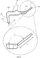
Fig. 2a is a side view of a fixing member according to a first embodiment; -
Fig. 2b is an isometric side view of a fixing member according to a first embodiment; -
Fig. 3 is a top view of a fixing member according to a first embodiment; -
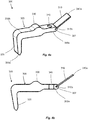
Fig. 4a is an isometric side view of a fixing member according to a second embodiment; -
Fig. 4b is an isometric side view of a fixing member according to a second embodiment; -
Fig. 5a is an isometric side view of a fixing member according to a third embodiment; -
Fig. 5b is an isometric side view of a fixing member according to a third embodiment; -
Fig. 6a is an isometric side view of a part of a frame structure and a fixing member according toFigs. 2-3 being arranged in a mounting position according to an embodiment; -
Fig. 6b is an isometric side view of a part of a frame structure and a fixing member according toFigs. 2-3 being arranged in a mounting position according to an embodiment; -
Fig. 7 is an isometric side view of a fixing member according toFigs. 2-3 being arranged in a mounting position according to an embodiment; -
Fig. 8 is an isometric side view of a fixing member according toFigs. 2-3 being arranged in a restrained position according to an embodiment; -
Fig. 9 is an isometric side view of a fixing member according toFig. 5a-b being arranged in a mounting position according to an embodiment; and -
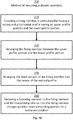
Fig. 10 is a block scheme illustrating a method of mounting a shower assembly using a fixing member according to an embodiment. -
Fig. 1 illustrates a shower enclosure orshower cubicle 10. The shower cubicle orshower enclosure 10 comprises aframe structure 20 and a plurality of shower panels. Theframe structure 20 may comprises acolumn 22,horizontal profiles 40 andvertical profiles 30. - In the embodiment shown in
Fig. 1 , theframe structure 20 comprises a plurality ofvertical profiles 30 and a plurality ofhorizontal profiles 40 creating a frame like structure. The number of horizontal andvertical profiles - The
column 22 may also be seen as a vertical profile. Thecolumn 22 extends in a vertical direction to define the vertical extension of the shower cubicle. Preferably, thecolumn 22 is provided with suitable connections for supplying water. Thecolumn 22 may for example be provided with a water mixing tap whereby the user is allowed to open and close the supply of water, as well as adjusting the desired temperature of the discharged water by applying the correct mix of hot and cold water. - The plurality of shower panels are extending vertically along the length of the
vertical profiles 30 to form an enclosure. In the embodiment shown inFig. 1 , theshower cubicle 10 comprises four shower panels. However, it should be understood that the number of shower panels depends on the cross-sectional shape of the shower cubical. The shower panels may be fixed panels or doors. The shower panels is preferably being made of a thin body such as glass, plastic, or similar. - At least one of the shower panels may be provided as shower door panels. These are movably supported by the
frame structure 20 such that at least one of the shower door panels may be opened and closed. Preferably, the opening and closing may be performed by a sliding movement where the shower door panel(s) are guided in a groove (not shown) in theframe structure 20. The shower door panels may be arranged on guide units (not shown) that are guided in the groove to allow opening and closing of the shower door panels. Once closed, the shower panels should seal against the shower tray or bathroom floor such that water is prevented from escaping out from the showeringarea 10. - In an alternative embodiment, the opening and closing may be performed by a pivoting action of the particular shower panels.
- The
horizontal profiles 40 and thevertical profiles 30 are fixated to each other by a fixation arrangement. The fixation arrangement described herein can also be used to fixate a horizontal profile with thecolumn 22. The fixation arrangement comprises a fixingmember 100 that is arranged in ahorizontal profile 40 and that engages in avertical profile 40. Some of the benefits of thisnovel fixing member 100; 300; 400 is that the installation process is simplified and that the manufacturing process is cheaper. The first time the shower cubicle or shower enclosure is assembled, the fixingmember 100; 300; 400 described herein will always be arranged in a position that makes it easier for the installer to fit the fixing member into the profile. A first embodiment of the fixingmember 100; 300; 400 will now be described in detail with reference toFigs. 2-3 ,a second embodiment with reference toFigs. 4a-b and a third embodiment with reference toFigs. 5a-b , before turning to the whole fixing arrangement with reference toFig. 6 - 9 . The embodiments herein all comprise a resilient member made of a resilient material that keeps a part of the fixing member at a distance from the horizontal profile during assembly. - As seen in
Figs. 2a-b , the fixing member or fixingclaw 100 comprises anelongated body 105 having afirst end portion 105a and asecond end portion 105b. Between thefirst end portion 105a and thesecond end portion 105b anelevated portion 130 is provided. Theelevated portion 130 is preferably arranged as a raised structure in the form of a semicircle. - In this embodiment, the
wing portion 110 and themain body 105 are constructed as one piece. Hence, the whole fixingmember 100 is constructed as one unit. The fixingmember 100 is preferably constructed by a metal, and more preferably constructed in aluminium. However, the fixingmember 100 could also be constructed in plastic or a composite material. In some embodiments, the fixing member could also be constructed in other materials that allows for some deformation. Preferably, the surfaces of the fixingmember 100 are substantially flat, i.e. there are no grooves or small protrusions arranged on its surface. - In this first embodiment, a
wing portion 110 is arranged in thefirst end portion 105a of the main body. Thewing portion 110 comprises atop end 110a that is arranged at the end of thewing portion 110 that faces away from themain body 105. Before assembly of the fixingmember 100 in theframe structure 20, thewing portion 110 is arranged with a mounting angle A1 from themain body 105. In a preferred embodiment, the mounting angle A1 is between 130 and 160 degrees. More preferably, the mounting angle A1 is between 140 to 150 degrees. - The
wing portion 110 has a length of L1. The length L1 may range from 12 to 25 mm, and more preferably around 18 mm. The main thickness of thewing portion 110 is T1 and preferably ranges between 1 and 3 mm. More preferably, the main thickness of the wing portion is around 2 mm. The thickness of thewing portion 110 may be tapered, so that the thickness is bigger in the portion facing away from themain body 105 of the fixingmember 100. The tapered thickness is illustrated inFig. 2a , where the thickness T2 of thewing portion 110 is smaller than the thickness T1 near the second end of themain body 105. The smaller thickness T2 may for example be around 1,5 mm. - At the
second end portion 105b of themain body 105 of the fixingmember 100, ahook portion 120 is arranged. Thehook portion 120 is extending in a direction mainly opposite thewing portion 110. Thehook portion 120 comprises afirst end 120a. When the fixingmember 100 is assembled in the frame structure, thefirst end 120a of thehook portion 120 mainly faces downwards in the direction of thevertical profile 30. Thefirst end 120a of thehook portion 120 is arranged with atapered surface 122. Thetapered surface 122 has an inclination of an angle A3. The angle A3 may range between 20 and 40 degrees, and more preferably the angle A3 is around 30 degrees. -
Fig. 3 illustrates the fixingmember 100 as seen from above. As seen inFig. 3 , the length of themain body 105 and thewing portion 110 is denoted L2. The length L2 of themain body 105 and thewing portion 110 is preferably around 50 to 70 mm, and more preferably around 59-62 mm long. The width of themain body 105, and the width of thewing portion 110, is denoted W1. The width W1 is preferably around 5 to 10 mm, and more preferably around 8 mm wide. - An
opening 140, such as for example a through hole, is arranged on themain body 105 of the fixingclaw 100. In this embodiment, the throughhole 140 is arranged closer to thefirst end 105a of the main body than thesecond end 105b. As will be explained more with reference toFigs. 6-8 , the throughhole 140 is adapted to receive a fastening member 50 (as seen inFigs. 6a-b ) such as a screw or similar. Thefastening member 50 will be used to fixate the fixingmember 100 to theframe structure 20. - If the fixing
member 100 inFig. 3 is seen from left to right, thehook portion 120 is arranged to the left end of the structure. Theelevated portion 130 is arranged between thehook portion 120 and the throughhole 140. The throughhole 140 is in turn arranged between theelevated portion 130 and thewing portion 110. Thewing portion 110 is thus arranged to the right end of the structure. - A second embodiment of the fixing
member 100 is shown inFigs. 4a- 4b . The difference compared to the first embodiment according toFigs. 2-3 relates to thewing portion 310. - The fixing
member 300 comprises anelongated body 305 having afirst end portion 305a and asecond end portion 305b. Between thefirst end portion 305a and thesecond end portion 305b anelevated portion 330 is provided. Theelevated portion 330 is preferably arranged as a raised structure in the form of a semicircle. At thesecond end portion 305b of themain body 305 of the fixingmember 300, ahook portion 320 is arranged. Additionally, anopening 340, such as for example a through hole, is arranged on themain body 305 of the fixingmember 300. - The
first end portion 305a of the main body comprises a receivingsection 307 configured to receive awing portion 310. Thewing portion 310 comprises atop end 310a and abottom end 310b. Thebottom end 310b of thewing portion 310 is arranged to be received in the receivingsection 307 of themain body 305. Thetop end 310a is arranged at the end of thewing portion 310 that faces away from themain body 305. - The
wing portion 310 and themain body 305 are thus constructed as two separate elements. Thewing portion 310 and themain body 305 may be constructed in the same material, or in different materials. Thewing portion 310 may for example be constructed in spring steel, aluminium or any other deformable material. Themain body 305 could for example be constructed in aluminium, plastic or a composite material. In some embodiments, - Before assembly of the fixing
member 300 in theframe structure 20, thewing portion 310 is arranged with a mounting angle A1 from themain body 305 as described with reference to the first embodiment seen inFigs. 2-3 . - The benefits of this embodiment is that the fixing
member 300 will not deform permanently during mounting of the shower enclosure or cubicle, since it is easy to remove thedeformed wing portion 310 and arrange a new one inside the receiving section of the main body. - A third embodiment of the fixing
member 400 is shown inFigs. 5a- 5b . The difference compared to the previous embodiment relates to the resilient member. - The fixing
member 400 comprises anelongated body 405 having afirst end portion 405a and asecond end portion 405b. Between thefirst end portion 405a and thesecond end portion 405b anelevated portion 430 is provided. Theelevated portion 430 is preferably arranged as a raised structure in the form of a semicircle. At thesecond end portion 405b of themain body 405 of the fixingmember 400, ahook portion 420 is arranged. Additionally, anopening 440, such as for example a through hole, is arranged on themain body 405 of the fixingmember 400. - A
resilient member 52 is arranged on top of themain portion 405 of the fixingmember 400. In a preferred embodiment, theresilient member 52 is arranged above the throughhole 440 on themain body 405, so that it will be compressed when thefastening member 50 is arranged above it and subsequently fastened and/or tightened. Theresilient member 52 may be a blade spring, spiral spring or a compression spring. - During assembly the
resilient member 52 keeps thehook portion 420 at a distance from the horizontal profile. Theresilient member 52 is kept in place by afastening member 50. Thefastening member 50 is preferably a screw, bolt, or similar structure. Thefastening member 50 is to be arranged in thehole 440 of the fixingmember 400. The cooperation between theresilient member 52 and thefastening member 50 will be described more in detail with reference toFig. 9 . - The benefits of this embodiment is that the fixing
member 400 will not deform permanently during mounting of the shower enclosure or cubicle. If needed, theresilient member 52 can easily be replaced by a new member. -
Figs. 6-8 illustrates different stages of the process of assembling avertical profile 30 with ahorizontal profile 40 using a fixingmember resilient member 52 is a wing portion (as the embodiments shown inFigs. 2-3 andFigs. 4a-b ). However, as will be apparent fromFig. 9 , the same concept applies for the fixingmember 400 having another type ofresilient member 52. -
Figs. 6a-b shows the stage just before thehorizontal profile 40 is connected with thevertical profile 30.Figs. 6a and 6b illustrates the same assembly stage, where the outer parts of theprofiles Fig. 6b to facilitate understanding. - The
vertical profile 30 comprises atop portion 32. Thetop portion 32 comprises at least onerecess 36. Therecess 36 is preferably a vertically extendingrecess 36. The shape of therecess 36 is such that it is configured to receive thehook portion 120 of the fixingmember 100; 300. Thetop portion 32 of thevertical profile 30 may also comprise a grippingstructure 34. The grippingstructure 34 may be arranged to receive a shower panel. - The
horizontal profile 40 comprises anupper profile portion 44 and alower profile portion 46. Theupper profile portion 44 and alower profile portion 46 both extends along the length of theprofile 40. Theupper profile portion 44 is arranged in a position above thelower profile portion 46. - The
upper profile portion 44 comprises anupper surface 44a and alower surface 44b. Theupper surface 44a is arranged such that it is positioned above thelower surface 44b. Theupper profile portion 44 of thehorizontal profile 40 further comprises at least one throughhole 42. The hole is preferably arranged at a distance D1 from an end of thehorizontal profile 40. The distance D1 depends on the dimensions of the fixingmember 100; 300, but may for example range between 20 and 60 mm. Although not shown, thehorizontal profile 40 may be arranged with two through holes, each arranged at a distance D1 from each of the ends of theprofile 40. In this way, thehorizontal profile 40 may be connected to twovertical profiles 30. - The fixing
member 100; 300 is fixated in thehorizontal profile 40 by afastening member 50. Thefastening member 50 is preferably a screw, bolt, or similar structure. Thefastening member 50 is to be arranged in the at least one throughhole 42 of theupper profile portion 44 and through thehole 140; 340 of the fixingclaw 100; 300 where it is fixated. - When the fixing
member 100; 300 is arranged in thehorizontal profile 40, themain body 105; 305 of the fixingmember 100; 300 is arranged in between theupper profile portion 44 and thelower profile portion 46. Theelevated portion 130; 330 is in close conjunction with thelower surface 44b of theupper profile portion 44. When the resilient member is a wing portion, thetop end 110a; 310a of thewing portion 110; 330 is arranged in a position in close conjunction with thelower surface 44b of theupper profile portion 44. - In
Figs. 6a-b , the fixingmember 100; 300 is in an open position, also referred to as the mounting position, and the fixingmember 100; 300 has not yet been arranged in the vertical profile 30 (hence thefastening member 50 has not yet been tightened). The fixingmember 100; 300 is in an open position in the sense that thehook portion 120; 320 is prevented from falling down towards the vertical profile and/or from falling inwards towards the center of thehorizontal frame 40 or thelower profile portion 46. This mounting position is maintained by theresilient member 110; 310, as soon will be described more in detail. - The mounting position facilitates the entry of the
hook portion 120; 320 of the fixingmember 100; 300 into the vertical profile. The assembly of the of thehorizontal profile 40 onto thevertical profile hook portion 120; 320 is clearly visible for the person installing the shower cubicle or shower enclosure, so that he/she easily can fit thehook portion 120; 320 into therecess 36 of thevertical profile 30. - When the fixing
claw wing portion 110; 310 is arranged with a mounting angle A1 from themain body 105; 305. Once the vertical profile is assembled with the horizontal profile and thefastening member 50 is fastened or tightened, this angle, referred to as a restraining angle A2, will be changed due to the pressure generated once the fasteningmember 50 is fastened causing thewing portion 100; 300 to deform. When in the mounting position, thewing portion 110; 310 is arranged to keeping thehook portion 120; 320 at a distance D2 from the horizontal profile. The mounting position is thus used during assembly of the frame structure. - In
Fig. 7 , thehorizontal profile 40 and thevertical profile 30 are assembled. Thehook portion 120; 320 of the fixingclaw recess 36 of thevertical profile 30. In the position as shown inFig. 7 , thefastening member 50 has not yet been fastened or tightened. Hence, thewing portion 110; 310 is still arranged with an angle A1 from themain body 105, i.e. the fixingmember 100; 300 is in the mounting position. -
Fig. 8 illustrates the situation where thefastening member 50 has been fastened and/or tightened. The resilient member will be compressed by the applied pressure on thefastening member 50, so that thevertical profile 30 and thehorizontal profile 40 are securely arranged to each other. During fastening of thefastening member 50, thehook portion 120; 320; 420 will clamp thevertical profile 30 towards thehorizontal profile 40. Thefirst end 120a; 320a; 420a of thehook portion 120; 320; 420 is forced downwards and/or inwards towards thelower profile portion 46 of thehorizontal profile 40. In this way the distance between thehook portion 120; 320; 420 and thehorizontal profile 40 is reduced from the original distance D2. - In the embodiment where the resilient member is a wing portion, the
wing portion 110; 310 will be flattened by the pressure so that the angle between thewing portion 110; 310 and themain body 105; 305 of the fixingmember 100; 300 is increased to a restraining angle A2. The restraining angle A2 is slightly increased compared to the original angle A1. Preferably, the restraining angle A2 is increased by 1 to 15 degrees compared to the original angle A1. In some embodiments thewing portion 110; 310 will flatten so much by the applied pressure that it breaks, which also has to be seen as an increased angle. - The
vertical profile 30 and thehorizontal profile 40 may be disassembled from each other by loosening or removing thefastening member 50. The fixingmember 100; 300; 400 may be reused. - If the fixing member is constructed in one piece, as in the first embodiment relating to
Figs. 2-3 , thewing portion 110 is permanently deformed and thehook portion 120 will not be in an open position in its next assembly. Hence, when reused the fixingmember hook portion 120 into therecess 36 of thevertical profile 30. - If the fixing
member 300 is constructed in two pieces, as in the second embodiment relating toFigs. 4a-b , thewing portion 310 could be changed to anew wing portion 310 that has not been deformed, the fixingmember 300 can be reused with the same benefits as a new fixing member. -
Fig. 9 illustrates assembling of avertical profile 30 with ahorizontal profile 40 using the fixingmember 400 according to the third embodiment shown inFigs. 5a-b . As previously been described, the resilient member is compressed by the applied pressure on thefastening member 50 so that thevertical profile 30 and thehorizontal profile 40 are securely arranged to each other. During fastening of thefastening member 50, thehook portion 420 will clamp thevertical profile 30 towards thehorizontal profile 40. Thefirst end 420a of thehook portion 420 is forced downwards and/or inwards towards thelower profile portion 46 of thehorizontal profile 40. In this way the distance between thehook portion 420 and thehorizontal profile 40 is reduced from the original distance D2. - The
vertical profile 30 and thehorizontal profile 40 may be disassembled from each other by loosening or removing thefastening member 50. Theresilient member 52 made from a resilient material, such as a blade spring, allows the fixing member (300) to be reused with the same benefits over and over again. - A method of mounting a shower assembly will now be described with reference to
Fig. 10 . In afirst step 210, avertical profile 30, ahorizontal profile 40 and a fixingmember 100; 300; 400 is provided. The fixingmember 100; 300; 400 is arranged in a mounting position. In the embodiments where the resilient member is a wing portion, thewing portion 110; 310 is arranged with a mounting angle A1 from themain body 105; 305. - If the fixing
member 300 is arranged as two separate pieces, with themain body 305 and thehook portion 320 as one piece and the resilient member being awing portion 310 as another piece, an additional step is required where thewing portion 310 is arranged in the receivingsection 307 of themain body 305 which is configured to receive thewing portion 310. - In a
next step 220, the fixingmember 100; 300; 400 is arranged in thehorizontal profile 40. The fixingmember 100; 300; 400 is arranged in between theupper profile portion 44 and thelower profile portion 46 so that theelevated portion 130; 330; 440 is in close conjunction with thelower surface 44b of theupper profile portion 44. In the embodiments where the resilient member is a wing portion, thetop end 110a; 310a of thewing portion 110; 310 is arranged in a position in close conjunction with thelower surface 44b of theupper profile portion 44. - The
resilient member 110; 310; 52 is arranged to keep thehook portion 120; 320; 420 at a distance D2 from the horizontal profile during the mounting process. Thefastening member 50 is arranged, but not fastened, in order to keep the fixingmember 100; 300; 400 in place. - In yet a further step, the installer places 230 the
hook portion 120; 320; 420, being arranged in thehorizontal profile 40, into therecess 36 of thevertical profile 30. Since theresilient member 110; 310; 52 keeps thehook portion 120; 320; 420 at a distance D2 from the horizontal profile, it is easy for the installer to guide thehook portion 120; 320; 420 into therecess 36. - In a
next step 240, thefastening member 50 is fastened and tightened, so that thehook portion 120; 320; 420 will clamp thevertical profile 30 towards thehorizontal profile 40. The resilient member will deform so that thehorizontal profile 40 and thevertical profile 30 are securely arranged to each other. - In the embodiments where the resilient member is a wing portion, the
wing portion 110; 310 will be flattened by the pressure, so that the angle between thewing portion 110; 310 and themain body 105; 305 of the fixingmember 100; 300 is increased to a restraining angle A2 that is larger than the mounting angle A1. - Although the present invention has been described above with reference to specific embodiments, it is not intended to be limited to the specific form set forth herein. Rather, the invention is limited only by the accompanying claims and, other embodiments than the specific above are equally possible within the scope of these appended claims.
Claims (16)
- A fixing member (100; 300; 400) for fixating a horizontal profile (40) with a vertical profile (30) in a shower assembly, wherein the fixing member (100; 300; 400) comprises:a main body (105; 305; 405) having a first end portion (105a; 305a; 405a) and a second end portion (105b; 305b; 405b), comprising an opening (140; 340; 440) arranged to receive a fastening member (50) in order to fixate the fixing member (100; 300; 400) to the horizontal profile (40);a hook portion (120; 320; 420) being arranged at the second end portion (105b; 305b; 405b) to engage with a recess (36) in the vertical profile (30); andat least one resilient member (110; 310; 52) for keeping the hook portion (120; 320; 420) at a distance (D2) from the horizontal profile (40) during assembly.
- The fixing member (400) according to claim 1, wherein the at least one flexible means (52) is a spring (52).
- The fixing member (100; 300) according to claim 1, wherein the at least one flexible means is a wing portion (110; 310) being arranged at the first end portion (105a; 305a) for keeping the hook portion (120; 320) at a distance (D2) from the horizontal profile (40) during assembly.
- The fixing member (100; 300) according to claim 3, wherein the fixing member (100; 300) is configured to be arranged in a mounting position and in a restrained position, wherein in the mounting position the wing portion (110; 310) is arranged with a mounting angle (A1) from the main body (105; 305) and in the restrained position the wing portion (110; 310) is arranged with a restraining angle (A2) from the main body (105; 305), wherein the restraining angle (A2) is greater than the mounting angle (A1).
- The fixing member (100; 300) according to claim 4, wherein the fixing member (100; 300) is arranged in a mounting position during the assembly of the horizontal profile (40) and the vertical profile (30).
- The fixing member (100; 300) according to claim 4 or 5, wherein the fixing member (100; 300) is arranged in a restrained position once the horizontal profile (40) and the vertical profile (30) are fixated to each other.
- The fixing member (100; 300) according to any one of claims 3 to 6, wherein the position of the fixing member (100; 300) is changed from the mounting position to the restrained position once the fastening member (50) is fastened and/or tightened in the opening (140; 340) of the fixing member (100; 300).
- The fixing member (100; 300) according to any one claims 3 to 7, wherein the hook portion (120; 320) and the wing portion (110; 310) mainly extends in an opposite direction from each other.
- The fixing member (100) according to any one of claims 3 to 8, wherein the main body (105), the hook portion (120) and the at least one wing portion (110) are constructed as one piece.
- The fixing member (300) according to any one of claims 3-8, wherein the main body (305) and the at least one wing portion (310) are constructed as separate elements, and wherein the first end portion (305a) of the main body comprises a receiving section (307) configured to receive the wing portion (310).
- A shower assembly comprising at least one fixing member (100; 300) according to any one of the claims 1-10, at least one a horizontal profile (40) and at least one vertical profile (30).
- The shower assembly according to claim 11, wherein the horizontal profile (40) comprises an upper profile portion (44) and a lower profile portion (46), and the vertical profile (30) comprises a vertically extending recess (36), and wherein the fixing member (100; 300) is arranged between the upper profile portion (44) and the lower profile portion (46).
- The shower assembly according to claim 12, wherein the upper profile portion (44) of the horizontal profile (40) comprises at least one opening (42) configured to receive a fastening member (50) in order to fixate the fixing member (100; 300) to the horizontal profile (40).
- The shower assembly according to claim 12 or 13, wherein the upper profile portion (44) of the horizontal profile (40) further comprises an upper surface (44a) and a lower surface (44b), wherein a top end (110a; 310a) of the wing portion (110; 310) is arranged in a position in close conjunction with the lower surface (44b) of the upper profile portion (44).
- A method of mounting a shower assembly, comprising the steps of:providing (210) a fixing member according to any one of claims 1 to 10, a vertical profile having a recess and a horizontal profile having an upper profile portion and a lower profile portion;arranging (220) the fixing member between the upper profile portion and the lower profile portion;arranging (230) the hook portion of the fixing member into the recess of the vertical profile;fastening (240) a fastening member to the fixing member and the horizontal profile so that the fixing member changes position from a mounting position to a restrained position.
- The method according to claim 15, wherein the flexible means is at least one wing portion (110; 310) being arranged at the first end portion (105a; 305a), and wherein in the mounting position the wing portion (110; 310) is arranged with a mounting angle (A1) from the main body (105; 305) and in the restrained position the wing portion (110; 310) is arranged with a restraining angle (A2) from the main body (105; 305), wherein the restraining angle (A2) is greater than the mounting angle (A1).
Priority Applications (3)
| Application Number | Priority Date | Filing Date | Title |
|---|---|---|---|
| EP17211176.7A EP3505030B1 (en) | 2017-12-29 | 2017-12-29 | Fixing member for shower profiles |
| LTEP17211176.7T LT3505030T (en) | 2017-12-29 | 2017-12-29 | Fixing member for shower profiles |
| DK17211176.7T DK3505030T3 (en) | 2017-12-29 | 2017-12-29 | FUSER ELEMENT FOR SHOWER CABIN PROFILES |
Applications Claiming Priority (1)
| Application Number | Priority Date | Filing Date | Title |
|---|---|---|---|
| EP17211176.7A EP3505030B1 (en) | 2017-12-29 | 2017-12-29 | Fixing member for shower profiles |
Publications (2)
| Publication Number | Publication Date |
|---|---|
| EP3505030A1 true EP3505030A1 (en) | 2019-07-03 |
| EP3505030B1 EP3505030B1 (en) | 2022-04-27 |
Family
ID=60856977
Family Applications (1)
| Application Number | Title | Priority Date | Filing Date |
|---|---|---|---|
| EP17211176.7A Not-in-force EP3505030B1 (en) | 2017-12-29 | 2017-12-29 | Fixing member for shower profiles |
Country Status (3)
| Country | Link |
|---|---|
| EP (1) | EP3505030B1 (en) |
| DK (1) | DK3505030T3 (en) |
| LT (1) | LT3505030T (en) |
Citations (3)
| Publication number | Priority date | Publication date | Assignee | Title |
|---|---|---|---|---|
| US3182771A (en) * | 1963-12-16 | 1965-05-11 | Loup Engineering Corp | Corner joinder of channelled frames |
| FR2267472A1 (en) * | 1974-04-09 | 1975-11-07 | Syma Intercontinental Sa | Assembly device of profiled sections and panels - uses T-bolt with conical recess locked with pointed grub screw |
| US5624201A (en) * | 1992-06-09 | 1997-04-29 | Offenbroich; Adrian | Clamping device |
-
2017
- 2017-12-29 LT LTEP17211176.7T patent/LT3505030T/en unknown
- 2017-12-29 DK DK17211176.7T patent/DK3505030T3/en active
- 2017-12-29 EP EP17211176.7A patent/EP3505030B1/en not_active Not-in-force
Patent Citations (3)
| Publication number | Priority date | Publication date | Assignee | Title |
|---|---|---|---|---|
| US3182771A (en) * | 1963-12-16 | 1965-05-11 | Loup Engineering Corp | Corner joinder of channelled frames |
| FR2267472A1 (en) * | 1974-04-09 | 1975-11-07 | Syma Intercontinental Sa | Assembly device of profiled sections and panels - uses T-bolt with conical recess locked with pointed grub screw |
| US5624201A (en) * | 1992-06-09 | 1997-04-29 | Offenbroich; Adrian | Clamping device |
Also Published As
| Publication number | Publication date |
|---|---|
| DK3505030T3 (en) | 2022-06-20 |
| EP3505030B1 (en) | 2022-04-27 |
| LT3505030T (en) | 2022-05-25 |
Similar Documents
| Publication | Publication Date | Title |
|---|---|---|
| CA2812566C (en) | Shower door assembly | |
| US20110219722A1 (en) | Fixture for securing a balustrade | |
| MXPA04011435A (en) | SUPPORT SYSTEM FOR SOLAR PANELS. | |
| CN106414880A (en) | Adjustment device for shower door and shower door | |
| US20130333160A1 (en) | Adjustable hinge | |
| EP3505030B1 (en) | Fixing member for shower profiles | |
| CN1650084A (en) | Components including door leaves and hinges and shower enclosures | |
| AU2014200412A1 (en) | Door Assembly | |
| DE102005044459A1 (en) | Fastening device for fastening an element facade to a building | |
| CA2859680C (en) | Shower door hinge | |
| US20070158957A1 (en) | Double door security device | |
| US7804032B2 (en) | Section for a window or facade and electric cable for a section for a window, door or facade | |
| HU222158B1 (en) | Rúdcsomópont | |
| WO2022035999A1 (en) | Accessory structure mounting system | |
| AT516256A4 (en) | ARMING PROFILE FOR A DOOR ELEMENT IN A PARTITIONING SYSTEM | |
| EP1891282A1 (en) | Support structure and profile rail therefore | |
| US5107647A (en) | Beam and connector block assembly | |
| US3328057A (en) | Rail system | |
| EP2918764B1 (en) | Securing device for securing a glass panel to a profile | |
| KR100762784B1 (en) | Door frame fixture | |
| KR100725115B1 (en) | Bidirectional support of glass panel | |
| KR102917380B1 (en) | Detachable and foldable blocking water module | |
| EP3505029A1 (en) | A shower profile | |
| KR200237257Y1 (en) | All glass shower booth | |
| EP4368791A1 (en) | Improved clamp for the composition of a technical structure for furniture, protection and/or delimitation |
Legal Events
| Date | Code | Title | Description |
|---|---|---|---|
| PUAI | Public reference made under article 153(3) epc to a published international application that has entered the european phase |
Free format text: ORIGINAL CODE: 0009012 |
|
| STAA | Information on the status of an ep patent application or granted ep patent |
Free format text: STATUS: THE APPLICATION HAS BEEN PUBLISHED |
|
| AK | Designated contracting states |
Kind code of ref document: A1 Designated state(s): AL AT BE BG CH CY CZ DE DK EE ES FI FR GB GR HR HU IE IS IT LI LT LU LV MC MK MT NL NO PL PT RO RS SE SI SK SM TR |
|
| AX | Request for extension of the european patent |
Extension state: BA ME |
|
| STAA | Information on the status of an ep patent application or granted ep patent |
Free format text: STATUS: REQUEST FOR EXAMINATION WAS MADE |
|
| 17P | Request for examination filed |
Effective date: 20200102 |
|
| RBV | Designated contracting states (corrected) |
Designated state(s): AL AT BE BG CH CY CZ DE DK EE ES FI FR GB GR HR HU IE IS IT LI LT LU LV MC MK MT NL NO PL PT RO RS SE SI SK SM TR |
|
| STAA | Information on the status of an ep patent application or granted ep patent |
Free format text: STATUS: EXAMINATION IS IN PROGRESS |
|
| 17Q | First examination report despatched |
Effective date: 20200617 |
|
| GRAP | Despatch of communication of intention to grant a patent |
Free format text: ORIGINAL CODE: EPIDOSNIGR1 |
|
| STAA | Information on the status of an ep patent application or granted ep patent |
Free format text: STATUS: GRANT OF PATENT IS INTENDED |
|
| INTG | Intention to grant announced |
Effective date: 20211130 |
|
| RIN1 | Information on inventor provided before grant (corrected) |
Inventor name: MATTSSON, MARTIN |
|
| GRAS | Grant fee paid |
Free format text: ORIGINAL CODE: EPIDOSNIGR3 |
|
| GRAA | (expected) grant |
Free format text: ORIGINAL CODE: 0009210 |
|
| STAA | Information on the status of an ep patent application or granted ep patent |
Free format text: STATUS: THE PATENT HAS BEEN GRANTED |
|
| AK | Designated contracting states |
Kind code of ref document: B1 Designated state(s): AL AT BE BG CH CY CZ DE DK EE ES FI FR GB GR HR HU IE IS IT LI LT LU LV MC MK MT NL NO PL PT RO RS SE SI SK SM TR |
|
| REG | Reference to a national code |
Ref country code: GB Ref legal event code: FG4D |
|
| REG | Reference to a national code |
Ref country code: CH Ref legal event code: EP |
|
| REG | Reference to a national code |
Ref country code: DE Ref legal event code: R096 Ref document number: 602017056496 Country of ref document: DE |
|
| REG | Reference to a national code |
Ref country code: AT Ref legal event code: REF Ref document number: 1486268 Country of ref document: AT Kind code of ref document: T Effective date: 20220515 |
|
| REG | Reference to a national code |
Ref country code: FI Ref legal event code: FGE |
|
| REG | Reference to a national code |
Ref country code: IE Ref legal event code: FG4D |
|
| REG | Reference to a national code |
Ref country code: DK Ref legal event code: T3 Effective date: 20220614 |
|
| REG | Reference to a national code |
Ref country code: NO Ref legal event code: T2 Effective date: 20220427 |
|
| REG | Reference to a national code |
Ref country code: SE Ref legal event code: TRGR |
|
| REG | Reference to a national code |
Ref country code: EE Ref legal event code: FG4A Ref document number: E022377 Country of ref document: EE Effective date: 20220620 |
|
| REG | Reference to a national code |
Ref country code: NL Ref legal event code: MP Effective date: 20220427 |
|
| REG | Reference to a national code |
Ref country code: AT Ref legal event code: MK05 Ref document number: 1486268 Country of ref document: AT Kind code of ref document: T Effective date: 20220427 |
|
| PG25 | Lapsed in a contracting state [announced via postgrant information from national office to epo] |
Ref country code: NL Free format text: LAPSE BECAUSE OF FAILURE TO SUBMIT A TRANSLATION OF THE DESCRIPTION OR TO PAY THE FEE WITHIN THE PRESCRIBED TIME-LIMIT Effective date: 20220427 |
|
| PG25 | Lapsed in a contracting state [announced via postgrant information from national office to epo] |
Ref country code: PT Free format text: LAPSE BECAUSE OF FAILURE TO SUBMIT A TRANSLATION OF THE DESCRIPTION OR TO PAY THE FEE WITHIN THE PRESCRIBED TIME-LIMIT Effective date: 20220829 Ref country code: HR Free format text: LAPSE BECAUSE OF FAILURE TO SUBMIT A TRANSLATION OF THE DESCRIPTION OR TO PAY THE FEE WITHIN THE PRESCRIBED TIME-LIMIT Effective date: 20220427 Ref country code: GR Free format text: LAPSE BECAUSE OF FAILURE TO SUBMIT A TRANSLATION OF THE DESCRIPTION OR TO PAY THE FEE WITHIN THE PRESCRIBED TIME-LIMIT Effective date: 20220728 Ref country code: ES Free format text: LAPSE BECAUSE OF FAILURE TO SUBMIT A TRANSLATION OF THE DESCRIPTION OR TO PAY THE FEE WITHIN THE PRESCRIBED TIME-LIMIT Effective date: 20220427 Ref country code: BG Free format text: LAPSE BECAUSE OF FAILURE TO SUBMIT A TRANSLATION OF THE DESCRIPTION OR TO PAY THE FEE WITHIN THE PRESCRIBED TIME-LIMIT Effective date: 20220727 Ref country code: AT Free format text: LAPSE BECAUSE OF FAILURE TO SUBMIT A TRANSLATION OF THE DESCRIPTION OR TO PAY THE FEE WITHIN THE PRESCRIBED TIME-LIMIT Effective date: 20220427 |
|
| PG25 | Lapsed in a contracting state [announced via postgrant information from national office to epo] |
Ref country code: RS Free format text: LAPSE BECAUSE OF FAILURE TO SUBMIT A TRANSLATION OF THE DESCRIPTION OR TO PAY THE FEE WITHIN THE PRESCRIBED TIME-LIMIT Effective date: 20220427 Ref country code: PL Free format text: LAPSE BECAUSE OF FAILURE TO SUBMIT A TRANSLATION OF THE DESCRIPTION OR TO PAY THE FEE WITHIN THE PRESCRIBED TIME-LIMIT Effective date: 20220427 Ref country code: IS Free format text: LAPSE BECAUSE OF FAILURE TO SUBMIT A TRANSLATION OF THE DESCRIPTION OR TO PAY THE FEE WITHIN THE PRESCRIBED TIME-LIMIT Effective date: 20220827 |
|
| REG | Reference to a national code |
Ref country code: DE Ref legal event code: R097 Ref document number: 602017056496 Country of ref document: DE |
|
| PG25 | Lapsed in a contracting state [announced via postgrant information from national office to epo] |
Ref country code: SM Free format text: LAPSE BECAUSE OF FAILURE TO SUBMIT A TRANSLATION OF THE DESCRIPTION OR TO PAY THE FEE WITHIN THE PRESCRIBED TIME-LIMIT Effective date: 20220427 Ref country code: SK Free format text: LAPSE BECAUSE OF FAILURE TO SUBMIT A TRANSLATION OF THE DESCRIPTION OR TO PAY THE FEE WITHIN THE PRESCRIBED TIME-LIMIT Effective date: 20220427 Ref country code: RO Free format text: LAPSE BECAUSE OF FAILURE TO SUBMIT A TRANSLATION OF THE DESCRIPTION OR TO PAY THE FEE WITHIN THE PRESCRIBED TIME-LIMIT Effective date: 20220427 Ref country code: CZ Free format text: LAPSE BECAUSE OF FAILURE TO SUBMIT A TRANSLATION OF THE DESCRIPTION OR TO PAY THE FEE WITHIN THE PRESCRIBED TIME-LIMIT Effective date: 20220427 |
|
| PGFP | Annual fee paid to national office [announced via postgrant information from national office to epo] |
Ref country code: SE Payment date: 20221220 Year of fee payment: 6 Ref country code: NO Payment date: 20221219 Year of fee payment: 6 Ref country code: LV Payment date: 20221121 Year of fee payment: 6 Ref country code: LT Payment date: 20221123 Year of fee payment: 6 Ref country code: FI Payment date: 20221209 Year of fee payment: 6 Ref country code: EE Payment date: 20221122 Year of fee payment: 6 Ref country code: DK Payment date: 20221209 Year of fee payment: 6 |
|
| PLBE | No opposition filed within time limit |
Free format text: ORIGINAL CODE: 0009261 |
|
| STAA | Information on the status of an ep patent application or granted ep patent |
Free format text: STATUS: NO OPPOSITION FILED WITHIN TIME LIMIT |
|
| PG25 | Lapsed in a contracting state [announced via postgrant information from national office to epo] |
Ref country code: AL Free format text: LAPSE BECAUSE OF FAILURE TO SUBMIT A TRANSLATION OF THE DESCRIPTION OR TO PAY THE FEE WITHIN THE PRESCRIBED TIME-LIMIT Effective date: 20220427 |
|
| 26N | No opposition filed |
Effective date: 20230130 |
|
| PG25 | Lapsed in a contracting state [announced via postgrant information from national office to epo] |
Ref country code: SI Free format text: LAPSE BECAUSE OF FAILURE TO SUBMIT A TRANSLATION OF THE DESCRIPTION OR TO PAY THE FEE WITHIN THE PRESCRIBED TIME-LIMIT Effective date: 20220427 |
|
| REG | Reference to a national code |
Ref country code: DE Ref legal event code: R119 Ref document number: 602017056496 Country of ref document: DE |
|
| P01 | Opt-out of the competence of the unified patent court (upc) registered |
Effective date: 20230527 |
|
| REG | Reference to a national code |
Ref country code: CH Ref legal event code: PL |
|
| GBPC | Gb: european patent ceased through non-payment of renewal fee |
Effective date: 20221229 |
|
| REG | Reference to a national code |
Ref country code: BE Ref legal event code: MM Effective date: 20221231 |
|
| PG25 | Lapsed in a contracting state [announced via postgrant information from national office to epo] |
Ref country code: LU Free format text: LAPSE BECAUSE OF NON-PAYMENT OF DUE FEES Effective date: 20221229 |
|
| PG25 | Lapsed in a contracting state [announced via postgrant information from national office to epo] |
Ref country code: LI Free format text: LAPSE BECAUSE OF NON-PAYMENT OF DUE FEES Effective date: 20221231 Ref country code: IE Free format text: LAPSE BECAUSE OF NON-PAYMENT OF DUE FEES Effective date: 20221229 Ref country code: GB Free format text: LAPSE BECAUSE OF NON-PAYMENT OF DUE FEES Effective date: 20221229 Ref country code: DE Free format text: LAPSE BECAUSE OF NON-PAYMENT OF DUE FEES Effective date: 20230701 Ref country code: CH Free format text: LAPSE BECAUSE OF NON-PAYMENT OF DUE FEES Effective date: 20221231 |
|
| PG25 | Lapsed in a contracting state [announced via postgrant information from national office to epo] |
Ref country code: FR Free format text: LAPSE BECAUSE OF NON-PAYMENT OF DUE FEES Effective date: 20221231 Ref country code: BE Free format text: LAPSE BECAUSE OF NON-PAYMENT OF DUE FEES Effective date: 20221231 |
|
| PG25 | Lapsed in a contracting state [announced via postgrant information from national office to epo] |
Ref country code: IT Free format text: LAPSE BECAUSE OF FAILURE TO SUBMIT A TRANSLATION OF THE DESCRIPTION OR TO PAY THE FEE WITHIN THE PRESCRIBED TIME-LIMIT Effective date: 20220427 |
|
| PG25 | Lapsed in a contracting state [announced via postgrant information from national office to epo] |
Ref country code: HU Free format text: LAPSE BECAUSE OF FAILURE TO SUBMIT A TRANSLATION OF THE DESCRIPTION OR TO PAY THE FEE WITHIN THE PRESCRIBED TIME-LIMIT; INVALID AB INITIO Effective date: 20171229 |
|
| PG25 | Lapsed in a contracting state [announced via postgrant information from national office to epo] |
Ref country code: CY Free format text: LAPSE BECAUSE OF FAILURE TO SUBMIT A TRANSLATION OF THE DESCRIPTION OR TO PAY THE FEE WITHIN THE PRESCRIBED TIME-LIMIT Effective date: 20220427 |
|
| PG25 | Lapsed in a contracting state [announced via postgrant information from national office to epo] |
Ref country code: MK Free format text: LAPSE BECAUSE OF FAILURE TO SUBMIT A TRANSLATION OF THE DESCRIPTION OR TO PAY THE FEE WITHIN THE PRESCRIBED TIME-LIMIT Effective date: 20220427 |
|
| PG25 | Lapsed in a contracting state [announced via postgrant information from national office to epo] |
Ref country code: MC Free format text: LAPSE BECAUSE OF FAILURE TO SUBMIT A TRANSLATION OF THE DESCRIPTION OR TO PAY THE FEE WITHIN THE PRESCRIBED TIME-LIMIT Effective date: 20220427 |
|
| PG25 | Lapsed in a contracting state [announced via postgrant information from national office to epo] |
Ref country code: MC Free format text: LAPSE BECAUSE OF FAILURE TO SUBMIT A TRANSLATION OF THE DESCRIPTION OR TO PAY THE FEE WITHIN THE PRESCRIBED TIME-LIMIT Effective date: 20220427 |
|
| REG | Reference to a national code |
Ref country code: DK Ref legal event code: EBP Effective date: 20231231 |
|
| REG | Reference to a national code |
Ref country code: LT Ref legal event code: MM4D Effective date: 20231229 |
|
| REG | Reference to a national code |
Ref country code: SE Ref legal event code: EUG |
|
| PG25 | Lapsed in a contracting state [announced via postgrant information from national office to epo] |
Ref country code: FI Free format text: LAPSE BECAUSE OF NON-PAYMENT OF DUE FEES Effective date: 20231229 |
|
| REG | Reference to a national code |
Ref country code: EE Ref legal event code: MM4A Ref document number: E022377 Country of ref document: EE Effective date: 20231231 |
|
| PG25 | Lapsed in a contracting state [announced via postgrant information from national office to epo] |
Ref country code: LV Free format text: LAPSE BECAUSE OF NON-PAYMENT OF DUE FEES Effective date: 20231229 |
|
| PG25 | Lapsed in a contracting state [announced via postgrant information from national office to epo] |
Ref country code: MT Free format text: LAPSE BECAUSE OF FAILURE TO SUBMIT A TRANSLATION OF THE DESCRIPTION OR TO PAY THE FEE WITHIN THE PRESCRIBED TIME-LIMIT Effective date: 20220427 |
|
| PG25 | Lapsed in a contracting state [announced via postgrant information from national office to epo] |
Ref country code: LT Free format text: LAPSE BECAUSE OF NON-PAYMENT OF DUE FEES Effective date: 20231229 |
|
| PG25 | Lapsed in a contracting state [announced via postgrant information from national office to epo] |
Ref country code: EE Free format text: LAPSE BECAUSE OF NON-PAYMENT OF DUE FEES Effective date: 20231231 |
|
| PG25 | Lapsed in a contracting state [announced via postgrant information from national office to epo] |
Ref country code: NO Free format text: LAPSE BECAUSE OF NON-PAYMENT OF DUE FEES Effective date: 20231231 Ref country code: LT Free format text: LAPSE BECAUSE OF NON-PAYMENT OF DUE FEES Effective date: 20231229 Ref country code: EE Free format text: LAPSE BECAUSE OF NON-PAYMENT OF DUE FEES Effective date: 20231231 |
|
| PG25 | Lapsed in a contracting state [announced via postgrant information from national office to epo] |
Ref country code: BG Free format text: LAPSE BECAUSE OF FAILURE TO SUBMIT A TRANSLATION OF THE DESCRIPTION OR TO PAY THE FEE WITHIN THE PRESCRIBED TIME-LIMIT Effective date: 20220427 |
|
| PG25 | Lapsed in a contracting state [announced via postgrant information from national office to epo] |
Ref country code: BG Free format text: LAPSE BECAUSE OF FAILURE TO SUBMIT A TRANSLATION OF THE DESCRIPTION OR TO PAY THE FEE WITHIN THE PRESCRIBED TIME-LIMIT Effective date: 20220427 |
|
| PG25 | Lapsed in a contracting state [announced via postgrant information from national office to epo] |
Ref country code: DK Free format text: LAPSE BECAUSE OF NON-PAYMENT OF DUE FEES Effective date: 20231231 |
|
| PG25 | Lapsed in a contracting state [announced via postgrant information from national office to epo] |
Ref country code: DK Free format text: LAPSE BECAUSE OF NON-PAYMENT OF DUE FEES Effective date: 20231231 |
|
| PG25 | Lapsed in a contracting state [announced via postgrant information from national office to epo] |
Ref country code: SE Free format text: LAPSE BECAUSE OF NON-PAYMENT OF DUE FEES Effective date: 20231230 |
|
| PG25 | Lapsed in a contracting state [announced via postgrant information from national office to epo] |
Ref country code: TR Free format text: LAPSE BECAUSE OF FAILURE TO SUBMIT A TRANSLATION OF THE DESCRIPTION OR TO PAY THE FEE WITHIN THE PRESCRIBED TIME-LIMIT Effective date: 20220427 |