EP3505012A1 - Drive for folding chairs on telescopic seating and telescopic seating comprising such a drive - Google Patents
Drive for folding chairs on telescopic seating and telescopic seating comprising such a drive Download PDFInfo
- Publication number
- EP3505012A1 EP3505012A1 EP18000950.8A EP18000950A EP3505012A1 EP 3505012 A1 EP3505012 A1 EP 3505012A1 EP 18000950 A EP18000950 A EP 18000950A EP 3505012 A1 EP3505012 A1 EP 3505012A1
- Authority
- EP
- European Patent Office
- Prior art keywords
- drive
- housing
- switch leg
- main axle
- chairs
- Prior art date
- Legal status (The legal status is an assumption and is not a legal conclusion. Google has not performed a legal analysis and makes no representation as to the accuracy of the status listed.)
- Withdrawn
Links
- 230000007246 mechanism Effects 0.000 claims abstract description 30
- 239000012530 fluid Substances 0.000 claims abstract description 21
- 238000010276 construction Methods 0.000 description 2
- 230000005611 electricity Effects 0.000 description 2
- 230000003466 anti-cipated effect Effects 0.000 description 1
- 230000005540 biological transmission Effects 0.000 description 1
- 230000007547 defect Effects 0.000 description 1
- 230000005484 gravity Effects 0.000 description 1
- 238000000034 method Methods 0.000 description 1
Images


Classifications
-
- A—HUMAN NECESSITIES
- A47—FURNITURE; DOMESTIC ARTICLES OR APPLIANCES; COFFEE MILLS; SPICE MILLS; SUCTION CLEANERS IN GENERAL
- A47C—CHAIRS; SOFAS; BEDS
- A47C1/00—Chairs adapted for special purposes
- A47C1/12—Theatre, auditorium or similar chairs
- A47C1/126—Theatre, auditorium or similar chairs stowable in floor or wall
-
- E—FIXED CONSTRUCTIONS
- E04—BUILDING
- E04H—BUILDINGS OR LIKE STRUCTURES FOR PARTICULAR PURPOSES; SWIMMING OR SPLASH BATHS OR POOLS; MASTS; FENCING; TENTS OR CANOPIES, IN GENERAL
- E04H3/00—Buildings or groups of buildings for public or similar purposes; Institutions, e.g. infirmaries or prisons
- E04H3/10—Buildings or groups of buildings for public or similar purposes; Institutions, e.g. infirmaries or prisons for meetings, entertainments, or sports
- E04H3/12—Tribunes, grandstands or terraces for spectators
Definitions
- the invention refers to a drive for folding chairs or railings on telescopic seating and to telescopic seating provided with chairs for spectators or railings and comprising such a drive.
- Telescopic seating is a device for spectators that, when in an extracted position, offers safe conditions for spectators to access the seats, while in a retracted position offers the largest space possible intended for other purposes, in which the presence of spectators is not anticipated.
- Telescopic seating is equipped with foldable chairs which, while the telescopic seating is in a retracted state, are folded in the limited space between adjacent decks of the telescopic seating.
- the chairs for telescopic seating are usually provided with a mechanism for an automated lifting of the seat when a spectator leaves the chair to increase access paths for filling and emptying of seating.
- the chairs are usually fastened to a hinged base either individually or in groups of several chairs. The chairs can be folded onto the deck either manually or in an automated way. Manual folding is physically strenuous and time consuming.
- Patent applications US 4557080 and US 4155202 disclose automatic folding of chairs onto a deck, wherein a motorised movement of the decks is used for the drive of the chairs.
- the advantage of solutions of this type is that no extra drives need to be mounted.
- a drawback is that the chairs of the upper row do not get folded.
- a further drawback becomes obvious in a huge number of rows; the seating becomes unstable due to the huge height and cannot be additionally loaded by a transversal force as the seating may overturn.
- Patent application US 4294048 discloses telescopic seating with an extra drive used only for lifting and folding of chairs.
- the chairs are fastened directly onto the output shaft of the electric drive reduction gear.
- the locks are driven from the same reduction gear, which complicates the construction.
- a drawback of electric drives is the fact that, in the event of drive failure, the mechanical connection with the reduction gear needs to be interrupted to allow for manual positioning of a chair to a desired position, fixing it there and using it until the drive is repaired.
- Seating with many seats is also provided with a plurality of installed drives which cannot function simultaneously due to a too huge electricity consumption but need to function sequentially row by row.
- a huge number of switches and relays diminishes the overall reliability of the system. If the folding part of a chair cannot reach its end position due to a failure or obstacle, the order of setting the chairs is interrupted, the drive may get overheated and fail.
- Yet another drawback of the electric drive is that in the event of damaged electrical cables electricity may reach the structure of the seating which is dangerous for the seating manager and the spectators.
- Patent application US 4850159 discloses a collapsible seating system with automatically folding seats.
- a seat is mounted on a beam pivotally secured to a base anchored to the platform.
- the system is provided with a pneumatic bellows which is inflated and raises a seat.
- the system has a lock that locks the seat in the upright position to permit deenergization of the bellows. Reinflation of the bellows disengages the lock and the seat collapses into a folded position under the influence of the force of gravity.
- the system requires at least one compressed air source and at least one system manager. A drawback is experienced if the compressed air supply fails.
- a seat or a group of seats can be manually lifted to an operating position, in which they get locked, however, the lock cannot be manually released to lower the seats because they are not connected by a common shaft.
- Another drawback of the system is that the bellows must generate huge forces to collapse the seats from the folded position to the operating position. This means that huge amounts of compressed air need to be provided. In huge seating, very powerful compressors must be used or a very long time is required to set the seating into the operating position.
- the technical problem is how to conceive a simple drive for folding chairs or railings on telescopic seating and telescopic seating that provides for safe operation of the drive and offers a possibility of using the seating even in the event of a power supply failure, and how to provide a functional drive that does not require huge powers.
- a drive for driving a carrier beam with chairs from a folded position into an operating position and vice versa comprising:
- the borehole in the housing of the drive mechanism for receiving the main axle on each side of the main axle has an additional first recess extending downwards between the front edge of the borehole and the centre of the borehole.
- the main axle which is preferably formed as a tube is provided with another recess that comprises at least 1/4 to 1/3 of the circumference of the axle.
- the main axle is fastened in the switch leg such that the second recess engages the first recess when the switch leg is in the operating position.
- the first and the second recess are shaped in a way to prevent lowering of the main axle while the switch leg is lifted to the operating position, although the forces transferred from the scissors mechanism force it to this position. Only when the final operating position of the switch leg has been achieved, the first and the second recess engage each other.
- the switch leg or the housing of the drive mechanism is provided with at least one tab that, in the operating position of the switch leg, engages a groove formed in the housing of the drive mechanism or the switch leg. It goes without saying that the grooves and tabs can be formed in a variety of ways described in the following.
- the housing may further be equipped with a stop and the switch leg may be equipped with a projection that prevents the switch leg from swivelling beyond the operating position.
- the switch leg When the switch leg is in the folded position, the piston rod is extracted from the fluid cylinder, the scissors mechanism attracts the auxiliary axle and causes the switch leg to rotate around the main axle.
- the switch leg rotates until it reaches the operating position, in which the second recess on the main axle engages the first recess in the housing, wherein the switch leg descends with respect to the housing and at least one tab formed on the switch leg engages with the at least one groove formed on the housing.
- the switch leg is thus locked in the operating position although the fluid cylinder is disengaged.
- the piston rod retracts into the fluid cylinder
- the scissors mechanism pushes the auxiliary axle and disengages the second recess on the main axle from the first recess in the housing and disengages at least one tab from the groove.
- the switch leg is thus unlocked and can start returning from the operating position to the folded position.
- the invention further refers to telescopic seating comprising at least one above-indicated drive for driving a carrier beam with chairs from a folded position into an operating position and vice versa, a drive for moving the seating rows and at least one carrier beam with chairs.
- the advantage of the drive of the invention over known solutions is its simple construction that does not require huge installed powers for its operation.
- the chairs can be set up or folded manually without a use of any tools.
- a further advantage of the drive of the invention becomes obvious when the seating is used only partly extracted, when several rows remain folded because there is no need for full seating. In such case, a selective control by rows which are actually extracted is needed in motor drives, while all drives are activated in the drive with a fluid cylinder.
- the chairs in the folded rows hit against the upper row and come to a standstill without getting damaged because the force is relatively small, when the system is vented, they return to the desk.
- a drive 1 for driving a carrier beam with chairs or a railing from a folded position into an operating position and vice versa comprising:
- the torsion spring 12 is pre-stressed to compensate for the weight of the carrier beam 11 with chairs when the latter is arranged on the drive, wherewith the lifting of the switch leg 9 from the folded position into the operating position is facilitated.
- connection of the tow bar 3 and the piston rod 4 of the fluid cylinder may be formed by means of a thread and a counter nut.
- the borehole 18 in the housing 6 of the drive mechanism for receiving the main axle 8 on each side of the main axle has an additional first recess 19 extending downwards between the front edge of the borehole and the centre of the borehole 18.
- the main axle 8 which is preferably formed as a tube is provided with another recess 20 that comprises at least 1/4 to 1/3 of the circumference of the main axle 8.
- the main axle 8 is fastened in the switch leg 9 such that the second recess 20 engages the first recess 19 when the switch leg is in the operating position.
- the first and the second recess are shaped in a way to prevent lowering of the main axle 8 while the switch leg 9 is lifted to the operating position, although the forces transferred from the scissors mechanism 14 force it to this position. Only when the final operating position of the switch leg 9 has been achieved, the first 19 and the second recess 20 engage each other.
- the switch leg 9 and/or the housing 6 of the drive mechanism is provided with at least one tab 21, 22 that, in the operating position of the switch leg 9, can engage a groove 23, 24 formed in the housing 6 of the drive mechanism or the switch leg 9, respectively.
- the grooves and tabs can be formed in a variety of ways.
- One embodiment discloses a first groove 24 formed in the upper edge of a side of the housing 6 of the drive mechanism and a first tab 22 formed on the edge of the switch leg 9 in the shape of a projection.
- a second embodiment discloses a second groove 23 formed in an attachment 25 in the interior of the housing 6 of the drive mechanism and a second tab 21 formed on the lower edge of a side of the switch leg 9 when the latter is in the operating position.
- the pairs of tabs and the pairs of grooves are further preferably arranged along the main axle 8 at a mutual distance such that the loads of the main axle during the operation of the drive are smallest possible and that the clearance in the drive is not so expressed.
- the housing 6 may further be equipped with a stop 26 and the switch leg 9 may be equipped with a projection 27 that prevents the switch leg 9 from swivelling beyond the operating position.
- the switch leg 9 may be provided with a plurality of holes 28 arranged radially around the main axle 8 and engaging with one end of the torsion spring 12. By switching between various holes 28, the pre-stressing of the torsion spring 12 can be adjusted.
- the torsion spring is preferably mounted into the housing 6 and the switch leg 9 such that the ends of the torsion spring 12, while the switch leg is in the operating position, are arranged substantially horizontally, which facilitates the fluid cylinder 2 to lift the main axle 8 from the first recess 19 when lowering the chairs.
- the fluid cylinder 2 can be selected among a pneumatic or a hydraulic cylinder.
- a mechanical clutch is arranged between the hydraulic cylinder and the tow bar.
- the invention further refers to telescopic seating comprising at least one above-indicated drive 1 for driving a carrier beam 11 with chairs 29 or a railing from a folded position into an operating position and vice versa, a drive for moving the seating rows and at least one carrier beam 11 with chairs 29.
- a seat surface of the chair 29 is preferably pivotally connected with the back rest by way of a pre-stressed spring, such that the seat surface of the chair and the back rest of the chair are parallel to each other both in the folded and the operating positions of the switch leg. In this case, each spectator unfolds the seat surface of the chair into a horizontal position before sitting on the chair.
- Telescopic seating may further be provided with end switches to control the end positions of the folded chairs and/or railing, which switches alternately exclude the drives of the chairs and/or railings and the drives for extracting the seating in order to prevent collision between a chair or the railing and the desk of the seating.
- the drive for folding the seating may not turn on if all chairs are not folded on the desk.
- An end switch is used on each drive of the chairs and/or railing and is preferably arranged on the fluid cylinder. And vice versa, the lifting of the chairs may not turn on if the seating is not fully extracted.
- the power supply line for supplying the fluid cylinders may further be provided with a pressure switch controlling whether the end operating position of the chairs and/or railing has been reached.
- the control of the working position of the chairs and/or railing is only for information purposes, namely for the user to know that the method of setting the chairs and/or railing has been completed.
Landscapes
- Health & Medical Sciences (AREA)
- Dentistry (AREA)
- General Health & Medical Sciences (AREA)
- Chairs For Special Purposes, Such As Reclining Chairs (AREA)
- Seats For Vehicles (AREA)
Abstract
The invention refers to a drive for folding chairs on telescopic seating and telescopic seating comprising such a drive. The drive comprises a fluid cylinder, a tow bar connected with a piston rod of the fluid cylinder, at least two drive mechanisms, each of them comprising: a housing (6), a main axle (8) mounted within the housing (6) by means of a borehole (18), a switch leg (9) fastened on the main axle (8), at least one torsion spring (12) arranged around the main axle (8) and connected with the housing (6) and with the switch leg (9), an auxiliary axle (13) and a scissors mechanism. The borehole (18) has a first recess engaging, in the operating position of the switch leg, a second recess formed on the main axle (8). The switch leg (9) and/or the housing (6) of the drive mechanism is provided with at least one tab that, in the operating position of the switch leg (9), can engage a groove formed in the housing (6) of the drive mechanism and/or the switch leg (9).
Description
- The invention refers to a drive for folding chairs or railings on telescopic seating and to telescopic seating provided with chairs for spectators or railings and comprising such a drive.
- Telescopic seating is a device for spectators that, when in an extracted position, offers safe conditions for spectators to access the seats, while in a retracted position offers the largest space possible intended for other purposes, in which the presence of spectators is not anticipated. Telescopic seating is equipped with foldable chairs which, while the telescopic seating is in a retracted state, are folded in the limited space between adjacent decks of the telescopic seating. The chairs for telescopic seating are usually provided with a mechanism for an automated lifting of the seat when a spectator leaves the chair to increase access paths for filling and emptying of seating. The chairs are usually fastened to a hinged base either individually or in groups of several chairs. The chairs can be folded onto the deck either manually or in an automated way. Manual folding is physically strenuous and time consuming.
- Patent applications
US 4557080 andUS 4155202 disclose automatic folding of chairs onto a deck, wherein a motorised movement of the decks is used for the drive of the chairs. The advantage of solutions of this type is that no extra drives need to be mounted. A drawback is that the chairs of the upper row do not get folded. A further drawback becomes obvious in a huge number of rows; the seating becomes unstable due to the huge height and cannot be additionally loaded by a transversal force as the seating may overturn. - Patent application
US 4294048 discloses telescopic seating with an extra drive used only for lifting and folding of chairs. The chairs are fastened directly onto the output shaft of the electric drive reduction gear. As torsional deformation of the shaft is experienced with long rows of chairs, each end-position chair is provided with a lock, such that even the more distant chairs are fixed for use. The locks are driven from the same reduction gear, which complicates the construction. - A drawback of electric drives is the fact that, in the event of drive failure, the mechanical connection with the reduction gear needs to be interrupted to allow for manual positioning of a chair to a desired position, fixing it there and using it until the drive is repaired. Seating with many seats is also provided with a plurality of installed drives which cannot function simultaneously due to a too huge electricity consumption but need to function sequentially row by row. This means a more complicated operation of individual electric motors: an electric motor turns on when the previous row has reached its end position and the electric motor of the previous row has turned off. A huge number of switches and relays diminishes the overall reliability of the system. If the folding part of a chair cannot reach its end position due to a failure or obstacle, the order of setting the chairs is interrupted, the drive may get overheated and fail. Yet another drawback of the electric drive is that in the event of damaged electrical cables electricity may reach the structure of the seating which is dangerous for the seating manager and the spectators.
- Patent application
US 4850159 discloses a collapsible seating system with automatically folding seats. A seat is mounted on a beam pivotally secured to a base anchored to the platform. The system is provided with a pneumatic bellows which is inflated and raises a seat. The system has a lock that locks the seat in the upright position to permit deenergization of the bellows. Reinflation of the bellows disengages the lock and the seat collapses into a folded position under the influence of the force of gravity. The system requires at least one compressed air source and at least one system manager. A drawback is experienced if the compressed air supply fails. A seat or a group of seats can be manually lifted to an operating position, in which they get locked, however, the lock cannot be manually released to lower the seats because they are not connected by a common shaft. Another drawback of the system is that the bellows must generate huge forces to collapse the seats from the folded position to the operating position. This means that huge amounts of compressed air need to be provided. In huge seating, very powerful compressors must be used or a very long time is required to set the seating into the operating position. - The technical problem is how to conceive a simple drive for folding chairs or railings on telescopic seating and telescopic seating that provides for safe operation of the drive and offers a possibility of using the seating even in the event of a power supply failure, and how to provide a functional drive that does not require huge powers.
- The technical problem is solved by a drive for driving a carrier beam with chairs from a folded position into an operating position and vice versa, comprising:
- a fluid cylinder,
- a tow bar connected with one end with the piston rod of the fluid cylinder,
- at least two drive mechanisms arranged along the axle of the tow bar at a mutual distance, each of them comprising:
- a housing with a cover,
- a main axle mounted within the housing by means of a borehole,
- a switch leg fixed on the main axle and provided with a clamp, with which the carrier beam with chairs is fastenable,
- at least one torsion spring arranged around the main axle and connected with one end with the housing and with the other end with the switch leg,
- an auxiliary axle arranged within the switch leg in parallel to the main axle, yet at a distance from it, and
- a scissors mechanism comprising short and long forks, wherein the long fork is connected with one end with the tow bar and connected with the other end with the auxiliary axle, and the short fork is connected with one end in a Cardan-shaft manner with the housing through a ring rotatable around the axis of the tow bar and with the other end with the long fork such that the distance between the connection of the long fork with the tow bar and the mutual connection of both forks equals the distance between the connection of the short fork with the ring and the mutual connection of both forks.
- The borehole in the housing of the drive mechanism for receiving the main axle on each side of the main axle has an additional first recess extending downwards between the front edge of the borehole and the centre of the borehole. In the area where the main axle is connected with the housing, the main axle which is preferably formed as a tube is provided with another recess that comprises at least 1/4 to 1/3 of the circumference of the axle. The main axle is fastened in the switch leg such that the second recess engages the first recess when the switch leg is in the operating position. The first and the second recess are shaped in a way to prevent lowering of the main axle while the switch leg is lifted to the operating position, although the forces transferred from the scissors mechanism force it to this position. Only when the final operating position of the switch leg has been achieved, the first and the second recess engage each other.
- The switch leg or the housing of the drive mechanism is provided with at least one tab that, in the operating position of the switch leg, engages a groove formed in the housing of the drive mechanism or the switch leg. It goes without saying that the grooves and tabs can be formed in a variety of ways described in the following.
The housing may further be equipped with a stop and the switch leg may be equipped with a projection that prevents the switch leg from swivelling beyond the operating position. - When the switch leg is in the folded position, the piston rod is extracted from the fluid cylinder, the scissors mechanism attracts the auxiliary axle and causes the switch leg to rotate around the main axle. The switch leg rotates until it reaches the operating position, in which the second recess on the main axle engages the first recess in the housing, wherein the switch leg descends with respect to the housing and at least one tab formed on the switch leg engages with the at least one groove formed on the housing. The switch leg is thus locked in the operating position although the fluid cylinder is disengaged.
- When the switch leg is in the operating position, the piston rod retracts into the fluid cylinder, the scissors mechanism pushes the auxiliary axle and disengages the second recess on the main axle from the first recess in the housing and disengages at least one tab from the groove. The switch leg is thus unlocked and can start returning from the operating position to the folded position.
- The invention further refers to telescopic seating comprising at least one above-indicated drive for driving a carrier beam with chairs from a folded position into an operating position and vice versa, a drive for moving the seating rows and at least one carrier beam with chairs.
- The advantage of the drive of the invention over known solutions is its simple construction that does not require huge installed powers for its operation. In the event of a defect of the drive or in the event of power outage, the chairs can be set up or folded manually without a use of any tools. A further advantage of the drive of the invention becomes obvious when the seating is used only partly extracted, when several rows remain folded because there is no need for full seating. In such case, a selective control by rows which are actually extracted is needed in motor drives, while all drives are activated in the drive with a fluid cylinder. The chairs in the folded rows hit against the upper row and come to a standstill without getting damaged because the force is relatively small, when the system is vented, they return to the desk.
-
Figure 1 : Drive for driving a carrier beam drive with chairs from in an operating position of a switch leg -
Figure 2 : Drive mechanism in an operating position of a switch leg -
Figure 3 : Fluid cylinder with a scissors mechanism and a tow bar -
Figure 4 : Fluid cylinder and a switch leg with belonging transmission -
Figure 5 : Housing of the drive mechanism and the switch leg in a locked position -
Figure 6a : First recess in the housing engaged with a second recess on a main axle -
Figure 6b : First recess in the housing disengaged from a second recess on a main axle -
Figure 7 : Housing of the drive mechanism and the switch leg in a folded position -
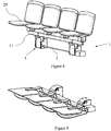
Figure 8 : Drive with the carrier beam with the chairs in the operating position -
Figure 9 : Drive with the carrier beam with the chairs in the folded position - The invention is described in more detail hereinbelow.
- The technical problem is solved by a
drive 1 for driving a carrier beam with chairs or a railing from a folded position into an operating position and vice versa, comprising: - a
fluid cylinder 2, - a
tow bar 3 connected with one end with thepiston rod 4 of the fluid cylinder, - at least two
drive mechanisms 5 arranged along the axle of thetow bar 3 at a mutual distance, each of them comprising:- a
housing 6 with acover 7, - a
main axle 8 mounted within thehousing 6 by means of aborehole 18, - a
switch leg 9 fixed on themain axle 8 and provided with aclamp 10, with which thecarrier beam 11 with chairs is fastenable, - at least one
torsion spring 12 arranged around themain axle 8 and connected with one end with thehousing 6 and with the other end with theswitch leg 9, - an
auxiliary axle 13 arranged within theswitch leg 9 in parallel to themain axle 8, yet at a distance from it, and - a
scissors mechanism 14 comprising short 15 andlong forks 16, wherein thelong fork 16 is connected with one end with thetow bar 3 and connected with the other end with theauxiliary axle 13, and theshort fork 15 is connected with one end in a Cardan-shaft manner with thehousing 6 through aring 17 rotatable around the axis of thetow bar 3 and with the other end with thelong fork 16 such that the distance between the connection of thelong fork 16 with thetow bar 3 and the mutual connection of bothforks short fork 15 with thering 17 and the mutual connection of bothforks
- a
- The
torsion spring 12 is pre-stressed to compensate for the weight of thecarrier beam 11 with chairs when the latter is arranged on the drive, wherewith the lifting of theswitch leg 9 from the folded position into the operating position is facilitated. - The connection of the
tow bar 3 and thepiston rod 4 of the fluid cylinder may be formed by means of a thread and a counter nut. - The borehole 18 in the
housing 6 of the drive mechanism for receiving themain axle 8 on each side of the main axle has an additionalfirst recess 19 extending downwards between the front edge of the borehole and the centre of theborehole 18. In the area where the main axle is connected with the housing, themain axle 8 which is preferably formed as a tube is provided with anotherrecess 20 that comprises at least 1/4 to 1/3 of the circumference of themain axle 8. Themain axle 8 is fastened in theswitch leg 9 such that thesecond recess 20 engages thefirst recess 19 when the switch leg is in the operating position. The first and the second recess are shaped in a way to prevent lowering of themain axle 8 while theswitch leg 9 is lifted to the operating position, although the forces transferred from thescissors mechanism 14 force it to this position. Only when the final operating position of theswitch leg 9 has been achieved, the first 19 and thesecond recess 20 engage each other. - The
switch leg 9 and/or thehousing 6 of the drive mechanism is provided with at least onetab switch leg 9, can engage agroove housing 6 of the drive mechanism or theswitch leg 9, respectively. It goes without saying that the grooves and tabs can be formed in a variety of ways. One embodiment discloses afirst groove 24 formed in the upper edge of a side of thehousing 6 of the drive mechanism and afirst tab 22 formed on the edge of theswitch leg 9 in the shape of a projection. A second embodiment discloses asecond groove 23 formed in anattachment 25 in the interior of thehousing 6 of the drive mechanism and asecond tab 21 formed on the lower edge of a side of theswitch leg 9 when the latter is in the operating position. There is preferably a plurality of tab and groove pairs. The pairs of tabs and the pairs of grooves are further preferably arranged along themain axle 8 at a mutual distance such that the loads of the main axle during the operation of the drive are smallest possible and that the clearance in the drive is not so expressed. - The
housing 6 may further be equipped with astop 26 and theswitch leg 9 may be equipped with aprojection 27 that prevents theswitch leg 9 from swivelling beyond the operating position. - The
switch leg 9 may be provided with a plurality ofholes 28 arranged radially around themain axle 8 and engaging with one end of thetorsion spring 12. By switching betweenvarious holes 28, the pre-stressing of thetorsion spring 12 can be adjusted. The torsion spring is preferably mounted into thehousing 6 and theswitch leg 9 such that the ends of thetorsion spring 12, while the switch leg is in the operating position, are arranged substantially horizontally, which facilitates thefluid cylinder 2 to lift themain axle 8 from thefirst recess 19 when lowering the chairs. - The
fluid cylinder 2 can be selected among a pneumatic or a hydraulic cylinder. In case of a hydraulic cylinder, a mechanical clutch is arranged between the hydraulic cylinder and the tow bar. - The invention further refers to telescopic seating comprising at least one above-indicated
drive 1 for driving acarrier beam 11 withchairs 29 or a railing from a folded position into an operating position and vice versa, a drive for moving the seating rows and at least onecarrier beam 11 withchairs 29. A seat surface of thechair 29 is preferably pivotally connected with the back rest by way of a pre-stressed spring, such that the seat surface of the chair and the back rest of the chair are parallel to each other both in the folded and the operating positions of the switch leg. In this case, each spectator unfolds the seat surface of the chair into a horizontal position before sitting on the chair. - Telescopic seating may further be provided with end switches to control the end positions of the folded chairs and/or railing, which switches alternately exclude the drives of the chairs and/or railings and the drives for extracting the seating in order to prevent collision between a chair or the railing and the desk of the seating. The drive for folding the seating may not turn on if all chairs are not folded on the desk. An end switch is used on each drive of the chairs and/or railing and is preferably arranged on the fluid cylinder. And vice versa, the lifting of the chairs may not turn on if the seating is not fully extracted.
- The power supply line for supplying the fluid cylinders may further be provided with a pressure switch controlling whether the end operating position of the chairs and/or railing has been reached. The control of the working position of the chairs and/or railing is only for information purposes, namely for the user to know that the method of setting the chairs and/or railing has been completed.
Claims (13)
- A drive (1) for driving a carrier beam (11) with chairs or a railing from a folded position into an operating position and vice versa, comprising:- a fluid cylinder (2),- a tow bar (3) connected with one end with the piston rod (4) of the fluid cylinder,- at least two drive mechanisms (5) arranged along the axle of the tow bar (3) at a mutual distance, each of them comprising:- a housing (6) with a cover (7),- a main axle (8) mounted within the housing (6) by means of a borehole (18),- a switch leg (9) fixed on the main axle (8) and provided with a clamp (10), with which the carrier beam (11) with chairs is fastenable,- at least one torsion spring (12) arranged around the main axle (8) and connected with one end with the housing (6) and with the other end with the switch leg (9),- an auxiliary axle (13) arranged within the switch leg (9) in parallel to the main axle (8), yet at a distance from it, and- a scissors mechanism (14) comprising short (15) and long forks (16), wherein the long fork (16) is connected with one end with the tow bar (3) and connected with the other end with the auxiliary axle (13), and the short fork (15) is connected with one end in a Cardan-shaft manner with the housing (6) by means of a ring (17) rotatable around the axis of the tow bar (3) and with the other end with the long fork (16) such that the distance between the connection of the long fork (16) with the tow bar (3) and the mutual connection of both forks (15, 16) equals the distance between the connection of the short fork (15) with the ring (17) and the mutual connection of both forks (15, 16).
- Drive (1) according to claim 1, characterized in that the borehole (18) in the housing (6) of the drive mechanism for receiving the main axle (8) is provided on each side of the main axle with an additional first recess (19) extending downwards between the front edge of the borehole and the centre of the borehole (18) and that the main axle (8) which is preferably formed as a tube is provided in the area, in which the main axle is connected with the housing, with another recess (20) that comprises at least 1/4 to 1/3 of the circumference of the main axle (8).
- Drive (1) according to any of preceding claims, characterized in that the switch leg (9) and/or the housing (6) of the drive mechanism is provided with at least one tab (21, 22) that, in the operating position of the switch leg (9), can engage a groove (23, 24) formed in the housing (6) of the drive mechanism and/or the switch leg (9).
- Drive (1) according to claim 3, characterized in that the tabs (21, 22) and the grooves (23, 24) are formed in pairs, wherein the pairs of tabs and the pairs of grooves are arranged along the main axle (8) at a distance from each other.
- Drive (1) according to any of preceding claims, characterized in that the housing (6) is equipped with a stop (26) and the switch leg (9) is equipped with a projection (27) to prevent the switch leg (9) from swivelling beyond the operating position.
- Drive (1) according to any of preceding claims, characterized in that the connection of the tow bar (3) and the piston rod (4) of the fluid cylinder is formed by means of a thread and a counter nut.
- Drive (1) according to any of preceding claims, characterized in that the torsion spring (12) is pre-stressed to facilitate lifting of the switch leg (9) from the folded position to the operating position.
- Drive (1) according to any of preceding claims, characterized in that the switch leg (9) is provided with a plurality of holes (28) arranged radially around the main axle (8) and engaging one end of the torsion spring (12), such that switching between various holes (28) allows adjustment of the pre-stressing of the torsion spring (12).
- Drive (1) according to any of preceding claims, characterized in that the torsion spring (12) is mounted into the housing (6) and the switch leg (9) such that the ends of the torsion spring (12), while the switch leg is in the operating position, are arranged substantially horizontally.
- Drive (1) according to any of preceding claims, characterized in that the fluid cylinder (2) is selected between a pneumatic or a hydraulic cylinder.
- Telescopic seating comprising at least one drive (1) according to any of preceding claims, a drive for moving the seating rows and at least one carrier beam (11) with chairs (29) and/or a railing.
- Telescopic seating according to claim 11, characterized in that a seat surface of the chair (29) is pivotally connected with a back rest of the chair by way of a pre-stressed spring.
- Telescopic seating according to claim 11 or 12, characterized in that it is further provided with end switches to control the end positions of the chairs and/or railing, which switches mutually exclude the drives of the chairs and/or railings and the drives for extracting the seating.
Applications Claiming Priority (1)
| Application Number | Priority Date | Filing Date | Title |
|---|---|---|---|
| SI201700343A SI25582A (en) | 2017-12-28 | 2017-12-28 | A drive for folding chairs on telescopic stand and telescopic stand comprise such a drive |
Publications (1)
| Publication Number | Publication Date |
|---|---|
| EP3505012A1 true EP3505012A1 (en) | 2019-07-03 |
Family
ID=64664557
Family Applications (1)
| Application Number | Title | Priority Date | Filing Date |
|---|---|---|---|
| EP18000950.8A Withdrawn EP3505012A1 (en) | 2017-12-28 | 2018-12-10 | Drive for folding chairs on telescopic seating and telescopic seating comprising such a drive |
Country Status (2)
| Country | Link |
|---|---|
| EP (1) | EP3505012A1 (en) |
| SI (1) | SI25582A (en) |
Cited By (1)
| Publication number | Priority date | Publication date | Assignee | Title |
|---|---|---|---|---|
| CN112983059A (en) * | 2021-02-25 | 2021-06-18 | 深圳市领先康体实业有限公司 | Stand lifting module |
Citations (4)
| Publication number | Priority date | Publication date | Assignee | Title |
|---|---|---|---|---|
| US4155202A (en) | 1978-04-03 | 1979-05-22 | American Seating Company | Telescoping seating system with automatically folding chairs |
| US4294048A (en) | 1980-02-04 | 1981-10-13 | Hussey Manufacturing Co., Inc. | Apparatus for supporting pivotally mounted seats |
| US4557080A (en) | 1984-07-18 | 1985-12-10 | American Seating Company | Automatic seating for telescoping row systems |
| US4850159A (en) | 1985-08-14 | 1989-07-25 | Irwin Seating Company | Collapsible seating system with automatically folding seats |
-
2017
- 2017-12-28 SI SI201700343A patent/SI25582A/en active IP Right Grant
-
2018
- 2018-12-10 EP EP18000950.8A patent/EP3505012A1/en not_active Withdrawn
Patent Citations (4)
| Publication number | Priority date | Publication date | Assignee | Title |
|---|---|---|---|---|
| US4155202A (en) | 1978-04-03 | 1979-05-22 | American Seating Company | Telescoping seating system with automatically folding chairs |
| US4294048A (en) | 1980-02-04 | 1981-10-13 | Hussey Manufacturing Co., Inc. | Apparatus for supporting pivotally mounted seats |
| US4557080A (en) | 1984-07-18 | 1985-12-10 | American Seating Company | Automatic seating for telescoping row systems |
| US4850159A (en) | 1985-08-14 | 1989-07-25 | Irwin Seating Company | Collapsible seating system with automatically folding seats |
Cited By (1)
| Publication number | Priority date | Publication date | Assignee | Title |
|---|---|---|---|---|
| CN112983059A (en) * | 2021-02-25 | 2021-06-18 | 深圳市领先康体实业有限公司 | Stand lifting module |
Also Published As
| Publication number | Publication date |
|---|---|
| SI25582A (en) | 2019-07-31 |
Similar Documents
| Publication | Publication Date | Title |
|---|---|---|
| US3858688A (en) | Self-contained mobile extendable tower | |
| US5145029A (en) | Self-storing maintenance stand for a scissor lift aerial work platform | |
| US8425155B2 (en) | Jacking system for a leg of a jack-up platform | |
| CA2795097C (en) | Movable stand with variable viewing angles | |
| JP4395491B2 (en) | Heavy lifting device and heavy lifting system | |
| US20140041963A1 (en) | Deployable Hybrid Mobile Elevating Access Platform | |
| CA2235187A1 (en) | Automotive lift | |
| US6253502B1 (en) | Van with extensible boom | |
| SE461209B (en) | DEVICE AT A VEHICLE-ADJUSTED LIFT | |
| US4833972A (en) | Wheeled table floor lock apparatus | |
| EP3947137B1 (en) | Gangway having self-raising assembly | |
| USRE28455E (en) | Portable elevator working and load-lifting platform | |
| EP3505012A1 (en) | Drive for folding chairs on telescopic seating and telescopic seating comprising such a drive | |
| CN101670996A (en) | Hydraulic lifter | |
| AU2006338052A1 (en) | Lifting system | |
| CN105314500A (en) | Corridor elevator seat device | |
| US2877507A (en) | Mobile tiered assemblage | |
| CN106869826B (en) | A kind of oil-well rig dynamic catwalk and its drilling tool stowage | |
| US5732931A (en) | Mobile vehicle jack having an engageable support member | |
| CN212924194U (en) | Automatic escalator of automobile crane | |
| CN214044700U (en) | Special trolley for replacing current transformer of armored switch cabinet | |
| WO2002066359A1 (en) | Elevator device | |
| WO2014060721A1 (en) | Base unit for a vehicle | |
| US4302004A (en) | Mobile amusement ride | |
| RU2570679C1 (en) | Hydraulic drive mainly used for mobile antenna unit with lifting element |
Legal Events
| Date | Code | Title | Description |
|---|---|---|---|
| PUAI | Public reference made under article 153(3) epc to a published international application that has entered the european phase |
Free format text: ORIGINAL CODE: 0009012 |
|
| AK | Designated contracting states |
Kind code of ref document: A1 Designated state(s): AL AT BE BG CH CY CZ DE DK EE ES FI FR GB GR HR HU IE IS IT LI LT LU LV MC MK MT NL NO PL PT RO RS SE SI SK SM TR |
|
| AX | Request for extension of the european patent |
Extension state: BA ME |
|
| RAP1 | Party data changed (applicant data changed or rights of an application transferred) |
Owner name: ELAN INVENTA, DRUZBA ZA PROIZVODNJO IN STORITVE, D |
|
| STAA | Information on the status of an ep patent application or granted ep patent |
Free format text: STATUS: THE APPLICATION IS DEEMED TO BE WITHDRAWN |
|
| 18D | Application deemed to be withdrawn |
Effective date: 20200104 |