EP3504958A1 - Dynamic combine fire risk index and display - Google Patents
Dynamic combine fire risk index and display Download PDFInfo
- Publication number
- EP3504958A1 EP3504958A1 EP18248108.5A EP18248108A EP3504958A1 EP 3504958 A1 EP3504958 A1 EP 3504958A1 EP 18248108 A EP18248108 A EP 18248108A EP 3504958 A1 EP3504958 A1 EP 3504958A1
- Authority
- EP
- European Patent Office
- Prior art keywords
- risk
- combine
- controller
- fire
- estimated
- Prior art date
- Legal status (The legal status is an assumption and is not a legal conclusion. Google has not performed a legal analysis and makes no representation as to the accuracy of the status listed.)
- Granted
Links
Images




Classifications
-
- A—HUMAN NECESSITIES
- A01—AGRICULTURE; FORESTRY; ANIMAL HUSBANDRY; HUNTING; TRAPPING; FISHING
- A01D—HARVESTING; MOWING
- A01D41/00—Combines, i.e. harvesters or mowers combined with threshing devices
- A01D41/12—Details of combines
- A01D41/127—Control or measuring arrangements specially adapted for combines
-
- A—HUMAN NECESSITIES
- A01—AGRICULTURE; FORESTRY; ANIMAL HUSBANDRY; HUNTING; TRAPPING; FISHING
- A01B—SOIL WORKING IN AGRICULTURE OR FORESTRY; PARTS, DETAILS, OR ACCESSORIES OF AGRICULTURAL MACHINES OR IMPLEMENTS, IN GENERAL
- A01B79/00—Methods for working soil
- A01B79/005—Precision agriculture
-
- A—HUMAN NECESSITIES
- A01—AGRICULTURE; FORESTRY; ANIMAL HUSBANDRY; HUNTING; TRAPPING; FISHING
- A01D—HARVESTING; MOWING
- A01D41/00—Combines, i.e. harvesters or mowers combined with threshing devices
- A01D41/12—Details of combines
- A01D41/1252—Anti-dust devices
-
- A—HUMAN NECESSITIES
- A01—AGRICULTURE; FORESTRY; ANIMAL HUSBANDRY; HUNTING; TRAPPING; FISHING
- A01D—HARVESTING; MOWING
- A01D91/00—Methods for harvesting agricultural products
-
- A—HUMAN NECESSITIES
- A01—AGRICULTURE; FORESTRY; ANIMAL HUSBANDRY; HUNTING; TRAPPING; FISHING
- A01F—PROCESSING OF HARVESTED PRODUCE; HAY OR STRAW PRESSES; DEVICES FOR STORING AGRICULTURAL OR HORTICULTURAL PRODUCE
- A01F12/00—Parts or details of threshing apparatus
- A01F12/58—Control devices; Brakes; Bearings
-
- A—HUMAN NECESSITIES
- A62—LIFE-SAVING; FIRE-FIGHTING
- A62C—FIRE-FIGHTING
- A62C3/00—Fire prevention, containment or extinguishing specially adapted for particular objects or places
- A62C3/07—Fire prevention, containment or extinguishing specially adapted for particular objects or places in vehicles, e.g. in road vehicles
-
- G—PHYSICS
- G06—COMPUTING OR CALCULATING; COUNTING
- G06Q—INFORMATION AND COMMUNICATION TECHNOLOGY [ICT] SPECIALLY ADAPTED FOR ADMINISTRATIVE, COMMERCIAL, FINANCIAL, MANAGERIAL OR SUPERVISORY PURPOSES; SYSTEMS OR METHODS SPECIALLY ADAPTED FOR ADMINISTRATIVE, COMMERCIAL, FINANCIAL, MANAGERIAL OR SUPERVISORY PURPOSES, NOT OTHERWISE PROVIDED FOR
- G06Q10/00—Administration; Management
- G06Q10/04—Forecasting or optimisation specially adapted for administrative or management purposes, e.g. linear programming or "cutting stock problem"
-
- G—PHYSICS
- G06—COMPUTING OR CALCULATING; COUNTING
- G06Q—INFORMATION AND COMMUNICATION TECHNOLOGY [ICT] SPECIALLY ADAPTED FOR ADMINISTRATIVE, COMMERCIAL, FINANCIAL, MANAGERIAL OR SUPERVISORY PURPOSES; SYSTEMS OR METHODS SPECIALLY ADAPTED FOR ADMINISTRATIVE, COMMERCIAL, FINANCIAL, MANAGERIAL OR SUPERVISORY PURPOSES, NOT OTHERWISE PROVIDED FOR
- G06Q10/00—Administration; Management
- G06Q10/06—Resources, workflows, human or project management; Enterprise or organisation planning; Enterprise or organisation modelling
- G06Q10/063—Operations research, analysis or management
- G06Q10/0635—Risk analysis of enterprise or organisation activities
-
- G—PHYSICS
- G06—COMPUTING OR CALCULATING; COUNTING
- G06Q—INFORMATION AND COMMUNICATION TECHNOLOGY [ICT] SPECIALLY ADAPTED FOR ADMINISTRATIVE, COMMERCIAL, FINANCIAL, MANAGERIAL OR SUPERVISORY PURPOSES; SYSTEMS OR METHODS SPECIALLY ADAPTED FOR ADMINISTRATIVE, COMMERCIAL, FINANCIAL, MANAGERIAL OR SUPERVISORY PURPOSES, NOT OTHERWISE PROVIDED FOR
- G06Q50/00—Information and communication technology [ICT] specially adapted for implementation of business processes of specific business sectors, e.g. utilities or tourism
- G06Q50/02—Agriculture; Fishing; Forestry; Mining
Definitions
- the invention relates to a combine that dynamically computes an estimated fire risk based on various risk factors, and reports this estimated fire risk to the operator of the combine.
- Harvesters e.g. combines are used to harvest crops. Operations performed by these combines include threshing and separating grain from crop residue, which is then expelled from the combine through a residue system. Such harvesting methods produce small crop particles that may become airborne and potentially enter the air intake of the combine engine compartment and stick to the various engine components. Combine engine components may become hot during harvesting, which can increase the risk of igniting the crop particles.
- An embodiment includes a combine comprising an engine compartment comprising an engine for propelling the combine, a feeder housing for receiving cut crop, a separating system for threshing the cut crop to produce grain and residue, a residue chopper for chopping the residue, and a controller.
- the controller is configured to estimate risk factors that correlate to a risk of fire in the engine compartment due to airborne particles created by at least one of the cut crop, the separating system or the residue chopper, estimate a fire risk based on the risk factors, and implement corrective action based on the estimated fire risk.
- An embodiment includes a method for controlling a combine including an engine compartment comprising an engine for propelling the combine, a feeder housing for receiving cut crop, a separating system for threshing the cut crop to produce grain and residue, a residue chopper for chopping the residue, and a controller.
- the method comprises determining, by the controller, risk factors that correlates to a risk of fire in the engine compartment due to airborne particles created by at least one of the cutter bar, the separating system or the residue chopper, estimating, by the controller, a fire risk based on the risk factors, and implementing, by the controller, corrective action based on the estimated fire risk.
- aspects of the invention provide methods and systems for operating a combine to automatically estimate a fire risk based on various risk factors, and indicate this estimated fire risk to the operator of the combine.
- ground refers to that part of the crop material which is threshed and separated from the discardable part of the crop material, which is referred to as non-grain crop material, material other than grain (MOG) or straw. Incompletely threshed crop material is referred to as "tailings.”
- forward refers to the direction of forward operative travel of the combine, but again, they should not be construed as limiting.
- longitudinal and “transverse” are determined with reference to the fore-and-aft direction of the agricultural combine and are equally not to be construed as limiting.
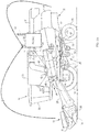
- FIG. 1A there is shown one embodiment of an agricultural harvester in the form of a combine 10, which generally includes a chassis 12, ground engaging wheels 14 and 16, a header 18, a feeder housing 20, an operator cab 22, a threshing and separating system 24, a cleaning system 26, a grain tank 28, and an unloading auger 30.
- Front wheels 14 are larger flotation type wheels, and rear wheels 16 are smaller steerable wheels. Motive force is selectively applied to front wheels 14 through a power plant in the form of a diesel engine 32 and a transmission (not shown).
- combine 10 is shown as including wheels, is also to be understood that combine 10 may include tracks, such as full tracks or half-tracks.
- Header 18 is mounted to the front of combine 10 and includes a cutter bar 34 for severing crops from a field during forward motion of combine 10.
- a rotatable reel 36 feeds the crop into header 18, and a double auger 38 feeds the severed crop laterally inwardly from each side toward feeder housing 20.
- Feeder housing 20 conveys the cut crop to threshing and separating system 24, and is selectively vertically movable using appropriate actuators, such as hydraulic cylinders (not shown).
- Threshing and separating system 24 is of the axial-flow type, and generally includes a rotor 40 at least partially enclosed by and rotatable within a corresponding perforated concave 42.
- the cut crops are threshed and separated by the rotation of rotor 40 within concave 42, and larger elements, such as stalks, leaves and the like are discharged from the rear of combine 10.
- Smaller elements of crop material including grain and non-grain crop material, including particles lighter than grain, such as chaff, dust and straw, are discharged through perforations of concave 42.
- Cleaning system 26 may include an optional pre-cleaning sieve 46, an upper sieve 48 (also known as a chaffer sieve), a lower sieve 50 (also known as a cleaning sieve), and a cleaning fan 52. Grain on sieves 46, 48 and 50 is subjected to a cleaning action by fan 52 which provides an airflow through the sieves to remove chaff and other impurities such as dust from the grain by making this material airborne for discharge from straw hood 54 of combine 10.
- Grain pan 44 and pre-cleaning sieve 46 oscillate in a fore-to-aft manner to transport the grain and finer non-grain crop material to the upper surface of upper sieve 48.
- Upper sieve 48 and lower sieve 50 are vertically arranged relative to each other, and likewise oscillate in a fore-to-aft manner to spread the grain across sieves 48, 50, while permitting the passage of cleaned grain by gravity through the openings of sieves 48, 50.
- Clean grain falls to a clean grain auger 56 positioned crosswise below and in front of lower sieve 50.
- Clean grain auger 56 receives clean grain from each sieve 48, 50 and from bottom pan 58 of cleaning system 26.
- Clean grain auger 56 conveys the clean grain laterally to a generally vertically arranged grain elevator 60 for transport to grain tank 28.
- Tailings from cleaning system 26 fall to a tailings auger trough 62.
- the tailings are transported via tailings auger 64 and return auger 66 to the upstream end of cleaning system 26 for repeated cleaning action.
- a pair of grain tank augers 68 at the bottom of grain tank 28 convey the clean grain laterally within grain tank 28 to unloading auger 30 for discharge from combine 10.
- Residue handling system 70 includes a chopper, a chopper pan, counter knives, a windrow door and a residue spreader.
- the chopper When combine 10 operating in the chopping and spreading mode, the chopper is set to a relatively high speed (e.g. 3,000 RPM), the counter knives may be engaged, the windrow door is closed and the residue spreader is running (e.g. rotating). This causes the non-grain crop material to be chopped in to pieces of approximately 6 inches or less and spread on the ground in a fairly uniform manner.
- the chopper is at a relatively low speed (e.g. 800 RPM), the counter knives are disengaged and the windrow door is open.
- the residue spreader may continue operation to spread only the chaff, with the crop material passing through the passageway created by the open windrow door.
- the combine also monitors both yield and loss of the grain to ensure efficient operation.
- Loss is generally defined as a percentage of grain lost. Loss includes grain that is accidentally blown by fan 52 into the straw hood 54 and ejected from the combine rather than collected in the tank.
- yield is generally defined as the amount of grain collected in the tank (e.g. bushels).
- Loss may be monitored by a loss sensor (not shown) that could be positioned within straw hood 54 (see FIG. 1A ).
- Yield may be monitored by a yield sensor (not shown) that could be positioned within grain tank 28 (see FIG. 1A ).
- Throughput is yet another metric that can be determined based on yield. As described above, yield is determined based on signals transmitted and received by yield sensor 115. Throughput is the amount of crop being processed by the combine at a given time. Generally, throughput can be computed by measuring yield over a time period. Both loss and throughput are risk factors that may be beneficial to controlling various components of the combine.
- Diesel engine 32 shown in FIG. 1A may include an air intake port 31, and an exhaust port 32.
- Air intake port 31 draws fresh air into the engine compartment. This fresh air is used to both cool engine components (not shown), and provide oxygen in the combustion chamber (not shown) of engine 32.
- Exhaust port 32 expels exhaust produced by engine 32.
- air intake port 31 may also draw in airborne crop particles into the engine compartment. These airborne particles are produced by crop that is threshed by header 18 via path 1, and by crop that is ejected from residue system 70 via path 2. Due to factors including oils (e.g. oils in the crop, or engine oil/grease), these airborne particles may stick to various components within the engine compartment (e.g. radiator, engine housing, transmission, etc.).
- oils e.g. oils in the crop, or engine oil/grease
- a buildup of these particles may occur. If a buildup is present within the engine compartment, various problems could result. For example, if the engine intake filter (not shown) is clogged, then the engine performance may suffer. In addition, it becomes more difficult to cool the engine, which could increase the internal temperature, and therefore the risk of igniting particles.
- residue system 70 includes a windrow door 104, a spreader chute 106, a windrow chute 108, spreader wheels 110, chopper 114 and chopper pan 116.
- Chopper 114 chops the crop that enters residue system 70. The chopped crop (including the particles) is then expelled either through windrow door 104 and windrow chute 108 via path 112A or through spreader wheels 110 via path 112B.
- windrow door 104, spreader wheels 110, and chopper 114 are electrically connected to a controller (e.g. programmable logic controller, micro-controller, etc.) located in the combine.
- the controller is programmable by the operator of the combine through a user (e.g. operator) interface, or through a remote computer (see Fig. 3 ).
- the operator for example, enters commands through the user interface.
- the controller sends control signals to the various actuators of residue handling system 70.
- the combine travels a certain pathway.
- the pathways shown in FIG. 2 are typical for a plot of land 202 that is to be harvested.
- the combine may employ residue system 70 to perform spreading and/or windrowing of the harvested crops at different locations of the field.
- the combine may start performing spreading along path 204. Once the combine reaches point 208, a turn is made and spreading is performed along path 206. Once the combine reaches point 210, a turn is made and spreading is performed along path 212. Finally, once the combine reaches point 214, a turn is made and windrowing is performed in a zig-zag pattern along path 216. In either mode, small particles produced by residue system 70, and by header 18 become airborne and enter the engine compartment where they build up over time.
- FIG. 3 shows an example of a system for controlling the combine and estimating fire risk.
- the system includes an interconnection between a control system 320 of combine 10, a remote PC 306 at location 308, and a remote server 302 through network 300 (e.g. Internet).
- network 300 e.g. Internet
- combine 10 does not have to be connected to other devices through a network.
- the controller of combine 10 can be a standalone system that receives operating instructions and other information through a user interface, or through a removable memory device (e.g. Flash Drive). Harvesting may also be tracked and aided by GPS receiver 312.
- various risk factors may be received either through the user interface, or through transceiver 322 (e.g. WiFi, Bluetooth, Cellular) from a remote source.
- the operator may use interface 304, or another entity (e.g. farm manager) may use PC 306 located at remote location 308 to enter information into the combine control system.
- Interface 304 and PC 306 generally allow the operator, or any other entity (e.g. farm manager), to view locally stored information from memory device 316 and/or download information from server 302 through network 300 via transceiver 322.
- the operator may select (via Interface 304 or PC 306) risk factors for estimating fire risk in the combine. Once these risk factors are selected, the operator can begin harvesting.
- Combine controller 310 estimates and monitors the fire risk based on these selected risk factors. If a fire risk is estimated to be above a set threshold (e.g. probability), the combine may implement risk reduction action such as notifying the operator, requesting the operator to perform some action to reduce the estimated fire risk, and/or automatically controlling the combine in a manner to reduce the estimated fire risk.
- a set threshold e.g. probability
- the risk factors described above may be selected and displayed on the interface 304.
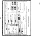
- An example of interface 304 is shown in FIG. 4 wherein various parameters and data are displayed to the operator through a graphical user interface (GUI) 400.
- GUI graphical user interface
- These may include a view of the map 402 with designated harvesting zones, land grade (not shown), current operational mode, throughput/loss, operational parameters/states for the spreader wheels, chopper, counter knives, windrow door, etc., fire risk and fire risk settings for setting fire risk factors.
- These parameters as well as the fire risk factors may be set or modified by the operator prior to harvesting or during harvesting. For example, the operator can use a stylus or their finger on the touchscreen modify the fire risk settings.
- FIG. 5A show a flowchart for setting fire risk factors and estimating/reporting the fire risk for the combine.
- different types of inputs may be considered. These include internal inputs and external inputs.
- the internal inputs which may be input (step 502) by the operator via interface 304 or by combine sensors 318, include but are not limited to the type of crop being harvested, ambient temperature, relative humidity, time of day, engine load, exhaust gas temperature, wind direction and speed, time since last vehicle cleaning, and GPS position.
- the external inputs, which are input (step 504) from remote sources via network 300 include but are not limited to local weather forecasts, and the local fire weather outlook from the National Oceanic and Atmospheric Association (NOAA). These external inputs may be received wirelessly by the combine via transceiver 322, or may be input by the operator via a memory device inserted into the combine interface.
- NOAA National Oceanic and Atmospheric Association
- controller 310 applies weighting factors. For example, some inputs (e.g. type of crop being harvested, ambient temperature, relative humidity) may be considered more important than other risk factors (e.g. wind direction/speed) for estimating fire risk.
- the controller accounts for this by setting weighting factors based on their importance (e.g. more important risk factors for estimating fire risk are assigned higher weights).
- each risk factor may be normalized between a value of 0-1 so that they can be compared to each other. These normalized values may then be multiplied by a weighting value between 0-1.
- exhaust temperature may be normalized between 0-1 where 0 is equivalent to the minimum exhaust temperature, and 1 is equivalent to the maximum exhaust temperature. If the detected exhaust temperature during operation is in the middle of the range, then it may be given a value of 0.5. This value of 0.5 may then be multiplied by a weighting factor (e.g. 0.8) if exhaust temperature is considered an important factor in estimating fire risk. If exhaust temperature is not as important, then 0.5 may be multiplied by a smaller weighting factor of (e.g. 0.3).
- a weighting factor e.g. 0.8
- controller 310 combines (see step 508) these weighted values to estimate the fire risk. For example, the weighted values may be summed together to estimate fire risk. In one example, assume that ten risk factors are used to estimate fire risk. These ten risk factors (after normalization), when summed, would result in a number in the range of 0-10 depending on their weighting. This summation could then be normalized between 0%-100%, where 0 is equivalent to 0% fire risk and 10 is equivalent to 100% fire risk.
- FIG. 5B An example of estimating fire risk by weighting certain risk factors is shown in the table of FIG. 5B .
- five risk factors are considered. These risk factors include type of crop, ambient temperature, NOAA fire risk, ambient humidity, and exhaust temperature.
- Column 532 shows crop types C1-CN having predetermined estimated risks RISKC1-RISKCN.
- Column 534 shows ambient temperatures AT1-ATN having predetermined estimated risks RISKAT1-RISKATN.
- Column 536 shows NOAA values NA1-NAN having predetermined estimated risks RISKNA1-RISKNAN.
- Column 538 shows humidity values H1-HN having predetermined estimated risks RISKH1-RISKHN.
- Column 540 shows exhaust temperatures ET1-ETN having predetermined estimated risks RISKET1-RISKETN.
- Estimated risk values RISKC1-RISKCN, RISKAT1-RISKATN, RISKNA1-RISKNAN, RISKH1-RISKHN and RISKET1-RISKETN may be set by the operator of the combine, by the farm owner/operator, by the manufacturer of the combine or some other third party. In addition, these risk values may be estimated based on experience, research and other factors.
- controller 310 accesses table 530 and extracts the risk associated with the type of crop, ambient temperature, NOAA fire risk, ambient humidity, and exhaust temperature currently measured. These values are then weighted and summed to produce the estimated fire risk.
- the estimated fire risk may be displayed (step 510) to the operator through interface 304.
- Controller 310 may also estimate (step 512) if the fire risk is higher than a predetermined threshold (i.e. higher than usual). This estimation may be based on previous experience, or any number of risk factors. If the fire risk is estimated not to be higher than the predetermined threshold (i.e. not higher than usual), then harvesting continues and the process described above is eventually repeated periodically based on timer 518. However, if the fire risk is estimated to be higher than the predetermined threshold (i.e. higher than usual), then controller 310 notifies the user (step 514).
- This notification may be issued in a number of different manners including, but not limited to an audible and/or visual alarm, prompts on interface 304, transmitted emails, transmitted text messages, etc.
- interface 304 may emit a buzzer sound and flash the screen to let the operator know of the estimated fire risk.
- a text message may be automatically transmitted to the operator and/or a remote user.
- the predetermined threshold may be a value set by the operator of the combine, by the farm owner/operator, by the manufacturer of the combine or some other third party. This predetermined threshold may be estimated based on experience, research and other factors.
- controller 310 may also display prompts. These prompts may request certain actions to be taken by the operator, including but not limited to slowing down to reduce engine load, and stopping to clean the engine compartment and other combine compartments.
- controller 310 may automatically control the combine to reduce the estimated fire risk. Controller 310 may automatically reduce harvesting speed to reduce engine load and therefore operating temperature. If the estimated fire risk increases above a certain level, controller 310 may also stop the combine harvesting operation and force the operator to clean the engine compartment before resuming.
- controller 310 may also create a log of operations. Controller 310 may store (step 516) the estimated fire risk over time, risk factors being considered when estimating the fire risk, prompts and alarms issued to the operator, and how the operator responded to the alarms and prompts. This log may then be uploaded to a removable memory device, or to another compute/server via network 300. This allows the operation of the combine to be monitored and reviewed by other entities such as the manufacturer, farm manager, etc.
- the fire risk is an estimation (not proof positive) of the chance that a fire could ignite given certain known conditions.
- the accuracy of this estimation is dependent on a number of variables including the risk factors described above and the manner in which they are weighted and combined.
- other variables may also contribute to the fire risk. These may include operator error (e.g. deficient inspection/cleaning procedures, inadequate maintenance, etc.), unforeseen conditions (e.g. birds nest in the engine compartment, etc.) as well as other variables that affect the risk of fire.
- Steps 502-518 shown in FIG. 5A may be performed by controller 310 upon loading and executing software code or instructions which are tangibly stored on a tangible computer readable medium 316, such as on a magnetic medium, e.g., a computer hard drive, an optical medium, e.g., an optical disc, solid-state memory, e.g., flash memory, or other storage media known in the art.
- a tangible computer readable medium 316 such as on a magnetic medium, e.g., a computer hard drive, an optical medium, e.g., an optical disc, solid-state memory, e.g., flash memory, or other storage media known in the art.
- any of the functionality performed by the controller 310 described herein, such as the steps shown in FIG. 5A are implemented in software code or instructions which are tangibly stored on a tangible computer readable medium.
- the controller 310 may perform any of the functionality of the controller 310 described herein, including the steps shown in FIG. 5A described herein.
- software code or “code” used herein refers to any instructions or set of instructions that influence the operation of a computer or controller. They may exist in a computer-executable form, such as machine code, which is the set of instructions and data directly executed by a computer's central processing unit or by a controller, a human-understandable form, such as source code, which may be compiled in order to be executed by a computer's central processing unit or by a controller, or an intermediate form, such as object code, which is produced by a compiler.
- the term "software code” or “code” also includes any human-understandable computer instructions or set of instructions, e.g., a script, that may be executed on the fly with the aid of an interpreter executed by a computer's central processing unit or by a controller.
Landscapes
- Life Sciences & Earth Sciences (AREA)
- Environmental Sciences (AREA)
- Engineering & Computer Science (AREA)
- Mechanical Engineering (AREA)
- Soil Sciences (AREA)
- Combines (AREA)
Abstract
Description
- The invention relates to a combine that dynamically computes an estimated fire risk based on various risk factors, and reports this estimated fire risk to the operator of the combine.
- Harvesters (e.g. combines) are used to harvest crops. Operations performed by these combines include threshing and separating grain from crop residue, which is then expelled from the combine through a residue system. Such harvesting methods produce small crop particles that may become airborne and potentially enter the air intake of the combine engine compartment and stick to the various engine components. Combine engine components may become hot during harvesting, which can increase the risk of igniting the crop particles.
- An embodiment includes a combine comprising an engine compartment comprising an engine for propelling the combine, a feeder housing for receiving cut crop, a separating system for threshing the cut crop to produce grain and residue, a residue chopper for chopping the residue, and a controller. The controller is configured to estimate risk factors that correlate to a risk of fire in the engine compartment due to airborne particles created by at least one of the cut crop, the separating system or the residue chopper, estimate a fire risk based on the risk factors, and implement corrective action based on the estimated fire risk.
- An embodiment includes a method for controlling a combine including an engine compartment comprising an engine for propelling the combine, a feeder housing for receiving cut crop, a separating system for threshing the cut crop to produce grain and residue, a residue chopper for chopping the residue, and a controller. The method comprises determining, by the controller, risk factors that correlates to a risk of fire in the engine compartment due to airborne particles created by at least one of the cutter bar, the separating system or the residue chopper, estimating, by the controller, a fire risk based on the risk factors, and implementing, by the controller, corrective action based on the estimated fire risk.
-
-
FIG. 1A is a side view of a combine, according to an embodiment of the invention. -
FIG.1B is a section view of a combine residue system, according to an embodiment of the invention. -
FIG. 2 is a typical path traversed by the combine during harvesting, according to an embodiment of the invention. -
FIG. 3 is a system view of network based communication between the combine controller, a remote personal computer and a server, according to an embodiment of the invention. -
FIG. 4 is an illustration of a user interface for monitoring and controlling the combine, according to an embodiment of the invention. -
FIG. 5A is a flowchart of steps for estimating fire risk based on various risk factors, according to an embodiment of the invention. -
FIG. 5B is a table for estimating fire risk based on the various risk factors, according to an embodiment of the invention. - Aspects of the invention provide methods and systems for operating a combine to automatically estimate a fire risk based on various risk factors, and indicate this estimated fire risk to the operator of the combine.
- The terms "grain," "straw," and "tailings" are used principally throughout this specification for convenience but it is to be understood that these terms are not intended to be limiting. Thus "grain" refers to that part of the crop material which is threshed and separated from the discardable part of the crop material, which is referred to as non-grain crop material, material other than grain (MOG) or straw. Incompletely threshed crop material is referred to as "tailings." Also the terms "forward," "rearward," "left," and "right", when used in connection with the agricultural harvester (e.g. combine) and/or components thereof are usually determined with reference to the direction of forward operative travel of the combine, but again, they should not be construed as limiting. The terms "longitudinal" and "transverse" are determined with reference to the fore-and-aft direction of the agricultural combine and are equally not to be construed as limiting.
- Referring now to the drawings, and more particularly to
FIG. 1A , there is shown one embodiment of an agricultural harvester in the form of acombine 10, which generally includes achassis 12, groundengaging wheels header 18, afeeder housing 20, anoperator cab 22, a threshing and separatingsystem 24, acleaning system 26, agrain tank 28, and anunloading auger 30. -
Front wheels 14 are larger flotation type wheels, andrear wheels 16 are smaller steerable wheels. Motive force is selectively applied tofront wheels 14 through a power plant in the form of adiesel engine 32 and a transmission (not shown). Althoughcombine 10 is shown as including wheels, is also to be understood that combine 10 may include tracks, such as full tracks or half-tracks. -
Header 18 is mounted to the front ofcombine 10 and includes acutter bar 34 for severing crops from a field during forward motion ofcombine 10. Arotatable reel 36 feeds the crop intoheader 18, and adouble auger 38 feeds the severed crop laterally inwardly from each side towardfeeder housing 20.Feeder housing 20 conveys the cut crop to threshing and separatingsystem 24, and is selectively vertically movable using appropriate actuators, such as hydraulic cylinders (not shown). - Threshing and separating
system 24 is of the axial-flow type, and generally includes arotor 40 at least partially enclosed by and rotatable within a corresponding perforated concave 42. The cut crops are threshed and separated by the rotation ofrotor 40 within concave 42, and larger elements, such as stalks, leaves and the like are discharged from the rear ofcombine 10. Smaller elements of crop material including grain and non-grain crop material, including particles lighter than grain, such as chaff, dust and straw, are discharged through perforations of concave 42. - Grain which has been separated by the threshing and separating
assembly 24 falls onto agrain pan 44 and is conveyed towardcleaning system 26.Cleaning system 26 may include an optional pre-cleaningsieve 46, an upper sieve 48 (also known as a chaffer sieve), a lower sieve 50 (also known as a cleaning sieve), and acleaning fan 52. Grain onsieves fan 52 which provides an airflow through the sieves to remove chaff and other impurities such as dust from the grain by making this material airborne for discharge fromstraw hood 54 of combine 10. Grainpan 44 and pre-cleaningsieve 46 oscillate in a fore-to-aft manner to transport the grain and finer non-grain crop material to the upper surface of upper sieve 48. Upper sieve 48 andlower sieve 50 are vertically arranged relative to each other, and likewise oscillate in a fore-to-aft manner to spread the grain acrosssieves 48, 50, while permitting the passage of cleaned grain by gravity through the openings ofsieves 48, 50. - Clean grain falls to a
clean grain auger 56 positioned crosswise below and in front oflower sieve 50.Clean grain auger 56 receives clean grain from eachsieve 48, 50 and frombottom pan 58 ofcleaning system 26.Clean grain auger 56 conveys the clean grain laterally to a generally vertically arrangedgrain elevator 60 for transport tograin tank 28. Tailings fromcleaning system 26 fall to atailings auger trough 62. The tailings are transported viatailings auger 64 and returnauger 66 to the upstream end ofcleaning system 26 for repeated cleaning action. A pair ofgrain tank augers 68 at the bottom ofgrain tank 28 convey the clean grain laterally withingrain tank 28 to unloadingauger 30 for discharge fromcombine 10. - The non-grain crop material proceeds through a
residue handling system 70.Residue handling system 70 includes a chopper, a chopper pan, counter knives, a windrow door and a residue spreader. When combine 10 operating in the chopping and spreading mode, the chopper is set to a relatively high speed (e.g. 3,000 RPM), the counter knives may be engaged, the windrow door is closed and the residue spreader is running (e.g. rotating). This causes the non-grain crop material to be chopped in to pieces of approximately 6 inches or less and spread on the ground in a fairly uniform manner. In contrast, whencombine 10 is operating in the windrow mode, the chopper is at a relatively low speed (e.g. 800 RPM), the counter knives are disengaged and the windrow door is open. The residue spreader may continue operation to spread only the chaff, with the crop material passing through the passageway created by the open windrow door. - The combine also monitors both yield and loss of the grain to ensure efficient operation. Loss is generally defined as a percentage of grain lost. Loss includes grain that is accidentally blown by
fan 52 into thestraw hood 54 and ejected from the combine rather than collected in the tank. In contrast, yield is generally defined as the amount of grain collected in the tank (e.g. bushels). Loss may be monitored by a loss sensor (not shown) that could be positioned within straw hood 54 (seeFIG. 1A ). Yield may be monitored by a yield sensor (not shown) that could be positioned within grain tank 28 (seeFIG. 1A ). Throughput is yet another metric that can be determined based on yield. As described above, yield is determined based on signals transmitted and received by yield sensor 115. Throughput is the amount of crop being processed by the combine at a given time. Generally, throughput can be computed by measuring yield over a time period. Both loss and throughput are risk factors that may be beneficial to controlling various components of the combine. -
Diesel engine 32 shown inFIG. 1A may include anair intake port 31, and anexhaust port 32.Air intake port 31 draws fresh air into the engine compartment. This fresh air is used to both cool engine components (not shown), and provide oxygen in the combustion chamber (not shown) ofengine 32.Exhaust port 32 expels exhaust produced byengine 32. - During operation, however,
air intake port 31 may also draw in airborne crop particles into the engine compartment. These airborne particles are produced by crop that is threshed byheader 18 via path 1, and by crop that is ejected fromresidue system 70 viapath 2. Due to factors including oils (e.g. oils in the crop, or engine oil/grease), these airborne particles may stick to various components within the engine compartment (e.g. radiator, engine housing, transmission, etc.). - Over time (e.g. over multiple harvesting runs), a buildup of these particles may occur. If a buildup is present within the engine compartment, various problems could result. For example, if the engine intake filter (not shown) is clogged, then the engine performance may suffer. In addition, it becomes more difficult to cool the engine, which could increase the internal temperature, and therefore the risk of igniting particles.
- As described above, airborne particles may be produced and expelled from the combine via
residue system 70. For sake of clarify, details ofresidue system 70 are also shown inFIG. 1B . For example, as shown inFIG. 1B ,residue system 70 includes awindrow door 104, aspreader chute 106, awindrow chute 108,spreader wheels 110,chopper 114 andchopper pan 116.Chopper 114 chops the crop that entersresidue system 70. The chopped crop (including the particles) is then expelled either throughwindrow door 104 andwindrow chute 108 viapath 112A or throughspreader wheels 110 viapath 112B. - Although not shown in
FIG. 1B ,windrow door 104,spreader wheels 110, andchopper 114 are electrically connected to a controller (e.g. programmable logic controller, micro-controller, etc.) located in the combine. The controller is programmable by the operator of the combine through a user (e.g. operator) interface, or through a remote computer (seeFig. 3 ). The operator, for example, enters commands through the user interface. In response to these commands, the controller sends control signals to the various actuators ofresidue handling system 70. - During harvesting, the combine travels a certain pathway. The pathways shown in
FIG. 2 are typical for a plot ofland 202 that is to be harvested. As harvesting is performed, the combine may employresidue system 70 to perform spreading and/or windrowing of the harvested crops at different locations of the field. For example, the combine may start performing spreading alongpath 204. Once the combine reachespoint 208, a turn is made and spreading is performed alongpath 206. Once the combine reachespoint 210, a turn is made and spreading is performed alongpath 212. Finally, once the combine reachespoint 214, a turn is made and windrowing is performed in a zig-zag pattern alongpath 216. In either mode, small particles produced byresidue system 70, and byheader 18 become airborne and enter the engine compartment where they build up over time. - Due to the potential buildup of particles in the engine compartment, estimating fire risk may be beneficial. Estimating fire risk is a process that can be performed by the combine using various risk factors. These risk factors may be entered via a user interface, or remote from the combine via a personal computer (PC).
FIG. 3 shows an example of a system for controlling the combine and estimating fire risk. The system includes an interconnection between acontrol system 320 ofcombine 10, aremote PC 306 atlocation 308, and aremote server 302 through network 300 (e.g. Internet). It should be noted that combine 10 does not have to be connected to other devices through a network. The controller ofcombine 10 can be a standalone system that receives operating instructions and other information through a user interface, or through a removable memory device (e.g. Flash Drive). Harvesting may also be tracked and aided byGPS receiver 312. - Prior to operating
combine 10, various risk factors may be received either through the user interface, or through transceiver 322 (e.g. WiFi, Bluetooth, Cellular) from a remote source. For example, the operator may useinterface 304, or another entity (e.g. farm manager) may usePC 306 located atremote location 308 to enter information into the combine control system.Interface 304 andPC 306 generally allow the operator, or any other entity (e.g. farm manager), to view locally stored information frommemory device 316 and/or download information fromserver 302 throughnetwork 300 viatransceiver 322. The operator may select (viaInterface 304 or PC 306) risk factors for estimating fire risk in the combine. Once these risk factors are selected, the operator can begin harvesting.Combine controller 310 then estimates and monitors the fire risk based on these selected risk factors. If a fire risk is estimated to be above a set threshold (e.g. probability), the combine may implement risk reduction action such as notifying the operator, requesting the operator to perform some action to reduce the estimated fire risk, and/or automatically controlling the combine in a manner to reduce the estimated fire risk. - The risk factors described above, may be selected and displayed on the
interface 304. An example ofinterface 304 is shown inFIG. 4 wherein various parameters and data are displayed to the operator through a graphical user interface (GUI) 400. These may include a view of themap 402 with designated harvesting zones, land grade (not shown), current operational mode, throughput/loss, operational parameters/states for the spreader wheels, chopper, counter knives, windrow door, etc., fire risk and fire risk settings for setting fire risk factors. These parameters as well as the fire risk factors may be set or modified by the operator prior to harvesting or during harvesting. For example, the operator can use a stylus or their finger on the touchscreen modify the fire risk settings. -
FIG. 5A show a flowchart for setting fire risk factors and estimating/reporting the fire risk for the combine. In general, different types of inputs may be considered. These include internal inputs and external inputs. The internal inputs, which may be input (step 502) by the operator viainterface 304 or bycombine sensors 318, include but are not limited to the type of crop being harvested, ambient temperature, relative humidity, time of day, engine load, exhaust gas temperature, wind direction and speed, time since last vehicle cleaning, and GPS position. The external inputs, which are input (step 504) from remote sources vianetwork 300, include but are not limited to local weather forecasts, and the local fire weather outlook from the National Oceanic and Atmospheric Association (NOAA). These external inputs may be received wirelessly by the combine viatransceiver 322, or may be input by the operator via a memory device inserted into the combine interface. - Once the internal and external inputs are received, controller 310 (step 506) applies weighting factors. For example, some inputs (e.g. type of crop being harvested, ambient temperature, relative humidity) may be considered more important than other risk factors (e.g. wind direction/speed) for estimating fire risk. The controller accounts for this by setting weighting factors based on their importance (e.g. more important risk factors for estimating fire risk are assigned higher weights).
- In one example, each risk factor may be normalized between a value of 0-1 so that they can be compared to each other. These normalized values may then be multiplied by a weighting value between 0-1. For example, exhaust temperature may be normalized between 0-1 where 0 is equivalent to the minimum exhaust temperature, and 1 is equivalent to the maximum exhaust temperature. If the detected exhaust temperature during operation is in the middle of the range, then it may be given a value of 0.5. This value of 0.5 may then be multiplied by a weighting factor (e.g. 0.8) if exhaust temperature is considered an important factor in estimating fire risk. If exhaust temperature is not as important, then 0.5 may be multiplied by a smaller weighting factor of (e.g. 0.3).
- Once all of the risk factors being considered are weighted based on their level of importance,
controller 310 combines (see step 508) these weighted values to estimate the fire risk. For example, the weighted values may be summed together to estimate fire risk. In one example, assume that ten risk factors are used to estimate fire risk. These ten risk factors (after normalization), when summed, would result in a number in the range of 0-10 depending on their weighting. This summation could then be normalized between 0%-100%, where 0 is equivalent to 0% fire risk and 10 is equivalent to 100% fire risk. - An example of estimating fire risk by weighting certain risk factors is shown in the table of
FIG. 5B . In table 530, five risk factors are considered. These risk factors include type of crop, ambient temperature, NOAA fire risk, ambient humidity, and exhaust temperature.Column 532 shows crop types C1-CN having predetermined estimated risks RISKC1-RISKCN.Column 534 shows ambient temperatures AT1-ATN having predetermined estimated risks RISKAT1-RISKATN.Column 536 shows NOAA values NA1-NAN having predetermined estimated risks RISKNA1-RISKNAN.Column 538 shows humidity values H1-HN having predetermined estimated risks RISKH1-RISKHN.Column 540 shows exhaust temperatures ET1-ETN having predetermined estimated risks RISKET1-RISKETN. Estimated risk values RISKC1-RISKCN, RISKAT1-RISKATN, RISKNA1-RISKNAN, RISKH1-RISKHN and RISKET1-RISKETN may be set by the operator of the combine, by the farm owner/operator, by the manufacturer of the combine or some other third party. In addition, these risk values may be estimated based on experience, research and other factors. - During operation,
controller 310 accesses table 530 and extracts the risk associated with the type of crop, ambient temperature, NOAA fire risk, ambient humidity, and exhaust temperature currently measured. These values are then weighted and summed to produce the estimated fire risk. - Once the fire risk is estimated, it may be utilized in different manners. For example, during operation, the estimated fire risk may be displayed (step 510) to the operator through
interface 304.Controller 310 may also estimate (step 512) if the fire risk is higher than a predetermined threshold (i.e. higher than usual). This estimation may be based on previous experience, or any number of risk factors. If the fire risk is estimated not to be higher than the predetermined threshold (i.e. not higher than usual), then harvesting continues and the process described above is eventually repeated periodically based ontimer 518. However, if the fire risk is estimated to be higher than the predetermined threshold (i.e. higher than usual), thencontroller 310 notifies the user (step 514). This notification may be issued in a number of different manners including, but not limited to an audible and/or visual alarm, prompts oninterface 304, transmitted emails, transmitted text messages, etc. In a first example,interface 304 may emit a buzzer sound and flash the screen to let the operator know of the estimated fire risk. In a second example, a text message may be automatically transmitted to the operator and/or a remote user. It is noted that the predetermined threshold may be a value set by the operator of the combine, by the farm owner/operator, by the manufacturer of the combine or some other third party. This predetermined threshold may be estimated based on experience, research and other factors. - In addition to notifying the operator and/or the farm manager of the estimated risk,
controller 310 may also display prompts. These prompts may request certain actions to be taken by the operator, including but not limited to slowing down to reduce engine load, and stopping to clean the engine compartment and other combine compartments. - In other example,
controller 310 may automatically control the combine to reduce the estimated fire risk.Controller 310 may automatically reduce harvesting speed to reduce engine load and therefore operating temperature. If the estimated fire risk increases above a certain level,controller 310 may also stop the combine harvesting operation and force the operator to clean the engine compartment before resuming. - In addition to notifying the operator of the estimated fire risk, and prompting the operator to perform tasks,
controller 310 may also create a log of operations.Controller 310 may store (step 516) the estimated fire risk over time, risk factors being considered when estimating the fire risk, prompts and alarms issued to the operator, and how the operator responded to the alarms and prompts. This log may then be uploaded to a removable memory device, or to another compute/server vianetwork 300. This allows the operation of the combine to be monitored and reviewed by other entities such as the manufacturer, farm manager, etc. - It should be noted that the fire risk is an estimation (not proof positive) of the chance that a fire could ignite given certain known conditions. The accuracy of this estimation is dependent on a number of variables including the risk factors described above and the manner in which they are weighted and combined. However, other variables (unknown to the system) may also contribute to the fire risk. These may include operator error (e.g. deficient inspection/cleaning procedures, inadequate maintenance, etc.), unforeseen conditions (e.g. birds nest in the engine compartment, etc.) as well as other variables that affect the risk of fire.
- Steps 502-518 shown in
FIG. 5A may be performed bycontroller 310 upon loading and executing software code or instructions which are tangibly stored on a tangible computerreadable medium 316, such as on a magnetic medium, e.g., a computer hard drive, an optical medium, e.g., an optical disc, solid-state memory, e.g., flash memory, or other storage media known in the art. Thus, any of the functionality performed by thecontroller 310 described herein, such as the steps shown inFIG. 5A , are implemented in software code or instructions which are tangibly stored on a tangible computer readable medium. Upon loading and executing such software code or instructions by thecontroller 310, thecontroller 310 may perform any of the functionality of thecontroller 310 described herein, including the steps shown inFIG. 5A described herein. - The term "software code" or "code" used herein refers to any instructions or set of instructions that influence the operation of a computer or controller. They may exist in a computer-executable form, such as machine code, which is the set of instructions and data directly executed by a computer's central processing unit or by a controller, a human-understandable form, such as source code, which may be compiled in order to be executed by a computer's central processing unit or by a controller, or an intermediate form, such as object code, which is produced by a compiler. As used herein, the term "software code" or "code" also includes any human-understandable computer instructions or set of instructions, e.g., a script, that may be executed on the fly with the aid of an interpreter executed by a computer's central processing unit or by a controller.
- Although the invention is illustrated and described herein with reference to specific embodiments, the invention is not intended to be limited to the details shown. Rather various modifications may be made in the details without departing from the invention and within the scope of the appended claims.
Claims (20)
- A combine (10) comprising:an engine compartment comprising an engine (32) for propelling the combine (10);a feeder housing (20) for receiving cut crop;a separating system (24) for threshing the cut crop to produce grain and residue;a residue chopper (114) for chopping the residue; anda controller (310),characterized in that the controller (310) is configured to:- estimate risk factors that correlate to a risk of fire in the engine compartment due to airborne particles created by at least one of the cut crop, the separating system (24) or the residue chopper (114);- estimate a fire risk based on the risk factors; and- implement corrective action based on the estimated fire risk.
- The combine of claim 1,
wherein the controller (310) is further configured to:- estimate the risk factors as at least one of type of crop, ambient temperature, relative humidity, time of day, engine load, exhaust gas temperature, wind direction and speed, time since vehicle cleanoff, or GPS position. - The combine of claim 1 or 2,
wherein the controller (310) is further configured to:- estimate the risk factors based on external inputs received by the receiver (322), the external inputs including at least one of National Oceanic and Atmospheric Association fire weather outlook, or local weather service. - The combine of claim 1,
wherein the controller (310) is further configured to:- estimate other risk factors that correlate to a risk of fire in the engine compartment; and- estimate the fire risk by applying a weighting factors to the estimated risk factors and combining the weighted risk factors. - The combine of any of the preceding claims,
wherein the controller (310) is further configured to:- estimate if the fire risk is greater than a threshold;- if the fire risk is not greater than the threshold, implement the corrective action in a first manner; and- if the fire risk is greater than the threshold, implement the corrective action in a second manner different than the first manner. - The combine of any of the preceding claims,
wherein the controller (310) is further configured to:- estimate the fire risk in a periodic manner according to a cycle of a timer; and- setting the cycle of the timer based on the determined risk factors. - The combine of any of the preceding claims,
wherein the controller (310) implements the corrective action by:- prompting the operator of the combine (10) to perform an action to maintain or decrease the estimated fire risk, the action including at least one of modifying operation of the combine, inspecting the combine or cleaning the combine. - The combine of any of the preceding claims,
wherein the controller (310) is further configured to:- record the risk factors and the estimated fire risk in memory (316); and- upload the risk factors and the estimated fire risk to a server (302). - The combine of any of the preceding claims,
wherein the controller (310) is configured to implement the corrective action by:- reducing a workload of the engine (32) if the estimated fire risk is above a predetermined level. - The combine of any of the preceding claims,
wherein the controller (310) is configured to implement the corrective action by:- outputting an audible or visual alarm or an indicator for notifying the operator of the estimated fire risk. - A method for controlling a combine (10) including an engine compartment comprising an engine (32) for propelling the combine, a feeder housing (20) for receiving cut crop, a separating system (24) for threshing the cut crop to produce grain and residue, a residue chopper (114) for chopping the residue, and a controller (310), characterized in that the method comprises:determining, by the controller (310), risk factors that correlates to a risk of fire in the engine compartment due to airborne particles created by at least one of the cutter bar (34), the separating system (24) or the residue chopper (114);estimating, by the controller (310), a fire risk based on the risk factors; andimplementing, by the controller (310), corrective action based on the estimated fire risk.
- The method of claim 11, further comprising:estimating, by the controller (310), the risk factors as at least one of type of crop, ambient temperature, relative humidity, time of day, engine load, exhaust gas temperature, wind direction and speed, time since vehicle cleanoff, or GPS position.
- The method of claim 11 or 12, further comprising:estimating, by the controller (310), the risk factors based on external inputs received by the receiver (322), the external inputs including at least one of National Oceanic and Atmospheric Association fire weather outlook, or local weather service.
- The method of claim 11, further comprising:estimating, by the controller (310), other risk factors that correlate to a risk of fire in the engine compartment; andestimating, by the controller (310), the fire risk by applying weighting factors to the risk factors and combining the weighted risk factors.
- The method of claim 11, further comprising:estimating, by the controller (310), if the fire risk is greater than a threshold;if the estimated fire risk is not greater than the threshold, implementing the corrective action in a first manner; andif the estimated fire risk is greater than the threshold, implementing the corrective action in a second manner different than the first manner.
- The method of any of claims 11 to 15, further comprising:estimating, by the controller (310), the fire risk in a periodic manner according to a cycle of a timer; andsetting, by the controller (310), the cycle of the timer based on the estimated risk factors.
- The method of any of claims 11 to 16, wherein the corrective action is implemented by:prompting the operator of the combine (10) to perform an action to maintain or decrease the estimated fire risk, the action including at least one of modifying operation of the combine, inspecting the combine or cleaning the combine.
- The method of any of claims 11 to 17, further comprising:recording, by the controller (310), the risk factors and the estimated fire risk in memory (316); anduploading, by the controller (310), the risk factors and the estimated fire risk to a server (302).
- The method of any of claims 11 to 18, wherein the corrective action is implemented by:reducing a workload of the engine (32) if the estimated fire risk is above a predetermined level.
- The method of any of claims 11 to 19, wherein the corrective action is implemented by:outputting an audible or visual alarm or an indicator for notifying the operator of the estimated fire risk.
Applications Claiming Priority (1)
| Application Number | Priority Date | Filing Date | Title |
|---|---|---|---|
| US15/856,550 US10568261B2 (en) | 2017-12-28 | 2017-12-28 | Dynamic combine fire risk index and display |
Publications (2)
| Publication Number | Publication Date |
|---|---|
| EP3504958A1 true EP3504958A1 (en) | 2019-07-03 |
| EP3504958B1 EP3504958B1 (en) | 2020-10-14 |
Family
ID=65010451
Family Applications (1)
| Application Number | Title | Priority Date | Filing Date |
|---|---|---|---|
| EP18248108.5A Active EP3504958B1 (en) | 2017-12-28 | 2018-12-27 | Dynamic combine fire risk index and display |
Country Status (3)
| Country | Link |
|---|---|
| US (1) | US10568261B2 (en) |
| EP (1) | EP3504958B1 (en) |
| BR (1) | BR102018076277B1 (en) |
Cited By (2)
| Publication number | Priority date | Publication date | Assignee | Title |
|---|---|---|---|---|
| EP4212004A1 (en) * | 2022-01-14 | 2023-07-19 | CNH Industrial Belgium N.V. | Controller for and method of controlling a harvester |
| EP4353073A1 (en) * | 2022-10-12 | 2024-04-17 | CNH Industrial Belgium N.V. | Fire risk detection system for an agricultural harvester |
Families Citing this family (61)
| Publication number | Priority date | Publication date | Assignee | Title |
|---|---|---|---|---|
| US11589509B2 (en) | 2018-10-26 | 2023-02-28 | Deere & Company | Predictive machine characteristic map generation and control system |
| US11240961B2 (en) * | 2018-10-26 | 2022-02-08 | Deere & Company | Controlling a harvesting machine based on a geo-spatial representation indicating where the harvesting machine is likely to reach capacity |
| US11672203B2 (en) | 2018-10-26 | 2023-06-13 | Deere & Company | Predictive map generation and control |
| US11653588B2 (en) | 2018-10-26 | 2023-05-23 | Deere & Company | Yield map generation and control system |
| US11467605B2 (en) | 2019-04-10 | 2022-10-11 | Deere & Company | Zonal machine control |
| US11079725B2 (en) | 2019-04-10 | 2021-08-03 | Deere & Company | Machine control using real-time model |
| US12069978B2 (en) | 2018-10-26 | 2024-08-27 | Deere & Company | Predictive environmental characteristic map generation and control system |
| US11178818B2 (en) | 2018-10-26 | 2021-11-23 | Deere & Company | Harvesting machine control system with fill level processing based on yield data |
| US11957072B2 (en) | 2020-02-06 | 2024-04-16 | Deere & Company | Pre-emergence weed detection and mitigation system |
| US11641800B2 (en) | 2020-02-06 | 2023-05-09 | Deere & Company | Agricultural harvesting machine with pre-emergence weed detection and mitigation system |
| US11234366B2 (en) | 2019-04-10 | 2022-02-01 | Deere & Company | Image selection for machine control |
| US11778945B2 (en) | 2019-04-10 | 2023-10-10 | Deere & Company | Machine control using real-time model |
| US12329148B2 (en) | 2020-02-06 | 2025-06-17 | Deere & Company | Predictive weed map and material application machine control |
| US12225846B2 (en) | 2020-02-06 | 2025-02-18 | Deere & Company | Machine control using a predictive map |
| US12035648B2 (en) | 2020-02-06 | 2024-07-16 | Deere & Company | Predictive weed map generation and control system |
| US11477940B2 (en) | 2020-03-26 | 2022-10-25 | Deere & Company | Mobile work machine control based on zone parameter modification |
| US11807251B2 (en) * | 2020-08-06 | 2023-11-07 | Deere & Company | Hazard prediction for tracked vehicles |
| US12422847B2 (en) | 2020-10-09 | 2025-09-23 | Deere & Company | Predictive agricultural model and map generation |
| US11889788B2 (en) | 2020-10-09 | 2024-02-06 | Deere & Company | Predictive biomass map generation and control |
| US11844311B2 (en) | 2020-10-09 | 2023-12-19 | Deere & Company | Machine control using a predictive map |
| US12419220B2 (en) | 2020-10-09 | 2025-09-23 | Deere & Company | Predictive map generation and control system |
| US11849672B2 (en) | 2020-10-09 | 2023-12-26 | Deere & Company | Machine control using a predictive map |
| US11711995B2 (en) | 2020-10-09 | 2023-08-01 | Deere & Company | Machine control using a predictive map |
| US12013245B2 (en) | 2020-10-09 | 2024-06-18 | Deere & Company | Predictive map generation and control system |
| US11845449B2 (en) | 2020-10-09 | 2023-12-19 | Deere & Company | Map generation and control system |
| US11983009B2 (en) | 2020-10-09 | 2024-05-14 | Deere & Company | Map generation and control system |
| US11849671B2 (en) | 2020-10-09 | 2023-12-26 | Deere & Company | Crop state map generation and control system |
| US12550802B2 (en) | 2020-10-08 | 2026-02-17 | Deere & Company | Predictive machine characteristic map generation and control system |
| US11592822B2 (en) | 2020-10-09 | 2023-02-28 | Deere & Company | Machine control using a predictive map |
| US11635765B2 (en) | 2020-10-09 | 2023-04-25 | Deere & Company | Crop state map generation and control system |
| US12178158B2 (en) | 2020-10-09 | 2024-12-31 | Deere & Company | Predictive map generation and control system for an agricultural work machine |
| US11927459B2 (en) | 2020-10-09 | 2024-03-12 | Deere & Company | Machine control using a predictive map |
| US11946747B2 (en) | 2020-10-09 | 2024-04-02 | Deere & Company | Crop constituent map generation and control system |
| US11675354B2 (en) | 2020-10-09 | 2023-06-13 | Deere & Company | Machine control using a predictive map |
| US12386354B2 (en) | 2020-10-09 | 2025-08-12 | Deere & Company | Predictive power map generation and control system |
| US11874669B2 (en) | 2020-10-09 | 2024-01-16 | Deere & Company | Map generation and control system |
| US11474523B2 (en) | 2020-10-09 | 2022-10-18 | Deere & Company | Machine control using a predictive speed map |
| US11864483B2 (en) | 2020-10-09 | 2024-01-09 | Deere & Company | Predictive map generation and control system |
| US11650587B2 (en) | 2020-10-09 | 2023-05-16 | Deere & Company | Predictive power map generation and control system |
| US11727680B2 (en) | 2020-10-09 | 2023-08-15 | Deere & Company | Predictive map generation based on seeding characteristics and control |
| US11871697B2 (en) | 2020-10-09 | 2024-01-16 | Deere & Company | Crop moisture map generation and control system |
| US11895948B2 (en) | 2020-10-09 | 2024-02-13 | Deere & Company | Predictive map generation and control based on soil properties |
| US12069986B2 (en) | 2020-10-09 | 2024-08-27 | Deere & Company | Map generation and control system |
| US11825768B2 (en) | 2020-10-09 | 2023-11-28 | Deere & Company | Machine control using a predictive map |
| US12250905B2 (en) | 2020-10-09 | 2025-03-18 | Deere & Company | Machine control using a predictive map |
| US11889787B2 (en) | 2020-10-09 | 2024-02-06 | Deere & Company | Predictive speed map generation and control system |
| US12127500B2 (en) | 2021-01-27 | 2024-10-29 | Deere & Company | Machine control using a map with regime zones |
| US20230096773A1 (en) * | 2021-09-28 | 2023-03-30 | Motional Ad Llc | Mitigating fire risks in vehicles |
| US12229886B2 (en) | 2021-10-01 | 2025-02-18 | Deere & Company | Historical crop state model, predictive crop state map generation and control system |
| US12310286B2 (en) | 2021-12-14 | 2025-05-27 | Deere & Company | Crop constituent sensing |
| US12302791B2 (en) | 2021-12-20 | 2025-05-20 | Deere & Company | Crop constituents, predictive mapping, and agricultural harvester control |
| US12245549B2 (en) | 2022-01-11 | 2025-03-11 | Deere & Company | Predictive response map generation and control system |
| US12082531B2 (en) | 2022-01-26 | 2024-09-10 | Deere & Company | Systems and methods for predicting material dynamics |
| US12520759B2 (en) | 2022-01-26 | 2026-01-13 | Deere & Company | Systems and methods for predicting material dynamics |
| US12295288B2 (en) | 2022-04-05 | 2025-05-13 | Deere &Company | Predictive machine setting map generation and control system |
| US12358493B2 (en) | 2022-04-08 | 2025-07-15 | Deere & Company | Systems and methods for predictive power requirements and control |
| US12058951B2 (en) | 2022-04-08 | 2024-08-13 | Deere & Company | Predictive nutrient map and control |
| US12284934B2 (en) | 2022-04-08 | 2025-04-29 | Deere & Company | Systems and methods for predictive tractive characteristics and control |
| US12298767B2 (en) | 2022-04-08 | 2025-05-13 | Deere & Company | Predictive material consumption map and control |
| US12582035B2 (en) | 2022-04-08 | 2026-03-24 | Deere & Company | Systems and methods for predictive power requirements and control |
| US20260033424A1 (en) * | 2022-07-29 | 2026-02-05 | Cnh Industrial America Llc | Agricultural combine vehicle display automated capture method |
Citations (6)
| Publication number | Priority date | Publication date | Assignee | Title |
|---|---|---|---|---|
| EP0117588A1 (en) * | 1983-02-25 | 1984-09-05 | Ford New Holland N.V. | Drive means |
| EP0443210A1 (en) * | 1990-02-20 | 1991-08-28 | New Holland Belgium N.V. | Fire protected agricultural machine |
| EP0887524A2 (en) * | 1997-06-26 | 1998-12-30 | New Holland Belgium N.V. | Fire protected agricultural machine |
| US7354341B1 (en) * | 2007-03-29 | 2008-04-08 | Cnh America Llc | System and method for detecting an air flow condition indicative of plugging of a discharge apparatus of an agricultural combine |
| GB2449677A (en) * | 2007-06-01 | 2008-12-03 | Kevin Jones | A system for identifying a risk of fire in a power network |
| CN103593584A (en) * | 2013-11-29 | 2014-02-19 | 民政部国家减灾中心 | Area fire risk estimation method |
Family Cites Families (9)
| Publication number | Priority date | Publication date | Assignee | Title |
|---|---|---|---|---|
| BE756733A (en) * | 1969-10-30 | 1971-03-01 | Massey Ferguson Ind Ltd | COOLING SYSTEM FOR COMBINE HARVESTS |
| DE10234295A1 (en) | 2002-07-26 | 2004-02-19 | Claas Selbstfahrende Erntemaschinen Gmbh | Device for signaling the danger of agricultural machinery |
| DE10244822A1 (en) | 2002-09-26 | 2004-04-08 | Deere & Company, Moline | Safety monitoring system for agricultural harvesting machine in field has sensor on front of cab connected to antenna receiving signals from geostationary satellite and connected to control module |
| CN101285426B (en) * | 2007-04-09 | 2010-10-06 | 山东申普汽车控制技术有限公司 | Method for combined pulse spectrum controlling engine idle speed |
| US7973654B2 (en) * | 2008-03-24 | 2011-07-05 | Cnh America Llc | Cutterbar failure detection system and method |
| US20130180225A1 (en) * | 2012-01-14 | 2013-07-18 | Mikhail Dexter | Bearing thermometer system for a piece of equipment |
| KR101945577B1 (en) | 2012-08-24 | 2019-02-07 | 얀마 가부시키가이샤 | Combine |
| US20140365170A1 (en) * | 2013-03-15 | 2014-12-11 | Unverferth Manufacturing Company, Inc. | Grain cart with intergrated moisture sensor |
| CN104464168B (en) | 2013-09-18 | 2017-01-11 | 中国农业机械化科学研究院 | Cotton picker and real-time cotton ignition early warning method and system thereof |
-
2017
- 2017-12-28 US US15/856,550 patent/US10568261B2/en active Active
-
2018
- 2018-12-17 BR BR102018076277-0A patent/BR102018076277B1/en active IP Right Grant
- 2018-12-27 EP EP18248108.5A patent/EP3504958B1/en active Active
Patent Citations (6)
| Publication number | Priority date | Publication date | Assignee | Title |
|---|---|---|---|---|
| EP0117588A1 (en) * | 1983-02-25 | 1984-09-05 | Ford New Holland N.V. | Drive means |
| EP0443210A1 (en) * | 1990-02-20 | 1991-08-28 | New Holland Belgium N.V. | Fire protected agricultural machine |
| EP0887524A2 (en) * | 1997-06-26 | 1998-12-30 | New Holland Belgium N.V. | Fire protected agricultural machine |
| US7354341B1 (en) * | 2007-03-29 | 2008-04-08 | Cnh America Llc | System and method for detecting an air flow condition indicative of plugging of a discharge apparatus of an agricultural combine |
| GB2449677A (en) * | 2007-06-01 | 2008-12-03 | Kevin Jones | A system for identifying a risk of fire in a power network |
| CN103593584A (en) * | 2013-11-29 | 2014-02-19 | 民政部国家减灾中心 | Area fire risk estimation method |
Cited By (2)
| Publication number | Priority date | Publication date | Assignee | Title |
|---|---|---|---|---|
| EP4212004A1 (en) * | 2022-01-14 | 2023-07-19 | CNH Industrial Belgium N.V. | Controller for and method of controlling a harvester |
| EP4353073A1 (en) * | 2022-10-12 | 2024-04-17 | CNH Industrial Belgium N.V. | Fire risk detection system for an agricultural harvester |
Also Published As
| Publication number | Publication date |
|---|---|
| US20190200522A1 (en) | 2019-07-04 |
| BR102018076277A2 (en) | 2019-07-16 |
| US10568261B2 (en) | 2020-02-25 |
| BR102018076277B1 (en) | 2024-01-09 |
| EP3504958B1 (en) | 2020-10-14 |
Similar Documents
| Publication | Publication Date | Title |
|---|---|---|
| EP3504958B1 (en) | Dynamic combine fire risk index and display | |
| US11425862B2 (en) | Adjustable fan based on grain throughput | |
| EP3632199B1 (en) | Compensation method for wind effects upon residue distribution | |
| US10609864B2 (en) | Predicting grain tank levels when on slopes or hills | |
| US10905045B2 (en) | Automatic chopper pan control | |
| US20210015045A1 (en) | Federated harvester control | |
| EP3597028B1 (en) | Variable fan drive dependent on cleaning fan drive load | |
| US12225849B2 (en) | Active loss monitor for a harvester | |
| US11240958B2 (en) | Discharging residue from a combine harvester | |
| US10588259B2 (en) | Location based chop to swath conversion for riparian buffer zone management | |
| EP3459339B1 (en) | Operator adjustable continuous bin level measurement | |
| EP4205528A1 (en) | Controlling harvesting parameters on a header of a combine | |
| US20250107488A1 (en) | System and method for detecting crop losses via imaging processing | |
| EP4212004A1 (en) | Controller for and method of controlling a harvester | |
| US12628738B2 (en) | System and method for determining crop population within a field during a harvesting operation being performed by an agricultural harvester | |
| EP4364548B1 (en) | System and method for determining crop population within a field during a harvesting operation being performed by an agricultural harvester | |
| US20240341227A1 (en) | Systems and methods for crop residue monitoring | |
| WO2024261545A1 (en) | Control system and control method for controlling operation of an agricultural harvesting machine |
Legal Events
| Date | Code | Title | Description |
|---|---|---|---|
| PUAI | Public reference made under article 153(3) epc to a published international application that has entered the european phase |
Free format text: ORIGINAL CODE: 0009012 |
|
| STAA | Information on the status of an ep patent application or granted ep patent |
Free format text: STATUS: THE APPLICATION HAS BEEN PUBLISHED |
|
| AK | Designated contracting states |
Kind code of ref document: A1 Designated state(s): AL AT BE BG CH CY CZ DE DK EE ES FI FR GB GR HR HU IE IS IT LI LT LU LV MC MK MT NL NO PL PT RO RS SE SI SK SM TR |
|
| AX | Request for extension of the european patent |
Extension state: BA ME |
|
| STAA | Information on the status of an ep patent application or granted ep patent |
Free format text: STATUS: REQUEST FOR EXAMINATION WAS MADE |
|
| 17P | Request for examination filed |
Effective date: 20200103 |
|
| RBV | Designated contracting states (corrected) |
Designated state(s): AL AT BE BG CH CY CZ DE DK EE ES FI FR GB GR HR HU IE IS IT LI LT LU LV MC MK MT NL NO PL PT RO RS SE SI SK SM TR |
|
| GRAP | Despatch of communication of intention to grant a patent |
Free format text: ORIGINAL CODE: EPIDOSNIGR1 |
|
| STAA | Information on the status of an ep patent application or granted ep patent |
Free format text: STATUS: GRANT OF PATENT IS INTENDED |
|
| INTG | Intention to grant announced |
Effective date: 20200506 |
|
| GRAS | Grant fee paid |
Free format text: ORIGINAL CODE: EPIDOSNIGR3 |
|
| GRAA | (expected) grant |
Free format text: ORIGINAL CODE: 0009210 |
|
| STAA | Information on the status of an ep patent application or granted ep patent |
Free format text: STATUS: THE PATENT HAS BEEN GRANTED |
|
| AK | Designated contracting states |
Kind code of ref document: B1 Designated state(s): AL AT BE BG CH CY CZ DE DK EE ES FI FR GB GR HR HU IE IS IT LI LT LU LV MC MK MT NL NO PL PT RO RS SE SI SK SM TR |
|
| REG | Reference to a national code |
Ref country code: GB Ref legal event code: FG4D |
|
| REG | Reference to a national code |
Ref country code: AT Ref legal event code: REF Ref document number: 1322647 Country of ref document: AT Kind code of ref document: T Effective date: 20201015 Ref country code: CH Ref legal event code: EP |
|
| REG | Reference to a national code |
Ref country code: DE Ref legal event code: R096 Ref document number: 602018008720 Country of ref document: DE |
|
| REG | Reference to a national code |
Ref country code: IE Ref legal event code: FG4D |
|
| REG | Reference to a national code |
Ref country code: AT Ref legal event code: MK05 Ref document number: 1322647 Country of ref document: AT Kind code of ref document: T Effective date: 20201014 |
|
| REG | Reference to a national code |
Ref country code: NL Ref legal event code: MP Effective date: 20201014 |
|
| PG25 | Lapsed in a contracting state [announced via postgrant information from national office to epo] |
Ref country code: GR Free format text: LAPSE BECAUSE OF FAILURE TO SUBMIT A TRANSLATION OF THE DESCRIPTION OR TO PAY THE FEE WITHIN THE PRESCRIBED TIME-LIMIT Effective date: 20210115 Ref country code: NO Free format text: LAPSE BECAUSE OF FAILURE TO SUBMIT A TRANSLATION OF THE DESCRIPTION OR TO PAY THE FEE WITHIN THE PRESCRIBED TIME-LIMIT Effective date: 20210114 Ref country code: FI Free format text: LAPSE BECAUSE OF FAILURE TO SUBMIT A TRANSLATION OF THE DESCRIPTION OR TO PAY THE FEE WITHIN THE PRESCRIBED TIME-LIMIT Effective date: 20201014 Ref country code: RS Free format text: LAPSE BECAUSE OF FAILURE TO SUBMIT A TRANSLATION OF THE DESCRIPTION OR TO PAY THE FEE WITHIN THE PRESCRIBED TIME-LIMIT Effective date: 20201014 Ref country code: PT Free format text: LAPSE BECAUSE OF FAILURE TO SUBMIT A TRANSLATION OF THE DESCRIPTION OR TO PAY THE FEE WITHIN THE PRESCRIBED TIME-LIMIT Effective date: 20210215 |
|
| REG | Reference to a national code |
Ref country code: LT Ref legal event code: MG4D |
|
| PG25 | Lapsed in a contracting state [announced via postgrant information from national office to epo] |
Ref country code: BG Free format text: LAPSE BECAUSE OF FAILURE TO SUBMIT A TRANSLATION OF THE DESCRIPTION OR TO PAY THE FEE WITHIN THE PRESCRIBED TIME-LIMIT Effective date: 20210114 Ref country code: SE Free format text: LAPSE BECAUSE OF FAILURE TO SUBMIT A TRANSLATION OF THE DESCRIPTION OR TO PAY THE FEE WITHIN THE PRESCRIBED TIME-LIMIT Effective date: 20201014 Ref country code: LV Free format text: LAPSE BECAUSE OF FAILURE TO SUBMIT A TRANSLATION OF THE DESCRIPTION OR TO PAY THE FEE WITHIN THE PRESCRIBED TIME-LIMIT Effective date: 20201014 Ref country code: PL Free format text: LAPSE BECAUSE OF FAILURE TO SUBMIT A TRANSLATION OF THE DESCRIPTION OR TO PAY THE FEE WITHIN THE PRESCRIBED TIME-LIMIT Effective date: 20201014 Ref country code: IS Free format text: LAPSE BECAUSE OF FAILURE TO SUBMIT A TRANSLATION OF THE DESCRIPTION OR TO PAY THE FEE WITHIN THE PRESCRIBED TIME-LIMIT Effective date: 20210214 Ref country code: ES Free format text: LAPSE BECAUSE OF FAILURE TO SUBMIT A TRANSLATION OF THE DESCRIPTION OR TO PAY THE FEE WITHIN THE PRESCRIBED TIME-LIMIT Effective date: 20201014 Ref country code: AT Free format text: LAPSE BECAUSE OF FAILURE TO SUBMIT A TRANSLATION OF THE DESCRIPTION OR TO PAY THE FEE WITHIN THE PRESCRIBED TIME-LIMIT Effective date: 20201014 |
|
| PG25 | Lapsed in a contracting state [announced via postgrant information from national office to epo] |
Ref country code: NL Free format text: LAPSE BECAUSE OF FAILURE TO SUBMIT A TRANSLATION OF THE DESCRIPTION OR TO PAY THE FEE WITHIN THE PRESCRIBED TIME-LIMIT Effective date: 20201014 Ref country code: HR Free format text: LAPSE BECAUSE OF FAILURE TO SUBMIT A TRANSLATION OF THE DESCRIPTION OR TO PAY THE FEE WITHIN THE PRESCRIBED TIME-LIMIT Effective date: 20201014 |
|
| REG | Reference to a national code |
Ref country code: DE Ref legal event code: R097 Ref document number: 602018008720 Country of ref document: DE |
|
| PG25 | Lapsed in a contracting state [announced via postgrant information from national office to epo] |
Ref country code: LT Free format text: LAPSE BECAUSE OF FAILURE TO SUBMIT A TRANSLATION OF THE DESCRIPTION OR TO PAY THE FEE WITHIN THE PRESCRIBED TIME-LIMIT Effective date: 20201014 Ref country code: RO Free format text: LAPSE BECAUSE OF FAILURE TO SUBMIT A TRANSLATION OF THE DESCRIPTION OR TO PAY THE FEE WITHIN THE PRESCRIBED TIME-LIMIT Effective date: 20201014 Ref country code: SK Free format text: LAPSE BECAUSE OF FAILURE TO SUBMIT A TRANSLATION OF THE DESCRIPTION OR TO PAY THE FEE WITHIN THE PRESCRIBED TIME-LIMIT Effective date: 20201014 Ref country code: SM Free format text: LAPSE BECAUSE OF FAILURE TO SUBMIT A TRANSLATION OF THE DESCRIPTION OR TO PAY THE FEE WITHIN THE PRESCRIBED TIME-LIMIT Effective date: 20201014 Ref country code: CZ Free format text: LAPSE BECAUSE OF FAILURE TO SUBMIT A TRANSLATION OF THE DESCRIPTION OR TO PAY THE FEE WITHIN THE PRESCRIBED TIME-LIMIT Effective date: 20201014 Ref country code: EE Free format text: LAPSE BECAUSE OF FAILURE TO SUBMIT A TRANSLATION OF THE DESCRIPTION OR TO PAY THE FEE WITHIN THE PRESCRIBED TIME-LIMIT Effective date: 20201014 |
|
| PLBE | No opposition filed within time limit |
Free format text: ORIGINAL CODE: 0009261 |
|
| STAA | Information on the status of an ep patent application or granted ep patent |
Free format text: STATUS: NO OPPOSITION FILED WITHIN TIME LIMIT |
|
| PG25 | Lapsed in a contracting state [announced via postgrant information from national office to epo] |
Ref country code: MC Free format text: LAPSE BECAUSE OF FAILURE TO SUBMIT A TRANSLATION OF THE DESCRIPTION OR TO PAY THE FEE WITHIN THE PRESCRIBED TIME-LIMIT Effective date: 20201014 Ref country code: DK Free format text: LAPSE BECAUSE OF FAILURE TO SUBMIT A TRANSLATION OF THE DESCRIPTION OR TO PAY THE FEE WITHIN THE PRESCRIBED TIME-LIMIT Effective date: 20201014 |
|
| REG | Reference to a national code |
Ref country code: BE Ref legal event code: MM Effective date: 20201231 |
|
| 26N | No opposition filed |
Effective date: 20210715 |
|
| PG25 | Lapsed in a contracting state [announced via postgrant information from national office to epo] |
Ref country code: LU Free format text: LAPSE BECAUSE OF NON-PAYMENT OF DUE FEES Effective date: 20201227 Ref country code: IE Free format text: LAPSE BECAUSE OF NON-PAYMENT OF DUE FEES Effective date: 20201227 Ref country code: AL Free format text: LAPSE BECAUSE OF FAILURE TO SUBMIT A TRANSLATION OF THE DESCRIPTION OR TO PAY THE FEE WITHIN THE PRESCRIBED TIME-LIMIT Effective date: 20201014 |
|
| PG25 | Lapsed in a contracting state [announced via postgrant information from national office to epo] |
Ref country code: SI Free format text: LAPSE BECAUSE OF FAILURE TO SUBMIT A TRANSLATION OF THE DESCRIPTION OR TO PAY THE FEE WITHIN THE PRESCRIBED TIME-LIMIT Effective date: 20201014 |
|
| PG25 | Lapsed in a contracting state [announced via postgrant information from national office to epo] |
Ref country code: IS Free format text: LAPSE BECAUSE OF FAILURE TO SUBMIT A TRANSLATION OF THE DESCRIPTION OR TO PAY THE FEE WITHIN THE PRESCRIBED TIME-LIMIT Effective date: 20210214 Ref country code: TR Free format text: LAPSE BECAUSE OF FAILURE TO SUBMIT A TRANSLATION OF THE DESCRIPTION OR TO PAY THE FEE WITHIN THE PRESCRIBED TIME-LIMIT Effective date: 20201014 Ref country code: MT Free format text: LAPSE BECAUSE OF FAILURE TO SUBMIT A TRANSLATION OF THE DESCRIPTION OR TO PAY THE FEE WITHIN THE PRESCRIBED TIME-LIMIT Effective date: 20201014 Ref country code: CY Free format text: LAPSE BECAUSE OF FAILURE TO SUBMIT A TRANSLATION OF THE DESCRIPTION OR TO PAY THE FEE WITHIN THE PRESCRIBED TIME-LIMIT Effective date: 20201014 |
|
| PG25 | Lapsed in a contracting state [announced via postgrant information from national office to epo] |
Ref country code: MK Free format text: LAPSE BECAUSE OF FAILURE TO SUBMIT A TRANSLATION OF THE DESCRIPTION OR TO PAY THE FEE WITHIN THE PRESCRIBED TIME-LIMIT Effective date: 20201014 |
|
| PG25 | Lapsed in a contracting state [announced via postgrant information from national office to epo] |
Ref country code: BE Free format text: LAPSE BECAUSE OF NON-PAYMENT OF DUE FEES Effective date: 20201231 |
|
| REG | Reference to a national code |
Ref country code: CH Ref legal event code: PL |
|
| PG25 | Lapsed in a contracting state [announced via postgrant information from national office to epo] |
Ref country code: LI Free format text: LAPSE BECAUSE OF NON-PAYMENT OF DUE FEES Effective date: 20211231 Ref country code: CH Free format text: LAPSE BECAUSE OF NON-PAYMENT OF DUE FEES Effective date: 20211231 |
|
| PGFP | Annual fee paid to national office [announced via postgrant information from national office to epo] |
Ref country code: GB Payment date: 20251223 Year of fee payment: 8 |
|
| PGFP | Annual fee paid to national office [announced via postgrant information from national office to epo] |
Ref country code: IT Payment date: 20251218 Year of fee payment: 8 |
|
| PGFP | Annual fee paid to national office [announced via postgrant information from national office to epo] |
Ref country code: FR Payment date: 20251223 Year of fee payment: 8 |
|
| PGFP | Annual fee paid to national office [announced via postgrant information from national office to epo] |
Ref country code: DE Payment date: 20251229 Year of fee payment: 8 |