EP3504955A1 - Grass mower - Google Patents
Grass mower Download PDFInfo
- Publication number
- EP3504955A1 EP3504955A1 EP18200396.2A EP18200396A EP3504955A1 EP 3504955 A1 EP3504955 A1 EP 3504955A1 EP 18200396 A EP18200396 A EP 18200396A EP 3504955 A1 EP3504955 A1 EP 3504955A1
- Authority
- EP
- European Patent Office
- Prior art keywords
- hydraulic
- speed
- swash plate
- operational
- hydraulic motor
- Prior art date
- Legal status (The legal status is an assumption and is not a legal conclusion. Google has not performed a legal analysis and makes no representation as to the accuracy of the status listed.)
- Granted
Links
Images


Classifications
-
- A—HUMAN NECESSITIES
- A01—AGRICULTURE; FORESTRY; ANIMAL HUSBANDRY; HUNTING; TRAPPING; FISHING
- A01D—HARVESTING; MOWING
- A01D69/00—Driving mechanisms or parts thereof for harvesters or mowers
- A01D69/03—Driving mechanisms or parts thereof for harvesters or mowers fluid
-
- A—HUMAN NECESSITIES
- A01—AGRICULTURE; FORESTRY; ANIMAL HUSBANDRY; HUNTING; TRAPPING; FISHING
- A01D—HARVESTING; MOWING
- A01D34/00—Mowers; Mowing apparatus of harvesters
- A01D34/01—Mowers; Mowing apparatus of harvesters characterised by features relating to the type of cutting apparatus
- A01D34/412—Mowers; Mowing apparatus of harvesters characterised by features relating to the type of cutting apparatus having rotating cutters
- A01D34/63—Mowers; Mowing apparatus of harvesters characterised by features relating to the type of cutting apparatus having rotating cutters having cutters rotating about a vertical axis
- A01D34/64—Mowers; Mowing apparatus of harvesters characterised by features relating to the type of cutting apparatus having rotating cutters having cutters rotating about a vertical axis mounted on a vehicle, e.g. a tractor, or drawn by an animal or a vehicle
Definitions
- the present invention relates to a grass mower having a mower device, a traveling device and a hydrostatic stepless speed changer device.
- the invention is applicable to a variety of grass mowers from large sized type to small sized type.
- a hydrostatic stepless speed changer device is constituted by using an axial plunger variable displacement type hydraulic pump and an axial plunger fixed displacement type hydraulic pump; and a power outputted from the hydraulic motor is inputted through a transmission case to right and left rear wheels.
- An object of the present invention is to realize high efficiency grass cutting work by allowing speed increase/decrease of a traveling device to be effected at a speed and power output suitable for the grass cutting work, while avoiding enlargement of the hydrostatic stepless speed changer device.
- the hydraulic motor is configured as a variable displacement type and to a high-pressure side oil passage of a closed circuit connecting a hydraulic pump to the hydraulic motor, there is connected an operational circuit for supplying a pilot pressure taken off the high-pressure side oil passage to a hydraulic actuator for changing a swash plate angle of the hydraulic motor.
- the pilot pressure is supplied to a low-speed operational side of the hydraulic actuator so as to operate the swash plate of the hydraulic motor to its speed-reducing side, in association with a pressure increase in the high-pressure side oil passage, namely, in association with a rise in the traveling load.
- the traveling speed of the machine body is operated to a speed decreasing side, but the output torque from the hydraulic motor is increased.
- the traveling speed may be reduced to a lower speed, for allowing the grass cutting work to proceed in a reliable manner.
- the hydraulic pump is of a variable displacement type, too, in addition to the hydraulic motor.
- the hydraulic actuator includes an operational mechanism for urging the swash plate of the hydraulic motor to be returned to a high speed side.
- the hydraulic actuator per se since the hydraulic actuator per se includes an operational mechanism for urging the swash plate of the hydraulic motor to be returned to a high speed side, there is no need to provide the hydraulic actuator with a pilot oil passage dedicated to return operation separately from the pilot oil passage for speed reducing operation, or to provide such additional component as a pressure sensor, an electric controller or the like. Thus, the arrangement can be further simpler.
- the operational mechanism includes a spring; and the hydraulic actuator is arranged such that an operational piston and the spring are disposed on opposite sides across the swash plate.
- the forward traveling direction of a grass mower at time of a work traveling represents the "front”
- the reverse traveling direction represents the "rear”
- the right side represents the “right”
- the left side represents the "left” relative to a forward oriented posture in the front/rear direction, respectively.
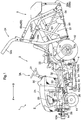
- Fig. 1 shows an overall side view of a riding type grass mower as an example of a grass mower.
- this riding type grass mower on a front side of a machine body frame 10 of a traveling machine body 1, there are provided a pair of right and left steerable front wheels 11, 11 (corresponding to "traveling device”); and on a rear side thereof, there are provided a pair of right and left drivable rear wheels 12, 12 (corresponding also to “traveling device”), so that the machine can be self-propelled.
- a rear discharge type mower device 4 is suspended to be liftable up/down.
- a grass collecting device 5 (corresponding to "work implement") for accommodating grass clippings having cut by the mower device 4 (corresponding to "work implement”).
- an engine section 2 is provided at its front portion and a riding driving section 3 is provided on the rear side of the engine section 2.
- an engine 20 is mounted on the machine body frame 10 as being accommodated within an engine hood 21. Power taken from the rear side of the engine 20 is inputted via a main transmission shaft 22 to a hydrostatic stepless speed changer device 6 disposed at a rear positon thereof; and an output from the hydrostatic stepless speed changer device 6 is transmitted, through a transmission case 23 accommodating a gear transmission mechanism 23A, to rear axles 12a supported by right and left rear axle cases 24 for driving the rear wheels 12.
- a steering operation of the front wheels 11 is effected by a power steering device (not shown) operated in response to an operation of a steering wheel 31 provided at the riding driving section 3.
- a work From the front side of the engine 20, power for a work (work implement) can be taken off. More particularly, on the front side of the engine 20, there is provided a PTO (power takeoff) mechanism 25 constituted of a belt transmission mechanism and via a PTO shaft 26 included in the PTO mechanism 25, power of the engine 20 is transmitted to the mower device 4.
- a PTO (power takeoff) mechanism 25 constituted of a belt transmission mechanism and via a PTO shaft 26 included in the PTO mechanism 25, power of the engine 20 is transmitted to the mower device 4.
- a control panel 30 disposed continuously with a rear side of the engine hood 21, and a maneuvering section 3A including the steering wheel 31, etc.
- a driver's seat 33 upwardly of an access step 32 disposed at the foot portion; and at a rear portion of this driver's seat 33, a rollover protection structure (ROPS) 34 is mounted vertically.
- ROPS rollover protection structure
- the ROPS 34 has a portal shape as seen in a front view thereof; and to a pair of right and left ROPS bases (not shown) provided integrally at rear end portions of the machine body frame 10, there are connected and fixed lower sides of pillar-like leg portions 34a, 34a disposed on the right and left opposed sides. Upper end sides of the right and left pillar-like leg portions 34a, 34a are interconnected via a portal-shaped upper frame 34b, thus covering the upper side of the driver's seat 33.
- a guard frame 10A acting as a protective member for the machine body front portion.
- the guard frame 10A is provided with a balance weight attaching portion 14 to which a plurality of balance weights can be attached.
- the mower device 4 includes a housing 40 which is suspended from the machine body frame 10 to be liftable up/down via a link mechanism 13 having pairs of front links 13a and rear links 13b on the right and left opposed sides.
- a mower lift cylinder 43 is connected in the link mechanism 13, to upper end portions of the front links 13a. In association with an expanding/contracting operation of the mower lift cylinder 43, a vertical height position of the housing 40 relative to the machine body frame 10 can be changed.
- a pair of right and left rotary blades 41, 41 Inside the housing 40, there are mounted a pair of right and left rotary blades 41, 41.
- the respective rotary blades 41 are driven to rotate at an equal speed about vertical axes with rotational paths thereof being partially overlapped with each other, whereby grass or the like will be cut, and under a conveying wind generated in association with the rotational motion, cut grass clippings may be discharged to the rear side via a discharge opening (not shown) formed at a rear portion of the housing 40.
- the grass collecting device 5 includes a grass collecting container 50 for accommodating cut grass clippings, and a lift drive mechanism 51 for allowing lifting up/down operations of the grass collecting container 50 relative to the traveling machine body 1, as well as grass discharging operation thereof.
- the grass collecting container 50 has, on its front end side, a receiving opening (not shown) for receiving cut grass clippings fed from the mower device 4 side via a conveying duct 42; and on its rear end side, a discharging opening 50a for discharging and an opening/closing lid 50b for covering this discharging opening 50a.
- the grass collecting container 50 includes: a lift link 52 which connects the grass collecting container 50 to the ROPS 34 provided on the rear side of the traveling machine body 1; lift cylinders 53 for lifting up/down the lift link 52 relative to the ROPS 34; and dump cylinders 54 for changing the posture of the grass collecting container 50 from a nearly horizontal collecting posture to a rearwardly downward rear inclined posture so as to open/close the opening/closing lid 50b of the grass collecting container 50.
- the lift link 52 includes a pair of right and left upper links 52a and a pair of right and left lower links 52b, with front end sides of the respective upper links 52b and lower links 52b being detachably connected to upper portions of the ROPS 34, and with rear sides thereof being connected to lower portions adjacent the rear end of the grass collecting container 50.
- Upper end portions of the lift cylinders 53 constituted of hydraulic cylinders are connected to the lower links 52b, so that in response to an expanding/contracting movement of the lift cylinders 53, the lift link 52 is pivoted to elevate or lower the grass collecting container 50.
- the dump cylinders 54 constituted of hydraulic cylinders are disposed downwardly of the rear end side of the grass collecting container 50.
- One end portions of the dump cylinders 54 are connected to a well-known dump operation mechanism (not shown), so that in response to an expanding/contacting movement of the dump cylinders 54, the grass collecting container 50 can be selectively operated into a discharging posture in which the grass collecting container 50 is turned over to be inclined rearwards, and a collecting posture in which the grass collecting container 50 is disposed nearly horizontal.
- the above-described lift cylinders 53, and the dump cylinders 54 as well, are one-paired right and left, respectively; and the cylinders 53, 54 are included in a hydraulic circuit for the grass collecting device 5 to be simultaneously operable on the right and left sides.
- the power transmission system from the engine 20 to the rear wheels 12 is configured as follows.
- a clutch housing 27 is provided continuously at the rear portion of the engine 20; and power of the engine 20 is taken off via an output shaft 27a of the clutch housing 27.
- the main transmission shaft 22 is connected to the rear end portion of the output shaft 27a of the clutch housing 27 to be rotatable therewith; and to the rear end portion of the main transmission shaft 22, there is connected a pump shaft 60a acting as an input shaft of the hydrostatic stepless speed changer device 6.
- the main transmission shaft 22 and the pump shaft 60a are interconnected via a connector tool 28 having a cooling fan 28a.
- the cooling fan 28a is provided for feeding cooling air to the hydrostatic stepless speed changer device 6.
- a motor shaft 61a, acting as an output shaft of the hydrostatic stepless speed changer device 6, is inserted into the transmission case 23 accommodating the gear transmission mechanism 23A, so that a speed-changed power is transmitted into the transmission case 23.
- the power transmitted from the hydrostatic stepless speed changer device 6 is transmitted in distribution to the right and left rear axle cases 24 via a differential mechanism 23B accommodated inside the transmission case 23, and then transmitted to the rear axles 12a supported by the right and left rear axle cases 24, whereby the rear wheels 12 are driven.
- the hydrostatic stepless speed changer device 6 includes: an axial plunger type and variable displacement type hydraulic motor 60 having the pump shaft 60a; an axial plunger type and variable displacement type hydraulic motor 61 having the motor shaft 61a; and a closed circuit 62 interconnecting the hydraulic pump 60 and the hydraulic motor 61 (see Fig. 4 ).
- the closed circuit 62 interconnecting the hydraulic pump 60 and the hydraulic motor 61 includes a high-pressure side oil passage 62H for feeding pressure oil from the hydraulic pump 61 to the hydraulic motor 61, and a low-pressure side oil passage 62L for returning the pressure oil from the hydraulic motor 61 to the hydraulic pump 60.
- a charge circuit 63 for replenishing an amount of pressure oil to the closed circuit 62 is connected to/between the high-pressure side oil passage 62H and the low-pressure side oil passage 62L.
- the hydraulic pump 60 is driven by power of the engine 20 together with a pressure oil feeding pump 15.
- An angle change of a swash plate 60b of the hydraulic pump 60 is done by an operator who controls a speed changer pedal 35 (see Fig. 4 ) disposed at the foot of the riding driving section 3. More particularly, the swash plate 60b of the hydraulic pump 60 is operably coupled to the speed changer pedal 35 via a hydraulic servo mechanism 7.
- the hydraulic servo mechanism 7, as shown in Fig. 4 includes: a servo valve 70 operably coupled to the speed changer pedal 35; and a servo cylinder 71 operably coupled to the swash plate 60b, so that in response to a stepping-on operation on the speed changer pedal 35, an operational oil passage 72 to the servo cylinder 71 can be switched over.
- a servo valve 70 operably coupled to the speed changer pedal 35
- a servo cylinder 71 operably coupled to the swash plate 60b, so that in response to a stepping-on operation on the speed changer pedal 35, an operational oil passage 72 to the servo cylinder 71 can be switched over.
- the servo valve 70 feeds the pressure oil from the pressure oil feeding pump 15 to the servo cylinder 71 via the operational oil passage 72.
- the servo cylinder 71 is driven to change the swash plate angle of the hydraulic pump 60, whereby the driving speed of the hydraulic pump 60 is changed correspondingly, thus changing a speed state of the hydraulic stepless speed changer device 6 correspondingly as well.
- the operation of the servo cylinder 71 is fed back to the servo valve 70 via a feedback mechanism 73.
- the pressure oil feeding pump 15 is connected via a pressure oil feeding circuit 16 to the charge circuit 63 for replenishing an amount of pressure oil to the closed circuit 62, thus effecting replenishment of the pressure oil.
- the operational oil passage 72 of the hydraulic servo mechanism 7 is also connected, thus allowing feeding of pressure oil to the servo cylinder 71. For this reason, the system pressure of the hydraulic servo mechanism 7 is set equal to the charge pressure.
- the swash plate 61b of the hydraulic motor 61 is operated by a hydraulic actuator 64 in form of a hydraulic piston.
- the hydraulic actuator 64 comprises a combination of an operational piston 64a and a return spring 64b (corresponding to "operational mechanism" for urging the swash plate 61b to be returned to a high speed side); and the operational piston 64a and the return spring 64b sandwich the swash plate 61b from the front and rear sides thereof.
- the hydraulic actuator 62 is shown with reference marks of the operational piston 64a and the return spring 64b being disposed in opposition to each other within a single cylinder. In actuality, however, as shown in Fig. 3 , the operational piston 64a and the return spring 64b are disposed on the opposed sides across the swash plate 61b to sandwich it therebetween.
- the above-described hydraulic actuator 64 is connected via an operational circuit 65 to the high-pressure side oil passage 62H of the closed circuit 62 for feeding pressure oil from the hydraulic pump 60 to the hydraulic motor 61.
- the closed circuit 62 connects the hydraulic pump 60 to the hydraulic motor 61; and the operational circuit 65 is connected to the high-pressure side oil passage 62H of the closed circuit 62 for supplying a pilot pressure taken off (branched from) the high-pressure side oil passage 62H to the hydraulic actuator 64.
- the operational circuit 65 is connected to a low-speed operation side of the hydraulic actuator 64 so as to operate the swash plate 61b of the hydraulic motor 61 to a lower speed side in association with a pressure increase in the high-pressure side oil passage 62H.
- the operational piston 64a of the hydraulic actuator 64 receives the pressure from the high-pressure side oil passage 62H via the operational circuit 65.
- the operational piston 64a is exposed to the resistance force of the initial spring force of the return spring 64b to maintain the angle of the swash plate 61b of the hydraulic motor 61 at a relatively small angle close to the neutral (0 degree), so that the grass mower will travel at a relatively high speed corresponding to the discharge amount of the hydraulic pump 60.
- the traveling load increases to exceed the set range
- the discharge amount from the hydraulic motor 61 will be increased to raise the output torque, whereby the motor shaft 61a will be driven at a reduced speed and the traveling speed of the machine body will be reduced correspondingly.
- the speed changer pedal 35 for operating the hydrostatic stepless speed changer device 6 also functions as an accelerator pedal for operating a governor (not shown) provided at a rear portion of the engine 20.
- a plurality of hydraulic motors 61 can be employed.
- some of the plurality of hydraulic motors 61 can be configured as the fixed displacement type and the others can be configured as the variable displacement type, for changing the swash plate angle.
- all of the hydraulic motors 61 can be configured as the variable displacement type for changing the angle of the swash plate 61b.
Landscapes
- Life Sciences & Earth Sciences (AREA)
- Environmental Sciences (AREA)
- Harvester Elements (AREA)
- Control Of Fluid Gearings (AREA)
Abstract
Description
- The present invention relates to a grass mower having a mower device, a traveling device and a hydrostatic stepless speed changer device. The invention is applicable to a variety of grass mowers from large sized type to small sized type.
- In a grass mower disclosed in
JP 2010-004748 A - With the above-described grass mower, since the hydrostatic stepless speed changer device is employed in its traveling driving system, smooth increase/decrease of the traveling speed is possible, but there remains room for improvement in following respects.
- Namely, with this type of grass mower, its machine body per se is not so large, but the mower is sometimes used for a grass cutting work on a sloped land, or sometimes equipped with a grass collector having a large capacity. For these reasons, during a cutting work, the mower tends to require a relatively large torque even at a low speed. Further, a traveling state without involving a cutting work is generally used for traveling on a flat land and discharging stored cut grass for instance, so that traveling should be effected at a high speed as possible for the sake of work efficiency.
- If speed increase/decrease of the traveling device is to be effected by an operation of the hydrostatic stepless speed changer device alone, in order to obtain sufficient speed increase/decrease range, a hydraulic pump having a significantly large discharge capacity will be needed as the hydrostatic speed changer device, thus inviting enlargement of the device.
- Then, it is conceivable to avoid enlargement of the hydrostatic stepless speed changer device by inputting the power outputted from the hydraulic pump to e.g. a gear type auxiliary speed changer mechanism, aside from speed change by the hydrostatic stepless speed changer device, for effecting a speed change operation by such auxiliary speed changer mechanism. In this case, however, when the auxiliary speed change operation is to be carried out, such operation as temporarily stopping the machine body for effecting the speed change operation will be needed, so that it is difficult to carry out a work in an efficient manner.
- An object of the present invention is to realize high efficiency grass cutting work by allowing speed increase/decrease of a traveling device to be effected at a speed and power output suitable for the grass cutting work, while avoiding enlargement of the hydrostatic stepless speed changer device.
- In view of the above, a grass mower as follows is proposed:
- a grass mower comprising:
- a traveling machine body having a traveling device;
- a mower device supported by the traveling machine body; and
- a hydrostatic stepless speed changer device for effecting a speed change of the traveling device, the speed changer device including:
- a hydraulic pump,
- a variable displacement type hydraulic motor, and
- a hydraulic actuator for changing a swash plate angle of the hydraulic motor;
- wherein there is provided a closed circuit which interconnects the hydraulic pump and the hydraulic motor; and an operational circuit is connected to a high-pressure side oil passage of the closed circuit for supplying a pilot pressure taken off the high-pressure side oil passage to the hydraulic actuator; and
- wherein the operational circuit is connected to a low-speed operation side of the hydraulic actuator so as to operate a swash plate of the hydraulic motor to a lower speed side in association with a pressure increase in the high-pressure side oil passage.
- With this arrangement, the hydraulic motor is configured as a variable displacement type and to a high-pressure side oil passage of a closed circuit connecting a hydraulic pump to the hydraulic motor, there is connected an operational circuit for supplying a pilot pressure taken off the high-pressure side oil passage to a hydraulic actuator for changing a swash plate angle of the hydraulic motor.
- The pilot pressure is supplied to a low-speed operational side of the hydraulic actuator so as to operate the swash plate of the hydraulic motor to its speed-reducing side, in association with a pressure increase in the high-pressure side oil passage, namely, in association with a rise in the traveling load. Whereby, the traveling speed of the machine body is operated to a speed decreasing side, but the output torque from the hydraulic motor is increased. As a result, at a place where a high-torque work is needed such as a grass cutting work on a sloped land, the traveling speed may be reduced to a lower speed, for allowing the grass cutting work to proceed in a reliable manner.
- On the other hand, in case there is no pressure rise in the high-pressure side oil passage, namely, in case the traveling load is low, the supplying of the pilot pressure to the lower speed operational side of the hydraulic actuator is cancelled or released, whereby the hydraulic actuator is returned to a high-speed operational side, and the traveling speed of the machine body will be operated to a high speed side in accordance with an operational amount of the hydraulic motor. Therefore, on a flat land traveling or the like which provides low traveling load, such work as transporting cut grass to a discharging location by high speed traveling can be readily carried out in an efficient manner.
- In this way, with speed change of the hydraulic motor according increase/decrease in the traveling load, selection between a low speed traveling placing priority over output torque or a high speed traveling placing priority on traveling speed over output torque can be made speedily via an increasing/decreasing operation on the hydraulic stepless speed changer device. Therefore, even with a hydrostatic stepless speed changer device having a relatively small speed increasing/decreasing range on the hydraulic pump side, a high-torque low-speed traveling suitable for a grass cutting work on a sloped land or the like and a low-torque high-speed traveling suitable for a grass cutting work on a flat land can be selectively provided. Thus, grass cutting works can be carried out in an efficient manner with avoiding enlargement of the hydrostatic stepless speed changer device.
- In the above-described arrangement, preferably, the hydraulic pump is of a variable displacement type, too, in addition to the hydraulic motor.
- According to one preferred embodiment, the hydraulic actuator includes an operational mechanism for urging the swash plate of the hydraulic motor to be returned to a high speed side.
- With this arrangement, since the hydraulic actuator per se includes an operational mechanism for urging the swash plate of the hydraulic motor to be returned to a high speed side, there is no need to provide the hydraulic actuator with a pilot oil passage dedicated to return operation separately from the pilot oil passage for speed reducing operation, or to provide such additional component as a pressure sensor, an electric controller or the like. Thus, the arrangement can be further simpler.
- In the above arrangement, more preferably, the operational mechanism includes a spring; and the hydraulic actuator is arranged such that an operational piston and the spring are disposed on opposite sides across the swash plate.
- Further and other features and advantages thereof will become apparent upon reading the following description.
-
-
Fig. 1 is an overall side view showing a riding type grass mower according to one embodiment, -
Fig. 2 is a schematic explanatory view showing a power transmission arrangement in a traveling driving system of the riding type grass mower, -
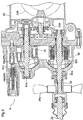
Fig. 3 is a section view showing a hydrostatic stepless speed changer device, and -
Fig. 4 is a hydraulic circuit diagram showing an operational system of the hydrostatic stepless speed changer device. - Next, one embodiment will be described.
- Unless indicated explicitly otherwise, it is understood that the forward traveling direction of a grass mower at time of a work traveling (see arrow F in
Fig. 1 ) represents the "front", the reverse traveling direction represents the "rear" and the right side represents the "right" and the left side represents the "left" relative to a forward oriented posture in the front/rear direction, respectively. -
Fig. 1 shows an overall side view of a riding type grass mower as an example of a grass mower. In this riding type grass mower, on a front side of amachine body frame 10 of a traveling machine body 1, there are provided a pair of right and left steerablefront wheels 11, 11 (corresponding to "traveling device"); and on a rear side thereof, there are provided a pair of right and left drivablerear wheels 12, 12 (corresponding also to "traveling device"), so that the machine can be self-propelled. - Beneath the
machine body frame 10 and between thefront wheels 11 and therear wheels 12 in the front/rear direction, a rear dischargetype mower device 4 is suspended to be liftable up/down. On a rear side of this traveling machine body 1, there is provided a grass collecting device 5 (corresponding to "work implement") for accommodating grass clippings having cut by the mower device 4 (corresponding to "work implement"). - As shown in
Fig. 1 andFig. 2 , on themachine body frame 10 of the traveling machine body 1, anengine section 2 is provided at its front portion and ariding driving section 3 is provided on the rear side of theengine section 2. - At the
engine section 2, anengine 20 is mounted on themachine body frame 10 as being accommodated within anengine hood 21. Power taken from the rear side of theengine 20 is inputted via amain transmission shaft 22 to a hydrostatic steplessspeed changer device 6 disposed at a rear positon thereof; and an output from the hydrostatic steplessspeed changer device 6 is transmitted, through atransmission case 23 accommodating agear transmission mechanism 23A, torear axles 12a supported by right and leftrear axle cases 24 for driving therear wheels 12. - A steering operation of the
front wheels 11 is effected by a power steering device (not shown) operated in response to an operation of asteering wheel 31 provided at theriding driving section 3. - From the front side of the
engine 20, power for a work (work implement) can be taken off. More particularly, on the front side of theengine 20, there is provided a PTO (power takeoff)mechanism 25 constituted of a belt transmission mechanism and via aPTO shaft 26 included in thePTO mechanism 25, power of theengine 20 is transmitted to themower device 4. - At the
riding driving section 3 on the rear side of theengine section 2, there are provided acontrol panel 30 disposed continuously with a rear side of theengine hood 21, and amaneuvering section 3A including thesteering wheel 31, etc. On the rear side of themaneuvering section 3A, there is provided a driver'sseat 33 upwardly of anaccess step 32 disposed at the foot portion; and at a rear portion of this driver'sseat 33, a rollover protection structure (ROPS) 34 is mounted vertically. - The
ROPS 34 has a portal shape as seen in a front view thereof; and to a pair of right and left ROPS bases (not shown) provided integrally at rear end portions of themachine body frame 10, there are connected and fixed lower sides of pillar-like leg portions like leg portions upper frame 34b, thus covering the upper side of the driver'sseat 33. - At the front portion of the
machine body frame 10, there is provided aguard frame 10A acting as a protective member for the machine body front portion. - The
guard frame 10A is provided with a balanceweight attaching portion 14 to which a plurality of balance weights can be attached. - The
mower device 4 includes ahousing 40 which is suspended from themachine body frame 10 to be liftable up/down via alink mechanism 13 having pairs offront links 13a andrear links 13b on the right and left opposed sides. - In the
link mechanism 13, to upper end portions of thefront links 13a, amower lift cylinder 43 is connected. In association with an expanding/contracting operation of themower lift cylinder 43, a vertical height position of thehousing 40 relative to themachine body frame 10 can be changed. - Inside the
housing 40, there are mounted a pair of right and leftrotary blades respective rotary blades 41 are driven to rotate at an equal speed about vertical axes with rotational paths thereof being partially overlapped with each other, whereby grass or the like will be cut, and under a conveying wind generated in association with the rotational motion, cut grass clippings may be discharged to the rear side via a discharge opening (not shown) formed at a rear portion of thehousing 40. - As shown in
Fig. 1 andFig. 2 , thegrass collecting device 5 includes agrass collecting container 50 for accommodating cut grass clippings, and alift drive mechanism 51 for allowing lifting up/down operations of thegrass collecting container 50 relative to the traveling machine body 1, as well as grass discharging operation thereof. - The
grass collecting container 50 has, on its front end side, a receiving opening (not shown) for receiving cut grass clippings fed from themower device 4 side via a conveyingduct 42; and on its rear end side, a dischargingopening 50a for discharging and an opening/closing lid 50b for covering this dischargingopening 50a. - The
grass collecting container 50 includes: alift link 52 which connects thegrass collecting container 50 to theROPS 34 provided on the rear side of the traveling machine body 1; liftcylinders 53 for lifting up/down thelift link 52 relative to theROPS 34; and dumpcylinders 54 for changing the posture of thegrass collecting container 50 from a nearly horizontal collecting posture to a rearwardly downward rear inclined posture so as to open/close the opening/closing lid 50b of thegrass collecting container 50. - The
lift link 52 includes a pair of right and leftupper links 52a and a pair of right and leftlower links 52b, with front end sides of the respectiveupper links 52b andlower links 52b being detachably connected to upper portions of theROPS 34, and with rear sides thereof being connected to lower portions adjacent the rear end of thegrass collecting container 50. Upper end portions of thelift cylinders 53 constituted of hydraulic cylinders are connected to thelower links 52b, so that in response to an expanding/contracting movement of thelift cylinders 53, thelift link 52 is pivoted to elevate or lower thegrass collecting container 50. - The
dump cylinders 54 constituted of hydraulic cylinders are disposed downwardly of the rear end side of thegrass collecting container 50. One end portions of thedump cylinders 54 are connected to a well-known dump operation mechanism (not shown), so that in response to an expanding/contacting movement of thedump cylinders 54, thegrass collecting container 50 can be selectively operated into a discharging posture in which thegrass collecting container 50 is turned over to be inclined rearwards, and a collecting posture in which thegrass collecting container 50 is disposed nearly horizontal. - The above-described
lift cylinders 53, and thedump cylinders 54 as well, are one-paired right and left, respectively; and thecylinders grass collecting device 5 to be simultaneously operable on the right and left sides. - The power transmission system from the
engine 20 to therear wheels 12 is configured as follows. - As shown in
Fig. 1 andFig. 2 , aclutch housing 27 is provided continuously at the rear portion of theengine 20; and power of theengine 20 is taken off via anoutput shaft 27a of theclutch housing 27. Themain transmission shaft 22 is connected to the rear end portion of theoutput shaft 27a of theclutch housing 27 to be rotatable therewith; and to the rear end portion of themain transmission shaft 22, there is connected apump shaft 60a acting as an input shaft of the hydrostatic steplessspeed changer device 6. - The
main transmission shaft 22 and thepump shaft 60a are interconnected via aconnector tool 28 having a coolingfan 28a. The coolingfan 28a is provided for feeding cooling air to the hydrostatic steplessspeed changer device 6. - A
motor shaft 61a, acting as an output shaft of the hydrostatic steplessspeed changer device 6, is inserted into thetransmission case 23 accommodating thegear transmission mechanism 23A, so that a speed-changed power is transmitted into thetransmission case 23. The power transmitted from the hydrostatic steplessspeed changer device 6 is transmitted in distribution to the right and leftrear axle cases 24 via adifferential mechanism 23B accommodated inside thetransmission case 23, and then transmitted to therear axles 12a supported by the right and leftrear axle cases 24, whereby therear wheels 12 are driven. - Next, the hydrostatic stepless
speed changer device 6 provided in the traveling driving system and its hydraulic driving circuit will be described. - As shown in
Fig. 3 andFig. 4 , the hydrostatic steplessspeed changer device 6 includes: an axial plunger type and variable displacement typehydraulic motor 60 having thepump shaft 60a; an axial plunger type and variable displacement typehydraulic motor 61 having themotor shaft 61a; and aclosed circuit 62 interconnecting thehydraulic pump 60 and the hydraulic motor 61 (seeFig. 4 ). - The
closed circuit 62 interconnecting thehydraulic pump 60 and thehydraulic motor 61 includes a high-pressureside oil passage 62H for feeding pressure oil from thehydraulic pump 61 to thehydraulic motor 61, and a low-pressureside oil passage 62L for returning the pressure oil from thehydraulic motor 61 to thehydraulic pump 60. Acharge circuit 63 for replenishing an amount of pressure oil to theclosed circuit 62 is connected to/between the high-pressureside oil passage 62H and the low-pressureside oil passage 62L. - The
hydraulic pump 60 is driven by power of theengine 20 together with a pressureoil feeding pump 15. An angle change of aswash plate 60b of thehydraulic pump 60 is done by an operator who controls a speed changer pedal 35 (seeFig. 4 ) disposed at the foot of theriding driving section 3. More particularly, theswash plate 60b of thehydraulic pump 60 is operably coupled to thespeed changer pedal 35 via ahydraulic servo mechanism 7. - The
hydraulic servo mechanism 7, as shown inFig. 4 , includes: aservo valve 70 operably coupled to thespeed changer pedal 35; and a servo cylinder 71 operably coupled to theswash plate 60b, so that in response to a stepping-on operation on thespeed changer pedal 35, anoperational oil passage 72 to the servo cylinder 71 can be switched over. With this arrangement, in response to release of the stepping-on operation on thespeed changer pedal 35, as shown inFig. 3 , theswash plate 60b of thehydraulic pump 60 is returned to and maintained at its neutral (0 degree), so that no discharge of pressure oil from thehydraulic pump 60 occurs, thus realizing a traveling stopped state. - As the
speed changer pedal 35 is stepped on progressively, theservo valve 70 feeds the pressure oil from the pressureoil feeding pump 15 to the servo cylinder 71 via theoperational oil passage 72. In response thereto, the servo cylinder 71 is driven to change the swash plate angle of thehydraulic pump 60, whereby the driving speed of thehydraulic pump 60 is changed correspondingly, thus changing a speed state of the hydraulic steplessspeed changer device 6 correspondingly as well. In the course thereof, the operation of the servo cylinder 71 is fed back to theservo valve 70 via a feedback mechanism 73. Thus, when the hydraulic steplessspeed changer device 6 becomes a control target speed state corresponding to the operated position of thespeed changer pedal 35, theservo valve 70 will be switched to the neutral state and the hydrostatic steplessspeed changer device 6 will be maintained at this control target speed state. - The pressure
oil feeding pump 15 is connected via a pressureoil feeding circuit 16 to thecharge circuit 63 for replenishing an amount of pressure oil to theclosed circuit 62, thus effecting replenishment of the pressure oil. To this pressureoil feeding circuit 16, theoperational oil passage 72 of thehydraulic servo mechanism 7 is also connected, thus allowing feeding of pressure oil to the servo cylinder 71. For this reason, the system pressure of thehydraulic servo mechanism 7 is set equal to the charge pressure. - The
swash plate 61b of thehydraulic motor 61 is operated by ahydraulic actuator 64 in form of a hydraulic piston. As shown inFig. 3 , Thehydraulic actuator 64 comprises a combination of anoperational piston 64a and areturn spring 64b (corresponding to "operational mechanism" for urging theswash plate 61b to be returned to a high speed side); and theoperational piston 64a and thereturn spring 64b sandwich theswash plate 61b from the front and rear sides thereof. Incidentally, in the hydraulic circuit diagram shown inFig. 4 , thehydraulic actuator 62 is shown with reference marks of theoperational piston 64a and thereturn spring 64b being disposed in opposition to each other within a single cylinder. In actuality, however, as shown inFig. 3 , theoperational piston 64a and thereturn spring 64b are disposed on the opposed sides across theswash plate 61b to sandwich it therebetween. - In operation, when the
operational piston 64a of thehydraulic actuator 64 is retracted to the front side movement limit thereof, the angle of theswash plate 61b of thehydraulic motor 61 becomes the neutral (0 degree). As theoperational piston 64a advances rearwards against the force of thereturn spring 64b, the angle of theswash pate 61b is increased progressively in correspondence therewith. Incidentally, thereturn spring 64b is assembled with an initial compression thereof, thus urging theswash plate 61b toward the neutral side with a set urging force. - As shown in
Fig. 4 , the above-describedhydraulic actuator 64 is connected via anoperational circuit 65 to the high-pressureside oil passage 62H of the closedcircuit 62 for feeding pressure oil from thehydraulic pump 60 to thehydraulic motor 61. - More particularly, the
closed circuit 62 connects thehydraulic pump 60 to thehydraulic motor 61; and theoperational circuit 65 is connected to the high-pressureside oil passage 62H of the closedcircuit 62 for supplying a pilot pressure taken off (branched from) the high-pressureside oil passage 62H to thehydraulic actuator 64. Theoperational circuit 65 is connected to a low-speed operation side of thehydraulic actuator 64 so as to operate theswash plate 61b of thehydraulic motor 61 to a lower speed side in association with a pressure increase in the high-pressureside oil passage 62H. - With this arrangement, the angle of the
swash plate 61b will be stabilized at a point where the pressure of theoperational circuit 65 and the spring force of thereturn spring 64b are balanced with each other. - In operation, therefore, when the
speed changer pedal 35 is stepped on, the angle of theswash plate 60b of thehydraulic pump 60 is increased also, so that an amount of pressure oil corresponding to the swash plate angle will be discharged to be fed to thehydraulic motor 61. - In the above, if the traveling load is relatively low and the pressure of the high-pressure
side oil passage 62H is relative low, theoperational piston 64a of thehydraulic actuator 64 receives the pressure from the high-pressureside oil passage 62H via theoperational circuit 65. Whereby, theoperational piston 64a is exposed to the resistance force of the initial spring force of thereturn spring 64b to maintain the angle of theswash plate 61b of thehydraulic motor 61 at a relatively small angle close to the neutral (0 degree), so that the grass mower will travel at a relatively high speed corresponding to the discharge amount of thehydraulic pump 60. - On the other hand, when the traveling load increases and the pressure of the high-pressure
side oil passage 62H exceeds the set range of the initial force of thereturn spring 64, theoperational piston 64a of thehydraulic actuator 64 exposed to the resistance force of the initial spring force of thereturn spring 64b will be operated toward increasing the angle of theswash plate 61b of thehydraulic motor 61 against the force of thereturn spring 64b. - Namely, when the traveling load increases to exceed the set range, the discharge amount from the
hydraulic motor 61 will be increased to raise the output torque, whereby themotor shaft 61a will be driven at a reduced speed and the traveling speed of the machine body will be reduced correspondingly. - Incidentally, the
speed changer pedal 35 for operating the hydrostatic steplessspeed changer device 6 also functions as an accelerator pedal for operating a governor (not shown) provided at a rear portion of theengine 20. - Therefore, when the
speed changer pedal 35 is stepped on, the rotational speed of the engine is increased and also the swash plate angle of thehydraulic pump 60 in the hydrostatic steplessspeed changer device 6 is operated to the speed increasing side. - The following other embodiments can be employed in any combination as desired.
- [1] In the foregoing embodiment, there was disclosed the arrangement that change of the swash plate angle of the hydrostatic stepless
speed changer device 6 is effected in operational coupling with a stepping-on operation on thespeed changer pedal 35. The invention is not limited thereto. Instead, for instance, it is also possible to arrange such that change of the swash plate angle of the hydrostatic steplessspeed changer device 6 is effected by an operation of a dedicated operational lever or the like. - [2] In the foregoing embodiment, there was disclosed the arrangement that the change of the swash plate angle of the hydrostatic stepless speed changer device is effected via the
hydraulic servo mechanism 7. The invention is not limited thereto. Instead, such ahydraulic servo mechanism 7 may be omitted so that the change can be directly made by thespeed changer pedal 35, an operational lever or the like. - [3] In the foregoing embodiment, the angle of the
swash plate 61b of thehydraulic motor 61 is changed by theoperational piston 64a and thereturn spring 64b of thehydraulic actuator 64. The invention is not limited thereto. Instead, it is also possible to change the angle of theswash plate 61b hydraulically, with using an actuator which is operated hydraulically on both the speed increasing side and the speed decreasing side. - [4] In the foregoing embodiment, the angle of the
swash plate 61b is changed by a singlehydraulic motor 61. The invention is not limited thereto. - Alternatively thereto, for instance, a plurality of
hydraulic motors 61 can be employed. In this case, some of the plurality ofhydraulic motors 61 can be configured as the fixed displacement type and the others can be configured as the variable displacement type, for changing the swash plate angle. Further alternatively, all of thehydraulic motors 61 can be configured as the variable displacement type for changing the angle of theswash plate 61b.
Claims (4)
- A grass mower comprising:a traveling machine body (1) having a traveling device (11, 12);a mower device (4) supported by the traveling machine body (1); anda hydrostatic stepless speed changer device (6) for effecting a speed change of the traveling device (11, 12), the speed changer device (6) including:wherein there is provided a closed circuit (62) which interconnects the hydraulic pump (60) and the hydraulic motor (61); and an operational circuit (65) is connected to a high-pressure side oil passage (62H) of the closed circuit (62) for supplying a pilot pressure taken off the high-pressure side oil passage (62H) to the hydraulic actuator (64); anda hydraulic pump (60),a variable displacement type hydraulic motor (61), anda hydraulic actuator (64) for changing a swash plate angle of the hydraulic motor (61);
wherein the operational circuit (65) is connected to a low-speed operation side of the hydraulic actuator (64) so as to operate a swash plate (61b) of the hydraulic motor (61) to a lower speed side in association with a pressure increase in the high-pressure side oil passage (62H). - The grass mower of claim 1, wherein the hydraulic pump (60) is of a variable displacement type.
- The grass mower of claim 1, wherein the hydraulic actuator (64) includes an operational mechanism (64b) for urging the swash plate (61b) of the hydraulic motor (61) to be returned to a high speed side.
- The grass mower of claim 3, wherein:the operational mechanism (64b) includes a spring (64b); andthe hydraulic actuator (64) is arranged such that an operational piston (64a) and the spring (64b) are disposed on opposite sides across the swash plate (61b).
Applications Claiming Priority (1)
| Application Number | Priority Date | Filing Date | Title |
|---|---|---|---|
| JP2017253513A JP6899764B2 (en) | 2017-12-28 | 2017-12-28 | Mower |
Publications (2)
| Publication Number | Publication Date |
|---|---|
| EP3504955A1 true EP3504955A1 (en) | 2019-07-03 |
| EP3504955B1 EP3504955B1 (en) | 2021-06-30 |
Family
ID=63857817
Family Applications (1)
| Application Number | Title | Priority Date | Filing Date |
|---|---|---|---|
| EP18200396.2A Active EP3504955B1 (en) | 2017-12-28 | 2018-10-15 | Grass mower |
Country Status (2)
| Country | Link |
|---|---|
| EP (1) | EP3504955B1 (en) |
| JP (1) | JP6899764B2 (en) |
Cited By (1)
| Publication number | Priority date | Publication date | Assignee | Title |
|---|---|---|---|---|
| CN115885713A (en) * | 2022-11-10 | 2023-04-04 | 温州荣仙绿化园艺工程有限公司 | A kind of urban garden intelligent maintenance equipment |
Citations (5)
| Publication number | Priority date | Publication date | Assignee | Title |
|---|---|---|---|---|
| EP2130709A1 (en) * | 2008-06-06 | 2009-12-09 | Kanzaki Kokyukoki Mfg. Co., Ltd. | vehicle transaxle system |
| EP2143315A1 (en) * | 2007-05-01 | 2010-01-13 | Yanmar Co., Ltd. | Lawn mower |
| JP2010004748A (en) | 2008-06-24 | 2010-01-14 | Kubota Corp | Mowing machine |
| US20130298546A1 (en) * | 2012-05-11 | 2013-11-14 | Kubota Corporation | Work Vehicle |
| JP2014119108A (en) * | 2012-12-19 | 2014-06-30 | Kubota Corp | Work vehicle |
Family Cites Families (8)
| Publication number | Priority date | Publication date | Assignee | Title |
|---|---|---|---|---|
| FR2843719B1 (en) * | 2002-08-23 | 2005-05-27 | Indust Design | AUTOMOTIVE WORKING VEHICLE WITH ADVANCE SPEED CONTROL ACCORDING TO THE POWER OR PRESSURE USED BY A HYDRAULICALLY DRIVEN TOOL |
| JP4101083B2 (en) * | 2003-02-25 | 2008-06-11 | 株式会社クボタ | Travel shift control device for work vehicle |
| JP4208774B2 (en) * | 2004-06-24 | 2009-01-14 | 株式会社クボタ | Riding mower |
| JP4704938B2 (en) * | 2006-03-13 | 2011-06-22 | 株式会社クボタ | Work vehicle |
| JP5108598B2 (en) * | 2008-04-10 | 2012-12-26 | 株式会社クボタ | Work vehicle |
| JP5101440B2 (en) * | 2008-08-28 | 2012-12-19 | 株式会社クボタ | Work vehicle |
| JP5215086B2 (en) * | 2008-08-28 | 2013-06-19 | 株式会社クボタ | Work vehicle |
| JP5153707B2 (en) * | 2009-03-27 | 2013-02-27 | カヤバ工業株式会社 | Hydraulic traveling work vehicle |
-
2017
- 2017-12-28 JP JP2017253513A patent/JP6899764B2/en active Active
-
2018
- 2018-10-15 EP EP18200396.2A patent/EP3504955B1/en active Active
Patent Citations (5)
| Publication number | Priority date | Publication date | Assignee | Title |
|---|---|---|---|---|
| EP2143315A1 (en) * | 2007-05-01 | 2010-01-13 | Yanmar Co., Ltd. | Lawn mower |
| EP2130709A1 (en) * | 2008-06-06 | 2009-12-09 | Kanzaki Kokyukoki Mfg. Co., Ltd. | vehicle transaxle system |
| JP2010004748A (en) | 2008-06-24 | 2010-01-14 | Kubota Corp | Mowing machine |
| US20130298546A1 (en) * | 2012-05-11 | 2013-11-14 | Kubota Corporation | Work Vehicle |
| JP2014119108A (en) * | 2012-12-19 | 2014-06-30 | Kubota Corp | Work vehicle |
Cited By (1)
| Publication number | Priority date | Publication date | Assignee | Title |
|---|---|---|---|---|
| CN115885713A (en) * | 2022-11-10 | 2023-04-04 | 温州荣仙绿化园艺工程有限公司 | A kind of urban garden intelligent maintenance equipment |
Also Published As
| Publication number | Publication date |
|---|---|
| EP3504955B1 (en) | 2021-06-30 |
| JP6899764B2 (en) | 2021-07-07 |
| JP2019118277A (en) | 2019-07-22 |
Similar Documents
| Publication | Publication Date | Title |
|---|---|---|
| US9458842B2 (en) | Closed loop drive circuit with external brake assist | |
| JP5822761B2 (en) | Combine drive transmission | |
| EP2652212B1 (en) | Closed loop drive circuit with open circuit pump assist for high speed travel | |
| EP3738424A1 (en) | Grass mowing machine | |
| US12311769B2 (en) | Work vehicle | |
| EP3504955B1 (en) | Grass mower | |
| US20120061158A1 (en) | Working vehicle | |
| JP5745227B2 (en) | Shifting operation structure of work vehicle | |
| EP3305626A1 (en) | Work vehicle | |
| EP4431766A2 (en) | Working vehicle | |
| US7172040B2 (en) | Riding type mower | |
| US20030079452A1 (en) | Tractor | |
| JP5852708B2 (en) | Combine | |
| EP3504952B1 (en) | Work vehicle | |
| JP3513421B2 (en) | Mower | |
| US12402550B2 (en) | Work machine | |
| US20260126104A1 (en) | Hydraulic systems for a power machine | |
| JP3760842B2 (en) | Hydraulic equipment for powered vehicles | |
| JP6671194B2 (en) | Work vehicle | |
| JP2021004586A (en) | Work vehicle | |
| JP3497408B2 (en) | Paddy working machine | |
| JP5612384B2 (en) | Combine | |
| JP3671934B2 (en) | Hydraulic equipment for powered vehicles | |
| JPH1156013A (en) | Hydraulic circuits such as tractors | |
| JPH06113604A (en) | Hydraulic system of power vehicle |
Legal Events
| Date | Code | Title | Description |
|---|---|---|---|
| PUAI | Public reference made under article 153(3) epc to a published international application that has entered the european phase |
Free format text: ORIGINAL CODE: 0009012 |
|
| STAA | Information on the status of an ep patent application or granted ep patent |
Free format text: STATUS: REQUEST FOR EXAMINATION WAS MADE |
|
| 17P | Request for examination filed |
Effective date: 20181015 |
|
| AK | Designated contracting states |
Kind code of ref document: A1 Designated state(s): AL AT BE BG CH CY CZ DE DK EE ES FI FR GB GR HR HU IE IS IT LI LT LU LV MC MK MT NL NO PL PT RO RS SE SI SK SM TR |
|
| AX | Request for extension of the european patent |
Extension state: BA ME |
|
| REG | Reference to a national code |
Ref country code: DE Ref legal event code: R079 Ref document number: 602018019266 Country of ref document: DE Free format text: PREVIOUS MAIN CLASS: A01D0034690000 Ipc: A01D0069030000 |
|
| RIC1 | Information provided on ipc code assigned before grant |
Ipc: A01D 34/64 20060101ALN20201222BHEP Ipc: A01D 69/03 20060101AFI20201222BHEP Ipc: A01D 34/69 20060101ALI20201222BHEP |
|
| GRAP | Despatch of communication of intention to grant a patent |
Free format text: ORIGINAL CODE: EPIDOSNIGR1 |
|
| STAA | Information on the status of an ep patent application or granted ep patent |
Free format text: STATUS: GRANT OF PATENT IS INTENDED |
|
| RIC1 | Information provided on ipc code assigned before grant |
Ipc: A01D 34/64 20060101ALN20210125BHEP Ipc: A01D 34/69 20060101ALI20210125BHEP Ipc: A01D 69/03 20060101AFI20210125BHEP |
|
| INTG | Intention to grant announced |
Effective date: 20210210 |
|
| GRAS | Grant fee paid |
Free format text: ORIGINAL CODE: EPIDOSNIGR3 |
|
| GRAA | (expected) grant |
Free format text: ORIGINAL CODE: 0009210 |
|
| STAA | Information on the status of an ep patent application or granted ep patent |
Free format text: STATUS: THE PATENT HAS BEEN GRANTED |
|
| AK | Designated contracting states |
Kind code of ref document: B1 Designated state(s): AL AT BE BG CH CY CZ DE DK EE ES FI FR GB GR HR HU IE IS IT LI LT LU LV MC MK MT NL NO PL PT RO RS SE SI SK SM TR |
|
| REG | Reference to a national code |
Ref country code: CH Ref legal event code: EP |
|
| REG | Reference to a national code |
Ref country code: AT Ref legal event code: REF Ref document number: 1405461 Country of ref document: AT Kind code of ref document: T Effective date: 20210715 |
|
| REG | Reference to a national code |
Ref country code: DE Ref legal event code: R096 Ref document number: 602018019266 Country of ref document: DE |
|
| REG | Reference to a national code |
Ref country code: IE Ref legal event code: FG4D |
|
| REG | Reference to a national code |
Ref country code: LT Ref legal event code: MG9D |
|
| PG25 | Lapsed in a contracting state [announced via postgrant information from national office to epo] |
Ref country code: BG Free format text: LAPSE BECAUSE OF FAILURE TO SUBMIT A TRANSLATION OF THE DESCRIPTION OR TO PAY THE FEE WITHIN THE PRESCRIBED TIME-LIMIT Effective date: 20210930 Ref country code: FI Free format text: LAPSE BECAUSE OF FAILURE TO SUBMIT A TRANSLATION OF THE DESCRIPTION OR TO PAY THE FEE WITHIN THE PRESCRIBED TIME-LIMIT Effective date: 20210630 Ref country code: HR Free format text: LAPSE BECAUSE OF FAILURE TO SUBMIT A TRANSLATION OF THE DESCRIPTION OR TO PAY THE FEE WITHIN THE PRESCRIBED TIME-LIMIT Effective date: 20210630 |
|
| REG | Reference to a national code |
Ref country code: NL Ref legal event code: MP Effective date: 20210630 |
|
| REG | Reference to a national code |
Ref country code: AT Ref legal event code: MK05 Ref document number: 1405461 Country of ref document: AT Kind code of ref document: T Effective date: 20210630 |
|
| PG25 | Lapsed in a contracting state [announced via postgrant information from national office to epo] |
Ref country code: GR Free format text: LAPSE BECAUSE OF FAILURE TO SUBMIT A TRANSLATION OF THE DESCRIPTION OR TO PAY THE FEE WITHIN THE PRESCRIBED TIME-LIMIT Effective date: 20211001 Ref country code: NO Free format text: LAPSE BECAUSE OF FAILURE TO SUBMIT A TRANSLATION OF THE DESCRIPTION OR TO PAY THE FEE WITHIN THE PRESCRIBED TIME-LIMIT Effective date: 20210930 Ref country code: LV Free format text: LAPSE BECAUSE OF FAILURE TO SUBMIT A TRANSLATION OF THE DESCRIPTION OR TO PAY THE FEE WITHIN THE PRESCRIBED TIME-LIMIT Effective date: 20210630 Ref country code: SE Free format text: LAPSE BECAUSE OF FAILURE TO SUBMIT A TRANSLATION OF THE DESCRIPTION OR TO PAY THE FEE WITHIN THE PRESCRIBED TIME-LIMIT Effective date: 20210630 Ref country code: RS Free format text: LAPSE BECAUSE OF FAILURE TO SUBMIT A TRANSLATION OF THE DESCRIPTION OR TO PAY THE FEE WITHIN THE PRESCRIBED TIME-LIMIT Effective date: 20210630 |
|
| PG25 | Lapsed in a contracting state [announced via postgrant information from national office to epo] |
Ref country code: RO Free format text: LAPSE BECAUSE OF FAILURE TO SUBMIT A TRANSLATION OF THE DESCRIPTION OR TO PAY THE FEE WITHIN THE PRESCRIBED TIME-LIMIT Effective date: 20210630 Ref country code: NL Free format text: LAPSE BECAUSE OF FAILURE TO SUBMIT A TRANSLATION OF THE DESCRIPTION OR TO PAY THE FEE WITHIN THE PRESCRIBED TIME-LIMIT Effective date: 20210630 Ref country code: PT Free format text: LAPSE BECAUSE OF FAILURE TO SUBMIT A TRANSLATION OF THE DESCRIPTION OR TO PAY THE FEE WITHIN THE PRESCRIBED TIME-LIMIT Effective date: 20211102 Ref country code: CZ Free format text: LAPSE BECAUSE OF FAILURE TO SUBMIT A TRANSLATION OF THE DESCRIPTION OR TO PAY THE FEE WITHIN THE PRESCRIBED TIME-LIMIT Effective date: 20210630 Ref country code: AT Free format text: LAPSE BECAUSE OF FAILURE TO SUBMIT A TRANSLATION OF THE DESCRIPTION OR TO PAY THE FEE WITHIN THE PRESCRIBED TIME-LIMIT Effective date: 20210630 Ref country code: SK Free format text: LAPSE BECAUSE OF FAILURE TO SUBMIT A TRANSLATION OF THE DESCRIPTION OR TO PAY THE FEE WITHIN THE PRESCRIBED TIME-LIMIT Effective date: 20210630 Ref country code: SM Free format text: LAPSE BECAUSE OF FAILURE TO SUBMIT A TRANSLATION OF THE DESCRIPTION OR TO PAY THE FEE WITHIN THE PRESCRIBED TIME-LIMIT Effective date: 20210630 Ref country code: EE Free format text: LAPSE BECAUSE OF FAILURE TO SUBMIT A TRANSLATION OF THE DESCRIPTION OR TO PAY THE FEE WITHIN THE PRESCRIBED TIME-LIMIT Effective date: 20210630 Ref country code: ES Free format text: LAPSE BECAUSE OF FAILURE TO SUBMIT A TRANSLATION OF THE DESCRIPTION OR TO PAY THE FEE WITHIN THE PRESCRIBED TIME-LIMIT Effective date: 20210630 |
|
| PG25 | Lapsed in a contracting state [announced via postgrant information from national office to epo] |
Ref country code: PL Free format text: LAPSE BECAUSE OF FAILURE TO SUBMIT A TRANSLATION OF THE DESCRIPTION OR TO PAY THE FEE WITHIN THE PRESCRIBED TIME-LIMIT Effective date: 20210630 |
|
| REG | Reference to a national code |
Ref country code: DE Ref legal event code: R097 Ref document number: 602018019266 Country of ref document: DE |
|
| PG25 | Lapsed in a contracting state [announced via postgrant information from national office to epo] |
Ref country code: DK Free format text: LAPSE BECAUSE OF FAILURE TO SUBMIT A TRANSLATION OF THE DESCRIPTION OR TO PAY THE FEE WITHIN THE PRESCRIBED TIME-LIMIT Effective date: 20210630 |
|
| REG | Reference to a national code |
Ref country code: DE Ref legal event code: R119 Ref document number: 602018019266 Country of ref document: DE |
|
| PLBE | No opposition filed within time limit |
Free format text: ORIGINAL CODE: 0009261 |
|
| STAA | Information on the status of an ep patent application or granted ep patent |
Free format text: STATUS: NO OPPOSITION FILED WITHIN TIME LIMIT |
|
| REG | Reference to a national code |
Ref country code: CH Ref legal event code: PL |
|
| PG25 | Lapsed in a contracting state [announced via postgrant information from national office to epo] |
Ref country code: AL Free format text: LAPSE BECAUSE OF FAILURE TO SUBMIT A TRANSLATION OF THE DESCRIPTION OR TO PAY THE FEE WITHIN THE PRESCRIBED TIME-LIMIT Effective date: 20210630 |
|
| 26N | No opposition filed |
Effective date: 20220331 |
|
| REG | Reference to a national code |
Ref country code: BE Ref legal event code: MM Effective date: 20211031 |
|
| PG25 | Lapsed in a contracting state [announced via postgrant information from national office to epo] |
Ref country code: MC Free format text: LAPSE BECAUSE OF FAILURE TO SUBMIT A TRANSLATION OF THE DESCRIPTION OR TO PAY THE FEE WITHIN THE PRESCRIBED TIME-LIMIT Effective date: 20210630 |
|
| PG25 | Lapsed in a contracting state [announced via postgrant information from national office to epo] |
Ref country code: LU Free format text: LAPSE BECAUSE OF NON-PAYMENT OF DUE FEES Effective date: 20211015 Ref country code: IT Free format text: LAPSE BECAUSE OF FAILURE TO SUBMIT A TRANSLATION OF THE DESCRIPTION OR TO PAY THE FEE WITHIN THE PRESCRIBED TIME-LIMIT Effective date: 20210630 Ref country code: DE Free format text: LAPSE BECAUSE OF NON-PAYMENT OF DUE FEES Effective date: 20220503 Ref country code: BE Free format text: LAPSE BECAUSE OF NON-PAYMENT OF DUE FEES Effective date: 20211031 |
|
| PG25 | Lapsed in a contracting state [announced via postgrant information from national office to epo] |
Ref country code: LI Free format text: LAPSE BECAUSE OF NON-PAYMENT OF DUE FEES Effective date: 20211031 Ref country code: CH Free format text: LAPSE BECAUSE OF NON-PAYMENT OF DUE FEES Effective date: 20211031 |
|
| PG25 | Lapsed in a contracting state [announced via postgrant information from national office to epo] |
Ref country code: IE Free format text: LAPSE BECAUSE OF NON-PAYMENT OF DUE FEES Effective date: 20211015 |
|
| PG25 | Lapsed in a contracting state [announced via postgrant information from national office to epo] |
Ref country code: LT Free format text: LAPSE BECAUSE OF FAILURE TO SUBMIT A TRANSLATION OF THE DESCRIPTION OR TO PAY THE FEE WITHIN THE PRESCRIBED TIME-LIMIT Effective date: 20210630 |
|
| GBPC | Gb: european patent ceased through non-payment of renewal fee |
Effective date: 20221015 |
|
| PG25 | Lapsed in a contracting state [announced via postgrant information from national office to epo] |
Ref country code: CY Free format text: LAPSE BECAUSE OF FAILURE TO SUBMIT A TRANSLATION OF THE DESCRIPTION OR TO PAY THE FEE WITHIN THE PRESCRIBED TIME-LIMIT Effective date: 20210630 |
|
| PG25 | Lapsed in a contracting state [announced via postgrant information from national office to epo] |
Ref country code: HU Free format text: LAPSE BECAUSE OF FAILURE TO SUBMIT A TRANSLATION OF THE DESCRIPTION OR TO PAY THE FEE WITHIN THE PRESCRIBED TIME-LIMIT; INVALID AB INITIO Effective date: 20181015 |
|
| PG25 | Lapsed in a contracting state [announced via postgrant information from national office to epo] |
Ref country code: GB Free format text: LAPSE BECAUSE OF NON-PAYMENT OF DUE FEES Effective date: 20221015 |
|
| PG25 | Lapsed in a contracting state [announced via postgrant information from national office to epo] |
Ref country code: MK Free format text: LAPSE BECAUSE OF FAILURE TO SUBMIT A TRANSLATION OF THE DESCRIPTION OR TO PAY THE FEE WITHIN THE PRESCRIBED TIME-LIMIT Effective date: 20210630 |
|
| PG25 | Lapsed in a contracting state [announced via postgrant information from national office to epo] |
Ref country code: MT Free format text: LAPSE BECAUSE OF FAILURE TO SUBMIT A TRANSLATION OF THE DESCRIPTION OR TO PAY THE FEE WITHIN THE PRESCRIBED TIME-LIMIT Effective date: 20210630 |
|
| PGFP | Annual fee paid to national office [announced via postgrant information from national office to epo] |
Ref country code: FR Payment date: 20250908 Year of fee payment: 8 |
|
| PG25 | Lapsed in a contracting state [announced via postgrant information from national office to epo] |
Ref country code: TR Free format text: LAPSE BECAUSE OF FAILURE TO SUBMIT A TRANSLATION OF THE DESCRIPTION OR TO PAY THE FEE WITHIN THE PRESCRIBED TIME-LIMIT Effective date: 20210630 |