EP3504743B1 - Battery system - Google Patents
Battery system Download PDFInfo
- Publication number
- EP3504743B1 EP3504743B1 EP17842488.3A EP17842488A EP3504743B1 EP 3504743 B1 EP3504743 B1 EP 3504743B1 EP 17842488 A EP17842488 A EP 17842488A EP 3504743 B1 EP3504743 B1 EP 3504743B1
- Authority
- EP
- European Patent Office
- Prior art keywords
- module
- backplane
- battery
- power connector
- controller
- Prior art date
- Legal status (The legal status is an assumption and is not a legal conclusion. Google has not performed a legal analysis and makes no representation as to the accuracy of the status listed.)
- Active
Links
Images




Classifications
-
- H—ELECTRICITY
- H01—ELECTRIC ELEMENTS
- H01M—PROCESSES OR MEANS, e.g. BATTERIES, FOR THE DIRECT CONVERSION OF CHEMICAL ENERGY INTO ELECTRICAL ENERGY
- H01M10/00—Secondary cells; Manufacture thereof
- H01M10/42—Methods or arrangements for servicing or maintenance of secondary cells or secondary half-cells
- H01M10/425—Structural combination with electronic components, e.g. electronic circuits integrated to the outside of the casing
-
- H—ELECTRICITY
- H01—ELECTRIC ELEMENTS
- H01M—PROCESSES OR MEANS, e.g. BATTERIES, FOR THE DIRECT CONVERSION OF CHEMICAL ENERGY INTO ELECTRICAL ENERGY
- H01M10/00—Secondary cells; Manufacture thereof
- H01M10/42—Methods or arrangements for servicing or maintenance of secondary cells or secondary half-cells
- H01M10/48—Accumulators combined with arrangements for measuring, testing or indicating the condition of cells, e.g. the level or density of the electrolyte
- H01M10/482—Accumulators combined with arrangements for measuring, testing or indicating the condition of cells, e.g. the level or density of the electrolyte for several batteries or cells simultaneously or sequentially
-
- H—ELECTRICITY
- H01—ELECTRIC ELEMENTS
- H01M—PROCESSES OR MEANS, e.g. BATTERIES, FOR THE DIRECT CONVERSION OF CHEMICAL ENERGY INTO ELECTRICAL ENERGY
- H01M10/00—Secondary cells; Manufacture thereof
- H01M10/42—Methods or arrangements for servicing or maintenance of secondary cells or secondary half-cells
- H01M10/48—Accumulators combined with arrangements for measuring, testing or indicating the condition of cells, e.g. the level or density of the electrolyte
- H01M10/486—Accumulators combined with arrangements for measuring, testing or indicating the condition of cells, e.g. the level or density of the electrolyte for measuring temperature
-
- H—ELECTRICITY
- H01—ELECTRIC ELEMENTS
- H01M—PROCESSES OR MEANS, e.g. BATTERIES, FOR THE DIRECT CONVERSION OF CHEMICAL ENERGY INTO ELECTRICAL ENERGY
- H01M50/00—Constructional details or processes of manufacture of the non-active parts of electrochemical cells other than fuel cells, e.g. hybrid cells
- H01M50/20—Mountings; Secondary casings or frames; Racks, modules or packs; Suspension devices; Shock absorbers; Transport or carrying devices; Holders
- H01M50/204—Racks, modules or packs for multiple batteries or multiple cells
- H01M50/207—Racks, modules or packs for multiple batteries or multiple cells characterised by their shape
- H01M50/209—Racks, modules or packs for multiple batteries or multiple cells characterised by their shape adapted for prismatic or rectangular cells
-
- H—ELECTRICITY
- H01—ELECTRIC ELEMENTS
- H01M—PROCESSES OR MEANS, e.g. BATTERIES, FOR THE DIRECT CONVERSION OF CHEMICAL ENERGY INTO ELECTRICAL ENERGY
- H01M50/00—Constructional details or processes of manufacture of the non-active parts of electrochemical cells other than fuel cells, e.g. hybrid cells
- H01M50/20—Mountings; Secondary casings or frames; Racks, modules or packs; Suspension devices; Shock absorbers; Transport or carrying devices; Holders
- H01M50/244—Secondary casings; Racks; Suspension devices; Carrying devices; Holders characterised by their mounting method
-
- H—ELECTRICITY
- H01—ELECTRIC ELEMENTS
- H01M—PROCESSES OR MEANS, e.g. BATTERIES, FOR THE DIRECT CONVERSION OF CHEMICAL ENERGY INTO ELECTRICAL ENERGY
- H01M50/00—Constructional details or processes of manufacture of the non-active parts of electrochemical cells other than fuel cells, e.g. hybrid cells
- H01M50/20—Mountings; Secondary casings or frames; Racks, modules or packs; Suspension devices; Shock absorbers; Transport or carrying devices; Holders
- H01M50/284—Mountings; Secondary casings or frames; Racks, modules or packs; Suspension devices; Shock absorbers; Transport or carrying devices; Holders with incorporated circuit boards, e.g. printed circuit boards [PCB]
-
- H—ELECTRICITY
- H01—ELECTRIC ELEMENTS
- H01M—PROCESSES OR MEANS, e.g. BATTERIES, FOR THE DIRECT CONVERSION OF CHEMICAL ENERGY INTO ELECTRICAL ENERGY
- H01M50/00—Constructional details or processes of manufacture of the non-active parts of electrochemical cells other than fuel cells, e.g. hybrid cells
- H01M50/50—Current conducting connections for cells or batteries
- H01M50/502—Interconnectors for connecting terminals of adjacent batteries; Interconnectors for connecting cells outside a battery casing
- H01M50/507—Interconnectors for connecting terminals of adjacent batteries; Interconnectors for connecting cells outside a battery casing comprising an arrangement of two or more busbars within a container structure, e.g. busbar modules
-
- H—ELECTRICITY
- H01—ELECTRIC ELEMENTS
- H01M—PROCESSES OR MEANS, e.g. BATTERIES, FOR THE DIRECT CONVERSION OF CHEMICAL ENERGY INTO ELECTRICAL ENERGY
- H01M50/00—Constructional details or processes of manufacture of the non-active parts of electrochemical cells other than fuel cells, e.g. hybrid cells
- H01M50/50—Current conducting connections for cells or batteries
- H01M50/502—Interconnectors for connecting terminals of adjacent batteries; Interconnectors for connecting cells outside a battery casing
- H01M50/509—Interconnectors for connecting terminals of adjacent batteries; Interconnectors for connecting cells outside a battery casing characterised by the type of connection, e.g. mixed connections
- H01M50/51—Connection only in series
-
- H—ELECTRICITY
- H01—ELECTRIC ELEMENTS
- H01M—PROCESSES OR MEANS, e.g. BATTERIES, FOR THE DIRECT CONVERSION OF CHEMICAL ENERGY INTO ELECTRICAL ENERGY
- H01M50/00—Constructional details or processes of manufacture of the non-active parts of electrochemical cells other than fuel cells, e.g. hybrid cells
- H01M50/50—Current conducting connections for cells or batteries
- H01M50/502—Interconnectors for connecting terminals of adjacent batteries; Interconnectors for connecting cells outside a battery casing
- H01M50/519—Interconnectors for connecting terminals of adjacent batteries; Interconnectors for connecting cells outside a battery casing comprising printed circuit boards [PCB]
-
- H—ELECTRICITY
- H01—ELECTRIC ELEMENTS
- H01M—PROCESSES OR MEANS, e.g. BATTERIES, FOR THE DIRECT CONVERSION OF CHEMICAL ENERGY INTO ELECTRICAL ENERGY
- H01M50/00—Constructional details or processes of manufacture of the non-active parts of electrochemical cells other than fuel cells, e.g. hybrid cells
- H01M50/50—Current conducting connections for cells or batteries
- H01M50/572—Means for preventing undesired use or discharge
- H01M50/574—Devices or arrangements for the interruption of current
-
- H—ELECTRICITY
- H01—ELECTRIC ELEMENTS
- H01M—PROCESSES OR MEANS, e.g. BATTERIES, FOR THE DIRECT CONVERSION OF CHEMICAL ENERGY INTO ELECTRICAL ENERGY
- H01M50/00—Constructional details or processes of manufacture of the non-active parts of electrochemical cells other than fuel cells, e.g. hybrid cells
- H01M50/50—Current conducting connections for cells or batteries
- H01M50/572—Means for preventing undesired use or discharge
- H01M50/574—Devices or arrangements for the interruption of current
- H01M50/581—Devices or arrangements for the interruption of current in response to temperature
-
- H—ELECTRICITY
- H01—ELECTRIC ELEMENTS
- H01M—PROCESSES OR MEANS, e.g. BATTERIES, FOR THE DIRECT CONVERSION OF CHEMICAL ENERGY INTO ELECTRICAL ENERGY
- H01M2200/00—Safety devices for primary or secondary batteries
- H01M2200/10—Temperature sensitive devices
-
- H—ELECTRICITY
- H01—ELECTRIC ELEMENTS
- H01M—PROCESSES OR MEANS, e.g. BATTERIES, FOR THE DIRECT CONVERSION OF CHEMICAL ENERGY INTO ELECTRICAL ENERGY
- H01M50/00—Constructional details or processes of manufacture of the non-active parts of electrochemical cells other than fuel cells, e.g. hybrid cells
- H01M50/50—Current conducting connections for cells or batteries
- H01M50/543—Terminals
- H01M50/547—Terminals characterised by the disposition of the terminals on the cells
- H01M50/55—Terminals characterised by the disposition of the terminals on the cells on the same side of the cell
-
- Y—GENERAL TAGGING OF NEW TECHNOLOGICAL DEVELOPMENTS; GENERAL TAGGING OF CROSS-SECTIONAL TECHNOLOGIES SPANNING OVER SEVERAL SECTIONS OF THE IPC; TECHNICAL SUBJECTS COVERED BY FORMER USPC CROSS-REFERENCE ART COLLECTIONS [XRACs] AND DIGESTS
- Y02—TECHNOLOGIES OR APPLICATIONS FOR MITIGATION OR ADAPTATION AGAINST CLIMATE CHANGE
- Y02E—REDUCTION OF GREENHOUSE GAS [GHG] EMISSIONS, RELATED TO ENERGY GENERATION, TRANSMISSION OR DISTRIBUTION
- Y02E60/00—Enabling technologies; Technologies with a potential or indirect contribution to GHG emissions mitigation
- Y02E60/10—Energy storage using batteries
Definitions
- the present disclosure relates to a battery system as typically used in the maritime industry. More particularly the disclosure relates to a battery system comprising one or more battery modules and a backplane, to a module power connector for a battery module, and to a backplane power connector for a backplane.
- One type of rechargeable battery is a lithium-ion battery, comprising a number of serially connected cells.
- the battery is typically housed in an enclosure to form a battery module.
- electrical energy is converted to and stored as chemical energy during charging, and stored chemical energy is converted to electrical energy during discharging.
- US 2016/093843 discloses for example already battery modules connected to a common backplane.
- Battery modules typically include positive and negative connectors on their front face, to which power cable assemblies are connected to form a string of modules terminating at a switchgear (or pack controller).
- Coolant inlet and outlet connections are typically also provided on the front face of the battery module.
- External flexible hoses connect these coolant fittings to external rigid pipes mounted on the front surfaces of the rack system.
- Such connections are often difficult and labour-intensive to install and service, are subject to poor manufacturing quality due to crimping issues, and still further are easy to miss-wire by the installer/servicer, which can lead to a short circuit.
- cables are often exposed on the front face of the rack they are subject to impact / mechanical damage from other equipment or activity. With the cabling exposed on the front face of the modules, battery packs are also at a risk of coolant leaks where coolant can spill onto the floor in the immediate area of the battery room leading to unsafe conditions.
- connection / disassembly of all of the individual interfaces mentioned above is generally required until the module is free to be installed/removed from the rack.
- the main power connectors are sometimes subject to overheating. It is common practice in the industry to regularly inspect the high voltage connectors to determine if they are overheating. This is typically done visually, for example by imaging the connectors using a commercially available infrared camera. This can be a time-consuming procedure, and it would be advantageous if improved, alternative methods of inspecting high voltage connectors were available.
- a battery system comprising a backplane for engaging with one or more battery modules as defined in claim 1.
- Each battery module may comprise more than one module power connector.
- Each module power connector and/or each backplane power connector may comprise one or more of the temperature-sensitive electronic components.
- the backplane may be coupled to a racking structure defining one or more battery bays, and moving the battery module into engagement with the backplane may comprise sliding the battery module into a battery bay until it engages with the backplane.
- a temperature-sensitive electronic component may comprise any component capable of measuring temperature, such as a temperature sensor, or may comprise a component which may be used to indirectly measure temperature.
- the component may have a measurable property which changes as a function of temperature, and the measurable property may be monitored in order to derive temperature.
- monitoring of the temperature of the power connectors may be carried out without the need to rely on infrared cameras or the like, by instead using temperature-sensitive electronic components disposed within thermally conductive distance of the module power connector and/or the backplane power connector. This may be particularly useful when a blind mate engagement is used, as described below, which can lead to the module and backplane power connectors being inaccessible when engaged to one another.
- the module power connector may be configured to engage with the corresponding backplane power connector in a blind mate engagement.
- a blind mate engagement may be achieved by sliding a battery module into operational engagement with the backplane.
- Power connections may be formed when power pins (which may be comprised in the module power connector) at the rear of the battery module engage with power sockets (which may be comprised in the backplane power connector) secured within the backplane (or, in the reverse case, power pins in the backplane may engage with sockets in the battery module).
- the power sockets may each be connected to busbars such that, when all the battery modules are engaged with the backplane, a complete series string is formed, with both ends of the string (positive and negative) terminating at a power switchgear device, which may be referred to as a pack controller.
- the interconnecting busbars may be flexible to allow for slight misalignment of the module power connector relative to the backplane power connector, when engaging the two together, therefore allowing a correct fit with minimal force necessary to seat the connectors.
- the module power connector and/or the corresponding backplane power connector may comprise one or more alignment features for guiding engagement of the module power connector with the corresponding backplane power connector such that, when moving the battery module into engagement with the backplane, the one or more alignment features may correct for at least some misalignment of the module power connector relative to the corresponding backplane power connector.
- the one or more alignment features may comprise one or more tapered portions provided on one or more of the module power connector and the backplane power connector.
- the one or more temperature-sensitive electronic components may comprise one or more thermistors.
- At least some of the one or more temperature-sensitive electronic components may be positioned on the corresponding backplane power connector.
- the module power connector and the corresponding backplane power connector may be inaccessible when the battery module is engaged with the backplane.
- Each battery module may further comprise a module communication connector configured to engage with a corresponding backplane communication connector on the backplane.
- the module communication connector may be comprised in the module power connector, or may be a separate component to the module power connector.
- the backplane communication connector may be comprised in the backplane power connector, or may be a separate component to the backplane power connector.
- the module communication connector and the corresponding backplane communication connector may comprise optical communication connectors.
- Each battery module may be configured to engage with the backplane in a blind mate engagement whereby the module communication connector is positioned within optically communicative distance of the corresponding backplane communication connector.
- optical connections may therefore be formed when optical ports in the module optical communication connector at the rear of the battery module come within sufficient proximity of optical ports in the corresponding backplane optical communication connector.
- a gap may be formed between the module communication connector and the corresponding backplane communication connector.
- the optical medium is preferably inexpensive low-bandwidth light pipe material.
- the optical interface air gap is preferably small enough able to sufficiently tolerate misalignment such that generally no high-precision components or special alignment / calibration procedures are required to ensure correct alignment of the module optical communication connector with the backplane optical communication connector.
- the pack controller may be communicative with the module controller and may be further configured to determine the safety-disconnect condition has been satisfied if the power connector temperature is determined to exceed a preset temperature threshold.
- the module controller may be further configured to open the safety-disconnect loop if: a voltage of one or more cells in the battery module is determined to exceed a preset voltage threshold, the voltage being measured by a sensor electrically coupled to the module controller; a cell temperature of one or more cells in the battery module is determined to exceed a preset cell temperature threshold, the cell temperature being measured by a sensor electrically coupled to the module controller; or an ambient temperature of the battery module is determined to exceed a preset ambient temperature threshold, the ambient temperature being measured by a sensor electrically coupled to the module controller.
- the module power connector may comprise module contacts and interlock contacts.
- the interlock contacts may be electrically coupled to the module controller and corresponding interlock contacts in the corresponding backplane power connector when the battery module is engaged with the backplane.
- the module controller may be further configured to open the safety-disconnect loop in response to the battery module being disengaged from the backplane.
- the module controller may be further configured to open the safety-disconnect loop by comparing of a reference electrical resistance electrically coupled to the module controller to an electrical resistance across the interlock contacts
- the one or more temperature-sensitive electronic components may be: comprised in the module power connector and electrically coupled to the interlock contacts; comprised in the module power connector and electrically coupled to the module contacts; or comprised in the backplane power connector and electrically coupled to the jumper.
- the backplane may further comprise a plurality of flexible busbars interconnecting adjacent backplane power connectors.
- the pack controller may be further configured to: send over the safety-disconnect loop a sleep instruction to the module controller if a required power flow to/from the battery module is determined to be below a preset power threshold; and send over the safety-disconnect loop a wake-up instruction to the module controller if a required power flow to/from the battery module is determined to be above a preset power threshold.
- the module controller may be further configured to: operate in a low-power mode in response to receiving the sleep instruction; and operate in a normal mode in response to receiving the wake-up instruction.
- a module power connector for a battery module.
- the module power connector is configured to engage with a corresponding backplane power connector on a backplane, thereby forming a path for power flow between the battery module and the backplane.
- the module power connector comprises one or more temperature-sensitive electronic components configured to detect a change in temperature of the module power connector.
- the module power connector of the present aspect of the disclosure may be the module power connector described above in connection with the first aspect of the disclosure. Accordingly, the module power connector of the present aspect of the disclosure may comprise any of the features of the module power connector described above in connection with the first aspect of the disclosure.
- a backplane power connector for a backplane.
- the backplane power connector is configured to engage with a corresponding module power connector on a battery module, thereby forming a path for power flow between the battery module and the backplane.
- the backplane power connector comprises one or more temperature-sensitive electronic components configured to detect a change in temperature of backplane power connector.
- the backplane power connector of the present aspect of the disclosure may be the backplane power connector described above in connection with the first aspect of the disclosure. Accordingly, the backplane power connector of the present aspect of the disclosure may comprise any of the features of the backplane power connector described above in connection with the first aspect of the disclosure.
- each module power connector with a corresponding backplane power connector may comprise a blind mate engagement.
- Each module power connector and/or each corresponding backplane power connector may comprise one or more alignment features for guiding engagement of the module power connector with the corresponding backplane power connector such that, when moving the battery module into engagement with the backplane, the one or more alignment features correct for at least some misalignment of the module power connector relative to the corresponding backplane power connector.
- a battery system comprising: a backplane for engaging with one or more battery modules, the backplane comprising one or more backplane optical communication connectors.
- the battery system further comprises one or more battery modules each comprising a module optical communication connector and each being configured to engage with the backplane by moving the battery module into engagement with the backplane such that the module optical communication connector engages with a corresponding backplane optical communication connector in a blind mate engagement.
- the battery system further comprises one or more optical fibres terminating at the one or more backplane optical communication connectors.
- Each module optical communication connector may comprise one or more alignment features for guiding engagement of the module optical communication connector with the corresponding backplane optical communication connector such that, when moving the battery module into engagement with the backplane, the one or more alignment features correct for at least some misalignment of the module optical communication connector relative to the corresponding backplane optical communication connector.
- Engagement of the one or more battery modules with the backplane may comprise the one or more battery modules being positioned relative to the backplane such that one or more module optical ports in each module optical communication connector are located within optically communicative distance of corresponding backplane optical ports in the corresponding backplane optical communication connector.
- a gap may be formed between the one or more module optical ports and the corresponding one or more backplane optical ports.
- Each battery module may further comprise a module power connector configured to engage with the backplane by moving the battery module into engagement with the backplane such that the module power connector engages with a corresponding backplane power connector in the backplane.
- Each battery module may further comprise one or more temperature-sensitive electronic components positioned within thermally conductive distance of, and configured to detect a change in temperature of, either, or both of, the module power connector and the corresponding backplane power connector.
- the one or more temperature-sensitive electronic components may comprise one or more thermistors.
- At least some of the one or more temperature-sensitive electronic components may be positioned on the module power connector.
- At least some of the one or more temperature-sensitive electronic components may be positioned on the corresponding backplane power connector.
- the module power connector and the corresponding backplane power connector may be inaccessible when the battery module is engaged with the backplane.
- the battery system may further comprise a power switching device for interrupting power flow between the backplane and the one or more battery modules, the battery system further comprising a pack controller configured, when a safety-disconnect condition is determined by the pack controller to be satisfied, to operate the switching device so as to interrupt power flow between the backplane and the one or more battery modules.
- Each battery module may further comprise a module controller configured to determine a power connector temperature of the module power connector and/or the backplane power connector, based on a change in temperature detected by the one or more temperature-sensitive electronic components.
- the one or more temperature-sensitive electronic components may comprise one or more thermistors.
- the module controller may be further configured to determine the power connector temperature based on an electrical resistance of the one or more thermistors. For example the power connector temperature may be determined based on a reference electrical resistance electrically coupled to the module controller, and an electrical resistance of the one or more thermistors.
- the pack controller may be communicative with the module controller and may be further configured to determine the safety-disconnect condition has been satisfied if the power connector temperature is determined to exceed a preset temperature threshold.
- the module controller may be configured to communicate with the pack controller over a safety-disconnect loop.
- the module controller may be further configured to open the safety-disconnect loop if the power connector temperature is determined to exceed the preset temperature threshold, thereby preventing the module controller from communicating with the pack controller.
- the safety disconnect condition may be satisfied when the module controller is no longer communicating with the pack controller.
- the module controller may be determined to no longer be communicating with the pack controller when the pack controller determines that the module controller has not communicated with the pack controller over the safety-disconnect loop for a predetermined amount of time.
- the safety-disconnect loop may comprise the one or more optical fibres.
- the module controller may be further configured to open the safety-disconnect loop if: a voltage of one or more cells in the battery module is determined to exceed a preset voltage threshold, the voltage being measured by a sensor electrically coupled to the module controller; a cell temperature of one or more cells in the battery module is determined to exceed a preset cell temperature threshold, the cell temperature being measured by a sensor electrically coupled to the module controller; or an ambient temperature of the battery module is determined to exceed a preset ambient temperature threshold, the ambient temperature being measured by a sensor electrically coupled to the module controller.
- the module power connector may comprise module contacts and interlock contacts.
- the interlock contacts may be electrically coupled to the module controller and corresponding interlock contacts in the corresponding backplane power connector when the battery module is engaged with the backplane.
- the module controller may be further configured to open the safety-disconnect loop in response to the battery module being disengaged from the backplane.
- the corresponding backplane power connector may comprise a jumper positioned such that, when the battery module is engaged with the backplane, the jumper is electrically coupled to the interlock contacts, and, when the battery module is disengaged from the backplane, the jumper is disconnected from the interlock contacts.
- the module controller may be further configured to open the safety-disconnect loop based on an electrical resistance across the interlock contacts. For example, the module controller may be further configured to open the safety-disconnect loop by comparing a reference electrical resistance electrically coupled to the module controller to an electrical resistance across the interlock contacts.
- the one or more temperature-sensitive electronic components are: comprised in the module power connector and electrically coupled to the interlock contacts; comprised in the module power connector and electrically coupled to the module contacts; or comprised in the corresponding backplane power connector and electrically coupled to the jumper.
- the one or more backplane power connectors may be movably coupled to the backplane.
- the backplane may further comprise a plurality of flexible busbars interconnecting adjacent backplane power connectors.
- the pack controller may be further configured to: send over the safety-disconnect loop a sleep instruction to the module controller if a required power flow to/from the battery module is determined to be below a preset power threshold; and send over the safety-disconnect loop a wake-up instruction to the module controller if a required power flow to/from the battery module is determined to be above a preset power threshold.
- the module controller may be further configured to: operate in a low-power mode in response to receiving the sleep instruction; and operate in a normal mode in response to receiving the wake-up instruction.
- Couple and variants of it such as “coupled”, “couples”, and “coupling” as used in this disclosure are intended to include indirect and direct connections unless otherwise indicated. For example, if a first article is coupled to a second article, that coupling may be through a direct connection or through an indirect connection via one or more other articles.
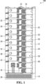
- Rack assembly 100 comprises side walls 10 and 12 joining a base 14 and a top 16.
- a dividing wall 18 extends from base 14 to top 16 and separates rack assembly 100 into a left-hand column and a right-hand column.
- Each column comprises multiple battery bays 20 for receiving battery modules.
- Each battery bay 20 is configured to receive or accept a single battery module though in other embodiments a battery bay may be configured to receive more than one battery module.
- Side walls 10, 12 and dividing wall 18 each comprise guiding members 22 for assisting proper alignment of battery modules during insertion of the battery modules into rack assembly 100.
- Base 14 houses an airflow chamber beneath battery bays 20.
- the front of base 14 is provided with a vented duct 26 to allow the passage of air.
- Rack assembly 100 further comprises a backplane 28 defining a rear wall of rack assembly 100.
- the rear wall of rack assembly 100 is said to be on a battery module-receiving side of backplane 28.
- Backplane 28 forms a rear wall of each battery bay 20 and comprises a number of backplane power connectors 32 comprising backplane optical connectors 33, arranged to engage with or mate with corresponding module power ports/connectors and module optical ports/connectors on a battery module.
- Each battery bay 20 is therefore provided with a backplane power connector 32 and a backplane optical connector 33 for engaging with a battery module inserted within the battery bay.
- Backplane power connectors 32 and backplane optical connectors 33 are movably coupled to backplane 28, such that backplane power connectors 32 and backplane optical connectors 33 may move laterally slightly in the plane defined by backplane 28.
- Flexible busbars 24 are provided to interconnect two adjacent backplane power connectors 32 such that electrical power may flow from one backplane power connector 32 to another. Because of their flexibility, during engagement of a battery module 38 with backplane 28, slight misalignment of battery module 38 will be corrected by the flexible busbars and the movable coupling of backplane power connectors 32 and backplane optical connectors 33 with backplane 28, allowing slight movement of backplane power connectors 32 relative to the battery module 38.
- the backplane power connector 32 at lower left is used to connect to a ship's DC bus.
- Backplane power connectors 32 and backplane optical connectors 33 are positioned proximate dividing wall 18.
- FIG 1 shows rack assembly 100 in an empty configuration. That is, in Figure 1 rack assembly 100 is shown without any battery modules installed.
- Battery module 38 such as that shown in Figures 3A and 3B may be used with rack assembly 100.
- Figures 3A and 3B there is shown an embodiment of a battery module 38 that may installed in rack assembly 100.
- Figure 3A shows a front view of battery module 38
- Figure 3B shows a rear view of battery module 38.
- Battery module 38 houses (though not a shown) a number of cells disposed in a stacked arrangement within an enclosure 40.
- module optical communication ports 42, module power ports 44 and exhaust seal 46 are shown on the rear face of battery module 38.
- Module optical communication ports 42 and module power ports 44 are comprised in a module power connector 200 (described in more detail below).
- Module optical communication ports 42 are positioned in a vertical alignment, as are module power ports 44. Module optical communication ports 42 and module power ports 44 form part of a module power/communication connector, described in more detail below.
- a heat sink 48 comprising a finned arrangement for assisting heat dissipation away from battery module 38.
- battery modules (such as battery module 38) are installed in a rack assembly by sliding a battery module into a vacant battery bay of the rack assembly.
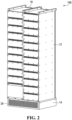
- a fully-filled rack assembly 100 is shown in Figure 2 .
- Each battery bay 20 contains a battery module 38 inserted therein, each battery module being engaged with backplane 28.
- battery module 38 is inserted rear face first into a vacant battery bay 20.
- Battery module 38 is inserted fully into battery bay 20 until reaching a mating position, wherein in the mating position module optical ports 42 and module power ports 44 (of battery module 38) blind matingly engage with corresponding ports in a backplane optical connector 33 and a backplane power connector 32 (of backplane 28), and exhaust seal 46 (of battery module 38) blind matingly engages with an exhaust port 34 (of backplane 28). Guiding members 22 assist with proper alignment of the battery module 38's ports relative to the corresponding ports on backplane 28.
- alignment features provided on the module power/communication connector also assist in alignment of the battery module 38's ports relative to the corresponding ports on backplane 28.
- engagement of module optical ports 42 with a backplane optical connector 33, engagement of module power ports 44 with a backplane power connector 32, and engagement of exhaust seal 46 with an exhaust port 34 comprises a blind mate engagement.
- a blind mate engagement may be any engagement where self-aligning features on the connectors allow for slight misalignment during coupling/engagement of one connector to another. The self-aligning features assist in proper alignment of the connectors to ensure a proper engagement of the connectors.
- Engagement of module optical ports 42 with a corresponding backplane optical connector 33 means that module optical ports 42 are brought into optically communicative proximity of corresponding ports in backplane optical connector 33.
- each battery module 38 there is no need for a user to manually connect each battery module 38 to backplane 28.
- the optical and electrical engagement of each battery module 38 with backplane 28 is assured by the proper alignment of optical/power connectors 42/44 with optical/power connectors 33/32, and the proper alignment of exhaust seal 46 and exhaust port 34, on both the rear face of battery module 38 and on backplane 28.
- module power/communication connector 200 in accordance with an embodiment of the disclosure.
- module power/communication connector 200 will be referred to simply as module power connector 200.
- Module power connector 200 is used with battery module 38 as described in connection with Figures 3A and 3B , and is disposed on the rear side of battery module 38 (i.e. the side that engages with backplane 28).
- Module power connector 200 comprises optical communication ports 42 for optical communication with corresponding ports on a backplane power connector of backplane 28, to which module power connector 200 is to be engaged.
- Module power connector 200 comprises thermistors 204 whose operation is described in more detail below.
- High Voltage Interlock Loop (HVIL) connections 206 extend from HVIL power ports 208 and, when module power connector 200 is engaged to backplane 28, to a local HVIL jumper (not shown). The operation of the HVIL is discussed in more detail below.
- Adjacent HVIL power ports 208 is a bonding/ground connection 212 connected to bonding/ground port 210.
- Adjacent HVIL and bonding/ground ports 208, 210 are battery connection pass-throughs 214 allowing the main battery module contacts to engage with corresponding contacts in the corresponding backplane power connector 32. Battery connection pass-throughs 214 form the outside of power ports 44 seen in Figure 3B .
- a blind mate interface PCB 218 is included. Blind mate interface PCB 218 provides a means of aggregating a number of signals, including those from HVIL connections 206 and thermistors 204, and directing those signals to an interface PCB connector.
- module power connector 200 The backplane-facing side of module power connector 200 is shown in Figure 4B .
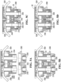
- FIGS 5A-5D there is shown module power connector 200 being brought into engagement with corresponding backplane power connector 32.
- Figure 5A shows module power connector 200 and backplane power connector 32 in an unmated position
- Figure 5B shows module power connector 200 and backplane power connector 32 in an aligned position
- Figure 5C shows module power connector 200 and backplane power connector 32 in a power mated position
- Figure 5D shows module power connector 200 and backplane power connector 32 in a fully mated position.
- Module power connector 200 includes power sockets 250, HVIL socket 252 and blind mate lead-in taper 216.
- Backplane power connector 32 includes power pins 254 for insertion into power sockets 250, and HVIL jumper pin 256 for insertion into HVIL socket 252.
- power pins 254 are self-aligned with power sockets 250 by virtue of blind mate lead-in taper 216 interacting with backplane power connector 32.
- Flexible busbars 258 coupled to backplane power connector 32 may movably flex during engagement of module power connector 200 with backplane power connector 32, thereby causing backplane power connector 32 to move relative to backplane 28 and assist with the alignment of backplane power connector 32 with module power connector 200.
- power pins 254 are shown in electrical contact with power sockets 250, and in Figure 5D module power connector 200 and backplane power connector 32 are shown fully engaged or mated, with HVIL jumper 256 electrically coupled with HVIL socket 252.
- HVIL jumper 256 disengages from HVIL socket 252 before power pins 254 disengage from power sockets 250.
- Backplane power connector 32 includes optical fibres 260 terminating at optical lenses 262.
- Module power connector 200 includes optical ports 42, as well as opto-electronic components 264 in optical communication with optical fibres 260.
- Electronic signals generated by a module controller on the battery module may be received at opto-electronic components 264, converted into optical signals and transmitted to the pack controller via optical fibres 260.
- a foam gasket 266 separates module power connector 200 from backplane power connector 32.
- the battery system of the present disclosure will now be described in use.
- a high-voltage battery system such as the one described in connection with Figures 1-6
- the module and backplane power connectors are sometimes subject to overheating.
- the connectors are generally inaccessible and visual inspection of the connectors is usually not possible.
- the present disclosure provides for a system and method of determining whether the module and/or backplane connectors are overheating, as will be described below.
- Other risks to lithium ion batteries include overcharging, over-discharging, and high temperatures in general. To protect against such hazards, it is typical to implement a number of safety-disconnect features, again as will now be described in more detail below.
- FIG. 7A is a circuit diagram of battery module 38, according to an embodiment of the disclosure.
- Battery module 38 includes a number of serially connected cells 52.
- Battery module 38 further includes a number of voltage sensors 54 connected to cells 52 and configured to read the voltage of each cell 52.
- the outputs of voltage sensors 54 are directed to comparators 56.
- the outputs of comparators 56 are connected to a logic block 58 that asserts its output if any of the outputs of comparators 56 is asserted.
- logic block 58 may comprise one or more logical OR-gates and/or logical AND-gates.
- Battery module 38 further includes a temperature sensor 60 used to measure an ambient temperature of battery module 38.
- temperature sensor 60 may be positioned so as to monitor the temperature of one or more of cells 52.
- Battery module 38 may include one or more further temperature sensors (not shown) for measuring the temperature at different locations within battery module 38.
- the output of temperature sensor 60 is directed to comparator 62, whose output in turn is fed to logic block 58.
- a thermistor 66 (for example one of thermistors 204 in Figure 4A ) is integrated within module power connector 64 (shown with dashed lines), which includes module terminals 64a and High Voltage Interlock Loop (HVIL) terminals 64b.
- Module power connector 64 may be the same as module power connector 200 described above, but for the purpose of Figures 7A-8 is labelled differently.
- thermistor 66 is electrically coupled to HVIL terminals 64b. Thermistor 66 is positioned to detect changes in temperature of module power connector 64. As known in the art, the resistance of thermistor 66 will vary with the sensed temperature of module power connector 64. Therefore, as the temperature of module power connector 64 varies, so too does the electrical resistance of thermistor 66.
- Thermistor 66 is connected to pull-down resistor 68, together forming a voltage divider circuit.
- An analog-to-digital converter (ADC) 70 measures the voltage at the voltage divider circuit. The voltage measured by ADC 70 will vary as a function of the resistance at thermistor 66, resulting in a voltage change measured by ADC 70.
- a programmable logic device 72 such as a microcontroller, is used to convert the voltage measured by ADC 70 into a temperature. The output of programmable logic device 72 is configured to communicate directly with a pack controller 81 (see Figure 7B ) over a battery management system communication link (not shown).
- the output of programmable logic device 72 may be configured to communicate with logic block 81.
- Logic block 58 is configured to control a switching device 76, such as a relay, a transistor, or an AND-gate, operable to alternately open or close a safety-disconnect loop 78.
- FIG. 7B is a circuit diagram of a number of battery modules 38 connected in series to pack controller 81 and switching device 82.
- Safety-disconnect loop 78 comprises a continuous signal path that passes through all of battery modules 38 that are connected to pack controller 81. If the switching device 76 of any battery module 38 interrupts (that is, opens) safety disconnect loop 78, then pack controller 81 is configured to open switching device 82 thereby preventing further charging or discharging of battery modules 38.
- Safety-disconnect loop 78 comprises an optical communication medium such as optical fibres (for example optical fibres 260 described above) that terminate at a module optical communication connector 80. The optical signal carried by safety-disconnect loop 78 is converted to an electronic signal at an opto-electronic receiver 90.
- opto-electronic receiver 90 passes through switching device 76 and into opto-electronic transmitter 91 that is operable to convert the electric signal into an optical signal.
- Opto-electronic receiver 90 may be, for example, a photo-transistor or a photo-diode.
- Opto-electronic transmitter 91 may be, for example, a light-emitting diode or a laser.
- the above-described components embody a number of safety-disconnect features which can be used to interrupt the flow of power to/from battery module 38 should any one of a number of safety parameters not be met.
- the voltage across the battery pack terminals 100, 101 can typically be up to 1200 Volts. With such a high voltage, it would be dangerous to disconnect battery module 38 from the battery pack while the battery string (i.e. the remaining battery modules in the pack) remains connected to the main DC bus, because bus voltage would be exposed on the backplane connectors.
- overheating of the module/backplane connectors, overcharging/over-discharging of the battery module, and high operating temperatures are all conditions under which it is unsafe to operate the battery module.
- safety-disconnect loop 78 is used to automatically disconnect the battery system from the DC bus as soon as an unsafe condition is detected.
- the output of temperature sensor 60 is compared to a preset temperature threshold in comparator 62.
- Comparator 62 will output a digital signal to logic block 58 if the measured temperature is greater than the preset temperature threshold.
- the digital signal received at logic block 58 will trigger logic block 58 to operate switching device 76, thereby opening safety-disconnect loop 78.
- Opening safety-disconnect loop 78 will cause pack controller 81 to determine a safety-disconnect condition has been met, and will result in pack controller 81 operating switching device 82 to disconnect battery module 38 from the DC bus. Thus, further overheating of battery module 38 may be prevented.
- the outputs of voltage sensors 54 are compared to preset voltage thresholds in comparators 56.
- a comparator 56 will output a digital signal to logic block 58 if the voltage measured by its respective voltage sensor 54 is greater than the preset voltage threshold.
- the digital signal received at logic block 58 will trigger logic block 58 to operate switching device 76, thereby opening safety-disconnect loop 78.
- opening safety-disconnect loop 78 will result in pack controller 81 determining that a safety-disconnect condition has been met.
- pack controller 81 will operate switching device 82 to interrupt power flow to/from battery module 50, thereby preventing further overcharging/overdischarging.
- Comparators 56 are configured so that if the voltage of a cell 52 exceeds an allowable upper threshold (for example 4.20V for lithium ion NMC cells) then their output signal is asserted. Comparators 56 may also be configured so that if the voltage of a cell 52 falls below an allowable lower threshold (for example 2.70V for lithium ion NMC cells) then their output signal is asserted.
- an allowable upper threshold for example 4.20V for lithium ion NMC cells
- Comparators 56 may also be configured so that if the voltage of a cell 52 falls below an allowable lower threshold (for example 2.70V for lithium ion NMC cells) then their output signal is asserted.
- Safety-disconnect loop 78 is also used to interrupt power flow to/from battery module 50 in the event that battery module 50 is disconnected from the backplane.
- a voltage supply 67 provides voltage to High Voltage Interlock Loop (HVIL) terminals 64b.
- HVIL terminals 64b are connected to voltage supply 67 and the voltage is returned by an HVIL jumper 65.
- Current then passes from voltage supply 67, through HVIL jumper 65 and through thermistor 66 and pull-down resistor 68.
- Thermistor 66 and pull-down resistor 68 form a voltage divider.
- the resistance value of pull-down resistor 68 is selected so that the voltage input at a comparator 74 is measurably above zero.
- HVIL terminals 64b disconnect from HVIL jumper 65 so that there is no current through the voltage divider, and pull-down resistor 68 holds the voltage at comparator 74 to be zero.
- Comparator 74 is designed so that a low voltage asserts the output to logic block 58 whereas a high voltage de-asserts the output.
- safety-disconnect loop 78 may also be opened through the use of thermistor 66.
- ADC 70 measures the voltage at the voltage divider circuit created by thermistor 66 and pull-down resistor 68.
- Programmable logic device 72 converts the voltage measured by ADC 70 into a temperature which is compared to a preset temperature threshold stored within programmable logic device 72.
- a digital output is asserted to logic block 58 if the measured temperature exceeds the preset temperature threshold.
- the temperature threshold may be set so as to ensure that the operation of module power connector 64 remains within a safe operational temperature range for the materials of which it (and other parts of the battery pack that are in thermal contact with it) is comprised.
- a module connector composed in part of plastic may have a safe operational temperature below 100 degrees C, and the preset temperature threshold may therefore be set to 90 degrees C. Any other suitable temperature threshold is contemplated within the scope of this disclosure.
- the digital signal received at logic block 58 will trigger logic block 58 to operate switching device 76, thereby opening safety-disconnect loop 78.
- opening safety-disconnect loop 78 will result in pack controller 81 determining that a safety-disconnect condition has been met.
- pack controller 81 operates switching device 82 to disconnect the string of battery modules 38 from the DC bus.
- power flow to/from battery modules 38 via module terminals 64a is prevented.
- overheating of module power connector 64 may be prevented.
- programmable logic device 72 transmits the temperature value via a battery management system communications link (not shown) directly to pack controller 81, without going via safety-disconnect loop 78.
- the communication will cause pack controller 81 to determine a safety-disconnect condition has been met, and will result in pack controller 81 operating switching device 82 to disconnect battery module 38 from the DC bus.
- pack controller 81 operating switching device 82 to disconnect battery module 38 from the DC bus.
- programmable logic device 72 may comprise software which is generally more failure-prone than hardware comprised in pack controller 81). Rather, the functionality of programmable logic device 72 may be carried out in pack controller 81.
- FIG. 8 An alternative embodiment of battery module 38 is shown in Figure 8 .
- a pair of thermistors 66a and 66b are electrically coupled to module terminals 64a, as opposed to HVIL terminals 64b.
- the operation of the circuit of Figure 8 is otherwise identical to that of Figure 7A .
- programmable device logic 72 transmits the temperature value received from either ADC 70a, 70b via a battery management system communications link (not shown) directly to pack controller 81 , without going via safety-disconnect loop 78.
- Pack controller 81 determines whether a safety-disconnect condition has been met.
- thermistor 66 may be integrated with HVIL jumper 65 comprised in the backplane power connector.
- thermistor 66 may be located on, within or otherwise within thermally conductive distance of the backplane power connector, and may be electrically coupled to HVIL jumper 65. Thermistor 66 will therefore be responsive to changes in temperature of the backplane power connector, and will result in switching device 76 being operated should the temperature of the backplane power connector increase beyond a preset threshold, as described above.
- battery module 38 of Figure 8 forms part of a series connection of multiple battery modules 38 (such as shown in Figure 7B ). Furthermore, operation of switching device 82 will result in other battery modules 38 in the series string being disconnected from the DC bus. Thus, should one battery module experience a safety-critical issue (i.e. overheating/overvoltage etc.), then all battery modules in the series string will be disconnected from the DC bus.
- a safety-critical issue i.e. overheating/overvoltage etc.
- any part of any aspect or embodiment discussed in this specification can be implemented or combined with any part of any other aspect or embodiment discussed in this specification.
- multiple thermistors in series may be used.
Landscapes
- Chemical & Material Sciences (AREA)
- Chemical Kinetics & Catalysis (AREA)
- Electrochemistry (AREA)
- General Chemical & Material Sciences (AREA)
- Engineering & Computer Science (AREA)
- Manufacturing & Machinery (AREA)
- Microelectronics & Electronic Packaging (AREA)
- Secondary Cells (AREA)
- Charge And Discharge Circuits For Batteries Or The Like (AREA)
- Protection Of Static Devices (AREA)
Description
- The present disclosure relates to a battery system as typically used in the maritime industry. More particularly the disclosure relates to a battery system comprising one or more battery modules and a backplane, to a module power connector for a battery module, and to a backplane power connector for a backplane.
- One type of rechargeable battery is a lithium-ion battery, comprising a number of serially connected cells. The battery is typically housed in an enclosure to form a battery module. During normal operating conditions, electrical energy is converted to and stored as chemical energy during charging, and stored chemical energy is converted to electrical energy during discharging.
-
US 2016/093843 discloses for example already battery modules connected to a common backplane. - There are various problems with current racks for battery modules. Battery modules typically include positive and negative connectors on their front face, to which power cable assemblies are connected to form a string of modules terminating at a switchgear (or pack controller). Coolant inlet and outlet connections are typically also provided on the front face of the battery module. External flexible hoses connect these coolant fittings to external rigid pipes mounted on the front surfaces of the rack system. Such connections are often difficult and labour-intensive to install and service, are subject to poor manufacturing quality due to crimping issues, and still further are easy to miss-wire by the installer/servicer, which can lead to a short circuit. Furthermore, as the cables are often exposed on the front face of the rack they are subject to impact / mechanical damage from other equipment or activity. With the cabling exposed on the front face of the modules, battery packs are also at a risk of coolant leaks where coolant can spill onto the floor in the immediate area of the battery room leading to unsafe conditions.
- With current battery packs, installation/servicing of a battery module is also a relatively involved process. In order to install or remove a module from the battery pack, connection / disassembly of all of the individual interfaces mentioned above is generally required until the module is free to be installed/removed from the rack.
- Still further, multiple cable lengths are often required to accommodate the various physical arrangements of the battery modules. This can result in complex and excessively long power circuits. Often the power circuit will cross over itself with the cable jackets in contact with one another, leading to potential hot spots. The overall loop area formed as a result of the cabling can be large, potentially causing electromagnetic interference (EMI) issues.
- Yet further, because of the high power output of such battery systems, the main power connectors are sometimes subject to overheating. It is common practice in the industry to regularly inspect the high voltage connectors to determine if they are overheating. This is typically done visually, for example by imaging the connectors using a commercially available infrared camera. This can be a time-consuming procedure, and it would be advantageous if improved, alternative methods of inspecting high voltage connectors were available.
- The present disclosure seeks to address these and other needs in the art.
- In a first aspect of the disclosure, there is provided a battery system comprising a backplane for engaging with one or more battery modules as defined in claim 1.
- Each battery module may comprise more than one module power connector. Each module power connector and/or each backplane power connector may comprise one or more of the temperature-sensitive electronic components. The backplane may be coupled to a racking structure defining one or more battery bays, and moving the battery module into engagement with the backplane may comprise sliding the battery module into a battery bay until it engages with the backplane. A temperature-sensitive electronic component may comprise any component capable of measuring temperature, such as a temperature sensor, or may comprise a component which may be used to indirectly measure temperature. For example, the component may have a measurable property which changes as a function of temperature, and the measurable property may be monitored in order to derive temperature.
- With the above battery system, monitoring of the temperature of the power connectors (either of the modules or of the backplane) may be carried out without the need to rely on infrared cameras or the like, by instead using temperature-sensitive electronic components disposed within thermally conductive distance of the module power connector and/or the backplane power connector. This may be particularly useful when a blind mate engagement is used, as described below, which can lead to the module and backplane power connectors being inaccessible when engaged to one another.
- The module power connector may be configured to engage with the corresponding backplane power connector in a blind mate engagement. A blind mate engagement may be achieved by sliding a battery module into operational engagement with the backplane. Power connections may be formed when power pins (which may be comprised in the module power connector) at the rear of the battery module engage with power sockets (which may be comprised in the backplane power connector) secured within the backplane (or, in the reverse case, power pins in the backplane may engage with sockets in the battery module). The power sockets may each be connected to busbars such that, when all the battery modules are engaged with the backplane, a complete series string is formed, with both ends of the string (positive and negative) terminating at a power switchgear device, which may be referred to as a pack controller. The interconnecting busbars may be flexible to allow for slight misalignment of the module power connector relative to the backplane power connector, when engaging the two together, therefore allowing a correct fit with minimal force necessary to seat the connectors.
- The module power connector and/or the corresponding backplane power connector may comprise one or more alignment features for guiding engagement of the module power connector with the corresponding backplane power connector such that, when moving the battery module into engagement with the backplane, the one or more alignment features may correct for at least some misalignment of the module power connector relative to the corresponding backplane power connector. The one or more alignment features may comprise one or more tapered portions provided on one or more of the module power connector and the backplane power connector.
- The one or more temperature-sensitive electronic components may comprise one or more thermistors.
- At least some of the one or more temperature-sensitive electronic components may be positioned on the module power connector.
- At least some of the one or more temperature-sensitive electronic components may be positioned on the corresponding backplane power connector.
- The module power connector and the corresponding backplane power connector may be inaccessible when the battery module is engaged with the backplane. In particular, in some embodiments it may not be possible, during engagement of the module and backplane power connectors, to visually locate the power connectors to assist in their alignment.
- Each battery module may further comprise a module communication connector configured to engage with a corresponding backplane communication connector on the backplane. The module communication connector may be comprised in the module power connector, or may be a separate component to the module power connector. The backplane communication connector may be comprised in the backplane power connector, or may be a separate component to the backplane power connector.
- The module communication connector and the corresponding backplane communication connector may comprise optical communication connectors. Each battery module may be configured to engage with the backplane in a blind mate engagement whereby the module communication connector is positioned within optically communicative distance of the corresponding backplane communication connector. In a battery module's operational position (i.e. when engaged with the backplane), optical connections may therefore be formed when optical ports in the module optical communication connector at the rear of the battery module come within sufficient proximity of optical ports in the corresponding backplane optical communication connector. In the operational position, a gap may be formed between the module communication connector and the corresponding backplane communication connector.
- The optical medium is preferably inexpensive low-bandwidth light pipe material. The optical interface air gap is preferably small enough able to sufficiently tolerate misalignment such that generally no high-precision components or special alignment / calibration procedures are required to ensure correct alignment of the module optical communication connector with the backplane optical communication connector.
- The module power connector and/or the corresponding backplane power connector may comprise one or more alignment features for guiding engagement of the module power connector with the corresponding backplane power connector such that, when moving the battery module into engagement with the backplane, the one or more alignment features correct for at least some misalignment of the module communication connector relative to the corresponding backplane communication connector. Thus, physically engaging the module power connectors with the backplane power connectors may be sufficient to bring the module communication connectors into communicative coupling with the backplane communication connectors. The communicative coupling may comprise a physical coupling (for example if electrical communication is being used) or alternatively may comprise a non-physical coupling, for example if optical communication is being used, as described above.
- The battery system may further comprise a power switching device for interrupting power flow between the backplane and the one or more battery modules. The battery system may further comprise a pack controller configured, when a safety-disconnect condition is determined by the pack controller to be satisfied, to operate the power switching device so as to interrupt power flow between the backplane and the one or more battery modules. The pack controller may be configured to disconnect the one or more battery modules from a DC power bus, thereby interrupting power flow between the backplane and the one or more battery modules.
- Each battery module may comprise a module controller configured to determine a power connector temperature of the module power connector and/or the corresponding backplane power connector, based on a change in temperature detected by the one or more temperature-sensitive electronic components. The module controller may comprise programmable logic such as one or more microprocessors and one or more memories cooperating together so as to carry out programmed instructions, such as software. In some embodiments, the module controller may comprise processing circuitry configured to carry out the methods described herein.
- The one or more temperature-sensitive electronic components may comprise one or more thermistors. The module controller may be further configured to determine the power connector temperature based on an electrical resistance of the one or more thermistors. For example the power connector temperature may be determined based on a comparison of a reference electrical resistance electrically coupled to the module controller, and an electrical resistance of the one or more thermistors. The reference electrical resistance may be determined by a pull-down or pull-up resistor electrically coupled to the module controller.
- The pack controller may be communicative with the module controller and may be further configured to determine the safety-disconnect condition has been satisfied if the power connector temperature is determined to exceed a preset temperature threshold.
- The module controller may be further configured to communicate with the pack controller over a safety-disconnect loop. The module controller may be further configured to open the safety-disconnect loop if the power connector temperature is determined to exceed the preset temperature threshold, thereby preventing the module controller from communicating with the pack controller. The safety disconnect condition may be satisfied when the module controller is no longer communicating with the pack controller. The module controller may be configure to operate a relay or other switch-type device, such as an optical relay, in order to open/close the safety-disconnect loop.
- The module controller may determine to no longer be communicating with the pack controller when the pack controller determines that the module controller has not communicated with the pack controller over the safety-disconnect loop for a predetermined amount of time.
- The safety-disconnect loop may comprise an optical communication medium. The optical communication medium may comprise an optical fibre terminating at the backplane communication connector. Optical signals sent from the module controller to the pack controller may be transmitted through an air interface gap between the module communication connector and the backplane communication connector, via the one or more optical fibres, and may be detected by an optical receiver in the backplane communication connector, or in some other part of the backplane.
- The module controller may be further configured to open the safety-disconnect loop if: a voltage of one or more cells in the battery module is determined to exceed a preset voltage threshold, the voltage being measured by a sensor electrically coupled to the module controller; a cell temperature of one or more cells in the battery module is determined to exceed a preset cell temperature threshold, the cell temperature being measured by a sensor electrically coupled to the module controller; or an ambient temperature of the battery module is determined to exceed a preset ambient temperature threshold, the ambient temperature being measured by a sensor electrically coupled to the module controller.
- The module power connector may comprise module contacts and interlock contacts. The interlock contacts may be electrically coupled to the module controller and corresponding interlock contacts in the corresponding backplane power connector when the battery module is engaged with the backplane. The module controller may be further configured to open the safety-disconnect loop in response to the battery module being disengaged from the backplane.
- The backplane power connector may comprise a jumper positioned such that, when the battery module is engaged with the backplane, the jumper is electrically coupled to the interlock contacts, and, when the battery module is disengaged from the backplane, the jumper is disconnected from the interlock contacts. The module controller may be further configured to open the safety-disconnect loop based on an electrical resistance across the interlock contacts. For example the module controller may be further configured to open the safety-disconnect loop by comparing of a reference electrical resistance electrically coupled to the module controller to an electrical resistance across the interlock contacts
The one or more temperature-sensitive electronic components may be: comprised in the module power connector and electrically coupled to the interlock contacts; comprised in the module power connector and electrically coupled to the module contacts; or comprised in the backplane power connector and electrically coupled to the jumper. - The one or more backplane power connectors may be movably coupled to the backplane. The one or more backplane connectors may be movably coupled to the backplane such that the one or more backplane connectors may be arranged to move laterally within a plane parallel to a plane defined by the backplane.
- The backplane may further comprise a plurality of flexible busbars interconnecting adjacent backplane power connectors.
- The backplane may comprise a rack for receiving the one or more battery modules. During engagement of the one or more battery modules with the rack, the rack may cooperate with the one or more battery modules such that movement of the one or more battery modules is constrained to a direction perpendicular to the backplane.
- The pack controller may be further configured to: send over the safety-disconnect loop a sleep instruction to the module controller if a required power flow to/from the battery module is determined to be below a preset power threshold; and send over the safety-disconnect loop a wake-up instruction to the module controller if a required power flow to/from the battery module is determined to be above a preset power threshold. The module controller may be further configured to: operate in a low-power mode in response to receiving the sleep instruction; and operate in a normal mode in response to receiving the wake-up instruction.
- In a further aspect of the disclosure, there is provided a module power connector for a battery module. The module power connector is configured to engage with a corresponding backplane power connector on a backplane, thereby forming a path for power flow between the battery module and the backplane. The module power connector comprises one or more temperature-sensitive electronic components configured to detect a change in temperature of the module power connector. The module power connector of the present aspect of the disclosure may be the module power connector described above in connection with the first aspect of the disclosure. Accordingly, the module power connector of the present aspect of the disclosure may comprise any of the features of the module power connector described above in connection with the first aspect of the disclosure.
- In a further aspect of the disclosure, there is provided a backplane power connector for a backplane. The backplane power connector is configured to engage with a corresponding module power connector on a battery module, thereby forming a path for power flow between the battery module and the backplane. The backplane power connector comprises one or more temperature-sensitive electronic components configured to detect a change in temperature of backplane power connector. The backplane power connector of the present aspect of the disclosure may be the backplane power connector described above in connection with the first aspect of the disclosure. Accordingly, the backplane power connector of the present aspect of the disclosure may comprise any of the features of the backplane power connector described above in connection with the first aspect of the disclosure.
- In a further aspect of the disclosure, there is provided a method of using a battery system. The method comprises providing a backplane comprising one or more backplane power connectors. The method further comprises providing one or more battery modules each comprising a module power connector configured to engage with a corresponding backplane power connector. The method further comprises providing one or more temperature-sensitive electronic components positioned within thermally conductive distance of, and configured to detect a change in temperature of, either, or both of, the module power connector and the corresponding backplane power connector. The method further comprises moving the one or more battery modules into engagement with the backplane such that each module power connector engages with a corresponding backplane power connector, thereby forming a path for power flow between the one or more battery modules and the backplane.
- The engagement of each module power connector with a corresponding backplane power connector may comprise a blind mate engagement. Each module power connector and/or each corresponding backplane power connector may comprise one or more alignment features for guiding engagement of the module power connector with the corresponding backplane power connector such that, when moving the battery module into engagement with the backplane, the one or more alignment features correct for at least some misalignment of the module power connector relative to the corresponding backplane power connector.
- According to the invention, there is provided a battery system comprising: a backplane for engaging with one or more battery modules, the backplane comprising one or more backplane optical communication connectors. The battery system further comprises one or more battery modules each comprising a module optical communication connector and each being configured to engage with the backplane by moving the battery module into engagement with the backplane such that the module optical communication connector engages with a corresponding backplane optical communication connector in a blind mate engagement. The battery system further comprises one or more optical fibres terminating at the one or more backplane optical communication connectors.
- Each module optical communication connector may comprise one or more alignment features for guiding engagement of the module optical communication connector with the corresponding backplane optical communication connector such that, when moving the battery module into engagement with the backplane, the one or more alignment features correct for at least some misalignment of the module optical communication connector relative to the corresponding backplane optical communication connector.
- Engagement of the one or more battery modules with the backplane may comprise the one or more battery modules being positioned relative to the backplane such that one or more module optical ports in each module optical communication connector are located within optically communicative distance of corresponding backplane optical ports in the corresponding backplane optical communication connector. A gap may be formed between the one or more module optical ports and the corresponding one or more backplane optical ports.
- Each battery module may further comprise a module power connector configured to engage with the backplane by moving the battery module into engagement with the backplane such that the module power connector engages with a corresponding backplane power connector in the backplane. Each battery module may further comprise one or more temperature-sensitive electronic components positioned within thermally conductive distance of, and configured to detect a change in temperature of, either, or both of, the module power connector and the corresponding backplane power connector.
- The one or more temperature-sensitive electronic components may comprise one or more thermistors.
- At least some of the one or more temperature-sensitive electronic components may be positioned on the module power connector.
- At least some of the one or more temperature-sensitive electronic components may be positioned on the corresponding backplane power connector.
- The module power connector and the corresponding backplane power connector may be inaccessible when the battery module is engaged with the backplane.
- The battery system may further comprise a power switching device for interrupting power flow between the backplane and the one or more battery modules, the battery system further comprising a pack controller configured, when a safety-disconnect condition is determined by the pack controller to be satisfied, to operate the switching device so as to interrupt power flow between the backplane and the one or more battery modules.
- Each battery module may further comprise a module controller configured to determine a power connector temperature of the module power connector and/or the backplane power connector, based on a change in temperature detected by the one or more temperature-sensitive electronic components.
- The one or more temperature-sensitive electronic components may comprise one or more thermistors. The module controller may be further configured to determine the power connector temperature based on an electrical resistance of the one or more thermistors. For example the power connector temperature may be determined based on a reference electrical resistance electrically coupled to the module controller, and an electrical resistance of the one or more thermistors.
- The pack controller may be communicative with the module controller and may be further configured to determine the safety-disconnect condition has been satisfied if the power connector temperature is determined to exceed a preset temperature threshold.
- The module controller may be configured to communicate with the pack controller over a safety-disconnect loop. The module controller may be further configured to open the safety-disconnect loop if the power connector temperature is determined to exceed the preset temperature threshold, thereby preventing the module controller from communicating with the pack controller. The safety disconnect condition may be satisfied when the module controller is no longer communicating with the pack controller.
- The module controller may be determined to no longer be communicating with the pack controller when the pack controller determines that the module controller has not communicated with the pack controller over the safety-disconnect loop for a predetermined amount of time.
- The safety-disconnect loop may comprise the one or more optical fibres.
- The module controller may be further configured to open the safety-disconnect loop if: a voltage of one or more cells in the battery module is determined to exceed a preset voltage threshold, the voltage being measured by a sensor electrically coupled to the module controller; a cell temperature of one or more cells in the battery module is determined to exceed a preset cell temperature threshold, the cell temperature being measured by a sensor electrically coupled to the module controller; or an ambient temperature of the battery module is determined to exceed a preset ambient temperature threshold, the ambient temperature being measured by a sensor electrically coupled to the module controller.
- The module power connector may comprise module contacts and interlock contacts. The interlock contacts may be electrically coupled to the module controller and corresponding interlock contacts in the corresponding backplane power connector when the battery module is engaged with the backplane. The module controller may be further configured to open the safety-disconnect loop in response to the battery module being disengaged from the backplane.
- The corresponding backplane power connector may comprise a jumper positioned such that, when the battery module is engaged with the backplane, the jumper is electrically coupled to the interlock contacts, and, when the battery module is disengaged from the backplane, the jumper is disconnected from the interlock contacts. The module controller may be further configured to open the safety-disconnect loop based on an electrical resistance across the interlock contacts. For example, the module controller may be further configured to open the safety-disconnect loop by comparing a reference electrical resistance electrically coupled to the module controller to an electrical resistance across the interlock contacts.
- The one or more temperature-sensitive electronic components are: comprised in the module power connector and electrically coupled to the interlock contacts; comprised in the module power connector and electrically coupled to the module contacts; or comprised in the corresponding backplane power connector and electrically coupled to the jumper.
- The one or more backplane power connectors may be movably coupled to the backplane. The backplane may further comprise a plurality of flexible busbars interconnecting adjacent backplane power connectors.
- The pack controller may be further configured to: send over the safety-disconnect loop a sleep instruction to the module controller if a required power flow to/from the battery module is determined to be below a preset power threshold; and send over the safety-disconnect loop a wake-up instruction to the module controller if a required power flow to/from the battery module is determined to be above a preset power threshold. The module controller may be further configured to: operate in a low-power mode in response to receiving the sleep instruction; and operate in a normal mode in response to receiving the wake-up instruction.
- Specific embodiments of the disclosure will now be described in conjunction with the accompanying drawings of which:
-
Figure 1 is a perspective view of a rack assembly according to an embodiment of the disclosure; -
Figure 2 is a perspective view of the rack assembly ofFigure 1 , fully loaded with battery modules; -
Figure 3A is a perspective view of a front face of a battery module according to an embodiment of the disclosure; -
Figure 3B is a perspective view of a rear face of the battery module ofFigure 3A ; -
Figure 4A is a perspective view of a module power connector in accordance with an embodiment of the disclosure; -
Figure 4B is a perspective view of an opposite side of the module power connector ofFigure 4A ; -
Figures 5A-5D are cross-sectional views of a module power connector engaging with a backplane power connector, in accordance with an embodiment of the disclosure; -
Figure 6 is a cross-sectional view of an optical connection formed when a module power connector engages with a backplane power connector, in accordance with an embodiment of the disclosure; -
Figure 7A is a circuit diagram of a battery module according to an embodiment of the disclosure; -
Figure 7B is a circuit diagram of a battery pack according to an embodiment of the disclosure; and -
Figure 8 is a circuit diagram of a battery module according to an embodiment of the disclosure. - The present disclosure seeks to provide an improved battery system. Whilst various embodiments of the disclosure are described below, the disclosure is not limited to these embodiments, and variations of these embodiments may well fall within the scope of the disclosure which is to be limited only by the appended claims.
- Directional terms such as "top", "bottom", "upwards", "downwards", "vertically" and "laterally" are used in this disclosure for the purpose of providing relative reference only, and are not intended to suggest any limitations on how any article is to be positioned during use, or to be mounted in an assembly or relative to an environment.
- Additionally, the term "couple" and variants of it such as "coupled", "couples", and "coupling" as used in this disclosure are intended to include indirect and direct connections unless otherwise indicated. For example, if a first article is coupled to a second article, that coupling may be through a direct connection or through an indirect connection via one or more other articles.
- Furthermore, the singular forms "a", "an", and "the" as used in this disclosure are intended to include the plural forms as well, unless the context clearly indicates otherwise.
- Turning to
Figure 1 , there is shown arack assembly 100 in accordance with an embodiment of the present disclosure.Rack assembly 100 comprisesside walls base 14 and a top 16. A dividingwall 18 extends frombase 14 to top 16 and separates rack assembly 100 into a left-hand column and a right-hand column. Each column comprisesmultiple battery bays 20 for receiving battery modules. Eachbattery bay 20 is configured to receive or accept a single battery module though in other embodiments a battery bay may be configured to receive more than one battery module.Side walls wall 18 each comprise guidingmembers 22 for assisting proper alignment of battery modules during insertion of the battery modules intorack assembly 100.Base 14 houses an airflow chamber beneathbattery bays 20. The front ofbase 14 is provided with a ventedduct 26 to allow the passage of air. -
Rack assembly 100 further comprises abackplane 28 defining a rear wall ofrack assembly 100. The rear wall ofrack assembly 100 is said to be on a battery module-receiving side ofbackplane 28.Backplane 28 forms a rear wall of eachbattery bay 20 and comprises a number ofbackplane power connectors 32 comprising backplaneoptical connectors 33, arranged to engage with or mate with corresponding module power ports/connectors and module optical ports/connectors on a battery module. Eachbattery bay 20 is therefore provided with abackplane power connector 32 and a backplaneoptical connector 33 for engaging with a battery module inserted within the battery bay.Backplane power connectors 32 and backplaneoptical connectors 33 are movably coupled tobackplane 28, such thatbackplane power connectors 32 and backplaneoptical connectors 33 may move laterally slightly in the plane defined bybackplane 28. -
Flexible busbars 24 are provided to interconnect two adjacentbackplane power connectors 32 such that electrical power may flow from onebackplane power connector 32 to another. Because of their flexibility, during engagement of abattery module 38 withbackplane 28, slight misalignment ofbattery module 38 will be corrected by the flexible busbars and the movable coupling ofbackplane power connectors 32 and backplaneoptical connectors 33 withbackplane 28, allowing slight movement ofbackplane power connectors 32 relative to thebattery module 38. Thebackplane power connector 32 at lower left is used to connect to a ship's DC bus.Backplane power connectors 32 and backplaneoptical connectors 33 are positioned proximate dividingwall 18. -
Figure 1 showsrack assembly 100 in an empty configuration. That is, inFigure 1 rack assembly 100 is shown without any battery modules installed.Battery module 38 such as that shown inFigures 3A and 3B may be used withrack assembly 100. Turning toFigures 3A and 3B , there is shown an embodiment of abattery module 38 that may installed inrack assembly 100.Figure 3A shows a front view ofbattery module 38 andFigure 3B shows a rear view ofbattery module 38.Battery module 38 houses (though not a shown) a number of cells disposed in a stacked arrangement within anenclosure 40. On the rear face ofbattery module 38 there are shown moduleoptical communication ports 42,module power ports 44 andexhaust seal 46. Moduleoptical communication ports 42 andmodule power ports 44 are comprised in a module power connector 200 (described in more detail below). Moduleoptical communication ports 42 are positioned in a vertical alignment, as aremodule power ports 44. Moduleoptical communication ports 42 andmodule power ports 44 form part of a module power/communication connector, described in more detail below. On the underside ofbattery module 38 is provided aheat sink 48 comprising a finned arrangement for assisting heat dissipation away frombattery module 38. - In use, battery modules (such as battery module 38) are installed in a rack assembly by sliding a battery module into a vacant battery bay of the rack assembly. A fully-filled
rack assembly 100 is shown inFigure 2 . Eachbattery bay 20 contains abattery module 38 inserted therein, each battery module being engaged withbackplane 28. To mount abattery module 38 intorack assembly 100,battery module 38 is inserted rear face first into avacant battery bay 20.Battery module 38 is inserted fully intobattery bay 20 until reaching a mating position, wherein in the mating position moduleoptical ports 42 and module power ports 44 (of battery module 38) blind matingly engage with corresponding ports in a backplaneoptical connector 33 and a backplane power connector 32 (of backplane 28), and exhaust seal 46 (of battery module 38) blind matingly engages with an exhaust port 34 (of backplane 28). Guidingmembers 22 assist with proper alignment of thebattery module 38's ports relative to the corresponding ports onbackplane 28. - As will be described in more detail below, alignment features provided on the module power/communication connector also assist in alignment of the
battery module 38's ports relative to the corresponding ports onbackplane 28. - As mentioned above, engagement of module
optical ports 42 with a backplaneoptical connector 33, engagement ofmodule power ports 44 with abackplane power connector 32, and engagement ofexhaust seal 46 with anexhaust port 34 comprises a blind mate engagement. As known in the art, a blind mate engagement may be any engagement where self-aligning features on the connectors allow for slight misalignment during coupling/engagement of one connector to another. The self-aligning features assist in proper alignment of the connectors to ensure a proper engagement of the connectors. Engagement of moduleoptical ports 42 with a corresponding backplaneoptical connector 33 means that moduleoptical ports 42 are brought into optically communicative proximity of corresponding ports in backplaneoptical connector 33. With the blind mating described above, there is no need for a user to manually connect eachbattery module 38 tobackplane 28. The optical and electrical engagement of eachbattery module 38 withbackplane 28 is assured by the proper alignment of optical/power connectors 42/44 with optical/power connectors 33/32, and the proper alignment ofexhaust seal 46 andexhaust port 34, on both the rear face ofbattery module 38 and onbackplane 28. - Turning to
Figures 4A and 4B , there is shown in more detail a portion of module power/communication connector 200 in accordance with an embodiment of the disclosure. For clarity, module power/communication connector 200 will be referred to simply asmodule power connector 200.Module power connector 200 is used withbattery module 38 as described in connection withFigures 3A and 3B , and is disposed on the rear side of battery module 38 (i.e. the side that engages with backplane 28). -
Module power connector 200 comprisesoptical communication ports 42 for optical communication with corresponding ports on a backplane power connector ofbackplane 28, to whichmodule power connector 200 is to be engaged.Module power connector 200 comprisesthermistors 204 whose operation is described in more detail below. High Voltage Interlock Loop (HVIL)connections 206 extend fromHVIL power ports 208 and, whenmodule power connector 200 is engaged tobackplane 28, to a local HVIL jumper (not shown). The operation of the HVIL is discussed in more detail below. AdjacentHVIL power ports 208 is a bonding/ground connection 212 connected to bonding/ground port 210. Adjacent HVIL and bonding/ground ports throughs 214 allowing the main battery module contacts to engage with corresponding contacts in the correspondingbackplane power connector 32. Battery connection pass-throughs 214 form the outside ofpower ports 44 seen inFigure 3B . In the embodiment shown inFigures 4A and 4B , a blindmate interface PCB 218 is included. Blindmate interface PCB 218 provides a means of aggregating a number of signals, including those fromHVIL connections 206 andthermistors 204, and directing those signals to an interface PCB connector. - The backplane-facing side of
module power connector 200 is shown inFigure 4B . Surrounding battery connection pass-throughs 214 is a blind mate lead-intaper 216 allowing blind mate alignment ofmodule power connector 200 with a correspondingbackplane connector 32. - Now turning to
Figures 5A-5D , there is shownmodule power connector 200 being brought into engagement with correspondingbackplane power connector 32.Figure 5A showsmodule power connector 200 andbackplane power connector 32 in an unmated position,Figure 5B showsmodule power connector 200 andbackplane power connector 32 in an aligned position,Figure 5C showsmodule power connector 200 andbackplane power connector 32 in a power mated position, andFigure 5D showsmodule power connector 200 andbackplane power connector 32 in a fully mated position. -
Module power connector 200 includespower sockets 250,HVIL socket 252 and blind mate lead-intaper 216.Backplane power connector 32 includes power pins 254 for insertion intopower sockets 250, andHVIL jumper pin 256 for insertion intoHVIL socket 252. During engagement ofmodule power connector 200 withbackplane power connector 32, power pins 254 are self-aligned withpower sockets 250 by virtue of blind mate lead-intaper 216 interacting withbackplane power connector 32.Flexible busbars 258 coupled tobackplane power connector 32 may movably flex during engagement ofmodule power connector 200 withbackplane power connector 32, thereby causingbackplane power connector 32 to move relative tobackplane 28 and assist with the alignment ofbackplane power connector 32 withmodule power connector 200. - In
Figure 5C , power pins 254 are shown in electrical contact withpower sockets 250, and inFigure 5D module power connector 200 andbackplane power connector 32 are shown fully engaged or mated, withHVIL jumper 256 electrically coupled withHVIL socket 252. During disengagement ofmodule power connector 200 frombackplane power connector 32,HVIL jumper 256 disengages fromHVIL socket 252 before power pins 254 disengage frompower sockets 250. - Turning to
Figure 6 , there is shown an optical engagement ofmodule power connector 200 withbackplane power connector 32.Backplane power connector 32 includesoptical fibres 260 terminating atoptical lenses 262.Module power connector 200 includesoptical ports 42, as well as opto-electronic components 264 in optical communication withoptical fibres 260. Electronic signals generated by a module controller on the battery module may be received at opto-electronic components 264, converted into optical signals and transmitted to the pack controller viaoptical fibres 260. Afoam gasket 266 separatesmodule power connector 200 frombackplane power connector 32. - The battery system of the present disclosure will now be described in use. In a high-voltage battery system (such as the one described in connection with
Figures 1-6 ), the module and backplane power connectors are sometimes subject to overheating. As the module and backplane connectors are coupled in a blind mate engagement, the connectors are generally inaccessible and visual inspection of the connectors is usually not possible. Accordingly, the present disclosure provides for a system and method of determining whether the module and/or backplane connectors are overheating, as will be described below. Other risks to lithium ion batteries include overcharging, over-discharging, and high temperatures in general. To protect against such hazards, it is typical to implement a number of safety-disconnect features, again as will now be described in more detail below. -
Figure 7A is a circuit diagram ofbattery module 38, according to an embodiment of the disclosure.Battery module 38 includes a number of serially connectedcells 52.Battery module 38 further includes a number ofvoltage sensors 54 connected tocells 52 and configured to read the voltage of eachcell 52. The outputs ofvoltage sensors 54 are directed tocomparators 56. The outputs ofcomparators 56 are connected to alogic block 58 that asserts its output if any of the outputs ofcomparators 56 is asserted. For example,logic block 58 may comprise one or more logical OR-gates and/or logical AND-gates.Battery module 38 further includes atemperature sensor 60 used to measure an ambient temperature ofbattery module 38. For example,temperature sensor 60 may be positioned so as to monitor the temperature of one or more ofcells 52.Battery module 38 may include one or more further temperature sensors (not shown) for measuring the temperature at different locations withinbattery module 38. The output oftemperature sensor 60 is directed tocomparator 62, whose output in turn is fed tologic block 58. - A thermistor 66 (for example one of
thermistors 204 inFigure 4A ) is integrated within module power connector 64 (shown with dashed lines), which includesmodule terminals 64a and High Voltage Interlock Loop (HVIL)terminals 64b.Module power connector 64 may be the same asmodule power connector 200 described above, but for the purpose ofFigures 7A-8 is labelled differently. Physically,thermistor 66 is electrically coupled toHVIL terminals 64b.Thermistor 66 is positioned to detect changes in temperature ofmodule power connector 64. As known in the art, the resistance ofthermistor 66 will vary with the sensed temperature ofmodule power connector 64. Therefore, as the temperature ofmodule power connector 64 varies, so too does the electrical resistance ofthermistor 66. -
Thermistor 66 is connected to pull-down resistor 68, together forming a voltage divider circuit. An analog-to-digital converter (ADC) 70 measures the voltage at the voltage divider circuit. The voltage measured byADC 70 will vary as a function of the resistance atthermistor 66, resulting in a voltage change measured byADC 70. Aprogrammable logic device 72, such as a microcontroller, is used to convert the voltage measured byADC 70 into a temperature. The output ofprogrammable logic device 72 is configured to communicate directly with a pack controller 81 (seeFigure 7B ) over a battery management system communication link (not shown). In an alternative embodiment (as shown inFigure 7A ), the output ofprogrammable logic device 72 may be configured to communicate withlogic block 81.Logic block 58 is configured to control aswitching device 76, such as a relay, a transistor, or an AND-gate, operable to alternately open or close a safety-disconnect loop 78. -
Figure 7B is a circuit diagram of a number ofbattery modules 38 connected in series to packcontroller 81 and switchingdevice 82. Safety-disconnect loop 78 comprises a continuous signal path that passes through all ofbattery modules 38 that are connected to packcontroller 81. If theswitching device 76 of anybattery module 38 interrupts (that is, opens)safety disconnect loop 78, then packcontroller 81 is configured to open switchingdevice 82 thereby preventing further charging or discharging ofbattery modules 38. Safety-disconnect loop 78 comprises an optical communication medium such as optical fibres (for exampleoptical fibres 260 described above) that terminate at a moduleoptical communication connector 80. The optical signal carried by safety-disconnect loop 78 is converted to an electronic signal at an opto-electronic receiver 90. The output of opto-electronic receiver 90 passes through switchingdevice 76 and into opto-electronic transmitter 91 that is operable to convert the electric signal into an optical signal. Opto-electronic receiver 90 may be, for example, a photo-transistor or a photo-diode. Opto-electronic transmitter 91 may be, for example, a light-emitting diode or a laser. - Together, the above-described components embody a number of safety-disconnect features which can be used to interrupt the flow of power to/from
battery module 38 should any one of a number of safety parameters not be met. In particular, during operation, the voltage across thebattery pack terminals battery module 38 from the battery pack while the battery string (i.e. the remaining battery modules in the pack) remains connected to the main DC bus, because bus voltage would be exposed on the backplane connectors. Still further, as mentioned above, overheating of the module/backplane connectors, overcharging/over-discharging of the battery module, and high operating temperatures are all conditions under which it is unsafe to operate the battery module. To prevent such an unsafe occurrence, safety-disconnect loop 78 is used to automatically disconnect the battery system from the DC bus as soon as an unsafe condition is detected. - In order to avoid overheating of battery module 38 (for example in the case of a thermal runaway event, as known in the art), the output of
temperature sensor 60 is compared to a preset temperature threshold incomparator 62.Comparator 62 will output a digital signal tologic block 58 if the measured temperature is greater than the preset temperature threshold. The digital signal received atlogic block 58 will triggerlogic block 58 to operate switchingdevice 76, thereby opening safety-disconnect loop 78. - Opening safety-
disconnect loop 78 will causepack controller 81 to determine a safety-disconnect condition has been met, and will result inpack controller 81operating switching device 82 to disconnectbattery module 38 from the DC bus. Thus, further overheating ofbattery module 38 may be prevented. - Similarly, in order to avoid overcharging/overdischarging of
battery module 38, the outputs ofvoltage sensors 54 are compared to preset voltage thresholds incomparators 56. Acomparator 56 will output a digital signal tologic block 58 if the voltage measured by itsrespective voltage sensor 54 is greater than the preset voltage threshold. The digital signal received atlogic block 58 will triggerlogic block 58 to operate switchingdevice 76, thereby opening safety-disconnect loop 78. As described above, opening safety-disconnect loop 78 will result inpack controller 81 determining that a safety-disconnect condition has been met. In response,pack controller 81 will operate switchingdevice 82 to interrupt power flow to/from battery module 50, thereby preventing further overcharging/overdischarging.Comparators 56 are configured so that if the voltage of acell 52 exceeds an allowable upper threshold (for example 4.20V for lithium ion NMC cells) then their output signal is asserted.Comparators 56 may also be configured so that if the voltage of acell 52 falls below an allowable lower threshold (for example 2.70V for lithium ion NMC cells) then their output signal is asserted. - Safety-
disconnect loop 78 is also used to interrupt power flow to/from battery module 50 in the event that battery module 50 is disconnected from the backplane. To implement this feature, avoltage supply 67 provides voltage to High Voltage Interlock Loop (HVIL)terminals 64b. Whenbattery module 38 is engaged to the backplane,HVIL terminals 64b are connected tovoltage supply 67 and the voltage is returned by anHVIL jumper 65. Current then passes fromvoltage supply 67, throughHVIL jumper 65 and throughthermistor 66 and pull-down resistor 68.Thermistor 66 and pull-down resistor 68 form a voltage divider. The resistance value of pull-down resistor 68 is selected so that the voltage input at acomparator 74 is measurably above zero. Whenbattery module 38 is disengaged from the backplane,HVIL terminals 64b disconnect fromHVIL jumper 65 so that there is no current through the voltage divider, and pull-down resistor 68 holds the voltage atcomparator 74 to be zero.Comparator 74 is designed so that a low voltage asserts the output tologic block 58 whereas a high voltage de-asserts the output. Thus, whenbattery module 38 is disengaged from the backplane, the voltage atcomparator 74 is lowered (representing an "unsafe state") and a digital signal is sent tologic block 58, triggering switchingdevice 76 which results in interruption of power to/frombattery module 38 as described above. Conversely, whenbattery module 38 is engaged with the backplane, the voltage input atcomparator 74 is raised (representing a "safe state"), andcomparator 74 no longer asserts an output tologic block 58. - In order to detect overheating of
module power connector 64, safety-disconnect loop 78 may also be opened through the use ofthermistor 66. In particular, as described above,ADC 70 measures the voltage at the voltage divider circuit created bythermistor 66 and pull-down resistor 68.Programmable logic device 72 converts the voltage measured byADC 70 into a temperature which is compared to a preset temperature threshold stored withinprogrammable logic device 72. A digital output is asserted tologic block 58 if the measured temperature exceeds the preset temperature threshold. The temperature threshold may be set so as to ensure that the operation ofmodule power connector 64 remains within a safe operational temperature range for the materials of which it (and other parts of the battery pack that are in thermal contact with it) is comprised. As a non-limiting example, a module connector composed in part of plastic may have a safe operational temperature below 100 degrees C, and the preset temperature threshold may therefore be set to 90 degrees C. Any other suitable temperature threshold is contemplated within the scope of this disclosure. - The digital signal received at
logic block 58 will triggerlogic block 58 to operate switchingdevice 76, thereby opening safety-disconnect loop 78. As described above, opening safety-disconnect loop 78 will result inpack controller 81 determining that a safety-disconnect condition has been met. In response,pack controller 81 operates switchingdevice 82 to disconnect the string ofbattery modules 38 from the DC bus. In particular, by operating switchingdevice 82, power flow to/frombattery modules 38 viamodule terminals 64a is prevented. Thus, overheating ofmodule power connector 64 may be prevented. - In an alternative embodiment,
programmable logic device 72 transmits the temperature value via a battery management system communications link (not shown) directly to packcontroller 81, without going via safety-disconnect loop 78. The communication will causepack controller 81 to determine a safety-disconnect condition has been met, and will result inpack controller 81operating switching device 82 to disconnectbattery module 38 from the DC bus. Thus, further overheating ofbattery module 38 may be prevented. In this embodiment, there is no need to rely onprogrammable logic device 72 to determine whether the measured temperature exceeds the preset temperature threshold (programmable logic device 72 may comprise software which is generally more failure-prone than hardware comprised in pack controller 81). Rather, the functionality ofprogrammable logic device 72 may be carried out inpack controller 81. - An alternative embodiment of
battery module 38 is shown inFigure 8 . In this embodiment, a pair ofthermistors module terminals 64a, as opposed toHVIL terminals 64b. The operation of the circuit ofFigure 8 is otherwise identical to that ofFigure 7A . However, rather than communicating directly withlogic block 58, as described aboveprogrammable device logic 72 transmits the temperature value received from eitherADC controller 81 , without going via safety-disconnect loop 78.Pack controller 81 then determines whether a safety-disconnect condition has been met. - In a further alternative embodiment (not shown),
thermistor 66 may be integrated withHVIL jumper 65 comprised in the backplane power connector. In other words,thermistor 66 may be located on, within or otherwise within thermally conductive distance of the backplane power connector, and may be electrically coupled toHVIL jumper 65.Thermistor 66 will therefore be responsive to changes in temperature of the backplane power connector, and will result in switchingdevice 76 being operated should the temperature of the backplane power connector increase beyond a preset threshold, as described above. - It should be noted that
battery module 38 ofFigure 8 forms part of a series connection of multiple battery modules 38 (such as shown inFigure 7B ). Furthermore, operation of switchingdevice 82 will result inother battery modules 38 in the series string being disconnected from the DC bus. Thus, should one battery module experience a safety-critical issue (i.e. overheating/overvoltage etc.), then all battery modules in the series string will be disconnected from the DC bus. - It is contemplated that any part of any aspect or embodiment discussed in this specification can be implemented or combined with any part of any other aspect or embodiment discussed in this specification. For example, as opposed to a single thermistor, multiple thermistors in series may be used.
Claims (14)
- A battery system comprising:a backplane (28) for engaging with one or more battery modules (38), the backplane comprising one or more backplane optical communication connectors;one or more battery modules (38) each comprising a module optical communication connector (42), and each being configured to engage with the backplane by moving the battery module into engagement with the backplane such that the module optical communication connector engages with a corresponding backplane optical communication connector (33) in a blind mate engagement; andone or more optical fibres (260) terminating at the one or more backplane optical communication connectors.
- The battery system of claim 1, wherein
the battery module (38) comprises a module controller configured to communicate with a pack controller (81) over a safety-disconnect loop (78) comprising the one or more optical fibers (260). - The battery system of claim 1 or 2, wherein engagement of the one or more battery modules (38) with the backplane (28) comprises the one or more battery modules being positioned relative to the backplane such that one or more module optical ports in each module optical communication connector (33) are located within optically communicative distance of corresponding backplane optical ports in the corresponding backplane optical communication connector (33).
- The battery system of any one of claims 1-3, wherein each battery module (38) further comprises a module power connector (200) configured to engage with the backplane (28) by moving the battery module into engagement with the backplane such that the module power connector engages with a corresponding backplane power connector (32) in the backplane, each battery module further comprising one or more temperature-sensitive electronic components positioned within thermally conductive distance of, and configured to detect a change in temperature of, either, or both of, the module power connector and the corresponding backplane power connector, and optionally
wherein the one or more temperature-sensitive electronic components comprise one or more thermistors. - The battery system of claim 4, wherein:at least some of the one or more temperature-sensitive electronic components (66) are positioned on the module power connector (200), orat least some of the one or more temperature-sensitive electronic components are positioned on the corresponding backplane power connector (32).
- The battery system of any of claims 4 or 5, wherein the module power connector (200) and the corresponding backplane power connector (32) are inaccessible when the battery module (38) is engaged with the backplane (28).
- The battery system of claim 4 when dependent from claim 2, further comprising a power switching device for interrupting power flow between the backplane (28) and the one or more battery modules (38), the pack controller (81) being configured, when a safety-disconnect condition is determined by the pack controller to be satisfied, to operate the switching device so as to interrupt power flow between the backplane and the one or more battery modules.
- The battery system of claim 7, wherein the module controller is configured to determine a power connector temperature of the module power connector (200) and/or the backplane power connector (32), based on a change in temperature detected by the one or more temperature-sensitive electronic components, and optionally
wherein the one or more temperature-sensitive electronic components comprise one or more thermistors, and the module controller being further configured to determine the power connector temperature based on an electrical resistance of the one or more thermistors. - The battery system of claim 7 or 8, wherein the pack controller (81) is configured to determine the safety-disconnect condition has been satisfied if the power connector temperature is determined to exceed a preset temperature threshold .
- The battery system of any of claims 8 or 9, wherein the module controller is further configured to open the safety-disconnect loop (78) if the power connector temperature is determined to exceed the preset temperature threshold, thereby preventing the module controller from communicating with the pack controller (81), the safety disconnect condition being satisfied when the module controller is no longer communicating with the pack controller, and optionally
wherein the module controller is determined to no longer be communicating with the pack controller (81) when the pack controller determines that the module controller has not communicated with the pack controller over the safety-disconnect loop (78) for a predetermined amount of time. - The battery system of claim 10, wherein the module controller is further configured to open the safety-disconnect loop (78) if:a voltage of one or more cells in the battery module (38) is determined to exceed a preset voltage threshold, the voltage being measured by a sensor electrically coupled to the module controller;a cell temperature of one or more cells in the battery module (38) is determined to exceed a preset cell temperature threshold, the cell temperature being measured by a sensor electrically coupled to the module controller; oran ambient temperature of the battery module (38) is determined to exceed a preset ambient temperature threshold, the ambient temperature being measured by a sensor electrically coupled to the module controller.
- The battery system of any one of claims 10 and 11, wherein the module power connector (200) comprises module contacts and interlock contacts, the interlock contacts being electrically coupled to the module controller and corresponding interlock contacts in the corresponding backplane power connector (32) when the battery module (38) is engaged with the backplane (28), the module controller being further configured to open the safety-disconnect loop (78) in response to the battery module being disengaged from the backplane, and optionallywherein the corresponding backplane power connector (32) comprises a jumper positioned such that, when the battery module (38) is engaged with the backplane, the jumper is electrically coupled to the interlock contacts, and, when the battery module is disengaged from the backplane (28), the jumper is disconnected from the interlock contacts, the module controller being further configured to open the safety-disconnect loop based on an electrical resistance across the interlock contacts, and optionallywherein the one or more temperature-sensitive electronic components are:comprised in the module power connector and electrically coupled to the interlock contacts;comprised in the module power connector and electrically coupled to the module contacts; orcomprised in the corresponding backplane power connector and electrically coupled to the jumper.
- The battery system of any one of claims 4-12, wherein the one or more backplane power connectors (32) are movably coupled to the backplane (28), and optionally
wherein the backplane further comprises a plurality of flexible busbars interconnecting adjacent backplane power connectors. - The battery system of any one of claims 10-13, wherein the pack controller (81) is further configured to:send over the safety-disconnect loop (78) a sleep instruction to the module controller if a required power flow to/from the battery module (38) is determined to be below a preset power flow threshold; andsend over the safety-disconnect loop (78) a wake-up instruction to the module controller if a required power flow to/from the battery module (38) is determined to be above a preset power flow threshold,the module controller being further configured to:
operate in a low-power mode in response to receiving the sleep instruction; and operate in a normal mode in response to receiving the wake-up instruction.
Applications Claiming Priority (2)
| Application Number | Priority Date | Filing Date | Title |
|---|---|---|---|
| US201662378588P | 2016-08-23 | 2016-08-23 | |
| PCT/CA2017/050994 WO2018035608A1 (en) | 2016-08-23 | 2017-08-23 | Battery system |
Publications (3)
| Publication Number | Publication Date |
|---|---|
| EP3504743A1 EP3504743A1 (en) | 2019-07-03 |
| EP3504743A4 EP3504743A4 (en) | 2020-03-25 |
| EP3504743B1 true EP3504743B1 (en) | 2025-07-02 |
Family
ID=61245954
Family Applications (1)
| Application Number | Title | Priority Date | Filing Date |
|---|---|---|---|
| EP17842488.3A Active EP3504743B1 (en) | 2016-08-23 | 2017-08-23 | Battery system |
Country Status (6)
| Country | Link |
|---|---|
| EP (1) | EP3504743B1 (en) |
| DK (1) | DK3504743T3 (en) |
| ES (1) | ES3042346T3 (en) |
| FI (1) | FI3504743T3 (en) |
| PL (1) | PL3504743T3 (en) |
| WO (1) | WO2018035608A1 (en) |
Families Citing this family (3)
| Publication number | Priority date | Publication date | Assignee | Title |
|---|---|---|---|---|
| FR3086464B1 (en) * | 2018-09-25 | 2021-08-13 | Psa Automobiles Sa | POWER CONNECTOR BOARD, BATTERY TANK AND ASSOCIATED ASSEMBLY PROCEDURE |
| GB2624374B (en) * | 2022-11-09 | 2024-11-20 | Power Concepts Nz Ltd | Modular power system |
| US12588157B2 (en) | 2023-11-08 | 2026-03-24 | Power Concepts Nz Limited | Modular power system |
Family Cites Families (7)
| Publication number | Priority date | Publication date | Assignee | Title |
|---|---|---|---|---|
| EP2658027A4 (en) * | 2011-03-14 | 2014-04-09 | Sanyo Electric Co | POWER SUPPLY SYSTEM |
| WO2012132135A1 (en) * | 2011-03-31 | 2012-10-04 | 三洋電機株式会社 | Battery pack |
| JP5924025B2 (en) * | 2012-02-20 | 2016-05-25 | 日産自動車株式会社 | Electric vehicle battery pack temperature control structure |
| JP6624364B2 (en) * | 2014-07-18 | 2019-12-25 | パナソニックIpマネジメント株式会社 | Electronic equipment rack and storage battery storage system |
| US20160093843A1 (en) * | 2014-09-26 | 2016-03-31 | Powertree Services, Inc. | Systems and methods for a modular battery pack |
| US10033022B2 (en) * | 2014-09-30 | 2018-07-24 | Johnson Controls Technology Company | Battery module retention structure |
| CA3021576A1 (en) * | 2016-04-20 | 2017-10-26 | Corvus Energy Inc. | Backplane assembly with power and cooling substructures |
-
2017
- 2017-08-23 EP EP17842488.3A patent/EP3504743B1/en active Active
- 2017-08-23 WO PCT/CA2017/050994 patent/WO2018035608A1/en not_active Ceased
- 2017-08-23 DK DK17842488.3T patent/DK3504743T3/en active
- 2017-08-23 PL PL17842488.3T patent/PL3504743T3/en unknown
- 2017-08-23 FI FIEP17842488.3T patent/FI3504743T3/en active
- 2017-08-23 ES ES17842488T patent/ES3042346T3/en active Active
Also Published As
| Publication number | Publication date |
|---|---|
| FI3504743T3 (en) | 2025-10-01 |
| EP3504743A1 (en) | 2019-07-03 |
| DK3504743T3 (en) | 2025-10-06 |
| WO2018035608A1 (en) | 2018-03-01 |
| EP3504743A4 (en) | 2020-03-25 |
| PL3504743T3 (en) | 2025-11-12 |
| ES3042346T3 (en) | 2025-11-20 |
Similar Documents
| Publication | Publication Date | Title |
|---|---|---|
| US10682916B2 (en) | Thermal management of electric vehicle coupler contacts | |
| US11034260B2 (en) | System monitoring power connector and cable health | |
| US20160059719A1 (en) | Vehicle charging device and method | |
| US7510798B2 (en) | Storage battery device and power source apparatus comprising it | |
| EP3504743B1 (en) | Battery system | |
| US20170108910A1 (en) | Usb cable | |
| CN109313998B (en) | Pyrotechnic circuit protection system, module and method | |
| WO2018135507A1 (en) | Contact failure detection system | |
| EP3779481B1 (en) | Device and method for checking whether contactor provided in ess is welded | |
| KR20200143929A (en) | A method of diagnosing an internal abnormality of a battery cell and a battery pack using the same | |
| CN112698222A (en) | Storage battery temperature monitoring system and method | |
| WO2018155848A1 (en) | Electrical fire prevention system of solar power generation facility | |
| CN118613981A (en) | Thermal sensor assembly and method for power distribution system | |
| KR101861625B1 (en) | System for monitoring assembling-dismantling type power supply apparatus | |
| EP4471932A2 (en) | Battery cabinet with blind mate connectors | |
| US10615635B1 (en) | Electrical connector with reserve power support | |
| KR101693434B1 (en) | Apparatus and method for detecting error of substation | |
| EP4723395A1 (en) | Power connector, communication device, power distribution device, and wireless communication system | |
| CN107925046B (en) | Battery Management System and Power Connector | |
| JP2013101831A (en) | Power supply system, battery unit, and method for checking abnormal operation of power supply system | |
| CN110300908A (en) | Optical connector module for modular industrial connectors | |
| KR20210026392A (en) | Assembling-Dismantling Type Smart PoE Apparatus | |
| CN217882873U (en) | Protection system and shared charging device | |
| CN219677594U (en) | Battery control circuit and battery pack | |
| TW202437664A (en) | Modular battery protection element and fully automatic battery management system |
Legal Events
| Date | Code | Title | Description |
|---|---|---|---|
| STAA | Information on the status of an ep patent application or granted ep patent |
Free format text: STATUS: THE INTERNATIONAL PUBLICATION HAS BEEN MADE |
|
| PUAI | Public reference made under article 153(3) epc to a published international application that has entered the european phase |
Free format text: ORIGINAL CODE: 0009012 |
|
| STAA | Information on the status of an ep patent application or granted ep patent |
Free format text: STATUS: REQUEST FOR EXAMINATION WAS MADE |
|
| 17P | Request for examination filed |
Effective date: 20190319 |
|
| AK | Designated contracting states |
Kind code of ref document: A1 Designated state(s): AL AT BE BG CH CY CZ DE DK EE ES FI FR GB GR HR HU IE IS IT LI LT LU LV MC MK MT NL NO PL PT RO RS SE SI SK SM TR |
|
| AX | Request for extension of the european patent |
Extension state: BA ME |
|
| DAV | Request for validation of the european patent (deleted) | ||
| DAX | Request for extension of the european patent (deleted) | ||
| A4 | Supplementary search report drawn up and despatched |
Effective date: 20200224 |
|
| RIC1 | Information provided on ipc code assigned before grant |
Ipc: H01M 10/42 20060101ALI20200218BHEP Ipc: H01M 2/10 20060101ALI20200218BHEP Ipc: H01M 2/20 20060101ALI20200218BHEP Ipc: H01M 10/48 20060101ALI20200218BHEP Ipc: H01M 10/0525 20100101ALI20200218BHEP Ipc: H01M 2/34 20060101ALI20200218BHEP Ipc: H01M 2/30 20060101AFI20200218BHEP |
|
| REG | Reference to a national code |
Ref country code: DE Ref legal event code: R079 Free format text: PREVIOUS MAIN CLASS: H01M0002300000 Ipc: H01M0050244000 Ref country code: DE Ref legal event code: R079 Ref document number: 602017090339 Country of ref document: DE Free format text: PREVIOUS MAIN CLASS: H01M0002300000 Ipc: H01M0050244000 |
|
| GRAP | Despatch of communication of intention to grant a patent |
Free format text: ORIGINAL CODE: EPIDOSNIGR1 |
|
| STAA | Information on the status of an ep patent application or granted ep patent |
Free format text: STATUS: GRANT OF PATENT IS INTENDED |
|
| RIC1 | Information provided on ipc code assigned before grant |
Ipc: H01M 10/48 20060101ALI20241209BHEP Ipc: H01M 50/244 20210101AFI20241209BHEP |
|
| INTG | Intention to grant announced |
Effective date: 20250103 |
|
| GRAS | Grant fee paid |
Free format text: ORIGINAL CODE: EPIDOSNIGR3 |
|
| GRAA | (expected) grant |
Free format text: ORIGINAL CODE: 0009210 |
|
| STAA | Information on the status of an ep patent application or granted ep patent |
Free format text: STATUS: THE PATENT HAS BEEN GRANTED |
|
| AK | Designated contracting states |
Kind code of ref document: B1 Designated state(s): AL AT BE BG CH CY CZ DE DK EE ES FI FR GB GR HR HU IE IS IT LI LT LU LV MC MK MT NL NO PL PT RO RS SE SI SK SM TR |
|
| RAP1 | Party data changed (applicant data changed or rights of an application transferred) |
Owner name: CORVUS ENERGY HOLDING AS |
|
| REG | Reference to a national code |
Ref country code: GB Ref legal event code: FG4D |
|
| REG | Reference to a national code |
Ref country code: CH Ref legal event code: EP |
|
| REG | Reference to a national code |
Ref country code: DE Ref legal event code: R096 Ref document number: 602017090339 Country of ref document: DE |
|
| REG | Reference to a national code |
Ref country code: IE Ref legal event code: FG4D |
|
| REG | Reference to a national code |
Ref country code: FI Ref legal event code: FGE |
|
| REG | Reference to a national code |
Ref country code: DK Ref legal event code: T3 Effective date: 20251002 |
|
| PGFP | Annual fee paid to national office [announced via postgrant information from national office to epo] |
Ref country code: FI Payment date: 20250930 Year of fee payment: 9 Ref country code: ES Payment date: 20250926 Year of fee payment: 9 |
|
| PGFP | Annual fee paid to national office [announced via postgrant information from national office to epo] |
Ref country code: DK Payment date: 20250930 Year of fee payment: 9 |
|
| PGFP | Annual fee paid to national office [announced via postgrant information from national office to epo] |
Ref country code: TR Payment date: 20250930 Year of fee payment: 9 |
|
| PGFP | Annual fee paid to national office [announced via postgrant information from national office to epo] |
Ref country code: GB Payment date: 20250926 Year of fee payment: 9 |
|
| REG | Reference to a national code |
Ref country code: SE Ref legal event code: TRGR |
|
| REG | Reference to a national code |
Ref country code: NL Ref legal event code: FP |
|
| PGFP | Annual fee paid to national office [announced via postgrant information from national office to epo] |
Ref country code: NL Payment date: 20250930 Year of fee payment: 9 |
|
| REG | Reference to a national code |
Ref country code: ES Ref legal event code: FG2A Ref document number: 3042346 Country of ref document: ES Kind code of ref document: T3 Effective date: 20251120 |
|
| PG25 | Lapsed in a contracting state [announced via postgrant information from national office to epo] |
Ref country code: PT Free format text: LAPSE BECAUSE OF FAILURE TO SUBMIT A TRANSLATION OF THE DESCRIPTION OR TO PAY THE FEE WITHIN THE PRESCRIBED TIME-LIMIT Effective date: 20251103 |
|
| REG | Reference to a national code |
Ref country code: GR Ref legal event code: EP Ref document number: 20250401975 Country of ref document: GR Effective date: 20251112 |
|
| REG | Reference to a national code |
Ref country code: AT Ref legal event code: MK05 Ref document number: 1810339 Country of ref document: AT Kind code of ref document: T Effective date: 20250702 |
|
| PG25 | Lapsed in a contracting state [announced via postgrant information from national office to epo] |
Ref country code: IS Free format text: LAPSE BECAUSE OF FAILURE TO SUBMIT A TRANSLATION OF THE DESCRIPTION OR TO PAY THE FEE WITHIN THE PRESCRIBED TIME-LIMIT Effective date: 20251102 |
|
| PGFP | Annual fee paid to national office [announced via postgrant information from national office to epo] |
Ref country code: DE Payment date: 20251008 Year of fee payment: 9 |
|
| PGFP | Annual fee paid to national office [announced via postgrant information from national office to epo] |
Ref country code: NO Payment date: 20250924 Year of fee payment: 9 |
|
| REG | Reference to a national code |
Ref country code: LT Ref legal event code: MG9D |
|
| PG25 | Lapsed in a contracting state [announced via postgrant information from national office to epo] |
Ref country code: AT Free format text: LAPSE BECAUSE OF FAILURE TO SUBMIT A TRANSLATION OF THE DESCRIPTION OR TO PAY THE FEE WITHIN THE PRESCRIBED TIME-LIMIT Effective date: 20250702 |
|
| PGFP | Annual fee paid to national office [announced via postgrant information from national office to epo] |
Ref country code: IT Payment date: 20251002 Year of fee payment: 9 |
|
| PG25 | Lapsed in a contracting state [announced via postgrant information from national office to epo] |
Ref country code: HR Free format text: LAPSE BECAUSE OF FAILURE TO SUBMIT A TRANSLATION OF THE DESCRIPTION OR TO PAY THE FEE WITHIN THE PRESCRIBED TIME-LIMIT Effective date: 20250702 |
|
| PGFP | Annual fee paid to national office [announced via postgrant information from national office to epo] |
Ref country code: FR Payment date: 20251209 Year of fee payment: 9 |
|
| PGFP | Annual fee paid to national office [announced via postgrant information from national office to epo] |
Ref country code: GR Payment date: 20251001 Year of fee payment: 9 |
|
| PGFP | Annual fee paid to national office [announced via postgrant information from national office to epo] |
Ref country code: SE Payment date: 20250930 Year of fee payment: 9 |
|
| PG25 | Lapsed in a contracting state [announced via postgrant information from national office to epo] |
Ref country code: CZ Free format text: LAPSE BECAUSE OF FAILURE TO SUBMIT A TRANSLATION OF THE DESCRIPTION OR TO PAY THE FEE WITHIN THE PRESCRIBED TIME-LIMIT Effective date: 20250702 |
|
| PG25 | Lapsed in a contracting state [announced via postgrant information from national office to epo] |
Ref country code: LV Free format text: LAPSE BECAUSE OF FAILURE TO SUBMIT A TRANSLATION OF THE DESCRIPTION OR TO PAY THE FEE WITHIN THE PRESCRIBED TIME-LIMIT Effective date: 20250702 |
|
| PG25 | Lapsed in a contracting state [announced via postgrant information from national office to epo] |
Ref country code: BG Free format text: LAPSE BECAUSE OF FAILURE TO SUBMIT A TRANSLATION OF THE DESCRIPTION OR TO PAY THE FEE WITHIN THE PRESCRIBED TIME-LIMIT Effective date: 20250702 |
|
| PGFP | Annual fee paid to national office [announced via postgrant information from national office to epo] |
Ref country code: PL Payment date: 20250929 Year of fee payment: 9 |
|
| PG25 | Lapsed in a contracting state [announced via postgrant information from national office to epo] |
Ref country code: RS Free format text: LAPSE BECAUSE OF FAILURE TO SUBMIT A TRANSLATION OF THE DESCRIPTION OR TO PAY THE FEE WITHIN THE PRESCRIBED TIME-LIMIT Effective date: 20251002 |
|
| PG25 | Lapsed in a contracting state [announced via postgrant information from national office to epo] |
Ref country code: RO Free format text: LAPSE BECAUSE OF FAILURE TO SUBMIT A TRANSLATION OF THE DESCRIPTION OR TO PAY THE FEE WITHIN THE PRESCRIBED TIME-LIMIT Effective date: 20250702 |
|
| REG | Reference to a national code |
Ref country code: CH Ref legal event code: H13 Free format text: ST27 STATUS EVENT CODE: U-0-0-H10-H13 (AS PROVIDED BY THE NATIONAL OFFICE) Effective date: 20260324 |
|
| PG25 | Lapsed in a contracting state [announced via postgrant information from national office to epo] |
Ref country code: SM Free format text: LAPSE BECAUSE OF FAILURE TO SUBMIT A TRANSLATION OF THE DESCRIPTION OR TO PAY THE FEE WITHIN THE PRESCRIBED TIME-LIMIT Effective date: 20250702 |
|
| PG25 | Lapsed in a contracting state [announced via postgrant information from national office to epo] |
Ref country code: LU Free format text: LAPSE BECAUSE OF NON-PAYMENT OF DUE FEES Effective date: 20250823 |
|
| PG25 | Lapsed in a contracting state [announced via postgrant information from national office to epo] |
Ref country code: CH Free format text: LAPSE BECAUSE OF NON-PAYMENT OF DUE FEES Effective date: 20250831 |
|
| PG25 | Lapsed in a contracting state [announced via postgrant information from national office to epo] |
Ref country code: SK Free format text: LAPSE BECAUSE OF FAILURE TO SUBMIT A TRANSLATION OF THE DESCRIPTION OR TO PAY THE FEE WITHIN THE PRESCRIBED TIME-LIMIT Effective date: 20250702 Ref country code: EE Free format text: LAPSE BECAUSE OF FAILURE TO SUBMIT A TRANSLATION OF THE DESCRIPTION OR TO PAY THE FEE WITHIN THE PRESCRIBED TIME-LIMIT Effective date: 20250702 |